JP2018009878A - Earthquake observation device - Google Patents
Earthquake observation device Download PDFInfo
- Publication number
- JP2018009878A JP2018009878A JP2016138827A JP2016138827A JP2018009878A JP 2018009878 A JP2018009878 A JP 2018009878A JP 2016138827 A JP2016138827 A JP 2016138827A JP 2016138827 A JP2016138827 A JP 2016138827A JP 2018009878 A JP2018009878 A JP 2018009878A
- Authority
- JP
- Japan
- Prior art keywords
- signal
- analog filter
- earthquake
- delay amount
- signal delay
- Prior art date
- Legal status (The legal status is an assumption and is not a legal conclusion. Google has not performed a legal analysis and makes no representation as to the accuracy of the status listed.)
- Pending
Links
- 238000012545 processing Methods 0.000 claims abstract description 26
- 238000001514 detection method Methods 0.000 claims abstract description 19
- 238000000034 method Methods 0.000 claims description 26
- 230000001133 acceleration Effects 0.000 claims description 24
- 238000006243 chemical reaction Methods 0.000 description 20
- 238000012937 correction Methods 0.000 description 19
- 238000010586 diagram Methods 0.000 description 8
- 239000008186 active pharmaceutical agent Substances 0.000 description 4
- 230000001934 delay Effects 0.000 description 3
- 229920005994 diacetyl cellulose Polymers 0.000 description 3
- 238000006073 displacement reaction Methods 0.000 description 3
- 238000005070 sampling Methods 0.000 description 3
- 239000003990 capacitor Substances 0.000 description 2
- 238000005259 measurement Methods 0.000 description 2
- 230000003111 delayed effect Effects 0.000 description 1
- 238000013461 design Methods 0.000 description 1
- 230000007613 environmental effect Effects 0.000 description 1
- 238000007689 inspection Methods 0.000 description 1
- 230000000737 periodic effect Effects 0.000 description 1
- 238000012805 post-processing Methods 0.000 description 1
Images

Landscapes
- Electric Clocks (AREA)
- Geophysics And Detection Of Objects (AREA)
Abstract
Description
本発明は地震観測装置に関し、より詳しくは、正確な時刻に合わせて信号遅延を補正することができる地震観測装置に関する。 The present invention relates to an earthquake observation apparatus, and more particularly to an earthquake observation apparatus capable of correcting a signal delay in accordance with an accurate time.
地震観測装置は、地震による揺れで発生する加速度を検知して時間変化に対応付けして記録する振動測定機器の一つである。特許文献1には、振り子系と、振り子系の変位を検出する変位変換手段と、変位変換手段の出力をデジタル信号に変換して再度アナログ信号に変換するデジタル処理手段と、デジタル処理手段により変換したアナログ信号を帰還する帰還手段と、帰還手段の帰還電流により振り子系を静止状態に保つ駆動手段とを備えた負帰還型デジタル加速度換振器が開示される。この加速度換振器では、外乱ノイズ等の影響の少ない、高分解能、広ダイナミックレンジのデジタル信号を取り出せるようにしている。
An earthquake observation device is one of vibration measurement devices that detect acceleration generated by shaking caused by an earthquake and record it in association with time changes.
特許文献2には、入力部(ADC+演算増幅器)、計算部(CPU)、出力部(DAC+演算増幅器)からなるディジタルフィードバックコントローラにおいて、入力部に粗い値用ADC及び細かい値用ADCを2基、出力部に粗い値用DAC及び細かい値用DACを2基設けた高精度デジタル帰還制御装置が開示されている。
In
振動を測定する機器は、振動によって変化する加速度などを検知するセンサと、センサから出力される信号を処理する回路とを備えている。また、処理後の信号(振動測定値)を記録する記録部を備えている場合もある。このうち信号を処理する回路には、アナログフィルタやアナログ/デジタル変換部などが含まれる。アナログフィルタとしては、主としてセンサから出力される信号の特定周波成分をカットするためのローパスフィルタなどが用いられる。 A device that measures vibration includes a sensor that detects acceleration or the like that changes due to vibration, and a circuit that processes a signal output from the sensor. In addition, there may be a recording unit that records the processed signal (vibration measurement value). Among these, the circuit for processing the signal includes an analog filter, an analog / digital converter, and the like. As the analog filter, a low-pass filter for cutting a specific frequency component of a signal output from the sensor is mainly used.
ここで、直線位相特性を持ったデジタルフィルタであれば、信号処理における遅延特性にばらつきが生じないため、理論的な群遅延量を補正することは容易である。一方、アナログフィルタについては、アナログフィルタを構成する素子(抵抗やコンデンサ)の特性ばらつきによって一定の遅延特性にならず、理論的な遅延補正では高精度な補正は困難である。 Here, with a digital filter having a linear phase characteristic, there is no variation in the delay characteristic in signal processing, and thus it is easy to correct the theoretical group delay amount. On the other hand, an analog filter does not have a constant delay characteristic due to variations in characteristics of elements (resistors and capacitors) constituting the analog filter, and high-accuracy correction is difficult by theoretical delay correction.
特に、地震観測装置では正確な時刻に対応した地震波形を得ることが必須である。したがって、アナログフィルタによる信号遅延を高精度に補正する必要が生じる。 In particular, it is essential for an earthquake observation apparatus to obtain an earthquake waveform corresponding to an accurate time. Therefore, it is necessary to correct the signal delay due to the analog filter with high accuracy.
本発明は、アナログフィルタを含む信号処理回路での信号遅延を高精度に補正することができる地震観測装置を提供することを目的とする。 An object of the present invention is to provide an earthquake observation apparatus capable of correcting a signal delay in a signal processing circuit including an analog filter with high accuracy.
上記課題を解決するために、本発明の地震観測装置は、地震の揺れを検知する検知部と、検知部から出力された信号を処理するアナログフィルタと、アナログフィルタから出力された処理後信号に基づき演算を行い、地震データを出力する演算部と、を備える。この地震観測装置において、演算部は、基準となる時刻の情報を含む基準時刻信号をアナログフィルタに入力してアナログフィルタでの信号遅延量を取得し、地震データに対して信号遅延量の示す遅延分を補正する処理を行う。 In order to solve the above problems, the earthquake observation apparatus of the present invention includes a detection unit that detects earthquake shaking, an analog filter that processes a signal output from the detection unit, and a post-processing signal output from the analog filter. A calculation unit that performs calculation based on the output and outputs earthquake data. In this seismic observation apparatus, the calculation unit inputs a reference time signal including information on a reference time to an analog filter to acquire a signal delay amount in the analog filter, and the delay indicated by the signal delay amount with respect to the earthquake data Processing to correct the minute is performed.
このような構成によれば、基準となる時刻の情報を含む基準時刻信号をアナログフィルタに入力することで、アナログフィルタでの正確な信号遅延量を得ることができる。このため、アナログフィルタを含む信号処理回路において正確な信号遅延量に基づいた遅延補正を施して、高精度な地震データを得ることができる。 According to such a configuration, an accurate signal delay amount in the analog filter can be obtained by inputting a reference time signal including information on a reference time to the analog filter. Therefore, it is possible to obtain highly accurate earthquake data by performing delay correction based on an accurate signal delay amount in a signal processing circuit including an analog filter.
本発明の地震観測装置において、基準時刻信号を演算部へ出力するGPS(全地球測位システム)受信部をさらに備えていてもよい。これにより、GPS受信部で受信した正確な基準時刻信号に基づいて高精度な信号遅延量を得ることができる。 The earthquake observation apparatus of the present invention may further include a GPS (Global Positioning System) receiving unit that outputs a reference time signal to the calculation unit. Thereby, a highly accurate signal delay amount can be obtained based on the accurate reference time signal received by the GPS receiver.
本発明の地震観測装置において、基準時刻信号を演算部へ出力する内部時計をさらに備えていてもよい。これにより、内部時計で得られる正確な基準時刻信号に基づいて高精度な信号遅延量を得ることができる。 The seismic observation apparatus of the present invention may further include an internal clock that outputs a reference time signal to the calculation unit. Thereby, a highly accurate signal delay amount can be obtained based on an accurate reference time signal obtained by an internal clock.
本発明の地震観測装置において、演算部で取得した信号遅延量を予め記憶しておく記憶部をさらに備え、演算部は、記憶部から信号遅延量を読み出して遅延分を補正する処理を行うようにしてもよい。これにより、所定のタイミングで信号遅延量を取得して記憶部に記憶しておき、地震データを出力する際に記憶部に記憶された信号遅延量を読み出して遅延処理を施すことができる。 The earthquake observation apparatus of the present invention further includes a storage unit that stores in advance the signal delay amount acquired by the calculation unit, and the calculation unit reads the signal delay amount from the storage unit and performs a process of correcting the delay amount. It may be. Thereby, the signal delay amount can be acquired at a predetermined timing and stored in the storage unit, and when the earthquake data is output, the signal delay amount stored in the storage unit can be read and subjected to delay processing.
本発明の地震観測装置において、アナログフィルタはローパスフィルタであってもよい。これにより、ローパスフィルタを構成する素子の遅延特性を正確に補正した地震データを得ることができる。 In the seismic observation apparatus of the present invention, the analog filter may be a low-pass filter. Thereby, the earthquake data which correct | amended the delay characteristic of the element which comprises a low-pass filter correctly can be obtained.
本発明の地震観測装置において、検知部は、第1軸に沿った加速度を検知する第1加速度センサと、第1軸とは異なる第2軸に沿った加速度を検知する第2加速度センサと、を有し、アナログフィルタは、第1加速度センサから出力された第1信号を処理する第1アナログフィルタと、第2加速度センサから出力された第2信号を処理する第2アナログフィルタと、を有し、演算部は、基準時刻信号を第1アナログフィルタおよび第2アナログフィルタのそれぞれに入力して信号遅延量における第1アナログフィルタでの第1信号遅延量および第2アナログフィルタでの第2信号遅延量を取得し、地震データにおける第1軸に沿った第1地震データに対して第1信号遅延量の示す第1遅延分を補正する処理および第2軸に沿った第2地震データに対して第2信号遅延量の示す第2遅延分を補正する処理を行うようにしてもよい。このような構成によれば、互いに異なる複数の軸に沿った地震データの取得において、それぞれの軸に対応したアナログフィルタでの遅延特性を正確に補正することができる。 In the earthquake observation apparatus of the present invention, the detection unit includes a first acceleration sensor that detects acceleration along the first axis, a second acceleration sensor that detects acceleration along a second axis different from the first axis, The analog filter includes a first analog filter that processes the first signal output from the first acceleration sensor, and a second analog filter that processes the second signal output from the second acceleration sensor. The arithmetic unit inputs the reference time signal to each of the first analog filter and the second analog filter, and the first signal delay amount in the first analog filter and the second signal in the second analog filter in the signal delay amount. A process of acquiring a delay amount, correcting the first delay indicated by the first signal delay amount with respect to the first earthquake data along the first axis in the earthquake data, and the second earthquake data along the second axis A second delay amount indicated by the second signal delay amount may be performed processing for correcting relative. According to such a configuration, in acquiring seismic data along a plurality of different axes, it is possible to accurately correct the delay characteristics of the analog filter corresponding to each axis.
以下、本発明の実施形態を図面に基づいて説明する。なお、以下の説明では、同一の部材には同一の符号を付し、一度説明した部材については適宜その説明を省略する。 Hereinafter, embodiments of the present invention will be described with reference to the drawings. In the following description, the same members are denoted by the same reference numerals, and the description of the members once described is omitted as appropriate.
〔地震観測装置の全体構成〕
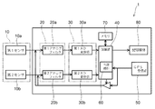
図1は、本実施形態に係る地震観測装置を例示するブロック図である。
図1に示すように、本実施形態に係る地震観測装置1は、地震の揺れを検知する検知部10と、検知部10から出力された信号を処理するアナログフィルタ20と、アナログフィルタ20から出力された処理後信号に基づき演算を行い、地震データを出力する演算部40と、を備える。また、本実施形態に係る地震観測装置1では、これらの構成に加え、アナログデジタル変換部(以下、「AD変換部」と言う。)30、GPS(全地球測位システム)受信部50、内部時計60、メモリ70および記録媒体80を備えている。
[Overall configuration of earthquake observation equipment]
FIG. 1 is a block diagram illustrating a seismic observation apparatus according to this embodiment.
As shown in FIG. 1, the
検知部10には、例えば複数のセンサが設けられる。図1には、第1センサ10aおよび第2センサ10bの2つのセンサが示される。第1センサ10aは、第1軸の方向に沿った加速度を検知する第1加速度センサである。第2センサ10bは、第1軸とは異なる第2軸に沿った加速度を検知する第2加速度センサである。なお、通常、地震観測装置1ではX軸、Y軸、Z軸の3軸に沿った加速度を検知するため、3つのセンサが設けられる。説明の便宜上、本実施形態では2軸に沿った加速度を検知する2つのセンサが設けられている場合を例とする。
For example, the
第1センサ10aおよび第2センサ10bのそれぞれに対応して、アナログフィルタ20およびAD変換部30についてもそれぞれ2つ設けられる。すなわち。第1センサ10aの後段には第1アナログフィルタ20aが設けられ、第1アナログフィルタ20aの後段には第1AD変換部30aが設けられる。また、第2センサ10bの後段には第2アナログフィルタ20bが設けられ、第2アナログフィルタ20bの後段には第2AD変換部30bが設けられる。本実施形態では、複数のセンサのそれぞれについての信号処理ラインを「系統」と言うことにする。
Two
アナログフィルタ20は、抵抗やコンデンサなどの素子によって構成される。アナログフィルタ20は、検知部10(第1センサ10aおよび第2センサ10bの総称)で検知した信号(地震による加速度を検知した信号)のうち特定の周波数を超える信号成分を除去する。すなわち、アナログフィルタ20(第1アナログフィルタ20aおよび第2アナログフィルタ20bを総称)は、ローパスフィルタである。
The
AD変換部30によってアナログ信号をデジタル信号に変換する場合、AD変換部30によるサンプリング周波数の1/2よりも高い周波数の信号をアナログフィルタ20によってカットする必要がある。したがって、ローパスフィルタであるアナログフィルタ20のカットオフ周波数はAD変換部30によるサンプリング周波数の1/2となる。
When the analog signal is converted into a digital signal by the
AD変換部30(第1AD変換部30aおよび第2AD変換部30bの総称)は、アナログフィルタ20を通過したアナログ信号を、所定のサンプリング周波数によってデジタル信号に変換する。微小な加速度の変化を検知する必要のある地震観測装置では、AD変換部30は高分解能であることが要求される。AD変換部30として、例えばデルタシグマ(ΔΣ)型AD変換器を用いるとよい。
The AD conversion unit 30 (a general term for the first
演算部40は、AD変換部30から出力されるデジタル信号を処理して、時間に対する地震の振動波形を出力する。また、演算部40は、必要に応じて振動波形から震度の値を算出して出力する。演算部40から出力された情報は、記録媒体80に記録される。
The
地震観測装置1では、地震が発生した正確な時刻と、時間経過に対応した精度の高い振動波形の取得とが重要である。このため、演算部40は正確な時間(時刻)の情報を保持している。正確な時間は、例えばGPS受信部50で受信して出力される基準時刻信号によって得ることができる。基準時刻信号には、GPS受信部50で受信した正確な時刻情報および1秒幅のパルス信号が含まれる。演算部40は、GPS受信部50で受信した時刻情報および1秒幅のパルス信号を受けて、内部時計60を正確な時刻に設定する。なお、GPS受信部50が設けられていない場合、他の手段(例えば、インターネット経由での時刻情報取得)によって内部時計60に正確な時刻を設定するようにしてもよい。
In the
メモリ70は、後述する信号遅延量を記憶する記憶部である。演算部40は、信号遅延量を取得して、メモリ70に予め記憶しておく処理を行う。また、地震観測装置1にはゲート90が設けられていてもよい。ゲート90は、演算部40によって信号遅延量を取得する際、基準時刻信号をアナログフィルタ20の前段へ送るか否かを制御する。
The
〔信号遅延〕
次に、信号遅延について説明する。
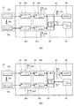
図2(a)および(b)は、地震観測装置の信号遅延について例示するブロック図である。
図2(a)にはAD変換部30での信号遅延が例示され、図2(b)にはアナログフィルタ20での信号遅延が示される。
検知部10で検知した地震の揺れに基づく信号WSは、アナログフィルタ20やAD変換部30を通過する際に遅延する。演算部40では、地震の揺れを検知した時刻と地震データとが合致するように信号遅延を補正する処理を行い、地震データとして記録媒体80へ出力する。
[Signal delay]
Next, signal delay will be described.
2A and 2B are block diagrams illustrating signal delay of the seismic observation apparatus.
FIG. 2A illustrates a signal delay in the
The signal WS based on the earthquake shake detected by the
ここで、AD変換部30だけの信号遅延に着目した場合、図2(a)に示すように、AD変換部30のようなデジタルフィルタについては直線位相特性を持っている。すなわち、第1AD変換部30aおよび第2AD変換部30bともにばらつきなく同じ信号遅延量DSとなる。演算部40は、入力された信号に対して第1AD変換部30aおよび第2AD変換部30bの信号遅延量DSの示す遅延分CSを補正する処理を行う。これにより、第1AD変換部30aおよび第2AD変換部30bでの信号遅延は正確に補正される。
Here, when attention is paid to the signal delay of only the
また、アナログフィルタ20だけの信号遅延に着目した場合、図2(b)に示すように、アナログフィルタ20についてはフィルタを構成する素子によって信号遅延量DS1、DS2にばらつきが生じる。すなわち、第1アナログフィルタ20aおよび第2アナログフィルタ20bのそれぞれについて別個に信号遅延量DS1、DS2があり、同じ回路構成であっても信号遅延量DS1、DS2に差が生じる。さらに、温度や湿度等の環境変化によっても信号遅延量DS1、DS2に変化が生じる。したがって、演算部40において、アナログフィルタ20での信号遅延量を正確に補正することは困難である。
When attention is paid to the signal delay of only the
地震観測装置では、地震発生前から発生時点、さらには地震の揺れが終わるまでの時間の経過と地震による震動波形との対応付けが非常に重要となる。このため、信号遅延の補正を正確に行う必要がある。したがって、デジタルフィルタのみならずアナログフィルタ20による信号遅延分も正確に補正することが要求される。
In an earthquake observation apparatus, it is very important to correlate the passage of time from the occurrence of an earthquake to the time of occurrence, and further to the end of the earthquake, and the vibration waveform of the earthquake. For this reason, it is necessary to correct the signal delay accurately. Therefore, it is required to accurately correct not only the digital filter but also the signal delay caused by the
〔信号遅延の補正〕
次に、本実施形態に係る地震観測装置1での信号遅延の補正について説明する。
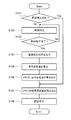
図3は、信号遅延の補正処理の流れを例示するフローチャートである。
図4は、地震観測装置での信号遅延の補正を例示するブロック図である。
本実施形態に係る地震観測装置1では、演算部40によってアナログフィルタ20での信号遅延量DS1、DS2を予め取得しておき、検知した地震データに対して信号遅延量DS1、DS2の示す遅延分CS1、CS2を補正する処理を行う。これにより、アナログフィルタ20での信号遅延量DS1、DS2を補正した地震データを得ることができる。
[Signal delay correction]
Next, correction of signal delay in the
FIG. 3 is a flowchart illustrating the flow of signal delay correction processing.
FIG. 4 is a block diagram illustrating correction of signal delay in the seismic observation apparatus.
In the
図3に示す各ステップの処理は、演算部40によって行われる。各ステップの処理は、例えば演算部40で実行されるプログラム処理によって実施される。
先ず、図3のステップS101に示すように、遅延補正済みか否かの判断を行う。遅延補正済みであれば、ステップS107へ進む。遅延補正済みでない場合には、ステップS102へ進む。ステップS102では、GPS受信部50によって受信した基準時刻信号に基づき、内部時計60の時刻の補正を行う。
The processing of each step shown in FIG. The process of each step is implemented by a program process executed by the
First, as shown in step S101 of FIG. 3, it is determined whether or not delay correction has been completed. If the delay has been corrected, the process proceeds to step S107. If the delay has not been corrected, the process proceeds to step S102. In step S102, the time of the
次に、ステップS103に示すように、時刻補正が完了したか否かの判断を行う。時刻補正が完了していない場合にはステップS102に戻る。時刻補正が完了した場合にはステップS104へ進む。 Next, as shown in step S103, it is determined whether or not the time correction has been completed. If the time correction has not been completed, the process returns to step S102. When the time correction is completed, the process proceeds to step S104.
ステップS104では、GPS受信部50で受信した基準時刻信号TSをアナログフィルタ20の前段に出力する処理を行う。すなわち、演算部40はゲート90を制御して、GPS受信部50で受信した基準時刻信号TSの1秒幅のパルス信号をアナログフィルタ20の前段に出力する。演算部40は、アナログフィルタ20の前段に基準時刻信号TSを出力した時刻(基準時刻)を記録しておく。
In step S104, a process of outputting the reference time signal TS received by the
次に、ステップS105に示すように、アナログフィルタ20およびAD変換部30を通過した1秒幅のパルス信号が演算部40に入力された時刻と、予め記録した基準時刻との差から信号遅延量を算出する。ここで、信号遅延量は、複数のセンサの信号処理ラインにおける各系統ごとに算出される。すなわち、図4に示すように、第1センサ10aおよび第2センサ10bについて2つの信号処理ラインの系統が設けられている場合には、2つの信号遅延量DS1、DS2が算出される。
Next, as shown in step S105, the signal delay amount is calculated based on the difference between the time when the pulse signal having a width of 1 second that has passed through the
次に、ステップS106に示すように、演算部40は取得した信号遅延量DS1、DS2をメモリ70に書き込む処理を行う。信号遅延量DS1、DS2は、各系統ごとにメモリ70に書き込まれる。
Next, as shown in step S <b> 106, the
次に、ステップS107に示すように、演算部40はメモリ70に書き込まれた信号遅延量DS1、DS2を読み込み、ステップS108に示すように、遅延補正を行う。すなわち、ステップS107〜ステップS108の処理は、実際に検知部10から出力される信号についての遅延補正である。
Next, as shown in step S107, the
この遅延補正では、予め取得したアナログフィルタ20を含む回路の信号遅延量DS1、DS2の示す遅延分CS1、CS2を補正する処理を行う。信号遅延量DS1、DS2は各系統ごとに取得されているため、各系統ごとの信号について対応する信号遅延量DS1、DS2の示す遅延分CS1、CS2を補正する処理を行う。これにより、アナログフィルタ20を含む信号処理回路であっても、そのアナログフィルタ20についての個別の信号遅延量DS1、DS2に基づいた遅延補正CS1、CS2を行うことができ、高精度な地震データを得ることができる。
In this delay correction, a process of correcting the delays CS1 and CS2 indicated by the signal delay amounts DS1 and DS2 of the circuit including the
上記の信号遅延の補正処理においてはGPS受信部50で受信した基準時刻信号TSを用いているが、GPS受信部50が設けられていない場合やGPS受信部50で基準時刻信号TSを受信できない状況の場合には、内部時計60から基準時刻信号TSを出力するようにしてもよい。
In the above signal delay correction processing, the reference time signal TS received by the
なお、図3に示す信号遅延の補正処理のフローチャートにおいて、ステップS101〜ステップS106までの処理(信号遅延量の算出および書き込み)は、地震観測装置1の電源を立ち上げたときや、地震観測装置1の定期点検を行ったとき、また任意のタイミングで適宜行うようにすればよい。
In the flowchart of the signal delay correction process shown in FIG. 3, the processes from step S101 to step S106 (calculation and writing of the signal delay amount) are performed when the
〔他の実施形態〕
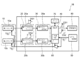
図5は、他の実施形態に係る地震観測装置を例示するブロック図である。
図5に示すように、他の実施形態に係る地震観測装置1Bでは、信号遅延量を取得する際に用いる基準時刻信号(例えば、1秒幅のパルス信号)TSが検知部10に入力される。基準時刻信号TSは、ゲート90を介して検知部10の第1センサ10aおよび第2センサ10bにそれぞれ入力される。
[Other Embodiments]
FIG. 5 is a block diagram illustrating an earthquake observation apparatus according to another embodiment.
As shown in FIG. 5, in the
地震観測装置1Bでは、アナログフィルタ20に加え、第1センサ10aおよび第2センサ10b内にもアナログフィルタ等のアナログ回路が含まれている。また、検知部10とアナログフィルタ20との間にプリアンプなどのアナログ回路(図示せず)が含まれる場合もある。このような構成において、各系統におけるアナログ回路を含めた信号遅延量DS1、DS2を取得するため、地震観測装置1Bでは、基準時刻信号TSを検知部10の第1センサ10aおよび第2センサ10bにそれぞれ入力している。
In the
このような構成によって、各系統における信号遅延量DS1、DS2を取得する場合には、基準時刻信号TSを第1センサ10aおよび第2センサ10bにそれぞれ入力する。演算部40は、基準時刻信号TSが第1センサ10aおよび第2センサ10bに入力された時刻と、各系統を通過してこの基準時刻信号TSを受けた時刻との差から信号遅延量DS1、DS2を取得し、メモリ70に記憶しておく。そして、実際の地震の揺れを検知した際の信号処理において、メモリ70に記憶した信号遅延量DS1、DS2の示す遅延分CS1、CS2を補正する。これにより、各系統に含まれるアナログ回路での信号遅延を正確に補正することができる。
With this configuration, when the signal delay amounts DS1 and DS2 in each system are acquired, the reference time signal TS is input to the
以上説明したように、実施形態によれば、アナログフィルタ20を含む信号処理回路での信号遅延を高精度に補正することができる地震観測装置1、1Bを提供することができる。
As described above, according to the embodiment, it is possible to provide the
なお、上記に本実施形態を説明したが、前述の各実施形態に対して、当業者が適宜、構成要素の追加、削除、設計変更を行ったものや、各実施形態の特徴を適宜組み合わせたものも、本発明の要旨を備えている限り、本発明の範囲に含有される。 In addition, although this embodiment was described above, those skilled in the art appropriately added, deleted, and changed the design of each of the above-described embodiments, and appropriately combined the features of each embodiment. Those are also included in the scope of the present invention as long as they have the gist of the present invention.
1,1B…地震観測装置
10…検知部
10a…第1センサ
10b…第2センサ
20…アナログフィルタ
20a…第1アナログフィルタ
20b…第2アナログフィルタ
30…AD変換部
30a…第1AD変換部
30b…第2AD変換部
40…演算部
50…GPS受信部
60…内部時計
70…メモリ
80…記録媒体
90…ゲート
DESCRIPTION OF
Claims (6)
前記検知部から出力された信号を処理するアナログフィルタと、
前記アナログフィルタから出力された処理後信号に基づき演算を行い、地震データを出力する演算部と、
を備え、
前記演算部は、基準となる時刻の情報を含む基準時刻信号を前記アナログフィルタに入力して前記アナログフィルタでの信号遅延量を取得し、前記地震データに対して前記信号遅延量の示す遅延分を補正する処理を行うことを特徴とする地震観測装置。 A detection unit for detecting earthquake shaking;
An analog filter for processing the signal output from the detection unit;
An operation is performed based on the processed signal output from the analog filter, and outputs earthquake data;
With
The arithmetic unit inputs a reference time signal including reference time information to the analog filter to obtain a signal delay amount in the analog filter, and a delay amount indicated by the signal delay amount with respect to the earthquake data. A seismic observation apparatus characterized by performing a process for correcting the vibration.
前記演算部は、前記記憶部から前記信号遅延量を読み出して前記遅延分を補正する処理を行う、請求項1〜3のいずれか1つに記載の地震観測装置。 A storage unit that stores in advance the signal delay amount acquired by the calculation unit;
The earthquake observation apparatus according to any one of claims 1 to 3, wherein the arithmetic unit performs a process of reading the signal delay amount from the storage unit and correcting the delay amount.
前記アナログフィルタは、前記第1加速度センサから出力された第1信号を処理する第1アナログフィルタと、前記第2加速度センサから出力された第2信号を処理する第2アナログフィルタと、を有し、
前記演算部は、前記基準時刻信号を前記第1アナログフィルタおよび前記第2アナログフィルタのそれぞれに入力して前記信号遅延量における前記第1アナログフィルタでの第1信号遅延量および前記第2アナログフィルタでの第2信号遅延量を取得し、前記地震データにおける前記第1軸に沿った第1地震データに対して前記第1信号遅延量の示す第1遅延分を補正する処理および前記第2軸に沿った第2地震データに対して前記第2信号遅延量の示す第2遅延分を補正する処理を行う、請求項1〜5のいずれか1つに記載の地震観測装置。 The detection unit includes a first acceleration sensor that detects acceleration along a first axis, and a second acceleration sensor that detects acceleration along a second axis different from the first axis,
The analog filter includes a first analog filter that processes a first signal output from the first acceleration sensor, and a second analog filter that processes a second signal output from the second acceleration sensor. ,
The arithmetic unit inputs the reference time signal to each of the first analog filter and the second analog filter, and the first signal delay amount in the first analog filter and the second analog filter in the signal delay amount Processing for obtaining a second signal delay amount at the first axis and correcting the first delay amount indicated by the first signal delay amount for the first earthquake data along the first axis in the earthquake data and the second axis The earthquake observation apparatus according to claim 1, wherein a process of correcting a second delay indicated by the second signal delay amount is performed on the second earthquake data along the line.
Priority Applications (1)
| Application Number | Priority Date | Filing Date | Title |
|---|---|---|---|
| JP2016138827A JP2018009878A (en) | 2016-07-13 | 2016-07-13 | Earthquake observation device |
Applications Claiming Priority (1)
| Application Number | Priority Date | Filing Date | Title |
|---|---|---|---|
| JP2016138827A JP2018009878A (en) | 2016-07-13 | 2016-07-13 | Earthquake observation device |
Publications (1)
| Publication Number | Publication Date |
|---|---|
| JP2018009878A true JP2018009878A (en) | 2018-01-18 |
Family
ID=60995394
Family Applications (1)
| Application Number | Title | Priority Date | Filing Date |
|---|---|---|---|
| JP2016138827A Pending JP2018009878A (en) | 2016-07-13 | 2016-07-13 | Earthquake observation device |
Country Status (1)
| Country | Link |
|---|---|
| JP (1) | JP2018009878A (en) |
-
2016
- 2016-07-13 JP JP2016138827A patent/JP2018009878A/en active Pending
Similar Documents
| Publication | Publication Date | Title |
|---|---|---|
| JP3772121B2 (en) | Encoder signal processing device | |
| US9952065B2 (en) | Position sensor device to determine a position of a moving device | |
| CN110108312B (en) | Method, computer program, device and encoder for signal error correction | |
| US9967677B2 (en) | System and method for sensor-supported microphone | |
| US9037386B2 (en) | Sensor signal processing device | |
| JP4597204B2 (en) | Sensor module and method for correcting detection output signal of sensor module | |
| CN113014206B (en) | Scale factor temperature drift compensation device and method for current/frequency conversion circuit | |
| JP2016161276A (en) | Current sensor circuit | |
| CN104515611A (en) | Temperature sensing circuit and temperature sensor | |
| JP2018009878A (en) | Earthquake observation device | |
| JP2002107256A (en) | Pressure sensor circuit | |
| JP2023548610A (en) | Position sensing system, method for acquiring position sensing signals, and electronic equipment | |
| JP5162739B2 (en) | Encoder signal processing method, encoder device, and servo motor | |
| JP2017118314A (en) | Electronic control unit | |
| JP7463081B2 (en) | Seismic wave recording device and seismic wave recording method | |
| JP2019203854A (en) | Position detector | |
| JP6649419B2 (en) | Encoder signal processing device and encoder | |
| EP3569986B1 (en) | Position sensing device | |
| US9709610B2 (en) | System comprising a probe and a measuring device | |
| JP6102785B2 (en) | Physical quantity sensor | |
| CN120090632A (en) | DAC signal calibration device, method, electronic device and storage medium | |
| JP5687223B2 (en) | Signal processing device, rotation angle detection device, and adjustment value setting device | |
| KR101068837B1 (en) | Accelerometer measurement signal error compensation device and method | |
| CN118511056A (en) | Angle sensor device and angle determination method | |
| JP6085525B2 (en) | Electronic circuit and driving method thereof |