JP2018009836A - Program, head-mounted display device, calibration method - Google Patents
Program, head-mounted display device, calibration method Download PDFInfo
- Publication number
- JP2018009836A JP2018009836A JP2016137529A JP2016137529A JP2018009836A JP 2018009836 A JP2018009836 A JP 2018009836A JP 2016137529 A JP2016137529 A JP 2016137529A JP 2016137529 A JP2016137529 A JP 2016137529A JP 2018009836 A JP2018009836 A JP 2018009836A
- Authority
- JP
- Japan
- Prior art keywords
- marker
- image
- unit
- image display
- real marker
- Prior art date
- Legal status (The legal status is an assumption and is not a legal conclusion. Google has not performed a legal analysis and makes no representation as to the accuracy of the status listed.)
- Pending
Links
Images

Classifications
-
- G—PHYSICS
- G06—COMPUTING OR CALCULATING; COUNTING
- G06T—IMAGE DATA PROCESSING OR GENERATION, IN GENERAL
- G06T7/00—Image analysis
- G06T7/80—Analysis of captured images to determine intrinsic or extrinsic camera parameters, i.e. camera calibration
-
- G—PHYSICS
- G02—OPTICS
- G02B—OPTICAL ELEMENTS, SYSTEMS OR APPARATUS
- G02B27/00—Optical systems or apparatus not provided for by any of the groups G02B1/00 - G02B26/00, G02B30/00
- G02B27/01—Head-up displays
- G02B27/017—Head mounted
- G02B27/0172—Head mounted characterised by optical features
-
- G—PHYSICS
- G02—OPTICS
- G02B—OPTICAL ELEMENTS, SYSTEMS OR APPARATUS
- G02B27/00—Optical systems or apparatus not provided for by any of the groups G02B1/00 - G02B26/00, G02B30/00
- G02B27/01—Head-up displays
- G02B27/017—Head mounted
- G02B27/0176—Head mounted characterised by mechanical features
-
- G—PHYSICS
- G06—COMPUTING OR CALCULATING; COUNTING
- G06T—IMAGE DATA PROCESSING OR GENERATION, IN GENERAL
- G06T7/00—Image analysis
- G06T7/30—Determination of transform parameters for the alignment of images, i.e. image registration
- G06T7/33—Determination of transform parameters for the alignment of images, i.e. image registration using feature-based methods
- G06T7/337—Determination of transform parameters for the alignment of images, i.e. image registration using feature-based methods involving reference images or patches
-
- G—PHYSICS
- G02—OPTICS
- G02B—OPTICAL ELEMENTS, SYSTEMS OR APPARATUS
- G02B27/00—Optical systems or apparatus not provided for by any of the groups G02B1/00 - G02B26/00, G02B30/00
- G02B27/01—Head-up displays
- G02B27/0101—Head-up displays characterised by optical features
- G02B2027/0138—Head-up displays characterised by optical features comprising image capture systems, e.g. camera
-
- G—PHYSICS
- G02—OPTICS
- G02B—OPTICAL ELEMENTS, SYSTEMS OR APPARATUS
- G02B27/00—Optical systems or apparatus not provided for by any of the groups G02B1/00 - G02B26/00, G02B30/00
- G02B27/01—Head-up displays
- G02B27/017—Head mounted
- G02B2027/0178—Eyeglass type
-
- G—PHYSICS
- G06—COMPUTING OR CALCULATING; COUNTING
- G06T—IMAGE DATA PROCESSING OR GENERATION, IN GENERAL
- G06T2207/00—Indexing scheme for image analysis or image enhancement
- G06T2207/20—Special algorithmic details
- G06T2207/20212—Image combination
- G06T2207/20221—Image fusion; Image merging
-
- G—PHYSICS
- G06—COMPUTING OR CALCULATING; COUNTING
- G06T—IMAGE DATA PROCESSING OR GENERATION, IN GENERAL
- G06T2207/00—Indexing scheme for image analysis or image enhancement
- G06T2207/30—Subject of image; Context of image processing
- G06T2207/30204—Marker
Landscapes
- Physics & Mathematics (AREA)
- General Physics & Mathematics (AREA)
- Engineering & Computer Science (AREA)
- Optics & Photonics (AREA)
- Computer Vision & Pattern Recognition (AREA)
- Theoretical Computer Science (AREA)
- Controls And Circuits For Display Device (AREA)
- Length Measuring Devices By Optical Means (AREA)
- Studio Devices (AREA)
- Image Analysis (AREA)
- Processing Or Creating Images (AREA)
Abstract
Description
本発明は、空間関係のキャリブレーションに関する。 The present invention relates to spatial relationship calibration.
ユーザーの頭部に装着される頭部装着型表示装置(以下、HMDともいう)が知られている。例えば、特許文献1には、支持手段を介して支持された撮像手段が、HMDの本体に対して上下にスライドするビデオシースルー型HMDが開示されている。 2. Description of the Related Art A head-mounted display device (hereinafter also referred to as HMD) that is mounted on a user's head is known. For example, Patent Document 1 discloses a video see-through HMD in which an imaging unit supported via a supporting unit slides up and down with respect to the main body of the HMD.
以下では、シースルー型の表示装置の一例として、AR(拡張現実)機能を提供できるように、トラッキングカメラを備えるHMDを例として説明する。HMDは、トラッキングカメラを介して、HMD(またはトラッキングカメラ)に対する実オブジェクトの位置を検出し、追跡する(この方式による実オブジェクトの追跡を「光学トラッキング」と表記する)。HMDは、当該実オブジェクトの位置に追従するように、CG等の仮想オブジェクトを表示する。このときユーザーは、実オブジェクトの位置に、仮想オブジェクトの位置が対応付けられるように、仮想オブジェクトを視認する。 Hereinafter, as an example of a see-through display device, an HMD including a tracking camera so as to provide an AR (augmented reality) function will be described as an example. The HMD detects and tracks the position of the real object with respect to the HMD (or tracking camera) via the tracking camera (tracking the real object by this method is referred to as “optical tracking”). The HMD displays a virtual object such as CG so as to follow the position of the real object. At this time, the user visually recognizes the virtual object so that the position of the virtual object is associated with the position of the real object.
トラッキングカメラの視野における実オブジェクトの位置と姿勢は、実オブジェクトの動きだけでなく、ユーザーの頭部の動き(特に回転)によっても変化する。そして、頭部の回転の角速度が速く、および/または角度が大きい場合には、光学トラッキングだけでは、仮想オブジェクトの表示に、実オブジェクトの位置、さらには姿勢の変化が反映されるまでの時間差(レイテンシー)が目立つようになる場合がある。 The position and orientation of the real object in the visual field of the tracking camera change not only with the movement of the real object but also with the movement (particularly rotation) of the user's head. When the angular velocity of the rotation of the head is high and / or the angle is large, the time difference until the change of the position of the real object and further the posture is reflected on the display of the virtual object only by optical tracking ( (Latency) may become noticeable.
技術的に、トラッキングカメラの時間分解能(画像のフレームレート)より、慣性センサーの時間分解能を高くしやすい。そこで、上記レイテンシー対策として、HMDが、トラッキングカメラだけでなく、慣性センサーを搭載し、トラッキングカメラと慣性センサーとによって、HMDに対する実オブジェクトの位置・姿勢(実オブジェクトとHMDとの間の空間的位置関係)を推定することが効果的であると考えられる(この方式による実オブジェクトの追跡を「慣性・光学融合トラッキング」と表記する)。 Technically, the time resolution of the inertial sensor is likely to be higher than the time resolution (image frame rate) of the tracking camera. Therefore, as a countermeasure against the above-described latency, the HMD has not only a tracking camera but also an inertial sensor, and the tracking camera and the inertial sensor allow the position / posture of the real object relative to the HMD (the spatial position between the real object and the HMD). It is considered effective to estimate the relationship) (tracking a real object by this method is expressed as “inertia / optical fusion tracking”).
上記場合のように、トラッキングカメラと慣性センサーとが協働して「トラッカー(追跡装置)」として機能する場合には、トラッキングカメラの座標系と慣性センサーの座標系とが、対応付けられている(較正されている)ことが望まれる。また、上記「トラッカー」として利用される場合以外でも、例えば、ユーザーの眼(網膜)を基準にしてトラッキングカメラと画像表示部とが較正される場合に、トラッキングカメラの座標系と慣性センサーの座標系とが較正されていることは、有用である。そして、較正方法は簡易で、かつ較正結果が高精度であることが望ましい。 When the tracking camera and the inertial sensor cooperate to function as a “tracker (tracking device)” as in the above case, the tracking camera coordinate system and the inertial sensor coordinate system are associated with each other. It is desired (calibrated). In addition, when the tracking camera and the image display unit are calibrated on the basis of the user's eye (retina), for example, the coordinate system of the tracking camera and the coordinates of the inertial sensor are also used other than the case where the tracker is used. It is useful that the system is calibrated. It is desirable that the calibration method is simple and the calibration result is highly accurate.
さらに、光学シースルー型の頭部装着型表示装置を含む画像表示装置が、カメラによって撮像された特定の対象物の位置に画像を精度良く重畳させて表示させる技術を備えれば、AR機能に関して、向上した利便性を提供することができる。ただし、カメラで撮像した特定の対象物に表示画像を正しく重畳させる際には、カメラと画像表示部との間の空間的関係を較正することが望まれる。 Furthermore, if the image display device including the optical see-through type head-mounted display device has a technique for accurately superimposing and displaying an image on the position of a specific object imaged by the camera, Improved convenience can be provided. However, it is desirable to calibrate the spatial relationship between the camera and the image display unit when the display image is correctly superimposed on a specific object captured by the camera.
上記の通り、2つの較正を実施することが好ましいものの、2つの較正をそれぞれ成功させるのは難しい。本願発明は、上記を踏まえ、撮像部(トラッキングカメラ)および慣性センサーの間の空間関係(第1の空間関係)、並びに撮像部および画像表示部の間の空間関係(第2の空間関係)の較正の成功率を高めることを解決課題とする。 As described above, although it is preferable to perform two calibrations, it is difficult to succeed in each of the two calibrations. Based on the above, the present invention relates to the spatial relationship between the imaging unit (tracking camera) and the inertial sensor (first spatial relationship) and the spatial relationship between the imaging unit and the image display unit (second spatial relationship). The challenge is to increase the success rate of calibration.
本発明は、上記課題を解決するためのものであり、以下の形態として実現できる。 SUMMARY An advantage of some aspects of the invention is to solve the above-described problems, and the invention can be implemented as the following forms.
本発明の一形態は、撮像部と、慣性センサーと、光学透過型の画像表示部と、処理部と、を備えた頭部装着型表示装置の前記処理部に;前記第1の実物マーカーに対する前記撮像部の相対位置が第1の位置と、第2の位置との場合において前記撮像部に前記第1の実物マーカーを撮像させて得られる撮像画像を取得する機能と;前記第1の位置から前記第2の位置への前記慣性センサーの動きを、前記慣性センサーの出力に基づき導出する機能と;第2の実物マーカーに対応したマーカー画像を前記画像表示部に表示する機能と;前記マーカー画像と前記第2の実物マーカーとが一致するようにユーザーに視認される状態において、前記撮像部に前記第2の実物マーカーを撮像させて得られる撮像画像を取得する機能と;前記撮像部および前記慣性センサーの間の第1の空間関係、並びに前記撮像部および前記画像表示部の間の第2の空間関係を、前記第1の実物マーカーの撮像画像と、前記慣性センサーの動きと、前記第2の実物マーカーの撮像画像と、に基づき導出する機能と;を実現させるためのプログラムである。この形態によれば、第1及び第2の空間関係の較正の成功率が上がる。なお、第1の実物マーカー及び第2の実物マーカーは、同じ物であってもよいし、違う物であってもよい。 According to one aspect of the present invention, the processing unit of the head-mounted display device including an imaging unit, an inertial sensor, an optically transmissive image display unit, and a processing unit; A function of acquiring a captured image obtained by causing the imaging unit to image the first real marker when the relative position of the imaging unit is the first position and the second position; A function of deriving a movement of the inertial sensor from the first position to the second position based on an output of the inertial sensor; a function of displaying a marker image corresponding to a second real marker on the image display unit; A function of acquiring a captured image obtained by causing the imaging unit to image the second real marker in a state where the image is visually recognized by the user so that the second real marker matches, the imaging unit; Previous The first spatial relationship between the inertial sensors and the second spatial relationship between the imaging unit and the image display unit are the captured image of the first real marker, the motion of the inertial sensor, and the first And a function derived on the basis of the captured image of the two real markers. According to this aspect, the success rate of the calibration of the first and second spatial relationships is increased. Note that the first real marker and the second real marker may be the same or different.
上記形態において、前記撮像部は、前記慣性センサーに対する相対位置が可動であってもよい。 In the above embodiment, the imaging unit may be movable in a relative position with respect to the inertial sensor.
上記形態において、前記撮像部は、前記画像表示部に対する相対位置が可動であってもよい。 In the above aspect, the imaging unit may be movable in a relative position with respect to the image display unit.
本発明は、上記以外の種々の形態で実現できる。例えば、上記のプログラムを記憶した一時的でない記憶媒体の形態で実現できる。或いは、上記のプログラムを実行することで動作する装置や、上記のプログラムによって実現される方法等の形態で実現できる。 The present invention can be realized in various forms other than the above. For example, it can be realized in the form of a non-temporary storage medium storing the above program. Alternatively, it can be realized in the form of a device that operates by executing the above program, a method realized by the above program, and the like.
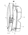
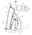
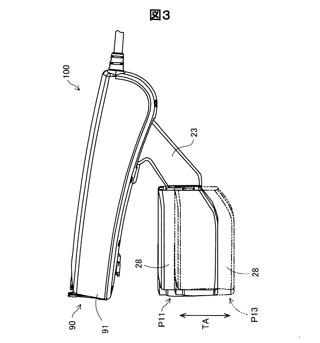
図1〜図3は、頭部装着型表示装置100(HMD100)の外観構成を示す。HMD100は、画像表示部20が表示する表示画像をユーザーに視認させ、画像表示部20(図1)を透過する外景からの光によって当該外景もユーザーに視認させることができる。詳細な構成については後述するが、本実施形態のHMD100は、画像表示部20を装着したユーザーの右眼と左眼とのそれぞれに対応する画像表示部を有しており、ユーザーの右眼と左眼とに別々の画像を視認させることができる。
1 to 3 show an external configuration of the head-mounted display device 100 (HMD 100). The HMD 100 allows the user to visually recognize the display image displayed by the
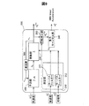
図2に示すように、HMD100は、ユーザーの頭部装着型表示装置に装着される装着帯90と、装着帯90に接続されている画像表示部20と、画像表示部20を制御する制御部10と、制御部10と装着帯90とを接続する接続部40と、を備えている。図1に示すように、装着帯90は、樹脂製の装着基部91と、装着基部91に連結される布製のベルト部92と、カメラ60と、IMU71と、を備える。装着基部91は、人の前頭部の形に合った湾曲した形状を有する。ベルト部92は、ユーザーの頭部の周りに装着されるためのベルトである。なお、接続部40は、装着帯90と制御部10側とを有線で接続しているが、図2では、接続している部分については、図示を省略している。
As shown in FIG. 2, the HMD 100 includes a wearing
カメラ60は、外景を撮像可能で、装着基部91の中心部分に配置されている。換言すると、カメラ60は、装着帯90がユーザーの頭部に装着された状態で、ユーザーの額の中央に対応する位置に配置されている。そのため、カメラ60は、ユーザーが装着帯90を頭部に装着した状態において、ユーザーの視線方向の外部の景色である外景を撮像し、撮像された画像である撮像画像を取得する。図2に示すように、カメラ60は、装着基部91に対して、円弧RCに沿って所定の範囲で可動する。換言すると、カメラ60は、撮像範囲を所定の範囲で変更できる。
The
IMU71(Inertial Measurement Unit)は、加速度を検出する慣性センサーである。また、本実施形態のIMU71は、加速度に加えて、角速度と、地磁気とを検出できる。IMU71は、装着基部91におけるカメラ60の近くに内蔵されている。そのため、IMU71は、装着帯90の加速度と角速度と地磁気とを検出する。
An IMU 71 (Inertial Measurement Unit) is an inertial sensor that detects acceleration. Further, the
図2に示すように、画像表示部20は、連結部93を介して装着基部91に接続され、眼鏡形状を有している。連結部93は、装着基部91および画像表示部20の両側に対称的に配置され、連結部93を中心として、装着基部91に対する画像表示部20の位置を円弧RAに沿って回転可能に支持する。図2において二点鎖線で示す位置P11は、画像表示部20が円弧RAに沿った最も下端である。また、図2において実線で示す位置P12は、画像表示部20が円弧RAに沿った最も上端である。
As shown in FIG. 2, the
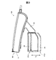
図3に示すように、画像を表示可能な表示パネルを有する光学像表示部26,28は、保持部21,23に対して、直線TAに沿って所定の範囲で平行移動して位置を変更する。図3において二点鎖線で示す位置P13は、光学像表示部26,28が直線TAに沿った最も下端である。図3において実線で示す位置P11は、光学像表示部26,28が直線TAに沿った最も上端である。なお、図2における位置P11と、図3における位置P11とは、同じ位置を示している。
As shown in FIG. 3, the optical
図1に示すように、画像表示部20は、右保持部21と、右表示駆動部22と、左保持部23と、左表示駆動部24と、右光学像表示部26と、左光学像表示部28と、を含んでいる。右光学像表示部は、ユーザーが画像表示部20を装着した際にユーザーの右の眼前に位置するように配置されている。左光学像表示部28は、ユーザーが画像表示部20を装着した際にユーザーの左の眼前に位置するように配置されている。右光学像表示部26の一端と左光学像表示部28の一端とは、ユーザーが画像表示部20を装着した際のユーザーの眉間に対応する位置で、互いに接続されている。
As shown in FIG. 1, the
右保持部21は、右光学像表示部26の他端から装着基部91と接続されている連結部93に延伸して設けられた部材である。同様に、左保持部23は、左光学像表示部28の他端から連結部93に延伸して設けられた部材である。右表示駆動部22と左表示駆動部24とは、ユーザーが画像表示部20を装着した際のユーザーの頭部に対向する側に配置されている。
The
表示駆動部22,24は、図4で後述する液晶ディスプレイ241,242(Liquid Crystal Display、以下「LCD241,242」とも呼ぶ)や投写光学系251,252等を含む。表示駆動部22,24の構成の詳細な説明は後述する。光学像表示部26,28は、後述する導光板261,262(図4参照)と調光板とを含んでいる。導光板261,262は、光透過性の樹脂材料等によって形成され、表示駆動部22,24から出力された画像光をユーザーの眼に導く。調光板は、薄板状の光学素子であり、ユーザーの眼の側とは反対の側である画像表示部20の表側を覆うように配置されている。調光板の光透過率を調整することによって、ユーザーの眼に入る外光量を調整して虚像の視認のしやすさを調整できる。
The
制御部10は、HMD100を制御するための装置である。制御部10は、静電式のトラックパッドや押下可能な複数のボタンなどを含む操作部135を有する。
The
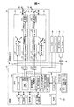
図4は、HMD100の構成を機能的に示すブロック図である。図4に示すように、制御部10は、ROM121と、RAM122と、電源130と、操作部135と、マーカー画像記憶部138と、CPU140と、インターフェース180と、送信部51(Tx51)および送信部52(Tx52)と、を有している。
FIG. 4 is a block diagram functionally showing the configuration of the
電源130は、HMD100の各部に電力を供給する。ROM121には、種々のプログラムが格納されている。後述するCPU140は、ROM121に格納された各種プログラムを、RAM122に展開することで、各種プログラムを実行する。
The
マーカー画像記憶部138は、キャリブレーションに用いられるモデルマーカー(マーカーモデルとも呼ぶ)のデータおよび/または右光学像表示部26または左光学像表示部28に表示されるキャリブレーション用画像としてのマーカー画像IMGを記憶している。マーカー画像記憶部138は、右光学像表示部26に表示されるマーカー画像と左光学像表示部28に表示されるマーカー画像とを同じマーカー画像IMGとして記憶している。マーカー画像IMGとしては、2次元のモデルマーカーの画像であったり、3次元モデル空間(3Dコンピューターグラフィックス空間)で表現された上記モデルマーカー(2D)のデータ、またはそのモデルマーカーを、右光学像表示部26及び左光学像表示部28の写像パラメーターに基づいて写像したものなどが用いられる。換言すると、マーカー画像IMGは、実物として存在する2次元または3次元の実物マーカーMK1の形状を、2次元として表した画像である。
The marker
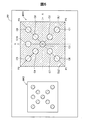
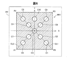
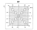
図5〜図8は、紙面PPに印刷された2次元の実物マーカーを示す。図5には、本実施形態のキャリブレーションに用いられる2つのマーカーとしての実物マーカーMK1,MK2が示されている。図5に示すように、実物マーカーMK1は、4つの頂点P0,P1,P2,P3を直線で結んだ正方形の中に、10個の正円を含むマーカーである。10個の円の内の5個の円は、頂点P0と頂点P2とを結んだ対角線CL1上に円の中心が存在する。当該5個の円は、対角線CL1に沿って、頂点P0に近い円から、円C1,C2,C3,C4,C5である。同じように、10個の円の内の5個の円は、頂点P1と頂点P3とを結んだ対角線CL2上に円の中心が存在する。当該5個の円は、対角線CL2に沿って、頂点P1に近い円から、円C6,C7,C3,C8,C9である。円C3は、対角線CL1と対角線CL2との交点であると共に、正方形の重心である点を中心とする円である。10個の円の内の1個の円である円C10は、正方形の重心を通り、かつ、P1とP2とを結ぶ直線に平行なY軸上に中心を有する。円C10は、正方形の重心を通り、Y軸に直交するX軸に沿って、円C5および円C9と同じ位置に中心を有する。換言すると、円C10は、円C5の中心と円C9の中心との中間に中心を有する円である。 5 to 8 show a two-dimensional real marker printed on the paper surface PP. FIG. 5 shows real markers MK1 and MK2 as two markers used in the calibration of the present embodiment. As shown in FIG. 5, the real marker MK1 is a marker that includes ten perfect circles in a square connecting four vertices P0, P1, P2, and P3 with straight lines. Five of the ten circles have the center of the circle on the diagonal line CL1 connecting the vertex P0 and the vertex P2. The five circles are circles C1, C2, C3, C4, and C5 from the circle close to the vertex P0 along the diagonal line CL1. Similarly, five of the ten circles have the center of the circle on the diagonal line CL2 connecting the vertex P1 and the vertex P3. The five circles are circles C6, C7, C3, C8, and C9 from the circle close to the vertex P1 along the diagonal line CL2. The circle C3 is a circle centered on a point that is the intersection of the diagonal line CL1 and the diagonal line CL2 and the center of gravity of the square. A circle C10, which is one of the ten circles, has a center on the Y axis that passes through the center of gravity of the square and is parallel to a straight line connecting P1 and P2. The circle C10 passes through the center of gravity of the square and has a center at the same position as the circles C5 and C9 along the X axis orthogonal to the Y axis. In other words, the circle C10 is a circle having a center between the center of the circle C5 and the center of the circle C9.
本実施形態では、対角線CL1上に中心を有する5個の円における隣接する円の中心間の距離は、同じ距離になるように設定されている。同じように、対角線CL2上に中心を有する5個の円における隣接する円の中心間の距離は、同じ距離になるように設定されている。また、対角線CL1に中心を有する隣接する円の中心間の距離と、対角線CL2に中心を有する隣接する円の中心間の距離とは、同じ距離である。なお、10個の内の円C10のみ、他の円との中心間との距離が異なる。10個の円の大きさは、同じ大きさである。なお、対角線CL1、対角線CL2、X軸、およびY軸は、実物マーカーMK1を説明するために、便宜上、図5に示しているのであり、実際の実物マーカーMK1には含まれない直線である。 In the present embodiment, the distance between the centers of adjacent circles in the five circles having the center on the diagonal line CL1 is set to be the same distance. Similarly, the distance between the centers of adjacent circles in the five circles having the center on the diagonal line CL2 is set to be the same distance. The distance between the centers of adjacent circles having the center on the diagonal line CL1 and the distance between the centers of adjacent circles having the center on the diagonal line CL2 are the same distance. Note that only the circle C10 out of 10 has a different distance from the center with respect to other circles. The ten circles have the same size. Note that the diagonal line CL1, the diagonal line CL2, the X axis, and the Y axis are shown in FIG. 5 for the sake of convenience in order to describe the real marker MK1, and are straight lines not included in the actual real marker MK1.
図5では、色の違いを、ハッチングを変えることで表している。具体的には、図5におけるハッチングが施された部分は、黒色であり、その他の部分は、白色である。そのため、図5に示すように、実物マーカーMK1は、白色の紙面PPに、白色によって周囲が囲まれた黒色の正方形によって形成され、その正方形の中に10個の円が白色で形成されている。 In FIG. 5, the difference in color is represented by changing the hatching. Specifically, the hatched portion in FIG. 5 is black, and the other portions are white. Therefore, as shown in FIG. 5, the real marker MK1 is formed on the white paper PP by a black square surrounded by white, and 10 circles are formed in white in the square. .
図5に示す実物マーカーMK2は、実物マーカーMK1を元に作成されたマーカーである。実物マーカーMK2は、実物マーカーMK1の大きさを縮小させ、かつ、黒色と白色との反転させたマーカーである。そのため、図5に示すように、実物マーカーMK2は、黒色によって周囲が囲まれた白色の正方形によって形成され、その正方形の中に10個の円が黒色で形成されている。本実施形態では、マーカー画像記憶部138は、実物マーカーMK1の2次元の画像であるマーカー画像IMGを記憶している。なお、実物マーカーMK2は、図6に示すように、実物マーカーMK1から分離されていてもよい。また、図7に示すように、実物マーカーMK2(MK1)に代えて、対角線上にない円を省略された実物マーカーMK1Aが採用されてもよい。なお、図8に示すように、実物マーカーMK1,MK2,MK1Aの裏面には、形状、模様、または色彩の特徴は必要ない。
A real marker MK2 shown in FIG. 5 is a marker created based on the real marker MK1. The real marker MK2 is a marker in which the size of the real marker MK1 is reduced and black and white are inverted. Therefore, as shown in FIG. 5, the real marker MK2 is formed by a white square surrounded by black, and ten circles are formed in black in the square. In the present embodiment, the marker
図4に示すCPU140は、ROM121に格納されているプログラムを、RAM122に展開することにより、オペレーティングシステム150(OS150)、表示制御部190、音声処理部170、画像処理部160、表示設定部165、マーカー特定部166、およびパラメーター設定部167として機能する。
4 expands the program stored in the
表示制御部190は、右表示駆動部22および左表示駆動部24を制御する制御信号を生成する。表示制御部190は、右表示駆動部22および左表示駆動部24のそれぞれによる画像光の生成および射出を制御する。表示制御部190は、右LCD制御部211と左LCD制御部212とに対する制御信号のそれぞれを、送信部51および52を介して送信する。また、表示制御部190は、右バックライト制御部201と左バックライト制御部202とに対する制御信号のそれぞれを送信する。
The
画像処理部160は、コンテンツに含まれる画像信号を取得し、送信部51,52を介して、取得した画像信号を画像表示部20の受信部53,54へと送信する。音声処理部170は、コンテンツに含まれる音声信号を取得し、取得した音声信号を増幅して、連結部材46に接続された右イヤホン32内のスピーカー(図示しない)および左イヤホン34内のスピーカー(図示しない)に対して供給する。
The
表示設定部165は、マーカー画像記憶部138に記憶されたマーカー画像IMGを右光学像表示部26または左光学像表示部28に表示させる。表示設定部165は、キャリブレーションが実行されているとき(キャリブレーション実行時)に、操作部135が受け付けた操作に基づいて、マーカー画像IMGを右光学像表示部26に表示する場合と、マーカー画像IMGを左光学像表示部28に表示する場合とを制御する。表示設定部165は、カメラ60が実物マーカーMK1を撮像してキャリブレーションを実行するときと、カメラ60が実物マーカーMK2を撮像してキャリブレーションを実行するときとで異なる大きさのマーカー画像IMGを右光学像表示部26または左光学像表示部28に表示させる。また、表示設定部165は、キャリブレーション実行時に、後述する文字画像等を光学像表示部26,28に表示させる。
The
マーカー特定部166は、カメラ60によって撮像された撮像画像の中に実物マーカーMK1,MK2が印刷された紙面PPが含まれる場合に、撮像された紙面PPから、実物マーカーMK1,MK2を特定する。実物マーカーMK1,MK2を特定するための具体的な処理については、後述するが、マーカー特定部166は、実物マーカーMK1,MK2の4つの頂点、10個の円の中心の座標値を抽出することで、撮像画像の中から実物マーカーMK1,MK2を特定する。マーカー特定部166は、例えば、撮像画像の色の階調値を2値化することで、実物マーカーMK1,MK2における白色と黒色との部分を区別して、円の中心の座標を抽出する。
The
パラメーター設定部167は、カメラ60によって撮像された特定のオブジェクト(以下、「特定オブジェクト」ともいう)に対応付けられた状態で光学像表示部26,28に表示されるAR(Augmented Reality)画像の表示領域内での位置などを設定するために必要なパラメーター群を設定する。具体的には、パラメーター設定部167は、光学像表示部26,28に表示されるAR画像の位置と大きさと向きと奥行感との少なくとも1つと、特定オブジェクトの位置と大きさと向きと奥行感との1つと、が対応した状態のAR画像をユーザーに視認させるパラメーター群を設定する。換言すると、パラメーター設定部167は、カメラ60に原点が固定された3次元座標系(3D)と、光学像表示部26,28の表示領域(2D)とを対応付けるためのパラメーター群の少なくとも1つを、キャリブレーションによって算出する。なお、以降では、カメラ60に原点が固定された3次元座標系をカメラ座標系と呼ぶ。本実施形態では、カメラ座標系以外の座標系として、実物マーカーMK1または実物マーカーMK2の原点を基準とする実物マーカー座標系、特定オブジェクトを基準とするオブジェクト座標系、右光学像表示部26の原点または左光学像表示部28の原点を基準とする表示部座標系などを定義する。
The
ここで、パラメーター群は、「検出系パラメーターセット」と、「表示系パラメーターセット」と、を含む。「検出系パラメーターセット」は、カメラ60に関するカメラパラメーターを含む。「表示系パラメーターセット」は、カメラ60と光学像表示部26,28との間の空間関係を表す3Dから3Dへの「変換パラメーター」と、任意の3Dモデル(3次元座標で表されたCGモデル)を画像(つまり2D)として表示するための3Dから2Dへの「写像パラメーター」と、を含む。これらのパラメーターは、必要に応じて行列またはベクトルの態様で表される。「1つのパラメーター」との表記は、1つの行列または1つのベクトルを示すこともあるし、1つの行列またはベクトルに含まれる複数の要素の1つを示すこともある。パラメーター設定部167は、パラメーター群のうち、必要なパラメーターを導出し、AR画像の表示の際に用いる。この結果、HMD100は、ユーザーに、画像表示部20を介して、AR画像(ARモデル)の位置、大きさ、向き、奥行感の少なくとも1つと、特定オブジェクトのそれらと、がほぼ一致する状態で当該AR画像を視認させることができる。もちろん、これらに加えて、HMD100は、色やテクスチャーなどの見え方が互いに一致するようにしてもよい。
Here, the parameter group includes a “detection system parameter set” and a “display system parameter set”. The “detection system parameter set” includes camera parameters related to the
表示設定部165は、キャリブレーションが実行されているときに、AR画像または設定画像SIM(後述)を右光学像表示部26または左光学像表示部28に表示させる。設定画像SIMを用いた詳細な処理については後述する。
The
インターフェース180は、制御部10に対して、コンテンツの供給元となる種々の外部機器OAを接続するためのインターフェースである。外部機器OAとしては、例えば、ARシナリオを記憶している記憶装置、パーソナルコンピューター(PC)や携帯電話端末、ゲーム端末等、がある。インターフェース180としては、例えば、USBインターフェース、マイクロUSBインターフェース、メモリーカード用インターフェース等を用いることができる。
The
図4に示すように、画像表示部20は、右表示駆動部22と、左表示駆動部24と、右光学像表示部26としての右導光板261と、左光学像表示部28としての左導光板262と、を備えている。
As shown in FIG. 4, the
右表示駆動部22は、受信部53(Rx53)と、光源として機能する右バックライト制御部201(右BL制御部201)および右バックライト221(右BL221)と、表示素子として機能する右LCD制御部211および右LCD241と、右投写光学系251と、を含んでいる。右バックライト制御部201と右バックライト221とは、光源として機能する。右LCD制御部211と右LCD241とは、表示素子として機能する。
The right
受信部53は、制御部10と画像表示部20との間におけるシリアル伝送のためのレシーバーとして機能する。右バックライト制御部201は、入力された制御信号に基づいて、右バックライト221を駆動する。右バックライト221は、例えば、LEDやエレクトロルミネセンス(EL)等の発光体である。右LCD制御部211は、画像処理部160および表示制御部190から送信された制御信号に基づいて、右LCD241を駆動する。右LCD241は、複数の画素をマトリックス状に配置した透過型液晶パネルである。
The receiving
右投写光学系251は、右LCD241から射出された画像光を平行状態の光束にするコリメートレンズによって構成される。右光学像表示部26としての右導光板261は、右投写光学系251から出力された画像光を、所定の光路に沿って反射させつつユーザーの右眼REに導く。なお、左表示駆動部24は、右表示駆動部22と同様の構成を有し、ユーザーの左眼LEに対応するため、説明を省略する。
The right projection
図9は、IMU71における融合部300を示す。融合部300は、IMU71の外部にあってもよい。融合部300は、拡張カルマンフィルター(EKF)に基づいて、内部の各センサーの計測(値または信号)を融合する。本実施形態では、IMU配向は、4元数により表記される。4元数による表記は、回転行列へ変換可能である。拡張カルマンフィルターは、以下のように表される状態ベクトルに適用される。
X=[qs2w,bgyro]・・・(a)
FIG. 9 shows the
X = [q s2w , b gyro ] (a)
制御入力ベクトルは、ジャイロセンサーの入力によって決定される。
u=[ws]・・・(b)
インターバルΔtの間のK−1からKへ状態遷移モデルは、次式のように表される。
xk=f(xk-1,uk-1,wk-1)・・・(c)
wk-1は、ノイズベクトルである。
The control input vector is determined by the input of the gyro sensor.
u = [w s ] (b)
A state transition model from K−1 to K during the interval Δt is expressed as the following equation.
x k = f (x k−1 , u k−1 , w k−1 ) (c)
w k−1 is a noise vector.
図9に示すように、融合部300は、測定部310と、予測部320と、更新部330と、重力キャンセル部340と、回転変換部350と、遅延器360とを含む。
As shown in FIG. 9, the
測定部310は、加速度センサーから出力された加速度と、磁気センサーから出力された地磁気の計測as k,ms kとの入力を受けることによって機能する。測定部310は、ローパスフィルター311,312を含む。ローパスフィルター311は、計測された加速度as kにおけるノイズを低減する。ローパスフィルター312は、計測された地磁気ms kにおけるノイズを低減する。
The
予測部320は、所定時間に亘って、IMU71によって検出された角速度ωs k-1を積分することによって、角度変化の量(または姿勢)を推定し、予測された角度変化(または姿勢)を、更新部330へ出力する。更新部330は、予測された角度変化(または姿勢)を用いて、計測されたものzk(加速度および地磁気)を、フィルターすなわち融合する。そうすると、融合されたIMU配向qs2w kが更新されて出力され、そして、融合されたIMU配向qs2w kが、次のサイクルのために、遅延器360を介して、予測部320へフィードバックされる。融合されたIMU配向qs2w kが計算されると、重力キャンセル部340による重力のキャンセルよって、IMU71の動的または線形な加速度aw kが計算される。
The
回転変換部350は、IMU配向qs2w kを受け取り、回転行列Rs2w kに変換し出力する。加速度センサーからの計測された加速度as kは、重力キャンセル部340に入力される。重力キャンセル部340は、回転行列Rs2w kで表されたIMU配向を用いて地球の重力加速度を打ち消し、重力加速度の成分を含まないIMU71の線形加速度aw kを計算して出力する。
上述した拡張カルマンフィルターに基づく検出値の融合のための調整は、HMD100を製造する工場で実施される。カメラ60及びIMU71のキャリブレーションも、HMD100を製造する工場で実施される。
Adjustment for fusion of detection values based on the above-described extended Kalman filter is performed in a factory that manufactures the
図10は、キャリブレーション処理を示すフローチャートである。この処理は、共同キャリブレーションを目的としている。共同キャリブレーションとは、変換行列Tcam2imuと変換行列Tcam2displayとをまとめて求めることである。変換行列Tcam2imuとは、カメラ60に固定された座標系からIMU71に固定された座標系への変換行列(つまり座標変換行列)である。変換行列Tcam2imuは、カメラ60とIMU71との間の空間関係を示す。添え字のcam2imuは、camera to imuを意味する。変換行列Tcam2imuを決定することを、IMU−カメラキャリブレーションとも呼ぶ。変換行列Tcam2imuは、第1の空間関係を表す。
FIG. 10 is a flowchart showing the calibration process. This process is aimed at joint calibration. The joint calibration is to obtain the transformation matrix T cam2imu and the transformation matrix T cam2display together. The transformation matrix T cam2imu is a transformation matrix (that is, a coordinate transformation matrix) from a coordinate system fixed to the
変換行列Tcam2displayは、カメラ60に固定された座標系から光学像表示部26,28に固定された座標系への変換行列である。変換行列Tcam2displayは、カメラ60と光学像表示部26,28との間の空間関係を示す。変換行列Tcam2displayを決定することを、OSTCキャリブレーションとも呼ぶ。変換行列Tcam2displayは、第2の空間関係を表す。
The transformation matrix T cam2display is a transformation matrix from the coordinate system fixed to the
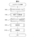
CPU140は、ユーザーからの指示を契機として、ROM121に格納されたプログラムを実行することで、キャリブレーション処理を実現する。キャリブレーション処理は、オフラインキャリブレーション(S600)と、回転データ収集処理(S700)と、アライメントデータ収集処理(S800)と、算出処理(S900)と、改善処理(S1000)とから構成される。S700,S800、S900及びS1000は、オンラインキャリブレーションのための処理である。
The
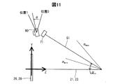
図11は、オフラインキャリブレーションにおいて、モデル化された空間関係を示す。光学像表示部26,28に直交する方向をZ方向と定義し、外部からユーザーへの眼への向きをZ方向プラス向きと定義する。保持部21,23は、Z軸上に配置される。X方向は、保持部21,23と装着基部91との回転軸と平行な方向である。X方向プラス向きは、保持部21,23と装着基部91との間の回転角(以下、角度α)が大きくなる向きに回転すると右ねじが進む向きである。Y方向は、X方向およびZ方向から定まる。
FIG. 11 shows the modeled spatial relationship in off-line calibration. The direction orthogonal to the optical
カメラ60は、回転できる。カメラ60の回転軸は、X軸と平行である。この回転によって、カメラ60が最も上を向いた位置を、位置0と呼ぶ。カメラ60が上を向くとは、右ねじがX方向プラス向きに進むように回転する向きに、カメラ60を回転させることで実現される移動のことである。一方、カメラ60が最も下を向いた位置を、位置1と呼ぶ。カメラ60が下を向くことは、カメラ60が上を向くことの逆のことである。位置0を基準とした回転角を、角度θと呼ぶ。このため、位置0における角度θは、0度である。本実施形態においては、位置1における角度θは、28度である。
The
S600は、オフラインキャリブレーションなので、工場において出荷前に実施される。S600は、空間関係と制約条件とを探索するために実施される。以下の3つの内容は、固定されているか、CADモデル、製造仕様から既知である。
IMU71とカメラ60との並進位置の関係
装着基部91上のIMU71の位置
HMD100上の右光学像表示部26と左光学像表示部28との位置
Since S600 is offline calibration, it is performed at the factory before shipment. S600 is implemented to search for spatial relationships and constraints. The following three contents are fixed or known from CAD models and manufacturing specifications.
Relationship between Translation Position of
先述したように、HMD100は、以下の可動を実現する。
装着基部91及びIMU71に対して、カメラ60は回転可能である。
保持部21,23に対して、装着基部91は傾斜可能である。
保持部21,23に対して、光学像表示部26,28は、上下(Y方向)に動き得る。
As described above, the
The
The mounting
The optical
次のように空間関係をモデル化する。
カメラ60とIMU71との間は、角度θの関数である。
保持部21,23と装着基部91との間、または保持部21,23とIMU71との間は、角度αの関数である。
保持部21,23と、光学像表示部26,28の2つの両端位置との間は、光学像表示部26,28のY座標値の関数である。
Model the spatial relationship as follows:
Between the
Between the holding
Between the holding
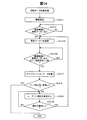
図12は、オフラインキャリブレーション(S600)を示すフローチャートである。まず、IMU71に対するカメラ60の回転についてのキャリブレーション(IMU−カメラキャリブレーション)を実行する(S610)。カメラ60とIMU71との間の回転位置(角度θ)は、変わり得る。なぜなら、先述したように、IMU71は装着基部91に固定されている一方で、カメラ60は28度まで一軸の回りで動くことができるからである。
FIG. 12 is a flowchart showing offline calibration (S600). First, calibration for the rotation of the
IMU−カメラキャリブレーションツールボックス、例えば、InerVis Toolboxを用いて、IMU71に対するカメラの空間関係を調整(キャリブレート)し、カメラ60の回転位置を離散的に求める。
Using the IMU-camera calibration tool box, for example, InerVis Toolbox, the spatial relationship of the camera with respect to the
カメラ60の角度範囲の学習として、カメラが2つの両端(位置0及び位置1)にあるときにIMU−カメラキャリブレーションを実行する。
As learning of the angle range of the
位置0にあるときのIMU71−カメラ60の間の回転を4元数表現でq0であるとし、位置1にあるときのIMU71−カメラ60の間の回転を4元数表現でq1であるとすると、これら2つの位置の間の回転変化は、次式で表される。
q=q0 -1q1・・・(d)及び
q=qw+qxi+qyj+qzk・・・(e)
The rotation between the
q = q 0 -1 q 1 ... (d) and
q = q w + q x i + q y j + q z k (e)
カメラ60に対するIMU71の回転の範囲は、θ=2acos(qw)である。回転の中心軸を単位ベクトルで表すと、次式になる。
[ux,uy,uz]=[qx,qy,qz]/√(qx 2+qy 2+qz 2)・・・(f)
そうすると、カメラ60に対するIMU71の配向の位置0と位置1との間の任意のカメラの角度は、以下の補間式によって得られる。
qcam2imu(tθ)=q0 -1q(tθ),t∈[0,1]・・・(g)
q(tθ)=cos(tθ/2)+{sin(tθ/2)}(uxi+uyj+uzk)・・・(h)
The range of rotation of the
[u x , u y , u z ] = [q x , q y , q z ] / √ (q x 2 + q y 2 + q z 2 ) ... (f)
Then, an arbitrary camera angle between the position 0 and the position 1 of the orientation of the
q cam2imu ( tθ ) = q 0 -1 q (tθ), t∈ [0,1] ・ ・ ・ (g)
q (tθ) = cos (tθ / 2) + {sin (tθ / 2)} (u x i + u y j + u z k) (h)
S620〜S670は、変換行列Timu2d0(α)を推定するためのステップである。変換行列Timu2d0(α)は、IMU71の座標系から、デフォルト位置d0における光学像表示部26,28の座標系への変換行列である。変換行列Timu2d0(α)は、角度αで決定される。先述したように角度αは、[αmin,αmax]の範囲内で可変である。
S620 to S670 are steps for estimating the transformation matrix T imu2d0 (α). The transformation matrix T imu2d0 (α) is a transformation matrix from the coordinate system of the
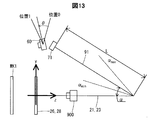
図13は、S620〜S670を実行するための装置構成を示す。図13は、図11を基礎にした図である。図11の内容に追加されたのは、実物マーカーMK1とカメラ900とである。図13に示された構成においては、保持部21,23は三脚に固定されており、光学像表示部26,28はデフォルト位置d0に配置されている。なお、三脚が鉛直に立っているとは限らない。三脚が鉛直に立っていなければ、保持部21,23は水平にはならない。
FIG. 13 shows an apparatus configuration for executing S620 to S670. FIG. 13 is a diagram based on FIG. What is added to the content of FIG. 11 is the real marker MK1 and the
S620では、実物マーカーMK1をアライメントする。ユーザーは、光学像表示部26,28の背後に設置されたカメラ900によって観察できる画像を見て、光学像表示部26,28に表示されたマーカー画像と、実物マーカーMK1とが重畳して見えるように、実物マーカーMK1の配置を決定する。この配置は、光学像表示部26,28と実物マーカーMK1とが平行であることを条件とする。アライメントが成立した後でも、マーカー画像の表示を続ける。
In S620, the real marker MK1 is aligned. The user sees an image that can be observed by the
次に、装着基部91の位置(角度α)を変化させる(S630)。本実施形態においては、ユーザーが、αmaxからαminへ向けて動かす。S630の間、CPU140が、IMU配向を順次、取得する(S640)。つまり、S640では、装着基部91の離散的な各位置(角度α)で、IMU配向が獲得され、ローカル世界座標系におけるIMU71の配向が計算される。
Next, the position (angle α) of the mounting
ここで、全体の計測は、S630における角度αの変化のさせ方から、装着基部91が光学像表示部26,28から最も遠い位置にある時刻tminから始まり、最も近い位置にある時刻tmaxで終わる。IMU71の配向は、次の集合として取得される。
Rimu2world(tmin)・・・Rimu2world(ti)・・・Rimu2world(tmax)・・・(i)
Here, the entire measurement starts from the time t min when the mounting
R imu2world (t min ) ・ ・ ・ R imu2world (t i ) ・ ・ ・ R imu2world (t max ) ・ ・ ・ (i)
そして、S630の間、CPU140が、カメラ60によって、実物マーカーMK1を撮像する(S650)。S650の間、カメラは、位置0若しくは位置1又はその両方の位置にある。つまり、S630の間、カメラ60を位置0及び位置1の何れかに固定し、連続的に撮像を実行する。位置0及び位置1の両方の位置で撮像を実行するためには、S630を2回、実行する。
Then, during S630, the
次に、CPU140が、各サンプリング位置における角度αを計算する(S660)。角度αは、Rimu2world(ti)及びRimu2world(tmin)の角度差として計算される。ここで、次に列挙する各式が成立し、角度αが求まる。
αmin=0・・・(j)
…
αi=acos([trace{Rimu2world(tmin)-1*Rimu2world(ti)}-1]/2)・・・(k)
…
αmax=acos([trace{Rimu2world(tmin)-1*Rimu2world(tmax)}-1]/2)・・・(l)
Next, the
α min = 0 ... (j)
...
α i = acos ([trace {R imu2world (t min ) -1 * R imu2world (t i )}-1] / 2) ... (k)
...
α max = acos ([trace {R imu2world (t min ) -1 * R imu2world (t max )}-1] / 2) ... (l)
次に、CPU140が、変換行列Timu2d0(α)を計算する(S670)。変換行列Timu2d0(α)は、次式によって計算できる。
Timu2d0(αi)=Tmaker2displayTcam2marker(αi)Timu2cam・・・(m)
Tmaker2displayは、S620において表示されるマーカー画像の姿勢として、予め定めされた姿勢を表す行列である。Tcam2markerは、撮像画像の処理から推定される実物マーカーMK1の姿勢を表す行列である。Timu2camは、位置0又は位置1におけるIMU−カメラキャリブレーションのパラメーターを表す行列である。位置0及び位置1は、S610において決定されている。
Next, the
T imu2d0 (α i ) = T maker2display T cam2marker (α i ) T imu2cam・ ・ ・ (m)
T maker2display is a matrix representing a predetermined posture as the posture of the marker image displayed in S620. T cam2marker is a matrix representing the posture of the real marker MK1 estimated from the processing of the captured image. Timu2cam is a matrix representing IMU-camera calibration parameters at position 0 or position 1. Position 0 and position 1 are determined in S610.
次に、CPU140が、モデルフィッティングを行う(S680)。このモデルフィッティングでは、αとTimu2d0との関係をモデル化する。つまり、αの関数としてのTimu2d0を決定する。S680では、各サンプリング点(離散的に取得された各角度α)についてのIMU71の配向α(S660)と変換行列Timu2d0の計算結果(S670)とを用いる。このように、S680では実測値を用いるため、モデルフィッティングは、完全ではなく、おおよそのものとなる。
Next, the
S680では、例えば、以下に列挙する関係を用いる。
Timu2d0(αi)=[q(αi),t(αi)]・・・(n)
なお、前式に含まれるq(αi)は回転の成分であり、t(αi)は並進の成分である。
角度αの回転軸[Ux,Uy,Uz]・・・(o)
前式の[Ux,Uy,Uz]はベクトルである。
qimu2display(αi)=q0q(αi)・・・(p)
前式の場合、光学像表示部26,28が地表に対して垂直でなくてもよい。つまり、Y方向が鉛直方向に一致していなくてもよい。さらに言い換えると、Z方向が水平でなくてもよい。
tx(αi)=tx(0)・・・(q)
ty(αi)=ty(0)+Lsin(α)・・・(r)
前式の場合、光学像表示部26,28が地表に対して垂直であることを仮定している。前式に含まれるLは、図13に示されるように、IMU71から回転中心までの距離である。ここでいう回転中心とは、保持部21,23と装着基部91との回転の中心である。
tz(αi)=tz(0)+L{1-cos(α)}・・・(s)
前式の場合、光学像表示部26,28が地表に対して垂直でなくてもよい。
α=kαi+b・・・(t)
前式に含まれるk及びbは、モデルフィッティングにより解かれる。
In S680, for example, the relationships listed below are used.
T imu2d0 (α i ) = [q (α i ), t (α i )] ... (n)
Note that q (α i ) included in the previous equation is a rotation component, and t (α i ) is a translation component.
Rotation axis of angle α [U x , U y , U z ] (o)
[Ux, Uy, Uz] in the previous equation is a vector.
q imu2display (α i ) = q 0 q (α i ) ・ ・ ・ (p)
In the case of the previous formula, the optical
t x (α i ) = t x (0) (q)
t y (α i ) = t y (0) + Lsin (α) (r)
In the case of the previous equation, it is assumed that the optical
t z (α i ) = t z (0) + L {1-cos (α)} ・ ・ ・ (s)
In the case of the previous formula, the optical
α = kα i + b (t)
K and b included in the previous equation are solved by model fitting.
変換行列Timu2d0と角度αとの間の関係は、ルックアップテーブル(LUT)によっても表記され得る。角度αに対応する変換行列Timu2d0は、LUTにおけるサンプリング値の線形補間により計算され得る。 The relationship between the transformation matrix T imu2d0 and the angle α can also be expressed by a lookup table (LUT). The transformation matrix T imu2d0 corresponding to the angle α can be calculated by linear interpolation of sampling values in the LUT.
次に、CPU140が、光学像表示部26,28の変位を求める(S690)。光学像表示部26,28は、保持部21,23に対する移動として、Y軸に沿った上下動しかしない。デフォルト位置d0に対する光学像表示部26,28の変位を変位dと表記すると、変位dは、以下によって直接にモデル化され得る。
Next, CPU140 calculates | requires the displacement of the optical
オフラインキャリブレーションが終わると、図10に示すように、回転データ収集処理が実行される(S700)。 When the offline calibration is finished, as shown in FIG. 10, a rotation data collection process is executed (S700).
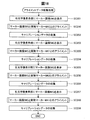
図14は、回転データ収集処理を示すフローチャートである。回転データ収集処理は、CPU140によって実行される。初めに、マーカー特定部166が撮像を開始する(SC211)。マーカー特定部166は、カメラ60が撮像した各撮像フレームに対して、2値化を実行して、実物マーカーMK2を抽出する。マーカー特定部166は、撮像範囲の中に、実物マーカーMK2があるか否かを判定する(SC212)。マーカー特定部166は、撮像範囲の中に実物マーカーMK2がないと判定した場合には(SC212,NO)、引き続き、撮像範囲の中から実物マーカーMK2の抽出を試行する。
FIG. 14 is a flowchart showing the rotation data collection process. The rotation data collection process is executed by the
マーカー特定部166は、撮像範囲の中に、実物マーカーMK2があると判定した場合には(SC212,YES)、カメラ60に対する実物マーカーMK2の位置と姿勢を導出し、それらの追跡を開始する(SC212A)。
When it is determined that the real marker MK2 is in the imaging range (SC212, YES), the
SC212Aの後で、パラメーター設定部167は、カメラ60の撮像範囲に実物マーカーMK2が存在している状態であり、かつ、ユーザーの頭部が所定期間、例えば2秒、に亘って安定的な状態か否かを判定する(SC215B)。頭部が安定的な状態であるとは、頭部の移動が停止していることを意味する。パラメーター設定部167がカメラ60の撮像範囲に実物マーカーが存在する状態であり、かつ、ユーザーの頭部が2秒間に亘って安定的な状態であると判定した場合には(SC215B,YES)、処理はSC217へ移行する。SC215Bの判定が「否」である場合には、この判定が満足されるまで、パラメーター設定部167は、撮像画像とユーザーの頭部の動きとを継続的に監視する。
After SC212A, the
パラメーター設定部167は、カメラ60による実物マーカーMK2の撮像画像及びIMU配向を、キャリブレーションデータとして取得する(SC217)。取得される撮像画像は1フレームであってもよいし、連続する複数フレームであってもよい。複数フレームが取得される場合には、パラメーター設定部167は、当該複数フレームに基づいたフィルタ処理を行うことにより、上述の円1〜9の中心座標の導出において、頭部の微小な動きの影響を低減することができる。
The
頭部が安定な状態にあるか否か、または実質的に静止しているか否かは、パラメーター設定部167が、カメラ60の撮像画像における実物マーカーMK2の特徴点の位置、IMU71の出力、およびこれらの組み合わせから判定できる。
Whether the head is in a stable state or substantially stationary is determined by the
次に、キャリブレーションデータを既に2回、取得したかを判定する(SC218)。1回しか取得していない場合(SC218,NO)、ユーザーに頷く動作を催促する(SC219)。この催促は、具体的には、音声や画像表示によって実行される。 Next, it is determined whether the calibration data has already been acquired twice (SC218). If it has been acquired only once (SC218, NO), the user is prompted to move (SC219). Specifically, this prompting is executed by voice or image display.
そして、頷きが開始されたかを判定する(SC219A)。この判定は、頭部が安定な状態にあるかの判定と同様、パラメーター設定部167が、カメラ60の撮像画像における実物マーカーMK2の特徴点の位置、IMU71の出力、およびこれらの組み合わせに基づき実行される。
Then, it is determined whether the whistle has started (SC219A). This determination is performed by the
頷きが開始されていない場合(SC219A,NO)、SC219を繰り返し実行する。頷きが開始された場合(SC219A,YES)、SC212Aに戻り、SC212A〜SC218を再び実行する。 If sowing has not started (SC219A, NO), SC219 is repeatedly executed. If sowing is started (SC219A, YES), the process returns to SC212A, and SC212A to SC218 are executed again.
2回目にSC218の判定を実行する場合には、キャリブレーションデータを既に2回、取得したと判定することになり(SC218,YES)、回転データ収集処理を終える。 When the determination of SC218 is executed for the second time, it is determined that the calibration data has already been acquired twice (SC218, YES), and the rotation data collection process ends.
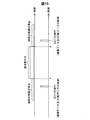
図15は、回転データ収集処理のタイミングチャートである。図15は、図14と共に説明したように、頷き動作の前後それぞれにおいて、動作の停止中にデータが収集されていることを示している。1回目のSC217の時点においては、実物マーカーMK2に対するカメラ60の相対位置が第1の位置である。2回目のSC217の時点においては、上記相対位置が第2の位置である。回転データ収集処理において用いられる実物マーカーMK2は、第1の実物マーカーである。
FIG. 15 is a timing chart of the rotation data collection process. FIG. 15 shows that data is being collected while the operation is stopped before and after the whispering operation, as described in conjunction with FIG. At the time of the first SC217, the relative position of the
回転データ収集処理を終えると、図10に示すように、アライメントデータ収集処理を実行する(S800)。 When the rotation data collection process is completed, the alignment data collection process is executed as shown in FIG. 10 (S800).
図16は、アライメントデータ収集処理を示すフローチャートである。アライメントデータ収集処理では、パラメーター設定部167が、右光学像表示部26に関するアライメントを成立させた状態でキャリブレーションデータを収集し、左光学像表示部28に関するアライメントを成立させた状態でキャリブレーションデータを収集する。
FIG. 16 is a flowchart showing alignment data collection processing. In the alignment data collection process, the
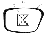
アライメントデータ収集処理では、初めに、表示設定部165が右光学像表示部26にマーカー画像IMGを表示させる(SC201)。図17は、マーカー画像IMGが表示された場合の右光学像表示部26のイメージ図である。図17に示すように、表示設定部165は、マーカーの正方形の外枠と、正方形の中に含まれる10個の円の外枠と、を右光学像表示部26に表示させる。表示設定部165は、マーカー画像IMGを、赤色の線として右光学像表示部26に表示させる。なお、図17では、画像表示部20の内の右光学像表示部26以外の部分の図示を省略する。
In the alignment data collection process, first, the
右光学像表示部26にマーカー画像IMGが表示されると、パラメーター設定部167は、マーカー画像IMGと実物マーカーMK2とが一致して視認されるように、HMD100を装着したままユーザーに位置と姿勢を合わせることを促す(SC210)。
When the marker image IMG is displayed on the right optical
右光学像表示部26にはさらにメッセージが表示されてもよい。HMD100は、ユーザーがマーカー画像IMGと実物マーカーMK2とが一致するように視認した場合に、ユーザーは、タッチパッドの操作、ボタンの押下、または音声コマンドの発声をするように指示する。パラメーター設定部167がこれら操作または音声コマンドを受け付けた場合に、カメラ60が実物マーカーMK2を撮像、すなわちキャリブレーションデータの収集をする(SC202)。音声コマンドに基づいて、パラメーター設定部167がキャリブレーションデータを収集する場合には、ユーザーの頭部の動きが少ないことが期待される。そのため、音声コマンドに基づく操作では、タッチ操作やボタンの押下の場合に比べて、ユーザーが成立させたアライメントからのずれが少ない状態でのキャリブレーションデータの収集が可能となり、結果として、AR画像の重畳精度のよいHMD100が得られる。
A message may be further displayed on the right optical
SC210のマーカー画像IMGと実物マーカーMK2との位置と姿勢を合わせる処理(目視によるアライメント処理)およびキャリブレーションデータの収集が実行されると、表示設定部165は、SC201の処理と同じく図17に示すように、右光学像表示部26にマーカー画像IMGを表示させる(SC203)。その後、パラメーター設定部167は、マーカー画像IMGと実物マーカーMK1とが一致して視認されるように、HMD100を装着したままユーザーに位置と姿勢を合わせることを促す(SC220)。この状態で実物マーカーMK1が撮像されることで、パラメーター設定部167は、キャリブレーションデータを収集する(SC204)。ここで、実物マーカーMK1は、実物マーカーMK2よりも大きい。そのため、SC220の処理では、ユーザーがマーカー画像IMGと実物マーカーMK1とが一致するように視認する場合には、右光学像表示部26と実物マーカーMK1との距離は、実物マーカーMK2の場合と比べて大きくなる。
When processing for aligning the position and orientation of the marker image IMG of SC210 and the actual marker MK2 (visual alignment processing) and collection of calibration data are executed, the
パラメーター設定部167は、左光学像表示部28に関して、右光学像表示部26におけるSC201からSC204までの処理と同じ処理として、図16のSC205からSC208までの処理を実行し、アライメントデータ収集処理を終える。
The
図18は、アライメントデータ収集処理のタイミングチャートである。図18は、図16と共に説明したように、アライメントが成立した場合に、キャリブレーションデータ(撮像データ)が収集されていることを示している。アライメントデータ収集処理において用いられる実物マーカーMK1,MK2のそれぞれは、第2の実物マーカーである。 FIG. 18 is a timing chart of the alignment data collection process. FIG. 18 shows that calibration data (imaging data) is collected when alignment is established as described in conjunction with FIG. Each of the real markers MK1 and MK2 used in the alignment data collection process is a second real marker.
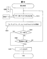
次に、図10に示すように、算出処理を実行する(S900)。図19は、算出処理を示すフローチャートである。まず、初期推定値[α0 θ0 d0]Tと、収集データとを基に、エラー値とヤコビ行列を計算する(S910)。収集データとは、回転データ収集処理によって収集されたデータと、アライメントデータ収集処理によって収集されたデータとのことである。以下、S910について説明を補足する。 Next, as shown in FIG. 10, a calculation process is executed (S900). FIG. 19 is a flowchart showing the calculation process. First, an error value and a Jacobian matrix are calculated based on the initial estimated value [α 0 θ 0 d 0 ] T and the collected data (S910). Collected data refers to data collected by the rotation data collection process and data collected by the alignment data collection process. Hereinafter, the description of S910 will be supplemented.
IMU-カメラキャリブレーションは、変換行列Tcam2imuの決定によって実現される。OSTCキャリブレーションは、変換行列Tcam2displayの決定によって実現される。Tcam2displayは、回転と並進とを含むカメラ60と光学像表示部26,28との間のパラメーターである。これら2つの変換行列を、角度θ、角度α及び変位dを用いて結合させると、共同キャリブレーションを実現するための次式が得られる。
Tcam2display=Td02d(d)T(imu2d0)(α)Tcam2imu(θ)・・・(u)
The IMU-camera calibration is realized by determining the transformation matrix T cam2imu . The OSTC calibration is realized by determining the transformation matrix T cam2display . T cam2display is a parameter between the
T cam2display = T d02d (d) T ( imu2d0 ) (α) T cam2imu (θ) (u)
角度θ、角度α及び変位dを、オフラインルックアップテーブルまたは次の関数によって決定する。
Tcam2imu=Tcam2imu(θ)・・・(v)
Timu2d0=Timu2d0(α)・・・(w)
Td02d=Td02d(d)・・・(x)
The angle θ, the angle α, and the displacement d are determined by an offline lookup table or the following function.
T cam2imu = T cam2imu (θ) (v)
T imu2d0 = T imu2d0 (α) ・ ・ ・ (w)
T d02d = T d02d (d) (x)
角度θ,角度αおよび変位dの初期推定値が与えられると、コスト関数を最適化するための最適な角度θ,角度αおよび変位dを見つけることができる。最適な角度θ,角度αおよび変位dが見つかると、式(u)に、式(v),式(w),式(x)を代入することで、次式が得られる。
Tcam2display=Td02dTimu2d0Tcam2imu・・・(y)
Given the initial estimates of angle θ, angle α, and displacement d, the optimal angle θ, angle α, and displacement d for optimizing the cost function can be found. When the optimum angle θ, angle α, and displacement d are found, the following equation is obtained by substituting the equations (v), (w), and (x) into the equation (u).
T cam2display = T d02d T imu2d0 T cam2imu (y)
コスト関数について説明する。まず、頷き(頭部の回転)がある場合と頭部の回転がない場合とを含む期間の一組の回転エラーは、次式で定義される。
Erot=Σ||ωc-Rimu2camωI||2・・・(z)
The cost function will be described. First, a set of rotation errors during a period including a case where there is a whisper (head rotation) and a case where there is no head rotation is defined by the following equation.
E rot = Σ || ω c -R imu2cam ω I || 2・ ・ ・ (z)
Rimu2camは、IMU座標系からカメラ座標系への回転行列である。前式におけるωc及びωIは何れも、回転データ収集処理における1回目のSC217の時点から、2回目のSC217の時点までにおけるHMD100の角速度ベクトルである。角速度ベクトルωcは、SC217において収集された撮像データから算出される。角速度ベクトルωIは、SC217において収集されたIMU配向から算出される。角速度ωIは、第1位置から第2の位置へのIMU71の動きを表す。
R imu2cam is a rotation matrix from the IMU coordinate system to the camera coordinate system. Both ω c and ω I in the previous equation are the angular velocity vectors of the
一方、左右の眼のアライメントエラーは、次式で定義される。次式については、後で説明を補足する。
Ealign=Σ||p-Proj(CP,Tcam2display)||2・・・(aa)
On the other hand, the alignment error between the left and right eyes is defined by the following equation. The following formula will be supplemented later.
E align = Σ || p-Proj (CP, T cam2display ) || 2・ ・ ・ (aa)
ここで、式(aa)に含まれる小文字のpは、アライメントデータ収集処理において収集された撮像データから得られる円1〜9の位置情報であり、イメージセンサーに固定された2次元の画像座標系で表されている。「Proj」は、モデルに原点が固定された3次元座標系で表されたモデルマーカーの円1〜9の位置を、当該3次元座標系から上記画像座標系へ写像変換する変換行列を意味する。ここで、当該写像変換のパラメーターは、カメラ60のカメラパラメーターCP、およびカメラ60と光学像表示部26,28との間の空間関係を表す変換行列Tcam2displayである。変換行列Tcam2displayは、式(u)〜式(y)により、角度θ、角度及び変位dから求められる。
Here, the small letter p included in the expression (aa) is position information of the circles 1 to 9 obtained from the imaging data collected in the alignment data collection process, and is a two-dimensional image coordinate system fixed to the image sensor. It is represented by “Proj” means a transformation matrix for mapping and converting the positions of the circles 1 to 9 of the model marker expressed in a three-dimensional coordinate system whose origin is fixed to the model from the three-dimensional coordinate system to the image coordinate system. . Here, the parameter of the mapping conversion is a camera parameter CP of the
共同推定(つまり共同キャリブレーション)のためのコスト関数は、次式のように定義される。λは、重み付けのための定数である。S910において計算されるエラー値とは、次式によって算出される左辺の値のことである。
E=Ealign+λErot・・・(bb)
The cost function for joint estimation (ie joint calibration) is defined as: λ is a constant for weighting. The error value calculated in S910 is the value on the left side calculated by the following equation.
E = E align + λE rot (bb)
そして、エラー値を用いて、以下のヤコビアン(ヤコビ行列)Jを計算する。
J=[∂E/∂α ∂E/∂θ ∂E/∂d]・・・(cc)
Then, the following Jacobian (Jacobi matrix) J is calculated using the error value.
J = [∂E / ∂α ∂E / ∂θ ∂E / ∂d] ・ ・ ・ (cc)
本実施形態では、ガウスニュートン法による繰り返し計算を用いて、コスト関数(エラー値)を最小化するために、キャリブレーションパラメーターを更新する(S920)。S920は、次式のように実行する。
[αn;θn;dn]=[αn-1;θn-1;dn-1]+inv(JTinv(JTJ)JTe・・・(dd)
前式における制約条件は、以下の通りである。
αmin<αn<αmax・・・(ee)
θmin<θn<θmax・・・(ff)
dmin<dn<dmax・・・(gg)
In the present embodiment, the calibration parameter is updated in order to minimize the cost function (error value) using iterative calculation by the Gauss-Newton method (S920). S920 is executed according to the following equation.
[α n ; θ n ; d n ] = [α n-1 ; θ n-1 ; d n-1 ] + inv (J T inv (J T J) J T e... (dd)
The constraint conditions in the previous equation are as follows.
α min <α n <α max (ee)
θ min <θ n <θ max (ff)
d min <d n <d max (gg)
式(dd)に含まれるeは、式(z)及び式(aa)それぞれのノルムの中身である。つまり、「ωc-Rimu2camωI」及び「p-Proj(P,Tcam2display)」である。 E contained in the formula (dd) is the content of the norm of each of the formula (z) and the formula (aa). That is, “ω c −R imu2cam ω I ” and “p-Proj (P, T cam2display )”.
続いて、算出したエラー値が基準値Te未満であるかを判定する(S930)。算出したエラー値が基準値Te以上の場合(S930,NO)、S910,S920の実行回数が上限値に達したかを判定する(S940)。S910,S920の実行回数が上限値に達していない場合(S940,NO)、S910,S920を再び実行する。 Subsequently, it is determined whether the calculated error value is less than the reference value Te (S930). If the calculated error value is greater than or equal to the reference value Te (S930, NO), it is determined whether the number of executions of S910 and S920 has reached the upper limit value (S940). When the number of executions of S910 and S920 has not reached the upper limit value (S940, NO), S910 and S920 are executed again.
一方、算出したエラー値が基準値Te未満の場合(S930,YES)、又はS910,S920の実行回数が上限値に達した場合(S940,YES)、現状の角度α、角度θ及び変位dの値、および/または式(u)〜式(y)の関係に基づいて変換パラメーターTcam2displayを出力して(S950)、算出処理を終える。 On the other hand, when the calculated error value is less than the reference value Te (S930, YES), or when the number of executions of S910 and S920 reaches the upper limit (S940, YES), the current angle α, angle θ, and displacement d The conversion parameter Tcam2display is output based on the value and / or the relationship between the expressions (u) to (y) (S950), and the calculation process is terminated.
パラメーターの改善処理(S1000):
次に、パラメーター設定部167が、S900によって導出されたカメラ60と光学像表示部との間の空間関係(変換パラメーターとも呼ぶ。Tcam2display)を改善する処理を説明する。本実施形態による改善処理では、上記空間関係の改善と併せて、カメラ60のカメラパラメーターが導出される。なお、他の実施形態の改善処理では、カメラパラメーターは、必ずしも最適化される必要がなく、設計値に固定されていてよい。ただし、以下に示す本実施形態では、ユーザーが必要に応じてカメラパラメーターを最適化することができるように、カメラパラメーターを最適化変数として含んだアルゴリズムを提示している。他の実施形態において、カメラパラメーターを最適化する必要がない場合には、これらを定数(固定値)として以下の式を扱えばよい。
Parameter improvement processing (S1000):
Next, a process in which the
カメラパラメーターについて:
カメラ60に関するカメラパラメーターとして、本実施形態では、4個のカメラパラメーター(fx、fy、Cx、Cy)が利用される。(fx、fy)は撮像部であるカメラ60の焦点距離であり、画素密度に基づいて画素数に換算されている。(Cx、Cy)は、カメラ主点位置と呼ばれ、撮像画像の中心位置を意味する。(Cx、Cy)は、例えばカメラ60のイメージセンサーに固定された2D座標系で表され得る。
About camera parameters:
In the present embodiment, four camera parameters (fx, fy, Cx, Cy) are used as camera parameters related to the
カメラパラメーターは、撮像部の主要部分を構成するカメラ60の製品仕様から知ることができる(以下ではこれをデフォルトカメラパラメーターとも表記する)。ただし、実際のカメラのカメラパラメーターがデフォルトカメラパラメーターから大きくずれていることが多い。しかも、同じ仕様のカメラであっても、製品が異なれば、製品ごとのカメラ間で、カメラパラメーターがばらついている(揃っていない)ことがある。
The camera parameters can be known from the product specifications of the
AR画像として光学像表示部26,28に表示されるARモデルにおける位置、大きさ、姿勢の少なくとも1つが実物体にアライン(重畳)するようにユーザーに視認させる場合、カメラ60は、当該実物体の位置および姿勢を検出する検出機として機能する。このとき、パラメーター設定部167は、カメラパラメーターを用いて、カメラ60に撮像された実物体のカメラ60に対する位置および姿勢を推定する。さらに、パラメーター設定部167は、当該位置および姿勢を、カメラ60と左光学像表示部28(右光学像表示部26)との間の相対位置関係を用いて、左光学像表示部28に対する実物体の位置および姿勢に変換する。さらに、パラメーター設定部167は、当該変換された位置および姿勢に基づいて、ARモデルの位置および姿勢を決定する。そして、画像処理部160は、当該位置および姿勢を有するARモデルを、写像パラメーターを用いて表示領域に写像(変換)し、表示バッファー(例えばRAM122)に書き込む。そして、表示制御部190は、表示バッファーに書き込まれたARモデルを左光学像表示部28に表示する。このため、カメラパラメーターがデフォルトカメラパラメーターである場合には、推定される実物体の位置および姿勢に誤差が含まれることとなる。そうすると、推定された位置および姿勢の誤差に由来して、表示されたARモデルと実物体との重畳に誤差があるようにユーザーに視認される。
When the user visually recognizes that at least one of the position, size, and orientation in the AR model displayed on the optical
そこで、本実施形態では、ARモデルが対象物に重畳してユーザーに視認されるようにするためのキャリブレーションの際に、パラメーター設定部167は、カメラパラメーターを、実物マーカーMK2および実物マーカーMK1の撮像データを用いて、最適化して設定する。そして、設定されたカメラパラメーターが用いられて、対象物の位置および姿勢が検出(推定)されるようにする。そうすれば、ARモデルの表示において、表示されるARモデルと実物体との間に発生するずれがユーザーに視認される度合いが低くなる。後述するように、同じHMD100のユーザーが同一人であっても、カメラパラメーターの設定は、キャリブレーションが実行されるごとに実行され、当該キャリブレーションに引き続いて行われる対象物とARモデルとの間での位置、大きさ、向きの少なくとも1つが一致した表示のために使用されることが好ましい。これは、キャリブレーションの際に、必ずしもユーザーは、実物マーカーMK2または実物マーカーMK1と、実物マーカーMK2または実物マーカーMK1に対応したマーカー画像IMGとを、同じ精度で位置および姿勢を合わせるとは限らないことによる。たとえユーザーが違う精度で位置および姿勢を合わせたとしても、それに応じたカメラパラメーターが設定されることから、実物体に対するARモデルの重畳表示がされる場合に重畳表示のずれの増大が抑制される。
Therefore, in the present embodiment, the
変換パラメーターについて:
HMD100は、カメラ60と光学像表示部26,28との間の相対位置関係が変化する構造を有する。デフォルトカメラパラメーターについての説明からも理解されるように、ARモデルにおける位置、大きさ、姿勢の少なくとも1つが実物体にアライン(重畳)するようにユーザーに視認させる場合、実際のカメラ60と光学像表示部26,28との間の相対位置関係とは異なる相対位置関係に基づいてARモデルを表示すると、表示されたARモデルと実物体との重畳に誤差が視認される。
About conversion parameters:
The
そこで、本実施形態では、ARモデルが対象物に重畳してユーザーに視認されるようにするためのキャリブレーションの際に、カメラ60の座標系と、右光学像表示部26の座標系および左光学像表示部28の座標系と、の間の相対位置関係(回転および並進の少なくとも1つ)を表す変換パラメーターを調整または設定する。そして、設定された当該変換パラメーターが表す空間関係(相対位置関係)を用いてARモデルの表示をすると、ユーザーにずれが視認される度合いが低くなる。
Therefore, in the present embodiment, in the calibration for superimposing the AR model on the object so as to be visually recognized by the user, the coordinate system of the
本実施形態では、パラメーター設定部167は、右光学像表示部26に対応する右変換パラメーター[Rcam2right,tcam2right]と、左光学像表示部28に対応する左変換パラメーター[Rcam2left,tcam2left]と、を設定する。回転行列Rcam2rightは、直交する3軸の回転によって決定される3つのパラメーターであり、並進行列tcam2rightは、3軸に沿った並進のそれぞれに対応する3つのパラメーターである。すなわち、右光学像表示部26に対応する右変換パラメーターPMRは、計6つのパラメーターを含んでいる。同じように、左光学像表示部28に対応する変換パラメーターは、回転行列Rcam2leftと並進行列Tcam2leftとであり、計6つのパラメーターを含んでいる。以上の通り、本実施形態では、カメラパラメーターに含まれる4個のパラメーターと、空間関係を表す12個の変換パラメーターとの16個のパラメーターが算出される。
In the present embodiment, the
パラメーター導出処理:
パラメーター設定部167は、アライメントデータ収集処理において取得された撮像画像に基づいて、後述の式(ss)を用いて、カメラパラメーターおよび変換パラメーターを算出する。本実施形態では、設定パラメーターを設定する場合の初期値(i=0)として、ステップS900で得られた変換パラメーターTcam2displayが用いられる。
Parameter derivation processing:
The
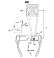
図20は、右光学像表示部26のみにマーカー画像IMGが表示された状態での空間的な位置関係を示す概略図である。図20には、ユーザーが、予めHMD100を装着したユーザーの仮想の右眼の位置として設定された右眼位置RPから、右光学像表示部26に表示されたマーカー画像IMGを視認した場合の概略が示されている。つまり、図20は、アライメントデータ収集処理におけるSC201又はSC203の様子を示す。なお、図20には、HMD100の内の画像表示部20のみを図示し、装着帯90や制御部10などについては図示を省略している。図20には、撮像される3次元空間である外景の座標軸を表す座標軸CD2と、座標軸CD2を投影した二次元画像の座標軸を表す座標軸CD1と、が示されている。ユーザーは、右光学像表示部26に表示されたマーカー画像IMGを、画像表示部20から距離L1離れた位置に存在する実物マーカーMK1として視認する。
FIG. 20 is a schematic diagram illustrating a spatial positional relationship in a state where the marker image IMG is displayed only on the right optical
図20に示すように、右光学像表示部26に表示されたマーカー画像IMGと、外景に含まれ前方に位置する実物マーカーMK1と、が位置、大きさ、向きが一致するようにユーザーが視認するとき(以下、ユーザーが右眼RE(左眼LE)でアライメントを成立させるときともいう)、座標系の間には、次式の関係が成り立つ。なお、以降では、右光学像表示部26ではなく、左光学像表示部28にマーカー画像IMGが表示された場合について説明する。
CP×[Ro2dl,to2dl]×ModelMatrix
=CP×[Rcam2left,tcam2left]×[Robj2cam,tobj2cam]×ModelMatrix・・・(hh)
As shown in FIG. 20, the user visually recognizes that the marker image IMG displayed on the right optical
CP × [R o2dl , t o2dl ] × ModelMatrix
= CP × [R cam2left , t cam2left ] × [R obj2cam , t obj2cam ] × ModelMatrix (hh)
ここで、左辺および右辺のCPは、カメラ60のカメラパラメーターである。[Ro2dl,to2dl]は、実オブジェクト(この場合、実物マーカーMK2または実物マーカーMK1)に固定された座標系から左光学像表示部28に固定された座標系への変換行列である。Ro2dlは、回転を表す3×3の行列である。to2dlは、並進を表す3×1の行列である。[Ro2dl,to2dl]は、左光学像表示部28に対する実オブジェクトの位置および姿勢を表している。ModelMatrixは、モデルマーカー上の任意の1点を表す3×1の行列である。モデルマーカーは、マーカー画像IMGが左光学像表示部28に表示される場合の基礎となる3次元データ(3次元モデル:ただし本実施形態では平面)である。[Ro2dl,to2dl]×ModelMatrixの表記は、次式の規則に従っている。
[Ro2dl,to2dr]×ModelMatrix=[Ro2dl]×ModelMatrix+[to2dl]・・・(ii)
前式の表記規則は、式(hh)の他の部分にも適用される。
Here, CPs on the left side and the right side are camera parameters of the
[R o2dl , t o2dr ] × ModelMatrix = [R o2dl ] × ModelMatrix + [t o2dl ] (ii)
The conventions of the previous formula apply to other parts of the formula (hh).
式(hh)の右辺における[Rcam2left,tcam2left]は、カメラ60の座標系から左光学像表示部28の座標系への変換行列である。当該変換行列は、パラメーター設定部167によって設定される複数の変換パラメーターで構成される。式(hh)の右辺における[Robj2cam,tobj2cam]は、実オブジェクト(実物マーカーMK2または実物マーカーMK1)の座標系からカメラ60の座標系への変換行列である。[Robj2cam,tobj2cam]は、カメラ60に対する実オブジェクトの位置および姿勢を表している。
[R cam2left , t cam2left ] on the right side of the expression (hh) is a conversion matrix from the coordinate system of the
式(hh)の関係から、左光学像表示部28について、マーカー画像IMGと実物マーカーMK2または実物マーカーMK1とのアライメントが成立しているとき、次の2つの式が成り立つ。
Robj2cam=inv(Rcam2left)*Ro2dl・・・(jj)
tobj2cam=inv(Rcam2left)*(to2dl-tcam2left)・・・(kk)
From the relationship of the expression (hh), when the alignment between the marker image IMG and the actual marker MK2 or the actual marker MK1 is established for the left optical
R obj2cam = inv (R cam2left ) * R o2dl (jj)
t obj2cam = inv (R cam2left ) * (t o2dl -t cam2left ) ・ ・ ・ (kk)
左眼LEのアライメントが成立すると仮定したとき、実物マーカーMK2または実物マーカーMK1のカメラ60に対する姿勢をモデルマーカーに適用すると、カメラ60の座標系に変換されたモデルマーカー上の任意の点は次式のPcl(Xcl,Ycl,Zcl)のようになる。
Pcl=[Xcl Ycl Zcl]T=Robj2cam×ModelMatrix+tobj2cam・・・(ll)
Assuming that the alignment of the left eye LE is established, if the posture of the real marker MK2 or the real marker MK1 with respect to the
P cl = [X cl Y cl Z cl ] T = R obj2cam × ModelMatrix + t obj2cam ... (ll)
式(jj)および式(kk)により、Robj2cam,tobj2camを消去すると式(ll)は次式のようになる。
Pcl=[Xcl Ycl Zcl]T
=inv(Rcam2left)(Ro2dl×ModelMatrix+to2dl-tcam2left)・・・(mm)
When R obj2cam and t obj2cam are eliminated by the formula (jj) and the formula (kk), the formula (ll) becomes the following formula.
P cl = [X cl Y cl Z cl ] T
= inv (R cam2left ) (R o2dl × ModelMatrix + t o2dl -t cam2left ) ・ ・ ・ (mm)
Ro2dlおよびto2dlは、実物マーカーMK2または実物マーカーMK1の座標系から左光学像表示部28の座標系への回転および並進である。本実施形態では、ユーザーが左光学像表示部28に表示されたマーカー画像IMGを実物マーカーMK2または実物マーカーMK1に位置合わせしたときに、Ro2dlおよびto2dlが所定の回転および並進となるように、マーカー画像IMGが左光学像表示部28上の所定位置(例えば中央)に所定の配向かつ所定の大きさで、固定されて表示される。tcam2leftは、カメラの座標系から左光学像表示部28の座標系への並進である。なお、Ro2dlは、次に示すように単位行列である。つまり、実物マーカーMK2または実物マーカーMK1の座標系から左光学像表示部28の座標系へ変換しても、回転は発生しない。
R o2dl and t o2dl are rotation and translation from the coordinate system of the real marker MK2 or the real marker MK1 to the coordinate system of the left optical
to2dl=[0 0 -a]T・・・(nn)
tcam2left=[D1 D2 D3]T・・・(oo)
t o2dl = [0 0 -a] T ... (nn)
t cam2left = [D1 D2 D3] T・ ・ ・ (oo)
式(2)および式(nn)における要素は本実施形態では定数である。式(nn)における-aの絶対値は、図20に示される距離L1である。式(oo)における要素D1,D2,D3は本実施形態ではステップS900で得られた変換パラメーターTcam2displayに含まれる並進成分であり、パラメーター導出処理の間に変化し得る。なお、図20からわかるように、本実施形態では、画像表示部20に固定された座標系では、光学像表示部26,28(画像表示部20)からユーザーの眼へと射出される光の方向がZ軸方向と平行である。
The elements in the equations (2) and (nn) are constants in this embodiment. The absolute value of -a in equation (nn) is the distance L1 shown in FIG. In the present embodiment, elements D1, D2, and D3 in the expression (oo) are translation components included in the conversion parameter Tcam2display obtained in step S900, and may change during the parameter derivation process. As can be seen from FIG. 20, in this embodiment, in the coordinate system fixed to the
式(ll)で表されるモデルマーカーをカメラ60の撮像画像上に写像するとき、撮像画像上のモデルマーカーの座標は、次のようになる。
ximl=Fx(Xcl/Zcl)+Cx・・・(pp)
yiml=Fy(Ycl/Zcl)+Cy・・・(qq)
ここで、(Fx,Fy)はカメラ60の焦点距離であり、(Cx,Cy)はカメラ60の主点位置座標である。
When the model marker represented by the formula (ll) is mapped onto the captured image of the
x iml = F x (X cl / Z cl ) + C x (pp)
y iml = F y (Y cl / Z cl ) + C y (qq)
Here, (F x , F y ) is the focal length of the
カメラ60が実際に実物マーカーMK2または実物マーカーMK1を撮像した場合の撮像画像におけるマーカーの特徴要素の座標を(ul,vl)と表記すると、(ul,vl)と(ximl,yiml)との差は以下のようになる。
ei=[ex ey]T=[uli-ximlj vli-yimlj]T,j=1〜9・・・(rr)
前式における添え字jは、マーカーにおける特徴要素を示す値として1から9までの整数を取る。パラメーター設定部167は、左眼LEのアライメントについて、次式で表される2乗和を導出する。
The coordinates of the characteristic elements of the marker in the captured image when the
e i = [e x e y ] T = [u li -x imlj v li -y imlj ] T , j = 1 to 9 (rr)
The subscript j in the previous equation takes an integer from 1 to 9 as a value indicating the feature element in the marker. The
![]()
![]()
ユーザーが、右眼REで右光学像表示部26に表示されたマーカーと、実物マーカーMK2または実物マーカーMK1と、のアライメントを成立させた場合についても、同様に次式で表される2乗和を導出する。
Similarly, when the user establishes alignment between the marker displayed on the right optical
![]()
![]()
ELとERとの和としてEalignを定義する。
Ealign=EL+ER・・・(ss)
式(ss)は、式(aa)と比較して、形は異なるものの、実質的に同じである。以上の内容によって、改善処理(S1000)が実行される。
E align is defined as the sum of E L and E R.
E align = E L + E R・ ・ ・ (ss)
The formula (ss) is substantially the same as the formula (aa) although the form is different. The improvement process (S1000) is executed based on the above contents.
本実施形態によれば、少なくとも以下の効果を得ることができる。カメラ60とIMU71との空間関係を導出することができることから、実物オブジェクトの慣性・光学融合トラッキングがうまくいく。つまり、実物オブジェクトの相対位置が変わっても、ユーザーは、実物オブジェクトと対応画像とが精度よく一致した状態を視認し続けることができる。
According to this embodiment, at least the following effects can be obtained. Since the spatial relationship between the
さらに、実物マーカーMK1(制御部10)側に、IMUは不要である。また、OSTC(ARの重畳表示に必要なキャリブレーション)とIMU-カメラキャリブレーションとを同時に実行することから、一般のユーザーに対してキャリブレーションの高い成功率が得られる。このため、作業支援や、美術館の案内として用いるAR等に好適である。 Further, no IMU is required on the real marker MK1 (control unit 10) side. Further, since OSTC (calibration necessary for AR overlay display) and IMU-camera calibration are executed simultaneously, a high calibration success rate can be obtained for general users. For this reason, it is suitable for AR and the like used for work support and museum guidance.
本発明は、本明細書の実施形態や実施例、変形例に限られるものではなく、その趣旨を逸脱しない範囲において種々の構成で実現できる。例えば、発明の概要の欄に記載した各形態中の技術的特徴に対応する実施形態、実施例、変形例中の技術的特徴は、先述の課題の一部又は全部を解決するために、あるいは、先述の効果の一部又は全部を達成するために、適宜、差し替えや、組み合わせができる。その技術的特徴が本明細書中に必須なものとして説明されていなければ、適宜、削除できる。例えば、以下のものが例示される。 The present invention is not limited to the embodiments, examples, and modifications of the present specification, and can be implemented with various configurations without departing from the spirit of the present invention. For example, the technical features in the embodiments, examples, and modifications corresponding to the technical features in the embodiments described in the summary section of the invention are to solve some or all of the above-described problems, or In order to achieve part or all of the effects described above, replacement or combination can be performed as appropriate. If the technical feature is not described as essential in this specification, it can be deleted as appropriate. For example, the following are exemplified.
繰り返し計算を伴う非線形最適化に代えて、しらみつぶし計算(exhaustive search)が用いられて、低精度から高精度となる用法で、θ、α、dを求めてもよい。具体的には、次のように求めてもよい。球面線形補完(SLERP)および4元数(p、q、γ、t)を用いて、次式が導出される。
SLERP(p,q,t)=[psin{(1-t)γ}+qsinγ]/sinγ・・・(tt)
Instead of non-linear optimization with iterative calculation, exhaustive search may be used to obtain θ, α, and d in a usage from low accuracy to high accuracy. Specifically, it may be obtained as follows. The following equation is derived using spherical linear interpolation (SLERP) and quaternions (p, q, γ, t).
SLERP (p, q, t) = [psin {(1-t) γ} + qsinγ] / sinγ ... (tt)
前式に含まれるパラメーターtを0から1までの0.25毎(t=0,0.25,0.5,0.75,1)に検索する(サーチする)荒いコスト関数と、パラメーターとを0から1までを0.1毎(t=0,0.1,0.2,・・・,1)にサーチする高精度のコスト関数と、の何れのコスト関数によってキャリブレーションが実行されてもよい。 The parameter t included in the previous equation is searched (searched) every 0.25 from 0 to 1 (t = 0,0.25,0.5,0.75,1), and the parameter is set from 0 to 1 Calibration may be executed by any cost function of high-accuracy cost function that searches every 0.1 (t = 0, 0.1, 0.2,..., 1).
荒いコスト関数では、最適化した後のパラメーターtに相当するパラメーターt*は、次式で表される。
Rcam2imu=quantion2Rot(SLERP(p,q,t*))・・・(uu)
In the rough cost function, the parameter t * corresponding to the parameter t after optimization is expressed by the following equation.
R cam2imu = quantion2Rot (SLERP (p, q, t * )) ... (uu)
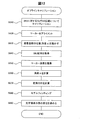
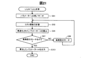
図21は、しらみつぶし計算を示すフローチャートである。初めに、0から1までを0.25毎にパラメーターtについてサーチする(S91)。次に、パラメーター設定部167は、サーチの結果を用いて、コスト関数(式(bb))を計算する(S93)。続いて、コスト関数を計算することによって、グローバルミニマムに対応するパラメーターt*を算出する(S95)。
FIG. 21 is a flowchart showing the exhaustion calculation. First, a search is performed for the parameter t from 0 to 1 every 0.25 (S91). Next, the
次に、算出したt*を、さらに高精度のサーチによってより最適化するか否かを、予め設定された指令に従い決定する(S97)。高精度のサーチを行うと決定した場合には(S97,YES)、算出したt*の近くの値に対して高精度のサーチを行い(S99)、S93以降の処理を実行する。高精度のサーチを行わないと決定した場合には(S97,NO)、算出したパラメーターt*を出力する(S101)。 Next, it is determined according to a preset command whether or not to optimize the calculated t * by a more accurate search (S97). If it is determined that a high-accuracy search is to be performed (S97, YES), a high-accuracy search is performed on values near the calculated t * (S99), and the processes after S93 are executed. If it is determined not to perform a high-accuracy search (S97, NO), the calculated parameter t * is output (S101).
上記実施形態において、ソフトウエアによって実現された機能及び処理の一部又は全部は、ハードウエアによって実現されてもよい。また、ハードウエアによって実現された機能及び処理の一部又は全部は、ソフトウエアによって実現されてもよい。ハードウエアとしては、例えば、集積回路、ディスクリート回路、または、それらの回路を組み合わせた回路モジュールなど、各種回路を用いてもよい。 In the above embodiment, some or all of the functions and processes realized by software may be realized by hardware. In addition, some or all of the functions and processes realized by hardware may be realized by software. As the hardware, for example, various circuits such as an integrated circuit, a discrete circuit, or a circuit module obtained by combining these circuits may be used.
OSTCキャリブレーションとIMU-カメラキャリブレーションとをまとめて実行することから、OSTCキャリブレーションのためのアライメントデータ収集処理において、左右の眼のそれぞれについて1回のアライメントでもよい。こうすれば、ユーザーが実行すべきアライメントの回数を減らせる。 Since the OSTC calibration and the IMU-camera calibration are performed together, the alignment data collection process for the OSTC calibration may be performed once for each of the left and right eyes. In this way, the number of alignments to be performed by the user can be reduced.
回転データ収集処理よりもアライメントデータ収集処理を先に実行してもよい。 The alignment data collection process may be executed before the rotation data collection process.
回転データ収集処理におけるキャリブレーション収集(SC217)として実行される撮像は、動画の撮像によって実現されてもよい。例えば、回転データ収集処理の実行中は、常に、カメラによって動画の撮像を継続してもよい。 Imaging performed as calibration collection (SC217) in the rotation data collection process may be realized by imaging a moving image. For example, during the execution of the rotation data collection process, the moving image may be continuously captured by the camera.
角速度ωIの導出は、IMU71の角速度の検出機能を用いて実施してもよい。例えば、頷き動作の開始時から終了時までにおける角速度を平均した値を、角速度ωIとして導出してもよい。
The derivation of the angular velocity ω I may be performed using the angular velocity detection function of the
キャリブレーション処理から、改善処理(S1000)を省略してもよい。 The improvement process (S1000) may be omitted from the calibration process.
MK1…実物マーカー、MK1A…実物マーカー、MK2…実物マーカー、OA…外部機器、10…制御部、20…画像表示部、21…右保持部、22…右表示駆動部、23…左保持部、24…左表示駆動部、26…右光学像表示部、28…左光学像表示部、40…接続部、46…連結部材、51…送信部、52…送信部、53…受信部、60…カメラ、90…装着帯、91…装着基部、92…ベルト部、93…連結部、100…頭部装着型表示装置、121…ROM、122…RAM、130…電源、135…操作部、138…マーカー画像記憶部、140…CPU、150…オペレーティングシステム、160…画像処理部、165…表示設定部、166…マーカー特定部、167…パラメーター設定部、170…音声処理部、180…インターフェース、190…表示制御部、201…右バックライト制御部、202…左バックライト制御部、211…右LCD制御部、212…左LCD制御部、221…右バックライト、241…液晶ディスプレイ、251…右投写光学系、261…右導光板、262…左導光板、300…融合部、310…測定部、311…ローパスフィルター、312…ローパスフィルター、320…予測部、330…更新部、340…重力キャンセル部、350…回転変換部、360…遅延器、900…カメラ
MK1 ... Real marker, MK1A ... Real marker, MK2 ... Real marker, OA ... External device, 10 ... Control unit, 20 ... Image display unit, 21 ... Right holding unit, 22 ... Right display driving unit, 23 ... Left holding unit, 24 ... Left display drive unit, 26 ... Right optical image display unit, 28 ... Left optical image display unit, 40 ... Connection unit, 46 ... Connection member, 51 ... Transmission unit, 52 ... Transmission unit, 53 ... Reception unit, 60 ... Camera, 90 ... wearing band, 91 ... wearing base, 92 ... belt part, 93 ... connecting part, 100 ... head-mounted display device, 121 ... ROM, 122 ... RAM, 130 ... power supply, 135 ... operation part, 138 ... Marker
Claims (5)
前記第1の実物マーカーに対する前記撮像部の相対位置が第1の位置と、第2の位置との場合において前記撮像部に前記第1の実物マーカーを撮像させて得られる撮像画像を取得する機能と、
前記第1の位置から前記第2の位置への前記慣性センサーの動きを、前記慣性センサーの出力に基づき導出する機能と、
第2の実物マーカーに対応したマーカー画像を前記画像表示部に表示する機能と、
前記マーカー画像と前記第2の実物マーカーとが一致するようにユーザーに視認される状態において、前記撮像部に前記第2の実物マーカーを撮像させて得られる撮像画像を取得する機能と、
前記撮像部および前記慣性センサーの間の第1の空間関係、並びに前記撮像部および前記画像表示部の間の第2の空間関係を、前記第1の実物マーカーの撮像画像と、前記慣性センサーの動きと、前記第2の実物マーカーの撮像画像と、に基づき導出する機能と、
を実現させるためのプログラム。 In the processing unit of the head-mounted display device including an imaging unit, an inertial sensor, an optical transmission type image display unit, and a processing unit,
A function of acquiring a captured image obtained by causing the imaging unit to image the first real marker when the relative position of the imaging unit with respect to the first real marker is the first position and the second position. When,
A function of deriving movement of the inertial sensor from the first position to the second position based on an output of the inertial sensor;
A function of displaying a marker image corresponding to the second real marker on the image display unit;
A function of acquiring a captured image obtained by causing the imaging unit to image the second real marker in a state visually recognized by the user so that the marker image and the second real marker match.
The first spatial relationship between the imaging unit and the inertial sensor, and the second spatial relationship between the imaging unit and the image display unit are expressed by the captured image of the first real marker and the inertial sensor. A function derived based on movement and a captured image of the second real marker;
A program to realize
請求項1に記載のプログラム。 The program according to claim 1, wherein a relative position of the imaging unit with respect to the inertial sensor is movable.
請求項1又は請求項2に記載のプログラム。 The program according to claim 1, wherein the imaging unit is movable in a relative position with respect to the image display unit.
前記処理部は、
前記第1の実物マーカーに対する前記撮像部の相対位置が第1の位置と、第2の位置との場合において前記撮像部に前記第1の実物マーカーを撮像させて得られる撮像画像を取得する機能と、
前記第1の位置から前記第2の位置への前記慣性センサーの動きを、前記慣性センサーの出力に基づき導出する機能と、
第2の実物マーカーに対応したマーカー画像を前記画像表示部に表示する機能と、
前記マーカー画像と前記第2の実物マーカーとが一致するようにユーザーに視認される状態において、前記撮像部に前記第2の実物マーカーを撮像させて得られる撮像画像を取得する機能と、
前記撮像部および前記慣性センサーの間の第1の空間関係、並びに前記撮像部および前記画像表示部の間の第2の空間関係を、前記第1の実物マーカーの撮像画像と、前記慣性センサーの動きと、前記第2の実物マーカーの撮像画像と、に基づき導出する機能と、を実現する
頭部装着型表示装置。 A head-mounted display device comprising an imaging unit, an inertial sensor, an optically transmissive image display unit, and a processing unit,
The processor is
A function of acquiring a captured image obtained by causing the imaging unit to image the first real marker when the relative position of the imaging unit with respect to the first real marker is the first position and the second position. When,
A function of deriving movement of the inertial sensor from the first position to the second position based on an output of the inertial sensor;
A function of displaying a marker image corresponding to the second real marker on the image display unit;
A function of acquiring a captured image obtained by causing the imaging unit to image the second real marker in a state visually recognized by the user so that the marker image and the second real marker match.
The first spatial relationship between the imaging unit and the inertial sensor, and the second spatial relationship between the imaging unit and the image display unit are expressed by the captured image of the first real marker and the inertial sensor. A head-mounted display device that realizes movement and a function derived based on a captured image of the second real marker.
第1の実物マーカーの撮像画像と、前記慣性センサーの動きと、第2の実物マーカーの撮像画像と、を取得することと、
前記撮像部および前記慣性センサーの間の第1の空間関係、並びに前記撮像部および前記画像表示部の間の第2の空間関係を、前記第1の実物マーカーの撮像画像と、前記慣性センサーの動きと、前記第2の実物マーカーの撮像画像と、に基づき導出することと、を含み、
前記第1の実物マーカーの撮像画像を取得することは、前記第1の実物マーカーに対する前記撮像部の相対位置が第1の位置と、第2の位置との場合において前記撮像部に前記第1の実物マーカーを撮像させることを含み、
前記慣性センサーの動きを取得することは、前記第1の位置から前記第2の位置への前記慣性センサーの動きを、前記慣性センサーの出力に基づき導出することを含み、
前記第2の実物マーカーの撮像画像を取得することは、
前記第2の実物マーカーに対応したマーカー画像を前記画像表示部に表示することと、
前記マーカー画像と前記第2の実物マーカーとが一致するようにユーザーに視認される状態において、前記撮像部に前記第2の実物マーカーを撮像させて得られる撮像画像を取得することと、を含む
キャリブレーション方法。 A calibration method executed by the processing unit of a head-mounted display device including an imaging unit, an inertial sensor, an optically transmissive image display unit, and a processing unit,
Obtaining a captured image of a first real marker, a movement of the inertial sensor, and a captured image of a second real marker;
The first spatial relationship between the imaging unit and the inertial sensor, and the second spatial relationship between the imaging unit and the image display unit are expressed by the captured image of the first real marker and the inertial sensor. Deriving based on movement and a captured image of the second real marker,
Acquiring a captured image of the first real marker means that the first image is captured by the image capturing unit when the relative position of the image capturing unit with respect to the first real marker is a first position and a second position. Including imaging a real marker of
Obtaining the motion of the inertial sensor includes deriving a motion of the inertial sensor from the first position to the second position based on an output of the inertial sensor;
Acquiring a captured image of the second real marker is
Displaying a marker image corresponding to the second real marker on the image display unit;
Including acquiring a captured image obtained by causing the imaging unit to capture the second real marker in a state where the user visually recognizes the marker image and the second real marker to coincide with each other. Calibration method.
Priority Applications (2)
| Application Number | Priority Date | Filing Date | Title |
|---|---|---|---|
| JP2016137529A JP2018009836A (en) | 2016-07-12 | 2016-07-12 | Program, head-mounted display device, calibration method |
| US15/641,677 US10269139B2 (en) | 2016-07-12 | 2017-07-05 | Computer program, head-mounted display device, and calibration method |
Applications Claiming Priority (1)
| Application Number | Priority Date | Filing Date | Title |
|---|---|---|---|
| JP2016137529A JP2018009836A (en) | 2016-07-12 | 2016-07-12 | Program, head-mounted display device, calibration method |
Publications (1)
| Publication Number | Publication Date |
|---|---|
| JP2018009836A true JP2018009836A (en) | 2018-01-18 |
Family
ID=60941729
Family Applications (1)
| Application Number | Title | Priority Date | Filing Date |
|---|---|---|---|
| JP2016137529A Pending JP2018009836A (en) | 2016-07-12 | 2016-07-12 | Program, head-mounted display device, calibration method |
Country Status (2)
| Country | Link |
|---|---|
| US (1) | US10269139B2 (en) |
| JP (1) | JP2018009836A (en) |
Cited By (4)
| Publication number | Priority date | Publication date | Assignee | Title |
|---|---|---|---|---|
| JP2020204552A (en) * | 2019-06-18 | 2020-12-24 | 株式会社ミツトヨ | measuring device |
| JP2022515968A (en) * | 2018-12-27 | 2022-02-24 | フェイスブック・テクノロジーズ・リミテッド・ライアビリティ・カンパニー | Head-mounted display calibration using a portable docking station with a calibration target |
| JP2023086528A (en) * | 2021-12-10 | 2023-06-22 | 株式会社ブリヂストン | Shift amount control system, shift amount control method, and program |
| WO2026018351A1 (en) * | 2024-07-17 | 2026-01-22 | Eizo株式会社 | Image correction device, image correction method, and image correction program |
Families Citing this family (26)
| Publication number | Priority date | Publication date | Assignee | Title |
|---|---|---|---|---|
| GB2536650A (en) | 2015-03-24 | 2016-09-28 | Augmedics Ltd | Method and system for combining video-based and optic-based augmented reality in a near eye display |
| US10241587B2 (en) * | 2016-12-22 | 2019-03-26 | Microsoft Technology Licensing, Llc | Magnetic tracker power duty cycling |
| US12458411B2 (en) | 2017-12-07 | 2025-11-04 | Augmedics Ltd. | Spinous process clamp |
| EP3787543A4 (en) | 2018-05-02 | 2022-01-19 | Augmedics Ltd. | Registration of a fiducial marker for an augmented reality system |
| US11766296B2 (en) | 2018-11-26 | 2023-09-26 | Augmedics Ltd. | Tracking system for image-guided surgery |
| US10939977B2 (en) | 2018-11-26 | 2021-03-09 | Augmedics Ltd. | Positioning marker |
| WO2020114582A1 (en) | 2018-12-04 | 2020-06-11 | Telefonaktiebolaget Lm Ericsson (Publ) | Improved optical see-through viewing device and method for providing virtual content overlapping visual objects |
| WO2020244780A1 (en) | 2019-06-07 | 2020-12-10 | Telefonaktiebolaget Lm Ericsson (Publ) | Improved optical see-through viewing device and method for calibrating provision of virtual content overlapping visual objects |
| EP3760157A1 (en) | 2019-07-04 | 2021-01-06 | Scopis GmbH | Technique for calibrating a registration of an augmented reality device |
| US12178666B2 (en) | 2019-07-29 | 2024-12-31 | Augmedics Ltd. | Fiducial marker |
| US11980506B2 (en) | 2019-07-29 | 2024-05-14 | Augmedics Ltd. | Fiducial marker |
| JP7404011B2 (en) * | 2019-09-24 | 2023-12-25 | 東芝テック株式会社 | information processing equipment |
| US11443455B2 (en) * | 2019-10-24 | 2022-09-13 | Microsoft Technology Licensing, Llc | Prior informed pose and scale estimation |
| US11382712B2 (en) * | 2019-12-22 | 2022-07-12 | Augmedics Ltd. | Mirroring in image guided surgery |
| US11389252B2 (en) | 2020-06-15 | 2022-07-19 | Augmedics Ltd. | Rotating marker for image guided surgery |
| US12502163B2 (en) | 2020-09-09 | 2025-12-23 | Augmedics Ltd. | Universal tool adapter for image-guided surgery |
| US12239385B2 (en) | 2020-09-09 | 2025-03-04 | Augmedics Ltd. | Universal tool adapter |
| KR102932214B1 (en) * | 2020-12-30 | 2026-03-03 | 스냅 인코포레이티드 | Periodic parameter estimation visual inertial tracking system |
| US12150821B2 (en) | 2021-07-29 | 2024-11-26 | Augmedics Ltd. | Rotating marker and adapter for image-guided surgery |
| US12475662B2 (en) | 2021-08-18 | 2025-11-18 | Augmedics Ltd. | Stereoscopic display and digital loupe for augmented-reality near-eye display |
| WO2023048985A1 (en) * | 2021-09-22 | 2023-03-30 | Callisto Design Solutions Llc | Fit guidance |
| US11863730B2 (en) * | 2021-12-07 | 2024-01-02 | Snap Inc. | Optical waveguide combiner systems and methods |
| WO2023203521A1 (en) | 2022-04-21 | 2023-10-26 | Augmedics Ltd. | Systems and methods for medical image visualization |
| JP2025531829A (en) | 2022-09-13 | 2025-09-25 | オーグメディックス リミテッド | Augmented reality eyewear for image-guided medical interventions |
| US20240312145A1 (en) * | 2023-03-15 | 2024-09-19 | Snap Inc. | Tight imu-camera coupling for dynamic bending estimation |
| CN116183169B (en) * | 2023-05-04 | 2023-08-01 | 武汉精立电子技术有限公司 | Center alignment method, device and equipment for displaying product image and storage medium |
Family Cites Families (4)
| Publication number | Priority date | Publication date | Assignee | Title |
|---|---|---|---|---|
| JP2005038321A (en) | 2003-07-18 | 2005-02-10 | Canon Inc | Head mounted display device |
| US8810649B2 (en) * | 2011-06-30 | 2014-08-19 | Qualcomm Incorporated | Navigation in buildings with rectangular floor plan |
| US10444845B2 (en) | 2012-12-21 | 2019-10-15 | Qualcomm Incorporated | Display of separate computer vision based pose and inertial sensor based pose |
| US10070120B2 (en) * | 2014-09-17 | 2018-09-04 | Qualcomm Incorporated | Optical see-through display calibration |
-
2016
- 2016-07-12 JP JP2016137529A patent/JP2018009836A/en active Pending
-
2017
- 2017-07-05 US US15/641,677 patent/US10269139B2/en active Active
Cited By (6)
| Publication number | Priority date | Publication date | Assignee | Title |
|---|---|---|---|---|
| JP2022515968A (en) * | 2018-12-27 | 2022-02-24 | フェイスブック・テクノロジーズ・リミテッド・ライアビリティ・カンパニー | Head-mounted display calibration using a portable docking station with a calibration target |
| JP2020204552A (en) * | 2019-06-18 | 2020-12-24 | 株式会社ミツトヨ | measuring device |
| JP7408303B2 (en) | 2019-06-18 | 2024-01-05 | 株式会社ミツトヨ | measuring device |
| JP2023086528A (en) * | 2021-12-10 | 2023-06-22 | 株式会社ブリヂストン | Shift amount control system, shift amount control method, and program |
| JP7696285B2 (en) | 2021-12-10 | 2025-06-20 | 株式会社ブリヂストン | SHIFT AMOUNT CONTROL SYSTEM, SHIFT AMOUNT CONTROL METHOD, AND PROGRAM |
| WO2026018351A1 (en) * | 2024-07-17 | 2026-01-22 | Eizo株式会社 | Image correction device, image correction method, and image correction program |
Also Published As
| Publication number | Publication date |
|---|---|
| US20180018791A1 (en) | 2018-01-18 |
| US10269139B2 (en) | 2019-04-23 |
Similar Documents
| Publication | Publication Date | Title |
|---|---|---|
| JP2018009836A (en) | Program, head-mounted display device, calibration method | |
| CN114761909B (en) | Head mounted device and method for adjusting rendering of virtual content items | |
| US10242504B2 (en) | Head-mounted display device and computer program | |
| CN107408314B (en) | Mixed reality system | |
| CN109146965B (en) | Information processing apparatus, computer readable medium, and head-mounted display apparatus | |
| US9401050B2 (en) | Recalibration of a flexible mixed reality device | |
| JP6852355B2 (en) | Program, head-mounted display device | |
| JP6565465B2 (en) | Image display device, computer program, and image display system | |
| US10365710B2 (en) | Head-mounted display device configured to display a visual element at a location derived from sensor data and perform calibration | |
| US10469836B2 (en) | Head-mounted display device and computer program | |
| CN110047104A (en) | Object detection and tracking, head-mounted display apparatus and storage medium | |
| JP2018067115A (en) | Program, tracking method, tracking device | |
| JP2017224984A (en) | Program, device, and calibration method | |
| US10992928B1 (en) | Calibration system for concurrent calibration of device sensors | |
| JP2018055589A (en) | Program, object tracking method, display device | |
| JP6701694B2 (en) | Head-mounted display and computer program | |
| JP6890524B2 (en) | Attitude control system | |
| JP6701693B2 (en) | Head-mounted display and computer program | |
| US12238495B2 (en) | Eyewear with audio source separation using pose trackers | |
| JP2021122079A (en) | Information processing device, information processing method, and program |