JP2018004431A - List apparatus - Google Patents
List apparatus Download PDFInfo
- Publication number
- JP2018004431A JP2018004431A JP2016131381A JP2016131381A JP2018004431A JP 2018004431 A JP2018004431 A JP 2018004431A JP 2016131381 A JP2016131381 A JP 2016131381A JP 2016131381 A JP2016131381 A JP 2016131381A JP 2018004431 A JP2018004431 A JP 2018004431A
- Authority
- JP
- Japan
- Prior art keywords
- sensor
- information
- display
- unit
- wrist device
- Prior art date
- Legal status (The legal status is an assumption and is not a legal conclusion. Google has not performed a legal analysis and makes no representation as to the accuracy of the status listed.)
- Withdrawn
Links
Images


Classifications
-
- G—PHYSICS
- G04—HOROLOGY
- G04G—ELECTRONIC TIME-PIECES
- G04G21/00—Input or output devices integrated in time-pieces
- G04G21/02—Detectors of external physical values, e.g. temperature
-
- G—PHYSICS
- G01—MEASURING; TESTING
- G01S—RADIO DIRECTION-FINDING; RADIO NAVIGATION; DETERMINING DISTANCE OR VELOCITY BY USE OF RADIO WAVES; LOCATING OR PRESENCE-DETECTING BY USE OF THE REFLECTION OR RERADIATION OF RADIO WAVES; ANALOGOUS ARRANGEMENTS USING OTHER WAVES
- G01S19/00—Satellite radio beacon positioning systems; Determining position, velocity or attitude using signals transmitted by such systems
- G01S19/01—Satellite radio beacon positioning systems transmitting time-stamped messages, e.g. GPS [Global Positioning System], GLONASS [Global Orbiting Navigation Satellite System] or GALILEO
- G01S19/13—Receivers
- G01S19/14—Receivers specially adapted for specific applications
-
- G—PHYSICS
- G04—HOROLOGY
- G04R—RADIO-CONTROLLED TIME-PIECES
- G04R20/00—Setting the time according to the time information carried or implied by the radio signal
- G04R20/02—Setting the time according to the time information carried or implied by the radio signal the radio signal being sent by a satellite, e.g. GPS
-
- G—PHYSICS
- G06—COMPUTING; CALCULATING OR COUNTING
- G06F—ELECTRIC DIGITAL DATA PROCESSING
- G06F1/00—Details not covered by groups G06F3/00 - G06F13/00 and G06F21/00
- G06F1/16—Constructional details or arrangements
- G06F1/1613—Constructional details or arrangements for portable computers
- G06F1/163—Wearable computers, e.g. on a belt
-
- G—PHYSICS
- G06—COMPUTING; CALCULATING OR COUNTING
- G06F—ELECTRIC DIGITAL DATA PROCESSING
- G06F1/00—Details not covered by groups G06F3/00 - G06F13/00 and G06F21/00
- G06F1/16—Constructional details or arrangements
- G06F1/1613—Constructional details or arrangements for portable computers
- G06F1/1633—Constructional details or arrangements of portable computers not specific to the type of enclosures covered by groups G06F1/1615 - G06F1/1626
- G06F1/1656—Details related to functional adaptations of the enclosure, e.g. to provide protection against EMI, shock, water, or to host detachable peripherals like a mouse or removable expansions units like PCMCIA cards, or to provide access to internal components for maintenance or to removable storage supports like CDs or DVDs, or to mechanically mount accessories
- G06F1/1658—Details related to functional adaptations of the enclosure, e.g. to provide protection against EMI, shock, water, or to host detachable peripherals like a mouse or removable expansions units like PCMCIA cards, or to provide access to internal components for maintenance or to removable storage supports like CDs or DVDs, or to mechanically mount accessories related to the mounting of internal components, e.g. disc drive or any other functional module
-
- G—PHYSICS
- G06—COMPUTING; CALCULATING OR COUNTING
- G06F—ELECTRIC DIGITAL DATA PROCESSING
- G06F1/00—Details not covered by groups G06F3/00 - G06F13/00 and G06F21/00
- G06F1/16—Constructional details or arrangements
- G06F1/1613—Constructional details or arrangements for portable computers
- G06F1/1633—Constructional details or arrangements of portable computers not specific to the type of enclosures covered by groups G06F1/1615 - G06F1/1626
- G06F1/1684—Constructional details or arrangements related to integrated I/O peripherals not covered by groups G06F1/1635 - G06F1/1675
- G06F1/1694—Constructional details or arrangements related to integrated I/O peripherals not covered by groups G06F1/1635 - G06F1/1675 the I/O peripheral being a single or a set of motion sensors for pointer control or gesture input obtained by sensing movements of the portable computer
-
- G—PHYSICS
- G01—MEASURING; TESTING
- G01S—RADIO DIRECTION-FINDING; RADIO NAVIGATION; DETERMINING DISTANCE OR VELOCITY BY USE OF RADIO WAVES; LOCATING OR PRESENCE-DETECTING BY USE OF THE REFLECTION OR RERADIATION OF RADIO WAVES; ANALOGOUS ARRANGEMENTS USING OTHER WAVES
- G01S19/00—Satellite radio beacon positioning systems; Determining position, velocity or attitude using signals transmitted by such systems
- G01S19/01—Satellite radio beacon positioning systems transmitting time-stamped messages, e.g. GPS [Global Positioning System], GLONASS [Global Orbiting Navigation Satellite System] or GALILEO
- G01S19/13—Receivers
- G01S19/34—Power consumption
-
- G—PHYSICS
- G04—HOROLOGY
- G04C—ELECTROMECHANICAL CLOCKS OR WATCHES
- G04C10/00—Arrangements of electric power supplies in time pieces
- G04C10/04—Arrangements of electric power supplies in time pieces with means for indicating the condition of the power supply
-
- G—PHYSICS
- G04—HOROLOGY
- G04G—ELECTRONIC TIME-PIECES
- G04G17/00—Structural details; Housings
- G04G17/08—Housings
-
- G—PHYSICS
- G04—HOROLOGY
- G04G—ELECTRONIC TIME-PIECES
- G04G21/00—Input or output devices integrated in time-pieces
-
- G—PHYSICS
- G04—HOROLOGY
- G04G—ELECTRONIC TIME-PIECES
- G04G9/00—Visual time or date indication means
- G04G9/0064—Visual time or date indication means in which functions not related to time can be displayed
-
- H—ELECTRICITY
- H04—ELECTRIC COMMUNICATION TECHNIQUE
- H04M—TELEPHONIC COMMUNICATION
- H04M2250/00—Details of telephonic subscriber devices
- H04M2250/12—Details of telephonic subscriber devices including a sensor for measuring a physical value, e.g. temperature or motion
Abstract
Description
本発明は、センシングデバイスを備えたリスト機器に関する。 The present invention relates to a wrist device including a sensing device.
近年、例えば方位、高度(気圧)などを検知する各種センシングデバイスが搭載され、時刻と、該センシングデバイスによって取得された種々の情報をユーザーに提供するリスト機器が提示されている。例えば特許文献1には、センシングデバイスとして圧力センサーおよび電子方位センサーを備え、該圧力センサーおよび電子方位センサーによって検知された種々の情報を、本体ケースおよびリストバンドに備えられた表示部にデジタル表示される構成の携帯機器(リスト機器)が開示されている。なお、このような携帯機器(リスト機器)では、表示バリエーションを多く提示できることから、デジタル表示が主流とされている。
In recent years, for example, various sensing devices that detect azimuth, altitude (atmospheric pressure), and the like are mounted, and list devices that provide time and various information acquired by the sensing device to users have been presented. For example,
上述のように各種センシングデバイスが搭載された携帯機器(リスト機器)では、特許文献1に記載されているように、デジタル表示される構成が主流である。しかしながら、種々の情報を限られたサイズの表示部にデジタル表示で提示すると、文字が小さくなったり複雑な画像を描画しきれなかったりすることなどによって情報の判読が行い難く、それらに対応するために表示部が大型になり、ファッション性が劣ってしまうなどの課題を有していた。また、種々のセンシングデバイスを駆動するために電池使用量が多くなり、内蔵されている電池寿命を考慮して、使用可能なセンシングデバイスを制限するなど、ユーザーの期待に副えないなどの課題も有していた。
As described above, in a portable device (list device) in which various sensing devices are mounted as described above, a digital display configuration is mainstream as described in
本発明は、上述の課題の少なくとも一部を解決するためになされたものであり、以下の形態または適用例として実現することが可能である。 SUMMARY An advantage of some aspects of the invention is to solve at least a part of the problems described above, and the invention can be implemented as the following forms or application examples.
[適用例1]本適用例に係るリスト機器は、位置情報衛星から送信される衛星信号を受信する受信部と、複数のセンサーと、自己発電機能を備えた電源部と、指示針を用いて情報を表示する表示部と、を備えていることを特徴とする。 Application Example 1 A wrist device according to this application example uses a receiving unit that receives a satellite signal transmitted from a position information satellite, a plurality of sensors, a power supply unit that has a self-power generation function, and an indicator needle. And a display unit for displaying information.
本適用例のリスト機器によれば、情報が指示針によって表示されるため、表示の視認性が高まり、比較的小型の表示部内に表示させることが可能となる。これにより、リスト機器を装着しても、通常の腕時計と同様な装着が可能となり、装着性を高めることが可能となるとともに、機器のファッション性を向上させることが可能となる。
また、電源部に自己発電機能が備えられているため、電源部への電力供給を自己発電によって賄うことができ、比較的消費電力の大きなGPSなどの機能や複数のセンサーなどを搭載することができる。
これらにより、ユーザーが一般生活において欲する情報である、例えばGPS(Global Positioning System)による位置情報などを含む情報を得ることが可能なリスト機器を提供することができる。
According to the wrist device of this application example, since the information is displayed by the pointing hand, the visibility of the display is improved, and the information can be displayed in a relatively small display unit. As a result, even if the wrist device is mounted, it is possible to mount the wrist device in the same manner as a normal wristwatch, and it is possible to improve the wearability and improve the fashionability of the device.
In addition, since the power supply unit is equipped with a self-power generation function, power supply to the power supply unit can be provided by self-power generation, and functions such as GPS with relatively large power consumption and multiple sensors can be installed. it can.
Thus, it is possible to provide a list device that can obtain information that the user desires in general life, for example, information including position information by GPS (Global Positioning System).
[適用例2]上記適用例に記載のリスト機器において、前記センサーは、物理量を検知する、加速度センサー、圧力センサー、および方位センサーのいずれかを含むことが好ましい。 Application Example 2 In the wrist device described in the application example, it is preferable that the sensor includes any one of an acceleration sensor, a pressure sensor, and a direction sensor that detect a physical quantity.
本適用例によれば、例えばGPS(Global Positioning System)による位置情報に加えて、ユーザーの欲する情報として、例えば加速度センサー、圧力センサー、および方位センサーによる検知結果に基づく、ユーザー(装着者)の移動方向や標高差を含む移動量(運動量)などの情報を容易に得ることができる。 According to this application example, in addition to position information based on, for example, GPS (Global Positioning System), information desired by the user, for example, movement of the user (wearer) based on detection results from an acceleration sensor, a pressure sensor, and a direction sensor. Information such as the amount of movement (momentum) including the direction and elevation difference can be easily obtained.
[適用例3]上記適用例に記載のリスト機器において、前記センサーは、物理量を検知する、照度センサー、温度センサー、および湿度センサーのいずれかを含むことが好ましい。 Application Example 3 In the wrist device described in the application example, it is preferable that the sensor includes any one of an illuminance sensor, a temperature sensor, and a humidity sensor that detect a physical quantity.
本適用例によれば、例えば天候が現在からどのように変化していくのかなどの天候予測に係る情報を容易に得ることができる。 According to this application example, it is possible to easily obtain information related to weather prediction such as how the weather changes from the present time.
[適用例4]上記適用例に記載のリスト機器において、前記センサーは、生体情報を検知する、脈波計測センサー、脈拍計測センサー、血圧計測センサー、体温センサー、電気皮膚反応センサーのいずれかを含む生体情報検知センサーであることが好ましい。 Application Example 4 In the wrist device according to the application example described above, the sensor includes any one of a pulse wave measurement sensor, a pulse measurement sensor, a blood pressure measurement sensor, a body temperature sensor, and an electric skin reaction sensor that detects biological information. A biological information detection sensor is preferred.
本適用例によれば、位置情報や物理量の情報に加えて、ユーザー(装着者)の、例えば、脈拍、血圧値、血糖値などの生体情報を容易に得ることができる。これにより、ユーザーは、ライフログとして、健康情報や身体情報を得ることができる。 According to this application example, in addition to position information and physical quantity information, it is possible to easily obtain biological information such as a pulse, a blood pressure value, and a blood glucose level of the user (wearer). Thereby, the user can obtain health information and physical information as a life log.
[適用例5]上記適用例に記載のリスト機器において、少なくとも前記受信部を収容するケースと、前記ケースの裏側に配置された裏蓋部と、を備え、前記生体情報検知センサーは、前記裏蓋部に配置されていることが好ましい。 Application Example 5 In the wrist device according to the application example described above, the wrist device includes at least a case that houses the receiving unit, and a back cover unit that is disposed on the back side of the case, and the biological information detection sensor includes the back device. It is preferable that it is arrange | positioned at a cover part.
本適用例によれば、生体情報検知センサーが裏蓋部に配置されていることから、生体情報検知センサーをユーザー(装着者)の装着部(腕部)に密着させることができ、生体情報をより正確に検知することができる。 According to this application example, since the biological information detection sensor is arranged on the back cover part, the biological information detection sensor can be brought into close contact with the wearing part (arm part) of the user (wearer), It can be detected more accurately.
[適用例6]上記適用例に記載のリスト機器において、少なくとも前記受信部を収容するケースと、前記ケースに接続されたバンド部と、を備え、前記生体情報検知センサーは、前記バンド部に配置されていることが好ましい。 Application Example 6 In the wrist device according to the application example described above, the wrist device includes at least a case housing the receiving unit and a band unit connected to the case, and the biological information detection sensor is disposed in the band unit. It is preferable that
本適用例によれば、生体情報検知センサーがバンド部に配置されていることから、生体情報検知センサーの脱着を容易に行うことができる。これにより、ユーザーの所望に応じてセンサーの種類を変更するなど、容易にカスタマイズすることができる。 According to this application example, since the biological information detection sensor is disposed in the band portion, the biological information detection sensor can be easily attached and detached. Thereby, it is possible to easily customize such as changing the type of sensor according to the user's desire.
[適用例7]上記適用例に記載のリスト機器において、前記生体情報から、SpO2(経皮的動脈血酸素飽和度)、VO2max(最大酸素摂取量)、体温、乳酸値、SvO2(ヘモグロビンの酸素飽和度)、睡眠状態、ストレス、血糖値、不整脈、カロリー消費量、代謝、および排卵の少なくとも一つを表す指標を求めることが好ましい。 Application Example 7 In the wrist device described in the application example above, SpO 2 (percutaneous arterial blood oxygen saturation), VO 2max (maximum oxygen uptake), body temperature, lactate value, SvO 2 (hemoglobin) from the biological information. (Oxygen saturation), sleep state, stress, blood sugar level, arrhythmia, calorie consumption, metabolism, and ovulation are preferably determined.
本適用例によれば、前記生体情報からユーザー(装着者)の身体状態や精神状態を容易に求めることができ、ユーザーはそれらの情報を容易に把握することができる。 According to this application example, the physical state and mental state of the user (wearer) can be easily obtained from the biological information, and the user can easily grasp the information.
[適用例8]上記適用例に記載のリスト機器において、前記電源部は、太陽電池によって電気エネルギーを取得する発電機能、および回転錘の運動エネルギーを変換して電気エネルギーを取得する発電機能の少なくとも一方を有していることが好ましい。 Application Example 8 In the wrist device according to the application example described above, the power supply unit includes at least a power generation function that acquires electrical energy by a solar cell and a power generation function that acquires electrical energy by converting kinetic energy of a rotating weight. It is preferable to have one.
本適用例によれば、電源部において、ユーザーの入手が容易な自然エネルギーである太陽光を用いたり、ユーザー(装着者)の腕の動きを用いたりして発電するため、環境に影響を生じない所謂クリーンエネルギーを動力源(電源)とすることができる。 According to this application example, the power generation unit generates power by using sunlight, which is natural energy that is easily available to the user, or by using the movement of the user's (wearer's) arm. No so-called clean energy can be used as a power source (power source).
[適用例9]上記適用例に記載のリスト機器において、他の電子機器との間において、信号を送受信する通信部を備え、前記通信部は、無線通信または有線通信により信号の送受信を行うことが好ましい。 Application Example 9 The wrist device described in the application example includes a communication unit that transmits and receives signals to and from other electronic devices, and the communication unit transmits and receives signals by wireless communication or wired communication. Is preferred.
本適用例によれば、位置情報や複数のセンサーによって検知された情報を、例えばパーソナルコンピューター(PC)やモバイル機器などの電子機器に送信して確認することができる。リスト機器は、携帯性から比較的小さな表示部となってしまうが、それと比較するとこれらの電子機器は、大型の表示部を用いているため、必要な情報を見やすく表示することができる。また、ユーザーと他のユーザーとの間での情報のやり取りを行なうことができる。 According to this application example, position information and information detected by a plurality of sensors can be transmitted to an electronic device such as a personal computer (PC) or a mobile device for confirmation. The wrist device is a relatively small display unit due to its portability. However, in comparison with this, these electronic devices use a large display unit, so that necessary information can be easily displayed. In addition, information can be exchanged between the user and other users.
[適用例10]上記適用例に記載のリスト機器において、前記指示針は、前記指示針と接続された回転軸、および前記回転軸を回転させる駆動部によって回動されることが好ましい。 Application Example 10 In the wrist device according to the application example described above, it is preferable that the indicating needle is rotated by a rotating shaft connected to the indicating needle and a drive unit that rotates the rotating shaft.
本適用例によれば、情報を回動可能な指示針によってアナログ表示することから、小型の表示部を構成することが可能となり、機器全体を小型にできファッション性を高めることができるとともに、装着感を向上させることができる。 According to this application example, since information is displayed in an analog manner by a rotatable indicator needle, a small display unit can be configured, and the entire device can be reduced in size and fashionability can be improved. A feeling can be improved.
[適用例11]上記適用例に記載のリスト機器において、前記表示部は、デジタル表示によって表示されるデジタル表示部を備えていることが好ましい。 Application Example 11 In the wrist device described in the application example, it is preferable that the display unit includes a digital display unit displayed by digital display.
本適用例によれば、表示部に備えられたデジタル表示部に指示針をデジタル表示させることで、デザインや表示情報を容易に変更することが可能となる。 According to this application example, the design and display information can be easily changed by digitally displaying the pointer on the digital display unit provided in the display unit.
[適用例12]上記適用例に記載のリスト機器において、前記デジタル表示部は、電気泳動ディスプレイモジュール、有機エレクトロルミネッセンスディスプレイ、および液晶ディスプレイの少なくとも一つを用いていることが好ましい。 Application Example 12 In the wrist device described in the application example, it is preferable that the digital display unit uses at least one of an electrophoretic display module, an organic electroluminescence display, and a liquid crystal display.
本適用例によれば、容易にデジタル表示を行なうことができる。なお、電気泳動ディスプレイモジュール(EPD)を用いれば、消費電力が抑えられるとともに、明るいところでの視認性がよい。また、有機エレクトロルミネッセンス(OLED)を用いたディスプレイによれば、発色が良く、且つ輝度を高くすることができる。また、液晶(LCD)を用いたディスプレイによれば、安価であり、且つ温度変化に対する影響を小さくすることができる。 According to this application example, digital display can be easily performed. Note that when an electrophoretic display module (EPD) is used, power consumption is suppressed and visibility in a bright place is good. In addition, according to a display using organic electroluminescence (OLED), coloring is good and the luminance can be increased. In addition, a display using a liquid crystal (LCD) is inexpensive and can reduce the influence on temperature change.
[適用例13]上記適用例に記載のリスト機器において、前記表示部は、小窓部を備えていることが好ましい。 Application Example 13 In the wrist device described in the application example, it is preferable that the display unit includes a small window part.
本適用例によれば、複数のセンサーによって検知されたそれぞれの情報を、それぞれ異なる小窓部に表示することができる。これにより、検知された情報を分かり易く表示することができる。 According to this application example, each piece of information detected by a plurality of sensors can be displayed in different small window portions. Thereby, the detected information can be displayed in an easy-to-understand manner.
[適用例14]上記適用例に記載のリスト機器において、前記小窓部は、1個以上4個以下の数で設けられていることが好ましい。 Application Example 14 In the wrist device described in the application example, it is preferable that the small window portions are provided in a number of 1 to 4 in number.
本適用例によれば、小窓部の数を1個以上4個以下とすることにより、小窓部を視認性のよい適度な大きさに設定することができる。換言すれば、小窓部を5個以上とすると、表示部の限られたスペースの中では、それぞれの小窓部が小さくなってしまい、表示されている情報の視認性が低下し、一見での視認が困難となる。 According to this application example, by setting the number of small window portions to 1 or more and 4 or less, the small window portions can be set to an appropriate size with good visibility. In other words, if the number of small window portions is five or more, each small window portion becomes small in a limited space of the display portion, and the visibility of the displayed information is reduced. Is difficult to see.
[適用例15]上記適用例に記載のリスト機器において、前記複数のセンサーのそれぞれに対応した動作を行う動作モードを複数有し、前記小窓部の少なくとも一つは、前記動作モードそれぞれに対応したモード表示部が設けられていることが好ましい。 [Application Example 15] The wrist device according to the application example described above includes a plurality of operation modes for performing operations corresponding to each of the plurality of sensors, and at least one of the small windows corresponds to each of the operation modes. It is preferable that a mode display unit is provided.
本適用例によれば、複数のセンサーによって検知された複数の情報の内のいずれの動作モードの情報が表示されているかを容易に識別することができる。 According to this application example, it is possible to easily identify which operation mode information of a plurality of pieces of information detected by a plurality of sensors is displayed.
[適用例16]上記適用例に記載のリスト機器において、前記ケースは、金属で構成されていることが好ましい。 [Application Example 16] In the wrist device described in the application example, it is preferable that the case is made of metal.
本適用例によれば、ケースに収容されているセンサーの検知結果に影響するケースの外部からの外乱ノイズを遮蔽することができる。また、高級感を感じさせたりファッション性を高めたりすることができる。 According to this application example, it is possible to shield disturbance noise from the outside of the case that affects the detection result of the sensor accommodated in the case. Moreover, it can give a sense of luxury and enhance fashionability.
[適用例17]上記適用例に記載のリスト機器において、前記受信部に備えられているアンテナは、リングアンテナ、およびパッチアンテナの少なくとも一方であることが好ましい。 Application Example 17 In the wrist device described in the application example, it is preferable that the antenna provided in the receiving unit is at least one of a ring antenna and a patch antenna.
本適用例によれば、小型機器に容易に定容(収容)することができる。例えば、リングアンテナを用いれば、受信感度を向上させることができ、パッチアンテナを用いれば、センサーの配置レイアウトなど機器の設計自由度を高めることができる。 According to this application example, it can be easily fixed (accommodated) in a small device. For example, if a ring antenna is used, the reception sensitivity can be improved, and if a patch antenna is used, the degree of freedom in device design such as sensor layout can be increased.
[適用例18]上記適用例に記載のリスト機器において、クロノグラフ機能、およびデュアルタイム機能の少なくとも一方を備えていることが好ましい。 [Application Example 18] The wrist device described in the application example described above preferably includes at least one of a chronograph function and a dual time function.
本適用例によれば、さらに、ユーザーの欲する種々の時計(計時)情報を提供することが可能となる。 According to this application example, it is possible to provide various clock (timekeeping) information desired by the user.
[適用例19]上記適用例に記載のリスト機器において、前記情報は、アナログとデジタルとを併用して表示されることが好ましい。 Application Example 19 In the wrist device described in the application example, it is preferable that the information is displayed using both analog and digital.
本適用例によれば、アナログによる表示とデジタルによる表示とを併用することにより、提示できる情報の種類や情報量を増やすことができる。 According to this application example, the combination of analog display and digital display can increase the types of information and the amount of information that can be presented.
[適用例20]上記適用例に記載のリスト機器において、前記衛星信号に含まれる時刻情報を取得して現在時刻を補正する時刻補正部を備えていることが好ましい。 Application Example 20 The wrist device described in the application example described above preferably includes a time correction unit that acquires time information included in the satellite signal and corrects the current time.
本適用例によれば、衛星信号に含まれる時刻情報を取得して現在時刻を補正する時刻補正部によって補正された時刻情報を得ることができる。 According to this application example, it is possible to obtain the time information corrected by the time correction unit that acquires the time information included in the satellite signal and corrects the current time.
[適用例21]上記適用例に記載のリスト機器において、前記時刻表示部は、前記衛星信号と異なる周波数の電波を受信する第2受信部を備え、前記時刻補正部は、前記受信部または前記第2受信部による受信の結果に基づいて、時刻の補正を行うことが好ましい。 Application Example 21 In the wrist device according to the application example described above, the time display unit includes a second reception unit that receives radio waves having a frequency different from that of the satellite signal, and the time correction unit includes the reception unit or the It is preferable to correct the time based on the result of reception by the second receiver.
本適用例によれば、例えば電波の受信できない場所にいる場合などで、いずれか一方の電波を受信することができなくても、他方の電波を適用して時刻の補正を行うことにより、常に正確な計時を継続して表示することができる。 According to this application example, even when one of the radio waves cannot be received, for example, in a place where radio waves cannot be received, the time correction is always performed by applying the other radio wave. Accurate timing can be continuously displayed.
[適用例22]上記適用例に記載のリスト機器において、他のセンサー機器と接続され、前記他のセンサー機器の検知した第2物理情報を、前記指示針を用いて前記表示部に表示することが好ましい。 Application Example 22 In the wrist device described in the application example, the second physical information detected by the other sensor device connected to another sensor device is displayed on the display unit using the indicator needle. Is preferred.
本適用例によれば、当該リスト機器では検知できない情報、例えば第2物理情報などを、他のセンサー機器によって検知し、その情報を当該リスト機器の表示部に指示針を用いて表示することが可能となるなど、使い勝手を向上させることができる。 According to this application example, information that cannot be detected by the list device, such as second physical information, is detected by another sensor device, and the information is displayed on the display unit of the list device using an indicator needle. Usability can be improved, for example.
以下、図面を参照しながら本発明に係る実施の形態を説明する。なお、図面において各部の寸法や縮尺は実際のものと適宜異なる。また、以下に記載する実施の形態は、本発明の好適な具体例であるから技術的に好ましい種々の限定が付されているが、本発明の範囲は、以下の説明において特に本発明を限定する旨の記載がない限り、これらの形態に限られるものではない。 Hereinafter, embodiments of the present invention will be described with reference to the drawings. In the drawings, the size and scale of each part are appropriately different from the actual ones. Further, since the embodiments described below are preferred specific examples of the present invention, various technically preferable limitations are attached thereto. However, the scope of the present invention is particularly limited in the following description. Unless otherwise stated, the present invention is not limited to these forms.
<第1実施形態>
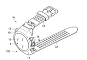
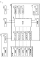
図1A、図1B、図2、および図3を参照して、本発明のリスト機器の第1実施形態に係るセンサー付き電子時計について説明する。図1Aは、本発明のリスト機器の第1実施形態に係るセンサー付き電子時計を含むGPS(Global Positioning System)の全体図である。図1Bは、第1実施形態に係るセンサー付き電子時計の概略を示す斜視図である。図2は、第1実施形態に係るセンサー付き電子時計の構成を示す機能ブロック図である。図3は、第1実施形態に係るセンサー付き電子時計の標高計測モードの表示部を示す平面図である。
<First Embodiment>
With reference to FIG. 1A, FIG. 1B, FIG. 2, and FIG. 3, the electronic timepiece with a sensor which concerns on 1st Embodiment of the wrist device of this invention is demonstrated. FIG. 1A is an overall view of a GPS (Global Positioning System) including a sensor-equipped electronic timepiece according to a first embodiment of a wrist device of the present invention. FIG. 1B is a perspective view showing an outline of the sensor-equipped electronic timepiece according to the first embodiment. FIG. 2 is a functional block diagram showing the configuration of the sensor-equipped electronic timepiece according to the first embodiment. FIG. 3 is a plan view showing the display unit in the altitude measurement mode of the electronic timepiece with sensor according to the first embodiment.
図1A、図1B、図2、および図3に示す、リスト機器の第1実施形態に係るセンサー付き電子時計Wは、GPS衛星8からの電波(衛星信号)を受信して内部時刻を修正する腕時計の機能と、GPS時刻情報と軌道情報とを使用して測位計算(位置情報の取得)機能と、複数のセンサーによって物理量の情報を検知する機能と、を備えている。そして、センサー付き電子時計Wは、ユーザー(装着者)の腕と接触する側の面の反対側の面側に位置する表示部5(図1B、図2参照)において、時刻の情報、位置情報、および物理量の情報などを、指示針1,2,33,34,41,42,71,72などによって表示する。
1A, 1B, 2 and 3, the sensor-equipped electronic timepiece W according to the first embodiment of the wrist device receives radio waves (satellite signals) from the
図2に示すように、第1実施形態に係るセンサー付き電子時計Wは、GPS衛星8からのGPS時刻情報と軌道情報とを含む高周波の電波(位置情報)を受信する受信部105と、例えば加速度、気圧、高度、方位などの物理量の情報を検知する、加速度センサー101、圧力センサー102、方位センサー103などの複数のセンサーと、を備えている。また、センサー付き電子時計Wは、他のセンサー機器(不図示)や他の電子機器などとの信号を送受信する通信部104を備えている。また、センサー付き電子時計Wは、位置情報、および複数のセンサーによって検知されたそれぞれの情報に基づく指示情報を生成し、指示情報の表示を指示する制御部110と、制御部110からの指示に基づいて、指示針1,2,33,34,41,42,71,72などによって指示情報を表示する表示部5と、を備えている。また、センサー付き電子時計Wは、制御部110、加速度センサー101、圧力センサー102、方位センサー103、通信部104、受信部105、などを含む電気回路系107を駆動させる電源として、自己発電機能を備えた電源部106を備えている。
As shown in FIG. 2, the sensor-equipped electronic timepiece W according to the first embodiment includes a receiving
図1Aに示すように、GPS衛星8は、地球の上空において、所定の軌道上を周回する位置情報衛星の一例である。GPS衛星8は、航法メッセージが重畳された高周波の電波、例えば1.57542GHzの電波(L1波)を地上に送信している。以降の説明では、航法メッセージが重畳された1.57542GHzの電波を衛星信号という。衛星信号は、右旋偏波の円偏波である。
As shown in FIG. 1A, the
現在、複数のGPS衛星8(図1Aにおいては、4個のみを図示)が存在している。衛星信号がどのGPS衛星8から送信されたかを識別するために、各GPS衛星8はC/Aコード(Coarse/Acquisition Code)と呼ばれる1023chip(1ms周期)の固有のパターンを衛星信号に重畳する。C/Aコードは、各chipが+1、または−1のいずれかであり、ランダムパターンのように見える。したがって、衛星信号と各C/Aコードのパターンの相関をとることにより、衛星信号に重畳されているC/Aコードを検出することができる。
Currently, there are a plurality of GPS satellites 8 (only four are shown in FIG. 1A). In order to identify which
GPS衛星8は原子時計を搭載している。衛星信号には、原子時計で計時された極めて正確なGPS時刻情報が含まれている。地上のコントロールセグメントにより、各GPS衛星8に搭載されている原子時計のわずかな時刻誤差が測定されている。衛星信号には、その時刻誤差を補正するための時刻補正パラメーターも含まれている。センサー付き電子時計Wは、1つのGPS衛星8から送信された衛星信号(電波)を受信し、その中に含まれるGPS時刻情報と時刻補正パラメーターとを使用して時刻情報を取得する。この時刻情報を取得することができる動作モードを「測時モード」と称し、所得した時刻情報を使用してセンサー付き電子時計Wの内部時刻(分と秒)を修正することができる。
The
衛星信号には、GPS衛星8の軌道上の位置を示す軌道情報も含まれている。センサー付き電子時計Wは、GPS時刻情報と軌道情報とを使用して測位計算を行うことができる。測位計算は、センサー付き電子時計Wの内部時刻にある程度の誤差が含まれていることを前提として行われる。すなわち、センサー付き電子時計Wの三次元の位置を特定するためのx,y,zパラメーターに加えて時刻誤差も未知数になる。そのため、センサー付き電子時計Wは、例えば三つ以上のGPS衛星8からそれぞれ送信された衛星信号(電波)を受信し、その中に含まれるGPS時刻情報と軌道情報を使用して測位計算を行い、現在地の位置情報を取得する。この位置情報を取得することができる動作モードを、測位モードと称し、取得した位置情報に基づいて時差が修正され、自動的に現地時刻を表示することができる。測位モードでの受信動作は、前記した測時モードでの受信動作と比較して消費電力が大きいため、時差修正が必要のない使用環境での内部時刻の修正動作(手動受信あるいは自動受信)は、測時モードで実行されることが好ましい。
The satellite signal includes orbit information indicating the position of the
図1Bに示すように、センサー付き電子時計Wは、ユーザー(装着者)の所与の部位(例えば、手首)に装着され、現在時刻、およびユーザーの位置情報や移動情報(物理量の情報)などを表示する。センサー付き電子時計Wは、ユーザーに装着されて現在時刻、およびユーザーの位置情報や移動情報(物理量の情報)などを検知したり表示したりする機器本体100と、機器本体100に取り付けられ機器本体100をユーザーに装着するためのバンド部31,32と、を有する。なお、センサー付き電子時計Wには、現在時刻、およびユーザーの位置情報や移動情報(物理量の情報)に加えて、例えば脈波情報などの生体情報を検出し、表示する機能を設けてもよい。
As shown in FIG. 1B, the sensor-equipped electronic timepiece W is worn on a given part (for example, wrist) of the user (wearer), and the current time, user position information, movement information (physical quantity information), etc. Is displayed. The sensor-equipped electronic timepiece W is mounted on the device
機器本体100は、ユーザーへの装着側にボトムケース12が配置され、ユーザーへの装着側と反対側には、トップケース11が配置されている。ボトムケース12およびトップケース11は、例えばステンレススチールなどの金属、もしくは樹脂などによって形成することができるが、金属によって構成することが好ましい。ケースとしてのボトムケース12およびトップケース11が金属によって構成されていることにより、ボトムケース12およびトップケース11に収容されている複数のセンサーの検知結果に影響する外部からの外乱ノイズを遮蔽することができる。また、高級感を感じさせたりファッション性を高めたりすることができる。また、トップケース11とボトムケース12とに分離される態様のものでなくてもよく、一体構造のケース部と、ケース部のユーザーへの装着側に、裏蓋が設けられている構成でもよい。
In the device
機器本体100の一方側であるトップ側(トップケース11)には、ベゼル19が設けられるとともに、このベゼル19の内側に配置されて内部構造を保護する天板部分(外壁)としてのガラス板18が設けられている。機器本体100は、ガラス板18を介して、ガラス板18の直下に設けられる文字板10を含む表示部5を備え、表示部5の表示をユーザーが閲覧可能な構成としてもよい。つまり本実施形態のセンサー付き電子時計Wでは、検出した位置情報や移動情報(物理量の情報)、或いは時刻情報などの種々の情報を表示部5に表示し、当該表示を機器本体100のトップ側からユーザーに提示するものであってもよい。なお、表示部5に表示される情報は、例えば受信部で受信した衛星信号に含まれる情報そのもの、受信した衛星信号を処理して得られた現在時刻、現在位置、移動距離や速度などである。あるいは、各種センサーによって検知した例えば歩数、気圧、高度、方位、温度、湿度などの物理量や、脈波、脈拍、血圧、体温など生体情報である。あるいは、センサー付き電子時計Wが取得した情報に基づいて新たに生成される情報であっても良い。あるいは、目標値に対する目標達成度や比較値(例えばプラスやマイナスを用いて表示)、目標値(ゴール)に対する情報(例えば、距離、歩数、時間、前回計測値との差など)であっても良い。また、機器本体100の側面には、例えば表示部5に表示される表示モードを切り替えたり、指示針の運針の開始や停止を切り替えたりする複数のボタン13,15が設けられている。
On the top side (top case 11), which is one side of the device
なお、ここでは機器本体100の天板部分をガラス板18により実現する例を示したが、表示部5を閲覧可能な透明部材であり、表示部5などのトップケース11とボトムケース12の内部に含まれる構成を保護可能な程度の強度を有する部材であれば、透明のプラスチックなど、ガラス以外の材料により天板部分を構成することが可能である。また、ベゼル19が設けられた構成例を示したが、ベゼル19の設けられていない構成であってもよい。また、ベゼル19の表面に太陽光などによる発電機能を有するソーラーセル(不図示)を配置してもよい。
In addition, although the example which implement | achieves the top-plate part of the apparatus
図2に示すように、センサー付き電子時計Wは、制御部110、複数のセンサー(加速度センサー101、圧力センサー102、方位センサー103)、通信部104、受信部105、および駆動部としてのステップモーター51〜55を含む電気回路系107と、情報を表示する表示部5と、電気回路系107を駆動する電源部106と、ボタン13〜15とを含んでいる。なお、複数のセンサーとして、加速度センサー101、圧力センサー102、方位センサー103の三つのセンサーを例示しているが、いずれかのセンサーが含まれていればよい。
As shown in FIG. 2, the sensor-equipped electronic timepiece W includes a
センサー付き電子時計Wは、備えられている複数のセンサーに対応した動作を行う動作モードを複数有している。例えば、加速度センサー101は、ユーザーの移動方向や移動量を計測することができる。圧力センサー(気圧センサー)102は、計測された気圧値に基づいてユーザーの居る場所(現在位置)の標高(高度)に係る情報を得ることができる。方位センサー(地磁気センサー)103は、ユーザーの向いている方角(方位)、例えば北の方位を計測することができる。また、加速度センサー101によって計測された加速度の方向(移動方向)と、方位センサー(地磁気センサー)103によって計測された地磁気の方向(方位)との関連性により、例えば細密な移動実績の把握や運動量に係る情報を得ることができる。ここで、加速度、気圧(標高)は、それぞれ、数値で示される物理量(物理情報)の一例である。
The sensor-equipped electronic timepiece W has a plurality of operation modes for performing operations corresponding to the plurality of sensors provided. For example, the
通信部104は、他のセンサー機器C(図17参照)と通信することが可能であり、他のセンサー機器Cによって計測された情報のやり取りを行なうことができる。受信部105は、アンテナ109を含み、衛星信号を受信する機能を有する。なお、アンテナ109は、リングアンテナ、およびパッチアンテナの少なくとも一方であることが好ましい。このようなアンテナ109とすることにより、小型の機器に容易に定容(収容)することができる。例えば、リングアンテナを用いれば、受信感度を向上させることができ、パッチアンテナを用いれば、センサーの配置レイアウトなど機器の設計自由度を高めることができる。また、ボタン13,14,15は、ユーザーの操作を受けることができる。
The
センサー付き電子時計Wは、さらに、表示部5の指示針(時針)1、指示針(分針)2を駆動する駆動部としてのステップモーター51と、表示部5の計測指示針(指示針)33を駆動する駆動部としてのステップモーター52と、10時情報表示部3の指示針(秒針)34を駆動する駆動部としてのステップモーター53と、6時情報表示部4の指示針(第1指示針)42および指示針(第2指示針)41を駆動する駆動部としてのステップモーター54と、2時情報表示部7の計測指示針71,72を駆動する駆動部としてのステップモーター55と、を含んでいる。
The sensor-equipped electronic timepiece W further includes a
制御部110は、センサー付き電子時計Wを制御する。制御部110は、例えばCPU等のプロセッサーにて構成される。制御部110は、例えば不図示の内部時計で時刻(内部時刻)を計時し、受信部105が受信した衛星信号を用いて内部時刻を修正する。
The
また、制御部110は、複数のセンサー(加速度センサー101、圧力センサー102、方位センサー103など)の検知した物理量の情報を処理し、表示部5の表示内容を制御する。制御部110は、処理した物理量のデータに基づいて、ステップモーター51〜55を動作させ、表示部5に情報を表示する。
In addition, the
なお、表示部5の表示は、制御部110の処理した物理量のデータに依らず、複数のセンサー(加速度センサー101、圧力センサー102、方位センサー103など)の検知した物理量の情報を、そのまま表示することとしてもよい。
In addition, the display of the
ボタン13は、例えば時刻表示モード下でストップウォッチ機能を開始するためのユーザー操作(押下操作)と、ストップウォッチ機能を終了するためのユーザー操作(押下操作)を受ける。ボタン14は、例えば表示モードを切り替えるためのユーザー操作(押下操作)を受ける。ボタン15は、例えば標高表示モード下で標高の計測を開始するためのユーザー操作(押下操作)と、方位表示モード下で方位の計測を開始するためのユーザー操作(押下操作)と、気圧表示モード下で気圧の計測を開始するためのユーザー操作(押下操作)と、を受ける。なお、ボタン15は、ボタン13の代わりに、時刻表示モード下でストップウォッチ機能を開始するためのユーザー操作(押下操作)と、ストップウォッチ機能を終了するためのユーザー操作(押下操作)を受けてもよい。このように、複数のボタン13〜15や竜頭などが設けられていることにより、ユーザーの操作性を向上させることができる。
The
制御部110、加速度センサー101、圧力センサー102、方位センサー103、通信部104、受信部105およびステップモーター51〜55を含む電気回路系107は、発電部120や二次電池(蓄電池)108を含む電源部106を電源として駆動する。
The
電源部106は、自己発電機能を備えた発電部120と、発電部120によって発電された電気エネルギーを充電可能な二次電池(蓄電池)108とを有している。発電部120は、例えば太陽光などの光エネルギーをソーラーセルを用いて電気エネルギーに変換する光発電システム、もしくはユーザーの腕の動きによって回動する回転錘の運動エネルギーを電気エネルギーに変換する所謂自動巻き発電システムなどによって構成することができる。なお、本実施形態では、光発電システムおよび自動巻き発電システムの少なくとも一方を備えていればよい。
The
発電部120の一例として示す光発電システムを構成するソーラーセル(不図示)は、表示部5の文字板10(図3参照)面やベゼル19の表面などに配置することができる。ソーラーセルは、太陽光や蛍光灯などの光を受けて発電することができ、発電された電気エネルギーは、二次電池(蓄電池)108に蓄えられ、時計を動かすエネルギーや各種センサーを駆動するエネルギーとして使用される。また、発電部120の一例として示す自動巻き発電システム(不図示)は、ユーザーの腕の動きによって回動する概半円形の回転錘の運動を使って永久磁石をコイルの近くで回転させ、コイルに生じた電流(電気エネルギー)が二次電池(蓄電池)108に蓄えられ、時計を動かすエネルギーや各種センサーを駆動するエネルギーとして使用される。
A solar cell (not shown) constituting a photovoltaic system shown as an example of the
このように、電源部106において、ユーザーの入手が容易な自然エネルギーである太陽光を用いたり、ユーザー(装着者)の腕の動きを用いたりして発電する発電システムを用いるため、環境に影響を生じない所謂クリーンエネルギーを動力源(電源)とすることができる。また、自己発電機能が備えられた電源部106により、センサー付き電子時計Wの消費電力を自己発電によって賄うことができ、比較的消費電力の大きなGPSなどの機能や複数のセンサーなどを搭載することができる。
In this way, the
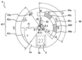
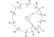
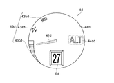
次に、図3、図4、および図5を参照してセンサー付き電子時計Wの詳細な構成および動作について説明する。なお、図4は、図3に示すセンサー付き電子時計の6時側に設けられた円形の小窓(小窓部)である6時情報表示部を拡大して示す平面図である。図5は、図3に示すセンサー付き電子時計の2時側に設けられた円形の小窓(小窓部)である2時情報表示部を拡大して示す平面図である。 Next, a detailed configuration and operation of the sensor-equipped electronic timepiece W will be described with reference to FIGS. 3, 4, and 5. FIG. 4 is an enlarged plan view showing the 6 o'clock information display section which is a circular small window (small window section) provided on the 6 o'clock side of the sensor-equipped electronic timepiece shown in FIG. FIG. 5 is an enlarged plan view showing a 2 o'clock information display portion which is a circular small window (small window portion) provided on the 2 o'clock side of the sensor-equipped electronic timepiece shown in FIG.
図3に示すように、センサー付き電子時計Wは、時刻情報を含む電波を受信し、その時刻情報に基づいて表示時刻を修正する。センサー付き電子時計Wには、機器本体100を構成するダイヤルリング17の内周側に文字板10を含む表示部5が配置され、ダイヤルリング17の外周側には、ダイヤルリング17と同心円状にベゼル19が配置されている。表示部5には、センター指針としての指示針(時針)1、指示針(分針)2、指示針としての計測指示針33が取り付けられている。また、表示部5の指示針(時針)1に対応する位置には、12時間制の目盛5aが環状に形成されている。
As shown in FIG. 3, the sensor-equipped electronic timepiece W receives a radio wave including time information, and corrects the display time based on the time information. In the sensor-equipped electronic timepiece W, the
また、表示部5の10時を示す方向には、副針としての指示針(秒針)34が取り付けられた円形の小窓部である10時情報表示部3が形成されている。また、表示部5の6時を示す方向には、指示針(第1指示針)42および指示針(第2指示針)41が取り付けられた円形の小窓部である6時情報表示部4が形成されている。また、表示部5の2時を示す方向には、指示針(計測指示針)71,72が取り付けられた円形の小窓部である2時情報表示部7が形成されている。
Further, in the direction indicating 10 o'clock on the
上述のように本実施形態では、10時情報表示部3、6時情報表示部4、および2時情報表示部7の3個の円形の小窓部を備える例を示したが、小窓部の配置数はこれに限らない。小窓部の配置数は、1個以上4個以下の数で設けられていることが好ましい。また、小窓部の設けられている位置は、例示の位置に限らず、いずれの位置に配置されてもよい。また、小窓部は、円形に限らず、他の形状であってもよい。
As described above, in the present embodiment, an example including three circular small window portions of the 10 o'clock
何故なら、小窓部を1個以上設けることにより、センサーによって検知されたそれぞれの動作モードの情報を、小窓部を用いて表示することにより検知された情報を分かり易く表示することができる。また、複数の小窓部とすれば、複数のセンサーによって検知されたそれぞれの動作モードの情報を、それぞれ異なる小窓部に表示することができ、種々の情報を更に分かり易く表示することができる。また、小窓部の数を4個以下とすることにより、小窓部を視認性のよい適度な大きさに設定することができる。換言すれば、小窓部を5個以上とすると、表示部の限られたスペースの中では、それぞれの小窓部が小さくなってしまい、表示されている情報の視認性が低下し、一見での視認が困難となる。 This is because by providing one or more small window portions, it is possible to display the information detected by the sensor using the small window portions in an easy-to-understand manner. In addition, if a plurality of small windows are used, information on the respective operation modes detected by the plurality of sensors can be displayed on different small windows, and various information can be displayed more easily. . Further, by setting the number of small window portions to 4 or less, the small window portions can be set to an appropriate size with good visibility. In other words, if the number of small window portions is five or more, each small window portion becomes small in a limited space of the display portion, and the visibility of the displayed information is reduced. Is difficult to see.
図4に示すように、センサー付き電子時計Wの6時情報表示部4には、表示モードとして、時刻を表示する時刻表示モード(TIME)と、標高を表示する標高表示モード(ALT)と、気圧を表示する気圧表示モード(BAR)と、方位を表示する方位表示モード(COM)と、他の指標を表示するオプション表示モード(OP)と、を有している。ここで、オプション表示モードは、例えば生体情報や移動量(運動量)など、他の指標を表示するモードである。
As shown in FIG. 4, the 6 o'clock
また、時刻表示モード(TIME)では、時刻表示機能、および二つ以上の時刻を表示することができるデュアルタイム機能などの時刻表示を行うことができる。また、時刻表示モード(TIME)では、時刻表示に加え、クロノグラフ機能(ストップウォッチ機能)が有効となる。このような時刻表示の機能を備えていることにより、ユーザーの欲する種々の時計(計時)情報を提供することが可能となる。 In the time display mode (TIME), time display such as a time display function and a dual time function capable of displaying two or more times can be performed. In the time display mode (TIME), the chronograph function (stopwatch function) is effective in addition to the time display. By providing such a time display function, it is possible to provide various clock (timekeeping) information desired by the user.
なお、オプション表示モードは、図17に示すように、例えば脈拍センサーなどの生体情報を測定する他のセンサー機器Cが無線または有線でセンサー付き電子時計Wに接続され、該センサー機器Cが測定した生体情報をセンサー付き電子時計Wに表示するモードとすることができる。なお、オプション表示モードは、このような生体情報を表示するモードに限らず、例えば、運動情報やエネルギー消費情報などの第2物理情報を検知する加速度センサーを備えた他のセンサー機器Cによる他のモード(他の指標)に適宜変更可能である。このように、当該センサー付き電子時計Wでは検知できない情報、例えば運動情報やエネルギー消費情報などの第2物理情報や生体情報などを、他のセンサー機器Cによって検知し、その情報をセンサー付き電子時計Wの表示部5に表示することができる。これにより、リストに装着するための限られたスペースのセンサー付き電子時計Wであっても、種々の情報の取得が可能となり、使い勝手を向上させることができる。
As shown in FIG. 17, in the option display mode, another sensor device C that measures biological information such as a pulse sensor is connected to the sensor-equipped electronic timepiece W wirelessly or by wire, and the sensor device C performs the measurement. It can be set as the mode which displays biometric information on the electronic timepiece W with a sensor. The option display mode is not limited to such a mode for displaying biological information. For example, the option display mode is not limited to other sensor devices C including an acceleration sensor that detects second physical information such as exercise information and energy consumption information. It can be changed appropriately to the mode (other indicators). In this way, information that cannot be detected by the sensor-equipped electronic timepiece W, such as second physical information such as exercise information or energy consumption information, or biological information, is detected by another sensor device C, and the information is detected by the sensor-equipped electronic timepiece. It can be displayed on the
ユーザーの位置情報や移動情報(物理量の情報)の内の、いずれの動作モードが表示されているかを示す表示モードは、図3に示すように、6時情報表示部4内の指示針42にて指示される領域の切り替えに応じて切り替えられる。このように、小窓部の少なくとも一つに、複数のセンサーのそれぞれに対応した動作を行なう動作モードとしてのユーザーの位置情報や移動情報(物理量の情報)の内の、各動作モードに対応したモード表示部が設けられる。このような、小窓部によるモード表示部に、いずれの動作モードの情報であるかを示すことにより、複数の情報の内のいずれの動作モードの情報が表示されているかを容易に識別することができる。
As shown in FIG. 3, the display mode indicating which operation mode of the user position information and movement information (physical quantity information) is displayed is indicated on the
表示モードは、制御部110によって管理される。制御部110は、例えばユーザーのボタン14に対する押下操作に応じて、表示モードを切り替える。
The display mode is managed by the
6時情報表示部4は、表示モード(時刻表示モードと、標高表示モードと、気圧表示モードと、方位表示モードと、オプション表示モード)を指示針(第1指示針)42によって表示し、電池残量等を指示針(第2指示針)41によって表示する。
The 6 o'clock
時刻表示モードでは、時刻は、指示針(時針)1と、指示針(分針)2と、10時情報表示部3の指示針(秒針)34と、によって表示される。つまり、6時情報表示部4内の指示針(第1指示針)42が"TIME"の領域44aを指示している場合(表示モードが時刻表示モードである場合)、指示針(時針)1と、指示針(分針)2と10時情報表示部3の指示針(秒針)34とによって時刻が表示される。なお、指示針(時針)1と、指示針(分針)2とは、時刻表示モード以外のいずれの表示モード下でも、時刻(時と分)を示す。
In the time display mode, the time is displayed by the indicator hand (hour hand) 1, the indicator hand (minute hand) 2, and the indicator hand (second hand) 34 of the 10:00
なお、6時情報表示部4の表示部4aには、図4に示すように、「計測中」を示す"MEAS"の文字43bと、センサー付き電子時計Wの電源である二次電池108の残量を示す電池残量メーター43cが配置されている。
As shown in FIG. 4, the
図4に示すように、6時情報表示部4では、標高表示モードに対応する"ALT"の領域44bと、方位表示モードに対応する"COM"の領域44cと、気圧表示モードに対応する"BAR"の領域44dが、"ALT"の領域44b、"COM"の領域44c、"BAR"の領域44dの順に並べて配置されている。
As shown in FIG. 4, the 6 o'clock
また、"ALT"の領域44bの"COM"の領域44c側との反対側に、時刻表示モードに対応する領域("TIME"の領域)44aが配置されている。"BAR"の領域44dの"COM"の領域44c側との反対側に、オプション表示モードに対応する領域("OP"の領域)44eが配置されている。
In addition, a region (“TIME” region) 44 a corresponding to the time display mode is arranged on the opposite side of the “ALT”
指示針42は、"TIME"の領域44aを指示することで、表示モードが時刻表示モードであることを表示する。指示針42は、"ALT"の領域44bを指示することで、表示モードが標高表示モードであることを表示する。指示針42は、"COM"の領域44cを指示することで、表示モードが方位表示モードであることを表示する。指示針42は、"BAR"の領域44dを指示することで、表示モードが気圧表示モードであることを表示する。指示針42は、"OP"の領域44eを指示することで、表示モードがオプション表示モードであることを表示する。そして、指示針42の回転方向(周回方向)において、"ALT"の領域44bと"COM"の領域44cとの間の距離が、"ALT"の領域44bと"BAR"の領域44dとの間の距離よりも短くなっており、かつ、"COM"の領域44cと"BAR"の領域44dとの距離が、"ALT"の領域44bと"BAR"の領域44dとの間の距離よりも短くなっている。
The indicating
各表示モードに対応する領域は、利用シーンを考慮して配置されている。日常生活時では、一般的に、時刻表示モードの使用頻度が高い。このため、"TIME"の領域44a(時刻表示モードに対応)が、最も視認しやすい12時の位置に配置されている。
The area corresponding to each display mode is arranged in consideration of the usage scene. In daily life, the time display mode is generally used frequently. For this reason, the “TIME”
また、登山等のアウトドアスポーツでの利用シーンでは、標高表示モードおよび方位表示モードが利用される可能性が高い。このため、登山等のアウトドアスポーツでの利用シーンで指示針42にて指示される可能性の高い"ALT"の領域44b(標高表示モードに対応)および"COM"の領域44c(方位表示モードに対応)が、"TIME"の領域44aに続いて、この順に配置されている。
In addition, in an outdoor scene such as mountain climbing, there is a high possibility that the altitude display mode and the azimuth display mode are used. For this reason, the “ALT”
なお、方位表示モード("COM"の領域44cに対応)は、登山等のアウトドアスポーツでの利用シーンのほかに、ヨットの航行等のマリンスポーツでの利用シーンでも使用される可能性が高い。また、ヨットの航行等のマリンスポーツでの利用シーンでは、方位表示モード("COM"の領域44cに対応)と同様に、気圧表示モード("BAR"の領域44dに対応)が利用される可能性が高い。このため、"COM"の領域44cの隣に"BAR"の領域44d(気圧表示モードに対応)が配置されている。
Note that the orientation display mode (corresponding to the “COM”
このように、同一の利用シーンで使用される可能性の高い領域間の距離("ALT"の領域44bと"COM"の領域44cとの間の距離や、"COM"の領域44cと"BAR"の領域44dとの間の距離)が、同一の利用シーンで使用される可能性の低い領域間の距離("ALT"の領域44bと"BAR"の領域44dとの間の距離)よりも短い。このため、同一の利用シーンで指示される可能性の高い領域の間での指示針42の指示位置の切り替え時間を、同一の利用シーンで指示される可能性の低い領域の間での指示針42の指示位置の切り替え時間よりも短くできる。よって、同一の利用シーンにおける指示針42の指示位置の切り替えに時間がかかりすぎてしまうことを抑制可能になる。
As described above, the distance between the regions that are likely to be used in the same usage scene (the distance between the “ALT”
標高表示モードでの標高、気圧表示モードでの気圧、オプション表示モードでの脈拍は、図3に示したセンサー付き電子時計Wの2時側の円形の2時情報表示部7と、環状のダイヤルリング17に100分割された目盛および計測指示針33によって表示される。
The altitude in the altitude display mode, the atmospheric pressure in the atmospheric pressure display mode, and the pulse in the option display mode are the circular 2 o'clock
具体的には、2時情報表示部7では、計測値(標高、気圧、脈拍)の1000の位の値を計測指示針71が表示し、該計測値の100の位の値を計測指示針72が表示する。計測指示針33は、該計測値の10の位の値と1の位の値とをダイヤルリング17の目盛(100分割)を用いて表示する。例えば、6時情報表示部4内の指示針42が"ALT"の領域44bを指示している場合、2時情報表示部7と計測指示針33とによって、標高の計測値が表示される。また、6時情報表示部4内の指示針42が"BAR"の領域44dを指示している場合、2時情報表示部7と計測指示針33とによって、気圧の計測値が表示される。
Specifically, in the 2 o'clock
方位表示モードでの、例えば北の方位は、計測指示針33が北の方角を指し示すことによって表示される。つまり、6時情報表示部4内の指示針42が"COM"の領域44cを指示している場合、計測指示針33によって北の方角が表示される。この場合、2時情報表示部7では、計測指示針71,72に目盛り74a(数値「0」)が表示される。
In the azimuth display mode, for example, the north azimuth is displayed by the
時刻表示モードでの時刻は、時を示す指示針(時針)1と、分を示す指示針(分針)2と、秒を示す10時側の円形の小窓部である10時情報表示部3の指示針(秒針)34とによって表示される。つまり、6時情報表示部4内の指示針42が"TIME"の領域44aを指示している場合、指示針(時針)1と指示針(分針)2と10時情報表示部3の指示針(秒針)34とによって、時刻が表示される。なお、指示針(時針)1と指示針(分針)2とは、他のいずれの表示モード下でも、時刻(時と分)を示す。ここで、図3および図4について補足すると、図3は、表示モードが標高表示モード("ALT")であるときのセンサー付き電子時計Wを示した図であり、図4は、表示モードが時刻表示モード("TIME")であるときの6時情報表示部4を示した図である。
The time in the time display mode includes an indicating hand (hour hand) 1 indicating the hour, an indicating hand (minute hand) 2 indicating the minute, and a 10 o'clock
表示部5には、計測指示針33が取り付けられている。計測指示針33は、例えば、標高表示モード下では、気圧センサーからの出力に基づいて算出された標高の値を、計測結果として、0〜99のうち該当する値を表示する。具体的には、計測指示針33は、表示部5の外周部のダイヤルリング17に100分割された目盛を用いて、標高の計測結果における1の位および10の位の数字を表示する。表示部5の2時を示す方向には、標高の計測結果における100の位と1000の位を表示する計測指示針71および72が取付けられた2時情報表示部7が形成されている。図示の例においては、計測指示針71および72は標高1400mを示し、計測指示針33は標高65mを示している。これにより、ユーザーは、標高が1465mであることを知ることができる。
A
表示部5の6時を示す方向に配置された6時情報表示部4に取付けられた指示針42は第1情報を表示し、指示針41は第2情報を表示する。ここで、第1情報、および第2情報は、時刻以外の情報である。
The
図4に詳細に示すように、6時情報表示部4の表示部4aは、第1表示領域44と第2表示領域43とを有する。第1表示領域44と第2表示領域43は、互いに重複しないように隣り合って配置されている。第2表示領域43は、同心軸40を中心とする中心角がθ1(108°)の扇状をなす範囲となっている。第2表示領域43は、指示針41の指示可能な領域の一例である。第1表示領域44は、同心軸40を中心とする中心角がθ2(129°)の円弧状の範囲となっている。第1表示領域44は、指示針42の指示可能な領域の一例である。第1表示領域44および第2表示領域43は、同心軸40における回転角度によって複数の表示単位に分割されている。
As shown in detail in FIG. 4, the
第2表示領域43には、電池残量を示す領域(電池残量メーター43c)と、センサー付き電子時計Wの動作状態を示す領域(アイコン43aおよび文字43b)とが設けられている。指示針42は、電池残量を示す領域を指示することで電池残量を表示する。また、指示針42は、センサー付き電子時計Wの動作状態を示す領域を指示することでセンサー付き電子時計Wの動作状態を表示する。センサー付き電子時計Wの動作状態としては、時刻情報を含む電波の受信停止を意味する「無線停止中」と、指示針42が表示する表示モードに対応する所与の計測(時刻や標高や方位や気圧の計測)を実行中であることを意味する「計測中」が含まれる。
The
本実施形態では、第2表示領域43には、電池残量メーター43cと、無線停止中を示すアイコン43aと、「計測中」を示す"MEAS"の文字43bが設けられている。"MEAS"の文字43bが位置する領域は、第1表示領域44と隣り合っている。
In the present embodiment, the
指示針41は、第2表示領域43において、同心軸40を中心とする回転により、電池残量とセンサー付き電子時計Wの動作状態とを択一的に表示する。一方、指示針42は、第1表示領域44において、同心軸40を中心とする回転により、現在の表示モード(時刻表示モード、標高表示モード、方位表示モード、気圧表示モード、オプション表示モードのいずれか)を表示する。なお、各表示モードは、該表示モードでの測定値の種類も示す。例えば、時刻表示モードは、測定値の種類として時刻を示し、標高表示モードは、測定値の種類として標高を示し、方位表示モードは、測定値の種類として方位を示し、気圧表示モードは、測定値の種類として気圧を示し、オプション表示モードは、測定値の種類として生体情報を示す。
The
指示針42は、指示針41の回転を減速して指示針42を回転させる減速機構によって駆動される。指示針41は、"MEAS"位置から"E"位置(空;エンプティー位置)までの108°の範囲を、"F"位置(フル位置)を中心に±54°の範囲で移動して第2情報(電池残量とセンサー付き電子時計Wの動作状態)を表示する。
The
指示針41が"MEAS"位置から"E"位置までの108°の範囲を移動する場合、指示針42は、上述した減速機構によって、4.5°の範囲で表示位置を移動する。ここで、各表示モードの表示単位("TIME"の領域、"ALT"の領域、"COM"の領域、"BAR"の領域、"OP"の領域)44a〜44eは、角度30°(=0±15°)の範囲である。このため、指示針41の回転に伴って指示針42が4.5°の範囲で回転しても、指示針42の指示する領域(表示単位)は変更されず、ユーザーが指示針42の指示する表示モードを誤読する可能性を低くすることができる。角度30°(=0±15°)は、角度dθの一例である。なお、センサー付き電子時計Wを携帯したユーザーが航空機に搭乗中であるときのように無線機能(時刻情報を含む電波の受信機能)が使えないときに、ユーザーがボタン13〜15のいずれかを操作すると、指示針41が無線停止中を示すアイコン43aを指示するようになっている。
When the indicating
第1表示領域44は、"TIME"の領域44aと、"ALT"の領域44bと、"COM"の領域44cと、"BAR"の領域44dと、"OP"の領域44eとを含む。第1表示領域44では、指示針42が各表示モードの表示単位("TIME"の領域、"ALT"の領域、"COM"の領域、"BAR"の領域、"OP"の領域)44a〜44eを択一的に指示することにより、現在の表示モードが表示される。
The
本実施形態では、帯状の円弧形をなす領域に表記された文字によって、各表示モードの表示単位44a〜44eが示されている。具体的には、表示単位44a〜44eとして、"TIME"(時刻)、"ALT"(標高)、"COM"(コンパス:方位)、"BAR"(気圧)、"OP"(オプション)が示されている。
In the present embodiment, the
指示針42の指示位置にて表示される表示モード、つまり、第1表示領域44で表示される表示モードは、ボタン14の押下操作で切り替えることができる。例えば、ボタン14が1回押されるごとに、指示針41が360°右回転するとともに、指示針42が、角度dθの一例である30°右回転する。このため、ボタン14が1回押されるごとに、表示モードが、時刻表示モード("TIME"モード)から標高表示モード("ALT"モード)、方位表示モード("COM"モード)、気圧表示モード("BAR"モード)、オプション表示モード("OP"モード)に順次切り替わる。
The display mode displayed at the position indicated by the pointing
また、指示針42がオプション表示モード("OP"モード)を指し示している状況でボタン14が押されると、指示針42が逆転して"TIME"の領域44a(時刻表示モードの領域)へ移動する。なお、図4に示した例では、指示針41が電池残量"F"(フル)を示し、指示針42が時刻表示モードを示している。
When the
6時情報表示部4の表示部4aの6時を示す方向には、カレンダーを表示する日車6を透視するための情報表示部5bが形成されている。情報表示部5bは、第1表示領域44および第2表示領域43と重複しない領域において、同心軸40を通りかつ12時側と6時側とを結ぶ直線上に固定配置された一例である。情報表示部5bは、カレンダーの日付を表示する。情報表示部5bが、同心軸40を通り12時側と6時側とを結ぶ直線上に、固定配置されることで、センサー付き電子時計W全体のシンメトリーなデザインが実現される。なお、日車6は、日付の数字が表記されたリング状の表示部材であり、図示しない駆動系により回転動作する。
In the direction indicating 6 o'clock of the
図4は、指示針41の回転範囲と連動する指示針42の回転範囲を示した図である。図4に示した例では、指示針42は、表示単位44a("TIME"の領域)を指し示している。指示針42が表示単位44aを指示している場合、表示モードは、時刻表示モードとなる。時刻表示モードでは、時刻表示に加え、クロノグラフ機能(ストップウォッチ)が有効となる。
FIG. 4 is a view showing the rotation range of the
図4に示した状態でボタン13が押下されると、図3に示した計測指示針33が1/5秒刻みで運針を開始し、同時に、図4に示したように6時情報表示部4の指示針41が、電池残量の"F"を示す位置から54°右回転し、計測中を意味する"MEAS"の文字43bを示す位置に移動してくる。このとき、指示針42は、指示針41の回転に連動して4.5°右に回転する。ここで、"TIME"の領域の表示単位44aは、30°の幅を持っている。したがって、指示針42は、依然として、"TIME"の領域の表示単位44aを指し示すことになる。同様に、指示針41が、電池残量の"F"を示す位置から54°左回転して電池残量の"E"を示す場合、指示針42は、4.5°左回転するが、依然として"TIME"の領域の表示単位44aを指し示すことになる。
When the
図5に示す2時情報表示部7は、標高表示モードでの標高、気圧表示モードでの気圧、オプション表示モードでの脈拍、および、ストップウォッチ機能での時間を、計測指示針33と協働して、目盛り74a〜74jと計測指示針71および計測指示針72によって表示する。2時情報表示部7を構成する文字板73は、数値で示された目盛り74a〜74jを備えた部材の一例である。図5に示す構成例では、目盛り74a〜74jは、それぞれ、数値「0」〜「9」で示されている。
The 2 o'clock
制御部110は、数値で示される物理量(標高の計測値、気圧の計測値、脈拍の計測値、およびストップウォッチ機能での時間の計測値など)を、計測指示針71,72と目盛り74a〜74jとを用いて表示する。この際、制御部110は、目盛り74a〜74jの数値を、目盛り74a〜74jの数値に対して10n(nは0以上の整数)を乗算した値として用いる。ここで、標高の計測値、気圧の計測値および脈拍の計測値の各々は、数値で示される物理量(物理量A)の一例である。一方、ストップウォッチ機能での時間の計測値は、数値で示され物理量Aとは異なる種類の物理量(物理量B)の一例である。
The
制御部110は、物理量Aを計測指示針71,72と目盛り74a〜74jとを用いて表示する場合と、物理量Bを計測指示針71,72と目盛り74a〜74jとを用いて表示する場合とで、上述したnとして異なる値を用いる。
The
本実施形態では、制御部110は、物理量Aを表示する場合、計測指示針71と目盛り74a〜74jとの組み合わせについては、目盛り74a〜74jの数値(例えば「2」)を、その数値(「2」)に対して103(=n)(=1000)を乗算した値(「2000」)として用いる。この場合、制御部110は、上述したnとして「3」を用いる。
In the present embodiment, when displaying the physical quantity A, the
一方、物理量Bを表示する場合、制御部110は、計測指示針71と目盛り74a〜74jとの組み合わせについては、目盛り74a〜74jの数値(例えば「2」)を、その数値(「2」)に対して101(=n)(=10)を乗算した値(「20」)として用いる。この場合、制御部110は、上述したnとして「1」を用いる。
On the other hand, when displaying the physical quantity B, the
また、制御部110は、物理量Aを表示する場合、計測指示針72と目盛り74a〜74jとの組み合わせについては、目盛り74a〜74jの数値(例えば「2」)を、その数値(「2」)に対して102(=n)(=100)を乗算した値(「200」)として用いる。この場合、制御部110は、上述したnとして「2」を用いる。
Further, when displaying the physical quantity A, the
一方、物理量Bを表示する場合、制御部110は、計測指示針72と目盛り74a〜74jとの組み合わせについては、目盛り74a〜74jの数値(例えば「2」)を、その数値(「2」)に対して100(=n)(=1)を乗算した値(「2」)として用いる。この場合、制御部110は、上述したnとして「0」を用いる。
On the other hand, when displaying the physical quantity B, the
したがって、物理量A(標高の計測値、気圧の計測値および脈拍の計測値のいずれか)が表示される場合、物理量Aの1000の位の値が計測指示針71で表示され、物理量Aの100の位の値が計測指示針72で表示される。なお、物理量Aの10の位の値および1の位の値については、制御部110は、計測指示針33を駆動するステップモーター(不図示)を駆動することによって、物理量Aの10の位の値および1の位の値を、計測指示針33と、ダイヤルリング17に100分割された目盛り(100分割)と、を用いて表示する。
Therefore, when the physical quantity A (any one of the measurement value of altitude, the measurement value of atmospheric pressure, and the measurement value of pulse) is displayed, the value of the physical quantity A in the order of 1000 is displayed by the
一方、物理量B(ストップウォッチ機能での時間の計測値)が表示される場合、物理量Bにおける分の10の位の値が計測指示針71で表示され、物理量Bにおける分の1の位の値が計測指示針72で表示される。なお、物理量Bにおける秒の値については、制御部110は、計測指示針33を駆動するステップモーター(不図示)を駆動することによって、物理量Bにおける秒の値を、計測指示針33と、表示部5に設けられた12時間制の目盛り5aと、を用いて表示する。この際、制御部110は、計測指示針33を1/5秒ごとに運針し60秒で1周させる。
On the other hand, when the physical quantity B (measured value of time by the stopwatch function) is displayed, the tenth digit value of the physical quantity B is displayed by the
上記指示針の駆動系について図6、および図7を参照して説明する。図6は、本実施形態に係る6時情報表示部4の構成を示す断面図であり、図7は、図6に示す駆動系等の平面図である。なお、図6、および図7は、指示針42および指示針41の駆動系を例示している。
The drive system for the indicating needle will be described with reference to FIGS. 6 and 7. FIG. 6 is a cross-sectional view showing a configuration of the 6 o'clock
図6および図7に示すように、指示針42と指示針41とは、共通のステップモーター51で駆動され中間車152または中間車154を介して同軸上で回転する。センサー付き電子時計Wには、駆動源であるステップモーター51からの駆動力によって、指示針41を第1の速度で回転させる動力伝達機構Aと、指示針41の回転を減速して指示針42を第2の速度で回転させる減速機構Bとが設けられている。ステップモーター51と動力伝達機構Aと減速機構Bとで駆動部が構成される。動力伝達機構Aと減速機構Bとは、ステップモーター51を共通の駆動源として用いている。動力伝達機構Aと減速機構Bでは、一部の歯車等が共通に用いられている。具体的に、動力伝達機構Aには、中間車152と電池残量表示車153とが含まれ、減速機構Bには、電池残量表示車153と中間車154とモード表示車156とが含まれる。電池残量表示車153は、指示針41が、電池残量メーター43c(図4参照)だけでなく、無線停止中を意味するアイコン43a(図4参照)や、計測中を示す"MEAS"の文字43b(図4参照)を択一的に指示できるように回転する。
As shown in FIGS. 6 and 7, the
詳述すると、ステップモーター51は、指示針42および指示針41を駆動するための駆動源である。ステップモーター51は、コイルブロック、ステータおよびローター151aを備えている。ステップモーター51は、駆動パルスが供給されると回転する。コイルブロックは、高透磁率材からなる磁芯、それに巻かれたコイル、その両端を導通可能に処理したコイルリード基板、およびコイル枠を含んで構成されている。ステータは、磁芯と同様、高透磁率材から構成されている。ローター151aには、ローター磁石に金属製のかなが取り付けられている。ステップモーター51等の駆動源の電源としては、例えば、二次電池108が用いられ、3Vの直流電圧が印加されるようになっている。
More specifically, the
また、ステップモーター51は、CPU−IC等の制御部110から出力される駆動パルスによって回転する。CPU−ICは、センサー付き電子時計W全体の動作を制御する演算処理装置である。CPU−ICは、ユーザーによるボタン13〜15の操作等を受け付けるとともに、加速度センサー101、圧力センサー102、方位センサー103、通信部104および受信部105と接続されている。CPU−ICは、電池残量を計測する残量計測部、表示モードを制御する表示モード制御部としても機能する。また、CPU−ICは、ユーザーの操作に応じてステップモーター51の駆動パルスを出力し、6時情報表示部4における各表示の制御を実行する。
Further, the
制御部110は、ステップモーター51を駆動することによって、指示針42と指示針41を駆動する。また、制御部110は、加速度センサー101、圧力センサー102、および方位センサー103の計測値、通信部104が取得した生体情報などの第2物理情報、受信部105を用いて取得した時刻情報にて修正された内部時刻を表示するために、指示針(時針)1、指示針(分針)2、指示針(秒針)34、日車6、計測指示針33,71,72の各々を、不図示の駆動機構を介して駆動する。
The
図6に示したように、ステップモーター51のローター151aは、中間車152の下部歯車152aに噛合され、下部歯車152aと一体的に回転する上部歯車152bを介して、電池残量表示車153の下部歯車153aを回転させる。電池残量表示車153は、回転軸155と一体的に回転する。回転軸155は、前述の同心軸40を中心として回転する。回転軸155が、電池残量表示車153を介して同心軸40を中心に回転することにより、指示針41が運針される。
As shown in FIG. 6, the
また、電池残量表示車153の上部歯車153bは、下部歯車153aと一体的に回転する。電池残量表示車153は、上部歯車153bを介して、中間車154の下部歯車154aを回転させる。中間車154の下部歯車154aは、地板150の表側(表示部4a側)に配置された上部歯車154bと一体的に回転する。中間車154は、上部歯車154bを介して、モード表示車156の歯車156aを回転させる。モード表示車156は、内部が中空の筒状部分156bを有している。筒状部分156bは、回転軸155の外周面側に嵌合されている。筒状部分156bは、回転軸155と同様に同心軸40を中心として回転する。筒状部分156bの回転によって、指示針42が運針される。
Further, the
第1表示領域44は、同心軸40における回転角度dθによって複数の表示単位に分割されている(図4参照)。減速機構Bの減速比を1/Nとしたときに、式1が満たされるように、角度dθは設定されている。
dθ>θ1/N…式1
The
dθ> θ1 /
本実施形態において、角度dθは30°に設定されている。詳述すると、指示針41については、ステップモーター51が40ステップしたときに指示針41が1周(360°回転)するように、動力伝達機構Aにおける各歯車の減速比が設定されている。このため、指示針41は、360°を40で割った角度ごとに運針する。一方、指示針42については、指示針41が1周する間に指示針42が1個の表示単位分である30°回転するように、減速機構Bの減速比が設定されている。ボタン14が1回押下されると、指示針41が1周(360°)し、指示針42が一目盛(1表示単位)分(30°)だけ進んで、表示モードが切り替わる。
In the present embodiment, the angle dθ is set to 30 °. Specifically, the reduction ratio of each gear in the power transmission mechanism A is set so that the
減速機構Bの減速比1/N、指示針41が振れる最大範囲の角度θ1、第1表示領域44における1個の表示単位の角度dθを式1のように定めたのは、以下の理由による。
The reason why the
指示針41が振れる最大範囲は角度θ1である。減速機構Bの減速比は1/Nであるから、指示針41が所定角度だけ回転すると、指示針42が該所定角度の1/Nだけ回転する。したがって、指示針41が角度θ1だけ回転したとしても、指示針42は角度θ1/Nしか回転しないことになる。ここで、dθ>θ1/Nとなるので、仮に、指示針41が角度θ1だけ回転しても、指示針42の振れ角度は、第1表示領域44における表示単位の角度dθ未満となる。よって、指示針41が指示する情報が変更された場合に、指示針42が指示する情報(表示モード)が誤読される確率を低減することができる。
The maximum range in which the
なお、式1の替わりに式2の関係を充足するように、角度dθが設定されてもよい。
dθ/2>θ1/N…式2
この場合、指示針41が角度θ1だけ回転すると、指示針42は角度θ1/Nだけ回転するが、角度θ1/Nは、第1表示領域44における表示単位の角度dθの半分未満となる。したがって、指示針41の回転が指示針42へ与える影響をより低減することができる。
Note that the angle dθ may be set so as to satisfy the relationship of
dθ / 2> θ1 /
In this case, when the
以上説明した本実施形態に係るセンサー付き電子時計Wによれば、6時情報表示部4では、"ALT"の領域44bと、"COM"の領域44cと、"BAR"の領域44dとが、"ALT"の領域44b、"COM"の領域44c、"BAR"の領域44dの順に並べて配置されている。そして、指示針42の回転方向(周回方向)において、"ALT"の領域44bと"COM"の領域44cとの間の距離が"ALT"の領域44bと"BAR"の領域44dとの間の距離よりも短く、"COM"の領域44cと"BAR"の領域44dとの距離が"ALT"の領域44bと"BAR"の領域44dとの間の距離よりも短くなっている。
According to the sensor-equipped electronic timepiece W according to the present embodiment described above, in the 6 o'clock
ユーザーは、利用シーンに応じて指示針42の指示領域を変更することで、標高表示モードと方位表示モードと気圧表示モードとを切り替えることになる。例えば、登山等のアウトドアスポーツでの利用シーンでは、標高表示モードと方位表示モードが使用される可能性が高い。また、ヨット等のマリンスポーツでの利用シーンでは、気圧表示モードと方位表示モードが使用される可能性が高い。本実施形態では、同一の利用シーンで使用される可能性の高い領域間の距離(例えば、登山時の利用シーンで共に使用される可能性の高い"ALT"の領域44bと"COM"の領域44cとの間の距離や、ヨットの航行時の利用シーンで共に使用される可能性の高い"COM"の領域44cと"BAR"の領域44dとの距離)が、同一の利用シーンで使用される可能性の低い領域間の距離("ALT"の領域44bと"BAR"の領域44dとの間の距離)よりも短い。よって、同一の利用シーンにおいて指示針42の指示位置の切り替えに時間がかかりすぎてしまうことを抑制可能になる。
The user switches the altitude display mode, the azimuth display mode, and the atmospheric pressure display mode by changing the indication area of the
また、ユーザーは、センサー付き電子時計Wの状態を把握する際に、指示針41の指示位置を視認してセンサー付き電子時計Wの動作状態や電池残量を確認するとともに、指示針42の指示位置を視認して現状の表示モードを確認する可能性がある。本実施形態では、指示針42が指示する第1表示領域44と、指示針41が指示する第2表示領域43とが隣り合っている。このため、ユーザーは、センサー付き電子時計Wの状態を把握する際に、指示針42が表示する表示モードと、指示針41が表示する動作状態や電池残量を、一度に視認可能になり、視線を大きく動かす必要が低くなる。よって、指示針42の表示内容と指示針41の表示内容とについて高い視認性を得ることが可能になる。
Further, when the user grasps the state of the sensor-equipped electronic timepiece W, the user confirms the operation position of the sensor-equipped electronic timepiece W by checking the indication position of the
本実施形態では、指示針42と指示針41は、同軸上で回転する。このため、指示針42と指示針41が異なる軸でそれぞれ回転する場合に比べて、省スペース化を図ることが可能になる。
In the present embodiment, the
本実施形態では、指示針41が表示する動作状態は、指示針42が表示する表示モードに対応する計測を実行中であることを意味する計測中状態を含む。そして、計測中状態に対応する"MEAS"の文字43bの領域は、指示針42が指示する第1表示領域44と隣り合っている。このため、ユーザーは、互いに関連する、指示針42が指示する表示モードと、その表示モードに対応する計測が実行中であるかの表示を、一度に視認可能になる。
In the present embodiment, the operation state displayed by the
本実施形態では、二次電池108における電池残量を示す電池残量メーター43cの"F"(フル)の隣に、無線停止中を示すアイコン43aが配置されている。時刻情報を含む電波の受信(無線通信)は、比較的使用電力が大きい。このため、電池残量が満充電("F")に近いことが、無線通信を行うための条件となる。よって、無線通信を行っている間、指示針41は、電池残量メーター43cの"F"を指し示している確率が高いと推測できる。したがって、無線通信を行っている状況から無線停止に早く切り替わるためには、無線停止中を示すアイコン43aを、電池残量の"F"の隣に配置することが望ましい。
In the present embodiment, an
本実施形態では、1つのステップモーター51からの駆動力によって、指示針41と指示針42とを同軸上で駆動させる。このため、ステップモーターの数を減らすことができ、駆動源からの駆動力を伝達するための歯車等の部品点数も減らすことができ、駆動源や歯車等の部品が省スペースでの配置が可能となり、時計全体の小型化、デザイン上の自由度の向上を図ることができる。
In the present embodiment, the
本実施形態では、第2表示領域43を中心角がθ1(108°)の範囲とし、第1表示領域44を中心角がθ2(129°)の、第2表示領域43と重複しない範囲とし、第2表示領域43と第1表示領域44とが同心軸40を挟んで配置されている。このため、第2表示領域43と第1表示領域44とが互いに重畳しないよう対向配置されることとなり、第1情報および第2情報を区別しやすくして、第1情報および第2情報の読み取りやすさを向上させることができる。
In the present embodiment, the
本実施形態では、第2表示領域43および第1表示領域44と重複しない領域に、同心軸40を通るとともに12時側と6時側とを結ぶ直線上に、第3情報を表示する第3表示領域として、カレンダーの日車6を表示する情報表示部5bが固定配置されている。このため、デザインのシンメトリー性を強調することができ、デザインの安定性を高めることができる。
In the present embodiment, the third information is displayed on a straight line passing through the
(変形例1)
なお、本発明は、上述した実施形態に限定されるものではなく、種々の変形を加えることができる。例えば、上述した指示針42の替わりに、同心軸40を中心に回転する帯状の円弧形の回転板とすることができる。図8A、図8B、および図8Cは、変形例1に係る6時情報表示部を示し、図8Aは表示モードを表示させる場合の仕組みを示す平面図であり、図8は変形例1に用いる回転板の一例を示す平面図であり、図8Cは変形例1に用いる回転板の他の例を示す平面図である。
(Modification 1)
In addition, this invention is not limited to embodiment mentioned above, A various deformation | transformation can be added. For example, instead of the
図8Aに示すように、6時情報表示部4内に、下面の回転板48aが見えるような矩形の開口部47を表示部4aに開口させる。この6時情報表示部4には、本変形例では、上述した第1実施形態と同様の、第1情報である電池残量を示す電池残量メーター43cやモード(無線停止中を示すアイコン43a,計測中を示す"MEAS"の文字43b)が表示されており、開口部47は、これら電池残量メーター43cと"MEAS"の文字43bとの間に配置されている。指示針41は、アイコン43aの位置から電池残量メーター43cの"E"までの範囲で表示し、指示針41は、電池残量表示から表示モードに移行する場合には、開口部47をスキップするように制御される。
As shown in FIG. 8A, in the 6 o'clock
開口部47に下面に配置される回転板48aは、図8Bに示すような半円状の形状であり、同心軸140(同心軸40)を中心として、ステップモーター51からの駆動力が、減速機構Bによって伝達され、第2の速度で駆動される。回転板48aの表面には、図中点線で示す帯状の円弧形をなす第2の表示領域Zが、同心軸140(同心軸40)における角度dθで5個の表示単位に分割され、分割された各表示単位に表記された文字によって、"TIME"(時刻表示)モード、"ALT"(標高表示)モード、"COMP"(コンパス)モード、"BAR"(気圧)モード、"OP"(オプション)モードを示すようになっている。ここで、第2情報たるモードは、第1番目から第K番目の要素の一つを示すものである。この例では、Kは「5」であり、"TIME"、"ALT"、"COMP"、"BAR"、および"OP"が各要素となる。
The
これらの表示モードは、8時側のボタン14の押下操作で切り替えができ、ボタン14を1回押すごとに指示針41が360°右回転するとともに、回転板48aがdθ分の30°右回転し、"TIME(時刻表示)"から"ALT"(標高表示)モード、"COM"(コンパス)モード、"BAR"(気圧)モード、"OP"(オプション)モードに順次切り替わり、OPモード位置でボタン14を押すと回転板48aが逆転し左位置の"TIME"へ移動する。なお、図示した例では、指示針41で電池残量"F"を示し、開口部47には"TIME"モード(時刻表示)が示されている。
These display modes can be switched by pressing the
また、この回転板48aの替わりに、図8Cに示すような円形の回転板48bとしてもよい。回転板48bでは、円形の形状をしており、表示モードが2回ずつ繰り返されて表記されている。すなわち、第2情報が、第1番目から第K番目の要素の一つを示すものである場合、第2表示領域Zに形成される複数の表示単位の数は2K個となる。そして、第2表示領域Zには、回転板48bの回転方向の順に第1番目から第K番目の各要素が並ぶ。具体的には、"TIME"、"ALT"、"COM"、"BAR"、および"OP"の順に各要素が並んでいる。そして、K番目の要素である"OP"に続いて第1番目から第K番目の各要素である"TIME"、"ALT"、"COM"、"BAR"、および"OP"が並んでいる。ここで、開口部47から第K番目の要素である"OP"が視認できている状態で、第2情報が第1番目の要素"TIME"を指示するように変更されたとする。この場合、第K番目の要素"OP"の次の要素が第1番目の要素"TIME"であるので、ステップモーター51を逆転させ第K−1番目の要素→第K−2番目の要素→…→第1番目の要素と移行させるよりも小さな回転角で第K番目の要素"OP"から第1番目の要素"TIME"へ移行させることが可能となる。この結果、移動時間を短縮することができる。また、第2情報は、開口部47から視認されることになるので、回転板48aに第1番目から第K番目の要素を2回並べてもユーザーが混乱することはない。
Further, instead of the
また、6時情報表示部4内の矩形の開口部47に露出する回転板48a,48bに替えて、開口部47に対応して配置された、例えば液晶ディスプレイなどを用いたデジタル表示部を用いることができる。この場合、第1情報である電池残量を示す電池残量メーター43cやモード(無線停止中を示すアイコン43a、計測中を示す"MEAS"の文字43b)を指示する指示針41と、デジタル表示部に表示される回転板48a,48bに相当するデジタル表示を併用した表示とすることができる。
Further, instead of the
上述した第1実施形態および変形例1のセンサー付き電子時計Wによれば、ユーザーに装着された状態で、現在時刻、およびユーザーの位置情報や移動情報(物理量の情報)などが、指示針1,2,33,34,41,42,71,72によって表示されるため、表示の視認性が高まり、比較的小型の表示部5の内に表示させることが可能となる。これにより、リスト機器としてのセンサー付き電子時計Wを装着しても、一見通常の腕時計と同様な装着が可能となり、装着性を高めることが可能となるとともに、センサー付き電子時計Wとしてのファッション性を向上させることが可能となる。
According to the sensor-equipped electronic timepiece W of the first embodiment and the first modification described above, the current time, the user's position information, movement information (physical quantity information), and the like are displayed on the
また、電源部106に、例えば太陽光などの光エネルギーをソーラーセルを用いて電気エネルギーに変換する光発電システム、もしくはユーザーの腕の動きによって回動する回転錘の運動エネルギーを電気エネルギーに変換する所謂自動巻き発電システムなどによって構成される自己発電機能を備えた発電部120が備えられている。また、センサー付き電子時計Wは、自己発電機能を有する発電部120を有していることにより、消費電力を自己発電によって賄うことができ、比較的消費電力の大きなGPSなどの機能や複数のセンサーなどを搭載することができる。また、電源部106において、ユーザーの入手が容易な自然エネルギーである太陽光を用いたり、ユーザー(装着者)の腕の動きを用いたりして発電するため、環境に影響を生じない所謂クリーンエネルギーを動力源(電源)とすることができる。
In addition, the
これらにより、ユーザーが一般生活において欲する情報である、例えばGPS(Global Positioning System)による位置情報などを含む情報を得ることが可能なリスト機器としてのセンサー付き電子時計Wを提供することができる。 Thus, it is possible to provide the sensor-equipped electronic timepiece W as a wrist device capable of obtaining information that the user desires in general life, for example, information including position information by GPS (Global Positioning System).
また、センサー付き電子時計Wは、情報として物理量を検知する、加速度センサー101、圧力センサー102、および方位センサー103のいずれかのセンサーを含むことにより、例えばGPS(Global Positioning System)による位置情報に加えて、ユーザーの欲する情報として、ユーザー(装着者)の移動方向や標高差を含む移動量(運動量)などの情報を容易に得ることができる。
In addition, the sensor-equipped electronic timepiece W includes any one of the
(変形例2)
なお、6時情報表示部4は、図9に示す変形例2のように、円形の小窓部である6時情報表示部4に相当するデジタル表示部4adで構成する6時情報表示部4dとすることもできる。図9は、変形例2に係る6時情報表示部を示す平面図である。なお、変形例2において、6時情報表示部4dで表示される情報はデジタル表示され、他の表示は、指示針(時針)1、指示針(分針)2、10時情報表示部3の指示針(秒針)34、および2時情報表示部7の計測指示針71,72などによって指示されるアナログ表示が行われる。即ち、変形例2に係る表示方法は、位置情報、物理情報、生体情報などは、アナログ表示およびデジタル表示を併用して表示される。
(Modification 2)
In addition, the 6 o'clock
変形例2に係る6時情報表示部4dは、図9に示すように、電池残量を示す電池残量メーター43cd、モード(無線停止中を示すアイコン43ad、計測中を示す"MEAS"の文字43bd)を指示する指示針41d、標高を示す表示モードである"ALT"表示44ad、およびカレンダーを表示するカレンダー表示部6dが、デジタル表示されている。即ち、変形例2に係る6時情報表示部4dは、例えば液晶ディスプレイ(LCD:Liquid Crystal Display)を用いた表示ディスプレイ(液晶表示パネル)などによって構成される。なお、表示ディスプレイとしては、電気泳動ディスプレイ(EPD:Electrophoretic Display)モジュール、有機エレクトロルミネッセンスディスプレイ(OLED:organic electro-luminescence Display)モジュールなどを用いることができる。また、表示モードとしては、標高を示す表示モードである"ALT"の他に、"TIME"(時刻)、"COM"(コンパス:方位)、"BAR"(気圧)、"OP"(オプション)などが選択されて表示される。
As shown in FIG. 9, the 6 o'clock
このように、表示部5において、指示針(時針)1、指示針(分針)2、指示針(秒針)34、および計測指示針71,72などによって指示されるアナログ表示と、6時情報表示部4dによって指示されるデジタル表示を併用することにより、提示できる情報の種類や情報量を増やすことができる。
In this way, on the
なお、変形例2では、6時情報表示部4dを用いたデジタル表示を行う構成で説明したがこれに限らず、例えば、10時情報表示部3や2時情報表示部7をデジタル表示とすることができる。
In the modified example 2, the digital display using the 6 o'clock
(変形例3)
次に、センサー付き電子時計Wの変形例3について、図10を参照して説明する。図10は、変形例3に係る受信部の構成を示す機能ブロック図である。変形例3のセンサー付き電子時計Wは、図10に示されているように、時刻情報としての、異なる二つの電波をそれぞれ受信する第1電波受信部105a、および第2電波受信部105bを受信部205に備えることができる。具体的に、受信部205は、アンテナ109aと接続された第1電波受信部105aと、アンテナ109bと接続された第2電波受信部105bと、を含む。なお、第1電波受信部105aとアンテナ109aとの構成が、第1実施形態に示した受信部105に相当する。また、第2電波受信部105bとアンテナ109bとの構成が、第2受信部に相当する。
(Modification 3)
Next,
第1電波受信部105aは、アンテナ109aによって、GPS衛星8(図1A参照)からのGPS時刻情報と軌道情報とを含む高周波の電波(衛星信号)を受信する。GPS衛星8からの電波(衛星信号)は、例えば1.57542GHzの高周波の電波(L1波)である。アンテナ109aは、GPS用の高周波の電波を受信するパッチアンテナとすることができる。
The first radio wave receiving unit 105a receives a high frequency radio wave (satellite signal) including GPS time information and orbit information from the GPS satellite 8 (see FIG. 1A) by the
第2電波受信部105bは、アンテナ109bによって、基地局(送信所)から発信される標準電波を受信する。標準電波は、時刻を自動修正するための時刻情報を含み、日本国内では、福島局(東日本地区)から発信される40KHzの電波、および九州局(西日本地区)から発信される60KHzの電波である。アンテナ109bは、標準時刻用の長波(例えば、40〜77.5KHz)の電波を受信するバーアンテナとすることができる。
The second radio wave receiving unit 105b receives a standard radio wave transmitted from the base station (transmitting station) by the
受信部205(第1電波受信部105aおよび第2電波受信部105b)は、制御部110(時刻補正部204)と接続されている。制御部110は、第1電波受信部105aまたは第2電波受信部105bによって、衛星信号に含まれる時刻情報を取得し、受信の結果に基づいて時刻の補正(現在時刻の補正)を行う時刻補正部204を備えている。そして、時刻補正部204によって補正された時刻情報は、時刻を表示する時刻表示部(不図示)に表示される。
The receiving unit 205 (first radio wave receiving unit 105a and second radio wave receiving unit 105b) is connected to the control unit 110 (time correction unit 204). The
時刻補正部204は、例えば第1電波受信部105aによってGPS衛星8からの電波(衛星信号)が受信されているときには、GPS衛星8からの電波(衛星信号)の時刻情報を基準として時刻の補正(時刻修正)を行うことができる。そして、時刻補正部204は、GPS衛星8からの電波(衛星信号)が受信できない場合に、時刻の補正(時刻修正)の基準となる時刻情報源を切り替え、第2電波受信部105bによって受信されている基地局(送信所)から発信される標準電波を基準として時刻の補正(時刻修正)を行うことができる。
For example, when the radio wave (satellite signal) from the
変形例3に係る構成によれば、時刻情報を含む、二つの異なる周波数の電波を受信できるため、例えば電波の受信できない場所にいる場合などで、いずれか一方の電波(衛星信号)を受信することができなくても、他方の電波(標準電波)を適用して時刻の補正(時刻修正)を行うことが可能となる。これにより、センサー付き電子時計Wは、常に正確な計時を継続して表示することができる。なお、標準電波が受信できる地域でセンサー付き電子時計Wを使用する場合には、第1電波受信部105aと比較して消費電力が小さい第2電波受信部105bを動作させて時刻修正する構成にすることが好ましい。また、標準電波が受信できない地域でセンサー付き電子時計Wを使用する場合には、第2電波受信部105bを動作させない構成にすることが好ましい。これらの構成を採用することにより、時刻修正に伴う無駄な電力消費の発生を抑制できるため、二次電池の電力低下に伴うシステム停止のリスクを低減させることができる。
According to the configuration according to the
また、図示しないが、センサー付き電子時計Wは、情報として物理量を検知するセンサーとして、照度センサー、温度センサー、および湿度センサーのいずれかを含むことができる。このようなセンサーを用いることにより、上述した情報に加えて、例えば天候が現在からどのように変化していくのか、などの天候予測に係る情報を容易に得ることができる。 Although not illustrated, the sensor-equipped electronic timepiece W can include any of an illuminance sensor, a temperature sensor, and a humidity sensor as a sensor that detects a physical quantity as information. By using such a sensor, in addition to the information described above, it is possible to easily obtain information related to weather prediction such as how the weather changes from the present, for example.
<第2実施形態>
図11、および図12を参照して、本発明のリスト機器の第2実施形態に係るセンサー付き電子時計について説明する。図11は、第2実施形態に係るセンサー付き電子時計の概略を示す斜視図である。図12は、第2実施形態に係るセンサー付き電子時計の構成を示す機能ブロック図である。
Second Embodiment
With reference to FIG. 11 and FIG. 12, the electronic timepiece with a sensor which concerns on 2nd Embodiment of the wrist device of this invention is demonstrated. FIG. 11 is a perspective view schematically showing an electronic timepiece with a sensor according to the second embodiment. FIG. 12 is a functional block diagram showing the configuration of the sensor-equipped electronic timepiece according to the second embodiment.
図11および図12に示す、リスト機器の第2実施形態に係るセンサー付き電子時計W2は、第1実施形態で説明した腕時計の機能、測位計算(位置情報の取得)機能、および複数のセンサーによる物理量の情報を検知する機能に加えて、他のセンサーとして生体情報検知センサーによる生体情報を検知する機能を備えている。そして、センサー付き電子時計W2は、ユーザー(装着者)の腕と接触する側の面の反対側の面に位置する表示部215において、時刻の情報、位置情報、および物理量の情報などを、第1実施形態と同様な指示針(図11では不図示)によって表示する。なお、以下の説明において、前述の第1実施形態と同様の構成および機能については、その説明を省略する。
The wristwatch-equipped electronic timepiece W2 according to the second embodiment of the wrist device shown in FIGS. 11 and 12 is based on the wristwatch function, the positioning calculation (position information acquisition) function described in the first embodiment, and a plurality of sensors. In addition to the function of detecting physical quantity information, another sensor has a function of detecting biological information by a biological information detection sensor. The sensor-equipped electronic timepiece W2 displays time information, position information, physical quantity information, and the like on the
図11に示すように、センサー付き電子時計W2は、ユーザー(装着者)の所与の部位(例えば、手首)に装着され、現在時刻、およびユーザーの位置情報、移動情報(物理量の情報)、および生体情報などを表示する。センサー付き電子時計W2は、ユーザーに装着されて現在時刻、ユーザーの位置情報や移動情報(物理量の情報)、生体情報などを検知したり表示したりする機器本体200と、機器本体200に取り付けられ機器本体200をユーザーに装着するためのバンド部231,232と、を有する。また、センサー付き電子時計W2は、図示しない自己発電機能を備えた発電部と、発電部によって発電された電気エネルギーを充電可能な二次電池(蓄電池)を含む電源部を備えている。また、センサー付き電子時計W2は、図示しない受信部やアンテナを含み、衛星信号を受信する機能を有する。
As shown in FIG. 11, the sensor-equipped electronic timepiece W2 is worn on a given part (for example, wrist) of the user (wearer), and the current time, the user's position information, movement information (physical quantity information), And biometric information is displayed. The sensor-equipped electronic timepiece W2 is attached to the apparatus
機器本体200は、ユーザーへの装着側にボトムケース(裏蓋部)225が配置され、ユーザーへの装着側と反対側には、トップケース226が配置されている。ボトムケース225およびトップケース226は、例えばステンレススチールなどの金属、もしくは樹脂などによって形成することができるが、金属によって構成することが好ましい。ケースとしてのボトムケース225およびトップケース226が金属によって構成されていることにより、ボトムケース225およびトップケース226に収容されている複数のセンサーの検知結果に影響する外部からの外乱ノイズを遮蔽することができる。また、高級感を感じさせたりファッション性を高めたりすることができる。
In the device
機器本体200のトップ側(トップケース226)には、内部構造を保護する天板部分(外壁)としてのガラス板218が設けられている。機器本体200は、ガラス板218を介して、ガラス板218の直下に設けられる表示部215を備え、表示部215の表示をユーザーが閲覧可能な構成としてもよい。つまり本実施形態のセンサー付き電子時計W2では、検出した位置情報や移動情報(物理量の情報)、生体情報、或いは時刻情報などの種々の情報を表示部215に表示し、当該表示を機器本体200のトップ側からユーザーに提示するものであってもよい。
On the top side (top case 226) of the device
なお、ここでは機器本体200の天板部分をガラス板218により実現する例を示したが、表示部215を閲覧可能な透明部材であり、表示部215などのトップケース226とボトムケース225の内部に含まれる構成を保護可能な程度の強度を有する部材であれば、透明のプラスチックなど、ガラス以外の材料により天板部分を構成することが可能である。なお、表示部215の表面に太陽光などによる発電機能を有するソーラーセル(不図示)が配置されてもよい。
In addition, although the example which implement | achieves the top-plate part of the apparatus
機器本体200のボトム側(裏蓋部としてのボトムケース225)には、生体情報を検知する生体情報検知センサーの一例としてのセンサー部(脈波計測センサー)240が配置されている。センサー部(脈波計測センサー)240は、ユーザー(被検体)の脈波等の生体情報を検出するものである。例えばセンサー部240は、受光部241および発光部242(図12参照)を有する。センサー部240は、発光窓部252を有し、発光窓部252および発光窓部252のセンサー部240が、ボトムケース225からユーザーへの装着側に突出している。発光窓部252は透光部材により形成され、ユーザー(被検体)の皮膚表面に接触して押圧を与える。このように、発光窓部252が皮膚表面に押圧を与えた状態で、発光部242が光を射出し、その光が被検体(血管)により反射された光を受光部241が受光し、その受光結果が検出信号として信号処理部210(図12参照)に出力される。
A sensor unit (pulse wave measurement sensor) 240 as an example of a biological information detection sensor that detects biological information is disposed on the bottom side of the device main body 200 (the
図12のブロック図に示されているように、リスト機器の第2実施形態に係るセンサー付き電子時計W2は、生体情報検知センサーとしてのセンサー部(脈波計測センサー)240、物理量の情報を検知するセンサーとしての体動センサー部290、制御部250、記憶部260、通信部270、アンテナ272、表示部215を含む。なお本実施形態の生体情報測定機器は、図12に示す構成に限定されず、その構成要素の一部を省略したり、他の構成要素に置き換えたり、他の構成要素を追加するなどの種々の変形実施が可能である。
As shown in the block diagram of FIG. 12, the sensor-equipped electronic timepiece W2 according to the second embodiment of the wrist device detects a sensor unit (pulse wave measurement sensor) 240 as a biological information detection sensor, and information on physical quantities. A body
センサー部(脈波計測センサー)240は、脈波等の生体情報を検出するものであり、受光部241、および発光部242を含む。これらの受光部241、発光部242等により脈波センサー(光電センサー)が実現される。センサー部240は、脈波計測センサーにより検出された信号を、脈波検出信号として出力する。なお、生体情報検知センサーとしてのセンサー部240は、脈波計測センサーに限らず、脈拍計測センサー、血圧計測センサー、体温センサー、および電気皮膚反応センサーのいずれか一つを含む構成とすることができる。
The sensor unit (pulse wave measurement sensor) 240 detects biological information such as a pulse wave, and includes a
物理量を検知するセンサーとしての体動センサー部290は、種々のセンサーのセンサー情報に基づいて、体動に応じて変化する信号である体動検出信号を出力する。体動センサー部290は、体動センサーとして例えば加速度センサー292を含む。なお、体動センサー部290は、体動センサーとして圧力センサーやジャイロセンサーなどを有していてもよい。
The body
制御部250は、例えば記憶部260をワーク領域として、各種の信号処理や制御処理を行うものであり、例えばCPU等のプロセッサー或いはASICなどの論理回路により実現できる。制御部250は、信号処理部210と、拍動情報演算部220と、表示制御部285とを含む。
The
制御部250は、センサー部240からの検出信号に基づいて脈波等の生体情報を検出する。なお、本実施形態のセンサー付き電子時計W2の検出対象となる生体情報は、脈波(脈拍数)には限定されず、脈波以外の生体情報(例えば血液中の酸素飽和度、体温、心拍等)を検出する装置であってもよい。
The
また、本実施形態のセンサー付き電子時計W2の検出対象となる生体情報は、脈波(脈拍数)には限定されず、脈波以外の生体情報、例えばSpO2(経皮的動脈血酸素飽和度)、VO2max(最大酸素摂取量)、体温、乳酸値、SvO2(ヘモグロビンの酸素飽和度)、睡眠状態、ストレス、血糖値、不整脈、カロリー消費量、代謝、および排卵の少なくとも一つを表す指標を含んでいることが好ましい。 The biological information to be detected by the sensor-equipped electronic timepiece W2 of the present embodiment is not limited to the pulse wave (pulse rate), but is biological information other than the pulse wave, such as SpO 2 (percutaneous arterial oxygen saturation). ), VO 2max (maximum oxygen uptake), body temperature, lactate level, SvO 2 (hemoglobin oxygen saturation), sleep state, stress, blood glucose level, arrhythmia, calorie consumption, metabolism, and ovulation It preferably includes an indicator.
また、センサー付き電子時計W2の検出対象となる生体情報は、心拍、脈拍、拍動間の変異、EKG(ElektroKardiogram:心電図)、ECG(Electrocardiogram:心電図)、呼吸数、皮膚温度、体温、体の熱流、電気皮膚反応、GSR(Galvanic skin reflex:皮膚電気反射)、EMG(Electromyogram:筋電図)、EEG(electroencephalogram:脳電図)、EOG(Electrooculography:眼球電図)、血圧、体脂肪、水分補給レベル、活動レベル、体動、酸素消費量、グルコース、血糖値、筋肉量、筋肉にかかる圧力、骨にかかる圧力、紫外線吸収、睡眠状態、体調、ストレス状態、体位(例えば、横臥、直立、座位、等)等の、少なくとも一つの生理学的パラメーターを示すデータに基づく、個人の生理学的状態に関する情報とすることができる。 The biological information to be detected by the sensor-equipped electronic timepiece W2 includes heartbeat, pulse, rhythm variation, EKG (ElektroKardiogram), ECG (Electrocardiogram), respiratory rate, skin temperature, body temperature, body Heat flow, electrodermal reaction, GSR (Galvanic skin reflex), EMG (Electromyogram), EEG (electroencephalogram), EOG (Electrooculography), blood pressure, body fat, water Supplementation level, activity level, body movement, oxygen consumption, glucose, blood sugar level, muscle mass, muscle pressure, bone pressure, ultraviolet absorption, sleep state, physical condition, stress state, posture (eg, lying, standing, Information about the physiological state of the individual based on data indicative of at least one physiological parameter, such as a sitting position.
このような、指標を検知すれば、ユーザー(装着者)の身体状態や精神状態を容易に把握することができる。 If such an index is detected, the physical state and mental state of the user (wearer) can be easily grasped.
信号処理部210は、各種の信号処理(フィルター処理等)を行うものであり、例えば、センサー部240からの脈波検出信号や体動センサー部290からの体動検出信号などに対して信号処理を行う。例えば信号処理部210は体動ノイズ低減部212を含む。体動ノイズ低減部212は、体動センサー部290からの体動検出信号に基づいて、脈波検出信号から、体動に起因したノイズである体動ノイズを低減(除去)する処理を行う。具体的には、例えば適応フィルターなどを用いたノイズ低減処理を行う。
The
拍動情報演算部220は、信号処理部210からの信号等に基づいて、拍動情報の演算処理を行う。拍動情報は、例えば脈拍数などの情報である。具体的には、拍動情報演算部220は、体動ノイズ低減部212でのノイズ低減処理後の脈波検出信号に対してFFT等の周波数解析処理を行って、スペクトルを求め、求めたスペクトルにおいて代表的な周波数を心拍の周波数とする処理を行う。求めた周波数を60倍にした値が、一般的に用いられる脈拍数(心拍数)となる。なお、拍動情報は脈拍数そのものには限定されず、例えば脈拍数を表す他の種々の情報(例えば心拍の周波数や周期等)であってもよい。また、拍動の状態を表す情報であってもよく、例えば血液量そのものを表す値を拍動情報としてもよい。
The pulsation
表示制御部285は表示部215を制御する。表示部215は、表示制御部285の制御により、ユーザーに各種の情報を表示する。表示部215の具体的な表示方法は、前述の第1実施形態と同様であるので説明を省略する。
The
通信部270は、他のセンサー機器C(図17参照)との通信処理を行う。例えばブルートゥース(Bluetooth(登録商標))などの規格にしたがった無線通信の処理を行う。具体的には通信部270は、アンテナ272からの信号の受信処理や、アンテナ272への信号の送信処理を行う。この通信部270の機能は通信用のプロセッサー或いはASICなどの論理回路により実現できる。
The
上述したリスト機器の第2実施形態に係るセンサー付き電子時計W2によれば、位置情報や物理量の情報に加えて、ユーザー(装着者)の、例えば、脈拍、血圧値、血糖値などの生体情報を容易に得ることができる。これにより、ユーザーは、ライフログとして、健康情報や身体情報を得ることができる。 According to the electronic timepiece W2 with sensor according to the second embodiment of the wrist device described above, in addition to position information and physical quantity information, biological information such as a pulse, blood pressure value, blood glucose level, etc., of the user (wearer), for example. Can be easily obtained. Thereby, the user can obtain health information and physical information as a life log.
また、センサー付き電子時計W2によれば、生体情報検知センサーの一例としてのセンサー部(脈波計測センサー)240が、裏蓋部としてのボトムケース225に配置されていることから、センサー部(脈波計測センサー)240をユーザー(装着者)の装着部(腕部)に密着させることができ、生体情報をより正確に検知することができる。
In addition, according to the sensor-equipped electronic timepiece W2, the sensor unit (pulse wave measurement sensor) 240 as an example of the biological information detection sensor is disposed in the
(変形例)
なお、上述の第2実施形態に係る生体情報検知センサーとしてのセンサー部240は、例えばバンド部やバックル部などに配置することができる。以下、第2実施形態に係るセンサー付き電子時計W2の変形例として、図13および図14を参照して説明する。図13は、第2実施形態に係るセンサー付き電子時計の変形例の概略を示す斜視図である。図14は、バックル部の構成例を概略的に示す正面図である。
(Modification)
In addition, the
変形例に係るセンサー部240A,240Bは、図13および図14に示すように、それぞれバックル部239およびバンド部231のバンド駒部238に配置することができる。
As shown in FIGS. 13 and 14, the
具体的に、センサー部240Bは、バンド駒部238に収容されている。バンド部231,232は、図示しないケース部の両側に配置されている。それぞれのバンド部231,232は、例えばバンド駒部237およびバンド駒部238のように各バンド駒部が連結されて構成されている。そして、一方のバンド部231を構成するバンド駒部238には、センサー部240Bが、一部をユーザーへの装着側に露出させるように収容されている。なお、バンド駒部238は、バンド部231の長さを調整する調整駒として脱着可能に構成される。
Specifically, the
このように、生体情報検知センサーとしてのセンサー部240Bがバンド部231を構成するバンド駒部238に配置されていることから、バンド駒部238を脱着したり、バンド部231,232を脱着したりすることにより、センサー部240Bの交換(脱着)を容易に行うことができる。これにより、ユーザーの所望に応じてセンサーの種類を変更するなど、容易にカスタマイズすることができる。
Thus, since the
また、具体的に、センサー部240Aは、バックル部239に収容される構成とすることができる。バックル部239は、第1プレート235と、第2プレート236と、第1プレート235の接続駒部234と、第2プレート236の接続駒部233と、を備えている。
Specifically, the
バックル部239において、第1プレート235の一端と第2プレート236の一端とがヒンジ部J2で互いに回動可能に軸支されている。第1プレート235の他端は、接続駒部234とヒンジ部J1で互いに回動可能に軸支されている。第2プレート236の他端は、接続駒部233とヒンジ部J3で互いに回動可能に軸支されている。また、第2プレート236は、一端側に設けられた爪部Q1を有している。
In the
バックル部239は、それぞれのヒンジ部J1,J2,J3を回動軸として第2プレート236の爪部Q1を、接続駒部233のユーザー(装着者)への装着側の一面233fに設けられたガイド部Q2の向けて折り畳むように移動させ、爪部Q1とガイド部Q2とが係合することにより、バックル部239が折り畳まれた装着状態となる。そして、センサー部240Aは、上述のようなバックル部239の接続駒部233に収容する構成とすることができる。
The
このように、生体情報検知センサーとしてのセンサー部240Aがバンド部231を構成する接続駒部233に配置されていることから、バンド部231,232を脱着することにより、センサー部240Aの取り換えを容易に行うことができる。これにより、ユーザーの所望に応じてセンサーの種類を変更するなど、容易にカスタマイズすることができる。
Thus, since the
<第3実施形態>
図15、および図16を参照して、本発明のリスト機器の第3実施形態に係るセンサー付き電子時計について説明する。図15は、第3実施形態に係るセンサー付き電子時計の概略を示す斜視図である。図16は、第3実施形態に係るセンサー付き電子時計の構成を示す機能ブロック図である。
<Third Embodiment>
With reference to FIG. 15 and FIG. 16, the electronic timepiece with a sensor which concerns on 3rd Embodiment of the wrist device of this invention is demonstrated. FIG. 15 is a perspective view schematically showing an electronic timepiece with a sensor according to the third embodiment. FIG. 16 is a functional block diagram showing the configuration of the sensor-equipped electronic timepiece according to the third embodiment.
図15および図16に示す、リスト機器の第3実施形態に係るセンサー付き電子時計W3は、第1実施形態で説明した腕時計の機能、測位計算(位置情報の取得)機能、および複数のセンサーによる物理量の情報を検知する機能を有している。そして、第3実施形態に係るセンサー付き電子時計W3は、ユーザー(装着者)の腕と接触する側の面の反対側の面に位置し、デジタル表示によって表示されるデジタル表示部305としての液晶ディスプレイ(LCD334)を備えている。なお、液晶ディスプレイ(LCD334)では、時刻の情報、位置情報、および物理量の情報などを、デジタル表示にて形成された指示針(図15および図16では不図示)によって表示する。また、液晶ディスプレイ(LCD334)の表示構成および機能は、前述の第1実施形態と同様である。したがって、以下の説明において、前述の第1実施形態と同様の構成および機能については、その説明を省略する。
The wristwatch-equipped electronic timepiece W3 according to the third embodiment of the wrist device shown in FIG. 15 and FIG. 16 includes the wristwatch function, the positioning calculation (position information acquisition) function described in the first embodiment, and a plurality of sensors. It has a function to detect physical quantity information. The sensor-equipped electronic timepiece W3 according to the third embodiment is a liquid crystal serving as a
図15に示すように、機器本体300は、ユーザーへの装着側にボトムケース(裏蓋)312が配置され、ユーザーへの装着側と反対側には、トップケース311が配置されている。ボトムケース312およびトップケース311は、第1実施形態と同様に、例えばステンレススチールなどの金属、もしくは樹脂などによって形成することができるが、金属によって構成することが好ましい。
As shown in FIG. 15, the apparatus
機器本体300のトップ側(トップケース311)には、ベゼル319が設けられるとともに、このベゼル319の内側に配置されて内部構造を保護する天板部分(外壁)としてのガラス板318が設けられている。機器本体300は、ガラス板318を介して、ガラス板318の直下に設けられるデジタル表示部としての液晶ディスプレイ(以下、LCD334と記載)等の表示部の表示をユーザーが閲覧可能な構成を有している。つまり本実施形態のセンサー付き電子時計W3では、検出した位置情報や運動情報、或いは時刻情報等の種々の情報をデジタル表示部としてのLCD334によって表示し、当該表示を機器本体300のトップ側からユーザーに提示する。また、ボトムケース312の両側には、バンド部(不図示)との接続部である一対のバンド装着部317が設けられている。
A
なお、ここでは機器本体300の天板部分をガラス板318により実現する例を示したが、LCD334を閲覧可能な透明部材であり、LCD334などのトップケース311とボトムケース312の内部(内部空間316)に含まれる構成を保護可能な程度の強度を有する部材であれば、透明のプラスチック等、ガラス以外の材料により天板部分を構成することが可能である。また、ベゼル319が設けられた構成例を示したが、ベゼル319の設けられていない構成であってもよい。
Here, an example in which the top plate portion of the device
機器本体300は、トップケース311とボトムケース312とガラス板318とに囲まれた内部空間316が設けられている。そして、機器本体300は、この内部空間316に、回路基板313、回路基板313に接続されたGPS(Global Positioning System)GPSアンテナ364、複数のセンサー(圧力センサー350、方位センサー355、温度センサー365、加速度センサー366)、二次電池370の端子が接続された電池基板372、制御部310(図16参照)を構成する第1の回路部品380および第2の回路部品395やDCDCコンバーター(直流−直流変換器)390などの電子部品、およびLCD334(液晶ディスプレイ)などが配置されている。また、機器本体300の内部空間316には、図示されていない自己発電機能を有する発電部320を含む電源部306(図16参照)が備えられている。ただし、センサー付き電子時計W3(機器本体300)の構成は図15に示す構成に限定されず、他の構成を追加したり、一部の構成を省略したりすることが可能である。例えば、他の情報処理機器(図示せず)との通信を行う通信用のアンテナ343を含む通信部340(図16参照)や生体情報測定センサーなどを追加したり、GPSGPSアンテナ364を省略したりしてもよい。
The device
デジタル表示部305を構成するLCD334(液晶ディスプレイ)は、各モードに応じて、例えば、GPSや複数のセンサーを用いた位置情報、移動量や運動量などの運動情報(物理量の情報)、脈拍数などの生体情報、もしくは現在時刻などの時刻情報などを表示することができる。LCD334では、少なくともデジタル表示にて形成された指示針(不図示)が形成され、このデジタル指示針(不図示)によって、前述の第1実施形態と同様な構成の各種情報が表示される。そして、この表示は、ガラス板318を介してユーザーが閲覧(視認)することができる。
The LCD 334 (liquid crystal display) constituting the
なお、上述では、デジタル表示部305として液晶(LCD:Liquid Crystal Display)を用いた液晶ディスプレイ(LCD334)を例示して説明したが、ディスプレイの構成はこれに限らない。ディスプレイの構成としては、例えば、電気泳動ディスプレイモジュール(EPD:Electrophoretic Display)、有機エレクトロルミネッセンスディスプレイ(OLED:organic electro-luminescence Display)、および液晶ディスプレイ(LCD:Liquid Crystal Display)の少なくとも一つを用いていることが好ましい。
In the above description, the liquid crystal display (LCD 334) using liquid crystal (LCD) is exemplified as the
このようなディスプレイの構成を用いれば、容易にデジタル表示を行なうことができる。なお、電気泳動ディスプレイモジュール(EPD)を用いれば、消費電力が抑えられるとともの明るいところでの視認性がよい。また、有機エレクトロルミネッセンスディスプレイ(OLED)を用いれば、発色が良く、且つ輝度を高くすることができる。また、液晶ディスプレイ(LCD)を用いれば、安価であり、且つ温度変化に対する影響を小さくすることができる。また、液晶ディスプレイ(LCD)の種類のなかでもメモリー性液晶ディスプレイを用いると明るいところでの視認性がよい。 If such a display configuration is used, digital display can be easily performed. If an electrophoretic display module (EPD) is used, power consumption is suppressed and visibility in a bright place is good. In addition, if an organic electroluminescence display (OLED) is used, the color is good and the luminance can be increased. If a liquid crystal display (LCD) is used, it is inexpensive and the influence on temperature change can be reduced. Further, among the types of liquid crystal displays (LCDs), when a memory type liquid crystal display is used, visibility in a bright place is good.
次に、センサー付き電子時計W3の構成を、図16を参照して説明する。センサー付き電子時計W3は、図16に示すように、制御部310、複数のセンサー(温度センサー365、加速度センサー366、圧力センサー350、方位センサー355)、アンテナ343を含む通信部340、GPSアンテナ364を含むGPS通信部360と、情報を表示するデジタル表示部305と、電気回路系を駆動する電源部306と、を含んでいる。
Next, the configuration of the sensor-equipped electronic timepiece W3 will be described with reference to FIG. As shown in FIG. 16, the sensor-equipped electronic timepiece W3 includes a
温度センサー365は、ユーザーの居る場所(現在位置)の気温などを計測することができる。加速度センサー366は、ユーザーの移動方向や移動量を計測することができる。圧力センサー(気圧センサー)350は、計測された気圧値に基づいてユーザーの居る場所(現在位置)の標高(高度)に係る情報を得ることができる。方位センサー(地磁気センサー)355は、ユーザーの向いている方角(方位)、例えば北の方位を計測することができる。また、加速度センサー366によって計測された加速度の方向(移動方向)と、方位センサー(地磁気センサー)355によって計測された地磁気の方向(方位)との関連性により、例えば細密な移動実績の把握や運動量に係る情報を得ることができる。ここで、温度、加速度、気圧(標高)は、それぞれ、数値で示される物理量(物理情報)の一例である。
The
通信部340は、アンテナ343を介して他のセンサー機器C(図17参照)と通信することが可能であり、他のセンサー機器Cによって計測された情報のやり取りを行なうことができる。
The
GPS通信部360は、GPSアンテナ364を含み、衛星信号を受信する機能を有する。なお、GPSアンテナ364は、リングアンテナ、およびパッチアンテナの少なくとも一方であることが好ましい。このようなGPSアンテナ364とすることにより、小型の機器に容易に定容(収容)することができる。例えば、リングアンテナを用いれば、受信感度を向上させることができ、パッチアンテナを用いれば、センサーの配置レイアウトなど機器の設計自由度を高めることができる。
The
デジタル表示部305は、表示内容を制御する表示制御部330、および表示制御部330の支持によってデジタル表示部305を構成するLCD334(図15参照)を駆動する駆動回路332を含む。デジタル表示部305には、図3を参照して説明した第1実施形態と同様の、指示針(時針)1、指示針(分針)2、計測指示針(指示針)33、指示針(秒針)34、指示針(第1指示針)42および指示針(第2指示針)41、や10時情報表示部3および6時情報表示部4などが、デジタル表示にて表示される。
The
制御部310は、センサー付き電子時計W3を制御する。制御部310は、例えばCPU等のプロセッサーにて構成される。制御部310は、例えば不図示の内部時計で時刻(内部時刻)を計時し、GPS通信部360が受信した衛星信号を用いて内部時刻を修正する。
The
制御部310、複数のセンサー(温度センサー365、加速度センサー366、圧力センサー350、方位センサー355)、アンテナ343を含む通信部340、GPSアンテナ364を含むGPS通信部360と、情報を表示するデジタル表示部305と、電気回路系を駆動する電源部306は、発電部320や二次電池(蓄電池)370を含む電源部306を電源として駆動する。
電源部306は、自己発電機能を備えた発電部320と、発電部320によって発電された電気エネルギーを充電可能な二次電池(蓄電池)370とを有している。発電部320は、例えば太陽光などの光エネルギーをソーラーセルを用いて電気エネルギーに変換する光発電システム、もしくはユーザーの腕の動きによって回動する回転錘の運動エネルギーを電気エネルギーに変換する所謂自動巻き発電システムなどによって構成することができる。なお、本実施形態では、光発電システムおよび自動巻き発電システムの少なくとも一方を備えていればよい。
The
発電部320の一例として示す光発電システムを構成するソーラーセル(不図示)は、デジタル表示部305のLCD334(図15参照)の枠部分やベゼル319(図15参照)の表面に配置することができる。ソーラーセルは、太陽光や蛍光灯などの光を受けて発電することができ、発電された電気エネルギーは、二次電池(蓄電池)370に蓄えられ、時計を動かすエネルギーや各種センサーを駆動するエネルギーとして使用される。また、発電部320の一例として示す自動巻き発電システム(不図示)は、ユーザーの腕の動きによって回動する概半円形の回転錘の運動を使って永久磁石をコイルの近くで回転させ、コイルに生じた電流(電気エネルギー)が二次電池(蓄電池)370に蓄えられ、時計を動かすエネルギーや各種センサーを駆動するエネルギーとして使用される。
A solar cell (not shown) constituting a photovoltaic system shown as an example of the
このように、電源部306において、ユーザーの入手が容易な自然エネルギーである太陽光を用いたり、ユーザー(装着者)の腕の動きを用いたりして発電する発電システムを用いるため、環境に影響を生じない所謂クリーンエネルギーを動力源(電源)とすることができる。また、自己発電機能が備えられた電源部306により、センサー付き電子時計W3の消費電力を自己発電によって賄うことができ、比較的消費電力の大きなGPSなどの機能や複数のセンサーなどを搭載することができる。
In this way, the
上述したリスト機器の第3実施形態に係るセンサー付き電子時計W3によれば、第1実施形態の効果に加えて、デジタル表示部305(LCD334)に、時刻や各種センサーの検知した物理量などを含む情報を、デジタル表示させた指示針や情報表示部によって表示させることで、デザインや表示情報を容易に変更することが可能となる。 According to the electronic timepiece with sensor W3 according to the third embodiment of the wrist device described above, in addition to the effects of the first embodiment, the digital display unit 305 (LCD 334) includes the time and physical quantities detected by various sensors. By displaying the information with a digitally indicating pointer or information display unit, the design and display information can be easily changed.
(リスト機器の変形例)
次に、図17を参照して、リスト機器の変形例について説明する。図17は、リスト機器の変形例に係るセンサー付き電子時計の概略を示す斜視図である。
(Modification of list device)
Next, a modified example of the wrist device will be described with reference to FIG. FIG. 17 is a perspective view schematically illustrating an electronic timepiece with a sensor according to a modified example of the wrist device.
変形例に係るセンサー付き電子時計W4は、図17に示すように、情報を含む信号を送受信する通信部404を有し、通信部404を介して他のセンサー機器Cや電子機器(不図示)と通信接続されている。そして、センサー付き電子時計W4は、他のセンサー機器C(例えば生体情報測定用センサーを有する端末装置)の検知した第2物理情報を、例えば指示針441を用いて表示部(不図示)に表示することができる。また、センサー付き電子時計W4は、センサー付き電子時計W4による位置情報や複数のセンサーによって検知された情報を、例えばパーソナルコンピューター(PC)やモバイル機器などの電子機器に送信して確認することができる。
As shown in FIG. 17, the sensor-equipped electronic timepiece W <b> 4 according to the modification includes a
なお、センサー付き電子時計W4と他のセンサー機器Cや他の電子機器(不図示)との通信接続は、無線通信または有線通信により信号の送受信を行うことができる。 The communication connection between the sensor-equipped electronic timepiece W4 and another sensor device C or another electronic device (not shown) can transmit and receive signals by wireless communication or wired communication.
本変形例によれば、位置情報や複数のセンサーによって検知された情報を、例えばパーソナルコンピューター(PC)やモバイル機器などの電子機器に送信して確認することができる。リスト機器は、携帯性から比較的小さな表示部となってしまうが、それと比較するとこれらの電子機器は、大型の表示部を用いているため、必要な情報を見やすく表示することができる。また、ユーザーと他のユーザーとの間での情報のやり取りを行なうことができる。 According to this modification, position information and information detected by a plurality of sensors can be transmitted to an electronic device such as a personal computer (PC) or a mobile device for confirmation. The wrist device is a relatively small display unit due to its portability. However, in comparison with this, these electronic devices use a large display unit, so that necessary information can be easily displayed. In addition, information can be exchanged between the user and other users.
端末装置は、例えば生体情報測定用センサーなどのセンサー機能を有する機器(他のセンサー機器C)、例えばスマートフォン、携帯電話機、フューチャーフォン等の携帯型通信端末とすることができる。或いは端末装置は、タブレット型コンピューター等の情報処理端末であってもよい。センサー付き電子時計W4と他のセンサー機器C(例えば生体情報測定用センサーを有する端末装置)との通信接続としては、例えばブルートゥース(Bluetooth(登録商標))等の近接無線通信を採用できる。 The terminal device may be a device having a sensor function such as a biological information measurement sensor (another sensor device C), for example, a portable communication terminal such as a smartphone, a mobile phone, or a future phone. Alternatively, the terminal device may be an information processing terminal such as a tablet computer. As a communication connection between the sensor-equipped electronic timepiece W4 and another sensor device C (for example, a terminal device having a biological information measurement sensor), for example, proximity wireless communication such as Bluetooth (Bluetooth (registered trademark)) can be employed.
このようにセンサー付き電子時計W4と他のセンサー機器C(例えば生体情報測定用センサーを有する端末装置)とが通信接続されることで、センサー付き電子時計W4では検知できない情報を、例えば他のセンサー機器Cによって検知し、他のセンサー機器Cによって検知された第2物理情報などを、センサー付き電子時計W4の表示部(不図示)に表示することが可能となる As described above, information that cannot be detected by the sensor-equipped electronic timepiece W4 can be obtained by connecting the sensor-equipped electronic timepiece W4 and the other sensor device C (for example, a terminal device having a biological information measurement sensor) by communication. The second physical information detected by the device C and detected by the other sensor device C can be displayed on the display unit (not shown) of the sensor-equipped electronic timepiece W4.
また、センサー付き電子時計W4と他のセンサー機器C(例えば生体情報測定用センサーを有する端末装置)とが通信接続されることで、他のセンサー機器C(端末装置)の表示部(不図示)に、センサー付き電子時計W4の有する複数のセンサーによって検知された各種の物理量の情報を表示できる。なお、脈拍数や消費カロリーなどの情報の演算処理は、センサー付き電子時計W4において実行してもよいし、その少なくとも一部を他のセンサー機器Cにおいて実行してもよい。 In addition, a display unit (not shown) of another sensor device C (terminal device) is connected by communication connection between the sensor-equipped electronic timepiece W4 and another sensor device C (for example, a terminal device having a biological information measurement sensor). In addition, information on various physical quantities detected by a plurality of sensors of the sensor-equipped electronic timepiece W4 can be displayed. The calculation processing of information such as the pulse rate and calorie consumption may be executed by the sensor-equipped electronic timepiece W4, or at least a part thereof may be executed by another sensor device C.
このように、位置情報や複数のセンサーによって検知された情報を、例えばパーソナルコンピューター(PC)やモバイル機器などの電子機器に送信して確認することができる。リスト機器(センサー付き電子時計W4)は、携帯性から比較的小さな表示部となってしまうが、それと比較するとこれらの電子機器は、大型の表示部を用いているため、必要な情報を見やすく表示することができる。また、ユーザーと他のユーザーとの間での情報のやり取りを行なうことができる。 In this way, position information and information detected by a plurality of sensors can be transmitted to an electronic device such as a personal computer (PC) or a mobile device for confirmation. The wrist device (electronic watch W4 with sensor) has a relatively small display part because of its portability. However, since these electronic devices use a large display part, the necessary information is displayed in an easy-to-see manner. can do. In addition, information can be exchanged between the user and other users.
上述のリスト機器の変形例に係るセンサー付き電子時計W4によれば、当該センサー付き電子時計W4では検知できない情報、例えば第2物理情報などを、他のセンサー機器C(端末装置)によって検知し、その情報をセンサー付き電子時計W4の表示部に指示針441などを用いて表示することが可能となる。このように、センサー付き電子時計W4は、使い勝手を向上させた装置とすることができる。
According to the sensor-equipped electronic timepiece W4 according to the modified example of the wrist device described above, information that cannot be detected by the sensor-equipped electronic timepiece W4, such as second physical information, is detected by another sensor device C (terminal device), The information can be displayed on the display unit of the sensor-equipped electronic timepiece W4 using the
なお、上述のセンサー付き電子時計W,W2,W3,W4は、例えば機器本体100のトップケース11、ボトムケース12、およびガラス板18で構成される内部空間は、外部からの水分の侵入を防止する、所謂防水機能をそなえていることが望ましい。このような防水機能を備えることにより、水や海水などに触れる機会の多い、例えばアウトドアでの使用が可能となる。
Note that the above-described electronic timepieces W, W2, W3, and W4 with sensors have an internal space constituted by, for example, the top case 11, the bottom case 12, and the
また、上述のセンサー付き電子時計W,W2,W3,W4は、自己発電機能に加えて、外部電源との接続端子を設け、外部電源によって二次電池108,370に充電(蓄電)し、自己発電による充電(蓄電)と併用することができる。このような構成にすれば、例えば屋外への外出機会が少なかったり、運動機会が少なかったりするユーザーも、電池容量の残量を心配することなく使用することができる。
In addition to the self-power generation function, the electronic timepieces W, W2, W3, and W4 described above are provided with a connection terminal with an external power source, and the
なお、上述した実施形態では、GPSシステムが備える位置情報衛星としてGPS衛星8を例示して説明したが、これはあくまで一例である。GPSシステムは、ガリレオ(EU)、GLONASS(ロシア)、北斗(中国)などの他の全地球的航法衛星システム(GNSS)や、SBASなどの静止衛星や準天頂衛星などの衛星信号を発信する位置情報衛星を備えるものであればよい。すなわち、センサー付き電子時計W,W2,W3,W4は、GPS衛星8以外の衛星を含む位置情報衛星からの電波(無線信号)を処理して把握される日付情報、時刻情報、位置情報および速度情報のいずれか一つを取得する構成であってもよい。
In the above-described embodiment, the
W,W2,W3,W4…センサー付き電子時計、1…指示針としての時針、2…指示針としての分針、3,4,7…情報表示部、5…表示部、6…日車、8…GPS衛星、10…文字板、11…トップケース、12…ボトムケース、13,14,15…ボタン、17…ダイヤルリング、18…ガラス板、19…ベゼル、31,32…バンド部、33…指示針としての計測指示針、34…指示針としての秒針、40…同心軸、41…指示針としての第2指示針、42…指示針としての第1指示針、43…第2表示領域、44…第1表示領域、44a…"TIME"の領域、44b…"ALT"の領域、44c…"COM"の領域、44d…"BAR"の領域、44e…"OP"の領域、51,52,53,54,55…ステップモーター、71,72…指示針としての計測指示針、100…機器本体、101…加速度センサー、102…圧力センサー、103…方位センサー、104…通信部、105…受信部、106…電源部、107…電気回路系、108…二次電池、109…アンテナ、110…制御部、120…発電部、A…動力伝達機構、B…減速機構。
W, W2, W3, W4 ... electronic timepiece with sensor, 1 ... hour hand as indicator hand, 2 ... minute hand as indicator hand, 3, 4, 7 ... information display unit, 5 ... display unit, 6 ... date indicator, 8 ... GPS satellite, 10 ... Dial, 11 ... Top case, 12 ... Bottom case, 13, 14, 15 ... Button, 17 ... Dial ring, 18 ... Glass plate, 19 ... Bezel, 31, 32 ... Band part, 33 ... Measurement indicator needle as an indicator needle, 34... Second hand as an indicator needle, 40... Concentric axis, 41... Second indicator needle as an indicator needle, 42 .. First indicator needle as an indicator needle, 43. 44 ...
Claims (22)
複数のセンサーと、
自己発電機能を備えた電源部と、
指示針を用いて情報を表示する表示部と、を備えていることを特徴とするリスト機器。 A receiving unit for receiving a satellite signal transmitted from the position information satellite;
Multiple sensors,
A power supply with a self-power generation function;
And a display unit that displays information using an indicator needle.
物理量を検知する、加速度センサー、圧力センサー、および方位センサーのいずれかを含むことを特徴とする請求項1に記載のリスト機器。 The sensor is
The wrist device according to claim 1, wherein the wrist device includes any one of an acceleration sensor, a pressure sensor, and an orientation sensor that detects a physical quantity.
物理量を検知する、照度センサー、温度センサー、および湿度センサーのいずれかを含むことを特徴とする請求項1または請求項2に記載のリスト機器。 The sensor is
The wrist device according to claim 1, wherein the wrist device includes any one of an illuminance sensor, a temperature sensor, and a humidity sensor that detects a physical quantity.
生体情報を検知する、脈波計測センサー、脈拍計測センサー、血圧計測センサー、体温センサー、電気皮膚反応センサーのいずれかを含む生体情報検知センサーであることを特徴とする請求項1ないし請求項3のいずれか一項に記載のリスト機器。 The sensor is
The biological information detection sensor according to any one of claims 1 to 3, wherein the biological information detection sensor includes any one of a pulse wave measurement sensor, a pulse measurement sensor, a blood pressure measurement sensor, a body temperature sensor, and an electric skin reaction sensor. The list device according to any one of the above.
前記ケースの裏側に配置された裏蓋部と、を備え、
前記生体情報検知センサーは、前記裏蓋部に配置されていることを特徴とする請求項4に記載のリスト機器。 A case for accommodating at least the receiving unit;
A back cover portion disposed on the back side of the case,
The wrist device according to claim 4, wherein the biological information detection sensor is disposed on the back cover part.
前記ケースに接続されたバンド部と、を備え、
前記生体情報検知センサーは、前記バンド部に配置されていることを特徴とする請求項4に記載のリスト機器。 A case for accommodating at least the receiving unit;
A band portion connected to the case,
The wrist device according to claim 4, wherein the biological information detection sensor is disposed in the band unit.
太陽電池によって電気エネルギーを取得する発電機能、および回転錘の運動エネルギーを変換して電気エネルギーを取得する発電機能の少なくとも一方を有していることを特徴とする請求項1ないし請求項7のいずれか一項に記載のリスト機器。 The power supply unit is
The power generation function for acquiring electric energy by a solar cell and the power generation function for acquiring electric energy by converting the kinetic energy of the rotating weight are provided. Wrist device according to any one item.
前記通信部は、無線通信または有線通信により信号の送受信を行うことを特徴とする請求項1ないし請求項8のいずれか一項に記載のリスト機器。 A communication unit that transmits and receives signals to and from other electronic devices is provided.
The wrist device according to any one of claims 1 to 8, wherein the communication unit transmits and receives signals by wireless communication or wired communication.
前記指示針と接続された回転軸、および前記回転軸を回転させる駆動部によって回動されることを特徴とする請求項1ないし請求項9のいずれか一項に記載のリスト機器。 The indicator needle is
The wrist device according to any one of claims 1 to 9, wherein the wrist device is rotated by a rotating shaft connected to the pointing needle and a driving unit that rotates the rotating shaft.
前記小窓部の少なくとも一つは、前記動作モードそれぞれに対応したモード表示部が設けられていることを特徴とする請求項13または請求項14に記載のリスト機器。 A plurality of operation modes for performing an operation corresponding to each of the plurality of sensors;
The wrist device according to claim 13 or 14, wherein at least one of the small window portions is provided with a mode display unit corresponding to each of the operation modes.
リングアンテナ、およびパッチアンテナの少なくとも一方であることを特徴とする請求項1ないし請求項16のいずれか一項に記載のリスト機器。 The antenna provided in the receiving unit is
The wrist device according to any one of claims 1 to 16, wherein the wrist device is at least one of a ring antenna and a patch antenna.
アナログとデジタルとを併用して表示されることを特徴とする請求項11または請求項12に記載のリスト機器。 The information is
The wrist device according to claim 11 or 12, wherein the wrist device is displayed using both analog and digital.
前記衛星信号と異なる周波数の電波を受信する第2受信部を備え、
前記時刻補正部は、前記受信部または前記第2受信部による受信の結果に基づいて、時刻の補正を行うことを特徴とする請求項20に記載のリスト機器。 The time display unit
A second receiver for receiving radio waves having a frequency different from that of the satellite signal;
21. The wrist device according to claim 20, wherein the time correction unit corrects the time based on a reception result by the reception unit or the second reception unit.
Priority Applications (2)
| Application Number | Priority Date | Filing Date | Title |
|---|---|---|---|
| JP2016131381A JP2018004431A (en) | 2016-07-01 | 2016-07-01 | List apparatus |
| US15/615,059 US20180004169A1 (en) | 2016-07-01 | 2017-06-06 | Wrist apparatus |
Applications Claiming Priority (1)
| Application Number | Priority Date | Filing Date | Title |
|---|---|---|---|
| JP2016131381A JP2018004431A (en) | 2016-07-01 | 2016-07-01 | List apparatus |
Publications (2)
| Publication Number | Publication Date |
|---|---|
| JP2018004431A true JP2018004431A (en) | 2018-01-11 |
| JP2018004431A5 JP2018004431A5 (en) | 2019-07-04 |
Family
ID=60807475
Family Applications (1)
| Application Number | Title | Priority Date | Filing Date |
|---|---|---|---|
| JP2016131381A Withdrawn JP2018004431A (en) | 2016-07-01 | 2016-07-01 | List apparatus |
Country Status (2)
| Country | Link |
|---|---|
| US (1) | US20180004169A1 (en) |
| JP (1) | JP2018004431A (en) |
Families Citing this family (10)
| Publication number | Priority date | Publication date | Assignee | Title |
|---|---|---|---|---|
| JP2018055218A (en) * | 2016-09-27 | 2018-04-05 | セイコーエプソン株式会社 | system |
| JP6984245B2 (en) * | 2017-09-04 | 2021-12-17 | カシオ計算機株式会社 | Electronic clock, processing selection method, and program |
| JP2019203700A (en) * | 2018-05-21 | 2019-11-28 | セイコーエプソン株式会社 | Time display device and time correction method |
| JP2019211428A (en) * | 2018-06-08 | 2019-12-12 | セイコーエプソン株式会社 | Wearable device and time correction method |
| CH715188A1 (en) * | 2018-07-20 | 2020-01-31 | Sequent SA | Connected watch including a mechanical energy harvesting device. |
| US11741433B2 (en) * | 2019-05-22 | 2023-08-29 | Victor Song | Interactive scheduling, visualization, and tracking of activities |
| US11635334B2 (en) * | 2020-06-30 | 2023-04-25 | Apple Inc. | Miniature external temperature sensing device for estimating subsurface tissue temperatures |
| US11408778B2 (en) | 2020-07-21 | 2022-08-09 | Apple Inc. | Temperature gradient sensing in portable electronic devices |
| US20220026946A1 (en) * | 2020-09-01 | 2022-01-27 | Kuei Ann WEN | Wearable device |
| US11771329B2 (en) | 2020-09-24 | 2023-10-03 | Apple Inc. | Flexible temperature sensing devices for body temperature sensing |
Citations (5)
| Publication number | Priority date | Publication date | Assignee | Title |
|---|---|---|---|---|
| JP2008051697A (en) * | 2006-08-25 | 2008-03-06 | Seiko Epson Corp | Time measuring device and method for correcting time of time measuring device |
| JP2013032919A (en) * | 2011-08-01 | 2013-02-14 | Casio Comput Co Ltd | Pointer type electronic timepiece |
| JP2013183437A (en) * | 2012-03-05 | 2013-09-12 | Nippon Antenna Co Ltd | Ring antenna |
| US20150085622A1 (en) * | 2013-09-23 | 2015-03-26 | Withings | Strap Watch With Extended Features |
| JP2015184192A (en) * | 2014-03-25 | 2015-10-22 | セイコーエプソン株式会社 | Watch |
Family Cites Families (3)
| Publication number | Priority date | Publication date | Assignee | Title |
|---|---|---|---|---|
| US7558622B2 (en) * | 2006-05-24 | 2009-07-07 | Bao Tran | Mesh network stroke monitoring appliance |
| US20150253736A1 (en) * | 2014-03-10 | 2015-09-10 | Icon Health & Fitness, Inc. | Watch with Multiple Sections for Tracking Multiple Parameters |
| US10478127B2 (en) * | 2014-06-23 | 2019-11-19 | Sherlock Solutions, LLC | Apparatuses, methods, processes, and systems related to significant detrimental changes in health parameters and activating lifesaving measures |
-
2016
- 2016-07-01 JP JP2016131381A patent/JP2018004431A/en not_active Withdrawn
-
2017
- 2017-06-06 US US15/615,059 patent/US20180004169A1/en not_active Abandoned
Patent Citations (5)
| Publication number | Priority date | Publication date | Assignee | Title |
|---|---|---|---|---|
| JP2008051697A (en) * | 2006-08-25 | 2008-03-06 | Seiko Epson Corp | Time measuring device and method for correcting time of time measuring device |
| JP2013032919A (en) * | 2011-08-01 | 2013-02-14 | Casio Comput Co Ltd | Pointer type electronic timepiece |
| JP2013183437A (en) * | 2012-03-05 | 2013-09-12 | Nippon Antenna Co Ltd | Ring antenna |
| US20150085622A1 (en) * | 2013-09-23 | 2015-03-26 | Withings | Strap Watch With Extended Features |
| JP2015184192A (en) * | 2014-03-25 | 2015-10-22 | セイコーエプソン株式会社 | Watch |
Also Published As
| Publication number | Publication date |
|---|---|
| US20180004169A1 (en) | 2018-01-04 |
Similar Documents
| Publication | Publication Date | Title |
|---|---|---|
| JP2018004431A (en) | List apparatus | |
| US10103764B2 (en) | Wearable device and method for information delivery | |
| US10134256B2 (en) | Portable monitoring devices and methods of operating the same | |
| US9044150B2 (en) | Biometric monitoring device with heart rate measurement activated by a single user-gesture | |
| JP6169610B2 (en) | Exercise clock | |
| JP5817343B2 (en) | Electronic clock | |
| JP6458941B2 (en) | Electronic clock | |
| US20150253735A1 (en) | Watch with Multiple Sections for Tracking Multiple Parameters | |
| JP2016047155A (en) | Biological information measurement device | |
| JP6852403B2 (en) | UV measurement system | |
| JP2017078675A (en) | Wearable terminal device | |
| JP6780292B2 (en) | Electronic clock | |
| JP6658197B2 (en) | Electronic clock | |
| JP2014173968A (en) | Electronic watch | |
| JP2018189477A (en) | Wearable apparatus and method for display | |
| JP2019150342A (en) | Portable electronic device, and method for controlling the portable electronic device | |
| JP6668873B2 (en) | Electronic clock | |
| JP6848439B2 (en) | Measurement system, measurement device, measurement result instruction method and measurement result instruction program | |
| JP2018007887A (en) | Electronic apparatus | |
| JP6111573B2 (en) | Analog electronic clock | |
| WO2018116232A1 (en) | A hybrid mechanical smart timekeeper such as a watch | |
| CN111012331A (en) | Pointer type electrocardiogram watch and electrocardiogram monitoring system | |
| US20240130679A1 (en) | Simplified connected ecg watch | |
| CN214540423U (en) | Asynchronous hybrid formula integration intelligence wrist-watch core of different shafts and intelligent wrist-watch | |
| CN207457707U (en) | A kind of electronic watch |
Legal Events
| Date | Code | Title | Description |
|---|---|---|---|
| RD05 | Notification of revocation of power of attorney |
Free format text: JAPANESE INTERMEDIATE CODE: A7425 Effective date: 20180907 |
|
| RD03 | Notification of appointment of power of attorney |
Free format text: JAPANESE INTERMEDIATE CODE: A7423 Effective date: 20181120 |
|
| A521 | Request for written amendment filed |
Free format text: JAPANESE INTERMEDIATE CODE: A523 Effective date: 20190528 |
|
| A621 | Written request for application examination |
Free format text: JAPANESE INTERMEDIATE CODE: A621 Effective date: 20190528 |
|
| A977 | Report on retrieval |
Free format text: JAPANESE INTERMEDIATE CODE: A971007 Effective date: 20200417 |
|
| A131 | Notification of reasons for refusal |
Free format text: JAPANESE INTERMEDIATE CODE: A131 Effective date: 20200526 |
|
| A761 | Written withdrawal of application |
Free format text: JAPANESE INTERMEDIATE CODE: A761 Effective date: 20200727 |