JP2018001686A - Solid body production method and solid body production device - Google Patents
Solid body production method and solid body production device Download PDFInfo
- Publication number
- JP2018001686A JP2018001686A JP2016134694A JP2016134694A JP2018001686A JP 2018001686 A JP2018001686 A JP 2018001686A JP 2016134694 A JP2016134694 A JP 2016134694A JP 2016134694 A JP2016134694 A JP 2016134694A JP 2018001686 A JP2018001686 A JP 2018001686A
- Authority
- JP
- Japan
- Prior art keywords
- dimensional object
- ink
- support material
- color
- modeling
- Prior art date
- Legal status (The legal status is an assumption and is not a legal conclusion. Google has not performed a legal analysis and makes no representation as to the accuracy of the status listed.)
- Pending
Links
Images


Abstract
Description
本発明は、インクジェットプリンターによって立体物を製造する立体物製造方法および立体物製造装置に関する。 The present invention relates to a three-dimensional object manufacturing method and a three-dimensional object manufacturing apparatus for manufacturing a three-dimensional object with an ink jet printer.
従来、立体物を支持するサポート材に立体物が支持されているサポート材付立体物をインクによる印刷物を積層することによって製造するサポート材付立体物製造工程と、サポート材付立体物製造工程によって製造されたサポート材付立体物からサポート材を除去して立体物を取得する立体物取得工程とを備えている立体物製造方法が知られている(例えば、特許文献1参照。)。インクは、立体物の材料となる造形用インクと、サポート材の材料となる白系統のサポート用インクとを含んでいる。そして、造形用インクは、立体物の少なくとも一部を着色するための造形用カラーインクを含んでいる。 Conventionally, a three-dimensional object manufacturing process with a support material for manufacturing a three-dimensional object with a support material in which the three-dimensional object is supported on a support material that supports the three-dimensional object by laminating a printed material with ink, and a three-dimensional object manufacturing process with a support material. There is known a three-dimensional object manufacturing method including a three-dimensional object acquisition step of removing a support material from a manufactured three-dimensional object with a support material to acquire a three-dimensional object (for example, see Patent Document 1). The ink includes modeling ink that is a material of a three-dimensional object, and white support ink that is a material of a support material. The modeling ink includes a modeling color ink for coloring at least a part of the three-dimensional object.
しかしながら、従来の立体物製造方法においては、立体物の表面を造形用カラーインクによって着色したとしても、サポート材付立体物からサポート材を除去して立体物を取得した場合に立体物の表面の凹凸にサポート材が残ったとき、立体物の表面の色が白系統のサポート材によって白濁化して薄くなるという問題がある。 However, in the conventional three-dimensional object manufacturing method, even if the surface of the three-dimensional object is colored with the color ink for modeling, when the three-dimensional object is obtained by removing the support material from the three-dimensional object with the support material, When the support material remains on the unevenness, there is a problem that the color of the surface of the three-dimensional object becomes white turbid and thin by the white support material.
そこで、本発明は、立体物の表面の色が薄くなること抑えることができる立体物製造方法および立体物製造装置を提供することを目的とする。 Then, an object of this invention is to provide the solid object manufacturing method and solid object manufacturing apparatus which can suppress that the color of the surface of a solid object becomes thin.
本発明の立体物製造方法は、立体物を支持するサポート材に前記立体物が支持されているサポート材付立体物をインクによる印刷物を積層することによって製造するサポート材付立体物製造工程と、前記サポート材付立体物製造工程によって製造された前記サポート材付立体物から前記サポート材を除去して前記立体物を取得する立体物取得工程とを備えており、前記インクは、前記立体物の材料となる造形用インクと、前記サポート材の材料となるサポート用インクとを含んでおり、前記造形用インクは、前記立体物の少なくとも一部を着色するための造形用カラーインクを含んでおり、前記サポート用インクは、前記サポート材の少なくとも一部を着色するためのサポート用カラーインクを含んでおり、前記サポート材付立体物製造工程は、前記立体物のうち前記造形用カラーインクによる着色部分を生成する場合、前記サポート材のうち前記着色部分に接する部分を、この着色部分の色と同系色の色に前記サポート用カラーインクによって着色する工程であることを特徴とする。 The three-dimensional object manufacturing method of the present invention includes a three-dimensional object manufacturing process with a support material, in which a three-dimensional object with a support material on which the three-dimensional object is supported is laminated on a support material that supports the three-dimensional object, A three-dimensional object acquisition step of acquiring the three-dimensional object by removing the support material from the three-dimensional object with the support material manufactured by the three-dimensional object manufacturing process with the support material, and the ink is formed of the three-dimensional object. A modeling ink as a material and a supporting ink as a material of the support material, and the modeling ink includes a modeling color ink for coloring at least a part of the three-dimensional object. The support ink includes a color ink for support for coloring at least a part of the support material, and the three-dimensional object manufacturing process with the support material When generating a colored portion of the three-dimensional object with the modeling color ink, the portion of the support material that contacts the colored portion is colored with a color similar to the color of the colored portion with the support color ink. It is a process to perform.
この構成により、本発明の立体物製造方法は、サポート材のうち立体物の着色部分に接する部分を、この着色部分の色と同系色の色に着色したサポート材付立体物を製造するので、サポート材付立体物からサポート材を除去して立体物を取得した場合に、立体物の表面の着色部分の凹凸にサポート材が残ったとしても、このサポート材によって立体物の表面の着色部分の色が白濁化して薄くなることを抑えることができる。 With this configuration, the three-dimensional object manufacturing method of the present invention manufactures a three-dimensional object with a support material in which the portion of the support material that contacts the colored portion of the three-dimensional object is colored in a color similar to the color of this colored portion. When the support material is removed from the three-dimensional object with the support material and the three-dimensional object is obtained, even if the support material remains on the unevenness of the colored part on the surface of the three-dimensional object, It is possible to suppress the color from becoming cloudy and thinning.
本発明の立体物製造方法において、前記サポート材付立体物製造工程は、インクジェットプリンターによって前記印刷物を製造する工程であり、前記インクジェットプリンターは、前記サポート材付立体物を支持するための台と、前記台に向けて前記インクを吐出するインクジェットヘッドと、前記インクジェットヘッドによる前記インクの吐出方向とは直交する方向に前記インクジェットヘッドを前記台に対して相対移動させるヘッド移動手段とを備えており、前記サポート材付立体物製造工程は、前記インクジェットヘッドによる前記造形用インクの吐出毎の前記ヘッド移動手段による前記台に対する前記インクジェットヘッドの相対移動の移動量を、前記吐出方向に対する前記立体物の表面の角度に応じて変更することによって、前記立体物の表面の単位面積に対する前記造形用インクの着弾数量を略一定化する工程であっても良い。 In the three-dimensional object manufacturing method of the present invention, the three-dimensional object manufacturing process with a support material is a process of manufacturing the printed material with an ink jet printer, and the ink jet printer includes a table for supporting the three-dimensional object with a support material; An inkjet head that ejects the ink toward the table; and a head moving unit that moves the inkjet head relative to the table in a direction orthogonal to the direction of ink ejection by the inkjet head. The three-dimensional object manufacturing step with the support material includes: a moving amount of the relative movement of the inkjet head with respect to the table by the head moving means for each ejection of the modeling ink by the inkjet head, and a surface of the three-dimensional object with respect to the ejection direction. By changing according to the angle of Landing quantity of the shaping ink per unit area of the surface of the body thereof may be a step of substantially constant the.
この構成により、本発明の立体物製造方法は、インクの吐出方向に対する立体物の表面の角度に関わらず、立体物の表面の単位面積に対する造形用インクの着弾数量を略一定化するので、立体物の表面に凹凸が生じることを抑えることができる。したがって、本発明の立体物製造方法は、サポート材付立体物からサポート材を除去して立体物を取得した場合に、立体物の表面の凹凸に残ったサポート材によって立体物の表面の着色部分の色が白濁化して薄くなることや、立体物の表面の凹凸で生じる乱反射によって立体物の表面の着色部分の色が白濁化して薄くなることを抑えることができる。 With this configuration, the three-dimensional object manufacturing method of the present invention substantially constants the landing amount of the modeling ink with respect to the unit area of the three-dimensional object surface regardless of the angle of the surface of the three-dimensional object with respect to the ink ejection direction. It can suppress that an unevenness | corrugation arises on the surface of an object. Therefore, when the three-dimensional object manufacturing method of the present invention removes the support material from the three-dimensional object with the support material and obtains the three-dimensional object, the colored portion on the surface of the three-dimensional object by the support material remaining on the unevenness of the surface of the three-dimensional object It can be suppressed that the color of the surface of the three-dimensional object becomes thin due to white turbidity, and the color of the colored portion on the surface of the three-dimensional object becomes white turbid due to irregular reflection caused by the unevenness of the surface of the three-dimensional object.
本発明の立体物製造方法において、前記サポート材付立体物製造工程は、インクジェットプリンターによって前記印刷物を製造する工程であり、前記インクジェットプリンターは、前記サポート材付立体物を支持するための台と、前記台に向けて前記インクを吐出する複数のノズルを備えているインクジェットヘッドとを備えており、隣り合う前記ノズル同士の距離は、前記インクジェットヘッドによる前記インクの着弾時のドットの径より短くても良い。 In the three-dimensional object manufacturing method of the present invention, the three-dimensional object manufacturing process with a support material is a process of manufacturing the printed material with an ink jet printer, and the ink jet printer includes a table for supporting the three-dimensional object with a support material; An inkjet head having a plurality of nozzles that eject the ink toward the table, and the distance between the adjacent nozzles is shorter than the diameter of the dots when the ink is landed by the inkjet head. Also good.
この構成により、本発明の立体物製造方法は、インクの着弾時にインクのドット同士を液体状態で連結させることが可能であるので、インクのドット同士を連結させることによって立体物の表面に凹凸が生じることを抑えることができる。したがって、本発明の立体物製造方法は、サポート材付立体物からサポート材を除去して立体物を取得した場合に、立体物の表面の凹凸に残ったサポート材によって立体物の表面の着色部分の色が白濁化して薄くなることや、立体物の表面の凹凸で生じる乱反射によって立体物の表面の着色部分の色が白濁化して薄くなることを抑えることができる。 With this configuration, the three-dimensional object manufacturing method of the present invention can connect the ink dots in a liquid state when the ink lands, so that the surface of the three-dimensional object is uneven by connecting the ink dots. It is possible to suppress the occurrence. Therefore, when the three-dimensional object manufacturing method of the present invention removes the support material from the three-dimensional object with the support material and obtains the three-dimensional object, the colored portion on the surface of the three-dimensional object by the support material remaining on the unevenness of the surface of the three-dimensional object It can be suppressed that the color of the surface of the three-dimensional object becomes thin due to white turbidity, and the color of the colored portion on the surface of the three-dimensional object becomes white turbid due to irregular reflection caused by the unevenness of the surface of the three-dimensional object.
本発明の立体物製造方法は、前記立体物取得工程によって取得された前記立体物の表面にクリアーインクを塗布するクリアーインク塗布工程を備えていても良い。 The three-dimensional object manufacturing method of the present invention may include a clear ink application step of applying a clear ink to the surface of the three-dimensional object acquired by the three-dimensional object acquisition step.
この構成により、本発明の立体物製造方法は、立体物の表面に生じた凹凸をクリアーインクで埋めるので、立体物の表面の凹凸で生じる乱反射によって立体物の表面の着色部分の色が白濁化して薄くなることを抑えることができる。 With this configuration, the three-dimensional object manufacturing method of the present invention fills the unevenness generated on the surface of the three-dimensional object with a clear ink, so that the color of the colored portion on the surface of the three-dimensional object becomes cloudy due to irregular reflection caused by the unevenness of the surface of the three-dimensional object. Can be suppressed.
本発明の立体物製造方法において、前記造形用インクは、複数の色の前記造形用カラーインクを含んでおり、前記サポート材付立体物製造工程は、インクジェットプリンターによって前記印刷物を製造する工程であり、前記インクジェットプリンターは、前記サポート材付立体物を支持するための台と、前記台に向けて前記インクを吐出するインクジェットヘッドと、前記インクジェットヘッドによる前記インクの吐出方向とは直交する方向であって、複数の色の前記造形用カラーインクのそれぞれの前記インクジェットヘッドが並んでいる方向に、前記インクジェットヘッドを前記台に対して相対移動させるヘッド移動手段とを備えており、前記サポート材付立体物製造工程は、複数の色の前記造形用カラーインクを重ねて特定の色を形成する場合、前記ヘッド移動手段による前記台に対する前記インクジェットヘッドの相対移動の移動方向における往路および復路の何れで前記インクジェットヘッドに前記造形用カラーインクを吐出させるかによって、前記立体物の表面からの複数の色の前記造形用カラーインクの重ね順を前記立体物全体で揃える工程であっても良い。 In the three-dimensional object manufacturing method of the present invention, the modeling ink includes the modeling color inks of a plurality of colors, and the three-dimensional object manufacturing process with a support material is a process of manufacturing the printed material by an inkjet printer. The inkjet printer includes a table for supporting the three-dimensional object with the support material, an inkjet head that ejects the ink toward the table, and a direction orthogonal to the ink ejection direction of the inkjet head. And a head moving means for moving the inkjet head relative to the base in a direction in which the inkjet heads of the color inks for modeling of a plurality of colors are arranged, The object manufacturing process forms a specific color by overlaying the color inks for modeling of multiple colors A plurality of the three-dimensional objects from the surface depending on whether the ink-jet head ejects the modeling color ink in the forward path or the return path in the moving direction of the relative movement of the ink-jet head with respect to the table by the head moving means. The step of aligning the stacking order of the color inks for modeling in the color of the three-dimensional object as a whole may be used.
この構成により、本発明の立体物製造方法は、立体物の表面からの複数の色の造形用カラーインクの重ね順を立体物全体で揃えるので、複数の色の造形用カラーインクを重ねて形成した色のブレを抑えることができる。 With this configuration, the three-dimensional object manufacturing method of the present invention forms the stacking order of the color inks for modeling of a plurality of colors from the surface of the three-dimensional object over the entire three-dimensional object, so that the color inks for modeling of a plurality of colors are overlapped and formed. Can suppress blurring of the color.
本発明の立体物製造方法において、前記造形用インクは、特色の前記造形用カラーインクを含んでいても良い。 In the three-dimensional object manufacturing method of the present invention, the modeling ink may include a special color ink for modeling.
この構成により、本発明の立体物製造方法は、複数の色の造形用カラーインクを重ねて形成する色と同等の特色の造形用カラーインクを使用することによって、立体物の表面からの複数の色の造形用カラーインクの重ね順の相違による色のブレの発生を抑えることができる。 With this configuration, the method for manufacturing a three-dimensional object according to the present invention uses a color ink for modeling with a special color equivalent to a color formed by overlapping a plurality of color inks for modeling with a plurality of colors. It is possible to suppress the occurrence of color blur due to the difference in the stacking order of the color modeling color inks.
本発明の立体物製造装置は、立体物を支持するサポート材に前記立体物が支持されているサポート材付立体物をインクによる印刷物を積層することによって製造するサポート材付立体物製造手段を備えており、前記インクは、前記立体物の材料となる造形用インクと、前記サポート材の材料となるサポート用インクとを含んでおり、前記造形用インクは、前記立体物の少なくとも一部を着色するための造形用カラーインクを含んでおり、前記サポート用インクは、前記サポート材の少なくとも一部を着色するためのサポート用カラーインクを含んでおり、前記サポート材付立体物製造手段は、前記立体物のうち前記造形用カラーインクによる着色部分を生成する場合、前記サポート材のうち前記着色部分に接する部分を、この着色部分の色と同系色の色に前記サポート用カラーインクによって着色する手段であることを特徴とする。 A three-dimensional object manufacturing apparatus according to the present invention includes a three-dimensional object manufacturing means with a support material for manufacturing a three-dimensional object with a support material on which the three-dimensional object is supported on a support material that supports the three-dimensional object. The ink includes a modeling ink that is a material of the three-dimensional object and a support ink that is a material of the support material, and the modeling ink colors at least a part of the three-dimensional object. A color ink for modeling for performing, the support ink includes a color ink for support for coloring at least a part of the support material, and the three-dimensional object manufacturing means with a support material includes When generating a colored portion of the three-dimensional object using the modeling color ink, a portion of the support material that is in contact with the colored portion is defined as a color of the colored portion. Characterized in that it is a means of coloring by the support for color ink system colors of color.
この構成により、本発明の立体物製造装置は、サポート材のうち立体物の着色部分に接する部分を、この着色部分の色と同系色の色に着色したサポート材付立体物を製造する。したがって、このサポート材付立体物からサポート材が除去されて立体物が取得された場合に、立体物の表面の着色部分の凹凸にサポート材が残ったとしても、このサポート材によって立体物の表面の着色部分の色が白濁化して薄くなることは抑えられる。 With this configuration, the three-dimensional object manufacturing apparatus of the present invention manufactures a three-dimensional object with a support material in which the part of the support material that contacts the colored part of the three-dimensional object is colored in the same color as the color of the colored part. Therefore, when the support material is removed from the three-dimensional object with the support material and the three-dimensional object is obtained, even if the support material remains on the unevenness of the colored portion of the surface of the three-dimensional object, the surface of the three-dimensional object is It is possible to suppress the color of the colored portion from becoming cloudy and light.
本発明の立体物製造方法および立体物製造装置は、立体物の表面の色が薄くなること抑えることができる。 The three-dimensional object manufacturing method and the three-dimensional object manufacturing apparatus of the present invention can suppress the color of the surface of the three-dimensional object from becoming light.
以下、本発明の一実施の形態について、図面を用いて説明する。 Hereinafter, an embodiment of the present invention will be described with reference to the drawings.
まず、本実施の形態に係る立体物製造方法について説明する。 First, the three-dimensional object manufacturing method according to the present embodiment will be described.
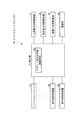
図1は、本実施の形態に係る立体物製造方法のフローチャートである。 FIG. 1 is a flowchart of the three-dimensional object manufacturing method according to the present embodiment.
図1に示すように、本実施の形態に係る立体物製造方法においては、まず、サポート材付立体物70(図2参照。)を製造するサポート材付立体物製造工程が実行される(S101)。
As shown in FIG. 1, in the three-dimensional object manufacturing method according to the present embodiment, first, a three-dimensional object manufacturing process with a support material for manufacturing a three-
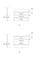
図2は、サポート材付立体物70の一例の断面図である。
FIG. 2 is a cross-sectional view of an example of the three-
図2に示すように、サポート材付立体物70は、立体物80と、立体物80を支持するサポート材90とを備えている。サポート材付立体物70は、UV硬化型インクによって形成されている。なお、UV硬化型インクは、紫外線吸収剤を含んでいて、紫外線が照射されることによって硬化するインクである。
As shown in FIG. 2, the three-
立体物80は、立体物80の表面部分を形成していて色がつけられている着色部分81と、着色部分81以外の部分を形成している非着色部分82とを備えている。立体物80は、立体物80の材料となるUV硬化型インクである造形用インクによって形成されている。特に、着色部分81は、着色するための造形用インクである造形用カラーインクによって形成されている。なお、造形用カラーインクは、顔料、染料などの色材を含んでいることによって発色するインクである。
The three-
サポート材90は、着色部分81に接触していて色がつけられている着色部分91と、着色部分91以外の部分を形成している非着色部分92とを備えている。サポート材90は、サポート材90の材料となるUV硬化型インクであるサポート用インクによって形成されている。特に、着色部分91は、着色するためのサポート用インクであるサポート用カラーインクによって形成されている。なお、サポート用インクは、アルコール類などの溶剤や、水などの特定の溶媒に容易に溶解するインクである。また、サポート用カラーインクは、顔料、染料などの色材を含んでいることによって発色する。
The
図1に示すように、本実施の形態に係る立体物製造方法においては、S101のサポート材付立体物製造工程の後、S101のサポート材付立体物製造工程によって製造されたサポート材付立体物70を例えば水や湯に浸けるなどして、サポート材付立体物70からサポート材90を除去して図3に示すように立体物80を取得する立体物取得工程が実行される(S102)。
As shown in FIG. 1, in the three-dimensional object manufacturing method according to the present embodiment, the three-dimensional object with a support material manufactured by the three-dimensional object manufacturing process with a support material in S101 after the three-dimensional object manufacturing process with a support material in S101. A three-dimensional object acquisition step is performed in which the
本実施の形態に係る立体物製造方法においては、S102の立体物取得工程の後、S102の立体物取得工程によって取得された立体物80の表面にクリアーインクを例えば手作業など、インクジェットプリンターによる印刷以外の方法で塗布するクリアーインク塗布工程が実行される(S103)。
In the three-dimensional object manufacturing method according to the present embodiment, after the three-dimensional object acquisition step of S102, printing with a clear ink is applied to the surface of the three-
次に、S101のサポート材付立体物製造工程において使用される立体物製造装置としてのインクジェットプリンター10(図4参照。)の構成について説明する。 Next, the structure of the inkjet printer 10 (refer FIG. 4) as a three-dimensional object manufacturing apparatus used in the three-dimensional object manufacturing process with support material of S101 is demonstrated.
図4は、インクジェットプリンター10の一部の概略正面図である。図5は、インクジェットプリンター10の一部の概略上面図である。
FIG. 4 is a schematic front view of a part of the
図4および図5に示すように、インクジェットプリンター10は、サポート材付立体物70を支持する台21と、矢印11で示す主走査方向、および、主走査方向に直交する矢印12で示す副走査方向に、台21に対して移動可能に支持されているキャリッジ22とを備えている。
As shown in FIG. 4 and FIG. 5, the
インクジェットプリンター10は、主走査方向および副走査方向の両方に直交する矢印13で示す鉛直方向に台21に向けてUV硬化型インク23aを吐出するためのノズル23bが並んだノズル列23cを複数列備えているインクジェットヘッド23をキャリッジ22に複数搭載している。複数のインクジェットヘッド23は、主走査方向に並んでいる。ノズル列23cは、副走査方向に延在している。
The
インクジェットヘッド23は、主走査方向に隣り合うノズル23b同士の距離や、副走査方向に隣り合うノズル23b同士の距離がインクジェットヘッド23によるUV硬化型インク23aの着弾時のドットの径より短い。
In the
インクジェットプリンター10に備えられるインクジェットヘッド23の少なくとも1つは、造形用インクを吐出する。特に、造形用インクを吐出するインクジェットヘッド23の少なくとも1つは、造形用カラーインクを吐出する。例えば、インクジェットプリンター10は、イエローの造形用カラーインクを吐出するインクジェットヘッド23と、マゼンタの造形用カラーインクを吐出するインクジェットヘッド23と、シアンの造形用カラーインクを吐出するインクジェットヘッド23とを備えている。イエローの造形用カラーインクを吐出するインクジェットヘッド23と、マゼンタの造形用カラーインクを吐出するインクジェットヘッド23と、シアンの造形用カラーインクを吐出するインクジェットヘッド23とは、主走査方向のうち矢印11aで示す方向に、この順番で並んで配置されている。
At least one of the inkjet heads 23 provided in the
インクジェットプリンター10に備えられるインクジェットヘッド23の少なくとも1つは、サポート用インクを吐出する。特に、サポート用インクを吐出するインクジェットヘッド23の少なくとも1つは、サポート用カラーインクを吐出する。例えば、インクジェットプリンター10は、イエローのサポート用カラーインクを吐出するインクジェットヘッド23と、マゼンタのサポート用カラーインクを吐出するインクジェットヘッド23と、シアンのサポート用カラーインクを吐出するインクジェットヘッド23とを備えている。イエローのサポート用カラーインクを吐出するインクジェットヘッド23と、マゼンタのサポート用カラーインクを吐出するインクジェットヘッド23と、シアンのサポート用カラーインクを吐出するインクジェットヘッド23とは、主走査方向のうち矢印11aで示す方向に、この順番で並んで配置されている。
At least one of the inkjet heads 23 provided in the
インクジェットプリンター10は、台21に向けて紫外線を照射するUV−LED(Light Emitting Diode)などの紫外線照射装置24をキャリッジ22における主走査方向の両端部に搭載している。
The
図6は、インクジェットプリンター10のブロック図である。
FIG. 6 is a block diagram of the
図6に示すように、インクジェットプリンター10は、台21に対してキャリッジ22を主走査方向に相対移動させるヘッド移動手段としての主走査方向移動装置31と、台21に対してキャリッジ22を副走査方向に相対移動させるヘッド移動手段としての副走査方向移動装置32と、キャリッジ22に対して台21を鉛直方向に相対移動させる鉛直方向移動装置33と、LAN(Local Area Network)などのネットワークを介さずに有線または無線で直接に、または、ネットワークを介して、外部の装置と通信を行う通信デバイスである通信部34と、インクジェットプリンター10全体を制御する制御部35とを備えている。
As shown in FIG. 6, the
制御部35は、例えば、CPU(Central Processing Unit)と、プログラムおよび各種のデータを予め記憶しているROM(Read Only Memory)と、CPUの作業領域として用いられるRAM(Random Access Memory)とを備えている。CPUは、ROMに記憶されているプログラムを実行するようになっている。 The control unit 35 includes, for example, a CPU (Central Processing Unit), a ROM (Read Only Memory) that stores programs and various data in advance, and a RAM (Random Access Memory) used as a work area of the CPU. ing. The CPU executes a program stored in the ROM.
制御部35は、ROMに記憶されているプログラムを実行することによって、UV硬化型インク23aによる印刷物を積層することによってサポート材付立体物70を製造するサポート材付立体物製造手段35aとして機能する。
The control unit 35 functions as a three-dimensional object manufacturing means 35a with a support material that manufactures the three-
次に、インクジェットプリンター10の動作について説明する。
Next, the operation of the
図7は、サポート材付立体物70を製造しているときのインクジェットプリンター10の一部の概略正面断面図である。
FIG. 7 is a schematic front sectional view of a part of the
図7に示すように、サポート材付立体物製造手段35aは、通信部34を介して入力された造形データに基づいてインクジェットヘッド23、紫外線照射装置24、主走査方向移動装置31、副走査方向移動装置32および鉛直方向移動装置33を駆動する。具体的には、サポート材付立体物製造手段35aは、主走査方向移動装置31によって主走査方向にキャリッジ22を移動させる。そして、サポート材付立体物製造手段35aは、主走査方向にキャリッジ22を移動させている場合に、インクジェットヘッド23によって台21に向けてUV硬化型インク23aを吐出するとともに、着弾したUV硬化型インク23aに紫外線照射装置24によって紫外線を照射する。そして、サポート材付立体物製造手段35aは、主走査方向における印刷が終わる度に、副走査方向移動装置32によって台21に対する副走査方向におけるキャリッジ22の位置を変更する。サポート材付立体物製造手段35aは、以上の処理を繰り返すことによって、鉛直方向における特定の位置の印刷を終わらせる。そして、サポート材付立体物製造手段35aは、鉛直方向における特定の位置の印刷が終わる度に、鉛直方向移動装置33によって副走査方向において台21の位置を下げる。サポート材付立体物製造手段35aは、以上の処理を繰り返して層状の印刷物を積層することによって、造形データに基づいたサポート材付立体物70をUV硬化型インク23aによって形成する。
As shown in FIG. 7, the three-dimensional object manufacturing means 35a with a support material is based on the modeling data input via the
サポート材付立体物製造手段35aは、立体物80の着色部分81を生成する場合、造形用カラーインクによって着色して着色部分81とする。また、サポート材付立体物製造手段35aは、サポート材90を生成する場合、サポート材90のうち立体物80の着色部分81に接する部分を、この着色部分81の色と同系色の色にサポート用カラーインクによって着色して着色部分91とする。
When generating the
サポート材付立体物製造手段35aは、複数の色の造形用カラーインクを重ねて特定の色を形成する場合、主走査方向移動装置31による台21に対するキャリッジ22の相対移動の移動方向における往路および復路の何れでインクジェットヘッド23に造形用カラーインクを吐出させるかによって、立体物80の着色部分81の表面からの複数の色の造形用カラーインクの重ね順を立体物80全体で揃える。
When the three-dimensional object manufacturing means 35a with a support material forms a specific color by stacking a plurality of color inks for modeling, the forward path in the moving direction of the relative movement of the
例えば、サポート材付立体物製造手段35aは、立体物80の着色部分81の表面上の一部の面を造形用カラーインクによって形成する場合、この面に直交する方向のうち、この面から立体物80の外部側への方向における、鉛直方向の成分が矢印13aで示す下向きである面80a、80b、80cに関しては、主走査方向のうち矢印11aで示す方向でインクジェットヘッド23に造形用カラーインクを吐出させることによって、図8(a)に示すように、鉛直方向における下からシアンの造形用カラーインク、マゼンタの造形用カラーインク、イエローの造形用カラーインクが重なる。すなわち、着色部分81の表面からの複数の色の造形用カラーインクの重ね順は、シアンの造形用カラーインク、マゼンタの造形用カラーインク、イエローの造形用カラーインクの順番になる。また、サポート材付立体物製造手段35aは、着色部分81の表面上の一部の面を造形用カラーインクによって形成する場合、この面に直交する方向のうち、この面から立体物80の外部側への方向における、鉛直方向の成分が矢印13bで示す上向きである面80d、80e、80fに関しては、主走査方向のうち矢印11aとは反対方向の矢印11bで示す方向でインクジェットヘッド23に造形用カラーインクを吐出させることによって、図8(b)に示すように、鉛直方向における下からイエローの造形用カラーインク、マゼンタの造形用カラーインク、シアンの造形用カラーインクが重なる。したがって、サポート材付立体物製造手段35aは、面80a、80b、80cに関しては矢印11aで示す方向でインクジェットヘッド23に造形用カラーインクを吐出させるとともに、面80d、80e、80fに関しては矢印11bで示す方向でインクジェットヘッド23に造形用カラーインクを吐出させることによって、着色部分81の表面からの複数の色の造形用カラーインクの重ね順を立体物80全体で、シアンの造形用カラーインク、マゼンタの造形用カラーインク、イエローの造形用カラーインクの順番で揃えることができる。そのため、着色部分81の表面の色は、シアン、マゼンタおよびイエローによって構成される特定の色であるが、一番外側の色であるシアンの影響を強く受けて、青味がかった色になる。
For example, in the case where a part of the surface of the
また、サポート材付立体物製造手段35aは、面80a、80b、80cに関しては矢印11bで示す方向でインクジェットヘッド23に造形用カラーインクを吐出させるとともに、面80d、80e、80fに関しては矢印11aで示す方向でインクジェットヘッド23に造形用カラーインクを吐出させても良い。この構成によって、サポート材付立体物製造手段35aは、着色部分81の表面からの複数の色の造形用カラーインクの重ね順を立体物80全体で、イエローの造形用カラーインク、マゼンタの造形用カラーインク、シアンの造形用カラーインクの順番で揃えることができる。そのため、着色部分81の表面の色は、シアン、マゼンタおよびイエローによって構成される特定の色であるが、一番外側の色であるイエローの影響を強く受けて、黄味がかった色になる。
The three-dimensional object manufacturing means 35a with support material causes the
以上においては、立体物80の着色部分81の表面の色について説明したが、サポート材90の着色部分91の表面の色についても、主走査方向における往路および復路の何れでインクジェットヘッド23にサポート用カラーインクを吐出させるかによって、サポート材90の着色部分91の色を変更することができる。
In the above, the color of the surface of the
なお、例えば図9(a)や図9(b)に示すように、サポート材90の着色部分91におけるサポート材90の表面からの複数の色のサポート用カラーインクの重ね順は、この着色部分91に接触する着色部分81における立体物80の表面からの複数の色の造形用カラーインクの重ね順と反対であっても良い。この構成によって、サポート材付立体物70からサポート材90が除去された後、立体物80の表面にサポート材90が残っていても、立体物80の表面の着色部分81と、立体物80の表面に残ったサポート材90の着色部分91とで色の重ね順が同じであるので、立体物80の表面に残ったサポート材90が更に視認され難くなる。
For example, as shown in FIGS. 9A and 9B, the order in which the color inks for supporting a plurality of colors from the surface of the
サポート材付立体物製造手段35aは、インクジェットヘッド23による造形用インクの吐出毎の主走査方向移動装置31または副走査方向移動装置32による台21に対するキャリッジ22の相対移動の移動量を、鉛直方向に対する立体物80の表面の角度に応じて変更することによって、立体物80の表面の単位面積に対する造形用インクの着弾数量を略一定化する。例えば、サポート材付立体物製造手段35aは、図10(a)に示すように、立体物80の表面のうち鉛直方向に対する角度が90°である表面を生成する場合に、インクジェットヘッド23による造形用インクの吐出毎の主走査方向移動装置31または副走査方向移動装置32による台21に対するキャリッジ22の相対移動の移動量が距離41であるとき、図10(b)に示すように、立体物80の表面のうち鉛直方向に対する角度が30°である表面を生成する場合に、インクジェットヘッド23による造形用インクの吐出毎の主走査方向移動装置31または副走査方向移動装置32による台21に対するキャリッジ22の相対移動の移動量を距離41の半分である距離42とする。これによって、サポート材付立体物製造手段35aは、立体物80の表面のうち鉛直方向に対する角度が90°である表面を生成する場合のインクジェットヘッド23による造形用インクの吐出毎の表面の延在方向における距離41と、立体物80の表面のうち鉛直方向に対する角度が30°である表面を生成する場合のインクジェットヘッド23による造形用インクの吐出毎の表面の延在方向における距離43とを等しくすることができる。すなわち、サポート材付立体物製造手段35aは、立体物80の表面の単位面積に対する造形用インクの着弾数量を略一定化する。
The three-dimensional object manufacturing means 35a with a support material determines the movement amount of the relative movement of the
以上に説明したように、本実施の形態に係る立体物製造方法は、サポート材90のうち立体物80の着色部分81に接する部分である着色部分91を、着色部分81の色と同系色の色に着色したサポート材付立体物70を製造するので、サポート材付立体物70からサポート材90を除去して立体物80を取得した場合に、立体物80の表面の着色部分81の凹凸にサポート材90が残ったとしても、このサポート材90によって立体物80の表面の着色部分81の色が白濁化して薄くなることを抑えることができる。
As described above, in the three-dimensional object manufacturing method according to the present embodiment, the
本実施の形態に係る立体物製造方法は、UV硬化型インクの吐出方向に対する立体物80の表面の角度に関わらず、立体物80の表面の単位面積に対する造形用インクの着弾数量を略一定化するので、立体物80の表面に凹凸が生じることを抑えることができる。したがって、本実施の形態に係る立体物製造方法は、サポート材付立体物70からサポート材90を除去して立体物80を取得した場合に、立体物80の表面の凹凸に残ったサポート材90によって立体物80の表面の着色部分81の色が白濁化して薄くなることや、立体物80の表面の凹凸で生じる乱反射によって立体物80の表面の着色部分81の色が白濁化して薄くなることを抑えることができる。
In the three-dimensional object manufacturing method according to the present embodiment, the landing amount of the modeling ink with respect to the unit area of the surface of the three-
本実施の形態に係る立体物製造方法は、立体物80の表面に生じた凹凸をクリアーインクで埋める(S103)ので、立体物80の表面の凹凸で生じる乱反射によって立体物80の表面の着色部分81の色が白濁化して薄くなることを抑えることができる。
In the three-dimensional object manufacturing method according to the present embodiment, the unevenness generated on the surface of the three-
インクジェットヘッド23は、上述したように、主走査方向に隣り合うノズル23b同士の距離や、副走査方向に隣り合うノズル23b同士の距離がインクジェットヘッド23によるUV硬化型インク23aの着弾時のドットの径より短い。この構成により、本実施の形態に係る立体物製造方法は、UV硬化型インク23aの着弾時にUV硬化型インク23aのドット同士を液体状態で連結させることが可能であるので、UV硬化型インク23aのドット同士を連結させることによって立体物80の表面に凹凸が生じることを抑えることができる。したがって、本実施の形態に係る立体物製造方法は、サポート材付立体物70からサポート材90を除去して立体物80を取得した場合に、立体物80の表面の凹凸に残ったサポート材90によって立体物80の表面の着色部分81の色が白濁化して薄くなることや、立体物80の表面の凹凸で生じる乱反射によって立体物80の表面の着色部分81の色が白濁化して薄くなることを抑えることができる。
As described above, the
本実施の形態に係る立体物製造方法は、立体物80の表面からの複数の色の造形用カラーインクの重ね順を立体物80全体で揃えるので、複数の色の造形用カラーインクを重ねて形成した色のブレを抑えることができる。
In the three-dimensional object manufacturing method according to the present embodiment, since the stacking order of the color inks for modeling of a plurality of colors from the surface of the three-
なお、本実施の形態に係る立体物製造方法は、造形用インクが特色の造形用カラーインクを含んでいても良い。この構成により、本実施の形態に係る立体物製造方法は、複数の色の造形用カラーインクを重ねて形成する色と同等の特色の造形用カラーインクを使用することによって、立体物80の表面からの複数の色の造形用カラーインクの重ね順の相違による色のブレの発生を抑えることができる。
In the three-dimensional object manufacturing method according to the present embodiment, the modeling ink may include a special modeling color ink. With this configuration, the method for manufacturing a three-dimensional object according to the present embodiment uses the surface color of the three-
主走査方向移動装置31は、本実施の形態において、主走査方向にキャリッジ22を移動させることによって台21に対してキャリッジ22を主走査方向に相対移動させる。しかしながら、主走査方向移動装置31は、主走査方向に台21を移動させることによって台21に対してキャリッジ22を主走査方向に相対移動させても良いし、主走査方向に台21およびキャリッジ22をそれぞれ移動させることによって台21に対してキャリッジ22を主走査方向に相対移動させても良い。
In the present embodiment, the main scanning
副走査方向移動装置32は、本実施の形態において、副走査方向にキャリッジ22を移動させることによって台21に対してキャリッジ22を副走査方向に相対移動させる。しかしながら、副走査方向移動装置32は、副走査方向に台21を移動させることによって台21に対してキャリッジ22を副走査方向に相対移動させても良いし、副走査方向に台21およびキャリッジ22をそれぞれ移動させることによって台21に対してキャリッジ22を副走査方向に相対移動させても良い。
In the present embodiment, the sub-scanning
鉛直方向移動装置33は、本実施の形態において、鉛直方向に台21を移動させることによって台21に対してキャリッジ22を鉛直方向に相対移動させる。しかしながら、鉛直方向移動装置33は、鉛直方向にキャリッジ22を移動させることによって台21に対してキャリッジ22を鉛直方向に相対移動させても良いし、鉛直方向に台21およびキャリッジ22をそれぞれ移動させることによって台21に対してキャリッジ22を鉛直方向に相対移動させても良い。
In the present embodiment, the vertical
10 インクジェットプリンター(立体物製造装置)
21 台
23 インクジェットヘッド
23a UV硬化型インク
23b ノズル
31 主走査方向移動装置(ヘッド移動手段)
32 副走査方向移動装置(ヘッド移動手段)
35a サポート材付立体物製造手段
70 サポート材付立体物
80 立体物
81 着色部分
90 サポート材
91 着色部分(サポート材のうち立体物の着色部分に接する部分)
10 Inkjet printer (three-dimensional object manufacturing equipment)
21
32 Sub-scanning direction moving device (head moving means)
35a Three-dimensional object manufacturing means with
Claims (7)
前記サポート材付立体物製造工程によって製造された前記サポート材付立体物から前記サポート材を除去して前記立体物を取得する立体物取得工程と
を備えており、
前記インクは、
前記立体物の材料となる造形用インクと、
前記サポート材の材料となるサポート用インクと
を含んでおり、
前記造形用インクは、前記立体物の少なくとも一部を着色するための造形用カラーインクを含んでおり、
前記サポート用インクは、前記サポート材の少なくとも一部を着色するためのサポート用カラーインクを含んでおり、
前記サポート材付立体物製造工程は、前記立体物のうち前記造形用カラーインクによる着色部分を生成する場合、前記サポート材のうち前記着色部分に接する部分を、この着色部分の色と同系色の色に前記サポート用カラーインクによって着色する工程であることを特徴とする立体物製造方法。 A three-dimensional object manufacturing process with a support material for manufacturing a three-dimensional object with a support material on which the three-dimensional object is supported on a support material that supports the three-dimensional object;
A three-dimensional object acquisition step of obtaining the three-dimensional object by removing the support material from the three-dimensional object with the support material manufactured by the three-dimensional object manufacturing process with the support material, and
The ink is
Modeling ink to be the material of the three-dimensional object;
A support ink as a material of the support material,
The modeling ink includes a modeling color ink for coloring at least a part of the three-dimensional object,
The support ink includes a support color ink for coloring at least a part of the support material;
In the three-dimensional object manufacturing process with a support material, when generating a colored portion with the modeling color ink in the three-dimensional object, a portion of the support material that is in contact with the colored portion has a color similar to the color of the colored portion. A method for producing a three-dimensional object, characterized in that it is a step of coloring a color with the color ink for support.
前記インクジェットプリンターは、
前記サポート材付立体物を支持するための台と、
前記台に向けて前記インクを吐出するインクジェットヘッドと、
前記インクジェットヘッドによる前記インクの吐出方向とは直交する方向に前記インクジェットヘッドを前記台に対して相対移動させるヘッド移動手段と
を備えており、
前記サポート材付立体物製造工程は、前記インクジェットヘッドによる前記造形用インクの吐出毎の前記ヘッド移動手段による前記台に対する前記インクジェットヘッドの相対移動の移動量を、前記吐出方向に対する前記立体物の表面の角度に応じて変更することによって、前記立体物の表面の単位面積に対する前記造形用インクの着弾数量を略一定化する工程であることを特徴とする請求項1に記載の立体物製造方法。 The three-dimensional object manufacturing process with a support material is a process of manufacturing the printed matter by an inkjet printer,
The inkjet printer is
A stand for supporting the three-dimensional object with the support material;
An inkjet head that ejects the ink toward the table;
A head moving means for moving the inkjet head relative to the table in a direction orthogonal to a direction in which the ink is ejected by the inkjet head;
The three-dimensional object manufacturing step with the support material includes: a moving amount of the relative movement of the inkjet head with respect to the table by the head moving means for each ejection of the modeling ink by the inkjet head, and a surface of the three-dimensional object with respect to the ejection direction. The method for manufacturing a three-dimensional object according to claim 1, wherein the method is a step of making the landing quantity of the modeling ink substantially constant with respect to a unit area of the surface of the three-dimensional object by changing the angle according to the angle.
前記インクジェットプリンターは、
前記サポート材付立体物を支持するための台と、
前記台に向けて前記インクを吐出する複数のノズルを備えているインクジェットヘッドと
を備えており、
隣り合う前記ノズル同士の距離は、前記インクジェットヘッドによる前記インクの着弾時のドットの径より短いことを特徴とする請求項1に記載の立体物製造方法。 The three-dimensional object manufacturing process with a support material is a process of manufacturing the printed matter by an inkjet printer,
The inkjet printer is
A stand for supporting the three-dimensional object with the support material;
An inkjet head having a plurality of nozzles that eject the ink toward the table;
The three-dimensional object manufacturing method according to claim 1, wherein a distance between the adjacent nozzles is shorter than a diameter of a dot when the ink is landed by the inkjet head.
前記サポート材付立体物製造工程は、インクジェットプリンターによって前記印刷物を製造する工程であり、
前記インクジェットプリンターは、
前記サポート材付立体物を支持するための台と、
前記台に向けて前記インクを吐出するインクジェットヘッドと、
前記インクジェットヘッドによる前記インクの吐出方向とは直交する方向であって、複数の色の前記造形用カラーインクのそれぞれの前記インクジェットヘッドが並んでいる方向に、前記インクジェットヘッドを前記台に対して相対移動させるヘッド移動手段と
を備えており、
前記サポート材付立体物製造工程は、複数の色の前記造形用カラーインクを重ねて特定の色を形成する場合、前記ヘッド移動手段による前記台に対する前記インクジェットヘッドの相対移動の移動方向における往路および復路の何れで前記インクジェットヘッドに前記造形用カラーインクを吐出させるかによって、前記立体物の表面からの複数の色の前記造形用カラーインクの重ね順を前記立体物全体で揃える工程であることを特徴とする請求項1に記載の立体物製造方法。 The modeling ink includes a plurality of modeling color inks,
The three-dimensional object manufacturing process with a support material is a process of manufacturing the printed matter by an inkjet printer,
The inkjet printer is
A stand for supporting the three-dimensional object with the support material;
An inkjet head that ejects the ink toward the table;
The inkjet head is relative to the platform in a direction orthogonal to the ink ejection direction of the inkjet head and in a direction in which the inkjet heads of the color inks for modeling of a plurality of colors are arranged. And a head moving means for moving,
In the three-dimensional object manufacturing process with a support material, when a specific color is formed by superimposing a plurality of color inks for modeling, a forward path in a moving direction of the relative movement of the inkjet head with respect to the table by the head moving means and It is a step of aligning the stacking order of the color inks for modeling of a plurality of colors from the surface of the three-dimensional object in the entire three-dimensional object, depending on whether the ink-jet head is caused to eject the color ink for modeling on the return path. The three-dimensional object manufacturing method according to claim 1, wherein
前記インクは、
前記立体物の材料となる造形用インクと、
前記サポート材の材料となるサポート用インクと
を含んでおり、
前記造形用インクは、前記立体物の少なくとも一部を着色するための造形用カラーインクを含んでおり、
前記サポート用インクは、前記サポート材の少なくとも一部を着色するためのサポート用カラーインクを含んでおり、
前記サポート材付立体物製造手段は、前記立体物のうち前記造形用カラーインクによる着色部分を生成する場合、前記サポート材のうち前記着色部分に接する部分を、この着色部分の色と同系色の色に前記サポート用カラーインクによって着色する手段であることを特徴とする立体物製造装置。 A support material with a support material for producing a solid material with a support material on which the solid material is supported by laminating a printed material with ink on the support material supporting the three-dimensional object;
The ink is
Modeling ink to be the material of the three-dimensional object;
A support ink as a material of the support material,
The modeling ink includes a modeling color ink for coloring at least a part of the three-dimensional object,
The support ink includes a support color ink for coloring at least a part of the support material;
When the three-dimensional object manufacturing means with the support material generates a colored portion by the modeling color ink in the three-dimensional object, a portion of the support material that is in contact with the colored portion has a color similar to the color of the colored portion. A three-dimensional object manufacturing apparatus, characterized in that it is means for coloring a color with the color ink for support.
Priority Applications (1)
| Application Number | Priority Date | Filing Date | Title |
|---|---|---|---|
| JP2016134694A JP2018001686A (en) | 2016-07-07 | 2016-07-07 | Solid body production method and solid body production device |
Applications Claiming Priority (1)
| Application Number | Priority Date | Filing Date | Title |
|---|---|---|---|
| JP2016134694A JP2018001686A (en) | 2016-07-07 | 2016-07-07 | Solid body production method and solid body production device |
Publications (2)
| Publication Number | Publication Date |
|---|---|
| JP2018001686A true JP2018001686A (en) | 2018-01-11 |
| JP2018001686A5 JP2018001686A5 (en) | 2019-01-24 |
Family
ID=60945737
Family Applications (1)
| Application Number | Title | Priority Date | Filing Date |
|---|---|---|---|
| JP2016134694A Pending JP2018001686A (en) | 2016-07-07 | 2016-07-07 | Solid body production method and solid body production device |
Country Status (1)
| Country | Link |
|---|---|
| JP (1) | JP2018001686A (en) |
Cited By (2)
| Publication number | Priority date | Publication date | Assignee | Title |
|---|---|---|---|---|
| EP3539774A1 (en) * | 2018-03-13 | 2019-09-18 | Ricoh Company, Ltd. | Three-dimensional fabricating apparatus and three-dimensional fabricating method |
| JP2020151958A (en) * | 2019-03-20 | 2020-09-24 | 株式会社リコー | Apparatus of manufacturing three-dimensional modeled product, method of manufacturing three-dimensional modeled product, and three-dimensional molding program |
Citations (6)
| Publication number | Priority date | Publication date | Assignee | Title |
|---|---|---|---|---|
| JP2001239652A (en) * | 2000-02-28 | 2001-09-04 | Minolta Co Ltd | Printer and printing method |
| JP2005297229A (en) * | 2004-04-07 | 2005-10-27 | Mimaki Engineering Co Ltd | Inkjet printer for button fabrication and button fabrication method using it |
| JP2014128901A (en) * | 2012-12-28 | 2014-07-10 | Canon Inc | Image processing device and image processing method |
| JP2014136311A (en) * | 2013-01-15 | 2014-07-28 | Konica Minolta Inc | Device for molding three-dimensional object, and method for molding three-dimensional object |
| JP2015123687A (en) * | 2013-12-26 | 2015-07-06 | 株式会社ミマキエンジニアリング | Method for producing molding and control device |
| JP2016047603A (en) * | 2014-08-27 | 2016-04-07 | 株式会社ミマキエンジニアリング | Three-dimensional article molding apparatus and method for manufacturing three-dimensional article |
-
2016
- 2016-07-07 JP JP2016134694A patent/JP2018001686A/en active Pending
Patent Citations (6)
| Publication number | Priority date | Publication date | Assignee | Title |
|---|---|---|---|---|
| JP2001239652A (en) * | 2000-02-28 | 2001-09-04 | Minolta Co Ltd | Printer and printing method |
| JP2005297229A (en) * | 2004-04-07 | 2005-10-27 | Mimaki Engineering Co Ltd | Inkjet printer for button fabrication and button fabrication method using it |
| JP2014128901A (en) * | 2012-12-28 | 2014-07-10 | Canon Inc | Image processing device and image processing method |
| JP2014136311A (en) * | 2013-01-15 | 2014-07-28 | Konica Minolta Inc | Device for molding three-dimensional object, and method for molding three-dimensional object |
| JP2015123687A (en) * | 2013-12-26 | 2015-07-06 | 株式会社ミマキエンジニアリング | Method for producing molding and control device |
| JP2016047603A (en) * | 2014-08-27 | 2016-04-07 | 株式会社ミマキエンジニアリング | Three-dimensional article molding apparatus and method for manufacturing three-dimensional article |
Cited By (5)
| Publication number | Priority date | Publication date | Assignee | Title |
|---|---|---|---|---|
| EP3539774A1 (en) * | 2018-03-13 | 2019-09-18 | Ricoh Company, Ltd. | Three-dimensional fabricating apparatus and three-dimensional fabricating method |
| JP2019155714A (en) * | 2018-03-13 | 2019-09-19 | 株式会社リコー | Three-dimensional molding apparatus and three-dimensional molding method |
| JP7087482B2 (en) | 2018-03-13 | 2022-06-21 | 株式会社リコー | Three-dimensional modeling device and three-dimensional modeling method |
| US11390022B2 (en) | 2018-03-13 | 2022-07-19 | Ricoh Company, Ltd. | Three-dimensional fabricating apparatus and three-dimensional fabricating method |
| JP2020151958A (en) * | 2019-03-20 | 2020-09-24 | 株式会社リコー | Apparatus of manufacturing three-dimensional modeled product, method of manufacturing three-dimensional modeled product, and three-dimensional molding program |
Similar Documents
| Publication | Publication Date | Title |
|---|---|---|
| JP6590473B2 (en) | Three-dimensional object forming apparatus and three-dimensional object forming method | |
| JP6434727B2 (en) | Three-dimensional object forming method and three-dimensional object forming apparatus | |
| JP6532286B2 (en) | Three-dimensional object formation apparatus and three-dimensional object formation method | |
| JP6426022B2 (en) | Liquid discharge apparatus and liquid discharge method | |
| JP6396723B2 (en) | Droplet discharge apparatus and droplet discharge method | |
| WO2016167239A1 (en) | Three-dimensional object modeling method and 3d printer | |
| EP3433072B1 (en) | Indexing in 3d printing | |
| JP2016064539A (en) | Three-dimensional molding apparatus and three-dimensional molding method | |
| JP6550280B2 (en) | Forming apparatus and forming method | |
| JP6278704B2 (en) | Manufacturing method of printed matter | |
| US20180022021A1 (en) | Three-dimensional object shaping method and three-dimensional object shaping device | |
| JP6861053B2 (en) | Modeling equipment and modeling method | |
| JP6533493B2 (en) | Forming apparatus and forming method | |
| JP2016172412A5 (en) | ||
| JP2018001686A (en) | Solid body production method and solid body production device | |
| JP2016147457A (en) | Three-dimensional molding apparatus and three-dimensional molding method | |
| JP2013119244A (en) | Method for printing stereoscopic pattern by digital control system uv ink jet | |
| JP6434817B2 (en) | Printing apparatus and printing method | |
| JP2014168851A (en) | Printer and printing method | |
| JP6550281B2 (en) | Forming apparatus and forming method | |
| JP2020147046A (en) | Shaping device | |
| WO2017002926A1 (en) | Molding device and molding method | |
| JP7210187B2 (en) | LIQUID EJECTING APPARATUS AND LIQUID EJECTING METHOD | |
| JP2018001686A5 (en) | ||
| US20120268538A1 (en) | Printing apparatus, printing method, and program |
Legal Events
| Date | Code | Title | Description |
|---|---|---|---|
| A621 | Written request for application examination |
Free format text: JAPANESE INTERMEDIATE CODE: A621 Effective date: 20181004 |
|
| A521 | Request for written amendment filed |
Free format text: JAPANESE INTERMEDIATE CODE: A523 Effective date: 20181005 |
|
| A521 | Request for written amendment filed |
Free format text: JAPANESE INTERMEDIATE CODE: A523 Effective date: 20181206 |
|
| A977 | Report on retrieval |
Free format text: JAPANESE INTERMEDIATE CODE: A971007 Effective date: 20190813 |
|
| A131 | Notification of reasons for refusal |
Free format text: JAPANESE INTERMEDIATE CODE: A131 Effective date: 20190918 |
|
| A601 | Written request for extension of time |
Free format text: JAPANESE INTERMEDIATE CODE: A601 Effective date: 20191114 |
|
| A02 | Decision of refusal |
Free format text: JAPANESE INTERMEDIATE CODE: A02 Effective date: 20200318 |