JP2017537864A - Tools for glass bending process - Google Patents
Tools for glass bending process Download PDFInfo
- Publication number
- JP2017537864A JP2017537864A JP2017523224A JP2017523224A JP2017537864A JP 2017537864 A JP2017537864 A JP 2017537864A JP 2017523224 A JP2017523224 A JP 2017523224A JP 2017523224 A JP2017523224 A JP 2017523224A JP 2017537864 A JP2017537864 A JP 2017537864A
- Authority
- JP
- Japan
- Prior art keywords
- tool
- pressure
- glass plate
- bending
- contact surface
- Prior art date
- Legal status (The legal status is an assumption and is not a legal conclusion. Google has not performed a legal analysis and makes no representation as to the accuracy of the status listed.)
- Granted
Links
Images


Classifications
-
- C—CHEMISTRY; METALLURGY
- C03—GLASS; MINERAL OR SLAG WOOL
- C03B—MANUFACTURE, SHAPING, OR SUPPLEMENTARY PROCESSES
- C03B23/00—Re-forming shaped glass
- C03B23/02—Re-forming glass sheets
- C03B23/023—Re-forming glass sheets by bending
- C03B23/03—Re-forming glass sheets by bending by press-bending between shaping moulds
- C03B23/0305—Press-bending accelerated by applying mechanical forces, e.g. inertia, weights or local forces
-
- C—CHEMISTRY; METALLURGY
- C03—GLASS; MINERAL OR SLAG WOOL
- C03B—MANUFACTURE, SHAPING, OR SUPPLEMENTARY PROCESSES
- C03B23/00—Re-forming shaped glass
- C03B23/02—Re-forming glass sheets
- C03B23/023—Re-forming glass sheets by bending
- C03B23/035—Re-forming glass sheets by bending using a gas cushion or by changing gas pressure, e.g. by applying vacuum or blowing for supporting the glass while bending
-
- C—CHEMISTRY; METALLURGY
- C03—GLASS; MINERAL OR SLAG WOOL
- C03B—MANUFACTURE, SHAPING, OR SUPPLEMENTARY PROCESSES
- C03B35/00—Transporting of glass products during their manufacture, e.g. hot glass lenses, prisms
- C03B35/14—Transporting hot glass sheets or ribbons, e.g. by heat-resistant conveyor belts or bands
- C03B35/145—Transporting hot glass sheets or ribbons, e.g. by heat-resistant conveyor belts or bands by top-side transfer or supporting devices, e.g. lifting or conveying using suction
-
- C—CHEMISTRY; METALLURGY
- C03—GLASS; MINERAL OR SLAG WOOL
- C03B—MANUFACTURE, SHAPING, OR SUPPLEMENTARY PROCESSES
- C03B23/00—Re-forming shaped glass
- C03B23/02—Re-forming glass sheets
- C03B23/023—Re-forming glass sheets by bending
- C03B23/025—Re-forming glass sheets by bending by gravity
-
- C—CHEMISTRY; METALLURGY
- C03—GLASS; MINERAL OR SLAG WOOL
- C03B—MANUFACTURE, SHAPING, OR SUPPLEMENTARY PROCESSES
- C03B23/00—Re-forming shaped glass
- C03B23/02—Re-forming glass sheets
- C03B23/023—Re-forming glass sheets by bending
- C03B23/025—Re-forming glass sheets by bending by gravity
- C03B23/0252—Re-forming glass sheets by bending by gravity by gravity only, e.g. sagging
-
- C—CHEMISTRY; METALLURGY
- C03—GLASS; MINERAL OR SLAG WOOL
- C03B—MANUFACTURE, SHAPING, OR SUPPLEMENTARY PROCESSES
- C03B23/00—Re-forming shaped glass
- C03B23/02—Re-forming glass sheets
- C03B23/023—Re-forming glass sheets by bending
- C03B23/03—Re-forming glass sheets by bending by press-bending between shaping moulds
- C03B23/0302—Re-forming glass sheets by bending by press-bending between shaping moulds between opposing full-face shaping moulds
-
- C—CHEMISTRY; METALLURGY
- C03—GLASS; MINERAL OR SLAG WOOL
- C03B—MANUFACTURE, SHAPING, OR SUPPLEMENTARY PROCESSES
- C03B23/00—Re-forming shaped glass
- C03B23/02—Re-forming glass sheets
- C03B23/023—Re-forming glass sheets by bending
- C03B23/035—Re-forming glass sheets by bending using a gas cushion or by changing gas pressure, e.g. by applying vacuum or blowing for supporting the glass while bending
- C03B23/0352—Re-forming glass sheets by bending using a gas cushion or by changing gas pressure, e.g. by applying vacuum or blowing for supporting the glass while bending by suction or blowing out for providing the deformation force to bend the glass sheet
- C03B23/0357—Re-forming glass sheets by bending using a gas cushion or by changing gas pressure, e.g. by applying vacuum or blowing for supporting the glass while bending by suction or blowing out for providing the deformation force to bend the glass sheet by suction without blowing, e.g. with vacuum or by venturi effect
-
- C—CHEMISTRY; METALLURGY
- C03—GLASS; MINERAL OR SLAG WOOL
- C03B—MANUFACTURE, SHAPING, OR SUPPLEMENTARY PROCESSES
- C03B35/00—Transporting of glass products during their manufacture, e.g. hot glass lenses, prisms
- C03B35/14—Transporting hot glass sheets or ribbons, e.g. by heat-resistant conveyor belts or bands
-
- Y—GENERAL TAGGING OF NEW TECHNOLOGICAL DEVELOPMENTS; GENERAL TAGGING OF CROSS-SECTIONAL TECHNOLOGIES SPANNING OVER SEVERAL SECTIONS OF THE IPC; TECHNICAL SUBJECTS COVERED BY FORMER USPC CROSS-REFERENCE ART COLLECTIONS [XRACs] AND DIGESTS
- Y02—TECHNOLOGIES OR APPLICATIONS FOR MITIGATION OR ADAPTATION AGAINST CLIMATE CHANGE
- Y02P—CLIMATE CHANGE MITIGATION TECHNOLOGIES IN THE PRODUCTION OR PROCESSING OF GOODS
- Y02P40/00—Technologies relating to the processing of minerals
- Y02P40/50—Glass production, e.g. reusing waste heat during processing or shaping
Landscapes
- Chemical & Material Sciences (AREA)
- Engineering & Computer Science (AREA)
- Materials Engineering (AREA)
- Organic Chemistry (AREA)
- Re-Forming, After-Treatment, Cutting And Transporting Of Glass Products (AREA)
- Grinding And Polishing Of Tertiary Curved Surfaces And Surfaces With Complex Shapes (AREA)
- Measuring Fluid Pressure (AREA)
Abstract
本発明は、曲げプロセスにおいて吸引作用により少なくとも1つのガラス板(I,II)を保持する工具(1)であって、枠状の凸の接触面(2)と、接触面(2)を少なくとも部分的に包囲する周囲の空気案内板(4)を有するカバー(3)とを備え、空気案内板(4)と接触面(2)との間の第1の圧力領域(B1)に、減じられた第1の圧力(p1)を発生させ、接触面(2)より内側の中央領域に配置されている第2の圧力領域(B2)に、第1の圧力(p1)より大きい第2の圧力(p2)を発生させるに好適な工具(1)に関する。The present invention provides a tool (1) for holding at least one glass plate (I, II) by suction in a bending process, wherein a frame-shaped convex contact surface (2) and a contact surface (2) are at least A cover (3) having a surrounding air guide plate (4) partially surrounding, and reduced to a first pressure region (B1) between the air guide plate (4) and the contact surface (2) The first pressure (p1) generated is generated, and the second pressure region (B2) disposed in the central region inside the contact surface (2) has a second pressure greater than the first pressure (p1). The present invention relates to a tool (1) suitable for generating a pressure (p2).
Description
本発明は、ガラス曲げプロセス用の工具、ガラス板を曲げる方法及び工具の使用に関する。 The present invention relates to a tool for a glass bending process, a method of bending a glass plate and the use of the tool.
車両分野では、曲げられた合わせガラス(Verbundglas)が、特にウインドシールドとして、一般的である。合わせガラスの個々の板をまとめて同時に曲げると有利なことが知られている。ペア状に曲げたガラス板は、その曲げに関して互いに適合されており、それゆえ、互いに積層して合わせガラスとするに特に好適である。ガラス板をペア状に曲げる方法は、例えば独国特許出願公開第10105200号明細書(DE 101 05 200 A1)において公知である。
In the vehicle field, bent laminated glass (Verbundglass) is common, especially as a windshield. It is known that it is advantageous to bend individual sheets of laminated glass together and bend simultaneously. Glass plates bent in pairs are adapted to each other with respect to their bending and are therefore particularly suitable for being laminated together to form laminated glass. A method for bending glass plates in pairs is known, for example, in
欧州特許第1836136号明細書(EP 1 836 136 B1)は、別の曲げ方法と、当該刊行物において上側の型(forme superieure(superieureの4文字目のeは、上に「アクセント記号」あり。以下同様))と称される、本発明の前提となる工具とを開示している。凸の工具は、上側の型として曲げ方法で使用され、曲げたいガラス板を重力の影響に抗して保持するに好適である。保持工具は、枠状の凸の接触面と、周囲の空気案内板を有するカバーとを備える。板のエッジに沿った吸引作用により、曲げたいガラス板は、重力の作用に抗して接触面に圧着され、これにより、確実に工具に保持される。積み重なった2つのガラス板も、同時に工具に保持され得る。工具は、ガラス板を曲げ装置の異なる位置間で搬送するために使用され、例えばガラス板を曲げ型から受け取り、他に引き渡すために使用され得る。工具は、プレス曲げステップにも使用可能であり、プレス曲げステップの場合、ガラス板は、工具と、相補的な相手側の型との間で、圧力作用及び/又は吸引作用を働かせることで成形される。
EP 1836136 (
欧州特許第1836136号明細書(EP 1 836 136 B1)に記載の方法では、ガラス板は、第1の下側の曲げ型上で重力曲げにより予備曲げされる。その後、ガラス板は、本発明の前提となる保持工具により第1の下側の曲げ型からピックアップされ、第2の下側の曲げ型に搬送される。保持工具と、第2の下側の曲げ型との間で、ガラス板は、プレス曲げステップで最終的な形状を得て、その後、再び、本発明の前提となる保持工具により冷却のために下側の型に引き渡される。
In the method described in EP 1836136 (
米国特許第3778244号明細書(US 3,778,244 A)は、凹又は凸の全面的な接触面を備える上側の曲げ工具(フルモールド)と、周囲の空気案内板を有するカバーとを開示している。空気案内板により、曲げたいガラス板のエッジに空気流を沿わせることができ、その結果、ガラス板は、接触面に押し付けられる。付加的にガラス板は、全面的な接触面に設けられた開口を通して接触面に吸引され得る。工具及び吸引作用は、ガラス板を工具に保持するために設けられているのではなく、ガラス板の能動的な変形を達成すべきものである。 U.S. Pat. No. 3,778,244 (US 3,778,244 A) discloses an upper bending tool (full mold) with a concave or convex full contact surface and a cover with a surrounding air guide plate. The air guide plate allows an air flow to follow the edge of the glass plate to be bent, so that the glass plate is pressed against the contact surface. In addition, the glass plate can be sucked into the contact surface through an opening provided in the entire contact surface. The tool and suction action are not provided to hold the glass plate to the tool, but should achieve an active deformation of the glass plate.
今日の車両グレージングは、部分的に極めて顕著な曲率半径を有するますます複雑な形状を呈している。ガラス板を凸の保持工具によりピックアップしたとき、吸引作用が板に及ぼされ、ガラス板の曲率方向とは逆方向に作用する。それゆえ、形成した曲率が、ガラス板の保持時の吸引作用の結果として減じられてしまうおそれがある。それゆえ、この欠点を克服し、特に強く曲げた板を高品質にかつ方法技術的に有意に形成し得る新しい曲げ工具が、希求されている。 Today's vehicle glazing presents an increasingly complex shape with a partly very pronounced radius of curvature. When the glass plate is picked up by a convex holding tool, a suction action is exerted on the plate, acting in the direction opposite to the curvature direction of the glass plate. Therefore, the formed curvature may be reduced as a result of the suction action when holding the glass plate. Therefore, there is a need for new bending tools that overcome this drawback and that can form particularly strongly bent plates of high quality and methodically significantly.
本発明の根底にある課題は、このような改良した曲げ工具を提供することである。曲げ工具は、特に、板の曲げを吸引作用により減じてしまうことなく、ガラス板を重力の作用に抗して保持するに好適であることが望まれる。 The problem underlying the present invention is to provide such an improved bending tool. The bending tool is particularly desired to be suitable for holding the glass plate against the action of gravity without reducing the bending of the plate by the suction action.
本発明の課題は、本発明により、請求項1に記載の工具によって解決される。有利な構成は、従属請求項に看取可能である。
The object of the invention is solved according to the invention by a tool according to
本発明に係る、曲げプロセスにおいて吸引作用により少なくとも1つのガラス板を保持する工具は、枠状の凸の接触面と、接触面を少なくとも部分的に包囲する周囲の空気案内板を有するカバーとを備え、工具は、
−空気案内板と接触面との間の第1の圧力領域に、減じられた第1の圧力p1(保持圧)を発生させ、
−第2の圧力領域に、第1の圧力p1より大きい第2の圧力p2(補償圧)を発生させる、
に好適である。
A tool for holding at least one glass plate by suction in a bending process according to the present invention comprises a frame-like convex contact surface and a cover having a surrounding air guide plate that at least partially surrounds the contact surface. The tool is
Generating a reduced first pressure p 1 (holding pressure) in a first pressure region between the air guide plate and the contact surface;
A second pressure p 2 (compensation pressure) greater than the first pressure p 1 is generated in the second pressure region,
It is suitable for.
ここに記載した圧力p1及びp2は、特に、保持したいガラス板の、工具に対面した表面に作用する。 The pressures p 1 and p 2 described here act in particular on the surface of the glass plate to be held facing the tool.
追ってより詳細に説明するように、ガラス板は、第1の圧力領域により確実に曲げ工具に保持され、このとき、吸引作用は、特に板のエッジに作用する。第2の圧力領域には、より低い吸引作用が存在するか、又は吸引作用が全く存在せず、その結果、板形状、特に板の中央領域における板形状に対する不都合な影響は、回避できる。これは、本発明の大きな利点である。 As will be explained in more detail later, the glass plate is securely held by the bending tool by means of the first pressure region, at which time the suction action acts in particular on the edge of the plate. In the second pressure region, there is a lower suction action or no suction action at all, so that adverse effects on the plate shape, in particular the plate shape in the central region of the plate, can be avoided. This is a great advantage of the present invention.
本発明に係る工具は、吸引作用により少なくとも1つのガラス板を保持する工具群に属する。本発明に係る工具は、曲げプロセス中、負圧により発生された吸引作用が、ガラス板に及ぼされ、曲げ工具により規定通り分配され、その結果、ガラス板が吸引作用の結果として工具に圧着されることで、曲げたいガラス板の、重力の影響に抗した保持を可能とする。工具は、吸引型と称してもよい。 The tool according to the present invention belongs to a tool group that holds at least one glass plate by a suction action. In the tool according to the invention, during the bending process, the suction action generated by the negative pressure is exerted on the glass plate and distributed as prescribed by the bending tool, so that the glass plate is pressed against the tool as a result of the suction action. This makes it possible to hold the glass plate to be bent against the influence of gravity. The tool may be referred to as a suction type.
吸引作用により少なくとも1つのガラス板を保持する本発明に係る工具は、枠状の接触面を備える。つまり、ガラス板が型の面に全面的に接触する「フルサーフェスの工具(vollflaechiges Werkzeug)」ではない。むしろ、ガラス板の周囲の領域においてサイドエッジで又はサイドエッジ近傍で工具と直接接触する一方、板の大部分は、工具と直接接触しない工具群に属する。このような工具は、リング(保持リング、曲げリング)又は枠(枠型)と称されることもある。本発明の意味での「枠状の接触面」なる概念は、本発明に係る工具をフルサーフェスの型と区別するためだけのものである。接触面は、完全な枠を形成している必要はなく、中断があってもよい。接触面は、完全な又は中断された枠の形態で形成されている。 The tool according to the present invention for holding at least one glass plate by suction action includes a frame-like contact surface. That is, it is not a “full surface tool” in which the glass plate is in full contact with the mold surface. Rather, most of the plate belongs to a group of tools that are not in direct contact with the tool, while in direct contact with the tool at or near the side edge in the region around the glass plate. Such a tool may be referred to as a ring (holding ring, bending ring) or a frame (frame type). The concept of “frame-shaped contact surface” in the sense of the present invention is only for distinguishing the tool according to the present invention from a full surface mold. The contact surface need not form a complete frame and may be interrupted. The contact surface is formed in the form of a complete or interrupted frame.
接触面の幅は、好ましくは0.1cm乃至10cm、特に好ましくは0.2cm乃至1cm、例えば0.3cmである。 The width of the contact surface is preferably 0.1 cm to 10 cm, particularly preferably 0.2 cm to 1 cm, for example 0.3 cm.
さらに工具は、「スケルトン(Skelett)」を備えて構成されている。スケルトンとは、接触面を担持する面状の構造と解される。スケルトンは、接触面を有して形成されている。接触面は、スケルトンに配置されている。 Furthermore, the tool is configured with a “skeleton”. A skeleton is understood as a planar structure carrying a contact surface. The skeleton has a contact surface. The contact surface is arranged on the skeleton.
本発明に係る工具は、「凸の工具(konvexes Werkzeug)」である。これは、接触面が凸に形成されていることを意味している。ここで、凸の形状とは、ガラス板の角隅部及び縁部が、工具との規定通りの接触時、工具に向かって板の中心部より近く曲げられている形状と解される。 The tool according to the present invention is a “convex tool”. This means that the contact surface is formed to be convex. Here, the convex shape is understood as a shape in which the corners and edges of the glass plate are bent closer to the tool than the center of the plate when contacted with the tool as specified.
さらに本発明に係る工具は、カバーを備える。カバーは、接触面の、保持プロセス又は曲げプロセス中にガラス板から背離した側に配置されている。カバーは、保持プロセスにとって重要な吸引作用を発生させる。吸引作用は、特にカバーと曲げスケルトンとの間の空気を吸い出すことで発生される。 Furthermore, the tool according to the present invention includes a cover. The cover is arranged on the side of the contact surface that is away from the glass plate during the holding or bending process. The cover generates a suction action which is important for the holding process. The suction action is generated in particular by sucking air between the cover and the bending skeleton.
カバーは、接触面を少なくとも部分的に包囲する周囲の空気案内板を有して形成されている。このような空気案内板は、しばしば、スカート(Schuerze)とも称される。空気案内板は、好ましくはカバーの端部に配置されている。空気案内板は、接触面を完全に又は部分的に包囲又は囲繞する。保持プロセス中、空気案内板は、好ましくはガラス板のサイドエッジに対して3mm乃至50mm、特に好ましくは5mm乃至30mm、例えば20mmの間隔を置いている。 The cover is formed with a surrounding air guide plate that at least partially surrounds the contact surface. Such an air guide plate is often also referred to as a skirt. The air guide plate is preferably arranged at the end of the cover. The air guide plate completely or partially surrounds or surrounds the contact surface. During the holding process, the air guide plate is preferably spaced from 3 mm to 50 mm, particularly preferably from 5 mm to 30 mm, for example 20 mm, with respect to the side edges of the glass plate.
本発明に係る曲げ工具は、少なくとも1つの第1の圧力領域に、減じられた第1の圧力p1を発生させるに好適である。減じられた圧力とは、本発明の意味で、周囲圧より低い圧力と解される。つまり、減じられた圧力とは、周囲圧に対する負圧である。減じられた圧力により吸引作用が達成される。第1の圧力p1が作用する領域は、本発明の意味で第1の圧力領域と称される。第1の圧力領域は、空気案内板と接触面との間に配置されている。第1の圧力領域は、好ましくは、単一の連続した枠状の領域である。しかし、第1の圧力領域は、互いに分割され、同じ圧力を有する複数の区域からなっていてもよい。 The bending tool according to the present invention is suitable for generating a reduced first pressure p 1 in at least one first pressure region. Reduced pressure is understood in the sense of the present invention as lower than ambient pressure. That is, the reduced pressure is a negative pressure with respect to the ambient pressure. A suction action is achieved by the reduced pressure. The region where the first pressure p 1 acts is referred to as the first pressure region in the sense of the present invention. The first pressure region is disposed between the air guide plate and the contact surface. The first pressure region is preferably a single continuous frame region. However, the first pressure region may be composed of a plurality of areas that are divided from each other and have the same pressure.
第1の圧力領域は、保持したいガラス板のエッジに沿って少なくとも部分的に空気流を発生させ、これによりガラス板を接触面に押し付けるに好適である。第1の圧力p1により発生された空気流は、空気案内板により、ガラス板のサイドエッジに少なくとも部分的に沿うように変向される。空気流によりガラス板は、効果的に曲げ工具に保持され、接触面に押し付けられる。これにより曲げ工具は、特に上側の型として曲げプロセスで使用されることができ、ガラス板は、エッジに沿った空気流により重力の作用に抗して工具に保持される。第1の圧力p1は、保持圧と称してもよい。 The first pressure region is suitable for generating an air flow at least partly along the edge of the glass plate to be held, thereby pressing the glass plate against the contact surface. The air flow generated by the first pressure p 1 is redirected by the air guide plate so as to be at least partially along the side edge of the glass plate. The glass plate is effectively held by the bending tool and pressed against the contact surface by the air flow. This allows the bending tool to be used in the bending process, in particular as an upper mold, and the glass plate is held on the tool against the action of gravity by the air flow along the edge. First pressure p 1 may be referred to as holding pressure.
上側の型とは、ガラス板の、地面から背離した上側の表面と接触する型と解される。下側の曲げ型とは、ガラス板の、地面に対面した下側の表面と接触する型と解される。ガラス板は、下側の型上に下ろすことができる。 The upper mold is understood as a mold that comes into contact with the upper surface of the glass plate away from the ground. The lower bending die is understood as a die that contacts the lower surface of the glass plate facing the ground. The glass plate can be lowered onto the lower mold.
複数の、例えば2つの、積み重なったガラス板も、本発明に係る工具により同時に保持され得る。それゆえ工具は、特に、後に積層されて1つの合わせガラスを形成する2つの個々の板をまとめて同時に合同に曲げるペア状の曲げ方法に好適である。 Multiple, for example two, stacked glass plates can also be held simultaneously by the tool according to the invention. Therefore, the tool is particularly suitable for a pair-like bending method in which two individual plates that are subsequently laminated to form one laminated glass are bent together at the same time.
本発明に係る工具は、好ましくは、吸引作用を発生させ得る吸引管を備える。吸引管は、好ましくは、工具の、接触面から背離した側に配置されている。第1の圧力領域は、吸引管に接続されているので、空気が第1の圧力領域から吸い出されて、第1の圧力p1が発生される。 The tool according to the present invention preferably comprises a suction tube capable of generating a suction action. The suction tube is preferably arranged on the side of the tool away from the contact surface. Since the first pressure region is connected to the suction pipe, air is sucked out from the first pressure region, and the first pressure p 1 is generated.
さらに本発明に係る曲げ工具は、少なくとも1つの第2の圧力領域に第2の圧力p2を発生させるに好適である。第2の圧力p2は、本発明によれば、第1の圧力p1より高い(すなわち、第2の圧力領域における負圧は、第1の圧力領域における負圧より低い)ので、圧力p2により発生される吸引作用は、圧力p1により発生される吸引作用より弱い。第2の圧力p2は、周囲圧に等しくてもよく、その結果、負圧、ひいては吸引作用は、第2の圧力領域には存在しない。第2の圧力領域においてガラス板に働く吸引作用は、比較的僅かであるか、又は全く働かないので、板の曲げに対する不都合な影響、特に、事前に形成された曲率の減少は、効果的に回避可能である。第2の圧力p2は、補償圧と称してもよい。 Further bending tool according to the present invention is suitable for generating a second pressure p 2 in at least one of the second pressure region. According to the present invention, the second pressure p 2 is higher than the first pressure p 1 (ie, the negative pressure in the second pressure region is lower than the negative pressure in the first pressure region), so the pressure p The suction action generated by 2 is weaker than the suction action generated by the pressure p 1 . Second pressure p 2, which may be equal to ambient pressure, as a result, the negative pressure, the thus suction action, not in the second pressure region exists. Since the suction action acting on the glass plate in the second pressure region is relatively little or not at all, an adverse effect on the bending of the plate, in particular the reduction of the pre-formed curvature, is effective. It can be avoided. Second pressure p 2 may be referred to as compensation pressure.
好ましい一形態において、第2の圧力領域は、接触面より内側の、工具の中央領域に配置されている。このことは、第2の圧力領域が、枠状の接触面により包囲されることを意味している。第2の圧力領域は、保持したいガラス板の中央領域に対して、板の縁部に対するより低い吸引作用を働かせるに好適である。 In a preferred form, the second pressure region is arranged in the central region of the tool, inside the contact surface. This means that the second pressure region is surrounded by the frame-shaped contact surface. The second pressure region is suitable for exerting a lower suction action on the edge of the plate against the central region of the glass plate to be retained.
工具は、好ましくは、ガラス板を曲げずに保持するに好適である。 The tool is preferably suitable for holding the glass plate without bending.
有利な一形態において、工具は、少なくとも1つの通気管を備え、通気管は、周囲と第2の圧力領域との間の完全な又は部分的な圧力均衡を実現する。通気管を通して外部から空気が流れ込む。而して第2の圧力p2を第1の圧力p1より高めることができる。 In one advantageous form, the tool comprises at least one vent tube, which provides a complete or partial pressure balance between the surrounding and the second pressure region. Air flows from the outside through the ventilation pipe. A second pressure p 2 can be enhanced than the first pressure p 1 and Thus.
通気管には、好ましい一形態において、流れを制御する弁が設けられている。これにより第2の圧力p2は、能動制御可能である。 In a preferred embodiment, the vent pipe is provided with a valve for controlling the flow. Thus the second pressure p 2 is an active controllable.
第2の圧力領域は、第1の圧力領域のための前述の吸引管に接続されていてもよく、上述のより高い第2の圧力p2は、ライン横断面積及び/又は少なくとも1つの通気管の好適な構成により達成される。これとは異なり、第2の圧力領域は、独自の吸引管を有していてもよい。 Second pressure regions may be connected to the suction pipe of the above for the first pressure region, the pressure p 2 of the second, higher above the line cross sectional area and / or at least one of the vent pipe This is achieved by the preferred configuration. In contrast, the second pressure region may have its own suction tube.
さらに本発明の課題は、少なくとも1つのガラス板を曲げる方法であって、本発明に係る工具を上側の型として使用し、このとき、ガラス板を、第1の圧力領域の、エッジに沿った空気流により、重力の影響に抗して工具に保持する、少なくとも1つの保持ステップを含む方法により解決される。 A further object of the present invention is a method of bending at least one glass plate, using the tool according to the present invention as an upper mold, wherein the glass plate is aligned along the edge of the first pressure region. This is solved by a method comprising at least one holding step for holding the tool against the influence of gravity by means of air flow.
保持ステップ中、ガラス板の形状は、好ましくは変更されない。つまり、本発明に係る工具による保持は、ガラス板のさらなる曲げなしに実施される。ガラス板は、確実に工具に固定されるだけである。工具は、このような純然たる保持ステップに特に好適であり、中央領域における不都合な曲げは、本発明における第2の圧力領域により効果的に阻止され得る。しかし、工具は、保持ステップの他に、プレス曲げステップの上側の型としても使用されることができ、このとき、ガラス板の変形は、上側の工具単独によってではなく、相補的な下側の工具の影響によって実施される。 During the holding step, the shape of the glass plate is preferably not changed. That is, the holding by the tool according to the present invention is performed without further bending of the glass plate. The glass plate is only securely fixed to the tool. The tool is particularly suitable for such a pure holding step, and undesired bending in the central region can be effectively prevented by the second pressure region in the present invention. However, in addition to the holding step, the tool can also be used as the upper mold of the press bending step, where the deformation of the glass plate is not complemented by the upper tool alone, but the complementary lower Implemented by the influence of the tool.
しかし、これとは異なり、本発明の一形態において、工具へのガラス板の吸引に、さらなる曲げを結び付けてもよい。このことは、例えば接触面の好適な形状付与により達成されることができ、その結果、ガラス板は、吸引作用の結果として接触面に密着し、而して曲げられる。而して工具は、同時に保持工具及び曲げ工具として機能する。 However, unlike this, in one form of the invention, further bending may be associated with the suction of the glass plate into the tool. This can be achieved, for example, by providing a suitable shape of the contact surface, so that the glass plate adheres to the contact surface as a result of the suction action and is thus bent. Thus, the tool functions simultaneously as a holding tool and a bending tool.
本方法は、特に好ましい一形態において、欧州特許第1836136号明細書(EP 1 836 136 B1)に詳細に記載されている方法であり、本発明に係る工具は、当該刊行物に記載される上側の型(「forme superieure 11」)の代わりに使用される。本方法は、好ましくは、欧州特許第1836136号明細書(EP 1 836 136 B1)に詳細に記載されている装置により実施され、同じく本発明に係る工具は、当該刊行物に記載される上側の型(「forme superieure 11」)の代わりに使用される。
In a particularly preferred form, the method is a method described in detail in EP 1836136 (
好ましくは、ガラス板をまず曲げ温度に加熱し、第1の下側の型上で予備曲げする。典型的には、初期状態では平らなガラス板を第1の下側の型上に位置決めする。第1の下側の型は、典型的には可動に形成されており、例えばキャリッジ上に支持されており、加熱のために炉を通走し、このとき、ガラス板は、曲げ温度に加熱される。ここで、曲げ温度とは、ガラス板が変形できるほど十分に軟化する温度と解される。典型的な曲げ温度は、500℃乃至700℃、好ましくは550℃乃至650℃である。第1の下側の型は、好ましくは凹の、本発明に係る工具に対して相補的な型である。第1の下側の型は、特に重力曲げに好適である。曲げ温度に加熱することで、ガラス板は、軟化し、重力の作用で第1の下側の曲げ型に密着する。つまり、ガラス板は、重力曲げにより予備曲げされ、その後、別の方法ステップによりさらに曲げられる。 Preferably, the glass plate is first heated to the bending temperature and pre-bent on the first lower mold. Typically, an initial flat glass plate is positioned on the first lower mold. The first lower mold is typically formed movably, for example supported on a carriage and runs through a furnace for heating, when the glass plate is heated to the bending temperature. Is done. Here, the bending temperature is understood as a temperature at which the glass plate is sufficiently softened to be deformable. Typical bending temperatures are 500 ° C to 700 ° C, preferably 550 ° C to 650 ° C. The first lower mold is preferably a concave, complementary mold to the tool according to the invention. The first lower mold is particularly suitable for gravity bending. By heating to the bending temperature, the glass plate softens and adheres to the first lower bending die by the action of gravity. That is, the glass plate is pre-bent by gravity bending and then further bent by another method step.
予備曲げ後、ガラス板を本発明に係る工具により第1の下側の型からピックアップする。本発明に係る工具を上方よりガラス板に接近させる。この動作は、本発明に係る工具及び/又は第1の下側の型の水平運動により達成可能である。つまり、本発明に係る曲げ工具は、上側の型として機能する。間隔が十分に小さくなると、ガラス板は、第1の圧力領域の吸引作用により工具に吸引され、工具により保持される。このとき、ガラス板は、接触面と接触し、その結果、減じられた第1の圧力p1により形成される空気流は、ガラス板のエッジに少なくとも部分的に沿う。このためにガラス板のエッジは、好ましくは少なくとも部分的に第1の圧力領域内に配置されている。而してガラス板は、本発明に係る工具により第1の下側の型から受け取られる。ガラス板は、後続の方法において本発明に係る工具により別の(下側の)型に引き渡される。 After pre-bending, the glass plate is picked up from the first lower mold with the tool according to the invention. The tool according to the present invention is brought close to the glass plate from above. This movement can be achieved by a horizontal movement of the tool according to the invention and / or the first lower mold. That is, the bending tool according to the present invention functions as an upper die. When the interval is sufficiently small, the glass plate is sucked into the tool by the suction action of the first pressure region and is held by the tool. At this time, the glass plate contacts the contact surface, so that the air flow formed by the reduced first pressure p 1 is at least partially along the edge of the glass plate. For this purpose, the edge of the glass plate is preferably arranged at least partly in the first pressure region. Thus, the glass plate is received from the first lower mold by the tool according to the invention. The glass plate is handed over to another (lower) mold by a tool according to the invention in a subsequent manner.
好ましくは、ガラス板を、予備曲げ及び本発明に係る工具による受け取り後、本発明に係る工具と第2の下側の型との間でプレス曲げステップにかける。このとき、ガラス板の変形は、相補的な両曲げ工具の圧力作用及び/又は吸引作用により実施される。第2の下側の型は、好ましくは凹に、ソリッド(massiv)タイプとして形成されており、開口を有している。好ましくは、第2の下側の型の開口を通して、ガラス板をさらに変形させるに好適な吸引作用をガラス板に及ぼす。プレス曲げ中、ガラス板は、型間に固定されているので、上側の型の吸引作用は、停止されてもよい。この場合、ガラス板は、型の分離後、下側の型内にとどまる。 Preferably, after pre-bending and receipt by the tool according to the invention, the glass plate is subjected to a press bending step between the tool according to the invention and the second lower mold. At this time, the deformation of the glass plate is performed by the pressure action and / or suction action of the complementary bending tools. The second lower mold is preferably formed in a concave, solid type and has an opening. Preferably, a suction action suitable for further deforming the glass plate is exerted on the glass plate through the opening of the second lower mold. During press bending, the glass plate is fixed between the molds, so that the suction action of the upper mold may be stopped. In this case, the glass plate remains in the lower mold after mold separation.
ガラス板を好ましくはプレス曲げ後、本発明に係る工具により別の下側の型に引き渡し、その上で冷却する。別の下側の型として、第1の下側の曲げ型(重力曲げ型)と同じ型又は同じに形成された型を使用してもよい。 After the glass plate is preferably press-bended, it is handed over to another lower mold by the tool according to the present invention and cooled on it. As another lower mold, the same mold as the first lower bending mold (gravity bending mold) or a mold formed in the same manner may be used.
第1の下側の型(予備曲げ型)からガラス板を引き取るためと、第2の下側の型(プレス曲げ型)から冷却用の保持型にガラス板を引き渡すためとに、2つの異なる本発明に係る工具を使用することが可能である。両本発明に係る工具は、例えば、それぞれ異なるプロセス期間のそれぞれ異なる板形状を考慮した、それぞれ異なって構成された接触面を有していてもよい。しかし、両工具は、同一に構成されていてもよく、2つの工具の使用は、欧州特許第1836136号明細書(EP 1 836 136 B1)に記載されているように、例えばサイクルタイムに関する方法技術的な利点を有し得る。
Two different methods are used to take the glass plate from the first lower die (preliminary bending die) and to deliver the glass plate from the second lower die (press bending die) to the holding die for cooling. It is possible to use the tool according to the invention. Both tools according to the present invention may have differently configured contact surfaces, for example considering different plate shapes for different process periods. However, both tools may be configured identically, and the use of the two tools is, for example, a process technique relating to cycle time, as described in EP 1836136 (
有利な一形態において、本方法は、同時に少なくとも2つ、好ましくは2つの、積み重なったガラス板に適用される。その際、ガラス板は、ペア状に(すなわち、板対として)同時に曲げられる。両ガラス板の曲げは、而して特に合同かつ互いに適合されており、その結果、板は、互いに積層して、高い光学的品質の合わせガラスを形成するに特に好適である。 In one advantageous form, the method is applied to at least two, preferably two, stacked glass plates simultaneously. At that time, the glass plates are bent simultaneously in pairs (ie, as a plate pair). The bending of the two glass plates is thus particularly congruent and adapted to each other, so that the plates are particularly suitable for being laminated together to form a high optical quality laminated glass.
本発明に係る曲げ工具は、上側の型として使用される。減じられた第1の圧力により第1の圧力領域内に形成される、ガラス板のエッジに沿う空気流により、ガラス板は、高信頼性に重力の作用に抗して曲げ工具に保持され得る。第1の圧力領域は、複数の積み重なったガラス板を同時に保持するにも好適である。 The bending tool according to the present invention is used as an upper die. Due to the air flow along the edge of the glass plate that is formed in the first pressure region by the reduced first pressure, the glass plate can be reliably held on the bending tool against the action of gravity. . The first pressure region is also suitable for simultaneously holding a plurality of stacked glass plates.
第1の圧力p1は、好ましい一形態において、周囲圧に関して1mbar乃至20mbarの負圧、特に好ましくは2mbar乃至10mbarの負圧、さらに特に好ましくは3mbar乃至6mbarの負圧に相当する。周囲圧を略1barと仮定する(標準条件)と、これにより第1の圧力p1は、好ましくは980mbar乃至999mbar、特に好ましくは990mbar乃至998mbar、さらに特に好ましくは994mbar乃至997mbarである。これにより、板のエッジに沿って十分な吸引作用が達成されるので、曲げ工具は、上側の曲げ型として使用され得る。ガラス板(場合によっては同時に複数のガラス板)は、有利には曲げ工具に吸引され、保持され得る。 In a preferred form, the first pressure p 1 corresponds to a negative pressure of 1 mbar to 20 mbar, particularly preferably a negative pressure of 2 mbar to 10 mbar, more particularly preferably a negative pressure of 3 mbar to 6 mbar with respect to the ambient pressure. Assuming that the ambient pressure is approximately 1 bar (standard conditions), the first pressure p 1 is thereby preferably 980 mbar to 999 mbar, particularly preferably 990 mbar to 998 mbar, more particularly preferably 994 mbar to 997 mbar. Thereby, a sufficient suction action is achieved along the edge of the plate, so that the bending tool can be used as an upper bending mold. The glass plates (possibly several glass plates at the same time) can advantageously be sucked and held by the bending tool.
第2の圧力p2は、好ましい一形態において、周囲圧に関して0mbar乃至5mbarの負圧、特に好ましくは0mbar乃至2mbarの負圧、さらに特に好ましくは0mbar乃至1mbarの負圧に相当する。つまり、周囲圧に関して精々5mbarの負圧、特に好ましくは精々2mbarの負圧、さらに特に好ましくは精々1mbarの負圧が存在する。これにより、吸引作用の結果としての不都合な曲げは、効果的に回避され得る。周囲圧を略1barと仮定する(標準条件)と、これにより第2の圧力p2は、好ましくは少なくとも995mbar、特に好ましくは少なくとも998mbar、さらに特に好ましくは少なくとも999mbarである。有利な一形態において、第2の圧力p2は、周囲圧に等しい。 In a preferred form, the second pressure p 2 corresponds to a negative pressure of 0 to 5 mbar, particularly preferably 0 to 2 mbar, even more preferably 0 to 1 mbar with respect to the ambient pressure. In other words, there is a negative pressure of at most 5 mbar, particularly preferably a negative pressure of at most 2 mbar, even more preferably a negative pressure of at most 1 mbar with respect to the ambient pressure. Thereby, inconvenient bending as a result of the suction action can be effectively avoided. Assuming an ambient pressure of approximately 1 bar (standard conditions), the second pressure p 2 is thereby preferably at least 995 mbar, particularly preferably at least 998 mbar, more particularly preferably at least 999 mbar. In one advantageous embodiment, the second pressure p 2 is equal to ambient pressure.
単数又は複数のガラス板は、好ましくはソーダ石灰ガラスを含むが、これとは異なり、別種のガラス、例えばホウケイ酸ガラス又は石英ガラスを含んでもよい。ガラス板の厚さは、典型的には0.5mm乃至10mm、好ましくは1mm乃至5mmである。 The glass plate or plates preferably comprise soda lime glass, but may alternatively comprise other types of glass, such as borosilicate glass or quartz glass. The thickness of the glass plate is typically 0.5 mm to 10 mm, preferably 1 mm to 5 mm.
2つ以上のガラス板が同時に曲げられる場合、板間には、好ましくは分離手段が配置されているので、板同士が永続的に付着してしまうことはない。 When two or more glass plates are bent at the same time, a separating means is preferably disposed between the plates, so that the plates do not permanently adhere to each other.
本発明に係る工具は、好ましくは、車両分野におけるガラス板のための曲げプロセスにおける工具として、特に合わせガラスの構成部分として予定されているガラス板をペア状に曲げるために使用される。このような合わせガラスは、好ましくはウインドシールドであるが、ルーフウィンドウ、サイドウィンドウ又はリヤウィンドウであってもよい。 The tool according to the invention is preferably used as a tool in a bending process for glass sheets in the vehicle field, in particular for bending glass sheets intended as a component of laminated glass in pairs. Such a laminated glass is preferably a windshield, but may be a roof window, a side window or a rear window.
以下に、本発明について図面及び実施例を参照しながら詳細に説明する。図面は、概略図であって、正しい縮尺で示したものではない。図面は、本発明を何ら限定するものではない。 Hereinafter, the present invention will be described in detail with reference to the drawings and embodiments. The drawings are schematic and are not drawn to scale. The drawings do not limit the invention in any way.
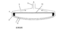
図1は、従来技術によるガラス曲げプロセス用の工具を示す。この工具は、積み重なった2つのガラス板I,IIを吸引作用により重力の影響に抗して枠状の凸の接触面2に保持するに好適な上側の型である。接触面2は、「スケルトン(Skelett)13」に配置されている。吸引作用を発生すべく、工具は、空気を吸い出す吸引管5を備える。さらに工具は、カバー3を備え、カバー3の端部は、周囲を取り巻くように延びる空気案内板4を有する。空気案内板4は、接触面2の周囲を取り巻くように延び、これを包囲する。曲げスケルトン13と、空気案内板4を有するカバー3とにより、吸引管により発生された空気流は、ガラス板のエッジに沿うように案内される。これによりガラス板対I,IIは、確実に接触面2に保持される。
FIG. 1 shows a tool for a glass bending process according to the prior art. This tool is an upper mold suitable for holding two stacked glass plates I and II on the frame-shaped
板I,IIは、例えば重力曲げにより下側の曲げ型内で曲げられている。図示の工具は、例えばガラス板対I,IIを下側の型からピックアップし、別の型に引き渡すために使用され得る。例えばガラス板対I,IIは、プレス曲げプロセスにかけられてもよく、プレス曲げプロセスの場合、図示の工具と相手側の型との間で圧力作用及び/又は吸引作用が働くことで変形される。 The plates I and II are bent in the lower bending die by, for example, gravity bending. The illustrated tool can be used, for example, to pick up a pair of glass plates I, II from a lower mold and deliver it to another mold. For example, the glass plate pairs I and II may be subjected to a press bending process, and in the case of the press bending process, the pressure action and / or the suction action acts between the illustrated tool and the opposite mold. .
図示の工具及び当該工具を使用可能な曲げ方法は、欧州特許第1836136号明細書(EP 1 836 136 B1)、国際公開第2012/080071号(WO 2012/080071 A1)及び国際公開第2012/080072号(WO 2012/080072 A1)において公知である。
The illustrated tool and the bending method in which the tool can be used are disclosed in European Patent No. 1836136 (
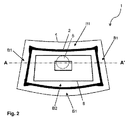
図2及び図3は、それぞれ、改良を加えた本発明に係る工具1の詳細を示している。工具1は、図1に示した工具と同様、曲げプロセス用の上側の型である。図2は、工具1の、曲げたいガラス板との接触が予定される下側の面の平面図である一方、図3は、断面図である。
2 and 3 show details of the
曲げ工具1は、図1の工具と同様、吸引作用を発生させる吸引管5と、空気案内板4を有するカバー3と、枠状の接触面2を有する曲げスケルトン13とを備える。公知の工具とは異なり、吸引作用は、曲げ工具内で適切に分配され、これにより、最適化された圧力分布が形成される。
The
曲げ工具は、2つの異なる圧力領域B1及びB2を備え、圧力領域B1及びB2内には、互いに異なる圧力が形成可能であり、これらの互いに異なる圧力は、ガラス板I,IIに作用する。第1の圧力領域B1は、周囲を取り巻くように概ね空気案内板4と接触面2との間に配置されている。第2の圧力領域B2は、工具1の、接触面2により包囲される中央領域に配置されている。
The bending tool includes two different pressure regions B1 and B2, and different pressures can be formed in the pressure regions B1 and B2, and these different pressures act on the glass plates I and II. The first pressure region B1 is generally disposed between the
工具1は、第1の圧力領域B1に減じられた第1の圧力p1を発生させるに好適である。この圧力p1は、空気案内板4と接触面2との間において空気流を上向きに方向付ける。単数又は複数のガラス板I,IIが本発明において曲げ工具1と接触しているとき、空気流はガラス板のサイドエッジに沿う。この空気流は、1つのガラス板又は積み重なった複数のガラス板を重力の作用に抗して工具1の接触面に保持するに好適である。つまり、第1の圧力領域B1における第1の圧力p1は、図1に示した従来技術の工具における空気流の機能を果たす。それぞれ約2.1mmの典型的な板厚を有するガラス板対I,IIを保持するには、例えば、周囲圧に対して3mbar乃至6mbarの負圧に相当する第1の圧力p1が好適である。
The
さらに工具1は、第2の圧力領域B2に、第1の圧力p1より大きい第2の圧力p2を発生させるに好適である。つまり、第2の圧力領域B2における吸引作用は、第1の圧力領域B1における吸引作用より弱い。第2の圧力領域B2は、板の予備曲げ、特に板の中央領域における予備曲げに対して吸引作用が不都合な影響を及ぼすことを阻止する。図に看取可能であるように、板の中央領域における強い吸引作用は、予備曲げとは逆方向に作用し、これにより、予備曲げが減じられてしまうか、又はそれどころか「逆向きの曲げ」が中央領域に形成されてしまうおそれがある。このことは、第2の圧力領域B2を備える本発明に係る工具により効果的に回避可能である。典型的な第2の圧力p2は、例えば、周囲圧に略等しいか、又は僅かにのみ周囲圧を下回り、例えば1mbarの負圧を有する。
Furthermore, the
複数の圧力領域に前述のように分配するに好適な、吸引管5内の負圧は、例えば約80mbarである。 A negative pressure in the suction tube 5 suitable for distributing to a plurality of pressure regions as described above is, for example, about 80 mbar.
吸引作用を発生すべく、工具1は、吸引管5を備えている。吸引管5は、やはり、工具1の、接触面2から背離した側、つまり、上側に配置されている。圧力領域B1及びB2は、吸引管に接続されており、これにより、減じられた圧力が発生される。カバー3と、接触面2を担持するスケルトン13とは、第1の圧力領域B1と吸引管5との間のラインを形成する。吸引管5は、図2の平面図では本来看取不能であるが、吸引管5の位置を破線により略示した。
In order to generate a suction action, the
第2の圧力領域B2は、吸引管5への(図面には示さない)接続を有し、これにより、第2の圧力領域B2にも、減じられた圧力が発生される。第2の圧力p2を高めるために、工具1は、通気管7を備える。通気管7は、スケルトン13とカバー3との間を延び、第2の圧力領域B2を周囲に、工具1の、接触面2から背離した側において接続する。第2の圧力p2は、吸引管5の吸引作用と、通気管7を通して流れ込む空気とにより生じる。第2の圧力p2の能動制御のために、弁12を有する通気管7が設けられている。流れ込む空気は、図面に矢印で示した。
The second pressure region B2 has a connection (not shown in the drawing) to the suction pipe 5, so that a reduced pressure is also generated in the second pressure region B2. In order to increase the second pressure p 2 , the
スケルトン13には、中央の開口を有する変向板8が設けられている。変向板8が、通気管7を通して流れ込む空気を変向させるので、空気は、略中心にて第2の圧力領域B2に流入する。これにより、均一な拡散が達成される。空気の均一な拡散は、ガラス板の表面にとって有利である。1つの中央の通気管を中心部に取り付けることは、図示の構成では、不可能である。それというのも、このために必要なスペースには、中央の吸引管5があるからである。
The
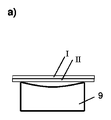
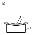
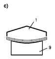
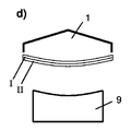
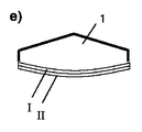
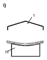
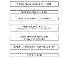
図4は、本発明に係る方法の一実施の形態のステップを略示する。まず、初期状態では平らな、積み重なった2つのガラス板I,IIを下側の曲げ型9上に位置決めする(部分図a)。曲げ型9上の板を曲げ温度、例えば600℃に加熱し、重力の作用により下側の曲げ型9の形状に密着させる(部分図b)。つまり、ガラス板I,IIを重力曲げにより予備曲げする。重力曲げ後、ガラス板I,IIを本発明に係る工具1により受け取る。このために工具1を上方より下側の曲げ型9上のガラス板I,IIに接近させ、接触面2と接触させる(部分図c)。続いて吸引管5を介して吸引作用を発生させる。第1の圧力p1に基づいてガラス板I,IIを曲げ工具1に保持する。ガラス板I,IIは、曲げ工具1により上方に動かし得る状態、ひいては下側の曲げ型9から取り出し得る状態となる(部分図d)。第2の圧力p2は、板中心部における曲げ欠陥を阻止する。ガラス板を曲げ工具1により受け取った後(部分図e)、下側の吸引曲げ型10を下方よりガラス板I,IIに接近させる。ガラス板I,IIを本発明に係る工具1と下側の吸引曲げ型10との間でプレス曲げによりガラス板I,IIの最終的な形状に曲げる(部分図f)。続いて下側の吸引曲げ型10を再び下降させ(部分図g)、ガラス板I,IIを曲げ工具1により下側の保持型11上に下ろし、吸引作用を停止することでこの保持型11に引き渡す(部分図h)。その後、曲げ工具1を上方に動かして(部分図i)、次の板対の曲げプロセスに備える。ガラス板I,IIを下側の保持型11上で周囲温度まで冷ます。下側の保持型11として第1の下側の曲げ型9(重力曲げ型)と同じ型又は同じに形成された型を使用してもよい。
FIG. 4 schematically shows the steps of an embodiment of the method according to the invention. First, two glass plates I and II that are flat and stacked in the initial state are positioned on the lower bending die 9 (partial view a). The plate on the bending die 9 is heated to a bending temperature, for example, 600 ° C., and is brought into close contact with the shape of the lower bending die 9 by the action of gravity (partial view b). That is, the glass plates I and II are preliminarily bent by gravity bending. After gravity bending, the glass plates I and II are received by the
ここに略示した方法ステップは、欧州特許第1836136号明細書(EP 1 836 136 B1)に詳細に説明される方法を再現し、そこで使用される上側の型(forme superieure 11)を本発明に係る工具1に置換したものである。
The method steps outlined here reproduce the method described in detail in EP 1836136 (
図5は、図4に示した実施例のフローチャートである。 FIG. 5 is a flowchart of the embodiment shown in FIG.
1 少なくとも1つのガラス板を保持する本発明に係る工具
2 枠状の接触面
3 カバー
4 空気案内板
5 吸引管
7 通気管
8 変向板
9 第1の下側の曲げ型/重力曲げ型
10 第2の下側の曲げ型/吸引曲げ型
11 下側の保持型
12 7の弁
13 1のスケルトン
B1 第1の圧力領域
B2 第2の圧力領域
p1 減じられた第1の圧力
p2 第2の圧力
I ガラス板
II ガラス板
DESCRIPTION OF
Claims (15)
前記空気案内板(4)と前記接触面(2)との間の第1の圧力領域(B1)に、減じられた第1の圧力(p1)を発生させ、
前記接触面(2)より内側の中央領域に配置されている第2の圧力領域(B2)に、前記第1の圧力(p1)より大きい第2の圧力(p2)を発生させる、
に好適であることを特徴とする、工具(1)。 A tool (1) for holding at least one glass plate (I, II) by suction in a bending process, wherein the frame-like convex contact surface (2) and the contact surface (2) are at least partially A cover (3) having a surrounding air guide plate (4) surrounding the tool (1),
Generating a reduced first pressure (p 1 ) in a first pressure region (B1) between the air guide plate (4) and the contact surface (2);
Generating a second pressure (p 2 ) greater than the first pressure (p 1 ) in a second pressure region (B 2) disposed in a central region inside the contact surface (2);
Tool (1), characterized in that it is suitable for
前記ガラス板(I,II)を前記工具(1)により前記第1の下側の型(9)からピックアップし、別の型に引き渡す、
請求項7又は8に記載の方法。 Heating the glass plate (I, II) to the bending temperature, pre-bending on the first lower mold (9),
The glass plate (I, II) is picked up from the first lower mold (9) by the tool (1) and delivered to another mold,
The method according to claim 7 or 8.
Applications Claiming Priority (3)
| Application Number | Priority Date | Filing Date | Title |
|---|---|---|---|
| EP14190619.8 | 2014-10-28 | ||
| EP14190619 | 2014-10-28 | ||
| PCT/EP2015/070430 WO2016066309A1 (en) | 2014-10-28 | 2015-09-08 | Tool for a glass-bending process |
Publications (2)
| Publication Number | Publication Date |
|---|---|
| JP2017537864A true JP2017537864A (en) | 2017-12-21 |
| JP6362777B2 JP6362777B2 (en) | 2018-07-25 |
Family
ID=51845292
Family Applications (1)
| Application Number | Title | Priority Date | Filing Date |
|---|---|---|---|
| JP2017523224A Expired - Fee Related JP6362777B2 (en) | 2014-10-28 | 2015-09-08 | Tools for glass bending process |
Country Status (14)
| Country | Link |
|---|---|
| US (1) | US10562803B2 (en) |
| EP (1) | EP3212585B1 (en) |
| JP (1) | JP6362777B2 (en) |
| KR (1) | KR101911654B1 (en) |
| CN (1) | CN106458686B (en) |
| BR (1) | BR112017001769B1 (en) |
| CA (1) | CA2956049C (en) |
| EA (1) | EA032544B1 (en) |
| ES (1) | ES2713032T3 (en) |
| MX (1) | MX2017005445A (en) |
| PL (1) | PL3212585T3 (en) |
| PT (1) | PT3212585T (en) |
| TR (1) | TR201902286T4 (en) |
| WO (1) | WO2016066309A1 (en) |
Cited By (1)
| Publication number | Priority date | Publication date | Assignee | Title |
|---|---|---|---|---|
| WO2022168698A1 (en) * | 2021-02-03 | 2022-08-11 | Agc株式会社 | Bend molding apparatus and bend molding method |
Families Citing this family (8)
| Publication number | Priority date | Publication date | Assignee | Title |
|---|---|---|---|---|
| US10597320B2 (en) | 2014-10-28 | 2020-03-24 | Saint-Gobain Glass France | Bending tool for glass panes |
| CA2992391C (en) * | 2015-08-18 | 2019-12-31 | Saint-Gobain Glass France | Glass bending device and glass bending method using a fan |
| KR102051876B1 (en) | 2015-09-08 | 2019-12-04 | 쌩-고벵 글래스 프랑스 | Overpressure-assisted gravity bending method and apparatus suitable therefor |
| ES2733808T3 (en) | 2015-11-25 | 2019-12-03 | Saint Gobain | Gravity curved method reinforced by overpressure and suitable device for it |
| PE20180956A1 (en) | 2016-01-28 | 2018-06-12 | Saint Gobain | GLASS BENDING METHOD SUPPORTED BY POSITIVE PRESSURE AND APPROPRIATE DEVICE FOR SAME |
| DE102017207452A1 (en) | 2017-05-03 | 2018-11-08 | Faurecia Innenraum Systeme Gmbh | Method and mold for producing a component for use in a vehicle interior |
| CN111263735A (en) * | 2018-10-01 | 2020-06-09 | 法国圣戈班玻璃厂 | Tool, system and method for manufacturing vehicle glass, vehicle glass and vehicle |
| CN113060929B (en) * | 2021-04-09 | 2022-12-20 | 福耀玻璃工业集团股份有限公司 | Automobile glass forming die and production method |
Citations (8)
| Publication number | Priority date | Publication date | Assignee | Title |
|---|---|---|---|---|
| JPS49110710A (en) * | 1973-02-22 | 1974-10-22 | ||
| US4229199A (en) * | 1979-05-21 | 1980-10-21 | Ppg Industries, Inc. | Shaping glass sheets by drop forming with differential vacuum release |
| JPS6327443U (en) * | 1986-08-08 | 1988-02-23 | ||
| JPH03131540A (en) * | 1989-07-18 | 1991-06-05 | Saint Gobain Vitrage Internatl | Method and device for manufacture of bent and/or glazing glass pane |
| JPH04357130A (en) * | 1990-01-19 | 1992-12-10 | Saint Gobain Vitrage Internatl | Method and apparatus for manufacturing curved glass sheet |
| JP2002527349A (en) * | 1998-10-21 | 2002-08-27 | サン−ゴバン・ヴイトラージユ | Method and apparatus for bending sheet glass |
| JP2008526659A (en) * | 2004-12-31 | 2008-07-24 | サン−ゴバン グラス フランス | Method for curving a glass sheet by suction |
| JP2014504229A (en) * | 2010-12-13 | 2014-02-20 | サン−ゴバン グラス フランス | Curved window plate |
Family Cites Families (18)
| Publication number | Priority date | Publication date | Assignee | Title |
|---|---|---|---|---|
| FR2085464B1 (en) | 1970-04-23 | 1974-08-09 | Saint Gobain Pont A Mousson | |
| US4511386A (en) * | 1983-05-24 | 1985-04-16 | Ppg Industries, Inc. | Deformable vacuum holder used to shape glass sheets |
| JPS61127628A (en) * | 1984-11-26 | 1986-06-14 | Nippon Sheet Glass Co Ltd | Forming die for glass |
| US4877437A (en) | 1988-04-29 | 1989-10-31 | Glasstech International L.P. | Vacuum platen for sharp bends |
| JPH06256030A (en) * | 1993-03-02 | 1994-09-13 | Nippon Sheet Glass Co Ltd | Bending of sheet glass |
| FR2707283B1 (en) * | 1993-07-09 | 1995-09-22 | Saint Gobain Vitrage Int | Method and device for forming glass plates and application of this method to obtaining glazings of complex shapes. |
| US5669952A (en) | 1994-10-14 | 1997-09-23 | Ppg Industries, Inc. | Pressure forming of glass sheets |
| US5833729A (en) * | 1996-12-16 | 1998-11-10 | Ppg Industries, Inc. | Method and apparatus for bending glass sheets |
| DE10105200A1 (en) | 2001-02-06 | 2002-08-14 | Saint Gobain | Method and device for bending glass sheets in pairs |
| US6543255B2 (en) * | 2001-06-19 | 2003-04-08 | Glasstech, Inc. | Press bending station and method for job switching |
| KR100825699B1 (en) * | 2002-03-13 | 2008-04-29 | 아사히 가라스 가부시키가이샤 | Method of bend molding glass plate and apparatus |
| US20030182969A1 (en) * | 2002-03-28 | 2003-10-02 | Dunifon Thomas A. | Glass handling and locating system |
| FR2852951B1 (en) * | 2003-03-26 | 2007-02-16 | Saint Gobain | METHOD FOR BOMBING GLASS SHEETS BY PRESSING AND SUCTION |
| CN2641043Y (en) * | 2003-07-29 | 2004-09-15 | 洛阳北方玻璃技术股份有限公司 | Glass lifting negative pressure mould loader in bend toughened glasls prodn. equipment |
| CN101883739B (en) * | 2007-12-04 | 2013-06-05 | 旭硝子株式会社 | Glass pane bending and forming method, and glass pane bending and forming apparatus |
| EP2463248A1 (en) | 2010-12-13 | 2012-06-13 | Saint-Gobain Glass France | Method and device for bending sheets |
| EP2463247A1 (en) | 2010-12-13 | 2012-06-13 | Saint-Gobain Glass France | Method and device for bending discs |
| US10597320B2 (en) | 2014-10-28 | 2020-03-24 | Saint-Gobain Glass France | Bending tool for glass panes |
-
2015
- 2015-09-08 JP JP2017523224A patent/JP6362777B2/en not_active Expired - Fee Related
- 2015-09-08 EP EP15763278.7A patent/EP3212585B1/en active Active
- 2015-09-08 CN CN201580021087.3A patent/CN106458686B/en not_active Expired - Fee Related
- 2015-09-08 BR BR112017001769-5A patent/BR112017001769B1/en not_active IP Right Cessation
- 2015-09-08 PT PT15763278T patent/PT3212585T/en unknown
- 2015-09-08 KR KR1020177011131A patent/KR101911654B1/en active IP Right Grant
- 2015-09-08 ES ES15763278T patent/ES2713032T3/en active Active
- 2015-09-08 EA EA201790260A patent/EA032544B1/en not_active IP Right Cessation
- 2015-09-08 CA CA2956049A patent/CA2956049C/en not_active Expired - Fee Related
- 2015-09-08 MX MX2017005445A patent/MX2017005445A/en unknown
- 2015-09-08 PL PL15763278T patent/PL3212585T3/en unknown
- 2015-09-08 US US15/328,475 patent/US10562803B2/en not_active Expired - Fee Related
- 2015-09-08 TR TR2019/02286T patent/TR201902286T4/en unknown
- 2015-09-08 WO PCT/EP2015/070430 patent/WO2016066309A1/en active Application Filing
Patent Citations (8)
| Publication number | Priority date | Publication date | Assignee | Title |
|---|---|---|---|---|
| JPS49110710A (en) * | 1973-02-22 | 1974-10-22 | ||
| US4229199A (en) * | 1979-05-21 | 1980-10-21 | Ppg Industries, Inc. | Shaping glass sheets by drop forming with differential vacuum release |
| JPS6327443U (en) * | 1986-08-08 | 1988-02-23 | ||
| JPH03131540A (en) * | 1989-07-18 | 1991-06-05 | Saint Gobain Vitrage Internatl | Method and device for manufacture of bent and/or glazing glass pane |
| JPH04357130A (en) * | 1990-01-19 | 1992-12-10 | Saint Gobain Vitrage Internatl | Method and apparatus for manufacturing curved glass sheet |
| JP2002527349A (en) * | 1998-10-21 | 2002-08-27 | サン−ゴバン・ヴイトラージユ | Method and apparatus for bending sheet glass |
| JP2008526659A (en) * | 2004-12-31 | 2008-07-24 | サン−ゴバン グラス フランス | Method for curving a glass sheet by suction |
| JP2014504229A (en) * | 2010-12-13 | 2014-02-20 | サン−ゴバン グラス フランス | Curved window plate |
Cited By (1)
| Publication number | Priority date | Publication date | Assignee | Title |
|---|---|---|---|---|
| WO2022168698A1 (en) * | 2021-02-03 | 2022-08-11 | Agc株式会社 | Bend molding apparatus and bend molding method |
Also Published As
| Publication number | Publication date |
|---|---|
| CN106458686B (en) | 2019-06-18 |
| KR101911654B1 (en) | 2018-12-19 |
| ES2713032T3 (en) | 2019-05-17 |
| KR20170057425A (en) | 2017-05-24 |
| BR112017001769B1 (en) | 2022-02-01 |
| EP3212585B1 (en) | 2018-12-26 |
| WO2016066309A1 (en) | 2016-05-06 |
| CA2956049C (en) | 2019-01-08 |
| JP6362777B2 (en) | 2018-07-25 |
| US20170217820A1 (en) | 2017-08-03 |
| TR201902286T4 (en) | 2019-03-21 |
| BR112017001769A2 (en) | 2019-11-12 |
| PL3212585T3 (en) | 2019-05-31 |
| MX2017005445A (en) | 2017-06-29 |
| CN106458686A (en) | 2017-02-22 |
| EP3212585A1 (en) | 2017-09-06 |
| EA201790260A1 (en) | 2017-08-31 |
| US10562803B2 (en) | 2020-02-18 |
| CA2956049A1 (en) | 2016-05-06 |
| PT3212585T (en) | 2019-03-01 |
| EA032544B1 (en) | 2019-06-28 |
Similar Documents
| Publication | Publication Date | Title |
|---|---|---|
| JP6362777B2 (en) | Tools for glass bending process | |
| JP6373495B2 (en) | Bending tool for glass plate | |
| JP6498354B2 (en) | Glass bending apparatus and glass bending method using blower | |
| US9771297B2 (en) | Method for cambering glass sheets by suction | |
| EP3102546B1 (en) | Three stage forming of glass sheet with transverse curvature | |
| RU2720538C2 (en) | Method of glass bending supported by excessive pressure and device suitable for this purpose | |
| JP6438487B2 (en) | Forming station and method for forming hot glass sheet with longitudinal and transverse curvature | |
| JP2018531866A (en) | Gravity curve method assisted by positive pressure and apparatus suitable for this method | |
| JP2006521272A (en) | Method and apparatus for bending glass sheets | |
| JPS6345138A (en) | Bending method for glass plate | |
| JP6792090B2 (en) | Gravity bending mold for bending glass panes with a curved support surface | |
| JPH0230632A (en) | Flexural forming process for laminated raw plate glass for laminated glass and unit therefor |
Legal Events
| Date | Code | Title | Description |
|---|---|---|---|
| A131 | Notification of reasons for refusal |
Free format text: JAPANESE INTERMEDIATE CODE: A131 Effective date: 20180319 |
|
| A521 | Request for written amendment filed |
Free format text: JAPANESE INTERMEDIATE CODE: A523 Effective date: 20180607 |
|
| TRDD | Decision of grant or rejection written | ||
| A01 | Written decision to grant a patent or to grant a registration (utility model) |
Free format text: JAPANESE INTERMEDIATE CODE: A01 Effective date: 20180618 |
|
| A61 | First payment of annual fees (during grant procedure) |
Free format text: JAPANESE INTERMEDIATE CODE: A61 Effective date: 20180626 |
|
| R150 | Certificate of patent or registration of utility model |
Ref document number: 6362777 Country of ref document: JP Free format text: JAPANESE INTERMEDIATE CODE: R150 |
|
| R250 | Receipt of annual fees |
Free format text: JAPANESE INTERMEDIATE CODE: R250 |
|
| LAPS | Cancellation because of no payment of annual fees |