JP2017537577A - Piezoelectric sensor, device and method using piezo channel - Google Patents
Piezoelectric sensor, device and method using piezo channel Download PDFInfo
- Publication number
- JP2017537577A JP2017537577A JP2017543892A JP2017543892A JP2017537577A JP 2017537577 A JP2017537577 A JP 2017537577A JP 2017543892 A JP2017543892 A JP 2017543892A JP 2017543892 A JP2017543892 A JP 2017543892A JP 2017537577 A JP2017537577 A JP 2017537577A
- Authority
- JP
- Japan
- Prior art keywords
- piezoelectric sensor
- signal
- channel
- microcontroller
- piezoelectric
- Prior art date
- Legal status (The legal status is an assumption and is not a legal conclusion. Google has not performed a legal analysis and makes no representation as to the accuracy of the status listed.)
- Granted
Links
- 238000000034 method Methods 0.000 title claims description 5
- 101150039289 PZF1 gene Proteins 0.000 claims abstract description 24
- 238000005452 bending Methods 0.000 claims description 6
- 230000004044 response Effects 0.000 claims description 5
- 238000001514 detection method Methods 0.000 claims description 3
- 238000013461 design Methods 0.000 abstract description 3
- 238000010586 diagram Methods 0.000 description 5
- 230000008901 benefit Effects 0.000 description 3
- 238000007792 addition Methods 0.000 description 1
- 238000013459 approach Methods 0.000 description 1
- 238000010276 construction Methods 0.000 description 1
- 238000012937 correction Methods 0.000 description 1
- 238000013016 damping Methods 0.000 description 1
- 230000000694 effects Effects 0.000 description 1
- 238000005259 measurement Methods 0.000 description 1
- 238000012986 modification Methods 0.000 description 1
- 230000004048 modification Effects 0.000 description 1
- 239000013641 positive control Substances 0.000 description 1
- 230000000630 rising effect Effects 0.000 description 1
- 230000011664 signaling Effects 0.000 description 1
Images


Classifications
-
- H—ELECTRICITY
- H03—ELECTRONIC CIRCUITRY
- H03K—PULSE TECHNIQUE
- H03K17/00—Electronic switching or gating, i.e. not by contact-making and –breaking
- H03K17/94—Electronic switching or gating, i.e. not by contact-making and –breaking characterised by the way in which the control signals are generated
- H03K17/96—Touch switches
- H03K17/964—Piezoelectric touch switches
- H03K17/9643—Piezoelectric touch switches using a plurality of detectors, e.g. keyboard
-
- G—PHYSICS
- G06—COMPUTING; CALCULATING OR COUNTING
- G06F—ELECTRIC DIGITAL DATA PROCESSING
- G06F3/00—Input arrangements for transferring data to be processed into a form capable of being handled by the computer; Output arrangements for transferring data from processing unit to output unit, e.g. interface arrangements
- G06F3/01—Input arrangements or combined input and output arrangements for interaction between user and computer
- G06F3/016—Input arrangements with force or tactile feedback as computer generated output to the user
-
- G—PHYSICS
- G06—COMPUTING; CALCULATING OR COUNTING
- G06F—ELECTRIC DIGITAL DATA PROCESSING
- G06F3/00—Input arrangements for transferring data to be processed into a form capable of being handled by the computer; Output arrangements for transferring data from processing unit to output unit, e.g. interface arrangements
- G06F3/01—Input arrangements or combined input and output arrangements for interaction between user and computer
- G06F3/048—Interaction techniques based on graphical user interfaces [GUI]
-
- H—ELECTRICITY
- H10—SEMICONDUCTOR DEVICES; ELECTRIC SOLID-STATE DEVICES NOT OTHERWISE PROVIDED FOR
- H10N—ELECTRIC SOLID-STATE DEVICES NOT OTHERWISE PROVIDED FOR
- H10N30/00—Piezoelectric or electrostrictive devices
- H10N30/30—Piezoelectric or electrostrictive devices with mechanical input and electrical output, e.g. functioning as generators or sensors
- H10N30/302—Sensors
-
- H—ELECTRICITY
- H10—SEMICONDUCTOR DEVICES; ELECTRIC SOLID-STATE DEVICES NOT OTHERWISE PROVIDED FOR
- H10N—ELECTRIC SOLID-STATE DEVICES NOT OTHERWISE PROVIDED FOR
- H10N30/00—Piezoelectric or electrostrictive devices
- H10N30/80—Constructional details
- H10N30/802—Circuitry or processes for operating piezoelectric or electrostrictive devices not otherwise provided for, e.g. drive circuits
-
- H—ELECTRICITY
- H03—ELECTRONIC CIRCUITRY
- H03K—PULSE TECHNIQUE
- H03K2217/00—Indexing scheme related to electronic switching or gating, i.e. not by contact-making or -breaking covered by H03K17/00
- H03K2217/94—Indexing scheme related to electronic switching or gating, i.e. not by contact-making or -breaking covered by H03K17/00 characterised by the way in which the control signal is generated
- H03K2217/96—Touch switches
- H03K2217/96062—Touch switches with tactile or haptic feedback
Landscapes
- Engineering & Computer Science (AREA)
- General Engineering & Computer Science (AREA)
- Theoretical Computer Science (AREA)
- Human Computer Interaction (AREA)
- Physics & Mathematics (AREA)
- General Physics & Mathematics (AREA)
- Electronic Switches (AREA)
- General Electrical Machinery Utilizing Piezoelectricity, Electrostriction Or Magnetostriction (AREA)
Abstract
回路設計を単純化するため、圧電センサ(2´)が提案される。圧電センサ(2´)は、マイクロコントローラ(26)と、複数の圧電センサ素子(20)と、を含み、当該複数の圧電センサ素子うちの少なくとも2つは、i)圧電センサ素子(20)の各々に各々のスイッチ(1105)を介して接続されたブーストコンバータ(1101)によって生成される電圧(HV)によって触覚信号を発生させるために用いることができ、ii)マイクロコントローラ(26)のピエゾチャネル(PZF1;PZF2;PZF3)に接続されている。圧電センサ(2´)は、スイッチ(1105)の各々を個別に制御するためのマルチプレクサ(80)をさらに含み、昇圧ピン(53)からのイネーブル信号(DRVP)が存在する場合に、各々のピエゾチャネル(PZF1;PZF2;PZF3)に接続されたデジタル選択ラインに信号が示される。当該マイクロコントローラ(26)は、:i) ピエゾチャネル(PZF1;PZF2;PZF3)の各々をそれぞれの圧電センサ素子(20)からのセンサ入力を読み取るためのセンサチャネルとして用いるように;そして、ii)ピエゾチャネル(PZF1;PZF2;PZF3)の少なくとも1つにおける、センサ入力の検出に応答して、a)昇圧ピン(53)においてイネーブル信号(DRVP)を設定し、及び/又はイネーブル信号ピン(54)(DRVP、HVEN)において信号(HVEN)を設定し、iib)センサ入力が検出された少なくとも1つのピエゾチャネル(PZF1;PZF2;PZF3)に信号を設定して、それぞれの圧電センサ素子(20)によって触覚信号を生成し、当該信号は、センサ入力に関して、タイムインターリーブの態様で設定されるように構成されている。In order to simplify the circuit design, a piezoelectric sensor (2 ') is proposed. The piezoelectric sensor (2 ′) includes a microcontroller (26) and a plurality of piezoelectric sensor elements (20), and at least two of the plurality of piezoelectric sensor elements are i) of the piezoelectric sensor element (20). Can be used to generate a haptic signal by a voltage (HV) generated by a boost converter (1101) connected to each via a respective switch (1105), and ii) a piezo channel of a microcontroller (26) (PZF1; PZF2; PZF3). The piezoelectric sensor (2 ′) further includes a multiplexer (80) for individually controlling each of the switches (1105), and each piezoelectric element when there is an enable signal (DRVP) from the boost pin (53). A signal is shown on the digital selection line connected to the channel (PZF1; PZF2; PZF3). The microcontroller (26) uses: i) to use each of the piezo channels (PZF1; PZF2; PZF3) as a sensor channel for reading the sensor input from the respective piezoelectric sensor element (20); and ii) Responsive to detecting sensor input in at least one of the piezo channels (PZF1; PZF2; PZF3) a) setting an enable signal (DRVP) at the boost pin (53) and / or enabling signal pin (54) (DRVP, HVEN) set a signal (HVEN), iib) set a signal to at least one piezo channel (PZF1; PZF2; PZF3) in which a sensor input is detected, and each piezoelectric sensor element (20) A tactile signal is generated, and the signal It is configured to be set in the manner of a sleeve.
Description
[技術分野]
本発明は、圧電入力センサ及びそのような圧電センサを用いるデバイスに関する。
[Technical field]
The present invention relates to a piezoelectric input sensor and a device using such a piezoelectric sensor.
[背景技術]
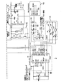
EP 2 770 638 A1号公報(その内容は参照されることで本明細書に包含される)(以下、`638号公報と称する)にて公開された本願の出願人の欧州特許出願には、少なくとも1つの圧電センサ素子を有する圧電スイッチ回路が開示されている。当該公報中の図10は本願の図1として再掲され、2つの圧電センサ素子を有する圧電スイッチ回路を示す。
[Background]
`637号公報に記載されかつ本願の図1にも示されている圧電スイッチ回路の圧電センサ素子は、当該圧電センサ素子が下方から取り付けられている表面に(例えば人間の指によって)及ぼされる圧力又は力に起因する力にさらされることによる圧電センサ素子の屈曲に起因する信号の検出だけでなく、当該表面を通して(例えば人間の指によって)感知され得る触覚信号(haptic signal)を発生させることにも利用され得る。 The piezoelectric sensor element of the piezoelectric switch circuit described in the '637 publication and also shown in FIG. 1 of the present application is the pressure exerted on the surface to which the piezoelectric sensor element is attached from below (for example, by a human finger). Or generating a haptic signal that can be sensed through the surface (eg, by a human finger) as well as detecting a signal due to bending of the piezoelectric sensor element by exposure to a force due to the force. Can also be used.
[発明の目的]
本発明の圧電スイッチ回路は、当該回路の一部である少なくとも1つの圧電センサ素子の屈曲に起因する信号を検出し、かつ`638号公報に開示された圧電スイッチ回路と同様に触覚信号を生成するように構成された圧電スイッチ回路である。当該触覚信号は、ブーストコンバータ(図1参照:ブーストコンバータ1101は高い電圧を生成し、当該電圧は数十ボルトから200−400ボルトの任意の電圧であっても良く、100−200ボルトであることが好ましい)によって、圧電センサ素子をスイッチングすることで生成される。スイッチ(図1参照:スイッチ1105、I又はスイッチ1105、II)がオープンである場合、各々の圧電センサ素子(図1参照:圧電センサ素子20、I又は20、II)は、タッチ(touch)スイッチとして使用できる。スイッチのうちの1つがクローズされている場合、各々の圧電センサ素子は触覚シグナリング手段(haptic signaling means)として使用できる。当該スイッチは、マイクロコントローラ(図1参照:マイクロコントローラ26)によって、ピン(図1参照:ピン52、I又はピン52、II)を介した信号(図1参照:シグナルDRVEN1又はシグナルDRVEN2)によって制御される。
[Object of invention]
The piezoelectric switch circuit of the present invention detects a signal resulting from bending of at least one piezoelectric sensor element that is a part of the circuit, and generates a haptic signal in the same manner as the piezoelectric switch circuit disclosed in the '638 publication. This is a piezoelectric switch circuit configured to do this. The haptic signal is a boost converter (see FIG. 1: the
圧電センサ素子の各々は、センサ入力を読み取るためのマイクロコントローラチャネルを必要とし、加えて、触覚信号を生成するために用いられる圧電センサ素子の各々は、触覚信号を切り替えるためのマイクロコントローラチャネルをさらに必要とする。従って、マイクロコントローラに要求されるチャネル数は触覚信号を生成するために用いられる圧電センサ素子の数の増加に伴って急激に増加するであろうと理解される。これは欠点と考えられている。 Each of the piezoelectric sensor elements requires a microcontroller channel for reading the sensor input, and in addition, each of the piezoelectric sensor elements used to generate the haptic signal further has a microcontroller channel for switching the haptic signal. I need. Accordingly, it is understood that the number of channels required for the microcontroller will increase rapidly with an increase in the number of piezoelectric sensor elements used to generate the haptic signal. This is considered a drawback.
本発明の目的は、複数の圧電センサを含み、そのうちの少なくとも2つは触覚信号の生成に利用可能である圧電センサにおいて触覚の信号を生成するという状況下で、回路設計を単純化することである。 It is an object of the present invention to simplify circuit design in the context of generating haptic signals in a piezoelectric sensor that includes a plurality of piezoelectric sensors, at least two of which are available for generating haptic signals. is there.
当該目的は、請求項1に記載の圧電センサ、請求項6に記載の圧電センサを含むデバイス、及び請求項7に記載の方法によって、実現されるであろう。
This object will be achieved by a piezoelectric sensor according to claim 1, a device comprising a piezoelectric sensor according to
[発明の利点]
本発明の圧電センサは、マイクロコントローラと、複数の圧電センサ素子を含み、当該圧電センサ素子のうちの少なくとも二つは、a)それぞれスイッチを介して各圧電センサ素子に接続されているブーストコンバータによって生成される電圧によって触覚信号を生成するために使用可能であり、b)マイクロコントローラのピエゾチャネルに接続されている。
[Advantages of the invention]
The piezoelectric sensor of the present invention includes a microcontroller and a plurality of piezoelectric sensor elements, and at least two of the piezoelectric sensor elements are a) by a boost converter connected to each piezoelectric sensor element via a switch. It can be used to generate a haptic signal with the generated voltage, and b) connected to the piezo channel of the microcontroller.
当該圧電センサは、各々のスイッチを個別に制御するマルチプレクサをさらに含み、昇圧ピン(increase voltage pin)からの信号が存在する場合に、それぞれのピエゾチャネルに接続されたデジタル選択ラインに信号が存在する。 The piezoelectric sensor further includes a multiplexer that individually controls each switch, and when a signal from an increase voltage pin is present, the signal is present on a digital selection line connected to each piezo channel. .
当該マイクロコントローラは:
i)それぞれの圧電センサ素子からのセンサ入力を読み取るために各々のピエゾチャネルをセンサチャネルとして用いるように;かつ
ii)ピエゾチャネルのうちの少なくとも1つにおけるセンサ入力の検出に応じて、昇圧ピンに信号を設定し、かつ/又はイネーブル信号ピンに信号を設定し、さらに、当該センサ入力が検出された少なくとも1つのピエゾチャネルに信号を設定し、それぞれの圧電センサ素子によって触覚信号を生成して、当該信号が、センサ入力に関してタイムインターリーブの態様で設定されるように構成されている。
The microcontroller is:
i) use each piezo channel as a sensor channel to read the sensor input from each piezoelectric sensor element; and
ii) In response to detection of sensor input in at least one of the piezo channels, a signal is set on the boost pin and / or a signal is set on the enable signal pin, and at least one of the sensor inputs detected A signal is set in one piezo channel, a tactile signal is generated by each piezoelectric sensor element, and the signal is set in a time-interleaved manner with respect to the sensor input.
当該圧電センサは、圧電センサ素子からのセンサ入力を収集すること、及び同じ圧電素子に触覚のフィードバックを発生するためのスイッチのクロージングをマルチプレクサに実行させるための信号を設定すること、の両方にピエゾチャネルが用いられ得るマイクロコントローラに関して、単純化された回路設計を可能にする。 The piezoelectric sensor piezos both to collect sensor input from the piezoelectric sensor element and to set a signal to cause the multiplexer to perform switch closing to generate tactile feedback on the same piezoelectric element. It enables a simplified circuit design for a microcontroller where the channel can be used.
当該ピエゾチャネルが圧電センサ素子の屈曲に起因する信号を読み取るための圧電センサ素子に接続されている場合、圧電センサの屈曲に起因する信号を収集するために、加えて、同じ圧電素子に触覚のフィードバックを発生するためのスイッチのクロージングをマルチプレクサに実行させるための信号を設定するために、同じピエゾチャネルが共有され得る。 If the piezo channel is connected to a piezoelectric sensor element for reading the signal due to the bending of the piezoelectric sensor element, in addition to collecting the signal due to the bending of the piezoelectric sensor, The same piezo channel can be shared to set the signal to cause the multiplexer to perform the closing of the switch to generate feedback.
ブーストコンバータは、マイクロコントローラの昇圧ピン及び/又はイネーブル信号ピンに、マイクロコントローラによって生成された信号が存在する場合に、当該電圧を生成するように構成され得る。或いは、ブーストコンバータは、マルチプレクサにおいてマルチプレクサ機能によって生成された信号が存在する場合に、当該電圧を生成するように構成され得る。当該信号は、マイクロコントローラの昇圧ピンからの信号に由来し得る。その場合、イネーブル信号ピンにおける信号は、マイクロコントローラの出力の際に必ずしも必要とされない。 The boost converter may be configured to generate the voltage when a signal generated by the microcontroller is present at the boost and / or enable signal pins of the microcontroller. Alternatively, the boost converter can be configured to generate the voltage when there is a signal generated by the multiplexer function in the multiplexer. The signal may be derived from a signal from the microcontroller boost pin. In that case, the signal at the enable signal pin is not necessarily required at the output of the microcontroller.
好ましくは、当該マイクロコントローラは、圧電センサ素子からセンサ入力を受信するために、かつ、マルチプレクサへのデジタル選択ラインに出力を与えるために、当該ピエゾチャネルをタイムインターリーブの態様で用いるように構成される。 Preferably, the microcontroller is configured to use the piezo channel in a time-interleaved manner to receive sensor input from the piezoelectric sensor element and to provide output to a digital select line to the multiplexer. .
当該デバイスは表面を含み、少なくとも1つの、本発明の第1の態様による圧電センサが当該表面に下方から取り付けられ、当該少なくとも1つの圧電センサは、当該表面を介した接触センサとして、かつ、当該表面を介して触覚のフィードバックを生成するために利用可能である。 The device includes a surface, and at least one piezoelectric sensor according to the first aspect of the invention is attached to the surface from below, the at least one piezoelectric sensor as a contact sensor through the surface and the It can be used to generate tactile feedback through the surface.
マイクロコントローラのピエゾチャネルを使用する方法において、ピエゾチャネルは、複数の圧電センサ素子の少なくとも1つからのセンサ入力を読み取るためのセンサチャネルとして用いられ、かつ、マルチプレクサへのデジタル選択ラインとして用いられてそれぞれのスイッチを介して各圧電センサ素子に接続されたブーストコンバータによって生成された電圧によって同じ圧電センサ素子において触覚信号を生成する。 In a method using a piezo channel of a microcontroller, the piezo channel is used as a sensor channel for reading a sensor input from at least one of a plurality of piezoelectric sensor elements and as a digital selection line to a multiplexer. A haptic signal is generated at the same piezoelectric sensor element by a voltage generated by a boost converter connected to each piezoelectric sensor element via a respective switch.
以下に、添付の図面の図3及び図4に示される実施形態の参照によって、本発明がより詳細に説明されるであろう。
全ての図において、同一の参照番号は、同一か又は同様の構造的要素を示す。 In all the figures, the same reference numerals indicate the same or similar structural elements.
[詳細な説明]
本発明による圧電デバイス2´の実施形態の例は、`638号公報において開示される圧電デバイス2への付加及び補正によって詳細に説明されるであろう。簡潔さのため、様々な構成要素及び対応する回路構成の、以下に明確には記載されない詳細な説明に関しては、`638号公報を引用する。
[Detailed description]
An example embodiment of a piezoelectric device 2 'according to the present invention will be described in detail by additions and corrections to the
さらに、デバイス1のより詳細な構造及びデバイス1における圧電デバイス2´の配置については、`638号公報の図1及び記載の対応する部分に譲る。デバイス1において、圧電デバイス2の代わりに圧電デバイス2´が配置されると理解される。圧電デバイス2´の構造は、以下に詳細に説明されるであろう構成要素及び対応する回路構成に関することを除いて他の機能及び実装に関しては、圧電デバイス2と同様であることが最も好ましい。
Furthermore, the more detailed structure of the device 1 and the arrangement of the
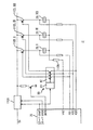
図2は、`638号公報に開示される図12の圧電デバイス2を示すが、図2においては、3つの触覚出力スイッチ1105を有している。理解され得るように、触覚出力スイッチ1105の数が増えるほど、マイクロコントローラのラインが必要とされるであろう(PZF1用のCH1、PZF2用のCH2、PZF3用のCH3)。実際、1つ以上の触覚出力チャネルが存在するように、触覚出力チャネルの数が選択され得る。`638号公報による実装において、触覚出力スイッチ1105の数は、触覚出力チャネルの数に等しい。
FIG. 2 shows the
図1からより容易に理解され得るように、各々の触覚出力スイッチ1105(例えば触覚出力スイッチ1105,I又は触覚出力スイッチ1105,II)は、制御可能でなければならず、マイクロコントローラ26に専用のチャネルを必要とする。触覚出力スイッチがクローズされている場合、ブーストコンバータ1101によって生成された高い電圧(背景技術の項で定義されるように)は、それぞれの圧電センサ素子20を越えて接続され、当該圧電センサ素子20を振動させて触覚フィードバックを生成する。
As can be more easily understood from FIG. 1, each haptic output switch 1105 (eg,
触覚信号の切り替えを制御するため及び圧電センサ素子20からの信号を検出するために、必要とされるマイクロコントローラ26のチャネルが少ないほど、現行のマイクロコントローラ26の構成によって、より多くのチャネルが使用できる。
The
ブーストコンバータ1101を動作させて触覚信号を生成する原理は、図1を参照することでより詳細に記述される。電圧制御された触覚出力スイッチ1105(例えばバイポーラトランジスタ又はFET)は、マイクロコントローラ26(例えば、PZポートピン)とオンボードで発生した電圧(例えば、HVEN)との間の電圧差によって制御される。通常の使用において、1つの触覚チャネルについて、PZ<i>ピンの1つは0Vまで引き下げられ、かつ、残りのピンはvdd(3.3V)まで引き上げられる。選択の有効化(enable)は、発生した電圧HVENを、HVENのベースノードを伴ってバイポーラトランジスタのVBEonの閾値電圧(0.6V)よりも高くすることによってなされる。当該トランジスタは、0Vに引き下げられたエミッタを有し、電流を伝導し、エミッタを有するトランジスタがvddにある間には、導通しない。HVENの電圧値は、VBEonとvdd(3.3V)との間の任意の値であり得、選択されたチャネルの導通及び選択されていないチャネルが導通しないことを確実にする。選択されていないチャネルのプルアップは、全く必要ではない:ピンのHZ(アナログ入力モード)ステートは、電流を防ぐために十分であるが、ノイズの多い環境においては、強制プルアップがより安全である。
The principle of operating the
HVEN信号は、DRVPがスイッチングアクティビティを有しかつロジック部81(図2参照)を低電圧と高電圧との間で切り替える場合にのみアクティブとなることが好ましい。当該電圧は、ダイオードなどのスイッチング素子8101によって整流され、トランジスタのベースに対して正の制御のみを提供し、導電性を増大する。DRVPにおけるスイッチングが終了する際に、選択トランジスタのベースノードはレジスタを介してグランドにドレインされ、PZピンの電圧に関わらず、全て非導電性となる。
The HVEN signal is preferably active only when DRVP has switching activity and the logic unit 81 (see FIG. 2) is switched between a low voltage and a high voltage. The voltage is rectified by a
触覚チャネルの選択は、触覚ブースターの上昇駆動(upward drive)の間にのみ必要となる。これは、トランジスタ1107による下降駆動(downward drive)は触覚出力スイッチ1105内のHVスイッチダイオード1106を利用してPHZ<i>ノードからのチャージをドレインするからである。
The selection of the haptic channel is only required during the upward drive of the haptic booster. This is because the downward drive by the
圧電センサ2´は、マイクロコントローラ26及び複数の圧電センサ素子20を含み、そのうちの少なくとも2つは:
−−各スイッチ1105を介して各々の圧電センサ素子20に接続されたブーストコンバータ1101によって生成された電圧HVによって、触覚信号を生成するために使用可能であり、
−−マイクロコントローラ26のピエゾチャネル(PZF1;PZF2;PZF3)に接続されている。
The piezoelectric sensor 2 'includes a
-Can be used to generate a haptic signal by a voltage HV generated by a
-It is connected to the piezo channel (PZF1; PZF2; PZF3) of the
圧電センサ2´は、各スイッチ1105を個別に制御するマルチプレクサ80をさらに含み、昇圧ピン(53)からの信号DRVPが存在する場合に、各ピエゾチャネル(PZF1;PZF2;PZF3)に接続されたデジタル選択ラインに信号が存在する。
The
マルチプレクサ80は、スイッチング部82において個別に制御され得るスイッチのアレイとして実装され得る。マイクロコントローラ26の昇圧ピン26に電気的に接続されたロジック部81は、スイッチング部82内のスイッチを個別に制御するように構成されている。当該スイッチング部82に関して、信号DRVPが昇圧ピン53に存在する場合に、各々のピエゾチャネル(PZF1;PZF2;PZF3)に信号が存在する。従って、各々のピエゾチャネル(PZF1;PZF2;PZF3)における信号が、各々のスイッチ1105を制御する。
当該マイクロコントローラ26は:
i)ピエゾチャネル(PZF1;PZF2;PZF3)の各々を、各圧電センサ素子20からのセンサ入力を読み取るためのセンサチャネルとして使用し;
ii)ピエゾチャネル(PZF1;PZF2;PZF3)の少なくとも1つにおけるセンサ入力の検出に応じて、
iia) 昇圧ピン53に信号DRVPを設定しかつイネーブル信号ピン54に信号HVENを設定し、
iib) センサ入力が検出されたピエゾチャネル(PZF1;PZF2;PZF3)の少なくとも1つに信号を設定して、各圧電センサ素子20によって触覚信号を生成するように構成されている。当該信号は短い遅延を伴い、少なくとも1つのピエゾチャネル(PZF1;PZF2;PZF3)における信号は、当該センサ入力に関してタイムインターリーブの態様で設定されるであろう。
The
i) each of the piezo channels (PZF1; PZF2; PZF3) is used as a sensor channel for reading the sensor input from each
ii) in response to detection of sensor input in at least one of the piezo channels (PZF1; PZF2; PZF3),
iii) Set signal DRVP on
iib) A signal is set to at least one of the piezo channels (PZF1; PZF2; PZF3) in which the sensor input is detected, and a tactile signal is generated by each
マイクロコントローラ26は、圧電センサ素子20からのセンサ入力を受け取るため及びマルチプレクサ80へのデジタル選択ラインに出力を与えるために、ピエゾチャネル(PZF1;PZF2;PZF3)をタイムインターリーブの態様で使用するように構成されている。
The
ピエゾチャネル(PZF1;PZF2;PZF3)は、圧電センサ素子20の屈曲に起因する信号を読み取るように、圧電センサ素子20に接続されていることが好ましい。
The piezo channel (PZF1; PZF2; PZF3) is preferably connected to the
図3は、圧電センサ2´の第1の実施形態を示す。マルチプレクサ80のロジック部81は、マイクロコントローラ26の昇圧ピン53に接続されている。当該昇圧ピン53はブーストコンバータ1101にさらに接続されている。
FIG. 3 shows a first embodiment of a
マイクロコントローラ26のイネーブル信号ピン54は、ブーストコンバータ1101に接続されている。ブーストコンバータ1101は、イネーブル信号ピン54に信号HVENが存在しかつ昇圧ピン53に信号DRVPが存在する場合に、高い電圧を生成する。
The enable
マルチプレクサ80は、そのスイッチング部82を動作させて、同時に昇圧信号(DRVP)が存在する場合に、各入力ライン(PZF1、PZF2、PZF3からの)において存在している信号に応答して出力ライン(触覚出力スイッチ1105、I;1105、II;1105、IIIに向かう)をトリガするように構成されている。
図3に示す実施形態において、ブーストコンバータ1101は、マイクロコントローラ26によって生成された信号DRVP及び/又は信号HVENが存在する場合に、電圧HVを生成するように構成されている。
In the embodiment shown in FIG. 3,
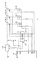
図4は、圧電センサ2´の代替的実施形態を示す。マイクロコントローラ26のイネーブル信号ピン54は必要とされないが、マルチプレクサ80のロジック部81は、マイクロコントローラ26の昇圧ピン53からの信号DRVPに由来する信号ENを誘導するために使用される。信号ENはマルチプレクサのロジック部81の出力からブーストコンバータ1101に接続されている。ブーストコンバータ1101は、信号ENが存在する場合に、電圧HVを生成するように構成されている。
FIG. 4 shows an alternative embodiment of the
図4に示すアプローチの利点は、この態様において、マイクロコントローラ26における1つのデジタル出力が他の目的で使用され得、マイクロコントローラ26で必要とされるリソースが削減され得ることである。
The advantage of the approach shown in FIG. 4 is that in this aspect, one digital output in the
他の実施形態において、ブーストコンバータ1101及びマルチプレクサ80の両方のための信号DRVPは、マイクロコントローラ26の適切な構成によって生成され得る。信号HVENは、イネーブル信号ピン54において上昇駆動中に生成される。この場合、信号HVENは、コンバータ1101及びマルチプレクサ80の両方を通過し得る。
In other embodiments, the signal DRVP for both the
マイクロコントローラ26のピエゾチャネル(PZF1;PZF2;PZF3)を使用する方法において、当該ピエゾチャネル(PZF1;PZF2;PZF3)は、
−複数の圧電センサ素子20のうちの少なくとも1つからのセンサ入力を読み取るためのセンサチャネルとして使用され、かつ、
−同じ圧電センサ素子20において、各圧電センサ素子20に各スイッチ1105を介して接続されたブーストコンバータ1101によって生成される電圧HVによって触覚信号を生成するための、マルチプレクサ80へのデジタル選択ラインとして使用される。
In the method using the piezo channel (PZF1; PZF2; PZF3) of the
-Used as a sensor channel for reading sensor input from at least one of the plurality of
-In the same
本発明の多くの特徴及び利点は、明細書から明白である。さらに、多数の改良及び変更が当業者にとって直ちに明白となるであろう。従って、当該発明は図示されかつ記載された構成及び作用そのものに限定されるべきではない。従って、全ての適切な改良及び同等のものは、発明の範囲内に収まるものとして再分類され得る。特に、圧電センサ2´の数は、3つでなくても良い。さらに、各圧電センサ2´は、接触信号がスイッチで切り替えられ得るように必ずしも構成されていなくても良い。 Many features and advantages of the invention are apparent from the description. In addition, many modifications and variations will be readily apparent to those skilled in the art. Accordingly, the invention should not be limited to the exact construction and operation shown and described. Accordingly, all suitable improvements and equivalents may be reclassified as falling within the scope of the invention. In particular, the number of piezoelectric sensors 2 'need not be three. Furthermore, each piezoelectric sensor 2 'does not necessarily have to be configured so that the contact signal can be switched by a switch.
1 デバイス
2、2´ 圧電センサ
20 圧電センサ素子
26 マイクロコントローラ
52 駆動チャネル
53 昇圧ピン
54 イネーブル信号ピン
80 マルチプレクサ
81 ロジック部
82 スイッチング部
132 セイフティアンドダンピングネットワーク
134 測定(入力)フィルタ
135 LED出力
136 I2Cバスコネクタ
137 オーディオ出力
1101 ブーストコンバータ
1105 触覚出力スイッチ
1107 トランジスタ
1108 レジスタ
1109 レジスタ
8101 スイッチング素子(例えば、ダイオード)
1
Claims (7)
マイクロコントローラ(26)と、
複数の圧電センサ素子(20;20、I;20、II;20、III)であって、前記複数の圧電センサ素子の少なくとも2つ(20、I;20、II)は:スイッチの各々(1105;1105、I;1105、II;1105、III)を介して圧電センサ素子の各々(20;20、I;20、II;20、III)に接続されたブーストコンバータ(1101)によって生成された電圧(HV)によって触覚信号を生成するために使用可能であり、かつ、前記マイクロコントローラ(26)のピエゾチャネル(PZF1;PZF2;PZF3)に接続されている前記複数の圧電センサ素子と、
昇圧ピン(53)からの信号(DRVP)が存在する場合に、前記ピエゾチャネルの各々(PZF1;PZF2;PZF3)に接続されたデジタル選択ラインに前記スイッチの各々(1105;1105、I;1105、II;1105、III)に関する信号が存在し、前記スイッチの各々を個別に制御するマルチプレクサ(80)と、を含み、
前記マイクロコントローラ(26)は:
i)前記ピエゾチャネルの各々(PZF1;PZF2;PZF3)を前記圧電センサ素子の各々(20;20、I;20、II;20、III)からのセンサ入力を読み取るためのセンサチャネルとして使用するように構成され、
ii)前記ピエゾチャネル(PZF1;PZF2;PZF3)の少なくとも1つにおけるセンサ入力の検出に応じて、
iia)前記昇圧ピン(53)において前記信号(DRVP)を設定し、かつ/又は、イネーブル信号ピン(54)において信号(HVEN)を設定し、
iib)前記センサ入力が検出された少なくとも1つのピエゾチャネル(PZF1;PZF2;PZF3)において信号を設定して前記圧電センサ素子の各々(20;20、I;20、II;20、III)によって触覚信号を生成し、前記信号は前記センサ入力に関してタイムインターリーブの態様で設定されるように構成されていることを特徴とする圧電センサ。 A piezoelectric sensor (2 '),
A microcontroller (26);
A plurality of piezoelectric sensor elements (20; 20, I; 20, II; 20, III), wherein at least two of the plurality of piezoelectric sensor elements (20, I; 20, II) are: each of the switches (1105) 1105, I; 1105, II; 1105, III) through the boost converter (1101) connected to each of the piezoelectric sensor elements (20; 20, I; 20, II; 20, III) A plurality of piezoelectric sensor elements that can be used to generate a haptic signal by (HV) and connected to a piezo channel (PZF1; PZF2; PZF3) of the microcontroller (26);
In the presence of a signal (DRVP) from the boost pin (53), each of the switches (1105; 1105, I; 1105, II; 1105, III) and a multiplexer (80) that individually controls each of the switches,
The microcontroller (26) is:
i) to use each of the piezo channels (PZF1; PZF2; PZF3) as a sensor channel for reading sensor inputs from each of the piezoelectric sensor elements (20; 20, I; 20, II; 20, III). Composed of
ii) in response to detection of sensor input in at least one of the piezo channels (PZF1; PZF2; PZF3),
ia) setting the signal (DRVP) at the boost pin (53) and / or setting the signal (HVEN) at the enable signal pin (54);
iib) setting a signal in at least one piezo channel (PZF1; PZF2; PZF3) where the sensor input is detected by each of the piezoelectric sensor elements (20; 20, I; 20, II; 20, III) A piezoelectric sensor configured to generate a signal, wherein the signal is set in a time-interleaved manner with respect to the sensor input.
複数の圧電センサ素子の少なくとも1つ(20;20、I;20、II;20、III)からのセンサ入力を読み取るためのセンサチャネルとして使用し、かつ、
タイムインターリーブの態様で、マルチプレクサ(80)へのデジタル選択ラインとして使用し、スイッチの各々(1105;1105、I;1105、II;1105、III)を介して圧電センサ素子の各々(20;20、I;20、II;20、III)に接続されたブーストコンバータ(1101)によって生成された電圧(HV)によって同じ前記圧電センサ素子(20;20、I;20、II;20、III)において触覚信号を生成する方法。 A method of using a piezo channel (PZF1; PZF2; PZF3) of a microcontroller (26), wherein the piezo channel is
As a sensor channel for reading sensor input from at least one of a plurality of piezoelectric sensor elements (20; 20, I; 20, II; 20, III); and
In a time-interleaved manner, it is used as a digital selection line to the multiplexer (80), and each of the piezoelectric sensor elements (20; 20,...) Via each of the switches (1105; 1105, I; Tactile in the same piezoelectric sensor element (20; 20, I; 20, II; 20, III) by a voltage (HV) generated by a boost converter (1101) connected to I; 20, II; 20, III) How to generate a signal.
Applications Claiming Priority (3)
| Application Number | Priority Date | Filing Date | Title |
|---|---|---|---|
| EP14192448.0 | 2014-11-10 | ||
| EP14192448.0A EP3018824A1 (en) | 2014-11-10 | 2014-11-10 | Piezoelectric sensor and a device comprising a piezoelectric sensor |
| PCT/EP2015/076193 WO2016075131A1 (en) | 2014-11-10 | 2015-11-10 | Piezoelectric sensor, a device and a method of using a piezo channel |
Publications (2)
| Publication Number | Publication Date |
|---|---|
| JP2017537577A true JP2017537577A (en) | 2017-12-14 |
| JP6595611B2 JP6595611B2 (en) | 2019-10-23 |
Family
ID=51868102
Family Applications (1)
| Application Number | Title | Priority Date | Filing Date |
|---|---|---|---|
| JP2017543892A Active JP6595611B2 (en) | 2014-11-10 | 2015-11-10 | Piezoelectric sensor, device and method using piezo channel |
Country Status (5)
| Country | Link |
|---|---|
| US (1) | US10665771B2 (en) |
| EP (2) | EP3018824A1 (en) |
| JP (1) | JP6595611B2 (en) |
| CN (1) | CN107112991B (en) |
| WO (1) | WO2016075131A1 (en) |
Cited By (1)
| Publication number | Priority date | Publication date | Assignee | Title |
|---|---|---|---|---|
| JP2021189167A (en) * | 2020-05-28 | 2021-12-13 | ボレアス テクノロジーズ インコーポレイテッド | High-resolution sensing of piezo-electric transducers |
Families Citing this family (8)
| Publication number | Priority date | Publication date | Assignee | Title |
|---|---|---|---|---|
| EP3018824A1 (en) | 2014-11-10 | 2016-05-11 | Aito Interactive Oy | Piezoelectric sensor and a device comprising a piezoelectric sensor |
| US10744053B2 (en) | 2016-12-07 | 2020-08-18 | Stryker Corporation | Haptic systems and methods for a user interface of a patient support apparatus |
| DE102017106188B3 (en) | 2017-03-22 | 2018-09-27 | Epcos Ag | Driver circuit for evaluation and control of a piezoelectric device, button with haptic feedback and operating method |
| US20190011988A1 (en) * | 2017-07-07 | 2019-01-10 | Immersion Corporation | Active matrix haptic feedback |
| DE102018102630A1 (en) | 2018-02-06 | 2019-08-08 | Tdk Electronics Ag | Apparatus and method for generating active haptic feedback |
| CN108649945B (en) * | 2018-05-31 | 2024-07-23 | 苏州攀特电陶科技股份有限公司 | Vibration driving circuit |
| GB2587198B (en) * | 2019-09-17 | 2021-12-15 | Cambridge Mechatronics Ltd | A Power Supply Arrangement |
| DE102023104733B3 (en) | 2023-02-27 | 2024-06-27 | Tdk Electronics Ag | Analog driver circuit for piezo components and control unit |
Citations (6)
| Publication number | Priority date | Publication date | Assignee | Title |
|---|---|---|---|---|
| US20090072662A1 (en) * | 2007-09-17 | 2009-03-19 | Motorola, Inc. | Electronic device and circuit for providing tactile feedback |
| JP2011002926A (en) * | 2009-06-17 | 2011-01-06 | Hitachi Ltd | Display device with tactile exhibition function |
| JP2011048696A (en) * | 2009-08-27 | 2011-03-10 | Kyocera Corp | Input device |
| US20110128250A1 (en) * | 2009-12-02 | 2011-06-02 | Murphy Mark J | Method and device for detecting user input |
| US20130009518A1 (en) * | 2011-07-05 | 2013-01-10 | E.G.O. Elektro-Geraetebau Gmbh | Method for operating a piezoceramic sensor and circuit for carrying out the method |
| EP2770638A1 (en) * | 2013-02-20 | 2014-08-27 | Aito Interactive Oy | Piezoelectric sensor, and an electrical appliance, an installation or a gadget comprising at least one piezoelectric sensor |
Family Cites Families (6)
| Publication number | Priority date | Publication date | Assignee | Title |
|---|---|---|---|---|
| DE10250398B4 (en) | 2002-10-29 | 2016-11-10 | Continental Automotive Gmbh | Circuit arrangement for detecting the state of at least one electrical switch |
| JP2006048302A (en) * | 2004-08-03 | 2006-02-16 | Sony Corp | Piezoelectric complex unit, its manufacturing method, its handling method, its control method, input/output device and electronic equipment |
| US8305200B2 (en) | 2009-12-02 | 2012-11-06 | Analog Devices, Inc. | Reactive networks to reduce acoustic noise and ensure maximum efficiencies in driving piezoelectric elements in haptic applications |
| US8754676B2 (en) * | 2011-06-10 | 2014-06-17 | Rogers Corporation | Direct drive waveform amplifier |
| US9652013B2 (en) * | 2012-09-11 | 2017-05-16 | Maxim Integrated Products, Inc. | Piezo driver having passive energy storage component recharging capability |
| EP3018824A1 (en) | 2014-11-10 | 2016-05-11 | Aito Interactive Oy | Piezoelectric sensor and a device comprising a piezoelectric sensor |
-
2014
- 2014-11-10 EP EP14192448.0A patent/EP3018824A1/en not_active Withdrawn
-
2015
- 2015-11-10 CN CN201580060642.3A patent/CN107112991B/en active Active
- 2015-11-10 WO PCT/EP2015/076193 patent/WO2016075131A1/en active Application Filing
- 2015-11-10 JP JP2017543892A patent/JP6595611B2/en active Active
- 2015-11-10 EP EP15801350.8A patent/EP3219014B1/en active Active
- 2015-11-10 US US15/525,470 patent/US10665771B2/en active Active
Patent Citations (6)
| Publication number | Priority date | Publication date | Assignee | Title |
|---|---|---|---|---|
| US20090072662A1 (en) * | 2007-09-17 | 2009-03-19 | Motorola, Inc. | Electronic device and circuit for providing tactile feedback |
| JP2011002926A (en) * | 2009-06-17 | 2011-01-06 | Hitachi Ltd | Display device with tactile exhibition function |
| JP2011048696A (en) * | 2009-08-27 | 2011-03-10 | Kyocera Corp | Input device |
| US20110128250A1 (en) * | 2009-12-02 | 2011-06-02 | Murphy Mark J | Method and device for detecting user input |
| US20130009518A1 (en) * | 2011-07-05 | 2013-01-10 | E.G.O. Elektro-Geraetebau Gmbh | Method for operating a piezoceramic sensor and circuit for carrying out the method |
| EP2770638A1 (en) * | 2013-02-20 | 2014-08-27 | Aito Interactive Oy | Piezoelectric sensor, and an electrical appliance, an installation or a gadget comprising at least one piezoelectric sensor |
Cited By (2)
| Publication number | Priority date | Publication date | Assignee | Title |
|---|---|---|---|---|
| JP2021189167A (en) * | 2020-05-28 | 2021-12-13 | ボレアス テクノロジーズ インコーポレイテッド | High-resolution sensing of piezo-electric transducers |
| JP7038874B2 (en) | 2020-05-28 | 2022-03-18 | ボレアス テクノロジーズ インコーポレイテッド | High resolution detection of piezoelectric transducer |
Also Published As
| Publication number | Publication date |
|---|---|
| US20170324020A1 (en) | 2017-11-09 |
| EP3018824A1 (en) | 2016-05-11 |
| EP3219014A1 (en) | 2017-09-20 |
| JP6595611B2 (en) | 2019-10-23 |
| CN107112991B (en) | 2020-12-29 |
| US10665771B2 (en) | 2020-05-26 |
| EP3219014B1 (en) | 2020-01-29 |
| CN107112991A (en) | 2017-08-29 |
| WO2016075131A1 (en) | 2016-05-19 |
Similar Documents
| Publication | Publication Date | Title |
|---|---|---|
| JP6595611B2 (en) | Piezoelectric sensor, device and method using piezo channel | |
| JP5782238B2 (en) | Voltage detection circuit and control method thereof | |
| WO2014128640A4 (en) | Piezoelectric sensor, and an electrical appliance, an installation or a gadget comprising at least one piezoelectric sensor | |
| US11302859B2 (en) | Zero-power wake-up sensing circuit in piezoelectric haptic feedback | |
| KR20140146597A (en) | System and method to share electrodes between capacitive touch controller and gesture detection device | |
| JP6100913B2 (en) | Tactile sensation presentation apparatus and control method for tactile sensation presentation apparatus | |
| JP2014071885A5 (en) | ||
| TWI575427B (en) | Touch panel and sensing method tehereof | |
| US9543946B2 (en) | Signal processing device without mechanical switch for on/off operation | |
| TWI673629B (en) | Electrostatic capacitive keyboard | |
| JP2015197820A (en) | Electronic device and image forming apparatus | |
| RU2016107368A (en) | METHOD OF ACTIVATION OF THE CONTACTLESS SWITCH ASSEMBLY AND THE CONTACTLESS SWITCH ASSEMBLY | |
| TWI460620B (en) | Human interface device | |
| US10928968B2 (en) | Detecting mechanical interactions | |
| TWI445007B (en) | Voltage operation system and method | |
| JP5368601B2 (en) | A / D converter | |
| TW201619761A (en) | Capacitive keyboard | |
| JP4406622B2 (en) | Input device | |
| CN107291281A (en) | Sense detection method and device | |
| KR20110035992A (en) | Switching apparatus using the principle of temperature sensing | |
| KR20080107884A (en) | Capacity integrated circuit supporting multi-channel | |
| CN105829900B (en) | Electronic system and method for testing capacitor formula circuit-line | |
| MX2021009127A (en) | Multiple circuits coupled to an interface. | |
| JP2020519988A (en) | Detection of multiple manual interactions | |
| JP2006141520A (en) | Electric toilet seat |
Legal Events
| Date | Code | Title | Description |
|---|---|---|---|
| A521 | Request for written amendment filed |
Free format text: JAPANESE INTERMEDIATE CODE: A821 Effective date: 20170518 Free format text: JAPANESE INTERMEDIATE CODE: A523 Effective date: 20170518 |
|
| A621 | Written request for application examination |
Free format text: JAPANESE INTERMEDIATE CODE: A621 Effective date: 20170509 Free format text: JAPANESE INTERMEDIATE CODE: A621 Effective date: 20170615 |
|
| A521 | Request for written amendment filed |
Free format text: JAPANESE INTERMEDIATE CODE: A523 Effective date: 20170927 |
|
| A521 | Request for written amendment filed |
Free format text: JAPANESE INTERMEDIATE CODE: A821 Effective date: 20170927 |
|
| A131 | Notification of reasons for refusal |
Free format text: JAPANESE INTERMEDIATE CODE: A131 Effective date: 20180911 |
|
| A711 | Notification of change in applicant |
Free format text: JAPANESE INTERMEDIATE CODE: A711 Effective date: 20181022 |
|
| A521 | Request for written amendment filed |
Free format text: JAPANESE INTERMEDIATE CODE: A523 Effective date: 20181211 |
|
| A131 | Notification of reasons for refusal |
Free format text: JAPANESE INTERMEDIATE CODE: A131 Effective date: 20190108 |
|
| A521 | Request for written amendment filed |
Free format text: JAPANESE INTERMEDIATE CODE: A523 Effective date: 20190408 |
|
| TRDD | Decision of grant or rejection written | ||
| A01 | Written decision to grant a patent or to grant a registration (utility model) |
Free format text: JAPANESE INTERMEDIATE CODE: A01 Effective date: 20190903 |
|
| A61 | First payment of annual fees (during grant procedure) |
Free format text: JAPANESE INTERMEDIATE CODE: A61 Effective date: 20190926 |
|
| R150 | Certificate of patent or registration of utility model |
Ref document number: 6595611 Country of ref document: JP Free format text: JAPANESE INTERMEDIATE CODE: R150 |
|
| R250 | Receipt of annual fees |
Free format text: JAPANESE INTERMEDIATE CODE: R250 |
|
| R250 | Receipt of annual fees |
Free format text: JAPANESE INTERMEDIATE CODE: R250 |
|
| R250 | Receipt of annual fees |
Free format text: JAPANESE INTERMEDIATE CODE: R250 |