JP2017536899A - Emergency medical device capable of positioning at two different viewing angles and method for positioning thereof - Google Patents
Emergency medical device capable of positioning at two different viewing angles and method for positioning thereof Download PDFInfo
- Publication number
- JP2017536899A JP2017536899A JP2017529012A JP2017529012A JP2017536899A JP 2017536899 A JP2017536899 A JP 2017536899A JP 2017529012 A JP2017529012 A JP 2017529012A JP 2017529012 A JP2017529012 A JP 2017529012A JP 2017536899 A JP2017536899 A JP 2017536899A
- Authority
- JP
- Japan
- Prior art keywords
- treatment device
- angle
- base
- stationary surface
- degrees
- Prior art date
- Legal status (The legal status is an assumption and is not a legal conclusion. Google has not performed a legal analysis and makes no representation as to the accuracy of the status listed.)
- Ceased
Links
Images


Classifications
-
- A—HUMAN NECESSITIES
- A61—MEDICAL OR VETERINARY SCIENCE; HYGIENE
- A61N—ELECTROTHERAPY; MAGNETOTHERAPY; RADIATION THERAPY; ULTRASOUND THERAPY
- A61N1/00—Electrotherapy; Circuits therefor
- A61N1/18—Applying electric currents by contact electrodes
- A61N1/32—Applying electric currents by contact electrodes alternating or intermittent currents
- A61N1/38—Applying electric currents by contact electrodes alternating or intermittent currents for producing shock effects
- A61N1/39—Heart defibrillators
- A61N1/3993—User interfaces for automatic external defibrillators
-
- A—HUMAN NECESSITIES
- A61—MEDICAL OR VETERINARY SCIENCE; HYGIENE
- A61N—ELECTROTHERAPY; MAGNETOTHERAPY; RADIATION THERAPY; ULTRASOUND THERAPY
- A61N1/00—Electrotherapy; Circuits therefor
- A61N1/18—Applying electric currents by contact electrodes
- A61N1/32—Applying electric currents by contact electrodes alternating or intermittent currents
- A61N1/38—Applying electric currents by contact electrodes alternating or intermittent currents for producing shock effects
- A61N1/39—Heart defibrillators
- A61N1/3968—Constructional arrangements, e.g. casings
-
- A—HUMAN NECESSITIES
- A61—MEDICAL OR VETERINARY SCIENCE; HYGIENE
- A61B—DIAGNOSIS; SURGERY; IDENTIFICATION
- A61B5/00—Measuring for diagnostic purposes; Identification of persons
-
- A—HUMAN NECESSITIES
- A61—MEDICAL OR VETERINARY SCIENCE; HYGIENE
- A61B—DIAGNOSIS; SURGERY; IDENTIFICATION
- A61B5/00—Measuring for diagnostic purposes; Identification of persons
- A61B5/74—Details of notification to user or communication with user or patient ; user input means
- A61B5/7475—User input or interface means, e.g. keyboard, pointing device, joystick
-
- G—PHYSICS
- G06—COMPUTING; CALCULATING OR COUNTING
- G06F—ELECTRIC DIGITAL DATA PROCESSING
- G06F3/00—Input arrangements for transferring data to be processed into a form capable of being handled by the computer; Output arrangements for transferring data from processing unit to output unit, e.g. interface arrangements
- G06F3/01—Input arrangements or combined input and output arrangements for interaction between user and computer
- G06F3/03—Arrangements for converting the position or the displacement of a member into a coded form
- G06F3/041—Digitisers, e.g. for touch screens or touch pads, characterised by the transducing means
- G06F3/0412—Digitisers structurally integrated in a display
Abstract
緊急医療デバイス10は、治療デバイス12を含み、この治療デバイスは、ディスプレイ面13と、基部18とを含み、この基部は、静止面23に載るよう構成される底部20と、前部の反対側で治療デバイスの後面を越えて延在するよう構成される背部24とを含む。後部構造体26が、治療デバイスに接続され、治療デバイスの後面を越えて延在し、上記基部は、上記底部が上記静止面に載っているとき、上記ディスプレイ面の第1の角度を提供するよう構成され、上記背部及び上記後部構造体は、上記背部及び上記後部構造体が上記静止面に載っているとき、上記ディスプレイ面の第2の角度を提供する。The emergency medical device 10 includes a treatment device 12 that includes a display surface 13 and a base 18 that is configured to rest on a stationary surface 23 and an opposite side of the front. And a back 24 configured to extend beyond the rear surface of the treatment device. A back structure 26 is connected to the treatment device and extends beyond the back surface of the treatment device, and the base provides a first angle of the display surface when the bottom rests on the stationary surface. Configured such that the back and the rear structure provide a second angle of the display surface when the back and the rear structure rest on the stationary surface.
Description
本開示は、医療器具に関し、より詳細には、異なる位置での使用のための複数のプリセットされた角度位置を含むタッチスクリーンを備える治療デバイスに関する。 The present disclosure relates to medical instruments and, more particularly, to treatment devices that include a touch screen that includes a plurality of preset angular positions for use at different locations.
心臓モニタ及び/又は除細動器は典型的には、機械的な制御ノブボタン及びスイッチを含む。現在の製品では、ユーザは手動でデバイスをオン及びオフにし、並びに所望の設定を実現するのにノブ及びボタンを調整することにより、電源を直接制御し、及び設定を調整する。最新の除細動器/モニタデバイスは、高度な機能及びLCDディスプレイを含むが、タッチスクリーン及び他の高度なデバイスといった最新のインタフェースの洗練さ及び柔軟性には欠ける。 Cardiac monitors and / or defibrillators typically include mechanical control knob buttons and switches. In current products, the user directly controls the power supply and adjusts the settings by manually turning the device on and off and adjusting the knobs and buttons to achieve the desired settings. Modern defibrillator / monitor devices include advanced features and LCD displays, but lack the sophistication and flexibility of modern interfaces such as touch screens and other advanced devices.
モニタ/除細動器のスクリーンは典型的には、水平面又は静止面に対して60°〜90°に配向される。患者が倒れたり、他の態様で地面に乗っている事故現場に到着した医療従事者は、床又は地面において患者の隣にモニタ細動除去器を配置しなければならない。ひざまずいた状態から患者を治療する間、医療従事者は、モニタ/除細動器を作動させ、及び操作しなければならない。 The monitor / defibrillator screen is typically oriented between 60 ° and 90 ° with respect to a horizontal or stationary surface. Medical personnel who arrive at the accident site where the patient falls or otherwise rests on the ground must place a monitor defibrillator next to the patient on the floor or ground. While treating a patient from a kneeling condition, a healthcare professional must activate and operate the monitor / defibrillator.
床又は地面にひざまずいているとき床又は地面に対して60°〜90°の位置にあるデバイスを操作すると、ぎこちない手首の姿勢を要求される。タッチスクリーンを使用するとき、オペレータは、目標のタッチゾーンの下に手を置きつつディスプレイを見て、次に手首を上に曲げて所望のボタンに触れなければならない。手首の曲がり角度を増加させることの危険性は、医学文献にも記載されている。手首の反復的な上方への曲げは、腱及び腱鞘の刺激をもたらし、手根管症候群を含む様々な健康影響をもたらす。水平面に対して60°〜90°の角度は、救急車若しくはガーニーに患者を輸送するとき、又は救急車若しくはガーニーにおけるカウンタートップ/棚に静止面があるとき、着座姿勢又は立位姿勢からモニタ/除細動器を操作するのにより適している。 Manipulating a device at a 60 ° -90 ° position relative to the floor or ground while kneeling on the floor or ground requires awkward wrist posture. When using a touch screen, the operator must look at the display while placing his hand under the target touch zone and then bend the wrist up to touch the desired button. The danger of increasing the wrist bend angle is also described in the medical literature. Repeated upward bending of the wrist results in tendon and tendon sheath irritation and various health effects including carpal tunnel syndrome. An angle of 60 ° to 90 ° with respect to the horizontal plane can be monitored / defibrillated from a sitting or standing position when transporting the patient to an ambulance or gurney or when there is a stationary surface on the countertop / shelf in the ambulance or gurney More suitable to operate the motive.
本原理によれば、緊急医療デバイスは、治療デバイスを含み、この治療デバイスは、ディスプレイ面と、基部とを含み、この基部は、静止面に載るよう構成される底部と、前部の反対側で治療デバイスの後面を越えて延在するよう構成される背部とを含む。後部構造体が、治療デバイスに接続され、治療デバイスの後面を越えて延在し、上記基部は、上記底部が上記静止面に載っているとき、上記ディスプレイ面の第1の角度を提供するよう構成され、上記背部及び上記後部構造体は、上記背部及び上記後部構造体が上記静止面に載っているとき、上記ディスプレイ面の第2の角度を提供する。 In accordance with the present principles, an emergency medical device includes a treatment device that includes a display surface and a base, the base configured to rest on a stationary surface, and an opposite side of the front. And a back configured to extend beyond the rear surface of the treatment device. A back structure is connected to the treatment device and extends beyond the back surface of the treatment device so that the base provides a first angle of the display surface when the bottom rests on the stationary surface. The back portion and the rear structure are configured to provide a second angle of the display surface when the back portion and the rear structure rest on the stationary surface.
別の救急医療デバイスは、ディスプレイ面を持つ治療デバイスに結合された基部を含む。基部は、前部と、静止面に載るよう構成された底部と、前部の反対側で治療デバイスの後面を越えて延在するよう構成された背部とを含む。後部ブラケットは、治療デバイスに接続され、治療デバイスの後面を越えて延在する。底部が静止面に載っているとき、ディスプレイ面の第1の角度を提供するべく、前部が背部とは治療デバイスから異なるオフセット寸法を持つよう、基部は構成される。背部及び後部ブラケットは、静止面に載っているとき、ディスプレイ面の第2の角度を提供する。 Another emergency medical device includes a base coupled to a treatment device having a display surface. The base includes a front portion, a bottom portion configured to rest on a stationary surface, and a back portion configured to extend beyond the back surface of the treatment device on the opposite side of the front portion. The rear bracket is connected to the treatment device and extends beyond the back surface of the treatment device. The base is configured such that when the bottom rests on the stationary surface, the front has a different offset dimension from the treatment device than the back to provide a first angle of the display surface. The back and rear brackets provide a second angle of the display surface when resting on the stationary surface.
更に別の救急医療デバイスは、その表面に配置されたタッチスクリーンディスプレイを持つ治療デバイスを含む。基部は、治療デバイスに連結され、前部と、静止面に載るよう構成された底部と、治療デバイスの面の反対側で治療デバイスの後面を越えて延在するよう構成された背部とを含む。少なくとも1つの後部ブラケットが、治療デバイスに接続され、治療デバイスの後面を越えて延在し、上記底部が上記静止面に載っているとき上記タッチスクリーンディスプレイの第1の角度を提供するべく、上記前部が上記背部とは上記治療デバイスから異なるオフセット寸法を持つよう、上記基部が、上記タッチスクリーンディスプレイに関する少なくとも2つの観察位置を提供するよう構成され、上記背部及び上記少なくとも1つの後部ブラケットが上記静止面に載っているとき、上記背部及び上記少なくとも1つの後部ブラケットが、上記タッチスクリーンディスプレイの第2の角度を提供する。ハンドルが、基部の反対側で治療デバイスに配置され、このハンドルは、少なくとも2つの観察位置の間でユーザがデバイスを調整することを可能にする。 Yet another emergency medical device includes a treatment device having a touch screen display disposed on its surface. The base is coupled to the treatment device and includes a front portion, a bottom portion configured to rest on a stationary surface, and a back portion configured to extend beyond the back surface of the treatment device on the opposite side of the treatment device surface. . At least one rear bracket is connected to the treatment device, extends beyond the rear surface of the treatment device, and provides the first angle of the touch screen display when the bottom rests on the stationary surface. The base is configured to provide at least two viewing positions with respect to the touch screen display such that the front has a different offset size from the treatment device than the back, and the back and the at least one rear bracket are When resting on a stationary surface, the back and the at least one rear bracket provide a second angle of the touch screen display. A handle is disposed on the treatment device opposite the base, and this handle allows a user to adjust the device between at least two viewing positions.
緊急医療デバイスを位置決めする方法において、治療デバイスを提供するステップであって、上記治療デバイスが、ディスプレイ面と、治療デバイスに結合された基部であって、前部と、静止面に載置される底部と、上記前部の反対側の治療デバイスの後面を越えて延在するよう構成された背部とを含む、基部と、上記治療デバイスに接続され、上記治療デバイスの後面を越えて延在する少なくとも1つの後部ブラケットであって、上記底部が上記静止面に載っているとき、上記ディスプレイ面の第1の角度を提供するべく、上記前部が上記背部とは上記治療デバイスから異なるオフセット寸法を持つよう上記基部が構成され、上記背部及び上記少なくとも1つの後部ブラケットが、上記静止面に載っているとき、上記ディスプレイ面の第2の角度を提供する、少なくとも1つの後部ブラケットとを備える、ステップと、オペレータの位置に基づき、静止面に対して上記第1の角度及び第2の角度の間で上記デバイスの位置を変更するステップとを有する。 In a method of positioning an emergency medical device, providing a treatment device, the treatment device being mounted on a display surface, a base coupled to the treatment device, a front portion, and a stationary surface. A base including a bottom and a back configured to extend beyond a rear surface of the treatment device opposite the front; and a base connected to the treatment device and extending beyond the rear surface of the treatment device At least one rear bracket, wherein the front portion has a different offset dimension from the treatment device than the back portion to provide a first angle of the display surface when the bottom rests on the stationary surface. The base is configured to have a second portion of the display surface when the back portion and the at least one rear bracket rest on the stationary surface. Providing at least one rear bracket for providing an angle; and changing the position of the device between the first angle and the second angle relative to a stationary surface based on an operator position; Have
本開示におけるこれら及び他の目的、特徴及び利点は、添付の図面と共に参照される、その説明的な実施形態の以下の詳細な説明から明らかになる。 These and other objects, features and advantages of the present disclosure will become apparent from the following detailed description of illustrative embodiments thereof, taken in conjunction with the accompanying drawings.
本開示は、以下の図面を参照して好ましい実施形態の以下の説明を詳細に提供する。 The present disclosure provides in detail the following description of preferred embodiments with reference to the following drawings.
本原理によれば、モニタ及び/又は除細動器は、タッチスクリーンインタフェースを具備することができる。本原理によるモニタ/除細動器上のタッチスクリーンの操作は、異なるケア設定における医療従事者の複数の姿勢に対応するため、静止面に対してスクリーンの2つ以上の角度を採用する。モニタ/除細動器は、ユーザが複数の角度でタッチスクリーンを位置決めすることを可能にする機械的特徴を備える幾何学的形状を含む。例えば、ディスプレイの1つの角度は、地面又は床にひざまずいているオペレータのため、タッチスクリーンを適切に配置することができる。これは、患者が倒れている事故現場で医療従事者及び第1応答者がひざまずいた姿勢からケアを提供する場合に特に有益である。第2の角度は、座ったオペレータ又は立っているオペレータに対して、タッチスクリーンを配置するために使用されることができる。輸送中、医療従事者は、患者をケアしつつ、救急車の後ろで座ったり立ったりする場合がある。マルチアングル配置に関する特徴を備えたモニタ/除細動器は、複数の位置又は姿勢からユーザインタフェースを操作する医療従事者のニーズを満たす。 According to the present principles, the monitor and / or defibrillator may comprise a touch screen interface. The operation of the touch screen on the monitor / defibrillator according to the present principles employs more than one angle of the screen relative to the stationary surface to accommodate multiple postures of medical personnel in different care settings. The monitor / defibrillator includes a geometric shape with mechanical features that allow the user to position the touch screen at multiple angles. For example, one angle of the display can properly position the touch screen for an operator kneeling on the ground or floor. This is particularly beneficial when providing care from a kneeling posture of medical personnel and first responders at the accident site where the patient is lying down. The second angle can be used to position the touch screen for a seated or standing operator. During transport, health care workers may sit or stand behind an ambulance while caring for the patient. A monitor / defibrillator with features related to multi-angle placement meets the needs of medical personnel operating a user interface from multiple positions or postures.
特に有益な実施形態では、オペレータは、タッチスクリーンを利用し、シングルタッチ制御を用いてデバイスと相互作用する。メニュー及びソフトキーは、タッチスクリーンにおけるユーザによるシングルタッチで作動される。マルチタッチ制御は、ズーム、ページング、スクロール、及びユーザにタッチスクリーンを「ピンチアンド拡張」又は「タッチアンドスワイプ」させることにより実現される他の表示ナビゲーション機能にも使用されることができる。タッチスクリーン技術を利用する本原理によるグラフィカルユーザインタフェースは、シングルタッチ及びマルチタッチの両方の制御を提供する。プリセットされた安定した角度位置を提供することにより、タッチスクリーン操作は、人間工学的な態様で複数の位置で容易に実行される(例えば、手首の後屈などなしに)。 In a particularly beneficial embodiment, the operator utilizes a touch screen and interacts with the device using single touch control. Menus and soft keys are activated with a single touch by the user on the touch screen. Multi-touch control can also be used for zooming, paging, scrolling, and other display navigation functions implemented by having the user “pinch and expand” or “touch and swipe” the touch screen. A graphical user interface according to the present principles that utilizes touch screen technology provides both single-touch and multi-touch control. By providing a preset stable angular position, touch screen manipulation is easily performed at multiple positions in an ergonomic manner (eg, without wrist flexion, etc.).
本原理によるデバイスは、異なるケア設定における介護者の複数の姿勢に対応するため、ユーザが複数の角度でディスプレイを位置決めすることを可能にする機械的特徴及び幾何学的形状を持つ。設計の幾何学的形状及び機能は、誤動作する機構、ラッチ、又は可動部品を持たず、シンプルで受動的である。機械的な設計は、時間に追われた緊急ケアの設定において、片手での迅速な操作を可能にする。 Devices according to the present principles have mechanical features and geometric shapes that allow the user to position the display at multiple angles to accommodate multiple caregiver postures in different care settings. The design geometry and function is simple and passive, with no malfunctioning mechanisms, latches or moving parts. The mechanical design allows for quick operation with one hand in time-sensitive emergency care settings.
本発明は、医療器具に関して記載されるが、本発明の教示は、かなり広く、異なる位置で操作される任意のモニタデバイス又は除細動器に適用可能である点を理解されたい。いくつかの実施形態では、本原理は、病院又は緊急車両、家庭、公共の場所などで使用される除細動器/モニタに用いられる。図面に示される要素は、ハードウェア及びソフトウェアの様々な組合せにおいて実現されることができ、単一の要素又は複数の要素において組み合わせられることができる機能を提供することができる。 Although the present invention will be described with respect to medical instruments, it should be understood that the teachings of the present invention are fairly broad and applicable to any monitoring device or defibrillator operated at different locations. In some embodiments, the present principles are used for defibrillators / monitors used in hospitals or emergency vehicles, homes, public places, and the like. The elements shown in the drawings can be implemented in various combinations of hardware and software, and can provide functionality that can be combined in a single element or multiple elements.
図面に示されるさまざまな要素の機能は、専用ハードウェアの使用を介してというだけでなく、適切なソフトウェアに関連してソフトウェアを実行することができるハードウェアの使用を介して与えられることができる。治療デバイスにおけるプロセッサ又はコントローラにより提供されるとき、この機能は、単一の専用プロセッサにより、単一の共有プロセッサにより、又は複数の個別のプロセッサにより与えられることができる。個別のプロセッサの幾つかは、共有されることができる。更に、「プロセッサ」又は「コントローラ」という用語の明確な使用は、ソフトウェアを実行することができるハードウェアを排他的に参照するものとして解釈されるべきではなく、デジタル信号プロセッサ(「DSP」)ハードウェア、ソフトウェアを格納する読出し専用メモリー(「ROM」)、ランダムアクセスメモリ(「RAM」)及び不揮発性ストレージを暗に含むが、これらに限定されるものではない。 The functions of the various elements shown in the drawings can be given not only through the use of dedicated hardware, but also through the use of hardware that can execute the software in conjunction with the appropriate software. . When provided by a processor or controller in the treatment device, this functionality can be provided by a single dedicated processor, by a single shared processor, or by multiple individual processors. Some of the individual processors can be shared. Furthermore, the explicit use of the terms “processor” or “controller” should not be construed as an exclusive reference to hardware capable of executing software, but rather digital signal processor (“DSP”) hardware. Hardware, read only memory ("ROM") for storing software, random access memory ("RAM") and non-volatile storage are implicitly included.
更に、本発明の原理、側面及び実施形態並びにその特別の実施例を述べる本書におけるすべての記載は、その構造的及び機能的均等の範囲の両方を含むものとして意図される。更に、斯かる均等物が、現在既知の均等物だけでなく将来開発される均等物の両方を含むものとして意図される(即ち、構造に関係なく、同じ機能を実行すべく開発される任意の要素を含む)。従って、例えば、本書に与えられるブロック図は、本開示の原理を実現する説明的なシステム要素及び/又は回路の概念表示を表すという点を当業者は理解されたい。 Moreover, all statements herein reciting principles, aspects and embodiments of the invention, as well as specific examples thereof, are intended to include both structural and functional equivalents thereof. Moreover, such equivalents are intended to include both equivalents developed in the future as well as currently known equivalents (ie, any structure developed to perform the same function, regardless of structure). Element). Thus, for example, those skilled in the art should appreciate that the block diagrams provided herein represent conceptual representations of illustrative system elements and / or circuits that implement the principles of the present disclosure.
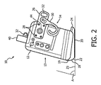
ここで図面を参照すると、同様の番号は、同じ又は類似の要素を表しており、最初に図1及び図2を参照すると、図が、一実施形態による緊急医療装置又はデバイス10を示す。これは、例えば除細動器、モニタ等、又はこれらの組み合わせといった治療デバイス12を含む。デバイス12は、複数の制御部16と、ディスプレイ面13上のタッチスクリーン対話ディスプレイ14とを含む。装置10又はデバイス12は、デバイス12の外部に取り付けることができる、又はデバイス12に一体化されることができる1つ又は複数の機械的特徴を含む。
Referring now to the drawings, wherein like numerals represent the same or similar elements, and initially referring to FIGS. 1 and 2, the figures illustrate an emergency medical device or
一実施形態では、機械的特徴は、ディスプレイ14の下のデバイス12に接続可能な基部18を含むことができる。基部18は、デバイス12の前面への接続点19を含む前部22を含む。接続点19は、スナップフィット機構、ネジ穴、リベット、磁石等、又は前部22をデバイス12に保持するための他の接続機構を含むことができる。基部18は、デバイス12に恒久的に固定されてもよく、又は一時的に取り付けられてもよい。基部18は、後部24の支持高さよりも前部22におけるより大きな支持高さを提供する。こうして、基部18は、静止面23に対して好ましくは約45度から約90度未満の角度「A」で直立構成でデバイス12を支持する。一実施形態では、角度Aは更に好ましくは、約60度から80度の間である。底部20は、静止面23に載置され、滑りを防止し、衝撃を低減又は吸収するグリップ、トレッド又は他の機械的特徴を含むことができる。基部18は、ゴム、プラスチック、金属、セラミックなどを含む材料の組み合わせを含むことができる。一実施形態では、少なくとも底部20は、ゴム又はゴム加工された表面を含む。
In one embodiment, the mechanical features can include a base 18 that can be connected to the
一実施形態では、デバイス12の基部18における機械的設計特徴は、タッチスクリーン14を静止面に対して75°の角度に位置決めする。基部18の機械的特徴、又は「足」は、各側部の前部から後部へ、及び底部20の後端部又は背部24を横切って、デバイス12の全重量を支持するための安定した基部を提供する。図2は、75°の所望のタッチスクリーン角を達成するため、静止面23における底部24の側面図を示す。底部20は、滑らかな表面における滑りを防止するためにテクスチャ加工されてもよく、好ましくは落下衝撃からの損傷を防止するのを助けるため、耐久性のある適合材料から作られる。
In one embodiment, mechanical design features at the
図2におけるタッチスクリーン14の位置は、オペレータが着座又は立っている間、改善された動作位置を提供する。そのような位置では、約60°と90°との間の角度Aが好ましい。図2は、デバイス12の側面(又は背面)に取り付けられた後部ブラケット26も示す。デバイス12の各側に一対の後部ブラケット26があり、これは、ボルト留め、リベット留め、スナップ留め、又は他の方法でデバイス12に取り付けられることができる。後部ブラケット26は、治療デバイス12の後部を横切って互いに接続されることができる。後部ブラケット26は、任意の適切な構成又は構造をとることができる。後部ブラケット26は、図3に示される位置でデバイス12を支持するため、このデバイスが後方に回転されることを可能にする衝撃吸収性の重量支持材料を含むことができる。
The position of the
図3を参照すると、デバイス12は、後部ブラケット26及び背部24が静止面と接触する第2の位置に示される。オペレータがひざまずく位置にあるときのタッチスクリーン操作のための角度位置Bは、好ましくは約0°から約30°の間である。一実施形態では、デバイス12の後部の機械的設計特徴(後部ブラケット26及び背部24)は、静止面に対して15°の角度でタッチスクリーンを位置決めする。図2に記載された第1の位置は、基部18の形状に基づき提供され、一方、図3における第2の位置は、基部18の後部ブラケット26及び背部24に基づき提供される。デバイス12の後端部をわずかに越えて延在する上述したのと同じ底面特徴部(24)(「足」)が有利に使用される。後部ブラケット26はまた、レールフック30、肩ストラップアイ(shoulder strap eye)32などの取り付け点を提供する。これらは、複数の場所に配置されることができる。後部収納又は収納ポーチのため、スペース34が提供されることができる。一緒に、背部24の後部ブラケット26は、オペレータのひざまずいている位置又はしゃがんでいる位置からデバイスを操作するための所望の15°(又は他の角度)を実現する安定した支持部を形成する。
Referring to FIG. 3,
基部18及び/又はブラケット26は、プラスチック、金属、エラストマーなどの材料を含むことができ、製造方法は、例えば、射出成形、機械加工などを含むことができる。トップハンドル40は、医療従事者又はオペレータが、片手を使用してデバイス上部を把持し、ひざまずいている間、デバイスをローアングルの操作位置(0°から30°)に押し戻すことを可能にする。代替的に、ハンドル40をつかみ、前方に引くことにより、医療従事者は、着座/立位の間、操作のための高角度操作位置(60°〜90°)にデバイス12を戻すことができる。
The
一実施形態では、後部ブラケット26は、第2の位置角度Bを変更するよう回転可能に調整されることができる。この実施形態では、ネジ28が、除去され、又は含まれないことができ、第2の位置に関する新しい角度を決定するため、ピボット44が調整されることができる。他の実施形態では、基部18は、角度Aを変更するため、つまみねじ又は他の調整機構を使用して、第1の位置の調整を提供するよう構成されることができる。更に別の実施形態では、追加的な調整を提供するため、又は例えばブラケット26若しくは基部18の後部24を更に伸ばす若しくは引っ込めるよう、装置10に関する2つより多くの設定位置を提供するため、他のブラケット又は調整が利用可能とすることができる。
In one embodiment, the
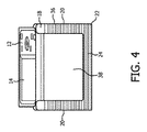
図4を参照すると、一実施形態による装置10の底面図が例示的に示される。この実施形態では、基部18の底部20は、装置10の側面及び背面に沿って「U」字形を含む。底部20は、滑りを防止するための把持機構、トレッド36又はテクスチャなどを含む。いくつかの実施形態では、スペース38は、デバイス12に接続し、支持、減衰又は追加的な構造を提供することができる他の構造又は基部特徴を含むことができる。
Referring to FIG. 4, a bottom view of the
本原理は、モニタ/除細動器に関して説明されるが、特に、2つのタイプのモニタ除細動器が、本書に記載されるマルチアングル位置決めの恩恵を受けることができる。これらは、病院内のモニタ除細動器(病院の職員により使用される)及び病院前モニタ除細動器(救急医療サービス(EMS)、公安、軍人などにより使用される)を含む。異なる操作姿勢を必要とするケア環境で使用される他の医療デバイスも、本原理の恩恵を受けることができる。 Although the present principles are described with respect to a monitor / defibrillator, in particular, two types of monitor defibrillators can benefit from the multi-angle positioning described herein. These include in-hospital monitor defibrillators (used by hospital personnel) and pre-hospital monitor defibrillators (used by emergency medical services (EMS), public security, military personnel, etc.). Other medical devices used in care environments that require different operating postures can also benefit from the present principles.
図5を参照すると、本原理による緊急医療デバイスを位置決めする方法が、例示的に示される。ブロック102において、ディスプレイ面を備える治療デバイスが提供される。治療デバイスは好ましくは、ディスプレイ面上のタッチスクリーンディスプレイと、ディスプレイのための安定したプリセットされた角度位置を設定するための機械的特徴とを含む。治療デバイスは、基部及び少なくとも1つの後部ブラケットと一体化されることができ、又は後付けされることができる。基部は、治療デバイスに結合(形成又は接続)され、前部と、静止面に載るよう構成される底部と、前部の反対側で治療デバイスの後面を越えて延在するよう構成された背部とを含む。後部ブラケット又は複数のブラケットは、治療デバイスに接続され、治療デバイスの後面を越えて延在する。底部が静止面に載っているとき、ディスプレイ面の第1の角度を提供するため、前部が背部よりも治療デバイスと異なるオフセット寸法を持つよう、基部は構成される。背部及び後部ブラケットは、背部及び少なくとも1つの後部ブラケットが、静止面に載っているとき、ディスプレイ面の第2の角度を提供する。
Referring to FIG. 5, a method for positioning an emergency medical device according to the present principles is illustratively shown. At
ブロック104において、デバイスは、例えば、静止面に対して、かつオペレータの位置に基づき、第1の角度と第2の角度との間で、その位置を変えることができる。治療デバイスは、ディスプレイ面に配置されたタッチスクリーンディスプレイを含み、第1の角度及び第2の角度は、異なる位置のユーザによる人間工学的タッチスクリーン操作を可能にする。例えば、静止面と約60度から約90度の間の第1の角度において、オペレータは、座っている又は立っているとすることができる。静止面との約0度から約30度の間の第2の角度において、オペレータは、ひざまずいているか、又はしゃがんでいるかもしれない。デバイスは、オペレータの位置に関して最適化されたプリセットされた表示角度を提供するため、有利には前後に傾けられる。 In block 104, the device can change its position between a first angle and a second angle, for example, relative to a stationary surface and based on the position of the operator. The treatment device includes a touch screen display disposed on the display surface, wherein the first angle and the second angle allow ergonomic touch screen operation by users at different locations. For example, the operator may be sitting or standing at a first angle between about 60 degrees and about 90 degrees with the stationary surface. At a second angle between about 0 degrees and about 30 degrees with the stationary surface, the operator may be kneeling or squatting. The device is advantageously tilted back and forth to provide a preset viewing angle that is optimized with respect to the operator's position.
デバイスは、このデバイスの追加的な安定した位置を支持するための他の機械的特徴を提供することにより、2つよりも多い現在の角度位置を含むことができる。ブロック106において、第1及び/又は第2の角度を調整するため、基部及び/又は後部ブラケットに対する調整が行われることができる。これは、オペレータの好み又は他の考慮事項に基づき行われることができる。 The device can include more than two current angular positions by providing other mechanical features to support the additional stable position of the device. In block 106, adjustments to the base and / or rear bracket can be made to adjust the first and / or second angles. This can be done based on operator preferences or other considerations.
ブロック108において、デバイスは、タッチスクリーンディスプレイを用いて人間工学的に操作される。タッチスクリーンディスプレイは、ユーザの位置に基づき適切に角度が付けられるので、手首及び他の腕の後方屈曲又は手首の不快感が回避される。 In block 108, the device is ergonomically operated using the touch screen display. The touch screen display is appropriately angled based on the user's position, thus avoiding wrist and other arm back flex or wrist discomfort.
添付の特許請求の範囲を解釈するにあたり、以下の点を理解されたい。
a)「有する」という語は、所与の請求項に記載される要素又は行為以外の他の要素又は行為の存在を除外するものではない。
In interpreting the appended claims, it should be understood that:
a) the word “comprising” does not exclude the presence of other elements or acts than those listed in a given claim;
b)ある要素に先行する「a」又は「an」という語は、斯かる要素が複数存在することを除外するものではない。 b) The word “a” or “an” preceding an element does not exclude the presence of a plurality of such elements.
c)請求項における任意の参照符号は、それらの範囲を制限するものではない。 c) any reference signs in the claims do not limit their scope;
d)複数の「手段」が、同じアイテム、又はハードウェア、又はソフトウェア実現による構造体、又は機能により表されることができる。 d) Multiple “means” can be represented by the same item or hardware or software implemented structure or function.
e)特に指定がない限り、行為の特定のシーケンスが必要とされること意図するものではない。 e) It is not intended that a specific sequence of actions is required unless otherwise specified.
マルチアングル位置を備えるモニタ除細動器の好ましい実施形態を説明してきたが(これは、例示であって限定することを意図するものではない)、上述の教示に照らして当業者により修正及び変更がなされ得る点に留意されたい。従って、添付の特許請求の範囲により概説される本書に開示される実施形態の範囲に含まれるものとして、本開示の特定の実施形態において変更がなされることができる点を理解されたい。こうして、本開示の内容が特許法により必要とされる範囲で詳細に記載されてきたが、特許証により保護されることを望む保護の請求は、添付の特許請求の範囲に記載される。 While preferred embodiments of monitor defibrillators with multi-angle positions have been described (this is exemplary and not intended to be limiting), modifications and changes will occur to those skilled in the art in light of the above teachings. Note that can be made. It is therefore to be understood that changes may be made in particular embodiments of the disclosure as included within the scope of embodiments disclosed herein as outlined by the appended claims. Thus, while the content of the present disclosure has been described in detail to the extent required by patent law, claims for protection that are desired to be protected by Letters Patent are set forth in the appended claims.
Claims (23)
治療デバイスを有し、前記治療デバイスが、
ディスプレイ面と、
静止面に載るよう構成される底部、及び前部の反対側で前記治療デバイスの後面を越えて延在するよう構成される背部とを含む基部と、
前記治療デバイスに接続され、前記治療デバイスの前記後面を越えて延在する後部構造体とを含み、
前記基部が、前記底部が前記静止面に載っているとき、前記ディスプレイ面の第1の角度を提供するよう構成され、
前記背部及び前記後部構造体は、前記背部及び前記後部構造体が前記静止面に載っているとき、前記ディスプレイ面の第2の角度を提供する、緊急医療デバイス。 An emergency medical device,
A treatment device, the treatment device comprising:
A display surface;
A base including a bottom configured to rest on a stationary surface and a back configured to extend beyond the rear surface of the treatment device on the opposite side of the front;
A back structure connected to the treatment device and extending beyond the back surface of the treatment device;
The base is configured to provide a first angle of the display surface when the bottom rests on the stationary surface;
The back and back structure provides an emergency medical device that provides a second angle of the display surface when the back and back structure are resting on the stationary surface.
表面に配置されたタッチスクリーンディスプレイを持つ治療デバイスと、
前記治療デバイスに結合された基部であって、
前部と、
静止面に載置される底部と、
前記治療デバイスの前記表面と反対側の前記治療デバイスの後面を越えて延在するよう構成された背部とを含む基部と、
前記治療デバイスに接続され、前記治療デバイスの前記後面を越えて延在する少なくとも1つの後部ブラケットとを有し、
前記底部が前記静止面に載っているとき前記タッチスクリーンディスプレイの第1の角度を提供するべく、前記前部が前記背部とは前記治療デバイスから異なるオフセット寸法を持つよう、前記基部が、前記タッチスクリーンディスプレイに関する少なくとも2つの観察位置を提供するよう構成され、前記背部及び前記少なくとも1つの後部ブラケットが前記静止面に載っているとき、前記背部及び前記少なくとも1つの後部ブラケットが、前記タッチスクリーンディスプレイの第2の角度を提供し、
前記緊急医療デバイスが更に、前記基部の反対の側部において前記処置デバイスに配置されるハンドルを有し、前記ハンドルが、前記少なくとも2つの観察位置の間で前記デバイスをユーザが調整することを可能にする、緊急医療デバイス。 An emergency medical device,
A treatment device having a touch screen display arranged on the surface;
A base coupled to the treatment device, comprising:
The front,
A bottom placed on a stationary surface;
A base including a back portion configured to extend beyond a rear surface of the treatment device opposite the surface of the treatment device;
At least one rear bracket connected to the treatment device and extending beyond the rear surface of the treatment device;
The base has the touch so that the front has a different offset dimension from the treatment device than the back to provide a first angle of the touch screen display when the bottom rests on the stationary surface. Configured to provide at least two viewing positions with respect to the screen display, and when the back and the at least one rear bracket rest on the stationary surface, the back and the at least one rear bracket are arranged on the touch screen display. Providing a second angle;
The emergency medical device further includes a handle disposed on the treatment device on a side opposite the base, the handle allowing a user to adjust the device between the at least two viewing positions. Make an emergency medical device.
治療デバイスを提供するステップであって、前記治療デバイスが、ディスプレイ面と、前記治療デバイスに結合された又は一体化される基部であって、前部と、静止面に載置される底部と、前記前部の反対側の前記治療デバイスの後面を越えて延在するよう構成される背部とを含む、基部と、前記治療デバイスに接続され、前記治療デバイスの前記後面を越えて延在する少なくとも1つの後部構造体であって、前記底部が前記静止面に載っているとき、前記ディスプレイ面の第1の角度を提供するべく、前記前部が前記背部とは前記治療デバイスから異なるオフセット寸法を持つよう前記基部が構成され、前記後部及び前記少なくとも1つの後部構造体が、前記静止面に載っているとき、前記ディスプレイ面の第2の角度を提供する、少なくとも1つの後部構造体とを備える、ステップと、
オペレータの位置に基づき、静止面に対して前記第1の角度及び第2の角度の間で前記デバイスの位置を変更するステップとを有する、方法。 In a method of positioning an emergency medical device,
Providing a treatment device, wherein the treatment device is a display surface, a base coupled to or integrated with the treatment device, a front portion, and a bottom mounted on a stationary surface; A base including a back configured to extend beyond a rear surface of the treatment device opposite the front and at least connected to the treatment device and extending beyond the rear surface of the treatment device A rear structure, wherein when the bottom rests on the stationary surface, the front portion has a different offset dimension from the treatment device than the back portion to provide a first angle of the display surface; The base is configured to have a second angle of the display surface when the rear and the at least one rear structure rest on the stationary surface, and less Also comprises a single rear structure, comprising the steps,
Changing the position of the device between the first angle and the second angle relative to a stationary surface based on the position of the operator.
Applications Claiming Priority (3)
| Application Number | Priority Date | Filing Date | Title |
|---|---|---|---|
| US201462090049P | 2014-12-10 | 2014-12-10 | |
| US62/090,049 | 2014-12-10 | ||
| PCT/IB2015/059395 WO2016092446A1 (en) | 2014-12-10 | 2015-12-07 | Emergency medical device positionable at two different viewing angles and a method for its positioning |
Publications (2)
| Publication Number | Publication Date |
|---|---|
| JP2017536899A true JP2017536899A (en) | 2017-12-14 |
| JP2017536899A5 JP2017536899A5 (en) | 2018-11-15 |
Family
ID=55071086
Family Applications (1)
| Application Number | Title | Priority Date | Filing Date |
|---|---|---|---|
| JP2017529012A Ceased JP2017536899A (en) | 2014-12-10 | 2015-12-07 | Emergency medical device capable of positioning at two different viewing angles and method for positioning thereof |
Country Status (6)
| Country | Link |
|---|---|
| US (1) | US20160166842A1 (en) |
| EP (1) | EP3229898B8 (en) |
| JP (1) | JP2017536899A (en) |
| CN (1) | CN107106858A (en) |
| MX (1) | MX2017007386A (en) |
| WO (1) | WO2016092446A1 (en) |
Families Citing this family (5)
| Publication number | Priority date | Publication date | Assignee | Title |
|---|---|---|---|---|
| USD847999S1 (en) * | 2017-05-23 | 2019-05-07 | Koninklijke Philips N.V. | Defibrillator monitor |
| WO2020237415A1 (en) * | 2019-05-24 | 2020-12-03 | 深圳迈瑞生物医疗电子股份有限公司 | Method for locating automated external defibrillator, and automated external defibrillator |
| FR3100441A1 (en) * | 2019-09-11 | 2021-03-12 | Air Liquide Medical Systems | Medical ventilator protected by an exoskeleton structure |
| FR3106270B1 (en) * | 2020-01-17 | 2022-01-28 | Axess Vision Tech | Medical device suitable for standing or hanging |
| CN111714777A (en) * | 2020-04-30 | 2020-09-29 | 苏州无双医疗设备有限公司 | Medical device |
Citations (3)
| Publication number | Priority date | Publication date | Assignee | Title |
|---|---|---|---|---|
| JPH11259171A (en) * | 1998-03-06 | 1999-09-24 | Toshiba Corp | Information processor |
| US7841575B1 (en) * | 2009-04-08 | 2010-11-30 | Sonosite, Inc. | Unified stand and hanging support for flat panel displays |
| US20120215284A1 (en) * | 2011-02-18 | 2012-08-23 | Medtronic, Inc. | Medical device programmer with adjustable kickstand |
Family Cites Families (5)
| Publication number | Priority date | Publication date | Assignee | Title |
|---|---|---|---|---|
| US5935152A (en) * | 1997-12-03 | 1999-08-10 | Physio-Control Manufacturing Corporation | Portable defibrillator having retractable hooks |
| US6865418B2 (en) * | 2002-03-04 | 2005-03-08 | Medtronic Physio-Control Corp. | Docking station for defibrillator |
| US20040122476A1 (en) * | 2002-12-24 | 2004-06-24 | Peter Wung | Emergency medical devices with multiple displays |
| US20070270909A1 (en) * | 2006-05-22 | 2007-11-22 | Saketkhou B Benjamin | Wireless communication device with integrated defibrillator |
| EP2978371A2 (en) * | 2013-03-27 | 2016-02-03 | Zoll Medical Corporation | Use of muscle oxygen saturation and ph in clinical decision support |
-
2015
- 2015-12-07 EP EP15820619.3A patent/EP3229898B8/en active Active
- 2015-12-07 MX MX2017007386A patent/MX2017007386A/en unknown
- 2015-12-07 WO PCT/IB2015/059395 patent/WO2016092446A1/en active Application Filing
- 2015-12-07 CN CN201580072576.1A patent/CN107106858A/en active Pending
- 2015-12-07 JP JP2017529012A patent/JP2017536899A/en not_active Ceased
- 2015-12-10 US US14/965,065 patent/US20160166842A1/en not_active Abandoned
Patent Citations (3)
| Publication number | Priority date | Publication date | Assignee | Title |
|---|---|---|---|---|
| JPH11259171A (en) * | 1998-03-06 | 1999-09-24 | Toshiba Corp | Information processor |
| US7841575B1 (en) * | 2009-04-08 | 2010-11-30 | Sonosite, Inc. | Unified stand and hanging support for flat panel displays |
| US20120215284A1 (en) * | 2011-02-18 | 2012-08-23 | Medtronic, Inc. | Medical device programmer with adjustable kickstand |
Also Published As
| Publication number | Publication date |
|---|---|
| CN107106858A (en) | 2017-08-29 |
| MX2017007386A (en) | 2017-10-20 |
| EP3229898A1 (en) | 2017-10-18 |
| WO2016092446A1 (en) | 2016-06-16 |
| EP3229898B1 (en) | 2020-02-12 |
| EP3229898B8 (en) | 2020-04-01 |
| US20160166842A1 (en) | 2016-06-16 |
Similar Documents
| Publication | Publication Date | Title |
|---|---|---|
| JP2017536899A (en) | Emergency medical device capable of positioning at two different viewing angles and method for positioning thereof | |
| ES2796798T3 (en) | Auxiliary cart | |
| US10314750B2 (en) | Sliding arm mechanism for wheelchairs | |
| US8191487B2 (en) | Wall-mounted accessory holder | |
| US20180279992A1 (en) | Positioning device and method of use | |
| JP2019528838A (en) | User console system for robotic surgery | |
| US8931744B1 (en) | Shopping cart support | |
| US20170273454A1 (en) | Ergonomic keyboard and peripheral positioning system | |
| US20090145336A1 (en) | Computer Tables | |
| US8938888B1 (en) | Hair drying system | |
| JP2017536899A5 (en) | ||
| US20170303680A1 (en) | Work surface arrangement | |
| Shaik | Dental ergonomics: Basic steps to enhance work efficiency | |
| US20080022448A1 (en) | Bathing aid | |
| US20170265643A1 (en) | Ergonomic fully adjustable work station | |
| KR101366637B1 (en) | Walking support device | |
| CN104279414A (en) | Portable mobile equipment bracket for hospitalized patient | |
| RU2664225C1 (en) | Personal workplace of the user limited in movements (options) | |
| US6745986B1 (en) | Support apparatus and method | |
| US11559454B2 (en) | Rotational support apparatus | |
| Shachshanova et al. | Workplace ergonomics is an important aspect of human-computer interaction and human health | |
| US20100106067A1 (en) | Portable resetting device | |
| Dropkin | 3. ERGONOMICS: Computer Workstations | |
| KR20170050967A (en) | Wheelchair | |
| JP2000152845A (en) | Chair |
Legal Events
| Date | Code | Title | Description |
|---|---|---|---|
| A521 | Request for written amendment filed |
Free format text: JAPANESE INTERMEDIATE CODE: A523 Effective date: 20181005 |
|
| A621 | Written request for application examination |
Free format text: JAPANESE INTERMEDIATE CODE: A621 Effective date: 20181005 |
|
| A977 | Report on retrieval |
Free format text: JAPANESE INTERMEDIATE CODE: A971007 Effective date: 20190807 |
|
| A131 | Notification of reasons for refusal |
Free format text: JAPANESE INTERMEDIATE CODE: A131 Effective date: 20190820 |
|
| A521 | Request for written amendment filed |
Free format text: JAPANESE INTERMEDIATE CODE: A523 Effective date: 20191108 |
|
| A131 | Notification of reasons for refusal |
Free format text: JAPANESE INTERMEDIATE CODE: A131 Effective date: 20200204 |
|
| A601 | Written request for extension of time |
Free format text: JAPANESE INTERMEDIATE CODE: A601 Effective date: 20200427 |
|
| A02 | Decision of refusal |
Free format text: JAPANESE INTERMEDIATE CODE: A02 Effective date: 20201006 |
|
| A521 | Request for written amendment filed |
Free format text: JAPANESE INTERMEDIATE CODE: A523 Effective date: 20210121 |
|
| C60 | Trial request (containing other claim documents, opposition documents) |
Free format text: JAPANESE INTERMEDIATE CODE: C60 Effective date: 20210121 |
|
| A911 | Transfer to examiner for re-examination before appeal (zenchi) |
Free format text: JAPANESE INTERMEDIATE CODE: A911 Effective date: 20210127 |
|
| C21 | Notice of transfer of a case for reconsideration by examiners before appeal proceedings |
Free format text: JAPANESE INTERMEDIATE CODE: C21 Effective date: 20210128 |
|
| A912 | Re-examination (zenchi) completed and case transferred to appeal board |
Free format text: JAPANESE INTERMEDIATE CODE: A912 Effective date: 20210319 |
|
| C211 | Notice of termination of reconsideration by examiners before appeal proceedings |
Free format text: JAPANESE INTERMEDIATE CODE: C211 Effective date: 20210323 |
|
| C22 | Notice of designation (change) of administrative judge |
Free format text: JAPANESE INTERMEDIATE CODE: C22 Effective date: 20210708 |
|
| C23 | Notice of termination of proceedings |
Free format text: JAPANESE INTERMEDIATE CODE: C23 Effective date: 20210902 |
|
| C03 | Trial/appeal decision taken |
Free format text: JAPANESE INTERMEDIATE CODE: C03 Effective date: 20210930 |
|
| C30A | Notification sent |
Free format text: JAPANESE INTERMEDIATE CODE: C3012 Effective date: 20210930 |
|
| A045 | Written measure of dismissal of application [lapsed due to lack of payment] |
Free format text: JAPANESE INTERMEDIATE CODE: A045 Effective date: 20220120 |