JP2017536266A - Desktop printing apparatus and duplex printing module for 3D printing of objects - Google Patents
Desktop printing apparatus and duplex printing module for 3D printing of objects Download PDFInfo
- Publication number
- JP2017536266A JP2017536266A JP2017524458A JP2017524458A JP2017536266A JP 2017536266 A JP2017536266 A JP 2017536266A JP 2017524458 A JP2017524458 A JP 2017524458A JP 2017524458 A JP2017524458 A JP 2017524458A JP 2017536266 A JP2017536266 A JP 2017536266A
- Authority
- JP
- Japan
- Prior art keywords
- medium
- module
- printing
- media
- Prior art date
- Legal status (The legal status is an assumption and is not a legal conclusion. Google has not performed a legal analysis and makes no representation as to the accuracy of the status listed.)
- Pending
Links
Images


Classifications
-
- B—PERFORMING OPERATIONS; TRANSPORTING
- B29—WORKING OF PLASTICS; WORKING OF SUBSTANCES IN A PLASTIC STATE IN GENERAL
- B29C—SHAPING OR JOINING OF PLASTICS; SHAPING OF MATERIAL IN A PLASTIC STATE, NOT OTHERWISE PROVIDED FOR; AFTER-TREATMENT OF THE SHAPED PRODUCTS, e.g. REPAIRING
- B29C64/00—Additive manufacturing, i.e. manufacturing of three-dimensional [3D] objects by additive deposition, additive agglomeration or additive layering, e.g. by 3D printing, stereolithography or selective laser sintering
- B29C64/20—Apparatus for additive manufacturing; Details thereof or accessories therefor
-
- B—PERFORMING OPERATIONS; TRANSPORTING
- B29—WORKING OF PLASTICS; WORKING OF SUBSTANCES IN A PLASTIC STATE IN GENERAL
- B29C—SHAPING OR JOINING OF PLASTICS; SHAPING OF MATERIAL IN A PLASTIC STATE, NOT OTHERWISE PROVIDED FOR; AFTER-TREATMENT OF THE SHAPED PRODUCTS, e.g. REPAIRING
- B29C64/00—Additive manufacturing, i.e. manufacturing of three-dimensional [3D] objects by additive deposition, additive agglomeration or additive layering, e.g. by 3D printing, stereolithography or selective laser sintering
- B29C64/30—Auxiliary operations or equipment
- B29C64/307—Handling of material to be used in additive manufacturing
- B29C64/321—Feeding
-
- B—PERFORMING OPERATIONS; TRANSPORTING
- B29—WORKING OF PLASTICS; WORKING OF SUBSTANCES IN A PLASTIC STATE IN GENERAL
- B29C—SHAPING OR JOINING OF PLASTICS; SHAPING OF MATERIAL IN A PLASTIC STATE, NOT OTHERWISE PROVIDED FOR; AFTER-TREATMENT OF THE SHAPED PRODUCTS, e.g. REPAIRING
- B29C64/00—Additive manufacturing, i.e. manufacturing of three-dimensional [3D] objects by additive deposition, additive agglomeration or additive layering, e.g. by 3D printing, stereolithography or selective laser sintering
- B29C64/10—Processes of additive manufacturing
- B29C64/141—Processes of additive manufacturing using only solid materials
- B29C64/147—Processes of additive manufacturing using only solid materials using sheet material, e.g. laminated object manufacturing [LOM] or laminating sheet material precut to local cross sections of the 3D object
-
- B—PERFORMING OPERATIONS; TRANSPORTING
- B29—WORKING OF PLASTICS; WORKING OF SUBSTANCES IN A PLASTIC STATE IN GENERAL
- B29C—SHAPING OR JOINING OF PLASTICS; SHAPING OF MATERIAL IN A PLASTIC STATE, NOT OTHERWISE PROVIDED FOR; AFTER-TREATMENT OF THE SHAPED PRODUCTS, e.g. REPAIRING
- B29C64/00—Additive manufacturing, i.e. manufacturing of three-dimensional [3D] objects by additive deposition, additive agglomeration or additive layering, e.g. by 3D printing, stereolithography or selective laser sintering
- B29C64/30—Auxiliary operations or equipment
- B29C64/386—Data acquisition or data processing for additive manufacturing
- B29C64/393—Data acquisition or data processing for additive manufacturing for controlling or regulating additive manufacturing processes
-
- B—PERFORMING OPERATIONS; TRANSPORTING
- B33—ADDITIVE MANUFACTURING TECHNOLOGY
- B33Y—ADDITIVE MANUFACTURING, i.e. MANUFACTURING OF THREE-DIMENSIONAL [3-D] OBJECTS BY ADDITIVE DEPOSITION, ADDITIVE AGGLOMERATION OR ADDITIVE LAYERING, e.g. BY 3-D PRINTING, STEREOLITHOGRAPHY OR SELECTIVE LASER SINTERING
- B33Y10/00—Processes of additive manufacturing
-
- B—PERFORMING OPERATIONS; TRANSPORTING
- B33—ADDITIVE MANUFACTURING TECHNOLOGY
- B33Y—ADDITIVE MANUFACTURING, i.e. MANUFACTURING OF THREE-DIMENSIONAL [3-D] OBJECTS BY ADDITIVE DEPOSITION, ADDITIVE AGGLOMERATION OR ADDITIVE LAYERING, e.g. BY 3-D PRINTING, STEREOLITHOGRAPHY OR SELECTIVE LASER SINTERING
- B33Y30/00—Apparatus for additive manufacturing; Details thereof or accessories therefor
-
- B—PERFORMING OPERATIONS; TRANSPORTING
- B33—ADDITIVE MANUFACTURING TECHNOLOGY
- B33Y—ADDITIVE MANUFACTURING, i.e. MANUFACTURING OF THREE-DIMENSIONAL [3-D] OBJECTS BY ADDITIVE DEPOSITION, ADDITIVE AGGLOMERATION OR ADDITIVE LAYERING, e.g. BY 3-D PRINTING, STEREOLITHOGRAPHY OR SELECTIVE LASER SINTERING
- B33Y40/00—Auxiliary operations or equipment, e.g. for material handling
-
- B—PERFORMING OPERATIONS; TRANSPORTING
- B41—PRINTING; LINING MACHINES; TYPEWRITERS; STAMPS
- B41J—TYPEWRITERS; SELECTIVE PRINTING MECHANISMS, i.e. MECHANISMS PRINTING OTHERWISE THAN FROM A FORME; CORRECTION OF TYPOGRAPHICAL ERRORS
- B41J11/00—Devices or arrangements of selective printing mechanisms, e.g. ink-jet printers or thermal printers, for supporting or handling copy material in sheet or web form
- B41J11/008—Controlling printhead for accurately positioning print image on printing material, e.g. with the intention to control the width of margins
-
- B—PERFORMING OPERATIONS; TRANSPORTING
- B41—PRINTING; LINING MACHINES; TYPEWRITERS; STAMPS
- B41J—TYPEWRITERS; SELECTIVE PRINTING MECHANISMS, i.e. MECHANISMS PRINTING OTHERWISE THAN FROM A FORME; CORRECTION OF TYPOGRAPHICAL ERRORS
- B41J15/00—Devices or arrangements of selective printing mechanisms, e.g. ink-jet printers or thermal printers, specially adapted for supporting or handling copy material in continuous form, e.g. webs
- B41J15/04—Supporting, feeding, or guiding devices; Mountings for web rolls or spindles
- B41J15/042—Supporting, feeding, or guiding devices; Mountings for web rolls or spindles for loading rolled-up continuous copy material into printers, e.g. for replacing a used-up paper roll; Point-of-sale printers with openable casings allowing access to the rolled-up continuous copy material
-
- B—PERFORMING OPERATIONS; TRANSPORTING
- B41—PRINTING; LINING MACHINES; TYPEWRITERS; STAMPS
- B41J—TYPEWRITERS; SELECTIVE PRINTING MECHANISMS, i.e. MECHANISMS PRINTING OTHERWISE THAN FROM A FORME; CORRECTION OF TYPOGRAPHICAL ERRORS
- B41J15/00—Devices or arrangements of selective printing mechanisms, e.g. ink-jet printers or thermal printers, specially adapted for supporting or handling copy material in continuous form, e.g. webs
- B41J15/16—Means for tensioning or winding the web
-
- B—PERFORMING OPERATIONS; TRANSPORTING
- B41—PRINTING; LINING MACHINES; TYPEWRITERS; STAMPS
- B41J—TYPEWRITERS; SELECTIVE PRINTING MECHANISMS, i.e. MECHANISMS PRINTING OTHERWISE THAN FROM A FORME; CORRECTION OF TYPOGRAPHICAL ERRORS
- B41J2/00—Typewriters or selective printing mechanisms characterised by the printing or marking process for which they are designed
- B41J2/005—Typewriters or selective printing mechanisms characterised by the printing or marking process for which they are designed characterised by bringing liquid or particles selectively into contact with a printing material
- B41J2/01—Ink jet
-
- B—PERFORMING OPERATIONS; TRANSPORTING
- B41—PRINTING; LINING MACHINES; TYPEWRITERS; STAMPS
- B41J—TYPEWRITERS; SELECTIVE PRINTING MECHANISMS, i.e. MECHANISMS PRINTING OTHERWISE THAN FROM A FORME; CORRECTION OF TYPOGRAPHICAL ERRORS
- B41J3/00—Typewriters or selective printing or marking mechanisms characterised by the purpose for which they are constructed
- B41J3/60—Typewriters or selective printing or marking mechanisms characterised by the purpose for which they are constructed for printing on both faces of the printing material
-
- B—PERFORMING OPERATIONS; TRANSPORTING
- B65—CONVEYING; PACKING; STORING; HANDLING THIN OR FILAMENTARY MATERIAL
- B65H—HANDLING THIN OR FILAMENTARY MATERIAL, e.g. SHEETS, WEBS, CABLES
- B65H23/00—Registering, tensioning, smoothing or guiding webs
- B65H23/04—Registering, tensioning, smoothing or guiding webs longitudinally
- B65H23/32—Arrangements for turning or reversing webs
Abstract
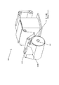
デスクトッププリント装置(100)は、オブジェクトを3-Dプリントし、単一ハウジングに一列に設けられたプリントモジュール(200)及びビルドモジュール(300)を備える。プリントモジュールは、媒体(500)の一部をプリントしてオブジェクトの媒体層(701)を画定する1以上のプリントヘッド(230, 230')を備える。ビルドモジュールは、複数の媒体層から3Dオブジェクトを組み上げるため、ビルドプレート(310)、カット手段(321)、接合手段及び接着剤分注手段(320)を備える。装置は更に、媒体入力部と媒体出力部との間でハウジングに画定される媒体搬送通路と、媒体入力部から、媒体搬送通路に沿ってプリント用のプリントモジュールを通って、また引き続き、オブジェクトの媒体層を画定するためのプロファイリング及び接合用のビルドモジュールに媒体を連続的に搬送するための搬送手段(160)と、を備えている。【選択図】図18The desktop printing apparatus (100) includes a print module (200) and a build module (300) that 3-D prints an object and is arranged in a single housing. The print module includes one or more printheads (230, 230 ′) that print a portion of the media (500) to define the media layer (701) of the object. The build module includes a build plate (310), a cutting means (321), a joining means, and an adhesive dispensing means (320) for assembling a 3D object from a plurality of media layers. The apparatus further includes a media transport path defined in the housing between the media input section and the media output section, from the media input section, through the print module for printing along the media transport path, and subsequently to the object. Transport means (160) for continuously transporting the media to the build module for profiling and joining for defining the media layer. [Selection] Figure 18
Description
本出願の発明(以下「本発明」と称する)は、ラピッドプロトタイピング(PR)のための積層オブジェクト製造法(Layered Object Manufacture:LOM)システムに関するものであり、そして特に、従来の2Dプリントと3Dプリントとを統合して、LOMシステムで3Dオブジェクトを形成するためのデスクトップ装置に関する。 The invention of the present application (hereinafter referred to as “the present invention”) relates to a Layered Object Manufacture (LOM) system for rapid prototyping (PR), and in particular, conventional 2D printing and 3D. The present invention relates to a desktop device for integrating a print and forming a 3D object in a LOM system.
ラピッドプロトタイピングは、当該ラピッドプロトタイピングにおいて、オブジェクトが、材料の除去又は減法に依存する従来の機械加工法ではなく、材料の付加によって成形することができる点でコンピュータ制御された加法的作製方法として定義される。「ラピッド(高速)」という用語は、使用される方法、並びにモデルの寸法及び複雑さに依存して、完成した三次元物品の作成には数時間から数日かかることがあり得るため、この技術分野では特別の意味を有すると、理解されたい。ラピッドプロトタイピングの一般的な技術分野で採用されている多くの既知の方法がある。積層オブジェクト製造法(Layered Object Manufacture:LOM)は、ラピッドプロトタイピング(RP)の一形態であり、接着剤コーティングされた、紙、プラスチック又は金属のラミネートを順次に積層し、このときラミネートは順次に互いに接着され、またナイフ又はレーザーカッタで整形カットする順次積層に関する。 Rapid prototyping is a computer-controlled additive fabrication method in that rapid prototyping allows objects to be shaped by the addition of material rather than traditional machining methods that rely on material removal or subtraction. Defined. The term “rapid” is a technique that can take hours to days to create a finished 3D article, depending on the method used and the size and complexity of the model. It should be understood that it has a special meaning in the field. There are many known methods employed in the general technical field of rapid prototyping. Layered Object Manufacture (LOM) is a form of rapid prototyping (RP), in which adhesive-coated, paper, plastic or metal laminates are laminated sequentially, The present invention relates to sequential lamination which is bonded to each other and shaped and cut with a knife or a laser cutter.
LOMは、他のラピッドプロトタイピングと同様、慣習的に、オブジェクト/パーツの製造に三次元(3D)コンピュータ支援設計(CAD)の使用を含み、当該3DCADから、CADパッケージ内でステレオリソグラフィ(STL) ファイル又は他の適当なフォーマットファイルが作成される。前記STLファイルが処理され、実際には、使用される基板材料の厚さと一致する厚さでZ軸方向に仮想的にスライスされる。このことは、前記パーツの一連の断面を形作り、また、任意な特定の高さにおいても、各パーツは、単純な二次元(2D)プロファイルを有している。プロファイリング又はカッティングのため、装置を使用して2Dプロファイルをトレースし、またこれに従って原材料の薄いシートに対してその形状をカットすることができる。LOMでは、完全な3Dオブジェクトを製造するために、個々の薄いシートそれぞれは、他方の上部に積み重ねられ、そして、接合させることができる。複数の媒体オブジェクト層が形成された後、プロファイリング処理及び層接合処理が実行される。複数の層が一体に接合され、そして、その後プリントされた前記媒体のスタックから不用な支持材料を除去するステップを備える、プロファイリング又はウィーディング(刈込み)処理が実行され、3Dプリントオブジェクトが現れる。プロファイリング処理、スタッキング処理及び接合処理の順序は、入れ替えることができる。前記個別層は、従来の2Dプリント処理を使用してプリントすることもできる。前記層は、片面プリントされ又は両面プリントされてもよく、また、黒インクのような単色でプリントされても、又は、複数の色でカラープリントされてもよい。さらに、多色紙を使用し得る。 LOM, like other rapid prototyping, conventionally includes the use of three-dimensional (3D) computer-aided design (CAD) in object / part manufacturing, and from that 3D CAD into stereo lithography (STL) within the CAD package. A file or other suitable format file is created. The STL file is processed and is actually virtually sliced in the Z-axis direction with a thickness that matches the thickness of the substrate material used. This forms a series of cross-sections of the part, and at any particular height, each part has a simple two-dimensional (2D) profile. For profiling or cutting, the device can be used to trace a 2D profile and cut its shape accordingly for a thin sheet of raw material. In LOM, in order to produce a complete 3D object, each individual thin sheet can be stacked on top of the other and joined. After the plurality of media object layers are formed, a profiling process and a layer joining process are performed. A plurality of layers are joined together and then a profiling or weeding process is performed comprising removing unwanted support material from the printed stack of media to reveal a 3D print object. The order of the profiling process, stacking process, and joining process can be interchanged. The individual layers can also be printed using a conventional 2D printing process. The layer may be printed on one side or double side, and may be printed with a single color such as black ink, or may be color printed with multiple colors. In addition, multicolor paper can be used.
LOM製造法では、一般的に、完成した3Dオブジェクトは、所望する最終的な幾何学形状を形成するために、組み付けられ、またプロファイリングされた、個別媒体層のスタックから形成される。前記個別媒体層は、前記組み付け構成の前に、プリント又は他の処理がなされるものとし得る。従って、複数の3Dオブジェクト媒体層は、完成した3Dプリント物品を形成するための準備段階で、プリントされていてもよい。3Dプリントされた物品用の、積層スタック全体は、プリントモジュールにおけるオフラインで予めプリントすることができ、その後、プリントされたスタックを、プロファイリング及び層接合モジュールに装填することができ、当該モジュールにおいて、プリントされた各層は、3Dプリントされた物品の作製を終了するように、プロファイリングされ、また接合することができる。 In a LOM manufacturing process, a completed 3D object is typically formed from a stack of individual media layers that are assembled and profiled to form the desired final geometry. The individual media layer may be printed or otherwise processed prior to the assembly configuration. Accordingly, the plurality of 3D object media layers may be printed in a preparation stage for forming a finished 3D printed article. The entire laminate stack for a 3D printed article can be pre-printed off-line in a print module, and then the printed stack can be loaded into a profiling and layer bonding module where the print Each of the layers can be profiled and bonded to complete the production of the 3D printed article.
最終的な3Dオブジェクトに丁合及び組み付けるための準備において、プリントされた前記媒体層の両側の側面にプリントされた画像のアラインメント(整列)に関して問題が生じる可能性がある。プリントされた前記シートが3Dプリンタに入力されるときに正しい順序で提供されない場合、問題が生じる可能性もある。 In preparation for collating and assembling to the final 3D object, problems can arise with respect to the alignment of images printed on both sides of the printed media layer. Problems can also arise if the printed sheets are not provided in the correct order when they are input to a 3D printer.
あるプリンタは、パーツをカラーで製造するために使用することができる。ある1つの手法では、例えば、着色されたシートを使用することができる。別の手法では、例えば、紙の各シートに着色されたインクをプリントすることができ、又は、各シートに画像をプリントすることができ、そして、その後、プリントされた前記シートを、カット及び接着が行われるプリンタの部分に装填することができる。 Some printers can be used to produce parts in color. In one approach, for example, a colored sheet can be used. In another approach, for example, colored ink can be printed on each sheet of paper, or an image can be printed on each sheet, and the printed sheet can then be cut and glued Can be loaded into the part of the printer where
着色されたシート及び/又はインクの使用並びに画像のプリントは、3Dプリンタマシン及び/又は処理に、更なる複雑さを加えるであろうことは理解されるであろう。 It will be appreciated that the use of colored sheets and / or ink and the printing of images will add further complexity to the 3D printer machine and / or processing.
3Dプリントマシンを選択するときの検討事項には、速度、3Dプリンタのコスト、プリントされたプロトタイプのコスト、そして、材料のコスト及び選択、また、カラー機能が含まれる。多くの場合、3Dプリントのコストは高すぎて、民生用アプリケーションとしてはほとんど実用的ではない。更に、多くの場合、現在利用可能な3Dプリンタは、民生用アプリケーションとしては大きすぎる。 Considerations when selecting a 3D printing machine include speed, 3D printer cost, printed prototype cost, material cost and selection, and color capabilities. In many cases, the cost of 3D printing is too high and is hardly practical for consumer applications. Furthermore, in many cases, currently available 3D printers are too large for consumer applications.
紙の使用は、SDL又はLOMにおいて、原材料のコストを削減するが、プリンタのサイズ及び複雑さという問題が依然として残り、そして、より安価に製造することができ、また個人向けの家庭用デスクトップに適している、よりコンパクトで複雑でないプリンタを開発する必要がある。 The use of paper reduces the cost of raw materials in SDL or LOM, but the problem of printer size and complexity still remains and can be manufactured cheaper and is suitable for personal home desktops There is a need to develop a more compact and less complex printer.
従って、3Dプリント処理に関しては、対処の必要があるラピッドプロトタイピング用のLOMシステムにおいて多くの問題がある。本発明は、LOMによって着色されたオブジェクトを製造するための、改良された方法を提供することを目的とする。本明細書記載の発明(以下「本発明」と称する)は、また、改良された3Dプリントシステムを提供することを目的とする。 Therefore, there are a number of problems associated with 3D printing processes in rapid prototyping LOM systems that need to be addressed. The present invention seeks to provide an improved method for producing objects colored by LOM. The invention described herein (hereinafter referred to as “the present invention”) also aims to provide an improved 3D printing system.
本発明によれば、オブジェクトを3Dプリントするためのデスクトッププリント装置が提供され、当該デスクトッププリント装置は、3Dオブジェクトを複数の媒体層から組み上げるためのビルドモジュールを備えており、前記装置は、更に、プリントされた前記媒体が前記オブジェクトの媒体層を画定するよう、前記媒体をプリントするためのプリントモジュールと、前記媒体を、入力部から、前記媒体層をプリントするための前記プリントモジュールに連続的に搬送するように、また前記プリントされた媒体層を前記ビルドモジュールに搬送するように構成された搬送手段と、を備えている。 According to the present invention, a desktop printing apparatus for 3D printing an object is provided, the desktop printing apparatus comprising a build module for assembling a 3D object from a plurality of media layers, the apparatus further comprising: A print module for printing the medium, and the medium from an input to the print module for printing the media layer, such that the printed medium defines a media layer of the object; Conveying means configured to convey and to convey the printed media layer to the build module.
ある1つの構成では、前記ビルドモジュールは、前記3Dオブジェクトを組み上げるために、接着剤供給手段、カット手段及び接合手段を備えている。 In one configuration, the build module includes an adhesive supply means, a cutting means, and a joining means for assembling the 3D object.
ある1つの構成では、前記ビルドモジュールは、選択的堆積ラミネーション(selective deposition lamination:SDL)によって、3Dオブジェクトを製造するように構成されている。 In one configuration, the build module is configured to produce a 3D object by selective deposition lamination (SDL).
ある1つの構成では、前記プリントモジュール及び前記ビルドモジュールは、単一の一体型装置内に一列に配置されており、また、前記搬送手段は、連続インライン搬送動作で、前記媒体を、入力部から前記プリントモジュールに、また前記ビルドモジュールに搬送するように構成されている。 In one configuration, the print module and the build module are arranged in a single unit in a single integrated apparatus, and the transport means is a continuous in-line transport operation, and the medium is transferred from the input unit. It is configured to be transported to the print module and to the build module.
ある1つの構成では、前記プリントモジュール及び前記ビルドモジュールは、前記搬送手段が前記装置を通して前記媒体を搬送するときに、同時に動作するように構成されている。 In one configuration, the print module and the build module are configured to operate simultaneously when the transport means transports the medium through the apparatus.
ある1つの構成では、前記プリントモジュール及び前記ビルドモジュールは、前記搬送手段が前記装置を通して前記媒体を搬送するときに、独立して動作する。 In one configuration, the print module and the build module operate independently when the transport means transports the medium through the apparatus.
ある1つの構成では、前記プリントモジュールは、前記媒体の、片面プリント用又は両面プリント用に構成されている。 In one configuration, the print module is configured for single-sided printing or double-sided printing of the medium.
ある1つの構成では、前記プリントモジュールは、前記媒体の両面プリント用に構成されており、前記オブジェクトの、プリントされた媒体層を画定するために、媒体層にプリントされる画像対の第1画像が前記媒体の第1側面にプリントされ、また前記画像対の第2画像が、前記第1画像に背中合わせとなるよう前記媒体の前記第2側面にプリントされる。 In one configuration, the print module is configured for double-sided printing of the media, and a first image of an image pair printed on a media layer to define a printed media layer of the object. Are printed on the first side of the medium, and the second image of the image pair is printed on the second side of the medium so as to be back-to-back with the first image.
ある1つの構成では、前記プリントモジュールは、更に、媒体の第1側面に基準マークをプリントするように構成されており、前記基準マークは、前記媒体の第1側面にプリントされた前記画像についての情報を提供するように構成されたマーク、例えば、ロケータマーク、又はプリント用の一連の前記画像から当該画像を識別するための画像識別子を有する。 In one configuration, the print module is further configured to print a fiducial mark on a first side of the media, the fiducial mark being about the image printed on the first side of the media. A mark configured to provide information, for example, a locator mark, or an image identifier for identifying the image from the series of images for printing.
ある1つの構成では、前記装置は、更に、前記媒体の第1側面にプリントされた、画像又は前記画像の一部又は基準マークを感知するための感知手段を備えており、また前記感知手段は、前記第1画像に背中合わせとなるよう前記媒体の第2側面における第2画像のプリントを制御するために、前記媒体の位置を制御する出力をコントローラに供給する。 In one configuration, the apparatus further comprises sensing means for sensing an image or part of the image or fiducial mark printed on the first side of the medium, and the sensing means In order to control the printing of the second image on the second side of the medium so as to be back to back with the first image, an output for controlling the position of the medium is supplied to the controller.
ある1つの構成では、前記コントローラは、任意の検出されたスキュー又は位置エラーを補正するために、前記装置を制御するように構成されている。 In one configuration, the controller is configured to control the device to correct any detected skew or position error.
ある1つの構成では、前記搬送手段は、送りローラ及び/又は駆動又はピンチローラ又はニップローラ及び/又はガイド手段を備えている。 In one configuration, the conveying means comprises a feed roller and / or drive or pinch roller or nip roller and / or guide means.
ある1つの構成では、前記搬送手段は、更に、前記媒体が前記装置を通過して搬送され、また、前記プリントモジュール及び前記ビルドモジュールを通過して搬送されるときに、前記媒体の張力を維持するためのテイクアップローラを備えている。 In one configuration, the transport means further maintains the tension of the medium when the medium is transported through the apparatus and transported through the print module and the build module. A take-up roller is provided.
ある1つの構成では、前記搬送手段は、第1ステーション及び第2ステーションを備えており、プリントヘッドが、前記第1ステーションで前記媒体の前記第1側面に画像をプリントし、また、前記第2ステーションで前記媒体の前記第2側面に画像をプリントするように構成されている。 In one configuration, the transport means includes a first station and a second station, and a print head prints an image on the first side of the medium at the first station, and the second station The station is configured to print an image on the second side of the medium.
ある1つの構成では、前記搬送手段は、媒体搬送パスを画定し、この媒体搬送パスにおいて、前記媒体は、前記入力部から前記プリントモジュールを通過して、そして前記ビルドモジュールに搬送される。 In one configuration, the transport means defines a medium transport path, in which the medium passes from the input unit through the print module and is transported to the build module.
ある1つの構成では、前記第1プリントステーション及び前記第2プリントステーションは、前記搬送パスに沿って間隔を置いて配置されている。 In one configuration, the first print station and the second print station are spaced along the transport path.
ある1つの構成では、前記プリントヘッドは、前記媒体の第1側面及び第2側面をプリントするために、前記第1プリントステーションと前記第2プリントステーションとの間を移動可能である。 In one configuration, the print head is movable between the first print station and the second print station to print the first side and the second side of the media.
ある1つの構成では、前記搬送手段は、前記媒体が前記第1プリントステーションから前記第2プリントステーションに搬送されるときに、前記媒体を反転させるように構成されている。 In one configuration, the transport means is configured to invert the medium when the medium is transported from the first print station to the second print station.
ある1つの構成では、前記装置は、単一のプリントヘッドを備えている。 In one configuration, the device comprises a single printhead.
ある1つの構成では、前記第1プリントステーションは、前記媒体を第1の向きにプリントするように構成され、前記第2プリントステーションは、前記媒体を第2の向きにプリントするように構成されている。 In one configuration, the first print station is configured to print the media in a first orientation, and the second print station is configured to print the media in a second orientation. Yes.
ある1つの構成では、前記搬送手段は、連続ロールの形態で前記媒体を受け入れるための容器を備えている。 In one configuration, the transport means comprises a container for receiving the medium in the form of a continuous roll.
ある1つの構成では、前記装置は、第1プリントステーション及び第2プリントステーションで、前記媒体の第1表面及び第2表面に同時にプリントするための、第1プリントヘッド及び第2プリントヘッドを備えている。 In one configuration, the apparatus comprises a first print head and a second print head for simultaneously printing on a first surface and a second surface of the medium at a first print station and a second print station. Yes.
ある1つの構成では、本発明は、上述のような3Dプリント装置を提供し、前記両面プリントモジュール及び前記ビルドモジュールは、単一の一体型装置内に設けられており、また前記搬送手段は、前記媒体を、入力部から前記プリントモジュールを経由して、3Dオブジェクトを連続インライン処理で形成する組み付けを行う前記ビルドモジュールまで搬送するように構成されている。 In one configuration, the present invention provides a 3D printing apparatus as described above, wherein the duplex printing module and the build module are provided in a single integrated apparatus, and the conveying means includes: The medium is transported from the input unit via the print module to the build module that performs assembling to form a 3D object by continuous inline processing.
他の構成では、3Dプリント装置用の両面プリントモジュールが提供され、当該両面プリントモジュールは、プリント手段及び搬送手段を備えており、前記搬送手段は、媒体を、入力部から、第1側面及び第2側面に前記媒体のプリントを行うための前記プリント手段に搬送し、前記媒体にプリントすべき画像対の第1画像が、前記媒体の第1側面にプリントされ、また前記画像対の第2画像が、前記第1画像に背中合わせとなるよう前記媒体の第2側面にプリントされるようにする。 In another configuration, a double-sided print module for a 3D printing apparatus is provided, and the double-sided print module includes a printing unit and a conveyance unit, and the conveyance unit receives a medium from an input unit, a first side surface, and a A first image of an image pair to be conveyed to the printing means for printing the medium on two sides and to be printed on the medium is printed on a first side of the medium, and a second image of the image pair; Is printed on the second side of the medium so as to be back-to-back with the first image.
ある1つの構成では、前記プリントされた画像対は、3Dオブジェクトのプリントされた媒体層を画定する。 In one configuration, the printed image pair defines a printed media layer of a 3D object.
ある1つの構成では、前記プリントヘッドは、前記媒体層の平面に対してX方向及びY方向に移動するように構成されている。 In one configuration, the print head is configured to move in the X and Y directions relative to the plane of the media layer.
ある1つの構成では、前記モジュールは、画像を前記媒体の第1側面にプリントし、また、マシン可読位置ロケータを前記媒体の前記第1側面にプリントするように構成されたプリントヘッドと、前記マシン可読位置ロケータを読み取って、また前記媒体の第2側面に対する前記媒体又は前記プリントヘッドの位置に変化をもたらすように構成され、前記第1側面に設けられた前記プリントされた画像に対する、前記第2側に設けるべき画像の適正アラインメントを確保する、光学式読取機と、を備えている。 In one configuration, the module prints an image on a first side of the media and prints a machine-readable position locator on the first side of the media; and the machine Reading the readable position locator and also causing a change in the position of the medium or the print head relative to the second side of the medium, the second for the printed image provided on the first side And an optical reader for ensuring proper alignment of images to be provided on the side.
本発明の態様によれば、オブジェクトを3−Dプリントするためのデスクトッププリント装置が提供され、当該デスクトッププリント装置は、単一ハウジング内に一列に配置された、プリントモジュール及びビルドモジュールを備えており、前記プリントモジュールは、前記オブジェクトのプリントされた媒体層を画定するよう、媒体の一部をプリントするための1つ以上のプリントヘッドを備え、前記ビルドモジュールは、ビルドプレート、カット手段、接合手段及び接着剤分注手段を備えており、また複数の個別媒体層から前記3Dオブジェクトを組み上げるように動作可能であり、前記装置は、更に、媒体入力部と媒体出力部との間で前記ハウジング内に画定された媒体搬送通路と、前記入力部から前記媒体搬送通路に沿って前記プリントモジュールに、そして引き続いて、前記ビルドモジュールに、前記媒体を連続的に搬送するための搬送手段と、を備えている。 According to an aspect of the present invention, a desktop printing device for 3-D printing an object is provided, the desktop printing device comprising a print module and a build module arranged in a single row in a single housing. The print module comprises one or more printheads for printing a portion of the media so as to define a printed media layer of the object, the build module comprising a build plate, a cutting means, a joining means And an adhesive dispensing means, and operable to assemble the 3D object from a plurality of individual media layers, wherein the apparatus further includes a media input portion and a media output portion in the housing. A medium conveying path defined by the input section, and the pre-feeding path from the input unit along the medium conveying path. Doo module, and subsequently, the build module, and a, conveying means for conveying the medium sequentially.
ある1つの構成によれば、前記ビルドモジュールは、選択的堆積ラミネーション(SDL)によって前記3Dオブジェクトを製造するように構成されている。 According to one configuration, the build module is configured to produce the 3D object by selective deposition lamination (SDL).
ある1つの構成では、前記プリントモジュール及び前記ビルドモジュールは、単一の一体型装置内に一列に配置されており、また前記搬送手段は、連続インライン搬送動作で、前記媒体を、入力部から前記プリントモジュールに搬送するように、また、前記ビルドモジュールに搬送するように構成されている。 In one configuration, the print module and the build module are arranged in a single unit in a single integrated apparatus, and the transport means performs continuous in-line transport operation, and the medium is transferred from the input unit to the medium. It is configured to be conveyed to the print module and to the build module.
ある1つの構成では、前記プリントモジュール及び前記ビルドモジュールは、前記搬送手段が前記装置を通して前記媒体を搬送するときに、同時に動作するように構成されている。 In one configuration, the print module and the build module are configured to operate simultaneously when the transport means transports the medium through the apparatus.
ある1つの構成では、前記プリントモジュール及び前記ビルドモジュールは、前記搬送手段が連続して前記装置を通して前記媒体を搬送するときに、前記オブジェクトの異なる媒体層を画定する、前記媒体の異なる部分に同時に動作するように構成されている。 In one configuration, the print module and the build module are simultaneously applied to different portions of the media that define different media layers of the object when the transport means continuously transports the media through the apparatus. It is configured to work.
ある1つの構成では、前記プリントモジュール及び前記ビルドモジュールは、前記搬送手段が前記媒体を連続して前記装置を通して搬送するときに、独立して動作するように構成されている。 In one configuration, the print module and the build module are configured to operate independently when the transport means continuously transports the medium through the apparatus.
ある1つの構成では、前記プリントモジュールは、前記媒体の片面又は両面プリント用に構成されている。ある1つの構成では、前記プリントモジュールは、前記媒体の両面プリント用に構成されており、前記オブジェクトの、プリントされた媒体層を画定するために、媒体層にプリントすべき画像対の第1画像が、前記媒体の第1側面にプリントされ、また前記画像対の第2画像が前記第1画像に背中合わせとなるよう前記媒体の前記第2側面にプリントされる。 In one configuration, the print module is configured for single-sided or double-sided printing of the medium. In one configuration, the print module is configured for double-sided printing of the media, and a first image of an image pair to be printed on a media layer to define a printed media layer of the object. Are printed on the first side of the medium, and the second image of the image pair is printed on the second side of the medium so that it is back-to-back with the first image.
ある1つの構成では、前記プリントモジュールは、更に、媒体の第1側面に基準マークをプリントするように構成されており、前記基準マークは、前記媒体の前記第1側面にプリントされた前記画像についての情報を提供するように構成されたマーク、例えば、ロケータマーク、又はプリント用の一連の前記画像から当該画像を認識するための画像識別子を構成している。 In one configuration, the print module is further configured to print a fiducial mark on a first side of the media, the fiducial mark being about the image printed on the first side of the media. An image identifier for recognizing the image from a mark configured to provide the information, for example, a locator mark, or a series of images for printing.
ある1つの構成では、前記搬送手段は、送り機構及びコントローラを備えており、前記コントローラは、前記装置を通過する前記媒体の搬送、及び当該装置内での前記媒体の異なる部分の位置を制御するように構成されている。 In one configuration, the transport unit includes a feeding mechanism and a controller, and the controller controls transport of the medium passing through the apparatus and positions of different portions of the medium in the apparatus. It is configured as follows.
ある1つの構成では、前記装置は、更に、前記媒体の一部の位置を感知し、そして前記媒体の前記位置を制御又は補正するための出力を前記コントローラに供給するための感知手段を備えている。 In one configuration, the apparatus further comprises sensing means for sensing the position of a portion of the medium and providing an output to the controller for controlling or correcting the position of the medium. Yes.
ある構成では、前記装置は、更に、前記媒体の第1側面にプリントされた、画像、又は当該画像の一部、又は基準マークを感知するための感知手段を備えており、前記感知手段は、前記第1画像に背中合わせとなるよう前記媒体の前記第2側面における第2画像のプリントを制御するために、前記媒体の前記位置を制御する出力をコントローラに供給する。 In one configuration, the apparatus further comprises sensing means for sensing an image, a portion of the image, or a fiducial mark printed on the first side of the medium, the sensing means comprising: In order to control the printing of the second image on the second side of the medium so as to be back to back with the first image, an output for controlling the position of the medium is supplied to a controller.
ある1つの構成では、前記コントローラは、任意の検出されたスキュー又は位置エラーを補正するために、前記装置を制御するように構成されている。ある1つの構成では、前記搬送手段は、1つ以上の送りローラ、駆動ローラ、ピンチローラ、ニップローラ及びガイド手段を備えている。ある1つの構成では、前記搬送手段は、前記装置内で前記媒体の異なる部分の位置を制御するために、時計方向及び反対側の反時計方向に動作するように構成された送りローラを備えている。ある構成では、前記搬送手段は、更に、テイクアップローラを備え、前記媒体が前記装置を通過して搬送され、また、前記プリントモジュール及び前記ビルドモジュールを通過して搬送されるときに、前記媒体の張力を維持し、また、前記プリントモジュール及び前記ビルドモジュールのそれぞれで前記媒体の異なる部分の正確な位置を付与する。 In one configuration, the controller is configured to control the device to correct any detected skew or position error. In one configuration, the conveying means includes one or more feed rollers, a driving roller, a pinch roller, a nip roller, and a guide means. In one configuration, the transport means includes a feed roller configured to operate in a clockwise direction and an opposite counterclockwise direction to control the position of different portions of the medium within the apparatus. Yes. In a certain configuration, the transport means further includes a take-up roller, and the medium is transported through the apparatus and when the medium is transported through the print module and the build module. And maintain the exact location of the different parts of the media in each of the print module and the build module.
ある1つの構成では、前記装置は、第1ステーション及び第2ステーションを備えており、前記プリントヘッドが、前記第1ステーションで前記媒体の前記第1側面に画像をプリントするように、また前記第2ステーションで前記媒体の前記第2側面に画像をプリントするように構成されている。 In one configuration, the apparatus comprises a first station and a second station, such that the print head prints an image on the first side of the medium at the first station, and the first station. Two stations are configured to print an image on the second side of the medium.
ある1つの構成では、前記搬送手段は、媒体搬送パスを画定し、前記媒体搬送パスにおいて、前記媒体は、前記入力部から前記プリントモジュールを通過し、そして前記ビルドモジュールに搬送される。ある1つの構成では、前記媒体搬送パスは、媒体入力部から不用材料収集ポイントまで設けられている。ある1つの構成では、前記媒体は、前記媒体搬送パスに沿って前記入力部から前記プリントモジュール及び前記ビルドモジュールまで連続して搬送され、当該媒体は、始めにプリントされ、引き続いて、前記組上げオブジェクトの媒体層を画定するようプロファイリングされる。 In one configuration, the transport means defines a medium transport path, in which the medium passes from the input section through the print module and is transported to the build module. In one configuration, the medium conveyance path is provided from a medium input unit to a waste material collection point. In one configuration, the medium is continuously conveyed from the input unit to the print module and the build module along the medium conveyance path, and the medium is printed first, followed by the assembly object. Profiled to define a media layer of
ある1つの構成では、前記第1プリントステーション及び前記第2プリントステーションは、前記搬送パスに沿って間隔を置いて配置されている。ある1つの構成では、前記プリントヘッドは、前記媒体の第1側面及び第2側面をプリントするために、前記第1プリントステーションと前記第2プリントステーションとの間を移動可能である。ある1つの構成では、前記搬送手段は、前記媒体が前記第1プリントステーションから前記第2プリントステーションに搬送されるときに、前記媒体を反転させるように構成されている。ある1つの構成では、前記装置は、単一のプリントヘッドを備えている。ある1つの構成では、前記第1プリントステーションは、前記媒体を第1の向きにプリントするように構成され、前記第2プリントステーションは、前記媒体を第2の向きにプリントするように構成されている。ある1つの構成では、前記搬送手段は、連続的なロールの形態で前記媒体を受け入れるための容器を備えている。 In one configuration, the first print station and the second print station are spaced along the transport path. In one configuration, the print head is movable between the first print station and the second print station to print the first side and the second side of the media. In one configuration, the transport means is configured to invert the medium when the medium is transported from the first print station to the second print station. In one configuration, the device comprises a single printhead. In one configuration, the first print station is configured to print the media in a first orientation, and the second print station is configured to print the media in a second orientation. Yes. In one configuration, the transport means comprises a container for receiving the medium in the form of a continuous roll.
ある1つの構成では、前記装置は、第1プリントステーション及び第2プリントステーションで前記媒体の第1表面及び第2表面に同時にプリントするための、第1プリントヘッド及び第2プリントヘッドを備えている。 In one configuration, the apparatus comprises a first print head and a second print head for simultaneously printing on the first surface and the second surface of the media at the first print station and the second print station. .
ある1つの構成では、前記媒体は、前記オブジェクトの媒体層を画定するように、前記ロールから前記媒体の一部をカットするプロファイリングを行うために、前記ビルドプレートの上の位置に搬送される。 In one configuration, the media is transported to a position above the build plate for profiling to cut a portion of the media from the roll to define a media layer of the object.
別の態様では、上記概要のいずれかに記載のデスクトップ3Dプリント装置が提供され、前記プリントモジュール及び前記ビルドモジュールは、単一の一体型装置内に設けられており、また、前記搬送手段は、前記媒体を、入力部から前記プリントモジュールを経由して、3Dオブジェクトを連続インライン処理で形成するために、媒体層が組み付けられる前記ビルドモジュールまで搬送するように構成されている。 In another aspect, a desktop 3D printing device according to any of the above outlines is provided, wherein the printing module and the build module are provided in a single integrated device, and the transport means comprises: The medium is transported from the input unit via the print module to the build module to which a medium layer is assembled in order to form a 3D object by continuous inline processing.
他の態様によれば、3Dプリント装置用の両面プリントモジュールが提供され、当該両面プリントモジュールは、プリント手段及び搬送手段を備えており、前記搬送手段は、媒体を、入力部から、第1側面及び第2側面に前記媒体のプリントを行うための前記プリント手段に搬送し、また、前記両面プリントされた媒体を、前記プリントモジュールから前記3Dプリント装置のビルドモジュールまで搬送するよう構成されている。 According to another aspect, a double-sided print module for a 3D printing apparatus is provided, and the double-sided print module includes a printing unit and a conveyance unit, and the conveyance unit receives a medium from an input unit, a first side surface. And the second side surface is conveyed to the printing means for printing the medium, and the duplex printed medium is conveyed from the print module to the build module of the 3D printing apparatus.
ある1つの構成では、前記モジュールは、前記媒体の両面プリント用に構成されており、3Dオブジェクトの、プリントされた媒体層を画定するために、前記媒体にプリントすべき画像対の第1画像が前記媒体の第1側面にプリントされ、また前記画像対の第2画像が前記第1画像に背中合わせとなるよう前記媒体の第2側面にプリントされる。ある1つの構成では、前記プリントヘッドは、前記媒体層の平面に対してX方向及びY方向に移動するように構成されている。 In one configuration, the module is configured for double-sided printing of the media, and a first image of an image pair to be printed on the media is defined to define a printed media layer of a 3D object. It is printed on the first side of the medium, and the second image of the image pair is printed on the second side of the medium so that it is back-to-back with the first image. In one configuration, the print head is configured to move in the X and Y directions relative to the plane of the media layer.
ある1つの構成では、前記モジュールは、画像を前記媒体の第1側面にプリントし、また、マシン可読位置ロケータを前記媒体の前記第1側面にプリントするように構成されたプリントヘッドと、前記マシン可読位置ロケータを読み取って、また、前記媒体の第2側面に対する前記媒体又は前記プリントヘッドの位置に変化をもたらすように構成され、前記第1側面に設けられた前記プリントされた画像に対する、前記第2側面に設けるべき画像の適正アラインメントを確保する、光学式読取機と、を備えている。 In one configuration, the module prints an image on a first side of the media and prints a machine-readable position locator on the first side of the media; and the machine Reading the readable position locator and also causing a change in the position of the medium or the printhead relative to the second side of the medium, the first for the printed image provided on the first side. And an optical reader for ensuring proper alignment of images to be provided on the two side surfaces.
ある1つの構成では、前記媒体は、ほぼ垂直向きにプリントされている。 In one configuration, the media is printed in a substantially vertical orientation.
ある1つの構成では、前記媒体は、ほぼ水平向きにプリントされている。 In one configuration, the media is printed in a substantially horizontal orientation.
ある1つの構成では、前記モジュールは、第1プリントステーション及び第2プリントステーションを備え、前記第1プリントステーション及び前記第2プリントステーションは、前記搬送パスに沿って間隔を置いて配置されている。ある1つの構成では、前記プリントヘッドは、前記媒体の第1側面及び第2側面をプリントするために、前記第1プリントステーションと前記第2プリントステーションとの間で移動可能である。ある1つの構成では、前記搬送手段は、前記媒体が前記第1プリントステーションから前記第2プリントステーションに搬送されるときに、前記媒体を反転させるように構成されている。 In one configuration, the module comprises a first print station and a second print station, the first print station and the second print station being spaced apart along the transport path. In one configuration, the print head is movable between the first print station and the second print station to print the first side and the second side of the media. In one configuration, the transport means is configured to invert the medium when the medium is transported from the first print station to the second print station.
ある1つの構成では、前記モジュールは、単一のプリントヘッドを備えている。ある1つの構成では、前記第1プリントステーションは、前記媒体を第1の向きにプリントするように構成され、前記第2プリントステーションは、前記媒体を第2の向きにプリントするように構成されている。 In one configuration, the module comprises a single printhead. In one configuration, the first print station is configured to print the media in a first orientation, and the second print station is configured to print the media in a second orientation. Yes.
ある1つの構成では、前記搬送手段は、連続ロールの形態で前記媒体を受け入れるための容器を備えている。 In one configuration, the transport means comprises a container for receiving the medium in the form of a continuous roll.
ある1つの構成では、前記モジュールは、第1プリントステーション及び第2プリントステーションで、前記媒体の第1表面及び第2表面に同時にプリントするための、第1プリントヘッド及び第2プリントヘッドを備えている。 In one configuration, the module comprises a first print head and a second print head for simultaneously printing on a first surface and a second surface of the medium at a first print station and a second print station. Yes.
ある1つの構成では、前記媒体は、同時に両面にプリントするために、水平対向形態プリントで動作する2つのプリントヘッド230及び230´の間を垂直に通過するように構成されている。
In one configuration, the media is configured to pass vertically between two
本発明を添付図面につき説明する。 The present invention will be described with reference to the accompanying drawings.
本教示の発明(以下「本発明」と称する)に従って選択的堆積ラミネーション(SDL:Selective Deposition Lamination)を使用するデスクトッププリント装置の例示的な構成を、本発明の有益性の理解を助けるために、以下に説明する。こうした構成は、提供可能な装置の形式例であるとして理解されたく、また本発明の範囲を逸脱することなく、本明細書に記載のものに修正を加えることができることから、当該本発明を、如何なる特定の構成にも制限することを意図しない。 To help understand the benefits of the present invention, an exemplary configuration of a desktop printing device that uses selective deposition lamination (SDL) in accordance with the invention of the present teachings (hereinafter “the present invention”) This will be described below. These configurations are to be understood as examples of the types of devices that can be provided, and modifications can be made to what is described herein without departing from the scope of the invention. It is not intended to be limited to any particular configuration.
本明細書記載の発明(以下「本発明」と称する)は、従来型のプリント及び3Dプリントを統合した、SDLデスクトップ装置を提供する。前記装置は、三次元(3D)オブジェクトを形成するために、複数の個別媒体層を、プリントして組み付けるように構成されている。本明細書の文脈において、前記個別媒体層は、物理的な要素又は実在物とみなすことができる。本明細書の文脈において、前記個別媒体層は、媒体のロールを備える入力部から引き出される、又は得られる。好適な構成では、3Dオブジェクトの前記個別媒体層は、ロール入力部から導出させることもできる。 The invention described herein (hereinafter referred to as “the present invention”) provides an SDL desktop device that integrates conventional printing and 3D printing. The apparatus is configured to print and assemble a plurality of individual media layers to form a three-dimensional (3D) object. In the context of the present specification, the individual media layers can be regarded as physical elements or entities. In the context of the present specification, the individual media layers are drawn or obtained from an input comprising a roll of media. In a preferred configuration, the individual media layer of the 3D object can also be derived from a roll input unit.
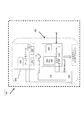
図1Aは、本明細書による、デスクトップSDL装置100のブロック図である。デスクトップSDL装置(3Dプリント装置)100は、プリントモジュール200と、SDLビルドモジュール300とを備えている。前記プリントモジュールは、複数の媒体層をプリントするように構成することができ、また、前記ビルドモジュールは、3Dオブジェクトを形成するために、複数の個別媒体層を組み付けるように構成することができる。前記媒体層は、単一の黒インク、又は複数の色でプリントされたカラー色、又は無色、すなわち白色でプリントすることができる。前記ビルドモジュールは、完全な3Dオブジェクトを形成するために、個別3Dオブジェクト媒体層をカットし、また、前記個別層を一体に接合するように構成することができる。プリントモジュール200及びビルドモジュール300は、装置100内に一体的に連結させることができ、媒体層は、完成された3Dオブジェクトを製造するために、ビルドモジュール300に搬送される前に、プリントモジュール200において、片側プリント、又は両側プリントすることができる。
FIG. 1A is a block diagram of a
本明細書では、前記ビルドモジュールは、3Dオブジェクトを形成するために前記積層オブジェクトが組み付けられる、3Dプリントのモジュールとして記載する。ビルドモジュール、コレータモジュール、ビルドチャンバ及びビルドモジュール、SDLビルドモジュールという用語は、この特徴を説明するために様々に使用する。 In the present specification, the build module is described as a 3D print module in which the stacked objects are assembled to form a 3D object. The terms build module, collator module, build chamber and build module, SDL build module are variously used to describe this feature.
媒体層は、2Dプリントのために、プリントモジュール200に搬送される。プリントされた前記媒体層は、SDL処理での、最終的な3Dオブジェクトの、丁合及び組み付けのために、前記プリントモジュールから前記ビルドチャンバに搬送される。
The media layer is conveyed to the
上述の構成における媒体層は、シートの形態で供給される。前記媒体層は、好適には紙であるが、任意のシート材又はロール材を使用できることは理解されるであろう。媒体は、2Dプリントし、プロファイリングし、接合するためにデスクトップ装置100に提供され、それによって、完成したカラー3Dオブジェクトを製造する。
The medium layer in the above configuration is supplied in the form of a sheet. It will be appreciated that the media layer is preferably paper, but any sheet or roll material can be used. The media is provided to the
前記プリントモジュールは、丁合の前に、前記媒体層にインクを塗布するように構成された、従来の2Dプリンタを備えていてもよい。前記2Dプリンタは、標準的なインクジェットプリンタとすることができる。前記ビルドモジュールは、複数の媒体層における個々の媒体層を接合するように構成された接合モジュールを備えることができる。前記プリントモジュールは、前記媒体層の第1表面及び第2表面にプリントするように構成され得る。第1表面及び第2表面にプリントすることは、前記オブジェクトの表面の角度に関係なく、画像にじみを動作可能に減少させ、また色の精度を維持する。前記プリントモジュールは、複数の個別媒体層における1つ以上の個別媒体層の、1つ以上の表面に多数の色を塗布するように構成することができる。前記コレータは、3Dオブジェクトに関して所望の3D形状をもたらすために、複数の媒体層における個別媒体層のプロファイリングを行うように構成されたプロファイリングモジュールを備えることができる。前記プロファイリングモジュール及び前記接合モジュールは、単一のプロファイリング及び層接合モジュールに統合することができる。 The print module may comprise a conventional 2D printer configured to apply ink to the media layer prior to collation. The 2D printer can be a standard inkjet printer. The build module may comprise a joining module configured to join individual media layers in a plurality of media layers. The print module may be configured to print on a first surface and a second surface of the media layer. Printing on the first and second surfaces operably reduces image blur and maintains color accuracy regardless of the angle of the surface of the object. The print module can be configured to apply multiple colors to one or more surfaces of one or more individual media layers in a plurality of individual media layers. The collator can comprise a profiling module configured to profile individual media layers in a plurality of media layers to provide a desired 3D shape for a 3D object. The profiling module and the bonding module can be integrated into a single profiling and layer bonding module.
媒体層701にプリントされた画像600Aは、予め生成されたデジタルプリントファイルに従ってプリントされ、当該デジタルプリントファイルは、プリントすべき3Dオブジェクトのための、画像、プロファイル及び色情報を含んでいる。
The
デジタルプリントファイルを予め生成する例示的な構成でのステップを、本明細書において簡単に説明するが、当然のことながら、他の方法を提供できる。本技術分野で知られているように、3Dプリントは、プリントすべき3Dオブジェクトを表す3Dデータファイルから開始される。例えば、3D製品設計用の汎用業界基準ファイルフォーマットである、STL並びにOBJ及びVRML(カラー3Dプリント用)は、本発明と共に使用することができるが、当然のことながら、適当な代替物もまた使用できる。その後、色が生成され、前記データファイルで表されたモデルに適用される。こうしたファイル内のデータを読み取り、また、そのコンピュータモデルを、前記媒体層と等しい厚さの、プリント可能な層にスライスする。こうしたデータファイルの生成は通常、プリンタ100に接続されたPC又はコンピュータデバイスで行われるが、これは、こうした処理もまたプリント装置100で行えることから、限定して解釈されるべきではない。別の構成では、クラウド内で、又はモバイルデバイス、タブレット、携帯電話で、上記スライシングを実行できることが理解されるであろう。更に、本発明は、ファイル生成の上記方法に限定するのではなく、また、3Dプリントファイルを生成するために、任意の適当な方法を使用することができる。
Although steps in an exemplary configuration for pre-generating a digital print file are briefly described herein, it will be appreciated that other methods can be provided. As is known in the art, 3D printing begins with a 3D data file representing the 3D object to be printed. For example, STL and OBJ and VRML (for color 3D printing), which are general industry standard file formats for 3D product design, can be used with the present invention, but of course, suitable alternatives are also used it can. A color is then generated and applied to the model represented in the data file. The data in such a file is read and the computer model is sliced into a printable layer having a thickness equal to the media layer. Generation of such a data file is usually performed by a PC or a computer device connected to the
予め生成されたデジタルプリントファイルは、プリントジョブ及びSDLジョブを開始する前に、プリント装置100に供給され、又はさもなければ、プリント装置100にロードされる。明示しないが、プリント装置100は、プロセッサ又はコントローラ、並びに前記プリントファイルがロードされるメモリを含んでいる。
The pre-generated digital print file is supplied to the
前記デジタルプリントファイルは、コントローラ/プロセッサによって再び参照される、又は読み取られる。前記デジタルプリントファイルは、各媒体層701のための、一連の頂部側面−底部側面の画像対600A/600Bを有することができる。全ての媒体層の、第1側面及び第2側面の両面のための色画像情報もまた、前記デジタルプリントファイルに含まれている。 The digital print file is again referenced or read by the controller / processor. The digital print file may have a series of top side-bottom side image pairs 600A / 600B for each media layer 701. Color image information for both the first side and the second side of all media layers is also included in the digital print file.
図1A及び図1Bを参照して、本発明の構成による一体型デスクトップ2D及び3Dプリント装置100を説明する。
An integrated desktop 2D and
デスクトッププリント装置100は、プリントモジュール200と、コレータ又はビルドモジュール300と、を備えている。装置100は、SDLによるオブジェクトの製造を行う。図示の構成では、前記媒体はロール形態で供給される。前記例示的な構成における前記媒体は、紙は、ロール形態で供給され、また前記組上げオブジェクトの層を形成するために使用される。装置100は、プリントモジュール200における前記媒体のプリントと、前記プリントモジュールからコレーティング/ビルドモジュール300までの、また前記ビルド位置までの、前記プリントされた媒体の搬送を行う。
The
装置100は、連続インライン処理で、2Dプリント及び3Dプリント、又はプリントされた媒体層701の、丁合、接合及びプロファイリングによって、SDLによる3D組上げオブジェクトの製造を行うよう構成され得る。2−Dプリントは、前記媒体の片側又は両側、即ち片面又は両面であってもよい。
The
装置100は、プリントモジュール200及びコレーティング又はSDLモジュール300を経由するよう、前記媒体用に、ハウジング内に連続的な搬送パス又は通路を提供し、また画定する。装置100は、更に、送り又は搬送手段160を備える送り又は搬送モジュール150を備えている。装置100は、更に、感知手段170を含むものとすることができる。更に、装置100は、更に、前記送り又は搬送機構の制御を行うための制御手段180を含むものとすることができる。前記搬送モジュールは、必要に応じて、1つ以上のローラ又はガイドを含んでいる送り機構を含んでいる。また、搬送を制御するためのコントローラも備えられている。
The
検知手段170は、媒体にプリントされた画像又はその一部を検知するために、又は前記画像がプリントされるのと同時に前記媒体にプリントされた基準点マークを検知するために、1つ以上のセンサ、例えば、前記媒体の位置を検知するように構成された光学センサを備えているものとすることができる。感知手段170は、スキューを検知し、位置及び位置付けを検知し、また、前記媒体又は前記システム内での特定のプリントされた画像の前記位置付けを識別するために使用することができる。前記センサによって検知されたデータは、スキューの補正若しくは位置の補正を行うために、又は例えば、第1側面の前記画像を識別し、また前記第1側面における画像に対する前記第2側面画像を位置付けするよう、前記制御手段に供給又は出力し、また、そこで処理することができる。 Sensing means 170 may detect one or more images printed on the medium or a part thereof, or to detect a reference point mark printed on the medium at the same time as the image is printed. A sensor, for example, an optical sensor configured to detect the position of the medium may be provided. Sensing means 170 can detect skew, detect position and positioning, and can be used to identify the positioning of a particular printed image within the media or the system. The data detected by the sensor is used to perform skew correction or position correction, or for example, identify the image on the first side and position the second side image relative to the image on the first side. The control means can be supplied or output and processed there.
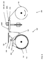
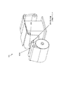
本発明の例示的な構成の装置100を、図1につき説明する。装置100は、媒体500を、ロール形態501で受け入れるためのロールサポート110を備えている。サポート110は、ハウジング112を有している。前記ハウジングは、第1内側面において、ロール容器又はサポート110を画定し、また第2外側面において、前記ハウジングは、媒体500が前記装置を通過して搬送されるときに、媒体500をガイドするためのガイド113を画定している。装置100は、前記媒体が2Dプリント及び3Dプリント用に前記装置を通過するための搬送パス140を画定している。
An
プリントモジュール200は、第1プリントステーション210と、第2プリントステーション220と、プリントヘッド230とを備えている。例示的な構成では、プリントヘッド230は両方のプリントステーションでプリントするように構成されている。しかしながら、別な構成では、2つのプリントヘッドを設けることができることは、理解されるであろう。プリントヘッド230はインクジェットプリントヘッドとすることができる。第1表面505A及び第2表面505Bを有してロール形態501で供給される媒体500は、ロール501から引き出され、また第1側面505Aをプリントするための第1プリントステーション210に搬送される。前記媒体は、その後、第2側面505Bをプリントするための第2プリントステーション220に搬送される。例示的な構成の装置100では、第1側面505Aは、前記組上げオブジェクト層の下側面を画定し、また、第2側面505Bは、前記組上げオブジェクト層701の上側面を規定する。
The
前記例示的な構成の搬送手段160は、送りローラ161〜165及びガイド113、163を備えている。搬送手段160は、更に、テイクアップローラ164を備えている。テイクアップローラ164は、前記システム内に移動可能に取り付けられている。テイクアップローラ164は、第1上方位置164Aと第2下方位置164Bとの間で上下移動するように取り付けられている。テイクアップローラ164は、前記媒体がプリント及び前記装置を通過して搬送されるときに、前記媒体の張力を維持するように、また前記ビルドプレートに搬送するように設けられている。テイクアップローラ164は、組上げ及びプリントの同時動作を容易にする。さらに、ピックアップローラ165を、不用材料510の回収のために設けることができる。
The conveying means 160 having the above exemplary configuration includes
搬送手段160は、更に、スプロケット送り又は搬送用に構成された、紙と共に使用するための、スプロケット送り手段165又はニップローラ166を備えるものとすることができる。適当な代替手段がスプロケット送り又はニップローラに設けられることもまた、理解されるであろう。ローラ及びガイドの異なる構成を設けてよいこと、また、前記例示的な構成の前記媒体に搬送するために、搬送手段160又は送り機構165と併せて、付加的又は代替的なガイド又はローラを設けてよいことは、理解されるであろう。必要に応じて、前記搬送パスの選択された位置に、付加的な駆動ローラ、ピンチローラ、ニップローラ又はガイドを設けてもよいことは、理解されるであろう。
The transport means 160 may further comprise sprocket feed means 165 or nip
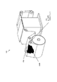
丁合又はビルドモジュール300は、積層オブジェクト製造法による3Dオブジェクトの組上げのために設けられている。ビルドモジュール300は、ビルドプレート310、接着剤分注手段320、カット手段321及びヒートプレート330を備えている。前記オブジェクトは、モジュール300のビルドチャンバ内で組み上げられる。
The collation or build
接着剤分注手段320及びカット手段321は、多機能ヘッド322に取り付けられたものとすることができる。前記接着剤分注手段及び前記カット手段は、前記ビルドプレートの上方領域に、取り付けられ、また動作する。前記接着剤分注手段及び前記カット手段は、例えば、必要に応じて、ビルドプレート310の上方を移動するための、X−Yフレームに取り付けられたものとし得る。前記接着剤分注手段が前記ビルドプレート上方で動作できるような適当な他の構成もまた使用できることは理解されるであろう。
The adhesive dispensing means 320 and the cutting means 321 can be attached to the
ビルドプレート310は、前記システム内で第1上昇位置と第2下降位置との間を移動することができる。前記ビルドプレートは、前記オブジェクトを組み上げるために、媒体の順次の層をビルドプレート300に追加するときに、下降する。カット手段321及び接着剤分注手段320は、前記オブジェクト形状のカッティングと、前記オブジェクトの媒体層701を形成する媒体500への接着剤の塗布を提供するように構成されている。 カット手段321は、前記媒体に、一連のクロスハッチカットを形成し、また、前記媒体の輪郭部分を切り抜くように構成されている。第1媒体層701Aは、接着剤が塗布される、ビルドプレート310又は他のベース層に供給することができる。後続の層701A、701B等は、その上に順次組み上げられる。
The
搬送手段160は、前記装置を通した前記媒体の搬送のために、前記第1側面及び前記第2側面のプリントのために、必要に応じて、前記ロールから前記ビルドモジュールに至る既にプリントされた媒体層の搬送のために、またカット及び接着剤の塗布のために設けられている。搬送手段160は、前記媒体を前方、後方に移動させるように、又は、別の動作のために必要に応じて、移動を停止させるように制御する。送りローラ161は、例えば、プリントを制御するために、前記搬送パス内での前記媒体の位置決めが可能になるように、必要に応じて、時計回り及び反時計回りに回転するように構成されている。連続動作を行うために、第1プリントステーション210で第1画像600Bがプリントされた媒体500の部分は、前記システムを通して搬送され、テイクアップローラ及び駆動ローラは、背中合わせ対(600A、600B)の第2画像600Aのプリントのために、第2プリントステーション220における媒体500の適正部分を位置付けするための制御を提供する。
The transport means 160 has already been printed from the roll to the build module as needed for printing the first side and the second side for transporting the medium through the apparatus. It is provided for transporting the media layer and for applying cuts and adhesives. The
この搬送手段はまた、前記媒体の前記第2側面にプリントすべき前記画像又は前記マーク/複数の前記画像又は前記マークが、前記第1側面にプリントされた、これらのものに対して正しく位置付けされるように、必要に応じて、位置及び/又はスキューの補正をもたらす。 The conveying means is also correctly positioned with respect to the image or the mark / the plurality of images or the mark to be printed on the second side of the medium, those printed on the first side. As such, correction of position and / or skew is provided as needed.
前記例示的な構成のロール501の媒体500は、スプロケット送り機構165によって送るように構成された、連続ロール形態の紙を備えている。スプロケット送り紙の様々な形態を設けることができ、例えば対応する形式のスプロケット送り機構によって搬送するように構成された、1つ又は2つのマージンを有する紙により設けることができることは、理解されるであろう。紙又は類似物のスプロケット送りロールが使用される場合、前記送り機構は、装置100の最初から最後までの搬送パス140全体を通しての、前記媒体の配置及びアラインメントの制御を行うために使用することができることは、理解されるであろう。上述したように、例えば、「ニップ」ローラ166等の、代替物を設けることができる。
The
搬送パス140を更に詳細に説明する。例示的な構成では、紙は、ガイド113に対して外側のパスを経て、前記第2プリントステーションに搬送される。ガイド113は、前記第2プリントステーションへの搬送がロール501からの媒体500の送りを妨げないことを保証するように配置されている。加えて、ガイド113は、前記媒体を前記第2プリントステーションに向かわせるように働く。ガイド113は、順番に、前記ロールを反転させて、プリントのための他方の側面を差し出す。
The transport path 140 will be described in more detail. In an exemplary configuration, the paper is conveyed to the second print station via an outer path with respect to the
図2から図7につき、本発明による連続インラインプリントで2D及び3Dプリントをするための処理を説明する。 The processing for 2D and 3D printing by continuous inline printing according to the present invention will be described with reference to FIGS.
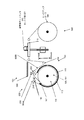
図2−ステップ1:下側面インクプリント
図2及び関連する斜視面である図11及び図13につき、本発明の例示的な構成による、下側面画像600Bをプリントするステップを説明する。
FIG. 2-Step 1: Lower Side Ink Printing With reference to FIG. 2 and the associated perspective views of FIGS. 11 and 13, the steps of printing a
紙は、媒体500の下側面505Aがプリントヘッド230に差し出されるように、送りローラ161から送り出される。下側面画像600Bをプリントする。前記下側面画像は、媒体500の下側面及び上側面に背中合わせとなるようプリントすべき画像対の第1画像である。
The paper is fed from the
更なる例示的な構成では、基準マーク605を、第1画像600Bと共にプリントすることができる。基準マーク605は、前記画像がどこに位置付けされているのかを示すために設けられる。基準マーク605は、前記媒体にプリントされた前記画像又は画像識別子に関する、位置情報又は他の識別情報を含んでいてもよい。基準マーク605は、前記上側面又は第2画像600Aを、対応する下側面画像600Bに対して正しい位置に位置付けすることを補助するために、又は更に、スキュー若しくは位置エラーを検知するために、感知手段170によって感知することができる。
In a further exemplary configuration, the fiducial mark 605 can be printed with the
システム100は、更に、スキュー調整手段180を備えるものとすることができる。検知手段170が基準マーク605を検知するときに、当該マークにおけるスキューを検知する場合、前記システムは、上側面画像600Aをプリントする前に、前記スキューを補正するように応答する。
The
検知手段170は、前記搬送パス全体を通した、異なる位置に設けることができる。例えば、検知手段170は、第2プリント位置及び前記ビルドプレートに配置することができる。検知手段170は、例えば、前記ビルドプレートの付近に設けることができる、又は多機能ヘッド322に組み込むことができる。
The detection means 170 can be provided at different positions through the entire transport path. For example, the
媒体500は、第1プリントステーション210から第2プリントステーション220に搬送されるときに反転する。この例示的な構成では、1つのプリントヘッドのみを使用しながら、前記反転により、前記媒体が連続インラインプリント処理で両側面にプリントされることを可能にする。
The medium 500 is reversed as it is transported from the
プリントヘッド230は、前記媒体の第1表面505Aの少なくとも一部を、当該媒体が第1プリントステーション210を通過するときに、プリントするように構成されている。同じプリントヘッド230は、第2表面505Bの少なくとも一部を、当該媒体が第2プリントステーション220を通過するときに、プリントするように構成されていてもよい。図1〜図3の例示的な構成では、第1プリントステーション及び第2プリントステーションが共通の搬送軸線に対して間隔を置いて配置されている。プリントヘッド230は、必要に応じて、第1プリントステーションと第2プリントステーションとの間を移動するように制御される。
The
別の構成では、媒体500の第1側505A及び第2側505Bを同時にプリントできるように、即ち、前記第1プリントステーション及び前記第2プリントステーションの両方で前記媒体の前面及び後面に対応する第1側面及び第2側面を同時にプリントできるように、第2プリントヘッド230´を設けることができる。
In another configuration, the
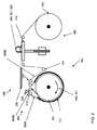
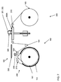
図3−ステップ2:上側面インクプリント
図3及び関連する斜視面である図12及び図14につき、本発明の例示的な構成による、上側面画像600Aをプリントするステップについて説明する。
FIG. 3-Step 2: Upper Side Ink Printing With reference to FIG. 3 and related perspective views of FIGS. 12 and 14, the steps of printing an
前記紙は、前記紙の上側面505Bが第2プリントステーション220でプリントヘッド230に差し出されるように、送りローラ110及び送りローラハウジング113の外側面の周りに連続する。
The paper continues around the outer surface of the
更なる構成によれば、上述のように、基準マーク605も下側面505Aに設けられる場合、センサ170は、前記下側面プリントから基準マーク605の位置を検知することができ、また、背中合わせの画像対600A/600Bの上側面画像600Aをどこに配置するかについて前記プリンタに命令を与える。
According to a further configuration, as described above, when the reference mark 605 is also provided on the
媒体500がシステム100を通してビルドモジュール300の方向に送られるときに、テイクアップローラ164は、プリント、カッティング及び接着の異なる動作が同時に実行できるように下方に移動する。2Dプリント又はインクプリントステップと、カッティング及び接着剤分注ステップは、独立している。
As the
図の例示的な構成は、単一のプリントヘッド230でありながら、ロール形式501で供給された媒体500の双方の側面にプリントすることができる、単一プリントヘッド230の有利な使用を示す。
The illustrated configuration illustrates an advantageous use of a
上述のような送りローラ161は、例えば、前記媒体をプリントヘッド230の下に移動させるために、時計方向及び逆の反時計方向に動くように構成されている。送りローラ161は、融通性を高め、また、前記システムを通した紙の送り及び搬送の制御を行うために、前方(反時計方向)及び後方(時計方向)に回転するように構成されている。送りローラ161が回転するときに、テイクアップローラ164は、それに応答して上下に移動する。単一のプリントヘッド230を有する図示の前記例示的な構成では、前記媒体がプリントのために、第1ステーション210を通過するとき、前記媒体は、プリントヘッドが利用できない第2プリントステーション220をも通過している。1つのプリントヘッド230を使用しているときの、送りローラ161及びテイクアップローラ164の使用は、必要に応じて、第2プリントステーション220における前記媒体の位置を付与する。第2プリントステーション220でのプリントの後、媒体500は、継続してビルドプレート310の上方領域に送られる。
The
図4及び図5-組上げ及びプレスのための紙搬送
媒体500の例示的な図4の搬送につき説明すると、この例示的な図の構成では、(先に塗布された両面画像を有する)紙が、前記ビルドプラットフォームに搬送される。このステップでは、前記媒体は、組上げオブジェクト700の層701A(701B等)を形成するためにカットされる。
FIGS. 4 and 5—Paper Transport for Assembly and Pressing Referring to the exemplary transport of
更に、上述のような場合、基準マーク605は、前記上側面画像をどこに配置するかを前記プリンタに命令するために、前記媒体の下側面に前記第1画像と共にプリントされ、これは、前記ビルドプレートの層配置が非常に正確となるように、ロール501をどの程度前進させるかを装置100に命令するために、利用することができる。
Further, in the case described above, a fiducial mark 605 is printed with the first image on the lower side of the media to instruct the printer where to place the upper side image, which is the build image. It can be used to instruct the
新しい層701A(それ以前にプリントされたページ)がビルドプレート310上に配置された後、ヒートプレート330がビルドプレート310上の位置に移動し、また、当該ビルドプレートがヒートプレート330にプレスされ、頂部層701Aと前記ビルドプレートに組み上げられているパーツ700(又は、場合によっては、第1媒体層用の、ベース層又はベースプレート)との間を確実に接触させる。ヒートプレート330は、その後、接着剤ディスペンサ320及びカット手段321が後退し、そして、次の層701Bで作業を開始できるように、遠ざかる。
After a new layer 701A (previously printed page) is placed on the
図6−プロファイルカット
プリントモジュール200は、前記組上げオブジェクトの第2層又は第3層(701B又は701C)を準備するために、(ステップ1及びステップ2のように、)媒体500のロール501の下側面505A及び上側面505Bにプリントする。例示的な構成では、カット手段321は、媒体500から組上げオブジェクト700の第1媒体層701Aをカットするように構成されており、第1媒体層701Aは、図4の例示的な構成では、ビルドプレート310上の頂部層701Aである。
FIG. 6-Profile Cut The
前記プロファイルが完成すると、カット手段321は、紙500の前記ロールからビルド層701Aを切り抜く。前記例示的な構成では、前記プロファイルカットがなされた後、接着剤が塗布される。その後、不用材料510はピックアップローラ165に対してインデックス付けされる。
When the profile is completed, the
テイクアップローラ164は、組上げオブジェクト700の層701のカットが、前記インクプリント処理に影響されることなく、行えるように構成されている。不用材料510が巻き上げられるときに、テイクアップローラ164は、いかなる弛みをも吸収するために上昇するように、また、媒体500での必要な張力を維持するように、構成されている。
The take-up
本発明の構成は、高度に効率的であり、また、廃棄物を削減する。前記媒体から切り抜かれた各媒体層のサイズは、前記組上げの要件に応じて変化する。例えば、前記媒体からプロファイリングされた各媒体層のサイズを適応的に変化させる代わりに、媒体層を供給するために、全体シート、例えばA4シートを前記組上げに配置することは、必要ではない。 The arrangement of the present invention is highly efficient and reduces waste. The size of each media layer cut out from the media varies according to the assembly requirements. For example, instead of adaptively changing the size of each media layer profiled from the media, it is not necessary to place an entire sheet, such as an A4 sheet, in the assembly to supply the media layer.
図7:接着剤塗布
上述のように、図7につき説明すると、前記プロファイルがカットされた後、接着剤が紙の頂部表面に塗布される。前記接着剤は、好適な構成では、インデックス付けが行われる前に塗布される。重ねて言うと、この全てが前記プリント処理を実行している間に同時に行われる。
FIG. 7: Adhesive application As described above, referring to FIG. 7, after the profile is cut, an adhesive is applied to the top surface of the paper. The adhesive is applied in a preferred configuration before indexing takes place. Again, all of this is done simultaneously while performing the print process.
図4〜7のシーケンスは、本発明の例示的な構成における、オブジェクトの媒体層の、搬送、カッティング及び接着剤塗布のためのステップを示す一方、別のシーケンスを使用できることは、理解されるであろう。 While the sequences of FIGS. 4-7 illustrate steps for conveying, cutting and applying adhesive to the media layer of an object in an exemplary configuration of the invention, it is understood that other sequences can be used. I will.
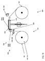
図8につき、本発明による別の構成を説明する。図8の構成では、ピックアップローラ165が設けられていない。ピックアップローラを使用する代わりに、不用材料510は、前記機械から出るときに、単に回収される。
Another configuration according to the present invention will be described with reference to FIG. In the configuration of FIG. 8, the
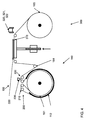
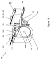
図9につき、本発明による、別の構成を説明する。図9の構成は、媒体層の同時両面プリントを提供する例示的な構成である。この構成では、2つのプリントヘッド230及び230´が設けられている。媒体500は、送りローラ161から取り出すことができ、そして、同時に両面にプリントする水平対向配置形態で動作する2つのプリントヘッド230及び230´の間を垂直方向に通過するように搬送させることができる。
9, another configuration according to the present invention will be described. The configuration of FIG. 9 is an exemplary configuration that provides simultaneous duplex printing of media layers. In this configuration, two
図示のような図9の構成では、前記プリントヘッドは、垂直送り用に構成されており、かつ前記プリントヘッドは、水平対向形態で動作するように構成されていると同時に、例えば、前記送りを垂直方向で、かつプリントを水平対向形態で行い得ることは理解されるであろう。 In the configuration of FIG. 9 as shown, the printhead is configured for vertical feed, and the printhead is configured to operate in a horizontally opposed configuration, eg, the feed It will be appreciated that printing can be done in the vertical direction and in a horizontally opposed configuration.
図10につき、本発明による、別の構成を説明する。この例示的な構成では、接着剤分注装置320は、前記媒体又は前記シートが前記ビルドプレートに搬送されるとき、前記ロール媒体の下側に配置されている。この構成は、有利にも、前記接着剤分注装置に起因する余分な重量を多機能ヘッド322から除外し、また、前記媒体又は前記シートが搬送されるのと同様に、前記接着剤分注装置が前記接着剤を塗布する全体的な処理を高速化する。
Another configuration according to the present invention will be described with reference to FIG. In this exemplary configuration, the
図15及び図16につき、本発明による、プリント装置100の別の構成を示す。図1〜図14の装置と同様の装置100は、一列に配列したプリントモジュール及びビルドモジュールを含んでいる。搬送手段160は、プリントすべき、また前記組上げオブジェクトの前記層を形成するために使用される前記媒体を、前記入力部からプリント部を経由し、そして前記ビルドモジュールまで運搬するように設けられている。搬送は、連続インライン搬送である。本発明の構成は、有利にも、3Dプリントのための、媒体層における第1側面及び第2側面における画像間のアラインメントを改善する。
15 and 16 show another configuration of the
本発明の構成は、改善されたデスクトップ3Dプリント装置を提供する。前記装置は、有利にも、片側又は両側形式での2Dプリント及び媒体の3−Dプリントを連続インライン処理で行うように構成されている。当然のことながら、この技術分野では、3Dプリントは前記SDL処理を指している。本明細書に記載されたように、プリントすべき前記媒体、本明細書の例示的な構成では、紙が、シート又はロールの形式で前記装置に供給され、紙は、両面プリントのために搬送され、また前記SDL処理のために、直接的に前記ビルドプレートに搬送される。 The arrangement of the present invention provides an improved desktop 3D printing device. The apparatus is advantageously configured to perform 2D printing in one-sided or double-sided form and 3-D printing of media in a continuous inline process. Naturally, in this technical field, 3D printing refers to the SDL processing. As described herein, in the exemplary configuration herein, the media to be printed, paper is fed to the device in the form of sheets or rolls, and the paper is transported for duplex printing. And transported directly to the build plate for the SDL process.
本発明の構成は、有利にも、例えば写真又は等高線地図の3Dプリントのために使用することができる。3Dプリントによって製造されたオブジェクトは、当該オブジェクトの前記層全体を通して仕様に精密に合致する色を有している。本発明の構成は、各層の第1表面及び第2表面の、色の制御を改善する。提供された前記手法は、精度が高く、また3Dオブジェクトの品質を改善する。 The arrangement of the invention can advantageously be used for 3D printing of eg photographs or contour maps. An object produced by 3D printing has a color that closely matches the specification throughout the layer of the object. The arrangement of the present invention improves the color control of the first and second surfaces of each layer. The provided approach is highly accurate and improves the quality of 3D objects.
3Dプリントのための両面アラインメントは、改善された3Dオブジェクトをもたらす。両面アラインメントは、テキストにとって問題ではないが、画像及びカラー品質に関して大きな影響を及ぼす。従って、本特許明細書記載の発明の前記システムは3Dプリントに改善された色をもたらす。 Double-sided alignment for 3D printing results in improved 3D objects. Double-sided alignment is not a problem for text, but has a significant impact on image and color quality. Thus, the system of the invention described in this patent specification provides improved color for 3D printing.
プリントジョブ用のシートが予めプリントされるまで待つ必要があるので、オフセットプリント処理について、1回限りのプリントジョブを行っているときに、遅れを含むという、更なる問題が生じる。 Since it is necessary to wait until the sheet for the print job is printed in advance, there is a further problem that the offset print process includes a delay when performing a one-time print job.
本発明の装置は、ある1つの態様では、1つの単一ハウジングにプリントモジュール及びビルドモジュールを備え、コンパクトで効率的な、改善された3Dプリント装置を提供する。 The apparatus of the present invention, in one aspect, includes a print module and a build module in one single housing to provide a compact, efficient and improved 3D printing apparatus.
別の態様では、3Dプリント用のプリントモジュールが提供される。前記プリントモジュールは、個別媒体層を組み付けて3Dオブジェクトを得るようビルドモジュールに配送するために、媒体層の高度に正確な2Dカラープリントを提供する。 In another aspect, a print module for 3D printing is provided. The print module provides a highly accurate 2D color print of the media layer for delivery to the build module to assemble the individual media layers to obtain 3D objects.
本実施形態による、両面プリントモジュール200は、3Dプリント処理の環境に有益に適用させることができる。媒体層が両側からプリントされるとき、画像の拡散が少なくなり、これにより、画像特徴の寸法制御がより良くなる。色の相互作用がプリントされた層の間で生じることなく、このことは、所望画像の忠実性を維持する。しかしながら、本実施形態による両面プリントモジュールは、前記媒体層の第1側面及び第2側面にプリントされた画像を整列させることが重要である他の両面プリント用途に、有益に適用させることができる。
The double-
本発明の構成は、効率的な処理を提供する。
The configuration of the present invention provides efficient processing.
Claims (44)
単一ハウジング内に一列に配列されたプリントモジュール及びビルドモジュールを備えており、
前記プリントモジュールは、前記オブジェクトのプリントされた媒体層を画定するよう、媒体の一部にプリントする1つ以上のプリントヘッドを備え、
前記ビルドモジュールは、ビルドプレート、カット手段、接合手段及び接着剤分注手段を備えており、また複数の個別媒体層から前記3Dオブジェクトを組み上げるように動作可能であり、
前記装置は、更に、
媒体入力部と媒体出力部との間で前記ハウジング内に画定された媒体搬送通路と、及び
前記入力部から前記媒体搬送通路に沿って前記プリントモジュールに、また引き続いて前記ビルドモジュールに、前記媒体を連続的に搬送するための搬送手段と、
を備えている、装置。 A desktop printing device for 3D printing an object, the desktop printing device comprising:
It has a print module and a build module arranged in a row in a single housing,
The print module comprises one or more printheads that print on a portion of media to define a printed media layer of the object;
The build module includes a build plate, a cutting means, a joining means, and an adhesive dispensing means, and is operable to assemble the 3D object from a plurality of individual media layers,
The apparatus further comprises:
A medium transport path defined in the housing between a medium input section and a medium output section; and the medium from the input section along the medium transport path to the print module and subsequently to the build module. Conveying means for continuously conveying,
Equipped with the device.
前記搬送手段は、連続インライン搬送動作で、前記媒体を、入力部から前記プリントモジュールに搬送するように、また前記ビルドモジュールに搬送するように構成されている、装置。 3. The apparatus according to claim 1, wherein the print module and the build module are arranged in a single line in a single integrated apparatus, and
The apparatus is configured to convey the medium from an input unit to the print module and to the build module in a continuous inline conveyance operation.
前記媒体の第1側面にプリントされた、画像、又は当該画像の一部、又は基準マークを感知するための感知手段を備えており、また
前記感知手段は、第1画像に背中合わせとなるよう前記媒体の第2側面における第2画像のプリントを制御するために、前記媒体の位置を制御する出力をコントローラに供給する、装置。 12. The apparatus according to any one of claims 1 to 11, further comprising:
Sensing means for sensing an image, a part of the image, or a fiducial mark printed on the first side of the medium, and the sensing means is back-to-back with the first image. An apparatus for providing an output to a controller for controlling the position of the media to control the printing of a second image on the second side of the media.
プリント手段及び搬送手段を備えており、前記搬送手段は、
媒体を、入力部から、第1側面及び第2側面に前記媒体のプリントを行うための前記プリント手段に搬送し、また、
前記両面プリントされた媒体を、前記プリントモジュールから前記3Dプリント装置のビルドモジュールまで搬送する
よう構成されている、3Dプリント装置用の両面プリントモジュール。 A double-sided printing module for a 3D printing apparatus, wherein the double-sided printing module comprises:
A printing unit and a conveyance unit, and the conveyance unit includes:
A medium is conveyed from the input unit to the printing means for printing the medium on the first and second side surfaces; and
A duplex printing module for a 3D printing apparatus configured to transport the duplex printed medium from the printing module to a build module of the 3D printing apparatus.
画像を前記媒体の第1側面にプリントし、また、マシン可読位置ロケータを前記媒体の前記第1側面にプリントするように構成されたプリントヘッドと、
前記マシン可読位置ロケータを読み取って、また、前記媒体の第2側面に対する前記媒体又は前記プリントヘッドの位置に変化をもたらすように構成され、前記第1側面に設けられた前記プリントされた画像に対する、前記第2側面に設けるべき画像の適正アラインメントを確保する、光学式読取機と、
を備えている、両面プリントモジュール。 The double-sided print module according to any one of claims 31 to 33, wherein the double-sided print module includes:
A printhead configured to print an image on a first side of the medium and print a machine-readable position locator on the first side of the medium;
Reading the machine readable position locator and also causing a change in the position of the medium or the print head relative to the second side of the medium, and for the printed image provided on the first side; An optical reader to ensure proper alignment of the image to be provided on the second side;
A double-sided print module.
44. The duplex printing module according to claim 43, wherein the media is configured to pass vertically between two print heads 230 and 230 'operating in a horizontally opposed print for simultaneous printing on both sides. There is a duplex printing module.
Applications Claiming Priority (3)
| Application Number | Priority Date | Filing Date | Title |
|---|---|---|---|
| GB1419670.3A GB2535133B (en) | 2014-11-04 | 2014-11-04 | Integrated Desktop 3-Dimensional Printing Apparatus |
| GB1419670.3 | 2014-11-04 | ||
| PCT/EP2015/075755 WO2016071420A1 (en) | 2014-11-04 | 2015-11-04 | Desktop printing apparatus for 3d printing an object and duplex printing module |
Publications (2)
| Publication Number | Publication Date |
|---|---|
| JP2017536266A true JP2017536266A (en) | 2017-12-07 |
| JP2017536266A5 JP2017536266A5 (en) | 2018-12-13 |
Family
ID=52118712
Family Applications (1)
| Application Number | Title | Priority Date | Filing Date |
|---|---|---|---|
| JP2017524458A Pending JP2017536266A (en) | 2014-11-04 | 2015-11-04 | Desktop printing apparatus and duplex printing module for 3D printing of objects |
Country Status (6)
| Country | Link |
|---|---|
| US (1) | US10751939B2 (en) |
| EP (1) | EP3215350A1 (en) |
| JP (1) | JP2017536266A (en) |
| CN (1) | CN107107466A (en) |
| GB (1) | GB2535133B (en) |
| WO (1) | WO2016071420A1 (en) |
Families Citing this family (11)
| Publication number | Priority date | Publication date | Assignee | Title |
|---|---|---|---|---|
| CN106426911A (en) * | 2016-11-14 | 2017-02-22 | 北京化工大学 | High-strength polymer 3D printing device and method |
| CN108789537B (en) * | 2018-04-07 | 2020-02-14 | 中山市得森纸品有限公司 | Longitudinal paper cutter with adjustable left blade for printer |
| WO2021054976A1 (en) * | 2019-09-20 | 2021-03-25 | Hewlett-Packard Development Company, L.P. | Media modification marks based on image content |
| CN113044634B (en) * | 2021-06-02 | 2021-08-10 | 中科长光精拓智能装备(苏州)有限公司 | Tension maintaining system |
| US11951679B2 (en) | 2021-06-16 | 2024-04-09 | General Electric Company | Additive manufacturing system |
| US11731367B2 (en) | 2021-06-23 | 2023-08-22 | General Electric Company | Drive system for additive manufacturing |
| US11958250B2 (en) | 2021-06-24 | 2024-04-16 | General Electric Company | Reclamation system for additive manufacturing |
| US11958249B2 (en) | 2021-06-24 | 2024-04-16 | General Electric Company | Reclamation system for additive manufacturing |
| US11826950B2 (en) | 2021-07-09 | 2023-11-28 | General Electric Company | Resin management system for additive manufacturing |
| US11813799B2 (en) | 2021-09-01 | 2023-11-14 | General Electric Company | Control systems and methods for additive manufacturing |
| CN114801523A (en) * | 2022-01-20 | 2022-07-29 | 陈双琴 | 3D printer control method and printer thereof |
Family Cites Families (13)
| Publication number | Priority date | Publication date | Assignee | Title |
|---|---|---|---|---|
| US4769652A (en) * | 1986-05-09 | 1988-09-06 | Advanced Color Technology, Inc. | Method and apparatus for handling sheet materials |
| JPS63246209A (en) * | 1987-04-01 | 1988-10-13 | Toyoda Gosei Co Ltd | Flexible mandrel |
| US5015312A (en) * | 1987-09-29 | 1991-05-14 | Kinzie Norman F | Method and apparatus for constructing a three-dimensional surface of predetermined shape and color |
| JP2000246804A (en) * | 1999-03-01 | 2000-09-12 | Minolta Co Ltd | Method and device for producing three-dimensionally molded article, and the three-dimensionally molde article |
| US6506477B1 (en) * | 1998-12-17 | 2003-01-14 | Minolta Co., Ltd. | Apparatus and method for forming three-dimensional object |
| US20020130909A1 (en) * | 2001-03-19 | 2002-09-19 | Eastman Kodak Company | Inkjet printing system with internal drum paper feed |
| US8282866B2 (en) * | 2008-06-30 | 2012-10-09 | Seiko Epson Corporation | Method and device for forming three-dimensional model, sheet material processing method, and sheet material processing device |
| GB2502294B (en) * | 2012-05-22 | 2015-12-09 | Mcor Technologies Ltd | Colour 3-Dimensional printing |
| GB2502295B (en) | 2012-05-22 | 2015-12-09 | Mcor Technologies Ltd | Colour 3-dimensional printing with 3D gamut mapping |
| GB2511316B (en) * | 2013-02-27 | 2015-06-24 | Mcor Technologies Ltd | Tack and bond adhesive system and method for layered object manufacture |
| JP6295561B2 (en) * | 2013-09-17 | 2018-03-20 | 株式会社リコー | Image inspection result determination apparatus, image inspection system, and image inspection result determination method |
| US20150094837A1 (en) * | 2013-10-01 | 2015-04-02 | Summet Sys Inc. | Moldless three-dimensional printing apparatus and method |
| JP2016210127A (en) * | 2015-05-12 | 2016-12-15 | 三菱電機株式会社 | Thermal printer |
-
2014
- 2014-11-04 GB GB1419670.3A patent/GB2535133B/en not_active Expired - Fee Related
-
2015
- 2015-11-04 JP JP2017524458A patent/JP2017536266A/en active Pending
- 2015-11-04 WO PCT/EP2015/075755 patent/WO2016071420A1/en active Application Filing
- 2015-11-04 EP EP15788097.2A patent/EP3215350A1/en not_active Withdrawn
- 2015-11-04 US US15/524,575 patent/US10751939B2/en active Active
- 2015-11-04 CN CN201580071799.6A patent/CN107107466A/en active Pending
Also Published As
| Publication number | Publication date |
|---|---|
| WO2016071420A1 (en) | 2016-05-12 |
| EP3215350A1 (en) | 2017-09-13 |
| GB2535133B (en) | 2019-07-24 |
| GB201419670D0 (en) | 2014-12-17 |
| GB2535133A (en) | 2016-08-17 |
| US10751939B2 (en) | 2020-08-25 |
| CN107107466A (en) | 2017-08-29 |
| US20180272603A1 (en) | 2018-09-27 |
Similar Documents
| Publication | Publication Date | Title |
|---|---|---|
| GB2535133B (en) | Integrated Desktop 3-Dimensional Printing Apparatus | |
| JP2018506443A (en) | Integrated desktop 3D printing device | |
| US9538020B2 (en) | Work flow and finishing for print production of photograph images | |
| US20080022866A1 (en) | Sheet punching and embossing machine with register orienting and method for operating a sheet punching and embossing machine | |
| CN102729689A (en) | Machine for producing books, in particular photo books and/or illustrated books | |
| JP2007296813A (en) | Bookbinding device | |
| JPH08503896A (en) | Method and apparatus for laminating hardened sections on folded paper | |
| JP2017536266A5 (en) | ||
| JP2014205249A (en) | Sheet processing device | |
| JP5740217B2 (en) | Cover manufacturing method and apparatus | |
| CN103676066B (en) | Camera lens and manufacture method thereof | |
| KR101747658B1 (en) | Method for Binding Printed Matter Using Laminating Film | |
| GB2569486A (en) | Paper roll machine | |
| JP6578575B2 (en) | Corrugated sheet manufacturing equipment | |
| US20150036220A1 (en) | Target recording medium and method for manufacturing target recording medium | |
| JP6582355B2 (en) | Corrugated sheet manufacturing equipment | |
| US8980405B2 (en) | Automated lenticular photographic system | |
| US10843498B2 (en) | Automated process for the manufacture of at least one printed work from at least one sheet | |
| US20200368965A1 (en) | System and method for sheeting and stacking 3d composite printed sheets | |
| US10751935B2 (en) | Substrate blank shearing and precise stack location apparatus and method for web fed presses | |
| US9892288B2 (en) | Process for manufacturing decorative multilayer coatings method of use thereof | |
| JP2015066525A (en) | Adhesive coating device, bookbinding device, adhesive coating method and bookbinding method | |
| JP2011093330A (en) | Bookbinding method | |
| JP2016007839A (en) | Sealed letter creation device | |
| JP2010137378A (en) | Bookbinding device and imaging system equipped with bookbinding device |
Legal Events
| Date | Code | Title | Description |
|---|---|---|---|
| A521 | Written amendment |
Free format text: JAPANESE INTERMEDIATE CODE: A523 Effective date: 20181102 |
|
| A621 | Written request for application examination |
Free format text: JAPANESE INTERMEDIATE CODE: A621 Effective date: 20181102 |
|
| A131 | Notification of reasons for refusal |
Free format text: JAPANESE INTERMEDIATE CODE: A131 Effective date: 20200107 |
|
| A601 | Written request for extension of time |
Free format text: JAPANESE INTERMEDIATE CODE: A601 Effective date: 20200331 |
|
| A601 | Written request for extension of time |
Free format text: JAPANESE INTERMEDIATE CODE: A601 Effective date: 20200526 |
|
| A02 | Decision of refusal |
Free format text: JAPANESE INTERMEDIATE CODE: A02 Effective date: 20200915 |