JP2017536174A - Muscle wall defect prosthesis and deployment system - Google Patents
Muscle wall defect prosthesis and deployment system Download PDFInfo
- Publication number
- JP2017536174A JP2017536174A JP2017525974A JP2017525974A JP2017536174A JP 2017536174 A JP2017536174 A JP 2017536174A JP 2017525974 A JP2017525974 A JP 2017525974A JP 2017525974 A JP2017525974 A JP 2017525974A JP 2017536174 A JP2017536174 A JP 2017536174A
- Authority
- JP
- Japan
- Prior art keywords
- support
- prosthesis
- layer
- handle
- medical device
- Prior art date
- Legal status (The legal status is an assumption and is not a legal conclusion. Google has not performed a legal analysis and makes no representation as to the accuracy of the status listed.)
- Granted
Links
- 230000007547 defect Effects 0.000 title claims abstract description 64
- 210000003205 muscle Anatomy 0.000 title claims description 63
- 210000001519 tissue Anatomy 0.000 claims description 30
- 230000002093 peripheral effect Effects 0.000 claims description 24
- 230000009975 flexible effect Effects 0.000 claims description 15
- 238000000034 method Methods 0.000 claims description 15
- 210000000056 organ Anatomy 0.000 claims description 12
- 230000015572 biosynthetic process Effects 0.000 claims description 5
- 230000004888 barrier function Effects 0.000 claims description 3
- 239000011248 coating agent Substances 0.000 claims description 2
- 238000000576 coating method Methods 0.000 claims description 2
- 206010060954 Abdominal Hernia Diseases 0.000 abstract description 3
- 210000004872 soft tissue Anatomy 0.000 abstract description 2
- 239000000463 material Substances 0.000 description 54
- 210000003815 abdominal wall Anatomy 0.000 description 40
- -1 polypropylene Polymers 0.000 description 28
- 206010019909 Hernia Diseases 0.000 description 15
- 239000004743 Polypropylene Substances 0.000 description 14
- 229920001155 polypropylene Polymers 0.000 description 14
- 230000008439 repair process Effects 0.000 description 13
- 101700004678 SLIT3 Proteins 0.000 description 11
- 102100027339 Slit homolog 3 protein Human genes 0.000 description 11
- 239000004698 Polyethylene Substances 0.000 description 6
- 229920000573 polyethylene Polymers 0.000 description 6
- 229920000139 polyethylene terephthalate Polymers 0.000 description 6
- 239000005020 polyethylene terephthalate Substances 0.000 description 6
- 241000283690 Bos taurus Species 0.000 description 5
- 108010035532 Collagen Proteins 0.000 description 5
- 102000008186 Collagen Human genes 0.000 description 5
- 238000005452 bending Methods 0.000 description 5
- 229920001436 collagen Polymers 0.000 description 5
- 241000282414 Homo sapiens Species 0.000 description 4
- 229920001343 polytetrafluoroethylene Polymers 0.000 description 4
- 239000004810 polytetrafluoroethylene Substances 0.000 description 4
- 229920000295 expanded polytetrafluoroethylene Polymers 0.000 description 3
- 230000001605 fetal effect Effects 0.000 description 3
- 238000003780 insertion Methods 0.000 description 3
- 230000037431 insertion Effects 0.000 description 3
- 230000010354 integration Effects 0.000 description 3
- 239000011159 matrix material Substances 0.000 description 3
- 229920001296 polysiloxane Polymers 0.000 description 3
- 208000021970 Abdominal wall defect Diseases 0.000 description 2
- 241000283073 Equus caballus Species 0.000 description 2
- 241001465754 Metazoa Species 0.000 description 2
- 239000002202 Polyethylene glycol Substances 0.000 description 2
- 229920002385 Sodium hyaluronate Polymers 0.000 description 2
- 210000001015 abdomen Anatomy 0.000 description 2
- DPXJVFZANSGRMM-UHFFFAOYSA-N acetic acid;2,3,4,5,6-pentahydroxyhexanal;sodium Chemical compound [Na].CC(O)=O.OCC(O)C(O)C(O)C(O)C=O DPXJVFZANSGRMM-UHFFFAOYSA-N 0.000 description 2
- 239000000560 biocompatible material Substances 0.000 description 2
- 239000012620 biological material Substances 0.000 description 2
- 239000001768 carboxy methyl cellulose Substances 0.000 description 2
- 235000010948 carboxy methyl cellulose Nutrition 0.000 description 2
- 239000008112 carboxymethyl-cellulose Substances 0.000 description 2
- 210000003754 fetus Anatomy 0.000 description 2
- 210000002837 heart atrium Anatomy 0.000 description 2
- 210000000936 intestine Anatomy 0.000 description 2
- 230000003387 muscular Effects 0.000 description 2
- HLXZNVUGXRDIFK-UHFFFAOYSA-N nickel titanium Chemical compound [Ti].[Ti].[Ti].[Ti].[Ti].[Ti].[Ti].[Ti].[Ti].[Ti].[Ti].[Ni].[Ni].[Ni].[Ni].[Ni].[Ni].[Ni].[Ni].[Ni].[Ni].[Ni].[Ni].[Ni].[Ni] HLXZNVUGXRDIFK-UHFFFAOYSA-N 0.000 description 2
- 229910001000 nickel titanium Inorganic materials 0.000 description 2
- 229920003023 plastic Polymers 0.000 description 2
- 239000004033 plastic Substances 0.000 description 2
- 229920002463 poly(p-dioxanone) polymer Polymers 0.000 description 2
- 239000000622 polydioxanone Substances 0.000 description 2
- 229920000728 polyester Polymers 0.000 description 2
- 229920001223 polyethylene glycol Polymers 0.000 description 2
- 229920000642 polymer Polymers 0.000 description 2
- 229920001027 sodium carboxymethylcellulose Polymers 0.000 description 2
- 229940010747 sodium hyaluronate Drugs 0.000 description 2
- YWIVKILSMZOHHF-QJZPQSOGSA-N sodium;(2s,3s,4s,5r,6r)-6-[(2s,3r,4r,5s,6r)-3-acetamido-2-[(2s,3s,4r,5r,6r)-6-[(2r,3r,4r,5s,6r)-3-acetamido-2,5-dihydroxy-6-(hydroxymethyl)oxan-4-yl]oxy-2-carboxy-4,5-dihydroxyoxan-3-yl]oxy-5-hydroxy-6-(hydroxymethyl)oxan-4-yl]oxy-3,4,5-trihydroxyoxane-2- Chemical compound [Na+].CC(=O)N[C@H]1[C@H](O)O[C@H](CO)[C@@H](O)[C@@H]1O[C@H]1[C@H](O)[C@@H](O)[C@H](O[C@H]2[C@@H]([C@@H](O[C@H]3[C@@H]([C@@H](O)[C@H](O)[C@H](O3)C(O)=O)O)[C@H](O)[C@@H](CO)O2)NC(C)=O)[C@@H](C(O)=O)O1 YWIVKILSMZOHHF-QJZPQSOGSA-N 0.000 description 2
- 229920002994 synthetic fiber Polymers 0.000 description 2
- 108010023728 Alloderm Proteins 0.000 description 1
- ZAMOUSCENKQFHK-UHFFFAOYSA-N Chlorine atom Chemical compound [Cl] ZAMOUSCENKQFHK-UHFFFAOYSA-N 0.000 description 1
- 208000027536 Femoral Hernia Diseases 0.000 description 1
- 208000005422 Foreign-Body reaction Diseases 0.000 description 1
- 208000029836 Inguinal Hernia Diseases 0.000 description 1
- 229920000339 Marlex Polymers 0.000 description 1
- 239000004677 Nylon Substances 0.000 description 1
- 229920000954 Polyglycolide Polymers 0.000 description 1
- 208000035965 Postoperative Complications Diseases 0.000 description 1
- 239000004792 Prolene Substances 0.000 description 1
- 241000282887 Suidae Species 0.000 description 1
- 108010069331 Surgimend Proteins 0.000 description 1
- 208000031737 Tissue Adhesions Diseases 0.000 description 1
- 230000002745 absorbent Effects 0.000 description 1
- 239000002250 absorbent Substances 0.000 description 1
- 238000004873 anchoring Methods 0.000 description 1
- CYQFCXCEBYINGO-IAGOWNOFSA-N delta1-THC Chemical compound C1=C(C)CC[C@H]2C(C)(C)OC3=CC(CCCCC)=CC(O)=C3[C@@H]21 CYQFCXCEBYINGO-IAGOWNOFSA-N 0.000 description 1
- 210000004207 dermis Anatomy 0.000 description 1
- 235000014113 dietary fatty acids Nutrition 0.000 description 1
- 230000002708 enhancing effect Effects 0.000 description 1
- 239000000194 fatty acid Substances 0.000 description 1
- 229930195729 fatty acid Natural products 0.000 description 1
- 150000004665 fatty acids Chemical class 0.000 description 1
- 238000002513 implantation Methods 0.000 description 1
- 230000000968 intestinal effect Effects 0.000 description 1
- 238000002357 laparoscopic surgery Methods 0.000 description 1
- 239000003562 lightweight material Substances 0.000 description 1
- 239000007769 metal material Substances 0.000 description 1
- 229920001778 nylon Polymers 0.000 description 1
- 235000020660 omega-3 fatty acid Nutrition 0.000 description 1
- 229940012843 omega-3 fatty acid Drugs 0.000 description 1
- 230000000149 penetrating effect Effects 0.000 description 1
- 230000035790 physiological processes and functions Effects 0.000 description 1
- 239000004417 polycarbonate Substances 0.000 description 1
- 229920000515 polycarbonate Polymers 0.000 description 1
- 239000004633 polyglycolic acid Substances 0.000 description 1
- 239000002861 polymer material Substances 0.000 description 1
- 239000004627 regenerated cellulose Substances 0.000 description 1
- 230000002787 reinforcement Effects 0.000 description 1
- 230000003014 reinforcing effect Effects 0.000 description 1
- 231100000241 scar Toxicity 0.000 description 1
- 238000000926 separation method Methods 0.000 description 1
- 210000003491 skin Anatomy 0.000 description 1
- 210000001835 viscera Anatomy 0.000 description 1
- 239000011800 void material Substances 0.000 description 1
- 238000003466 welding Methods 0.000 description 1
Images


Classifications
-
- A—HUMAN NECESSITIES
- A61—MEDICAL OR VETERINARY SCIENCE; HYGIENE
- A61F—FILTERS IMPLANTABLE INTO BLOOD VESSELS; PROSTHESES; DEVICES PROVIDING PATENCY TO, OR PREVENTING COLLAPSING OF, TUBULAR STRUCTURES OF THE BODY, e.g. STENTS; ORTHOPAEDIC, NURSING OR CONTRACEPTIVE DEVICES; FOMENTATION; TREATMENT OR PROTECTION OF EYES OR EARS; BANDAGES, DRESSINGS OR ABSORBENT PADS; FIRST-AID KITS
- A61F2/00—Filters implantable into blood vessels; Prostheses, i.e. artificial substitutes or replacements for parts of the body; Appliances for connecting them with the body; Devices providing patency to, or preventing collapsing of, tubular structures of the body, e.g. stents
- A61F2/0063—Implantable repair or support meshes, e.g. hernia meshes
- A61F2002/0072—Delivery tools therefor
-
- A—HUMAN NECESSITIES
- A61—MEDICAL OR VETERINARY SCIENCE; HYGIENE
- A61F—FILTERS IMPLANTABLE INTO BLOOD VESSELS; PROSTHESES; DEVICES PROVIDING PATENCY TO, OR PREVENTING COLLAPSING OF, TUBULAR STRUCTURES OF THE BODY, e.g. STENTS; ORTHOPAEDIC, NURSING OR CONTRACEPTIVE DEVICES; FOMENTATION; TREATMENT OR PROTECTION OF EYES OR EARS; BANDAGES, DRESSINGS OR ABSORBENT PADS; FIRST-AID KITS
- A61F2/00—Filters implantable into blood vessels; Prostheses, i.e. artificial substitutes or replacements for parts of the body; Appliances for connecting them with the body; Devices providing patency to, or preventing collapsing of, tubular structures of the body, e.g. stents
- A61F2/0077—Special surfaces of prostheses, e.g. for improving ingrowth
- A61F2002/009—Special surfaces of prostheses, e.g. for improving ingrowth for hindering or preventing attachment of biological tissue
Abstract
腹壁ヘルニア等の軟組織欠損を修復するための送達デバイス及び埋込型プロテーゼ。送達デバイスは、プロテーゼの第1層と第2層との間で入れ子にされる支持体(4)を含む。支持体は、入れ子にされた送達デバイス及びプロテーゼの折畳みを容易にするための脆弱ゾーン(3)を含む。支持体からハンドルが延在する。支持体にスパイン(12)が設けられる。【選択図】図1A delivery device and an implantable prosthesis for repairing soft tissue defects such as abdominal wall hernias. The delivery device includes a support (4) nested between a first layer and a second layer of the prosthesis. The support includes a nested delivery device and a fragile zone (3) to facilitate folding of the prosthesis. A handle extends from the support. A spine (12) is provided on the support. [Selection] Figure 1
Description
[0001] 本発明は、ヘルニア及び筋肉壁欠損の修復を容易にする装置及び方法に関する。より詳細には、本発明は、筋肉壁欠損上へのプロテーゼの位置決め及び固定を補助するシステムに関する。 [0001] The present invention relates to an apparatus and method for facilitating repair of hernias and muscle wall defects. More particularly, the present invention relates to a system that assists in positioning and securing a prosthesis over a muscle wall defect.
[0002] 患者の腹壁筋の筋肉壁欠損又はヘルニアを修復する一方法は、欠損を通してかつ患者の筋肉壁の内側になるようにプロテーゼの材料又はメッシュを挿入することである。従って、プロテーゼは、一般に欠損より大きく、筋肉壁に対して平面の向きで位置決めされて、全体として欠損を覆う。次いで、プロテーゼは、通常、縫合糸及び/又はタッカー等の固定具を使用して、欠損を包囲する筋肉壁又は組織の内面に固定される。 [0002] One method of repairing a muscle wall defect or hernia in a patient's abdominal wall muscle is to insert a prosthetic material or mesh through the defect and inside the patient's muscle wall. Accordingly, the prosthesis is generally larger than the defect and is positioned in a planar orientation relative to the muscle wall to cover the defect as a whole. The prosthesis is then secured to the muscular wall or the inner surface of the tissue surrounding the defect, usually using a fastener such as a suture and / or tucker.
[0003] ヘルニアを修復する第2の方法は、筋肉壁欠損を通してプロテーゼの材料又はメッシュを配置し、それを筋肉壁と後鞘との間に平面の向きで位置決めすることである。 [0003] A second method of repairing a hernia is to place a prosthetic material or mesh through a muscle wall defect and position it in a planar orientation between the muscle wall and the back sheath.
[0004] 筋肉壁欠損の内面に対するプロテーゼの方向付け、位置決め及び固定を補助するプロテーゼデバイスが近年開発されている。これらのデバイスは、一般に、(a)折り曲げて欠損を通して配置することができるプロテーゼ又は基部、(b)プロテーゼと組み合わされ、欠損を通して配置された後のプロテーゼを平面の向きに仕向ける支持部材又はワッシャ、及び(c)欠損を通って延在することができ、プロテーゼを腹壁に縫合するか又はタッカーで固定する間、プロテーゼを筋肉壁の近くに又は筋肉壁に接して保持するために使用することができるハンドル又は位置決めストラップからなる。その後、プロテーゼが適所に固定されると、位置決めストラップの少なくとも一部は切断され、プロテーゼ及び筋肉壁の前方の組織を縫合して閉じることができる。 [0004] Prosthetic devices have recently been developed to assist in the orientation, positioning and fixation of the prosthesis with respect to the inner surface of the muscle wall defect. These devices generally include: (a) a prosthesis or base that can be folded and placed through the defect; (b) a support member or washer that is combined with the prosthesis and directs the prosthesis after placement through the defect in a planar orientation; And (c) can extend through the defect and can be used to hold the prosthesis near or against the muscle wall while the prosthesis is sutured to the abdominal wall or secured with a tucker. It consists of a handle or positioning strap. Thereafter, when the prosthesis is secured in place, at least a portion of the positioning strap can be cut and the tissue in front of the prosthesis and muscle wall can be sutured closed.
[0005] 米国特許第7101381号は、パッチ上に配置された弾性支持部材を含むプロテーゼについて記載しており、弾性支持部材はパッチを平面形態に仕向けるように構成及び配置されている。しかしながら、プロテーゼの層に取り付けられたこの追加の支持部材は、患者に永久的に埋め込まれ、かつ、追加的な硬さ又は剛性をもたらし、患者の腹壁の輪郭に沿うプロテーゼの機能を妨げる可能性がある。この配置により、動きかつ起伏のある患者の腹壁に対してパッチが平坦なままであることを確実にすることがより困難になる。パッチと患者の腹壁との間の平坦かつ密着した結合は、腹部内の組織又は腸がプロテーゼと腹壁との間に挟まり、(特に、上述したヘルニアを修復する第1方法の場合に)ヘルニアを再発させる可能性がないことを確実にするために必要である。 US Pat. No. 7,101,381 describes a prosthesis that includes an elastic support member disposed on a patch, the elastic support member being configured and arranged to direct the patch to a planar configuration. However, this additional support member attached to the prosthesis layer may be permanently implanted in the patient and provide additional stiffness or rigidity, impeding the function of the prosthesis along the contour of the patient's abdominal wall. There is. This arrangement makes it more difficult to ensure that the patch remains flat against the moving and undulating patient's abdominal wall. The flat and intimate bond between the patch and the patient's abdominal wall allows the tissue or intestine in the abdomen to be sandwiched between the prosthesis and the abdominal wall, particularly in the case of the first method of repairing a hernia described above. It is necessary to ensure that there is no possibility of recurrence.
[0006] 米国特許出願公開第2011/0144667号は、プロテーゼの基部に取り付けられるか又は縫合されるのではなく、代わりに浮遊している支持ワッシャについて記載することにより、この支持部材からもたらされる高度の硬さを解決することを試みている。しかしながら、このデバイスのこのワッシャは、依然としてプロテーゼの密閉された層内に収容され、プロテーゼと共に永続的に埋め込まれる。このプロテーゼは、米国特許第7101381号に記載された支持部材と比較した場合、幾分か硬さが軽減する可能性があるが、硬さの軽減によりプロテーゼを平面形態に仕向ける支持ワッシャの機能も損なわれる。外科医は、このプロテーゼが平面形態にあり、プロテーゼが筋肉壁欠損を完全に覆うことを確実にしなければならないため、このデバイスの使用が困難であると感じる人が多い。 [0006] US Patent Application Publication No. 2011/0144667 describes the elevation resulting from this support member by describing a support washer that is not attached or stitched to the base of the prosthesis but instead is floating. I am trying to solve the hardness. However, this washer of the device is still housed within the sealed layer of the prosthesis and is permanently embedded with the prosthesis. This prosthesis may be somewhat less stiff when compared to the support member described in U.S. Pat. No. 7,101,381, but it also has the function of a support washer that directs the prosthesis into a planar configuration by reducing the hardness. Damaged. Surgeons often find it difficult to use the device because the prosthesis is in a planar configuration and it must be ensured that the prosthesis completely covers the muscle wall defect.
[0007] 米国特許第7101381号に記載された追加の支持部材、及び米国特許出願公開第2011/0144667号に記載された浮遊する支持ワッシャの両方は、患者に埋め込まれる追加の異物材料を導入している。この追加の異物材料は、それ自体が腹壁にこわばりを加えるだけでなく、プロテーゼの周囲の筋肉修復をより硬くかつより弱くする結果となる異物反応を引き起こすことにより、腹壁の柔軟性及び生理的機能をさらに損なう。 [0007] Both the additional support member described in US Pat. No. 7,101,381 and the floating support washer described in US Patent Application Publication No. 2011/0144667 introduce additional foreign material to be implanted in the patient. ing. This additional foreign material not only adds stiffness to the abdominal wall itself, but also causes a foreign body reaction that results in a stiffer and weaker muscle repair around the prosthesis, thereby enhancing the flexibility and physiological function of the abdominal wall. Further damage.
[0008] 当業者であれば、パッチ、特にパッチの周縁部を腹壁に固定することの重要性を理解するであろう。これにより、パッチと筋肉壁との間の密着した結合が促進され、パッチの腹壁への経時的な統合が促進される。そのため、下にある組織又は器官がパッチと腹壁との間に挟まることになる可能性がなく、上記固定がなければ、こうした挟まりにより不完全な修復、ヘルニアの再発又は他の術後合併症に至る可能性がある。 [0008] Those skilled in the art will appreciate the importance of securing the patch, particularly the peripheral edge of the patch, to the abdominal wall. This promotes a tight bond between the patch and the muscle wall and promotes integration of the patch into the abdominal wall over time. Therefore, there is no possibility that the underlying tissue or organ will be pinched between the patch and the abdominal wall, and without such fixation, this pinching can lead to incomplete repair, hernia recurrence, or other postoperative complications. There is a possibility.
[0009] 次に米国特許第7101381号は、組織又は筋肉壁欠損上でパッチを位置決めするのを容易にするために、(層の間の)ポケットの下への入口を提供するように適合されたアクセス開口部を有するパッチについて記載している。このポケットには、パッチを腹壁に固定するために縫合糸又はタッカーがアクセスすることも可能である。しかしながら、パッチが腹壁内に比較的深く位置決めされると、外科医は固定中にパッチのアクセス開口部を見ることが困難であるか、又はさらには不可能である。従って、外科医にとって、(通常はパッチより小さい)筋肉壁欠損を通してパッチのアクセス開口部内に器具を配置し、患者の器官、組織、又は他の重要な構造を意図せず穿孔することなく、パッチの周縁部を腹壁の内面に固定することは非常に困難である。 [0009] US Pat. No. 7,101,381 is then adapted to provide an entrance under the pocket (between layers) to facilitate positioning the patch over a tissue or muscle wall defect. A patch having an open access opening is described. This pocket can also be accessed by sutures or tuckers to secure the patch to the abdominal wall. However, if the patch is positioned relatively deep within the abdominal wall, it is difficult or even impossible for the surgeon to see the patch's access opening during fixation. Thus, for the surgeon, the instrument is placed through the muscle wall defect (usually smaller than the patch) into the access opening of the patch, without unintentionally perforating the patient's organs, tissues, or other important structures. It is very difficult to fix the peripheral edge to the inner surface of the abdominal wall.
[0010] 米国特許第7101381号に記載されている、パッチを平面形態に仕向ける弾性支持部材は、パッチ上に配置される。この支持部材とパッチ上に弾性部材を配置する縫い目とが、アクセス開口部の外周、及び、アクセス開口部又はポケットを通るパッチの周辺部分又は周縁部へのアクセスを防止する障壁となる。従って、パッチのアクセス開口部内からパッチの周辺部分を腹壁に縫合するか又はタッカーで固定することは不可能である。これにより、腹壁へのパッチの完全な統合が阻止される可能性があり、患者の組織又は器官がパッチと腹壁との間に挟まる可能性がある。 [0010] An elastic support member, described in US Pat. No. 7,101,381, that directs the patch to a planar configuration is disposed on the patch. The support member and the seam on which the elastic member is disposed on the patch serve as a barrier for preventing access to the outer periphery of the access opening and the peripheral portion or peripheral portion of the patch passing through the access opening or pocket. Therefore, it is impossible to sew or fix the peripheral part of the patch to the abdominal wall from within the access opening of the patch or fix it with a tacker. This can prevent complete integration of the patch into the abdominal wall and can cause the patient's tissue or organ to be sandwiched between the patch and the abdominal wall.
[0011] Stephen Pankratzによる米国特許出願公開第2014/117270号として公開された出願(その内容は本明細書に組み込まれる)では、支持体の挿入、位置決め及び取外しを容易にするように構成されたプロテーゼ及び配置デバイスについて記載されている。配置デバイスは、プロテーゼに挿入可能である支持体を含み、支持体に取り付けられたハンドルを有する。ハンドルには、支持体に曲げモーメントを与えるのに十分な堅さが与えられる。支持体は、ほぼ平面の表面を有し、プロテーゼが支持される展開位置と、プロテーゼに挿入され、プロテーゼから取り除かれる折畳み位置との間の支持体の移動を容易にする脆弱ゾーンがある。プロテーゼに対する適切な支持により、外科医は、プロテーゼを固定するために縫合糸又はステープルを挿入することができ、縫合糸が誤った方向に向けられるリスクが軽減する。ハンドルの堅さとの組合せによる脆弱ゾーンにより、プロテーゼが適切に固定されると支持体を折り畳むことができる。 [0011] In an application published as US Patent Application Publication No. 2014/117270 by Stephen Pankratz, the contents of which are incorporated herein, it was configured to facilitate the insertion, positioning and removal of the support. A prosthesis and placement device are described. The placement device includes a support that is insertable into the prosthesis and has a handle attached to the support. The handle is given sufficient stiffness to impart a bending moment to the support. The support has a generally planar surface and there is a frangible zone that facilitates movement of the support between a deployed position where the prosthesis is supported and a folded position where the prosthesis is inserted and removed from the prosthesis. Proper support for the prosthesis allows the surgeon to insert sutures or staples to secure the prosthesis, reducing the risk of the suture being oriented in the wrong direction. The fragile zone in combination with the handle stiffness allows the support to fold when the prosthesis is properly secured.
[0012] 支持体を折り畳んで引き抜くために必要な力は、支持体が取り除かれる際に腹壁の切開部を包囲する組織に対する損傷を回避するために最小限であるべきである。米国特許出願公開第2014/117270号に示されているデバイスは、取り除くために必要な力を許容可能なレベルで維持するが、状況によってはさらなる低減が望ましい。 [0012] The force required to fold and pull the support should be minimal to avoid damage to the tissue surrounding the incision in the abdominal wall when the support is removed. While the device shown in US 2014/117270 maintains an acceptable level of force required to remove it, further reduction is desirable in some circumstances.
[0013] 本発明の目的は、こうした力のさらなる低減を達成しようとする、プロテーゼ用の支持デバイスを提供することである。 [0013] It is an object of the present invention to provide a support device for a prosthesis that seeks to achieve further reduction of such forces.
[0014] 本発明は、ヘルニア又は腹壁欠損上に重なるように使用されるプロテーゼを埋め込むための、患者の体内に埋め込まれる異物材料の量を制限しながら腹壁へのプロテーゼの方向付け、位置決め及び固定を補助するデバイス及び方法に関する。 [0014] The present invention directs, positions and secures the prosthesis to the abdominal wall while limiting the amount of foreign material implanted in the patient's body for implanting the prosthesis used to overlay the hernia or abdominal wall defect. It is related with the device and method which assist.
[0015] 本明細書に記載するヘルニア又は軟組織もしくは筋肉の修復デバイス及び方法は、生体適合性埋込型プロテーゼ又はパッチと、修復部位にプロテーゼを送達する送達デバイスとを組み合わせて含む、システムを利用する。生体適合性埋込型プロテーゼ又はパッチは、筋肉壁欠損を覆う材料の第1層からなる。第1層に材料の第2層又はリムが、各層の周縁部において取り付けられ、第1層と第2層との間に形成された内部空間又はポケットへのアクセスを可能にする穴又はスリットの形態の開口部を提供する。 [0015] The hernia or soft tissue or muscle repair device and method described herein utilizes a system that includes a combination of a biocompatible implantable prosthesis or patch and a delivery device that delivers the prosthesis to the repair site. To do. A biocompatible implantable prosthesis or patch consists of a first layer of material covering a muscle wall defect. A second layer or rim of material is attached to the first layer at the periphery of each layer, and a hole or slit is provided that allows access to the interior space or pocket formed between the first and second layers. Provide an opening in the form.
[0016] プロテーゼの両層は、患者の腹壁に沿うのに十分可撓性のある生体適合性材料からならなければならず、患者の筋肉壁欠損を覆わなければならない。合成材料を使用することができ、それは、筋肉壁欠損の永続的な覆い、及び将来的なヘルニア再発を防止するための補強を提供するように意図される。これらの材料としては、限定されないが、ポリプロピレン、ポリエチレン、ポリエチレンテレフタレート及び/又は発泡ポリテトラフルオロエチレンが挙げられ、それらを合わせて編むか又は織って、可撓性平面シートに配置することができる。こうした材料の例としては、ポリエチレンテレフタレートから構成される、Atrium Medical社のProLite及びProLite Ultraポリプロピレンヘルニアメッシュ、Ethicon社のProleneポリプロピレンヘルニアメッシュ、Bard社のMarlexポリプロピレンヘルニアメッシュ、及びEthicon社のMersileneメッシュが挙げられる。これらの合成材料は、ポリグリコール酸等の生体吸収性材料と共編みすることも可能である。合成又は合成生体吸収性編材料は、内臓に面する側を、腸又は他の組織の癒着を低減又は防止する材料又は材料の組合せでコーティングすることも可能である。これらの材料の例としては、限定されないが、架橋オメガ3脂肪酸油と、ヒアルロン酸ナトリウム、カルボキシメチルセルロース及びポリエチレングリコールの組合せと、酸化再生セルロースと、コラーゲン酸化膜と、モノクリル及びポリジオキサノン膜の組合せとが挙げられる。筋肉壁欠損上へのプロテーゼの位置決め及び固定を補助する、ポリプロピレン及び生体吸収性コーティングの組合せから構成されるプロテーゼを利用する、現時点で入手可能なデバイスとしては、Atrium Medical社のVPatchTM(架橋オメガ3脂肪酸油コーティングポリプロピレンを利用)、及びC. R. Bard社のVentrelex ST(ヒアルロン酸ナトリウム、カルボキシメチルセルロース及びポリエチレングリコールの組合せ、並びにポリプロピレンを利用)が挙げられる。 [0016] Both layers of the prosthesis must be made of a biocompatible material that is flexible enough to follow the patient's abdominal wall and cover the patient's muscle wall defect. Synthetic materials can be used, which are intended to provide a permanent covering for muscle wall defects and reinforcement to prevent future hernia recurrence. These materials include, but are not limited to, polypropylene, polyethylene, polyethylene terephthalate and / or expanded polytetrafluoroethylene, which can be knitted or woven together and placed on a flexible flat sheet. Examples of such materials include Atrium Medical's ProLite and ProLite Ultra polypropylene hernia mesh, Ethicon's Prolene polypropylene hernia mesh, Bard's Marlex polypropylene hernia mesh, and Ethicon's Mersilene mesh composed of polyethylene terephthalate. It is done. These synthetic materials can be co-knitted with a bioabsorbable material such as polyglycolic acid. The synthetic or synthetic bioabsorbable knitted material can also be coated on the side facing the viscera with a material or combination of materials that reduces or prevents intestinal or other tissue adhesions. Examples of these materials include, but are not limited to, a cross-linked omega-3 fatty acid oil, a combination of sodium hyaluronate, carboxymethyl cellulose and polyethylene glycol, oxidized regenerated cellulose, collagen oxide film, and a combination of monochlor and polydioxanone films. Can be mentioned. A currently available device that utilizes a prosthesis comprised of a combination of polypropylene and a bioabsorbable coating to assist in positioning and anchoring the prosthesis over a muscle wall defect is Atrium Medical's VPatch ™ (cross-linked omega). 3 fatty acid oil coated polypropylene), and CR Bard's Ventrelex ST (uses a combination of sodium hyaluronate, carboxymethylcellulose and polyethylene glycol, and polypropylene).
[0017] 代替的に、プロテーゼは、ヒト組織(同種移植片)又は動物組織(異種移植片)から供給されるコラーゲン基質からなる場合がある。これらの材料は、移植後にかつ経時的に患者自身の細胞及び組織によって再構築することができるコラーゲン組織を提供する。これらの供給源は、通常、合成供給源が推奨されない場合に使用され、感染又は汚染されたヘルニア欠損の修復中に使用されることが多い。現時点で入手可能なコラーゲン基質材料の例としては、ウシ胎児から供給される異種移植片であるTEI Biosicence社のSurgiMend、ヒトの死体から供給されるLifeCell社のAlloderm同種移植片、及びブタから供給されるLifeCell社のStrattice異種移植片が挙げられる。 [0017] Alternatively, the prosthesis may consist of a collagen matrix supplied from human tissue (allograft) or animal tissue (xenograft). These materials provide collagen tissue that can be reconstructed by the patient's own cells and tissues after implantation and over time. These sources are typically used when synthetic sources are not recommended and are often used during the repair of infected or contaminated hernia defects. Examples of collagen matrix materials currently available are TEI Biosicence SurgiMend, a xenograft supplied from a fetal bovine, LifeCell Alloderm allograft supplied from a human cadaver, and pigs. LifeCell's Stratice xenografts.
[0018] プロテーゼを送達するために、可撓性がありかつ平面の支持片からなる別々の送達デバイス及びハンドルも提供される。支持片は、その自由物体の平面形態から折り曲げられるか又は一時的に折り畳まれることになる、弾性かつ/又は可撓性の特性を備えた材料からなる。送達デバイスの支持片は、使用前はプロテーゼの2つの層の間のポケット内に配置されるか、又はその中で「入れ子」にされている。支持片は、ポケット内に位置決めされると解放することができ、プロテーゼの2つの層の間でその本来の平面の向きに戻るように広がることができる。送達デバイスの支持片は、平坦又は平面の向きに向かって偏りを与えるが、依然として、修復部位における配置中にその変形を可能にするのに十分柔軟である、固有の剛性を備える材料から構成される。有用な材料としては、限定されないが、ポリプロピレン、ポリエチレンテレフタレート、ポリエチレン、シリコーン、ニチノール及び/又はポリテトラフルオロエチレン等のポリマー材料が挙げられる。 [0018] Separate delivery devices and handles consisting of flexible and planar support pieces are also provided for delivering the prosthesis. The support piece is made of a material with elastic and / or flexible properties that will be folded or temporarily folded from the planar form of the free object. The delivery device support piece is placed in or “nested” within the pocket between the two layers of the prosthesis prior to use. The support piece can be released once positioned in the pocket and can spread back between its two layers of prosthesis to its original planar orientation. The delivery device support piece is composed of a material with inherent stiffness that is biased towards a flat or planar orientation, but still flexible enough to allow its deformation during placement at the repair site. The Useful materials include, but are not limited to, polymeric materials such as polypropylene, polyethylene terephthalate, polyethylene, silicone, nitinol and / or polytetrafluoroethylene.
[0019] 送達デバイスのハンドルは、テザー、ストラップ又は延長部の形態とすることができ、プロテーゼ内で入れ子にされている間に支持片の位置決めに補助するために使用することができる。ハンドルはプロテーゼに取り付けられず、むしろ支持片に取り付けられるか又は支持片と連続するため、プロテーゼが適所に固定された後、ハンドルを使用して取外し可能片をプロテーゼからかつ欠損から外に取り外すことも可能である。ハンドルは、外科医によって欠損の外側で保持さ又は処理されている間、筋肉壁欠損及び周囲組織を通して延在するのに十分に長い可撓性材料で構成される。また、ハンドルは、ハンドルを引き寄せて取外し可能片を欠損に対して位置決めするか、又は、取外し可能片をプロテーゼからかつ筋肉壁欠損から外に取り外す間、外科医によって掛けられる力に耐えるのに十分な耐久性もなければならない。ハンドルを構成することができる材料のいくつかの例としては、限定されないが、ポリプロピレン、ポリエチレンテレフタレート及び/又はポリテトラフルオロエチレンが挙げられる。 [0019] The handle of the delivery device can be in the form of a tether, strap or extension and can be used to assist in positioning the support piece while nested within the prosthesis. Because the handle is not attached to the prosthesis, but rather is attached to or is continuous with the support piece, the handle can be used to remove the removable piece from the prosthesis and out of the defect after the prosthesis is secured in place Is also possible. The handle is constructed of a flexible material that is long enough to extend through the muscle wall defect and surrounding tissue while being held or processed outside the defect by the surgeon. The handle is also sufficient to withstand the force applied by the surgeon while pulling the handle to position the removable piece relative to the defect or removing the removable piece from the prosthesis and out of the muscle wall defect. It must also be durable. Some examples of materials that can make up the handle include, but are not limited to, polypropylene, polyethylene terephthalate, and / or polytetrafluoroethylene.
[0020] 支持片がプロテーゼ内で入れ子にされている場合、2つの片を、筋肉壁欠損を通して配置する間、1つの片として折り曲げるか又は折り畳むことができる。欠損を通して配置されると、送達デバイスはその本来の平面形状に戻ることができる。これにより、典型的には可撓性のある又は薄い材料から構成されるプロテーゼが腹壁に対して平面の向きに仕向けられる。その後、支持片に固定されるか又は支持片と連続するハンドルを使用して、欠損に対してプロテーゼを位置決めすることができる。次いで、例として縫合糸及び/又はトラッカーを使用することにより、プロテーゼを、欠損を包囲する腹壁筋又は組織に固定することができる。送達デバイスの支持片は、好ましくは固定具が貫通し難い材料から構成され、腹壁へのプロテーゼの固定中、縫合針又はタックが下にある器官又は組織を意図せず貫通するのを防ぐために使用することができる。その後、支持片を強制的に折り曲げるか又は折り畳み、送達デバイスの取外し可能部分又は使用可能なハンドルを引き寄せることにより、筋肉壁欠損を通してプロテーゼ(又は基部)から回収し取り外すことができる。これにより、プロテーゼのみが埋め込まれたままで、筋肉壁欠損の好都合な修復が可能になる。支持部材又はワッシャが残されないため、プロテーゼは患者の腹壁の動く輪郭によりよく沿うことができる。患者に埋め込まれる異物材料も少なくなり、より良好でより柔軟な筋肉壁欠損の修復につながる。 [0020] If the support piece is nested within the prosthesis, the two pieces can be folded or folded as one piece during placement through the muscle wall defect. When placed through the defect, the delivery device can return to its original planar shape. This directs the prosthesis, typically composed of a flexible or thin material, in a planar orientation relative to the abdominal wall. The prosthesis can then be positioned relative to the defect using a handle that is secured to or continuous with the support piece. The prosthesis can then be secured to the abdominal wall muscle or tissue surrounding the defect, using sutures and / or trackers as examples. The delivery device support piece is preferably constructed of a material that is difficult to penetrate and is used to prevent the suture needle or tack from unintentionally penetrating the underlying organ or tissue during fixation of the prosthesis to the abdominal wall. can do. The support piece can then be withdrawn from the prosthesis (or base) through the muscle wall defect by forcibly folding or folding and pulling the removable portion of the delivery device or the usable handle. This allows for convenient repair of the muscle wall defect while only the prosthesis remains implanted. Because no support member or washer is left, the prosthesis can better follow the moving contours of the patient's abdominal wall. Less foreign material is implanted in the patient, leading to better and more flexible muscle wall defect repair.
[0021] 一実施形態では、プロテーゼの第1層と第2層又はリムとの間に生成される空間又はポケットにアクセスすることができ、それにより、第1片のリムの周囲に延在する第2層を筋肉壁に対して位置決め及び固定することができる。このポケットは、いずれの支持部材、ワッシャ、又は支持部材もしくはワッシャをパッチ上に配置する縫い目によっても妨げられない。従って、ポケットは、プロテーゼの周辺まで延在することができ、それにより、パッチのポケット内から、パッチの周縁部を腹壁に対して縫合するか又はタッカーで固定することが可能になる。 [0021] In one embodiment, a space or pocket created between the first layer and the second layer or rim of the prosthesis can be accessed, thereby extending around the rim of the first piece. The second layer can be positioned and secured relative to the muscle wall. This pocket is not obstructed by any support member, washer, or a seam that places the support member or washer on the patch. Thus, the pocket can extend to the periphery of the prosthesis, thereby allowing the peripheral edge of the patch to be sutured or tacked to the abdominal wall from within the patch pocket.
[0022] 本発明の1つの例示的な実施形態では、埋込型プロテーゼの第2層は、少なくとも1つの中心に位置する開口部を含むことができ、従って、第1層に対して材料の周縁リムを生成することができる。材料のリムを筋肉壁に対して位置決め及び固定することができるように、リムと第1層との間の空間又はポケットに穴を通してアクセスすることができる。 [0022] In one exemplary embodiment of the present invention, the second layer of the implantable prosthesis can include at least one centrally located opening, and thus, of the material relative to the first layer. A peripheral rim can be generated. The space or pocket between the rim and the first layer can be accessed through a hole so that the rim of material can be positioned and secured to the muscle wall.
[0023] 本発明の別の実施形態例によれば、埋込型プロテーゼの第1層は、少なくとも周縁部のいくつかの部分において折り重ねることができ、それにより、第2層又は材料のリムもしくは部分リムが生成される。材料のリムを筋肉壁に対して位置決め及び固定することができるように、リム又は部分リムと第1層との間の空間にアクセスすることができる。 [0023] According to another exemplary embodiment of the present invention, the first layer of the implantable prosthesis can be folded over at least some portions of the periphery, thereby providing a second layer or rim of material. Alternatively, a partial rim is generated. The space between the rim or partial rim and the first layer can be accessed so that the rim of material can be positioned and fixed relative to the muscle wall.
[0024] 本発明のさらに別の実施形態例によれば、プロテーゼの第2層は、第2層の少なくとも一部を横切って延在するスリットを含むことができ、それにより、材料の第2層を筋肉壁に対して位置決め及び固定することができるように、第1層と第2層との間の空間にアクセスすることが可能になる。 [0024] According to yet another example embodiment of the present invention, the second layer of the prosthesis can include a slit extending across at least a portion of the second layer, whereby a second of the material. It is possible to access the space between the first layer and the second layer so that the layer can be positioned and fixed relative to the muscle wall.
[0025] 一実施形態では、埋込型プロテーゼは、組織の腹壁への内部成長を可能にするように構成及び配置される複数の隙間を含む材料を使用して、少なくとも部分的に構成することができる。この材料としては、限定されないが、ポリエチレン又はポリエステルが挙げられ得る。この材料に対し、埋込型プロテーゼに対する組織又は器官の望ましくない癒着の形成を低減させる吸収性物質でコーティングすることも可能である。 [0025] In one embodiment, the implantable prosthesis is at least partially constructed using a material that includes a plurality of gaps configured and arranged to allow tissue ingrowth to the abdominal wall. Can do. This material can include, but is not limited to, polyethylene or polyester. The material can also be coated with an absorbent material that reduces the formation of undesirable tissue or organ adhesions to the implantable prosthesis.
[0026] さらに別の実施形態では、埋込型プロテーゼは、少なくとも部分的に、限定されないが、ブタ、ブタ胎児、ウシ、ウシ胎児又はウマ真皮を含む生体材料からなる。 [0026] In yet another embodiment, the implantable prosthesis is at least partially composed of biomaterials including but not limited to porcine, porcine fetus, bovine, fetal bovine or equine dermis.
[0027] 一実施形態では、筋肉壁及び筋肉壁欠損に面しかつそれに接して配置される埋込型プロテーゼの少なくとも一部は、組織との癒着の形成の影響を受けやすい。 [0027] In one embodiment, at least a portion of the implantable prosthesis facing and adjacent to the muscle wall and muscle wall defect is susceptible to formation of adhesions with the tissue.
[0028] 本発明のさらなる態様によれば、送達デバイスは、限定されないが、ポリプロピレン、ポリエチレン、シリコーン、ニチノール、又は他のタイプのプラスチック及び/もしくは金属材料からなる場合がある。 [0028] According to a further aspect of the invention, the delivery device may be comprised of, but not limited to, polypropylene, polyethylene, silicone, nitinol, or other types of plastic and / or metallic materials.
[0029] 別の実施形態では、送達デバイスは、外周縁部と、外周縁部から内向きに離間された内部空隙とを有する、ほぼ平面の支持片を有する。空隙に隣接して送達デバイスにハンドルが固定される。支持片は、脆弱ゾーン、好ましくはスリットもしくは折目又は可撓性の増大した領域を含み、それにより、送達デバイスを、その本来の形態からより容易に折り曲げるか又は折り畳み、埋込型プロテーゼ内にはめるか又はそれから取り除くことができる。 [0029] In another embodiment, the delivery device has a generally planar support piece having an outer peripheral edge and an internal cavity spaced inwardly from the outer peripheral edge. A handle is secured to the delivery device adjacent to the gap. The support piece includes a fragile zone, preferably a slit or crease or a region of increased flexibility, so that the delivery device can be folded or folded more easily from its native form into the implantable prosthesis. Can be fitted or removed from it.
[0030] 好ましくは、脆弱ゾーンは、外周部から空隙まで延在し、好ましくは、脆弱ゾーンは半径方向スリットである。 [0030] Preferably, the fragile zone extends from the outer periphery to the air gap, preferably the fragile zone is a radial slit.
[0031] テザー、ストラップ又は延長部の形態のハンドルは、埋込型プロテーゼ及び送達デバイスが欠損上に位置決めされるとき、取外し可能片及びプロテーゼを位置決めする際に使用するために、かつ適切に位置決め及び固定されたときにプロテーゼを取り除く際に使用するために、組織又は筋肉壁欠損を通して延在することができる。 [0031] A handle in the form of a tether, strap or extension is positioned for use in positioning the removable piece and prosthesis when the implantable prosthesis and delivery device are positioned over the defect and appropriately positioned. And can extend through tissue or muscle wall defects for use in removing the prosthesis when secured.
[0032] 好ましくは、ハンドルは、空隙に隣接して支持片に固定され、さらなる選好として、ハンドルは、支持片の脆弱ゾーンに対して直径方向に反対側である位置で送達デバイスに取り付けられる。ハンドルを、特にスリットの方向に対して鈍角である方向において引き寄せることにより、送達デバイスがメッシュ及び/又は筋肉壁に強制的に接触し、スリットの2つの面が互いに重なり、位置決めデバイスが折畳み形態に仕向けられる。これにより、位置決めデバイスは、その折畳み形態に仕向けられ、埋込型プロテーゼからかつ筋肉壁欠損から外に容易に取り外すことができる。空隙を設けることにより、支持片を折畳み状態で維持するために必要な力が低減することが分かった。好ましくは、ハンドルは、支持片の折曲げを促進するために、支持片に曲げモーメントを与えるのに十分な剛性を有する。 [0032] Preferably, the handle is secured to the support piece adjacent to the gap, and as a further preference, the handle is attached to the delivery device at a position that is diametrically opposite to the weakened zone of the support piece. By pulling the handle, particularly in a direction that is obtuse to the direction of the slit, the delivery device is forced into contact with the mesh and / or muscle wall, the two faces of the slit overlap each other, and the positioning device is in a folded configuration. Be directed. Thereby, the positioning device is directed to its folded configuration and can be easily removed out of the implantable prosthesis and out of the muscle wall defect. It has been found that providing the gap reduces the force required to maintain the support piece in the folded state. Preferably, the handle is sufficiently rigid to impart a bending moment to the support piece to facilitate folding of the support piece.
[0033] 好ましい実施形態では、ハンドルは、空隙から外周部に向かって外側にかつ脆弱ゾーンから離れる方向に延在する半径方向線に沿って支持片に接続される。ハンドル上に重なりかつ支持片の局所的な堅さを増大させるためにスパインが取り付けられる。 [0033] In a preferred embodiment, the handle is connected to the support strip along a radial line that extends outwardly from the air gap toward the outer periphery and away from the frangible zone. A spine is attached to overlap the handle and increase the local stiffness of the support piece.
[0034] ここで、本発明の実施形態について、添付図面を参照して単に例として説明する。これらの実施形態は、続く詳細な説明でさらに説明される。 [0034] Embodiments of the present invention will now be described by way of example only with reference to the accompanying drawings. These embodiments are further described in the detailed description that follows.
[0044] 本発明は、患者に埋め込まれる異物材料の量を制限しながら欠損を修復するための腹壁に対するプロテーゼの展開、位置決め及び固定を補助するデバイスである。筋肉壁欠損には、限定されないが、へそヘルニア、上腹壁ヘルニア、瘢痕ヘルニア又は他の腹壁ヘルニア、鼠径ヘルニア、大腿ヘルニア、及び腹腔鏡手術に使用されたトロカールから腹壁内に残された筋肉壁の欠損又は穴が含まれ得る。本明細書では、いくつかの例示的な実施形態のみを記載している。当業者であれば、本発明の構成要素のサイズ及び形状を含むパラメータ、並びに構成要素に使用される材料のタイプを、本明細書に記載する本発明の範囲内にありながら、異なるタイプ及び/又はサイズの腹壁欠損に対応するように変更し得ることを理解するであろう。 [0044] The present invention is a device that assists in the deployment, positioning and fixation of a prosthesis relative to the abdominal wall to repair a defect while limiting the amount of foreign material implanted in a patient. Muscle wall defects include, but are not limited to, navel hernia, upper abdominal wall hernia, scar hernia or other abdominal wall hernia, inguinal hernia, femoral hernia, and muscular wall left in the abdominal wall from trocars used for laparoscopic surgery Defects or holes can be included. Only a few exemplary embodiments are described herein. Those skilled in the art will recognize that the parameters, including the size and shape of the components of the present invention, and the types of materials used for the components, while remaining within the scope of the invention described herein, differing types and / Or it will be appreciated that it may be modified to accommodate a sized abdominal wall defect.
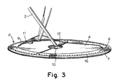
[0045] 最初に図3を参照すると、埋込型プロテーゼPは、少なくとも2つの並置される層7及び8からなる。層7及び8は、それぞれ生体適合性材料を用いて構成される。材料は可撓性があり、組織が腹壁内に内部成長し統合することを可能にするように配置される複数の隙間を含む。好適な材料としては、ポリプロピレン、ポリエステル、ポリテトラフルオロエチレン(PTFE)及び発泡ポリテトラフルオロエチレン(ePTFE)が挙げられる。さらなる選好として、層7、8に用いられる材料は編まれている。
[0045] Referring initially to FIG. 3, the implantable prosthesis P consists of at least two
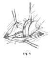
[0046] 第2層8は、第1層7に接して配置されたときに材料の周縁リムを生成する、中心に位置する穴9の形状の開口部を有する環として形成される。層7及び8は、縫合等によって周縁部で接続され、密閉されたアクセス可能な空間又はポケット11をもたらす。一実施形態例では、図4において7aとして示す、層7の患者の器官に面する側は、埋込型プロテーゼに対する組織又は器官の望ましくない癒着の形成を低減させる物質で覆われる。当業者であれば、これは、下にある層7が編材料又は複数の隙間を含む材料から構成される場合に特に重要であり、そうでなければ、経時的に下にある器官又は組織からの望ましくない癒着の形成が可能になり得ることを理解するであろう。
[0046] The
[0047] 代替実施形態では、層7及び8は、典型的にはヒト又は動物の組織に由来する、コラーゲン基質等の生体材料から構成される。好適な材料としては、ブタ、ブタ胎児、ウシ、ウシ胎児、ウマ及びヒトの死体組織が挙げられる。 [0047] In an alternative embodiment, layers 7 and 8 are comprised of a biomaterial, such as a collagen matrix, typically derived from human or animal tissue. Suitable materials include porcine, porcine fetus, bovine, fetal bovine, horse and human cadaver tissue.
[0048] ここで図1を参照すると、プロテーゼ送達デバイス1は、平面の支持片又はプラテン4とハンドル2とを含む。ハンドル2とプラテン4との分離を阻止するように、ハンドル2はプラテン4と一体的に形成される。プラテン4は、支持片がプロテーゼPの開口部9を通過することができるように折り畳まれた形態を採用するのに十分な可撓性を有する、弾性プラスチックポリマー材料等の生体適合性可撓性材料、典型的にはポリプロピレン、ポリエチレン、ポリエチレンテレフタレート、ポリ(グリコライド−コ−L−ラクタイド)、ポリジオキサノン及びシリコーンのうちの1つから構成される。
[0048] Referring now to FIG. 1, the prosthesis delivery device 1 includes a planar support piece or
[0049] プラテン4は、外周縁部5と中心空隙10を規定する半径方向内縁部6とを有する。典型的な応用では、外周縁部5及び内周縁部は両方とも円形であり、そのため、環を規定する。プラテン4を、縁部5、6を規定するようにシート状の材料からダイカットし、空隙10を設けるように材料を除去することができる。典型的には、プラテン4は、プロテーゼを完全に支持するように、プロテーゼの2つの層7、8の間に形成されたポケットの直径よりわずかに小さい直径を有する。プラテン4の直径は、3cm〜40cmで変更することができる。
The
[0050] 空隙10の直径は、層8の範囲にわたって実質的に連続した表面を維持するように選択され、典型的な応用では、0.2cm〜15cmの直径を有する。
[0050] The diameter of the void 10 is selected to maintain a substantially continuous surface over the range of the
[0051] 屈曲を容易にするために、プラテン4は脆弱ゾーンを有し、それは、図1の実施形態では、内縁部6から外周縁部5まで延在する半径方向のスリット3である。スリット3により、プラテンを図1に示すその本来の、すなわち平面形態から、図3に示す円錐形の折り畳まれた形態により容易に折り曲げることができる。平面形態では、スリット3の両縁部は、連続した平坦な表面及び周縁部を呈するように実質的に当接している。後述するように、スリット3の縁部の折り畳まれた状態への摺動を容易にするように、スリット3の半径方向外側部分は、3aに示すように逃げが付けられている。
[0051] To facilitate bending, the
[0052] 図1に示すように、ハンドル2は、可撓性があるが、プラテンの動きを制御しかつプラテン4の操作を可能にするために十分な剛性を有する。図1の実施形態では、ハンドル2は、プラテン4と一体的に形成され、プラテンから2cm〜20cm、ただしより好ましくはプラテンから5cm〜15cm延在している。ハンドル2は、プラテン4と同じ材料から、又は異なる機械的特徴が必要である場合は別の材料から作製することができる。好ましくは、ハンドル2に使用される材料は、ポリプロピレン、ポリエチレン、ナイロン又はポリカーボネートであり、幅は0.5mm〜20mmの範囲であるが、より好ましくは3〜6mmであり、厚さは0.5mm〜2.0mmであるが、より好ましくは0.7mm〜1.2mmであり、曲げ弾性率は125,000psi〜275,000psiである。
As shown in FIG. 1, the
[0053] ハンドル2は、プラテン4の内周縁部6に固定され、空隙10を通ってかつプラテン4の反対側の面に沿って延在する。ハンドル2は、プラテン4の、スリット3に対して直径方向に反対側に接続され、その終端部分2aは、スリット3から離れる方向においてプラテン4に沿って半径方向に延在する。プラテン4のハンドル2とは反対側に、ハンドル2と並置されるように補強スパイン12が配置され、スパイン12及びハンドル4は、超音波溶接又は他の好適な技法によってプラテン4に接続される。
The
[0054] 送達デバイス1上にプロテーゼPを組み付けるために、プラテン4の外周縁部5が下方に押されて、自由物体状態からの再構成に対応してスリット3により円錐体が形成される。プラテン4は、開口部9より小さい円周になるように折り畳まれると、プロテーゼPの2つの層7、8の間に形成されたポケット11内に位置決めすることができる。プラテン4は、位置決めされると解放され、図3に示されるように、その本来の平面の向きに戻され、層7及び8の間に入れ子にされ得る。送達デバイス1のプラテン4がプロテーゼPの層7、8の間に入れ子にされた状態で、送達デバイス1及びプロテーゼPを単一体として操作し、折り曲げるか又は屈曲させることができる。
[0054] In order to assemble the prosthesis P on the delivery device 1, the outer peripheral edge 5 of the
[0055] 筋肉壁欠損を完全に覆うために、外科医は、面積が筋肉壁欠損より大きいプロテーゼを選択する。下層修復として知られる修復において、プロテーゼは、筋肉壁を通して筋肉壁欠損の裏側又は後方に取り付けるために折り曲げるか又は丸めなければならない。送達デバイス1及びプロテーゼPは梱包され、別々に又は図3に示すように組み合わせて、使用者又は外科医に提示される。いずれの場合も、プラテン4のサイズは、層の間からかつ中央に位置する穴9から意図せずに又は非常に容易に滑り出ることなく、層7及び8の間にはまるのに十分大きいことが重要である。プラテン4が大き過ぎず、かつ層7及び8の間、及びポケット11内、並びに縫い目10によって生成された境界内にはまることができなければならないことも重要である。種々のサイズのプロテーゼPの異なる支持要件に対応するように、送達デバイスのプラテン4の厚さ、可撓性及び/又は弾性が選択される。
[0055] To completely cover the muscle wall defect, the surgeon selects a prosthesis that has a larger area than the muscle wall defect. In repairs known as underlayer repairs, the prosthesis must be folded or rolled to attach to the back or posterior of the muscle wall defect through the muscle wall. Delivery device 1 and prosthesis P are packaged and presented to the user or surgeon separately or in combination as shown in FIG. In any case, the size of the
[0056] 1つの特定の実施形態では、プラテン4は、125,000psi〜175,000psiの曲げ弾性率を有するポリプロピレン等のポリマーから形成される。アモルファスPETが好適な材料であることが分かった。使用されるポリマーの厚さは、概して0.05mm〜2.0mmであるが、好ましくは0.1mm〜1mmである。0.4mmの厚さが好適であることが分かった。取外し可能片の直径は、概して、ポケット11の内径より0.1mm〜5.0cm小さい。プラテン4の直径は、より具体的には、ポケット11の直径より0.5mm〜3.0mm小さい。
[0056] In one particular embodiment, the
[0057] プラテン4及びプロテーゼPが結合されると、外科医が、それらを例えば図4に示すように半分に丸めるか又は折り曲げ、筋肉壁欠損15を通して挿入することができる。腹壁の後側に配置されると、外科医は、結合されたプラテン4及びプロテーゼPを解放し、プラテン4がその弾性の特性によりその本来の平面形態に戻ることを可能にし得る。プラテン4の復元力により、同様にプロテーゼは平面形態に仕向けられ、プロテーゼPが適所に位置決めされる際にプロテーゼPの一時的な支持が提供される。これにより、典型的には軽量材料から構成されかつ薄い可能性のあるプロテーゼが、腹壁に対して広げられた平面の向きで維持される。これによって外科医が、例えば縫合糸又はタックを使用して、筋肉壁欠損を包囲する腹壁の後側にプロテーゼを固定することがより容易になる。
[0057] Once the
[0058] ハンドル2は、外科医がアクセスすることができるように筋肉壁欠損を通して延在するように構成される。外科医は、ハンドル2を使用して、図5、図6及び図7に示すように、プロテーゼと共に送達デバイス1のプラテン4を、筋肉壁に近接して位置決めして引っ張る。結合された送達デバイス1及びプロテーゼPが筋肉壁欠損に対して適所に置かれると、プロテーゼは筋肉壁欠損の内面又は後側に固定される。これは、縫合糸を使用することにより、又は図6及び図7に示すタッカー19を使用することにより行うことができる。タッカー19の端部を、例えば、プロテーゼの第1層7と第2層8との間のポケット11内に配置し、材料の第2層8を腹壁の後側に対して上方に押し上げることができる。タッカー19の端部から展開されるタックは、その後、材料の第2層8を腹壁の後側に固定することができる。図7は、このように腹壁に対して材料の第2層8を貫通するように展開されたタック29を示す。プロテーゼPが腹壁にかつ筋肉壁欠損の周囲に適切に固定されるまで、プロテーゼPの周縁部全体に沿って、後続するタックをこのように展開することができる。この手順の間、ハンドル2を使用して、タッカー19のアクセスの調整を可能にするように柔軟性がありながら、材料の層8と腹壁との間の密接な接触が確保される。送達デバイス1のプラテン4はタッカー19の下に位置するため、本来は下にある組織及び腸30等の器官を意図せず穿孔する可能性のある縫合糸又はタックをそらす。プロテーゼ2が完全に固定されると、組織又は器官は腹壁とプロテーゼとの間に留まることはできないはずである。
[0058] The
[0059] プラテン4によって提供される支持により、プロテーゼ内に別個の支持リングは不要となり、そのため、タッカー19は周縁部5でプロテーゼにアクセスすることができる。当業者であれば、1)腹部へのプロテーゼの良好な付加及び統合を確保するために、かつ2)メッシュが外れること及びヘルニアの再発又は筋肉壁欠損の不完全な修復を回避するように、プロテーゼと腹壁との間に組織及び器官が留まるのを防止するために、プロテーゼの周縁部にアクセスし、かつ、その周縁部を腹壁の後側に固定することが重要であることを理解するであろう。
[0059] The support provided by the
[0060] プロテーゼが筋肉壁に固定された後、プラテン4をプロテーゼのポケット11から取り除き、かつ、ハンドル2を引き寄せて、図8に示すようにプラテン4を強制的にその折畳み位置にすることにより、筋肉壁欠損を通して回収することができる。その後、組織及び皮膚の前層は閉じられ、互いに縫合される。
[0060] After the prosthesis is secured to the muscle wall, the
[0061] 空隙10が設けられることにより、プラテンが平面でありかつスリット3の縁部が整列するプラテンの自由物体状態から、図8に示すような折り畳まれた位置まで移動するためのプラテン4の抵抗が低減する。スパイン12もまた、プラテン4の剛性を局所的に増大させて、ハンドル2から力が加えられる際にプラテン4の屈曲を促進する。ハンドル2の堅さにより、プラテン4に曲げモーメントを加えることができ、それにより、スリット3の縁部が互いの面で摺動し、ほぼ円錐形の位置を採用する。終端部分3aによって与えられる逃げが、この初期移動を補助する。
[0061] By providing the
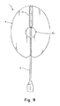
[0062] プロテーゼは、円形以外の形態を有することができ、例えば、図9に示すように楕円形であり得ることが明らかとなるであろう。空隙10も異なる形状とすることができるが、円形が好ましい。図9の楕円形実施形態のプラテン4におけるスリット3は、楕円形の長軸に配置され、ハンドル2の取付は、スリット3に対して直径方向に反対側である。
[0062] It will be apparent that the prosthesis may have a shape other than circular, for example, may be elliptical as shown in FIG. The
Claims (30)
外周縁部を備える第1層を有する生体適合性埋込型プロテーゼであって、拡張形状と縮小形状との間で変形されるのに十分な可撓性を有し、前記プロテーゼを送達デバイスと解除可能に係合させるインタフェースを有する生体適合性埋込型プロテーゼと、
前記筋肉壁欠損に対して前記プロテーゼを送達すること又は位置決めすることのうちの少なくとも一方のためのデバイスであって、前記デバイスの前記インタフェースに対する解除可能な係合のために折畳み形態を採用するのに十分な可撓性を備え、かつ、前記デバイスが前記インタフェースと解除可能に係合されるときに、前記プロテーゼを前記拡張形状で支持するための安定した自己支持型の拡大形態を採用するのに十分な可撓性を備えた支持体を有し、前記支持体が、第1面及び反対側の第2面、並びに前記第1面と前記第2面との間で前記支持体を貫通する開口部を有し、前記デバイスがハンドルをさらに含み、前記ハンドルが、前記開口部を通って延在し、かつ、前記支持体の前記第1面から離れる方向に延在可能である自由な第1部分と、前記支持体の前記第2面に取り付けられた前記ハンドルの第2部分と、を有し、前記支持体が、前記支持体による前記折畳み形態の採用を容易にする脆弱ゾーンと、前記支持体の、前記第2部分と反対側の前記第1面に取り付けられたスパインと、を含む、デバイスと、を備える医療デバイス。 A medical device for repairing a muscle wall defect,
A biocompatible implantable prosthesis having a first layer with an outer peripheral edge that is flexible enough to be deformed between an expanded shape and a reduced shape, wherein the prosthesis is connected to a delivery device. A biocompatible implantable prosthesis having an interface for releasable engagement;
A device for at least one of delivering or positioning the prosthesis relative to the muscle wall defect, employing a folded configuration for releasable engagement of the device with the interface Adopting a stable self-supporting enlarged configuration for supporting the prosthesis in the expanded configuration when the device is releasably engaged with the interface. A support body having sufficient flexibility, and the support body penetrates the support body between the first surface and the second surface on the opposite side, and between the first surface and the second surface. A free opening, wherein the device further includes a handle, the handle extends through the opening and is extendable away from the first surface of the support. First A fragile zone having a portion and a second portion of the handle attached to the second surface of the support, wherein the support facilitates adoption of the folded configuration by the support, and And a spine attached to the first surface of the support opposite to the second portion.
前記デバイスの前記プロテーゼに対する解除可能な係合のために折畳み形態を採用するのに十分な可撓性を備え、かつ、前記デバイスが前記プロテーゼと解除可能に係合されるときに、前記プロテーゼを拡張形状で支持するための安定した自己支持型の拡大形態を採用するのに十分な可撓性を備えた支持体であって、外周部、第1面及び反対側の第2面、並びに前記第1面と前記第2面との間で前記支持体を貫通する開口部を有し、前記デバイスがハンドルをさらに含み、前記ハンドルが、前記開口部を通ってかつ前記支持体の前記第1面から離れる方向に延在する自由な第1部分と、前記支持体の前記第2面に取り付けられた前記ハンドルの第2部分とを有し、前記支持体が、前記支持体による前記折畳み形態の採用を容易にする脆弱ゾーンと、前記支持体の、前記第2部分と反対側の前記第1面に取り付けられたスパインとを含む、支持体を備えるデバイス。 A device for at least one of delivering or positioning a biocompatible implantable prosthesis against a muscle wall defect comprising:
Flexible enough to adopt a folded configuration for releasable engagement of the device with the prosthesis, and when the device is releasably engaged with the prosthesis, A support with sufficient flexibility to adopt a stable, self-supporting enlarged form for supporting in an expanded shape, comprising an outer peripheral portion, a first surface and an opposite second surface; An opening extending through the support between a first surface and the second surface, the device further comprising a handle, the handle passing through the opening and the first of the support; A free first portion extending in a direction away from the surface, and a second portion of the handle attached to the second surface of the support, wherein the support is in the folded configuration by the support Vulnerable zones that facilitate the adoption of When the support, and a spine attached to the first surface opposite to the second portion, the device comprising a support.
前記筋肉壁欠損に対してプロテーゼを位置決めすること又は送達することのうちの少なくとも一方の行為であって、前記プロテーゼが、第1層及び第2層であって、それらの間にポケットを形成する第1層及び第2層と、前記ポケット内で入れ子にされる送達デバイスの支持体であって、前記ポケット内で入れ子にされるときに折畳み形態を採用するのに十分な可撓性と、前記ポケット内で入れ子にされるときに安定した自己支持型の拡張形態を採用するのに十分な可撓性とを有し、第1面、第2面、前記第1面及び前記第2面を貫通する開口部、並びに、前記支持体による前記折畳み形態の採用を容易にする脆弱ゾーンを含む支持体と、前記開口部を通りかつ前記支持体から離れる方向に延在する自由な第1部分と、前記支持体の前記第2面に取り付けられた第2部分とを有するハンドルとを含み、スパインが、前記支持体の、前記ハンドルの前記第2部分と反対側の前記第1面に取り付けられている、行為を含み、
それにより、前記ハンドルの前記自由な第1部分が、前記筋肉壁欠損に対して前記プロテーゼを位置決め又は送達するように操作される、方法。 A method for repairing a patient's muscle wall defect,
At least one of positioning or delivering a prosthesis with respect to the muscle wall defect, wherein the prosthesis is a first layer and a second layer, forming a pocket therebetween; A first layer and a second layer, and a support for a delivery device nested within the pocket, flexible enough to adopt a folded configuration when nested within the pocket; A first surface, a second surface, the first surface and the second surface, having sufficient flexibility to adopt a stable self-supporting expansion configuration when nested in the pocket; A support including a fragile zone that facilitates adoption of the folded configuration by the support, and a free first portion extending through the opening and away from the support. And the second of the support And a handle having a second portion attached to, spine, of the support is attached to the first surface of the second portion opposite the handle, wherein the act,
Thereby, the free first portion of the handle is manipulated to position or deliver the prosthesis relative to the muscle wall defect.
Applications Claiming Priority (3)
| Application Number | Priority Date | Filing Date | Title |
|---|---|---|---|
| US201462086371P | 2014-12-02 | 2014-12-02 | |
| US62/086,371 | 2014-12-02 | ||
| PCT/US2015/063386 WO2016089971A1 (en) | 2014-12-02 | 2015-12-02 | Muscle wall defect prothesis and deployment system |
Publications (2)
| Publication Number | Publication Date |
|---|---|
| JP2017536174A true JP2017536174A (en) | 2017-12-07 |
| JP6697459B2 JP6697459B2 (en) | 2020-05-20 |
Family
ID=54884418
Family Applications (1)
| Application Number | Title | Priority Date | Filing Date |
|---|---|---|---|
| JP2017525974A Active JP6697459B2 (en) | 2014-12-02 | 2015-12-02 | Muscle wall defect prosthesis and deployment system |
Country Status (6)
| Country | Link |
|---|---|
| US (2) | US10105205B2 (en) |
| EP (1) | EP3226805B1 (en) |
| JP (1) | JP6697459B2 (en) |
| CA (1) | CA2969121C (en) |
| ES (1) | ES2886425T3 (en) |
| WO (1) | WO2016089971A1 (en) |
Families Citing this family (5)
| Publication number | Priority date | Publication date | Assignee | Title |
|---|---|---|---|---|
| ES2878116T3 (en) | 2012-03-22 | 2021-11-18 | Bard Inc C R | Implantable prosthesis to repair soft tissue |
| WO2014117270A1 (en) | 2013-01-29 | 2014-08-07 | 808189-1 Canada Inc. | Muscle wall defect prosthesis and deployment system |
| WO2016089971A1 (en) | 2014-12-02 | 2016-06-09 | Bard Shannon Limited | Muscle wall defect prothesis and deployment system |
| US10449027B2 (en) | 2015-12-28 | 2019-10-22 | C.R. Bard, Inc. | Deployment device for a soft tissue repair prosthesis |
| FR3121036B1 (en) * | 2021-03-24 | 2023-03-31 | Sofradim Production | Device to facilitate the implantation of a surgical mesh |
Family Cites Families (65)
| Publication number | Priority date | Publication date | Assignee | Title |
|---|---|---|---|---|
| US5141515A (en) | 1990-10-11 | 1992-08-25 | Eberbach Mark A | Apparatus and methods for repairing hernias |
| US5258000A (en) | 1991-11-25 | 1993-11-02 | Cook Incorporated | Tissue aperture repair device |
| CA2090000A1 (en) | 1992-02-24 | 1993-08-25 | H. Jonathan Tovey | Articulating mesh deployment apparatus |
| US6132470A (en) | 1994-01-27 | 2000-10-17 | W. L. Gore & Associates, Inc. | Apparatus and method for protecting prosthetic joint assembly from wear |
| US5425740A (en) | 1994-05-17 | 1995-06-20 | Hutchinson, Jr.; William B. | Endoscopic hernia repair clip and method |
| US5769864A (en) | 1994-09-29 | 1998-06-23 | Surgical Sense, Inc. | Hernia mesh patch |
| US5916225A (en) | 1994-09-29 | 1999-06-29 | Surgical Sense, Inc. | Hernia mesh patch |
| US6290708B1 (en) | 1994-09-29 | 2001-09-18 | Bard Asdi Inc. | Hernia mesh patch with seal stiffener |
| US6171318B1 (en) | 1994-09-29 | 2001-01-09 | Bard Asdi Inc. | Hernia mesh patch with stiffening layer |
| US6174320B1 (en) | 1994-09-29 | 2001-01-16 | Bard Asdi Inc. | Hernia mesh patch with slit |
| US5634931A (en) | 1994-09-29 | 1997-06-03 | Surgical Sense, Inc. | Hernia mesh patches and methods of their use |
| US5871483A (en) | 1996-01-19 | 1999-02-16 | Ep Technologies, Inc. | Folding electrode structures |
| US6669735B1 (en) | 1998-07-31 | 2003-12-30 | Davol, Inc. | Prosthesis for surgical treatment of hernia |
| US6099518A (en) | 1998-10-20 | 2000-08-08 | Boston Scientific Corporation | Needle herniorrhaphy devices |
| US6290705B1 (en) | 1999-12-20 | 2001-09-18 | Alcon Universal Ltd. | Irrigating forceps |
| FR2807936B1 (en) | 2000-04-20 | 2002-08-02 | Sofradim Production | ABDOMINAL WALL REINFORCEMENT FOR THE TREATMENT OF INGUINAL HERNIA BY ANTERIOR VOLTAGE-FREE |
| US6551356B2 (en) | 2001-03-19 | 2003-04-22 | Ethicon, Inc. | Pocketed hernia repair |
| US6575988B2 (en) | 2001-05-15 | 2003-06-10 | Ethicon, Inc. | Deployment apparatus for supple surgical materials |
| US6800082B2 (en) | 2001-10-19 | 2004-10-05 | Ethicon, Inc. | Absorbable mesh device |
| US6814743B2 (en) | 2001-12-26 | 2004-11-09 | Origin Medsystems, Inc. | Temporary seal and method for facilitating anastomosis |
| US6790213B2 (en) | 2002-01-07 | 2004-09-14 | C.R. Bard, Inc. | Implantable prosthesis |
| FR2835737B1 (en) | 2002-02-13 | 2004-12-10 | Cousin Biotech | HERMAL PLATE WITH NON-PERMANENT DEPLOYMENT MEMBER |
| US20040019360A1 (en) | 2002-07-25 | 2004-01-29 | Farnsworth Ted R. | Tissue repair device with a removable support member |
| US7101381B2 (en) | 2002-08-02 | 2006-09-05 | C.R. Bard, Inc. | Implantable prosthesis |
| US20040073257A1 (en) | 2002-10-09 | 2004-04-15 | Spitz Gregory A. | Methods and apparatus for the repair of hernias |
| EP1592361A2 (en) | 2003-02-11 | 2005-11-09 | C.R. Bard, Inc. | Implantable hernia repair system |
| US20050192600A1 (en) | 2004-02-24 | 2005-09-01 | Enrico Nicolo | Inguinal hernia repair prosthetic |
| GB0406189D0 (en) | 2004-03-19 | 2004-04-21 | Mitchinson Simon S | Rucksack |
| IL164591A0 (en) | 2004-10-14 | 2005-12-18 | Hernia repair device | |
| US20070299538A1 (en) | 2006-06-26 | 2007-12-27 | Roeber Peter J | Ease of use tissue repair patch |
| US7963942B2 (en) | 2006-09-20 | 2011-06-21 | Boston Scientific Scimed, Inc. | Medical balloons with modified surfaces |
| US7828854B2 (en) | 2006-10-31 | 2010-11-09 | Ethicon, Inc. | Implantable repair device |
| US20090192530A1 (en) | 2008-01-29 | 2009-07-30 | Insightra Medical, Inc. | Fortified mesh for tissue repair |
| US8500759B2 (en) | 2007-09-26 | 2013-08-06 | Ethicon, Inc. | Hernia mesh support device |
| US8500762B2 (en) | 2007-10-17 | 2013-08-06 | Davol, Inc. (a C.R. Bard Company) | Fixating means between a mesh and mesh deployment means especially useful for hernia repair surgeries and methods thereof |
| US8808314B2 (en) | 2008-02-18 | 2014-08-19 | Covidien Lp | Device and method for deploying and attaching an implant to a biological tissue |
| US20090270999A1 (en) | 2008-04-24 | 2009-10-29 | Brown Roderick B | Patch for endoscopic repair of hernias |
| FR2932978B1 (en) | 2008-06-27 | 2010-06-11 | Aspide Medical | HERNIA PROSTHESIS AND METHOD OF MANUFACTURING THE SAME |
| WO2010033189A1 (en) * | 2008-09-16 | 2010-03-25 | VentralFix, Inc. | Method and apparatus for minimally invasive delivery, tensioned deployment and fixation of secondary material prosthetic devices in patient body tissue, including hernia repair within the patient's herniation site |
| EP2334256B1 (en) | 2008-09-18 | 2012-04-25 | Sofradim Production | Surgical instrument for deploying a prosthesis |
| US9504548B2 (en) | 2008-11-21 | 2016-11-29 | C.R. Bard, Inc. | Soft tissue repair prosthesis, expandable device, and method of soft tissue repair |
| WO2010081029A1 (en) | 2009-01-08 | 2010-07-15 | Rotation Medical, Inc. | Implantable tendon protection systems and related kits and methods |
| US20100241145A1 (en) | 2009-03-20 | 2010-09-23 | Douglas Wesley Cook | Hernia mesh system with removable memory wire |
| CN201798821U (en) | 2009-06-18 | 2011-04-20 | 雷文章 | Expansion-assisting preperitoneal tension-free hernia repair device |
| WO2011021083A1 (en) | 2009-08-17 | 2011-02-24 | PolyTouch Medical, Inc. | Articulating patch deployment device and method of use |
| US20110144667A1 (en) | 2009-09-08 | 2011-06-16 | Anthony Richard Horton | Hernia patch |
| US20110082479A1 (en) | 2009-10-07 | 2011-04-07 | Jack Friedlander | Apparatus, method and system for the deployment of surgical mesh |
| US8753358B2 (en) | 2010-01-20 | 2014-06-17 | Douglas Wesley Cook | Dial fan hernia mesh system |
| CN201658437U (en) | 2010-03-22 | 2010-12-01 | 北京天助畅运医疗技术股份有限公司 | Self-unfolding type approach patching screen sheet |
| US20130035704A1 (en) | 2010-04-14 | 2013-02-07 | Moshe Dudai | Surgical spreadable sheet delivery and positioning system and method |
| CN201879864U (en) | 2010-09-17 | 2011-06-29 | 常州市康蒂娜医疗科技有限公司 | Surgical repairing patch |
| JP5820065B2 (en) | 2011-06-21 | 2015-11-24 | ダウ グローバル テクノロジーズ エルエルシー | Isocyanate polymer foam with improved thermal insulation properties |
| EP2543339A1 (en) | 2011-07-05 | 2013-01-09 | Aesculap AG | Surgical implant, in particular for use as a hernia repair implant |
| US20130103058A1 (en) * | 2011-10-21 | 2013-04-25 | Maher Gobran | Implantable hernia repair device with a removable member |
| BR112014019948A8 (en) | 2012-02-13 | 2017-07-11 | Insightra Medical Inc | IMPLANT FOR HERNIA REPAIR |
| ITMI20120380A1 (en) | 2012-03-12 | 2013-09-13 | Antonio Sambusseti | HEAVY-DUTY HEADSET IMPROVED FOR VESCICALE ENLARGEMENT IN PATIENTS WITH LOW COMPLIANCE OR FOR THE REPLACEMENT OF A WIDER PORTION OF BLIND FOLLOWING BILARZIA |
| US8945235B2 (en) | 2012-03-27 | 2015-02-03 | Atrium Medical Corporation | Removable deployment device, system, and method for implantable prostheses |
| US9820839B2 (en) | 2012-04-10 | 2017-11-21 | Ethicon, Inc. | Single plane tissue repair patch having a locating structure |
| CN202801862U (en) | 2012-06-01 | 2013-03-20 | 北京天助畅运医疗技术股份有限公司 | Hernia repair piece |
| US9005223B2 (en) | 2012-09-27 | 2015-04-14 | Ethicon, Inc. | Temporary aids for deployment and fixation of tissue repair implants |
| WO2014117270A1 (en) | 2013-01-29 | 2014-08-07 | 808189-1 Canada Inc. | Muscle wall defect prosthesis and deployment system |
| DE102014000457B4 (en) | 2014-01-13 | 2018-03-29 | Harald Kobolla | Flat implant for hernia repair with two mesh layers and an elastic, self-expanding expander |
| WO2015138565A1 (en) | 2014-03-14 | 2015-09-17 | Atrium Medical Corporation | Removable deployment system and method for implantable mesh prosthesis |
| WO2016089971A1 (en) | 2014-12-02 | 2016-06-09 | Bard Shannon Limited | Muscle wall defect prothesis and deployment system |
| US10449027B2 (en) | 2015-12-28 | 2019-10-22 | C.R. Bard, Inc. | Deployment device for a soft tissue repair prosthesis |
-
2015
- 2015-12-02 WO PCT/US2015/063386 patent/WO2016089971A1/en active Application Filing
- 2015-12-02 US US14/956,598 patent/US10105205B2/en active Active
- 2015-12-02 ES ES15813204T patent/ES2886425T3/en active Active
- 2015-12-02 JP JP2017525974A patent/JP6697459B2/en active Active
- 2015-12-02 EP EP15813204.3A patent/EP3226805B1/en active Active
- 2015-12-02 CA CA2969121A patent/CA2969121C/en active Active
-
2018
- 2018-09-21 US US16/138,321 patent/US10918472B2/en active Active
Also Published As
| Publication number | Publication date |
|---|---|
| US20160151139A1 (en) | 2016-06-02 |
| US20190021832A1 (en) | 2019-01-24 |
| CA2969121A1 (en) | 2016-06-09 |
| EP3226805B1 (en) | 2021-06-30 |
| US10918472B2 (en) | 2021-02-16 |
| EP3226805A1 (en) | 2017-10-11 |
| CA2969121C (en) | 2023-04-11 |
| WO2016089971A8 (en) | 2016-08-11 |
| JP6697459B2 (en) | 2020-05-20 |
| ES2886425T3 (en) | 2021-12-20 |
| US10105205B2 (en) | 2018-10-23 |
| WO2016089971A1 (en) | 2016-06-09 |
Similar Documents
| Publication | Publication Date | Title |
|---|---|---|
| US11039912B2 (en) | Umbilical hernia prosthesis | |
| EP2298232B1 (en) | Implantable prosthesis | |
| US10918472B2 (en) | Muscle wall defect prosthesis and deployment system | |
| US20050043716A1 (en) | Implantable prosthesis and method of use | |
| EP2827783B1 (en) | Implantable prosthesis for soft tissue repair | |
| US10751157B2 (en) | Muscle wall defect prosthesis and deployment system | |
| JP2019030655A (en) | Stent and associated methodologies for creating stoma | |
| CA2972008C (en) | Implantable prosthesis for soft tissue repair |
Legal Events
| Date | Code | Title | Description |
|---|---|---|---|
| A621 | Written request for application examination |
Free format text: JAPANESE INTERMEDIATE CODE: A621 Effective date: 20181112 |
|
| A977 | Report on retrieval |
Free format text: JAPANESE INTERMEDIATE CODE: A971007 Effective date: 20190918 |
|
| A131 | Notification of reasons for refusal |
Free format text: JAPANESE INTERMEDIATE CODE: A131 Effective date: 20191008 |
|
| A521 | Request for written amendment filed |
Free format text: JAPANESE INTERMEDIATE CODE: A523 Effective date: 20191223 |
|
| TRDD | Decision of grant or rejection written | ||
| A01 | Written decision to grant a patent or to grant a registration (utility model) |
Free format text: JAPANESE INTERMEDIATE CODE: A01 Effective date: 20200408 |
|
| A61 | First payment of annual fees (during grant procedure) |
Free format text: JAPANESE INTERMEDIATE CODE: A61 Effective date: 20200424 |
|
| R150 | Certificate of patent or registration of utility model |
Ref document number: 6697459 Country of ref document: JP Free format text: JAPANESE INTERMEDIATE CODE: R150 |
|
| R250 | Receipt of annual fees |
Free format text: JAPANESE INTERMEDIATE CODE: R250 |
|
| R250 | Receipt of annual fees |
Free format text: JAPANESE INTERMEDIATE CODE: R250 |