JP2017534314A - Fixed guide wire - Google Patents
Fixed guide wire Download PDFInfo
- Publication number
- JP2017534314A JP2017534314A JP2017512728A JP2017512728A JP2017534314A JP 2017534314 A JP2017534314 A JP 2017534314A JP 2017512728 A JP2017512728 A JP 2017512728A JP 2017512728 A JP2017512728 A JP 2017512728A JP 2017534314 A JP2017534314 A JP 2017534314A
- Authority
- JP
- Japan
- Prior art keywords
- expandable segment
- segment
- guidewire
- expandable
- catheter
- Prior art date
- Legal status (The legal status is an assumption and is not a legal conclusion. Google has not performed a legal analysis and makes no representation as to the accuracy of the status listed.)
- Pending
Links
Images


Classifications
-
- A—HUMAN NECESSITIES
- A61—MEDICAL OR VETERINARY SCIENCE; HYGIENE
- A61M—DEVICES FOR INTRODUCING MEDIA INTO, OR ONTO, THE BODY; DEVICES FOR TRANSDUCING BODY MEDIA OR FOR TAKING MEDIA FROM THE BODY; DEVICES FOR PRODUCING OR ENDING SLEEP OR STUPOR
- A61M25/00—Catheters; Hollow probes
- A61M25/01—Introducing, guiding, advancing, emplacing or holding catheters
- A61M25/09—Guide wires
-
- A—HUMAN NECESSITIES
- A61—MEDICAL OR VETERINARY SCIENCE; HYGIENE
- A61F—FILTERS IMPLANTABLE INTO BLOOD VESSELS; PROSTHESES; DEVICES PROVIDING PATENCY TO, OR PREVENTING COLLAPSING OF, TUBULAR STRUCTURES OF THE BODY, e.g. STENTS; ORTHOPAEDIC, NURSING OR CONTRACEPTIVE DEVICES; FOMENTATION; TREATMENT OR PROTECTION OF EYES OR EARS; BANDAGES, DRESSINGS OR ABSORBENT PADS; FIRST-AID KITS
- A61F2/00—Filters implantable into blood vessels; Prostheses, i.e. artificial substitutes or replacements for parts of the body; Appliances for connecting them with the body; Devices providing patency to, or preventing collapsing of, tubular structures of the body, e.g. stents
- A61F2/95—Instruments specially adapted for placement or removal of stents or stent-grafts
- A61F2002/9505—Instruments specially adapted for placement or removal of stents or stent-grafts having retaining means other than an outer sleeve, e.g. male-female connector between stent and instrument
- A61F2002/9511—Instruments specially adapted for placement or removal of stents or stent-grafts having retaining means other than an outer sleeve, e.g. male-female connector between stent and instrument the retaining means being filaments or wires
-
- A—HUMAN NECESSITIES
- A61—MEDICAL OR VETERINARY SCIENCE; HYGIENE
- A61M—DEVICES FOR INTRODUCING MEDIA INTO, OR ONTO, THE BODY; DEVICES FOR TRANSDUCING BODY MEDIA OR FOR TAKING MEDIA FROM THE BODY; DEVICES FOR PRODUCING OR ENDING SLEEP OR STUPOR
- A61M25/00—Catheters; Hollow probes
- A61M25/01—Introducing, guiding, advancing, emplacing or holding catheters
- A61M25/09—Guide wires
- A61M2025/09058—Basic structures of guide wires
- A61M2025/09066—Basic structures of guide wires having a coil without a core possibly combined with a sheath
-
- A—HUMAN NECESSITIES
- A61—MEDICAL OR VETERINARY SCIENCE; HYGIENE
- A61M—DEVICES FOR INTRODUCING MEDIA INTO, OR ONTO, THE BODY; DEVICES FOR TRANSDUCING BODY MEDIA OR FOR TAKING MEDIA FROM THE BODY; DEVICES FOR PRODUCING OR ENDING SLEEP OR STUPOR
- A61M25/00—Catheters; Hollow probes
- A61M25/01—Introducing, guiding, advancing, emplacing or holding catheters
- A61M25/09—Guide wires
- A61M2025/09058—Basic structures of guide wires
- A61M2025/09083—Basic structures of guide wires having a coil around a core
-
- A—HUMAN NECESSITIES
- A61—MEDICAL OR VETERINARY SCIENCE; HYGIENE
- A61M—DEVICES FOR INTRODUCING MEDIA INTO, OR ONTO, THE BODY; DEVICES FOR TRANSDUCING BODY MEDIA OR FOR TAKING MEDIA FROM THE BODY; DEVICES FOR PRODUCING OR ENDING SLEEP OR STUPOR
- A61M25/00—Catheters; Hollow probes
- A61M25/01—Introducing, guiding, advancing, emplacing or holding catheters
- A61M25/09—Guide wires
- A61M2025/09125—Device for locking a guide wire in a fixed position with respect to the catheter or the human body
-
- A—HUMAN NECESSITIES
- A61—MEDICAL OR VETERINARY SCIENCE; HYGIENE
- A61M—DEVICES FOR INTRODUCING MEDIA INTO, OR ONTO, THE BODY; DEVICES FOR TRANSDUCING BODY MEDIA OR FOR TAKING MEDIA FROM THE BODY; DEVICES FOR PRODUCING OR ENDING SLEEP OR STUPOR
- A61M25/00—Catheters; Hollow probes
- A61M25/01—Introducing, guiding, advancing, emplacing or holding catheters
- A61M25/09—Guide wires
- A61M2025/09133—Guide wires having specific material compositions or coatings; Materials with specific mechanical behaviours, e.g. stiffness, strength to transmit torque
- A61M2025/09141—Guide wires having specific material compositions or coatings; Materials with specific mechanical behaviours, e.g. stiffness, strength to transmit torque made of shape memory alloys which take a particular shape at a certain temperature
Abstract
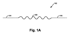
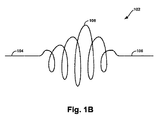
固定ガイドワイヤ(102)は、非コイル状セグメント(104)、第1の拡張可能なセグメント(106)、および先導セグメント(108)を備え、第1の拡張可能なセグメントは束縛された状態と展開された状態との間で移行するように構成される。【選択図】図1BThe fixed guidewire (102) comprises a non-coiled segment (104), a first expandable segment (106), and a leading segment (108), the first expandable segment being constrained and deployed. Configured to transition to a designated state. [Selection] Figure 1B
Description
本出願は、2014年10月14日に「Anchoring Device and Method for Use(固定デバイスおよび使用方法)」の名称で出願された米国特許仮出願第62/063,872号の非仮出願であり、その優先権を主張し、その全体が参照によって本明細書に組み込まれる。 This application is a non-provisional application of US Provisional Application No. 62 / 063,872 filed on October 14, 2014 under the name “Anchoring Device and Method for Use”; Claims its priority and is incorporated herein by reference in its entirety.
当技術分野の最先端は可変ガイドワイヤであるが、可変ガイドワイヤが展開される管腔内でその可変ガイドワイヤが能動的固定されないことがある。このような構成では、動脈瘤から生じる血管枝などの環境においてワイヤの支持がないことがあり、ガイドカテーテルをオーバーザワイヤで前進させるとき、ワイヤが標的血管から引き抜かれてしまうことがある。これにより手術は長引き、それによって患者が受ける麻酔時間は増加し、手術室の人員はより多くの放射線を受け、患者はより多くの腎毒性静脈造影剤を受けることになる。加えて標的血管に接近するワイヤを失うことにより、施術者が接近を回復できないことがあり、それにより患者は治療の結果として末端器管への灌流を有さないことがある。 Although the state of the art is a variable guidewire, the variable guidewire may not be actively secured within the lumen in which the variable guidewire is deployed. In such a configuration, the wire may not be supported in an environment such as a blood vessel branch resulting from an aneurysm, and when the guide catheter is advanced over the wire, the wire may be pulled out of the target blood vessel. This prolongs the surgery, thereby increasing the anesthesia time the patient receives, operating room personnel receiving more radiation, and the patient receiving more nephrotoxic venous contrast media. In addition, losing the wire approaching the target vessel may prevent the practitioner from regaining access, so that the patient may not have perfusion to the end organ vessel as a result of treatment.
本発明は、例えばオーバーザワイヤ型医療機器の前進および展開の前に血管系にガイドワイヤを固定するための固定デバイスを使用することにより、分岐血管内で可変ガイドワイヤの固定を向上するデバイスを対象とする。ステントグラフトを血管(またはこれに限定されないが、導管、開口部、消化管、および/もしくはあらゆる他の管状構造を含む他の管腔)内に設置できる容易性を改善することによって、複雑な症例の速度および成功率を増加させることがある一方で複雑さを低下させる。例えばガイドワイヤを被験者の血管系に固定することにより、カテーテルの先端に安定効果を有し、生体内で展開する埋め込み可能なデバイスの施術者に安定性および信頼性をより多く与えることができ得る。固定デバイスが一旦展開されると、アンカーはガイドワイヤを血管系に対して定位置に保持できる。この設計の利点の1つは、固定デバイスにより血液がアンカーを通って下流血管系に流れ続けることができることである。一旦固定されると、ガイドワイヤは、鼠径などの第1のアクセスポイントに進入し、アームなどの第2のアクセスポイントを通って出るガイドワイヤである、通しワイヤと同様に使用されてもよい。通しワイヤの利点は、両端を固定することができ、ワイヤの移動を防止し、施術者が作業する際にワイヤを支持する。同様の利点が固定ワイヤで達成できる。この固定ガイドワイヤを使用して、ベアメタルステント、カバー付きステント、ならびにあらゆる他のオーバーザワイヤデバイスなどのオーバーザワイヤ治療用医療機器の送達を改善できる。 The present invention is directed to a device that improves the fixation of a variable guidewire within a branch vessel, for example, by using a fixation device to secure the guidewire to the vasculature prior to advancement and deployment of an over-the-wire medical device And By improving the ease with which stent grafts can be placed in blood vessels (or other lumens including, but not limited to, conduits, openings, gastrointestinal tracts, and / or any other tubular structure), Reduce complexity while increasing speed and success rate. For example, by fixing a guide wire to the subject's vasculature, it can have a stabilizing effect on the tip of the catheter and can provide more stability and reliability to the practitioner of an implantable device that is deployed in vivo. . Once the fixation device is deployed, the anchor can hold the guidewire in place relative to the vasculature. One advantage of this design is that the fixation device allows blood to continue flowing through the anchor to the downstream vasculature. Once secured, the guide wire may be used in the same manner as a through wire, which is a guide wire that enters a first access point such as an inguinal and exits through a second access point such as an arm. The advantage of a through wire is that both ends can be fixed, preventing movement of the wire and supporting the wire as the practitioner works. Similar advantages can be achieved with fixed wires. This fixed guidewire can be used to improve the delivery of over-the-wire therapeutic medical devices such as bare metal stents, covered stents, and any other over-the-wire device.
したがって第1の態様では、本発明は、非コイル状セグメント、第1の拡張可能なセグメント、および先導セグメントを備えるガイドワイヤを提供し、第1の拡張可能なセグメントは束縛された状態と展開された状態との間で移行するように構成される。 Thus, in a first aspect, the present invention provides a guidewire comprising a non-coiled segment, a first expandable segment, and a leading segment, wherein the first expandable segment is deployed in a constrained state. Configured to transition to a different state.
第2態様では、本発明は、固定デバイスを管腔の中で展開するための方法も提供し、方法は、(a)本発明の第1の態様によるガイドワイヤを管腔の中に動脈アクセスを介して導入することであって、ガイドワイヤは、ガイドワイヤの第1の拡張可能なセグメントが束縛された状態にあるように、カテーテル内に配置される、導入することと、(b)第1の拡張可能なセグメントを束縛された状態から展開された状態に移行し、それによってガイドワイヤを管腔内に固定することとを含む。 In a second aspect, the present invention also provides a method for deploying a fixation device in a lumen, the method comprising: (a) providing a guidewire according to the first aspect of the present invention with an arterial access into the lumen. Introducing the guidewire, wherein the guidewire is disposed within the catheter such that the first expandable segment of the guidewire is in a constrained state; and (b) the second Transitioning one expandable segment from a constrained state to a deployed state, thereby securing the guidewire within the lumen.
例示的デバイスおよび方法が本明細書に説明される。単語「exemplary(例示的)」は本明細書では「example(例)、instance(実例)、またはillustration(説明)として機能を果たす」ことを意味するために使用されることを理解されたい。「例示的」として本明細書に説明されたあらゆる実施形態または特徴は、必ずしも他の実施形態または特徴を超えて好ましい、または有利であると解釈されるべきではない。本明細書に説明された例示的実施形態は、限定することを意味するものではない。開示されたシステムおよび方法のある特定の態様は、多種多様な異なる構成に配置し組み合わせることができ、それらのすべてが本明細書に企図されることが容易に理解されよう。 Exemplary devices and methods are described herein. It should be understood that the word “exemplary” is used herein to mean “acting as an example, instance, or illustration”. Any embodiment or feature described herein as "exemplary" is not necessarily to be construed as preferred or advantageous over other embodiments or features. The exemplary embodiments described herein are not meant to be limiting. It will be readily appreciated that certain aspects of the disclosed systems and methods can be arranged and combined in a wide variety of different configurations, all of which are contemplated herein.
さらに図に示された特定の配置は、限定と見られるべきではない。他の実施形態は、所与の図に示されたほぼそれぞれの要素を含んでもよいことを理解されたい。さらに一部の示された要素は組み合わされても、または省略されてもよい。またさらに例示的実施形態は、図に示されていない要素を含んでもよい。 Furthermore, the specific arrangement shown in the figures should not be seen as limiting. It should be understood that other embodiments may include substantially each element shown in a given figure. Furthermore, some of the illustrated elements may be combined or omitted. Still further, exemplary embodiments may include elements not shown in the figures.
本明細書で使用される場合、測定値に関して、「約」は±5%を意味する。さらに本明細書で使用される場合、「管腔」は、その中で固定デバイスが展開される血管または動脈構成を指す。用語「管腔」は例えば教育用具として使用される人工管腔をさらに含んでもよい。 As used herein, “about” with respect to a measured value means ± 5%. Further, as used herein, “lumen” refers to a vascular or arterial configuration in which a fixation device is deployed. The term “lumen” may further include an artificial lumen used, for example, as an educational tool.
第1の態様では、図1Aは束縛された状態における例示的ガイドワイヤ102を示す。図1Aに示されたように、ガイドワイヤ102は非コイル状セグメント104、拡張可能なセグメント106、および先導セグメント108を備える。非コイル状セグメント104、拡張可能なセグメント106、および先導セグメント108は概ね同軸であり、約0.01in〜約0.04inの範囲の厚さの単一ワイヤから構成されてもよい。一部の実施形態では、ガイドワイヤ102の全長は約100cm〜約500cm、好ましくは約100cm〜約300cmの範囲であってもよい。ガイドワイヤ102は、例えばニチノール(ニッケルチタン)、チタン、チタン合金、銅アルミニウム・ニッケル合金、様々なプラスチック、または形状記憶を保持できるあらゆる他の適切な材料から作成されてもよい。
In a first aspect, FIG. 1A shows an
拡張可能なセグメント106は以下の異なる2つの状態、すなわち(図1Aに示されたような)束縛された状態および(図1Bに示されたような)展開された状態のうちの1つで存在するように構成されてもよい。図1Aおよび図1Bに示されたように、拡張可能なセグメント106は展開された状態より束縛された状態において小さい直径を有する。一実施形態では、束縛された状態において、拡張可能なセグメント106は実質的に非コイル状であり、図1Dに示されたようにカテーテル110内に配置される。また展開された状態では、拡張可能なセグメント106はコイル状であり、その中にデバイスが導入される血管または管腔の壁に対して圧力を加えるように構成される。
The
一部の実施形態では、展開された状態にあるとき、拡張可能なセグメント106は、血管または管腔に対して約0.25ATM〜約3.0ATM、好ましくは約0.5ATM〜約1.5ATMの範囲であってもよい圧力を加えてもよい。拡張可能な部分106によって血管または管腔に対して加えられた圧力は、圧力が血管または管腔を切断しないように実質的に小さくなければならないが、ガイドワイヤが血管または管腔から滑り出ないように適正な量の固定を提供する充分な大きさであるべきである。展開された状態において、拡張可能なセグメント106は約10mm〜約100mmの範囲の長さ、および拡張された直径で約1mm〜約80mmの範囲を有してもよい。一例では、展開された状態において拡張可能なセグメント106の拡張された直径は、その中でデバイスが展開される管腔の直径より約20%を超える大きさであってもよい。一部の実施形態では、拡張可能なセグメント106の異なる部分は、異なる圧力を加えてもよい。例えば拡張可能なセグメント106の一部はよりきつく巻かれたコイルであり、それによって拡張可能なセグメント106の他の部分より多くの圧力を血管壁に加えてもよい。別の配置では、拡張可能なセグメント106の一部のコイルはより大きい直径を有してもよく、したがって拡張可能なセグメント106の別の部分のコイルより多くの圧力を血管壁に加えてもよい。別の配置では、拡張可能なセグメント106の一部は、拡張可能なセグメント106の他の部分より多くの圧力を血管壁に加えてもよい、より大きい厚さのワイヤから構成されてもよい。なお別の配置では、拡張可能なセグメント106の一部のコイルは、拡張可能なセグメント106の別の部分のコイルと異なるピッチであってもよい。したがって拡張可能なセグメント106の一部は他の部分と異なる圧力を血管壁に加えてもよい。しかし他の配置では、拡張可能なセグメント106のそれぞれの部分は、その他の部分と実質的に同じ圧力を加えてもよい。
In some embodiments, when in the expanded state, the
先導セグメント108は、固定デバイス100を(束縛された状態の間に)管腔を通って適切な展開位置に導く助けとなるために、拡張可能なセグメント106を超えて延在してもよい。加えて先導セグメント108は、先導セグメント108が接触する管腔の部分への不注意な損傷を軽減するように、形状されるかまたは構成されてもよい。例えば先導セグメント108の遠位端は特に丸みを帯びるか、または平滑にされてもよい。加えてまたは別法として、先導セグメント108はデバイスの他の部分より堅くないまたは他の従来の生体材料より堅くない、適合した材料から構成されてもよい。したがって先導セグメント108は「非侵襲的」であるとみなされてもよい。先導セグメント108は、実質的に直線でありガイドワイヤ102をより容易にカテーテルに装填させるという点で、追加の利点を有する。実質的に直線の先導セグメント108により、ガイドワイヤ102をカテーテルの中に装填する施術者は、拡張可能なセグメント106を前進させる前にカテーテルにガイドワイヤ102を装填することができる。また先導セグメント108は、カテーテルを通ってガイドワイヤ102を容易に前進させる。先導セグメント108の末端までコイル状であったら、コイルの性質により先端がカテーテルの内面に押し込まれ、ワイヤの前進が困難になるだろう。そうではなく実質的に直線の先導セグメント108は、施術者がより容易にガイドワイヤ102を所望の場所に導くことを可能にする。先導セグメント108は、ガイドワイヤ102が展開された状態であるときでさえ、血管または管腔の壁が先導セグメント108に作用しない限り実質的に直線のままである。したがって先導セグメント108は形状記憶材料から構成される必要がない。一部の例では、先導セグメント108は拡張可能なセグメント106より約2mm〜約200mm、好ましくは約3mm〜約50mm長く延在してもよい。しかし他の例も可能である。
The leading
図1Cは、本発明の一実施形態により展開された状態における別の固定デバイスの側面図である。図1Cに示されたように、ガイドワイヤ102は、非コイル状セグメント104と拡張可能なセグメント106との間に位置付けられた、第2の拡張可能なセグメント107をさらに含んでもよい。第2の拡張可能なセグメント107は、拡張可能なセグメント106と同様に束縛された状態と展開された状態との間で移行するように構成されてもよい。束縛された状態では、第2の拡張可能なセグメント107はカテーテル内に配置されてもよい。一実施形態では、第2の拡張可能なセグメント107は、その中にデバイスが配置される管腔に圧力を加えるように構成された、第2のコイル状ワイヤとして配置される。一部の実施形態では、第1の拡張可能なセグメント106および第2の拡張可能なセグメント107は、管腔に同じ圧力を加えるように配置されるが、他の実施形態では、第1の拡張可能なセグメント106は、第2の拡張可能なセグメント107と異なる圧力を管腔に加えるように配置される。他の例も同様に可能である。
FIG. 1C is a side view of another fixation device in a deployed state according to an embodiment of the present invention. As shown in FIG. 1C, the
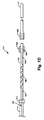
図1Dはカテーテル110内に配置された固定デバイス100を示す。束縛された状態と展開された状態との間で移行するために、カテーテル110は非コイル状セグメント104に向かって後方に摺動し、それによって拡張可能なセグメント106が血管系に露出され、拡張可能なセグメント106が拡張してコイル状になることができ、それによって血管壁に外方への力を加えてもよい。代替実装形態では、デバイス100は、拡張可能なセグメント106を同じ方法で前進させて露出するために、カテーテル110を通って押されてもよい。同様に展開された状態から束縛された状態に移行するために、カテーテル110は拡張可能なセグメント106の上で押し戻されてもよく、または別法として、拡張可能なセグメント106はカテーテル110を通って引き戻されてもよい。さらに別の例では、拡張可能なセグメント106は、同時に拡張可能なセグメント106をカテーテル110から出て摺動させ、カテーテル110を拡張可能なセグメント106の上で摺動させることにより、束縛された状態と展開された状態との間で移行するように構成される。
FIG. 1D shows the fixation device 100 positioned within the
一部の実施形態では、カテーテル110は送達カテーテル部112および接触カテーテル部114を備える。送達カテーテル部112は直線または可変ガイドワイヤの上で標的血管または管腔の中に前進させてもよい。したがって送達カテーテルは実質的に生体内カテーテルである。直線または可変ガイドワイヤが一旦取り除かれると、送達カテーテル112は標的血管または管腔内の適所にあり、接触カテーテル114を取り付けることができ、ガイドワイヤ102は送達カテーテル112を通って標的血管または管腔に前進することができる。したがって接触カテーテル114は実質的に体外にとどまってもよく、展開する前にガイドワイヤ102を収納するために使用されてもよい。したがって拡張可能なセグメント106および先導セグメント108は、使用前に接触カテーテル部114内に配置されてもよい。送達カテーテル部112は、送達カテーテル部112が接触する管腔の部分への不注意な損傷を軽減するように、形状または構成されてもよい。例えば送達カテーテル部112の先端は特に丸みを帯びるか、または平滑にされてもよい。加えてまたは別法として、送達カテーテル部112はデバイスの他の部分より堅くないか、または他の従来の生体材料より堅くない、適合した材料から構成されてもよい。
In some embodiments, the
使用前に非コイル状セグメント104は、ハウジング111内に位置付けられてもよい。ハウジング111は例えばプラスチック材料であってもよい。ハウジング111は係止/係脱ハブ113を介して接触カテーテル114に結合されてもよい。作動中に接触カテーテル114は、補完的ルアーロックコネクタ116A、116B、ねじ込み式コネクタ、または他の何らかのタイプのコネクタを介して送達カテーテル112に結合されてもよい。接触カテーテル114が送達カテーテル112に一旦結合されると、ハウジング111は係止/係脱ハブ113から分離され、ガイドワイヤ102の非コイル状セグメント104の周囲から取り除かれてもよい。一旦接触カテーテル114が送達カテーテル112に連結され、ハウジング111が取り除かれると、接触カテーテル114の先導縁部上の弁109を開くことができ、それによって施術者がガイドワイヤ102の非コイル状セグメント104を操作でき、それによってガイドワイヤ102は接触カテーテル114を通って前進し、送達カテーテル112の中に入り、最終的に標的血管または管腔に達することができる。
Prior to use, the
図1Eは、管腔118の中に導入された固定デバイスの詳細な断側面図を示す。一実施形態によると、デバイス100を管腔内に導入するために、最初に標準ガイドワイヤが動脈アクセスを介して管腔118の中に導入されてもよい。2番目に、送達カテーテル112は、送達カテーテル112が所望の場所に位置するまで、標準ガイドワイヤの上で管腔118の中を前進してもよい。この時点で標準ガイドワイヤは取り除かれてもよい。3番目に、接触カテーテル114は体外で送達カテーテル112の端部に結合されてもよい(しかし一部の実施形態では、接触カテーテル114はこの時点ですでに送達カテーテル部112に結合されていてもよい)。4番目に、ガイドワイヤ102の拡張可能なセグメント106および先導セグメント108は、接触カテーテル114および送達カテーテル112を通って前進し、それによって図1Eに示されたように、管腔118内の所望の場所で拡張可能なセグメント106を展開する。5番目に、送達カテーテル112は図1Eに示されたように管腔118から取り除かれ、ガイドワイヤ102は適切な位置に残る。6番目に、その送達カテーテルとともにステントなどの治療用および/または埋め込み可能なデバイスは、ガイドワイヤ102の非コイル状セグメント104の上で所望の治療場所に前進する。ほぼ上述のステップ、または上述と異なる順番のステップに関与する一部の構成を含む、他の構成も同様に可能であることが理解されよう。
FIG. 1E shows a detailed cross-sectional side view of the fixation device introduced into the
図2は、例示的実施形態による方法を示す簡略化した流れ図である。ブロックは連続した順番に示されているが、これらのブロックは並行しても、かつ/または本明細書に説明されたものと異なる順番で実行されてもよい。また様々なブロックが、より少ないブロックに組み合わされても、さらなるブロックに分けられても、かつ/または所望の実装形態に基づいて取り除かれてもよい。 FIG. 2 is a simplified flow diagram illustrating a method according to an exemplary embodiment. Although the blocks are shown in a sequential order, these blocks may be executed in parallel and / or in a different order than that described herein. The various blocks may also be combined into fewer blocks, divided into further blocks, and / or removed based on the desired implementation.
ブロック202では、方法は、上述の固定デバイスを管腔の中に動脈アクセスを介して導入するものであり、固定デバイスのガイドワイヤは、拡張可能なセグメントが束縛された状態にあるようにカテーテル内に配置される。固定デバイスは、拡張可能なセグメントが実質的に非コイル構成でカテーテル内に配置された束縛された状態で、拡張可能なセグメントを備えた既に配置されたガイドワイヤの上で管腔の中に導入されてもよい。一例では、管腔の中にデバイスを導入することには、動脈アクセスを介して管腔の中に送達カテーテルを導入することが含まれ、送達カテーテルは、その中に非コイル状セグメント、第1の拡張可能なセグメント、および先導セグメントを備えるガイドワイヤが配置された接触カテーテルに結合される。このような例では、接触カテーテルは、ルアーロックコネクタ、ねじ込み式コネクタ、または他の何らかのタイプのコネクタを介して送達カテーテル部に結合されてもよい。接触カテーテルが送達カテーテルに一旦連結されると、接触カテーテルの先導縁部上の弁を開くことができることにより、固定ワイヤが接触カテーテルを通って送達カテーテルの中を前進することができる。
At
ブロック204では、方法は拡張可能なセグメントを束縛された状態から展開された状態に移行し、それによってガイドワイヤを管腔内に固定するものである。上述のように、拡張可能なセグメントを束縛された状態から展開された状態に移行することは、カテーテルから出て拡張可能なセグメントを摺動させること、または別法としてもしくは同時にカテーテルを拡張可能なセグメントの上で摺動させて戻すことを含んでもよい。拡張可能なセグメントは展開された状態に露出される際に、拡張可能なセグメントは形状記憶に起因してコイル状になり、拡張してもよく、それによって管腔上に圧力を加える。拡張可能なセグメントが血管壁に接触する拡張した状態で管腔上に加えられる圧力は、約0.25ATM〜約3.0ATMの範囲であってもよい。さらに上述のように、拡張可能なセグメントは、拡張可能なセグメントの第1の部分が拡張可能なセグメントの第2の部分と異なる圧力を加えるように、管腔上に段階的に圧力を加えてもよい。代替実施形態では、拡張可能なセグメントの各部分は、管腔上に実質的に同じ圧力を加えてもよい。
At
方法は、管腔からカテーテルを取り除く一方でガイドワイヤを背後に残すこと、およびステントなどの治療用および/または埋め込み可能なデバイスをガイドワイヤの非コイル状セグメントの上で所望の治療場所に導入することをさらに含んでもよい。ほぼ上述のステップ、または上述と異なる順番のステップに関与する一部の構成を含む、他の構成も同様に可能であることが理解されよう。 The method removes the catheter from the lumen while leaving the guidewire behind, and introduces a therapeutic and / or implantable device, such as a stent, over the non-coiled segment of the guidewire to the desired treatment location. It may further include. It will be appreciated that other configurations are possible as well, including some configurations that are generally involved in the steps described above or in a different order than described above.
様々な態様および実施形態が本明細書に説明されたが、他の態様および実施形態が当業者には明らかになろう。文脈が明確にそうでないと指定しない限り、本発明の異なる態様内および異なる態様ごとにおいてすべての実施形態を組み合わせることができる。本明細書に開示された様々な態様および実施形態は説明のためであり、限定を企図するものではなく、真の範囲および精神は以下の特許請求の範囲に示されている。 While various aspects and embodiments have been described herein, other aspects and embodiments will be apparent to those skilled in the art. Unless the context clearly dictates otherwise, all embodiments can be combined within and within different aspects of the invention. The various aspects and embodiments disclosed herein are for purposes of illustration and are not intended to be limiting, with the true scope and spirit being indicated by the following claims.
Claims (43)
接触カテーテルと、
前記接触カテーテルに結合された送達カテーテルと
を備える、請求項22〜請求項24のいずれかに記載のガイドワイヤ。 The catheter is
A contact catheter;
25. A guide wire according to any of claims 22 to 24, comprising a delivery catheter coupled to the contact catheter.
前記第1の拡張可能なセグメントを前記束縛された状態から展開された状態に移行し、それによって前記ガイドワイヤを前記管腔内で固定することと
を含む、方法。 25. Introducing a guidewire according to any one of claims 1 to 24 into a lumen via arterial access, the guidewire being constrained by a first expandable segment. Introducing into a catheter so that
Transitioning the first expandable segment from the constrained state to a deployed state, thereby securing the guidewire within the lumen.
送達カテーテルを管腔内に動脈アクセスを介して導入することを含み、前記送達カテーテルは、その中に非コイル状セグメント、第1の拡張可能なセグメント、および先導セグメントを備えるガイドワイヤが配置された接触カテーテルに結合される、請求項26〜請求項30のいずれかに記載の方法。 Introducing the guidewire of any one of claims 1 to 25 into a lumen via arterial access;
Introducing a delivery catheter into the lumen via arterial access, the delivery catheter having a non-coiled segment, a first expandable segment, and a guidewire with a leading segment disposed therein 31. A method according to any of claims 26 to 30 coupled to a contact catheter.
前記第1の拡張可能なセグメントが前記接触カテーテルを通り、前記送達カテーテルを通り、前記送達カテーテルから出て摺動させることと、
前記接触カテーテルおよび前記送達カテーテルを前記第1の拡張可能なセグメントの上で摺動させることの少なくとも1つを含む、請求項31に記載の方法。 Transitioning the first expandable segment from the constrained state to an expanded state,
Sliding said first expandable segment through said contact catheter, through said delivery catheter and out of said delivery catheter;
32. The method of claim 31, comprising at least one of sliding the contact catheter and the delivery catheter over the first expandable segment.
治療用デバイスを前記非コイル状セグメントの上に前記管腔を介して導入することと
をさらに含む、請求項26〜請求項41のいずれかに記載の方法。 Removing the catheter from the lumen;
42. A method according to any of claims 26 to 41, further comprising introducing a therapeutic device over the non-coiled segment via the lumen.
Applications Claiming Priority (3)
| Application Number | Priority Date | Filing Date | Title |
|---|---|---|---|
| US201462063872P | 2014-10-14 | 2014-10-14 | |
| US62/063,872 | 2014-10-14 | ||
| PCT/US2015/055513 WO2016061213A1 (en) | 2014-10-14 | 2015-10-14 | Anchoring guidewire |
Publications (1)
| Publication Number | Publication Date |
|---|---|
| JP2017534314A true JP2017534314A (en) | 2017-11-24 |
Family
ID=54396966
Family Applications (1)
| Application Number | Title | Priority Date | Filing Date |
|---|---|---|---|
| JP2017512728A Pending JP2017534314A (en) | 2014-10-14 | 2015-10-14 | Fixed guide wire |
Country Status (6)
| Country | Link |
|---|---|
| US (1) | US20160101267A1 (en) |
| EP (1) | EP3206743A1 (en) |
| JP (1) | JP2017534314A (en) |
| AU (1) | AU2015332550A1 (en) |
| CA (1) | CA2962811A1 (en) |
| WO (1) | WO2016061213A1 (en) |
Families Citing this family (6)
| Publication number | Priority date | Publication date | Assignee | Title |
|---|---|---|---|---|
| US9682216B2 (en) | 2014-12-05 | 2017-06-20 | Anchor Endovascular, Inc. | Anchor device for use with catheters |
| JP6983822B2 (en) * | 2016-06-23 | 2021-12-17 | アヴェント インコーポレイテッド | Echo source coil member for catheter assembly |
| CA3043614A1 (en) * | 2016-11-10 | 2018-05-17 | Eva Innovations | Insertion device for one-handed insertion of a guidewire into the lumen of a vessel/cavity |
| WO2019046352A1 (en) * | 2017-08-30 | 2019-03-07 | Sanford Health | Anchoring guide wire and methods for use thereof |
| US11324930B2 (en) | 2018-02-08 | 2022-05-10 | Boston Scientific Scimed, Inc. | Medical guidewires with controllable features |
| WO2023081640A1 (en) * | 2021-11-02 | 2023-05-11 | The Board Of Trustees Of The University Of Illinois | Spiral endovascular guide wire |
Family Cites Families (6)
| Publication number | Priority date | Publication date | Assignee | Title |
|---|---|---|---|---|
| US5054501A (en) * | 1990-05-16 | 1991-10-08 | Brigham & Women's Hospital | Steerable guide wire for cannulation of tubular or vascular organs |
| US6371928B1 (en) * | 1997-11-07 | 2002-04-16 | Prolifix Medical, Inc. | Guidewire for positioning a catheter against a lumen wall |
| US7670302B2 (en) * | 2001-12-18 | 2010-03-02 | Boston Scientific Scimed, Inc. | Super elastic guidewire with shape retention tip |
| US20030191492A1 (en) * | 2002-04-05 | 2003-10-09 | Scimed Life Systems, Inc. | Radial coil expandable medical wire |
| CN103533983A (en) * | 2011-03-30 | 2014-01-22 | 康奈尔大学 | Intra-luminal access apparatus and methods of using the same |
| WO2014138513A1 (en) * | 2013-03-08 | 2014-09-12 | The Cleveland Clinic Foundation | Exchange guidewire |
-
2015
- 2015-10-14 US US14/883,259 patent/US20160101267A1/en not_active Abandoned
- 2015-10-14 JP JP2017512728A patent/JP2017534314A/en active Pending
- 2015-10-14 WO PCT/US2015/055513 patent/WO2016061213A1/en active Application Filing
- 2015-10-14 EP EP15790339.4A patent/EP3206743A1/en not_active Withdrawn
- 2015-10-14 AU AU2015332550A patent/AU2015332550A1/en not_active Abandoned
- 2015-10-14 CA CA2962811A patent/CA2962811A1/en not_active Abandoned
Also Published As
| Publication number | Publication date |
|---|---|
| AU2015332550A1 (en) | 2017-03-23 |
| CA2962811A1 (en) | 2016-04-21 |
| WO2016061213A1 (en) | 2016-04-21 |
| EP3206743A1 (en) | 2017-08-23 |
| US20160101267A1 (en) | 2016-04-14 |
Similar Documents
| Publication | Publication Date | Title |
|---|---|---|
| JP2017534314A (en) | Fixed guide wire | |
| US20210169670A1 (en) | Stent cannulation guiding device for bifurcated stent and method of use | |
| US11478235B2 (en) | Closure apparatus with flexible sealable member and flexible support member | |
| JP6172704B2 (en) | Apparatus and method for prevention of stenosis at the site of anastomosis | |
| US20170028170A1 (en) | Guide catheter extension device and methods of use for cardiology procedures | |
| AU2018247301A1 (en) | Braided stent with expansion ring and method of delivery | |
| US9622894B2 (en) | Apparatus for implanting a device | |
| JP2018008103A (en) | Anastomotic connector and system for delivery | |
| US9066793B2 (en) | Method of implanting an aortic stent | |
| JP5866131B2 (en) | Anastomotic connector | |
| JP2015531283A (en) | Method and device for blocking flow during device replacement | |
| JP2014518684A (en) | Guide wire having two flexible end portions and method for accessing a branch vessel using the same | |
| JP5074502B2 (en) | Self-expanding stent system for bifurcated damage | |
| AU2021232667A1 (en) | Stent cannulation guiding device and method of use | |
| US20120123526A1 (en) | Thoracic aortic stent structure | |
| JP5259593B2 (en) | Vascular prosthesis and delivery device | |
| US20140039598A1 (en) | Blood loss control system | |
| WO2015094703A1 (en) | Deflector for increased wall shear stress adjacent an arteriovenous fistula | |
| WO2019046352A1 (en) | Anchoring guide wire and methods for use thereof | |
| CN112043458A (en) | Aorta interlayer covered stent windowing external member | |
| WO2014022213A1 (en) | Expandable graft and associated methods for deployment | |
| US20110295357A1 (en) | Abdominal Aortic Stent |