JP2017533764A - Method for imparting decorative design and structural features to footwear articles - Google Patents
Method for imparting decorative design and structural features to footwear articles Download PDFInfo
- Publication number
- JP2017533764A JP2017533764A JP2017524397A JP2017524397A JP2017533764A JP 2017533764 A JP2017533764 A JP 2017533764A JP 2017524397 A JP2017524397 A JP 2017524397A JP 2017524397 A JP2017524397 A JP 2017524397A JP 2017533764 A JP2017533764 A JP 2017533764A
- Authority
- JP
- Japan
- Prior art keywords
- laser
- midsole
- color
- applying
- depth
- Prior art date
- Legal status (The legal status is an assumption and is not a legal conclusion. Google has not performed a legal analysis and makes no representation as to the accuracy of the status listed.)
- Withdrawn
Links
- 238000000034 method Methods 0.000 title claims abstract description 102
- 238000013461 design Methods 0.000 title abstract description 37
- 239000000463 material Substances 0.000 claims description 105
- 230000008859 change Effects 0.000 claims description 51
- 230000000873 masking effect Effects 0.000 claims description 45
- 239000003086 colorant Substances 0.000 claims description 26
- 239000012530 fluid Substances 0.000 claims description 25
- 238000001035 drying Methods 0.000 claims description 12
- XLYOFNOQVPJJNP-UHFFFAOYSA-N water Substances O XLYOFNOQVPJJNP-UHFFFAOYSA-N 0.000 claims description 11
- 239000000654 additive Substances 0.000 claims description 10
- 230000007704 transition Effects 0.000 claims description 9
- 239000007864 aqueous solution Substances 0.000 claims description 8
- 239000000243 solution Substances 0.000 claims description 8
- 238000005406 washing Methods 0.000 claims description 8
- 230000000996 additive effect Effects 0.000 claims description 6
- 238000004140 cleaning Methods 0.000 claims description 6
- 230000001681 protective effect Effects 0.000 claims description 5
- 239000004094 surface-active agent Substances 0.000 claims description 4
- 238000004519 manufacturing process Methods 0.000 abstract description 20
- 239000003973 paint Substances 0.000 description 31
- 230000000386 athletic effect Effects 0.000 description 13
- 238000004040 coloring Methods 0.000 description 12
- 230000008569 process Effects 0.000 description 12
- 210000000452 mid-foot Anatomy 0.000 description 11
- 238000010147 laser engraving Methods 0.000 description 10
- 238000010422 painting Methods 0.000 description 10
- 238000012545 processing Methods 0.000 description 10
- 230000001680 brushing effect Effects 0.000 description 9
- 229920001971 elastomer Polymers 0.000 description 9
- 210000002683 foot Anatomy 0.000 description 9
- 239000007788 liquid Substances 0.000 description 9
- 239000005038 ethylene vinyl acetate Substances 0.000 description 8
- 210000004744 fore-foot Anatomy 0.000 description 8
- DQXBYHZEEUGOBF-UHFFFAOYSA-N but-3-enoic acid;ethene Chemical compound C=C.OC(=O)CC=C DQXBYHZEEUGOBF-UHFFFAOYSA-N 0.000 description 7
- 238000000576 coating method Methods 0.000 description 7
- 238000010330 laser marking Methods 0.000 description 7
- 239000010410 layer Substances 0.000 description 7
- 229920001200 poly(ethylene-vinyl acetate) Polymers 0.000 description 7
- 239000005060 rubber Substances 0.000 description 7
- 238000005507 spraying Methods 0.000 description 7
- 230000008901 benefit Effects 0.000 description 5
- 239000012459 cleaning agent Substances 0.000 description 5
- 230000006835 compression Effects 0.000 description 5
- 238000007906 compression Methods 0.000 description 5
- 238000010438 heat treatment Methods 0.000 description 5
- 239000000344 soap Substances 0.000 description 5
- IJGRMHOSHXDMSA-UHFFFAOYSA-N Atomic nitrogen Chemical compound N#N IJGRMHOSHXDMSA-UHFFFAOYSA-N 0.000 description 4
- 229920000459 Nitrile rubber Polymers 0.000 description 4
- 238000002679 ablation Methods 0.000 description 4
- 239000011248 coating agent Substances 0.000 description 4
- 238000005520 cutting process Methods 0.000 description 4
- 238000003618 dip coating Methods 0.000 description 4
- 238000007598 dipping method Methods 0.000 description 4
- 238000000465 moulding Methods 0.000 description 4
- 238000007493 shaping process Methods 0.000 description 4
- 210000003371 toe Anatomy 0.000 description 4
- 239000000853 adhesive Substances 0.000 description 3
- 230000001070 adhesive effect Effects 0.000 description 3
- 238000009826 distribution Methods 0.000 description 3
- 239000000835 fiber Substances 0.000 description 3
- 239000000945 filler Substances 0.000 description 3
- 229920000642 polymer Polymers 0.000 description 3
- 238000012805 post-processing Methods 0.000 description 3
- 239000007787 solid Substances 0.000 description 3
- 239000000126 substance Substances 0.000 description 3
- XKRFYHLGVUSROY-UHFFFAOYSA-N Argon Chemical compound [Ar] XKRFYHLGVUSROY-UHFFFAOYSA-N 0.000 description 2
- 239000004709 Chlorinated polyethylene Substances 0.000 description 2
- 239000004698 Polyethylene Substances 0.000 description 2
- 239000004433 Thermoplastic polyurethane Substances 0.000 description 2
- 230000004913 activation Effects 0.000 description 2
- 230000001154 acute effect Effects 0.000 description 2
- 239000002131 composite material Substances 0.000 description 2
- 238000001816 cooling Methods 0.000 description 2
- 238000005034 decoration Methods 0.000 description 2
- 230000000694 effects Effects 0.000 description 2
- 239000000806 elastomer Substances 0.000 description 2
- 238000005530 etching Methods 0.000 description 2
- 239000004744 fabric Substances 0.000 description 2
- 230000006870 function Effects 0.000 description 2
- 239000007789 gas Substances 0.000 description 2
- 238000010348 incorporation Methods 0.000 description 2
- 238000007373 indentation Methods 0.000 description 2
- 239000011261 inert gas Substances 0.000 description 2
- 230000007246 mechanism Effects 0.000 description 2
- 239000000203 mixture Substances 0.000 description 2
- 229910052757 nitrogen Inorganic materials 0.000 description 2
- 230000002093 peripheral effect Effects 0.000 description 2
- 239000000049 pigment Substances 0.000 description 2
- 229920000573 polyethylene Polymers 0.000 description 2
- 229920001169 thermoplastic Polymers 0.000 description 2
- 229920002725 thermoplastic elastomer Polymers 0.000 description 2
- 229920002803 thermoplastic polyurethane Polymers 0.000 description 2
- 239000004416 thermosoftening plastic Substances 0.000 description 2
- 230000000007 visual effect Effects 0.000 description 2
- 238000010146 3D printing Methods 0.000 description 1
- 235000009854 Cucurbita moschata Nutrition 0.000 description 1
- 240000001980 Cucurbita pepo Species 0.000 description 1
- 235000009852 Cucurbita pepo Nutrition 0.000 description 1
- 241000272183 Geococcyx californianus Species 0.000 description 1
- 239000005062 Polybutadiene Substances 0.000 description 1
- 208000012287 Prolapse Diseases 0.000 description 1
- 229920003182 Surlyn® Polymers 0.000 description 1
- 230000009471 action Effects 0.000 description 1
- 238000007605 air drying Methods 0.000 description 1
- 238000004458 analytical method Methods 0.000 description 1
- 210000003423 ankle Anatomy 0.000 description 1
- 229910052786 argon Inorganic materials 0.000 description 1
- 230000037147 athletic performance Effects 0.000 description 1
- 239000012298 atmosphere Substances 0.000 description 1
- 230000006399 behavior Effects 0.000 description 1
- 230000009286 beneficial effect Effects 0.000 description 1
- 230000003139 buffering effect Effects 0.000 description 1
- 239000003795 chemical substances by application Substances 0.000 description 1
- 239000011247 coating layer Substances 0.000 description 1
- 238000000748 compression moulding Methods 0.000 description 1
- 239000002826 coolant Substances 0.000 description 1
- 230000001351 cycling effect Effects 0.000 description 1
- 238000013500 data storage Methods 0.000 description 1
- 238000002845 discoloration Methods 0.000 description 1
- 239000006185 dispersion Substances 0.000 description 1
- 230000005611 electricity Effects 0.000 description 1
- 238000011010 flushing procedure Methods 0.000 description 1
- 239000006260 foam Substances 0.000 description 1
- 239000006261 foam material Substances 0.000 description 1
- 238000010097 foam moulding Methods 0.000 description 1
- 230000002209 hydrophobic effect Effects 0.000 description 1
- 238000005286 illumination Methods 0.000 description 1
- 230000006872 improvement Effects 0.000 description 1
- 230000001788 irregular Effects 0.000 description 1
- 229920003049 isoprene rubber Polymers 0.000 description 1
- 230000009191 jumping Effects 0.000 description 1
- 210000003127 knee Anatomy 0.000 description 1
- 230000000670 limiting effect Effects 0.000 description 1
- 210000001872 metatarsal bone Anatomy 0.000 description 1
- 230000004048 modification Effects 0.000 description 1
- 238000012986 modification Methods 0.000 description 1
- 230000003287 optical effect Effects 0.000 description 1
- 230000007170 pathology Effects 0.000 description 1
- 238000006552 photochemical reaction Methods 0.000 description 1
- 230000000704 physical effect Effects 0.000 description 1
- 230000036314 physical performance Effects 0.000 description 1
- 239000002985 plastic film Substances 0.000 description 1
- 229920006255 plastic film Polymers 0.000 description 1
- -1 polyethylene Polymers 0.000 description 1
- 239000002861 polymer material Substances 0.000 description 1
- 239000004814 polyurethane Substances 0.000 description 1
- 239000011253 protective coating Substances 0.000 description 1
- 239000011241 protective layer Substances 0.000 description 1
- 230000002829 reductive effect Effects 0.000 description 1
- 238000000110 selective laser sintering Methods 0.000 description 1
- 239000004065 semiconductor Substances 0.000 description 1
- 230000035939 shock Effects 0.000 description 1
- 239000008149 soap solution Substances 0.000 description 1
- 235000020354 squash Nutrition 0.000 description 1
- 230000000087 stabilizing effect Effects 0.000 description 1
- 230000003068 static effect Effects 0.000 description 1
- 230000003746 surface roughness Effects 0.000 description 1
- 239000004753 textile Substances 0.000 description 1
- 210000001519 tissue Anatomy 0.000 description 1
- 238000009423 ventilation Methods 0.000 description 1
- 239000002699 waste material Substances 0.000 description 1
- 230000037303 wrinkles Effects 0.000 description 1
- 238000004383 yellowing Methods 0.000 description 1
Images


Classifications
-
- A—HUMAN NECESSITIES
- A43—FOOTWEAR
- A43D—MACHINES, TOOLS, EQUIPMENT OR METHODS FOR MANUFACTURING OR REPAIRING FOOTWEAR
- A43D95/00—Shoe-finishing machines
- A43D95/14—Shoe-finishing machines incorporating marking, printing, or embossing apparatus
-
- A—HUMAN NECESSITIES
- A43—FOOTWEAR
- A43D—MACHINES, TOOLS, EQUIPMENT OR METHODS FOR MANUFACTURING OR REPAIRING FOOTWEAR
- A43D8/00—Machines for cutting, ornamenting, marking or otherwise working up shoe part blanks
- A43D8/16—Ornamentation
-
- A—HUMAN NECESSITIES
- A43—FOOTWEAR
- A43B—CHARACTERISTIC FEATURES OF FOOTWEAR; PARTS OF FOOTWEAR
- A43B23/00—Uppers; Boot legs; Stiffeners; Other single parts of footwear
- A43B23/24—Ornamental buckles; Other ornaments for shoes without fastening function
-
- A—HUMAN NECESSITIES
- A43—FOOTWEAR
- A43B—CHARACTERISTIC FEATURES OF FOOTWEAR; PARTS OF FOOTWEAR
- A43B3/00—Footwear characterised by the shape or the use
- A43B3/0036—Footwear characterised by the shape or the use characterised by a special shape or design
- A43B3/0078—Footwear characterised by the shape or the use characterised by a special shape or design provided with logos, letters, signatures or the like decoration
-
- A—HUMAN NECESSITIES
- A43—FOOTWEAR
- A43D—MACHINES, TOOLS, EQUIPMENT OR METHODS FOR MANUFACTURING OR REPAIRING FOOTWEAR
- A43D8/00—Machines for cutting, ornamenting, marking or otherwise working up shoe part blanks
- A43D8/16—Ornamentation
- A43D8/22—Ornamentation by embossing or printing
-
- A—HUMAN NECESSITIES
- A43—FOOTWEAR
- A43D—MACHINES, TOOLS, EQUIPMENT OR METHODS FOR MANUFACTURING OR REPAIRING FOOTWEAR
- A43D8/00—Machines for cutting, ornamenting, marking or otherwise working up shoe part blanks
- A43D8/26—Marking for future work
- A43D8/28—Patterns for drawing cut-outs
-
- A—HUMAN NECESSITIES
- A43—FOOTWEAR
- A43D—MACHINES, TOOLS, EQUIPMENT OR METHODS FOR MANUFACTURING OR REPAIRING FOOTWEAR
- A43D95/00—Shoe-finishing machines
- A43D95/06—Machines for colouring or chemical treatment; Ornamenting the sole bottoms
-
- B—PERFORMING OPERATIONS; TRANSPORTING
- B23—MACHINE TOOLS; METAL-WORKING NOT OTHERWISE PROVIDED FOR
- B23K—SOLDERING OR UNSOLDERING; WELDING; CLADDING OR PLATING BY SOLDERING OR WELDING; CUTTING BY APPLYING HEAT LOCALLY, e.g. FLAME CUTTING; WORKING BY LASER BEAM
- B23K26/00—Working by laser beam, e.g. welding, cutting or boring
- B23K26/36—Removing material
- B23K26/361—Removing material for deburring or mechanical trimming
-
- B—PERFORMING OPERATIONS; TRANSPORTING
- B23—MACHINE TOOLS; METAL-WORKING NOT OTHERWISE PROVIDED FOR
- B23K—SOLDERING OR UNSOLDERING; WELDING; CLADDING OR PLATING BY SOLDERING OR WELDING; CUTTING BY APPLYING HEAT LOCALLY, e.g. FLAME CUTTING; WORKING BY LASER BEAM
- B23K26/00—Working by laser beam, e.g. welding, cutting or boring
- B23K26/36—Removing material
- B23K26/38—Removing material by boring or cutting
- B23K26/382—Removing material by boring or cutting by boring
-
- A—HUMAN NECESSITIES
- A43—FOOTWEAR
- A43B—CHARACTERISTIC FEATURES OF FOOTWEAR; PARTS OF FOOTWEAR
- A43B13/00—Soles; Sole-and-heel integral units
- A43B13/14—Soles; Sole-and-heel integral units characterised by the constructive form
-
- A—HUMAN NECESSITIES
- A43—FOOTWEAR
- A43B—CHARACTERISTIC FEATURES OF FOOTWEAR; PARTS OF FOOTWEAR
- A43B13/00—Soles; Sole-and-heel integral units
- A43B13/14—Soles; Sole-and-heel integral units characterised by the constructive form
- A43B13/141—Soles; Sole-and-heel integral units characterised by the constructive form with a part of the sole being flexible, e.g. permitting articulation or torsion
-
- A—HUMAN NECESSITIES
- A43—FOOTWEAR
- A43B—CHARACTERISTIC FEATURES OF FOOTWEAR; PARTS OF FOOTWEAR
- A43B13/00—Soles; Sole-and-heel integral units
- A43B13/14—Soles; Sole-and-heel integral units characterised by the constructive form
- A43B13/22—Soles made slip-preventing or wear-resisting, e.g. by impregnation or spreading a wear-resisting layer
- A43B13/223—Profiled soles
Landscapes
- Engineering & Computer Science (AREA)
- Physics & Mathematics (AREA)
- Optics & Photonics (AREA)
- Plasma & Fusion (AREA)
- Mechanical Engineering (AREA)
- Footwear And Its Accessory, Manufacturing Method And Apparatuses (AREA)
- Laser Beam Processing (AREA)
Abstract
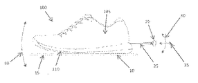
本発明は、構造的特徴及び装飾的デザインを有する履物及びその一部分に関し、これを製造するためのシステム及び方法に関する。物体の表面上に特徴を付与するための例示的な方法は、物体の表面近傍にレーザ(20)を位置決めするステップと、レーザ(20)から物体の表面にレーザビーム(25)を誘導し、物体の表面の少なくとも一部分にマーキングする又はエングレービングするステップと、レーザ(20)及び物体の少なくとも1つを移動し、物体の表面上にパターンを作成するステップであって、パターンは、審美的特徴及び構造的特徴の少なくとも1つを物体の表面上に付与する、ステップと、を含む。The present invention relates to footwear and parts thereof having structural features and decorative designs, and to systems and methods for manufacturing the same. An exemplary method for imparting features on the surface of an object includes positioning a laser (20) near the surface of the object, directing a laser beam (25) from the laser (20) to the surface of the object, Marking or engraving at least a portion of the surface of the object, and moving at least one of the laser (20) and the object to create a pattern on the surface of the object, wherein the pattern is aesthetic Applying at least one of features and structural features on the surface of the object.
Description
関連出願の相互参照
本出願は、2014年11月11日に出願された、米国特許出願第14/538,343号明細書(その内容は参照により本明細書に組み込まれる)に対する利益及び優先権を主張する。
CROSS REFERENCE TO RELATED APPLICATIONS This application is a benefit and priority to US patent application Ser. No. 14 / 538,343, filed Nov. 11, 2014, the contents of which are incorporated herein by reference. Insist.
本発明は、全般的に、履物の分野に関し、より具体的には、構造的特徴及び装飾的デザインをその上に有する履物及びその一部分、並びにこれを製造するための関連方法及びシステムに関する。 The present invention relates generally to the field of footwear, and more specifically to footwear and portions thereof having structural features and decorative designs thereon, and related methods and systems for making the same.
履物物品への複雑な構造的特徴及び装飾的デザインの組み込みには、複雑且つ高価な製造プロセス及び材料、時間がかかり且つ大きな労働力を要する製造工程、並びに高い人件費、製造コスト及び材料コストの使用を必要とすることが多い。これらプロセスには、例えば、非常に複雑且つ高価な複数構成要素の型の製造及び使用、並びに時間がかかり且つ困難な手作業加工工程及び後処理工程の必要を含む場合がある。 Incorporating complex structural features and decorative designs into footwear products involves complex and expensive manufacturing processes and materials, time-consuming and labor intensive manufacturing processes, and high labor, manufacturing and material costs. Often requires use. These processes may include, for example, the production and use of very complex and expensive multi-component molds and the need for time consuming and difficult manual processing and post-processing steps.
加えて、履物物品の性能、快適性及び見た目の多くの側面は、履物の着用者のパフォーマンス及び身体的特徴並びにニーズに依存するものであり、アスリートは、多くの場合、自身のパフォーマンス、快適性及び審美的要件、並びに実施する特定の行為に特別に適応させた履物を求めている。異なるアスリート及び運動ニーズに特化したパフォーマンスアスレチック用履物の製造は、複雑且つ多くの場合高価な製造プロセス、構造的要素、材料及び/又は他の特徴の使用なしには困難であることが多い。このことに対する1つの可能な解決策は、本件における譲受人/出願人によって2015年2月12日に出願され、(特許文献1)として公開された「履物の底並びにこれを設計及び製造するためのシステム及び方法(Sole for Footwear,and Systems and Methods for Designing and Manufacturing Same)」という名称の(特許文献2)、並びに本件における譲受人/出願人によって2013年12月19日に出願され、(特許文献3)として公開された「カスタマイズされた履物並びにこれを設計及び製造するためのシステム及び方法(Customized Footwear,and Systems and Methods for Designing and Manufacturing Same)」という名称の(特許文献4)に記載されている。これら両開示の内容全体は参照により本明細書中に組み込まれる。これらの件は、特定のユーザ又は特定の運動行為に関連するパラメータを決定し、このパラメータの分析に基づき性能測定基準を決定し、この性能測定基準に基づき履物物品の適切な構造的特徴を形成することによって履物物品の少なくとも一部分(例えば、ミッドソール)を形成する方法及びシステムの記載を含む。 In addition, many aspects of the performance, comfort and appearance of footwear items depend on the performance and physical characteristics and needs of the wearer of the footwear, and athletes often often have their own performance, comfort. And footwear tailored specifically to the aesthetic requirements and specific actions to be performed. Production of performance athletic footwear specialized for different athlete and athletic needs is often difficult without the use of complex and often expensive manufacturing processes, structural elements, materials and / or other features. One possible solution to this is the “Foot sole and design and manufacture thereof” filed on Feb. 12, 2015 by the assignee / applicant in this case and published as US Pat. Filed on Dec. 19, 2013 by the assignee / applicant in this case, named “Sole for Footwear, and Systems and Methods for Designing and Manufacturing Same” (patent document 2). 3) "Customized footwear and systems and methods for designing and manufacturing the same" (Customized Footwear, and Systems and Methods for Designin) Are described in and Manufacturing Same) "that the name (Patent Document 4). The entire contents of both of these disclosures are incorporated herein by reference. These matters determine parameters related to a specific user or specific athletic activity, determine performance metrics based on the analysis of these parameters, and form appropriate structural features of the footwear article based on these performance metrics. A description of a method and system for forming at least a portion (eg, midsole) of an article of footwear.
履物の高度な製造、カスタマイズ、個別化及び個人化において、装飾的デザイン及び構造的特徴を含むように改良することは、履物の製造業者と消費者の両方にとって特に魅力的なものとなる。したがって、履物物品、及び例えば、運動履物のミッドソールに、性能及び審美性の向上をもたらす一方で製造コストも最小にする構造的特徴並びに/又は装飾的デザインを付与するための種々の方法並びにシステムを提供することが望ましい。 Improvements to include decorative design and structural features in the advanced manufacturing, customization, personalization and personalization of footwear are particularly attractive to both footwear manufacturers and consumers. Accordingly, various methods and systems for imparting structural features and / or decorative designs to footwear articles and, for example, athletic footwear midsole, that provide improved performance and aesthetics while minimizing manufacturing costs. It is desirable to provide
本発明は、したがって、少なくとも部分的に、複雑な複数構成要素及び/又は複数材料構造を履物に組み込む必要なく履物の最適な性能特性を付与するためにその壁に組み込まれた構造的要素を有する履物及びその一部分に関し、更に、審美的特徴(カスタマイズされた、個別化及び個人化された審美的特徴を含むが、これらに限定されない)を付与するためにその壁上に組み込まれた装飾的デザインを有する履物及びその一部分に関する。 The present invention thus has structural elements incorporated into its walls to provide at least in part the optimal performance characteristics of the footwear without having to incorporate complex multiple components and / or multiple material structures into the footwear. Decorative design incorporated on the wall to provide additional aesthetic features (including but not limited to customized, personalized and personalized aesthetic features) for footwear and parts thereof Footwear and parts thereof.
本発明の第1の態様は、履物物品の少なくとも一部分などの物体の表面上に特徴を付与するための方法、並びに当該方法によって製造される履物物品を含む。あるいは、物体は、衣料物品であっても保護具物品であってもよい。当該方法は、物体の表面近傍にレーザを位置決めするステップと、レーザから物体の表面にレーザビームを誘導し、物体の表面の少なくとも一部分にマーキングする又はエングレービングするステップと、レーザ及び/又は物体を移動し、物体の表面上にパターンを作成するステップであって、パターンは、物体の表面上に審美的特徴及び物体の表面内に構造的特徴の少なくとも1つを付与する、ステップと、を含む。レーザは、例えば、UVレーザであってもCO2レーザであってもよい。一実施形態において、物体は、履物物品のアウトソール、ミッドソール、インソール及び/若しくはアッパーの少なくとも1つ、又はその一部分を含み、例えば、ミッドソールの側壁部分を含んでもよい。 A first aspect of the invention includes a method for imparting features on the surface of an object, such as at least a portion of an article of footwear, as well as an article of footwear produced by the method. Alternatively, the object may be a clothing article or a protective article. The method includes positioning a laser near the surface of the object, directing a laser beam from the laser to the surface of the object, marking or engraving at least a portion of the surface of the object, and laser and / or object And creating a pattern on the surface of the object, wherein the pattern imparts at least one of an aesthetic feature on the surface of the object and a structural feature in the surface of the object. Including. The laser may be, for example, a UV laser or a CO 2 laser. In one embodiment, the object includes at least one of an outsole, midsole, insole and / or upper of an article of footwear, or a portion thereof, for example, may include a sidewall portion of the midsole.
物体の表面にマーキングするステップは、物体の表面上に審美的特徴を付与するために、物体の表面の少なくとも一部分の色を、物体の表面から材料を除去することなく変化させるステップを含んでもよく、一実施形態においては、レーザに暴露したときに物体の表面の所望の外部色を実現するために、物体は、エネルギー吸収性色感応添加物(energy−absorving,color−sensitive additive)及び着色剤の少なくとも1つを含んでもよい。 Marking the surface of the object may include changing the color of at least a portion of the surface of the object without removing material from the surface of the object to impart aesthetic features on the surface of the object. In one embodiment, in order to achieve the desired external color of the surface of the object when exposed to the laser, the object is made up of energy-absorving, color-sensitive additives and colorants. May be included.
当該方法は、レーザの駆動前に物体の表面の少なくとも一部分にマスキング媒体を塗布するステップと、マスキング媒体を通して物体の表面にマーキングする又はエングレービングするステップと、マスキング媒体を除去するステップと、を更に含んでもよい。当該方法は、レーザの駆動前又はレーザの駆動中、物体の表面に流体を塗布するステップを含んでもよく、流体は、物体の表面のマーキング又はエングレービングを補助するように機能し、一実施形態においては、マーキング又はエングレービングプロセス中、1つ以上の段階において、マーキング又はエングレービングされた表面に流体の塗布を繰り返すステップを含んでもよい。流体は水溶液であってもよく、例えば、水を含んでも水のみから実質的になってもよい。水溶液は、また、界面活性剤(例えば、セッケン)などの添加物を含んでもよい。 The method comprises applying a masking medium to at least a portion of the surface of the object prior to driving the laser, marking or engraving the surface of the object through the masking medium, and removing the masking medium. Further, it may be included. The method may include the step of applying a fluid to the surface of the object before or during laser driving, the fluid functioning to assist in marking or engraving the surface of the object, Forms may include repeating the application of fluid to the marked or engraved surface in one or more stages during the marking or engraving process. The fluid may be an aqueous solution, for example, it may contain water or consist essentially of water. The aqueous solution may also contain additives such as surfactants (eg soap).
一実施形態において、物体の表面にエングレービングするステップは、物体の表面上に審美的特徴及び/又は構造的特徴を付与するために、物体の表面から1つ以上の既定の深さまで材料を除去するステップを含む。既定の深さは、例えば、約0mm〜約15mmであってもよく、特定の実施形態においては、表面上の異なる位置において異なっていてもよい。深さの変化は、作成される特定の構造的特徴及び/又は審美的特徴に合わせて適宜、急激及び/又は漸進的であってもよい。例えば、構造的特徴は、第1の深さを有する第1の領域と、第2の深さを有する第2の領域と、一実施形態においては、深さが第1の深さから第2の深さに変化する移行領域と、を含んでもよい。移行領域は、深さの急激な及び/又は漸進的な変化を含んでもよい。一実施形態においては、構造的特徴は、連続的に変化する深さを有する造形表面を含む又は連続的に変化する深さを有する造形表面のみから実質的になる。 In one embodiment, the step of engraving on the surface of the object includes bringing the material from the surface of the object to one or more predetermined depths to impart aesthetic and / or structural features on the surface of the object. Removing. The predetermined depth may be, for example, from about 0 mm to about 15 mm, and in certain embodiments may be different at different locations on the surface. The change in depth may be abrupt and / or gradual as appropriate to the particular structural and / or aesthetic feature being created. For example, the structural features include a first region having a first depth, a second region having a second depth, and, in one embodiment, the depth from the first depth to the second depth. And a transition region that changes to a depth of. The transition region may include abrupt and / or gradual changes in depth. In one embodiment, the structural features comprise a build surface having a continuously varying depth or consist essentially only of a build surface having a continuously varying depth.
特定の実施形態において、当該方法は、エングレービング後の物体にプライマーを施すステップ(例えば、エングレービング後の物体をプライマー溶液中に浸漬してエングレービング後の物体にプライマーを施すことによって)と、プライマーを施した物体を乾燥するステップ(例えば、熱の印加によって)と、プライマーを施した物体を硬化するステップ(例えば、プライマーを施した物体に紫外光を印加することによって)と、少なくとも1つのエングレービング済み部分に着色するために着色剤を塗布するステップと、物体上の着色剤を乾燥するステップ(例えば、熱の印加によって)と、を含んでもよい。当該方法は、また、レーザ処理中及び/又はレーザ処理後に物体の表面から残留物を除去するステップを含んでもよい。残留物を除去するステップは、物体のエングレービング中に生じた残留物を洗浄するステップ(例えば、水を使用して)と、物体の表面を乾燥するステップと、を含んでもよい。 In certain embodiments, the method includes applying a primer to the engraved object (eg, by immersing the engraved object in a primer solution and applying the primer to the engraved object. ), Drying the primed object (eg, by applying heat), curing the primed object (eg, by applying ultraviolet light to the primed object), Applying a colorant to color at least one engraved portion and drying the colorant on the object (eg, by application of heat) may be included. The method may also include removing residue from the surface of the object during and / or after laser processing. Removing the residue may include cleaning (eg, using water) the residue generated during engraving of the object and drying the surface of the object.
本発明の別の態様は、物体の表面上に審美的特徴を付与する方法と、当該方法によって製造される物体と、を含む。当該方法は、物体の表面近傍にUVレーザを位置決めするステップと、レーザから物体の表面にレーザビームを誘導し、物体の表面の少なくとも一部分の色を、物体の表面から材料を除去することなく変化させるステップと、レーザ及び/又は物体を移動し、物体の表面上にパターンを作成するステップであって、パターンは、物体の表面上に審美的特徴を付与し、物体は、履物物品のアウトソール、ミッドソール、インソール及び/又はアッパーの少なくとも1つを含む、ステップと、を含む。 Another aspect of the invention includes a method for imparting aesthetic features on the surface of an object and an object produced by the method. The method includes positioning a UV laser near the surface of the object and directing a laser beam from the laser to the surface of the object to change the color of at least a portion of the surface of the object without removing material from the surface of the object. Moving the laser and / or the object to create a pattern on the surface of the object, the pattern imparting an aesthetic feature on the surface of the object, the object being an outsole of the footwear article Including at least one of a midsole, an insole and / or an upper.
本発明の更に別の態様は、物体の表面上に審美的特徴及び/又は構造的特徴を付与する方法と、当該方法によって製造される物体と、を含む。当該方法は、物体の表面にマスキング媒体を塗布するステップであって、物体が、履物物品のアウトソール、ミッドソール、インソール及び/又はアッパーの少なくとも1つを含む、ステップと、物体の表面近傍にレーザを位置決めするステップと、レーザから物体の表面にレーザビームを誘導し、物体の表面から材料及びマスキング媒体を除去し、物体の表面の少なくとも一部分上に審美的特徴及び/又は構造的特徴を付与するステップと、マスキング媒体を除去するステップと、を含む。一実施形態においては、マスキング媒体を除去するステップの前に物体の表面に少なくとも1つの色を塗布し、これにより、周囲のマスクされた領域に着色することなく構造的特徴を着色してもよい。色を塗布するステップは、例えば、エングレービング後の物体にプライマーを施すステップ(例えば、物体をプライマー溶液中に浸漬して物体の表面のマスクされていない部分にプライマーを施すことによって)と、プライマーを施した物体を乾燥するステップ(例えば、熱の印加によって)と、プライマーを施した物体を硬化するステップ(例えば、プライマーを施した物体に紫外光を印加することによって)と、物体の表面のマスクされていない部分の少なくとも一部分に着色するステップ(例えば、塗料などの着色剤を塗布することによって)と、物体上の着色剤を乾燥するステップ(例えば、熱の印加によって)と、を含んでもよい。プライマー溶液は、紫外線プライマーを含んでもよい又は紫外線プライマーのみから実質的になってもよい。 Yet another aspect of the present invention includes a method for imparting aesthetic and / or structural features on the surface of an object, and an object produced by the method. The method includes applying a masking medium to a surface of an object, the object including at least one of an outsole, a midsole, an insole and / or an upper of an article of footwear; and near the surface of the object Positioning the laser, directing a laser beam from the laser to the surface of the object, removing material and masking media from the surface of the object, and imparting aesthetic and / or structural features on at least a portion of the surface of the object And removing the masking medium. In one embodiment, at least one color may be applied to the surface of the object prior to the step of removing the masking media, thereby coloring the structural features without coloring the surrounding masked areas. . Applying the color includes, for example, applying a primer to the engraved object (eg, by immersing the object in a primer solution and applying a primer to an unmasked portion of the surface of the object); Drying the primed object (eg, by applying heat), curing the primed object (eg, by applying ultraviolet light to the primed object), and the surface of the object Coloring at least a portion of the unmasked portion (e.g., by applying a colorant such as paint) and drying the colorant on the object (e.g., by application of heat). But you can. The primer solution may comprise an ultraviolet primer or may consist essentially of an ultraviolet primer only.
図面においては、全般的に、異なる図の全体を通して同様の参照符号は同じ部品を意味する。また、図面は必ずしも一定の縮尺ではなく、代わりとして、全般的に、本発明の原理を示すことに重きを置く。以下の説明では、本発明の種々の実施形態を記載する。 In the drawings, like reference characters generally refer to the same parts throughout the different views. Also, the drawings are not necessarily to scale, emphasis instead being placed upon illustrating the principles of the invention in general. In the following description, various embodiments of the invention will be described.
これら及び他の目的は本明細書中に開示される本発明の利点及び特徴とともに、以下の説明、添付の図面及び特許請求の範囲の参照を通じて更に明らかとなろう。更に、本明細書中に記載される種々の実施形態の特徴は相互排他的でなく、種々の組み合わせ及び順列において存在し得ることは理解されよう。 These and other objects, along with the advantages and features of the invention disclosed herein, will become more apparent through reference to the following description, the accompanying drawings and the claims. Further, it will be understood that the features of the various embodiments described herein are not mutually exclusive and may exist in various combinations and permutations.
靴、及び例えば、運動靴の靴底に構造的特徴及び装飾的デザインを付与する従来の方法は、多くの場合、複雑且つ高価な靴型の使用、多くの切断、バフ仕上げ、スカイビング仕上げ、塗装又は他の後処理、並びに底に複数の材料及び複雑な機械的構造を使用することを伴う。これは、多くの場合、時間がかかり、コストがかかり、靴の製造がかなり複雑になる場合がある。したがって、複数の材料及び/若しくは複雑な機械的構造から又は複雑且つ費用のかかる製造技術により靴底を製造する必要なく、靴の優れた審美的特性及び性能特性を付与する、改良された装飾的デザイン及び/又は構造的要素を有する靴が必要とされている。 Traditional methods of imparting structural features and decorative designs to shoes and, for example, the soles of athletic shoes, often use complex and expensive shoe molds, many cuts, buff finishes, skiving finishes, It involves painting or other post treatment, and using multiple materials and complex mechanical structures on the bottom. This is often time consuming, costly, and shoe manufacturing can be quite complicated. Thus, an improved decorative that imparts superior aesthetic and performance characteristics of a shoe without the need to manufacture the sole from multiple materials and / or complex mechanical structures or by complex and expensive manufacturing techniques There is a need for shoes having design and / or structural elements.
本明細書中に記載される本発明は、複雑な成形、後処理、又は更なる材料若しくは別個の構造的要素の付加を必要とすることなく、改良された審美的特性及び/又は性能特性を有する靴並びにその要素を提供するとともに、更に、カスタマイズされた、個別化された及び/又は個人化された装飾的デザイン並びに構造的特徴の製造の向上を可能にする。本発明のいくつかの態様において、これは、1つ以上のレーザを使用し、靴の1つ以上の表面(及び、例えば、靴の底の少なくとも一部分)上に、正確に配置され且つ成形された構造的特徴及び/若しくは選択的に配置され且つ成形された装飾的特徴を作成すること、並びに/又は靴の全体若しくは一部を選択的に着色することにより実現される。審美的特徴及び/又は構造的特徴の構成、位置並びに分配は、レーザマーキング及び/又はエングレービング法を用いて容易に靴に適用されてもよい。加えて、レーザマーキング及び/又はエングレービングを、表面に色を塗布する種々の手段と組み合わせて、固有の審美的デザインを作成してもよい。このため、特定の使用者又は特定の運動行為のために最適化された性能特性並びに特有の装飾的特徴を有する靴要素、並びに例えば、単純な一体型の靴ミッドソール(又は他の簡単明瞭な底構造を有するミッドソール)を、コスト効果的、効率的且つ繰り返し可能な手法で形成することができる。 The invention described herein provides improved aesthetic and / or performance characteristics without the need for complex molding, post-processing, or the addition of additional materials or separate structural elements. The shoe and its elements are provided, and further allow for an improved manufacturing of customized, individualized and / or personalized decorative designs and structural features. In some aspects of the invention, this uses one or more lasers and is precisely placed and shaped on one or more surfaces of the shoe (and, for example, at least a portion of the sole of the shoe). This can be achieved by creating additional structural features and / or selectively placed and shaped decorative features and / or selectively coloring all or part of the shoe. The composition, location and distribution of aesthetic and / or structural features may be easily applied to the shoe using laser marking and / or engraving methods. In addition, laser marking and / or engraving may be combined with various means of applying color to the surface to create a unique aesthetic design. For this reason, shoe elements having performance characteristics and specific decorative features optimized for a specific user or specific athletic activity, as well as, for example, a simple integrated shoe midsole (or other simple and clear Midsole with a bottom structure) can be formed in a cost effective, efficient and repeatable manner.
本明細書中に記載される靴底又は底要素(例えば、アウトソール、ミッドソール及び/又はインソール)は、任意の適切な技術により製造してもよい。例えば、靴ミッドソール又はその一部分は、発泡成形、ダイカット、発泡材料の造形、圧縮成形、及び/又は3D印刷若しくは付加製造(例えば、選択的なレーザ焼結による)などであるがこれらに限定されない成形法により製造してもよい。本明細書中に記載される底及び底要素に使用される材料は、ポリマー、エラストマー及び/若しくは熱可塑性プラスチックを含んでもよい、又はポリマー、エラストマー及び/若しくは熱可塑性プラスチックのみから実質的になってもよい高分子材料を含んでもよいが、これに限定されない。例えば、高分子材料は、エチレン酢酸ビニル(EVA)、EVA共重合体、ポリエチレン(PE)、塩素化ポリエチレン(CPE)、ポリウレタン(PU)、熱可塑性ポリウレタン(TPU)、DuPont(商標)Surlyn(登録商標)、又はゴム(ノーマルゴム、ブラウンゴム、熱可塑性ゴム(TPR)、ニトリルブタジエンゴム(NBR)、ニトリルゴム、ブタジエンゴム又はイソプレンゴムなどであるが、これらに限定されない)であってもよい。1つの例示的実施形態では、高分子材料は、グランドコンタクトEVA(すなわち、特に、適切な性能、摩耗及び耐久特性を付与し、靴底の接地面として使用することを可能にするために作製されたEVA)である。 The shoe sole or sole element described herein (eg, outsole, midsole and / or insole) may be manufactured by any suitable technique. For example, the shoe midsole or a portion thereof may include, but is not limited to, foam molding, die cutting, foam material shaping, compression molding, and / or 3D printing or additive manufacturing (eg, by selective laser sintering). You may manufacture by a shaping | molding method. The materials used for the bottom and bottom elements described herein may include polymers, elastomers and / or thermoplastics, or consist essentially of polymers, elastomers and / or thermoplastics only. However, the present invention is not limited to this. For example, polymer materials include ethylene vinyl acetate (EVA), EVA copolymer, polyethylene (PE), chlorinated polyethylene (CPE), polyurethane (PU), thermoplastic polyurethane (TPU), DuPont (trademark) Surlyn (registered) Trademark), or rubber (normal rubber, brown rubber, thermoplastic rubber (TPR), nitrile butadiene rubber (NBR), nitrile rubber, butadiene rubber, or isoprene rubber, but not limited thereto). In one exemplary embodiment, the polymeric material is made to ground contact EVA (i.e., in particular, to provide appropriate performance, wear and durability characteristics and to be used as the ground contact surface of the sole). EVA).
(例えば、ミッドソールの側壁、上面及び/若しくは下面、接地側壁、又はアウトソールの上面、又はインソールの上面及び/若しくは下面などの)その1つ以上の表面上に構造的特徴及び/又は審美的特徴を有する靴底を形成することは、運動行為中のアスリートのパフォーマンスを向上させる、着用時の履物物品の快適性を向上させる、特有のデザイン特徴を提供する、並びに/又はアスリートの個人のパフォーマンス及び/若しくは審美的嗜好を満足するためのある程度のカスタマイズ及び個別化を提供するという、運動行為及び/又は特定のアスリート若しくはアスリートグループの1つ以上のニーズを満たすように特にカスタマイズされた履物若しくは履物要素の作成を可能にする性能特性及び装飾的特性を付与する可能性がある。履物のカスタマイズは、例えば、エリートアスリート(自身の履物によるパフォーマンスの最適化を求めている)、病態を有する人々(自身の特定の状態に対するより良いクッション性、サポート及び/又は治療を提供するように特別に設計された履物を求めている)、及びカジュアルなランナー若しくはウォーカー(多くの場合、改良及びカスタマイズされた性能利点並びに/又はカスタマイズされた審美的外観(例えば、装飾的要素、トレードマーク、名前、イメージ、グラフィック等を含む)の両方を有する履物を求めている)などであるが、これらに限定されない多くのグループにとって有益となり得る。 Structural features and / or aesthetics on one or more surfaces thereof (e.g., the midsole sidewall, top and / or bottom surface, ground sidewall, or outsole top surface, or insole top and / or bottom surface). Forming a sole with a characteristic improves the performance of the athlete during athletic activity, increases the comfort of the footwear article when worn, provides unique design features, and / or the individual performance of the athlete And / or footwear or footwear specifically customized to meet athletic activity and / or one or more needs of a particular athlete or group of athletes to provide some degree of customization and personalization to satisfy aesthetic preferences May give performance and decorative properties that allow the creation of elementsFootwear customization can be, for example, to provide elite athletes (which seek to optimize performance with their own footwear), people with pathologies (better cushioning, support and / or treatment for their particular condition) Seeking specially designed footwear), and casual runners or walker (often improved and customized performance benefits and / or customized aesthetic appearance (eg, decorative elements, trademarks, names) For example, but not limited to), which may be beneficial to many groups.
本明細書中に記載される本発明の一態様は、履物物品(例えば、靴、ビーチサンダル、サンダル、ソックス、圧迫支持要素などの運動用サポータ等)及び/又は完成履物物品に組み込むための要素(物品及びその製造に大きなコスト若しくは複雑さを付加することなく優れた性能及び/又は装飾的特徴(カスタマイズされた、個別化された及び個人化された特徴を含む)を提供する)の作成を可能にする。例示的な履物要素としては、靴のアウトソール、ミッドソール及び/若しくはインソール、又はアウトソール、ミッドソール及び/若しくはインソール内に配置するための要素、例えば、靴の底の、その特定の領域(例えば、ヒール、足中央部及び/若しくは足前部領域内)に挿入するための、若しくは靴の底の、その特定の領域(例えば、ヒール、足中央部及び/若しくは足前部領域内)に取り付けるための(例えば、機械的な取り付け、接着若しくは他の適切な取付手段によって)、緩衝若しくは安定要素、が挙げられるが、これらに限定されない。 One aspect of the present invention described herein is an element for incorporation into a footwear article (eg, a shoe, flip flop, sandals, socks, exercise supporters such as compression support elements, etc.) and / or a finished footwear article. Creation of (providing superior performance and / or decorative features (including customized, personalized and personalized features) without adding significant cost or complexity to the article and its manufacture) to enable. Exemplary footwear elements include a shoe outsole, midsole and / or insole, or an element for placement within the outsole, midsole and / or insole, such as a particular region of the sole of the shoe ( For example in the heel, midfoot and / or forefoot area) or in a specific area of the shoe sole (eg in the heel, midfoot and / or forefoot area) Examples include, but are not limited to, shock absorbing or stabilizing elements for attachment (e.g., by mechanical attachment, adhesive or other suitable attachment means).
本明細書中に記載される方法及びシステムによって制御、改良又はそうでなければ適応させてもよい履物若しくは履物要素の性能特徴は、個人若しくは個人のグループに関連するいくつかの身体的性能(例えば、運動性能)及び/又はユーザの嗜好特性に基づいてもよい。例えば、着地位置(例えば、歩行サイクル又は他の運動動作中の足の初期接地時におけるヒールストライク、ミッドフットストライク又はフォアフットストライク)、ストライド長、ストライド率(すなわち歩行率)、着地時の足の回内若しくは回外、接地時及びつま先が離れる際の足の旋回、走行スタイル、走行速度、並びに/又は1つ以上の関節の柔軟性などであるがこれらに限定されない特定のアスリート又はアスリートの部分集合の性能側面に、慎重に選択した履物の構造的要素を作成することにより対処してもよい。履物の構造的要素には、運動行為時のアスリートのパフォーマンスを向上させるように、及び/又は運動行為中、着用される履物の快適性を向上させるように、必要に応じて特定の性能特性が支持されている又は補償されている。 The performance characteristics of a footwear or footwear element that may be controlled, improved or otherwise adapted by the methods and systems described herein include several physical performance associated with an individual or group of individuals (e.g., , Athletic performance) and / or user preference characteristics. For example, landing position (eg, heel strike, midfoot strike or forefoot strike at initial contact of the foot during a walk cycle or other exercise movement), stride length, stride rate (ie walking rate), landing foot Specific athletes or parts of athletes such as, but not limited to, pronation or prolapse, turning of the foot when touching the ground and when the toes leave, running style, running speed, and / or flexibility of one or more joints The performance aspect of the assembly may be addressed by creating carefully selected footwear structural elements. Footwear structural elements have specific performance characteristics as needed to improve athlete performance during athletic activity and / or improve the comfort of the footwear worn during athletic activity. Supported or compensated.
加えて、特定のアスリート又はアスリートの部分集合のための履物の壁要素(及び例えば、履物の底又は要素又はその一部分)を成形、位置決め及び配向する際に、特定の運動行為の性能要件を考慮に入れることができる。例えば、ランナー(トラックランナー、ロードランナー又はクロスカントリーランナーなど)の性能及び牽引力要件は、ランナーが短距離ランナーであるか長距離ランナーであるか、及び/又はランナーがコーナの走行に対処する履物を必要とするかどうか(例えば、標準的な屋内若しくは屋外運動トラックで)、又は走行が主に直線で実施されるかどうか(例えば、ロードレース又はジョギング時)に応じて異なる可能性がある。履物の設計は、天候、地形、及びアスリートがパフォーマンスを行う足元の条件にも依存する場合があり、例えば、ウェット/ドライ条件又は柔らかい/硬い足元条件には異なる牽引力要件が必要である。加えて、異なるスポーツでは、構造的要素の異なる形状、大きさ及び構成を必要とする場合があり、例えば、サッカー、アメリカンフットボール、フィールドホッケー、野球等の靴はすべて異なる構造的性能要件を必要とする。 In addition, consider the performance requirements of a particular athletic activity when shaping, positioning, and orienting footwear wall elements for a particular athlete or a subset of athletes (and, for example, the bottom or element of a footwear or a portion thereof) Can be put in. For example, the performance and traction requirements of a runner (such as a track runner, road runner or cross-country runner) require the runner to be a short-runner or long-runner and / or a runner to handle the cornering Depending on whether (for example, on a standard indoor or outdoor exercise track) or whether the run is performed primarily in a straight line (eg during road racing or jogging). Footwear design may also depend on weather, terrain, and the conditions under which the athlete performs, for example, different traction requirements for wet / dry conditions or soft / hard foot conditions. In addition, different sports may require different shapes, sizes and configurations of structural elements, for example, football, American football, field hockey, baseball, etc. shoes all require different structural performance requirements. To do.
構造的特徴及び/又は審美的デザイン要素は種々のスポーツ及び運動の動きに合わせて最適化することができる。例示的なスポーツとしては、バスケットボール、野球、ソフトボール、サッカー、アメリカンフットボール、フィールドホッケー、アイスホッケー、アイススケート、スピードスケート、ラグビー、テニス、スカッシュ、ラケットボール、スケートボード、サイクリング、短距離、中距離若しくは長距離競走、クロスカントリーランニング並びに/又は任意のトラック及びフィールドイベントが挙げられるが、これらに限定されない。履物要素が最適化され得る運動行為としては、例えば、走ること、方向転換すること、ジャンプすること、かがむこと、蹴ること、投げること、ターンすること、及び/又は回転することが挙げられる。 Structural features and / or aesthetic design elements can be optimized for various sports and movement movements. Exemplary sports include basketball, baseball, softball, soccer, American football, field hockey, ice hockey, ice skating, speed skating, rugby, tennis, squash, racquetball, skateboarding, cycling, short distance, medium distance Or include, but are not limited to, long distance races, cross-country running and / or any track and field event. Athletic behaviors for which footwear elements may be optimized include, for example, running, turning, jumping, crouching, kicking, throwing, turning, and / or rotating.
本発明の一実施形態は、表面から材料を除去することなく及び/又は下にある材料の構造的特性を変化させることなく物体の表面にマーキングすることにより物体の表面(及び例えば、履物物品又はその構成要素の表面)上に審美的デザインを作成することにおける1つ以上のレーザの使用を含む。このようなマーキング(レーザビームのパラメータは、大きくエングレービングする、エッチングする、切除する又はそれ以外の手法で物体の表面から材料を除去することなく物体の表面の色の永久的変化を生じさせるように選択される)は、物体の構造完全性に影響を及ぼすことなく物体の表面上に審美的パターンを作成することを可能にする。 One embodiment of the present invention is to mark the surface of an object (and, for example, an article of footwear or Including the use of one or more lasers in creating an aesthetic design on the surface of the component. Such markings (laser beam parameters cause a permanent change in the color of the object's surface without greatly engraving, etching, ablating or otherwise removing material from the object's surface. Makes it possible to create an aesthetic pattern on the surface of the object without affecting the structural integrity of the object.
一実施形態において、物体(例えば、履物物品のミッドソール及び/若しくはアウトソール)は、物体内に埋め込まれた及び/又は物体に塗布されたエネルギー吸収性色感応添加物若しくは着色剤を有してもよく、これはレーザへの暴露時に物体の表面の色を変化するのを補助するため、及びレーザへの暴露時に物体の表面上に特定の所望の外部色が作成されるようにするためである。例えば、一実施形態においては、レーザ(例えば、低温UVレーザ又はファイバレーザ)は、表面上に光を集束し、複合材料中のピグメントを、光化学反応などであるが必ずしもこれに限定されない機構によって色を変更するように変化させることができる。有利には、この着色は化学物質なしで実施することができ、材料を過度に加熱又は燃焼する必要をなくし、着色された領域が非着色領域と同じ物性を有して変化されないままとする。別の実施形態においては、物体は、あらゆる添加物又は着色剤を物体内に埋め込む又は物体に塗布する必要なく、求められる色の変化を可能にする材料で形成してもよい。色は、例えば、白色、黒色又はグレースケール色であってもよいが、使用する材料の特定の化学的特性に応じて他の色を作成してもよい。例えば、物体の材料並びに/又は物体の組成物上若しくは中の適切な着色剤及び/若しくは添加剤は、任意の適切な色が生成され得るように選択してもよい。 In one embodiment, an object (eg, a midsole and / or outsole of an article of footwear) has an energy absorbing color sensitive additive or colorant embedded in and / or applied to the object. This is to help change the color of the object's surface upon exposure to the laser and to create a specific desired external color on the surface of the object upon exposure to the laser. is there. For example, in one embodiment, a laser (eg, a low temperature UV laser or a fiber laser) focuses light onto a surface and colors pigments in a composite material by mechanisms such as, but not necessarily limited to, photochemical reactions. Can be changed to change. Advantageously, this coloring can be carried out without chemicals, eliminating the need for excessive heating or burning of the material and leaving the colored areas unchanged with the same physical properties as the non-colored areas. In another embodiment, the object may be formed of a material that allows the desired color change without having to embed or apply any additives or colorants in the object. The color may be, for example, white, black or gray scale color, but other colors may be created depending on the specific chemical properties of the materials used. For example, suitable colorants and / or additives on or in the material of the object and / or the composition of the object may be selected such that any suitable color can be produced.
一実施形態においては、1つ以上の熱反応性塗料、ピグメント又は他の着色剤(例えば、特定の温度の又は特定の温度を超える熱を印加すると色を永久的に変化させる塗料、例えば、永久歪サーモクロミック塗料)を物体(及び例えば、靴底のミッドソール、アウトソール及び/若しくはアッパー又はその一部分)に組み込み、適切な温度に曝されたときに物体の色の変化を引き起こすことができる。塗料は、物体を形成する材料(例えば、ポリマー)中に成形前に組み込むことも、成形後に物体に塗布することもできる。例えば、色変化材料を、任意の適切なコーティング手段(例えば、ディップコーティング、噴霧、ブラッシング等)によって形成後の物体の表面に塗布することができ、特定の実施形態においては、プライマー若しくはベース層が塗装前に塗布される、及び/又は被覆層(例えば、透明保護被覆層)が塗料上に塗布される。一実施形態においては、物体全体に色変化塗料を組み込んでもよい一方で、他の実施形態では、物体の一部分のみに色変化塗料を組み込む。 In one embodiment, one or more thermally responsive paints, pigments or other colorants (e.g., paints that change color permanently upon application of heat at or above a particular temperature, e.g., permanent Strained thermochromic paint) can be incorporated into an object (and, for example, the midsole, outsole and / or upper of a shoe sole) to cause a change in the color of the object when exposed to the appropriate temperature. The paint can be incorporated into the material forming the object (eg, a polymer) prior to molding or applied to the object after molding. For example, the color change material can be applied to the surface of the formed object by any suitable coating means (eg, dip coating, spraying, brushing, etc.), and in certain embodiments, a primer or base layer It is applied before painting and / or a coating layer (eg a transparent protective coating layer) is applied over the paint. In one embodiment, the color change paint may be incorporated throughout the object, while in other embodiments, the color change paint is incorporated into only a portion of the object.
熱の印加は、例えば、集束レーザ(例えば、UVレーザ)を用いて物体の特定領域を選択的に加熱することにより局所的としてもよく、又は例えば、物体をオーブン若しくは他の加熱システム内に挿入することによって物体に全体的に印加してもよい。一実施形態においては、熱を全体的に印加してもよいが、物体の特定領域が色を変化することを防止するために物体の特定部分は処理される(例えば、包まれる、被覆される又はそれ以外の手法で保護される)一方で、他の露出した領域の色の変化は生じさせる。 The application of heat may be local, for example, by selectively heating a specific area of the object using a focused laser (eg, a UV laser) or, for example, inserting the object into an oven or other heating system May be applied to the object as a whole. In one embodiment, heat may be applied globally, but certain portions of the object are treated (eg, wrapped, coated) to prevent certain areas of the object from changing color. (Or otherwise protected) while causing color changes in other exposed areas.
一実施形態においては、塗料は、設定パラメータ(例えば、特定の波長、パワー、強度等)を有する光を印加すると色を永久的に変化する光反応塗料(永久歪フォトクロミック材料など)であってもよい。例えば、レーザ(例えば、UVレーザ)を物体の表面に向かって誘導し、材料の特定部分に高度に局所化された紫外線の印加を行うことができる。別の実施形態においては、例えば、必要な特性を広範な方向に有する光を与えるライトボックス内に物体を配置することによって光を全体的に印加してもよい。一実施形態においては、熱又は光学処理によって引き起こされる色の変化が単に一時的であり、時間の経過とともに色がその本来の色に戻るように、色変化材料は永久歪材料でない場合がある。 In one embodiment, the paint may be a photo-reactive paint (such as a permanently distorted photochromic material) that changes color permanently upon application of light having a set parameter (eg, specific wavelength, power, intensity, etc.). Good. For example, a laser (e.g., a UV laser) can be directed toward the surface of the object to apply a highly localized ultraviolet light to a specific portion of the material. In another embodiment, light may be applied globally, for example, by placing an object in a light box that provides light having the required properties in a wide range of directions. In one embodiment, the color change material may not be a permanent set material so that the color change caused by heat or optical processing is only temporary and returns to its original color over time.
一実施形態においては、物体は、第1の色を有する材料から形成され、この材料内に又はこの材料に対し、永久歪サーモクロミック又はフォトクロミック色変化材料が組み込まれている。この色変化材料は、任意の色変化前の材料にベースの色を与えるために、処理前の物体と同じ色を有してもよく、又は処理前の物体と異なる色のものであってもよい。熱/光の印加時(例えば、UVレーザによるビームの局所的印加による)、物体内の色変化材料は第2の色に永久に変化し、これにより、着色された装飾的特徴を物体の表面上に付与する。 In one embodiment, the object is formed from a material having a first color, and a permanent thermochromic or photochromic color change material is incorporated into or in the material. This color-changing material may have the same color as the object before processing to give a base color to any material before color change, or it may be of a different color than the object before processing Good. Upon application of heat / light (eg, by local application of a beam with a UV laser), the color-changing material in the object is permanently changed to a second color, which causes the colored decorative feature to change to the surface of the object. Grant on top.
一実施形態においては、色変化塗料は、特定の熱又は光強度を印加すると第1の色から第2の色へと変化するように構成されており、例えば、約100℃〜約200℃を超える若しくは約100℃〜約200℃、又は約120℃〜約180℃を超える若しくは約120℃〜約180℃、又は約140℃〜約160℃を超える若しくは約140℃〜約160℃、又は例えば、約150℃若しくは約150℃を超える表面温度を生成するレーザビームに暴露すると色を変化するように適合されている。別の実施形態においては、色変化材料は、使用される特定の色変化材料に応じて、色変化を引き起こすために任意の適切な温度又は温度範囲を必要とし得るように設定することができる。材料の温度は、例えば、物体の表面上に誘導されるレーザビームの1つ以上のパラメータを調整することにより(例えば、波長、ビームサイズ、レーザパワー又は強度を変更することによって)及び/又は物体の表面をレーザビームに暴露する時間を制御することによって制御することができる。 In one embodiment, the color change paint is configured to change from a first color to a second color upon application of specific heat or light intensity, for example, from about 100 ° C to about 200 ° C. Greater than or about 100 ° C to about 200 ° C, or greater than about 120 ° C to about 180 ° C, or about 120 ° C to about 180 ° C, or greater than about 140 ° C to about 160 ° C, or about 140 ° C to about 160 ° C, or Adapted to change color upon exposure to a laser beam producing a surface temperature of about 150 ° C. or greater than about 150 ° C. In another embodiment, the color change material can be set to require any suitable temperature or temperature range to cause a color change, depending on the particular color change material used. The temperature of the material can be determined, for example, by adjusting one or more parameters of a laser beam directed onto the surface of the object (eg, by changing wavelength, beam size, laser power or intensity) and / or This can be controlled by controlling the time of exposure of the surface to the laser beam.
色変化材料は、材料に既定の温度が印加されると既定の第1の色が既定の第2の色に変化する2色変化(binary color change)を生じるように構成してもよい。したがって、物体は、表面が第1の特定の色を有し、その上に、第2の特定の色を持つ審美的パターンが組み込まれるように処理され得る。あるいは、色の変化は、印加される温度、暴露時間及び/又は物体の表面上に誘導されるレーザビームの1つ以上のパラメータに応じて異なってもよく、これにより、物体の異なる領域への特定の暴露に応じて表面上に様々な色(又は色の様々な強度)が適用される審美的処理を生じさせる。 The color change material may be configured to produce a binary color change in which a predetermined first color changes to a predetermined second color when a predetermined temperature is applied to the material. Thus, the object can be treated such that the surface has a first specific color on which an aesthetic pattern with a second specific color is incorporated. Alternatively, the color change may be different depending on the applied temperature, the exposure time and / or one or more parameters of the laser beam directed onto the surface of the object, so that Create an aesthetic treatment in which different colors (or different intensities of colors) are applied on the surface depending on the particular exposure.
一実施形態においては、物体は、物体中に又は物体上に組み込まれた複数の着色変化塗料を有してもよく、これら塗料のそれぞれは、適切なサーモクロミック及び/又はフォトクロミック条件に暴露すると異なる色に永久に変化するように構成されている(例えば、異なる塗料は異なる活性化温度及び/又は異なる活性化波長に反応する)。したがって、適切な設定条件への選択的な暴露時に異なる色に変化する複数の異なる色変化材料を組み込むことによって、複数色の審美的要素を作成することができる。一実施形態では、1つ以上の色変化着色剤の組み込みを、本明細書中に記載される他のシステム及び方法とともに用いて、物体の表面上に特有の構造的及び/又は審美的複数色デザインを形成してもよい。 In one embodiment, the object may have a plurality of color change paints incorporated into or on the object, each of which differs upon exposure to appropriate thermochromic and / or photochromic conditions. It is configured to change in color permanently (eg, different paints respond to different activation temperatures and / or different activation wavelengths). Thus, multiple color aesthetic elements can be created by incorporating multiple different color changing materials that change to different colors upon selective exposure to appropriate set conditions. In one embodiment, the incorporation of one or more color change colorants is used in conjunction with other systems and methods described herein to provide a unique structural and / or aesthetic multiple color on the surface of an object. A design may be formed.
一実施形態においては、第1の色変化材料(又は第1の材料セット)を物体の材料中に組み込むことができ、第2の色変化材料(又は材料セット)は物体上にコーティングされる。この第1の色変化材料及び第2の色変化材料は、同じ又は異なる温度において色を永久に変化するように適合され得る。操作中、第2の色変化材料は物体に保護層を付与することができ、この層は、物体中の第1の色変化材料を露出させるとともに活性化させるために除去されねばならない。このため、UVレーザなどの熱/光源を、表面上にコーティングされた第2の色変化材料上に誘導し、その領域の色を変化することができる、又は必要に応じて、UVレーザなどの熱/光源を用いて、第2の色変化材料を除去する若しくはその他の手法で取り除き(例えば、レーザのパワーを増加すること若しくは暴露時間を第2の色変化材料が除去されるまで増すことによって)、その領域の第1の色変化材料を露出させることができるとともに、その領域の第2の色を活性化することができる。 In one embodiment, a first color change material (or first material set) can be incorporated into the material of the object, and the second color change material (or material set) is coated on the object. The first color change material and the second color change material may be adapted to change color permanently at the same or different temperatures. During operation, the second color change material can provide a protective layer to the object, which layer must be removed to expose and activate the first color change material in the object. Thus, a heat / light source such as a UV laser can be directed onto the second color changing material coated on the surface to change the color of the area, or, if necessary, such as a UV laser Using the heat / light source, the second color change material is removed or otherwise removed (eg, by increasing the power of the laser or increasing the exposure time until the second color change material is removed). ), The first color changing material in the region can be exposed and the second color in the region can be activated.
一実施形態においては、物体の材料は、物体(靴の底など)の表面をレーザビームに暴露することで、レーザに暴露した領域に近接する材料の物理的性質及び/又は化学的性質を変化することができるように選択され得る及び/又は処理され得る。例えば、ミッドソール材料は、ミッドソールの一部分をレーザに暴露することで、暴露した材料の密度、剛性及び/又は他の構造的性質を変化し、これにより、ミッドソールのその領域における材料の少なくとも1つの性能特性を変化するように選択され得る。加えて又はあるいは、材料をレーザビームに暴露することで、暴露した材料の化学的性質を変化してもよく、暴露した材料の水又は別の液体に対する親和性を変化する(例えば、材料を疎水性材料から親水性材料に変化する)などであるが、これに限定されない。これは、例えば、塗装又はそれ以外の手法で靴に色を付与するために、レーザに暴露した部分のみ(又はあるいは、レーザに暴露していない部分のみ)が塗料を保持し、その結果、着色される、靴の後処理を可能とする際に有利であり得る。 In one embodiment, the material of the object changes the physical and / or chemical properties of the material proximate to the area exposed to the laser by exposing the surface of the object (such as the sole of a shoe) to the laser beam. Can be selected and / or processed as is possible. For example, a midsole material changes a density, stiffness and / or other structural properties of the exposed material by exposing a portion of the midsole to a laser, thereby at least a portion of the material in that region of the midsole. One performance characteristic can be selected to change. In addition or alternatively, exposing the material to a laser beam may change the chemistry of the exposed material, changing the affinity of the exposed material for water or another liquid (eg, making the material hydrophobic However, the present invention is not limited to this. This is because, for example, to paint or otherwise color the shoe, only the part exposed to the laser (or only the part not exposed to the laser) retains the paint, resulting in coloration. Which may be advantageous in enabling post-processing of the shoe.
本発明の別の実施形態は、物体(及び例えば、履物物品の表面)上に、表面のエングレービングによって構造的及び/又は審美的表面特徴を作成することにおける、1つ以上のレーザの使用を含む。エングレービングにはレーザビームのパラメータの選択を含み、パラメータの選択は特に、慎重且つ正確にエングレービングする、切断する、造形する、物理的にエッチングする、切除する、溶解する又はそれ以外の手法で物体の元の表面から材料を除去し、新たな造形表面を作成し、それにより、物体の造形表面上及び物体の造形表面内に3次元の審美的及び/又は構造的パターン(すなわち、物体の少なくとも1つの構造的性質の変化を生じさせるパターン)を作成する目的のためである。 Another embodiment of the present invention uses one or more lasers in creating structural and / or aesthetic surface features on an object (and, for example, the surface of a footwear article) by surface engraving. including. Engraving includes selection of laser beam parameters, which are particularly carefully and accurately engraving, cutting, shaping, physically etching, cutting, dissolving or otherwise The material is removed from the original surface of the object in a manner to create a new shaped surface, thereby creating a three-dimensional aesthetic and / or structural pattern on the object's shaped surface and in the object's shaped surface (i.e. This is for the purpose of creating a pattern that causes a change in at least one structural property of the object.
靴のミッドソールにマーキング及び/又はエングレービングするための例示的な方法及びシステムを図1A〜図1Cに示す。この実施形態では、アッパー105と底110とを有する靴100が取付システム10上に配置されている。一実施形態においては、図1A及び図1Bに示すように、取付システム10はプレート15を含み、プレート15上に靴100が配置されている。別の実施形態では、取付システム10は靴100を保持するための任意の適切な機構を含んでもよく、例えば、靴100又は靴型を保持するための1つ以上のクランプ要素を含んでもよい。靴型上には靴100が配置され且つ保持される。取付システム10は、靴100のどの特定部分がエングレービングされるか及び/又はマーキングされるかに応じて、靴100の表面の任意の適切な部分を露出させるように構成されていてもよい。
An exemplary method and system for marking and / or engraving a shoe midsole is shown in FIGS. 1A-1C. In this embodiment, a
エングレービング/マーキングシステムは、1つ以上のレーザ20を更に含む。レーザ20は、レーザビーム25を靴100の適切な表面領域に向かって誘導し、靴100の表面を必要に応じてエングレービング及び/又はマーキングする。レーザ20は、任意の適切な手法で取り付けられてもよい。一実施形態において、靴100の表面のマーキングに使用するためのレーザ20は紫外線(「UV」)レーザ(及び例えば、約355nmの波長を有する低温UVレーザ、及び例えば、UVレーザマーキングマシン−型式番号8W−8W Air Cooling−GD Han’s Yueming Laser Tech Co.,Ltd.によって製造)である。一実施形態においては、靴100の表面へのエングレービングに使用するためのレーザ20は、CO2レーザ(及び例えば、10600nmCO2レーザ)である。別の実施形態において、靴100のマーキング、着色及び/又はエングレービングにおいて、ファイバレーザ又は固体レーザ、例えば、Nd:YAGレーザ(例えば、約1064nmの波長を有するファイバレーザ又は固体レーザ)、ガスレーザ、エキシマレーザ、色素レーザ又は半導体レーザなどの、適切な電力、波長、ビームサイズ等を有するビームを生成する任意の適切な定常状態又はパルスレーザ源を使用してもよい。
The engraving / marking system further includes one or
レーザ20は固定位置に維持してもよく、取付システム10は、靴100の位置及び向きをレーザビーム25に対して移動させるように設計された可動固定具を含む。別の実施形態では、取付システム10は靴100を固定位置に維持し、必要なエングレービング及び/又はマーキングパターンを靴100上に作成するために、レーザ20の位置及び向きを移動させることができる。更なる実施形態では、靴100及びレーザ20の両方を可動取付具内に保持し、靴100及びレーザ20の両方を互いに対し移動させることを可能にしてもよい。例えば、レーザ20を固定具内に保持し、レーザ20と靴100との間の角度又は向き30と距離35との両方を変化することを可能にすることができる一方で、取付システム10を、また、配向角40と、靴100とレーザ20との間の距離35と、を適宜変化させるように適合してもよい。
The
レーザは、処理される物体の表面に向かって任意の適切な固定角又は可変角で誘導されてもよいとともに、例えば、表面に垂直に(すなわち、表面に対して90°で)又は表面に対し鋭角で(例えば、表面から約90°〜約30°又はこれを下回る角度で)位置決めされてもよい。加えて、レーザは表面に向かって任意の適切なパワー及び/又はビーム径で誘導されてもよいとともに、表面から任意の適切な距離に配置してもよい。レーザのパラメータ(レーザパワー、ビームサイズ、ウエスト径及び位置、周波数、コリメーション、パルス速度、物体までの距離並びに物体に対する角度などであるが、これらに限定されない)を制御することで、物体の表面にエングレービングされる及び/又は物体の表面上にマーキングされる要素の大きさ及び形状の非常に正確な制御を可能にすることができる。加えて、レーザパワー、ビームサイズ、物体までの距離及び物体に対する角度の1つ以上の変化を可能にすることで、物体の異なる領域にマーキング及び/又はエングレービングされるパターンの特性の精密な変更を可能にできる。加えて、異なる材料はその上に必要なマーキング及び/又はエングレービングパターンを作製するために異なるレーザ特性を必要としてもよく、マーキング及び/又はエングレービングプロセス全体を通じたレーザ特性の変化を可能にすることで、上に複数の異なる表面材料を有する物体(例えば、EVAミッドソールとゴムアウトソールとを有する靴底)上にパターンの均一な形成を可能にする。 The laser may be directed at any suitable fixed or variable angle towards the surface of the object to be processed and, for example, perpendicular to the surface (ie at 90 ° to the surface) or to the surface It may be positioned at an acute angle (eg, at an angle of about 90 ° to about 30 ° or less from the surface). In addition, the laser may be directed toward the surface with any suitable power and / or beam diameter and may be located at any suitable distance from the surface. By controlling laser parameters (including but not limited to laser power, beam size, waist diameter and position, frequency, collimation, pulse speed, distance to the object, and angle to the object) It can allow very accurate control of the size and shape of the elements that are engraved and / or marked on the surface of the object. In addition, by allowing one or more changes in laser power, beam size, distance to the object, and angle to the object, precise characteristics of the pattern that is marked and / or engraved in different areas of the object Can be changed. In addition, different materials may require different laser characteristics to create the necessary marking and / or engraving patterns thereon, allowing laser characteristics to change throughout the marking and / or engraving process This allows a uniform pattern to be formed on an object having a plurality of different surface materials thereon (eg, a shoe sole having an EVA midsole and a rubber outsole).
一実施形態においては、物体をレーザに暴露する前に及び/又は物体をレーザに暴露する間1種以上の流体を物体の表面に塗布してもよい。流体は、物体の表面のマーキング又はエングレービングを補助するように機能し、例えば、マーキング及び/又はエングレービングプロセス中にレーザが材料を焼損させたり、そうでなければ損傷したりしないようにする。この流体塗布は、マーキング及び/又はエングレービングプロセス中、必要に応じて適切な間隔で繰り返してもよい。流体は、物体に噴霧しても、塗り広げても、ブラシで塗布しても、塗装しても、そうでなければ塗布してもよく、又は物体は、物体の表面への流体の適切なコーティングを確実とするために流体中に浸漬してもよい。流体は、水などであるが、これに限定されない水溶液を含んでもよい又は水などであるが、これに限定されない水溶液のみから実質的になってもよく、特定の実施形態においては、添加物(例えば、セッケンなどであるが、これに限定されない界面活性剤)を含んでもよい。 In one embodiment, one or more fluids may be applied to the surface of the object prior to exposing the object to the laser and / or during exposure of the object to the laser. The fluid functions to assist in marking or engraving the surface of the object, for example, so that the laser does not burn or otherwise damage the material during the marking and / or engraving process. To do. This fluid application may be repeated at appropriate intervals as needed during the marking and / or engraving process. The fluid may be sprayed, spread, applied with a brush, painted, or otherwise applied to the object, or the object may be properly applied to the surface of the object. It may be immersed in a fluid to ensure the coating. The fluid may include an aqueous solution such as but not limited to water or may consist essentially of an aqueous solution such as but not limited to water, and in certain embodiments, an additive ( For example, a surfactant such as soap but not limited thereto may be included.
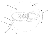
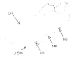
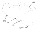
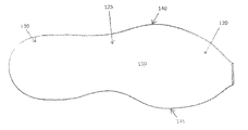
図2A〜図2Dに、上に構造的特徴が作成された例示的な靴100を示す。靴100は、アッパー105を含み、アッパー105はその下部分115に取り付けられた底110を有する。靴100は、足前部領域120と、足中央部領域125と、ヒール領域130と、足を受け入れることができる開口部135と、を含む。靴100は、側面140と内側面145とを更に含む。底110はミッドソール150を含み、ミッドソール150は、靴100の内部に面する上面210と靴100が地面に接しているときに地面に面する下面155とを有する。一実施形態においては、ミッドソール150は、EVA、及び例えば、グランドコンタクトEVAなどであるが、これらに限定されない、靴底110の接地面として使用することを可能にする適切な性能、牽引力、摩耗及び耐久特性を有する材料から形成してもよい。別の実施形態においては、1つ以上のアウトソール要素(例えば、ゴムアウトソール要素)を下面155に取り付け、靴100に適切な接地特性を付与してもよい。
2A-2D show an
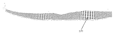
ミッドソール150は、ミッドソール150の周縁部に延在する側壁160を更に含む。いくつかの実施形態及び変形形態では、幾何学的構造的特徴及び/又は装飾的デザインがレーザマーキング及び/又はエングレービングによって側壁160及び/又はアウトソールに組み込まれ、側壁160及びミッドソール150の種々の領域に特定の構造的特性、性能特性及び審美的特性を付与する。これら幾何学的特徴は、例えば、1つ以上の構造的要素(例えば、空洞、溝若しくはその他の穴、例えば、側壁160内へと延びる凹状要素165、及び/又は1つ以上の上昇構造、例えば、側壁160から外に延びる凸状要素170。凸状要素170は、表面の一部分の周りの材料を除去し、それにより表面上に上昇要素を残すことによって形成してもよい)を含んでもよい。構造的要素は任意の数及び配置のものであってもよいとともに、任意の適切な形状、大きさ、向き及び深さのものであってもよく、更に、必要な又は所望の特定の構造特性、性能特性及び審美的特性に応じて任意の適切な状態で配置されてもよい。例えば、凹状要素165及び凸状要素170は、側壁160内へと又は側壁160から外へと延びる離散的楕円体の一部分(例えば、扁球、長球若しくは球状体の一部分)、又は離散的多面体要素の一部分として形成してもよい。例示的な多面体要素は、四面体(すなわち、4つの三角形面を有する多面体)、立方体、八面体、十二面体、二十面体等などであるが、これらに限定されない多面体形状、及び例えば、三角形、四角形、矩形、五角形、六角形又はより高次の断面を有する3次元形状を含んでもよい。要素は規則的若しくは不規則な形状であってもよい及び/又は対称若しくは非対称であってもよい。
種々の実施形態において、構造的要素は物体の表面(例えば、靴底)から任意の適切な程度内側及び外側に延出してもよいとともに(すなわち、構造的要素は任意の適切な厚さ/深さを有してもよい)、構造的要素の側壁は任意の鋭角(例えば、約5°〜約90°、若しくは10°〜80°、若しくは20°〜70°)若しくは鈍角(例えば、約90°〜約135°)で延びてもよい、又は側壁160の周辺表面に垂直に若しくは実質的に垂直に延びてもよい。いくつかの実装形態においては、構造的要素の断面形状は各要素の厚さ/深さにわたって実質的に一定のままであってもよい。他の実装形態においては、断面形状は要素の厚さ/深さにわたって変化してもよい(各要素の厚さ/深さにわたって断面の面積が変化することに加えて又はその代わりに)。構造的要素の厚さ/深さは靴壁の範囲にわたって一定であっても変化してもよい。
In various embodiments, the structural element may extend in and out to any suitable extent from the surface of the object (eg, the sole) (ie, the structural element may have any suitable thickness / depth). The sidewalls of the structural element can have any acute angle (eg, about 5 ° to about 90 °, or 10 ° to 80 °, or 20 ° to 70 °) or obtuse angle (eg, about 90 ° (° to about 135 °), or may extend perpendicular or substantially perpendicular to the peripheral surface of the
いくつかの実施形態では、側壁160に1つ以上の凹状要素165を配置することで、側壁160のその部分の材料の量を低減し、それによって、その側壁160の部分における材料の密度を低下させることによりその部分における側壁160の剛性を低下させることができる。したがって、このことにより、側壁160のその部分の圧縮性を増加させることができ、したがって、より高い又は柔らかい緩衝性を持つ局所的領域をその領域に設ける。凹状要素165が凹状要素165の位置に近接するミッドソール150の緩衝性を変化させることができる程度は、側壁160領域内における凹状要素165の大きさ、厚さ/深さ、形状、向き及び/又は分布などであるが、これらに限定されない要因次第であってもよい。加えて、外側スキン層の構造特性(例えば、スキン層の厚さ、層の剛性、及び/又はミッドソール150の内部発泡体に対するスキン層の剛性の差)などであるがこれに限定されないミッドソール150に使用される材料の特性は、要素165に近接するミッドソール150の緩衝特性を凹状要素165が変化させる程度に影響する場合がある。一実施形態においては、凹状要素165の厚さ/深さを増加させる(すなわち、凹状要素165が延びるミッドソール150内への距離を増加させる)と、凹状要素165の周りにおけるミッドソールの剛性が低下し、これによって、ミッドソール150をその領域において事実上より柔らかくする。
In some embodiments, placing one or more
同様に、側壁160の一部分における1つ以上の凸状要素170の大きさ、厚さ/深さ、形状、向き及び/又は分布が凸状要素170に近接するミッドソール150の緩衝特性に影響する可能性がある。例えば、側壁160上の凸状要素170は、底の圧縮及び/又は撓みに対し付加的な抵抗を付与することができ、したがって、凸状要素170が付加された領域における側壁160(及び側壁160のその部分に近接するミッドソール150)の構造特性に影響し得る。
Similarly, the size, thickness / depth, shape, orientation, and / or distribution of one or more
このようにして形成してもよい他の構造的特徴としては、溝(例えば、フレックス溝)、穴、空洞、スロット、トラクション要素及び/又は任意の他の適切な離散的若しくは結合した表面構造が挙げられる。例えば、任意の適切な大きさ、形状及び又は向きのフレックス溝を靴のミッドソールの表面に形成し、ミッドソールのその領域に適切な可撓性を付与してもよい。種々の実施形態においては、エングレービングされた要素の大きさ、形状、向き、深さ及び他の構造的特徴(並びに/又はマーキングされた要素の大きさ、形状及び向き)は処理される表面の領域にわたって変化する又は一定のままである、のいずれかであってもよい。一実施形態においては、本明細書中に記載される方法及びシステムを使用し、一定の若しくは変化する幾何学的パターン、文字及び/若しくは数、並びに/又はトレードマーク、スポーツチームを識別する印、マップ、顔等などであるがこれらに限定されない審美的デザイン及びイメージを含むがこれらに限定されない任意の適切なマーキング又はエングレービングされた形状を作成してもよい。より具体的には、本明細書中に記載される方法及びシステムの実施形態は、パワー、時間、角度及びエングレービング用レーザビーム(又はビーム)から物体の表面までの距離などの要素の変化を慎重に制御しながら、物体の表面への多様で複雑な3次元造形特徴のエングレービングを可能にし、非常に複雑且つ細密な3次元表面を有するエングレービングされた表面特徴の作成を可能にする。 Other structural features that may be formed in this way include grooves (eg, flex grooves), holes, cavities, slots, traction elements and / or any other suitable discrete or combined surface structure. Can be mentioned. For example, flex grooves of any suitable size, shape and / or orientation may be formed on the surface of the shoe midsole to impart appropriate flexibility to that region of the midsole. In various embodiments, the size, shape, orientation, depth and other structural characteristics of engraved elements (and / or the size, shape and orientation of marked elements) are treated surfaces. May vary or remain constant over a range of. In one embodiment, using the methods and systems described herein, constant or changing geometric patterns, letters and / or numbers, and / or trademarks, indicia identifying sports teams, Any suitable marking or engraved shape may be created including, but not limited to, aesthetic designs and images, such as but not limited to maps, faces, etc. More specifically, embodiments of the methods and systems described herein may vary in factors such as power, time, angle, and distance from the engraving laser beam (or beam) to the surface of the object. Enables the creation of engraved surface features with very complex and detailed 3D surfaces, enabling the engraving of various complex 3D features on the surface of the object while carefully controlling To.
いくつかの実施形態では、審美的要素及び/又は構造的要素の組み込みに加えて、レーザを用いて、靴の表面(及び例えば、側壁160及び/又はアウトソール)の質感表現を加えてもよい。質感表現(すなわち、審美的目的のため、浅い表面パターン又は粗さを壁の表面に付加するもの)を、側壁160の領域に、構造的要素の周りに若しくは構造的要素から離して加えてもよく、又は周囲側壁160に加えて若しくは周囲側壁160の代わりに、構造的要素の表面にわたって加えてもよい。質感表現から生じる浅い表面パターン及び/又は表面粗さのすべて又は一部もまた、審美性を更に高めるために着色(例えば、塗装)してもよい。
In some embodiments, in addition to incorporating aesthetic and / or structural elements, a laser may be used to add a textured representation of the shoe surface (and, for example,
靴底110の一部分の例証的な構造的特徴及び/又は装飾的デザインを図3A〜図3Mに示す。当業者であれば、図3A〜図3Mに示す構造的特徴及び装飾的デザインは、限定のためではなく説明のために示されることは理解することができる。 Illustrative structural features and / or decorative designs for a portion of the sole 110 are shown in FIGS. 3A-3M. One skilled in the art can appreciate that the structural features and decorative designs shown in FIGS. 3A-3M are shown for illustration rather than limitation.
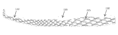
例えば、図3Aは、側壁160を有するミッドソール150を示す。側壁160は、ヒール領域130の小さな浅い穴200が足前部領域120では大きく深い穴202に移行している、様々な穴の大きさ、深さ及び密度を持つくぼみ又は穴のパターンを組み込む。別の実施形態において、穴は任意の適切な一定の若しくは異なる大きさ、深さ、形状及び/又は密度のものであってもよく、パターンは任意の適切な状態でランダム化されていても組織化されていてもよい。側壁160の異なる領域の穴の大きさ、深さ及び/又は密度を変えることは、一実施形態では、穴に近接するミッドソール150の可撓性及び/又は緩衝特性を変化させるにあたり有利であってもよく、より大きな、より深い及び/又はより接近して配置された穴はその領域におけるミッドソール150の密度を低下し、したがって、ミッドソール150をその領域においてより柔らかく且つより圧縮可能にする。
For example, FIG. 3A shows a
図3Bは、側壁160を有するミッドソール150を示す。側壁160は、ヒール領域130におけるより大きな、より低密度の山形205が足前部領域120ではより小さな、より高密度の山形205に移行している、異なる大きさ、深さ及び/又は密度を持つ一連の山形特徴205を組み込む。同じく、山形205の大きさ、深さ及び密度は山形205に近接するミッドソール150の可撓性及び/又は緩衝性を変化させることができる。加えて、山形205の向きは、一実施形態において、1つ以上の特定方向におけるミッドソール150の圧縮を優先的に支持してもよく、山形205は、例えば、着地イベント時に靴が地面に最初に接触する(第1の角度で)際にはミッドソール150のより大きな圧縮(又は緩衝)を支持し、着地イベントのつま先が離れる部分(第2の異なる角度で)の最中には、より少ない圧縮、したがって、アスリートが踏み切ることができるより剛性の高い表面を提供する方向に向けられる。
FIG. 3B shows a
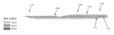
穴、くぼみ、フレックス溝又は他の表面特徴は、靴底110(若しくはその一部分)にわたって均一な(若しくは実質的に均一な)深さのものであってもよく、又は靴底110の異なる領域間において深さが変化してもよい。深さの変化は、必要とされる特定の構造的及び/又は審美的効果に応じて急激若しくは漸進的のいずれであってもよい。例えば、図3Cは、実質的に均一な深さ(この場合、約5mm)の穴208の組織化されたパターンを示し、図3Dは、穴208の深さが、ミッドソール160の長さにわたって約1mm(側壁160の外側領域210)と、約3mm(側壁160の中間領域215)と、約5mm(側壁160の中心領域220)との間で変化する穴パターンを示す。種々の実施形態において、靴の壁にエングレービングされた特徴の深さは、0mmから25mmまでの範囲又はこれを超えてもよい。一実施形態においては、特徴は、物体(例えばミッドソール)内を1つの表面から別の表面まで(例えば、通風目的又は付加的な構造の取り付けを可能にするため)完全に貫通するチャネルであってもよい。
The holes, indentations, flex grooves or other surface features may be of a uniform (or substantially uniform) depth across the sole 110 (or a portion thereof) or between different regions of the sole 110 The depth may vary at. The change in depth can be either abrupt or gradual depending on the particular structural and / or aesthetic effect required. For example, FIG. 3C shows an organized pattern of holes 208 with a substantially uniform depth (in this case about 5 mm), and FIG. 3D shows that the depth of the holes 208 extends over the length of the
構造的特徴は靴底110の全長にわたって又はその一部分のみにわたって延在してもよい。このことは、例えば、(エングレービングされた特徴に近接する)靴底110の特定の領域内のより低密度の、したがって、より緩衝性のある底部分と、エングレービングされた壁領域のない領域に近接するより高密度の、したがって、より硬い底部分と、の提供において有利であってもよい。例えば、ヒール領域130にはエングレービングされた壁部分を有し、足前部領域120にはエングレービングされた領域を有しない単一の一体材料のミッドソール150を有する靴を作成することで、ヒール領域130において増加した緩衝性(足の着地時に有利であり得る)と、より硬い足前部領域120(つま先が離れる際に性能の利点を提供することができる)とを有するミッドソール150を作成する。加えて、本明細書中に記載されるシステム及び方法は、高い可撓性が要求される領域においてより深いフレックス溝及び/又はより多数のフレックス溝の提供を可能にする一方で、より低い可撓性を必要とする領域はより少数の及び/若しくはより浅いフレックス溝を有することができる、又は更にはフレックス溝を有し得ない。
The structural features may extend over the entire length of the sole 110 or only over a portion thereof. This may be the case, for example, of the lower density and therefore more buffered bottom portion within a particular area of the sole 110 (close to the engraved features) and the engraved wall area. It may be advantageous in providing a denser and therefore harder bottom portion proximate to no area. For example, creating a shoe with a single,
特定の実施形態では、このような構造的特徴は靴の限定部分に制限することができる。例えば、靴の種々の実施形態は、エングレービングされた特徴を、内側面又は側面(又は側面と内側面とに異なるエングレービングされた特徴を有する)にのみ含み得る、並びに/又はエングレービングされた構造的特徴を足前部、足中央部及び/若しくはヒール領域(若しくはその一部分)にのみ有し得る。例えば、安定性及び回内制御用の靴は、より硬い内側面(少なくとも足中央部領域において)と、より柔らかい、より緩衝性のある側面(多くの場合、ヒール領域及び足中央部領域において)と、を必要とすることが多い。本明細書中に記載される方法及びシステムは、これら領域における足中央部の緩衝性を靴の内側面に対して増すため、側方ヒール領域と側方足中央部領域とにエングレービングされた部分を有する単一材料のミッドソールの作成を可能にする。 In certain embodiments, such structural features can be limited to limited portions of the shoe. For example, various embodiments of a shoe may include engraved features only on the inner surface or side surface (or have different engraved features on the side surface and the inner surface), and / or Binged structural features may only be present at the front, midfoot and / or heel regions (or portions thereof). For example, shoes for stability and pronation control have a stiffer inner surface (at least in the midfoot area) and a softer, more shocking side (often in the heel and midfoot areas). And often require. The methods and systems described herein are engraved into the side heel region and the side foot central region to increase the midfoot foot cushioning in these regions relative to the inner surface of the shoe. This makes it possible to create a single material midsole with a curved portion.
本明細書中に記載される方法及びシステムは、任意の適切な形状及び配置を有する複雑な幾何学的構造の壁特徴を作成するための手段を提供する。ヒール領域130におけるより大きな、より低密度の特徴が、足前部領域120においてより小さな、より高密度の特徴に移行する、異なる大きさ及び密度を持つ一連の様式化された三角形のくぼんだ特徴220を含む側壁160を有する例示的なミッドソール150が図3E(くぼんだ特徴220はミッドソール150のほぼ全長に延在している)に示されている一方、異なる大きさ及び均一な深さを持つ一連の様式化された三角形の上昇した特徴225を含む側壁160を有するミッドソール150が図3Fに示されており、この実施形態では、特徴225はヒール領域130に限定されている。
The methods and systems described herein provide a means for creating wall features of complex geometric structures having any suitable shape and arrangement. A series of stylized triangular recessed features with different sizes and densities, where larger, lower density features in the
図3Gは、側壁160を有するミッドソール150を示す。側壁160は、異なる大きさ及び形状のグリッド255を含むパターンを含み、グリッド255は、各グリッドスクエアに異なる大きさの円形又は実質的に円形の特徴230を有し、より小さな、より高密度のグリッド及び円形の特徴230を足中央部領域125及び後部ヒール領域235及びつま先領域240に有するとともに、より大きな、より低密度のグリッド及び円形の特徴230を足の中足骨頭に近接する領域245内と、足の踵球に近接する領域250内とに有する。
FIG. 3G shows a
図3Hは、側壁160を有するミッドソール150を示す。側壁160は、異なる大きさ及び形状の溝(及び例えば、可撓性を高める溝又はフレックス溝)のグリッド255を含むパターンを含み、グリッド255は、複数の実質的に垂直な溝260と、複数の実質的に長手方向に延在する溝265と、を含む。種々の実施形態では、溝260、265は互いに対して及び靴の長手方向の軸線に対して任意の適切な角度で配向されてもよい。
FIG. 3H shows a
図3Iは、側壁160を有するミッドソール150を示す。側壁160は、靴底110の実質的に全長にわたって延在する異なる大きさの円形の又は実質的に円形の特徴270を含むパターンを含む。
FIG. 3I shows a
一実施形態においては、本明細書中に記載されるシステム及び方法を使用して、側壁160と靴底110(又はその1つ以上の部分)の接地する下面155との両方にわたって延在するパターンを有する靴底を作成することができる。これは、パターンが複数の材料にわたって延在し、例えば、パターンがEVAミッドソール150の表面とゴムアウトソール280の表面とにわたって延在することを要してもよい。図3J及び図3Kは、例えば、側壁160と接地する下面155との両方にわたって延在する多角形285(表面に溝287をエングレービングすることによって形成された)のランダム化パターンを有する靴底110を示す。更なる実施形態では、エングレービングされた及び/又はマーキングされたパターンが靴の任意の部分にわたって、及び例えば、靴のアッパー及び底部分の少なくとも一部分にわたって延在し得る。
In one embodiment, a pattern that extends over both the
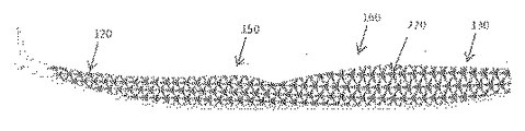
図3Lは、側壁160を有するミッドソール150を示す。側壁160は、ミッドソール150の中間足中央部領域125にわたって延在する一連のX字形の空洞を含むパターンを含む。空洞は大きさ及び密度が異なり、より大きな、より高密度の空洞295はエングレービングされた領域の中心部分290にあり、より小さな、より低密度のX字形の空洞297はエングレービングされた領域の縁端へと移行している。一実施形態においては、更なる審美的及び/又は構造的利点を付与するために、空洞(又は空洞のいくつか)に、材料が充填されてもよい又は材料が少なくとも部分的に充填されてもよい。例えば、空洞295に、周囲のミッドソール150の密度よりも高い密度を有する材料を充填することができ、これにより、密度を増加した領域を提供し、靴のミッドソール150に安定性領域を提供する。加えて又はあるいは、ミッドソール150に固有の視覚態様を付与するために、充填材料はミッドソール150の色と対照的な色を有してもよい。一実施形態においては、充填材料は蛍光材料(例えば、フォトルミネセンス材料)を含み得る。充填材料は空洞295内に固体として挿入してもよく、又は空洞295に、後にそこで固化する液体若しくはゲルとして適用してもよい。一実施形態においては、充填材料は塗料を含んでもよい又は塗料のみから実質的になってもよい。
FIG. 3L shows a
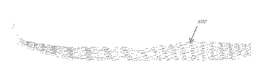
図3Mは、側壁160を有するミッドソール150を示す。側壁160は、異なる大きさ及び密度を持つ一連のエングレービングされた鋸歯波状特徴300を含み、足中央部領域125のより大きな、より低密度の波状特徴は足前部領域120においてかなり小さな、より高密度の波状特徴に移行しており、ヒール領域130においてはわずかに小さな、より高密度の波状特徴に移行している。
FIG. 3M shows a
図3A〜図3Mに示すパターンは、靴のミッドソール及びアウトソールの種々の部分に配置されており、種々の構成にあるエングレービングされた構造的特徴の例である。別の実施形態においては、ミッドソールの特定の性能特性及び審美的要件に応じて構造壁特徴の任意の適切な配置を作成してもよい。エングレービングされた構造的特徴に加えて、本明細書中に記載される方法及びシステムを用いて、図3A〜図3Mに示すパターン又は任意の他の適切な審美的デザインを有する審美的表面マーキングを作成することができる。 The patterns shown in FIGS. 3A-3M are examples of engraved structural features that are located on various portions of the shoe midsole and outsole and are in various configurations. In other embodiments, any suitable arrangement of structural wall features may be created depending on the specific performance characteristics and aesthetic requirements of the midsole. In addition to the engraved structural features, an aesthetic surface having the pattern shown in FIGS. 3A-3M or any other suitable aesthetic design using the methods and systems described herein. Marking can be created.
本発明の一態様は、このようにして作成したエングレービングされた壁部分に1つ以上の色を適用することにより、靴の壁に固有の審美的デザインを作成するための方法及びシステムを含む。これは、例えば、底(若しくはその一部分)を全体的に又は実質的に第1の色を有する材料から形成し、その後、エングレービングされた特徴に第2の、対照的な色を選択的に付加し、構造の差を示す視覚効果を靴底の領域にわたって作成することによって実現してもよい。一実施形態においては、3つ以上の色を使用してより複雑なシェーディング及び着色を作成してもよい。 One aspect of the present invention provides a method and system for creating an aesthetic design unique to a shoe wall by applying one or more colors to the engraved wall portion thus created. Including. This may, for example, form the bottom (or a portion thereof) entirely or substantially from a material having a first color, and then selectively select a second, contrasting color for the engraved features. In addition, the visual effect indicating the difference in structure may be created over the region of the shoe sole. In one embodiment, more than two colors may be used to create more complex shading and coloring.
一実施形態においては、色は、物体(例えば、靴のミッドソール)の表面を1つ以上の対照的な色で塗装する又はそれ以外で着色し、その後、表面にレーザエングレービングし、対照的な色の外部塗装済み壁と、下にある色のエングレービングされたパターンと、を残すことによって適用される。別の実施形態では、エングレービングされた構造的要素の表面のいくつかの部分のみが第2の色で被覆される一方で、残りの表面部分は第1の、下にある色を維持するように、エングレービングされた構造的特徴を有する表面上に、第2の、対照的な色を、表面に対し非垂直角度で噴霧してもよい。 In one embodiment, the color is applied by painting or otherwise coloring the surface of an object (eg, a shoe midsole) with one or more contrasting colors, and then laser engraving the surface to control Applied by leaving an external painted wall of a typical color and an engraved pattern of the underlying color. In another embodiment, only some portions of the surface of the engraved structural element are coated with the second color, while the remaining surface portions retain the first, underlying color. Thus, a second, contrasting color may be sprayed at a non-perpendicular angle with respect to the surface on the surface with engraved structural features.
別の実施形態では、マスキング要素の適用及び除去により、複数色の表面を形成してもよい。より具体的には、マスキング要素はエングレービング前に(及びいくつかの実施形態では、表面に第1の塗料を塗布後)表面に適用してもよい。レーザを、その後、マスクされた表面上に誘導し、マスクされた表面の部分及びその下の壁をエングレービング除去し、これにより、未露光の領域(マスキング要素によって被覆された)と造形領域(マスキング要素によって被覆されていない)とを含む造形表面を作成する。別の実施形態では、レーザは、目標位置において物体自体の壁をエングレービングすることなくマスキング材料のみを除去するように適合されてもよい。 In another embodiment, multiple color surfaces may be formed by applying and removing masking elements. More specifically, the masking element may be applied to the surface before engraving (and in some embodiments, after applying the first paint to the surface). The laser is then directed onto the masked surface, engraving away portions of the masked surface and the underlying walls, thereby unexposed areas (covered by masking elements) and build areas A shaped surface is created that includes (not covered by a masking element). In another embodiment, the laser may be adapted to remove only the masking material without engraving the wall of the object itself at the target location.
表面にパターンをエングレービングした後、造形表面(より具体的には、マスクされ、エングレービングされていない表面部分と、エングレービングされた、造形表面部分との両方)に塗料又は他の着色剤を塗布することができ、塗料はエングレービングされた壁領域に接着するとともにそれをコーティングするが、マスキング要素によって被覆された表面領域には接着もコーティングもされない。その後、マスキング要素を除去し、第1の色を有するエングレービングしていない部分と、塗料によってコーティングされ、したがって、第2の色を有するエングレービング済み部分と、を有する壁表面を残すことができる。塗料は、噴霧、塗装、ディップコーティング又は任意の他の適切なコーティング法によって塗布してもよい。一実施形態においては、異なる色の塗料が表面の異なる領域に塗布され、したがって、複数色のエングレービングされたパターンをその上に有する物体を作成する。 After engraving the pattern on the surface, paint or other on the build surface (more specifically, both the masked, non-engraved surface portion and the engraved, build surface portion) Colorant can be applied and the paint adheres to and coats the engraved wall area, but does not adhere or coat the surface area covered by the masking element. Thereafter, the masking element is removed, leaving a wall surface having an unengraved part having a first color and an engraved part coated with a paint and thus having a second color. Can do. The paint may be applied by spraying, painting, dip coating or any other suitable coating method. In one embodiment, different colored paints are applied to different areas of the surface, thus creating an object having a multi-colored engraved pattern thereon.
一実施形態においては、レーザによる物体の表面及び/又はマスキング要素の焼傷若しくは他の損傷を防ぐために、レーザエングレービングプロセスの前、最中及び/又は直後に、マスキング要素(及び物体の表面の任意の露出部分)に流体を塗布してもよい。より具体的には、流体は、エングレービング中及びエングレービング後の、壁材料及び/又マスキング材料の不要な焼傷及び/若しくは変色を防ぐための冷却剤として機能してもよい。流体は、噴霧、塗装、ディップコーティング又は任意の他の適切なコーティング法により塗布してもよい。一実施形態においては、流体は表面上にブラシで塗布され、表面上における流体の実質的に均一なコーティングを確実とする。 In one embodiment, the masking element (and the surface of the object) before, during and / or immediately after the laser engraving process to prevent burns or other damage to the object surface and / or masking element by the laser. The fluid may be applied to any exposed portion of (1). More specifically, the fluid may function as a coolant to prevent unwanted burns and / or discoloration of the wall material and / or masking material during and after engraving. The fluid may be applied by spraying, painting, dip coating or any other suitable coating method. In one embodiment, the fluid is applied with a brush on the surface to ensure a substantially uniform coating of the fluid on the surface.
マスキング要素は、接着剤又は他の適切な接着方法(例えば、静電気、真空等)の使用により表面に取り外し可能に付着させた材料シート(例えば、接着剤マスキングテープ、プラスチックフィルム、テキスタイルシート等)を含んでもよい又はこの材料シートのみから実質的になってもよい。あるいは、マスキング要素は、表面に塗布されるとともに、エングレービング後に除去することができる(例えば、洗い流される)マスキング液若しくはゲル(例えば、低接着塗料、離型液、ゴムのり等)を含んでもよい又はそれらのみから実質的になってもよい。マスキング液は噴霧、塗装、ディップコーティング又は任意の他の適切なコーティング法により塗布してもよい。 The masking element is a sheet of material (eg, adhesive masking tape, plastic film, textile sheet, etc.) that is removably attached to the surface by use of an adhesive or other suitable bonding method (eg, static electricity, vacuum, etc.). It may comprise or consist essentially of this material sheet alone. Alternatively, the masking element may include a masking solution or gel (eg, low adhesion paint, mold release fluid, rubber paste, etc.) that is applied to the surface and can be removed (eg, washed away) after engraving. Or may consist essentially only of them. The masking liquid may be applied by spraying, painting, dip coating or any other suitable coating method.
物体(例えば、靴のミッドソール側壁、アウトソール表面等)の表面に装飾的デザイン及び/又は構造的特徴を作成する例示的な方法を、図4のフローチャートに示す。当該方法は、処理される物体の表面にマスキング媒体を塗布するステップ(ステップ1)と、マスキング媒体を通して物体の表面を既定のパターンに(例えば、レーザを使用して)エングレービングするステップ(ステップ2)と、エングレービングプロセス中、エングレービング済み表面に既定の間隔で流体(例えば、石鹸溶液)を塗布するステップ(ステップ3A)と、流体を有する表面にブラッシングするステップ(ステップ3B)と、エングレービングするステップ(ステップ2)を繰り返すステップと、流体を塗布するステップ(ステップ3A)と、表面内において1つ以上の既定の深さを有する既定のパターンに達する(ステップ4)までブラッシングする(ステップ3B)操作と、を含む。 An exemplary method for creating a decorative design and / or structural feature on the surface of an object (eg, a shoe midsole sidewall, outsole surface, etc.) is shown in the flowchart of FIG. The method includes applying a masking medium to the surface of the object to be processed (step 1) and engraving the surface of the object through the masking medium into a predetermined pattern (eg, using a laser) (step). 2) applying a fluid (eg, a soap solution) to the engraved surface at predetermined intervals during the engraving process (step 3A) and brushing the surface with the fluid (step 3B) Repeat the steps of engraving (step 2), applying fluid (step 3A), and brushing until a predetermined pattern having one or more predetermined depths in the surface is reached (step 4) (Step 3B).
例えば、第1のステップにおいて、マスキング媒体を、マスキング媒体中にしわも隙間もないことを確実にして、物体の表面(例えば、ミッドソールの側壁)に塗布してもよい。いくつかの実装形態においては、マスキング材料は、エングレービングプロセスを容易にするために予め印刷されたパターンを含んでもよい(例えば、エングレービング時にレーザが追従するパターンを提供することによって)。あるいは、パターン画像をマスキング媒体上に投影してもよい。自動化実装形態では、レーザは多軸位置決めデバイスとともに使用してもよい。多軸位置決めデバイスは、適切な制御部によって、側壁内に所望のへこみ及び空洞を作成するためのパターン(例えば、データストレージ媒体に保存されている)を生成するように制御され、へこみ及び空洞の位置、大きさ、形状及び深さはレーザと位置決めデバイスとによって厳密に制御されてもよい。 For example, in the first step, the masking medium may be applied to the surface of the object (eg, the side wall of the midsole) ensuring that there are no wrinkles or gaps in the masking medium. In some implementations, the masking material may include a pre-printed pattern to facilitate the engraving process (eg, by providing a pattern that the laser follows during engraving). Alternatively, the pattern image may be projected on the masking medium. In an automated implementation, the laser may be used with a multi-axis positioning device. The multi-axis positioning device is controlled by a suitable controller to generate a pattern (eg, stored in a data storage medium) to create the desired dent and cavity in the sidewall, and the dent and cavity The position, size, shape and depth may be strictly controlled by the laser and positioning device.
発光デバイスのビーム(例えば、CO2レーザ)は、その後、ミッドソールの側壁上の別々の区域及び領域に誘導され、マスキング材料を切断するとともに、ミッドソールの側壁のパターン及び既定の深さにしたがって、ミッドソール材料を選択的にエングレービング(ステップ2)してもよい。有利には、エングレービングされないミッドソールの側壁の区域及び領域は、マスキング材料によってマスクされた(すなわち被覆された)ままであり、これにより、これら区域及び領域を、任意の後に塗布される塗料から保護する。 The light emitting device beam (eg, a CO 2 laser) is then directed to separate areas and regions on the sidewalls of the midsole, cutting the masking material and in accordance with the pattern and predetermined depth of the sidewalls of the midsole. The midsole material may be selectively engraved (step 2). Advantageously, the unengraved midsole sidewall areas and regions remain masked (ie, coated) by the masking material so that these areas and regions can be applied to any later applied paint. Protect from.
材料の除去(ステップ2)を、既定の時間(エングレービングされた要素及びエングレービングされる材料の大きさ及び深さに応じてわずか1秒以下から数分であってもよい)にわたり、及び/又はエングレービングされた空洞が壁表面の既定の深さに達するまで(例えば、0.01mm以下から、15mm以下の間、又は更には25mm以上の間)継続してもよい。 Material removal (step 2) for a pre-determined time (which may be as little as 1 second to a few minutes depending on the size and depth of the engraved element and engraved material), And / or may continue until the engraved cavity reaches a predetermined depth of the wall surface (eg, between 0.01 mm or less, 15 mm or less, or even 25 mm or more).
一実施形態においては、エングレービングプロセス全体における1つ以上の間隔において、マスキング要素と物体表面とを冷却する及び/又はそうでなければ保護するために、並びにレーザエングレービングプロセスによって生成された任意の廃棄物を除去するために、表面を処理してもよい。一実施形態においては、(例えば、液体の塗布により)レーザ処理中にマスキング要素と物体表面とを冷却及び保護することもまた、表面からデブリを清掃するための手段を有利に提供してもよい。別の実施形態においては、冷却/保護ステップは清掃ステップから分離することができる。 In one embodiment, generated at one or more intervals throughout the engraving process to cool and / or otherwise protect the masking element and the object surface, and by the laser engraving process. The surface may be treated to remove any waste. In one embodiment, cooling and protecting the masking element and the object surface during laser processing (eg, by application of a liquid) may also advantageously provide a means for cleaning debris from the surface. . In another embodiment, the cooling / protection step can be separated from the cleaning step.
清掃ステップは、洗出(例えば、圧縮空気による)、洗浄、ブラッシング及び/若しくはふき取り(例えば、布による)を含んでもよい又はこれらのみから実質的になってもよい。例えば、流体(例えば、水などの洗浄剤)を、エングレービング済みの区域及び領域に、表面が液体で薄く被覆されるまで塗布してもよく(ステップ3A)、その後、濡れた区域を(例えば、布又はブラシを使用して)優しく拭き取って清掃し、壁表面又はマスキング材料を損傷することなくデブリを除去する(ステップ3B)。洗浄後、(例えば、圧縮空気による)洗出又は任意の他の適切な方法によって任意の過剰な液体を除去してもよい。いくつかの実装形態においては、洗浄剤は、例えば、物体の表面上における液体の均一な分散を確実にするのを助けることができる界面活性剤(例えばセッケン)を含む水溶液である。洗浄/清掃剤は、例えば、水とセッケンとを含む水溶液であってもよく、セッケンの割合は、約0.1%〜約50%の範囲であり、一実施形態においては、約0.5%〜約5%であり、例えば、約1%である。 The cleaning step may include washing (eg, with compressed air), washing, brushing and / or wiping (eg, with a cloth) or may consist essentially of these. For example, a fluid (eg, a cleaning agent such as water) may be applied to the engraved areas and regions until the surface is thinly coated with liquid (step 3A), after which the wet areas are ( Gently wipe and clean (eg, using a cloth or brush) to remove debris without damaging the wall surface or masking material (step 3B). After washing, any excess liquid may be removed by washing (eg, with compressed air) or any other suitable method. In some implementations, the cleaning agent is, for example, an aqueous solution that includes a surfactant (eg, soap) that can help ensure a uniform dispersion of the liquid on the surface of the object. The cleaning / cleaning agent may be, for example, an aqueous solution comprising water and soap, with the soap percentage ranging from about 0.1% to about 50%, and in one embodiment about 0.5%. % To about 5%, for example, about 1%.
後に続くアブレーション/材料除去(ステップ2)及び流体塗布(ステップ3A)及びブラッシング(ステップ3B)は、所望の最終深さ及びパターンに達するまで、対応する既定の時間及び/又は既定の深さ継続される。したがって、プロセスは、いくつかの「パス」を含んでもよい。有利には、側壁の表面上と、前のパス中に作成された凹状開口部又はソケット内とに洗浄剤が吸着された状態で、それぞれの後のパスにおいて、アブレーション/材料除去(ステップ2)が実施される。その結果、洗浄剤は更に、アブレーションゾーンに近接するミッドソールの複合材料をレーザによって生成される熱から保護する。 Subsequent ablation / material removal (step 2) and fluid application (step 3A) and brushing (step 3B) are continued for a corresponding predetermined time and / or predetermined depth until the desired final depth and pattern are reached. The Thus, the process may include several “passes”. Advantageously, in each subsequent pass, ablation / material removal (step 2) with the cleaning agent adsorbed on the surface of the sidewall and in the concave opening or socket created during the previous pass. Is implemented. As a result, the cleaning agent further protects the midsole composite material proximate the ablation zone from the heat generated by the laser.
構造的特徴及び/又は所望の装飾物がミッドソールの側壁に、その必要な深さまで及びその必要なパターンで適用されると、アブレーション/材料除去による、ミッドソールの側壁上の及び側壁内の開口部又はソケットのいずれかの内部の残留物が除去されてもよい(ステップ5)。これは、ふき取り、洗出及び/又は洗浄により実施してもよく、一実施形態においては、液体(例えば、水を含む又は水のみから実質的になる)、及び例えば、液体のジェットを用いたエングレービング済み空洞の洗い流しを伴ってもよい(ステップ5)。材料は、その後、自然乾燥させてもよく(ステップ6)、任意の適切な乾燥法(例えば、熱乾燥、空気乾燥等)により乾燥させてもよい。その後、ミッドソールの側壁の又はミッドソールの側壁上の別々の区域及び領域に着色を選択的に施すことによってミッドソールの審美性を高めてもよい。有利には、一実施形態では、ステップ1〜6によって作成した構造的特徴及び所望の装飾物を着色してもよい(例えば、塗装によって)(ステップ7)一方で、表面の残りの部分はマスクされたままである。 Openings on and in the sidewalls of the midsole by ablation / material removal once structural features and / or desired decorations are applied to the sidewalls of the midsole to its required depth and in the required pattern Residue inside either the part or the socket may be removed (step 5). This may be done by wiping, washing and / or washing, and in one embodiment using a liquid (eg, containing or consisting essentially of water) and, for example, a liquid jet. It may involve flushing the engraved cavity (step 5). The material may then be naturally dried (step 6) or dried by any suitable drying method (eg, heat drying, air drying, etc.). Thereafter, the aesthetics of the midsole may be enhanced by selectively coloring different areas and regions on or on the side wall of the midsole. Advantageously, in one embodiment, the structural features and desired ornaments created by steps 1-6 may be colored (eg, by painting) (step 7) while the rest of the surface is masked It has been done.
例えば、図5を参照すると、構造的特徴及び所望の装飾物は任意の従来の手段によって(例えば、浸漬、噴霧、ブラッシング等により)、1つ以上の色で及び/又は選択的に可変の色密度で塗装されてもよい(ステップ7)。いくつかの実装形態においては、塗装は、浸漬、噴霧、ブラッシング又はそうでなければミッドソールの側壁をプライマーでコーティングすることによって(及び例えば、物体をプライマー溶液中に浸漬して物体の表面のマスクされていない部分にプライマーを施すことによって)ミッドソールの側壁に1つ以上のプライマー剤を施すことにより開始してもよい(例えば、UVベースプライマーを用いて)(図7A)。その後、プライマーを施したミッドソールに熱を加えて(ステップ7B)、乾燥しプライマーを施したミッドソールが硬化する前にプライマーを乾燥させてもよい(ステップ7C)。例えば、プライマーを施したミッドソールは、必要な乾燥時間(例えば、特定のプライマーでは、2分以下から5分以上の間の乾燥時間)にわたり適切な温度で(例えば、特定のプライマーでは、約40℃〜約80℃、又はより具体的には約45℃〜約60℃、及び例えば、約50℃の温度)ミッドソールを加熱することによって乾燥させてもよい(ステップ7B)。プライマーを施し、乾燥させたミッドソールは、その後、照明源(例えば、UVランプなどのUV発光デバイスを用いて)に暴露することによって硬化/活性化させてもよく、(ステップ7C)プライマーを硬化させる。その後、塗料又は別の着色剤を、硬化しプライマーを施したミッドソールに(例えば、浸漬、噴霧、ブラッシング等により)塗布してもよい(ステップ7D)。その後、塗装されたミッドソールに熱を印加し、(ステップ7E)塗料を乾燥させてもよい。例えば、塗装したミッドソールは、使用される特定の塗料並びに特定の加熱温度及び使用するシステムに応じて、任意の適切な時間にわたって加熱してもよく、この時間は、一実施形態においては、約50℃(約122°F)の温度で2〜5分の時間である(ステップ7E)。 For example, referring to FIG. 5, the structural features and desired decorations can be varied in one or more colors and / or selectively variable by any conventional means (eg, by dipping, spraying, brushing, etc.). It may be painted with density (step 7). In some implementations, painting is performed by dipping, spraying, brushing or otherwise coating the sidewalls of the midsole with a primer (and, for example, dipping the object in a primer solution to mask the surface of the object One may start by applying one or more primer agents to the sidewalls of the midsole (by applying a primer to the part that has not been done) (eg, using a UV-based primer) (FIG. 7A). Thereafter, heat may be applied to the primed midsole (step 7B) and the primer may be dried before the primered midsole is cured (step 7C). For example, a primed midsole may be at a suitable temperature (eg, about 40 for a particular primer) over the required drying time (eg, for a particular primer, between 2 minutes and 5 minutes or more). The midsole may be dried (step 7B) by heating the midsole (at a temperature of from about 0C to about 80C, or more specifically from about 45C to about 60C, and for example, about 50C). The primed and dried midsole may then be cured / activated by exposure to an illumination source (eg, using a UV light emitting device such as a UV lamp) (step 7C). Let Thereafter, a paint or another colorant may be applied (eg, by dipping, spraying, brushing, etc.) to the cured and primed midsole (step 7D). Thereafter, heat may be applied to the painted midsole (step 7E) to dry the paint. For example, the painted midsole may be heated for any suitable time, depending on the particular paint used and the particular heating temperature and system used, which in one embodiment is about 2 to 5 minutes at a temperature of 50 ° C. (about 122 ° F.) (step 7E).
ミッドソールの側壁が塗装され(ステップ7D)、塗料が乾燥した(ステップ7E)後、残ったマスキング媒体を除去してもよく(ステップ8)、清浄な外部表面を有するが着色された空洞を有するミッドソールを残し、魅力的且つ望ましい審美的効果を提供してもよい。残留塗料は、その後、着色された空洞から任意の適切な手法で、例えば、ブラッシング、ふき取り及び/又は洗出(例えば、圧縮空気の適用による)によって除去してもよい(ステップ9)。 After the midsole sidewalls are painted (Step 7D) and the paint is dried (Step 7E), the remaining masking media may be removed (Step 8), having a clean exterior surface but colored cavities. The midsole may be left to provide an attractive and desirable aesthetic effect. Residual paint may then be removed from the colored cavities in any suitable manner, such as by brushing, wiping and / or washing (eg, by applying compressed air) (step 9).
別の実施形態においては、上記のステップのすべて又はいくつかの任意の組み合わせを、使用するシステム及び材料の特定の要件並びに所望する特定の結果に応じて使用してもよい。 In other embodiments, any combination of all or some of the above steps may be used depending on the particular requirements of the system and material used and the particular result desired.
いくつかの変形形態において、上述のように、本明細書中に記載される方法は、表面から材料を除去せずに、発光デバイスを用いるミッドソールの側壁の表面の選択的なマーキング/着色において使用してもよい。これはマスキング要素を塗布する必要を有して又は有さず実施してもよい。例えば、一実施形態においては、この着色はマスキング材料を通して行ってもよい(マスキング要素が色マーキングを支持するために使用される場合)。あるいは、マーキングは物体の表面のマスキング要素を全く使用することなく行ってもよい。 In some variations, as described above, the methods described herein can be used in selective marking / coloring of the midsole sidewall surface using a light emitting device without removing material from the surface. May be used. This may be done with or without the need to apply a masking element. For example, in one embodiment, this coloring may be done through a masking material (if a masking element is used to support the color marking). Alternatively, the marking may be performed without using any masking elements on the surface of the object.
審美的パターン及び/又は構造的パターンを物体上に作成するためにレーザマーキング/エングレービングシステムを使用する別の例証的な方法を図6及び図7に示す。この実施形態では、当該方法は、マーキングシステム又はエングレービングシステムのいずれかの選択を可能にするとともに、塗装がある又は塗装がない状態のいずれかにおいてエングレービングを行うことを更に可能にする。エングレービングした物体を塗装する例証的な方法が図7に示される。 Another illustrative method of using a laser marking / engraving system to create an aesthetic pattern and / or a structural pattern on an object is shown in FIGS. In this embodiment, the method allows for the choice of either a marking system or an engraving system and further allows engraving to be performed either in the presence or absence of paint. . An illustrative method for painting an engraved object is shown in FIG.
一実施形態においては、レーザ処理中、物体は大気に開放されている。別の実施形態では、レーザマーキング/エングレービングシステムは、物体を不活性環境内(例えば、窒素、アルゴン又は他の不活性ガスに富んだ環境内)に保持することを可能にする筐体を含む。このことは、レーザ処理中、材料の黄変を低減し、マーキング又はエングレービングプロセスの加工時間を向上させるのに有利であり得る。あるいは、レーザ処理中、(例えば、ガスジェットノズルから)物体又はその一部分に窒素又は別の不活性ガスの流れを適用することができる。 In one embodiment, the object is open to the atmosphere during laser processing. In another embodiment, the laser marking / engraving system includes a housing that allows objects to be held in an inert environment (eg, an environment rich in nitrogen, argon, or other inert gas). Including. This can be advantageous in reducing the yellowing of the material during laser processing and improving the processing time of the marking or engraving process. Alternatively, a flow of nitrogen or another inert gas can be applied to the object or part thereof (e.g., from a gas jet nozzle) during laser processing.
実施形態又は別の実施形態の作成に用いられる材料及び工程段階は、本明細書中に記載される他の実施形態に適用可能であることは理解すべきである。また、本明細書中に記載される実施形態は全般的に靴の構造的特徴及び/又は審美的特徴の作成に関するが、特定の実施形態においては、本明細書中に記載される方法及びシステムは、他の適切な物体にも使用してよいことは理解すべきである。例えば、本明細書中に記載されるシステム及び方法は、衣料(及び例えば、運動用衣料)、又は保護具若しくは保護衣料(例えば、ヘルメット、詰物、肩パッド、アームスリーブ、膝パッド、シンガード等)、ホッケー用スティック、ラクロス用スティック、テニスラケット等などであるが、これらに限定されない運動用具に構造的特徴及び/又は装飾的特徴を付与するために使用してもよい。一実施形態においては、レーザエングレービングは、衣料に(例えば、多層材料の上層に溝をエングレービングすることによって)又はアスリートにより着用される保護用衣料にフレックス溝を加えるために使用され得る。 It should be understood that the materials and process steps used to create one embodiment or another embodiment are applicable to the other embodiments described herein. Also, although the embodiments described herein generally relate to the creation of structural and / or aesthetic features of shoes, in certain embodiments, the methods and systems described herein are described. It should be understood that may be used for other suitable objects. For example, the systems and methods described herein can be used for apparel (and, for example, athletic apparel), or protective gear or protective apparel (eg, helmets, fillings, shoulder pads, arm sleeves, knee pads, shin guards, etc.). , Hockey sticks, lacrosse sticks, tennis rackets, and the like, but may be used to impart structural and / or decorative features to exercise equipment, such as, but not limited to. In one embodiment, laser engraving can be used to add flex grooves to protective apparel worn by clothing (eg, by engraving grooves on top of a multilayer material) or by athletes. .
本発明は、その趣旨又は必須の特徴から逸脱することなく、他の特定形態において具現化してもよい。前述の実施形態は、したがって、あらゆる点において、本明細書中に記載される本発明を限定するよりもむしろ例証するものとみなされる。本発明の範囲は、したがって、前述の明細書よりもむしろ添付の特許請求の範囲によって示され、特許請求の範囲と等価の意味及び範囲内のあらゆる変更は本発明に包含されるものとする。 The present invention may be embodied in other specific forms without departing from its spirit or essential characteristics. The foregoing embodiments are therefore to be considered in all respects illustrative rather than limiting on the invention described herein. The scope of the invention is, therefore, indicated by the appended claims rather than by the foregoing specification, and all modifications within the meaning and scope equivalent to the claims are intended to be embraced therein.
Claims (33)
前記物体の前記表面近傍にレーザを位置決めするステップと、
前記レーザから前記物体の前記表面にレーザビームを誘導し、前記物体の前記表面の少なくとも一部分にマーキングする又はエングレービングするステップと、
前記レーザ及び前記物体の少なくとも1つを移動し、前記物体の前記表面上にパターンを作成するステップであって、前記パターンは、前記物体の前記表面上に審美的特徴及び構造的特徴の少なくとも1つを付与する、ステップと、
を含む、方法。 A method for adding features on the surface of an object,
Positioning a laser near the surface of the object;
Directing a laser beam from the laser to the surface of the object to mark or engrave at least a portion of the surface of the object;
Moving at least one of the laser and the object to create a pattern on the surface of the object, the pattern comprising at least one of aesthetic and structural features on the surface of the object; Grant one step, and
Including the method.
前記マスキング媒体を通して前記物体の前記表面にマーキングする又はエングレービングするステップと、
前記マスキング媒体を除去するステップと、
を更に含む、請求項1に記載の方法。 Applying a masking medium to at least a portion of the surface of the object prior to driving the laser;
Marking or engraving the surface of the object through the masking medium;
Removing the masking medium;
The method of claim 1, further comprising:
前記プライマーを施した物体を乾燥するステップと、
前記プライマーを施した物体を硬化するステップと、
少なくとも1つのエングレービング済み部分に着色剤を塗布するステップと、
前記物体上の前記着色剤を乾燥するために熱を印加するステップと、
を更に含む、請求項13に記載の方法。 Applying a primer to the engraved object;
Drying the primed object;
Curing the primed object;
Applying a colorant to at least one engraved portion;
Applying heat to dry the colorant on the object;
14. The method of claim 13, further comprising:
前記物体のエングレービング中に生じた残留物を洗浄するステップと、
前記物体の前記表面を乾燥するステップと、
を含む、請求項22に記載の方法。 The step of removing the residue is
Cleaning any residue produced during engraving of the object;
Drying the surface of the object;
23. The method of claim 22, comprising:
前記物体の前記表面近傍にUVレーザを位置決めするステップと、
前記レーザから前記物体の前記表面にレーザビームを誘導し、前記物体の前記表面の少なくとも一部分の色を、前記物体の前記表面から材料を除去することなく変化させるステップと、
前記レーザ及び前記物体の少なくとも1つを移動し、前記物体の前記表面上にパターンを作成するステップであって、前記パターンは、前記物体の前記表面上に審美的特徴を付与し、前記物体は、履物物品のアウトソール、ミッドソール、インソール及びアッパーの少なくとも1つを含む、ステップと、
を含む、方法。 A method for creating aesthetic features on the surface of an object, comprising:
Positioning a UV laser near the surface of the object;
Directing a laser beam from the laser to the surface of the object to change the color of at least a portion of the surface of the object without removing material from the surface of the object;
Moving at least one of the laser and the object to create a pattern on the surface of the object, the pattern imparting an aesthetic feature on the surface of the object; Including at least one of an outsole, midsole, insole and upper of the footwear article;
Including the method.
前記物体の前記表面にマスキング媒体を塗布するステップであって、前記物体は、履物物品のアウトソール、ミッドソール、インソール及びアッパーの少なくとも1つを含む、ステップと、
前記物体の前記表面近傍にレーザを位置決めするステップと、
前記レーザから前記物体の前記表面にレーザビームを誘導し、前記物体の前記表面から材料及びマスキング媒体を除去し、前記物体の前記表面の少なくとも一部分に審美的特徴及び構造的特徴の少なくとも1つを付与する、ステップと、
前記マスキング媒体を除去するステップと、
を含む、方法。 A method for imparting aesthetic or structural features on the surface of an object, comprising:
Applying a masking medium to the surface of the object, the object comprising at least one of an outsole, a midsole, an insole and an upper of an article of footwear;
Positioning a laser near the surface of the object;
Directing a laser beam from the laser to the surface of the object, removing material and masking media from the surface of the object, and applying at least one of aesthetic and structural features to at least a portion of the surface of the object; Grant, step, and
Removing the masking medium;
Including the method.
前記物体をプライマー溶液中に浸漬して前記物体の前記表面のマスクされていない部分にプライマーを施すステップと、
前記プライマーを施した物体を乾燥するステップと、
前記プライマーを施した物体を硬化するステップと、
前記物体の前記表面の前記マスクされていない部分の少なくとも一部分に着色剤を塗布するステップと、
前記物体上の前記着色剤を乾燥するステップと、
を含む、請求項27に記載の方法。 Applying at least one color comprises:
Immersing the object in a primer solution and applying a primer to an unmasked portion of the surface of the object;
Drying the primed object;
Curing the primed object;
Applying a colorant to at least a portion of the unmasked portion of the surface of the object;
Drying the colorant on the object;
28. The method of claim 27, comprising:
Priority Applications (2)
| Application Number | Priority Date | Filing Date | Title |
|---|---|---|---|
| JP2022000457A JP7494229B2 (en) | 2014-11-11 | 2022-01-05 | Method for imparting decorative design and structural features to an article of footwear - Patents.com |
| JP2024008637A JP2024028591A (en) | 2014-11-11 | 2024-01-24 | Method of providing decorative designs and structural features on article of footwear |
Applications Claiming Priority (3)
| Application Number | Priority Date | Filing Date | Title |
|---|---|---|---|
| US14/538,343 US9907365B2 (en) | 2014-11-11 | 2014-11-11 | Method of providing decorative designs and structural features on an article of footwear |
| US14/538,343 | 2014-11-11 | ||
| PCT/US2015/060112 WO2016077434A1 (en) | 2014-11-11 | 2015-11-11 | Method of providing decorative designs and structural features on an article of footwear |
Related Child Applications (1)
| Application Number | Title | Priority Date | Filing Date |
|---|---|---|---|
| JP2022000457A Division JP7494229B2 (en) | 2014-11-11 | 2022-01-05 | Method for imparting decorative design and structural features to an article of footwear - Patents.com |
Publications (2)
| Publication Number | Publication Date |
|---|---|
| JP2017533764A true JP2017533764A (en) | 2017-11-16 |
| JP2017533764A5 JP2017533764A5 (en) | 2018-12-20 |
Family
ID=54705832
Family Applications (3)
| Application Number | Title | Priority Date | Filing Date |
|---|---|---|---|
| JP2017524397A Withdrawn JP2017533764A (en) | 2014-11-11 | 2015-11-11 | Method for imparting decorative design and structural features to footwear articles |
| JP2022000457A Active JP7494229B2 (en) | 2014-11-11 | 2022-01-05 | Method for imparting decorative design and structural features to an article of footwear - Patents.com |
| JP2024008637A Pending JP2024028591A (en) | 2014-11-11 | 2024-01-24 | Method of providing decorative designs and structural features on article of footwear |
Family Applications After (2)
| Application Number | Title | Priority Date | Filing Date |
|---|---|---|---|
| JP2022000457A Active JP7494229B2 (en) | 2014-11-11 | 2022-01-05 | Method for imparting decorative design and structural features to an article of footwear - Patents.com |
| JP2024008637A Pending JP2024028591A (en) | 2014-11-11 | 2024-01-24 | Method of providing decorative designs and structural features on article of footwear |
Country Status (6)
| Country | Link |
|---|---|
| US (1) | US9907365B2 (en) |
| EP (1) | EP3217829A1 (en) |
| JP (3) | JP2017533764A (en) |
| KR (2) | KR20240018702A (en) |
| CN (1) | CN107438378B (en) |
| WO (1) | WO2016077434A1 (en) |
Cited By (1)
| Publication number | Priority date | Publication date | Assignee | Title |
|---|---|---|---|---|
| JP2022527566A (en) * | 2018-10-13 | 2022-06-02 | プーマ エス イー | Footwear with degradable ingredients |
Families Citing this family (37)
| Publication number | Priority date | Publication date | Assignee | Title |
|---|---|---|---|---|
| USD953709S1 (en) | 1985-08-29 | 2022-06-07 | Puma SE | Shoe |
| USD855953S1 (en) | 2017-09-14 | 2019-08-13 | Puma SE | Shoe sole element |
| USD911682S1 (en) | 2017-09-14 | 2021-03-02 | Puma SE | Shoe |
| USD910290S1 (en) | 2017-09-14 | 2021-02-16 | Puma SE | Shoe |
| USD911683S1 (en) | 2017-09-14 | 2021-03-02 | Puma SE | Shoe |
| US9861159B2 (en) * | 2015-05-27 | 2018-01-09 | Nike, Inc. | Article of footwear comprising a sole member with apertures |
| US20190184629A1 (en) * | 2015-06-01 | 2019-06-20 | Jkm Technologies, Llc | 3D Printed Footwear Sole with Reinforced Holes for Securing An Upper |
| IT201600089450A1 (en) * | 2016-09-02 | 2018-03-02 | Loft 7 S R L | FOOTWEAR AND PROCEDURE FOR THE TREATMENT OF MATERIALS FOR FOOTWEAR |
| US11117321B2 (en) * | 2016-09-22 | 2021-09-14 | Sciperio, Inc | Selective laser sintered fused deposition printing with cooling |
| USD850766S1 (en) | 2017-01-17 | 2019-06-11 | Puma SE | Shoe sole element |
| CN114983087A (en) * | 2017-02-14 | 2022-09-02 | 爱鞋仕有限公司 | Method and system for producing a foot correction insole, and correction insole or shoe insole |
| EP3589471B1 (en) * | 2017-02-28 | 2023-05-17 | Hewlett-Packard Development Company, L.P. | Radiation amount determination for an intended surface property level |
| CN110913715B (en) | 2017-08-11 | 2022-05-27 | 彪马欧洲股份公司 | Method for producing shoes |
| USD975417S1 (en) | 2017-09-14 | 2023-01-17 | Puma SE | Shoe |
| US11402544B2 (en) | 2017-09-29 | 2022-08-02 | Nike, Inc. | Structurally-colored articles and methods for making and using structurally-colored articles |
| CN112353045B (en) | 2018-01-24 | 2022-12-09 | 耐克创新有限合伙公司 | Sole structures including polyolefin plates and articles of footwear formed therefrom |
| TWI722417B (en) | 2018-04-25 | 2021-03-21 | 荷蘭商耐克創新有限合夥公司 | System and methods for preparing article for thermoforming |
| TWI728340B (en) | 2018-04-25 | 2021-05-21 | 荷蘭商耐克創新有限合夥公司 | System and methods for thermoforming articles |
| EP3784086B1 (en) | 2018-04-27 | 2021-06-16 | Puma Se | Shoe, in particular a sports shoe |
| CN112165882B (en) * | 2018-05-18 | 2023-03-24 | 耐克创新有限合伙公司 | System and method for thermoforming articles |
| EP4299300A3 (en) * | 2018-05-31 | 2024-03-13 | NIKE Innovate C.V. | Articles of footwear with recycled plastics |
| CN111907239B (en) * | 2018-08-06 | 2021-10-26 | 福建美明达鞋业发展有限公司 | Light-weight impact-resistant three-dimensional pattern layer for shoe upper |
| JP6913431B2 (en) * | 2018-11-20 | 2021-08-04 | 美津濃株式会社 | Sole structure of shoes and its manufacturing method |
| US11172734B2 (en) * | 2018-11-28 | 2021-11-16 | Electronics And Telecommunications Research Institute | Gaging apparatus and method for automation of shoemaking process |
| JP7157880B2 (en) | 2018-12-18 | 2022-10-20 | プーマ エス イー | Shoes, especially athletic shoes, and methods of making same |
| US11597996B2 (en) | 2019-06-26 | 2023-03-07 | Nike, Inc. | Structurally-colored articles and methods for making and using structurally-colored articles |
| CN114173600B (en) * | 2019-07-19 | 2024-05-14 | 耐克创新有限合伙公司 | Article of footwear including sole structure and extension strip |
| EP3984399A1 (en) | 2019-07-19 | 2022-04-20 | Nike Innovate C.V. | Sole structures including polyolefin plates and articles of footwear formed therefrom |
| CN114206149A (en) | 2019-07-26 | 2022-03-18 | 耐克创新有限合伙公司 | Structurally colored articles and methods for making and using same |
| CN114599247A (en) | 2019-10-21 | 2022-06-07 | 耐克创新有限合伙公司 | Article with coloured structure |
| USD944504S1 (en) | 2020-04-27 | 2022-03-01 | Puma SE | Shoe |
| CN115515798A (en) | 2020-05-29 | 2022-12-23 | 耐克创新有限合伙公司 | Structurally colored articles and methods for making and using same |
| USD943943S1 (en) | 2020-07-24 | 2022-02-22 | New Balance Athletics, Inc. | Shoe upper |
| US11889894B2 (en) | 2020-08-07 | 2024-02-06 | Nike, Inc. | Footwear article having concealing layer |
| US11241062B1 (en) | 2020-08-07 | 2022-02-08 | Nike, Inc. | Footwear article having repurposed material with structural-color concealing layer |
| US11129444B1 (en) | 2020-08-07 | 2021-09-28 | Nike, Inc. | Footwear article having repurposed material with concealing layer |
| CN116634902A (en) | 2021-08-30 | 2023-08-22 | 耐克创新有限合伙公司 | Polyolefin-based resin, sole structure, and articles of footwear and athletic equipment formed therefrom |
Citations (12)
| Publication number | Priority date | Publication date | Assignee | Title |
|---|---|---|---|---|
| JPS58105703A (en) * | 1981-12-19 | 1983-06-23 | 株式会社アシックス | Production of shoe sole |
| JPS6060905U (en) * | 1983-10-05 | 1985-04-27 | 西原 浩子 | Mid sole for athletic shoes |
| JPH01256902A (en) * | 1988-04-07 | 1989-10-13 | Yasuhiro Ogawa | Shoe and manufacture thereof |
| JPH04216900A (en) * | 1990-12-18 | 1992-08-06 | Masaru Chiba | Preparation of thin decorative leather sheet to be bonded to the surface of object |
| JP3041888U (en) * | 1997-03-27 | 1997-10-03 | 維聰 王 | Shoe injection molding midsole |
| JP2002283733A (en) * | 2001-03-28 | 2002-10-03 | Toto Ltd | Method for indicating mark and product of the same |
| JP2005186363A (en) * | 2003-12-25 | 2005-07-14 | Canon Inc | Manufacturing method for liquid ejection head |
| JP2008538826A (en) * | 2005-04-25 | 2008-11-06 | データレース リミテッド | Printing system |
| US20120304503A1 (en) * | 2011-06-06 | 2012-12-06 | Millet | Outer sole of a climbing shoe |
| JP2013536772A (en) * | 2010-09-03 | 2013-09-26 | ダブリュ.エル.ゴア アンド アソシエーツ,ゲゼルシャフト ミット ベシュレンクテル ハフツング | Method of manufacturing at least one element of a shoe sole assembly and a shoe sole assembly for a shoe |
| US20140114457A1 (en) * | 2012-10-22 | 2014-04-24 | Converse Inc. | Customized Shoe Textures And Shoe Portions |
| US20140189965A1 (en) * | 2010-08-20 | 2014-07-10 | Nike, Inc. | Article of Footwear with Slots and Method of Making |
Family Cites Families (34)
| Publication number | Priority date | Publication date | Assignee | Title |
|---|---|---|---|---|
| US4547649A (en) | 1983-03-04 | 1985-10-15 | The Babcock & Wilcox Company | Method for superficial marking of zirconium and certain other metals |
| DE3425263A1 (en) | 1983-07-22 | 1985-01-31 | Friedrich Schiller Universität, DDR 6900 Jena | Method for the inscribing of information into the volume of materials by means of a laser beam |
| DE3411797A1 (en) | 1984-03-30 | 1985-10-10 | Bayer Ag, 5090 Leverkusen | METHOD FOR LABELING PLASTIC PARTS |
| US4769257A (en) | 1987-10-09 | 1988-09-06 | Duley Walter W | Laser etching of foam substrate |
| US4933205A (en) | 1987-10-09 | 1990-06-12 | Duley Walter W | Laser etching of foam substrate |
| JP2601308B2 (en) | 1988-03-28 | 1997-04-16 | 辰雄 福岡 | How to make shoes |
| US5512623A (en) * | 1992-07-21 | 1996-04-30 | The Gillette Company | Permanent aqueous marker inks |
| US5523125A (en) * | 1993-08-27 | 1996-06-04 | Lisco, Inc. | Laser engraving and coating process for forming indicia on articles |
| US5977514A (en) | 1997-06-13 | 1999-11-02 | M.A. Hannacolor | Controlled color laser marking of plastics |
| EP1279460A1 (en) | 2001-07-27 | 2003-01-29 | Ykk Corporation | Method and apparatus for forming a color pattern on the surface of an apparel accessory item using a laser beam |
| US7065820B2 (en) | 2003-06-30 | 2006-06-27 | Nike, Inc. | Article and method for laser-etching stratified materials |
| US6976320B2 (en) | 2003-07-24 | 2005-12-20 | Columbia Insurance Company | Method and apparatus for improved shoe construction |
| US6966128B2 (en) | 2003-07-24 | 2005-11-22 | Columbia Insurance Company | Method and apparatus for improved shoe construction |
| US8303885B2 (en) | 2003-10-09 | 2012-11-06 | Nike, Inc. | Article of footwear with a stretchable upper and an articulated sole structure |
| US20050191436A1 (en) | 2004-02-27 | 2005-09-01 | Van Orman Jared R. | Laser-marked body ornaments and method of manufacturing the same |
| US7140129B2 (en) | 2004-02-27 | 2006-11-28 | Nike, Inc. | Article of footwear with perforated covering and removable components |
| US7707748B2 (en) | 2006-02-24 | 2010-05-04 | Nike, Inc. | Flexible foot-support structures and products containing such support structures |
| US20080307631A1 (en) * | 2007-06-18 | 2008-12-18 | Chon-Chen Lin | Method for forming a pattern on a golf club head |
| US8008599B2 (en) | 2007-07-09 | 2011-08-30 | Nike, Inc. | Method for manufacturing layered elements with incisions |
| DE102007035729A1 (en) | 2007-07-30 | 2009-02-05 | Puma Aktiengesellschaft Rudolf Dassler Sport | Method for producing a shoe upper |
| TWM345506U (en) | 2008-08-06 | 2008-12-01 | Pou Chen Corp | Auxiliary jig structure for laser pattern of shoe side |
| US9931804B2 (en) | 2008-11-14 | 2018-04-03 | Nike, Inc. | Decorated sole elements for articles of footwear and processes for making thereof |
| CN101574182A (en) | 2009-06-16 | 2009-11-11 | 厦门市鹭欣嘉贸易有限公司 | Shoe with laser engraving text and picture and manufacturing method thereof |
| US8333021B2 (en) | 2009-06-26 | 2012-12-18 | Nike, Inc. | Article of footwear with a collapsible structure |
| US20110033637A1 (en) * | 2009-08-10 | 2011-02-10 | Sony Corporation | Method and apparatus for printing on a surface |
| US8479416B2 (en) | 2010-02-09 | 2013-07-09 | Nike, Inc. | Footwear component for an article of footwear |
| US8479415B2 (en) | 2010-03-30 | 2013-07-09 | Nike, Inc. | Article of footwear with a detachable wrap |
| US8732986B2 (en) | 2010-08-20 | 2014-05-27 | Nike, Inc. | Sole structure comprising a fluid filled member with slots |
| US8689467B2 (en) | 2010-08-20 | 2014-04-08 | Nike, Inc. | Sole structure with visual effects |
| US8661712B2 (en) | 2010-11-18 | 2014-03-04 | Nike, Inc. | Article of footwear with tongue having holes |
| US20120266355A1 (en) | 2011-04-22 | 2012-10-25 | Husain Abbas M | Indicator gloves |
| FI124558B (en) | 2011-08-03 | 2014-10-15 | Upm Kymmene Corp | Method and system for marking the product |
| AU2013309020B2 (en) | 2012-08-27 | 2017-10-12 | Nike Innovate C.V. | Dynamic materials intergrated into articles for adjustable physical permeability characteristics |
| GB2512142A (en) | 2013-03-22 | 2014-09-24 | Kieran Mark Holman Laxen | Method for modifying, customising or personalising flip flop straps |
-
2014
- 2014-11-11 US US14/538,343 patent/US9907365B2/en active Active
-
2015
- 2015-11-11 CN CN201580073101.4A patent/CN107438378B/en active Active
- 2015-11-11 KR KR1020247003854A patent/KR20240018702A/en not_active Application Discontinuation
- 2015-11-11 EP EP15801568.5A patent/EP3217829A1/en active Pending
- 2015-11-11 KR KR1020177015050A patent/KR20170084140A/en not_active Application Discontinuation
- 2015-11-11 WO PCT/US2015/060112 patent/WO2016077434A1/en active Application Filing
- 2015-11-11 JP JP2017524397A patent/JP2017533764A/en not_active Withdrawn
-
2022
- 2022-01-05 JP JP2022000457A patent/JP7494229B2/en active Active
-
2024
- 2024-01-24 JP JP2024008637A patent/JP2024028591A/en active Pending
Patent Citations (12)
| Publication number | Priority date | Publication date | Assignee | Title |
|---|---|---|---|---|
| JPS58105703A (en) * | 1981-12-19 | 1983-06-23 | 株式会社アシックス | Production of shoe sole |
| JPS6060905U (en) * | 1983-10-05 | 1985-04-27 | 西原 浩子 | Mid sole for athletic shoes |
| JPH01256902A (en) * | 1988-04-07 | 1989-10-13 | Yasuhiro Ogawa | Shoe and manufacture thereof |
| JPH04216900A (en) * | 1990-12-18 | 1992-08-06 | Masaru Chiba | Preparation of thin decorative leather sheet to be bonded to the surface of object |
| JP3041888U (en) * | 1997-03-27 | 1997-10-03 | 維聰 王 | Shoe injection molding midsole |
| JP2002283733A (en) * | 2001-03-28 | 2002-10-03 | Toto Ltd | Method for indicating mark and product of the same |
| JP2005186363A (en) * | 2003-12-25 | 2005-07-14 | Canon Inc | Manufacturing method for liquid ejection head |
| JP2008538826A (en) * | 2005-04-25 | 2008-11-06 | データレース リミテッド | Printing system |
| US20140189965A1 (en) * | 2010-08-20 | 2014-07-10 | Nike, Inc. | Article of Footwear with Slots and Method of Making |
| JP2013536772A (en) * | 2010-09-03 | 2013-09-26 | ダブリュ.エル.ゴア アンド アソシエーツ,ゲゼルシャフト ミット ベシュレンクテル ハフツング | Method of manufacturing at least one element of a shoe sole assembly and a shoe sole assembly for a shoe |
| US20120304503A1 (en) * | 2011-06-06 | 2012-12-06 | Millet | Outer sole of a climbing shoe |
| US20140114457A1 (en) * | 2012-10-22 | 2014-04-24 | Converse Inc. | Customized Shoe Textures And Shoe Portions |
Cited By (1)
| Publication number | Priority date | Publication date | Assignee | Title |
|---|---|---|---|---|
| JP2022527566A (en) * | 2018-10-13 | 2022-06-02 | プーマ エス イー | Footwear with degradable ingredients |
Also Published As
| Publication number | Publication date |
|---|---|
| US9907365B2 (en) | 2018-03-06 |
| EP3217829A1 (en) | 2017-09-20 |
| JP2024028591A (en) | 2024-03-04 |
| US20160128433A1 (en) | 2016-05-12 |
| KR20170084140A (en) | 2017-07-19 |
| KR20240018702A (en) | 2024-02-13 |
| CN107438378B (en) | 2021-12-31 |
| JP7494229B2 (en) | 2024-06-03 |
| WO2016077434A1 (en) | 2016-05-19 |
| CN107438378A (en) | 2017-12-05 |
| JP2022060213A (en) | 2022-04-14 |
Similar Documents
| Publication | Publication Date | Title |
|---|---|---|
| JP7494229B2 (en) | Method for imparting decorative design and structural features to an article of footwear - Patents.com | |
| US11633019B2 (en) | Method of providing decorative designs and structural features on an article of footwear | |
| EP3104733B1 (en) | Sole for footwear, and systems and methods for designing and manufacturing same | |
| US8613148B2 (en) | Shoes | |
| US7424783B2 (en) | Article of apparel incorporating a stratified material | |
| US7065820B2 (en) | Article and method for laser-etching stratified materials | |
| US8371043B2 (en) | Shoes | |
| JP2017533764A5 (en) | ||
| EP3534742B1 (en) | Protective overshoe and a method of using the protective overshoe | |
| JP2023006968A (en) | disposable footwear cover |
Legal Events
| Date | Code | Title | Description |
|---|---|---|---|
| A521 | Request for written amendment filed |
Free format text: JAPANESE INTERMEDIATE CODE: A523 Effective date: 20170526 |
|
| RD02 | Notification of acceptance of power of attorney |
Free format text: JAPANESE INTERMEDIATE CODE: A7422 Effective date: 20180221 |
|
| RD04 | Notification of resignation of power of attorney |
Free format text: JAPANESE INTERMEDIATE CODE: A7424 Effective date: 20180307 |
|
| RD04 | Notification of resignation of power of attorney |
Free format text: JAPANESE INTERMEDIATE CODE: A7424 Effective date: 20180314 |
|
| A521 | Request for written amendment filed |
Free format text: JAPANESE INTERMEDIATE CODE: A523 Effective date: 20181108 |
|
| A621 | Written request for application examination |
Free format text: JAPANESE INTERMEDIATE CODE: A621 Effective date: 20181108 |
|
| A977 | Report on retrieval |
Free format text: JAPANESE INTERMEDIATE CODE: A971007 Effective date: 20191220 |
|
| A131 | Notification of reasons for refusal |
Free format text: JAPANESE INTERMEDIATE CODE: A131 Effective date: 20191226 |
|
| A601 | Written request for extension of time |
Free format text: JAPANESE INTERMEDIATE CODE: A601 Effective date: 20200323 |
|
| A601 | Written request for extension of time |
Free format text: JAPANESE INTERMEDIATE CODE: A601 Effective date: 20200525 |
|
| A521 | Request for written amendment filed |
Free format text: JAPANESE INTERMEDIATE CODE: A523 Effective date: 20200603 |
|
| A131 | Notification of reasons for refusal |
Free format text: JAPANESE INTERMEDIATE CODE: A131 Effective date: 20201201 |
|
| A601 | Written request for extension of time |
Free format text: JAPANESE INTERMEDIATE CODE: A601 Effective date: 20210226 |
|
| A601 | Written request for extension of time |
Free format text: JAPANESE INTERMEDIATE CODE: A601 Effective date: 20210426 |
|
| A521 | Request for written amendment filed |
Free format text: JAPANESE INTERMEDIATE CODE: A523 Effective date: 20210531 |
|
| A02 | Decision of refusal |
Free format text: JAPANESE INTERMEDIATE CODE: A02 Effective date: 20210906 |
|
| A521 | Request for written amendment filed |
Free format text: JAPANESE INTERMEDIATE CODE: A523 Effective date: 20220105 |
|
| C60 | Trial request (containing other claim documents, opposition documents) |
Free format text: JAPANESE INTERMEDIATE CODE: C60 Effective date: 20220105 |
|
| A911 | Transfer to examiner for re-examination before appeal (zenchi) |
Free format text: JAPANESE INTERMEDIATE CODE: A911 Effective date: 20220114 |
|
| C21 | Notice of transfer of a case for reconsideration by examiners before appeal proceedings |
Free format text: JAPANESE INTERMEDIATE CODE: C21 Effective date: 20220117 |
|
| A761 | Written withdrawal of application |
Free format text: JAPANESE INTERMEDIATE CODE: A761 Effective date: 20220118 |