JP2017530833A - Corneal topography measurement and fiducial mark incision in laser surgery - Google Patents
Corneal topography measurement and fiducial mark incision in laser surgery Download PDFInfo
- Publication number
- JP2017530833A JP2017530833A JP2017520917A JP2017520917A JP2017530833A JP 2017530833 A JP2017530833 A JP 2017530833A JP 2017520917 A JP2017520917 A JP 2017520917A JP 2017520917 A JP2017520917 A JP 2017520917A JP 2017530833 A JP2017530833 A JP 2017530833A
- Authority
- JP
- Japan
- Prior art keywords
- eye
- axis
- corneal
- patient
- image
- Prior art date
- Legal status (The legal status is an assumption and is not a legal conclusion. Google has not performed a legal analysis and makes no representation as to the accuracy of the status listed.)
- Granted
Links
Images


Classifications
-
- A—HUMAN NECESSITIES
- A61—MEDICAL OR VETERINARY SCIENCE; HYGIENE
- A61F—FILTERS IMPLANTABLE INTO BLOOD VESSELS; PROSTHESES; DEVICES PROVIDING PATENCY TO, OR PREVENTING COLLAPSING OF, TUBULAR STRUCTURES OF THE BODY, e.g. STENTS; ORTHOPAEDIC, NURSING OR CONTRACEPTIVE DEVICES; FOMENTATION; TREATMENT OR PROTECTION OF EYES OR EARS; BANDAGES, DRESSINGS OR ABSORBENT PADS; FIRST-AID KITS
- A61F9/00—Methods or devices for treatment of the eyes; Devices for putting in contact-lenses; Devices to correct squinting; Apparatus to guide the blind; Protective devices for the eyes, carried on the body or in the hand
- A61F9/007—Methods or devices for eye surgery
- A61F9/008—Methods or devices for eye surgery using laser
- A61F9/00825—Methods or devices for eye surgery using laser for photodisruption
-
- A—HUMAN NECESSITIES
- A61—MEDICAL OR VETERINARY SCIENCE; HYGIENE
- A61F—FILTERS IMPLANTABLE INTO BLOOD VESSELS; PROSTHESES; DEVICES PROVIDING PATENCY TO, OR PREVENTING COLLAPSING OF, TUBULAR STRUCTURES OF THE BODY, e.g. STENTS; ORTHOPAEDIC, NURSING OR CONTRACEPTIVE DEVICES; FOMENTATION; TREATMENT OR PROTECTION OF EYES OR EARS; BANDAGES, DRESSINGS OR ABSORBENT PADS; FIRST-AID KITS
- A61F9/00—Methods or devices for treatment of the eyes; Devices for putting in contact-lenses; Devices to correct squinting; Apparatus to guide the blind; Protective devices for the eyes, carried on the body or in the hand
- A61F9/007—Methods or devices for eye surgery
- A61F9/008—Methods or devices for eye surgery using laser
- A61F2009/00861—Methods or devices for eye surgery using laser adapted for treatment at a particular location
- A61F2009/00865—Sclera
-
- A—HUMAN NECESSITIES
- A61—MEDICAL OR VETERINARY SCIENCE; HYGIENE
- A61F—FILTERS IMPLANTABLE INTO BLOOD VESSELS; PROSTHESES; DEVICES PROVIDING PATENCY TO, OR PREVENTING COLLAPSING OF, TUBULAR STRUCTURES OF THE BODY, e.g. STENTS; ORTHOPAEDIC, NURSING OR CONTRACEPTIVE DEVICES; FOMENTATION; TREATMENT OR PROTECTION OF EYES OR EARS; BANDAGES, DRESSINGS OR ABSORBENT PADS; FIRST-AID KITS
- A61F9/00—Methods or devices for treatment of the eyes; Devices for putting in contact-lenses; Devices to correct squinting; Apparatus to guide the blind; Protective devices for the eyes, carried on the body or in the hand
- A61F9/007—Methods or devices for eye surgery
- A61F9/008—Methods or devices for eye surgery using laser
- A61F2009/00861—Methods or devices for eye surgery using laser adapted for treatment at a particular location
- A61F2009/0087—Lens
-
- A—HUMAN NECESSITIES
- A61—MEDICAL OR VETERINARY SCIENCE; HYGIENE
- A61F—FILTERS IMPLANTABLE INTO BLOOD VESSELS; PROSTHESES; DEVICES PROVIDING PATENCY TO, OR PREVENTING COLLAPSING OF, TUBULAR STRUCTURES OF THE BODY, e.g. STENTS; ORTHOPAEDIC, NURSING OR CONTRACEPTIVE DEVICES; FOMENTATION; TREATMENT OR PROTECTION OF EYES OR EARS; BANDAGES, DRESSINGS OR ABSORBENT PADS; FIRST-AID KITS
- A61F9/00—Methods or devices for treatment of the eyes; Devices for putting in contact-lenses; Devices to correct squinting; Apparatus to guide the blind; Protective devices for the eyes, carried on the body or in the hand
- A61F9/007—Methods or devices for eye surgery
- A61F9/008—Methods or devices for eye surgery using laser
- A61F2009/00861—Methods or devices for eye surgery using laser adapted for treatment at a particular location
- A61F2009/00872—Cornea
-
- A—HUMAN NECESSITIES
- A61—MEDICAL OR VETERINARY SCIENCE; HYGIENE
- A61F—FILTERS IMPLANTABLE INTO BLOOD VESSELS; PROSTHESES; DEVICES PROVIDING PATENCY TO, OR PREVENTING COLLAPSING OF, TUBULAR STRUCTURES OF THE BODY, e.g. STENTS; ORTHOPAEDIC, NURSING OR CONTRACEPTIVE DEVICES; FOMENTATION; TREATMENT OR PROTECTION OF EYES OR EARS; BANDAGES, DRESSINGS OR ABSORBENT PADS; FIRST-AID KITS
- A61F9/00—Methods or devices for treatment of the eyes; Devices for putting in contact-lenses; Devices to correct squinting; Apparatus to guide the blind; Protective devices for the eyes, carried on the body or in the hand
- A61F9/007—Methods or devices for eye surgery
- A61F9/008—Methods or devices for eye surgery using laser
- A61F2009/00878—Planning
- A61F2009/00882—Planning based on topography
Landscapes
- Health & Medical Sciences (AREA)
- Ophthalmology & Optometry (AREA)
- Heart & Thoracic Surgery (AREA)
- Vascular Medicine (AREA)
- Optics & Photonics (AREA)
- Surgery (AREA)
- Engineering & Computer Science (AREA)
- Biomedical Technology (AREA)
- Physics & Mathematics (AREA)
- Nuclear Medicine, Radiotherapy & Molecular Imaging (AREA)
- Life Sciences & Earth Sciences (AREA)
- Animal Behavior & Ethology (AREA)
- General Health & Medical Sciences (AREA)
- Public Health (AREA)
- Veterinary Medicine (AREA)
- Eye Examination Apparatus (AREA)
- Laser Surgery Devices (AREA)
Abstract
患者の眼の白内障手術の方法は、角膜トポグラフィーによって眼の軸、経線及び構造からなる群から選択される1つの特徴を特定する工程と、前記眼の光学領域の外側において、前記角膜の軸、経線または構造に沿って、レーザビームを用いて基準マーク切開を形成する工程と、を備えている。レーザ白内障手術システムは、レーザ源と、トポグラフィー測定システムと、一体的光学サブシステムと、前記レーザ源、前記トポグラフィー測定システム及び前記一体的光学サブシステムと動作可能に通信するプロセッサと、を備えている。前記プロセッサは、前記トポグラフィー測定システムから受容された測定値に基づいて患者の眼の軸、経線及び構造の1つを決定し、治療ビームを方向付けて放射状の基準マーク切開を形成するための指令を有する有形の不揮発性のコンピュータ可読媒体を有する。A method of cataract surgery for a patient's eye includes the steps of identifying one feature selected from the group consisting of an eye axis, meridians and structures by corneal topography, and outside the optical region of the eye, the corneal axis. Forming a fiducial mark incision with a laser beam along a meridian or structure. The laser cataract surgery system includes a laser source, a topography measurement system, an integrated optical subsystem, and a processor in operative communication with the laser source, the topography measurement system, and the integrated optical subsystem. ing. The processor determines one of the patient's eye axes, meridians and structures based on measurements received from the topography measurement system and directs a treatment beam to form a radial fiducial mark incision. A tangible, non-volatile computer readable medium having instructions.
Description
〔関連出願の参酌〕
本願は、2014年10月17日に出願された米国特許仮出願第62/065,499号についての米国特許法(35U.S.C.)第119条(e)の優先権を主張する。当該仮出願の全体の内容が、当該参照により、本明細書に完全に記載されているのと同様に、本明細書の一部とされる。パリ条約上の優先権の全てが、明示的に保持される。
[Consideration of related applications]
This application claims priority from US Patent Act (35USC) Section 119 (e) for US Provisional Application No. 62 / 065,499, filed Oct. 17, 2014. The entire contents of the provisional application are hereby incorporated by reference, as if fully set forth herein. All priority under the Paris Convention is explicitly retained.
本願は、2014年4月18日に出願された米国特許第14/256,307号の一部継続出願であり、2013年4月18日に出願された米国特許仮出願第61/813,613号(発明の名称:CORNEAL TOPOGRAPHY MEASUREMENT AND ALIGNMENT OF CORNEAL SURGICAL PROCEDURES)及び2013年9月3日に出願された米国特許仮出願第61/873,071号(発明の名称:CORNEAL TOPOGRAPHY MEASUREMENT AND ALIGNMENT OF REFRACTIVE SURGICAL PROCEDURES)の優先権を主張する。これらの出願を参照により引用し、これらの記載内容の全てを本明細書の一部とする。ここに、パリ条約上の優先権の全てを明示的に保持する。 This application is a continuation-in-part of US Patent No. 14 / 256,307, filed on April 18, 2014, and US Provisional Patent Application No. 61 / 813,613, filed April 18, 2013. (Title of Invention: CORNEAL TOPOGRAPHY MEASUREMENT AND ALIGNMENT OF CORNEAL SURGICAL PROCEDURES) and US Patent Provisional Application No. 61 / 873,071 filed on September 3, 2013 Claim the priority of SURGICAL PROCEDURES. These applications are cited by reference, all of which are hereby incorporated by reference. Here, we explicitly retain all the priorities under the Paris Convention.
本願は、また、2013年4月17日に出願された米国特許仮出願第61/813,172号の優先権を主張する2014年4月17日に出願された米国特許第14/255,430号(発明の名称:LASER FIDUCIALS FOR AXIS ALIGNMENT IN CATARACT SURGERY)の一部継続出願であり、米国特許仮出願第61/788,201号の優先権を主張する2014年3月6日に出願された米国特許出願第14/199,087号(発明の名称:MICROFEMTOTOMY METHODS AND SYSTEMS)に関連している。これらの出願を参照により引用し、これらの記載内容の全てを本明細書の一部とする。ここに、パリ条約上の優先権の全てを明示的に保持する。 This application also includes US patent application Ser. No. 14 / 255,430, filed Apr. 17, 2014, which claims priority from US Provisional Application No. 61 / 813,172, filed Apr. 17, 2013. No. (Invention name: LASER FIDUCIALS FOR AXIS ALIGNMENT IN CATARACT SURGERY), filed on March 6, 2014, claiming priority of US Provisional Patent Application No. 61 / 788,201 Related to US Patent Application No. 14 / 199,087 (Title of Invention: MICROFEMTOTOMY METHODS AND SYSTEMS). These applications are cited by reference, all of which are hereby incorporated by reference. Here, we explicitly retain all the priorities under the Paris Convention.
本発明は、一般に、物体、例えば眼の組織を治療するべく、パルスレーザビームにより誘起される光切断、及び、当該光切断の実施位置決定、に関する。本明細書において説明するような実施形態は、具体的には例えば眼手術のような手術のために組織を切断することに言及するが、多くの物体のうちの1つ又は2つ以上を治療するために多くの物体について多くのやり方で、例えば光学的に透明な物体の切断に、利用できる。 The present invention generally relates to light cutting induced by a pulsed laser beam to treat an object, for example eye tissue, and to determine the location of the light cutting. Embodiments as described herein specifically refer to cutting tissue for surgery, such as eye surgery, but treat one or more of many objects. It can be used in many ways for many objects, for example for cutting optically transparent objects.
物体の切断は、ノミ、ナイフ、メス及び他のツール、例えば外科用ツール、を用いて機械的に実施される場合がある。しかしながら、先行技術の切断方法及び切断器械は、望ましい度合いよりも低い場合があり、少なくとも幾つかの場合において理想的な結果には至らない結果をもたらす。例えば、物体、例えば組織を切断する少なくとも幾つかの先行技術の方法及び器械は、理想的であるレベルよりも幾分粗い表面をもたらす場合がある。パルスレーザを用いると、多くの物体のうちの1つ又は2つ以上を切断することができ、かかるパルスレーザは、組織を切断するためのレーザ手術のために用いられている。 Cutting an object may be performed mechanically using fleas, knives, scalpels and other tools, such as surgical tools. However, prior art cutting methods and cutting instruments may be less than desirable and produce results that are less than ideal in at least some cases. For example, at least some prior art methods and instruments for cutting an object, such as tissue, may result in a surface that is somewhat rougher than the ideal level. With pulsed lasers, one or more of many objects can be cut, and such pulsed lasers are used for laser surgery to cut tissue.
外科的な組織切断の例としては、眼の角膜及び水晶体の切断が挙げられる。眼の水晶体は、当該水晶体の欠陥を矯正する、例えば白内障を除く、ために切断される場合がある。眼の組織は、当該水晶体に接近するために切断される場合がある。例えば、角膜は、白内障の水晶体に接近するために切断される場合がある。角膜は、眼の屈折異常を矯正するために、例えばレーザ(補助)角膜内切削形成術(以下、“LASIK”という)又は光反応角膜整形手術(以下、“PRK”という)を用いて切断される場合がある。 Examples of surgical tissue cutting include eye cornea and lens cutting. The lens of the eye may be cut to correct a defect in the lens, for example to remove cataracts. The eye tissue may be cut to gain access to the lens. For example, the cornea may be cut to gain access to the cataractous lens. The cornea is cut using, for example, laser (auxiliary) intracorneal cutting (hereinafter referred to as “LASIK”) or photoreactive corneal plastic surgery (hereinafter referred to as “PRK”) to correct the refractive error of the eye. There is a case.
大抵の患者は、眼の屈折特性と関連した視力異常、例えば近視、遠視及び乱視、の状態にある場合がある。乱視は、角膜曲率が2つ又は3つ以上の方向において等しくない場合に起こることがある。近視は、光が網膜の前で合焦する場合に起こる場合があり、遠視は、屈折した光が網膜の後ろに焦点を結ぶ場合に起こることがある。角膜を作り直す多くの先行技術の術式が存在し、かかる術式としては、レーザ角膜内切削形成術(以下、“LASIK”という)、全てのレーザLASIK、フェムトLASIK、角膜形成術、乱視角膜切開術、角膜弛緩切開術(以下、“CRI”という)、角膜縁(リンバス)弛緩切開術(以下、“LRI”という)、光反応角膜整形手術(以下、“PRK”という)、及び、小切開創水晶体摘出(以下、“SMILE”という)が挙げられる。乱視角膜切開術、角膜弛緩切開術(CRI)、及び、角膜縁弛緩切開術(LRI)、角膜切開術が、角膜が形状を変えてより球形になることができるよう明確に規定されたやり方及び深さで行われる。 Most patients may have vision abnormalities associated with the refractive properties of the eye, such as myopia, hyperopia and astigmatism. Astigmatism may occur when the corneal curvature is not equal in two or more directions. Myopia can occur when light is in focus in front of the retina, and hyperopia can occur when refracted light is focused behind the retina. There are many prior art techniques to recreate the cornea, including laser intracorneal cutting (hereinafter referred to as “LASIK”), all laser LASIK, femto LASIK, keratoplasty, astigmatic corneal incision. Corneal relaxation incision (hereinafter referred to as “CRI”), corneal marginal (limbus) relaxation incision (hereinafter referred to as “LRI”), photoreactive corneal plastic surgery (hereinafter referred to as “PRK”), and cutting Examples include a lens extraction (hereinafter referred to as “SMILE”). Astigmatic corneal incision, corneal laxative incision (CRI), and limbal laxative incision (LRI), corneal incisions are clearly defined ways in which the cornea can change shape and become more spherical Done in depth.
白内障摘出は、高頻度に行われている外科的処置である。白内障は、眼の水晶体の混濁によって形成される。白内障は、水晶体を通る光を散乱させ、そして視力を知覚可能に低下させる場合がある。白内障は、程度が軽度の混濁度から完全な混濁度まで様々な場合がある。加齢性白内障の進行の初期において、水晶体の屈折力(一般に「度」と呼ばれることがある)が増大する場合があり、それにより光が網膜の前で焦点を結ぶために近くのものは見えるのに遠くのものがよく見えない状態、つまり近視が生じる。水晶体の漸次黄変及び混濁化(不透明化)により、青色の知覚が減少する場合がある。というのは、波長が短いと、これが白内障の水晶体内に強く吸収されると共にこの中で強く散乱されるからである。白内障の形成は、進行が遅い場合が多く、その結果、進行性の視力低下が生じる。 Cataract extraction is a frequently performed surgical procedure. Cataracts are formed by clouding of the eye lens. Cataracts can scatter light through the lens and perceptibly reduce vision. Cataracts can vary from mild to full turbidity. In the early stages of age-related cataract progression, the refractive power of the lens (commonly referred to as “degrees”) may increase, so that light is focused in front of the retina so that nearby things are visible However, far away things cannot be seen well, that is, myopia occurs. Due to the gradual yellowing and turbidity (opacity) of the lens, blue perception may be reduced. This is because, when the wavelength is short, it is strongly absorbed into the cataractous lens and scattered within it. Cataract formation often proceeds slowly, resulting in progressive visual loss.
白内障治療では、不透明な水晶体を人工眼内レンズ(IOL)で置き換える必要があり、世界中で年に推定1,500万例の白内障手術が行われている。白内障手術は、水晶体乳化(水晶体乳化吸引)と呼ばれる技術を用いて実施可能であり、この水晶体乳化では、関連の潅注及び吸引ポートを備えた超音波チップが、水晶体の比較的硬い核を刻んで前水晶体嚢に作られる開口部を通る取り出しを容易にするために用いられる。水晶体の核は、水晶体嚢と呼ばれている水晶体の外側の膜内に入っている。水晶体核への接近は、前水晶体嚢切開術を実施することによって行われる場合があり、かかる切開術では、小さな丸い穴が水晶体嚢の前方側部に形成される場合がある。水晶体核への接近は又、用手連続曲線水晶体破嚢術(CCC)を実施することによっても可能である。水晶体核の取り出し後、合成フォルダブル(折り畳み)眼内レンズ(IOL)を眼の残りの水晶体嚢中に挿入するのが良い。 In the treatment of cataracts, it is necessary to replace the opaque lens with an artificial intraocular lens (IOL), and an estimated 15 million cases of cataract surgery are performed every year worldwide. Cataract surgery can be performed using a technique called phacoemulsification (phacoemulsification), in which an ultrasound chip with associated irrigation and suction ports engraves the relatively hard nucleus of the lens. Used to facilitate removal through an opening made in the anterior lens capsule. The nucleus of the lens is in a membrane outside the lens called the lens capsule. Access to the lens nucleus may be performed by performing an anterior capsulotomy, where a small round hole may be formed in the anterior side of the capsular bag. Access to the lens nucleus is also possible by performing manual continuous curve lens capsulotomy (CCC). After removal of the lens nucleus, a synthetic foldable (folded) intraocular lens (IOL) may be inserted into the remaining lens capsule of the eye.
先行技術の短パルスレーザシステムは、組織を切断するために用いられており、多くの患者を治療するために用いられている。しかしながら、この先行技術の短パルスシステムは、幾つかの場合には理想的な結果には至らない結果をもたらす場合がある。例えば、眼とレーザ手術システムのアラインメント(位置合わせ)は、少なくとも幾つかの場合、例えば眼の角膜の屈折異常治療が眼の水晶体の治療、例えば眼からの角膜及び水晶体核の摘出、と組み合わされる場合、理想的なレベルよりも低い場合がある。 Prior art short pulse laser systems have been used to cut tissue and are used to treat many patients. However, this prior art short pulse system may give less than ideal results in some cases. For example, alignment of the eye with a laser surgical system, at least in some cases, is combined with refractive treatment of the eye's cornea, for example, treatment of the lens of the eye, eg, removal of the cornea and lens nucleus from the eye The case may be lower than the ideal level.
更に、IOLの眼内での適切なアラインメントは、満足な結果を実現する上で重要な役割を担い得る。少なくとも幾つかの従来のレーザ外科システムは、乱視を含む低次の異常や高次の異常のような眼の異常(Aberrations)を治療するべく眼内にIOLを載置するために用いられる際、理想的な結果に至らない場合がある。IOLを収容することは、眼の屈折異常を矯正して視力を回復させ得るが、従来のIOLの収容は、眼の乱視の理想的な矯正に至らない場合がある。乱視を有する白内障患者にとって、円環状のIOLは、外科手術後の良好な矯正されていない視覚の鋭敏さ(acuity)の潜在性を提供する。しかしながら、円環状のIOLは、施術する外科医にとって有意な挑戦を課す。なぜなら、IOLの位置の小さい誤差でさえ、患者の視覚の鋭敏さに有意に影響を与え得るからである。円環状のIOLの回転アラインメントの誤差1°に対して、乱視矯正が3.3%低減する。Roach,L.氏による“Toric IOLs: Four Options for Addressing Residual Astigmatism”、Cataract(白内障)、2012年4月、29〜31ページ参照。すなわち、眼内のIOL載置の精度を改善するシステム及び方法のニーズが存在している。 In addition, proper alignment within the eye of the IOL can play an important role in achieving satisfactory results. When at least some conventional laser surgical systems are used to place IOLs in the eye to treat ocular abnormalities such as lower and higher order abnormalities including astigmatism, The ideal result may not be achieved. Accommodating the IOL can correct eye refractive errors and restore vision, but conventional IOL accommodation may not lead to an ideal correction of astigmatism in the eye. For cataract patients with astigmatism, the toric IOL offers the potential for good uncorrected visual acuity after surgery. However, annular IOLs pose significant challenges for the operating surgeon. This is because even small errors in the position of the IOL can significantly affect the patient's visual acuity. Astigmatism correction is reduced by 3.3% for an error of 1 ° in the rotational alignment of the annular IOL. Roach, L.M. See "Toric IOLs: Four Options for Addressing Residual Astigmatism," Cataract, April 2012, pages 29-31. That is, there is a need for a system and method that improves the accuracy of IOL placement in the eye.
先行技術のシステムは、レーザ眼手術システムと眼測定器具からのデータとを組み合わせようとしているが、結果は、少なくとも幾つかの場合において理想的なレベルよりも低い場合がある。外科的眼は、生まれつき備わった眼と比較して変更可能であり、外科用眼の解剖学的構造は、手術に先立っての眼の解剖学的構造と一致しない場合がある。例えば、角膜は、例えば患者インターフェースとの接触に起因して又は角膜の表面の変更に起因して、手術中に歪曲される場合がある。また、眼は、一測定システムから別の測定システムに移されるときに回転ねじりを受ける場合があり、その結果、眼の角度のアラインメント状態が理想的なアラインメント状態よりも劣るようになる場合がある。また、手術中における眼の瞳孔は、正常視に用いられる眼の瞳孔とは異なっている場合があり、それにより、眼と外科的切開創及び眼内レンズとのアラインメントを理想的なレベルよりもより困難にする場合がある。例えば、少なくとも幾つかの場合において、眼の瞳孔は、拡大する場合があり、それにより瞳孔の中心の所在位置に悪影響を及ぼす場合がある。 Prior art systems attempt to combine laser eye surgery systems and data from eye measurement instruments, but results may be lower than ideal levels in at least some cases. The surgical eye can be altered compared to the innate eye, and the surgical eye anatomy may not match the eye anatomy prior to surgery. For example, the cornea may be distorted during surgery, for example, due to contact with the patient interface or due to changes in the surface of the cornea. Also, the eye may experience rotational torsion when transferred from one measurement system to another, resulting in an eye angle alignment state that is inferior to an ideal alignment state. . In addition, the pupil of the eye during surgery may be different from the pupil of the eye used for normal vision, so that the alignment of the eye with the surgical incision and intraocular lens is less than ideal. May be more difficult. For example, in at least some cases, the pupil of the eye may expand, thereby adversely affecting the location of the center of the pupil.
眼測定器具、例えばトモグラフィー(tomography:断層撮影法)及びトポグラフィー(topography:地形図法)システム、から外科レーザへと提供されるデータの有用性を制限する場合のある他の要因が存在する。例えば、互いに異なる器具間で撮影された画像のうちの少なくとも幾つかに少なくとも或る程度のディストーション(歪)が存在する場合があり、このディストーションは、レーザ切開創の配置場所を少なくとも幾つかの場合において理想レベルに至らないものにする場合がある。また、測定及び治療のために異なるシステムを使用することは、アラインメント上の誤差を導入する場合があり、理想的な程度よりもより多くの時間を必要とする場合があり、しかも手術の費用を増大させる場合があり、従って、理想的な人数よりも少ない人数の患者しか有益な治療を受けることができない。 There are other factors that may limit the usefulness of data provided to the surgical laser from ophthalmic instruments, such as tomography and topography systems. For example, there may be at least some distortion in at least some of the images taken between different instruments, and this distortion may cause the laser incision to be placed at least in some cases. In some cases, it may not reach the ideal level. Also, using different systems for measurement and treatment may introduce alignment errors, may require more time than ideal, and reduce the cost of surgery. May be increased, so that fewer than ideal patients can receive beneficial treatment.
少なくとも幾つかの先行技術のオフサルミックレーザ手術システムは、先行技術のトポグラフィーシステムと組み合わせるためには理想的に適しているレベルよりも低い場合がある。例えば、角膜を切断する先行技術のレーザ手術システムは、角膜の測定値を少なくとも幾つかの場合において理想的な程度よりも低いものにする場合のある患者インターフェースに依存している場合がある。先行技術の患者インターフェースは、例えば角膜縁の近くで眼に係合する吸引リングにより、力を眼に加える場合がある。その結果生じる力により、少なくとも幾つかの場合において、角膜の形状が歪曲される場合があり、しかも角膜測定値の精度が低下する場合がある。患者インターフェースの配置に関連付けられる角膜のディストーションは、角膜測定値の精度及び角膜外科的処置のアラインメント状態の精度を制限する場合がある。また、患者インターフェースにより眼に結合されるよう構成された先行技術のレーザシステムで得られる画像は、少なくとも幾つかの場合において少なくとも部分的に歪曲される場合があり、それにより、先行技術のレーザ手術システムから得られる画像と先行技術の眼測定システム、例えば角膜トポグラフィー及びトモグラフィーシステム、との組み合わせが、少なくとも幾つかの場合において、理想的なレベルよりも低くなる場合がある。 At least some prior art ophthalmic laser surgical systems may be below a level that is ideally suited for combination with prior art topography systems. For example, prior art laser surgical systems that cut the cornea may rely on a patient interface that may cause corneal measurements to be less than ideal in at least some cases. Prior art patient interfaces may apply force to the eye, for example by a suction ring that engages the eye near the corneal margin. The resulting force may distort the shape of the cornea in at least some cases, and may reduce the accuracy of corneal measurements. Corneal distortion associated with patient interface placement may limit the accuracy of corneal measurements and the alignment status of corneal surgical procedures. Also, images obtained with prior art laser systems configured to be coupled to the eye by a patient interface may be at least partially distorted in at least some cases, thereby enabling prior art laser surgery. The combination of images obtained from the system and prior art eye measurement systems, such as corneal topography and tomography systems, may be lower than the ideal level in at least some cases.
上述のことに照らして、上述の先行技術のシステム及び方法の上述の欠点のうちの少なくとも幾つかを解決する改良型方法及び器械を提供することが望ましい。理想的には、これら改良型システム及び方法は、患者にとっての改善された結果を提供するために、手術中における眼とのアラインメントを向上させ、眼を切開するためのレーザビームパルスの配置状態を向上させ、眼の屈折異常切開術の配置状態を向上させ、眼内レンズのための切開創の配置状態を向上させ、角膜形状を歪曲することなくレーザ手術システムからの角膜トポグラフィーを提供すると共に、測定データとレーザ治療パラメータとの統合をもたらす。理想的には、レーザ手術システムは、また、患者の眼内へのIOLの載置のより正確な態様を提供する。 In light of the foregoing, it would be desirable to provide an improved method and apparatus that overcomes at least some of the aforementioned shortcomings of the prior art systems and methods described above. Ideally, these improved systems and methods improve alignment with the eye during surgery and provide laser beam pulse placement for incision of the eye to provide improved results for the patient. Improve and improve the placement of the refractive refractive incision of the eye, improve the placement of the incision for the intraocular lens, and provide corneal topography from the laser surgical system without distorting the corneal shape , Bringing the integration of measurement data and laser treatment parameters. Ideally, the laser surgical system also provides a more accurate aspect of placement of the IOL in the patient's eye.
本明細書において説明する実施形態は、物体、例えば組織の改良された治療を提供する。多くの実施形態で、組織というのは、屈折矯正手術のための、例えば眼内レンズの配置又は角膜切開術及びこれらの組み合わせのための、眼組織、例えば切開される(た)角膜組織又は水晶体組織のうちの1つ又は2つ以上、を含む。多くの実施形態で、レーザ眼手術を行う改良型方法及び器械は、眼がレーザ眼手術に関連付けられたディストーション、例えばレーザシステムのインターフェースへの眼の結合に関連付けられたディストーション又は手術中に眼に適用された物質に関連付けられたディストーション、を含む場合、眼の組織構造にレーザ切開術を有益に施すために提供される。説明する実施形態は又、切開創を、患者インターフェースが眼に接触して眼の動きを妨げるときには容易には測定できない眼の所在位置、例えば患者が標的を観察して眼が自由に動くときに定められる光学構造や眼のディストーションなしで定められる光学構造、に位置合わせするために使用できる。本明細書において開示する実施形態の多くは、患者インターフェースに依存することがないレーザ眼手術システム、例えば眼の視力に影響を及ぼす場合のある薬理学的物質と組み合わせて用いられるレーザ手術システム、と組み合わせるのに好適である。本明細書において説明する実施形態は、眼の治療軸及び結節点に関連した眼内レンズの配置状態を向上させることができ、その結果、配置されたレンズが術前の眼に類似した結節点を有する術後眼を提供することができ、その目的は、矯正精度の向上及び置換レンズによる収差の減少をもたらすことにある。多くの実施形態で、眼内レンズは、眼の測定された結節点の所在位置に応じて治療できるよう識別され、その目的は、術後眼の結節点の類似の所在位置をもたらすことにある。 The embodiments described herein provide improved treatment of objects, such as tissue. In many embodiments, the tissue refers to ocular tissue, eg, corneal tissue or lens that is dissected for refractive surgery, eg, placement of an intraocular lens or corneal incision and combinations thereof. Including one or more of the tissues. In many embodiments, an improved method and instrument for performing laser eye surgery is provided for the distortion associated with laser eye surgery, such as distortion associated with the coupling of the eye to the interface of a laser system or during surgery. A distortion associated with the applied material is provided for beneficially performing laser incision on the ocular tissue structure. The described embodiments also provide an incision for the location of the eye that is not readily measurable when the patient interface contacts the eye and prevents eye movement, for example, when the patient moves the eye freely as the patient observes the target. It can be used to align with a defined optical structure or an optical structure defined without eye distortion. Many of the embodiments disclosed herein are laser eye surgery systems that do not rely on a patient interface, such as laser surgery systems used in combination with pharmacological agents that may affect eye vision. Suitable for combining. The embodiments described herein can improve the placement of the intraocular lens relative to the eye's treatment axis and nodal point, so that the placed lens is similar to the preoperative eye. The objective is to provide improved correction accuracy and reduced aberrations due to the replacement lens. In many embodiments, the intraocular lens is identified so that it can be treated as a function of the location of the measured nodal point of the eye, and its purpose is to provide a similar location of the nodal point of the post-operative eye .
多くの実施形態で、眼を患者インターフェースに接触させないで、眼を最初に測定し、これら測定値が、患者インターフェースが眼に接触したとき又は薬理学的物質により眼が歪曲されたとき及びこれらの組み合わせの場合に、切開創のアラインメントを判定するために用いられる。患者インターフェースが眼に接触する前に患者が手術レーザの患者支持体上に配置されたときに、患者の眼を測定することができ、これら測定値は、患者インターフェースが眼に接触するときのレーザ切開創の所在位置を求めるために使用できる。変形例として又は組み合わせ例として、眼の1つ又は2つ以上の組織構造を手術レーザの患者支持体から離れた状態で且つ眼を患者インターフェースに接触させる前に測定することができ、これら測定値は、患者インターフェースが眼に接触するときの眼の1つ又は2つ以上の光学構造の所在位置を求めるために用いられる。眼の1つ又は2つ以上の構造の接触前所在位置は、患者インターフェースが眼に接触するときの眼の1つ又は2つ以上の光学構造の対応の接触後所在位置を求めるために使用でき、その結果、レーザ切開創が眼の正常視を促進する所在位置のところに配置されるようになる。この方式は、患者インターフェースが用いられる又は物質、例えば散瞳物質、が手術中に眼上に置かれるときに生じ得るように眼が歪曲された場合であっても、眼の接触前光学構造に関連して切開創を位置決めするという利点を有する。 In many embodiments, the eye is first measured without contacting the eye with the patient interface, and these measurements are taken when the patient interface is in contact with the eye or when the eye is distorted by a pharmacological agent and these In combination, it is used to determine the incision alignment. When the patient is placed on the surgical laser patient support before the patient interface contacts the eye, the patient's eye can be measured and these measurements are measured by the laser when the patient interface contacts the eye. Can be used to determine the location of the incision. As a variant or combination, one or more tissue structures of the eye can be measured away from the surgical laser patient support and before the eye is brought into contact with the patient interface and these measurements are taken. Is used to determine the location of one or more optical structures of the eye when the patient interface contacts the eye. The pre-contact location of one or more structures of the eye can be used to determine the corresponding post-contact location of one or more optical structures of the eye when the patient interface contacts the eye. As a result, the laser incision is placed at a location that promotes normal vision of the eye. This scheme can be applied to pre-eye contact optical structures even when the patient interface is used or when the eye is distorted, such as can occur when a substance, such as mydriatic material, is placed on the eye during surgery. It has the advantage of positioning the incision in relation.
眼上の切開創の所在位置は、多くのやり方のうちの1つ又は2つ以上のやり方で決定することができるが、多くの実施形態で、患者インターフェースに結合された眼の像を、1つ又は2つ以上の識別可能なマーキングがディスプレイ上に提供された状態でユーザに表示し、それにより眼の1つ又は2つ以上の光学構造の所在位置をユーザに示す。眼の1つ又は2つ以上の光学構造の所在位置は、眼とインターフェースの接触に先立って得られた測定値から求めることができ、当該インターフェースに結合された眼の像上に位置決めすることができる。その目的は、患者インターフェースが眼に接触する前の1つ又は2つ以上の光学構造の所在位置に対して眼の切開創を関係づける(reference)。眼の像は、眼の矢状図で表される像、眼の横方向図で表される像、眼の前方図で表される像(前面像)、及び、これらの組み合わせ、を含むのが良い。眼の1つ又は2つ以上の像は、眼の平面及び眼の前方カメラ図を示すトモグラフィー像を含むのが良く、1つ又は2つ以上の光学構造を1つ又は2つ以上の像上に配置して1つ又は2つ以上の基準(参照)場所をユーザに提供するのが良い。多くの実施形態で、1つ又は2つ以上の像は、眼上に入れられる切開創の経過をユーザが計画して評価するために提供されるリアルタイム像を含む。トモグラフィー像及び前面像にマーカを提供することは、インターフェースが眼に接触したとき、例えば眼の1本又は2本以上の軸が眼の1つ又は2つ以上の見かけの層を通って光学送りだしシステムの軸線から遠ざかるように、例えば水晶体に隣接して位置する眼の入口瞳孔から角膜の前面まで延びているときに、視力に関連付けられた当該眼の1本又は2本以上の軸をユーザが識別するのに、特に有用な場合がある。 While the location of the incision on the eye can be determined in one or more of many ways, in many embodiments, the image of the eye coupled to the patient interface is One or more identifiable markings are provided to the user provided on the display, thereby indicating to the user the location of one or more optical structures of the eye. The location of one or more optical structures of the eye can be determined from measurements taken prior to contact between the eye and the interface, and can be positioned on an image of the eye coupled to the interface. it can. Its purpose is to reference the incision of the eye to the location of one or more optical structures before the patient interface contacts the eye. The image of the eye includes an image represented by a sagittal view of the eye, an image represented by a lateral view of the eye, an image represented by an anterior view of the eye (frontal image), and combinations thereof. Is good. The one or more images of the eye may include a tomographic image showing the plane of the eye and an anterior camera view of the eye, and one or more optical structures on one or more images. To provide one or more reference (reference) locations to the user. In many embodiments, the one or more images include real-time images provided for the user to plan and evaluate the progress of the incision placed on the eye. Providing markers in the tomographic image and the frontal image means that when the interface contacts the eye, for example, one or more axes of the eye optically pass through one or more apparent layers of the eye. The user can select one or more axes of the eye associated with vision when moving away from the system axis, e.g., from the entrance pupil of the eye located adjacent to the lens to the anterior surface of the cornea. It can be particularly useful for identification.
眼の光学構造は、眼の光学系に関連付けられた眼の1つ又は2つ以上の構造を含むのが良く、眼の組織構造は、眼の1つ又は2つ以上の組織を含むのが良い。眼の光学構造は、眼の光軸、眼の視軸、眼の視線、眼の瞳孔軸、眼の固定軸、角膜の頂、眼の前方結節、眼の後方結節、眼の前方主点、眼の後方主点、角膜曲率測定軸、角膜前面の曲率中心、角膜後面の曲率中心、前水晶体嚢の曲率中心、後水晶体嚢の曲率中心、瞳孔の中心、虹彩の中心、眼の射入瞳の中心、又は、眼の射出瞳の中心、のうちの1つ又は2つ以上を含むのが良い。眼の光学構造は、インターフェースが眼に接触する前に得られる測定値で求められる接触前光学構造又はインターフェースが眼に接触したときに得られる測定値により求められる眼の接触後光学構造を含むのが良い。多くの実施形態で、光学構造は、接触前光学構造を含み、当該接触前光学構造の所在位置は、眼の1つ又は2つ以上の接触後組織構造に対する接触眼について決定される。1つ又は2つ以上の接触後組織構造は、虹彩、虹彩の平面、虹彩の外側境界、角膜縁、角膜縁の中心、強膜血管、角膜の中心、角膜の厚さプロフィール、角膜の厚さプロフィールの曲率中心、染料例えばインキで染色された組織、角膜の頂、眼の光軸、角膜の前面の曲率中心、前水晶体嚢の曲率中心、後水晶体嚢の曲率中心、のうちの1つ又は2つ以上を含むのが良い。 The optical structure of the eye may include one or more structures of the eye associated with the optical system of the eye, and the tissue structure of the eye may include one or more tissues of the eye. good. The optical structure of the eye is the optical axis of the eye, the visual axis of the eye, the line of sight of the eye, the pupil axis of the eye, the fixed axis of the eye, the apex of the cornea, the front nodule of the eye, the nodule of the eye, Posterior principal point of eye, corneal curvature measurement axis, center of curvature of anterior cornea, center of curvature of posterior cornea, center of curvature of anterior lens capsule, center of curvature of posterior lens capsule, center of pupil, center of iris, eye entrance pupil Or one or more of the center of the exit pupil of the eye. The optical structure of the eye includes a pre-contact optical structure determined by measurements obtained before the interface contacts the eye or a post-eye contact optical structure determined by measurements obtained when the interface contacts the eye. Is good. In many embodiments, the optical structure includes a pre-contact optical structure, and the location of the pre-contact optical structure is determined for a contact eye with respect to one or more post-contact tissue structures of the eye. One or more post-contact tissue structures are: iris, iris plane, iris outer border, corneal border, corneal border center, scleral blood vessel, corneal center, corneal thickness profile, corneal thickness One of the center of curvature of the profile, tissue stained with dyes such as ink, the top of the cornea, the optical axis of the eye, the center of curvature of the front of the cornea, the center of curvature of the anterior lens capsule, the center of curvature of the posterior lens capsule, or It is good to include two or more.
多くの実施形態で、光学送り出しシステムの軸線がディスプレイ上に示され、眼の1つ又は2つ以上の像が光学送り出しシステムの軸線の所在位置を示すためにディスプレイ上で識別可能なマーク、例えばレチクル、を用いて示されている。 In many embodiments, the axis of the optical delivery system is shown on the display, and one or more images of the eye are identifiable marks on the display to indicate the location of the axis of the optical delivery system, e.g. Reticle, shown using
多くの実施形態で、レーザ眼手術システムは、患者インターフェースと眼のアラインメントを向上させるために患者インターフェースのリングが眼上に配置されたときに患者によって観察される固視光(fixation light)を含む。固視光は、眼上への患者インターフェースの配置に先立って患者が灯を確認する場合及び更に患者インターフェースが眼に接触して眼の光屈折力を減少させるときに、ぼけを減少させるべく患者に対して調節可能であるのが良い。患者インターフェースが眼上に配置されると、患者は、灯を見るように又は灯の所在位置を説明して患者インターフェースと眼のアラインメントを確認するよう、訊かれる場合がある。変形例として又は組み合わせ例として、角膜からの反射光が眼のリアルタイム前面像と共に表示されるのが良く、これは、ユーザが眼のアラインメントを取るのを助けることができる。多くの実施形態で、眼の1つ又は2つ以上の光学構造の所在位置を示す1つ又は2つ以上のマークが固視光の反射光と共にディスプレイ上に表示されるのが良く、その目的は、ユーザが眼のアラインメントを確認することにある。1つ又は2つ以上のマークは、患者インターフェースとの接触に先立って眼の1つ又は2つ以上の光学構造の所在位置を識別することができ、又は、患者インターフェースに接触している眼の1つ又は2つ以上の構造、例えば眼の角膜縁の中心又は眼の水晶体の曲率中心、の所在位置を識別することができる。 In many embodiments, the laser eye surgery system includes a fixation light that is observed by the patient when the patient interface ring is placed over the eye to improve patient interface and eye alignment. . Fixation light is used to reduce blur when the patient sees the light prior to placement of the patient interface on the eye and when the patient interface contacts the eye and reduces the optical power of the eye. It should be adjustable. Once the patient interface is placed on the eye, the patient may be asked to look at the light or explain the location of the light to confirm the patient interface and eye alignment. As a variation or combination, the reflected light from the cornea may be displayed with a real-time frontal image of the eye, which can help the user align the eye. In many embodiments, one or more marks that indicate the location of one or more optical structures of the eye may be displayed on the display along with the reflected light of the fixation light. Is that the user confirms the eye alignment. The one or more marks can identify the location of one or more optical structures of the eye prior to contact with the patient interface, or the eye that is in contact with the patient interface The location of one or more structures, such as the center of the corneal margin of the eye or the center of curvature of the eye lens, can be identified.
多くの実施形態で、実質的に非歪曲状態の形状の角膜の1つ又は2つ以上の測定値を用いて、角膜の切開創例えば角膜切開創の所在位置を決定するために用いられるパラメータを求める。当該1つ又は2つ以上の測定値は、多くのやり方で、例えば、角膜トポグラフィー又はトモグラフィーを測定するために用いられる像により、又は、眼を画像化しないで、得ることができる。1つ又は2つ以上の追加の像が、1つ又は2つ以上の測定値が得られたときに得られ得る。これら1つ又は2つ以上の像は、測定座標と切断座標とを位置合わせするための測定値と組み合わせて使用されるのが良い。 In many embodiments, the parameter used to determine the location of the corneal incision, eg, the corneal incision, using one or more measurements of the substantially undistorted shape of the cornea. Ask. The one or more measurements can be obtained in a number of ways, for example with images used to measure corneal topography or tomography, or without imaging the eye. One or more additional images may be obtained when one or more measurements are obtained. These one or more images may be used in combination with measurement values for aligning measurement coordinates and cut coordinates.
多くの実施形態で、眼が非歪曲状態の形状で配置されるとき、例えば外部構造、例えば患者インターフェース、と接触関係をなさない状態で、角膜の表面プロフィールが測定され、その結果、角膜のディストーション及び測定ディストーションの発生が実質的に抑制される。眼が非歪曲状態の形態で配置されたとき、例えば患者がレーザ手術システムの患者支持体で支持されて固視光を観察したとき、眼の角膜は、涙の膜又は他の液体が角膜を覆った状態で空気に露出され得る。実質的に非歪曲状態の角膜の表面プロフィールは、多くのやり方のうちの1つ又は2つ以上のやり方で測定することができ、前角膜表面トポグラフィープロフィール、後角膜表面トポグラフィープロフィール、又は角膜厚さプロフィール、のうちの1つ又は2つ以上を含み得る。多くの実施形態で、当該表面プロフィールは、3次元プロフィールの表示を含み、1つ又は2つ以上の像からの1つ又は2つ以上のパラメータの抽出、例えば手術レーザと一体化された角膜トポグラフィーシステム又はトモグラフィーシステムからの角膜曲率測定値の抽出、を含み得る。1つ又は2つ以上のパラメータを用いると、眼上の組織治療パターン、例えば、弛緩切開創の角度的所在位置、深さ、弧の長さ及び前後寸法、を求めることができる。変形例として又は組み合わせ例として、眼が生まれつき備わった状態のままでいて表面プロフィールが測定されるときに、眼例えば眼の瞳孔像を位置合わせするために、眼の第1の像が生成され得る。 In many embodiments, when the eye is placed in an undistorted shape, the corneal surface profile is measured, for example, without contact with an external structure, such as a patient interface, resulting in corneal distortion. And the occurrence of measurement distortion is substantially suppressed. When the eye is placed in an undistorted state, for example, when the patient is supported by the patient support of a laser surgical system and observes the fixation light, the cornea of the eye is the tear film or other liquid that It can be exposed to air in the covered state. The surface profile of the substantially undistorted cornea can be measured in one or more of many ways, such as an anterior corneal surface topography profile, a posterior corneal surface topography profile, or a cornea One or more of the thickness profiles may be included. In many embodiments, the surface profile includes a display of a three-dimensional profile, extraction of one or more parameters from one or more images, eg, a corneal topology integrated with a surgical laser. Extraction of corneal curvature measurements from a graphy system or tomography system. Using one or more parameters, tissue treatment patterns on the eye can be determined, such as the angular location, depth, arc length, and anteroposterior dimensions of the relaxing incision. As a variation or combination, a first image of the eye can be generated to align the eye, for example the pupil image of the eye, when the surface profile is measured while the eye remains native. .
次に、角膜を少なくとも部分的に歪曲する可能性がある患者インターフェースに、眼が接触され得る。多くの実施形態で、患者インターフェースのリングが、吸引力により眼に結合され、このリングは、角膜への機械的結合により角膜のディストーションを生じさせる場合がある。インターフェースの追加のコンポーネントは、患者インターフェースの光学的に透過性の構造が角膜に接触するとき、又は光学的に透過性の構造が液体又は粘弾性物質により角膜から離隔される場合、及びこれらの組み合わせの場合に、追加のディストーションを誘起する場合がある。第1の像を第2の像と比較して、眼をレーザ手術システムに位置合わせするのが良い。 The eye can then be contacted with a patient interface that can at least partially distort the cornea. In many embodiments, the ring of the patient interface is coupled to the eye by suction, which may cause corneal distortion by mechanical coupling to the cornea. Additional components of the interface are when the optically transparent structure of the patient interface contacts the cornea, or when the optically transparent structure is separated from the cornea by a liquid or viscoelastic material, and combinations thereof In some cases, additional distortion may be induced. The first image may be compared to the second image to align the eye with the laser surgical system.
第1の像若しくは1つ又は2つ以上の測定値又はこれら両方は、多くのやり方のうちの1つ又は2つ以上のやり方で得ることができる。多くの実施形態で、1つ又は2つ以上の測定値及び第1の像は、患者がレーザ眼手術システムの患者支持体上に載せられたとき、例えばレーザ眼手術システムの患者ベッド上に載せられたときに、得られる。レーザ眼手術システムは、生体計測システム、例えば角膜曲率測定装置、トポグラフィー又はトモグラフィーシステム、を含むのが良く、当該生体計測システムは、患者がレーザ眼手術システムの患者支持体で支持されたときのアラインメントを定める(判定する)ために治療パラメータ及び第1の像を求めるべく角膜測定値を得るために用いられる。第1の像は、一緒に得られる複数の第1の像、例えば瞳孔カメラからの瞳孔像及び生体計測システムからの角膜プロフィール像、を含むのが良い。1つ又は2つ以上の角膜測定値を用いると、患者が患者支持体で支持されるときの1つ又は2つ以上の治療パラメータ、例えば治療軸、を決定することができる。 The first image or one or more measurements or both can be obtained in one or more of many ways. In many embodiments, the one or more measurements and the first image are placed on a patient bed of a laser eye surgery system, for example, when the patient is placed on a patient support of the laser eye surgery system. When you get it. The laser eye surgery system may include a biometric system, such as a corneal curvature measurement device, a topography or tomography system, when the patient is supported by the patient support of the laser eye surgery system. Used to obtain corneal measurements to determine treatment parameters and a first image to define (determine) alignment. The first image may include a plurality of first images obtained together, for example, a pupil image from a pupil camera and a corneal profile image from a biometric system. Using one or more corneal measurements, one or more treatment parameters when the patient is supported on the patient support, such as a treatment axis, can be determined.
眼の角膜が患者インターフェースで覆われると、眼の像は、このインターフェースにより少なくとも部分的に歪曲され得る。多くの実施形態で、眼の第2の像又は眼それ自体のうちの1つ又は2つ以上は、液体又は粘弾性物質が角膜上に置かれて角膜を患者インターフェースの光学的に透過性の窓又はレンズから離隔させるとき、歪曲され得る。ディストーションは、多くのやり方のうちの1つ又は2つ以上のやり方で是正でき、第2の像中で是正可能であるか又は第1の像と第2の像とのより正確な比較を提供するべく第1の像と組み合わせ可能である既知の量のディストーションを含み得て、その結果、患者は、より正確な治療を受けることができるようになる。 When the cornea of the eye is covered with the patient interface, the eye image can be at least partially distorted by the interface. In many embodiments, one or more of the second image of the eye or the eye itself is placed on the cornea so that the liquid or viscoelastic material is placed on the cornea and optically transparent to the patient interface. When separated from the window or lens, it can be distorted. Distortion can be corrected in one or more of many ways, can be corrected in the second image, or provides a more accurate comparison of the first and second images It may include a known amount of distortion that can be combined with the first image, so that the patient can receive more accurate treatment.
患者インターフェースが眼に結合された状態で、第1の像及び第2の像は、当該患者インターフェースに結合された眼の位置及び向きを求めるために、多くのやり方のうちの1つ又は2つ以上のやり方で使用できる。多くの実施形態で、患者インターフェースに起因して生じる第2の像のディストーションは、第1の像中で増大され得る求められたディストーションを含み、その結果、第1の像は第2の像のように見え、第2の像は第1の像と共にディスプレイ上に示される。変形例として又は組み合わせ例として、第2の像のディストーションを第2の像から減少させることができ、その結果、第2の像は、第1の像のように見えるようになる。ディストーションは、像倍率変化、像の並進、像の回転、画像化装置のマッピングディストーション、又は眼上のインターフェースの配置状態、のうちの1つ又は2つ以上に関連付けられる場合がある。多くの実施形態で、画像化装置は、角膜上への患者インターフェースの配置に先立つ第1の量のディストーション及び患者インターフェースが眼上に配置されたときの第1の量とは異なる第2の量のディストーションを含み、第1のディストーション又は第2のディストーションのうちの1つ又は2つ以上を用いると、像を是正し(correct)又は歪曲する(distort)マッピング関数を求めることができる。多くの実施形態で、マッピング関数を用いると、所定量のディストーションに基づいて第1の像を第2の像にマッピングすることができる。多くの実施形態で、レーザ眼手術システムは、プロセッサ、例えばプロセッサシステムを含み、コンピュータプログラムの命令がコンピュータメモリを含む有形の媒体上に記憶される。かかる命令は、所定量のディストーションに応じて、例えば当該第1の像を歪曲状態の第1の像にマッピングすることによって、第1の像又は第2の像のうちの1つ又は2つ以上を調節するよう構成される。歪曲状態の第1の像は、外科医がディスプレイ上に示された第2の像と整列させるためにディスプレイ上に提供されるのが良い。変形例として又は組み合わせ例として、第1の像と第2の像のアラインメントは、ソフトウェアアルゴリズム、例えば相関(correlation)又はパターン認識のうちの1つ又は2つ以上、を用いて実現できる。 With the patient interface coupled to the eye, the first image and the second image are one or two of many ways to determine the position and orientation of the eye coupled to the patient interface. It can be used in the above manner. In many embodiments, the distortion of the second image resulting from the patient interface includes a determined distortion that can be increased in the first image, so that the first image is a second image distortion. And the second image is shown on the display along with the first image. As a variation or combination, the distortion of the second image can be reduced from the second image, so that the second image looks like the first image. Distortion may be associated with one or more of image magnification change, image translation, image rotation, mapping distortion of the imaging device, or interface placement on the eye. In many embodiments, the imaging device includes a first amount of distortion prior to placement of the patient interface on the cornea and a second amount that is different from the first amount when the patient interface is placed on the eye. If one or more of the first distortion or the second distortion is used, a mapping function that corrects or distorts the image can be determined. In many embodiments, a mapping function can be used to map a first image to a second image based on a predetermined amount of distortion. In many embodiments, a laser eye surgery system includes a processor, eg, a processor system, and computer program instructions are stored on a tangible medium including a computer memory. Such instructions may be one or more of the first image or the second image, for example by mapping the first image to a distorted first image in response to a predetermined amount of distortion. Configured to adjust. The distorted first image may be provided on the display for the surgeon to align with the second image shown on the display. As a variation or combination, the alignment of the first image and the second image can be realized using a software algorithm, such as one or more of correlation or pattern recognition.
第1の観点では、患者の眼を治療する方法が提供される。眼が生まれつきの歪曲されていない状態を含むように患者インターフェースから離隔されているときに、眼の第1の像が生成される。患者インターフェースのリングを眼に結合するのが良く、そして角膜を患者インターフェースの光学部品で覆うのが良い。患者インターフェースが角膜を覆った状態で、眼の第2の像が生成される。この第2の像で、患者インターフェースは、眼の第2の像のディストーションを変更する。多くの実施形態で、患者インターフェースが角膜を覆って配置されたとき、第1の像及び第2の像に応答して眼の位置又は向きのうちの1つ又は2つ以上が求められる。 In a first aspect, a method for treating a patient's eye is provided. A first image of the eye is generated when the eye is separated from the patient interface to include a natural undistorted state. The patient interface ring may be coupled to the eye, and the cornea may be covered with patient interface optics. With the patient interface covering the cornea, a second image of the eye is generated. With this second image, the patient interface changes the distortion of the second image of the eye. In many embodiments, when the patient interface is placed over the cornea, one or more of eye positions or orientations are determined in response to the first and second images.
少なくとも患者の眼がレーザ手術システムの患者支持体で支持されたときに、眼の角膜の形状プロフィールを測定するのが良い。患者インターフェースの吸引リングが眼上に配置される前に、形状プロフィールを測定するのが良く、そして第1の像を生成するのが良い。患者がレーザ手術システムの患者支持体で支持されたときに、第2の像を生成するのが良い。形状プロフィールを用いると、眼の乱視の治療軸を決定することができる。形状プロフィールは、眼の角膜曲率測定法による読み、眼の角膜トポグラフィー、眼の光干渉トモグラフィー、眼のプラシド円板トポグラフィー、眼の角膜トポグラフィーからの複数の点の反射、眼の角膜トポグラフィーから反射される格子、眼のハートマン‐シャックトポグラフィー、眼のシャインプルーク画像トポグラフィー、眼の共焦点トモグラフィー、又は眼の低コヒーレンス反射光測定法、のうちの1つ又は2つ以上を含むのが良い。形状プロフィールは、複数の弧状切開創の治療軸を決定するために用いられるのが良く、複数の弧状切開創は、当該治療軸を横切る弧に沿って延びる。複数の弧状切開創の所在位置は、患者インターフェースで歪曲された眼の第2の像上に表示される。複数の弧状切開創の所在位置は、第1の像の第1の所在位置から第2の像の第2の所在位置にマッピングされるのが良く、第2の所在位置は、患者インターフェースによる眼のディストーションに対応する。第1の像と第2の像は、レーザ手術システムのカメラで生成するのが良い。 The eye cornea shape profile may be measured at least when the patient's eye is supported by the patient support of the laser surgical system. Before the suction ring of the patient interface is placed on the eye, the shape profile may be measured and a first image may be generated. A second image may be generated when the patient is supported on the patient support of the laser surgical system. Using the shape profile, the treatment axis of astigmatism of the eye can be determined. The shape profile can be read by eye corneal curvature measurement, eye corneal topography, eye light interference tomography, eye placido disc topography, multiple point reflections from eye corneal topography, eye corneal topography. Includes one or more of gratings reflected from the graphy, eye Hartmann-Shack topography, eye Shine-Pluke image topography, eye confocal tomography, or eye low coherence reflectometry Is good. The shape profile may be used to determine a treatment axis for a plurality of arcuate incisions, the plurality of arcuate incisions extending along an arc across the treatment axis. The location of the plurality of arcuate incisions is displayed on a second image of the eye distorted at the patient interface. The location of the plurality of arcuate incisions may be mapped from the first location of the first image to the second location of the second image, the second location being determined by the patient interface eye Corresponds to the distortion. The first and second images may be generated with a laser surgical system camera.
多くの実施形態で、第1の像を改変して、第2の像に類似したディストーションを含む歪曲された第1の像を提供する。歪曲された第1の像は、ユーザに見えるディスプレイ上に提供されるのが良い。ユーザは、ディスプレイ上の第1の歪曲像の所在位置又は角度のうちの1つ又は2つ以上を調節するのが良い。複数のレーザビームパルスの所在位置が、ディスプレイ上の第1の歪曲像の所在位置又は角度に応じて調節されるのが良い。歪曲された第1の像は、治療のため眼の所在位置及び角度を求めるよう、ディスプレイ上の第2の像上に重ね合わすのが良い。プロセッサが、複数のレーザビームパルスの所在位置を調節するために、ユーザ入力に応じてディスプレイ上の歪曲された第1の像の所在位置及び角度を求める(決定する)のが良い。 In many embodiments, the first image is modified to provide a distorted first image that includes distortion similar to the second image. The distorted first image may be provided on a display that is visible to the user. The user may adjust one or more of the location or angle of the first distorted image on the display. The location of the plurality of laser beam pulses may be adjusted according to the location or angle of the first distorted image on the display. The distorted first image may be superimposed on the second image on the display to determine the location and angle of the eye for treatment. The processor may determine (determine) the location and angle of the distorted first image on the display in response to user input to adjust the location of the plurality of laser beam pulses.
多くの実施形態で、第2の像を改変して、第1の像に類似したディストーションの少ない補正された第2の像を提供する。 In many embodiments, the second image is modified to provide a corrected second image with less distortion similar to the first image.
多くの実施形態で、患者インターフェースは、光路に沿って設けられた光透過性光学部品を有し、液体又は粘弾性物質のうちの1つ又は2つ以上が角膜と光透過性光学部品との間に配置される。光学部品及び液体又は粘弾性物質のうちの1つ又は2つ以上は、眼の像を歪曲し得る。 In many embodiments, the patient interface includes a light transmissive optical component disposed along the optical path, wherein one or more of the liquid or viscoelastic material is between the cornea and the light transmissive optical component. Arranged between. One or more of the optical components and the liquid or viscoelastic material may distort the image of the eye.
多くの実施形態で、第1の像は、眼の複数の組織構造に対応した複数の像構造を有する。当該複数の像構造は、患者インターフェースのディストーションに応じて、第1の像の第1の複数の所在位置から歪曲された第1の像の第2の複数の所在位置に、動かされ得る。 In many embodiments, the first image has a plurality of image structures corresponding to a plurality of tissue structures of the eye. The plurality of image structures may be moved from a first plurality of locations of the first image to a second plurality of locations of the first image distorted in response to patient interface distortion.
多くの実施形態で、第1の像及び第2の像は、レーザ治療システムの座標基準に対応している。第1の像の複数の所在位置は、第1の歪曲像を第2の像と整列状態に位置決めするために第2の像のディストーションに対応する第1の歪曲像のディストーションをもたらすよう、レーザシステムの座標基準の第1の所在位置からレーザシステムの座標基準の第2の所在位置にマッピングされ得る。 In many embodiments, the first image and the second image correspond to the coordinate reference of the laser treatment system. The plurality of locations of the first image provides a distortion of the first distorted image corresponding to the distortion of the second image to position the first distorted image in alignment with the second image. A first coordinate location of the system coordinate reference may be mapped to a second coordinate coordinate location of the laser system.
多くの実施形態で、第1の像及び第2の像は、それぞれ、補助診断器械の第1の座標基準及びレーザ治療システムの第2の座標基準に対応している。第1の像の複数の所在位置は、患者インターフェースが角膜を覆った状態での眼の位置及び向きを求めるために、第1の座標基準の第1の所在位置からレーザシステムの第2の座標基準の第2の所在位置にマッピングされ得る。 In many embodiments, the first image and the second image correspond to the first coordinate reference of the auxiliary diagnostic instrument and the second coordinate reference of the laser treatment system, respectively. The plurality of locations of the first image is determined from the first location of the first coordinate reference to the second coordinate of the laser system to determine the position and orientation of the eye with the patient interface covering the cornea. It can be mapped to the second location of the reference.
多くの実施形態で、ガスは、空気を含み、液体は、溶液、生理的食塩水、又は粘弾性流体のうちの1つ又は2つ以上を含む。 In many embodiments, the gas includes air and the liquid includes one or more of a solution, saline, or viscoelastic fluid.
多くの実施形態で、眼の第1の像及び眼の第2の像は、カメラからの眼の虹彩の像を含む。第1の像及び第2の像の1つ又は2つ以上の構造は、虹彩の1つ又は2つ以上の構造に対応し得る。 In many embodiments, the first image of the eye and the second image of the eye include an image of the iris of the eye from the camera. One or more structures of the first image and the second image may correspond to one or more structures of the iris.
多くの実施形態で、ガスに対して露出される角膜は、涙層を有する。 In many embodiments, the cornea exposed to gas has a tear layer.
別の観点では、器械であって、上述の方法ステップの任意の組み合わせを実施するよう構成された有形の媒体を有するプロセッサを備えたことを特徴とする器械、が提供される。 In another aspect, an instrument is provided that includes a processor having a tangible medium configured to perform any combination of the method steps described above.
さらに別の観点では、角膜を有する眼を治療する器械が提供される。この器械は、トポグラフィー測定システムと、像捕捉装置と、患者インターフェースと、プロセッサと、を有する。トポグラフィー測定システムは、眼の角膜トポグラフィーを測定する。像捕捉装置は、眼の像を捕捉する。患者インターフェースは、眼に結合して眼を保持する。プロセッサは、眼の位置を求めるよう構成された有形の媒体を含む。 In yet another aspect, an instrument for treating an eye having a cornea is provided. The instrument has a topography measurement system, an image capture device, a patient interface, and a processor. The topography measurement system measures the corneal topography of the eye. The image capturing device captures an image of the eye. The patient interface is coupled to the eye and holds the eye. The processor includes a tangible medium configured to determine the position of the eye.
トポグラフィー測定システムは、角膜曲率測定システム、光干渉トモグラフィーシステム、プラシド円板トポグラフィーシステム、ハートマン‐シャックトポグラフィーシステム、シャインプルーク画像トポグラフィーシステム、共焦点トモグラフィーシステム、又は低コヒーレンス反射光測定システム、のうちの1つ又は2つ以上を含むのが良い。患者インターフェースは、吸引リングを含むのが良い。 The topography measurement system includes a corneal curvature measurement system, an optical interference tomography system, a placido disc topography system, a Hartmann-Shack topography system, a Shine-Pluke image topography system, a confocal tomography system, or a low coherence reflectance measurement system, One or more of these may be included. The patient interface may include a suction ring.
多くの実施形態で、像捕捉装置は、角膜がガスに対して露出されたときに眼の第1の像を捕捉すると共に患者インターフェースが角膜を覆った状態で眼の第2の像を捕捉する、というように構成されている。有形の媒体を含むプロセッサは、患者インターフェースが角膜を覆って配置されたときに第1の像及び第2の像に応じて眼の位置又は向きのうちの1つ又は2つ以上を求める、というように構成されるのが良い。 In many embodiments, the image capture device captures a first image of the eye when the cornea is exposed to gas and captures a second image of the eye with the patient interface covering the cornea. , And so on. The processor including the tangible medium determines one or more of the eye positions or orientations depending on the first image and the second image when the patient interface is placed over the cornea. It is good to be configured as follows.
トポグラフィー測定システムは、少なくとも患者の眼がレーザ手術システムの患者支持体で支持されたときに眼の角膜の形状プロフィールを測定する、というように構成されるのが良い。患者インターフェースの吸引リングが眼上に置かれる前に、形状プロフィールが測定され、第1の像が生成されるのが良い。第2の像は、患者がレーザ手術システムの患者支持体で支持されたときに生成されるのが良い。形状プロフィールを用いると、眼の乱視の治療軸を決定することができる。形状プロフィールは、眼の角膜曲率測定法による読み、眼の角膜トポグラフィー、眼の光干渉トモグラフィー、眼のプラシド円板トポグラフィー、眼の角膜トポグラフィーからの複数の点の反射、眼の角膜トポグラフィーから反射される格子、眼のハートマン‐シャックトポグラフィー、眼のシャインプルーク画像トポグラフィー、眼の共焦点トモグラフィー、又は眼の低コヒーレンス反射光測定法、のうちの1つ又は2つ以上を含むのが良い。形状プロフィールは、複数の弧状切開創の治療軸を決定するために用いられるのが良く、複数の弧状切開創は、当該治療軸を横切る弧に沿って延びる。複数の弧状切開創の所在位置は、患者インターフェースで歪曲された眼の第2の像上に表示される。複数の弧状切開創の所在位置は、第1の像の第1の所在位置から第2の像の第2の所在位置にマッピングされるのが良い。第2の所在位置は、患者インターフェースによる眼のディストーションに対応し得る。第1の像と第2の像は、レーザ手術システムのカメラで生成するのが良い。 The topography measurement system may be configured to measure the shape profile of the cornea of the eye at least when the patient's eye is supported by the patient support of the laser surgical system. Before the suction ring of the patient interface is placed on the eye, the shape profile may be measured and a first image generated. The second image may be generated when the patient is supported on the patient support of the laser surgical system. Using the shape profile, the treatment axis of astigmatism of the eye can be determined. The shape profile can be read by eye corneal curvature measurement, eye corneal topography, eye light interference tomography, eye placido disc topography, multiple point reflections from eye corneal topography, eye corneal topography. Includes one or more of gratings reflected from the graphy, eye Hartmann-Shack topography, eye Shine-Pluke image topography, eye confocal tomography, or eye low coherence reflectometry Is good. The shape profile may be used to determine a treatment axis for a plurality of arcuate incisions, the plurality of arcuate incisions extending along an arc across the treatment axis. The location of the plurality of arcuate incisions is displayed on a second image of the eye distorted at the patient interface. The location of the plurality of arcuate incisions may be mapped from the first location of the first image to the second location of the second image. The second location may correspond to eye distortion by the patient interface. The first and second images may be generated with a laser surgical system camera.
本器械は、ユーザに見えるディスプレイを更に備えるのが良い。有形の媒体を含むプロセッサは、第1の像を改変して第2の像に類似したディストーションを含む歪曲された第1の像を提供すると共に前記ディスプレイに当該歪曲された第1の像を提供する、というように構成されるのが良い。ディスプレイは、ユーザが当該ディスプレイ上の第1の歪曲像の所在位置又は角度のうちの1つ又は2つ以上を調節することができる、というように構成されるのが良い。複数のレーザビームパルスの所在位置が、ディスプレイ上の第1の歪曲像の所在位置又は角度に応じて調節されるのが良い。歪曲された第1の像は、治療のため眼の所在位置及び角度を求めるよう、ディスプレイ上の第2の像上に重ね合わされるのが良い。有形の媒体を含むプロセッサは、複数のレーザビームパルスの所在位置を調節するために、ユーザ入力に応じてディスプレイ上の歪曲された第1の像の所在位置及び角度を求めるよう構成されるのが良い。 The instrument may further comprise a display visible to the user. A processor including a tangible medium modifies the first image to provide a distorted first image that includes distortion similar to the second image and provides the distorted first image to the display. It is good to be configured as follows. The display may be configured such that the user can adjust one or more of the location or angle of the first distorted image on the display. The location of the plurality of laser beam pulses may be adjusted according to the location or angle of the first distorted image on the display. The distorted first image may be superimposed on the second image on the display to determine the location and angle of the eye for treatment. A processor including a tangible medium is configured to determine the location and angle of the distorted first image on the display in response to a user input to adjust the location of the plurality of laser beam pulses. good.
多くの実施形態で、有形の媒体を含むプロセッサは、第2の像を改変して第1の像に類似したディストーションの少ない補正された第2の像を提供する、というように構成されるのが良い。 In many embodiments, a processor that includes a tangible medium is configured to modify the second image to provide a corrected second image that is similar to the first image and less distorted. Is good.
多くの実施形態で、患者インターフェースは、光路に沿って設けられた光透過性光学部品を有し、液体又は粘弾性物質のうちの1つ又は2つ以上が角膜と光透過性光学部品との間に配置される。光学部品及び液体又は粘弾性物質のうちの1つ又は2つ以上は、眼の像を歪曲し得る。 In many embodiments, the patient interface includes a light transmissive optical component disposed along the optical path, wherein one or more of the liquid or viscoelastic material is between the cornea and the light transmissive optical component. Arranged between. One or more of the optical components and the liquid or viscoelastic material may distort the image of the eye.
多くの実施形態で、第1の像は、眼の複数の組織構造に対応した複数の像構造を有する。当該複数の像構造は、患者インターフェースのディストーションに応じて、第1の像の第1の複数の所在位置から歪曲された第1の像の第2の複数の所在位置に、動かされ得る。 In many embodiments, the first image has a plurality of image structures corresponding to a plurality of tissue structures of the eye. The plurality of image structures may be moved from a first plurality of locations of the first image to a second plurality of locations of the first image distorted in response to patient interface distortion.
多くの実施形態で、第1の像及び第2の像は、レーザ治療システムの座標基準に対応している。第1の像の複数の所在位置は、第1の歪曲像を第2の像と整列状態に位置決めするために第2の像のディストーションに対応する第1の歪曲像のディストーションをもたらすよう、レーザシステムの座標基準の第1の所在位置からレーザシステムの座標基準の第2の所在位置にマッピングされ得る。 In many embodiments, the first image and the second image correspond to the coordinate reference of the laser treatment system. The plurality of locations of the first image provides a distortion of the first distorted image corresponding to the distortion of the second image to position the first distorted image in alignment with the second image. A first coordinate location of the system coordinate reference may be mapped to a second coordinate coordinate location of the laser system.
多くの実施形態で、第1の像及び第2の像は、それぞれ、補助診断器械の第1の座標基準及びレーザ治療システムの第2の座標基準に対応している。第1の像の複数の所在位置は、患者インターフェースが角膜を覆った状態での眼の位置及び向きを求めるために、第1の座標基準の第1の所在位置からレーザシステムの第2の座標基準の第2の所在位置にマッピングされ得る。 In many embodiments, the first image and the second image correspond to the first coordinate reference of the auxiliary diagnostic instrument and the second coordinate reference of the laser treatment system, respectively. The plurality of locations of the first image is determined from the first location of the first coordinate reference to the second coordinate of the laser system to determine the position and orientation of the eye with the patient interface covering the cornea. It can be mapped to the second location of the reference.
角膜が露出され得るガスは、空気を含み得る。液体は、溶液、生理的食塩水、又は粘弾性流体のうちの1つ又は2つ以上を含み得る。ガスに対して露出される前記角膜は、涙層を有し得る。 The gas from which the cornea can be exposed can include air. The liquid may include one or more of a solution, saline, or viscoelastic fluid. The cornea exposed to gas may have a tear layer.
眼の第1の像及び眼の第2の像は、画像捕捉装置からの眼の虹彩の像を含み得る。第1の像及び第2の像の1つ又は2つ以上の構造は、虹彩の1つ又は2つ以上の構造に対応し得る。 The first image of the eye and the second image of the eye may include an image of the iris of the eye from the image capture device. One or more structures of the first image and the second image may correspond to one or more structures of the iris.
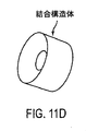
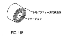
別の観点では、実施形態は、眼を計測する方法を提供する。この方法は、角膜トポグラフィー測定構造体を患者インターフェース構造体に結合して当該角膜トポグラフィー測定構造体を眼の前に配置するというステップを含む。角膜トポグラフィー測定構造体及び患者インターフェース構造体が眼から離れている状態で、眼が計測される。角膜トポグラフィー測定構造体は、患者インターフェース構造体から結合解除される。眼に接触させるために、患者インターフェース構造体は、患者インターフェースのコンポーネントに結合される。患者インターフェースに取り外し可能に結合される角膜トポグラフィー構造体での眼の測定に応じて、眼の乱視軸が決定される。 In another aspect, embodiments provide a method for measuring an eye. The method includes coupling the corneal topography measurement structure to a patient interface structure and placing the corneal topography measurement structure in front of the eye. The eye is measured with the corneal topography measurement structure and the patient interface structure away from the eye. The corneal topography measurement structure is decoupled from the patient interface structure. The patient interface structure is coupled to a patient interface component for contact with the eye. In response to eye measurements on a corneal topography structure that is removably coupled to the patient interface, the astigmatic axis of the eye is determined.
別の観点では、実施形態は、眼を計測する器械を提供する。この器械は、患者インターフェースを有する。トポグラフィー測定構造体が、眼に接触しないで眼を測定するよう患者インターフェースに結合されるよう、構成される。 In another aspect, embodiments provide an instrument for measuring an eye. The instrument has a patient interface. A topography measurement structure is configured to be coupled to the patient interface to measure the eye without touching the eye.
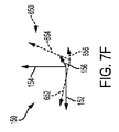
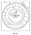
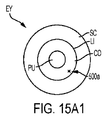
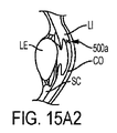
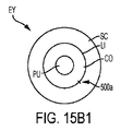
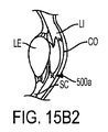
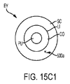
多くの実施形態において、眼は、ディスプレイのようなユーザインターフェースの助け無しで外科医や他のユーザが視覚的に特定することを希望し得る、軸、経線(meridian)または構造を含み得る。外科医や他のユーザは、治療されるべき眼の光学組織の近傍に視覚的なマーカー(識別子)が存在することを希望し得る。多くの実施形態では、可視化されるべき眼の軸、経線または構造は、ここで説明されるように眼の周囲上に基準マーク切開でマーキングされ得る。基準マーク切開は、好適には、選択された軸の視認可能なマークを提供する。これにより、視覚的調査によってその位置及び方向が正確に判定され得る。視覚的調査は、例えばマイクロスコープによる拡大下での視覚的調査を含む。 In many embodiments, the eye may include an axis, meridian or structure that a surgeon or other user may wish to visually identify without the aid of a user interface such as a display. Surgeons and other users may wish to have a visual marker (identifier) in the vicinity of the optical tissue of the eye to be treated. In many embodiments, the axis, meridian or structure of the eye to be visualized can be marked with a fiducial mark incision on the perimeter of the eye as described herein. The fiducial mark incision preferably provides a visible mark on the selected axis. Thereby, the position and direction can be accurately determined by visual inspection. Visual surveys include visual surveys under magnification with a microscope, for example.
例えば、乱視の眼において、外科医または他のユーザは、白内障の手術中の眼内への円環状のIOLのアラインメントのため、角膜の最も険しい経線を可視化することを希望し得る。最も険しい経線は、角膜トポグラファーによって特定され得る。患者の眼の角膜の険しい軸に沿って配置される放射状の基準マーク切開が、ここでは円環状の基準マーク切開(あるいは「円環状の基準マーク」)として言及される。円環状の基準マーク切開の設置は、白内障手術中に、治療する外科医が、円環状のIOLを眼の険しい軸と整列させることを許容する。円環状の基準マークの利点は、マーク設置の際の手動誤差の低減を含む。レーザマークは、より長い持続時間に亘って視認可能であり、患者−ユーザが実施する必要がある測定の数が最小化される。 For example, in an astigmatic eye, a surgeon or other user may wish to visualize the steepest meridian of the cornea due to the alignment of an annular IOL into the eye during cataract surgery. The steepest meridian can be identified by the corneal topographer. A radial fiducial mark incision placed along the steep axis of the cornea of the patient's eye is referred to herein as an annular fiducial mark incision (or “annular fiducial mark”). The placement of an annular fiducial mark incision allows the treating surgeon to align the annular IOL with the steep axis of the eye during cataract surgery. The advantages of an annular fiducial mark include a reduction in manual error during mark placement. The laser mark is visible over a longer duration, minimizing the number of measurements that the patient-user needs to perform.
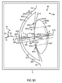
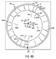
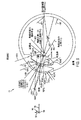
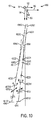
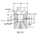
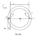
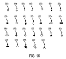
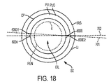
基準マーク切開は、一般に、選択された軸に沿って眼の周囲上に配置され、角膜縁、虹彩またはスキャンされた水晶体嚢の1つの上にセンタリングされた角膜内の2つの小さい放射状の切開を含む。マークは、好適には、軸の中心回り180°に配置され、より好適には、直径方向に対向するように配置される。基準マーク切開は、中心を通る水平線と、光学領域によって規定された内径と厚み長さとを有する水平リングと、の交線及び幅によって規定された2つの線分要素として生成され得る。これら2つの線分要素は、角膜内に置かれるべき基準マークのxy突出部である長さ(ミクロン単位)を有し、好適には、基質内であって眼の光学領域の外側にある。基準マークの他の形状及び設置は、図15乃至図19及びそれらの関連する説明に示されており、2014年4月17日に出願された米国特許第14/255,430号(発明の名称:LASER FIDUCIALS FOR AXIS ALIGNMENT IN CATARACT SURGERY)に記載されている。 A fiducial mark incision is typically placed on the periphery of the eye along a selected axis and consists of two small radial incisions in the cornea centered on one of the limbus, iris or scanned lens capsule. Including. The mark is preferably arranged at 180 ° around the center of the axis, and more preferably arranged so as to face the diameter direction. The fiducial mark incision may be generated as two line segment elements defined by the intersection and width of a horizontal line through the center and a horizontal ring having an inner diameter and thickness length defined by the optical region. These two line segment elements have a length (in microns) that is the xy protrusion of the fiducial mark to be placed in the cornea and is preferably within the matrix and outside the optical region of the eye. Other shapes and installations of fiducial marks are shown in FIGS. 15-19 and their related descriptions, and are US Pat. No. 14 / 255,430 filed Apr. 17, 2014 (Title of Invention). : LASER FIDUCIALS FOR AXIS ALIGNMENT IN CATARACT SURGERY).
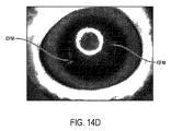
基準マーク切開は、一般に、角膜の光学特性を変更しない。好適には、切開の長さは5mm未満であり、好適には2.5mm未満であり、より好適には1.5mm以下である。1.5mm以下の切開長さが、迅速に治癒して好適な誤差マージンを伴って光学特性を変更しないという光学的に視認可能な切開を提供する、ということが見出された。基準マーク切開を生成する際に用いられるパルスエネルギーは、一般に、嚢切開、角膜縁弛緩切開、及び水晶体破砕のために用いられるよりも小さく、好適には、0.5マイクロジュールと10マイクロジュールの間、より好適には3マイクロジュールと8マイクロジュールの間、より好適には4マイクロジュールと6マイクロジュールの間である。図14Dは、治療後1時間でも明瞭に視認可能であることを示す、豚の眼の基準マークを図示している。 A fiducial mark incision generally does not change the optical properties of the cornea. Preferably, the length of the incision is less than 5 mm, preferably less than 2.5 mm, more preferably 1.5 mm or less. It has been found that an incision length of 1.5 mm or less provides an optically visible incision that heals quickly and does not change the optical properties with a suitable error margin. The pulse energy used in generating the fiducial mark incision is generally smaller than that used for capsulotomy, limbal relaxation incision, and lens fragmentation, preferably between 0.5 microjoules and 10 microjoules. More preferably between 3 and 8 microjoules, more preferably between 4 and 6 microjoules. FIG. 14D illustrates a pig eye fiducial mark indicating that it is clearly visible even 1 hour after treatment.
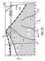
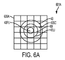
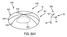
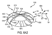
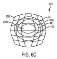
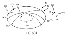
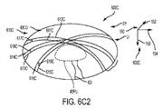
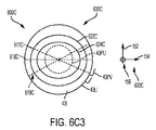
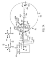
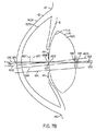
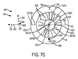
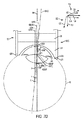
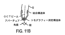
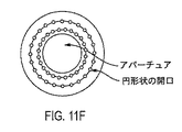
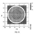
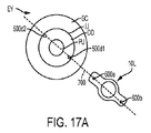
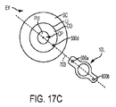
視覚的な特定が所望される軸、経線または構造は、好適には、角膜トポグラフィーまたはトモグラフィーによって測定される。角膜トポグラフィー測定構造は、例えばリング形状またはディスク形状の照明器のような外部照明構造を含み得る。当該照明構造は、眼を照明して、当該照明構造のリング形状またはディスク形状の仮想画像を形成し、角膜の乱視軸及び最も険しい経線が、眼の仮想画像の測定に基づいて決定される。外部照明器は、眼の測定のために患者インターフェースに結合するように構成され得て、眼が患者インターフェースにドッキングされる時に除去され得る。 The axis, meridian or structure for which visual identification is desired is preferably measured by corneal topography or tomography. The corneal topography measurement structure may include an external illumination structure such as a ring or disk shaped illuminator. The illumination structure illuminates the eye to form a ring-shaped or disk-shaped virtual image of the illumination structure, and the astigmatic axis of the cornea and the steepest meridian are determined based on measurements of the virtual image of the eye. The external illuminator can be configured to couple to the patient interface for eye measurements and can be removed when the eye is docked to the patient interface.
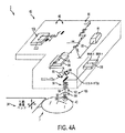
角膜トポグラファーによる測定の後、患者インターフェースは、一般に、患者の眼のシステムに対する位置を保持するべく利用される。角膜トポグラフィーの測定と患者インターフェースの設置との間に、患者の眼は動くことがあり得て、それは視覚的特定が所望される軸、経線または構造の移動に帰結する。多くの実施形態において、虹彩登録が、角膜トポグラフィー測定の間のその非接触位置に対して、ユーザインターフェースが取り付けられる時の眼の回転角(cyclotorsional angle)を決定するために用いられる。例えば、虹彩の第1画像が、患者インターフェースが眼に接触する前に、第1カメラで得られて、虹彩の第2画像が、患者インターフェースが眼に接触する時に得られる。第1画像及び第2画像が、多くの態様のうちの1またはそれ以上において登録され得る。プロセッサは、例えば画像マッチングアルゴリズムまたはパターン認識アルゴリズムによって眼の回転角を決定するための命令(指令)と共に構成され得る。当該アルゴリズムの命令(指令)を有するプロセッサは、ここで説明されるように眼の軸との関連で第1画像のパターンを特定するように、且つ、眼の回転角を決定するべく第2画像のパターンの位置を特定するように、構成され得る。眼の回転角は、その後、患者インターフェースが取り付けられた時の眼の位置、視覚的特定が所望される軸、経線または構成を含む、を決定するために利用され得る。 After measurement by the corneal topographer, the patient interface is typically utilized to maintain the position of the patient's eye relative to the system. During the measurement of the corneal topography and the placement of the patient interface, the patient's eyes can move, resulting in movement of the axis, meridian or structure where visual identification is desired. In many embodiments, the iris registration is used to determine the angle of eye rotation when the user interface is attached to its non-contact position during corneal topography measurements. For example, a first image of the iris is obtained with a first camera before the patient interface contacts the eye, and a second image of the iris is obtained when the patient interface contacts the eye. The first image and the second image may be registered in one or more of many aspects. The processor may be configured with instructions (commands) for determining the eye rotation angle, for example by an image matching algorithm or a pattern recognition algorithm. A processor having instructions (commands) of the algorithm, as described herein, identifies the pattern of the first image in relation to the eye axis and determines the second image to determine the eye rotation angle. Can be configured to identify the position of the pattern. The eye rotation angle can then be utilized to determine the position of the eye when the patient interface is attached, including the axis, meridian or configuration for which visual identification is desired.
その後、基準マーク切開は、患者インターフェースが患者の眼に固定された状態で、前記軸、経線または構造に沿って正確に切開され得る。レーザ手術システムによる付加的な切開は、嚢切開、角膜縁弛緩切開、及び、水晶体破砕及び/または細分化パターン、の1またはそれ以上を含み得る。関連する組織の切開が完了した後、患者インターフェースが除去され得て、水晶体が続いて除去され得る。 The fiducial mark incision can then be accurately incised along the axis, meridian or structure with the patient interface secured to the patient's eye. Additional incisions by the laser surgical system may include one or more of capsulotomy, limbal relaxation incision, and lens fragmentation and / or fragmentation patterns. After the associated tissue incision is complete, the patient interface can be removed and the lens can subsequently be removed.
(詳細な説明) (Detailed explanation)
本開示内容、即ち本発明の要旨は、以下の特許出願、即ち、2008年3月3日に出願された米国特許出願第12/048,182号(発明の名称:METHOD AND APPARATUS FOR CRREATING INCISIONS TO IMPROVE INTRAOCULAR LENS PLACEMENT)(代理人事件番号43406‐707/201)、2008年3月13日に出願された米国特許出願第12/048,186号(発明の名称:METHOD AND APPARATUS FOR CREATING OCULAR SURGICAL AND RELAXING INCISIONS)(代理人事件番号43406‐713/201)、2012年11月2日に出願された米国特許出願第61/722,064号(発明の名称:LASER EYE SURGERY SYSTEM DALIBRATION)(代理人事件番号43406‐728/101)、2013年4月18日に出願された米国特許出願第61/813,613号(発明の名称:CORNEAL TOPOGRAPHY MEASUREMENT AND ALIGNMENT OF CORNEAL SURGICAL PROCEDURES )(代理人事件番号42406‐746.101)、2013年3月15日に出願された米国特許出願第61/788,201号(発明の名称:MICROFEMTOTOMY METHODS AND SYSTEMS)(代理人事件番号43406‐704.101)、2013年4月17日に出願された米国特許出願第61/813,172号(発明の名称:LASER FIDUCIALS FOR ALIGNMENT IN CATARACT SURGERY)(代理人事件番号U.S.43406‐747.101)に関し、これらの特許文献を参照により引用し、これらの開示内容全体を本明細書の一部とし、かかる開示内容全体は、開示する実施形態に従って組み合わせに適している。 The present disclosure, i.e., the gist of the present invention, is disclosed in the following patent application, i.e., U.S. Patent Application No. 12 / 048,182 filed on March 3, 2008 (Title: METHOD AND APPARATUS FOR CRREATING INCISIONS TO IMPROVE INTRAOCULAR LENS PLACEMENT) (Attorney Case No. 43406-707 / 201), US Patent Application No. 12 / 048,186, filed March 13, 2008 (Invention name: METHOD AND APPARATUS FOR CREATING OCULAR SURGICAL AND RELAXING INCISIONS) (Attorney Case No. 43406-713 / 201), US Patent Application No. 61 / 722,064 (Title of Invention: LASER EYE SURGERY SYSTEM DALIBRATION) filed on November 2, 2012 (Attorney Case) No. 43406-728 / 101), US Patent Application No. 61 / 813,613 filed on April 18, 2013 (Title of Invention: CORNEAL TOPOGRAPHY MEASU REMENT AND ALIGNMENT OF CORNEAL SURGICAL PROCEDURES) (Attorney Case No. 42406-746.101), US Patent Application No. 61 / 788,201 filed March 15, 2013 (Title of Invention: MICROFEMTOTOMY METHODS AND SYSTEMS) (Attorney Case Number 43406-704.101), US Patent Application No. 61 / 813,172 filed on April 17, 2013 (Title of Invention: LASER FIDUCIALS FOR ALIGNMENT IN CATARACT SURGERY) U.S. 43406-747.101), which are incorporated herein by reference, the entire disclosures of which are incorporated herein by reference, and such disclosures are suitable for combination according to the disclosed embodiments. ing.
レーザ眼手術に関連付けられた方法及びシステムが開示される。多くの実施形態で、レーザが、角膜、水晶体嚢及び/又は水晶体核に正確な切開創を作るために用いられる。特にレーザ眼手術のための組織保持が参照されるが、本明細書において説明する実施形態は、多くのやり方のうちの1つ又は2つ以上のやり方で、多くの外科的処置及び外科用器具、例えば整形外科、ロボット手術及びミクロケラトーム(微小角膜切刀)に、使用できる。 Methods and systems associated with laser eye surgery are disclosed. In many embodiments, a laser is used to make an accurate incision in the cornea, lens capsule and / or lens nucleus. Reference is made in particular to tissue retention for laser eye surgery, but the embodiments described herein can be used in many surgical procedures and surgical instruments in one or more of many ways. For example, orthopedic surgery, robotic surgery and microkeratome.
本明細書において説明する実施形態は、特に、組織を治療するのに好適であり、例えば、組織の外科的治療に用いられる。多くの実施形態で、組織は、光学的に透明な組織、例えば眼の組織を含む。本明細書において説明する実施形態を、多くのやり方で、多くの公知の屈折異常外科的処置、例えば白内障手術や角膜切開術、のうちの1つ又は2つ以上と、組み合わせることができる。かかる外科的処置としては、例えばレーザ角膜内切削形成術(以下、“LASIK”という)、全てのレーザLASIK、フェムトLASIK、角膜形成術、乱視角膜切開術、角膜弛緩切開術(以下、“CRI”という)、角膜縁(リンバス)弛緩切開術(以下、“LRI”という)、光反応角膜整形手術(以下、“PRK”という)、及び小切開創水晶体摘出(以下、“SMILE”という)が挙げられる。 The embodiments described herein are particularly suitable for treating tissue, for example, for surgical treatment of tissue. In many embodiments, the tissue includes optically transparent tissue, such as ocular tissue. The embodiments described herein can be combined in many ways with one or more of many known refractive refractive surgical procedures, such as cataract surgery or keratotomy. Such surgical procedures include, for example, laser intracorneal cutting (hereinafter referred to as “LASIK”), all laser LASIK, femto LASIK, keratoplasty, astigmatic keratotomy, corneal laxation (hereinafter “CRI”). Corneal marginal (limbus) relaxation incision (hereinafter referred to as “LRI”), photoreactive corneal plastic surgery (hereinafter referred to as “PRK”), and small incision lens extraction (hereinafter referred to as “SMILE”). It is done.
本明細書において説明する実施形態は、特に、眼内レンズ、例えば1つ又は2つ以上の公知の眼内レンズのコンポーネント、と組み合わせるのに好適である。公知の眼内レンズは、例えば遠近調節型眼内レンズ又は眼の収差を矯正するための眼内レンズ、例えば眼の遠近調節型収差矯正レンズのうちの1つ又は2つ以上である。本明細書において開示する実施形態を用いると、屈折異常外科的処置を例えば眼内レンズと組み合わせることができる。 The embodiments described herein are particularly suitable for combination with intraocular lenses, such as one or more known intraocular lens components. Known intraocular lenses are, for example, one or more of a accommodation type intraocular lens or an intraocular lens for correcting eye aberrations, eg, an eye accommodation type aberration correction lens. With the embodiments disclosed herein, refractive refractive surgical procedures can be combined with, for example, intraocular lenses.
本明細書において説明する実施形態は、配置されたIOLを本明細書において説明するように眼の1本又は2本以上の軸とアラインメント(位置合わせ)状態で保持するために、例えば、2013年3月15日に出願された米国特許出願第61/788,201号明細書(発明の名称:Microfemtotomy methods and systems)(代理人事件番号43406‐704.101)に記載されている水晶体嚢及び構造と組み合わせて、眼内レンズの構造を受け入れるよう寸法決めされた水晶体嚢の切開創を位置決めするために使用できる。この米国特許出願を参照により引用し、その開示内容全体を本明細書の一部とする。 Embodiments described herein may be used to hold a deployed IOL in alignment with one or more axes of an eye as described herein, eg, 2013. Lens capsule and structure described in US patent application Ser. No. 61 / 788,201 filed Mar. 15 (Title of Invention: Microfemtotomy methods and systems) (Attorney Incident Number 43406-704.101) Can be used to position a capsular incision sized to receive the structure of an intraocular lens. This US patent application is incorporated by reference, the entire disclosure of which is hereby incorporated by reference.
本明細書において説明する実施形態は、IOLの軸線を眼と位置合わせするために、本明細書において説明するように、眼の1本又は2本以上の軸と位置合わせされた眼上の基準マーキングを、例えば2013年4月17日に出願された米国特許出願第61/813,172号明細書(発明の名称:Laser fiducials for alignment in cataract surgery)(代理人事件番号U.S.43406‐747.101)に記載されているような基準マーキング及びレンズと組み合わせて、位置決めするために使用されるのが良い。 The embodiments described herein provide a reference on the eye that is aligned with one or more axes of the eye, as described herein, to align the axis of the IOL with the eye. For example, US Pat. No. 61 / 813,172 filed on Apr. 17, 2013 (title of the invention: Laser fiducials for alignment in cataract surgery) (agent case no. US 43406- 747.101) may be used for positioning in combination with reference markings and lenses.
物体のレーザ治療に関連付けられると共に眼手術、例えばレーザ眼手術、に利用できる方法及びシステムが開示される。レーザが、角膜、水晶体嚢、及び/又は水晶体核に正確な切開創を形成するために使用され得る。本明細書において説明する実施形態は、特に、物体、例えば組織、の切断の精度を高めるのに好適であると言える。 Disclosed are methods and systems that are associated with laser treatment of objects and that can be used for eye surgery, eg, laser eye surgery. A laser can be used to make an accurate incision in the cornea, lens capsule, and / or lens nucleus. The embodiments described herein may be particularly suitable for increasing the accuracy of cutting an object, such as tissue.
多くの実施形態で、眼に結合された患者インターフェースは、患者インターフェースを介して得られる眼の像のディストーション及び眼の測定値に影響を及ぼす。患者インターフェースは、角膜縁の近くで眼上に配置可能な吸引リングを有するのが良く、眼上への吸引リングの配置は、角膜のディストーションに影響を及ぼす場合がある。患者インターフェースは、光学的に透過性の構造、例えば平べったいプレート又はレンズ、を含むのが良く、光学的に透過性の構造は、第2の像のディストーションに影響を及ぼす場合がある。例えば、患者インターフェースは、患者インターフェースが眼から離隔されると共に眼が生まれつき備わった形態を備えている場合に撮られた眼の像と比較して、患者インターフェースを介して撮られた眼の像に樽形ディストーションを追加する場合がある。変形例として、患者インターフェースは、例えば糸巻形ディストーションを追加するよう設計されていても良い。本明細書において開示する実施形態は、特に、角膜から離隔された光学的に透過性の要素を有する患者インターフェースとの組み合わせに好適である。ガスの泡を光軸から遠ざけるよう角膜から離隔された光学的に透過性のレンズ構造の湾曲した下面は、治療の焦点深度及びレンジを増大させることができ、本明細書において開示する実施形態は、かかる患者インターフェースとの併用に最適である。 In many embodiments, the patient interface coupled to the eye affects the distortion of the eye image and the eye measurements obtained through the patient interface. The patient interface may have a suction ring that can be placed on the eye near the limbus, and placement of the suction ring on the eye may affect corneal distortion. The patient interface may include an optically transparent structure, such as a flat plate or lens, and the optically transparent structure may affect the distortion of the second image. For example, the patient interface is an image of the eye taken through the patient interface as compared to the image of the eye taken when the patient interface is separated from the eye and has an innate form. May add barrel distortion. As a variant, the patient interface may be designed to add, for example, a pincushion distortion. The embodiments disclosed herein are particularly suitable for combination with a patient interface having an optically transmissive element spaced from the cornea. The curved lower surface of the optically transmissive lens structure spaced from the cornea to keep the gas bubbles away from the optical axis can increase the depth of focus and range of the treatment, and the embodiments disclosed herein are: Ideal for use with such patient interfaces.
本明細書において開示する実施形態は又、角膜測定システムとの組み合わせに適している。角膜測定システムは、患者が患者支持体、例えばレーザ手術システムのベッド、で支持されたときに角膜を当該角膜測定システムで測定することができるレーザ手術システムのコンポーネントを含むのが良い。変形例として、角膜測定システムは、例えば外科医の診療所の別の部屋の中でレーザシステムから離隔された角膜測定システムを含むのが良い。 The embodiments disclosed herein are also suitable for combination with a corneal measurement system. The corneal measurement system may include a component of a laser surgical system that is capable of measuring the cornea with the corneal measurement system when the patient is supported on a patient support, such as a bed of the laser surgical system. Alternatively, the corneal measurement system may include a corneal measurement system that is spaced apart from the laser system, for example in a separate room of the surgeon's clinic.
本明細書において開示する実施形態は、先行技術のレーザ手術システム、例えばオプティメディカ(Optimedica)から市販されているCatalys (商標)及び類似のシステム、との組み合わせに好適である。かかるシステムは、本明細書において開示する教示に従って改造できると共に、眼をより正確に測定して治療するよう改造可能である。 The embodiments disclosed herein are suitable for combination with prior art laser surgical systems, such as Catalysts ™ and similar systems commercially available from Optimedica. Such systems can be modified in accordance with the teachings disclosed herein and can be modified to more accurately measure and treat the eye.
本明細書で用いられる同一の符号、例えば参照符号及び文字は、同一の要素を示している。 Identical symbols, such as reference symbols and characters, used in this specification indicate identical elements.
本明細書で用いられる「前方(又は前)」及び「後方(又は後)」という用語は、患者に対する既知の向きを示している。手術のための患者の向きに応じて、「前方(又は前)」及び「後方(又は後)」という用語は、例えば患者がベッド上に仰臥姿勢で横たわっている場合にそれぞれ、「上側」及び「下側」という用語と類似する場合がある。「遠位」及び「前方(又は前)」という用語は、ユーザから見た場合の構造の向きを意味する場合があり、従って、「近位」及び「遠位」という用語は、例えば眼上に配置された構造について言及する場合、「前方(又は前)」及び「後方(又は後)」に類似する場合がある。当業者であれば、本明細書において説明される方法及び器械の向きの、多くの変形を認識するであろう。「前方(又は前)」、「後方(又は後)」、「近位」、「遠位」、「上側」、及び「下側」は、単に例示として用いられているに過ぎない。 As used herein, the terms “front (or front)” and “back (or rear)” indicate a known orientation with respect to the patient. Depending on the patient's orientation for surgery, the terms “front (or front)” and “back (or rear)” refer to “upper” and “upper” respectively, for example, when the patient is lying in a supine position on a bed. It may be similar to the term “lower”. The terms “distal” and “forward (or front)” may refer to the orientation of the structure as viewed from the user, and thus the terms “proximal” and “distal” May refer to “front (or front)” and “back (or rear)”. Those skilled in the art will recognize many variations in the orientation of the methods and instruments described herein. “Front (or front)”, “back (or rear)”, “proximal”, “distal”, “upper”, and “lower” are merely used as examples.
本明細書で用いられる「第1」及び「第2」という用語は、構造及び方法を説明するために用いられており、構造及び方法の順序に関する限定を意味するものではない。かかる用語は、本明細書において提供される教示に基づいて、当業者には明らかなように、任意の順序であって良い。 As used herein, the terms “first” and “second” are used to describe structures and methods and do not imply limitations regarding the order of the structures and methods. The terms may be in any order, as will be apparent to those skilled in the art based on the teaching provided herein.
本明細書で用いられる眼の「前方(又は前)結節点」及び「後方(又は後)結節点」という用語は、1つの結節のところに狙いが定められた光線が眼によって反射される性質を有する場合があり、その結果、光線は、光軸に対して同一の角度をなして別の結節からきたように見える。 As used herein, the terms “front (or front) nodal point” and “back (or rear) nodal point” of the eye refer to the property that a light beam targeted at one nodule is reflected by the eye. So that the rays appear to come from different nodules at the same angle to the optical axis.
本明細書において開示する実施形態により、正確であり且つ実質的にディストーションのない角膜トポグラフィー測定及びその次のレーザ治療との統合が可能である。多くの実施形態において、少なくとも3つのステップを実施する手段が設けられる。 The embodiments disclosed herein allow for accurate and substantially distortion-free corneal topography measurements and integration with subsequent laser treatments. In many embodiments, means for performing at least three steps are provided.
1.測定システムの捕捉範囲内での患者の眼の位置決め、 1. Positioning the patient's eye within the capture range of the measurement system,
2.角膜を正確に測定することができる測定システム、 2. A measurement system that can accurately measure the cornea,
3.測定時刻とレーザ治療時刻との間に起こり得る患者の眼の向きの多くの変化のうちの1つ又は2つ以上についての是正。 3. Correction for one or more of the many changes in patient eye orientation that may occur between the measurement time and the laser treatment time.
位置決め Positioning
多くの実施形態で、レーザ手術のための患者の位置決めは、患者のベッドの動き又はレーザシステムの動きによって行われる。オペレータは、ドッキング機構体を定位置に案内する側方及び軸方向位置の手動制御を有する。ドッキング機構体が存在しない場合、オペレータには、動きを案内する手段が提供されるのが良く、その結果、眼、例えば角膜が測定システムの動作レンジ内に配置されるようにする。これは、Catalys (商標)のサブシステム及び類似のシステムであって、本明細書において開示する実施形態に従って幾分かの改造を加えたもの、により達成できる。当初の患者の位置は、ビデオ画像を心合わせすることによって眼を側方位置に案内すると共に像を例えばビデオカメラで合焦させることによって眼を軸方向位置に案内するべく、ビデオカメラによって案内されるのが良い。このステップの終了時に、角膜は、トモグラフィーシステムの捕捉レンジ内に位置する。トモグラフィーシステムは、本明細書において説明する多くのトモグラフィーシステムのうちの1つ又は2つ以上を含むのが良く、かかるトモグラフィーシステムは、例えば、光干渉トモグラフィーシステム(以下、“OCT”システムという)、シャインプルーク(Scheimpflug)画像化システム、低コヒーレンス反射光測定システム、又は走査型共焦点スポット画像化システムを含むのが良い。トモグラフィーシステム、例えばOCTシステムは、角膜の軸方向位置を測定するために用いられ、適当なディスプレイが最終の正確な位置決めのためのオペレータによる誘導を可能にする。 In many embodiments, patient positioning for laser surgery is performed by movement of the patient's bed or movement of the laser system. The operator has manual control of the lateral and axial positions that guide the docking mechanism to a fixed position. In the absence of a docking mechanism, the operator may be provided with a means to guide the movement so that the eye, eg the cornea, is placed within the operating range of the measurement system. This can be achieved with the Catalyst ™ subsystem and similar systems, with some modifications according to the embodiments disclosed herein. The initial patient position is guided by the video camera to guide the eye to a lateral position by aligning the video images and to guide the eye to an axial position by focusing the image, for example with a video camera. It is good. At the end of this step, the cornea is located within the capture range of the tomography system. The tomography system may include one or more of the many tomography systems described herein, such as an optical interference tomography system (hereinafter “OCT” system), It may include a Scheimpflug imaging system, a low coherence reflected light measurement system, or a scanning confocal spot imaging system. A tomographic system, such as an OCT system, is used to measure the axial position of the cornea and an appropriate display allows guidance by the operator for final accurate positioning.
多くの実施形態で、ビデオ及びOCTシステムは、ドッキングシステムと協働するよう構成され、当該ドッキングシステムは、光学系の光路中に追加の光学素子及び液体媒体を有し、ドッキング機構光学系及びインターフェース媒体、例えば液体又は粘弾性物質、なしでの動作を計算に入れるようレーザシステムの合焦アルゴリズムを調節することが有益な場合がある。 In many embodiments, the video and OCT system is configured to cooperate with a docking system, the docking system having additional optical elements and liquid media in the optical path of the optical system, and docking mechanism optics and interfaces It may be beneficial to adjust the focusing algorithm of the laser system to account for operation without a medium, such as a liquid or viscoelastic material.
測定 Measurement
多くの実施形態で、レーザシステムは、例えば本明細書において説明するトモグラフィーにより、治療対象の眼表面をマッピングするサブシステムを含む。測定ステップは、好ましくは、眼が正確に位置決めされたときに行われる。オプションとして、固視光を導入して、患者が眼を固定された角度で固定された方向に向けた状態に保つのを助けるのが良い。測定データ捕捉が十分に迅速であり、例えば1秒のオーダである場合、固視光は、有益ではない場合がある。角膜表面の多数回のトモグラフィー走査、例えばOCTを短時間で収集することができる。多数回の走査により、データの精度が高められると共に、角膜のトポグラフィーデータを提供することができる。走査の事後処理を用いると、潜在的な眼の動きを除くことができ、測定精度が向上する。 In many embodiments, the laser system includes a subsystem that maps the surface of the eye to be treated, for example, by tomography as described herein. The measuring step is preferably performed when the eye is accurately positioned. Optionally, fixation light may be introduced to help the patient keep the eye in a fixed direction at a fixed angle. If measurement data acquisition is fast enough, for example on the order of 1 second, fixation light may not be beneficial. Multiple tomographic scans of the corneal surface, such as OCT, can be collected in a short time. Multiple scans can improve data accuracy and provide corneal topography data. Using post-scan processing can eliminate potential eye movement and improve measurement accuracy.
角膜表面をマッピングすると、多項式フィッティングアルゴリズム又は他のフィッティングアルゴリズムを用いて、角膜の有用なパラメータ、例えば角膜の光学屈折力、乱視軸角度、及び乱視の大きさのうちの1つ又は2つ以上、を計算することができる。 Mapping the corneal surface, using a polynomial fitting algorithm or other fitting algorithm, can use one or more of the useful parameters of the cornea, such as the optical power of the cornea, the astigmatic axis angle, and the astigmatism magnitude, Can be calculated.
光学組織表面をマッピングするのに適したフィッティングアルゴリズムの例としては、楕円表面、フーリエ変換、多項式、球面調和関数、テーラー多項式、ウェーブレット変換、又はゼルニケ多項式が挙げられる。多くの実施形態で、眼の光学組織表面の3次元エレベーションプロフィールデータが提供され、当該データが光学組織表面にフィッティングされる。光学組織表面は、例えば角膜の前面、角膜の後面、水晶体嚢の前面、水晶体嚢の後面、水晶体皮質の前面、水晶体皮質の後面、水晶体核の前面、水晶体核の後面、実質的に一定の屈折率を有する水晶体の1つ又は2つ以上の前面、実質的に一定の屈折率を有する水晶体の1つ又は2つ以上の後面、網膜表面、窩表面、視力を矯正するための標的組織表面、例えば標的角膜表面、眼内レンズの前面、又は眼内レンズの後面、のうちの1つ又は2つ以上を含むのが良い。レンズの屈折率は、約1.36から約1.41まで様々であるので、レンズの光学表面は、例えば同様な屈折率を有するレンズの1つ又は2つ以上の層を規定することができる。 Examples of fitting algorithms suitable for mapping optical tissue surfaces include elliptical surfaces, Fourier transforms, polynomials, spherical harmonics, Taylor polynomials, wavelet transforms, or Zernike polynomials. In many embodiments, three-dimensional elevation profile data of the optical tissue surface of the eye is provided and the data is fitted to the optical tissue surface. The optical tissue surface is, for example, the anterior surface of the cornea, the posterior surface of the cornea, the anterior surface of the lens capsule, the posterior surface of the lens capsule, the anterior surface of the lens cortex, the posterior surface of the lens cortex, the anterior surface of the lens nucleus, the posterior surface of the lens nucleus, and a substantially constant refraction. One or more anterior surfaces of the lens having a refractive index, one or more posterior surfaces of the lens having a substantially constant refractive index, a retinal surface, a fossa surface, a target tissue surface for correcting vision, For example, it may include one or more of the target corneal surface, the front surface of the intraocular lens, or the back surface of the intraocular lens. Since the refractive index of the lens varies from about 1.36 to about 1.41, the optical surface of the lens can define one or more layers of lenses having a similar refractive index, for example. .
多くの実施形態で、測定は、ここで説明されるように患者がレーザ眼手術システムの支持体上に置かれている時に眼に対して当該トポグラフィー測定構造を位置決めするべく患者インターフェースに取り外し可能に結合される角膜トポグラフィー構造によって実施される角膜トポグラフィー測定を含む。多くの実施形態で、トポグラフィー測定構造は、例えばリング形状またはディスク形状の照明器のような外部照明構造を含む。当該照明構造は、眼を照明して、当該照明構造のリング形状またはディスク形状の仮想画像を形成し、角膜の乱視軸及び最も険しい経線が、眼の仮想画像の測定に基づいて決定される。外部照明器は、眼の測定のために患者インターフェースに結合するように構成され得て、眼が患者インターフェースにドッキングされる時に除去され得る。リング構造の中央に明瞭な開口を有することは、特に重要であり得る場合に、ビデオシステムが利用されることを許容する。 In many embodiments, the measurement is removable to the patient interface to position the topographic measurement structure relative to the eye when the patient is placed on the support of a laser eye surgery system as described herein. A corneal topography measurement performed by a corneal topography structure coupled to the. In many embodiments, the topographic measurement structure includes an external illumination structure, such as a ring-shaped or disk-shaped illuminator. The illumination structure illuminates the eye to form a ring-shaped or disk-shaped virtual image of the illumination structure, and the astigmatic axis of the cornea and the steepest meridian are determined based on measurements of the virtual image of the eye. The external illuminator can be configured to couple to the patient interface for eye measurements and can be removed when the eye is docked to the patient interface. Having a clear opening in the center of the ring structure allows the video system to be utilized, where it can be particularly important.
患者のトポグラフィーが測定されて、例えば最も険しい経線を含む乱視軸が決定される時、トポグラフィー測定システムは、ここで説明されるように、患者インターフェース構造から結合解除され得て、患者インターフェースは眼に結合され得る。患者インターフェースが適用されると、レーザの焦点領域が患者の角膜内でスキャンされ、乱視軸に沿って、好適には最も険しい経線に沿って、円環状の基準マークを形成する。 When the patient's topography is measured and, for example, the astigmatic axis containing the steepest meridian is determined, the topography measurement system can be decoupled from the patient interface structure as described herein, and the patient interface is Can be coupled to the eye. When the patient interface is applied, the focal region of the laser is scanned in the patient's cornea to form an annular reference mark along the astigmatic axis, preferably along the steepest meridian.
座標系変換 Coordinate system conversion
多くの実施形態で、患者の眼が治療のためにドッキングされると、眼は、レーザシステム座標に対して位置又は回転のうちの1つ又は2つ以上を変化させる。位置は、3つの位置寸法を含むのが良く、回転は、3つの回転寸法を含むのが良く、回転又は向きの変化は、少なくとも幾つかの実施形態で全部で6つの自由度を含むのが良い。位置又は向きのうちの1つ又は2つ以上の当該変化は、患者の頭の動きや眼球運動の結果である場合があり、或いは、眼と患者インターフェースとのドッキングの際に加えられる力に関連付けられる場合がある。乱視軸角度のような角膜測定値を新たな座標系に変換することが、有用な場合がある。これを達成する数種類の方法が存在する。 In many embodiments, when the patient's eye is docked for treatment, the eye changes one or more of its position or rotation relative to the laser system coordinates. The position may include three positional dimensions, the rotation may include three rotational dimensions, and the rotation or orientation change may include a total of six degrees of freedom in at least some embodiments. good. The change in one or more of position or orientation may be the result of patient head movement or eye movement, or is related to the force applied when docking the eye with the patient interface. May be. It may be useful to convert a corneal measurement such as an astigmatic axis angle to a new coordinate system. There are several ways to accomplish this.
一方法では、オペレータが、測定に先立って、インキドットで患者眼をマーク付けすることができる。インキドットは、典型的には、角膜の辺縁部上に直径方向に横切って位置決めされる。これらドットは、治療のためのドッキング後に画像化カメラによって収集され得て、座標変換を計算するために使用できる。 In one method, the operator can mark the patient's eye with ink dots prior to measurement. The ink dots are typically positioned diametrically across the limbus of the cornea. These dots can be collected by an imaging camera after docking for treatment and can be used to calculate coordinate transformations.
もう1つの方法は、角膜測定ステップの際に撮られたビデオ画像又はOCT走査で見える眼特徴を用いて、眼の位置及び向きを判定することである。この判定は、治療のためのドッキング後に撮られた第2の画像の特徴に対する第1の画像の特徴について、例えば相関により又は例えば識別により行われるのが良い。この識別又は相関は、ディジタル画像処理アルゴリズムによって、又は、オペレータにより手動で、実施できる。手動で行われる場合、オペレータにはディスプレイスクリーン上のオーバーラップした画像(測定及び治療ステップ)が与えられ、画像は、並進及び回転に関して手動で操作され、ついには、これら画像が可視的にマッチングされるようになる。画像操作データは、ディスプレイソフトウェアによって検出されて座標変換のために用いられる。 Another method is to determine the position and orientation of the eye using video images taken during the corneal measurement step or eye features visible in the OCT scan. This determination may be made with respect to the features of the first image relative to the features of the second image taken after docking for treatment, for example by correlation or by identification, for example. This identification or correlation can be performed by a digital image processing algorithm or manually by an operator. When done manually, the operator is given overlapping images (measurement and treatment steps) on the display screen, the images are manually manipulated with respect to translation and rotation, and finally these images are visually matched. Become so. Image manipulation data is detected by display software and used for coordinate transformation.
プロセッサシステムは、本明細書において説明する方法ステップのうちの1つ又は2つ以上を実施するコンピュータプログラムの命令を具体化した有形の媒体を含むのが良い。 The processor system may include a tangible medium that embodies the instructions of a computer program that performs one or more of the method steps described herein.
図1は、角膜、水晶体嚢、及び/又は水晶体核に正確な切開創を作るよう動作できる多くの実施形態としてのレーザ眼手術システム2を示している。システム2は、メインユニット4、患者チェア又は椅子6、デュアルファンクションフットスイッチ8、及びレーザフットスイッチ10を含む。
FIG. 1 shows a number of embodiments of a laser
メインユニット4は、システム2の多くの主要サブシステムを含む。例えば、外部から視認できるサブシステムは、タッチスクリーンディスプレイ制御パネル12、患者インターフェース組立体14、患者インターフェース真空接続部16、ドッキング制御キーパッド18、患者インターフェース無線認証(RFID)リーダ20、外部接続部22(例えば、ネットワーク、ビデオ出力、フットスイッチ、USBポート、ドアインターロック、及びAC電力)、レーザエミッション指示器24、非常時レーザ停止ボタン26、キースイッチ28、及び、USBデータポート30を含む。
The
患者チェア6は、ベース32、患者支持ベッド34、ヘッドレスト36、位置決め機構体、及び、ヘッドレスト36上に設けられた患者チェアジョイスティック制御部38、を含む。位置決め制御機構体は、ベース32と患者支持ベッド34とヘッドレスト36との間に結合されている。患者チェア6は、患者チェアジョイスティック制御部38を用いて3つの軸線(x,y,z)において調節され差し向けられる(方向付けられる)よう構成されている。ヘッドレスト36及び拘束システム(図示していないが、例えば、患者の額に係合する拘束ストラップ)は、手技中、患者の頭を安定化する。ヘッドレスト36は、患者に快適さをもたらすと共に患者の頭の動きを減少させる調節可能な頸部支持体を含む。ヘッドレスト36は、患者に快適さをもたらすと共に患者の頭のサイズのばらつきに対応するために、患者の頭の位置の調節を可能にするよう鉛直方向に調節可能であるように構成されている。
The
患者チェア6は、手動調節を用いて、患者の脚部、胴、及び頭の傾斜関節運動を許容する。患者チェア6は、患者負荷位置、吸引リング捕捉位置、及び患者治療位置に対応している。患者負荷位置では、チェア6は、患者チェアが直立位置に戻った状態で且つ患者フットレストが下降位置にある状態で、メインユニット4の下から回転する。吸引リング捕捉位置では、チェアは、患者チェアがもたれ位置に戻った状態で且つ患者フットレストが持ち上げ位置にある状態で、メインユニット4の下から回転する。患者治療位置では、チェアは、患者チェアがもたれ位置に戻った状態で且つ患者フットレストが持ち上げ位置にある状態で、メインユニット4の下に回転する。
The
患者チェア6は、意図しないチェアの運動を生じさせないようにする「チェアイネーブル(chair enable)」特徴を備えている。患者チェアジョイスティック38は、2つのやり方のうちのいずれにおいても使用可能にすることができる。第1に、患者チェアジョイスティック38は、ジョイスティックの頂部上に配置された「チェアイネーブル」ボタンを有する。「チェアイネーブル」ボタンを連続的に押すことによって、ジョイスティック38による患者チェア6の位置の制御をイネーブルにすることができる。変形例として、デュアルファンクションフットスイッチ8の左側フットスイッチ40を連続的に押すと、ジョイスティック38による患者チェア6の位置の制御をイネーブルにすることができる。
The
多くの実施形態で、患者制御ジョイスティック38は、比例制御器である。例えば、ジョイスティックを僅かな量動かすことにより、チェアがゆっくりと動くようにすることができる。ジョイスティックを多くの量動かすと、チェアは、速く動くことができる。ジョイスティックをその最大移動限度に保持すると、チェアは、最大チェア速度で動くことができる。有効チェア速度は、患者が患者インターフェース組立体14に近づくにつれて減少されることができる。
In many embodiments, the patient control joystick 38 is a proportional controller. For example, the chair can move slowly by moving the joystick a small amount. If you move the joystick a lot, the chair can move faster. Holding the joystick at its maximum travel limit allows the chair to move at maximum chair speed. The effective chair speed can be reduced as the patient approaches the
非常時停止ボタン26を押すと、全てのレーザ出力のエミッションを停止させ、患者をシステム2に結合している真空を解除し、そして患者チェア6をディスエーブルにすることができる。停止ボタン26は、キースイッチ28に隣接した状態でシステムフロントパネル上に設けられている。
Pressing the emergency stop button 26 stops all laser power emissions, releases the vacuum coupling the patient to the
キースイッチ28を用いると、システム2をイネーブルにすることができる。待機位置にあるとき、キーを取り外すことができ、するとシステムがディスエーブルになる。動作可能位置にあるとき、キーは、システム2への電力をイネーブルにする。
Using the key switch 28, the
デュアルファンクションフットスイッチ8は、左側フットスイッチ40及び右側フットスイッチ42を含むデュアルフットスイッチ組立体である。左側フットスイッチ40は、「チェアイネーブル」フットスイッチである。右側フットスイッチ42は、「真空ON」フットスイッチであり、このフットスイッチは、液体光学系インターフェース吸引リングを患者の眼に固定するよう真空をイネーブルにする。レーザフットスイッチ10は、システムがイネーブルにある状態で押されたときに治療レーザを作動させるシュラウド付きフットスイッチである。
The dual
多くの実施形態で、システム2は、外部通信接続部を含む。例えば、システム2は、当該システム2をネットワークに接続するネットワーク接続部(例えば、RJ45ネットワーク接続部)を含むのが良い。ネットワーク接続部を用いると、治療報告のネットワーク印刷、システム性能ログを見るためのリモートアクセス、及びシステム診断を実施するためのリモートアクセス、をイネーブルにすることができる。システム2は、当該システム2により実施される治療のビデオを出力するために用いることができるビデオ出力ポート(例えばHDMI(登録商標))を含むのが良い。出力ビデオは、例えば家族が見るため且つ/或いは訓練のため、外部モニタ上に表示するのが良い。出力ビデオは又、例えば永久記録保存目的で記録されるのが良い。システム2は、例えばデータ記憶装置への治療報告のエクスポートをイネーブルにするよう、1つ又は2つ以上のデータ出力ポート(例えば、USB)を含むのが良い。データ記憶装置上に記憶された治療報告は、任意適当な目的で、例えば、ユーザがネットワークを利用した印刷へのアクセス手段を持たない場合に外部コンピュータからの印刷のために、後でアクセスすることができる。
In many embodiments, the
図2は、患者眼43に結合されたシステム2の単純化されたブロック図である。患者眼43は、角膜43C、水晶体43L及び虹彩43Iを有する。虹彩43Iは、眼43とシステム2とのアラインメントを得るために使用できる眼43の瞳孔を定める。システム2は、切断レーザサブシステム44、レンジング(測距)サブシステム46、アラインメント誘導システム48、共用光学系50、患者インターフェース52、制御エレクトロニクス54、制御パネル/GUI56、ユーザインターフェース装置58、及び、通信経路60を含む。制御エレクトロニクス54は、通信経路60を介して、切断レーザサブシステム44、レンジングサブシステム46、アラインメント誘導サブシステム48、共用光学系50、患者インターフェース52、制御パネル/GUI56、及びユーザインターフェース装置58に作動的に結合されている。
FIG. 2 is a simplified block diagram of
多くの実施形態で、切断レーザサブシステム44は、フェムト秒(FS)レーザ技術を利用している。フェムト秒レーザ技術を用いることによって、短い持続時間(例えば、持続時間が約10-13秒)レーザパルス(エネルギーレベルがマイクロジュール範囲にある)を厳密に合焦された箇所に送り出して組織を破壊することができ、それにより、水晶体核の超音波断片化に必要なレベルと比較して且つ長い持続時間を有するレーザパルスと比較して、必要なエネルギーレベルを実質的に減少させることができる。
In many embodiments, the cutting
切断レーザサブシステム44は、システム2の構成に適した波長を有するレーザパルスを生じさせることができる。非限定的な例を挙げると、システム2は、1020nm〜1050nmの波長を有するレーザパルスを提供する切断レーザサブシステム44を使用するよう構成されているのが良い。例えば、切断レーザサブシステム44は、1030(±5)nm中心波長をもつダイオード励起固体形態を有するのが良い。
The cutting
切断レーザサブシステム44は、制御及び状態調節コンポーネントを含むのが良い。例えば、かかる制御コンポーネントは、例えばレーザパルスのエネルギー及びパルス列の平均電力を制御するためのビーム減衰器、レーザパルスを含むビームの断面空間広がりを制御するための固定アパーチュア、ビーム列のフラックス及び繰り返し率及びかくしてレーザパルスのエネルギーをモニタするための1つ又は2つ以上の電力モニタ、及びレーザパルスの伝送を可能にしたり遮断したりするためのシャッタ、のようなコンポーネントを含むのが良い。かかる状態調節コンポーネントは、レーザパルスを含むビームをシステム2の特性に適合させる調節可能なズーム組立体、及び、レーザパルスビームの位置及び/又は方向に関する変動性を許容してそれによりコンポーネントのばらつきのための裕度(tolerance)を増大させながらレーザパルスを或る距離にわたって伝えるための固定光学リレー、を含むのが良い。
The cutting
レンジングサブシステム46は、眼構造の空間配置状態を3つの寸法方向で測定するよう構成されている。測定される眼構造としては、角膜の前面及び後面や、水晶体嚢、虹彩及び角膜縁の前方部分及び後方部分、が挙げられる。多くの実施形態で、レンジングサブシステム46は、光干渉トモグラフィー(OCT)画像化を利用している。非限定的な例を挙げると、システム2は、780nm〜970nmの波長を用いたOCT画像化システムを使用するよう構成されるのが良い。例えば、レンジングサブシステム46は、810nm〜850nmの波長の広域スペクトルを採用したOCT画像化システムを含むのが良い。かかるOCT画像化システムは、眼内におけるOCT測定の有効深さを調節し、それにより深さが角膜の前面から水晶体嚢の後方部分までの範囲そしてこれを超える範囲にわたる眼の角膜及び眼の構造、の前方に位置する患者インターフェースの特徴を含むシステムコンポーネントの測定を可能にする、というように調節可能な基準経路長を採用するのが良い。
The ranging
アラインメント誘導サブシステム48は、システム2の光学コンポーネントを整列させるために用いられるレーザビームを生じさせるレーザダイオード又はガスレーザを含むのが良い。アラインメント誘導サブシステム48は、ドッキング及び治療中、患者の眼を位置合わせすると共に安定化するのを助けるための固視光を生じさせるLED又はレーザを含むのが良い。アラインメント誘導サブシステム48は、レーザ又はLED光源、及び、ビームをX,Y,及びZ方向に位置決めするために用いられるアクチュエータのアラインメント及び安定性をモニタするための検出器、を含むのが良い。アラインメント誘導サブシステム48は、患者の眼の画像化を可能にして患者インターフェース52への患者の眼43のドッキングを容易にするために使用できるビデオシステムを含むのが良い。ビデオシステムにより提供される画像化システムは又、GUIを介して切れ目の所在位置を指図するために使用できる。ビデオシステムにより提供される画像化は、更に、手技の進捗状況をモニタし、手技中における患者の眼43の運動(眼球運動)を追跡し、眼の構造、例えば瞳孔及び/又は角膜縁、の所在位置及びサイズを測定するために、レーザ眼手術手技中に使用可能である。
共用光学系50は、患者インターフェース52と、切断レーザサブシステム44、レンジングサブシステム46、及びアラインメント誘導サブシステム48の各々と、の間に設けられた共通伝搬経路を提供する。多くの実施形態で、共用光学系50は、それぞれのサブシステム(例えば、切断レーザサブシステム44及びアラインメント誘導サブシステム48)からの放出光を受け取って放出光の向きを共通伝搬経路に沿って患者インターフェースに向けるためのビームコンバイナを含む。多くの実施形態で、共用光学系50は、各レーザパルスを焦点に集束させ又は合焦させる対物レンズ組立体を含む。多くの実施形態で、共用光学系50は、それぞれの放出光を3つの寸法方向に走査するよう動作可能な走査機構体を含む。例えば、共用光学系は、XY‐走査機構体及びZ‐走査機構体を含むのが良い。XY‐走査機構体を用いると、それぞれの放出光を、当該それぞれの放出光の伝搬方向を横切る2つの寸法方向に走査することができる。Z‐走査機構体を用いると、眼43内の焦点の深さを変化させることができる。多くの実施形態で、走査機構体は、レーザダイオードと対物レンズとの間に設けられ、その結果、走査機構体は、レーザダイオードによって生じたアラインメントレーザビームを走査するために用いられるようになっている。これとは対照的に、多くの実施形態で、ビデオシステムは、走査機構体がビデオシステムにより得られた像に影響を及ぼすことがないように、走査機構体と対物レンズとの間に配置されている。
Shared
患者インターフェース52は、患者の眼43の位置をシステム2に対して拘束するために用いられる。多くの実施形態で、患者インターフェース52は、真空の作用で患者の眼43に取り付けられる吸引リングを採用している。吸引リングは、例えば真空を用いて当該吸引リングを患者インターフェース52に固定することで、患者インターフェース52に結合される。多くの実施形態で、患者インターフェース52は、患者の角膜の前面から鉛直に位置がずらされた後面を有する光学的に透過性の構造を含み、適当な液体(例えば、滅菌緩衝生理的食塩水(BSS)、例えばAlcon BSS(アルコン(Alcon )部品番号(351‐55005‐1)又は均等物)の領域が患者インターフェースレンズ後面及び患者の角膜に接触した状態でこれらの間に配置されており、かかる適当な液体領域は、共用光学系50と患者の眼43との間の伝送経路の一部をなしている。光学的に透過性の構造は、1つ又は2つ以上の湾曲した表面を有するレンズ96を含むのが良い。変形例として、患者インターフェース52は、1つ又は2つ以上の実質的に平坦な表面、例えば平行なプレート又はウェッジ、を有する光学的に透過性の構造を含んでも良い。多くの実施形態で、患者のインターフェースレンズは、使い捨てであり、これを任意適当な間隔で、例えば各眼治療前に、交換するのが良い。
The
制御エレクトロニクス54は、切断レーザサブシステム44、レンジングサブシステム46、アラインメント誘導サブシステム48、患者インターフェース52、制御パネル/GUI56及びユーザインターフェース装置58の動作を制御すると共に通信経路60を介してこれらからの入力を受け取ることができる。通信経路60は、任意適当な形態で具体化でき、かかる形態としては、制御エレクトロニクス54とそれぞれのシステムコンポーネントとの間の任意適当な共用又は専用の通信経路が挙げられる。制御エレクトロニクス54は、任意適当なコンポーネント、例えば1つ又は2つ以上のプロセッサ、1つ又は2つ以上の書き換え可能ゲートアレイ(FPGA)、及び1つ又は2つ以上のメモリ記憶装置、を含むのが良い。多くの実施形態で、制御エレクトロニクス54は、ユーザ指定の治療パラメータに従って術前計画を提供すると共にレーザ眼手術手技に対するユーザ管理を提供するよう、制御パネル/GUI56を制御する。
The
ユーザインターフェース装置58は、ユーザ入力を制御エレクトロニクス54に提供するのに適した任意適当なユーザ入力装置を含むことができる。例えば、ユーザインターフェース装置58は、例えばデュアルファンクションフットスイッチ8、レーザフットスイッチ10、ドッキング制御キーパッド18、患者インターフェース無線認証(RFID)リーダ20、非常時レーザ停止ボタン26、キースイッチ28、及び患者チェアジョイスティック制御部38、のような装置を含むのが良い。
図3Aは、システム2に含めることができる多くの実施形態としての組立体62を示す単純化されたブロック図である。組立体62は、切断レーザサブシステム44、レンジングサブシステム46、アラインメント誘導サブシステム48、共用光学系50、及び患者インターフェース52の好適な形態の非限定的な実施例であると共にこれらの統合例である。切断レーザサブシステム44、レンジングサブシステム46、アラインメント誘導サブシステム48、共用光学系50、及び患者インターフェース52の他の形態及び統合例が可能であり、これらは、当業者には明らかである。
FIG. 3A is a simplified block diagram illustrating an
組立体62は、光学ビームを患者の眼43中に投射して走査するよう動作可能である。切断レーザサブシステム44は、超高速(UF)レーザ64(例えば、フェムト秒レーザ)を含む。組立体62を用いて、患者の眼43内で、3つの寸法方向X、Y、及びZにおいて光学ビームを走査するのが良い。例えば、UFレーザ64によって生じる短パルスレーザ光を眼組織中に合焦させて誘電破壊を生じさせ、それにより光切断を焦点(焦点ゾーン)周りに生じさせるのが良く、それにより、光誘起プラズマの付近の組織が断裂する。組立体62では、レーザ光の波長は、800nmから1200nmまで様々であって良く、レーザ光のパルス幅は、10fsから10000fsまで様々であって良い。パルス繰り返し周波数も又、10kHzから500kHzまで様々であって良い。非標的組織に対する意図しない損傷に関する安全限度は、繰り返し率及びパルスエネルギーに関して上限を定める。しきい値エネルギー、手技を終了させるまでの時間、及び安定性は、パルスエネルギー及び繰り返し率に関して下限を定める場合がある。眼43内、具体的には眼の水晶体及び水晶体嚢内の、合焦スポットのピーク電力は、光学破壊を生じさせると共にプラズマ媒介アブレーションプロセスを開始させるのに十分である。レーザ光については近赤外波長が好ましく、その理由は、生物学的組織中の線形光吸収及び散乱が近赤外波長について減少するからである。一例として、レーザ64は、120kHz(±5%)の繰り返し率及び1〜20マイクロジュール範囲の個々のパルスエネルギーで600fs未満の持続時間を有するパルスを生じさせる、繰り返しパルス化1031nm装置であるのが良い。
The
切断レーザサブシステム44は、制御エレクトロニクス54及びユーザにより、制御パネル/GUI56及びユーザインターフェース装置58を介して制御され、それによりレーザパルスビーム66が生じる。制御パネル/GUI56は、システム動作パラメータを設定し、ユーザ入力を処理し、集められた情報、例えば眼組織の像、を表示すると共に患者の眼43内に形成されるべき切開創の描写を表示するために用いられる。
The cutting
生じたレーザパルスビーム66は、ズーム組立体68を通って進む。レーザパルスビーム66は、ユニットごとに、特にUFレーザ64が異なるレーザ製造業者から得られる場合、様々であって良い。例えば、レーザパルスビーム66のビーム直径は、ユニットごとに様々であって良い(例えば、±20%だけ)。ビームは又、ビーム品質、ビーム発散度、ビーム空間真円度、及び収差に関して、様々であって良い。多くの実施形態で、ズーム組立体68は、当該ズーム組立体68から出たレーザパルスビーム66がユニットごとに一貫したビーム直径及び発散度を有する、というように調整可能である。
The resulting
ズーム組立体68を出た後、レーザパルスビーム66は、減衰器70を通って進む。減衰器70は、レーザビームの透過率及びかくしてレーザパルスビーム66中のレーザパルスのエネルギーレベルを調整するために用いられる。減衰器70は、制御エレクトロニクス54を介して制御される。
After exiting the
減衰器70を出た後、レーザパルスビーム66は、アパーチュア72を通って進む。アパーチュア72は、レーザパルスビーム66の外側の有効直径を設定する。次に、ズームは、アパーチュア存在場所のところでのビームのサイズ及びかくして透過される光の量を定める。透過光の量は、高と低の両方が定められる。上限は、眼内で達成できる最も高い開口数(NA)を達成するための要件によって定められる。高NAは、非標的組織についての低いしきい値エネルギー及び大きな安全マージンを促進する。下限は、高い光学スループットに関する要件によって定められる。システム内の透過損失が多すぎると、これによりシステムの寿命が短くなる。というのは、レーザ出力及びシステムが経時的に劣化するからである。加うるに、このアパーチュアを通る透過量が一貫していることが、各手技に関する最適セッティングの決定(及び共用)における安定性を促進する。典型的には、最適性能を達成するためには、このアパーチュアを通る透過量は、88%〜92%に設定される。
After exiting the attenuator 70, the
アパーチュア72を出た後、レーザパルスビーム66は、2つの出力ピックオフ74を通って進む。各出力ピックオフ74は、各レーザパルスの一部分をそれぞれの出力モニタ76にそらすための部分反射ミラーを含むのが良い。2つの出力ピックオフ74(例えば、主要及び補助)及びそれぞれの主要及び補助出力モニタ76は、主要出力モニタ76の誤動作の場合に冗長性を提供するために用いられる。
After exiting
出力ピックオフ74を出た後、レーザパルスビーム66は、システム制御シャッタ78を通って進む。システム制御シャッタ78は、手技上及び安全上の理由でレーザパルスビーム66のオン/オフ制御を保証する。2つの出力ピックオフは、シャッタに先行して、ビームパワー、エネルギー及び繰り返し率のモニタリングをシャッタの開放のための前提条件として考慮する。
After exiting output pickoff 74,
システム制御シャッタ78を出た後、光ビームは、光学系リレーテレスコープ80を通って進む。光学系リレーテレスコープ80は、レーザパルスビーム66を或る距離にわたって伝搬させる一方でレーザパルスビーム66の位置的及び方向的変動性を許容し、それによりコンポーネントのばらつきに関する裕度を増大させる。一例として、光学リレーは、アパーチュア位置の像をxyガルボミラー位置の近くの共役位置に中継するケプラー型無焦点(アフォーカル)望遠鏡であるのが良い。この態様では、XYガルボ配置場所のところでのビームの位置は、アパーチュア位置のところでのビーム角度の変化に対して不変(無関係)である。同様に、シャッタは、リレーに先立つ必要はなく、リレーの後に続いても良く又はリレー内に含まれても良い。
After exiting the
光学系リレーテレスコープ80を出た後、レーザパルスビーム66は、共用光学系50に送られ、共用光学系50は、レーザパルスビーム66を患者インターフェース52まで伝搬させる。レーザパルスビーム66は、ビームコンバイナ82に入射し、ビームコンバイナ82は、レーザパルスビーム66を反射する一方でレンジングサブシステム46及びアラインメント誘導サブシステム(AIM)48からの光ビームを透過させる。
After exiting the
ビームコンバイナ82の次に、レーザパルスビーム66は、Z‐テレスコープ84を通って進み続ける。Z‐テレスコープ84は、Z軸に沿って患者の眼43内でレーザパルス66の合焦位置を走査するよう動作可能である。例えば、Z‐テレスコープ84は、2つのレンズ群(各レンズ群は、1つ又は2つ以上のレンズを含む)を有するガリレイ望遠鏡を含むのが良い。レンズ群のうちの一方は、Z‐テレスコープ84のコリメーション位置周りでZ軸に沿って動く。この態様では、患者の眼43内のスポットの焦点位置は、Z軸に沿って動く。一般に、レンズ群の動きと焦点の動きとの間には或る関係が存在する。例えば、Z‐テレスコープは、約2倍のビーム拡大比と、レンズ群の動きと焦点の動きとの間の1:1に近い関係と、を有するのが良い。眼座標系のZ軸におけるレンズの動きと焦点の動きとの間に成り立つ正確な関係は、一定の線形(比例)関係である必要はない。この動きは、非線形であっても良く、モデル又は測定からの較正を介して、或いは、これら両方の組み合わせを介して、定められても良い。変形例として、焦点の位置をZ軸に沿って調節するために他方のレンズ群をZ軸に沿って動かしても良い。Z‐テレスコープ84は、患者の眼43内でレーザパルスビーム66の焦点を走査するためのZ‐走査装置として機能する。Z‐テレスコープ84は、制御エレクトロニクス54によって自動的に且つ動的に制御されるのが良く、そして次に説明するX及びY走査装置とは別個独立であり又はこれと相互作用するよう選択可能である。
Following the
Z‐テレスコープ84を通過した後、レーザパルスビーム66は、X‐走査装置86に入射し、このX‐走査装置は、レーザパルスビーム66をX方向に走査するよう動作可能であり、X方向は、主としてZ軸を横切る方向であり且つレーザパルスビーム66の伝搬方向を横切る方向である。X‐走査装置86は、制御エレクトロニクス54によって制御され、このX‐走査装置は、適当なコンポーネント、例えば、モータ、ガルバノメータ(検流計)、又は任意の他の周知の光学可動装置、を含むのが良い。Xアクチュエータの動作の関数としてのビームの動きの関係は、一定又は線形である必要はない。この関係のモデル化若しくは較正測定又はこれら両方の組み合わせが決定され得て、これを用いてビームの所在位置を定める(方向付ける)ことができる。
After passing through the Z-
X‐走査装置86によって定められた後、レーザパルスビーム66は、Y‐走査装置88に入射し、このY‐走査装置は、レーザパルスビーム66をY方向に走査するよう動作可能であり、Y方向は、主としてX軸及びZ軸を横切る方向である。Y‐走査装置88は、制御エレクトロニクス54によって制御され、このY‐走査装置は、適当なコンポーネント、例えば、モータ、ガルバノメータ(検流計)、又は任意の他の周知の光学可動装置、を含むのが良い。Yアクチュエータの動作の関数としてのビームの動きの関係は、一定又は線形である必要はない。この関係のモデル化若しくは較正測定又はこれら両方の組み合わせが決定され得て、そしてこれを用いてビームの所在位置を定めることができる。変形例として、X‐走査装置86及びY‐走査装置88の機能は、Z軸及びレーザパルスビーム66の伝搬方向を横切る方向の2つの寸法方向にレーザパルスビーム66を走査するよう構成されたXY‐走査装置によって提供されても良い。X‐走査装置86及びY‐走査装置88は、レーザパルスビーム66の結果としての方向を変化させ、それにより患者の眼43内に位置するUF焦点の側方変位を生じさせる。
After being defined by the
Y‐走査装置88によって定められた後、レーザパルスビーム66は、ビームコンバイナ90を通過する。ビームコンバイナ90は、レーザパルスビーム66を透過させる一方で、光ビームをアラインメント誘導サブシステム48のビデオサブシステム92に反射したりこのビデオサブシステム92からの光ビームを反射したりするよう構成されている。
After being defined by Y-
ビームコンバイナ90を通過した後、レーザパルスビーム66は、対物レンズ組立体94を通過する。対物レンズ組立体94は、1つ又は2つ以上のレンズを含むのが良い。多くの実施形態で、対物レンズ組立体94は、多数のレンズを含む。対物レンズ組立体94の複雑さは、走査フィールドサイズ、合焦スポットサイズ、テレセントリシティ度、対物レンズ組立体94の近位側及び遠位側の両方の有効作業距離、並びに、収差制御量によって、高められる場合がある。
After passing through the beam combiner 90, the
対物レンズ組立体94を通過した後、レーザパルスビーム66は、患者インターフェース52を通過する。上述したように、多くの実施形態で、患者インターフェース52は、患者の角膜の前面から鉛直に位置がずらされた後面を有する患者インターフェースレンズ96を含み、適当な液体(例えば、滅菌緩衝生理的食塩水(BSS)、例えばAlcon BSS (アルコン(Alcon )部品番号(351‐55005‐1)又は均等物)の領域が患者インターフェースレンズ96の後面及び患者の角膜に接触した状態でこれらの間に配置されており、かかる適当な液体領域は、共用光学系50と患者の眼43との間の伝送経路の一部をなしている。
After passing through the
制御エレクトロニクス54の制御下にある共用光学系50は、照準、レンジング、及び治療走査パターンを自動的に生成することができる。かかるパターンは、光の単一スポット、光の多数のスポット、光の連続パターン、光の多数の連続パターン、及び/又はこれらの任意の組み合わせ、で構成されるのが良い。加うるに、照準パターン(以下に説明する照準ビーム108を用いる)は、治療パターン(レーザパルスビーム66を用いる)と同一である必要はないが、オプションとして、レーザパルスビーム66が患者の安全のために所望の標的範囲内にのみ送り出されるという確認をもたらすべく治療パターンの限界を指示する、というように用いられるのが良い。これは、例えば、照準パターンが意図した治療パターンの輪郭を提供するようにさせることによって行われるのが良い。このように、治療パターンの空間広がりは、個々のスポット自体の正確な所在位置が分からない場合であってもユーザに知られるようにすることができ、かくして、走査は、速度、効率、及び/又は精度に関して最適化される。この照準パターンは又、ユーザに対するその視認性を更に高めるために、明滅として知覚されるよう形成できる。同様に、レンジングビーム102は、治療ビーム又はパターンと同一である必要はない。レンジングビームは、標的表面を識別(特定)するのに足るほど十分でありさえすれば良い。これら表面は、角膜並びに水晶体の前面及び後面を含むのが良く、これら表面は、単一の曲率半径を有する球とみなされ得る。また、光学系は、アラインメント誘導によって共用され、ビデオサブシステムは、治療ビームによって共用されるビデオサブシステムと同一である必要はない。レーザパルスビーム66の位置決め及び性質及び/又はレーザパルスビーム66が眼43上に形成する走査パターンは、更に、患者及び/又は光学システムを位置決めするための入力装置、例えばジョイスティック又は任意の他の適当なユーザ入力装置(例えば、制御パネル/GUI56)、の使用によって制御できる。
The shared
制御エレクトロニクス54は、眼43内の標的構造を標的にすると共にレーザパルスビーム66が適当な場所に合焦されて意図しない状態で非標的組織を損傷させることがないことを保証するようにするように構成されるのが良い。本明細書において説明する画像化モダリティ及び技術、例えば上述の画像化モダリティ及び技術、又は超音波は、水晶体及び水晶体嚢の所在位置を突き止めると共にその厚さを測定するために用いられるのが良く、それによりレーザ合焦方法に高い精度をもたらすことができ、かかる方法としては、2Dパターニング及び3Dパターニングが挙げられる。レーザ合焦は又、1つ又は2つ以上の方法を用いることによって達成でき、かかる方法としては、照準ビームの直接観察、又は他の公知のオフサルミック又は医用画像化モダリティ、例えば上述の画像化モダリティ、及び/又はこれらの組み合わせが挙げられる。加うるに、レンジングサブシステム、例えばOCTは、患者インターフェースと関与する特徴又は観点を検出するために使用できる。特徴としては、ドッキング構造体及び使い捨てレンズの光学構造体上の基準場所、例えば、前面及び後面の所在位置が挙げられる。
The
図3の実施形態で、レンジングサブシステム46は、OCT画像化装置を含む。追加的に又は代替的に、OCT画像化以外の画像化モダリティを用いることができる。眼のOCT走査は、患者の眼43内の関心のある構造の空間配置状態(例えば、境界部上の箇所の3次元座標、例えばX、Y、及びZ)を測定するために使用できる。関心のあるかかる構造としては、例えば、角膜の前面、角膜の後面、水晶体嚢の前方部分、水晶体嚢の後方部分、水晶体の前面、水晶体の後面、虹彩、瞳孔、及び/又は角膜縁が挙げられる。制御エレクトロニクス54によって、関心のある構造及び/又は適当にマッチングする幾何学的モデル化、例えば表面及び曲線、の空間配置状態を生じさせることができ及び/或いは用いることができ、それにより次のレーザ補助手術手技をプログラムすると共に制御することができる。関心のある構造及び/又は適当にマッチングする幾何学的モデル化の空間配置状態は又、手技に関連付けられた多様なパラメータ、例えば、とりわけ、水晶体嚢の切断並びに水晶体皮質及び核の断片化のために用いられる焦平面の軸方向上限及び軸方向下限、及び、水晶体嚢の厚さ、を求めるために使用できる。
In the embodiment of FIG. 3, the ranging
図3のレンジングサブシステム46は、OCT光源及び検出装置98を含む。OCT光源及び検出装置98は、適当な広域スペクトルを持つ光を生成して放出する光源を含む。例えば、多くの実施形態で、OCT光源及び検出装置98は、810nm〜850nmの波長の広域スペクトルを持つ光を生成して放出する。生成されて放出された光は、シングルモード光ファイバ接続部によって装置98に結合される。
The ranging
OCT光源及び検出装置98から放出された光は、ビームコンバイナ100に通され、ビームコンバイナ100は、この光をサンプル部分102と基準部分104に分割する。サンプル部分102の大部分は、共用光学系50を通って透過される。サンプル部分の比較的僅かな部分が、患者インターフェース52及び/又は患者の眼43から反射されて共用光学系50を通って戻り、ビームコンバイナ100を通って戻り、そしてOCT光源及び検出装置98に入る。基準部分104は、調整可能な経路長を有する基準経路106に沿って伝えられる。基準経路106は、ビームコンバイナ100からの基準部分104を受け取り、この基準部分104を調節可能な経路長にわたって伝搬させ、そして基準部分104をビームコンバイナ100に戻すよう構成されており、ビームコンバイナ100は、次に、戻された基準部分104をOCT光源及び検出装置98に向けて戻す。次に、OCT光源及び検出装置98は、サンプル部分102の戻っている僅かな部分及び戻っている基準部分104を検出組立体中に差し向ける。検出組立体は、時間領域検出技術、周波数検出技術、又は単一点検出技術を採用する。例えば、周波数領域技術は、波長が830nmであり且つ帯域幅が10nmのOCTで用いることができる。
Light emitted from the OCT light source and
ビームコンバイナ82の次にUFレーザパルスビーム66といったん組み合わされると、OCTサンプル部分ビーム102は、共用光学系50及び患者インターフェース52を通る当該UFレーザパルスビーム66と一緒に共用経路を辿る。このように、OCTサンプル部分ビーム102は、一般に、UFレーザパルスビーム66の所在位置を表している。UFレーザビームと同様、OCTサンプル部分ビーム102は、Z‐テレスコープ84を通過し、そしてX‐走査装置86及びY‐走査装置88によって変向され、対物レンズ組立体94及び患者インターフェース52を通り、そして眼43内に入る。眼内における構造の反射及び散乱により、戻りビームが生じ、かかる戻りビームは、患者インターフェース52を通って戻り、共用光学系50を通って戻り、ビームコンバイナ100を通って戻り、そしてOCT光源及び検出装置98中に戻る。サンプル部分102の戻り反射光は、戻り基準部分104と組み合わされてOCT光源及び検出装置98の検出器部分中に差し向けられ、かかる検出器部分は、組み合わされた戻りビームに応じてOCT信号を生じさせる。生じたOCT信号は、制御エレクトロニクスによって解釈され、それにより患者の眼43内の関心のある構造の空間配置状態が判定される。生じたOCT信号は又、患者インターフェース52の位置及び向きを測定すると共に患者インターフェースレンズ96の後面と患者の眼43との間に液体が存在しているか否かを判定するために、制御エレクトロニクスによって解釈されるのが良い。
Once combined with the UF
OCT光源及び検出装置98は、基準経路106とサンプル経路との間の光路長の差を測定する原理で働く。したがって、UFレーザビームの焦点を変更するためのZ‐テレスコープ84の異なるセッティングは、眼内における患者インターフェース体積部の軸方向静止表面のためのサンプル経路の長さに影響を及ぼさない。というのは、この光路長は、Z‐テレスコープ84の異なるセッティングの関数として変化しないからである。レンジングサブシステム46は、光源及び検出方式に関連付けられた固有のZ範囲を有し、周波数領域検出方式の場合、Z範囲は、具体的には、分光計、波長、帯域幅、及び基準経路106の長さに関連付けられる。図3で用いられているレンジングサブシステム46の場合、Z範囲は、水性環境内において約4〜5mmである。この範囲を少なくとも20〜25mmに広げるには、レンジングサブシステム46内のステージZEDを介しての基準経路106の経路長の調節が必要である。サンプル経路長に影響を及ぼさないでOCTサンプル部分ビーム102をZ‐テレスコープ84中に通すことにより、OCT信号強度の最適化が考慮される。これは、OCTサンプル部分ビーム102を標的構造上に合焦させることによって達成される。合焦ビームは、シングルモード光ファイバを通って伝送可能な戻り反射ないし散乱信号を増大させると共に、当該合焦ビームの広がりの減少に起因して空間分解能を高める。サンプルOCTビームの焦点の変更は、基準経路106の経路長の変更とは無関係に達成できる。
The OCT light source and
サンプル部分102(例えば、810nm〜850nmの波長)及びUFレーザパルスビーム66(例えば、1020nm〜1050nm波長)が共用光学系50及び患者インターフェース52を通ってどのように伝搬するかにおける、例えば浸漬インデックス、屈折、収差(有色と単色の両方)のような影響に起因する基本的な差のために、OCT信号をUFレーザパルスビーム66の焦点場所に対して分析する際に注意が払われなければならない。OCT信号情報をUFレーザパルスビーム焦点場所に、そして更に相対的ないし絶対的な寸法上の量にマッチングさせるべく、X、Y、及びZの関数としての較正又は登録手順が実施され得る。
For example, the immersion index in how the sample portion 102 (eg, 810 nm to 850 nm wavelength) and the UF laser pulse beam 66 (eg, 1020 nm to 1050 nm wavelength) propagates through the shared
OCT干渉計の構成については、多くの好適な可能性が存在する。例えば、別の好適な構成としては、時間及び周波数領域方式、シングル及びデュアルビーム方法、被掃引源等が、米国特許第5,748,898号明細書、同第5,748,352号明細書、同第5,459,570号明細書、同第6,111,645号明細書、及び同第6,053,613号明細書に記載されている。 There are many suitable possibilities for the configuration of the OCT interferometer. For example, other suitable configurations include time and frequency domain systems, single and dual beam methods, swept sources, etc., US Pat. Nos. 5,748,898, 5,748,352. No. 5,459,570, No. 6,111,645, and No. 6,053,613.
システム2は、水晶体嚢及び角膜の前面及び後面の存在場所を突き止めてUFレーザパルスビーム66が所望の開口部のあらゆる箇所のところで水晶体嚢及び角膜上に合焦されることを保証するよう、設定されるのが良い。本明細書において説明する画像化モダリティ及び技術、例えば光干渉トモグラフィー(OCT)及び例えばプルキンエ画像化、シャインプルーク画像化、共焦点又は非線形光学顕微鏡、蛍光画像化、超音波、構造化光、立体画像化、又は他の公知のオフサルミック又は医用画像化モダリティ及び/又はこれらの組み合わせを用いると、水晶体、水晶体嚢及び角膜の、形状、幾何学的形状、周長、境界、及び/又は3次元存在場所を求めることができ、それにより2D及び3Dパターニングを含むレーザ合焦方法により高い精度を与えられる。レーザ合焦は又、1つ又は2つ以上の方法を用いて達成でき、かかる方法としては、照準ビームの直接観察又は他の公知のオフサルミック又は医用画像化モダリティ及びこれらの組み合わせ、例えば上述したモダリティ及び組み合わせ(これらには限定されない)、が挙げられる。
角膜、前眼房及び水晶体の光学画像化は、切断のためのパターンを作るために用いられるのと同一のレーザ及び/又は同一のスキャナを用いて達成できる。光学画像化を用いると、前及び後水晶体嚢の軸方向存在場所及び形状(及び厚さ)、白内障の水晶体核の境界、並びに、前眼房及び角膜の特徴の深さ、に関する情報を提供することができる。次に、この情報をレーザ3‐D走査システムにロードすることができ、又は、これを用いて眼の角膜、前眼房、及び水晶体の3次元モデル/表示/画像を生成することができると共に、かかる情報を用いると、手術手技で用いられる切断パターンを定めることができる。 Optical imaging of the cornea, anterior chamber and lens can be accomplished using the same laser and / or the same scanner that is used to create the pattern for cutting. Optical imaging provides information about the axial location and shape (and thickness) of the anterior and posterior lens capsule, the boundary of the cataractous lens nucleus, and the depth of anterior chamber and corneal features be able to. This information can then be loaded into a laser 3-D scanning system or can be used to generate a 3D model / display / image of the cornea, anterior chamber, and lens of the eye and Using such information, the cutting pattern used in the surgical procedure can be determined.
照準ビームの観察は又、UFレーザパルスビーム66の焦点を位置決めするのを助けるために使用できる。加うるに、赤外OCTサンプル部分ビーム102及びUFレーザパルスビーム66に代わる裸眼で見える照準ビームは、当該照準ビームが赤外ビームパラメータを正確に表示していることを条件として、アラインメントに役立ちうる。アラインメント誘導サブシステム48は、図3に示されている組立体62に含まれる。照準ビーム108は、照準ビーム光源110、例えば630〜650nm範囲のレーザダイオード、により生じる。
The aiming beam observation can also be used to help position the focus of the UF
照準ビーム光源110が照準ビーム108を生じさせると、照準ビーム108は、照準経路112に沿って共用光学系50に伝えられ、ここで、当該照準ビームの向きがビームコンバイナ114によって変えられる。ビームコンバイナ114によって偏向された後、照準ビーム108は、共用光学系50及び患者インターフェース52を通るUFレーザパルスビーム66と一緒に共用経路を辿る。このように、照準ビーム108は、UFレーザパルスビーム66の存在場所を表す。照準ビーム108は、Z‐テレスコープ84を通り、X‐走査装置86及びY‐走査装置88によって偏向され、ビームコンバイナ90を通り、対物レンズ組立体94及び患者インターフェース52を通り、そして患者の眼43中に入る。
When the aiming
ビデオサブシステム92は、患者インターフェース及び患者の眼の像を得るよう動作可能である。ビデオサブシステム92は、カメラ116、照明光源118、及びビームコンバイナ120を含む。ビデオサブシステム92は、既定の構造周り又はその内部におけるパターン心合わせを提供するために制御エレクトロニクス54によって使用できる像を集める。照明光源118は、一般に、広帯域且つ非干渉性であるのが良い。例えば、光源118は、多数のLEDを含むのが良い。照明光源118の波長は、好ましくは、700nm〜750nmであるが、照明光源118からの光をUFレーザパルスビーム66、OCTサンプルビーム102、及び照準ビーム108のためのビーム経路と組み合わせるビームコンバイナ90によって許容される波長範囲であればどのような波長範囲であっても良い(ビームコンバイナ90は、当該ビデオ波長を反射する一方でOCT及びUF波長を透過させる)。ビームコンバイナ90は、照準ビーム108の波長を部分的に透過させることができ、その結果、照準ビーム108は、カメラ116で見えるようになる。オプションとしての偏光素子が照明光源118の前に配置されるのが良く、かかるオプションとしての偏光素子は、信号を最適化するために用いられる。オプションとしての偏光素子は、例えば、直線偏光子、四分の一波長板、半波長板又は任意の組み合わせであるのが良い。追加のオプションとしての検光子がカメラの前に配置されるのが良い。偏光子と検光子の組み合わせは、交差直線偏光子であるのが良く、それにより、望まれていない表面、例えば対物レンズ表面、からのスペクトル反射光がなくなる一方で、標的表面、例えば眼の意図した構造、からの散乱光の通過が可能である。照明は又、照明源がビデオシステムの画像化部分の捕捉開口数の外部に位置する独立した表面に差し向けられるよう、暗視野形態内に位置するのが良い。変形例として、照明は又、明視野形態内に位置しても良い。暗視野形態と明視野形態との両方において、照明光源は、患者のための固定ビームとして使用されるのが良い。照明は又、患者の瞳孔を照明して瞳孔と虹彩との境界を強調して虹彩検出及び眼追跡を容易にするために使用できる。近赤外波長又はその帯域幅によって生じる疑似色画像が、許容可能であると言える。
システム2の組立体62は、例えば眼の測定、位置合わせ、及び治療中に患者が眼を向ける乃至固視するための可視光をもたらす固視灯119を含むのが良い。レンズ117が、固視灯を観察するのに適したバージェンス(vergence)で光を眼43に差し向けるよう設けられるのが良い。レンズ117から放出される光は、ビームスプリッタ121により反射されて、ビデオカメラ及び照明光学系の光路に沿って進む。
The
レンズ117は、例えば固定焦点レンズであっても良く又は可変焦点レンズであっても良い。レンズ117は、流体が角膜に接触したときの眼の屈折率の変化を是正するべく、眼上への流体の配置に先立って眼に入る光の第1の光学バージェンス及び眼上へのインターフェース流体の配置に続く第2のバージェンスを提供するような第1の形態を含むのが良い。第1の形態は、実質的に固定されたバージェンスを含んでも良く、或いは、例えば可変焦点レンズによって眼の屈折特性に合わせて調整される可変バージェンスを含んでも良い。正常視患者の場合、インターフェース流体の配置に先立って眼に入る光は、例えば、コリメートされ得る。レンズ117の第2の形態は、光を網膜上に合焦させるよう収束光ビームを眼に提供することができる。角膜が約40ジオプタ(以下、“D”)の光学屈折力を有すると共にインターフェース流体が眼の光学屈折力を実質的に減少させることができるので、第2の形態のレンズ117は、約40Dの正の光学屈折力を提供して光を眼の網膜上に合焦させることができる。この約40Dの正のバージェンスは、患者インターフェース流体が角膜上に配置されるときに患者が光を固視するよう求められる実施形態で極めて有用であると言える。
The
照明光源118からの照明光は、ビームコンバイナ120を通ってビームコンバイナ90に送られる。ビームコンバイナ90から、照明光は、対物レンズ組立体94及び患者インターフェース52を通って患者の眼43の方へ差し向けられる。眼43の種々の構造及び患者インターフェースから反射されて散乱された照明光は、患者インターフェース52を通って戻り、対物レンズ組立体94を通って戻り、そしてビームコンバイナ90に戻る。ビームコンバイナ90のところで、戻っている光は、ビームコンバイナ120に差し向けられて戻され、ここで、戻っている光の向きは、カメラ116の方へ変えられる。ビームコンバイナは、立方体であっても良く、板状であっても良く、又は薄膜状の要素であって良い。ビームコンバイナは又、スパイダーミラーの形態をしていても良く、それにより、照明光は、ミラーの外部広がりを超えて伝わり、一方で、像経路は、ミラーの内側反射面で反射する。変形例として、ビームコンバイナは、スクレーパミラーの形態をしていても良く、この場合、照明光は、穴を通って伝えられ、これに対し、像経路は、穴の外側に位置するミラーの反射面で反射する。カメラ116は、適当な画像化装置であって良く、例えば、適当なサイズのフォーマットのシリコンを利用した検出器アレイ(これには限定されない)であって良い。ビデオレンズは、カメラの検出器アレイ上に像を結び、他方、光学素子は、それぞれ偏光制御及び波長フィルタリングを可能にする。アパーチュア又は虹彩は、画像化NAの制御、かくして焦点深度、被写界深度及び分解能の制御を提供する。小さなアパーチュアは、患者ドッキング手順を助ける大きな被写界深度という利点を提供する。変形例として、照明経路とカメラ経路を切り替えることができる。さらに、照準光源110は、直接的には目に見えないが、ビデオサブシステム92を用いて捕捉されて表示できる赤外光を放出するよう構成され得る。
The illumination light from the
図3Bは、レーザシステム2の固定ビデオ光路中に組み込まれる凝視用灯(固視灯)を示しており、レーザシステム2内の組立体62は、眼を外部照明で照明するよう構成されている。眼の瞳孔及び角膜縁を見るためのビデオカメラは、虹彩をカメラセンサアレイ上に画像化するための複数のレンズを含むのが良い。複数のレンズは、第1の1つ又は2つ以上のレンズ111及び第2の1つ又は2つ以上のレンズ113を有するのが良い。ビームスプリッタ121は、例えば、第1のレンズと第2のレンズとの間に配置されるのが良い。ビームスプリッタ121は、例えば光学的に透明な材料の薄いプレートを有するのが良い。固視灯119から放出される光は、レンズ117を通って送られ、そして実質的に固定されたビデオ光路に沿って偏向される。眼42は、外部光源、例えば本明細書において説明する光学送り出しシステムの軸線99から離れて配置された光源、で照明されるのが良い。
FIG. 3B shows a staring lamp (fixation lamp) that is incorporated into the fixed video light path of the
図3Cは、眼のマッピングされた治療領域を示しており、当該治療領域は、角膜43C、水晶体43L、前水晶体嚢43LAC、後水晶体嚢43LPC、及び角膜縁43LIを含む。当該治療領域は、例えばレーザビーム品質、パルス幅、システム透過率、開口数、偏光、収差補正、及びアラインメントのような要因を組み込むために、コンピュータモデル化、例えば光線追跡及びフェーズド(位相)利用光学モデル化、によりマッピングされるのが良い。治療体積部は、患者インターフェースの光学的に透過性の構造体の前面からZ軸に沿って15mmを超える距離にわたって延びているものとして示されており、治療体積部は、角膜及び水晶体を含み、当該水晶体の治療体積部は、前水晶体嚢、後水晶体嚢、水晶体核及び皮質を含む。治療体積部は、角膜の中心から角膜縁を超えるところまで側方に延びている。体積部の側方寸法は、角膜縁の前方に位置するY輪郭及び角膜縁の後方に位置するX輪郭によって定められる。図示の治療体積部は、本明細書において説明する教示に基づいて当業者によって決定可能である。30mmに固定されたZL及び20mmに固定されたZLについての予想光学破壊の側方位置が示されている。Z方向寸法に沿う軸線99に対して横方向に延びるこれら表面は、軸線99から離れた側方の場所のところで光学破壊をもたらすようXガルボ及びYガルボの光学走査の場所に対応している。ZL‐30mm及びZL‐20mmについて光学破壊の走査経路の湾曲した非平面状の形状は、本明細書において説明するマッピング及びルックアップテーブルにより補正することができる。焦点の湾曲形状を光学破壊深度のワーピング(狂い)と呼ぶ場合があり、ルックアップテーブルは、例えば治療深度のワーピングを補償するよう、逆にワーピングされるか、又は違ったやり方で調節され得る。加うるに、モデルからの予想に特有のワーピングは、汎用ルックアップテーブル内に組み込まれるのが良く、この予想形態からの任意の更なる誤差は、当該誤差を相殺するための補正要素の測定及び適用によって示されていて、ルックアップテーブルのワーピングと呼ばれる場合がある。
FIG. 3C shows the mapped treatment area of the eye, which includes the
治療領域は、システムの角膜縁の近くのビームについて実験的に求められる光学破壊についてのしきい量の約4倍のレーザビームエネルギーを設定するために示されている。上述の増大したエネルギー又はマージンは、ビーム系が寄与要因の所与の変動性を取り扱うことを保証する。これら寄与要因としては、エネルギー、ビーム品質、システムの透過率、及びアラインメントに関する、レーザの寿命全体にわたる劣化が挙げられる。 The treatment area is shown to set a laser beam energy about four times the threshold for optical destruction that is experimentally determined for a beam near the corneal edge of the system. The increased energy or margin described above ensures that the beam system handles a given variability of contributing factors. These contributing factors include degradation over the lifetime of the laser in terms of energy, beam quality, system transmission, and alignment.
角膜の表面から離れて位置する患者インターフェースの光学的に透過性の構造体の後面の配置により、図示のような治療範囲の拡大を提供することができ、多くの実施形態で、光学的に透過性の構造体は、レンズを含む。変形実施形態で、光学的に透過性の構造体の後面は、例えば角膜上に配置されるのが良く、本明細書において説明するマッピング及びルックアップテーブルを用いると、患者治療に精度の向上をもたらすことができる。 Arrangement of the rear surface of the optically transmissive structure of the patient interface located away from the surface of the cornea can provide an extended treatment range as shown, and in many embodiments optically transmissive. The sex structure includes a lens. In an alternative embodiment, the rear surface of the optically transmissive structure may be located, for example, on the cornea, and using the mapping and lookup tables described herein can improve accuracy for patient treatment. Can bring.
患者インターフェースの光学的に透過性の構造体は、レンズ、プレート及びウェッジを製造するために用いられる多くの公知の光学的に透過性の材料のうちの1つ又は2つ以上、例えば、ガラス、BK‐7、プラスチック、アクリル樹脂、シリカ又は溶解石英のうちの1つ又は2つ以上、を有するのが良い。 The optically transparent structure of the patient interface can be one or more of many known optically transparent materials used to make lenses, plates and wedges, such as glass, One or more of BK-7, plastic, acrylic resin, silica or fused quartz may be included.
治療体積部のコンピュータマッピングは、オプションとして、本明細書において説明する構成システムの測定値を利用するマッピングにより調節できる。 The computer mapping of the treatment volume can optionally be adjusted by mapping utilizing the measurement values of the configuration system described herein.
図4Aは、レーザ送り出しシステム2の可動及びセンサコンポーネント相互間の対応関係を示している。可動コンポーネントは、本明細書において説明するレーザ送り出しシステム2の1つ又は2つ以上のコンポーネントを含むのが良い。レーザ送り出しシステムの可動コンポーネントは、距離ZL動くことができるズームレンズ、角度量Xm動くことができるXガルボミラー96、及び角度量Ym動くことができるYガルボミラー88、を含むのが良い。OCTシステムの可動コンポーネントは、距離ZEDにわたり基準経路106を動くことができるよう構成された可動OCT基準アームを含むのが良い。レーザ送り出しシステムのセンサコンポーネントは、X画素及びY画素、それぞれPixX及びPixY、を有するビデオカメラ、及びOCTシステムのセンサコンポーネント、例えば、本明細書において説明するスペクトル領域検出手段、を含むのが良い。ベッドを有するのが良い患者支持体は、患者Pの眼43をシステムのレーザシステム2及びシステムの軸線99に整列させるよう、3つの寸法方向において(3次元において)動くことができる。患者インターフェース組立体は、例えばシステム2及び眼43の軸線と整列するよう構成されたインターフェースレンズ96を有するのが良い光学的に透過性の構造体を含むのが良い。患者インターフェースレンズは、手術のために患者の眼43上に配置されるのが良く、光学的に透過性の構造体は、対物レンズ94から距離162を置いたところに配置されるのが良い。多くの実施形態で、光学的に透過性の構造体は、コンタクトレンズ光学距離162(以下“CLopt”)を置いたところに配置されるレンズ96を含む。光学的に透過性の構造体は、厚さ164を有し、この厚さ164は、例えばコンタクトレンズ96の厚さを含むのが良い。コンタクトレンズ96を有する光学的に透過性の構造体は、眼43に接触することができるが、多くの実施形態で、コンタクトレンズ168は、隙間168が当該レンズと角膜の頂との間に延びる状態で角膜から離隔され、その結果、コンタクトレンズ168の後面は、例えば生理的食塩水又は粘弾性溶液を含む溶液に接触するようになる。
FIG. 4A shows the correspondence between the movable and sensor components of the
図4Bは、器械コンポーネントを眼の物理的所在位置と協調させるための、眼空間座標基準系150から器械座標基準系151までの座標基準系のマッピングの状態を示している。レーザシステム2は、眼43の物理的座標を本明細書において説明するようにコンポーネントの器械座標にマッピングすることができる。眼空間座標基準系150は、第1のX寸法方向152、例えばX軸、第2のY寸法方向154、例えばY軸、及び第3のZ寸法方向156、例えばZ軸を有し、眼の座標基準系は、多くの公知の座標系、例えば極座標、円柱座標又はデカルト座標、のうちの1つ又は2つ以上を含むのが良い。多くの実施形態で、基準系150は、X軸が患者上の鼻‐側頭方向に差し向けられ、Y軸が患者上の上方に差し向けられ、Z軸が患者上の後方に差し向けられた、右手系トリプル(三つ組)を含む。多くの実施形態で、対応の器械座標基準系151は、一般に器械アクチュエータに対応した第1のX′寸法方向153、第2のY′寸法方向155、及び第3のZ′寸法方向157を含み、器械の座標基準系は、多くの公知の座標系、例えば極座標、円柱座標又はデカルト座標、及びこれらの組み合わせ、のうちの1つ又は2つ以上を含むのが良い。
FIG. 4B shows the state of the coordinate reference system mapping from the eye space coordinate
器械座標基準系151は、システム2の1つ又は2つ以上のコンポーネントの所在位置又は存在場所に対応するのが良い。器械座標基準系151は、複数の器械座標基準系を含むのが良い。複数の器械座標基準系は、例えば各サブシステムについての座標基準系を含むのが良い。例えば、寸法方向157は、距離ZL動くことができるZ‐テレスコープレンズの運動に対応するのが良い。寸法方向153は、角度量Xm動くことができるXガルボミラー86の運動に対応するのが良く、寸法方向155は、角度量Ym動くことができるYガルボミラー88の運動に対応するのが良い。変形例として又は組み合わせ例として、寸法方向157は、OCTビームについてZ‐テレスコープの運動に対応すると共に、基準経路106を距離ZEDにわたり動くよう構成された可動OCT基準アームに対応しても良く、寸法方向153及び寸法方向155は、OCTビームについてそれぞれXガルボミラー86及びYガルボミラー88の運動に対応しても良い。寸法方向151は、ビデオカメラのX画素に対応するのが良く、寸法方向153は、ビデオカメラのY画素に対応するのが良い。器械座標基準系の軸は、多くのやり方のうちの1つ又は2つ以上のやり方で互いに組み合わせ可能であり、例えば、基準経路106の距離ZEDにわたるOCT基準アームの運動は、例えば距離ZL動くことができるZ‐テレスコープレンズの運動と組み合わせることができる。多くの実施形態で、レーザシステム2のコンポーネントの所在位置が、複数の器械座標基準系を眼43の座標基準系150にマッピングするために組み合わされる。
The instrument coordinate
多くの実施形態で、眼座標基準系は、光路長座標系から眼の組織の屈折率に基づく眼の物理的座標にマッピングされる。一例は、測定が光学厚さに基づくOCTレンジングシステムである。光路長を光ビームが通過する材料の屈折率で除算することによって、物理的距離を得ることができる。好ましくは、群屈折率が用いられ、かかる群屈折率は、ビーム列の中心波長並びに帯域幅及び分散特性を有する光の群速度を考慮に入れている。ビームが2種類以上の物体を通過する時、例えば各物質を通る光路長に基づいて、物理的距離を求めることができる。眼の組織構造及び対応の屈折率が特定され得て、光路に沿う組織構造の物理的所在位置は、光路長及び屈折率に基づいて求めることができる。光路長が2つ以上の組織に沿って延びている場合、各組織に関する光路長を求めることができ、そして対応の屈折率で除算されて、各組織を通る物理的距離を求めることができる。そして光路に沿う距離を例えば追加の距離と組み合わせることができ、それにより光路長に沿う組織構造の物理的所在位置を求めることができる。加うるに、光学縦列特性を考慮に入れることができる。OCTビームがX及びY方向に走査されてテレセントリック条件からの逸脱がガルボミラーの軸方向所在位置に起因して起こる時、光路長のディストーションが現実化する。これは、ファンエラー(fan error)と通称されており、モデル化か測定のいずれかにより補正することができる。 In many embodiments, the eye coordinate reference system is mapped from the optical path length coordinate system to the physical coordinates of the eye based on the refractive index of the eye tissue. One example is an OCT ranging system whose measurements are based on optical thickness. By dividing the optical path length by the refractive index of the material through which the light beam passes, the physical distance can be obtained. Preferably, a group index is used, which takes into account the central wavelength of the beam train as well as the group velocity of light having bandwidth and dispersion characteristics. When the beam passes through two or more objects, the physical distance can be determined based on, for example, the optical path length through each substance. The tissue structure of the eye and the corresponding refractive index can be identified, and the physical location of the tissue structure along the optical path can be determined based on the optical path length and refractive index. If the optical path length extends along more than one tissue, the optical path length for each tissue can be determined and divided by the corresponding refractive index to determine the physical distance through each tissue. The distance along the optical path can then be combined with, for example, an additional distance, whereby the physical location of the tissue structure along the optical path length can be determined. In addition, optical column characteristics can be taken into account. When the OCT beam is scanned in the X and Y directions and the deviation from the telecentric condition occurs due to the axial location of the galvo mirror, optical path length distortion is realized. This is commonly referred to as a fan error and can be corrected by either modeling or measurement.
本明細書において説明する1つ又は2つ以上の光学コンポーネント及び光源は、異なる経路長、波長、及びスペクトル帯域幅を有する場合があるので、多くの実施形態で、用いられる群屈折率は、材料並びに光ビームの波長及びスペクトル帯域幅で決まる。多くの実施形態で、光路に沿う屈折率は、材料につれて変わる場合がある。例えば、生理的食塩水は、第1の屈折率を有し、角膜は、第2の屈折率を有し、眼の前眼房は、第3の屈折率を有し、眼は、複数の屈折率を有する勾配型屈折率レンズを有している。これらの材料を通る光路長は、群屈折率によって支配されるが、ビームの屈折ないし曲げは、材料のフェーズ(phase )屈折率によって支配される。フェーズ屈折率と群屈折率との両方を考慮に入れると、構造体のX、Y、及びZ所在位置を正確に求めることができる。組織例えば眼43の屈折率は、本明細書において説明するように波長につれて変化する場合があるが、近似値としては、眼房水は、1.33であり、角膜は、1.38であり、硝子体液は、1.34であり、水晶体は、1.36〜1.41である。この場合、水晶体の屈折率は、例えば、水晶体嚢、水晶体皮質及び水晶体核については互いに異なる場合がある。水及び生理的食塩水のフェーズ屈折率は、1030nmの超高速レーザについては約1.325であり、830nmのOCTシステムについては約1.328である場合がある。1.339という群屈折率は、OCTビーム波長及びスペクトル帯域幅については1%のオーダで異なる。当業者であれば、本明細書において説明する測定及び治療システムの波長について眼の組織の屈折率及び群屈折率を求めることができる。システムの他のコンポーネントの屈折率は、本明細書において説明する教示に基づいて当業者であれば容易に求めることができる。
Since one or more optical components and light sources described herein may have different path lengths, wavelengths, and spectral bandwidths, in many embodiments, the group index used is the material As well as the wavelength and spectral bandwidth of the light beam. In many embodiments, the refractive index along the optical path may vary with the material. For example, physiological saline has a first refractive index, the cornea has a second refractive index, the anterior chamber of the eye has a third refractive index, and the eye has a plurality of refractive indices. It has a gradient type refractive index lens having a refractive index. The optical path length through these materials is governed by the group index, but the refraction or bending of the beam is governed by the phase index of the material. If both the phase refractive index and the group refractive index are taken into consideration, the X, Y, and Z location of the structure can be accurately obtained. The refractive index of the tissue, for example the
図5Aは、実施形態に従って、正確且つディストーションのない角膜トポグラフィー測定及び次のレーザ治療との統合をもたらす方法500の流れ図である。方法500は、以下の主要なステップを含む。ステップ525では、患者の眼が、本明細書において説明するレーザ眼手術システム2又は2Aの測定システムの捕捉範囲内に位置決めされる。ステップ550では、測定システムを用いて角膜形状を高精度で測定する。かかる測定システムは、上述したレンジングサブシステム46を含むのが良い。ステップ575では、測定時間とレーザ治療時間との間で起こり得る患者の眼の向きのいかなる変化をも、計算に入れられる。
FIG. 5A is a flow diagram of a
位置決めステップ525:ステップ525では、患者の眼が、例えば図2及び図3Aに示されているように、本明細書において説明するレーザ眼手術システムの測定システムの捕捉範囲内に位置決めされる。レーザ手術を可能にするための患者の位置決めは、典型的には、患者ベッド34の動き又はレーザシステム2の動きによってイネーブルにされる。典型的には、オペレータが、側方及び軸方向位置の手動制御を有し、ステップ528で、ドッキング機構体又は患者インターフェース52を定位置に案内する。ドッキング機構体が存在していない場合、眼、特に角膜、が測定システムの動作範囲内に配置されるように動きを案内するオペレータ手段が提供され得る。これは、本明細書において説明するレーザシステム2又は2Aのサブシステム、例えば、レーザシステム2のアラインメント誘導システム48又はレーザシステム2Aのイメージングサブシステム546、の使用により達成できる。初期患者位置は、ビデオカメラにより誘導されることができ、ビデオ画像を心合わせすることによって眼を側方位置に誘導すると共に、画像を合焦させることによって眼を軸方向位置に案内する。この時点で、ステップ531において、角膜が、レンジングサブシステム46又はイメージングサブシステム546のOCTシステムの捕捉範囲内に、典型的には軸方向にXmm〜Ymmのところに、配置される。OCTシステムを用いると、ステップ534において、角膜の軸方向位置を測定することができ、適当なディスプレイが最終の正確な位置決めのためのオペレータ誘導をもたらす。変形例として、視覚画像化システム、例えばカメラ、レーザシステム2又は2Aと光学系を共用することができる顕微鏡に結合されたカメラ、とりわけCCD、をOCTシステムに代えて用いると、位置決めステップ525を容易に実施することができる。
Positioning step 525: In
ビデオ及びOCTシステムは、典型的には、光学経路内で追加の光学素子及び液体媒体を有する場合が多いドッキングシステムと協働するよう構成されているので、レーザシステムの合焦アルゴリズムを調節すると、ドッキング機構光学系及びインターフェース媒体なしでの動作を考慮することができる。 Since video and OCT systems are typically configured to work with docking systems that often have additional optical elements and liquid media in the optical path, adjusting the focusing algorithm of the laser system Operation without docking mechanism optics and interface media can be considered.
測定ステップ550:ステップ550では、測定システムを用いて角膜形状を高精度で測定する。レーザシステム2又は2Aは、治療対象の眼表面をマッピングするサブシステム、例えば本明細書において説明するOCTシステムを含むレンジングサブシステム46、又はイメージングサブシステム546、を含む。以下に説明するように、イメージングサブシステム546は、眼表面をマッピングする他のモダリティ、例えばプラシドイメージング、ハートマン‐シャック波面センシング、共焦点トモグラフィー、低コヒーレンス反射光測定法、を適用してもよい。測定ステップ550は、眼が上述のステップ525においていったん正確に位置決めされた後に実施されるのが良い。固視光をオプションとして導入すると、患者が眼を固定された角度に向けた状態に保つのを助けることができる。測定データ捕捉が十分迅速である、例えば1秒のオーダである場合、固視光は必要ではない場合がある。測定550のステップ553で、角膜表面の多数のOCT又は他の走査を短時間で収集することができる。多数回の走査は、良好なデータを得るという信頼度を高めることができる。ステップ556で、走査の事後処理が潜在的な眼の動きを除くことができ、測定精度を更に向上させることができる。測定ステップ550のステップ562では、角膜屈折力を角膜からの反射光のカメラ画像から測定することができる。
Measurement step 550: In
角膜表面がいったんマッピングされると、ステップ559において、多項式又は他のフィッティングアルゴリズムを用いて、角膜の一般的に用いられるパラメータを計算することができる。一般的に用いられるパラメータとしては、角膜の光学屈折力、乱視軸角度、及び乱視の大きさが挙げられる。
Once the corneal surface has been mapped, commonly used parameters of the cornea can be calculated in
座標システム変換ステップ575:ステップ575では、測定時間とレーザ治療時間との間に起こり得る患者の眼の向きのいかなる変化も考慮に入れられる。多くの場合、恐らくは、患者眼が例えば患者インターフェース52の吸引リングにより治療可能にドッキングされると、種々の解剖学的特徴を含む眼は、レーザシステム座標に対してその位置を変化させることになる。この変化は、患者の頭の運動や眼球運動の結果である場合があり、或いは、ドッキング中に加えられる力によるものである。幾つかの場合、眼を覆っている空気又は任意の液体の屈折特性が、眼の画像を歪曲させる場合がある。例えば、患者インターフェース52の吸引リングは、溶液、生理的食塩水又は粘弾性流体、のうちの1つ又は2つ以上で満たされるのが良い。乱視軸角度のような角膜測定値を、任意の運動及びディストーションを考慮に入れるために新たな座標系に変換することが、有用な場合がある。これを達成する幾つかの手段が提供される。
Coordinate system conversion step 575: In
幾つかの実施形態で、ステップ578において、オペレータが患者眼を測定に先立ってインキドットでマーク付けするのが良く、当該インキドットは、典型的には、角膜の辺縁部上に直径方向に横切って位置決めされる。ステップ581において、これらドットは、治療のためのドッキング後に画像化カメラによって収集されて、座標変換を計算するために用いられ得る。
In some embodiments, in
他の実施形態で、測定ステップ中に撮られたビデオ画像又はOCT若しくは他の走査で見える眼特徴が用いられる。ステップ584において、これら特徴は、療のためのドッキング後に撮られた画像に相関させられる。この相関は、ディジタル画像処理アルゴリズムにより又はオペレータによって手動で行われ得る。手動で行われる場合、オペレータには制御スクリーン上でオーバーラップ状態の画像(測定及び治療ステップ)が与えられ、当該画像は、これらが可視的に合致されるまで、手動で並進操作及び回転操作される。当該画像操作データは、ディスプレイソフトウェアによって検出されて、座標変換のために使用されるのが良い。 In other embodiments, video images taken during the measurement step or eye features visible in OCT or other scans are used. In step 584, these features are correlated to images taken after healing docking. This correlation can be done manually by a digital image processing algorithm or by an operator. When done manually, the operator is provided with overlapping images (measurement and treatment steps) on the control screen, which are manually translated and rotated until they are visually matched. The The image manipulation data may be detected by display software and used for coordinate conversion.
上述のステップは、多くの実施形態に従って、正確且つディストーションのない角膜トポグラフィー測定及び次のレーザ治療との統合をもたらす方法500を示しているが、当業者であれば、本明細書において説明する教示に基づいて多くの変形例を認識する。上述のステップは、異なる順序で完了されても良い。ステップを追加し又は削除しても良い。例えば、角膜の形状は、例えば患者インターフェース52の吸引リングによる治療のためのドッキング前、ドッキング中、又はドッキング後に、測定され得る。ステップのうちの多くは、本方法にとって有益であると言えるほど多く繰り返されることが可能である。
The above steps illustrate a
方法500のステップのうちの1つ又は2つ以上は、本明細書において説明する回路、例えば、プロセッサ又は論理回路のうちの1つ又は2つ以上、例えばプログラム可能アレイロジック又は書き換え可能ゲートアレイ、を用いて実施されるのが良い。かかる回路は、方法500のステップのうちの1つ又は2つ以上を提供するようプログラムされるのが良く、プログラムは、コンピュータ可読メモリ上に記憶されたプログラム命令、または、論理回路、例えばプログラム可能アレイロジック又は書き換え可能ゲートアレイ、のプログラムされたステップを含むのが良い。
One or more of the steps of the
図5Bは、複数の実施形態による、図2のシステム2と同様なレーザ眼手術システム2Aを示している。レーザ眼手術システム2Aは、本明細書において説明したレーザ眼手術システム2と同様であり、同一のコンポーネントの多くを含む。特には、レーザ眼手術システム2Aは、眼43を視覚化して画像化するために用いることができるイメージングサブシステム646を含み、制御パネル/GUI56は、ディスプレイ56Aを含む。レーザ眼手術システム2Aは、別個独立の補助診断システム648に結合されるよう構成されるのが良い。レーザ眼手術システム2の場合、レンジングサブシステム46のOCTシステムは、ステップ525において患者眼を位置決めすると共に/或いはステップ550において角膜の形状を測定するために用いられるのが良い。レーザ眼手術システム2Aの場合、補助診断システム648が、ステップ550において、角膜の形状を測定するために用いられる。補助診断システム648は、眼の形状を測定するために任意の数のモダリティを適用することができ、かかるモダリティとしては、眼の角膜曲率測定読み、眼の角膜トポグラフィー、眼の光コヒーレンストモグラフィー、眼のプラシド円板トポグラフィー、眼の角膜トポグラフィーからの複数の点の反射、眼の角膜トポグラフィーから反射される格子、眼のハートマン‐シャックトポグラフィー、眼のシャインプルーク画像トポグラフィー、眼の共焦点トモグラフィー、又は眼の低コヒーレンス反射光測定法、のうちの1つ又は2つ以上挙げられる。患者インターフェース52を患者の眼にドッキングさせる前、かかるドッキング中、又はかかるドッキング後に、角膜の形状を測定することができる。補助診断システム648が例えば別の部屋の中に位置することによりレーザ眼手術システム2Aから離隔されている間に、当該補助診断システム648を用いて角膜の形状を測定するのが良い。レーザ眼手術システム2のレンジングサブシステム46又はレーザ眼手術システム2Aのイメージングサブシステム546及び補助診断システム548により捕捉された画像は、それぞれ、レーザ眼手術システム2の制御パネル/GUI56のディスプレイにより又はレーザ眼手術システム2Aのディスプレイ56Aにより表示されるのが良い。制御パネル/GUI56は又、表示された画像のうちの任意のものを修正し、歪曲させ、又は変換するために使用され得る。
FIG. 5B shows a laser
図6A〜図6Cは、例えばレーザ眼手術システム2Aのディスプレイ56A又はレーザ眼手術システム2のディスプレイで表示され得る眼の画像を示している。図示の画像は、起こり得るディストーションを示しており、このディストーションは、縮尺通りではない場合があり、実施形態に従って例示目的で提供されている。
6A to 6C show images of an eye that can be displayed on the
図6Aは、眼EYの画像601A上に重ね合わされた座標系600Aを示している。眼43の画像601Aは、強膜43SC、角膜縁43LI、虹彩43I、及び瞳孔43PUを含む種々の解剖学的特徴を示している。同様な画像及び生体計測的情報が、同様のマッピングにより得られ得る。多くの実施形態で、この画像601Aは、レーザ眼手術システム2Aのイメージングサブシステム546によって捕捉可能である。画像601Aは、眼をレーザ眼手術システム2の患者インターフェース52の吸引リングに結合する前に捕捉される。画像601Aは、眼43の種々の組織構造の位置を最も正確に表していると言える。画像601Aは、本明細書において説明する多くの画像又は測定値のうちの1つ又は2つ以上を含むのが良い。当業者であれば認識されるように、角膜/空気インターフェースを介して見える瞳孔は、眼の仮想瞳孔を含む。角膜の形状及び光学屈折力が瞳孔及び虹彩のディストーション及び拡大をもたらす場合があるが、当業者であれば、本明細書において説明する教示に基づき、該当する場合には実施形態に従って、このディストーション及び拡大を補正することができる。例えば、瞳孔の虚像は、本明細書において説明する眼空間座標基準系150に変換されることができる。
FIG. 6A shows a coordinate
座標系600Aに示されている構造は、多くのやり方のうちの1つ又は2つ以上のやり方で、眼43の座標基準系150に変換されることができる。例えば、画像中に示されている組織構造、例えば角膜縁及び虹彩、を識別することができ、そしてかかる組織構造を、組織構造の所在位置並びに対応の光学組織表面、例えば角膜の表面、に対する深さ及び所在位置に基づいて定められた眼座標基準系150に変換することができる。画像601中で識別された組織構造の所在位置を求めることができ、そして眼座標基準系150、又は本明細書において説明する1つ又は2つ以上の座標基準系、にマッピングすることができる。
The structure shown in the coordinate
多くの実施形態で、虹彩重ね合わせ(iris registration)を用いて、眼の回転ねじり角を求める。虹彩の第1の像を患者インターフェースが眼に接触する前に第1のカメラにより得るのが良く、患者インターフェースが眼に接触したときに虹彩の第2の像を得るのが良い。虹彩の第1のカメラ画像を患者の虹彩の第2のカメラ画像に重ね合わせるのが良く、それにより本明細書において説明する眼の回転ねじり角を求めることができる。多くの実施形態で、眼の第1の非接触像は、眼の角膜が拡大してカメラで見える虹彩の虚像を歪曲させている場合のある虹彩の像を含み、眼の第2の接触像は、患者インターフェースが眼に接触したときに測定される眼の像を含む。第1の像と第2の像を、多くのやり方のうちの1つ又は2つ以上のやり方で重ね合わせることができ、プロセッサは、アルゴリズム、例えばイメージマッチングアルゴリズム又はパターン認識アルゴリズムのうちの1つ又は2つ以上、の命令により眼の回転ねじり角を求めるための命令を含む状態で構成されるのが良い。アルゴリズムの命令を含むプロセッサは、本明細書において説明する眼の軸線に対する第1の像のあるパターンを識別すると共に第2の像中における当該パターンの所在位置を識別して、例えば眼の回転ねじり角を求めるよう構成されるのが良い。 In many embodiments, iris registration is used to determine the rotational torsion angle of the eye. A first image of the iris may be obtained by the first camera before the patient interface contacts the eye, and a second image of the iris may be obtained when the patient interface contacts the eye. The first camera image of the iris may be superimposed on the second camera image of the patient's iris, thereby determining the rotational torsion angle of the eye as described herein. In many embodiments, the first non-contact image of the eye includes an image of the iris that may distort the iris's virtual image that is magnified by the eye's cornea and viewed by the camera, and the second contact image of the eye Includes an image of the eye measured when the patient interface contacts the eye. The first image and the second image can be superimposed in one or more of many ways, and the processor can use one of an algorithm, eg, an image matching algorithm or a pattern recognition algorithm. Or it is good to comprise in the state containing the command for calculating | requiring the rotation torsion angle of an eye by two or more commands. A processor including algorithmic instructions identifies a pattern of the first image relative to the eye axis described herein and identifies the location of the pattern in the second image, for example, rotational torsion of the eye It may be configured to find the corner.
多くの実施形態で、全厚さ角膜プロフィールマップを通る光線追跡を用いると、角膜のディストーション、例えば角膜前面及び角膜後面のディストーションのうちの1つ又は2つ以上、を補正することができる。例えば、眼がドッキングされて患者インターフェースの流体が眼に接触すると、眼の後面のディストーションは、角膜を通って進む光線に影響を及ぼす場合があり、角膜の後面の後方に位置する組織構造の像のディストーションは、光線追跡に応じて補正することができる。光線追跡は、当業者により、スネルの法則並びに角膜及び接触物質、例えば空気、インターフェース流体、又は眼房水、の屈折率を用いて実施できる。変形例として又は組み合わせ例として、角膜前面のディストーション及び角膜を介して測定された像の対応のディストーションは、例えば角膜が空気に対して露出されたときに光線追跡により補正することができる。角膜前面のディストーションは、光線追跡により、後面と同様なやり方で補正することができるが、実施形態と関連した作業によれば、流体が患者インターフェースと接触すると共に角膜とほぼ同じ屈折率を有する場合、患者インターフェースへの眼の結合により、角膜前面のディストーションの影響を減少させることができる、ということが示唆される。本明細書において開示する教示に基づき、当業者であれば、角膜ディストーションに関連付けられた眼の像のディストーションを、例えば本明細書において説明する光線追跡及び角膜プロフィールマップにより、求めて補正することができる。 In many embodiments, ray tracing through a full thickness corneal profile map can be used to correct corneal distortions, such as one or more of anterior and posterior corneal distortions. For example, when the eye is docked and the patient interface fluid contacts the eye, the distortion of the posterior surface of the eye may affect the light rays traveling through the cornea, and an image of the tissue structure located behind the posterior surface of the cornea This distortion can be corrected according to ray tracing. Ray tracing can be performed by those skilled in the art using Snell's law and the refractive index of the cornea and contact materials such as air, interface fluid, or aqueous humor. As a variant or combination, the distortion of the front cornea and the corresponding distortion of the image measured through the cornea can be corrected, for example, by ray tracing when the cornea is exposed to air. Distortion of the anterior cornea can be corrected in a manner similar to the posterior surface by ray tracing, but according to work associated with the embodiment, if the fluid contacts the patient interface and has approximately the same refractive index as the cornea It is suggested that the coupling of the eye to the patient interface can reduce the effects of corneal anterior distortion. Based on the teachings disclosed herein, one of ordinary skill in the art can determine and correct eye image distortion associated with corneal distortion, for example, by ray tracing and corneal profile maps as described herein. it can.
多くの実施形態で、第1の像又は第2の像のうちの1つ又は2つ以上が、第1の像又は第2の像のうちの1つ又は2つ以上のディストーションに応じて調節される。このディストーションは、患者インターフェース中への粘性流体の屈折率に関連付けることができ、この屈折率は、眼の像の光学的性質、又は光学送り出しシステムのディストーション、及びこれらの組み合わせ、に影響を及ぼす。多くの実施形態で、角膜のディストーションを、角膜の厚さプロフィール及び補正された角膜の厚さプロフィールによりもたらされる像の収差に応じて、求めることができる。 In many embodiments, one or more of the first image or the second image is adjusted in response to one or more distortions of the first image or the second image. Is done. This distortion can be related to the refractive index of the viscous fluid into the patient interface, which affects the optical properties of the eye image, or the distortion of the optical delivery system, and combinations thereof. In many embodiments, corneal distortion can be determined as a function of the corneal thickness profile and the image aberrations caused by the corrected corneal thickness profile.
図6A1は、図6Aの座標系及び画像に関する角膜43Cの角膜プロフィールデータ610Aを示している。角膜プロフィールデータ610Aは、図6Aの場合と同様に患者インターフェースが眼から離れて位置した状態で撮られたトモグラフィーシステムからの複数の角膜プロフィールを含む。複数の角膜プロフィールは、第1の角膜プロフィール612A、第2の角膜プロフィール614A及び第3の角膜プロフィール616Aを含む。追加の角膜プロフィールを撮ることができる。角膜プロフィールは、例えばある平面に沿うトモグラフィー走査及び角膜表面の検出により得ることができる。角膜表面は、例えば本明細書において説明する多項式を用いて、本明細書において説明するようにフィッティングすることができる。フィッティングされた角膜表面を用いると、本明細書において説明しているような角膜トポグラフィー及び治療パラメータを求めることができる。角膜プロフィールデータは、例えば座標系600Aを含むのが良い。
FIG. 6A1 shows
図6Bは、眼43の眼像601B上に重ね合わされた歪曲状態の座標系600Bを示している。眼43の像601Aは、強膜43SC、角膜縁43LI、虹彩43I、及び瞳孔43PUを含む種々の解剖学的特徴を示している。多くの実施形態で、この像601Bは、レーザ眼手術システム2の視覚的イメージングシステムにより眼から撮られる。この像601Bは、眼43の前面がレーザ眼手術システム2の吸引リングに結合されて当該前面が空気に露出されたときに撮られる。吸引リングは、その上に配置された眼43の組織構造を歪曲する場合がある。歪曲状態の座標系600Bに対する眼の種々の組織構造、例えば虹彩の1つ又は2つ以上の構造、の所在位置は、このディストーションを考慮に入れるために、像601A中の座標系600A内のこれらのそれぞれの場所にマッピングされるのが良い。
FIG. 6B shows a coordinate
図6Cは、眼43の眼像601C上に重ね合わされた歪曲状態の座標系600Cを示している。眼43の像601Cは、強膜43SC、角膜縁43LI、虹彩43I、及び瞳孔43PUを含む種々の解剖学的特徴を示している。多くの実施形態で、この像601Cは、レーザ眼手術システム2の視覚的イメージングシステムにより眼から撮られる。この像601Cは、眼43の前面がレーザ眼手術システム2の吸引リングに結合されて当該吸引リングが液体、例えば生理的食塩水又は粘弾性物質、で満たされたときに撮られる。吸引リングとインターフェースすることに起因して生じるディストーションに加えて、液体の屈折特性も又、眼EYの前面から反射して戻る光を歪曲する場合がある。歪曲状態の座標系600Cに対する眼の種々の組織構造、例えば虹彩の1つ又は2つ以上の構造、の所在位置は、これらディストーションを考慮に入れるために、像601A中の座標系600A内のこれらのそれぞれの場所にマッピングされる。変形例として又は組み合わせ例として、これら構造は、眼座標基準系150にマッピングされることができる。
FIG. 6C shows a coordinate
図6C1は、図6Cの座標系及び像に関する角膜43COの角膜プロフィールデータ610Cを示している。角膜プロフィールデータ610Cは、角膜プロフィールデータ610Aのマッピングを有するのが良く、又は第2の組をなす同様な測定値に基づくのが良い。角膜プロフィールデータ610Cは、図6Aの場合のように患者インターフェースが眼から離れて位置した状態で撮られたトモグラフィーシステムからの複数の角膜プロフィールを含む。複数の角膜プロフィールは、第1の角膜プロフィール612C、第2の角膜プロフィール614C及び第3の角膜プロフィール616Cを含む。追加の角膜プロフィールを撮ることができる。角膜プロフィールは、例えばある平面に沿うトモグラフィー走査及び角膜表面の検出により得ることができる。角膜表面は、例えば本明細書において説明する多項式を用いて、本明細書において説明するようにフィッティングすることができる。角膜プロフィールデータ610Cは、重ね合わされた状態の座標系600Cを含むのが良い。座標系600Cの角膜プロフィールデータ610Cは、例えば本明細書において説明するように眼座標基準系150にマッピングされるのが良い。変形例として又は組み合わせ例として、角膜プロフィールデータ610Cは、例えば治療が眼に結合された患者インターフェースに基づいてマッピングされたとき、本明細書で説明するような眼座標基準系150を含むのが良い。
FIG. 6C1 shows
多くの実施形態で、非歪曲状態の像601Aが改変されて、像601B又は601Cの場合のディストーションとほぼ同じディストーションを有する歪曲状態の第1の像を提供する。次に、歪曲状態の像601Aは、レーザ眼手術システム2又は2Aのディスプレイ56A又は他のディスプレイ上に表示されるのが良い。レーザ眼手術システム2又は2Aのユーザは、ディスプレイ56A又は他のディスプレイ上の歪曲状態の像601Aの所在位置又は角度のうちの1つ又は2つ以上を調節することができる。次に、切断レーザサブシステム44からの複数のレーザビームパルスの所在位置が、ディスプレイ56A又は他のディスプレイ上の第1の歪曲状態の像601Aの所在位置又は角度に応じて調節され得る。幾つかの実施形態で、歪曲状態の第1の像601Aがディスプレイ56A又は他のディスプレイ上の歪曲状態の像601B又は601C上に重ね合わされて、治療のための眼の位置及び角度を求める。レーザ眼手術システム2又は2Aのプロセッサが、ユーザ入力に応じて、ディスプレイ上の歪曲状態の第1の像601Aの位置及び角度を求めて、切断レーザサブシステム44からの複数のレーザビームパルスの所在位置を調節することができる。
In many embodiments, the
図6A2は、図6A及び図6A1の座標系及び像に関する角膜厚さプロフィールデータを示している。角膜プロフィールデータ610Aは、図6Aの場合と同様に患者インターフェースが眼から離れて位置した状態で撮られたトモグラフィーシステムからの複数の角膜厚さプロフィールを含む。複数の角膜プロフィールは、第1の角膜厚さプロフィール617A、第2の角膜厚さプロフィール618A及び第3の角膜厚さプロフィール619Aを含む。追加の角膜プロフィールを撮ることができる。
FIG. 6A2 shows corneal thickness profile data for the coordinate system and image of FIGS. 6A and 6A1.
厚さプロフィールの各々は、例えば前面プロフィールと後面プロフィールとの差を含む場合がある。第1の角膜厚さプロフィール617Aは、第1の前面プロフィール612Aと第1の後面プロフィール611Aとの差を含む場合がある。第2の角膜厚さプロフィール618Aは、第2の前面プロフィール614Aと第2の後面プロフィール613Aとの差を含む場合がある。第3の角膜厚さプロフィール619Aは、第3の前面プロフィール616Aと第3の後面プロフィール615Aとの差を含む場合がある。追加の角膜厚さプロフィールをとることができる。
Each of the thickness profiles may include, for example, a difference between the front and back profiles. The first
座標系600Aの角膜厚さプロフィールの各々は、物理的眼座標基準系150にマッピングされることができる。
Each of the corneal thickness profiles of coordinate
図6C2は、図6C及び図6C1の座標系及び像に関する角膜厚さプロフィールデータを示している。角膜プロフィールデータ610Aは、図6Cの場合と同様に患者インターフェースが眼から離れて位置した状態で撮られたトモグラフィーシステムからの複数の角膜厚さプロフィールを含む。複数の角膜プロフィールは、第1の角膜厚さプロフィール617C、第2の角膜厚さプロフィール618C及び第3の角膜厚さプロフィール619Cを含む。追加の角膜厚さプロフィールを撮ることができる。
FIG. 6C2 shows corneal thickness profile data for the coordinate system and image of FIGS. 6C and 6C1.
厚さプロフィールの各々は、例えば前面プロフィールと後面プロフィールとの差を含む場合がある。第1の角膜厚さプロフィール617Cは、第1の前面プロフィール612Cと第1の後面プロフィール611Cとの差を含む場合がある。第2の角膜厚さプロフィール618Cは、第2の前面プロフィール614Cと第2の後面プロフィール613Cとの差を含む場合がある。第3の角膜厚さプロフィール619Cは、第3の前面プロフィール616Cと第3の後面プロフィール615Cとの差を含む場合がある。追加の角膜厚さプロフィールをとることができる。
Each of the thickness profiles may include, for example, a difference between the front and back profiles. The first
座標系600Cの角膜厚さプロフィールの各々は、物理的眼座標基準系150にマッピングされることができる。
Each of the corneal thickness profiles of the coordinate
図6A3は、図6A、図6A1及び図6A2の座標系及び像に関する角膜厚さプロフィールマップ620Aを示している。厚さプロフィールマップは、一般に、角膜の3次元厚さプロフィールデータの表示を含み、角膜の3次元厚さデータを含むのが良い。例えば、厚さプロフィールデータは、角膜の厚さが当該アレイの各2次元所在位置に関して記憶された2次元アレイを含むのが良い。
FIG. 6A3 shows a corneal
角膜厚さプロフィールマップ620Aは、例えば第1の角膜厚さプロフィール617A、第2の角膜厚さプロフィール618A及び第3の角膜厚さプロフィール619Aに基づいて決定することができる。角膜厚さプロフィールマップ620Aは、瞳孔43PU及び角膜縁43LIに対して示されるのが良い。角膜厚さプロフィールマップ620Aは、多くの公知のフォーマットのうちの1つ又は2つ以上のフォーマットで、例えば厚さの色コーディング又は等深線(深さを等高線の形態で示した線)により、ユーザに表示することができる。等深線は、第1の等深線622A及び第2の等深線624Aを含むのが良い。角膜厚さプロフィールデータを例えば本明細書において説明している多項式により本明細書において説明するようにフィッティングして、角膜厚さプロフィールマップ620Aを提供するのが良い。マップは、座標系600Aに対して得ることができ、そして例えば眼座標基準系150にマッピングすることができる。
The corneal
図6C3は、図6C、図6C1、図6C2の座標系及び像に関する角膜厚さプロフィールマップ620Cを示している。角膜厚さプロフィールマップ620Cは、例えば第1の角膜厚さプロフィール617C、第2の角膜厚さプロフィール618C及び第3の角膜厚さプロフィール619Cに基づいて決定することができる。角膜厚さプロフィールマップ620Cは、瞳孔43PU及び角膜縁43LIに対して示されるのが良い。角膜厚さプロフィールマップ620Cは、多くの公知のフォーマットのうちの1つ又は2つ以上のフォーマットで、例えば厚さの色コーディング又は等深線により、ユーザに表示することができる。等深線は、第1の等深線622C及び第2の等深線624Cを含むのが良い。角膜厚さプロフィールデータを例えば本明細書において説明している多項式により本明細書において説明するようにフィッティングして、角膜厚さプロフィールマップ620Cを提供するのが良い。マップは、座標系600Cに対して得ることができ、そして例えば眼座標基準系150にマッピングすることができる。
FIG. 6C3 shows a corneal
本発明の実施形態に関する作業の示唆するところによれば、本明細書において開示する角膜厚さプロフィールマップ及びデータは、吸引リングが眼上に配置されたときの機械的変形に対して耐性があり、かかる角膜厚さプロフィールマップ及びデータを用いると、例えば回転ねじれ軸線回りに眼を位置合わせすることができる。角膜厚さプロフィールマップは、先の屈折異常手術が施された眼、例えばLASIK若しくはPRK又は他の屈折異常手術を受けた眼、を位置合わせするのに特に好適であるといって良い。 Work suggested for embodiments of the present invention suggests that the corneal thickness profile map and data disclosed herein are resistant to mechanical deformation when the suction ring is placed on the eye. Using such a corneal thickness profile map and data, for example, the eye can be aligned about the rotational torsion axis. The corneal thickness profile map may be particularly suitable for aligning an eye that has undergone a previous refractive error, such as an eye that has undergone LASIK or PRK or other refractive error surgery.
図7A及び図7Bは、眼が固視標的を観察すると共にこの眼を患者インターフェースとの接触に先立ってイメージングシステム646により測定する場合の眼43の複数の軸の側面図である。イメージングシステム646を用いると、眼の1つ又は2つ以上の光学構造を測定することができ、レーザシステムのプロセッサを用いると、1つ又は2つ以上の光学構造の所在位置に応じて切開創の形成場所を決定することができる。イメージングシステム646は、本明細書において説明するレンジングサブシステム46の1つ又は2つ以上のコンポーネントを含むのが良く、アラインメント組立体は、本明細書において説明する誘導システム48の1つ又は2つ以上のコンポーネント、例えばレンジングサブシステム46のOCTシステム及びアラインメント誘導サブシステム48のビデオカメラを含むのが良い。変形例として又は組み合わせ例として、イメージングシステム646は、本明細書で説明する別個の診断システム648の1つ又は2つ以上のコンポーネントを含むのが良い。イメージングシステム646は、レーザシステム2上に配置されても良く、或いは、別個独立の補助診断システム648を含んでも良く、或いは例えばこれらの組み合わせであっても良い。
7A and 7B are side views of multiple axes of the
イメージングシステム646は、本明細書において説明するように、例えば患者が固視灯119を観察した状態で眼の1つ又は2つ以上の軸に位置合わせされるのが良い。多くの実施形態で、患者は固視灯119を観察し、イメージングシステム646は本明細書において説明するように多くのやり方のうちの1つ又は2つ以上のやり方で眼に位置合わせされる。
The
イメージングシステム646は、測定値を得る際に患者が観察する本明細書において説明する固視灯119を含む。固視灯119により、患者は、眼の座標基準系150の軸をイメージングシステム646の座標系650の1つ又は2つ以上の基準軸に位置合わせするために固視することができる。イメージングシステム646は、測定システムの光軸に沿って延びる測定軸線699を含み、固視灯119は、測定軸線699に沿って配置されて眼を測定システムに位置合わせするのが良い。測定軸線699は、レーザシステム2が眼と患者インターフェースの接触に先立って眼の測定値を得るために用いられる場合、レーザシステム2の光学送り出しシステムの軸線99を含むのが良い。イメージングシステム646の初期測定基準座標系650は、例えば第1の寸法方向652、第2の寸法方向654及び第3の寸法方向656を含む。座標系650の寸法方向は、例えば右手トリプル直交座標基準系を含むのが良い。第3の寸法方向656は、例えば測定システムの測定軸線699を含むのが良い。患者インターフェースが眼に接触する前の眼の初期測定のため、座標基準系は、本明細書において説明する眼座標基準系150を含むのが良い。眼が患者インターフェースに接触される時、レーザによる治療のための眼座標基準系150について、初期測定基準座標系650に対する回転又は並進のうちの1つ又は2つ以上を行うのが良い。
The
イメージングシステム646は、眼の1つ又は2つ以上の組織構造を画像化するセンサを含み、かかるイメージングシステムを用いると、本明細書において説明するように眼の1つ又は2つ以上の軸を求めることができる。イメージングシステム646は、本明細書において説明する眼の構造の1つ又は2つ以上、例えば、眼の角膜43C、角膜の前面、角膜の後面、眼の虹彩43I、眼の瞳孔43PU、眼の生まれつき備わった瞳孔43PUN、眼の水晶体43L、前水晶体嚢43LAC、後水晶体嚢43LPC、眼の入射瞳孔43ENP、眼の生まれつき備わった入射瞳孔、角膜の頂43VXのうちの1つ又は2つ以上、を画像化すると共にその輪郭を描くことができる。多くの実施形態で、角膜のトモグラフィーが角膜の表面トポグラフィー及び角膜のビデオカメラ画像と組み合わされて眼43の1つ又は2つ以上の軸線を求める。
The
角膜の頂43VXは、眼の平面に実質的に垂直に延びる眼の光軸43AOに沿って配置された角膜の中央部分を含むのが良く、且つ、角膜の辺縁部に沿ってぐるりと延びる角膜縁の測定値に応じて求められる角膜の中心を含むのが良い。 The apex 43VX of the cornea may include a central portion of the cornea disposed along the optical axis 43AO of the eye that extends substantially perpendicular to the plane of the eye, and extends around the edge of the cornea. It is preferable to include the center of the cornea determined according to the measured value of the cornea edge.
イメージングシステム646を用いると、眼が患者インターフェースに接触したときの眼の1つ又は2つ以上の光学構造の所在位置を求めるための、患者インターフェースに接触しないで眼が自然に固視するときの眼の1つ又は2つ以上の光学構造を求めることができる。多くの実施形態で、イメージングシステム646は、眼の光軸43AO、角膜前面の曲率中心、角膜後面の曲率中心、水晶体嚢前面の曲率中心、又は水晶体嚢後面の曲率中心、のうちの1つ又は2つ以上を求めるために用いられる。眼の光軸は、角膜の前面の曲率中心から後水晶体嚢の後面の曲率中心まで延びる直線を含み得る。多くの実施形態で、それら曲率中心は、直線上には位置しない場合があり、レーザ眼手術システムのプロセッサは、当該光軸から角膜前面の曲率中心、角膜後面の曲率中心、水晶体嚢前面の曲率中心、及び水晶体嚢後面の曲率中心の各々までの距離を減少させる向き及び所在位置を有する光軸43AOを、例えばそれら曲率中心への当該光軸の最小自乗フィッティング(当てはめ)により求めるべく使用できる。
With the
眼の曲率及び曲率中心を用いると、固視灯119が配置されている物点、患者が固視灯を観察しているときに窩の中心43FVが位置している画像点、眼の前結節点43NA、後結節点43NP、前主点43AP、後主点43PP、を含む眼の基点の所在位置を求めることができる。多くの実施形態に従って、眼のこれら基点のうちの1つ又は2つ以上を用いると、パルスレーザビームの切開創形成場所を決定することができ、これら基点及び対応の軸をディスプレイ上でユーザに示すことができ、それにより切開創上の場所を特定することができる。
Using the curvature of the eye and the center of curvature, the object point where the
眼の生まれつき備わった入射瞳孔43ENP又は生まれつき備わった出射瞳孔43EXPのうちの1つ又は2つ以上を求めることができ、そしてこれを用いると、パルスレーザビームによる切開創の形成場所を決定することができる。眼の入射瞳孔43ENPは、固視灯119から眼に入った光線により示される眼の瞳孔の虚像を含む。眼の生まれつき備わった出射瞳孔43EXPは、窩から見られる水晶体43Lにより形成される虹彩43Iの像を含み得る。
One or more of the eye's native entrance pupil 43ENP or the native exit pupil 43EXP can be determined and used to determine where the incision is formed by the pulsed laser beam. it can. The eye entrance pupil 43ENP includes a virtual image of the eye pupil indicated by the light rays entering the eye from the
図7Bを参照すると、眼の基点及び眼の軸線を形成する像が詳細に示されている。虹彩43Iは、物理的瞳孔中心43PC、光軸43AOに沿う入射瞳孔43ENPの中心の所在位置、及び光軸43AOに沿う出射瞳孔43EXPの中心の所在位置、に関連して見える(理解される)。視軸43VAは、第1の且つ前結節43NAが光軸43AOに沿う第2の且つ後結節43NPから離隔された状態で、固視灯から前結節43NAまで延びると共に後結節43NPから窩の中心まで延びる状態で示されている。視線43LOSは、入射瞳孔の中心及び出射瞳孔の中心が光軸に沿って配置された状態で、固視灯119から入射瞳孔43ENPの中心まで延びると共に出射瞳孔43EXPの中心から窩の中心まで延びている状態で見られる。
Referring to FIG. 7B, the image forming the eye origin and the eye axis is shown in detail. The iris 43I appears (understood) in relation to the physical pupil center 43PC, the location of the center of the entrance pupil 43ENP along the optical axis 43AO, and the location of the center of the exit pupil 43EXP along the optical axis 43AO. The visual axis 43VA extends from the fixation lamp to the front nodule 43NA and from the rear nodule 43NP to the center of the fovea in a state where the first and front nodule 43NA is separated from the second and rear nodule 43NP along the optical axis 43AO. It is shown in an extended state. The line of sight 43LOS extends from the
イメージングシステム646又はレーザシステムのプロセッサ(及びこれらの組み合わせ)により識別でき求めることができる眼の軸線としては、固視軸43FA、視軸43VA、視線43LOS、瞳孔軸43PA及び光軸43AOが挙げられる。
Eye axes that can be identified and determined by the
眼の固視軸43FAは、固視灯119から眼43の回転中心を通って延びる軸を含むのが良い。
The eye fixation axis 43FA may include an axis extending from the
視線43LOSは、患者が固視灯を見ているときに固視灯から入射瞳孔43ENPの中心を通って延びる直線を含むのが良い。視線43LOSは、患者が固視灯を見ているときに窩から眼の出射瞳孔まで延びる直線を更に含むのが良い。入射瞳孔43ENPは、眼に入る固視灯からの光線が差し向けられる瞳孔の虚像を含み、かかる入射瞳孔は、本明細書において説明するアラインメント組立体48のビデオカメラで画像化するのが良い。出射瞳孔43EXPは、を含む。
The line of sight 43LOS may include a straight line extending from the fixation lamp through the center of the entrance pupil 43ENP when the patient is looking at the fixation lamp. The line of sight 43LOS may further include a straight line extending from the fovea to the exit pupil of the eye when the patient is looking at the fixation lamp. The entrance pupil 43ENP includes a virtual image of the pupil to which light from a fixation lamp that enters the eye is directed, and such entrance pupil may be imaged with the video camera of the
瞳孔軸43PAは、角膜の表面に垂直であり且つ例えば瞳孔の中心を通る線を含むのが良い。 The pupil axis 43PA may include a line perpendicular to the surface of the cornea and passing through the center of the pupil, for example.
眼の視軸は、本明細書において説明する実施形態に従って眼の多くの軸のうちの1つ又は2つ以上を含むのが良い。多くの実施形態で、視軸は、固視灯119から眼の前光学結節点43NAまで延びる軸線を含み、この場合、眼の前光学結節点43NAは、眼の光軸43AOに沿って位置する。眼の視軸は、光軸と当該視軸との間に角度α(アルファ)をなして眼の後結節点43NPから窩の中心FVまで延び得る。
The visual axis of the eye may include one or more of the many axes of the eye in accordance with the embodiments described herein. In many embodiments, the visual axis includes an axis that extends from the
変形例として、眼の視軸は、患者が例えば固視灯を固視しているとき、視界の中点のところに位置する固視灯から瞳孔を通って窩43の中心FVまで延びる想像上の直線を含んでも良い。当業者であれば、本発明の教示に基づいて、視軸の想像上の直線を眼の前結節点と眼の後結節点との間で延びる線で近似させることができる、例えば眼の単一の「結節」点で近似され得る、ということを認識するであろう。例えば、眼は、グルストランドの縮小概略眼モデルにより、眼の単一の結節点を提供するための単一の屈折率を有するのが良い。しかしながら、本明細書において説明する多くの実施形態で、眼は、2つ又は3つ以上の屈折率、例えば3つ又は4つ以上の屈折率を含み、本明細書において説明する画像誘導治療は、眼の前結節点から固視標的まで延びると共に眼の後結節点から窩まで延びる眼の視軸の識別に応じて、ユーザに治療計画を提供する。
As a variant, the visual axis of the eye is imaginary extending from the fixation lamp located at the midpoint of the field of view through the pupil to the center FV of the
角度γ(ガンマ)が例えば光軸と固視軸との間に延びるのが良い。角度κ(カッパ)が例えば視軸43VAと瞳孔軸43PAとの間に延びるのが良い。変形例として、角度κ(カッパ)は、例えば瞳孔軸43PAと視線との間に延びるよう定められても良い。多くの実施形態で、瞳孔軸は、例えば角膜の表面に垂直で且つ瞳孔の中心を通る線から成る。 The angle γ (gamma) may extend, for example, between the optical axis and the fixation axis. For example, the angle κ (kappa) may extend between the visual axis 43VA and the pupil axis 43PA. As a modified example, the angle κ (kappa) may be determined to extend between the pupil axis 43PA and the line of sight, for example. In many embodiments, the pupil axis consists of a line, eg, perpendicular to the surface of the cornea and passing through the center of the pupil.
図7Cは、図7A及び図7Bの場合と同様、眼43の前方図である。この図は、図7A及び図7Bの図に類似した眼の構造を示している。多くの実施形態で、図7A及び図7Bの像は、トモグラフィーシステム、例えばOCTシステムにより得られ、図7Cの像は、本明細書において説明するビデオカメラ、例えばアラインメントカメラ、により得られる。座標系650の寸法方向は、測定システム150の測定システムの各々について位置合わせされるのが良く、かかる寸法方向は、眼の測定軸を定めることができる。
FIG. 7C is a front view of the
眼の像は、本明細書において説明する眼の1本又は2本以上の治療軸並びに眼の構造及び光学組織表面を識別するために使用できる1つ又は2つ以上の構造を含むのが良い。かかる構造は、例えば眼の治療軸及びアラインメントを決定するために、本明細書において説明するトモグラフィーシステム又はトポグラフィーシステムのうちの1つ又は2つ以上からのデータと組み合わされるのが良い。眼の像の構造は、眼のマーカ、例えば保健医療提供者、例えば外科医又はオフサルミック技術者、により配置されたインキドット43ID、の像を含むのが良い。かかるマーカの像は、眼のアラインメント、例えば本明細書において説明する眼の1本又は2本以上の光軸回りの眼の回転ねじりアラインメント、を得るために使用できる。インキドット43IDは、複数のインキドット、例えば瞳孔の複数の互いに反対側の側部に設けられた複数のインキドット、を含むのが良い。眼の像の構造は、眼のアラインメント、例えば本明細書において説明する眼の1本又は2本以上の軸回りの眼の回転ねじりアラインメント、を得るために使用できる血管43BVの像を含むのが良い。眼の構造の像は、眼のアラインメント、例えば本明細書において説明する眼の1本又は2本以上の軸回りの眼のねじりアラインメント、を得るために使用できる瞳孔の構造を含むのが良い。 The image of the eye may include one or more treatment axes of the eye described herein and one or more structures that can be used to identify the eye structure and optical tissue surface. . Such structures may be combined with data from one or more of the tomography systems or topography systems described herein, for example, to determine the treatment axis and alignment of the eye. The structure of the eye image may include an image of an eye marker, such as an ink dot 43ID placed by a health care provider, such as a surgeon or an ophthalmic technician. Such marker images can be used to obtain an eye alignment, such as a rotational torsional alignment of the eye about one or more optical axes of the eye as described herein. The ink dot 43ID may include a plurality of ink dots, for example, a plurality of ink dots provided on a plurality of opposite sides of the pupil. The structure of the eye image includes an image of the blood vessel 43BV that can be used to obtain an eye alignment, for example, a rotational twist alignment of the eye about one or more axes of the eye as described herein. good. The image of the eye structure may include a pupil structure that can be used to obtain an eye alignment, eg, an eye torsion alignment about one or more of the eye's axes as described herein.
眼は、1本又は2本以上の治療軸、例えば治療軸43TAを含むのが良く、治療軸43TAの所在位置は、治療対象の眼の層及び組織構造、例えば水晶体又は角膜、で決まる場合がある。治療軸43TAは、眼の収差の軸、例えば眼の乱視の軸又は眼の高次収差の軸、例えば眼のコーマ又はトレフォイル(矢状収差)の軸、を含むのが良い。治療軸43TAは、システムユーザ例えば外科医により識別されるのが良く、しかも本明細書において説明する光軸のうちの1つ又は2つ以上、例えば角膜の頂、眼の視線、眼の視軸、又は眼の前結節から延びる眼の視軸のうちの1つ又は2つ以上、に対応した中心を有するよう定められるのが良い。変形例として又は組み合わせ例として、ユーザにより識別(特定)される軸は、眼の治療の形式に関して異なる場合がある。例えば、弧状切開創、例えば角膜縁弛緩切開創の場合、治療軸は、視線若しくは角膜の頂又は本明細書において説明する他の軸を含むのが良い。眼内レンズが配置されるべき場合、治療軸は、例えば、現実の瞳孔の中心、視線中心、眼の前結節から延びる視軸又は本明細書において説明する他の軸の中心、を含むのが良い。単に一例を挙げると、実施形態によれば、治療軸43TAは、患者が灯119を固視して眼が例えば本明細書において説明するようにビデオカメラにより視認された時に入射瞳孔の中心に一致した視線43LOSに関して示されている。
The eye may include one or more treatment axes, eg, treatment axis 43TA, and the location of treatment axis 43TA may be determined by the layer and tissue structure of the eye to be treated, such as the lens or cornea. is there. The treatment axis 43TA may include an eye aberration axis, eg, an astigmatism axis or an eye higher order aberration axis, eg, an eye comb or trefoil axis. The treatment axis 43TA may be identified by a system user, such as a surgeon, and may include one or more of the optical axes described herein, such as the apex of the cornea, the line of sight of the eye, the visual axis of the eye, Alternatively, it may be determined to have a center corresponding to one or more of the visual axes of the eye extending from the anterior nodule of the eye. As a variation or combination, the axes identified (identified) by the user may differ with respect to the type of eye treatment. For example, in the case of an arcuate incision, such as a limbal relaxation incision, the treatment axis may include the line of sight or the apex of the cornea or other axis as described herein. Where an intraocular lens is to be placed, the treatment axis may include, for example, the center of the actual pupil, the center of the line of sight, the axis of sight extending from the anterior nodule of the eye, or the center of other axes described herein. good. By way of example only, according to the embodiment, the treatment axis 43TA coincides with the center of the entrance pupil when the patient is staring at the
眼は、1またはそれ以上の基準マーカー軸または経線43FMAを含み得て、当該基準マーカー軸または経線43FMの位置は、治療される眼の層及び組織構造、例えば水晶体や角膜、に依存し得る。基準マーカー軸43FMAは、好適には、眼の乱視のような眼の収差の軸または経線、あるいは、眼のコーマ(coma)やトレフォイル(trefoil)のような眼の高次の収差の軸または経線であり、治療軸43TAと同じであっても異なっていてもよい。基準マーカー軸43FMAは、外科医のようなシステムユーザによって特定され得て、ここで説明されるような光軸の1またはそれ以上、例えば、角膜の頂点、眼の視線、眼の視軸、すなわち眼の前方節から延びる視軸、の1またはそれ以上、に対応する中心を有するように規定され得る。設置されるべき眼内レンズに関して、基準マーカー軸は、例えば、実際の瞳孔の中心、視線の中心、眼の前方節から延びる視軸の中心、またはここで説明される他の軸の中心、を含み得る。 The eye can include one or more fiducial marker axes or meridians 43FMA, and the location of the fiducial marker axes or meridians 43FM can depend on the layer and tissue structure of the eye being treated, such as the lens or cornea. The reference marker axis 43FMA is preferably the axis or meridian of eye aberrations such as eye astigmatism or the axis or meridian of higher eye aberrations such as eye comba or trefoil. It may be the same as or different from the treatment axis 43TA. The fiducial marker axis 43FMA can be specified by a system user, such as a surgeon, and includes one or more of the optical axes as described herein, eg, the apex of the cornea, the line of sight of the eye, the visual axis of the eye, ie the eye May be defined to have a center corresponding to one or more of the visual axes extending from the anterior node. With respect to the intraocular lens to be placed, the reference marker axis can be, for example, the center of the actual pupil, the center of the line of sight, the center of the visual axis extending from the anterior segment of the eye, or the center of other axes described herein. May be included.
本発明の一つの特徴は、特定及びアラインメントを含む目的で、患者の眼内に基準マーク切開を生成することである。基準マーク切開という表現において、「切開」とは、十分なエネルギーのレーザ光ビームを用いた目標組織の光学破壊であって、当該組織または当該組織の周辺環境の観察可能な光学破壊を引き起こすもの、として理解されるべきである。好適には、光学破壊は、眼に対して視認可能であるか、拡大下での眼に対して視認可能である。基準マーク切開は、様々な内部解剖構造を含む眼上の様々な場所に生成され得る。例えば、図15A1は、基準マーク500aを有する眼EYの正面図である。図15A1及び図15A2に示すように、X形状を有する基準マーク500aが、角膜COの周辺上に生成されている。
One feature of the present invention is to create a fiducial mark incision in the patient's eye for purposes of identification and alignment. In the expression fiducial mark incision, “incision” is an optical destruction of the target tissue using a laser beam of sufficient energy, causing an observable optical destruction of the tissue or the surrounding environment of the tissue, Should be understood as Preferably, the optical breakdown is visible to the eye or visible to the eye under magnification. Reference mark incisions can be generated at various locations on the eye, including various internal anatomical structures. For example, FIG. 15A1 is a front view of the eye EY having the
図15B1及び図15B2は、それぞれ、角膜縁L1に生成されたX形状の基準マーク切開500aを有する眼EYの正面図及び側面図である。
FIGS. 15B1 and 15B2 are a front view and a side view of an eye EY having an X-shaped
図15C1及び図15C2は、それぞれ、強膜SCに生成されたX形状の基準マーク切開500aを有する眼EYの正面図及び側面図である。
15C1 and 15C2 are a front view and a side view of an eye EY having an X-shaped
図15A1乃至図15C2は、瞳孔PU及び水晶体LEを含む、基準マーク切開500aの近傍の眼EYの他の解剖学的特徴をも示している。
FIGS. 15A1-15C2 also show other anatomical features of the eye EY near the
多くの実施形態において、眼は、ディスプレイのようなユーザインターフェースの助け無しで外科医や他のユーザが視覚的に特定することを希望し得る、例えば険しい経線(meridian)のような経線を含み得る。眼の選択された経線は、図14A乃至図14Dに図示されるように、角膜内の眼の周辺上において、基準マーク切開によってマーキングされ得る。図14A乃至図14Dにおいて、軸の中心は、瞳孔の中心である。基準マーク切開は、好適には、選択された軸、経線または構造の視認可能なマークを提供する。これにより、視覚的調査によってその位置及び方向が正確に判定され得る。ここで、視覚的調査とは、マイクロスコープによる視覚的調査を含む。 In many embodiments, the eye may include a meridian, such as a steep meridian, that a surgeon or other user may wish to visually identify without the aid of a user interface such as a display. A selected meridian of the eye can be marked by a fiducial mark incision on the periphery of the eye in the cornea, as illustrated in FIGS. 14A-14D. 14A to 14D, the center of the axis is the center of the pupil. The fiducial mark incision preferably provides a visible mark of the selected axis, meridian or structure. Thereby, the position and direction can be accurately determined by visual inspection. Here, the visual survey includes a visual survey using a microscope.
基準マーク切開は、乱視軸に沿って設けられる基準マーク切開を含み、険しい経線を含むが、好適には、選択された軸に沿って眼の周囲上に配置され、瞳孔、角膜縁、虹彩またはスキャンされた水晶体嚢の1つの上にセンタリングされた角膜内の2つの小さい放射状の切開を含む。あるいは、基準マーク切開は、角膜縁内に設けられ得る。基準マークは、好適には、軸の中心C1回り180°に配置され、より好適には、直径方向に対向するように配置される。図14Aに示すように、基準マーク切開は、中心C1を通る水平線L1と、光学領域OZによって規定された内径と厚み長さT1とを有する水平リングR1と、の交線及び幅W1によって規定された2つの線分要素として生成され得る。これら2つの線分要素は、角膜内に置かれるべき基準マークのxy突出部である長さ(ミクロン単位)を有し、好適には、基質内にある。基準マーク切開43FMIの3次元図が、図14Bに示されており、角膜の前方面43CAS及び後方面43CPSの間で、図14Bに示されている。基質内に基準マーク切開43FMIを形成するための典型的なレーザパルス治療パターンもまた、図示されている。当業者に知られているように、角膜の基質は、相対的に厚く透明な角膜の中間層であり、低密度に分散され相互連絡された角膜実質細胞に沿って規則的に配置されたコラーゲンI繊維からなる。基質内の基準マーク切開の深さは、好適には、角膜の前方面から150〜200ミクロンであり、後方角膜面から100〜250ミクロンである。 The fiducial mark incision includes a fiducial mark incision provided along the astigmatic axis and includes a steep meridian, but is preferably placed on the perimeter of the eye along the selected axis, and the pupil, limbus, iris or Includes two small radial incisions in the cornea centered on one of the scanned lens capsules. Alternatively, a fiducial mark incision can be made in the corneal margin. The reference mark is preferably arranged at 180 ° around the center C1 of the axis, and more preferably arranged so as to face the diameter direction. As shown in FIG. 14A, the reference mark incision is defined by an intersection line and a width W1 of a horizontal line L1 passing through the center C1 and a horizontal ring R1 having an inner diameter and a thickness length T1 defined by the optical region OZ. Can be generated as two line segment elements. These two line segment elements have a length (in microns) that is the xy protrusion of the fiducial mark to be placed in the cornea and is preferably in the substrate. A three-dimensional view of fiducial mark incision 43FMI is shown in FIG. 14B, shown in FIG. 14B between the anterior surface 43CAS and the posterior surface 43CPS of the cornea. A typical laser pulse treatment pattern for making a fiducial mark incision 43FMI in the substrate is also illustrated. As is known to those skilled in the art, the corneal matrix is a relatively thick and transparent cornea intermediate layer, which is regularly arranged along corneal parenchymal cells dispersed and interconnected at low density Made of I fiber. The depth of the reference mark incision in the substrate is preferably 150-200 microns from the anterior surface of the cornea and 100-250 microns from the posterior corneal surface.
図14Cは、本発明の基準マーク切開の一例を示している。図14Cに示すように、基準マーク43FMIは、眼の前方図に基づいて径方向に設けられ、眼の光学領域の外側に設けられている。当業者は、眼の組織に関する設置場所に依存して光学領域を特定し得る。基質内切開の場合、光学領域は、眼の中心から切開創が延長される場合に角膜前方と交差する地点までの径の2倍である。図14Cの実施形態では、眼が前方に見られる時、角膜と重複する基準マークの部位が存在しない。選択された軸または経線に沿った切開創の長さは、当該切開創が角膜の光学特性を変えないように設定されている。好適には、切開の長さは5mm未満であり、好適には2.5mm未満であり、より好適には1.5mm未満である。切開創の幅は、好適には2.5mm未満であり、より好適には1.5mm未満である。好適には、切開創の幅は、長さよりも小さい。1.5mm以下の切開長さが、迅速に治癒して好適な誤差マージンを伴って光学特性を変更しないという光学的に視認可能な切開を提供する、ということが見出された。基準マーク切開を生成する際に用いられるパルスエネルギーは、一般に、嚢切開、角膜縁弛緩切開、及び水晶体破砕のために用いられるよりも小さく、好適には、3マイクロジュールと10マイクロジュールの間(両端を含む)、より好適には4マイクロジュールと6マイクロジュールの間(両端を含む)である。パルスのデフォルトエネルギーを4.5マイクロジュールと5.5マイクロジュールとの間(両端を含む)に設定することが有利であり得る。図14Dは、治療後1時間でも明瞭に視認可能であることを示す、豚の眼の基準マークを図示している。 FIG. 14C shows an example of the fiducial mark incision of the present invention. As shown in FIG. 14C, the reference mark 43FMI is provided in the radial direction based on the front view of the eye, and is provided outside the optical region of the eye. One skilled in the art can determine the optical region depending on the location of the eye tissue. For intramatrix incision, the optical area is twice the diameter from the center of the eye to the point where it intersects the anterior cornea when the incision is extended. In the embodiment of FIG. 14C, there is no fiducial mark portion overlapping the cornea when the eye is seen forward. The length of the incision along the selected axis or meridian is set so that the incision does not change the optical properties of the cornea. Preferably, the length of the incision is less than 5 mm, preferably less than 2.5 mm, more preferably less than 1.5 mm. The width of the incision is preferably less than 2.5 mm, more preferably less than 1.5 mm. Preferably, the width of the incision is smaller than the length. It has been found that an incision length of 1.5 mm or less provides an optically visible incision that heals quickly and does not change the optical properties with a suitable error margin. The pulse energy used in generating the fiducial mark incision is generally smaller than that used for capsular incision, limbal relaxation incision, and lens fragmentation, preferably between 3 and 10 microjoules ( More preferably between 4 and 6 microjoules (including both ends). It may be advantageous to set the default energy of the pulse between 4.5 and 5.5 microjoules (inclusive). FIG. 14D illustrates a pig eye fiducial mark indicating that it is clearly visible even 1 hour after treatment.
基準マーク切開は、好適には線分要素の形状であるが、他の形状も利用され得る。図16は、多くの実施形態による、基準マーク切開の様々な形状の例を示す。これらの基準マークは、ここで説明されるレーザ眼手術システム2のレーザサブシステム44を用いて眼EY上に切断され得る。基準マーク500aは、X形状であり得る。基準マーク500bは、十字形状であり得る。基準マーク500cは、円形ドットの形態であり得る。基準マーク500dは、円の形状であり得る。基準マーク500eは、線分要素の形状であり得る。基準マーク500fは、中実三角形の形状であり得る。基準マーク500gは、中空三角形の形状であり得る。基準マーク500hは、中実正方形の形状であり得る。基準マーク500iは、中空正方形の形状であり得る。基準マーク500jは、中実シェブロン形の形状であり得る。基準マーク500kは、中空シェブロン形の形状であり得る。基準マーク500lは、中実台形の形状であり得る。基準マーク500mは、中空台形の形状であり得る。基準マーク500nは、中実長方形の形状であり得る。基準マーク500oは、中空長方形形状であり得る。基準マーク500pは、中実菱形の形状であり得る。基準マーク500qは、中空菱形の形状であり得る。基準マーク500rは、中実正五角形の形状であり得る。基準マーク500sは、中空正五角形の形状であり得る。基準マーク500tは、中実五点星形の形状であり得る。基準マーク500uは、中空五点星形の形状であり得る。基準マーク500vは、中実楕円形の形状であり得る。基準マーク500wは、中空楕円形の形状であり得る。基準マーク500xは、中実六点星形の形状であり得る。基準マーク500yは、中空六点星形の形状であり得る。基準マーク500zは、T形状であり得る。
The fiducial mark incision is preferably in the shape of a line segment element, but other shapes may be utilized. FIG. 16 shows examples of various shapes of fiducial mark incisions, according to many embodiments. These fiducial marks can be cut on the eye EY using the
乱視の眼において、外科医または他のユーザは、白内障手術の間に、眼内での円環状のIOLのアライメントのために、乱視の眼の最も険しい経線を視覚化することを希望し得る。従って、外科医は、角膜の最も険しい経線に沿って基準マークを設けることを選択し得る。最も険しい経線は、角膜トポグラファーによって特定され得る。険しい軸に沿って配置された径方向の基準マーク切開が、ここでは円環状の基準マーク切開として言及される。円環状の基準マーク切開を設けることは、白内障手術の間に、治療する外科医が円環状のIOLを眼の険しい軸と整列させることを許容する。険しい経線に沿って基準マークを設けることは好適であるが、角膜基質内の眼の周辺上でマーキング可能である任意の経線または軸が、選択され得る。 In an astigmatic eye, a surgeon or other user may wish to visualize the steepest meridian of the astigmatic eye for the alignment of an annular IOL within the eye during cataract surgery. Thus, the surgeon may choose to place a fiducial mark along the steepest meridian of the cornea. The steepest meridian can be identified by the corneal topographer. A radial fiducial mark incision placed along a steep axis is referred to herein as an annular fiducial mark incision. Providing an annular fiducial mark incision allows the treating surgeon to align the annular IOL with the steep axis of the eye during cataract surgery. Although it is preferred to provide fiducial marks along a steep meridian, any meridian or axis that can be marked on the periphery of the eye in the corneal matrix can be selected.
像7A〜7Cの各々は、また、例えば本明細書において説明する眼の1本又は2本以上のユーザにより識別された軸に対する切開創の形成場所を計画するために、本明細書において説明するディスプレイ上でユーザに示されるのが良い。 Each of the images 7A-7C is also described herein, for example to plan the location of the incision formation relative to the axis identified by one or more users of the eye described herein. It may be shown to the user on the display.
図7D及び図7Eは、治療のために患者インターフェースに結合された図7A〜図7Cの場合と同様な眼を示しており、この場合、眼は、本明細書において説明している測定システムの3つの軸線のうちの1つ又は2つ以上に対して回転又は並進の1つ又は2つ以上が行われている。眼の初期測定のための眼の軸線に沿う寸法方向、例えば寸法方向652、寸法方向654及び寸法方向656を有する眼対応座標系650の構造は、眼43の座標基準系150に対して回転又は並進が行われている。座標基準系150は、眼が患者インターフェースに結合され、例えば、本明細書において説明しているように患者インターフェースに接触したときの座標基準系を含むのが良い。第1の寸法方向652、第2の寸法方向654、第3の寸法方向656を含む初期測定座標基準系650は、患者インターフェースが眼に結合され、本明細書で説明しているように眼に接触したとき、眼座標基準系150に対して回転及び並進が行われた状態で示されている。
7D and 7E show an eye similar to that of FIGS. 7A-7C coupled to a patient interface for treatment, in which case the eye is of the measurement system described herein. One or more of the rotations or translations are performed for one or more of the three axes. The structure of the eye-corresponding coordinate
図7Dを参照すると、眼の光軸43AOが、患者インターフェースの光学送り出しシステム及びレーザシステムの軸線99から遠ざかって延びるように位置合わせされるのが良い。光学送り出しシステムの軸線99への眼の軸線の位置合わせは、多くのやり方のうちの1つ又は2つ以上のやり方で決定できる。
Referring to FIG. 7D, the optical axis 43AO of the eye may be aligned to extend away from the
外科医は、多くのステップのうちの1つ又は2つ以上を実施して、眼43を本明細書において説明しているようにレーザシステムの患者インターフェースの光学送り出しシステムの軸線99に位置合わせするのが良い。多くの実施形態で、光学送り出しシステムの軸線99は、ディスプレイ上に例えばレチクルで示され、ディスプレイ上のレチクルは、眼を光学送り出しシステムの軸線99に位置合わせするために用いられる。ディスプレイ上に示されたレチクルは、眼が患者インターフェースに接触したときに眼座標基準系150の寸法152,154,156に対応するのが良い。例えば、患者は、本明細書において説明している眼の1つ又は2つ以上の構造、例えば眼の角膜縁、と位置合わせされた固視灯119及びレーザシステムを見るよう求められる場合がある。変形例として又は組み合わせ例として、軸線99は、例えば角膜の頂と位置合わせされても良い。多くの実施形態で、外科医は、軸線99を例えば角膜の前面から反射された光の中心と位置合わせすることができる。変形例として又は組み合わせ例として、システムの軸線99は、患者が固視灯を見たときにディスプレイ上に示されても良く、接触前からの頂43VXの所在位置が、ディスプレイ上に示されても良い。
The surgeon performs one or more of a number of steps to align the
再び図7D及び図7Eを参照すると、眼43の構造は、眼が患者インターフェースに接触する前の測定値及び眼が患者インターフェースに接触した状態における測定値が得られるよう回転及び並進が行われた状態で示されている。インキドット43IDは、患者インターフェースが眼に接触する前の所在位置に対して回転及び並進が行われた状態で示されている。血管43BVは、眼を患者インターフェースに接触する前の所在位置に対して回転及び並進が行われた状態で示されている。治療軸線43TAは、患者インターフェースが眼に接触する前に突き止められた所在位置に対して回転及び並進が行われた状態で示されている。図7D及び図7Eには図示されていないが、基準マーカー軸43FMAは、治療軸43TAと同様に回転または平行移動され得る、ということが理解される。
Referring again to FIGS. 7D and 7E, the structure of the
眼の組織構造のうちの1つ又は2つ以上は、眼が患者インターフェースに接触したときに変化する場合がある。手術により、眼は、生まれつき備わった瞳孔43PUNに対して偏心的に拡張する場合のある拡張状態の瞳孔43PUDを含む場合がある。水晶体嚢切開創43CXの形成場所が、例えば眼の生まれつき備わった瞳孔に基づいて決定することができる。多くの実施形態で、水晶体嚢切開創は、例えば、眼を患者インターフェースに接触させる前の初期像から求められた生まれつき備わっている視線43LOSN上に心合わせされる。変形例として又は組み合わせ例として、本明細書において説明しているように、眼の前結節点から延びる眼の視軸43VA上に水晶体嚢切開創が心合わせされても良い。眼への接触無しで突き止められた角膜の頂43VXの所在位置は、例えば患者インターフェースが角膜を歪曲したときに当該角膜の頂の所在位置が変化する場合があるので、ディスプレイ上に示されるのが良い。 One or more of the tissue structures of the eye may change when the eye contacts the patient interface. Through surgery, the eye may include an expanded pupil 43PUD that may eccentrically expand relative to the inherent pupil 43PUN. The formation location of the lens capsule incision 43CX can be determined based on, for example, the inherent pupil of the eye. In many embodiments, the lens capsule incision is centered on the native line of sight 43LOSN determined, for example, from an initial image prior to contacting the eye with the patient interface. As a variation or combination, a capsulotomy wound may be centered on the visual axis 43VA of the eye extending from the anterior nodal point of the eye, as described herein. The location of the corneal apex 43VX located without eye contact is shown on the display, for example when the patient interface distorts the cornea, the location of the corneal apex may change. good.
角膜縁弛緩切開創43LRIの所在位置は、多くのやり方のうちの1つ又は2つ以上のやり方で求めることができ、例えば眼への接触前に突き止められた視線43LOSに対応した生まれつき備わっている視線43LOSN上に心合わせされるのが良い。変形例として又は組み合わせ例として、角膜縁弛緩切開創の所在位置は、患者インターフェースが角膜に接触する前に突き止められた角膜の頂43VX上に心合わせされても良く、そして患者インターフェースが角膜に接触する前の角膜頂43VXの所在位置は、例えば角膜縁弛緩切開創43LRIを心合わせするための基準点として用いることができるよう、ユーザに表示されても良い。 The location of the limbal relaxing incision 43LRI can be determined in one or more of many ways, eg, inherent to the line of sight 43LOS located before contact with the eye. It is good to be centered on the line of sight 43LOSN. As a variant or combination, the location of the keratolimbic incision may be centered on the apex 43VX of the cornea located before the patient interface contacts the cornea and the patient interface contacts the cornea The location of the corneal apex 43VX before the corneal apex may be displayed to the user so that it can be used as a reference point for aligning the corneal margin relaxing incision 43LRI, for example.
基準マークは、円環状の基準マークを含むが、多くの態様の1またはそれ以上でセンタリングされ得て、瞳孔、角膜縁、虹彩、スキャンされた水晶体嚢、眼と接触する前に決定される視線43LOSに対応する自然視線43LOSN、上にセンタリングされ得る。代替的に、あるいは、組合せて、円環状の基準マークの位置は、患者インターフェースが角膜と接触する前に決定される角膜の頂点43VX上にセンタリングされ得て、患者インターフェースが角膜と接触する前の角膜の頂点43VXの位置は、例えば円環状の基準マークをセンタリングするための参照点として利用するべくユーザに表示され得る。 The fiducial mark includes an annular fiducial mark, but can be centered in one or more of many ways and is determined prior to contact with the pupil, limbus, iris, scanned lens capsule, eye It can be centered on a natural line of sight 43LOSN, which corresponds to 43LOS. Alternatively, or in combination, the position of the annular fiducial mark can be centered on the corneal apex 43VX, determined before the patient interface contacts the cornea, before the patient interface contacts the cornea The position of the corneal apex 43VX can be displayed to the user for use as a reference point for centering, for example, an annular fiducial mark.
初期測定軸線及びレーザシステムの軸線99に対する眼の運動に応じて、眼の治療軸43TAは、レーザシステムに結合された眼の座標基準系150に対して回転した状態にあると理解できる。
Depending on the eye movement relative to the initial measurement axis and the
図7Fは、眼が患者インターフェースに接触したときの眼座標基準系150に対する測定座標基準系650の回転及び並進状態を示しており、この場合、患者インターフェースへの接触に先立つ測定システム650の回転及び並進が、患者インターフェースが眼に接触したときの座標基準系150に対する眼の回転及び並進に対応している。眼の生まれつき備わった瞳孔及び視力について求められた眼の組織構造のうちの1つ又は2つ以上の回転及び並進は、それに応じて行われるのが良く、外科医が眼の治療(軸)を決定するためにディスプレイ上に提供されるのが良い。患者インターフェースとの結合に先立つ眼の測定により突き止められた眼の組織構造の所在位置及び向きは、座標系650から座標基準系150にマッピングされることができ、患者インターフェースに結合された眼の像と共にディスプレイ上に示され得る。これによりユーザは、眼が患者インターフェースに接触した状態で座標基準系150により治療(軸)を決定することができ、他方、患者インターフェース上の座標基準系650から生まれつき備わった視力のために用いられる眼の構造の所在位置を示すことができる。
FIG. 7F shows the rotation and translation of the measurement coordinate
図7Gは、眼の構造が視力に有用な眼の基点及び眼の軸線を含んだ状態での、図7A及び図7Bの場合と同様の眼の光学的模式図である。多くの実施形態で、眼の光学的模式図中の1つ又は2つ以上の構造は、ディスプレイ上に投影されると共に、ディスプレイ上に示された眼の像と位置合わせされており、その目的は、ユーザが切開創及び眼の外科的治療を計画することにある。 FIG. 7G is an optical schematic diagram of the eye similar to that of FIGS. 7A and 7B, with the eye structure including an eye base and eye axis useful for vision. In many embodiments, one or more structures in the optical schematic diagram of the eye are projected onto the display and aligned with the image of the eye shown on the display. Is that the user plans incisional and ocular surgical treatment.
多くの実施形態で、像7A〜像7Gの各々の組織構造の1つ又は2つ以上は、本明細書において説明するように切開創の形成場所、例えば、眼の光軸に沿う眼の結節点、眼の視線、角膜の頂、及び眼の前結節点から延びる視軸の所在位置、を計画するためにディスプレイ上でユーザに示されるのが良い。例えば、眼に接触する前の測定値から突き止められた眼の光学的模式図中の1つ又は2つ以上の構造は、患者インターフェースが眼に接触したときに得られる眼の像と位置合わせされた状態でディスプレイ上に示されるのが良く、その目的は、外科医が、患者インターフェースが眼に接触した際に、患者インターフェースとの接触に先立って得られた測定値から求められる眼の1つ又は2つ以上の構造と位置合わせ状態で切開創の形成場所を決定することにある。変形例として又は組み合わせ例として、ディスプレイ上に示された眼の1つ又は2つ以上の光学構造は、例えば、患者インターフェースが眼に接触する前に得られた測定値から求められる1つ又は2つ以上の光学構造の所在位置との比較のために、患者インターフェースが眼に接触したときに得られる測定値に応じて求められても良い。 In many embodiments, one or more of the tissue structures of each of images 7A-G may include an incision site, eg, an eye nodule along the optical axis of the eye, as described herein. It may be shown to the user on the display to plan the spot, eye line of sight, the top of the cornea, and the location of the visual axis extending from the anterior node of the eye. For example, one or more structures in the optical schematic of the eye ascertained from measurements prior to contact with the eye are aligned with the eye image obtained when the patient interface contacts the eye. On the display, the purpose of which is when the surgeon makes contact with one eye of the eye determined from measurements taken prior to contact with the patient interface. The purpose is to determine the location of the incision in alignment with two or more structures. As a variation or combination, one or more optical structures of the eye shown on the display may be determined from, for example, one or two obtained from measurements taken before the patient interface contacts the eye. For comparison with the location of one or more optical structures, it may be determined according to measurements obtained when the patient interface contacts the eye.
図8A、図8B及び図8Cは、ユーザインターフェースディスプレイの像を示しており、当該ユーザインターフェースディスプレイは、組織治療のレーザビームパルスを位置決めして眼を治療するようにするために眼の1つ又は2つ以上の光学構造を示すよう構成されている。ディスプレイ上に示されている眼の像は、例えば、眼の軸線方向像、眼の矢状方向像、又は眼の前面像のうちの1つ又は2つ以上を含むのが良い。像の各々は、実施形態に従って、眼の1つ又は2つ以上の組織構造を示すための1つ又は2つ以上のマーカを含むのが良い。例えば、眼の1つ又は2つ以上の軸は、1つ又は2つ以上のマーカが眼の対応の1つ又は2つ以上の軸の所在位置を突き止めるために眼の像の場所のところでディスプレイ上に配置された状態で、示されるのが良い。多くの実施形態で、図8A、図8B及び図8Cの組織構造のうちの1つ又は2つ以上は、眼を患者インターフェースに結合する前に眼に対する眼の1つ又は2つ以上の組織構造の所在位置を示すために、対応のマークが眼の像上に配置された状態で、ディスプレイ上に示されるのが良い。 FIGS. 8A, 8B and 8C show images of a user interface display that can be used to position one of the eyes to position the tissue treatment laser beam pulse to treat the eye. It is configured to show two or more optical structures. The eye image shown on the display may include, for example, one or more of an eye axial image, an eye sagittal image, or an eye front image. Each of the images may include one or more markers to indicate one or more tissue structures of the eye, according to an embodiment. For example, one or more axes of the eye are displayed at the location of the image of the eye so that one or more markers locate the corresponding one or more axes of the eye It may be shown in the state of being placed on top. In many embodiments, one or more of the tissue structures of FIGS. 8A, 8B, and 8C may include one or more tissue structures of the eye relative to the eye prior to coupling the eye to the patient interface. In order to indicate the location of the eye, the corresponding mark may be shown on the display with the corresponding mark placed on the eye image.
図8Aは、眼が患者インターフェースに接触したときに本明細書において説明するトモグラフィー装置により得られた眼の像680を示している。像680は、散瞳眼43Mの像を含むのが良い。散瞳眼43Mは、眼を拡張して水晶体43Lを視覚化すると共にレーザビーム及びトモグラフィービームによる水晶体嚢への接近を可能にするために散瞳物質、例えば毛様体筋麻痺薬、で処置された眼を含む場合がある。像680は、拡張状態の瞳孔中心43PUDCを有する拡張状態の瞳孔43PUDを示していると言える。患者インターフェースに結合された角膜は、僅かに歪曲されることができ、その結果、角膜の頂が歪曲状態の頂43VXDにシフトしている。像680は、散瞳物質で処置された眼の水晶体を示しているといえ、水晶体は、散瞳時前水晶体嚢43LACM及び散瞳時後水晶体嚢43LPCMを含み、この場合、散瞳時前水晶体嚢及び散瞳時後水晶体嚢は、例えば患者インターフェースが眼に接触する前に測定された前水晶体嚢43LAC及び後水晶体嚢43LPCの所在位置に対して後方にシフトされることができる。
FIG. 8A shows an
患者インターフェースに結合された眼43は、マーカが眼の座標基準系150と位置合わせされた光学送り出しシステムの軸線99を示した状態で表示され得る。ここで、軸線99と座標基準系150は、多くのやり方のうちの1つ又は2つ以上のやり方で位置合わせすることができる。別のマーカを用いると、本明細書において説明する実施形態に従って、軸線及び基準系の中心の所在位置を指示することができる。眼のマーカは、眼の1つ又は2つ以上の軸が患者インターフェースの軸線99から遠ざかるように回転した状態で示され得る。変形例として又は組み合わせ例として、眼の1本又は2本以上の軸は、患者インターフェースが眼に接触したときに患者インターフェースの軸線99と位置合わせされても良い。眼43は、拡張状態の瞳孔及びこれに対応した遠近のきかない水晶体を備えた状態で示されているが、眼は、例えば瞳孔の拡張なしで患者インターフェースに結合されても良い。
The
患者インターフェースが眼に接触する前に測定された眼の構造は、患者インターフェースが眼に接触したときに得られる眼の像680と共にディスプレイ上にマーカと共に示されるのが良く、その目的は、眼が患者インターフェースに接触したときにレーザによる切開創の形成場所を決定することにある。本明細書において説明する眼の基準構造の所在位置を測定することができ、例えば、接触測定値と非接触測定値との間の眼の回転又は並進のうちの1つ又は2つ以上を決定することができる。
The structure of the eye measured before the patient interface touches the eye may be shown with a marker on the display along with an
患者インターフェースに接触する前の眼の1つ又は2つ以上の構造の所在位置は、ユーザが、眼が患者インターフェースに接触する前の1つ又は2つ以上の構造の所在位置に対して患者インターフェースに接触している眼についてレーザ切開創を位置決めするために、マーカが像680上に配置された状態でディスプレイ12上に示されるのが良い。マーカが像680上に配置された状態でディスプレイ上に示される接触前インターフェース接触光学構造は、例えば、光軸43AO、瞳孔軸43PA、視線43LOS、視軸43VA、固視軸43FA、生まれつき備わった瞳孔43PUN、前主点43AP、後主点43PP、入射瞳孔43ENP、生まれつき備わった瞳孔中心43PUC、出射瞳孔43EXP、前結節点43NA、又は後結節点43NP、のうちの1つ又は2つ以上を含むのが良い。変形例として又は組み合わせ例として、ディスプレイ上に示される光学構造は、患者インターフェースが眼に接触したときの眼の光学構造の1つ又は2つ以上、例えば、像680の眼の光軸、拡張状態の瞳孔軸、拡張状態の瞳孔の視線、患者が固視灯119を見ているときの散瞳眼の視軸、固視軸、拡張状態の瞳孔43PUD、像680の拡張状態の眼の前主点、像680の拡張状態の眼の後主点、拡張状態の眼の入射瞳孔、拡張状態の瞳孔の瞳孔中心43PUCD、散瞳状態の眼の出射瞳孔、散瞳状態の眼の前結節、又は散瞳状態の眼の後結節点のうちの1つ又は2つ以上、を含むのが良い。
The location of the one or more structures of the eye before contacting the patient interface is determined by the user to the patient interface relative to the location of the one or more structures before the eye contacts the patient interface. In order to position the laser incision with respect to the eye in contact with the eye, a marker may be shown on the
眼の像680は、ユーザに対して示されるのが良く、ユーザは、眼の1本又は2本以上の軸を決定してこれを例えばユーザの好みに合わせて眼の像上に表示するのが良い。ディスプレイ及びプロセッサは、ユーザ入力を受け取るよう構成されるのが良く、ユーザは、本明細書において説明する眼の1本又は2本以上の軸を識別して、基準場所として用い、それにより水晶体嚢切開術を施す場所、例えば水晶体嚢切開創、及びレーザにより切開されるべき物体の体積を決めるのが良い。変形例として又は組み合わせ例として、ユーザは、本明細書で説明する眼の角膜手術のために眼の1本又は2本以上の軸を識別しても良い。例えば、ユーザは、水晶体切開創を心合わせするための基準として用いるべく1本の軸を識別すると共に角膜屈折異常手技を心合わせするために別の軸を識別することができる。ただし、同一の軸を両方に用いることができる。
The
眼の切開創の形成場所は、少なくとも部分的に、例えば眼が患者インターフェースに接触する前の眼の光学構造の所在位置に応じて決定することができる。水晶体嚢切開創43CXの形成場所は、例えば眼の生まれつき備わった瞳孔43PUNを示すマーカに対して決定することができる。水晶体嚢切開創43CXは、例えば視線43LOS、生まれつき備わった入射瞳孔43ENP、生まれつき備わった瞳孔の物理的中心43PC、出射瞳孔の中心43EXP、生まれつき備わった光軸43AO、又は視軸43VAのうちの1つ又は2つ以上の上に心合わせされるのが良い。図8Aに示されているように、計画された水晶体嚢切開創は、マーカが眼の生まれつき備わった瞳孔43PUNに対して心合わせされた状態で示される。 The location of the eye incision can be determined at least in part, for example, depending on the location of the optical structure of the eye before the eye contacts the patient interface. The formation position of the lens capsule incisional wound 43CX can be determined, for example, with respect to a marker indicating the pupil 43PUN inherent in the eye. The lens capsule incision 43CX is, for example, one of the line of sight 43LOS, the natural entrance pupil 43ENP, the natural pupil center 43PC, the exit pupil center 43EXP, the natural optical axis 43AO, or the visual axis 43VA. Or it may be centered on two or more. As shown in FIG. 8A, the planned lens capsule incision is shown with the marker centered with respect to the natural pupil 43PUN of the eye.
実施形態に関する作業の示唆するところによれば、眼内レンズを例えば眼の前結節から延びる視軸に沿って当該眼の前結節に対して位置決めすることにより、IOLを配置したときに眼に入る光線の偏向を減少させることができる。例えば、IOLは、実質的にIOLの中心に対応した結節点を含むのが良く、それによりIOLを眼の前結節点に対して心合わせしてIOLが前結節点から延びる視軸と位置合わせされて、それにより眼の生まれつき備わった視軸を維持すると共に水晶体を交換したときの生まれつき備わった視軸の偏向を抑制することができる。多くの実施形態で、水晶体嚢切開創は、例えば後結節43NPから間隔を置いて位置する前結節43NAから延びる視軸43VA上に心合わせされるのが良い。ディスプレイ及びプロセッサは、眼の像68と位置合わせされたディスプレイ上の結節から延びる視軸43VAを示すよう構成されるのが良い。変形例として又は組み合わせ例として、水晶体嚢内の構造を切開しても良く、それにより眼の視軸に対する水晶体の運動を抑制することができる。水晶体内で切開された構造は、例えばIOLを定位置に保持するようIOLの突出構造を受け入れるべく寸法決めされた切開創を含み得る。多くの実施形態で、これら突出部を受け入れるための構造の場所を指示するマーカが、ディスプレイ上に示される。
Work with embodiments suggests that the intraocular lens enters the eye when the IOL is placed, for example, by positioning the intraocular lens relative to the anterior nodule of the eye along a visual axis extending from the anterior nodule of the eye. Light deflection can be reduced. For example, the IOL may include a nodal point substantially corresponding to the center of the IOL so that the IOL is aligned with the anterior nodal point of the eye so that the IOL is aligned with the visual axis extending from the anterior nodal point. Thus, the inherent visual axis of the eye can be maintained, and the inherent visual axis deflection when the lens is replaced can be suppressed. In many embodiments, the capsulotomy incision may be centered on the visual axis 43VA extending from the anterior nodule 43NA, eg, spaced from the posterior nodule 43NP. The display and processor may be configured to show a visual axis 43VA extending from a nodule on the display aligned with the
像680の眼の1つ又は2つ以上の構造を用いると、眼の切開創の所在位置を識別することができる。例えば、レーザは、定められた眼の切開創体積部43VR及び切開創体積部プロフィール43VRPから組織を除くよう構成されているのが良い。切開創体積部43VR及び対応のプロフィール43VRPは、本明細書において説明する眼の光学構造と共にディスプレイ上でユーザに示されるのが良い。切開創体積部43VRは、例えば体積光断片化に基づいてレーザにより切開されるべき組織の体積を定めることができる。切開創体積部プロフィール43VRPは、例えば像680上に位置決めされたディスプレイ上に示されるのが良い。
Using one or more structures of the eye of
角膜縁弛緩切開創43LRIは、光軸43AOに沿って配置された角膜の生まれつき備わった頂43VXと位置合わせされた状態で示されているが、本明細書において説明する多くの所在位置のうちの1つ又は2つ以上を基準として用いて例えば角膜切開創を位置決めすることができる。角膜縁弛緩切開創43LRIは、例えば眼の光軸43AOに沿って配置された中心を持つ弧状切開創を含むのが良い。2つの基準マーク切開43FMIが、角膜43Cの経線に沿って基質内に設けられて示されている。
The corneal laxity incision 43LRI is shown aligned with the indigenous apex 43VX of the cornea disposed along the optical axis 43AO, but is one of the many locations described herein. For example, a corneal incision can be positioned using one or more as a reference. The corneal margin relaxing incision 43LRI may include, for example, an arcuate incision having a center disposed along the optical axis 43AO of the eye. Two fiducial mark incisions 43FMI are shown in the matrix along the meridian of
眼は、角膜がインターフェースの中実構造から離れて位置した状態でインターフェースに結合されて示されているが、本明細書において説明する実施形態は、例えば患者インターフェースを圧平した状態で眼の角膜を扁平化して当該角膜をインターフェースに接触させるような患者インターフェースと組み合わされ得る。 Although the eye is shown coupled to the interface with the cornea positioned away from the solid structure of the interface, the embodiments described herein are for example the cornea of the eye with the applanation of the patient interface. Can be combined with a patient interface such as flattening and bringing the cornea into contact with the interface.
図8Bは、アラインメントカメラで見える眼の前面から見た像682を示しており、眼の1つ又は2つ以上の組織構造が眼の位置合わせのためにディスプレイ上に示されており、例えば、1つ又は2つ以上の光学組織構造が角膜手術手技の位置合わせのためにディスプレイ上に示されている。像682は、例えば本明細書において説明する拡張状態の眼43Dを示していると言える。眼の像680は、本明細書において説明する座標基準系の基準軸を備えた状態で示されるのが良い。光学送り出しシステムの軸線99は、本明細書において説明するように患者インターフェースに接触した眼の眼座標基準系150と実質的に位置合わせされた状態で示されるのが良い。眼の像は、眼の拡張状態の瞳孔43PUDを示していると言える。基準軸は、眼を例えば本明細書において説明する1つ又は2つ以上の角膜手術手技と眼を位置合わせするために、眼の角膜上の場所に示されるのが良い。生まれつき備わった眼の光学構造は、角膜の所在位置のところに示され、かかる光学構造は、眼を患者インターフェースに接触させる前に得られた測定値に応じて求められた1つ又は2つ以上の光学構造、例えば、角膜の頂43VX、視線43LOS、及び視軸43VAのうちの1つ又は2つ以上、を含み得る。ディスプレイ上に示される場所は、眼が患者インターフェースに接触したときに得られる眼の測定値に応じて、回転又は並進のうちの1つ又は2つ以上が行われ得る。例えば、患者がインターフェースに接触する前に得られた基準軸は、本明細書において説明する眼の測定に応じて回転又は並進のうちの1つ又は2つ以上が行われた寸法方向654を含み得る。治療軸43TAは、ユーザが例えば眼の切開創を計画するためにディスプレイ上に示されているように、回転又は並進のうちの1つ又は2つ以上が行われ得る。測定軸は、例えば、光軸43AOに沿って延びる角膜の生まれつき備わった頂43VX周りに回転されたディスプレイ上に示されている、本明細書において説明する1本又は2本以上の軸回りの回転又は並進のうちの1つ又は2つ以上が行われ得る。眼上に配置される場合のあるインキドット43IDは、例えばディスプレイ上に示された眼の像上に示されるのが良い。径方向の基準マーク切開43FMIの計画位置が、表示され得る。
FIG. 8B shows an image 682 viewed from the front of the eye as seen by the alignment camera, where one or more tissue structures of the eye are shown on the display for eye alignment, eg, One or more optical tissue structures are shown on the display for alignment of the corneal surgical procedure. It can be said that the image 682 shows the eye 43D in the expanded state described in the present specification, for example. The
多くの実施形態で、像682は、ディスプレイ12上に示されたアラインメントビデオカメラからのリアルタイムの像を有し、眼及び基準点の軸は、例えば、リアルタイムのディスプレイ上に投影される。
In many embodiments, the image 682 comprises a real-time image from an alignment video camera shown on the
図8Cは、アラインメントカメラで見える眼の前面から見た像684を示しており、眼の1つ又は2つ以上の組織構造が眼の位置合わせのためにディスプレイ上に示されており、例えば、1つ又は2つ以上の光学組織構造が角膜手術手技の位置合わせのためにディスプレイ上に示されている。像684は、例えば像682の1つ又は2つ以上の構造を含むのが良い。像684は、拡張状態の瞳孔43PUD及び眼と位置合わせされた座標基準系150を示している。拡張状態の瞳孔中心43PUDCは、生まれつき備わった瞳孔43PUNからオフセットしている場合がある。水晶体嚢切開創43CXは、例えば、生まれつき備わった瞳孔43PUN、視線43LOS、視軸43VA、患者インターフェースの軸線99、角膜縁43LI、座標基準系150の寸法方向156、又は拡張状態の瞳孔中心43PUDCのうちの1つ又は2つ以上と位置合わせされ得る。多くの実施形態で、水晶体嚢切開創は、眼の生まれつき備わった瞳孔中心43PCと位置合わせされる。
FIG. 8C shows an image 684 viewed from the front of the eye as seen by the alignment camera, where one or more tissue structures of the eye are shown on the display for eye alignment, eg, One or more optical tissue structures are shown on the display for alignment of the corneal surgical procedure. Image 684 may include one or more structures of image 682, for example. Image 684 shows pupil 43PUD in an expanded state and coordinate
図8A、図8B及び図8Cの像は、幾つかの実施形態による例を提供しているに過ぎず、これらの図は、追加の実施形態に従って多くのやり方のうちの1つ又は2つ以上のやり方で組み合わせ可能である。例えば、図8A及び図8Bの像は、ディスプレイ上に単一の像を結ぶよう組み合わせ可能であり、組織構造を識別するために用いられるマーカは、例えば本明細書において説明するアラインメントビデオカメラからの生の像上に重ね合わせ可能である。多くの実施形態で、眼の基準場所のマーカは、ユーザが標的場所でのレーザビーム切開創の配置を確認するべくレーザビームが組織を切開するときに、ディスプレイ上に示される。 The images of FIGS. 8A, 8B, and 8C only provide examples in accordance with some embodiments, and these figures illustrate one or more of many ways in accordance with additional embodiments. Can be combined in the manner described above. For example, the images of FIGS. 8A and 8B can be combined to form a single image on the display, and markers used to identify tissue structures can be derived from, for example, an alignment video camera described herein. It can be superimposed on the raw image. In many embodiments, an eye reference location marker is shown on the display when the user cuts the tissue to confirm the placement of the laser beam incision at the target location.
図9は、偏心した瞳孔43PUを備えた眼43のトモグラフィー像及び眼の光軸43AOの決定(のやり方)を示している。眼の像は、患者インターフェースが眼に接触することなく得られた眼の像又は患者インターフェースが眼に接触した状態で測定された眼の像を有し得る。本明細書において説明する眼の構造の所在位置及びプロフィールは、眼のトモグラフィーデータから求めることができる。眼の1本又は2本以上の軸は、本明細書において説明するように眼の光軸43AOに対して決定可能である。多くの実施形態で、視軸は、トモグラフィーシステムの測定軸に実質的に平行に延び、視軸の所在位置は、本明細書において説明するように眼の前結節点から決定される。光軸43AOは、眼の水晶体の曲率中心を通って延びる。多くの実施形態で、眼の瞳孔43PUの中心43PUCは、瞳孔を通って延びる光軸43AOから離れて配置されている。眼の光軸の所在位置は、眼の瞳孔が拡張しているときでも実質的に固定状態のままである。
FIG. 9 shows the tomographic image of the
図示の実施形態で、眼の光軸は、被検者の眼及び眼の組織の変化相互間のばらつきを許容するために眼の構造の正確な決定をもたらすよう定められるのが良い。被検者の眼の光軸は、例えば、瞳孔が収縮したり拡張したりしているとき及び水晶体の調節作用が変化しているときに正確に決定できる。例えば、図9に示されている実施形態は、正常な眼よりも光軸から更に約2.5倍の距離のところに位置する窩を示しており、瞳孔は、側頭方向に変位した状態で示されている。例えば、瞳孔の中心は、光軸から離れて鼻側に又は側頭側に変位され得て、光軸の所在位置は、光軸が曲率中心の所在位置に応じて決定された場合に実質的に固定状態のままである。多くの実施形態で、瞳孔軸は、入射瞳孔の中心及び角膜の曲率中心を通って延び、瞳孔軸は、例えば光軸の鼻側又は光軸の側頭側に配置され得る。 In the illustrated embodiment, the optical axis of the eye may be defined to provide an accurate determination of the eye structure to allow for variation between changes in the subject's eye and eye tissue. The optical axis of the subject's eye can be accurately determined, for example, when the pupil is contracting or expanding and when the lens's accommodation is changing. For example, the embodiment shown in FIG. 9 shows a fossa located about 2.5 times further from the optical axis than a normal eye, with the pupil displaced in the temporal direction. It is shown in For example, the center of the pupil can be displaced away from the optical axis to the nasal side or to the temporal side, and the location of the optical axis is substantially when the optical axis is determined according to the location of the center of curvature. It remains fixed. In many embodiments, the pupil axis extends through the center of the entrance pupil and the center of curvature of the cornea, and the pupil axis can be located, for example, on the nasal side of the optical axis or on the temporal side of the optical axis.
光軸の所在位置は、例えば、角膜前面43CAS、角膜後面43CPS、水晶体嚢前面43LAC、水晶体嚢後面43LPC、及びこれらの組み合わせのうちの1つ又は2つ以上の曲率中心の所在位置に応じて決定できる。角膜前面43CASは、曲率中心43C1を有し、角膜後面43CPSは、曲率中心43C2を有する。水晶体嚢前面43LACは、曲率中心43C3を有し、角膜前面43CASは、曲率中心43C1を有する。曲率中心の各々は、眼座標基準系150に対する3次元空間内で決定でき、各曲率中心の所在位置は、眼の光軸を定めるために用いられる。眼の光軸は、曲率中心に対する眼の光軸の離隔距離を減少させるよう差し向けられると共に位置決めされるのが良い。例えば、光軸は、当該光軸から曲率中心までの距離を最小限に抑えるよう、最小自乗フィッティングで決定できる。多くの実施形態で、光軸は眼の曲率中心を通って延びる。
The location of the optical axis is determined according to the location of one or more curvature centers among, for example, the anterior corneal surface 43CAS, the posterior corneal surface 43CPS, the anterior lens capsule 43LAC, the posterior lens capsule 43LPC, and combinations thereof. it can. The corneal anterior surface 43CAS has a center of curvature 43C1, and the corneal posterior surface 43CPS has a center of curvature 43C2. The lens capsule front surface 43LAC has a center of curvature 43C3, and the corneal front surface 43CAS has a center of curvature 43C1. Each of the centers of curvature can be determined in a three-dimensional space with respect to the eye coordinate
眼の光学表面の曲率中心は、多くのやり方のうちの1つ又は2つ以上のやり方で決定できる。例えば、各表面のトモグラフィーデータをフィッティングすると、曲率中心を決定することができ、曲率中心の各々の所在位置を決定することができる。多くの実施形態で、表面のうちの1つ又は2つ以上は、球面から逸脱し得るし、曲率中心は、表面の中心の最小自乗近似から決定され得る。変形例として又は組み合わせ例として、この表面は、楕円形又は他の表面にフィッティングすることができ、曲率中心は当該フィッティング表面から決定できる。例えば、フィッティング表面は、3次元楕円表面を含み得て、楕円の焦点の所在位置が楕円の中心を求めるために用いられる。眼の光学表面は、トーリック表面を含み得て、トーリック光学表面に対する表面フィッティングの部分の曲率中心が、眼の曲率中心の所在位置を求めるために用いられ得る。多くの実施形態で、眼の光学表面は、フーリエ変換、多項式、球面調和関数、テーラー多項式、ウェーブレット変換、又はゼルニケ多項式、のうちの1つ又は2つ以上でフィッティングされる。 The center of curvature of the optical surface of the eye can be determined in one or more of many ways. For example, by fitting tomographic data of each surface, the center of curvature can be determined, and the location of each center of curvature can be determined. In many embodiments, one or more of the surfaces may deviate from the sphere, and the center of curvature may be determined from a least square approximation of the center of the surface. As a variation or combination, this surface can be fitted to an ellipse or other surface, and the center of curvature can be determined from the fitting surface. For example, the fitting surface can include a three-dimensional elliptical surface, and the location of the ellipse focus is used to determine the center of the ellipse. The optical surface of the eye can include a toric surface, and the center of curvature of the portion of the surface fitting relative to the toric optical surface can be used to determine the location of the center of curvature of the eye. In many embodiments, the optical surface of the eye is fitted with one or more of a Fourier transform, a polynomial, a spherical harmonic, a Taylor polynomial, a wavelet transform, or a Zernike polynomial.
多くの実施形態で、プロセッサは、眼の光学表面のプロフィールデータを、フーリエ変換、多項式、球面調和関数、テーラー多項式、ウェーブレット変換、又はゼルニケ多項式のうちの1つ又は2つ以上でフィッティングする命令を含む。眼の各フィッティングされた光学表面は、光学表面の曲率中心を定めるために使用されるのが良く、曲率中心は、眼の光軸を定めるために用いられるのが良い。この場合、眼の光軸は、眼が患者インターフェースに接触したときに、眼の1つ又は2つ以上の構造、例えば眼の軸線、を基準付けるよう用いられるのが良い。多くの実施形態で、眼の非接触光軸は、眼が患者インターフェースに接触することなく自由に固視することができる場合に決定され、接触光軸は、眼が患者インターフェースに接触したときに定められる。 In many embodiments, the processor provides instructions for fitting eye optical surface profile data with one or more of a Fourier transform, polynomial, spherical harmonic, Taylor polynomial, wavelet transform, or Zernike polynomial. Including. Each fitted optical surface of the eye may be used to define the center of curvature of the optical surface, and the center of curvature may be used to define the optical axis of the eye. In this case, the optical axis of the eye may be used to reference one or more structures of the eye, such as the axis of the eye, when the eye contacts the patient interface. In many embodiments, the non-contact optical axis of the eye is determined when the eye can freely fixate without touching the patient interface, and the contact optical axis is determined when the eye contacts the patient interface. Determined.
眼の幾つかの光学構造は、眼が自由に動くことができ物体を自由に見ることができる場合に測定される非接触光軸に対して識別可能であり、これら光学構造は、接触光軸及び非接触光軸の所在位置及び向きに応じて、患者インターフェースに接触している眼上にマッピングされる。当該向きは、光軸の向きと、光軸又は前後方向に延びる他の軸、例えば固視軸、視線、又は瞳孔軸回りの回転の回転ねじり角度と、を含み得る。 Some optical structures of the eye are distinguishable with respect to the non-contact optical axis that is measured when the eye is free to move and can see the object freely, and these optical structures are And is mapped onto the eye in contact with the patient interface depending on the location and orientation of the non-contact optical axis. The orientation may include the orientation of the optical axis and the rotational torsion angle of rotation about the optical axis or other axes extending in the front-rear direction, such as the fixation axis, line of sight, or pupil axis.
図10は、非接触測定の第1の光軸43AO1及び接触測定の第2の光軸43AO2を示しており、この場合、第1及び第2の光軸は、眼が患者インターフェースに接触したときの眼の構造の所在位置を突き止めるために使用され得る。第1の光軸43AO1は、例えば、第1の曲率中心43C11、第2の曲率中心43C21、第3の曲率中心43C31、及び第4の曲率中心43C41を通って延びている。第2の光軸43AO2は、例えば、第1の曲率中心43C12、第2の曲率中心43C22、第3の曲率中心43C32、及び第4の曲率中心43C42を通って延びている。 FIG. 10 shows a first optical axis 43AO1 for non-contact measurement and a second optical axis 43AO2 for contact measurement, where the first and second optical axes are when the eye contacts the patient interface. Can be used to locate a particular eye structure. For example, the first optical axis 43AO1 extends through the first curvature center 43C11, the second curvature center 43C21, the third curvature center 43C31, and the fourth curvature center 43C41. For example, the second optical axis 43AO2 extends through the first center of curvature 43C12, the second center of curvature 43C22, the third center of curvature 43C32, and the fourth center of curvature 43C42.
第1の光軸43AO1は、眼の第1の前結節点43NA1及び眼の第1の後結節点43NP1を通って延びている。第1の視軸43VA1は、本明細書で説明するように第1の前結節点43NA1から固視灯、例えば固視灯119、まで延びている。視軸の経路は、眼の前結節点の所在位置及び固視灯の所在位置から判定でき、かかる視軸の経路は、視軸43VA1が例えば非接触座標基準系650の長手方向寸法656において測定軸699に実質的に平行に延びるよう配置されるのが良い。第1の光軸を用いると、眼の第1の回転ねじり角度43CTA1及び眼の第1の治療軸43TA1を定めることができる。第1の光軸は、網膜の第1の所在位置43R1まで延び、この第1の所在位置は、窩の第1の所在位置43FV1上に設けられ得る。網膜から曲率中心までの第1の距離を用いると、眼の構造の所在位置を定めることができると共に、眼のディストーションを識別することができる。非接触座標基準系650は、例えば、本明細書において説明する別個の診断イメージング装置の座標基準系、又は、眼を患者インターフェースに接触させる前のレーザシステム2の座標基準系150、を含み得る。多くの実施形態で、第1の曲率中心の第1の所在位置は、座標基準系650に対して決定される。
The first optical axis 43AO1 extends through the first anterior node 43NA1 of the eye and the first posterior node 43NP1 of the eye. The first visual axis 43VA1 extends from the first front node 43NA1 to a fixation lamp, for example, the
眼の光学構造のうちの1つ又は2つ以上は、眼が自由に動くことができないので、患者インターフェースが眼に接触した時点を判定するのが困難な場合があり、固視灯は、もし存在する場合、少なくとも幾つかの実施形態でぼやけている場合がある。例えば、視線、視軸、及び治療軸は、眼が患者インターフェースに接触した時点を識別するのが困難な場合がある。視線、視軸、又は治療軸のうちの1つ又は2つ以上の所在位置を本明細書において開示する実施形態に従って求めることができる。 One or more of the optical structures of the eye may be difficult to determine when the patient interface touches the eye because the eye cannot move freely, and the fixation lamp is If present, it may be blurred in at least some embodiments. For example, the line of sight, visual axis, and treatment axis may be difficult to identify when the eye contacts the patient interface. One or more locations of the line of sight, the visual axis, or the treatment axis can be determined according to the embodiments disclosed herein.
眼の軸線は、患者インターフェースが眼に接触したときに、本明細書において開示する実施形態に従って、多くのやり方のうちの1つ又は2つ以上のやり方で求めることができる。例えば、第2の光軸43AO2は、眼が患者インターフェースに接触したときに、眼の第2の前結節点43NA2及び眼の第2の後結節点43NP2を通って延びる。第2の視軸43VA2は、第2の前結節点43NA2から延びている。第2の視軸43VA2の経路は、第2の前結節点43NA2の所在位置並びに第1の前結節点43NA1に対する第1の視軸43VA1の向き及び角度から決定でき、第2の視軸43VA2は、第1の前結節点43NA1及び第1の光軸43AO1から延びる第1の視軸43VA1と同様の角度をなして第2の前結節点43NA2及び第2の光軸43AO2から延びるようになっている。第2の光軸を用いると、眼の第2の回転ねじり角度43CTA2及び眼の治療軸43TA2を定めることができる。第2の治療軸43TA2は、眼43が第1の回転ねじり角度43CTA1から第2の回転ねじり角度43CTA2まで回転するとき、光軸43AO回りの眼の回転ねじりに応じて決定できる。多くの実施形態で、第2の回転ねじり角度43CTA2と第1の回転ねじり角度43CTA1との角度の差が求められ、第2の治療軸43TA2は、眼の回転ねじり角度の当該差に応じて決定される。回転ねじり角度を参照しているが、多くの実施形態で、測定軸に対する頭の傾斜の変化の修正は、本明細書において説明する光軸回りの眼のねじり角度の測定により実施できる。例えば、患者の頭は、第1の測定から第2の測定まで傾く場合があり、眼の回転ねじり角度の測定は、頭の傾きを補正することができる。
The eye axis can be determined in one or more of many ways, according to the embodiments disclosed herein, when the patient interface contacts the eye. For example, the second optical axis 43AO2 extends through the second anterior node 43NA2 of the eye and the second posterior node 43NP2 of the eye when the eye contacts the patient interface. The second visual axis 43VA2 extends from the second front node 43NA2. The path of the second visual axis 43VA2 can be determined from the location of the second front node 43NA2 and the direction and angle of the first visual axis 43VA1 with respect to the first front node 43NA1, and the second visual axis 43VA2 The first front node 43NA1 and the first optical axis 43AO1 extend from the second front node 43NA2 and the second optical axis 43AO2 at the same angle as the first visual axis 43VA1 extending from the first optical axis 43AO1. Yes. With the second optical axis, the second rotational torsion angle 43CTA2 of the eye and the treatment axis 43TA2 of the eye can be defined. The second treatment axis 43TA2 can be determined according to the rotational torsion of the eye around the optical axis 43AO when the
第2の光軸は、窩の第2の所在位置43FV2上に位置する場合のある網膜の第2の所在位置43R2まで延びている。網膜から曲率中心までの第2の距離を用いると、眼の構造の所在位置を定めると共に、例えばこれらの距離が第1の非接触測定と第2の接触測定との間で変化しているときに、眼のディストーションを識別することができる。接触座標基準系150は、例えば、患者インターフェースが眼に接触したときのレーザシステム2の座標基準系150を含み得る。
The second optical axis extends to a second retina location 43R2 that may be located on the second fovea location 43FV2. Using the second distance from the retina to the center of curvature determines the location of the eye structure and, for example, when these distances change between the first non-contact measurement and the second contact measurement In addition, eye distortion can be identified. The contact coordinate
多くの実施形態で、第1の曲率中心の第1の所在位置は、非接触測定のための座標基準系650に対して決定され、第2の曲率中心の所在位置は、眼が患者インターフェースに接触したときの座標基準系150に対して決定される。例えば、レーザシステムの座標基準系150は、眼の第1の非接触測定について使用でき、かかる座標基準系150は、非接触座標基準系650を含む。眼の第2の接触測定は、座標基準系150を含むのが良く、この座標基準系では、眼の構造の所在位置が座標基準系650の第1の所在位置から座標基準系150の第2の所在位置にマッピングされ得る。その目的は、患者インターフェースが眼に接触したときの眼の光学構造、例えば本明細書において説明する視軸及び視線、の所在位置を求めることにある。
In many embodiments, the first location of the first center of curvature is determined relative to a coordinate
多くの実施形態で、各曲率中心は、眼の光学表面に垂直であり且つ単一の点のところで一致することがない光線の束の狭い断面を含むのが良く、曲率中心は、最小錯乱円に類似した光線の束で定められる空間の容積領域を含むのが良い。第1の曲率中心は、正確に言えば線上に位置していない場合があるが、本明細書において説明する第1の光軸は、第1の光軸が第1の曲率中心の各々に対する第1の光軸の離隔距離を減少させるよう配置され向けられている場合、第1の曲率中心を通って延びるものとみなされ得る。第2の曲率中心は、正確に言えば線上に位置していない場合があるが、本明細書において説明する第2の光軸は、第2の光軸が第2の曲率中心の各々に対する第2の光軸の離隔距離を減少させるよう配置され向けられている場合、第2の曲率中心を通って延びるものとみなされ得る。 In many embodiments, each center of curvature may include a narrow cross section of a bundle of rays that is perpendicular to the optical surface of the eye and that does not coincide at a single point, where the center of curvature is a minimum circle of confusion. It is preferable to include a volume area of a space defined by a bundle of rays similar to Although the first center of curvature may not be located on the line to be precise, the first optical axis described herein is the first optical axis with respect to each of the first centers of curvature. If arranged and oriented to reduce the separation of one optical axis, it can be considered to extend through the first center of curvature. Although the second center of curvature may not be located on the line to be precise, the second optical axis described herein is that the second optical axis is the second optical axis relative to each of the second centers of curvature. If arranged and oriented to reduce the separation of the two optical axes, it can be considered to extend through the second center of curvature.
多くの実施形態で、第1の光軸43AO1、第2の光軸43AO2、第1の回転ねじり角度43CTA1、及び第2の回転ねじり角度43CTA2の所在位置及び向きを用いて座標マッピング関数のパラメータを求めるのが良く、その目的は、本明細書で説明しているようにディスプレイ上に示された患者インターフェースに接触している眼の像上の眼の第1の組織構造の所在位置を求めることにある。例えば、第1の視軸、第1の瞳孔、又は第1の視線のうちの1つ又は2つ以上の所在位置は、患者インターフェースに接触している眼の像上に示されるのが良く、かかる像は、例えば、眼のリアルタイム像を含むのが良い。 In many embodiments, the location and orientation of the first optical axis 43AO1, the second optical axis 43AO2, the first rotational torsion angle 43CTA1, and the second rotational torsion angle 43CTA2 are used to determine the parameters of the coordinate mapping function. The purpose is to determine the location of the first tissue structure of the eye on the image of the eye that is in contact with the patient interface shown on the display as described herein. It is in. For example, the location of one or more of the first visual axis, the first pupil, or the first line of sight may be shown on the image of the eye in contact with the patient interface, Such an image may include, for example, a real-time image of the eye.
眼の構造は、多くのやり方のうちの1つ又は2つ以上のやり方で第1の非接触座標基準系650から第2の座標基準系150にマッピングされることができる。例えば、第2の光軸の所在位置及び向きは、眼の構造、例えば、眼の生まれつき備わった瞳孔、眼の視軸、眼の視線、又は眼の治療軸及びこれらの組み合わせのうちの1つ又は2つ以上、をマッピングするための基準軸として決定されて使用され得る。多くの実施形態で、光軸回りの眼の回転ねじり角度は、第1の非接触座標基準系650及び第2の座標基準系150の各々において定められ、眼の構造は、当該角度に応じて、例えば、第1の回転ねじり角度及び第2の回転ねじり角度における変化に応じて、第1の非接触座標基準系から第2の座標基準系にマッピングされるのが良い。
The eye structure can be mapped from the first non-contact coordinate
多くの実施形態で、座標基準系650の第1の非接触測定からの眼の構造の座標基準所在位置は、第2の測定座標基準系150の座標基準所在位置にマッピングされる。多くの実施形態で、マッピング関数は、本明細書において説明するように、患者インターフェースが眼に接触したときに得られる画像上に表示可能に眼の構造を第1の非接触測定から第2の接触測定にマッピングするために決定される。多くの実施形態で、マッピング機能は、次の形態をとる。
In many embodiments, the coordinate reference location of the eye structure from the first non-contact measurement of the coordinate
(X2,Y2,Z2)=M(X1,Y1,Z1) (X2, Y2, Z2) = M (X1, Y1, Z1)
上式において、例えば、X1,Y1,Z1は、第1の非接触基準座標系650のそれぞれの寸法方向652,654,656に沿うX、Y、Z座標であり、X2,Y2,Z2は、第2の基準座標系150のそれぞれの寸法方向152,154,156に沿うX、Y、Z座標である。当業者であれば、本明細書において開示する教示に従って、眼の第1の構造の第1の所在位置及び眼の第2の構造の第2の所在位置でマッピング関数M(X1,Y1,Z1)を決定することができる。多くの実施形態で、マッピング関数は、例えば、第1の曲率中心の所在位置及び第1の回転ねじり角度並びに第2の曲率中心及び第2の回転ねじり角度に関して定められる。
In the above equation, for example, X1, Y1, and Z1 are X, Y, and Z coordinates along the
第1の測定が別個の診断装置のところでの眼の非接触測定を含み、第2の測定がレーザシステムからの非接触測定を含むという実施形態では、座標基準系は、本明細書において説明しているように眼の構造の所在位置を求めるために、同様に変換されるのが良い。多くの実施形態で、眼の第2の非接触測定を利用して眼の治療軸43TRAをレーザシステムに位置合わせするのが良く、その目的は、例えば、第2の治療軸43TRA2を本明細書において説明しているように眼の乱視軸に応じて決定することである。 In embodiments where the first measurement includes a non-contact measurement of the eye at a separate diagnostic device and the second measurement includes a non-contact measurement from a laser system, the coordinate reference system is described herein. In order to obtain the location of the eye structure as shown in FIG. In many embodiments, the second non-contact measurement of the eye may be utilized to align the eye treatment axis 43TRA with the laser system, for example, the second treatment axis 43TRA2 is described herein. Is determined according to the astigmatic axis of the eye.
トポグラフィー測定システムを多くのやり方でレーザシステムに結合することができるが、多くの実施形態で、トポグラフィー測定システムは、トポグラフィー測定構造体を患者インターフェースに結合するための結合構造体を含む。 Although the topography measurement system can be coupled to the laser system in a number of ways, in many embodiments the topography measurement system includes a coupling structure for coupling the topography measurement structure to the patient interface.
図11A〜図11Eは、眼が患者インターフェースに接触する前に眼を計測するために本明細書で説明するように患者インターフェース52に結合するよう構成されたトポグラフィー測定構造体を示している。トポグラフィー測定構造体は、眼の角膜曲率測定法による読み、眼のプラシド円板トポグラフィー、眼の角膜トポグラフィーからの複数の点の反射、眼トポグラフィーの角膜から反射されたグリッド、のためのリング又は他の構造体のうちの1つ又は2つ以上を含むのが良い。多くの実施形態で、測定構造体は、例えば患者インターフェースのコンポーネントに結合可能に構成されたプラシド円板構造体を含む。トポグラフィー測定構造体は、例えば、角膜から反射されたときの測定構造体の虚像を形成するよう照明されるのが良い。一照明方式は、システムそれ自体の既存の内部照明器を利用するのが良い。変形例として又は組み合わせ例として、トポグラフィー構造体は、患者インターフェースに取り付けられるかレーザシステムの構造体に取り付けられるかのいずれかであるリング照明器を含んでも良い。
11A-11E illustrate a topography measurement structure configured to couple to
多くの実施形態で、トポグラフィー測定構造体は、当該トポグラフィー測定構造体で眼を照明するためにレーザシステムからの光で背面照明される。変形例として又は組み合わせ例として、トポグラフィー測定構造体は、眼を当該トポグラフィー測定構造体で照明するよう複数の光源、例えば発光ダイオード、を含んでも良い。 In many embodiments, the topography measurement structure is backlit with light from the laser system to illuminate the eye with the topography measurement structure. As a variation or combination, the topography measurement structure may include a plurality of light sources, such as light emitting diodes, to illuminate the eye with the topography measurement structure.
図11Bは、本明細書において説明するように患者がレーザ眼手術システムの支持体上に載せられたときに眼に対してトポグラフィー測定構造体を位置決めするよう患者インターフェースに取り外し可能に結合されるトポグラフィー測定構造体を示している。OCT測定ビームを用いて眼を位置決めするのが良い。OCT測定ビームの当該使用は、反射プラシドリングの直径が角膜の曲率だけでなくリング照明器と角膜の距離で決まる場合があるので、プラシドシステムの絶対値としての曲率の読みを達成する上で特に重要であると言える。OCTは、これらのばらつきを最小限に抑えるのに役立ちうる。加うるに、この測定情報をも用いると、患者のチェアの位置を能動的に追跡すると共に眼を正確な又は所望の位置に動かすことができる。加うるに、OCTシステム及びオプションとして更にカメラは、高精度測定を可能にするようシステムに対するプラシドリングの実際の位置を突き止めるために用いられ得る。変形例として又は組み合わせ例として、本明細書において説明するビデオカメラの焦点は、眼を測定可能に位置決めするために使用され得る。例えば、患者のトポグラフィーを測定すると共に軸を決定すると、トポグラフィー測定システムは、本明細書において説明するように患者インターフェース構造体及び眼に結合された患者インターフェースから結合解除され得る。 FIG. 11B is removably coupled to the patient interface to position the topography measurement structure relative to the eye when the patient is placed on the support of a laser eye surgery system as described herein. Fig. 2 shows a topography measurement structure. The eye may be positioned using an OCT measurement beam. This use of the OCT measurement beam is particularly useful for achieving a reading of the curvature as an absolute value of the placido system, since the diameter of the reflective placido ring may be determined not only by the curvature of the cornea but also by the distance between the ring illuminator and the cornea. It can be said that it is important. OCT can help minimize these variations. In addition, this measurement information can also be used to actively track the position of the patient's chair and move the eye to the correct or desired position. In addition, an OCT system and optionally a camera can be used to locate the actual position of the placido ring relative to the system to allow high accuracy measurements. As a variation or combination, the focus of the video camera described herein may be used to measurablely position the eye. For example, measuring the patient topography and determining the axis, the topography measurement system can be decoupled from the patient interface structure and the patient interface coupled to the eye as described herein.
プラシド円板照明器は、多種多様な仕方で構成できる。リング構造体の中心にクリアな孔を設けてビデオシステムを使用できるようにすることは、特に重要な場合がある。他の実施形態は、リングの検出に用いられる角膜からの拡散角度について最適化され得る互いに異なる特別設計のディフューザ及びマスクの組み合わせを含んでも良い。あるいは、偏光が用いられる場合、四分の一波長板又は偏光子(デポライザ)とリング孔を有するディフューザとの組み合わせを用いるのが良い。十分な利用のため、遮断されるリングに当てられる光は、遮断リングをして反射ウェッジとして作用させることができ、その結果、当該光は完全に利用されるようになる。かかる場合、全反射を可能にする角度が有用な場合がある。また、強い負のレンズとプラシド円板照明器との組み合わせを利用することにより、より良好なコントラストが得られるよう外側リングの光強度を高めることができる。 Placido disc illuminators can be configured in a wide variety of ways. It may be particularly important to provide a clear hole in the center of the ring structure so that the video system can be used. Other embodiments may include different specially designed diffuser and mask combinations that can be optimized for the diffusion angle from the cornea used to detect the ring. Alternatively, when polarized light is used, a quarter wave plate or a combination of a polarizer (depolarizer) and a diffuser having a ring hole may be used. For full utilization, the light applied to the blocked ring can act as a reflective wedge through the blocking ring, so that the light is fully utilized. In such cases, an angle that allows total reflection may be useful. Further, by using a combination of a strong negative lens and a placido disc illuminator, the light intensity of the outer ring can be increased so as to obtain better contrast.
多くの実施形態で、トポグラフィー測定構造体は、外部照明構造体を含み、例えば、リング照明器が、当該照明構造体のリング状虚像を形成するよう眼を照明し、眼の乱視軸は、本明細書で説明するように当該眼の虚像の測定に基づいて突き止められる。外部照明器は、眼の計測のために患者インターフェースに結合され、そして、眼が患者インターフェースにドッキングされたときに取り外される、というように構成され得る。変形例として、外部照明器は、複数の手技全体を通じてレーザシステムに固定されたままである実質的に固定された構造体を含んでも良い。 In many embodiments, the topography measurement structure includes an external illumination structure, e.g., a ring illuminator illuminates the eye to form a ring-like virtual image of the illumination structure, and the astigmatic axis of the eye is As described herein, it is determined based on the measurement of the virtual image of the eye. The external illuminator may be configured to be coupled to the patient interface for eye measurement and removed when the eye is docked to the patient interface. Alternatively, the external illuminator may include a substantially fixed structure that remains fixed to the laser system throughout the plurality of procedures.
角膜トポグラフィーデータと厚さデータとは、多くのやり方のうちの1つ又は2つ以上のやり方で組み合わせることができる。例えば、角膜トポグラフィーデータを用いると、角膜前面の形状プロフィールを求めることができ、角膜厚さプロフィールデータを角膜前面プロフィールにフィッティングして例えば後面のプロフィールを求めることができる。多くの実施形態で、角膜前面プロフィールが、患者インターフェースが眼に接触することなく測定されて求められ、そして患者インターフェースが眼に接触したときに角膜厚さプロフィールが測定されて求められる。眼に接触させないで測定された角膜表面プロフィールデータは、患者インターフェースが眼に接触した状態で測定された角膜厚さプロフィールデータと組み合わされることができ、屈折異常切開創の所在位置は、例えば両方のプロフィールに応じて求められる。 Corneal topography data and thickness data can be combined in one or more of many ways. For example, using corneal topography data, the shape profile of the anterior cornea can be determined, and the corneal thickness profile data can be fitted to the anterior corneal profile to determine, for example, the posterior profile. In many embodiments, the anterior corneal profile is measured and determined without the patient interface touching the eye, and the corneal thickness profile is measured and determined when the patient interface contacts the eye. Corneal surface profile data measured without contact with the eye can be combined with corneal thickness profile data measured with the patient interface in contact with the eye, and the location of the refractive incision can be determined, for example, by both Required according to profile.
図11Bは、患者インターフェースのコンポーネント、及び、患者インターフェースに結合されるよう構成されたトポグラフィー測定構造体を示している。 FIG. 11B shows the components of the patient interface and the topography measurement structure configured to be coupled to the patient interface.
図12は、眼をレーザビームで治療する方法700を示している。方法700:方法700のステップは、以下のステップのうちの1つ又は2つ以上を含む。
ステップ705では、眼を識別する。
ステップ710では、患者を測定のために支持体上に載せる。
ステップ715では、眼のための固視灯を用意する。
ステップ720では、患者が固視灯を見る。
ステップ725では、眼を測定装置と位置合わせする。
ステップ730では、非接触測定基準軸を定める。
ステップ735では、患者インターフェースが眼に接触することなく眼のトポグラフィーを測定する。
ステップ740では、患者インターフェースが眼に接触することなく眼のトモグラフィーを測定する。
ステップ745では、患者インターフェースが眼に接触しない状態で眼の虹彩像を捕捉する。
ステップ750では、眼の角膜曲率測定軸を決定する。
ステップ755では、眼の厚さプロフィールを求める。
ステップ760では、眼の治療軸を定める。
ステップ765では、眼の生まれつき備わった瞳孔及び瞳孔中心を識別する。
ステップ770では、患者インターフェースが眼に接触していない状態で測定された眼の1つ又は2つ以上の組織構造を識別し、かかる組織構造は、角膜縁、強膜、血管、虹彩、瞳孔、瞳孔中心、生まれつき備わった瞳孔、生まれつき備わった瞳孔中心、角膜、角膜前面、角膜前面の乱視軸、角膜後面、角膜の経線、好適には角膜の最も険しい経線、角膜の厚さプロフィール、角膜の頂、水晶体、水晶体前面、水晶体前面の乱視軸、水晶体後面、水晶体後面の乱視軸、網膜、眼の前光学結節、眼の後光学結節、眼の光軸、眼の視線、眼の瞳孔軸、眼の視軸、眼の結節軸、角膜前面の曲率中心、角膜後面の曲率中心、水晶体前面の曲率中心、又は水晶体後面のうちの1つ又は2つ以上を含む。
ステップ775では、非接触測定基準軸に対する眼の1つ又は2つ以上の組織構造の眼座標を定める。
ステップ780では、患者を測定のために手術支持体上に載せる。
ステップ785では、眼のための手術用固視灯を用意する。
ステップ790では、固視灯を眼の焦点に合わせて調節する。
ステップ795では、患者が固視灯を見る。
ステップ800では、レーザ送り出しシステム軸線の指標を用いて眼を手術器械に位置合わせする。
ステップ805では、患者が固視灯を見て眼がレーザシステム送り出し軸線と位置合わせされると、眼を患者インターフェースに接触させる。
ステップ810では、固視灯が視野内の中心に位置しているか或いは横に位置しているか否かについて患者に尋ねる。
ステップ815では、固視灯が視野の横に位置している場合、眼を固定リングに対して調節する。
ステップ820では、インターフェースが眼に接触した状態で眼のトポグラフィーを測定する。
ステップ825では、インターフェースが眼に接触した状態で眼のトモグラフィーを測定する。
ステップ830では、インターフェースが眼に接触した状態で眼の虹彩像を捕捉する。
ステップ835では、インターフェースが眼に接触した状態で眼の角膜曲率測定軸を定める。
ステップ840では、インターフェースが眼に接触した状態で眼の厚さプロフィールを求める。
ステップ845では、インターフェースが眼に接触した状態で眼の治療軸を定める。
ステップ850では、インターフェースが眼に接触した状態で眼の拡張状態の瞳孔及び拡張状態の瞳孔中心を識別する。
ステップ855では、患者インターフェースが眼に接触した状態で測定された眼の1つ又は2つ以上の組織構造を識別し、かかる組織構造は、角膜縁、強膜、血管、虹彩、瞳孔、瞳孔中心、生まれつき備わった瞳孔、生まれつき備わった瞳孔中心、角膜、角膜前面、角膜前面の乱視軸、角膜後面、角膜の経線、好適には角膜の最も険しい経線、角膜の厚さプロフィール、角膜の頂、水晶体、水晶体前面、水晶体前面の乱視軸、水晶体後面、水晶体後面の乱視軸、網膜、眼の前光学結節、眼の後光学結節、眼の光軸、眼の視線、眼の瞳孔軸、眼の視軸、眼の結節軸、角膜前面の曲率中心、角膜後面の曲率中心、水晶体前面の曲率中心、又は水晶体後面のうちの1つ又は2つ以上を含む。
ステップ860では、1つ又は2つ以上の組織構造の所在位置に応じて、接触眼測定基準軸に対して非接触眼測定基準軸のアラインメントを求める。
ステップ865では、眼の非接触測定軸に対する眼の接触測定軸の向き又は並進のうちの1つ又は2つ以上を決定する。
ステップ870では、患者インターフェースが眼に接触したときの回転、並進、又は回転ねじりのうちの1つ又は2つ以上に応じて、患者インターフェースが眼に接触していない状態での眼の1つ又は2つ以上の組織構造の接触眼座標基準を決定する。
ステップ875では、非接触測定軸に対する接触測定軸の並進の向きの1つ又は2つ以上に応じて1つ又は2つ以上の非接触治療軸を決定する。
ステップ876では、ユーザに接触しないで測定された眼の1つ又は2つ以上の組織構造に位置に基づいて、患者インターフェースが眼と接触した状態での1つ又は2つ以上の組織構造の位置を決定する。ここで、それらの位置は、非接触測定と接触測定との間での眼の回転及び平行移動に応じて、回転及び平行移動されている。
ステップ880では、1つ又は2つ以上の非接触治療軸をユーザに表示する。
ステップ885では、ユーザへの接触なしで測定された眼の1つ又は2つ以上の組織構造の所在位置を表示し、かかる所在位置は、非接触測定と接触測定との間における眼の回転及び並進に応じて回転及び並進が行われる。
ステップ890では、患者インターフェースが眼に接触したときに眼接触なしで測定された組織構造の所在位置に応じて切開創プロフィールを決定する。
ステップ895では、患者インターフェースが眼に接触したときに眼接触なしで測定された組織構造の所在位置に応じて水晶体嚢切開術の切開創プロフィールを決定する。これは、水晶体の任意の光学破砕ないし細分化を含む。
ステップ900では、水晶体嚢切開術の実施をディスプレイ上に示された眼の視軸と位置合わせする。
ステップ905では、患者インターフェースが眼に接触したときに眼接触なしにおける組織構造の所在位置に応じて角膜縁弛緩切開創の切開創プロフィールを決定する。
ステップ906では、患者インターフェースが眼に接触したときに眼接触なしにおける組織構造の所在位置に応じて基準マーク切開の切開創プロフィールを決定する。
ステップ910では、角膜縁弛緩切開創をディスプレイ上に示された眼の視軸に位置合わせする。
ステップ915では、組織をレーザビームで切開する。これは、任意の基準マーク切開を含む。
ステップ920では、眼の水晶体を摘出する。
ステップ925では、基準治療軸を表示する。
ステップ930では、眼内レンズを眼内に配置する。
ステップ935では、視軸回りのIOLの回転を行った状態でIOLの乱視軸をディスプレイ上の眼の乱視基準治療軸と位置合わせする。
ステップ940では、IOLの光学結節をディスプレイ上に示された眼の前光学結節と位置合わせする。
ステップ945では、患者インターフェースを除去する。
ステップ950では、患者の訪問をフォローアップする。
当業者に明らかなように、水晶体の除去とIOLの眼内への設置とは、患者インターフェースが除去された状態でレーザ手術システムから離れた場所でも共通に行われる。例えば、ステップ915〜950の具体的順序は、以下のようであってもよい。
ステップ1020では、患者インターフェースを除去する。
ステップ1025では、眼の水晶体を摘出する。
ステップ1030では、眼内レンズを眼内に配置する。
ステップ1035では、基準マーク切開に対してIOの乱視軸を整列させる。
ステップ1040では、ディスプレイに表示された眼の前方光ノードに対してIOLの光ノードを整列させる。
ステップ1045では、患者の訪問をフォローアップする。
FIG. 12 shows a
In step 705, an eye is identified.
In step 710, the patient is placed on a support for measurement.
In step 715, a fixation lamp for the eyes is prepared.
In step 720, the patient looks at the fixation lamp.
In
In
In step 735, the patient interface measures the eye topography without touching the eye.
In step 740, the patient interface measures eye tomography without touching the eye.
In step 745, an iris image of the eye is captured with the patient interface not in contact with the eye.
In step 750, an eye corneal curvature measurement axis is determined.
In step 755, an eye thickness profile is determined.
In step 760, an eye treatment axis is defined.
In step 765, the natural pupil and pupil center of the eye are identified.
In
In step 775, eye coordinates of one or more tissue structures of the eye relative to the non-contact metric axis are determined.
In step 780, the patient is placed on the surgical support for measurement.
In step 785, a surgical fixation lamp for the eye is prepared.
In step 790, the fixation lamp is adjusted to the focus of the eye.
In step 795, the patient looks at the fixation lamp.
In step 800, the eye is aligned with the surgical instrument using an index of the laser delivery system axis.
In step 805, when the patient looks at the fixation lamp and the eye is aligned with the laser system delivery axis, the eye is brought into contact with the patient interface.
In step 810, the patient is asked as to whether the fixation lamp is centered or sideways in the field of view.
In step 815, the eye is adjusted relative to the fixation ring if the fixation lamp is located beside the field of view.
In step 820, the eye topography is measured with the interface in contact with the eye.
In step 825, eye tomography is measured with the interface in contact with the eye.
In step 830, an iris image of the eye is captured with the interface in contact with the eye.
In step 835, the eye's corneal curvature measurement axis is determined with the interface in contact with the eye.
In step 840, an eye thickness profile is determined with the interface in contact with the eye.
In step 845, the treatment axis of the eye is determined with the interface in contact with the eye.
In step 850, the dilated pupil and the dilated pupil center are identified while the interface is in contact with the eye.
In step 855, one or more tissue structures of the eye measured with the patient interface in contact with the eye are identified, such tissue structures are corneal margin, sclera, blood vessel, iris, pupil, pupil center. Born pupil, born pupil center, cornea, anterior cornea, astigmatic axis of the cornea, posterior corneal, corneal meridians, preferably the steepest meridian of the cornea, corneal thickness profile, corneal apex, lens Lens front, astigmatic axis of lens front, lens rear surface, lens astigmatic axis, retina, anterior optical nodule of eye, optical rear nodule of eye, optical axis of eye, eye line of sight, eye pupil axis, eye vision One or more of an axis, a nodal axis of the eye, a center of curvature of the anterior cornea, a center of curvature of the posterior corneal surface, a center of curvature of the anterior lens surface, or a posterior surface of the lens.
In step 860, an alignment of the non-contact eye measurement reference axis is determined with respect to the contact eye measurement reference axis according to the location of one or more tissue structures.
In step 865, one or more of the orientation or translation of the eye contact measurement axis relative to the eye non-contact measurement axis is determined.
In step 870, one or more of the eyes when the patient interface is not in contact with the eye, depending on one or more of rotation, translation, or rotational twist when the patient interface is in contact with the eye. Determine a contact eye coordinate reference for two or more tissue structures.
In
In step 876, the position of the one or more tissue structures with the patient interface in contact with the eye based on the position in the one or more tissue structures of the eye measured without contacting the user. To decide. Here, these positions are rotated and translated according to the rotation and translation of the eye between the non-contact measurement and the contact measurement.
In step 880, one or more non-contact treatment axes are displayed to the user.
In
In step 890, the incision profile is determined according to the location of the tissue structure measured without eye contact when the patient interface contacts the eye.
In step 895, the capsulotomy incision profile is determined as a function of the location of the tissue structure measured without eye contact when the patient interface contacts the eye. This includes any optical fragmentation or subdivision of the lens.
In step 900, the capsulotomy is aligned with the visual axis of the eye shown on the display.
In step 905, the incision profile of the limbal relaxation incision is determined as a function of the location of the tissue structure without eye contact when the patient interface contacts the eye.
In step 906, the incision profile of the fiducial mark incision is determined according to the location of the tissue structure without eye contact when the patient interface contacts the eye.
In step 910, the limbal relaxation incision is aligned with the visual axis of the eye shown on the display.
In step 915, the tissue is incised with a laser beam. This includes an optional fiducial mark incision.
In step 920, the lens of the eye is removed.
In
In step 930, an intraocular lens is placed in the eye.
In
In step 940, the optical nodules of the IOL are aligned with the anterior optical nodules shown on the display.
In step 945, the patient interface is removed.
In step 950, the patient visit is followed up.
As will be apparent to those skilled in the art, removal of the lens and placement of the IOL in the eye is commonly performed at a location remote from the laser surgical system with the patient interface removed. For example, the specific order of steps 915 to 950 may be as follows.
In step 1020, the patient interface is removed.
In step 1025, the lens of the eye is extracted.
In step 1030, an intraocular lens is placed in the eye.
In step 1035, the astigmatic axis of the IO is aligned with the reference mark incision.
In step 1040, the IOL optical node is aligned with the front optical node of the eye displayed on the display.
In step 1045, the patient visit is followed up.
図17A乃至図17Dは、人工眼内レンズIOLに対して所定の位置関係に位置決めされた眼EY上に生成された1つ又は2つ以上の基準の正面図である。 FIGS. 17A to 17D are front views of one or more references generated on the eye EY positioned in a predetermined positional relationship with respect to the artificial intraocular lens IOL.
当業者は、公知の方法及び装置に従って、IOLが眼内に置かれ得ることを認識する。IOLの収差矯正軸(ここではIOLの乱視軸とも呼ばれる)とIOLのレンズとは、設置時に瞳孔PUを横切って延びる。図17A乃至図17Dは、基準マーク切開に対する設置の位置決め及びアラインメントのために構成されたIOLを示している。収差矯正は、乱視のような低次の収差を含み得るし、あるいは、トレフォイル(trefoil)やコーマ(coma)のような高次の収差を含み得る。更に、IOLのマーカーは、眼と整列されるべきレンズの軸を規定するために利用され得る。例えば、眼の参照軸X、Y、Zが、波面矯正IOLのX、Y、Z軸と整列される。 One skilled in the art will recognize that the IOL can be placed in the eye according to known methods and devices. The IOL aberration correction axis (also referred to herein as the IOL's astigmatic axis) and the IOL lens extend across the pupil PU when installed. FIGS. 17A-17D illustrate an IOL configured for positioning and alignment of the installation relative to the fiducial mark incision. Aberration correction may include lower order aberrations such as astigmatism, or higher order aberrations such as trefoil and comba. In addition, IOL markers can be used to define the axis of the lens to be aligned with the eye. For example, the eye reference axes X, Y, Z are aligned with the X, Y, Z axes of the wavefront correction IOL.
図17Aに示されるように、2つの円形の基準マーク切開500d1、500d2が、眼EYの角膜COの周辺上の基質内に生成され得る。これらの2つの基準マーク切開500d1、500d2は、眼EYの乱視軸に整列され得るかこれと平行であり得る線701を規定する。人工眼内レンズIOLは、当該線701上にあることによって、当該IOL上のマーク600a、600bが基準マーク切開500d1、500d2と整列され得るように、位置決めされ得る。マーク600a、600bの形状は、選択的に、基準マーク切開500d1、500d2の形状に対応し得る。例えば、図17Aにおいて、マーク600a、600bは、人工眼内レンズIOLが眼EY内で適切に位置決めされて整列される時に、基準マーク切開500d1、500d2の円内に適合し得る、円形ドットの形態であり得る。他の補償的な形状が、眼EY内での人工眼内レンズIOLの位置決め及びアラインメントを容易にするべく、選択的に利用され得る。
As shown in FIG. 17A, two circular fiducial mark incisions 500d1, 500d2 can be created in the matrix on the periphery of the cornea CO of the eye EY. These two fiducial mark incisions 500d1, 500d2 define a
幾つかの実施形態において、2つの基準マーク切開500d1、500d2は、眼EYの乱視軸に対して垂直であり得るかこれを横切り得る線702を規定し得る。図17Bに示すように、人工眼内レンズIOLは、当該IOL上のマーク600a、600bが基準マーク切開500d1、500d2によって形成される線702に垂直な線を形成するように、位置決めされ得る。これによって、レンズIOLは、眼EYの乱視軸と整列状態で適切に位置決めされ得る。他の実施形態では、人工眼内レンズIOLは、当該IOL上のマーク600a、600bが基準マーク切開500d1、500d2によって形成される線702を所定の角度、例えば30°、45°または60°、で横切る線を形成するように、位置決めされ得る。
In some embodiments, the two fiducial mark incisions 500d1, 500d2 may define a
図17Cに示すように、単一の円形の基準マーク切開500dが、眼EYの角膜COの周辺上に生成され得る。当該基準マーク切開500dと瞳孔の中心CPとが、眼EYの乱視軸に整列され得るかこれと平行であり得る線703を規定し得る。人工眼内レンズIOLは、当該線703上にあることによって、当該IOL上のマーク600a、600bが基準マーク切開500dと瞳孔中心CPとに整列され得るように、位置決めされ得る。
As shown in FIG. 17C, a single circular
幾つかの実施形態において、基準マーク切開500d及び瞳孔中心CPは、眼EYの乱視軸に対して垂直であり得るかこれを横切り得る線704を規定し得る。図17Dに示すように、人工眼内レンズIOLは、当該IOL上のマーク600a、600bが基準マーク切開500d及び瞳孔中心CPによって形成される線704に垂直な線703を形成するように、位置決めされ得る。これによって、レンズIOLは、眼EYの乱視軸と整列状態で適切に位置決めされ得る。他の実施形態では、人工眼内レンズIOLは、当該IOL上のマーク600a、600bが基準マーク切開500d及び瞳孔中心CPによって形成される線704を所定の角度、例えば30°、45°または60°、で横切る線を形成するように、位置決めされ得る。
In some embodiments,
図18は、多くの実施形態による、眼内に置かれたIOLを示す。軸701は、IOLのアラインメントを決定するべく、軸702に対して位置決めされて示されている。瞳孔中心CPは、マーキングされてもされなくてもよいIOLの中心に対して示されている。2つの基準マーク切開500d1、500d2が、ここで説明されたように、眼EYの乱視軸または他の軸と整列され得るかこれと平行であり得る線701を規定する。人工眼内レンズIOLは、当該レンズIOL上のマーク600a、600bが基準マーク切開500d1、500d2と整列され得て実質的に同じ線701上にあり得る、というように位置決めされ得る。マーク600a、600bの形状は、ここで説明されるように、基準マーク切開500d1、500d2の形状に対応し得る。
FIG. 18 illustrates an IOL placed in the eye according to many embodiments.
好適には、前記基準は、患者の利益のために眼上に位置している。手術後に、水晶体マーク切開500D1、500D2は、通常の視覚状態において視認不可であることが好ましく、基準600A、600Bは、患者によって見られる視覚アーティファクトを抑制するべく、眼の瞳孔から離れて置かれる。基準マーク切開500d1、500d2は、眼の大きな自然瞳孔PUNの外側の角膜上に設けられ得る。自然瞳孔PUNは、暗がりに適応した眼の瞳孔のように、最大の自然瞳孔サイズに対応する。代替的に、あるいは、組合せて、前記基準は、大きな自然瞳孔PUNの外側で外科的に膨らまされた瞳孔PUDの内側の水晶体嚢上に設けられ得る。大きな自然瞳孔は、例えば、IOL収容手術を受ける若い患者の場合には約8〜9mmであり得て、白内障手術を受ける年配の患者の場合には約4〜5mmであり得る。瞳孔PUは、麻痺の間に膨張され得て、自然膨張瞳孔PUDよりも大きい径を有する膨張瞳孔PUDを有することがある。これにより、IOLが設置される時、マーク及び基準の視覚化が許容される。IOLのマーク600A、600Bは、IOLの光学領域よりも大きい距離だけ分離され得るか、あるいは、IOLの光学領域内に小さいマークを有し得る。
Preferably, the reference is located on the eye for the benefit of the patient. After surgery, the lens mark incisions 500D1, 500D2 are preferably not visible in normal visual conditions, and the
図19は、多くの実施形態による、対応する基準に対して位置決めされたIOLの触覚的特徴(haptics)を示す。IOL上に設けられるマークは、例えば、IOLの光学的特徴(optic)またはIOLの触覚的特徴(haptic)の1つ又は2つ以上の上に位置し得る。幾つかの実施形態において、基準マーク切開500D1、500D2、500D3は、例えば触覚的特徴(haptics)HAの目標位置に対応する位置で、眼上に設けられ得る。これにより、基準は、眼内の設置のために触覚的特徴(haptics)を整列するべく用いられ得る。 FIG. 19 illustrates the haptics of an IOL positioned relative to a corresponding reference, according to many embodiments. The marks provided on the IOL may be located, for example, on one or more of the IOL's optical features or the IOL's haptic features. In some embodiments, fiducial mark incisions 500D1, 500D2, 500D3 may be provided on the eye, for example at a position corresponding to a target position for haptics HA. Thereby, the reference can be used to align haptics for placement in the eye.
多くの実施形態において、ここで説明されるような作動マイクロスコープは、基準500D1、500D2とマーク600A、600Bとを同時に撮像可能な被写界深度を提供する倍率を有する。角膜をマーキングする基準は、当該マークによって視認可能であるようなサイズ及び形状である。多くの実施形態において、角膜のマークは、角膜縁の近傍のマークを有し、角膜縁、結膜または強膜の内部に形成されたマークを有し得る。代替的に、あるいは、組合せて、レーザで設けられたマークの視認性を改善するべく当該マークによって吸収される染料が、眼の外部に適用され得る。
In many embodiments, the working microscope as described herein has a magnification that provides a depth of field that allows the fiducials 500D1, 500D2 and the
図12は、実施形態による方法700を示している。幾つかの変形及び改造を行うことができ、例えば、ステップは任意の順序で実施することができ、ステップのうちの1つ又は2つ以上は、サブステップを含んでも良く、1つ又は2つ以上のステップを省いても良く、1つ又は2つ以上のステップを繰り返しても良く、当業者であれば、本明細書において開示する方法に従って多くの変形例を認識するであろう。さらに、本明細書において説明したシステム2の回路、例えば、システム2のプロセッサは、方法700のステップのうちの1つ又は2つ以上を実施する命令を備えるよう構成されていても良く、当該プロセッサの有形の媒体は、方法700のステップのうちの1つ又は2つ以上を実施する命令を具体化することができる。多くの実施形態で、有形の媒体は、方法700のステップのうちの1つ又は2つ以上を実施するためのコンピュータプログラムの命令を含むコンピュータ可読メモリの命令を含む。変形例として又は組み合わせ例として、本明細書において説明したロジックアレイ、例えば書き換え可能ゲートアレイは、方法700のステップのうちの1つ又は2つ以上を実施するようプログラムされ得る。多くの実施形態で、プロセッサは、複数のプロセッサを含み、かかるプロセッサは、複数の分散型プロセッサを含んでも良い。
FIG. 12 illustrates a
図13は、本明細書において説明したOCTシステムで被検者としての人間から測定された角膜厚さプロフィールマップを示している。角膜厚さプロフィールマップは、球面にフィッティング可能であり、残りは、図示のように球に対してプロットされる。データは、表面を横切る1ミクロンを超える偏差を示している。実施形態に関する作業の示唆するところによれば、屈折異常を矯正するために治療される眼は、多量の屈折異常を有する。角膜厚さプロフィールマップを用いると、患者インターフェースが眼に結合されたとき、本明細書において説明するように、眼の軸線、例えば眼の乱視軸、を突き止めることができる。 FIG. 13 shows a corneal thickness profile map measured from a human being as a subject with the OCT system described herein. The corneal thickness profile map can be fitted to a sphere, and the rest is plotted against the sphere as shown. The data shows a deviation of more than 1 micron across the surface. Work on embodiments suggests that an eye being treated to correct a refractive error has a large amount of refractive error. Using the corneal thickness profile map, when the patient interface is coupled to the eye, the axis of the eye, such as the astigmatic axis of the eye, can be located, as described herein.
本発明の好ましい実施形態を図示すると共に本明細書において説明したが、かかる実施形態は、例示として提供されているに過ぎないことは当業者には明らかであろう。本発明の範囲から逸脱することなく、当業者には多くの変形、変更、及び置換が明らかである。理解されるべきこととして、本明細書において説明した本発明の実施形態の種々の変形例を本発明の範囲から逸脱することなく採用することができる。したがって、本発明の範囲は、特許請求の範囲の記載及びその均等範囲にのみ基づいて定められる。 While preferred embodiments of the present invention have been illustrated and described herein, it will be apparent to those skilled in the art that such embodiments are provided by way of example only. Many variations, modifications and substitutions will be apparent to those skilled in the art without departing from the scope of the invention. It should be understood that various modifications of the embodiments of the invention described herein can be employed without departing from the scope of the invention. Therefore, the scope of the present invention is defined only based on the description of the scope of claims and the equivalents thereof.
Claims (19)
角膜トポグラフィーによって眼の軸、経線及び構造からなる群から選択される1つの特徴を特定する工程と、
前記眼の光学領域の外側において、前記角膜の軸、経線または構造に沿って、レーザビームを用いて基準マーク切開を形成する工程と、
を備えたことを特徴とする方法。 A method of cataract surgery for a patient's eye,
Identifying one feature selected from the group consisting of an eye axis, meridian and structure by corneal topography;
Forming a reference mark incision using a laser beam along the axis, meridian or structure of the cornea, outside the optical region of the eye;
A method characterized by comprising:
ことを特徴とする請求項1に記載の方法。 The method of claim 1, wherein the feature is a meridian of the cornea.
ことを特徴とする請求項2に記載の方法。 The method of claim 2, wherein the meridian is the steepest meridian.
ことを特徴とする請求項1に記載の方法。 The method of claim 1, wherein the fiducial mark incision is an intramaternal corneal incision.
ことを特徴とする請求項1に記載の方法。 The method of claim 1, wherein the fiducial mark incision does not change the optical properties of the eye.
ことを特徴とする請求項5に記載の方法。 6. The method of claim 5, wherein the length of each fiducial mark incision is less than 1.5 mm.
ことを特徴とする請求項1に記載の方法。 The step of identifying the features includes a corneal curvature measurement system, an optical coherence tomography system, a placido disc topography system, a Hartmann-Shack topography system, a Shine-Pluke image topography system, a confocal tomography system, or a low coherence reflected light measurement. The method of claim 1, comprising measuring corneal topography using one or more of the systems.
前記患者の前記眼内に、IOL異常矯正軸を有するIOLを載置する工程と、
前記IOL軸を前記基準マーク切開に整列させる工程と、
を更に備えたことを特徴とする請求項1に記載の方法。 Removing the patient's lens;
Placing an IOL having an IOL abnormality correction axis in the eye of the patient;
Aligning the IOL axis with the fiducial mark incision;
The method of claim 1 further comprising:
前記トポグラフィー測定構造及び前記患者インターフェースを前記眼から離して前記眼を測定する工程と、
前記患者インターフェース構造から前記角膜トポグラフィー測定構造を結合解除する工程と、
前記眼と接触させるべく前記患者インターフェースの構成要素に前記患者インターフェース構造を結合する工程と、
前記眼の乱視軸を決定する工程と、
を更に備えたことを特徴とする請求項1に記載の方法。 Coupling a removable corneal topography measurement structure to a patient interface structure and placing the topography measurement structure in front of the eye;
Measuring the eye with the topography measurement structure and the patient interface away from the eye;
Uncoupling the corneal topography measurement structure from the patient interface structure;
Coupling the patient interface structure to a component of the patient interface for contact with the eye;
Determining an astigmatic axis of the eye;
The method of claim 1 further comprising:
眼の角膜のトポグラフィーを測定するためのトポグラフィー測定システムと、
前記治療ビームを受容して方向付けるように構成された一体的光学サブシステムと、
前記レーザ源、前記トポグラフィー測定システム及び前記一体的光学サブシステムと動作可能に通信するプロセッサと、
を備え、
前記プロセッサは、
前記トポグラフィー測定システムから受容された測定値に基づいて患者の眼の軸、経線及び構造の1つを決定し、
前記治療ビームを方向付けて、前記眼の周部において前記角膜の前記軸、経線または構造に沿って配置されると共に角膜縁、虹彩またはスキャンされた水晶体嚢のいずれかの上にセンタリングされる放射状の基準マーク切開を形成する
ための指令を有する有形の不揮発性のコンピュータ可読媒体を有する
ことを特徴とするレーザ白内障手術システム。 A laser source configured to generate a treatment beam including a plurality of laser pulses;
A topography measuring system for measuring the topography of the cornea of the eye;
An integrated optical subsystem configured to receive and direct the treatment beam;
A processor in operative communication with the laser source, the topography measurement system and the integrated optical subsystem;
With
The processor is
Determining one of the patient's eye axes, meridians and structures based on the measurements received from the topography measurement system;
Radial that directs the treatment beam and is positioned along the axis, meridians or structures of the cornea around the eye and centered on either the corneal margin, the iris or the scanned capsular bag A cataract surgery system having a tangible, non-volatile computer readable medium having instructions for forming a fiducial mark incision.
ことを特徴とする請求項10に記載のシステム。 The system of claim 10, wherein the topography measurement system further comprises a removable corneal topography measurement structure.
ことを特徴とする請求項11に記載のシステム。 12. The system of claim 11, wherein a processor having the non-volatile computer readable medium has instructions for measuring the eye away from the eye with the topography measurement structure and the patient interface.
を更に備えたことを特徴とする請求項12に記載のシステム。 The system of claim 12, further comprising a patient user interface.
ことを特徴とする請求項13に記載のシステム。 The processor having the non-volatile computer readable medium has instructions for determining the axis, meridian or structure while the patient interface structure is coupled to the patient's eye. 13. The system according to 13.
ことを特徴とする請求項10に記載のシステム。 The system of claim 10, wherein the feature is a meridian of the cornea.
ことを特徴とする請求項15に記載のシステム。 The system of claim 15, wherein the meridian is the steepest meridian.
ことを特徴とする請求項10に記載のシステム。 The system of claim 10, wherein the fiducial mark incision is an intramaternal corneal incision.
ことを特徴とする請求項10に記載のシステム。 The system of claim 10, wherein the fiducial mark incision does not change the optical properties of the eye.
ことを特徴とする請求項18に記載のシステム。 The system of claim 18, wherein the length of each fiducial mark incision is less than 1.5 mm.
Applications Claiming Priority (3)
| Application Number | Priority Date | Filing Date | Title |
|---|---|---|---|
| US201462065499P | 2014-10-17 | 2014-10-17 | |
| US62/065,499 | 2014-10-17 | ||
| PCT/US2015/055936 WO2016061454A1 (en) | 2014-10-17 | 2015-10-16 | Corneal topography measurements and fiducial mark incisions in laser surgical procedures |
Publications (2)
| Publication Number | Publication Date |
|---|---|
| JP2017530833A true JP2017530833A (en) | 2017-10-19 |
| JP6808619B2 JP6808619B2 (en) | 2021-01-06 |
Family
ID=54365399
Family Applications (1)
| Application Number | Title | Priority Date | Filing Date |
|---|---|---|---|
| JP2017520917A Active JP6808619B2 (en) | 2014-10-17 | 2015-10-16 | Corneal Topography Measurements and Reference Mark Incisions in Laser Surgery |
Country Status (5)
| Country | Link |
|---|---|
| EP (1) | EP3206644A1 (en) |
| JP (1) | JP6808619B2 (en) |
| AU (1) | AU2015331921A1 (en) |
| CA (1) | CA2965004A1 (en) |
| WO (1) | WO2016061454A1 (en) |
Cited By (4)
| Publication number | Priority date | Publication date | Assignee | Title |
|---|---|---|---|---|
| JP2023025820A (en) * | 2021-08-11 | 2023-02-24 | 株式会社トプコン | microscope |
| CN116113384A (en) * | 2020-08-26 | 2023-05-12 | 爱尔康公司 | Laser surgery system and method for creating markings in the eye |
| JP2023538506A (en) * | 2020-08-28 | 2023-09-08 | アルコン インコーポレイティド | System for aligning the eye with the patient interface of an ophthalmic laser device |
| JP2023553475A (en) * | 2020-12-16 | 2023-12-21 | アルコン インコーポレイティド | Ocular image distortion compensation for surgical procedures |
Families Citing this family (9)
| Publication number | Priority date | Publication date | Assignee | Title |
|---|---|---|---|---|
| JP6434015B2 (en) | 2013-07-25 | 2018-12-05 | オプティメディカ コーポレイション | In situ calculation of the refractive index of an object |
| US10888457B2 (en) | 2016-04-28 | 2021-01-12 | Alex Artsyukhovich | Detachable miniature microscope mounted keratometer for cataract surgery |
| AU2016405856B2 (en) | 2016-05-02 | 2021-10-07 | Alcon Inc. | Overlay imaging for registration of a patient eye for laser surgery |
| AU2017322746B2 (en) * | 2016-09-12 | 2020-10-22 | Lensar, Inc. | Laser methods and systems for the aligned insertion of devices into a structure of the eye |
| CA3037296A1 (en) * | 2016-09-19 | 2018-03-22 | Optimedica Corporation | Systems for opthalmic measurements and laser surgery and systems for surgical planning based thereon |
| DE102017203010A1 (en) * | 2017-02-24 | 2018-08-30 | Carl Zeiss Meditec Ag | Method and device for the high-resolution topography of the cornea of an eye |
| RU179826U1 (en) * | 2017-11-07 | 2018-05-24 | Федеральное государственное автономное образовательное учреждение высшего образования "Волгоградский государственный университет" | LASER TRIANGULATION MEASURER FOR THICKNESS OF THE CORNEAL AND RESIDUAL CORNERAL EYE LAYERS |
| DE102020212084A1 (en) * | 2020-09-25 | 2022-03-31 | Carl Zeiss Meditec Ag | Arrangement for laser processing of eye opacities |
| US20230404400A1 (en) * | 2020-10-27 | 2023-12-21 | Topcon Corporation | Ophthalmic observation apparatus, method for controlling the same, and recording medium |
Citations (7)
| Publication number | Priority date | Publication date | Assignee | Title |
|---|---|---|---|---|
| JPH07504337A (en) * | 1992-01-15 | 1995-05-18 | プリミア・レーザー・システムズ・インコーポレイテッド | Corneal sculpting using laser energy |
| JP2011502585A (en) * | 2007-11-02 | 2011-01-27 | アルコン レンゼックス, インコーポレーテッド | Methods and apparatus for improving post-operative eye optical performance |
| US20120078240A1 (en) * | 2010-09-25 | 2012-03-29 | Gregory John Roy Spooner | Laser apparatus and method for refractive surgery |
| JP2012152469A (en) * | 2011-01-27 | 2012-08-16 | Nidek Co Ltd | Ophthalmic surgical microscope |
| WO2012134931A1 (en) * | 2011-03-25 | 2012-10-04 | Lensar, Inc. | System and method for measuring and correcting astigmatism using laser generated corneal incisions |
| JP2013529979A (en) * | 2010-06-24 | 2013-07-25 | アルコン レンゼックス, インコーポレーテッド | Method for guiding cataract treatment by cornea imaging |
| US20140128731A1 (en) * | 2012-11-02 | 2014-05-08 | Optimedica Corporation | Optical surface identification for laser surgery |
Family Cites Families (1)
| Publication number | Priority date | Publication date | Assignee | Title |
|---|---|---|---|---|
| US10813791B2 (en) * | 2011-06-02 | 2020-10-27 | University Of Rochester | Method for modifying the refractive index of ocular tissues and applications thereof |
-
2015
- 2015-10-16 WO PCT/US2015/055936 patent/WO2016061454A1/en not_active Ceased
- 2015-10-16 JP JP2017520917A patent/JP6808619B2/en active Active
- 2015-10-16 CA CA2965004A patent/CA2965004A1/en not_active Abandoned
- 2015-10-16 EP EP15788279.6A patent/EP3206644A1/en not_active Withdrawn
- 2015-10-16 AU AU2015331921A patent/AU2015331921A1/en not_active Abandoned
Patent Citations (7)
| Publication number | Priority date | Publication date | Assignee | Title |
|---|---|---|---|---|
| JPH07504337A (en) * | 1992-01-15 | 1995-05-18 | プリミア・レーザー・システムズ・インコーポレイテッド | Corneal sculpting using laser energy |
| JP2011502585A (en) * | 2007-11-02 | 2011-01-27 | アルコン レンゼックス, インコーポレーテッド | Methods and apparatus for improving post-operative eye optical performance |
| JP2013529979A (en) * | 2010-06-24 | 2013-07-25 | アルコン レンゼックス, インコーポレーテッド | Method for guiding cataract treatment by cornea imaging |
| US20120078240A1 (en) * | 2010-09-25 | 2012-03-29 | Gregory John Roy Spooner | Laser apparatus and method for refractive surgery |
| JP2012152469A (en) * | 2011-01-27 | 2012-08-16 | Nidek Co Ltd | Ophthalmic surgical microscope |
| WO2012134931A1 (en) * | 2011-03-25 | 2012-10-04 | Lensar, Inc. | System and method for measuring and correcting astigmatism using laser generated corneal incisions |
| US20140128731A1 (en) * | 2012-11-02 | 2014-05-08 | Optimedica Corporation | Optical surface identification for laser surgery |
Cited By (8)
| Publication number | Priority date | Publication date | Assignee | Title |
|---|---|---|---|---|
| CN116113384A (en) * | 2020-08-26 | 2023-05-12 | 爱尔康公司 | Laser surgery system and method for creating markings in the eye |
| JP2023538507A (en) * | 2020-08-26 | 2023-09-08 | アルコン インコーポレイティド | Laser surgery system and method for creating markers in the eye |
| JP7729873B2 (en) | 2020-08-26 | 2025-08-26 | アルコン インコーポレイティド | Laser surgery system and method for creating intraocular markers |
| JP2023538506A (en) * | 2020-08-28 | 2023-09-08 | アルコン インコーポレイティド | System for aligning the eye with the patient interface of an ophthalmic laser device |
| JP7698707B2 (en) | 2020-08-28 | 2025-06-25 | アルコン インコーポレイティド | System for aligning an eye with a patient interface of an ophthalmic laser device - Patents.com |
| JP2023553475A (en) * | 2020-12-16 | 2023-12-21 | アルコン インコーポレイティド | Ocular image distortion compensation for surgical procedures |
| JP2023025820A (en) * | 2021-08-11 | 2023-02-24 | 株式会社トプコン | microscope |
| JP7736479B2 (en) | 2021-08-11 | 2025-09-09 | 株式会社トプコン | microscope |
Also Published As
| Publication number | Publication date |
|---|---|
| CA2965004A1 (en) | 2016-04-21 |
| WO2016061454A1 (en) | 2016-04-21 |
| JP6808619B2 (en) | 2021-01-06 |
| AU2015331921A1 (en) | 2017-05-04 |
| EP3206644A1 (en) | 2017-08-23 |
Similar Documents
| Publication | Publication Date | Title |
|---|---|---|
| US20220273493A1 (en) | Corneal topography measurements and fiducial mark incisions in laser surgical procedures | |
| US11872162B2 (en) | Corneal topography measurement and alignment of corneal surgical procedures | |
| US11672419B2 (en) | Methods and systems for opthalmic measurements and laser surgery and methods and systems for surgical planning based thereon | |
| JP6808619B2 (en) | Corneal Topography Measurements and Reference Mark Incisions in Laser Surgery | |
| EP2986258B1 (en) | Laser fiducials for axis alignment in cataract surgery | |
| AU2022215184B2 (en) | Systems for opthalmic measurements and laser surgery and systems for surgical planning based thereon | |
| EP3206645A1 (en) | Laser eye surgery lens fragmentation |
Legal Events
| Date | Code | Title | Description |
|---|---|---|---|
| A521 | Request for written amendment filed |
Free format text: JAPANESE INTERMEDIATE CODE: A821 Effective date: 20180330 |
|
| RD02 | Notification of acceptance of power of attorney |
Free format text: JAPANESE INTERMEDIATE CODE: A7422 Effective date: 20180330 |
|
| RD04 | Notification of resignation of power of attorney |
Free format text: JAPANESE INTERMEDIATE CODE: A7424 Effective date: 20180405 |
|
| A621 | Written request for application examination |
Free format text: JAPANESE INTERMEDIATE CODE: A621 Effective date: 20180914 |
|
| A131 | Notification of reasons for refusal |
Free format text: JAPANESE INTERMEDIATE CODE: A131 Effective date: 20190716 |
|
| A977 | Report on retrieval |
Free format text: JAPANESE INTERMEDIATE CODE: A971007 Effective date: 20190712 |
|
| A521 | Request for written amendment filed |
Free format text: JAPANESE INTERMEDIATE CODE: A523 Effective date: 20191009 |
|
| A131 | Notification of reasons for refusal |
Free format text: JAPANESE INTERMEDIATE CODE: A131 Effective date: 20200407 |
|
| A521 | Request for written amendment filed |
Free format text: JAPANESE INTERMEDIATE CODE: A523 Effective date: 20200703 |
|
| TRDD | Decision of grant or rejection written | ||
| A01 | Written decision to grant a patent or to grant a registration (utility model) |
Free format text: JAPANESE INTERMEDIATE CODE: A01 Effective date: 20201110 |
|
| A61 | First payment of annual fees (during grant procedure) |
Free format text: JAPANESE INTERMEDIATE CODE: A61 Effective date: 20201209 |
|
| R150 | Certificate of patent or registration of utility model |
Ref document number: 6808619 Country of ref document: JP Free format text: JAPANESE INTERMEDIATE CODE: R150 |
|
| R250 | Receipt of annual fees |
Free format text: JAPANESE INTERMEDIATE CODE: R250 |
|
| R250 | Receipt of annual fees |
Free format text: JAPANESE INTERMEDIATE CODE: R250 |
|
| R250 | Receipt of annual fees |
Free format text: JAPANESE INTERMEDIATE CODE: R250 |