JP2017530584A - Reducing latency in video phones - Google Patents
Reducing latency in video phones Download PDFInfo
- Publication number
- JP2017530584A JP2017530584A JP2017504781A JP2017504781A JP2017530584A JP 2017530584 A JP2017530584 A JP 2017530584A JP 2017504781 A JP2017504781 A JP 2017504781A JP 2017504781 A JP2017504781 A JP 2017504781A JP 2017530584 A JP2017530584 A JP 2017530584A
- Authority
- JP
- Japan
- Prior art keywords
- rate
- data
- network link
- bit rate
- recovery
- Prior art date
- Legal status (The legal status is an assumption and is not a legal conclusion. Google has not performed a legal analysis and makes no representation as to the accuracy of the status listed.)
- Ceased
Links
- 238000011084 recovery Methods 0.000 claims abstract description 184
- 230000007423 decrease Effects 0.000 claims abstract description 113
- 238000000034 method Methods 0.000 claims abstract description 105
- 230000003139 buffering effect Effects 0.000 claims abstract description 93
- 230000004044 response Effects 0.000 claims abstract description 31
- 238000012545 processing Methods 0.000 claims abstract description 18
- 238000006243 chemical reaction Methods 0.000 claims description 22
- 238000004891 communication Methods 0.000 claims description 12
- 230000006854 communication Effects 0.000 claims description 12
- 230000009467 reduction Effects 0.000 claims description 12
- 239000000872 buffer Substances 0.000 abstract description 22
- 230000005540 biological transmission Effects 0.000 description 112
- 230000006978 adaptation Effects 0.000 description 17
- 239000002609 medium Substances 0.000 description 17
- 238000013459 approach Methods 0.000 description 12
- 238000010586 diagram Methods 0.000 description 12
- 238000005516 engineering process Methods 0.000 description 7
- 230000008569 process Effects 0.000 description 7
- 230000015556 catabolic process Effects 0.000 description 6
- 238000006731 degradation reaction Methods 0.000 description 6
- 230000008859 change Effects 0.000 description 5
- 230000002411 adverse Effects 0.000 description 4
- 230000001934 delay Effects 0.000 description 4
- 230000008649 adaptation response Effects 0.000 description 3
- 230000001413 cellular effect Effects 0.000 description 3
- 230000006835 compression Effects 0.000 description 3
- 238000007906 compression Methods 0.000 description 3
- 238000013500 data storage Methods 0.000 description 3
- 230000006870 function Effects 0.000 description 3
- 230000003287 optical effect Effects 0.000 description 3
- 230000035484 reaction time Effects 0.000 description 3
- 239000000523 sample Substances 0.000 description 3
- 230000008901 benefit Effects 0.000 description 2
- 230000007175 bidirectional communication Effects 0.000 description 2
- 238000004590 computer program Methods 0.000 description 2
- 230000003247 decreasing effect Effects 0.000 description 2
- 238000001514 detection method Methods 0.000 description 2
- 239000000835 fiber Substances 0.000 description 2
- 238000003384 imaging method Methods 0.000 description 2
- 238000007726 management method Methods 0.000 description 2
- 208000012661 Dyskinesia Diseases 0.000 description 1
- 208000003028 Stuttering Diseases 0.000 description 1
- 230000003044 adaptive effect Effects 0.000 description 1
- 238000004458 analytical method Methods 0.000 description 1
- 238000003491 array Methods 0.000 description 1
- 239000002131 composite material Substances 0.000 description 1
- 238000011109 contamination Methods 0.000 description 1
- 230000001419 dependent effect Effects 0.000 description 1
- 230000008030 elimination Effects 0.000 description 1
- 238000003379 elimination reaction Methods 0.000 description 1
- 238000005562 fading Methods 0.000 description 1
- 238000003780 insertion Methods 0.000 description 1
- 230000037431 insertion Effects 0.000 description 1
- 238000005259 measurement Methods 0.000 description 1
- 238000010295 mobile communication Methods 0.000 description 1
- 238000013139 quantization Methods 0.000 description 1
- 230000011664 signaling Effects 0.000 description 1
- 238000012360 testing method Methods 0.000 description 1
- 238000012546 transfer Methods 0.000 description 1
- 239000006163 transport media Substances 0.000 description 1
- 230000000007 visual effect Effects 0.000 description 1
Images


Classifications
-
- H—ELECTRICITY
- H04—ELECTRIC COMMUNICATION TECHNIQUE
- H04N—PICTORIAL COMMUNICATION, e.g. TELEVISION
- H04N7/00—Television systems
- H04N7/14—Systems for two-way working
- H04N7/141—Systems for two-way working between two video terminals, e.g. videophone
- H04N7/147—Communication arrangements, e.g. identifying the communication as a video-communication, intermediate storage of the signals
-
- H—ELECTRICITY
- H04—ELECTRIC COMMUNICATION TECHNIQUE
- H04L—TRANSMISSION OF DIGITAL INFORMATION, e.g. TELEGRAPHIC COMMUNICATION
- H04L43/00—Arrangements for monitoring or testing data switching networks
- H04L43/08—Monitoring or testing based on specific metrics, e.g. QoS, energy consumption or environmental parameters
- H04L43/0852—Delays
-
- H—ELECTRICITY
- H04—ELECTRIC COMMUNICATION TECHNIQUE
- H04L—TRANSMISSION OF DIGITAL INFORMATION, e.g. TELEGRAPHIC COMMUNICATION
- H04L43/00—Arrangements for monitoring or testing data switching networks
- H04L43/08—Monitoring or testing based on specific metrics, e.g. QoS, energy consumption or environmental parameters
- H04L43/0876—Network utilisation, e.g. volume of load or congestion level
- H04L43/0894—Packet rate
-
- H—ELECTRICITY
- H04—ELECTRIC COMMUNICATION TECHNIQUE
- H04L—TRANSMISSION OF DIGITAL INFORMATION, e.g. TELEGRAPHIC COMMUNICATION
- H04L47/00—Traffic control in data switching networks
- H04L47/10—Flow control; Congestion control
- H04L47/12—Avoiding congestion; Recovering from congestion
-
- H—ELECTRICITY
- H04—ELECTRIC COMMUNICATION TECHNIQUE
- H04L—TRANSMISSION OF DIGITAL INFORMATION, e.g. TELEGRAPHIC COMMUNICATION
- H04L47/00—Traffic control in data switching networks
- H04L47/10—Flow control; Congestion control
- H04L47/24—Traffic characterised by specific attributes, e.g. priority or QoS
- H04L47/2416—Real-time traffic
-
- H—ELECTRICITY
- H04—ELECTRIC COMMUNICATION TECHNIQUE
- H04L—TRANSMISSION OF DIGITAL INFORMATION, e.g. TELEGRAPHIC COMMUNICATION
- H04L47/00—Traffic control in data switching networks
- H04L47/10—Flow control; Congestion control
- H04L47/26—Flow control; Congestion control using explicit feedback to the source, e.g. choke packets
- H04L47/263—Rate modification at the source after receiving feedback
-
- H—ELECTRICITY
- H04—ELECTRIC COMMUNICATION TECHNIQUE
- H04L—TRANSMISSION OF DIGITAL INFORMATION, e.g. TELEGRAPHIC COMMUNICATION
- H04L47/00—Traffic control in data switching networks
- H04L47/10—Flow control; Congestion control
- H04L47/28—Flow control; Congestion control in relation to timing considerations
- H04L47/283—Flow control; Congestion control in relation to timing considerations in response to processing delays, e.g. caused by jitter or round trip time [RTT]
-
- H—ELECTRICITY
- H04—ELECTRIC COMMUNICATION TECHNIQUE
- H04N—PICTORIAL COMMUNICATION, e.g. TELEVISION
- H04N19/00—Methods or arrangements for coding, decoding, compressing or decompressing digital video signals
- H04N19/40—Methods or arrangements for coding, decoding, compressing or decompressing digital video signals using video transcoding, i.e. partial or full decoding of a coded input stream followed by re-encoding of the decoded output stream
-
- H—ELECTRICITY
- H04—ELECTRIC COMMUNICATION TECHNIQUE
- H04N—PICTORIAL COMMUNICATION, e.g. TELEVISION
- H04N19/00—Methods or arrangements for coding, decoding, compressing or decompressing digital video signals
- H04N19/60—Methods or arrangements for coding, decoding, compressing or decompressing digital video signals using transform coding
- H04N19/61—Methods or arrangements for coding, decoding, compressing or decompressing digital video signals using transform coding in combination with predictive coding
-
- H—ELECTRICITY
- H04—ELECTRIC COMMUNICATION TECHNIQUE
- H04N—PICTORIAL COMMUNICATION, e.g. TELEVISION
- H04N21/00—Selective content distribution, e.g. interactive television or video on demand [VOD]
- H04N21/20—Servers specifically adapted for the distribution of content, e.g. VOD servers; Operations thereof
- H04N21/23—Processing of content or additional data; Elementary server operations; Server middleware
- H04N21/236—Assembling of a multiplex stream, e.g. transport stream, by combining a video stream with other content or additional data, e.g. inserting a URL [Uniform Resource Locator] into a video stream, multiplexing software data into a video stream; Remultiplexing of multiplex streams; Insertion of stuffing bits into the multiplex stream, e.g. to obtain a constant bit-rate; Assembling of a packetised elementary stream
- H04N21/2365—Multiplexing of several video streams
- H04N21/23655—Statistical multiplexing, e.g. by controlling the encoder to alter its bitrate to optimize the bandwidth utilization
-
- H—ELECTRICITY
- H04—ELECTRIC COMMUNICATION TECHNIQUE
- H04N—PICTORIAL COMMUNICATION, e.g. TELEVISION
- H04N21/00—Selective content distribution, e.g. interactive television or video on demand [VOD]
- H04N21/20—Servers specifically adapted for the distribution of content, e.g. VOD servers; Operations thereof
- H04N21/25—Management operations performed by the server for facilitating the content distribution or administrating data related to end-users or client devices, e.g. end-user or client device authentication, learning user preferences for recommending movies
- H04N21/266—Channel or content management, e.g. generation and management of keys and entitlement messages in a conditional access system, merging a VOD unicast channel into a multicast channel
- H04N21/2662—Controlling the complexity of the video stream, e.g. by scaling the resolution or bitrate of the video stream based on the client capabilities
-
- H—ELECTRICITY
- H04—ELECTRIC COMMUNICATION TECHNIQUE
- H04N—PICTORIAL COMMUNICATION, e.g. TELEVISION
- H04N21/00—Selective content distribution, e.g. interactive television or video on demand [VOD]
- H04N21/40—Client devices specifically adapted for the reception of or interaction with content, e.g. set-top-box [STB]; Operations thereof
- H04N21/43—Processing of content or additional data, e.g. demultiplexing additional data from a digital video stream; Elementary client operations, e.g. monitoring of home network or synchronising decoder's clock; Client middleware
- H04N21/434—Disassembling of a multiplex stream, e.g. demultiplexing audio and video streams, extraction of additional data from a video stream; Remultiplexing of multiplex streams; Extraction or processing of SI; Disassembling of packetised elementary stream
- H04N21/4347—Demultiplexing of several video streams
-
- H—ELECTRICITY
- H04—ELECTRIC COMMUNICATION TECHNIQUE
- H04N—PICTORIAL COMMUNICATION, e.g. TELEVISION
- H04N7/00—Television systems
- H04N7/14—Systems for two-way working
- H04N7/141—Systems for two-way working between two video terminals, e.g. videophone
- H04N7/148—Interfacing a video terminal to a particular transmission medium, e.g. ISDN
-
- H—ELECTRICITY
- H04—ELECTRIC COMMUNICATION TECHNIQUE
- H04N—PICTORIAL COMMUNICATION, e.g. TELEVISION
- H04N7/00—Television systems
- H04N7/14—Systems for two-way working
- H04N7/15—Conference systems
-
- H—ELECTRICITY
- H04—ELECTRIC COMMUNICATION TECHNIQUE
- H04N—PICTORIAL COMMUNICATION, e.g. TELEVISION
- H04N7/00—Television systems
- H04N7/14—Systems for two-way working
- H04N7/15—Conference systems
- H04N7/152—Multipoint control units therefor
-
- H—ELECTRICITY
- H04—ELECTRIC COMMUNICATION TECHNIQUE
- H04L—TRANSMISSION OF DIGITAL INFORMATION, e.g. TELEGRAPHIC COMMUNICATION
- H04L43/00—Arrangements for monitoring or testing data switching networks
- H04L43/08—Monitoring or testing based on specific metrics, e.g. QoS, energy consumption or environmental parameters
- H04L43/0852—Delays
- H04L43/0864—Round trip delays
-
- H—ELECTRICITY
- H04—ELECTRIC COMMUNICATION TECHNIQUE
- H04L—TRANSMISSION OF DIGITAL INFORMATION, e.g. TELEGRAPHIC COMMUNICATION
- H04L43/00—Arrangements for monitoring or testing data switching networks
- H04L43/10—Active monitoring, e.g. heartbeat, ping or trace-route
- H04L43/106—Active monitoring, e.g. heartbeat, ping or trace-route using time related information in packets, e.g. by adding timestamps
-
- H—ELECTRICITY
- H04—ELECTRIC COMMUNICATION TECHNIQUE
- H04L—TRANSMISSION OF DIGITAL INFORMATION, e.g. TELEGRAPHIC COMMUNICATION
- H04L43/00—Arrangements for monitoring or testing data switching networks
- H04L43/16—Threshold monitoring
-
- Y—GENERAL TAGGING OF NEW TECHNOLOGICAL DEVELOPMENTS; GENERAL TAGGING OF CROSS-SECTIONAL TECHNOLOGIES SPANNING OVER SEVERAL SECTIONS OF THE IPC; TECHNICAL SUBJECTS COVERED BY FORMER USPC CROSS-REFERENCE ART COLLECTIONS [XRACs] AND DIGESTS
- Y02—TECHNOLOGIES OR APPLICATIONS FOR MITIGATION OR ADAPTATION AGAINST CLIMATE CHANGE
- Y02D—CLIMATE CHANGE MITIGATION TECHNOLOGIES IN INFORMATION AND COMMUNICATION TECHNOLOGIES [ICT], I.E. INFORMATION AND COMMUNICATION TECHNOLOGIES AIMING AT THE REDUCTION OF THEIR OWN ENERGY USE
- Y02D30/00—Reducing energy consumption in communication networks
- Y02D30/50—Reducing energy consumption in communication networks in wire-line communication networks, e.g. low power modes or reduced link rate
Abstract
ある例では、データを処理する方法は、第1のビットレートでネットワークを介してデータを送信することと、第1のネットワークリンクレートから第2のネットワークリンクレートへのネットワークのネットワークリンクレートの低下を特定することと、ネットワークリンクレートの低下を特定したことに応答して、ネットワークを介してデータを送信する際に用いるべき回復ビットレートを決定することとを含み、回復ビットレートは第2のネットワークリンクレートより低い。方法はまた、ネットワークリンクレートの低下の特定の時間とネットワークリンクレートの低下の推定される実際の時間との間の差に基づいて、バッファリング時間長を決定することと、回復ビットレート及びバッファリング時間長に基づいて、回復ビットレートでデータを送信すべき回復レート時間長を決定することとを含む。In one example, a method for processing data includes transmitting data over a network at a first bit rate and reducing a network link rate of the network from a first network link rate to a second network link rate. And determining a recovery bit rate to be used when transmitting data over the network in response to identifying the decrease in the network link rate, the recovery bit rate being a second Lower than network link rate. The method also includes determining a buffering time length based on a difference between a specific time of the network link rate decrease and an estimated actual time of the network link rate decrease, and a recovery bit rate and a buffer. Determining a recovery rate time length at which data should be transmitted at the recovery bit rate based on the ring time length.
Description
[0001]本出願は、その内容全体が参照により本明細書に組み込まれる、2014年7月29日に出願された米国仮出願第62/030,513号の利益を主張する。 [0001] This application claims the benefit of US Provisional Application No. 62 / 030,513, filed July 29, 2014, the entire contents of which are hereby incorporated by reference.
[0002]本開示は、ビデオデータの処理に関する。 [0002] This disclosure relates to processing video data.
[0003]ビデオ電話(VT:video telephony)は、オーディオデータとビデオデータとを搬送するパケットのリアルタイム通信を伴う。VT機器は、ビデオカメラ又はビデオアーカイブなどの撮像装置からビデオを取得してビデオパケットを生成する、ビデオエンコーダを含む。同様に、VT機器の中のオーディオエンコーダは、マイクロフォン又は音声合成器などのオーディオキャプチャ機器からオーディオを取得し、オーディオパケットを生成する。ビデオパケット及びオーディオパケットは、無線リンクプロトコル(RLP)キューの中に配置される。媒体アクセス制御(MAC)レイヤユニットは、RLPキューの内容から媒体アクセス制御(MAC)レイヤパケットを生成する。MACレイヤパケットは、別のVT機器への通信チャネルにわたる送信のために、物理(PHY)レイヤパケットに変換される。 [0003] Video telephony (VT) involves real-time communication of packets carrying audio data and video data. The VT device includes a video encoder that acquires video from an imaging device such as a video camera or video archive and generates video packets. Similarly, an audio encoder in a VT device obtains audio from an audio capture device such as a microphone or a voice synthesizer and generates audio packets. Video and audio packets are placed in a radio link protocol (RLP) queue. The medium access control (MAC) layer unit generates a medium access control (MAC) layer packet from the contents of the RLP queue. The MAC layer packet is converted to a physical (PHY) layer packet for transmission across the communication channel to another VT device.
[0004]モバイルVTの用途では、VT機器は、基地局からワイヤレス端末としてのVT機器へのワイヤレス順方向リンク(FL)(又は「ダウンリンク」)を介して、物理レイヤパケットを受信する。VT機器は、基地局へのワイヤレス逆方向リンク(RL)(又は「アップリンク」)を介してPHYレイヤパケットを送信する。各VT機器は、受信されたPHYレイヤパケットとMACレイヤパケットとを変換してパケットペイロードをオーディオパケット及びビデオパケットへと再び組み立てるために、PHYレイヤとMACレイヤとを含む。VT機器内のビデオデコーダは、表示装置を介したユーザへの提示のために、ビデオデータを復号する。VT機器内のオーディオデコーダは、オーディオスピーカーを介した出力のために、オーディオデータを復号する。 [0004] In mobile VT applications, a VT device receives physical layer packets via a wireless forward link (FL) (or "downlink") from the base station to the VT device as a wireless terminal. The VT equipment transmits PHY layer packets over a wireless reverse link (RL) (or “uplink”) to the base station. Each VT device includes a PHY layer and a MAC layer to convert the received PHY layer packets and MAC layer packets and reassemble the packet payload into audio and video packets. A video decoder in the VT device decodes the video data for presentation to the user via the display device. An audio decoder in the VT device decodes the audio data for output via the audio speaker.
[0005]本開示の技法は、ネットワーク条件に基づいてデータを符号化するためのビットレートを決定することに関する。例えば、本開示の態様は、ネットワークリンクレートの低下に応答して、送信ビットレート(又は単にレートとも呼ばれる)を第1のレートから第2のレートに下げることに関する。本開示の態様によれば、ネットワークリンクレートの低下を特定すると、送信機機器は、送信レートを第2のネットワークリンクレート未満の低減されたレートへと下げることができ、例えば、第2のネットワークリンクレートをアンダーシュートすることができる。送信機機器は、低減されたレートに基づく、及び、その間は送信機機器又はネットワークと関連付けられる別の機器においてデータがバッファリングされる、ネットワークリンクレートの低下を特定することとネットワークリンクレートの低下に反応することとの間の時間長に基づく、時間期間の間、送信レートを低減されたレートに維持することができる。このようにして、送信機機器は、ユーザ体験に過度に影響を与えることなく、ネットワークリンクレートの低下の間にバッファリングされてきたデータの量を、比較的速く減らすことができる。 [0005] The techniques of this disclosure relate to determining a bit rate for encoding data based on network conditions. For example, aspects of this disclosure relate to reducing a transmission bit rate (or simply referred to as a rate) from a first rate to a second rate in response to a decrease in network link rate. In accordance with aspects of the present disclosure, identifying a decrease in the network link rate, the transmitter device can reduce the transmission rate to a reduced rate less than the second network link rate, eg, the second network Undershoot the link rate. The transmitter device identifies and decreases the network link rate based on the reduced rate and during which data is buffered at the transmitter device or another device associated with the network. The transmission rate can be maintained at a reduced rate for a time period based on the length of time between responding to. In this way, the transmitter device can reduce the amount of data that has been buffered during the reduction of the network link rate relatively quickly without unduly affecting the user experience.
[0006]本開示の態様はまた、ネットワークリンクレートが完全には利用されていない事例において、送信レートを上げることに関する。例えば、本開示の態様によれば、受信機機器は、データが再生されるように予定される時間より前に受信機機器においてデータが受信されることに基づいて、ネットワークリンクレートが十分に利用されていないと決定することができる。受信機機器は、データが受信される時間とデータが再生されるように予定される時間との間の時間の差に基づいて、許容可能超過遅延パラメータを決定することができる。受信機機器は、許容可能超過遅延パラメータに従って、送信レートの増加を決定することができる。受信機機器は、幾つかの事例では、送信機機器に送信レートの増加の指示を送信することができるので、送信機機器は、ネットワークリンクレートを超えることなくネットワークリンクレートをより良好に利用することができる。 [0006] Aspects of the present disclosure also relate to increasing the transmission rate in cases where the network link rate is not fully utilized. For example, according to aspects of the present disclosure, the receiver device may fully utilize the network link rate based on the data being received at the receiver device prior to the time that the data is scheduled to be played. It can be determined that it is not. The receiver device can determine an acceptable excess delay parameter based on the time difference between the time when the data is received and the time when the data is scheduled to be played. The receiver equipment can determine an increase in transmission rate according to the acceptable excess delay parameter. The receiver device can, in some cases, send an instruction to increase the transmission rate to the transmitter device so that the transmitter device better utilizes the network link rate without exceeding the network link rate. be able to.
[0007]ある例では、データを処理する方法は、第1のビットレートでネットワークを通じてデータを送信することと、第1のネットワークリンクレートから第2のネットワークリンクレートへのネットワークのネットワークリンクレートの低下を特定することと、ネットワークリンクレートの低下を特定したことに応答して、ネットワークを通じてデータを送信する際に用いるべき回復ビットレートを決定することと、ここにおいて、回復ビットレートは第2のネットワークリンクレートより低い、ネットワークリンクレートの低下の特定の時間とネットワークリンクレートの低下の推定される実際の時間との間の差に基づいて、バッファリング時間長を決定することと、回復ビットレート及びバッファリング時間長に基づいて、回復ビットレートでデータを送信すべき回復レート時間長を決定することとを含む。 [0007] In an example, a method of processing data includes transmitting data over a network at a first bit rate and the network link rate of the network from a first network link rate to a second network link rate. Identifying a degradation and determining a recovery bit rate to be used when transmitting data over the network in response to identifying the degradation of the network link rate, wherein the recovery bit rate is a second Determining the buffering time length based on the difference between the specific time of the network link rate decrease and the estimated actual time of the network link rate decrease below the network link rate, and the recovery bit rate And the recovery bit rate based on the buffering time length. And determining the recovery rate time length to transmit the data in bets.
[0008]別の例では、データを処理するための機器は、データを記憶するように構成されるメモリと、1つ又は複数のプロセッサとを含み、1つ又は複数のプロセッサは、第1のビットレートでネットワークを通じてデータを送信し、第1のネットワークリンクレートから第2のネットワークリンクレートへのネットワークのネットワークリンクレートの低下を特定し、ネットワークリンクレートの低下を特定したことに応答して、ネットワークを通じてデータを送信する際に用いるべき回復ビットレートを決定し、ここにおいて、回復ビットレートは第2のネットワークリンクレートより低い、ネットワークリンクレートの低下の特定の時間とネットワークリンクレートの低下の推定される実際の時間との間の差に基づいて、バッファリング時間長を決定し、回復ビットレート及びバッファリング時間長に基づいて、回復ビットレートでデータを送信すべき回復レート時間長を決定するように構成される。 [0008] In another example, an apparatus for processing data includes a memory configured to store data and one or more processors, wherein the one or more processors are the first In response to transmitting data over the network at a bit rate, identifying a decrease in the network link rate of the network from the first network link rate to the second network link rate, and identifying the decrease in the network link rate; Determine a recovery bit rate to be used when transmitting data over the network, where the recovery bit rate is lower than the second network link rate, a specific time of the network link rate decrease and an estimate of the network link rate decrease When buffering based on the difference between the actual time It determines the length, based on the recovery bit rate and buffering duration, configured to determine a recovery rate time length to transmit the data in the recovery bit rate.
[0009]別の例では、データを処理するための装置は、第1のビットレートでネットワークを通じてデータを送信するための手段と、第1のネットワークリンクレートから第2のネットワークリンクレートへのネットワークのネットワークリンクレートの低下を特定するための手段と、ネットワークリンクレートの低下を特定したことに応答して、ネットワークを通じてデータを送信する際に用いるべき回復ビットレートを決定するための手段と、ここにおいて、回復ビットレートは第2のネットワークリンクレートより低い、ネットワークリンクレートの低下の特定の時間とネットワークリンクレートの低下の推定される実際の時間との間の差に基づいて、バッファリング時間長を決定するための手段と、回復ビットレート及びバッファリング時間長に基づいて、回復ビットレートでデータを送信すべき回復レート時間長を決定するための手段とを含む。 [0009] In another example, an apparatus for processing data includes means for transmitting data over a network at a first bit rate and a network from a first network link rate to a second network link rate. Means for identifying a decrease in network link rate of the device, means for determining a recovery bit rate to be used when transmitting data over the network in response to identifying the decrease in network link rate, and The recovery bit rate is lower than the second network link rate, based on the difference between the specific time of the network link rate decrease and the estimated actual time of the network link rate decrease, Means for determining recovery bit rate and buffering Based on between length, and means for determining the recovery rate time length to transmit the data in the recovery bit rate.
[0010]別の例では、非一時的コンピュータ可読媒体は、実行されると、1つ又は複数のプロセッサに、第1のビットレートでネットワークを通じてデータを送信させ、第1のネットワークリンクレートから第2のネットワークリンクレートへのネットワークのネットワークリンクレートの低下を特定させ、ネットワークリンクレートの低下を特定したことに応答して、ネットワークを通じてデータを送信する際に用いるべき回復ビットレートを決定させ、ここにおいて、回復ビットレートは第2のネットワークリンクレートより低い、ネットワークリンクレートの低下の特定の時間とネットワークリンクレートの低下の推定される実際の時間との間の差に基づいて、バッファリング時間長を決定させ、回復ビットレート及びバッファリング時間長に基づいて、回復ビットレートでデータを送信すべき回復レート時間長を決定させる、命令を記憶している。 [0010] In another example, a non-transitory computer readable medium, when executed, causes one or more processors to transmit data over a network at a first bit rate and from a first network link rate. Identifying a decrease in the network link rate of the network to a network link rate of 2 and determining a recovery bit rate to be used when transmitting data over the network in response to identifying the decrease in the network link rate, wherein The recovery bit rate is lower than the second network link rate, based on the difference between the specific time of the network link rate decrease and the estimated actual time of the network link rate decrease, Recovery bit rate and buffering time Based on, to determine the recovery rate time length to transmit the data in the recovery bit rate, and stores the instruction.
[0011]別の例では、データを処理する方法は、受信機機器によって、受信されたデータが受信機機器によって受信される時間と受信されたデータが再生されるように予定される時間との間の差に基づいて、許容可能超過遅延パラメータを決定することと、ここにおいて、許容可能超過遅延パラメータは送信機機器と受信機機器との間のチャネルによって対応可能な遅延の量を示す、受信機機器によって、決定された許容可能超過遅延パラメータに基づいて、送信機機器から受信機機器にデータが送信される際に用いるべきビットレートを上げるための送信機ビットレートの増加を決定することと、送信機ビットレートの増加の指示を送信機機器に送信することとを含む。 [0011] In another example, a method for processing data includes: a time at which received data is received by a receiver device and a time at which the received data is scheduled to be played by a receiver device. Determining an acceptable excess delay parameter based on the difference between, wherein the acceptable excess delay parameter indicates an amount of delay that can be accommodated by a channel between the transmitter device and the receiver device. Determining an increase in the transmitter bit rate to increase the bit rate to be used when data is transmitted from the transmitter device to the receiver device, based on the allowable excess delay parameter determined by the device. Sending an instruction to increase the transmitter bit rate to the transmitter device.
[0012]別の例では、データを処理するための受信機機器は、データを記憶するように構成されるメモリと、1つ又は複数のプロセッサとを含み、1つ又は複数のプロセッサは、データが受信機機器によって受信される時間とデータが再生されるように予定される時間との間の差に基づいて、許容可能超過遅延パラメータ(allowable excess delay parameter)を決定し、ここにおいて、許容可能超過遅延パラメータは送信機機器と受信機機器との間のチャネルによって対応可能な遅延の量を示す、決定された許容可能超過遅延パラメータに基づいて、送信機機器から受信機機器にデータが送信される際に用いるべきビットレートを上げるための送信機ビットレートの増加を決定し、送信機ビットレートの増加の指示を送信機機器に送信するように構成される。 [0012] In another example, a receiver device for processing data includes a memory configured to store data and one or more processors, the one or more processors including data Determines an allowable excess delay parameter based on the difference between the time when the data is received by the receiver equipment and the time when the data is scheduled to be played, where The excess delay parameter indicates that the amount of delay that can be accommodated by the channel between the transmitter device and the receiver device, and data is transmitted from the transmitter device to the receiver device based on the determined acceptable excess delay parameter. Is configured to determine an increase in the transmitter bit rate to increase the bit rate to be used and to send an instruction to increase the transmitter bit rate to the transmitter equipment. .
[0013]別の例では、データを処理するための装置は、受信されたデータが受信機機器によって受信される時間と受信されたデータが再生されるように予定される時間との間の差に基づいて、許容可能超過遅延パラメータを決定するための手段と、ここにおいて、許容可能超過遅延パラメータは送信機機器と受信機機器との間のチャネルによって対応可能な遅延の量を示す、決定された許容可能超過遅延パラメータに基づいて、送信機機器から受信機機器にデータが送信される際に用いるべきビットレートを上げるための送信機ビットレートの増加を決定するための手段と、送信機ビットレートの増加の指示を送信機機器に送信するための手段とを含む。 [0013] In another example, an apparatus for processing data includes a difference between a time when received data is received by a receiver device and a time when the received data is scheduled to be played back. Based on the means for determining an acceptable excess delay parameter, wherein the acceptable excess delay parameter is determined, indicating an amount of delay that can be accommodated by the channel between the transmitter equipment and the receiver equipment. Means for determining an increase in transmitter bit rate to increase the bit rate to be used when data is transmitted from the transmitter device to the receiver device based on the allowable excess delay parameter; Means for transmitting a rate increase indication to the transmitter equipment.
[0014]別の例では、非一時的コンピュータ可読媒体は、実行されると、1つ又は複数のプロセッサに、受信されたデータが受信機機器によって受信される時間と受信されたデータが再生されるように予定される時間との間の差に基づいて、許容可能超過遅延パラメータを決定させ、ここにおいて、許容可能超過遅延パラメータは送信機機器と受信機機器との間のチャネルによって対応可能な遅延の量を示す、決定された許容可能超過遅延パラメータに基づいて、送信機機器から受信機機器にデータが送信される際に用いるべきビットレートを上げるための送信機ビットレートの増加を決定させ、送信機ビットレートの増加の指示を送信機機器に送信させる、命令を記憶している。 [0014] In another example, a non-transitory computer readable medium, when executed, causes one or more processors to reproduce the time when received data is received by the receiver device and the received data. To determine an acceptable excess delay parameter based on the difference between the scheduled time and the allowable excess delay parameter can be accommodated by a channel between the transmitter device and the receiver device. Based on the determined acceptable excess delay parameter indicating the amount of delay, the transmitter bit rate increase is determined to increase the bit rate to be used when data is transmitted from the transmitter device to the receiver device. A command for transmitting an instruction to increase the transmitter bit rate to the transmitter device is stored.
[0015]本開示の1つ又は複数の例の詳細が添付の図面及び以下の説明に記載される。他の特徴、目的及び利点は、説明、図面及び特許請求の範囲から明らかになろう。 [0015] The details of one or more examples of the disclosure are set forth in the accompanying drawings and the description below. Other features, objects, and advantages will be apparent from the description, drawings, and claims.
[0025]ビデオ電話(VT)機器は、VTセッション(例えば、VT機器間のオーディオデータ及び又はビデオデータの送信)を行うための有線又はワイヤレスネットワークを介して接続され得る。別のVT機器への送信のためにオーディオデータ及び又はビデオデータを処理しているVT機器は、送信機機器と呼ばれ得る。同様に、(例えば、VT機器のユーザへの提示のために)受信されたオーディオデータ及び又はビデオデータを処理しているVT機器は、受信機機器と呼ばれ得る。 [0025] Video telephony (VT) devices may be connected via a wired or wireless network for conducting VT sessions (eg, transmission of audio and / or video data between VT devices). A VT device that is processing audio and / or video data for transmission to another VT device may be referred to as a transmitter device. Similarly, a VT device that is processing received audio and / or video data (eg, for presentation to a user of the VT device) may be referred to as a receiver device.
[0026]送信機機器は、特定のレート(本明細書では交換可能にビットレートと呼ばれ得る)でオーディオデータ及び/又はビデオデータを符号化することができる。送信機機器は、ネットワーク条件に基づいてレートを選択することができる。例えば、送信機機器は、VTセッションのために使用されているネットワークによってサポートされる最大の(又は最大に近い)ネットワークリンクレートに基づいてレートを選択することができる。このようにして、送信機機器は、ネットワークの制限を超えることなく、ネットワークによってサポートされる相対的により高い品質を使用して送信されるようにデータを準備することができる。 [0026] A transmitter device may encode audio and / or video data at a specific rate (which may be interchangeably referred to herein as a bit rate). The transmitter device can select the rate based on network conditions. For example, the transmitter device can select a rate based on the maximum (or near maximum) network link rate supported by the network being used for the VT session. In this way, the transmitter device can prepare the data to be transmitted using a relatively higher quality supported by the network without exceeding the network limits.
[0027]幾つかの事例では、VT機器を接続するネットワークリンクレートは、特にWi−Fi(登録商標)又はセルラーネットワークなどのワイヤレスネットワーク上でVTを使用するとき、変化し得る。幾つかの事例では、ネットワーク機器は、リンクレートの変動に対処するために、及び/又はキュー管理を実行するために、バッファを使用し得る。例えば、送信機機器は、データを受信機機器に送信する前に符号化されたオーディオデータ及び/又はビデオデータをバッファリングするためのバッファを含み得る。ネットワークリンクレートの突然の低下は、VTセッションに悪影響を与え得るボトルネックを引き起こし得る。例えば、ネットワークリンクレートが下がるとき、バッファの中に符号化されたビデオデータを蓄積するための送信機機器、これは、受信機機器でのVTセッションにおいて中断及び/又はジャーキネスを引き起こし得る。 [0027] In some cases, the network link rate connecting VT equipment may vary, particularly when using VT over a wireless network such as a Wi-Fi® or cellular network. In some cases, the network equipment may use a buffer to handle link rate fluctuations and / or to perform queue management. For example, the transmitter device may include a buffer for buffering encoded audio and / or video data before transmitting the data to the receiver device. A sudden drop in network link rate can cause a bottleneck that can adversely affect the VT session. For example, when the network link rate drops, the transmitter device for storing encoded video data in the buffer, which may cause interruption and / or jerkiness in the VT session at the receiver device.
[0028]送信機機器は、ネットワークリンクレートの低下に応答して、ビデオデータが送信されるレート(本明細書では送信レートと呼ばれることがあり、レートはビットレートを指すために本開示全体で使用される)を変更することができる。幾つかの例では、送信機機器は、オーディオデータ及び/又はビデオデータが符号化されるレートを変えることによって、送信レートを変更することができる。しかしながら、受信機機器の混雑制御フィードバックの遅延、受信機機器から送信機機器への戻り経路における遅延、レート適合反応の遅延などにより、レートを下げる際に反応の遅延があり得る。従って、送信レートは、ネットワークリンクレートの低下からある時間期間の間、ネットワークリンクレートを大きく上回ったままであり得る。送信レートとネットワークリンクレートの不整合は、ボトルネックのリンクにおけるバッファレベルの増大、従ってエンドツーエンドの遅延の増大(また更にはパケットの喪失)をもたらすことがあり、これはVTセッションの品質体験に悪影響を与えることがある。 [0028] A transmitter device is a rate at which video data is transmitted in response to a decrease in network link rate (sometimes referred to herein as a transmission rate, which is referred to throughout this disclosure to refer to a bit rate. Used) can be changed. In some examples, the transmitter equipment can change the transmission rate by changing the rate at which audio data and / or video data is encoded. However, there may be a response delay when lowering the rate due to delay in congestion control feedback of the receiver device, delay in the return path from the receiver device to the transmitter device, delay in rate adaptation response, etc. Thus, the transmission rate may remain significantly above the network link rate for a period of time from the decrease in the network link rate. Mismatch between transmission rate and network link rate can lead to increased buffer levels in the bottleneck link, and thus increased end-to-end delay (or even packet loss), which is a VT session quality experience. May be adversely affected.
[0029]加えて、送信機機器がネットワークリンクレートの低下に応答して送信レートを下げた後でも、ある時間は蓄積された遅延が残り得る。例えば、一般に、遅延は、データがネットワークリンクにわたる送信に利用可能であることと、データがネットワークに実際に送信される時間との間の時間を指し得る。従って、遅延はデータのバッファリングと関連付けられ得る。例えば、遅延の増大はバッファレベルの増大をもたらし、それは、符号化の後に、及びネットワークへの送信の前にデータが記憶されなければならないからである。 [0029] In addition, even after the transmitter device has lowered the transmission rate in response to a decrease in the network link rate, an accumulated delay may remain for some time. For example, in general, delay may refer to the time between when data is available for transmission over a network link and when the data is actually transmitted to the network. Thus, delay can be associated with data buffering. For example, increased delay results in increased buffer level because data must be stored after encoding and before transmission to the network.
[0030]送信レートとボトルネックのネットワークリンクレートとの間の差に応じて、送信機機器は、バッファリングされたデータの品質を比較的ゆっくり下げることがある。即ち、低減された送信レートとネットワークリンクレートとの間の差が比較的小さい場合、送信機機器は、蓄積された遅延を比較的ゆっくり減らすことがあり、VTセッションへの影響が残ることがある。 [0030] Depending on the difference between the transmission rate and the bottleneck network link rate, the transmitter equipment may degrade the quality of the buffered data relatively slowly. That is, if the difference between the reduced transmission rate and the network link rate is relatively small, the transmitter equipment may reduce the accumulated delay relatively slowly, and the impact on the VT session may remain. .
[0031]バッファリングされたデータの量を下げることに対する1つの手法は、推定されたネットワークリンクレート未満に送信レートを下げることである。比較的保守的な手法、例えば、推定されるネットワークリンクレートを大きく下回る送信レートを使用することは、リンクの不十分な使用と、受信機機器におけるビデオ品質体験の全体的な低下とをもたらし得る。しかしながら、そのような保守的な手法はまた、ボトルネックのリンクのバッファを比較的速く減らすことができる。逆に比較的積極的な手法、例えば、送信レートをネットワークリンクレートに下げるだけであることは、リンクの完全な使用とより高品質な符号化されたデータとをもたらし得る。しかしながら、上で述べられたように、そのような手法は、データを比較的長い時間の期間バッファにとどまらせることがある。 [0031] One approach to reducing the amount of buffered data is to reduce the transmission rate below the estimated network link rate. Using a relatively conservative approach, such as a transmission rate well below the estimated network link rate, can lead to inadequate use of the link and an overall degradation of the video quality experience at the receiver equipment. . However, such a conservative approach can also reduce the bottleneck link buffer relatively quickly. Conversely, relatively aggressive approaches, such as simply reducing the transmission rate to the network link rate, can lead to full use of the link and higher quality encoded data. However, as mentioned above, such an approach may cause the data to remain in the buffer for a relatively long period of time.
[0032]本開示の態様は、ネットワーク条件に基づいて送信レート(例えば、送信機機器においてオーディオデータ及び/又はビデオデータを符号化するためのビットレート)を決定することに関する。具体的には、本技法は、ネットワークリンクレートの低下に応答して送信レートを下げることを含む。本開示の態様によれば、低減されたネットワークリンクレートを特定すると、送信機機器は、送信レートをネットワークリンクレート未満のレートへと下げることができる。幾つかの例では、受信機機器は、次いで送信機機器によって実装される、低減された送信レートを要求することができる。送信レートをネットワークリンクレート未満のレートに下げることは、ネットワークリンクレートをアンダーシュートすることとして呼ばれることがある。 [0032] Aspects of the present disclosure relate to determining a transmission rate (eg, a bit rate for encoding audio data and / or video data at a transmitter device) based on network conditions. Specifically, the technique includes decreasing the transmission rate in response to a decrease in network link rate. According to aspects of the present disclosure, identifying a reduced network link rate allows the transmitter equipment to reduce the transmission rate to a rate less than the network link rate. In some examples, the receiver equipment may request a reduced transmission rate that is then implemented by the transmitter equipment. Lowering the transmission rate to a rate less than the network link rate may be referred to as undershooting the network link rate.
[0033]本技法はまた、低減されたレートに送信レートを維持するための時間の量を決定することを含む。幾つかの例では、本開示の態様は、以下でより詳細に説明されるように、バッファリング時間長、ネットワークリンクレートの低下の大きさ、レート低減係数及び/又は他の係数に基づいて回復レート時間長(アンダーシュート期間とも呼ばれる)を決定することを含む。このようにして、本技法は、最適なアンダーシュート期間を決定するために使用され得る。例えば、送信機機器は、ネットワークによってサポートされる増加された送信レートに戻る前に、バッファリングされたデータの量を減らすために必要とされる場合にのみ限り、低減された送信レートを維持することができる。本技法は、上で説明された保守的な手法と積極的な手法のバランスを実現することができるので、バッファリングされるデータの量は、ユーザ体験に過度に影響を与えることなく比較的速く減らされ得る。 [0033] The technique also includes determining an amount of time to maintain the transmission rate at the reduced rate. In some examples, aspects of this disclosure may recover based on buffer length, amount of network link rate degradation, rate reduction factor, and / or other factors, as described in more detail below. Including determining the rate duration (also referred to as the undershoot period). In this way, the technique can be used to determine an optimal undershoot period. For example, the transmitter equipment maintains the reduced transmission rate only if needed to reduce the amount of buffered data before returning to the increased transmission rate supported by the network. be able to. Since this technique can achieve a balance between the conservative approach and the aggressive approach described above, the amount of buffered data is relatively fast without unduly affecting the user experience. Can be reduced.
[0034]本開示の態様はまた、符号化されたオーディオデータ及び/又はビデオデータを処理することと関連付けられる遅延データを信号伝達することを含む。本開示の技法は、送信機機器においてバッファリング時間長を決定する際に使用するためのデータを生成することを含む。バッファリング時間長は、実際のネットワークリンクレートの低下と、ネットワークリンクレートの低下が検出される時間との間の遅延と関連付けられ得る(例えば、送信機及び/又は受信機機器がネットワークリンクレートの低下を直ちに認識してそれに応答することはないと仮定する)。この遅れ時間の間、送信機機器は通常、元の送信レートで準備/符号化されたデータをバッファリングするが、これは低減されたネットワークリンクレートではリアルタイム(又はほぼリアルタイム)で送信されることが可能ではない。データのバッファリングは、その間はデータが受信されない遅延を、受信機機器において生み出す。上で述べられたように、バッファリング時間は、送信機機器においてバッファリングされるデータの量及び/又は回復レート時間長を決定するために使用され得る。 [0034] Aspects of the present disclosure also include signaling delay data associated with processing the encoded audio and / or video data. The techniques of this disclosure include generating data for use in determining a buffering length at a transmitter device. The length of buffering time may be associated with a delay between the actual decrease in network link rate and the time at which a decrease in network link rate is detected (e.g., the transmitter and / or receiver equipment Assume that the decline is not immediately recognized and responded to). During this delay time, the transmitter equipment typically buffers data prepared / encoded at the original transmission rate, which is transmitted in real time (or near real time) at the reduced network link rate. Is not possible. Data buffering creates a delay in the receiver equipment during which no data is received. As stated above, the buffering time may be used to determine the amount of data buffered at the transmitter equipment and / or the recovery rate time length.
[0035]本開示の他の態様は、ネットワークリンクレートが完全には利用されていない事例において、送信レートを上げることに関し得る。例えば、送信機機器は、送信レートが送信機機器を受信機機器につなぐネットワークによってサポート可能なリンクレート未満であるユーザ体験事例の品質を上げるために、データの送信レートを上げることができる。データが符号化されるビットレートを上げることは、本明細書ではアップスイッチングと呼ばれ得る。しかしながら、大きすぎるインクリメントで送信レートをアップスイッチングすることは、ネットワークリンクレートのオーバーシュートをもたらすことがあり、これは、説明されたようにユーザ体験を悪くすることがある。逆に、小さすぎるインクリメントで送信レートをアップスイッチングすることは、ネットワークリンクレートのアンダーシュートの継続をもたらすことがあり、これは、ネットワークリンクレートによってサポート可能なものよりも低い品質のユーザ体験をもたらすことがある。 [0035] Other aspects of this disclosure may relate to increasing the transmission rate in cases where the network link rate is not fully utilized. For example, the transmitter device can increase the data transmission rate to improve the quality of user experience cases where the transmission rate is less than the link rate that can be supported by the network connecting the transmitter device to the receiver device. Increasing the bit rate at which data is encoded may be referred to herein as up-switching. However, upswitching the transmission rate with an increment that is too large may result in overshoot of the network link rate, which may degrade the user experience as described. Conversely, upswitching the transmission rate with an increment that is too small may result in continued undershoot of the network link rate, which results in a lower quality user experience than can be supported by the network link rate. Sometimes.
[0036]本開示の態様によれば、受信機機器は、データが再生されるように予定される時間より前にデータが受信されることに基づいて、ネットワークリンクレートが十分に利用されていないと決定することができる。受信機機器は、データが受信される時間とデータが再生されるように予定される時間との間の差に基づいて許容可能超過遅延パラメータを決定することができ、受信機機器は、許容可能超過遅延パラメータに従って送信レートの増加を決定することができる。受信機機器は、幾つかの事例では、送信機機器に送信レートの増加の指示を送信することができるので、送信機機器は、ネットワークリンクレートをオーバーシュートすることなくネットワークリンクレートをより良好に利用することができる。 [0036] According to aspects of the present disclosure, the receiver equipment is not fully utilizing the network link rate based on the data being received prior to the time that the data is scheduled to be played. Can be determined. The receiver equipment can determine an acceptable excess delay parameter based on the difference between the time that the data is received and the time that the data is scheduled to be played, and the receiver equipment can accept An increase in transmission rate can be determined according to the excess delay parameter. The receiver device can, in some cases, send an instruction to the transmitter device to increase the transmission rate, so that the transmitter device can improve the network link rate better without overshooting the network link rate. Can be used.
[0037]従って、本開示の態様は、送信機機器から発信され、受信機機器への時間変化する帯域幅を伴うネットワークチャネル(ネットワークリンクとも呼ばれる)を通じて送信される、ビデオフローを制御するためのレート適合又は混雑制御技法を含む。具体的には、本技法は、ネットワークに混雑をもたらすことなくユーザ体験を改善するために、制御された方式でビデオフローの平均ビットレートをアップスイッチングすることを含む。そのようなレート適合技法は、パケット損失をもたらし得るエンドツーエンドの遅延の大幅な増加を避け得る。 [0037] Accordingly, aspects of the present disclosure are for controlling video flows originating from a transmitter device and transmitted over a network channel (also referred to as a network link) with a time-varying bandwidth to a receiver device. Includes rate adaptation or congestion control techniques. Specifically, the technique includes up-switching the average bit rate of the video flow in a controlled manner to improve the user experience without introducing congestion to the network. Such rate adaptation techniques may avoid a significant increase in end-to-end delay that may result in packet loss.
[0038]例えば、本開示の態様によれば、受信機機器は、受信されたビデオパケットを検査し、データがデータの予定された再生に対して早く到着しているか、時間通りに到着しているか、又は遅く到着しているかを決定することができる。データが意図される再生より遅く到着している場合、受信機機器は、ネットワークリンクレートが送信レート(例えば、送信機機器において実装される符号化レート)より低いと決定することができる。従って、受信機機器は、送信レートを下げるための要求を送信機機器に送信することができる。幾つかの例では、受信機機器は、システムがネットワークチャネルの混雑を解消することを可能にするために、ネットワークリンクレートの持続可能なレート(例えば、利用可能な帯域幅)より低い初期レートを要求することができる。 [0038] For example, according to aspects of this disclosure, a receiver device examines a received video packet and data arrives early or on time for scheduled playback of the data. Or whether it is arriving late. If the data arrives later than the intended playback, the receiver device can determine that the network link rate is lower than the transmission rate (eg, the coding rate implemented at the transmitter device). Therefore, the receiver device can transmit a request for lowering the transmission rate to the transmitter device. In some examples, the receiver device may use an initial rate that is lower than a sustainable rate (eg, available bandwidth) of the network link rate to allow the system to eliminate network channel congestion. Can be requested.
[0039]幾つかの事例では、本明細書で説明される技法は、IPマルチメディアサブシステム(IMS:IP Multimedia Subsystem)のためのマルチメディア電話サービス(MTSI:Multimedia Telephony Service for IP Multimedia Subsystem)機器によって実行され得る。例えば、MTSI機器は、本明細書で説明される技法を使用してビットレート適合及び/又は混雑制御を実行することができる。 [0039] In some instances, the techniques described herein may be used for multimedia telephony service (IPSI) devices for IP Multimedia Subsystem (IMS) devices. Can be executed by For example, an MTSI device may perform bit rate adaptation and / or congestion control using the techniques described herein.
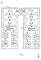
[0040]図1は、符号化及び復号システム10を示すブロック図である。図1に示されるように、システム10は、送信チャネル16によって接続されるエンコーダシステム12とデコーダシステム14とを含む。図1の例では、エンコーダシステム12は、第1のビデオ通信機器と関連付けられ、オーディオ発信源17と、ビデオ発信源18と、ビデオエンコーダ20と、オーディオエンコーダ22と、リアルタイムトランスポートプロトコル(RTP)/リアルタイムトランスポートプロトコル(RTCP)/ユーザデータグラムプロトコル(UDP)/インターネットプロトコル(IP)/ポイントツーポイントプロトコル(PPP)変換ユニット26と、無線リンクプロトコル(RLP)キュー28と、MACレイヤユニット30と、物理(PHY)レイヤユニット32とを含む。デコーダシステム14は、別のビデオ通信機器と関連付けられ、PHYレイヤユニット34と、MACレイヤユニット36と、RLPキュー38と、RTP/RTCP/UDP/IP/PPP変換ユニット40と、ビデオデコーダ42と、オーディオデコーダ44と、オーディオ出力機器46と、ビデオ出力機器48とを含む。
FIG. 1 is a block diagram illustrating an encoding and
[0041]以下でより詳細に説明されるように、エンコーダシステム12及び/又はデコーダシステム14は、ネットワーク条件に基づいて符号化レートを調整するために、本開示の技法を使用することができる。例えば、ビデオエンコーダ20は、少なくとも一部、ネットワーク帯域幅の関数として、ビデオ発信源符号化レートを制御することができる。具体的には、ビデオエンコーダ20は、ネットワークリンクレートの低下に応答して、ビデオデータ及び/又はオーディオデータの符号化レートを下げることができる。同様に、ビデオエンコーダ20は、ネットワークリンクレートの不十分な利用の指示に応答して、ビデオデータ及び/又はオーディオデータの符号化レートを上げることができる。
[0041] As described in more detail below,
[0042]システム10は、例えば、送信チャネル16を介したビデオ電話のために、双方向のビデオ及びオーディオの送信を提供することができる。従って、全般に相対応する符号化、復号及び変換ユニットが、チャネル16の反対側に設けられ得る。幾つかの実施形態では、エンコーダシステム12及びデコーダシステム14は、ビデオストリーミング、ビデオ電話又は両方に対応したワイヤレスモバイル端末などのビデオ通信機器内で具現化され得る。モバイル端末は、RTP、RTCP、UDP、IP又はPPPなどのパケット交換規格に従ってVTをサポートすることができる。
[0042] The
[0043]例えば、エンコーダシステム12において、RTP/RTCP/UDP/IP/PPP変換ユニット26は、ビデオエンコーダ20及びオーディオエンコーダ22から受信されたオーディオデータ及びビデオデータに、適切なRTP/RTCP/UDP/IP/PPPヘッダデータを追加し、データをRLPキュー28に配置する。例示的なビットストリームは、MACヘッダと、IPヘッダと、UDPヘッダと、RTCPヘッダと、ペイロードデータとを含み得る。幾つかの例では、RTP/RTCPはUDPの上で動作するが、UDPはIPの上で動作し、IPはPPPの上で動作する。幾つかの例では、本明細書で説明されるように、「RFC 3550: RTP: A Transport Protocol for Real−Time Applications」、H. Schulzrinne他、2003年7月、「RFC 5104: Codec Control Messages in the RTP Audio−Visual Provide with Feedback (AVPF)」、S.Wenger他、2008年2月(以後RFC 5104)及び/又はデータのリアルタイムのトランスポート若しくはほぼリアルタイムのトランスポートのための他の適用可能な規格などの、特定の規格に適合するRTP/RTCP/UDP/IP/PPP変換ユニット26。MACレイヤユニット30は、RLPキュー28の内容からMAC RLPパケットを生成する。PHYレイヤユニット32は、チャネル16を通じた送信のために、MAC RLPパケットをPHYレイヤパケットに変換する。
[0044]デコーダシステム14のPHYレイヤユニット34及びMACレイヤユニット36は、相互に動作する。PHYレイヤユニット34は、チャネル16から受信されたPHYレイヤパケットをMAC RLPパケットに変換する。MACレイヤユニット36は、MAC RLPパケットをRLPキュー38に配置する。RTP/RTCP/UDP/IP/PPP変換ユニット40は、RLPキュー38中のデータからヘッダ情報を奪い、ビデオデコーダ42及びオーディオデコーダ44への配信のためにそれぞれ、ビデオデータとオーディオデータとを再び組み立てる。
[0043] For example, in the
[0044] The
[0045]システム10は、符号分割多重接続(CDMA)、周波数分割多重接続(FDMA)、時分割多重接続(TDMA)又は直交周波数分割多重化(OFDM)若しくは別の適切なワイヤレス技法などの、1つ又は複数のワイヤレス通信技術をサポートするように設計され得る。上のワイヤレス通信技術は、様々な無線アクセス技術のいずれかに従って実現され得る。例えば、CDMAは、cdma2000又は広帯域CDMA(WCDMA(登録商標))規格に従って実現され得る。TDMAは、Global System for Mobile Communications(GSM(登録商標))規格に従って実現され得る。Universal Mobile Telecommunications System(UMTS)規格は、GSM又はWCDMA動作を可能にする。通常、VT用途では、システム10はhigh data rate(HDR)技術をサポートするように設計され得る。
[0045] The
[0046]ビデオエンコーダ20は、MPEG−4、High Efficiency Video Coding(HEVC)又は別のビデオコード化規格などの、あるビデオ圧縮方法に従って符号化されたビデオデータを生成する。他のビデオ圧縮方法は、国際電気通信連合(ITU)H.263、ITU H.264又はMPEG−2の方法を含む。オーディオエンコーダ22は、ビデオデータに付随するオーディオデータを符号化する。ビデオ発信源18は、1つ又は複数のビデオカメラ、1つ又は複数のビデオアーカイブ又はビデオカメラとビデオアーカイブの組合せなどの、撮像装置であり得る。
[0046]
[0047]オーディオデータは、適応マルチレートナローバンド(AMR−NB:adaptive multi-rate narrow band)又は他の技法などの、オーディオ圧縮方法に従って符号化され得る。オーディオ発信源17は、マイクロフォン又は音声合成器機器などの、オーディオキャプチャ機器であり得る。VT用途では、ビデオは参加者にVT会議を見えるようにし、オーディオはその参加者の話している声を聞こえるようにする。 [0047] Audio data may be encoded according to an audio compression method, such as adaptive multi-rate narrow band (AMR-NB) or other techniques. The audio source 17 can be an audio capture device, such as a microphone or a voice synthesizer device. In VT applications, the video allows the participant to see the VT conference and the audio allows the participant's speaking voice to be heard.
[0048]動作において、RTP/RTCP/UDP/IP/PPP変換ユニット26は、ビデオエンコーダ20及びオーディオエンコーダ22からビデオデータパケットとオーディオデータパケットとを取得する。前に言及されたように、RTP/RTCP/UDP/IP/PPP変換ユニット26は、適切なヘッダ情報をオーディオパケットに追加し、得られたデータをRLPキュー28内に挿入する。同様に、RTP/RTCP/UDP/IP/PPP変換ユニット26は、適切なヘッダ情報をビデオパケットに追加し、得られたデータをRLPキュー28内に挿入する。MACレイヤユニット30は、RLPキュー28からデータを取り出し、MACレイヤパケットを形成する。各MACレイヤパケットは、RTP/RTCP/UDP/IP/PPPヘッダ情報と、RLPキュー28内に含まれるオーディオパケットデータ又はビデオパケットデータとを搬送する。オーディオパケットは、ビデオパケットとは独立にRLPキュー28に挿入され得る。
In operation, RTP / RTCP / UDP / IP /
[0049]幾つかの場合、RLPキュー28の内容から生成されるMACレイヤパケットは、ヘッダ情報とビデオパケットデータとのみを搬送する。他の場合、MACレイヤパケットは、ヘッダ情報とオーディオパケットデータとのみを搬送する。多くの場合、MACレイヤパケットは、RLPキュー28の内容に応じて、ヘッダ情報と、オーディオパケットデータと、ビデオパケットデータとを搬送する。MACレイヤパケットは、無線リンクプロトコル(RLP)に従って構成されてよく、MAC RLPパケットと呼ばれ得る。PHYレイヤユニット32は、チャネル16にわたる送信のために、MAC RLPオーディオ−ビデオパケットをPHYレイヤパケットに変換する。
[0049] In some cases, the MAC layer packet generated from the contents of the
[0050]チャネル16は、PHYレイヤパケットをデコーダシステム14に搬送する。チャネル16は、エンコーダシステム12とデコーダシステム14との間の任意の物理的接続であり得る。例えば、チャネル16は、ローカルエリア又はワイドエリアの有線ネットワークなどの、有線接続であり得る。代替的に、本明細書で説明されるように、チャネル16は、セルラー接続、衛星接続又は光接続などの、ワイヤレス接続であり得る。チャネル条件は、有線チャネル及びワイヤレスチャネルの課題であり得るが、ワイヤレスチャネル16を通じて実行されるモバイルVT用途では特に関係があることがあり、ワイヤレスチャネル16においては、チャネル条件がフェージング又は混雑により悪化することがある。チャネル16は、チャネル条件に従って変動することがある、特定のネットワークリンクレート(例えば、特定の帯域幅)をサポートし得る。例えば、チャネル16は、チャネル条件に従って変化するスループットを有する逆方向リンク(RL)によって特徴付けられ得る。
[0050] Channel 16 carries PHY layer packets to
[0051]一般に、デコーダシステム14のPHYレイヤユニット34は、PHYレイヤパケットからMACレイヤパケットを特定し、内容をMAC RLPパケットへと再び組み立てる。MACレイヤユニット36は次いで、RLPキュー38内へ挿入するためのビデオパケットとオーディオパケットとを提供するために、MAC RLPパケットの内容を再び組み立てる。RTP/RTCP/UDP/IP/PPPユニット40は、付随するヘッダ情報を除去し、ビデオパケットをビデオデコーダ42に、オーディオパケットをオーディオデコーダ44に提供する。ビデオデコーダ42は、表示装置を駆動する際に使用するためのビデオデータのストリームを生成するために、ビデオデータフレームを復号する。オーディオデコーダ44は、例えばオーディオスピーカーを介してユーザに提示するためのオーディオ情報を生成するために、オーディオデータを復号する。
[0051] Generally, the
[0052]上で述べられたように、システム10は、例えば送信チャネル16を介したビデオ電話のために、双方向のビデオ及びオーディオの送信を提供することができる。幾つかの例では、チャネル16のネットワークリンクレートが変化するときに問題が発生することがあり、この変化は、Wi−Fi、セルラー又は他のネットワークリンクにおいて発生し得る。以下で図2に関してより詳細に説明されるように、レートの変動に対処し、場合によってはキューの管理を実行するために、1つ又は複数のバッファがネットワーク機器に含まれ得る。
[0052] As noted above, the
[0053]例えば、ある送信レート(例えば、ビデオエンコーダ20によって使用される符号化レート)を伴うVTフローは、リンクレートの突然の下落に遭遇することがあり、これはフローのボトルネックを生み得る。このリンクレートの下落に対するエンコーダシステム12における反応の遅延(例えば、これは、受信機の混雑制御フィードバックの遅延、送信機から受信機への戻り経路上での遅延、レート適合反応の遅延などによって引き起こされ得る)が原因で、送信レートはある時間の期間、リンクレートを大きく上回ったままであり得る。これは、ボトルネックリンクで増加したバッファレベルをもたらし、従って、エンコーダシステム12とデコーダシステム14との間のエンドツーエンドの遅延の増加(また更にはパケットの損失)をもたらすことがあり、これは、VTセッションの品質体験に悪影響を与えることがある。
[0053] For example, a VT flow with a certain transmission rate (eg, the coding rate used by video encoder 20) may encounter a sudden drop in link rate, which may create a flow bottleneck. . Response delays in
[0054]データがチャネル16を通じて送信される際のビットレートをエンコーダシステム12が下げた(例えば、送信レートを下げた)後で、蓄積された遅延がある時間残り得る。例えば、幾つかの事例では、蓄積された遅延が残る時間の長さは、送信レートと低減されたリンクレート(例えば、ボトルネックを引き起こすリンクレート)との間の差に依存し得る。送信レートの低下が小さすぎる場合、蓄積された遅延は比較的ゆっくり下がり、このことはデコーダシステム14におけるユーザ体験に影響を与え得る。保守的な送信レートの手法は、一貫して、推定されるリンクレートよりもはるかに低いレートで送信することである。しかしながら、この手法は、チャネル16におけるリンクの不十分な使用と、全体的なビデオ品質体験の低下とをもたらし得る。
[0054] After
[0055]本開示で説明される技法によれば、ビデオエンコーダ20は、チャネル16の条件に基づいて、ビデオ発信源18からビデオを符号化することができる。具体的には、ビデオエンコーダ20は、チャネル16における帯域幅の低下に基づいて、符号化レート(本明細書では送信レートとも呼ばれる)を下げることができる。符号化レートを下げることは、本明細書ではダウンスイッチングと呼ばれ得る。エンコーダシステム12は、チャネル16におけるリンクレートの大幅な下落が検出された後で、例えば、デコーダシステム14において生成された受信機側の混雑制御フィードバックメッセージがエンコーダシステム12において受信された後で、ビデオエンコーダ20において符号化されたデータの送信レートを一時的に下げることができる。
[0056]一例では、本開示の態様によれば、エンコーダシステム12は最初に、第1のビットレートでチャネル16を通じてデータを送信することができる。エンコーダシステム12は、第1のネットワークリンクレートから第2のネットワークリンクレートへのチャネル16におけるネットワークリンクレートの低下を特定することができる。幾つかの例では、エンコーダシステム12は、デコーダシステム14から受信された1つ又は複数の報告に基づいて、ネットワークリンクレートの低下を特定することができる。
[0055] In accordance with the techniques described in this disclosure,
[0056] In one example, according to aspects of this disclosure,
[0057]本開示の態様によれば、ネットワークリンクレートの低下を特定したことに応答して、エンコーダシステム12は、チャネル16を通じてデータを送信する際に用いるべき回復ビットレートを決定することができ、ここで回復ビットレートは第2のネットワークリンクレートより低い。エンコーダシステム12はまた、ネットワークリンクレートの低下の特定の時間と、ネットワークリンクレートの低下の推定される実際の時間との間の差を含む、バッファリング時間長を決定することができる。例えば、上で述べられたように、遅延を特定することと、ビデオエンコーダ20がデータを符号化する際のレートを調整することとに関連付けられる、何らかの反応時間があり得る。エンコーダシステム12は、ビデオエンコーダ20が符号化レートを特定してより低いレートへと調整するための時間を有するまで、初期の(より高い)ネットワークリンクにおいて、又はその近くで、ビデオエンコーダ20によって符号化されたデータをバッファリングすることができる。
[0057] According to aspects of the present disclosure, in response to identifying a decrease in network link rate,
[0058]エンコーダシステム12は、回復ビットレート及びバッファリング時間長に基づいて、回復ビットレートでデータを送信すべき回復レート時間長を決定することができる。エンコーダシステムは次いで、決定された回復レート時間長の間、回復ビットレートでデータを送信することができる。このようにして、本技法は、蓄積されたエンドツーエンドの遅延を比較的速く減らすことができ、エンドツーエンドの遅延が減らされた後で利用可能なリンクレートを使用することによって(例えば、より長い時間の期間、低減されたレートに送信レートを維持する場合よりも)、ユーザ体験の品質を守ることができる。例示を目的としてエンコーダシステム12に関して説明されたが、上で述べられた技法の幾つかは、追加で、又は代替的に、デコーダシステム14によって実行され得ることを理解されたい。
[0058] The
[0059]本開示の更に他の技法は、ネットワーク条件に基づいて、データが符号化されるレートをアップスイッチングする(例えば、上げる)ための技法を含む。例えば、「Discussion on Upswitch Principals」、SA4 MTSI SWG Conference Call No. 4 on End−to−End Video Rate Adaptation of E2EMTSI−S4、S4−AHM215、2014年6月24日(「AHM215」)の発表において、アップスイッチングについての幾つかの問題が特定された。「Report from SA4 MTSI SWG Conference Call No. 4 on End−to−End Video Rate Adaptation of E2EMTSI−S4 (2014年6月24日)」、Tdoc S4 (14)0768において記載されているように、アップスイッチングの原則について合意する前に、電話会議からの新たな着想について研究するために、さらなる議論が必要であると思われた。 [0059] Still other techniques of this disclosure include techniques for up-switching (eg, increasing) the rate at which data is encoded based on network conditions. For example, “Discussion on Upswitch Principles”, SA4 MTSI SWG Conference Call No. In the announcement of 4 on End-to-End Video Rate Adaptation of E2EMTSI-S4, S4-AHM215, June 24, 2014 ("AHM215"), several problems with up-switching were identified. “Report from SA4 MTSI SWG Conference Call No. 4 on End-to-End Video Rate Adaptation of E2EMTSI-S4 (June 24, 2014)”, as described in Tdoc S4 (14) 0768 Prior to agreeing on the principles, it was thought that further discussion was needed to study new ideas from the conference call.
[0060]一般に、AHM215において発表されたモデルは、ランプアッププロービングモデルに依存し、これには、プローブがチャネル条件に一致していないときに、プロービングがシステムに遅延をもたらし得るという欠点があり得る。よりロバストなモデルは、デコーダシステム14などの受信機が、システムに余剰の能力があり得るかどうかを決定するためにチャネル16の状態を受動的に測定することを可能にすることである。これに基づいて、デコーダシステム14は、システムの持続可能なレートのより正確な推定を行うことができる。
[0060] In general, the model presented at AHM 215 relies on a ramp-up probing model, which can have the disadvantage that probing can introduce delay into the system when the probe does not match the channel conditions. . A more robust model is to allow a receiver, such as the
[0061]AHM215において発表されたモデルはまた、2段階の手法を提案しており、この手法では、エンコーダシステム12はまず、さらなる能力があり得るかどうかを確認するためにチャネルをプローブする。プロービング段階が成功すると、ビデオエンコーダ20は、「ランプアップ段階(ramp-up phase)」の間にレートをより積極的に上げることができる。そのようなモデルは、比較的大量の混雑をシステムにもたらす可能性があり、それは、データレートの微増を伴う成功したプローブは、システムがその後非常に大幅な増加を処理できることを暗示し得ないためである。実際には、ビデオエンコーダ20のレートをシステムの能力と一致するように増加するとき、よりロバストな手法は、まずレートを比較的大きく増加して、その後、チャネル16によってサポートされる持続可能なレートへとレートが収束するにつれてよりステップを小さくすることである。
[0061] The model presented at AHM 215 also proposes a two-stage approach, in which
[0062]上で説明された方式で持続可能なレートに収束する、潜在的によりロバストな手法に従うには、適合を駆動するエンティティ(例えば、送信機(エンコーダシステム12)又は受信機(デコーダシステム14))は、システムの持続可能なレートの推定値を有しなければならない。送信機は、エンドツーエンドのチャネル条件を検出するためにRTCP受信機報告に依存することがあり、全体のスループットを計算することができるが、それでも、RTCP報告によりいくらかの測定遅延がある。受信機は、全体のスループットと、予定される再生に対してデコーダシステム14におけるパケットの到着が遅すぎるとはされない、許容され得る追加の遅延の量との両方を、計算することができる。従って、受信機において計算される関連する尺度が送信機に直接送信される場合、受信機により駆動される適合モデルは、実現され、よりロバストであることがあり、最小限の適合の実行を決定する際に使用されるべきである。
[0062] To follow a potentially more robust approach to converge to a sustainable rate in the manner described above, the entity driving the adaptation (eg, transmitter (encoder system 12) or receiver (decoder system 14)). )) Must have an estimate of the sustainable rate of the system. The transmitter may rely on RTCP receiver reports to detect end-to-end channel conditions and can calculate the overall throughput, but there is still some measurement delay due to RTCP reports. The receiver can calculate both the overall throughput and the amount of additional delay that can be tolerated that the arrival of packets at the
[0063]本開示の態様によれば、デコーダシステム14は、チャネル16において帯域幅が十分に利用されていないと決定すると、受信機により駆動されるレートアップスイッチング技法を実施することができる。例えば、本開示の態様によれば、デコーダシステム14は、ビデオエンコーダ20に符号化レートを上げるように促すデータをエンコーダシステム12に提供することができる。
[0063] According to aspects of this disclosure, if the
[0064]幾つかの例では、本開示の態様によれば、デコーダシステム14は、データがデコーダシステム14によって受信される時間と受信されたデータが再生されるように予定される時間との間の差に基づいて、許容可能超過遅延パラメータを決定することができる。許容可能超過遅延パラメータは、ユーザ体験が影響を受けない、例えば、適切な時間に復号され、再生されるのにデータの到着が遅すぎない、チャネル16によって対応可能な遅延の量を示すことができる。デコーダシステム14はまた、決定された許容可能超過遅延パラメータに基づいて、データがエンコーダシステム12からデコーダシステム14に送信される際に用いるべきビットレートを増加するための、送信機ビットレートの増加を決定することができる。デコーダシステム14はまた、送信機ビットレートの増加の指示をエンコーダシステム12に送信することができる。
[0064] In some examples, according to aspects of the present disclosure, the
[0065]このように、デコーダシステム14は、ネットワークに混雑をもたらすことなくユーザ体験を改善するために、制御された方式でビデオフローの平均ビットレートを制御することができる。この技法は、パケット損失をもたらし得るエンドツーエンドの遅延を大きく増加することを避け得る。
[0065] Thus, the
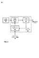
[0066]図2は、本開示の技法によるビデオ発信源レート適合を実施し得るエンコーダシステム12を示すブロック図である。図2に示されるように、ビデオエンコーダ20は、ビデオ符号化エンジン50と、ビデオバッファ52と、ビデオレートコントローラ54とを含む。ビデオエンコーダ20はまた、ネットワークリンクレート情報56を受信し、これはデコーダシステム14によって準備され得る(以下でより詳細に説明される)。
[0066] FIG. 2 is a block diagram illustrating an
[0067]ビデオ符号化エンジン50は、ビデオ発信源18からビデオデータを取得し、ビデオレートコントローラ54によって制御されるレートでビデオデータを符号化する。ビデオ符号化エンジン50は次いで、符号化されたビデオをビデオバッファ52に収納する。ビデオレートコントローラ54は、ビデオバッファ52の充満度を監視し、充満度に少なくとも一部基づいて、ビデオ符号化エンジン50によって適用されるビデオ符号化レートを制御することができる。加えて、以下でより詳細に説明されるように、ビデオレートコントローラ54は、ネットワークリンクレート情報56及び/又はチャネル16(図1)の条件と関連付けられる他のデータに基づいて、レートを制御することができる。
[0067]
[0068]幾つかの例では、ビデオエンコーダ20は、全般にコーデックとは独立なビデオ発信源レート制御方式を提供することができる。例えば、ビデオエンコーダ20は、HEVC、MPEG4、ITU H.263、又はITU H.264に従って、ビデオ符号化のために適合され得る。加えて、ビデオエンコーダ20は、DSP又は組込み型論理コア内での実装の影響を受けやすいことがある。幾つかの実施形態では、ビデオエンコーダ20(例えば、ビデオエンコーダ20のビデオレートコントローラ54)は、モデルベースのレート制御を適用することができ、例えば、ビデオブロックレート制御をrho領域において適用することができる。例えば、フレームビット計画が特定のビデオフレームに対して確立されると、フレームビット計画は、フレーム内のビデオブロック、例えばコーディングユニット(CU)及び/又はマクロブロック(MB)の間で、rho領域レート制御を使用して割り振られ得る。個々のMBのためのrho領域値は次いで、量子化パラメータ(QP)値にマッピングされ得る。
[0068] In some examples,
[0069]本開示の態様によれば、ビデオレートコントローラ54は、ネットワーク条件に基づいてレートダウンスイッチングを実行することができる。例えば、ビデオ符号化エンジン50は最初に、チャネル16(図1)などのトランスポート媒体を通じた送信のために、第1のビットレートでデータを符号化することができる。ビデオレートコントローラ54は、第1のネットワークリンクレートから第2のネットワークリンクレートへのネットワークリンクレートの低下を特定することができる。幾つかの例では、ビデオレートコントローラ54は、ビデオエンコーダ20において、ネットワークリンクレートの低下をフィードバックから特定することができる。他の例では、ビデオレートコントローラ54は、ネットワークリンクレート情報56に基づいて、ネットワークリンクレートの低下を特定することができる。
[0069] According to aspects of this disclosure, video rate controller 54 may perform rate down switching based on network conditions. For example,
[0070]ネットワークリンクレートの低下を特定したことに応答して、ビデオレートコントローラ54は、第2の(低減された)ネットワークリンクレートより低い、ビデオエンコーダ20のための回復ビットレートを決定することができる。回復レートは、ネットワークリンクレートの低下の実際の時間とネットワークリンクレートの低下の同定との間にバッファリングされたデータ量を減らすために使用され得る。そのようなバッファリングされたデータを減らすことは、ユーザ体験が受信機機器において影響を受けないように支援する。従って、ビデオレートコントローラ54は、ビデオエンコーダ20においてバッファリングされたデータの量を少なくするために低減されたネットワークリンクレートをアンダーシュートする、ビデオエンコーダ20において使用するための回復ビットレートを決定することができる。
[0070] In response to identifying the decrease in the network link rate, the video rate controller 54 determines a recovery bit rate for the
[0071]本開示の態様によれば、ビデオレートコントローラ54は、アンダーシュート係数に基づいて回復レートを決定することができる。ビデオレートコントローラ54は、第1のネットワークリンクレートと低減されたネットワークリンクレートとの間の差に基づいてアンダーシュート係数を決定することができる。即ち、ビデオレートコントローラ54は、ネットワークリンクレートの低下の大きさに基づいて変化する大きさを有する、アンダーシュート係数を決定することができる。従って、ネットワークリンクレートの低下が比較的大きい場合、ビデオレートコントローラ54は、比較的大きいアンダーシュート係数を決定し得る。同様に、ネットワークリンクレートの低下が比較的小さい場合、ビデオレートコントローラ54は、比較的小さいアンダーシュート係数を決定し得る。 [0071] According to aspects of this disclosure, video rate controller 54 may determine a recovery rate based on an undershoot factor. Video rate controller 54 may determine an undershoot factor based on the difference between the first network link rate and the reduced network link rate. That is, the video rate controller 54 can determine an undershoot factor that has a magnitude that varies based on the magnitude of the decrease in the network link rate. Thus, if the network link rate decrease is relatively large, video rate controller 54 may determine a relatively large undershoot factor. Similarly, if the network link rate decrease is relatively small, video rate controller 54 may determine a relatively small undershoot factor.
[0072]幾つかの例では、ビデオレートコントローラ54は、回復レートを決定するために低減されたネットワークリンクレートに適用され得るアンダーシュート係数を決定することができる。例えば、ビデオレートコントローラ54は、小数のアンダーシュート係数を決定することができ、小数のアンダーシュート係数を低減されたネットワークリンクレートに適用して回復レートを決定することができる。一例では、ビデオレートコントローラ54は、ネットワークリンクレートの低下の大きさの、第1のネットワークリンクレートに対する比に基づいてアンダーシュート係数を決定することができる。 [0072] In some examples, video rate controller 54 may determine an undershoot factor that may be applied to the reduced network link rate to determine a recovery rate. For example, video rate controller 54 can determine a small number of undershoot coefficients and can apply the small number of undershoot coefficients to the reduced network link rate to determine the recovery rate. In one example, the video rate controller 54 can determine the undershoot factor based on a ratio of the magnitude of the decrease in the network link rate to the first network link rate.
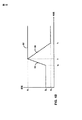
[0073]本開示の態様によれば、ビデオレートコントローラ54は、ネットワークリンクレートの低下の特定の時間とネットワークリンクレートの低下の推定される実際の時間との間で、どれだけのデータがビデオエンコーダ20においてバッファリングされるか(又は、より一般的には、ビデオエンコーダ20を含む送信機機器においてどれだけのデータがバッファリングされるか)に基づいて、回復レートをどれだけ長く維持するかを決定することができる。送信機機器においてデータをバッファリングすることと関連付けられる時間は、バッファリング時間長(又はバッファリング時間期間)と本明細書では呼ばれ得るが、回復レートを維持すべき時間長は、回復レート時間長(又は低減レート時間期間)と本明細書では呼ばれ得る。幾つかの事例では、回復レート時間長はまた、アンダーシュート時間長又は期間と呼ばれることがあり、それは、回復レート時間長の間にデータが符号化されるレートがネットワークリンクレートより低いからである。 [0073] In accordance with aspects of this disclosure, video rate controller 54 determines how much data is video between a particular time of network link rate decrease and an estimated actual time of network link rate decrease. How long to maintain the recovery rate based on what is buffered at the encoder 20 (or more generally how much data is buffered at the transmitter equipment including the video encoder 20) Can be determined. Although the time associated with buffering data at the transmitter equipment may be referred to herein as the buffering time length (or buffering time period), the time length to maintain the recovery rate is the recovery rate time It may be referred to herein as a long (or reduced rate time period). In some cases, the recovery rate duration may also be referred to as the undershoot duration or duration because the rate at which data is encoded during the recovery rate duration is lower than the network link rate. .
[0074]以下で図5に関してより詳細に説明されるように、ビデオレートコントローラ54は、様々な方法でバッファリング時間長を決定することができる。例えば、ビデオレートコントローラ54は、ビデオエンコーダ20を組み込む送信機機器と受信機機器との間のラウンドトリップ時間(RTT)、ダウンリンク遅延(例えば、受信機から送信機への遅延)、レート適合反応の遅延に関するデータ、混雑制御の反応遅延(例えば、リンクレートの推定)、メッセージ生成遅延(RTCPパケット)などの、ネットワークリンクレート情報56からバッファリング時間長を推定することによって、バッファリング時間長を決定することができる。ネットワークリンクレート情報56は、ビデオエンコーダ20において利用可能であることがあり、又は受信機機器によってビデオエンコーダ20に信号伝達され得る。
[0074] As described in more detail below with respect to FIG. 5, video rate controller 54 may determine the buffering length in various ways. For example, the video rate controller 54 may include a round trip time (RTT) between a transmitter device and a receiver device that incorporates the
[0075]本開示の態様によれば、ビデオレートコントローラ54は、回復レートの大きさに基づいて、及びバッファリング時間長に基づいて、回復レート時間長を決定することができる。幾つかの例では、ビデオレートコントローラ54は、(例えば、回復レートによって示されるような)ネットワークリンクレートの低下の大きさと、(例えば、バッファリング時間長によって示されるような)ネットワークリンクレートの低下に反応することと関連付けられる時間の量とに比例する、バッファリング時間長を決定することができる。即ち、ネットワークリンクレートの低下が比較的大きい場合、及び/又は、ネットワークリンクレートの低下に反応するのに必要な時間が比較的長い場合、ビデオレートコントローラ54は、それに比例して長い回復レート時間長を決定することができる。同様に、ネットワークリンクレートの低下が比較的小さい場合、及び/又は、ネットワークリンクレートの低下に反応するのに必要な時間が比較的短い場合、ビデオレートコントローラ54は、それに比例して短い回復レート時間長を決定することができる。 [0075] According to aspects of this disclosure, video rate controller 54 may determine a recovery rate time length based on the magnitude of the recovery rate and based on the buffering time length. In some examples, the video rate controller 54 may determine the magnitude of the network link rate decrease (eg, as indicated by the recovery rate) and the network link rate decrease (eg, as indicated by the buffering time length). A buffering time length that is proportional to the amount of time associated with reacting to can be determined. That is, if the decrease in network link rate is relatively large and / or if the time required to react to the decrease in network link rate is relatively long, video rate controller 54 may proportionally increase the recovery rate time. The length can be determined. Similarly, if the decrease in network link rate is relatively small and / or if the time required to react to the decrease in network link rate is relatively short, video rate controller 54 may have a proportionally shorter recovery rate. The time length can be determined.
[0076]本開示の他の態様によれば、ビデオレートコントローラ54は、加えて、又は代替的に、ネットワーク条件に基づいてレートのアップスイッチングを実行することができる。例えば、ビデオレートコントローラ54は、デコーダシステム14(図1)を含む機器などの受信機機器からネットワークリンクレート情報56を受信することができる。ビデオレートコントローラ54は、データを符号化するためにビデオ符号化エンジン50によって使用されている送信レート(例えば、符号化レート)をアップスイッチングするために、受信されたネットワークリンクレート情報56を使用することができる。
[0076] According to other aspects of the present disclosure, video rate controller 54 may additionally or alternatively perform rate up-switching based on network conditions. For example, video rate controller 54 may receive network link rate information 56 from a receiver device, such as a device that includes decoder system 14 (FIG. 1). Video rate controller 54 uses received network link rate information 56 to upswitch the transmission rate (eg, encoding rate) being used by
[0077]幾つかの例では、受信されたネットワークリンクレート情報56は、ビデオ符号化エンジン50によって実施されている特定の要求された送信レート(例えば、符号化レート)を含み得る。他の例では、受信されたネットワークリンクレート情報56は、現在の送信レート(例えば、送信レートステップ)に追加されるべき、レートステップの増加を含み得る。いずれの場合でも、図3に関して以下でより詳細に説明されるように、受信されたネットワークリンクレート情報56は、パケットが再生されるように予定される前に受信機機器においてパケットが受信されたことを示す超過遅延パラメータに基づき得る。そのような事例において、ビデオレートコントローラ54は、パケットの到着時間が受信機機器におけるパケットの予定された再生時間とより厳密に一致するまで、ビデオ符号化エンジン50によって使用される送信レートを上げることができる。
[0077] In some examples, the received network link rate information 56 may include a particular requested transmission rate (eg, encoding rate) being implemented by the
[0078]図2の技法は図2の特定のコンポーネント(例えば、ビデオレートコントローラ54など)によって行われるものとして説明されるが、そのような技法は、追加で、又は代替的に、ビデオ電話機器の1つ又は複数の他のコンポーネントによって実行され得ることを理解されたい。例として、MTSI機器は、レート適合及び/又は混雑制御を実行するために、上で説明された幾つかの技法を行うことができる。この例では、MTSI機器は次いで、ビデオエンコーダにおいて適切なレート制御を実施するためにデータをビデオレートコントローラ54に提供することができる。 [0078] Although the techniques of FIG. 2 are described as being performed by certain components of FIG. 2 (eg, video rate controller 54, etc.), such techniques may additionally or alternatively be video telephony equipment. It should be understood that it may be performed by one or more other components. As an example, an MTSI device may perform some of the techniques described above to perform rate adaptation and / or congestion control. In this example, the MTSI device can then provide data to the video rate controller 54 to perform appropriate rate control at the video encoder.
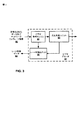
[0079]図3は、本開示の技法によるビデオ発信源レート適合を実施し得るビデオデコーダシステム14を示すブロック図である。図3に示されるように、ビデオデコーダ42は、符号化されたデータとネットワークリンクレート情報60とを受信し、ビデオ復号エンジン62と、再生決定ユニット64と、レート制御データ68を生成するレート制御ユニット66とを含む。
[0079] FIG. 3 is a block diagram illustrating a
[0080]ビデオ復号エンジン62は、符号化されたデータとネットワークリンクレート情報60とを受信し、ビデオデータを復号する。幾つかの例では、ビデオ復号エンジン62は、1つ又は複数のビデオコード化規格に適合し得る。上で述べられたように、例示的なビデオコード化規格は、HEVC、MPEG4、ITU H.263、又はITU H.264を含む。
[0080] The video decoding engine 62 receives the encoded data and the network
[0081]ビデオデータが受信されるレートは、ビデオエンコーダ20(図2)のビデオレートコントローラ54によって制御され得る。本開示の態様によれば、レート制御ユニット66は、符号化レートを調整する際に使用するためのレート制御データ68を準備して、ビデオエンコーダ20に送信することができる。幾つかの例では、レート制御データ68は、送信機機器においてダウンスイッチングを実行するためのデータを含み得る。他の例では、加えて、又は代替的に、レート制御データ68は、送信機機器においてアップスイッチングを実行するためのデータを含み得る。レート制御ユニット66は、送信機機器が適切なビットレートを決定することを可能にするデータを準備することができ、又は、送信機機器から特定のビットレートを要求することができる。
[0081] The rate at which video data is received may be controlled by the video rate controller 54 of the video encoder 20 (FIG. 2). According to aspects of this disclosure,
[0082]ダウンスイッチングのためのデータを準備することに関して、本開示の態様によれば、レート制御ユニット66は、図2に関して上で説明されたのと同様の方式で、回復レート、バッファリング時間長及び/又は回復レート時間長を決定することができる。他の例では、レート制御ユニット66は、回復レート、バッファリング時間長及び/又は回復レート時間長を決定するために送信機機器(エンコーダシステム12など)によって使用され得る、データを生成し、及び/又はメッセージを送信することができる。
[0082] With respect to preparing data for down-switching, according to aspects of this disclosure,
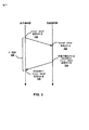
[0083]一例では、レート制御ユニット66は、ネットワークリンクレートの低下を示すために、順方向チャネルの推定される最大ビットレートを伴う、送信機機器へのRTCP一時最大メディアストリームビットレート要求(TMMBR:Temporary Maximum Media Stream Bit Rate Request)メッセージを生成することができる。一般に、上で述べられたRFC5104に記載されるように、受信機、変換器又は混合器は、メディアストリームの最大ビットレートを与えられた値に、又はそれ未満に制限するように送信機に要求するために、TMMBR(「timber」と呼ばれる)を使用することができる。一時最大メディアストリームビットレート通知(TMMBN)は、メディア送信機を更に制約しないであろうTMMBRを参加者が抑制するのを助けるためにメディア送信機が受信した、TMMBRで定義された制限の最も限定的なサブセットの、メディア送信機の現在の見方を含んでいる。
[0083] In one example,
[0084]本開示の態様によれば、第1のレートから第2のより低いレートへの順方向チャネルの推定される最大ビットレートの変化は、ネットワークリンクレートの低下を示す。幾つかの例では、レート制御ユニット66は、混雑が検出されると直ちに、又はほぼ直ちに、TMMBRを送信することができる(例えば、TMMBRメッセージを生成することと関連付けられるメッセージ生成遅延があり得る)。TMMBRメッセージが例示を目的に説明されるが、遅延/混雑を示す様々な他のメッセージが使用され得ることを理解されたい。
[0084] According to aspects of this disclosure, a change in the estimated maximum bit rate of the forward channel from a first rate to a second lower rate indicates a decrease in network link rate. In some examples,
[0085]本明細書で説明されるバッファリング時間長を推定することで送信機機器を支援するために、レート制御ユニット66は、RTCP受信機報告(RR:receiver report)メッセージを生成して送信することもできる。例えば、上で述べられたRFC3550において記載されるように、幾つかのRTCPパケットのタイプが、様々な制御情報を搬送するために使用され得る。送信機報告(SR:sender report)が、動作している送信機である参加者からの送信と受信の統計のために使用され得る。RRは、動作している送信機ではない参加者からの受信統計のために、及び、32個以上の発信源についての動作している送信機の報告のためのSRと組み合わせて、使用され得る。
[0085] To assist the transmitter equipment by estimating the buffering time length described herein, the
[0086]本開示の態様によれば、レート制御ユニット66は、TMMBRメッセージの後で、例えばTMMBRメッセージの直後に、又はほぼ直後に、RRメッセージを生成して送信することができる。この例では、送信機機器は、TMMBRメッセージとRRメッセージとを受信することができ、RRに含まれる最後のSRのタイムスタンプ(LSRデータ)によってRRにおいて参照されるSRの送信の時間と、送信機機器によってRRが受信される時間との時間差として、バッファリング時間長の上限を決定することができる。言い換えると、レート制御ユニット66は、ビットレート制限のための要求を示す第1のデータ(例えば、TMMBRメッセージ)と、メッセージが生成された時間を示す第2のデータ(例えば、LSRデータ)とを送信することができる。LSRデータは、発信源から最新のRTCP SRパケットの一部として受信された、64ビットのネットワーク時間プロトコル(NTP)タイムスタンプのうちの中間の32ビットを含み得る。SRがまだ受信されていない場合、LSRタイムスタンプフィールドは0に設定され得る。送信機機器は、上で述べられたデータを受信することができ、そのデータを使用してバッファリング時間長を決定することができ、バッファリング時間長はダウンスイッチングの間に使用され得る。
[0086] According to aspects of this disclosure,
[0087]別の例では、2つの別の連続するメッセージ(例えば、TMMBR及びRTCP RR)を送信するのではなく、レート制御ユニット66は、TMMBRデータとRTCP RRデータとを単一のRTCPメッセージへとグループ化することができ、単一のメッセージを送信機機器に送信することができる。最低でも、レート制御ユニット66はLSRデータを送信することができ、これは送信機機器がバッファリング時間長を推定することを可能にする。この例では、2つの別のメッセージを送信する場合よりも、メッセージサイズが減らされ得る。
[0087] In another example, rather than sending two separate consecutive messages (eg, TMMBR and RTCP RR),
[0088]幾つかの例では、レート制御ユニット66は、送信機機器に送信すべき最後の受信されたRTCP SRのLSRを、同じLSRを有するRTCP RRを以前に送信していたとしても、使用することができる。レート制御ユニット66がRRをまだ送信していない場合、レート制御ユニット66は、完全なRRをTMMBRと組み合わせることができる。他の例では、メッセージサイズを減らすために、レート制御ユニット66は、LSRデータをTMMBRと一緒に送信することだけが可能であり、送信機機器は、RTTを決定するためにTMMBRを受信して使用することができる。更に別の例では、レート制御ユニット66がすでにRRを送信していた場合、送信機機器は、最後の受信されたRRを受信した時間と新たなRR(例えば、混雑が検出された後でレート制御ユニット66によって送信されたRR)を受信した時間との間の時間差として、バッファリング時間長をより正確に計算することができる。
[0088] In some examples, the
[0089]レート制御ユニット66はまた、回復レート時間長を決定し、及び/又は、回復レート時間長を決定するためにデータを生成して送信機機器に送信することができる。例えば、上で説明された技法の代わりに、又はそれに加えて、レート制御ユニット66(又は送信機機器)は、回復レート時間長をいつ終了すべきか決定するために、RTCP RR到着間ジッタ(inter-arrival jitter data)を監視することができる。一般に、到着間ジッタデータは、タイムスタンプ単位で測定され、符号なしの整数として表される、RTPデータパケットの到着間の時間の統計的な分散の推定を与え得る。到着間ジッタJは、パケットのペアのための送信機と比較された、受信機におけるパケット間隔の差分Dの標準偏差(平滑化された絶対値)として定義され得る。下の式(1)に示されるように、これは、2つのパケットの「相対送信時間」の差分と等価であり、相対送信時間は、パケットのRTPタイムスタンプと、同じ単位で測定された到着の時間における受信機の時計との間の差分である。SiがパケットiからのRTPタイムスタンプであり、Riがパケットiに対するRTPタイムスタンプ単位の到着の時間である場合、2つのパケットi及びjに対して、Dは次のように表され得る。
[0089]
D(i,j) = (Rj - Ri) - (Sj - Si) = (Rj - Sj) - (Ri - Si) (1)
[0090]本開示の態様によれば、到着間ジッタが0又は閾値未満になる場合、送信機機器は、レート低減を終了することができる(例えば、送信機機器は、低減されたレートからほぼネットワークリンクレートへと送信レートを上げることができる)。閾値は、定数であってよく、又はネットワーク条件の変化に適応してよい。幾つかの例では、送信機機器は、到着間ジッタが最小の時間の期間の間0又は閾値未満に維持されると、レート低減を終了することができる。幾つかの事例では、レート制御ユニット66がRTCP SRとRRとを頻繁に信号伝達するほど、送信機機器は到着間ジッタをより正確に監視することができる。
D (i, j) = (Rj-Ri)-(Sj-Si) = (Rj-Sj)-(Ri-Si) (1)
[0090] According to aspects of this disclosure, if the inter-arrival jitter is zero or less than a threshold, the transmitter equipment may terminate the rate reduction (eg, the transmitter equipment may be approximately out of the reduced rate. You can increase the transmission rate to the network link rate). The threshold may be a constant or may adapt to changes in network conditions. In some examples, the transmitter equipment may terminate rate reduction once the inter-arrival jitter is maintained at 0 or below a threshold for a minimum time period. In some cases, the more frequently the
[0091]更に別の例では、送信機機器(エンコーダシステム12など)は遅延(例えば、RTT)を監視することができ、送信機は、遅延が十分に低減されるまで、送信レートを低減されたレートに維持することができる。例えば、送信機機器は、バッファに記憶されているデータの量が閾値レベルを下回るまで、送信レートを低減されたレートに維持することができる。 [0091] In yet another example, a transmitter device (such as encoder system 12) can monitor a delay (eg, RTT) and the transmitter is reduced in transmission rate until the delay is sufficiently reduced. Can be maintained at the same rate. For example, the transmitter device can maintain the transmission rate at a reduced rate until the amount of data stored in the buffer is below a threshold level.
[0092]本開示の他の技法によれば、再生決定ユニット64は、受信されたビデオパケットを検査し、受信されたデータが予定された再生に対して早く到着しているか、時間通りに到着しているか、又は遅く到着しているかを決定することができる。予定された再生タイミングは、符号化されたデータを用いて示され得る。パケットが遅く到着している場合(例えば、パケットが受信/検査されるより前に再生時間がある場合)、レート制御ユニット66は、送信ビットレートを下げるように送信機機器に要求することができる。幾つかの例では、レート制御ユニット66は、選択されたレートを用いてTMMBRメッセージを送信することができる。
[0092] According to other techniques of this disclosure, playback decision unit 64 examines the received video packet and the received data arrives early or on time for the scheduled playback. You can decide whether you are arriving late or arriving late. Scheduled playback timing can be indicated using encoded data. If the packet is arriving late (eg, if there is a playback time before the packet is received / inspected), the
[0093]幾つかの態様によれば、レート制御ユニット66は、除去される必要のある超過遅延の量を決定し、レート制御ユニット66によって測定されるような到着したビデオのデータレートとこの超過遅延パラメータを乗算することによって、残りのデータ(例えば、送信機機器においてバッファリングされたデータ)の量を推定することができる。言い換えると、レート制御ユニット66は、データが受信/検査される時間とデータを用いて示される再生時間との間の差に基づいて、遅延を決定することができる。レート制御ユニット66は次いで、データが受信されているビットレートとこの遅延時間を乗算して、送信機によってバッファリングされているデータの量を決定することができる。
[0093] According to some aspects,
[0094]幾つかの例では、レート制御ユニット66は、システムがチャネルの混雑を解消することを可能にするために、ビデオデコーダ42と送信機機器との間のトランスポート経路の持続可能なレート(例えば、ネットワークリンクの使用可能な帯域幅)より低い初期レートを(例えば、TMMBRメッセージにおいて)要求することができる。ある例では、レート制御ユニット66は、システムが(変数T_decongestによって示される)固定された量の時間でチャネルの混雑を解消することを可能にするのに十分低い初期レートを選択することができる。変数R_sustainがチャネルの持続可能なレートに等しい場合、変数ΔDelayは除去される必要のある遅延の量に等しく、そして、レート制御ユニット66は最初に、以下の式(2)に従ってビットレートRでデータを符号化するように送信機機器に要求することができる。
[0094] In some examples,
R = R_sustain (1- ΔDelay/T_decongest) (2)
要求されたビットレートを含むメッセージ(例えば、TMMBRメッセージ)を送信した後で、レート制御ユニット66は、混雑解消時間(T_decongest)が経過するのを待つことができる。レート制御ユニット66は次いで、ネットワークリンクによって持続可能なレート(R_sustain)で、別の要求されたビットレート(例えば、追加のTMMBRメッセージ)を送信することができ、こうして、混雑解消期間を終了する。
R = R_sustain (1- ΔDelay / T_decongest) (2)
After sending a message (eg, a TMMBR message) that includes the requested bit rate, the
[0095]別の例では、レート制御ユニット66、レートを上げるために別のメッセージ(例えば、追加のTMMBRメッセージ)を送信しなくてよい。この例では、レート制御ユニット66は、許容可能な遅延の量(例えば、所定の閾値より少ない遅延)を測定するのを単に開始することができる。遅延の量が必要とされるよりも小さい(例えば、適切に予定された再生のために必要とされるよりも早くパケットが到着している)とレート制御ユニット66が決定する場合、レート制御ユニット66は、送信機機器の符号化レートを増加する(increase)/上昇する(ramp up)するために、別のメッセージ(例えば、別のTMMBRメッセージ)を送信することができる。
[0095] In another example,
[0096]アップスイッチングに関して、送信機機器と受信機機器との間のチャネル(エンコーダシステム12とデコーダシステム14との間のチャネル16(図1)など)が送信機機器によって十分に利用されていないとき、ビデオデコーダ42へのビデオパケットの配信は、そのようなビデオパケットが実際に再生される(例えば、データを用いて示される再生時間の前に受信される)ことが必要になる前に発生する可能性が高い。そのような事例では、送信機レートは増加されてよく、幾つかの追加の遅延が、ユーザ体験に悪影響を与えることなくシステムにもたらされ得る。
[0096] For up-switching, the channel between the transmitter device and the receiver device (such as channel 16 (FIG. 1) between the
[0097]送信経路にもたらされ得る超過ビットは、チャネル帯域幅がレート制御ユニット66において測定される平均受信レートに等しい事例(例えば、利用可能な予備のチャネル帯域幅がない最悪の場合)では、以下の式(3)に従って計算され得る。 [0097] The excess bits that can be introduced into the transmission path are cases where the channel bandwidth is equal to the average receive rate measured in rate control unit 66 (eg, in the worst case where there is no spare channel bandwidth available). Can be calculated according to the following equation (3).
excess_bits = rate_increase_step * (RTT + receiver_detection_delay) (3)
ここで、excess_bitsはシステムにもたらされる追加のビットを示し、rate_increase_stepは符号化レートの増加を示し、RTTはラウンドトリップ時間を示し、receiver_detection_delayは受信機によってシステムの遅延を検出することと関連付けられる遅延を示す(これは、本明細書で説明される技法のいずれかに従って決定され得る)。
excess_bits = rate_increase_step * (RTT + receiver_detection_delay) (3)
Where excess_bits indicates the additional bits introduced into the system, rate_increase_step indicates the coding rate increase, RTT indicates the round trip time, receiver_detection_delay indicates the delay associated with detecting the system delay by the receiver. (This can be determined according to any of the techniques described herein).
[0098]幾つかの例では、レート制御ユニット66は、以下の式(4)に従って、もたらされた超過ビット(excess_bits)が原因の対応する最悪の場合の超過遅延(excess_delay)を決定することができる。
[0098] In some examples,
excess_delay = rate_increase_step * (RTT + receiver_detection_delay) / avg_receiving_rate
(4)
ここで、excess_delayは送信機機器においてもたらされる遅延の量を示し、rate_increase_stepは符号化レートの増加を示し、RTTは送信機機器とビデオデコーダ42との間のラウンドトリップ時間を示し、receiver_detection_delayはレート制御ユニット66によってシステムの遅延を検出することと関連付けられる遅延を示し、avg_receiving_rateはデータがビデオデコーダ42において受信されているレートを示す。
excess_delay = rate_increase_step * (RTT + receiver_detection_delay) / avg_receiving_rate
(Four)
Where excess_delay indicates the amount of delay introduced in the transmitter device, rate_increase_step indicates the increase in coding rate, RTT indicates the round trip time between the transmitter device and
[0099]従って、幾つかの例では、本開示の態様によれば、ビデオデコーダ42のレート制御ユニット66は、特定のレート増加と関連付けられる超過ビットの数(例えば、excess_bits)と、超過ビットの混入と関連付けられる遅延(例えば、excess_delay)とを決定することができる。
[0099] Thus, in some examples, according to aspects of this disclosure,
[0100]レート制御ユニット66は、許容可能超過遅延パラメータに基づいて、レート増加の量を計算することができる。例えば、レート制御ユニット66は、下の式(5)に従って、混雑及び/又は遅延をシステムにもたらすことなく送信レートがどれだけ送信機機器によって上げられ得るかを決定することができる。
[0100]
rate_increase_step = allowable_excess_delay * avg_receiving_rate / (RTT +
receiver_detection_delay) (5)
ここで、rate_increase_stepは送信レートが増加され得る量(送信機ビットレートの増加と呼ばれ得る)を示し、allowable_excess_delayは許容可能超過遅延パラメータ(以下でより詳細に説明されるような)を示し、avg_receiving_rateはレート増加を決定する前にデータが受信されていた平均レートを示し、RTTはビデオデコーダ42と送信機機器(ビデオエンコーダ20など)との間のラウンドトリップ時間を示し、receiver_detection_delayはビデオデコーダ42において遅延を特定するために必要とされる時間の量を示す。幾つかの事例では、受信機検出遅延パラメータは、処理系依存(implementation dependent)であり得て、オフラインの試験において推定又は測定され得る。そのような受信機検出遅延が利用可能ではない場合、レート制御ユニット66は、推定される反応遅延を使用するように構成されてよく、これは、レート制御ユニット66が遅延を特定するために必要とされる時間の比較的保守的な推定であり得る。
rate_increase_step = allowable_excess_delay * avg_receiving_rate / (RTT +
receiver_detection_delay) (5)
Here, rate_increase_step indicates the amount by which the transmission rate can be increased (which can be referred to as increasing the transmitter bit rate), allowable_excess_delay indicates an acceptable excess delay parameter (as described in more detail below), and avg_receiving_rate Indicates the average rate at which data was received before deciding to increase the rate, RTT indicates the round trip time between the
[0101]送信機機器からビデオデコーダ42を含む受信機機器への片道の遅延は一般に受信機機器には知られていないので、受信機機器は通常、許容可能超過遅延パラメータ(allowable_excess_delay)を計算するためにこれを使用することができない。代わりに、本開示の態様によれば、レート制御ユニット66は、受信されたビデオパケットから許容可能な超過遅延の量を決定することができる。例えば、レート制御ユニット66は、ビデオパケットがビデオデコーダ42において受信及び/又は処理される時間を決定することができる。レート制御ユニット66はまた、ビデオパケットと関連付けられるビデオデータが再生される(例えば、ユーザに表示される)ように設計される時間を決定することができる。レート制御ユニット66は、パケットが受信及び/又は評価される時間と再生時間)との間の差に基づいて、許容可能超過遅延パラメータを決定することができる。
[0101] Since the one-way delay from the transmitter device to the receiver device, including the
[0102]許容可能超過遅延パラメータは一般に、ユーザ体験に影響を与えることなくビットレートを増加するための基礎として、送信機機器によって利用され得る時間の量を示し得る。例えば、許容可能超過遅延パラメータは、ユーザ体験に影響を与えることなく、例えば、適切な時間に復号され、再生されるにはビデオデコーダ42におけるデータの到着が遅くなりすぎるような、チャネル16によってサポート可能ではないレートに送信レートを増加することなく、送信レートを増加するために使用され得る時間の量を示し得る。許容可能な超過遅延の尺度は、ユーザ体験の観点からはより正確であることがあり、それは、許容可能超過遅延パラメータは、受信されたパケット中のビデオ情報が劣化(例えば、ジッタ、スタッタリング、又はフレーム損失など)を伴わずに実際にユーザに表示され得るかどうかを直接示すからである。
[0102] The acceptable excess delay parameter may generally indicate the amount of time that can be utilized by the transmitter equipment as a basis for increasing the bit rate without affecting the user experience. For example, an acceptable excess delay parameter is supported by the channel 16 without affecting the user experience, eg, the arrival of data at the
[0103]本開示の態様によれば、上の分析に基づいて、レート制御ユニット66は、アップスイッチングを実行するために、受信機機器及び送信機機器において以下の要件を課し得る。
・受信機は、パケットの到着を検査し、これを通常の予定された再生時間と比較して、送信経路にもたらされ得る許容可能な遅延の量:allowable_excess_delayがあるかどうかを決定するものとする。
・受信機は、平均受信レート:avg_receiving_rateを計算するために、パケットの到着を検査するものとする。
・受信機は、ラウンドトリップ時間:RTTを計算するものとする。
・受信機は、以下のようにrate_increase_stepを計算するものとする。
[0103] According to aspects of this disclosure, based on the above analysis,
The receiver examines the arrival of the packet and compares it with the normal scheduled playback time to determine whether there is an acceptable amount of delay that can be introduced in the transmission path: allowable_excess_delay To do.
The receiver shall check the arrival of packets in order to calculate the average reception rate: avg_receiving_rate.
• The receiver shall calculate the round trip time: RTT.
The receiver shall calculate rate_increase_step as follows:
rate_increase_step = allowable_excess_delay * avg_receiving_rate / (RTT + receiver_detection_delay)
・Audio Visual Provide with Feedback(AVPF)RTCP送信規則によって許容されるとき、受信機は、
rate_increase_step>5%×avg_receiving_rateであることを検出するとき、一時最大メディアストリームビットレート要求(TMMBR)を送信すべきであり、
rate_increase_step>15%×avg_receiving_rateであることを検出するとき、TMMBRを送信するものとする。
・TMMBRメッセージを送信するとき、TMMBR中のrequested_rateは、
avg_receiving_rate + rate_increase_step
に等しくなければならず、
avg_receiving_rate + 0.80(rate_increase_step) <= requested_rate <=
avg_receiving_rate + rate_increase_step
であるものとする。
rate_increase_step = allowable_excess_delay * avg_receiving_rate / (RTT + receiver_detection_delay)
When allowed by the Audio Visual Provide with Feedback (AVPF) RTCP transmission rules, the receiver
When detecting that rate_increase_step> 5% × avg_receiving_rate, a temporary maximum media stream bit rate request (TMMBR) should be sent;
When detecting that rate_increase_step> 15% × avg_receiving_rate, TMMBR shall be transmitted.
When sending a TMMBR message, requested_rate in TMMBR is
avg_receiving_rate + rate_increase_step
Must be equal to
avg_receiving_rate + 0.80 (rate_increase_step) <= requested_rate <=
avg_receiving_rate + rate_increase_step
Suppose that
[0104]加えて、本開示の態様によれば、以下の要件が、アップスイッチングを実行するために送信機機器において課され得る。
・一時最大メディアストリームビットレート要求(TMMBR)を受信すると、ビデオ送信機は、送信レートを500ms以内にrequested_rateにランプアップすべきであり、1秒以内にそれをランプアップするものとする。
[0104] In addition, according to aspects of the present disclosure, the following requirements may be imposed at the transmitter equipment to perform up-switching.
• Upon receiving the Temporary Maximum Media Stream Bit Rate Request (TMMBR), the video transmitter should ramp up the transmission rate to requested_rate within 500 ms and shall ramp it up within 1 second.
[0105]上で述べられた「要件」は例示を目的に与えられており、本開示の技法は上で述べられた特定の値とは異なる値を使用しても適用され得ることを理解されたい。加えて、特定の技法が例示を目的に図3の特定のユニット(例えば、レート制御ユニット66など)に帰せられているが、ビデオデコーダ42の1つ又は複数の他のユニットがそのような技法を行うことを担い得ることを理解されたい。その上、VTは双方向の通信フローであることが多いので、同様の技法は、順方向ネットワーク経路と逆方向ネットワーク経路の両方で、例えば、送信機機器(図2のビデオエンコーダ20を組み込む機器など)として本明細書で指定される機器と、受信機機器(図3のビデオデコーダ42を組み込む機器など)として本明細書で指定される機器の両方によって、適用され得る。
[0105] It is understood that the "requirements" set forth above are given for purposes of illustration, and that the techniques of this disclosure may be applied using values other than the specific values set forth above. I want. In addition, although particular techniques are attributed to particular units in FIG. 3 (eg,
[0106]図4A及び図4Bは、本開示によるビデオ発信源レート適合技法を示すグラフである。例えば、図4Aは全般に、ネットワークリンクレートの低下を含む時間の間の、送信機機器(例えば、エンコーダシステム12など)における符号化されたデータのビットレートを示す。図4Bは全般に、ネットワークリンクレートの低下と関連付けられる、結果として生じる遅延を示す。図4A及び図4Bの技法はエンコーダシステム12に関して説明されるが、本技法は様々な他のコンポーネントを有する様々な他の送信機機器によって行われ得ることを理解されたい。
[0106] FIGS. 4A and 4B are graphs illustrating video source rate adaptation techniques according to this disclosure. For example, FIG. 4A generally illustrates the bit rate of encoded data at a transmitter device (eg, encoder system 12) during a time period that includes a decrease in network link rate. FIG. 4B generally shows the resulting delay associated with a decrease in network link rate. Although the techniques of FIGS. 4A and 4B are described with respect to
[0107]図4Aの例では、時刻t0において、リンクレート(ネットワークリンクレート又は帯域幅とも呼ばれる)は、線80によって示されるようにR0からR1へと低下し、ここで送信レート=リンクレートである)。ネットワークリンクレートの低下に応答して、エンコーダシステム12は送信レートを下げることができる。しかしながら、図4Aの例に示されるように、破線82によって示されるような、送信レートを下げることと関連付けられるt0からt1への応答遅延(ΔT)がある。応答遅延はバッファリング時間長としても本明細書では説明されることがあり、その時間の間、送信レートはネットワークリンクレートをオーバーシュートし、エンコーダシステム12はネットワークリンクによって対処され得ないデータをバッファリングすることを担う。
[0107] In the example of FIG. 4A, at time t 0 , the link rate (also called network link rate or bandwidth) decreases from R 0 to R 1 as indicated by
[0108]図4Bの例において線84によって示されるように、遅延(例えば、符号化されたデータが送信可能になることと、符号化されたデータが実際に送信される時間との間の時間)は、応答遅延(ΔT)の間にD0からD1へと相対的に速く増大する。即ち、遅延は、ネットワークリンクレートの低下の時間t0と、ネットワークリンクレートの低下の特定の時間t1との間に、D0からD1へと相対的に速く増大する。この遅延は、エンコーダシステム12においてバッファリングされるデータの量に比例し得る。
[0108] As indicated by
[0109]時間t1において、図4A及び図4Bの例は、送信レート技法を分岐させることを示す。例えば、実線80は、エンコーダシステム12が送信レートをネットワークリンクレートに維持する第1の例を示す。例えば、ネットワークリンクレートの低下を特定すると、エンコーダシステム12は、送信レートを元のレートR0から新たな低減されたネットワークリンクレートR1に下げる。この例では、対応する遅延は、実線88によって示されるように比較的大きいままである。即ち、送信レートがネットワークリンクレートR1に設定されるので、バッファリングされたデータの量を減らすために用いる超過の帯域幅はない。
[0109] At time t 1 , the examples of FIGS. 4A and 4B illustrate splitting the transmission rate technique. For example, the
[0110]破線82及び86は、エンコーダシステム12が、元のレートR0から、ネットワークリンクレートR1より低い低減されたレートRUに送信を減らす、第2の例を示す。これは、ネットワークリンクレートを「アンダーシュートすること」として呼ばれ得る。この例では、エンコーダシステム12は、決定された回復レート時間長(ΔTu)の間、低減されたレートRuを維持することができる。この時間の間、破線90によって示されるように、エンコーダシステム12は、時間t2においてD1からD2に遅延を減らす。
[0110] Dashed
[0111]本明細書で説明されるように、エンコーダシステム12は、低減されたレート(RU)と、バッファリング時間長(ΔT)と、回復レート時間長(ΔTu)とを、様々な技法を使用して決定することができる。一例では、エンコーダシステム12は、式(1−fU)×R1に基づいて低減されたレートRUを決定することができ、ここで、fUはアンダーシュート係数であり、R1は低減されたリンクレートであり、fUはレートアンダーシュート係数(1−fU)を決定し、0<fU<1であり、レートアンダーシュート係数は送信レートをリンクレートR1に関連付ける。幾つかの例では、fUは、ネットワークリンクレートの低下の大きさに依存することがあり、これは、式ΔR=(R0−R1)によって表され得る。この例では、図4Aに示されるように、R0は下げられる前の第1のネットワークリンクレートである。ネットワークリンクレートの低下の大きさΔRが大きい場合、fUは比例して大きくなり得る。他の例では、ΔRが小さい場合、以下の式(6)において示されるように、fUは比例して小さくなり得る。
[0111] As described herein, the
fU = ΔR / R0 (6)
[0112]エンコーダシステム12がバッファリング時間長(ΔT)の間にビットのすべてをバッファリングし、遅延に寄与している場合、エンコーダシステム12は、以下の式(7)に基づいて回復レート時間長(ΔTu)を決定することができる。
f U = ΔR / R 0 (6)
[0112] If the
ΔTu = ΔT (R0-R1) / (fU R1) (7)
ここで、ΔTuは回復レート時間長であり、ΔTはバッファリング時間長を備え、R0は第1のネットワークリンクレートを備え、R1は第2の低減されたネットワークリンクレートを備え、fUはレート低減係数を備える。
ΔT u = ΔT (R 0 -R 1 ) / (f U R 1 ) (7)
Where ΔT u is the recovery rate duration, ΔT comprises the buffering duration, R 0 comprises the first network link rate, R 1 comprises the second reduced network link rate, f U has a rate reduction factor.
[0113]幾つかの例では、エンコーダシステム12は最小限のビットレート要件を適用することができる。最小限のビットレート要件は、ビデオエンコーダ20の能力、ユーザ体験のための最小限のシステム要件などに基づき得る。エンコーダシステム12が最小限のビットレート要件を適用する例では、ビデオエンコーダ20は、最小限のビットレート要件をRUに、従って、アンダーシュート係数fUにも適用することができる。例えば、エンコーダシステム12は、低減されたレートRUとアンダーシュート係数fUとを決定するために、以下の式(8)と(9)とを適用することができる。
[0113] In some examples,
RU >= Rmin (8)
fU <= 1-(Rmin/R1) with R1 > Rmin (9)
ここで、RUは低減されたビットレートであり、Rminは最小の符号化レートであり、R1は第2の低減されたネットワークリンクレートであり、fUはアンダーシュート係数である。
R U > = R min (8)
f U <= 1- (R min / R 1 ) with R 1 > R min (9)
Where R U is the reduced bit rate, R min is the minimum coding rate, R 1 is the second reduced network link rate, and f U is the undershoot factor.
[0114]回復レート時間長(ΔTu)の間、新たなレート値R2を搬送するTMMBRメッセージがエンコーダシステム12によって受信され、R2はR1よりはるかに大きく(例えば、R2はR1に1.2を乗じたもの以上である)、エンコーダシステム12は回復レート時間長を短くすることができる。逆に、R2がR1より低い場合、エンコーダシステム12は追加の又は延長された回復レート時間長を決定することができる。
[0114] During the recovery rate time length (ΔT u ), a TMMBR message carrying a new rate value R 2 is received by the
[0115]一般に、図2及び図3に関して上で述べられたように、エンコーダシステム12は、RTT、ダウンリンク遅延(例えば、受信機から送信機への)、レート制御反応遅延についての知識、混雑制御の反応遅延(例えば、リンクレートの推定)、メッセージ生成遅延(例えば、RTCPパケットを生成することと関連付けられる遅延)などのネットワーク情報から、バッファリング時間長(ΔT)を推定することができる。このネットワーク情報は、送信機側において利用可能であることがあり、又は、ビデオデコーダ42(図3)を組み込む機器などの受信機機器によって、エンコーダシステム12に信号伝達され得る。
[0115] In general, as described above with respect to FIGS. 2 and 3, the
[0116]図4A及び図4Bの例は、例示を目的として、ステップ的な変化(例えば、R0とRUの間での単一のレート変化を示すが、本技法は、アンダーシュートの形状がよりなだらかとなるように繰り返し適用され得ることを理解されたい。 [0116] The example of FIGS. 4A and 4B shows a step change (eg, a single rate change between R 0 and R U for illustration purposes, but the technique uses an undershoot shape It should be understood that can be applied repeatedly to make it more gentle.
[0117]図5は、本開示の技法による、バッファリング時間長を決定することを示す概念図である。図5の例では、送信機機器(例えば、エンコーダシステム12など)は、時間120において、RTCP送信機報告(SR)を受信機機器(例えば、デコーダシステム14など)に送信することができる。例えば、上で述べられたようなRFC3550において説明されたように、幾つかのRTCPパケットは、様々な制御情報を搬送するために使用され得る。送信機報告(SR)が、動作している送信機である参加者からの送信と受信の統計のために使用され得る。同様に、受信機報告(RR)は、動作している送信機ではない参加者からの受信統計のために、及び、32個以上の発信源についての動作している送信機の報告のためのSRと組み合わせて、使用され得る。受信機機器は、時間122において、RTCP SRを受信することができる。
[0117] FIG. 5 is a conceptual diagram illustrating determining a buffering time length according to the techniques of this disclosure. In the example of FIG. 5, a transmitter device (eg,
[0118]受信機機器は、時間124において、順方向チャネルの推定される最大ビットレートで、RTCP TMMBRメッセージを送信機機器に送信することができる。幾つかの例では、メッセージを生成することと関連付けられる遅延があり得るが、受信機機器は、混雑を検出した直後にTMMBRメッセージを送信することができる。TMMBRメッセージが例示を目的に説明されるが、遅延/混雑を示し得る様々な他のメッセージが使用され得る。
[0118] The receiver device may send an RTCP TMMBR message to the transmitter device at
[0119]バッファリング時間長(ΔT)を推定することよって送信機機器を支援するために、受信機機器はまた、時間124において、RTCP RRメッセージを送信することができる。本開示の態様によれば、受信機機器は、TMMBRメッセージの直後にRRメッセージを送信することができる。このようにして、送信機機器は、時間126において、TMMBRメッセージとRRメッセージとを受信することができ、RRに含まれる最後のSRタイムスタンプ(LSRデータ)によってRRにおいて参照されるSRを送信することと、RRが受信される時間との間の時間差として、バッファリング時間長(ΔT)128の上限を計算することができる。言い換えると、受信機機器は、ビットレート制限のための要求を示す第1のデータ(例えば、TMMBRメッセージ)と、メッセージが生成された時間を示す第2のデータ(例えば、LSRデータ)とを送信することができる。LSRデータは、発信源から最新のRTCP SRパケットの一部として受信された、64ビットのネットワーク時間プロトコル(NTP)タイムスタンプのうちの中間の32ビットを含み得る。SRがまだ受信されていない場合、LSRタイムスタンプフィールドは0に設定され得る。
[0119] To assist the transmitter device by estimating the buffering length of time (ΔT), the receiver device may also transmit an RTCP RR message at
[0120]別の例では、上で述べられたデータを伴う2つの別々の連続するメッセージ(例えば、TMMBR及びRTCP RR)を送信するのではなく、TMMBRデータ及びRTCP RRデータは、単一のRTCPメッセージへとグループ化され得る。最低でも、受信機機器はLSRデータを送信することができ、これは送信機機器がバッファリング時間長(ΔT)128を推定することを可能にする。この例では、メッセージサイズが低減され得る。 [0120] In another example, instead of sending two separate consecutive messages (eg, TMMBR and RTCP RR) with the data described above, TMMBR data and RTCP RR data are a single RTCP Can be grouped into messages. At a minimum, the receiver device can transmit LSR data, which allows the transmitter device to estimate the buffering time length (ΔT) 128. In this example, the message size may be reduced.
[0121]受信機機器は、同じLSRを有するRTCP RRメッセージを以前に送信していたとしても、最後の受信されたRTCP SRメッセージのLSRを使用することができる。受信機機器がRRをまだ送信していなかった場合、受信機機器は、完全なRRメッセージをTMMBRメッセージと組み合わせることができる。他の例では、メッセージサイズを減らすために、受信機機器は、TMMBRメッセージと一緒にLSRデータを送信するだけであってよく、これはRTTを計算するために使用され得る。 [0121] The receiver device can use the LSR of the last received RTCP SR message, even if it previously sent an RTCP RR message with the same LSR. If the receiver device has not yet sent the RR, the receiver device can combine the complete RR message with the TMMBR message. In another example, to reduce the message size, the receiver equipment may only send LSR data along with the TMMBR message, which can be used to calculate the RTT.
[0122]別の例では、受信機機器がすでにRRを送信していた場合、送信機機器は、最後の受信されたRRメッセージを受信することと、(例えば、混雑が検出された後に受信機によって送信された)新たなRRメッセージとの間の時間差として、バッファリング時間長(ΔT)128をより正確に計算することができる。 [0122] In another example, if the receiver device has already transmitted an RR, the transmitter device may receive the last received RR message (eg, after the congestion is detected, the receiver device The buffering time length (ΔT) 128 can be calculated more accurately as the time difference between the new RR message (sent by).
[0123]更に別の例では、送信機機器は遅延(例えば、RTT)を監視することができ、送信機機器は、遅延が十分に低減されるまで、送信レートを低減されたレートRuに保つことができる。例えば、送信機機器は、送信機機器のバッファに記憶されているデータの量が閾値レベルを下回るまで、送信レートを低減されたレートRuに維持することができる。 [0123] In yet another example, the transmitter device delay (e.g., RTT) can be monitored, a transmitter device, until the delay is sufficiently reduced, the reduced rate R u the transmission rate Can keep. For example, the transmitter apparatus can amount of data stored in the buffer of the transmitter device to below a threshold level, to maintain a reduced transmission rate rate R u.
[0124]図6A及び図6Bは、ネットワークリンクレートの低下及び対応する遅延時間をそれぞれ示すグラフである。図6Aのグラフは図4Aの線80と関連付けられ得るが、図6Bのグラフは図4Bの線88と関連付けられ得る。例えば、図6Aは破線によって示されるネットワーク帯域幅140(ネットワークリンクレートとも呼ばれる)と、実線によって示される送信レート142(符号化ビットレートとも呼ばれる)(例えば、キロバイト毎秒(KBPS)単位で測定される)とを示す。図6Aに示されるように、送信機機器(例えば、エンコーダシステム12など)は、帯域幅140と同じ、又は同様のレートの送信レート142でデータを符号化することができる。従って、帯域幅140が時間144において下げられるとき、送信機機器は、送信レート142を帯域幅140とほぼ同じ値に下げることができる。
[0124] FIGS. 6A and 6B are graphs showing network link rate reduction and corresponding delay times, respectively. While the graph of FIG. 6A can be associated with
[0125]図6Bの対応する遅延グラフに示されるように、帯域幅140の低下の後で、エンコーダシステム12における遅延は、(例えば、ミリ秒(MS)単位で測定される)第1のレベル146から第2のレベル148に上げられ得る。本明細書で説明されるように、帯域幅が低下すると遅延は増え、それは、送信レート142を帯域幅140のレベルに下げることと関連付けられる反応時間があるからである。エンコーダシステム12は、帯域幅140と一致するように送信レート142を減らす前の元の(より高い)レートで符号化されるバッファデータをバッファリングすることができる。図6Bに示されるように、遅延は、遅延を減らすための技法が適用されない場合、比較的長い時間長残り得る。
[0125] As shown in the corresponding delay graph of FIG. 6B, after the decrease in bandwidth 140, the delay in
[0126]図7A及び図7Bは、ネットワークリンクレートの低下及び対応する遅延時間をそれぞれ示すグラフである。図7Aのグラフは図4Aの線82及び86と関連付けられ得るが、図7Bのグラフは図4Bの破線90と関連付けられ得る。例えば、図7Aは破線によって示されるネットワーク帯域幅160(ネットワークリンクレートとも呼ばれる)と、実線によって示される送信レート162(符号化ビットレートとも呼ばれる)(例えば、キロバイト毎秒(KBPS)単位で測定される)とを示す。図7Aに示されるように、送信機機器(例えば、エンコーダシステム12など)は最初に、帯域幅160と同じ、又は同様のレートの送信レート162でデータを符号化することができる。
[0126] FIGS. 7A and 7B are graphs showing network link rate reduction and corresponding delay times, respectively. While the graph of FIG. 7A can be associated with
[0127]本開示の態様によれば、帯域幅160が時間164において下げられるとき、送信機機器は、帯域幅160より低い低減されたレートに送信レートを下げることができる。即ち、送信機機器は、帯域幅160の低下と関連付けられる遅延を減らすために、帯域幅140をアンダーシュートする送信レート162を決定することができる。本明細書で説明されるように、送信機機器は、本開示の技法に従って、バッファリング時間長、低減されたレート及び/又は回復レート時間長を決定することができる。
[0127] According to aspects of this disclosure, when bandwidth 160 is reduced at
[0128]図7Bの対応する遅延グラフに示されるように、帯域幅160の低下の後で、エンコーダシステム12における遅延は、(例えば、ミリ秒(MS)単位で測定される)第1のレベル166から第2のレベル168に上げられ得る。上で述べられたように、帯域幅が低下すると遅延は増え、それは、帯域幅160の低下に応答して送信レート162を下げることと関連付けられる反応時間があるからである。しかしながら、送信レート162を(帯域幅160をアンダーシュートする)低減されたレートに下げることによって、エンコーダシステム12は、図6Bに示される例より高速に遅延を減らすことができる。
[0128] As shown in the corresponding delay graph of FIG. 7B, after the reduction of bandwidth 160, the delay in
[0129]図8は、データが送信されるレートをダウンスイッチングするための例示的なプロセスを示す流れ図である。図8の例は、例示を目的にエンコーダシステム12に関して説明される。しかしながら、図8のプロセスは様々な他の機器及び/又はプロセッサによって行われ得ることを理解されたい。
[0129] FIG. 8 is a flow diagram illustrating an exemplary process for downswitching the rate at which data is transmitted. The example of FIG. 8 is described with respect to
[0130]エンコーダシステム12は、第1のレートでネットワークを通じてデータを符号化し送信することができる(180)。第1のレートでデータを送信する間に、エンコーダシステム12は、第1のレートから第2のレートへのネットワークリンクレートの低下を特定することがある(182)。例えば、エンコーダシステム12は、ネットワーク条件を監視し、及び/又は、ネットワークリンクレートの低下を示す1つ又は複数のメッセージを受信することができる。
[0130]
[0131]エンコーダシステム12は、第2の(低減された)ネットワークリンクレートより低い回復ビットレートを決定することができる(184)。例えば、エンコーダシステム12は、新たなネットワークリンクレートをアンダーシュートする、データを符号化するためのビットレートを決定することができる。本開示の態様によれば、エンコーダシステム12は、第1のネットワークリンクレートと低減されたネットワークリンクレートとの間の差に基づいて回復ビットレートを決定することができる。例えば、ネットワークリンクレートの低下が比較的大きい場合、エンコーダシステム12は、比較的積極的な(例えば、低減されたレートをかなりのマージンでアンダーシュートする)回復ビットレートを決定することができる。同様に、ネットワークリンクレートの低下が比較的小さい場合、エンコーダシステム12は、比較的保守的な(例えば、低減されたレートを比較的小さいマージンでアンダーシュートする)回復ビットレートを決定することができる。
[0131]
[0132]エンコーダシステム12はまた、反応遅延(例えば、ネットワークリンクレートの低下に応答して送信レートを下げることと関連付けられる時間)に基づいて、バッファリング時間長を決定することができる(186)。エンコーダシステム12は、様々な方法でバッファリング時間長を決定することができる。例えば、エンコーダシステム12は、エンコーダシステム12と受信機機器との間のラウンドトリップ時間(RTT)、ダウンリンク遅延、レート適合反応遅延、混雑制御の反応遅延、メッセージ生成遅延などのネットワーク情報からバッファリング時間長を推定することによって、バッファリング時間長を決定することができる。エンコーダシステム12は、ネットワーク情報を独立に決定することができ、又は、受信機機器からネットワーク情報を受信することができる。
[0132]
[0133]エンコーダシステム12は次いで、回復ビットレートを維持すべき回復レート時間長を決定することができる(188)。幾つかの例では、エンコーダシステム12は、回復レートの大きさに基づいて、及びバッファリング時間長に基づいて、回復レート時間長を決定することができる。幾つかの例では、エンコーダシステム12は、(例えば、回復レートによって示されるような)ネットワークリンクレートの低下の大きさと、(例えば、バッファリング時間長によって示されるような)ネットワークリンクレートの低下に反応することと関連付けられる時間の量とに比例する、バッファリング時間長を決定することができる。
[0133]
[0134]エンコーダシステム12は、回復レート時間長の間、回復ビットレートでデータを送信することができる(190)。幾つかの例では、ネットワークリンクレートが回復レート時間長の間に上がる場合、エンコーダシステム12は、回復レート時間長を早く終了することができ、より高い送信レートへとアップスイッチングすることができる。例に応じて、図8に関して説明された技法のいずれかの、幾つかの行為又はイベントは、異なる順序で実行されてよく、追加されてよく、統合されてよく、又は完全に除外されてよい(例えば、説明された行為又はイベントのすべてが技法の実践のために必要であるとは限らない)ことを理解されたい。
[0134]
[0135]図9は、データが送信されるレートをアップスイッチングするための例示的なプロセスを示す流れ図である。図9の例は、例示を目的にデコーダシステム14に関して説明される。しかしながら、図9のプロセスは様々な他の機器及び/又はプロセスによって行われ得ることを理解されたい。
[0135] FIG. 9 is a flow diagram illustrating an exemplary process for upswitching the rate at which data is transmitted. The example of FIG. 9 is described with respect to
[0136]デコーダシステム14は、データが受信される時間を決定することができる(200)。例えば、幾つかの事例では、デコーダシステム14は、データがデコーダシステム14において受信され、記憶される時間を特定することができる。他の事例では、デコーダシステム14は、デコーダシステム14によってデータが処理(例えば、復号)される時間を特定することができる。
[0136] The
[0137]デコーダシステム14は、また、受信されたデータの再生時間を決定することができる(202)。例えば、受信されたデータは、データがユーザへの表示のために出力されることが意図される時間の指示を含み得る。従って、再生時間の指示は、出力のためにデータを編成する際にデコーダシステム14を支援することができる。
[0137] The
[0138]デコーダシステム14は、許容可能超過遅延パラメータを決定することができる(204)。例えば、デコーダシステム14は、データが受信される時間と受信されたデータが再生されるように予定される時間との間の差に基づいて、許容可能超過遅延パラメータを決定することができる。本明細書で説明されるように、遅延は、データがネットワークリンクにわたる送信に利用可能であることと、データが送信機機器においてネットワークに実際に送信される時間との間の時間を指し得る。従って、許容可能超過遅延パラメータは、ユーザ体験が影響を受けないような、システムによって対応可能な遅延の量を示し得る。即ち、許容可能超過遅延パラメータは一般に、ユーザ体験に影響を与えることなくビットレートを上げるための基礎として、送信機機器によって利用され得る時間の量を示し得る。
[0138] The
[0139]デコーダシステム14は次いで、送信機ビットレートの増加を決定することができる(206)。例えば、本開示の態様によれば、デコーダシステム14は、許容可能超過遅延パラメータに基づいて送信機ビットレートの増加を決定することができる。即ち、デコーダシステム14は、混雑をシステムにもたらすことなく送信レートがどれだけ送信機機器によって上げられ得るかを決定することができる。
[0139] The
[0140]幾つかの例では、デコーダシステム14は、送信レートに追加されるべきステップ的なレートの増加を決定することができる。例えば、デコーダシステム14は、許容可能超過遅延パラメータと、送信レートの増加を決定する前の、データが受信された現在の平均送信レート(例えば、現在の受信レート)とに基づいて、送信機ビットレートの増加を決定することができる。この例では、デコーダシステム14は、持続可能なリンクレートを超えて(例えば、パケットの予定された再生時間の後に、パケットがデコーダシステム14に到着するようなレートに)レートを上げることなく、現在の送信レートがどれだけ上げられ得るかを決定することができる。
[0140] In some examples, the
[0141]幾つかの例では、デコーダシステム14はまた、デコーダシステム14と送信機機器(例えば、ラウンドトリップ時間)との間でメッセージを送信するために必要とされる時間の量及び/又はデコーダシステム14において遅延を特定することと関連付けられる遅延を考慮することができる。例えば、デコーダシステム14は、ラウンドトリップ時間とデコーダシステム14において遅延を検出するための時間との合計に対する、受信機レートと乗じられた許容可能超過遅延パラメータの比に基づいて、送信機ビットレートの増加を決定することができる。
[0141] In some examples, the
[0142]デコーダシステム14は次いで、送信機レートの増加の指示を送信することができる(208)。例えば、デコーダシステム14は、送信機機器が送信レートに追加すべき、送信機機器に対するステップ的な送信機レートの増加を表すデータを送信することができる。別の例では、デコーダシステム14は、送信機機器の送信レートの増加を包含する要求された送信レートを表すデータを送信することができる。
[0142] The
[0143]幾つかの例では、デコーダシステム14は、送信機ビットレートの増加が閾値の量を超えるときだけ、送信機ビットレートの増加の指示を送信し得る。例えば、デコーダシステム14は、送信機ビットレートの増加を所定の閾値と比較することができる。一例では、デコーダシステム14は、送信機ビットレートの増加が受信レートの約5パーセントを超えるときだけ、送信機ビットレートの増加の指示を送信し得る。別の例では、デコーダシステム14は、送信機ビットレートの増加が受信レートの約15パーセントを超えるときだけ、送信機ビットレートの増加の指示を送信し得る。他の閾値又は百分率も可能である。
[0143] In some examples, the
[0144]例に応じて、図9に関して説明された技法のいずれかの、幾つかの行為又はイベントは、異なる順序で実行されてよく、追加されてよく、統合されてよく、又は完全に除外されてよい(例えば、説明された行為又はイベントのすべてが技法の実践のために必要であるとは限らない)ことを理解されたい。 [0144] Depending on the example, some acts or events of any of the techniques described with respect to FIG. 9 may be performed in a different order, added, integrated, or completely excluded. It should be understood that (eg, not all described acts or events may be required for the practice of the technique).
[0145]本明細書で説明される幾つかの例が特定の観点(例えば、「送信機機器」又は「受信機機器」によって実行されること)に関して説明されてきたが、本開示の技法はこのようには限定されないことを理解されたい。例えば、上で述べられたように、VTは双方向の通信フローであることが多い。従って、同様の技法は、順方向と逆方向の両方のネットワーク経路上で、例えば「送信機機器」と「受信機機器」の両方によって適用され得る。その上、幾つかの機器が例示を目的にある観点に関して示され説明されているが、本明細書で説明される機器は示されたものよりも多数又は少数のコンポーネントを有し得ることを理解されたい。例として、送信機機器は、ビデオエンコーダ20(図2)とビデオデコーダ42(図3)の両方を組み込むことができ、説明された技法の各々をそれらに対して実行することができる。 [0145] Although some examples described herein have been described in terms of particular aspects (eg, being performed by a “transmitter device” or a “receiver device”), the techniques of this disclosure are It should be understood that this is not a limitation. For example, as mentioned above, VT is often a bi-directional communication flow. Thus, similar techniques can be applied on both forward and reverse network paths, eg, by both “transmitter equipment” and “receiver equipment”. Moreover, although some devices have been shown and described with respect to certain aspects for purposes of illustration, it is understood that the devices described herein may have more or fewer components than those shown. I want to be. As an example, the transmitter equipment can incorporate both video encoder 20 (FIG. 2) and video decoder 42 (FIG. 3), and can perform each of the described techniques on them.
[0146]1つ又は複数の例では、説明される機能は、ハードウェア、ソフトウェア、ファームウェア、又はそれらの任意の組合せで実行され得る。ソフトウェアで実行される場合、機能は、1つ又は複数の命令又はコードとしてコンピュータ可読媒体上に記憶されるか、若しくはコンピュータ可読媒体を介して送信され、ハードウェアベースの処理ユニットによって実行され得る。コンピュータ可読媒体は、データ記憶媒体などの有形媒体に対応する、コンピュータ可読記憶媒体を含み得るか、又は、例えば、通信プロトコルに従って、ある場所から別の場所へのコンピュータプログラムの転送を可能にする任意の媒体を含む通信媒体を含み得る。このようにして、コンピュータ可読媒体は、全般に、(1)非一時的である有形コンピュータ可読記憶媒体、又は(2)信号若しくは搬送波などの通信媒体に対応し得る。データ記憶媒体は、本開示で説明された技法の実装のための命令、コード及び/又はデータ構造を取り出すために、1つ又は複数のコンピュータ若しくは1つ又は複数のプロセッサによってアクセスされ得る、任意の利用可能な媒体であり得る。コンピュータプログラム製品は、コンピュータ可読媒体を含み得る。 [0146] In one or more examples, the functions described may be performed in hardware, software, firmware, or any combination thereof. If implemented in software, the functions may be stored on or transmitted over as one or more instructions or code on a computer-readable medium and executed by a hardware-based processing unit. The computer-readable medium may include a computer-readable storage medium that corresponds to a tangible medium such as a data storage medium, or any that enables transfer of a computer program from one place to another, eg, according to a communication protocol Communication media including any other medium. In this manner, computer-readable media generally may correspond to (1) tangible computer-readable storage media which is non-transitory or (2) a communication medium such as a signal or carrier wave. Any data storage medium may be accessed by one or more computers or one or more processors to retrieve instructions, code and / or data structures for implementation of the techniques described in this disclosure. It can be an available medium. The computer program product may include a computer readable medium.
[0147]限定ではなく例として、そのようなコンピュータ可読記憶媒体は、RAM、ROM、EEPROM(登録商標)、CD−ROMもしくは他の光ディスク記憶装置、磁気ディスク記憶装置もしくは他の磁気記憶機器、フラッシュメモリ、又は、命令又はデータ構造の形式で所望のプログラムコードを記憶するために使用されコンピュータによってアクセスされ得る任意の他の媒体を備え得る。また、いかなる接続もコンピュータ可読媒体と適切に呼ばれる。例えば、命令が、ウェブサイト、サーバ又は他のリモート発信源から、同軸ケーブル、光ファイバーケーブル、ツイストペア、デジタル加入者回線(DSL)又は赤外線、無線及びマイクロ波などのワイヤレス技術を使用して送信される場合、同軸ケーブル、光ファイバーケーブル、ツイストペア、DSL又は赤外線、無線及びマイクロ波などのワイヤレス技術は、媒体の定義に含まれる。しかしながら、コンピュータ可読記憶媒体及びデータ記憶媒体は、接続、搬送波、信号又は他の一時的媒体を含まないが、代わりに非一時的有形記憶媒体を対象とすることを理解されたい。本明細書で使用されるディスク(disk)及びディスク(disc)は、コンパクトディスク(disc)(CD)、レーザーディスク(登録商標)(disc)、光ディスク(disc)、デジタル多用途ディスク(disc)(DVD)、フロッピー(登録商標)ディスク(disk)及びBlu−ray(登録商標)ディスク(disc)を含み、ここで、ディスク(disk)は、通常、データを磁気的に再生し、ディスク(disc)は、データをレーザーで光学的に再生する。上記の組合せもコンピュータ可読媒体の範囲に含まれるべきである。 [0147] By way of example, and not limitation, such computer-readable storage media may be RAM, ROM, EEPROM®, CD-ROM or other optical disk storage, magnetic disk storage or other magnetic storage device, flash It may comprise memory or any other medium that can be used to store the desired program code in the form of instructions or data structures and accessed by a computer. Any connection is also properly termed a computer-readable medium. For example, instructions are transmitted from a website, server or other remote source using coaxial technology, fiber optic cable, twisted pair, digital subscriber line (DSL) or wireless technologies such as infrared, radio and microwave. In some cases, wireless technologies such as coaxial cable, fiber optic cable, twisted pair, DSL or infrared, radio and microwave are included in the definition of media. However, it should be understood that computer readable storage media and data storage media do not include connections, carrier waves, signals or other temporary media, but instead are directed to non-transitory tangible storage media. The discs and discs used in this specification are compact discs (CD), laser discs (discs), optical discs, digital versatile discs (discs) DVD, floppy disk, and Blu-ray disk, where the disk normally plays data magnetically and is a disc. Replays data optically with a laser. Combinations of the above should also be included within the scope of computer-readable media.
[0148]命令は、1つ又は複数のデジタル信号プロセッサ(DSP)、汎用マイクロプロセッサ、特定用途向け集積回路(ASIC)、フィールドプログラマブル論理アレイ(FPGA)又は他の等価な集積回路もしくはディスクリート論理回路のような、1つ又は複数のプロセッサによって実行され得る。従って、本明細書で使用される「プロセッサ」という用語は、前述の構造又は本明細書で説明された技法の実装に好適な任意の他の構造のいずれかを指し得る。加えて、幾つかの態様では、本明細書で説明された機能は、符号化及び復号のために構成された専用ハードウェア及び/又はソフトウェアのユニット若しくはモジュール内で与えられるか、又は複合コーデックに組み込まれ得る。また、本技法は、1つ又は複数の回路又は論理要素中で完全に実行され得る。 [0148] The instructions are for one or more digital signal processors (DSPs), general purpose microprocessors, application specific integrated circuits (ASICs), field programmable logic arrays (FPGAs), or other equivalent integrated or discrete logic circuits. As such, it can be executed by one or more processors. Thus, as used herein, the term “processor” can refer to either the foregoing structure or any other structure suitable for implementation of the techniques described herein. In addition, in some aspects, the functionality described herein may be provided in dedicated hardware and / or software units or modules configured for encoding and decoding, or in a composite codec. Can be incorporated. The technique may also be performed entirely in one or more circuits or logic elements.
[0149]本開示の技法は、ワイヤレスハンドセット、集積回路(IC)又はICのセット(例えば、チップセット)を含む、多種多様な機器又は装置において実装され得る。本開示では、開示される技法を実行するように構成された機器の機能的態様を強調するために、様々なコンポーネント、モジュール又はユニットが説明されたが、それらのコンポーネント、モジュール、又はユニットは、必ずしも異なるハードウェアユニットによる実現を必要とするとは限らない。むしろ、上で説明されたように、様々なユニットが、適切なソフトウェア及び/又はファームウェアとともに、上で説明された1つ又は複数のプロセッサを含めて、コーデックハードウェアユニットにおいて組み合わされるか、又は相互動作可能なハードウェアユニットの集合によって与えられ得る。 [0149] The techniques of this disclosure may be implemented in a wide variety of devices or apparatuses, including a wireless handset, an integrated circuit (IC) or a set of ICs (eg, a chip set). In this disclosure, various components, modules or units have been described in order to emphasize functional aspects of an apparatus configured to perform the disclosed techniques. Realization with different hardware units is not necessarily required. Rather, as described above, various units can be combined in a codec hardware unit, including one or more processors described above, or interoperable with appropriate software and / or firmware. It can be given by a set of operable hardware units.
[0150]様々な例が、説明された。これら及び他の例は以下の特許請求の範囲内にある。 [0150] Various examples have been described. These and other examples are within the scope of the following claims.
[0150]様々な例が、説明された。これら及び他の例は以下の特許請求の範囲内にある。
以下に本件出願当初の特許請求の範囲に記載された発明を付記する。
[1] データを処理する方法であって、
第1のビットレートでネットワークを介してデータを送信することと、
第1のネットワークリンクレートから第2のネットワークリンクレートへの前記ネットワークのネットワークリンクレートの低下を特定することと、
前記ネットワークリンクレートの前記低下を特定したことに応答して、前記ネットワークを介して前記データを送信する際に用いるべき回復ビットレートを決定することと、ここにおいて、前記回復ビットレートは前記第2のネットワークリンクレートより低い、
前記ネットワークリンクレートの前記低下の前記特定の時間と、前記ネットワークリンクレートの前記低下の推定される実際の時間との間の差に基づいて、バッファリング時間長を決定することと、
前記回復ビットレート及び前記バッファリング時間長に基づいて、前記回復ビットレートで前記データを送信すべき回復レート時間長を決定することとを備える、方法。
[2] 前記回復ビットレートを決定することが、前記ネットワークリンクレートの前記低下の大きさに基づくアンダーシュート係数を使用して前記回復ビットレートを決定することを備える、[1]に記載の方法。
[3] 前記第1のネットワークリンクレートと前記第2のネットワークリンクレートとの間の差として前記アンダーシュート係数を決定することと、前記第1のネットワークリンクレートによって前記差を除することとを更に備える、[2]に記載の方法。
[4] 前記回復ビットレートを決定することが、1と前記アンダーシュート係数との間の差と乗じられた前記第2のネットワークリンクレートとして前記回復ビットレートを決定することを備える、[3]に記載の方法。
[5] 前記アンダーシュートレート及び前記バッファリング時間長に基づいて前記低減されたレート時間期間を決定することが、式
ΔT u = ΔT (R 0 -R 1 ) / (f U R 1 )
に基づいて前記回復レート時間長を決定することを備え、ΔT u が前記回復レート時間長を表し、ΔTが前記バッファリング時間長を表し、R 0 が前記第1のネットワークリンクレートを表し、R 1 が前記第2の低減されたネットワークリンクレートを表し、f U が前記ネットワークリンクレートの前記低下に基づく前記アンダーシュート係数を表す、[2]に記載の方法。
[6] 前記回復ビットレートを決定することが最小ビットレートより大きい回復ビットレートを決定することを備え、前記最小ビットレートが前記データを符号化するように構成されるエンコーダの符号化ビットレートに基づく、[1]に記載の方法。
[7] 前記回復レート時間長の間に前記データを送信する間に、前記第2のネットワークリンクレートから第3のネットワークリンクレートへの前記ネットワークリンクレートの増加を特定することと、
前記ネットワークリンクレートの前記増加を特定したことに応答して、前記回復ビットレートより高いビットレートへ前記回復ビットレートを増加することとを更に備える、[1]に記載の方法。
[8] 前記バッファリング時間長を決定することが、ラウンドトリップ時間(RTT)データ、受信機機器から送信機機器へのダウンリンク遅延と関連付けられるデータ、レート制御反応遅延と関連付けられるデータ、混雑制御の反応遅延と関連付けられるデータ又はメッセージ生成遅延と関連付けられるデータの少なくとも1つに基づいて、前記バッファリング時間長を決定することを備える、[1]に記載の方法。
[9] それらの間で前記データが送信される、送信機機器から受信機機器への順方向チャネルの推定された最大ビットレートを示すデータを受信することと、
受信品質フィードバックを示すデータを受信することとを更に備え、
前記バッファリング時間長を決定することが、前記推定された最大ビットレートを示す前記データ及び前記受信品質フィードバックを示す前記データに基づいて、前記バッファリング時間長を決定することを備える、[1]に記載の方法。
[10] 前記推定された最大ビットレートを示す前記データを受信することが、一時最大メディアストリームビットレート要求(TMMBR)メッセージを受信することを備え、前記受信品質フィードバックを示す前記データを受信することが、受信機報告(RR)メッセージを受信することを備える、[9]に記載の方法。
[11] 前記推定された最大ビットレートを示す前記データを受信し、前記受信品質フィードバックを示す前記データを受信することが、前記推定された最大ビットレートを示す前記データと、前記受信品質フィードバックを示す前記データとを含む単一のメッセージを受信することを備える、[9]に記載の方法。
[12] 前記推定された最大ビットレートを示す前記データ及び前記受信品質フィードバックを示す前記データに基づいて前記バッファリング時間長を決定することが、第1のメッセージが受信機機器に送信される時間と、前記推定された最大ビットレートを示す前記データ及び前記受信品質フィードバックを示す前記データが受信される時間との間の差を決定することを備える、[9]に記載の方法。
[13] 前記データが符号化されたビデオデータを備え、決定された前記回復レート時間長の間前記回復ビットレートで前記データを送信することを更に備え、決定された前記回復レート時間長の間前記回復ビットレートで前記データを送信することが、前記符号化されたビデオデータの前記ビットレートを決定された前記回復レート時間長の間前記回復ビットレートに下げるようにレート制御を実行することを備える、[1]に記載の方法。
[14] データを処理するための機器であって、
データを記憶するように構成されたメモリと、
1つ以上のプロセッサとを備え、前記1つ以上のプロセッサが、
第1のビットレートでネットワークを介して前記データを送信し、
第1のネットワークリンクレートから第2のネットワークリンクレートへの前記ネットワークのネットワークリンクレートの低下を特定し、
前記ネットワークリンクレートの前記低下を特定したことに応答して、前記ネットワークを介して前記データを送信する際に用いるべき回復ビットレートを決定し、ここにおいて、前記回復ビットレートは前記第2のネットワークリンクレートより低い、
前記ネットワークリンクレートの前記低下の前記特定の時間と、前記ネットワークリンクレートの前記低下の推定される実際の時間との間の差に基づいて、バッファリング時間長を決定し、
前記回復ビットレート及び前記バッファリング時間長に基づいて、前記回復ビットレートで前記データを送信すべき回復レート時間長を決定する
ように構成される、機器。
[15] 前記回復ビットレートを決定するために、前記1つ以上のプロセッサが、前記ネットワークリンクレートの前記低下の大きさに基づくアンダーシュート係数を使用して前記回復ビットレートを決定するように構成される、[14]に記載の機器。
[16] 前記1つ以上のプロセッサが更に、前記第1のネットワークリンクレートと前記第2のネットワークリンクレートとの間の差として前記アンダーシュート係数を決定し、前記第1のネットワークリンクレートによって前記差を除するように構成される、[15]に記載の機器。
[17] 前記回復ビットレートを決定するために、前記1つ以上のプロセッサが、1と前記アンダーシュート係数との間の差と乗じられた前記第2のネットワークリンクレートとして前記回復ビットレートを決定するように構成される、[16]に記載の機器。
[18] 前記アンダーシュートレート及び前記バッファリング時間長に基づいて前記低減されたレート時間期間を決定するために、前記1つ以上のプロセッサが、式
ΔT u = ΔT (R 0 -R 1 ) / (f U R 1 )
に基づいて前記回復レート時間長を決定するように構成され、ΔT u が前記回復レート時間長を表し、ΔTが前記バッファリング時間長を表し、R 0 が前記第1のネットワークリンクレートを表し、R 1 が前記第2の低減されたネットワークリンクレートを表し、f U が前記ネットワークリンクレートの前記低下に基づく前記アンダーシュート係数を表す、[15]に記載の機器。
[19] 前記回復ビットレートを決定するために、前記1つ以上のプロセッサが、最小ビットレートより大きい回復ビットレートを決定するように構成され、前記最小ビットレートが前記データを符号化するように構成されるエンコーダの符号化ビットレートに基づく、[14]に記載の機器。
[20] 前記1つ以上のプロセッサが更に、
前記回復レート時間長の間に前記データを送信する間に、前記第2のネットワークリンクレートから第3のネットワークリンクレートへの前記ネットワークリンクレートの増加を特定し、
前記ネットワークリンクレートの前記増加を特定したことに応答して、前記回復ビットレートより高いビットレートへ前記回復ビットレートを増加するように構成される、[14]に記載の機器。
[21] 前記バッファリング時間長を決定するために、前記1つ以上のプロセッサが、ラウンドトリップ時間(RTT)データ、受信機機器から送信機機器へのダウンリンク遅延と関連付けられるデータ、レート制御反応遅延と関連付けられるデータ、混雑制御の反応遅延と関連付けられるデータ又はメッセージ生成遅延と関連付けられるデータの少なくとも1つに基づいて、前記バッファリング時間長を決定するように構成される、[14]に記載の機器。
[22] 前記1つ以上のプロセッサが更に、
それらの間で前記データが送信される、送信機機器から受信機機器への順方向チャネルの推定された最大ビットレートを示すデータを受信し、
受信品質フィードバックを示すデータを受信するように構成され、
前記バッファリング時間長を決定するために、前記1つ以上のプロセッサが、前記推定された最大ビットレートを示す前記データ及び前記受信品質フィードバックを示す前記データに基づいて、前記バッファリング時間長を決定するように構成される、[14]に記載の機器。
[23] 前記推定された最大ビットレートを示す前記データを受信するために、前記1つ以上のプロセッサが、一時最大メディアストリームビットレート要求(TMMBR)メッセージを受信するように構成され、前記受信品質フィードバックを示す前記データを受信するために、前記1つ以上のプロセッサが、受信機報告(RR)メッセージを受信するように構成される、[22]に記載の機器。
[24] 前記推定された最大ビットレートを示す前記データを受信し、前記受信品質フィードバックを示す前記データを受信するために、前記1つ以上のプロセッサが、前記推定された最大ビットレートを示す前記データと、前記受信品質フィードバックを示す前記データとを含む単一のメッセージを受信するように構成される、[22]に記載の機器。
[25] 前記推定された最大ビットレートを示す前記データ及び前記受信品質フィードバックを示す前記データに基づいて前記バッファリング時間長を決定するために、前記1つ以上のプロセッサが、第1のメッセージが受信機機器に送信される時間と、前記推定された最大ビットレートを示す前記データ及び前記受信品質フィードバックを示す前記データが受信される時間との間の差を決定するように構成される、[22]に記載の機器。
[26] 前記データが符号化されるビデオデータを備え、前記1つ以上のプロセッサが更に、決定された前記回復レート時間長の間前記回復ビットレートで前記データを送信するように構成され、決定された前記回復レート時間長の間前記回復ビットレートで前記データを送信するために、前記1つ以上のプロセッサが、前記符号化されたビデオデータの前記ビットレートを決定された前記回復レート時間長の間前記回復ビットレートに下げるようにレート制御を実行するように構成される、[14]に記載の機器。
[27] 集積回路、
マイクロプロセッサ、又は
ワイヤレス通信機器の少なくとも1つを備える、[14]に記載の機器。
[28] データを処理するための装置であって、
第1のビットレートでネットワークを介してデータを送信するための手段と、
第1のネットワークリンクレートから第2のネットワークリンクレートへの前記ネットワークのネットワークリンクレートの低下を特定するための手段と、
前記ネットワークリンクレートの前記低下を特定したことに応答して、前記ネットワークを介して前記データを送信する際に用いるべき回復ビットレートを決定するための手段と、ここにおいて、前記回復ビットレートは前記第2のネットワークリンクレートより低い、
前記ネットワークリンクレートの前記低下の前記特定の時間と、前記ネットワークリンクレートの前記低下の推定される実際の時間との間の差に基づいて、バッファリング時間長を決定するための手段と、
前記回復ビットレート及び前記バッファリング時間長に基づいて、前記回復ビットレートで前記データを送信すべき回復レート時間長を決定するための手段とを備える、装置。
[29] 実行されると、1つ以上のプロセッサに、
第1のビットレートでネットワークを介してデータを送信させ、
第1のネットワークリンクレートから第2のネットワークリンクレートへの前記ネットワークのネットワークリンクレートの低下を特定させ、
前記ネットワークリンクレートの前記低下を特定したことに応答して、前記ネットワークを介して前記データを送信する際に用いるべき回復ビットレートを決定させ、ここにおいて、前記回復ビットレートは前記第2のネットワークリンクレートより低い、
前記ネットワークリンクレートの前記低下の前記特定の時間と、前記ネットワークリンクレートの前記低下の推定される実際の時間との間の差に基づいて、バッファリング時間長を決定させ、
前記回復ビットレート及び前記バッファリング時間長に基づいて、前記回復ビットレートで前記データを送信すべき回復レート時間長を決定させる
命令を記憶した、非一時的コンピュータ可読媒体。
[0150] Various examples have been described. These and other examples are within the scope of the following claims.
The invention described in the scope of the claims at the beginning of the present application is added below.
[1] A method of processing data,
Transmitting data over the network at a first bit rate;
Identifying a decrease in the network link rate of the network from a first network link rate to a second network link rate;
Responsive to identifying the decrease in the network link rate, determining a recovery bit rate to be used when transmitting the data over the network, wherein the recovery bit rate is the second Lower than the network link rate of
Determining a buffering time length based on a difference between the specific time of the decrease in the network link rate and an estimated actual time of the decrease in the network link rate;
Determining a recovery rate time length for transmitting the data at the recovery bit rate based on the recovery bit rate and the buffering time length.
[2] The method of [1], wherein determining the recovery bit rate comprises determining the recovery bit rate using an undershoot factor based on the magnitude of the decrease in the network link rate. .
[3] Determining the undershoot coefficient as a difference between the first network link rate and the second network link rate; and dividing the difference by the first network link rate. The method according to [2], further comprising.
[4] Determining the recovery bit rate comprises determining the recovery bit rate as the second network link rate multiplied by a difference between 1 and the undershoot factor. [3] The method described in 1.
[5] Determining the reduced rate time period based on the undershoot rate and the buffering time length is an expression
ΔT u = ΔT (R 0 -R 1 ) / (f U R 1 )
The recovery rate time length is determined based on: ΔT u represents the recovery rate time length, ΔT represents the buffering time length, R 0 represents the first network link rate, R The method of [2], wherein 1 represents the second reduced network link rate and f U represents the undershoot factor based on the decrease in the network link rate.
[6] Determining the recovery bit rate comprises determining a recovery bit rate that is greater than a minimum bit rate, wherein the minimum bit rate is an encoding bit rate of an encoder configured to encode the data The method according to [1], based on:
[7] identifying an increase in the network link rate from the second network link rate to a third network link rate while transmitting the data during the recovery rate time length;
The method of [1], further comprising: increasing the recovery bit rate to a bit rate higher than the recovery bit rate in response to identifying the increase in the network link rate.
[8] Determining the buffering time length includes round trip time (RTT) data, data associated with a downlink delay from a receiver device to a transmitter device, data associated with a rate control reaction delay, congestion control The method according to [1], comprising determining the buffering time length based on at least one of data associated with a response delay of the message or data associated with a message generation delay.
[9] receiving data indicating an estimated maximum bit rate of a forward channel from a transmitter device to a receiver device between which the data is transmitted;
Receiving data indicative of reception quality feedback,
Determining the buffering time length comprises determining the buffering time length based on the data indicating the estimated maximum bit rate and the data indicating the reception quality feedback. [1] The method described in 1.
[10] Receiving the data indicating the estimated maximum bit rate comprises receiving a temporary maximum media stream bit rate request (TMMBR) message, and receiving the data indicating the reception quality feedback. The method of [9], comprising receiving a receiver report (RR) message.
[11] Receiving the data indicating the estimated maximum bit rate and receiving the data indicating the reception quality feedback, the data indicating the estimated maximum bit rate, and the reception quality feedback The method of [9], comprising receiving a single message including the data to be displayed.
[12] Determining the buffering time length based on the data indicating the estimated maximum bit rate and the data indicating the reception quality feedback is a time when a first message is transmitted to a receiver device And determining the difference between the data indicative of the estimated maximum bit rate and the time at which the data indicative of the reception quality feedback is received.
[13] The data comprises encoded video data, further comprising transmitting the data at the recovery bit rate for the determined recovery rate time length, and for the determined recovery rate time length Transmitting the data at the recovery bit rate comprises performing rate control such that the bit rate of the encoded video data is reduced to the recovery bit rate for the determined recovery rate duration. The method according to [1], comprising:
[14] A device for processing data,
A memory configured to store data;
One or more processors, the one or more processors comprising:
Transmitting the data over the network at a first bit rate;
Identifying a decrease in the network link rate of the network from a first network link rate to a second network link rate;
In response to identifying the decrease in the network link rate, a recovery bit rate to be used in transmitting the data over the network is determined, wherein the recovery bit rate is the second network Lower than the link rate,
Determining a buffering time length based on a difference between the specific time of the decrease in the network link rate and an estimated actual time of the decrease in the network link rate;
Based on the recovery bit rate and the buffering time length, a recovery rate time length for transmitting the data at the recovery bit rate is determined.
Configured as equipment.
[15] The one or more processors are configured to determine the recovery bit rate using an undershoot factor based on the magnitude of the decrease in the network link rate to determine the recovery bit rate. The device according to [14].
[16] The one or more processors further determine the undershoot factor as a difference between the first network link rate and the second network link rate, and depending on the first network link rate, the The device of [15], configured to divide a difference.
[17] To determine the recovery bit rate, the one or more processors determine the recovery bit rate as the second network link rate multiplied by a difference between 1 and the undershoot factor. The device according to [16], which is configured to perform.
[18] To determine the reduced rate time period based on the undershoot rate and the buffering time length, the one or more processors include:
ΔT u = ΔT (R 0 -R 1 ) / (f U R 1 )
The recovery rate time length is determined based on: ΔT u represents the recovery rate time length, ΔT represents the buffering time length, R 0 represents the first network link rate, The apparatus of [15], wherein R 1 represents the second reduced network link rate and f U represents the undershoot factor based on the decrease in the network link rate.
[19] In order to determine the recovery bit rate, the one or more processors are configured to determine a recovery bit rate that is greater than a minimum bit rate, such that the minimum bit rate encodes the data. The device according to [14], which is based on a coding bit rate of a configured encoder.
[20] The one or more processors further include:
Identifying an increase in the network link rate from the second network link rate to a third network link rate while transmitting the data during the recovery rate duration;
The apparatus of [14], configured to increase the recovery bit rate to a bit rate higher than the recovery bit rate in response to identifying the increase in the network link rate.
[21] In order to determine the length of the buffering time, the one or more processors may allow the round trip time (RTT) data, data associated with a downlink delay from the receiver device to the transmitter device, a rate control response. [14], configured to determine the buffering time length based on at least one of data associated with a delay, data associated with a congestion control reaction delay, or data associated with a message generation delay. Equipment.
[22] The one or more processors further include:
Receiving data indicating an estimated maximum bit rate of a forward channel from a transmitter device to a receiver device between which the data is transmitted;
Configured to receive data indicative of reception quality feedback;
In order to determine the buffering time length, the one or more processors determine the buffering time length based on the data indicating the estimated maximum bit rate and the data indicating the reception quality feedback. The device according to [14], which is configured to perform.
[23] In order to receive the data indicating the estimated maximum bit rate, the one or more processors are configured to receive a temporary maximum media stream bit rate request (TMMBR) message; The apparatus of [22], wherein the one or more processors are configured to receive a receiver report (RR) message to receive the data indicative of feedback.
[24] In order to receive the data indicative of the estimated maximum bit rate and to receive the data indicative of the reception quality feedback, the one or more processors may indicate the estimated maximum bit rate. The apparatus of [22], configured to receive a single message including data and the data indicative of the reception quality feedback.
[25] In order to determine the buffering time length based on the data indicating the estimated maximum bit rate and the data indicating the reception quality feedback, the one or more processors may receive a first message Configured to determine a difference between a time transmitted to a receiver device and a time at which the data indicative of the estimated maximum bit rate and the data indicative of the reception quality feedback are received. 22].
[26] The data comprises video data to be encoded, and the one or more processors are further configured to transmit the data at the recovery bit rate for the determined recovery rate time length; The recovery rate time length determined by the one or more processors to determine the bit rate of the encoded video data to transmit the data at the recovery bit rate for the determined recovery rate time length. The apparatus of [14], wherein the apparatus is configured to perform rate control to reduce to the recovered bit rate during a period of time.
[27] integrated circuit,
A microprocessor, or
The device of [14], comprising at least one of wireless communication devices.
[28] An apparatus for processing data,
Means for transmitting data over the network at a first bit rate;
Means for identifying a decrease in the network link rate of the network from a first network link rate to a second network link rate;
Means for determining a recovery bit rate to be used in transmitting the data over the network in response to identifying the reduction in the network link rate, wherein the recovery bit rate is the Lower than the second network link rate,
Means for determining a buffering time length based on a difference between the specific time of the decrease in the network link rate and an estimated actual time of the decrease in the network link rate;
Means for determining a recovery rate time length for transmitting the data at the recovery bit rate based on the recovery bit rate and the buffering time length.
[29] When executed, to one or more processors,
Sending data over the network at a first bit rate,
Identifying a decrease in the network link rate of the network from a first network link rate to a second network link rate;
Responsive to identifying the decrease in the network link rate, a recovery bit rate to be used when transmitting the data over the network is determined, wherein the recovery bit rate is the second network Lower than the link rate,
Determining a buffering time length based on a difference between the specific time of the decrease in the network link rate and an estimated actual time of the decrease in the network link rate;
Based on the recovery bit rate and the buffering time length, a recovery rate time length for transmitting the data at the recovery bit rate is determined.
A non-transitory computer readable medium having instructions stored thereon.
Claims (29)
第1のビットレートでネットワークを介してデータを送信することと、
第1のネットワークリンクレートから第2のネットワークリンクレートへの前記ネットワークのネットワークリンクレートの低下を特定することと、
前記ネットワークリンクレートの前記低下を特定したことに応答して、前記ネットワークを介して前記データを送信する際に用いるべき回復ビットレートを決定することと、ここにおいて、前記回復ビットレートは前記第2のネットワークリンクレートより低い、
前記ネットワークリンクレートの前記低下の前記特定の時間と、前記ネットワークリンクレートの前記低下の推定される実際の時間との間の差に基づいて、バッファリング時間長を決定することと、
前記回復ビットレート及び前記バッファリング時間長に基づいて、前記回復ビットレートで前記データを送信すべき回復レート時間長を決定することとを備える、方法。 A method of processing data,
Transmitting data over the network at a first bit rate;
Identifying a decrease in the network link rate of the network from a first network link rate to a second network link rate;
Responsive to identifying the decrease in the network link rate, determining a recovery bit rate to be used when transmitting the data over the network, wherein the recovery bit rate is the second Lower than the network link rate of
Determining a buffering time length based on a difference between the specific time of the decrease in the network link rate and an estimated actual time of the decrease in the network link rate;
Determining a recovery rate time length for transmitting the data at the recovery bit rate based on the recovery bit rate and the buffering time length.
ΔTu = ΔT (R0-R1) / (fU R1)
に基づいて前記回復レート時間長を決定することを備え、ΔTuが前記回復レート時間長を表し、ΔTが前記バッファリング時間長を表し、R0が前記第1のネットワークリンクレートを表し、R1が前記第2の低減されたネットワークリンクレートを表し、fUが前記ネットワークリンクレートの前記低下に基づく前記アンダーシュート係数を表す、請求項2に記載の方法。 Determining the reduced rate time period based on the undershoot rate and the buffering time length can be expressed by the equation ΔT u = ΔT (R 0 -R 1 ) / (f U R 1 )
The recovery rate time length is determined based on: ΔT u represents the recovery rate time length, ΔT represents the buffering time length, R 0 represents the first network link rate, R The method of claim 2, wherein 1 represents the second reduced network link rate and f U represents the undershoot factor based on the decrease in the network link rate.
前記ネットワークリンクレートの前記増加を特定したことに応答して、前記回復ビットレートより高いビットレートへ前記回復ビットレートを増加することとを更に備える、請求項1に記載の方法。 Identifying an increase in the network link rate from the second network link rate to a third network link rate while transmitting the data during the recovery rate time length;
The method of claim 1, further comprising increasing the recovery bit rate to a higher bit rate than the recovery bit rate in response to identifying the increase in the network link rate.
受信品質フィードバックを示すデータを受信することとを更に備え、
前記バッファリング時間長を決定することが、前記推定された最大ビットレートを示す前記データ及び前記受信品質フィードバックを示す前記データに基づいて、前記バッファリング時間長を決定することを備える、請求項1に記載の方法。 Receiving data indicative of an estimated maximum bit rate of a forward channel from a transmitter device to a receiver device between which the data is transmitted;
Receiving data indicative of reception quality feedback,
2. The buffering time length comprises determining the buffering time length based on the data indicating the estimated maximum bit rate and the data indicating the reception quality feedback. The method described in 1.
データを記憶するように構成されたメモリと、
1つ以上のプロセッサとを備え、前記1つ以上のプロセッサが、
第1のビットレートでネットワークを介して前記データを送信し、
第1のネットワークリンクレートから第2のネットワークリンクレートへの前記ネットワークのネットワークリンクレートの低下を特定し、
前記ネットワークリンクレートの前記低下を特定したことに応答して、前記ネットワークを介して前記データを送信する際に用いるべき回復ビットレートを決定し、ここにおいて、前記回復ビットレートは前記第2のネットワークリンクレートより低い、
前記ネットワークリンクレートの前記低下の前記特定の時間と、前記ネットワークリンクレートの前記低下の推定される実際の時間との間の差に基づいて、バッファリング時間長を決定し、
前記回復ビットレート及び前記バッファリング時間長に基づいて、前記回復ビットレートで前記データを送信すべき回復レート時間長を決定する
ように構成される、機器。 A device for processing data,
A memory configured to store data;
One or more processors, the one or more processors comprising:
Transmitting the data over the network at a first bit rate;
Identifying a decrease in the network link rate of the network from a first network link rate to a second network link rate;
In response to identifying the decrease in the network link rate, a recovery bit rate to be used in transmitting the data over the network is determined, wherein the recovery bit rate is the second network Lower than the link rate,
Determining a buffering time length based on a difference between the specific time of the decrease in the network link rate and an estimated actual time of the decrease in the network link rate;
An apparatus configured to determine a recovery rate time length at which the data should be transmitted at the recovery bit rate based on the recovery bit rate and the buffering time length.
ΔTu = ΔT (R0-R1) / (fU R1)
に基づいて前記回復レート時間長を決定するように構成され、ΔTuが前記回復レート時間長を表し、ΔTが前記バッファリング時間長を表し、R0が前記第1のネットワークリンクレートを表し、R1が前記第2の低減されたネットワークリンクレートを表し、fUが前記ネットワークリンクレートの前記低下に基づく前記アンダーシュート係数を表す、請求項15に記載の機器。 In order to determine the reduced rate time period based on the undershoot rate and the buffering time length, the one or more processors may have the expression ΔT u = ΔT (R 0 −R 1 ) / (f U R 1 )
The recovery rate time length is determined based on: ΔT u represents the recovery rate time length, ΔT represents the buffering time length, R 0 represents the first network link rate, R 1 represents the second reduced network link rate, f U represents the undershoot coefficient based on the reduction of the network link rate, apparatus according to claim 15.
前記回復レート時間長の間に前記データを送信する間に、前記第2のネットワークリンクレートから第3のネットワークリンクレートへの前記ネットワークリンクレートの増加を特定し、
前記ネットワークリンクレートの前記増加を特定したことに応答して、前記回復ビットレートより高いビットレートへ前記回復ビットレートを増加するように構成される、請求項14に記載の機器。 The one or more processors further comprises:
Identifying an increase in the network link rate from the second network link rate to a third network link rate while transmitting the data during the recovery rate duration;
15. The apparatus of claim 14, configured to increase the recovery bit rate to a higher bit rate than the recovery bit rate in response to identifying the increase in the network link rate.
それらの間で前記データが送信される、送信機機器から受信機機器への順方向チャネルの推定された最大ビットレートを示すデータを受信し、
受信品質フィードバックを示すデータを受信するように構成され、
前記バッファリング時間長を決定するために、前記1つ以上のプロセッサが、前記推定された最大ビットレートを示す前記データ及び前記受信品質フィードバックを示す前記データに基づいて、前記バッファリング時間長を決定するように構成される、請求項14に記載の機器。 The one or more processors further comprises:
Receiving data indicating an estimated maximum bit rate of a forward channel from a transmitter device to a receiver device between which the data is transmitted;
Configured to receive data indicative of reception quality feedback;
In order to determine the buffering time length, the one or more processors determine the buffering time length based on the data indicating the estimated maximum bit rate and the data indicating the reception quality feedback. The device of claim 14, wherein the device is configured to.
マイクロプロセッサ、又は
ワイヤレス通信機器の少なくとも1つを備える、請求項14に記載の機器。 Integrated circuit,
15. The device of claim 14, comprising at least one of a microprocessor or a wireless communication device.
第1のビットレートでネットワークを介してデータを送信するための手段と、
第1のネットワークリンクレートから第2のネットワークリンクレートへの前記ネットワークのネットワークリンクレートの低下を特定するための手段と、
前記ネットワークリンクレートの前記低下を特定したことに応答して、前記ネットワークを介して前記データを送信する際に用いるべき回復ビットレートを決定するための手段と、ここにおいて、前記回復ビットレートは前記第2のネットワークリンクレートより低い、
前記ネットワークリンクレートの前記低下の前記特定の時間と、前記ネットワークリンクレートの前記低下の推定される実際の時間との間の差に基づいて、バッファリング時間長を決定するための手段と、
前記回復ビットレート及び前記バッファリング時間長に基づいて、前記回復ビットレートで前記データを送信すべき回復レート時間長を決定するための手段とを備える、装置。 A device for processing data,
Means for transmitting data over the network at a first bit rate;
Means for identifying a decrease in the network link rate of the network from a first network link rate to a second network link rate;
Means for determining a recovery bit rate to be used in transmitting the data over the network in response to identifying the reduction in the network link rate, wherein the recovery bit rate is the Lower than the second network link rate,
Means for determining a buffering time length based on a difference between the specific time of the decrease in the network link rate and an estimated actual time of the decrease in the network link rate;
Means for determining a recovery rate time length for transmitting the data at the recovery bit rate based on the recovery bit rate and the buffering time length.
第1のビットレートでネットワークを介してデータを送信させ、
第1のネットワークリンクレートから第2のネットワークリンクレートへの前記ネットワークのネットワークリンクレートの低下を特定させ、
前記ネットワークリンクレートの前記低下を特定したことに応答して、前記ネットワークを介して前記データを送信する際に用いるべき回復ビットレートを決定させ、ここにおいて、前記回復ビットレートは前記第2のネットワークリンクレートより低い、
前記ネットワークリンクレートの前記低下の前記特定の時間と、前記ネットワークリンクレートの前記低下の推定される実際の時間との間の差に基づいて、バッファリング時間長を決定させ、
前記回復ビットレート及び前記バッファリング時間長に基づいて、前記回復ビットレートで前記データを送信すべき回復レート時間長を決定させる
命令を記憶した、非一時的コンピュータ可読媒体。 When executed, one or more processors
Sending data over the network at a first bit rate,
Identifying a decrease in the network link rate of the network from a first network link rate to a second network link rate;
Responsive to identifying the decrease in the network link rate, a recovery bit rate to be used when transmitting the data over the network is determined, wherein the recovery bit rate is the second network Lower than the link rate,
Determining a buffering time length based on a difference between the specific time of the decrease in the network link rate and an estimated actual time of the decrease in the network link rate;
A non-transitory computer-readable medium storing instructions for determining a recovery rate time length at which the data should be transmitted at the recovery bit rate based on the recovery bit rate and the buffering time length.
Applications Claiming Priority (5)
| Application Number | Priority Date | Filing Date | Title |
|---|---|---|---|
| US201462030513P | 2014-07-29 | 2014-07-29 | |
| US62/030,513 | 2014-07-29 | ||
| US14/811,491 US9426418B2 (en) | 2014-07-29 | 2015-07-28 | Reducing delay in video telephony |
| US14/811,491 | 2015-07-28 | ||
| PCT/US2015/042654 WO2016019015A1 (en) | 2014-07-29 | 2015-07-29 | Reducing delay in video telephony |
Related Child Applications (1)
| Application Number | Title | Priority Date | Filing Date |
|---|---|---|---|
| JP2018028790A Division JP6420006B2 (en) | 2014-07-29 | 2018-02-21 | Reducing latency in video phones |
Publications (1)
| Publication Number | Publication Date |
|---|---|
| JP2017530584A true JP2017530584A (en) | 2017-10-12 |
Family
ID=55181425
Family Applications (3)
| Application Number | Title | Priority Date | Filing Date |
|---|---|---|---|
| JP2017504792A Active JP6602842B2 (en) | 2014-07-29 | 2015-07-29 | Up-switching driven by receiver in video phone |
| JP2017504781A Ceased JP2017530584A (en) | 2014-07-29 | 2015-07-29 | Reducing latency in video phones |
| JP2018028790A Active JP6420006B2 (en) | 2014-07-29 | 2018-02-21 | Reducing latency in video phones |
Family Applications Before (1)
| Application Number | Title | Priority Date | Filing Date |
|---|---|---|---|
| JP2017504792A Active JP6602842B2 (en) | 2014-07-29 | 2015-07-29 | Up-switching driven by receiver in video phone |
Family Applications After (1)
| Application Number | Title | Priority Date | Filing Date |
|---|---|---|---|
| JP2018028790A Active JP6420006B2 (en) | 2014-07-29 | 2018-02-21 | Reducing latency in video phones |
Country Status (11)
| Country | Link |
|---|---|
| US (2) | US9426418B2 (en) |
| EP (2) | EP3175584B1 (en) |
| JP (3) | JP6602842B2 (en) |
| KR (2) | KR101727450B1 (en) |
| CN (2) | CN106576081B (en) |
| AU (1) | AU2015296540B2 (en) |
| BR (2) | BR112017001040B1 (en) |
| CA (1) | CA2953711C (en) |
| ES (2) | ES2673701T3 (en) |
| HU (2) | HUE037155T2 (en) |
| WO (2) | WO2016019019A1 (en) |
Families Citing this family (13)
| Publication number | Priority date | Publication date | Assignee | Title |
|---|---|---|---|---|
| EP2942958B1 (en) * | 2013-01-07 | 2018-03-21 | NEC Corporation | Coding unit split signaling for pcm coded blocks |
| US9426418B2 (en) | 2014-07-29 | 2016-08-23 | Qualcomm Incorporated | Reducing delay in video telephony |
| US9872201B2 (en) | 2015-02-02 | 2018-01-16 | Accelerated Media Technologies, Inc. | Systems and methods for electronic news gathering |
| CN106937073B (en) * | 2015-12-29 | 2019-10-15 | 展讯通信(上海)有限公司 | Video calling code rate adjustment method, device and mobile terminal based on VoLTE |
| US10492085B2 (en) | 2016-01-15 | 2019-11-26 | Qualcomm Incorporated | Real-time transport protocol congestion control techniques in video telephony |
| JP6724517B2 (en) * | 2016-04-14 | 2020-07-15 | 日本電気株式会社 | Bit rate instruction device, bit rate instruction method, and bit rate instruction program |
| US10321849B2 (en) * | 2016-10-13 | 2019-06-18 | Etectrx, Inc. | System for ingestion event monitoring and method for detecting ingestion events with high accuracy |
| CN112913273B (en) * | 2018-11-14 | 2023-03-31 | 中兴通讯股份有限公司 | System and method for determining communication parameters for non-terrestrial networks |
| CN110351595B (en) * | 2019-07-17 | 2023-08-18 | 北京百度网讯科技有限公司 | Buffer processing method, device, equipment and computer storage medium |
| CN110740284A (en) * | 2019-10-30 | 2020-01-31 | 中电福富信息科技有限公司 | method for adjusting dynamic code rate of mobile phone video call based on network condition |
| CN112565224B (en) * | 2020-11-26 | 2022-08-19 | 北京经纬恒润科技股份有限公司 | Video processing method and device |
| US11936698B2 (en) * | 2022-01-21 | 2024-03-19 | Verizon Patent And Licensing Inc. | Systems and methods for adaptive video conferencing |
| US20230396357A1 (en) * | 2022-06-01 | 2023-12-07 | Qualcomm Incorporated | Indication of network condition at a remote ue |
Citations (2)
| Publication number | Priority date | Publication date | Assignee | Title |
|---|---|---|---|---|
| JP2004007361A (en) * | 2001-10-11 | 2004-01-08 | Nippon Telegr & Teleph Corp <Ntt> | Method for controlling data transmission, program therefor, and data transmission apparatus employing the same |
| JP2012530469A (en) * | 2009-06-16 | 2012-11-29 | クゥアルコム・インコーポレイテッド | Managing video adaptation algorithms |
Family Cites Families (36)
| Publication number | Priority date | Publication date | Assignee | Title |
|---|---|---|---|---|
| US5063562A (en) * | 1990-05-23 | 1991-11-05 | International Business Machines Corporation | Flow control for high speed networks |
| KR950005150B1 (en) | 1992-03-23 | 1995-05-18 | 조명언 | Image monitor apparatus of a portable tv |
| US6335922B1 (en) | 1997-02-11 | 2002-01-01 | Qualcomm Incorporated | Method and apparatus for forward link rate scheduling |
| US6450954B1 (en) | 1999-11-01 | 2002-09-17 | New England Medical Center Hospitals, Inc. | Method of randomizing patients in a clinical trial |
| US7379546B2 (en) | 2004-03-03 | 2008-05-27 | King Fahd University Of Petroleum And Minerals | Method for XZ-elliptic curve cryptography |
| US8416694B2 (en) | 2004-06-22 | 2013-04-09 | Telefonaktiebolaget Lm Ericsson (Publ) | Network feedback method and device |
| CN101002192A (en) * | 2004-07-27 | 2007-07-18 | 索尼株式会社 | Home network system with transmission error recovery |
| US8977063B2 (en) * | 2005-03-09 | 2015-03-10 | Qualcomm Incorporated | Region-of-interest extraction for video telephony |
| US7701851B2 (en) * | 2005-07-20 | 2010-04-20 | Vidyo, Inc. | System and method for the control of the transmission rate in packet-based digital communications |
| GB2430124B (en) * | 2005-09-09 | 2008-01-09 | Toshiba Res Europ Ltd | Quantum communication system |
| US8111720B2 (en) * | 2007-01-09 | 2012-02-07 | Telefonaktiebolaget Lm Ericsson (Publ) | Method and apparatus to indicate maximum scheduling delay for jitter buffer implementations |
| US7760642B2 (en) * | 2007-03-12 | 2010-07-20 | Citrix Systems, Inc. | Systems and methods for providing quality of service precedence in TCP congestion control |
| US7957307B2 (en) * | 2007-03-14 | 2011-06-07 | Microsoft Corporation | Reducing effects of packet loss in video transmissions |
| US20080239953A1 (en) * | 2007-03-28 | 2008-10-02 | Honeywell International, Inc. | Method and apparatus for minimizing congestion in gateways |
| US8626896B2 (en) * | 2007-12-13 | 2014-01-07 | Dell Products, Lp | System and method of managing network connections using a link policy |
| RU2486699C2 (en) * | 2007-12-20 | 2013-06-27 | Нтт Докомо, Инк. | Mobile station, radio communication base station, communication control method and mobile communication system |
| US20090305715A1 (en) | 2008-06-04 | 2009-12-10 | Motorola, Inc. | Channel quality reporting in a wireless communication system |
| US8325754B2 (en) | 2008-10-16 | 2012-12-04 | Soongsil University Research Consortium Techno-Park | Method for transmitting network data |
| CN101582852B (en) * | 2009-06-10 | 2012-04-11 | 中兴通讯股份有限公司 | Method and system for network congestion management |
| US8199665B2 (en) * | 2009-11-30 | 2012-06-12 | Samsung Electronics Co., Ltd | Apparatus and method for scheduling service based on network delay |
| US9276832B2 (en) * | 2011-03-20 | 2016-03-01 | King Abdullah University Of Science And Technology | Buffer sizing for multi-hop networks |
| US9119111B2 (en) * | 2011-08-12 | 2015-08-25 | Alcatel Lucent | Method and apparatus for controlling wireless uplink sessions |
| US9998400B2 (en) * | 2011-09-30 | 2018-06-12 | British Telecommunications Public Limited Company | Attribution of congestion contributions |
| US10292066B2 (en) * | 2011-11-04 | 2019-05-14 | Cisco Technology, Inc. | System and method of modifying congestion control based on mobile system information |
| WO2013159209A1 (en) * | 2012-04-27 | 2013-10-31 | Magor Communications Corp. | Network congestion prediction |
| US20130332621A1 (en) * | 2012-06-08 | 2013-12-12 | Ecole Polytechnique Federale De Lausanne (Epfl) | System and method for cooperative data streaming |
| EP2888842A4 (en) * | 2012-08-21 | 2016-03-09 | Hewlett Packard Development Co | Congestion notification in a network |
| US9247448B2 (en) * | 2012-08-27 | 2016-01-26 | Qualcomm Incorporated | Device and method for adaptive rate multimedia communications on a wireless network |
| US10375649B2 (en) | 2012-09-26 | 2019-08-06 | Lg Electronics Inc. | Method and apparatus for controlling transmission power of uplink control channel |
| TWI474740B (en) * | 2012-12-04 | 2015-02-21 | Univ Nat Taiwan Science Tech | Method for scheduling data burst |
| CN105075202B (en) * | 2013-03-28 | 2019-07-12 | 英国电讯有限公司 | For handling method, node and the packet network of grouping in packet network |
| CN105075323B (en) * | 2013-03-29 | 2019-02-05 | Vid拓展公司 | Early stage packet loss detecting and feedback |
| US20140376376A1 (en) * | 2013-06-20 | 2014-12-25 | Alcatel-Lucent Usa Inc. | Method And Apparatus For Improved Multicast Rate Control |
| US9124520B2 (en) * | 2013-08-27 | 2015-09-01 | Cisco Technology, Inc. | Reducing buffer bloat while probing for additional bandwidth in an adaptive bitrate network |
| US9794311B2 (en) * | 2014-03-18 | 2017-10-17 | Qualcomm Incorporated | Transport accelerator implementing extended transmission control functionality |
| US9426418B2 (en) * | 2014-07-29 | 2016-08-23 | Qualcomm Incorporated | Reducing delay in video telephony |
-
2015
- 2015-07-28 US US14/811,491 patent/US9426418B2/en active Active
- 2015-07-28 US US14/811,569 patent/US9438853B2/en active Active
- 2015-07-29 CA CA2953711A patent/CA2953711C/en active Active
- 2015-07-29 BR BR112017001040-2A patent/BR112017001040B1/en active IP Right Grant
- 2015-07-29 WO PCT/US2015/042664 patent/WO2016019019A1/en active Application Filing
- 2015-07-29 KR KR1020177002609A patent/KR101727450B1/en active IP Right Grant
- 2015-07-29 WO PCT/US2015/042654 patent/WO2016019015A1/en active Application Filing
- 2015-07-29 AU AU2015296540A patent/AU2015296540B2/en active Active
- 2015-07-29 JP JP2017504792A patent/JP6602842B2/en active Active
- 2015-07-29 HU HUE15753528A patent/HUE037155T2/en unknown
- 2015-07-29 ES ES15753528.7T patent/ES2673701T3/en active Active
- 2015-07-29 CN CN201580040587.1A patent/CN106576081B/en active Active
- 2015-07-29 ES ES15748407T patent/ES2739527T3/en active Active
- 2015-07-29 HU HUE15748407A patent/HUE043634T2/en unknown
- 2015-07-29 EP EP15753528.7A patent/EP3175584B1/en active Active
- 2015-07-29 CN CN201580039006.2A patent/CN106537855B/en active Active
- 2015-07-29 JP JP2017504781A patent/JP2017530584A/en not_active Ceased
- 2015-07-29 BR BR112017001510-2A patent/BR112017001510B1/en active IP Right Grant
- 2015-07-29 KR KR1020177002611A patent/KR102366630B1/en active IP Right Grant
- 2015-07-29 EP EP15748407.2A patent/EP3175583B1/en active Active
-
2018
- 2018-02-21 JP JP2018028790A patent/JP6420006B2/en active Active
Patent Citations (2)
| Publication number | Priority date | Publication date | Assignee | Title |
|---|---|---|---|---|
| JP2004007361A (en) * | 2001-10-11 | 2004-01-08 | Nippon Telegr & Teleph Corp <Ntt> | Method for controlling data transmission, program therefor, and data transmission apparatus employing the same |
| JP2012530469A (en) * | 2009-06-16 | 2012-11-29 | クゥアルコム・インコーポレイテッド | Managing video adaptation algorithms |
Non-Patent Citations (1)
| Title |
|---|
| ERICSSON: "Requirements for end-to-end video rate adaptation", 3GPP TSG-SA4 MEETING #79 S4-140686, JPN6017021077, 15 May 2014 (2014-05-15), pages 1 - 11, ISSN: 0003683425 * |
Also Published As
Similar Documents
| Publication | Publication Date | Title |
|---|---|---|
| JP6420006B2 (en) | Reducing latency in video phones | |
| EP3335341B1 (en) | Sender side video telephony downgrade method | |
| US8489758B2 (en) | Method of transmitting data in a communication system | |
| WO2016119560A1 (en) | Self-adaptive audio transmission method and device | |
| US10492085B2 (en) | Real-time transport protocol congestion control techniques in video telephony | |
| JP2008517560A (en) | Method and apparatus for managing media latency of voice over internet protocol between terminals | |
| JP2010119098A (en) | Communication apparatus, communication method for communication apparatus, and communication control program for communication apparatus | |
| TW201316814A (en) | Methods for transmitting and receiving a digital signal, transmitter and receiver | |
| US9313508B1 (en) | Feeding intra-coded video frame after port reconfiguration in video telephony | |
| KR102491033B1 (en) | Round-trip estimation |
Legal Events
| Date | Code | Title | Description |
|---|---|---|---|
| A521 | Request for written amendment filed |
Free format text: JAPANESE INTERMEDIATE CODE: A523 Effective date: 20170809 |
|
| A131 | Notification of reasons for refusal |
Free format text: JAPANESE INTERMEDIATE CODE: A131 Effective date: 20170822 |
|
| A521 | Request for written amendment filed |
Free format text: JAPANESE INTERMEDIATE CODE: A523 Effective date: 20171026 |
|
| A02 | Decision of refusal |
Free format text: JAPANESE INTERMEDIATE CODE: A02 Effective date: 20171121 |
|
| A521 | Request for written amendment filed |
Free format text: JAPANESE INTERMEDIATE CODE: A523 Effective date: 20180221 |
|
| A911 | Transfer to examiner for re-examination before appeal (zenchi) |
Free format text: JAPANESE INTERMEDIATE CODE: A911 Effective date: 20180228 |
|
| A01 | Written decision to grant a patent or to grant a registration (utility model) |
Free format text: JAPANESE INTERMEDIATE CODE: A01 Effective date: 20180320 |
|
| A045 | Written measure of dismissal of application [lapsed due to lack of payment] |
Free format text: JAPANESE INTERMEDIATE CODE: A045 Effective date: 20180731 |