JP2017529796A - Compilers and methods for software-defined networking, storage and computation to determine physical and virtual resources - Google Patents
Compilers and methods for software-defined networking, storage and computation to determine physical and virtual resources Download PDFInfo
- Publication number
- JP2017529796A JP2017529796A JP2017515703A JP2017515703A JP2017529796A JP 2017529796 A JP2017529796 A JP 2017529796A JP 2017515703 A JP2017515703 A JP 2017515703A JP 2017515703 A JP2017515703 A JP 2017515703A JP 2017529796 A JP2017529796 A JP 2017529796A
- Authority
- JP
- Japan
- Prior art keywords
- physical
- mapping
- node
- topology
- network
- Prior art date
- Legal status (The legal status is an assumption and is not a legal conclusion. Google has not performed a legal analysis and makes no representation as to the accuracy of the status listed.)
- Pending
Links
Images


Classifications
-
- H—ELECTRICITY
- H04—ELECTRIC COMMUNICATION TECHNIQUE
- H04L—TRANSMISSION OF DIGITAL INFORMATION, e.g. TELEGRAPHIC COMMUNICATION
- H04L45/00—Routing or path finding of packets in data switching networks
- H04L45/02—Topology update or discovery
-
- H—ELECTRICITY
- H04—ELECTRIC COMMUNICATION TECHNIQUE
- H04L—TRANSMISSION OF DIGITAL INFORMATION, e.g. TELEGRAPHIC COMMUNICATION
- H04L41/00—Arrangements for maintenance, administration or management of data switching networks, e.g. of packet switching networks
- H04L41/12—Discovery or management of network topologies
- H04L41/122—Discovery or management of network topologies of virtualised topologies, e.g. software-defined networks [SDN] or network function virtualisation [NFV]
-
- H—ELECTRICITY
- H04—ELECTRIC COMMUNICATION TECHNIQUE
- H04L—TRANSMISSION OF DIGITAL INFORMATION, e.g. TELEGRAPHIC COMMUNICATION
- H04L49/00—Packet switching elements
- H04L49/25—Routing or path finding in a switch fabric
- H04L49/252—Store and forward routing
-
- H—ELECTRICITY
- H04—ELECTRIC COMMUNICATION TECHNIQUE
- H04L—TRANSMISSION OF DIGITAL INFORMATION, e.g. TELEGRAPHIC COMMUNICATION
- H04L49/00—Packet switching elements
- H04L49/70—Virtual switches
Landscapes
- Engineering & Computer Science (AREA)
- Computer Networks & Wireless Communication (AREA)
- Signal Processing (AREA)
- Data Exchanges In Wide-Area Networks (AREA)
Abstract
論理ネットワークモデルに基づいてネットワークを制御するための方法およびコンパイラ。コンパイラは、論理モデルをコンパイルできる物理ノードおよび物理リンクからなる物理および/または仮想リソースを決定します。ネットワークには既知の物理ノード、未知の物理ノード、論理ノードがあります。既知の物理的ノードは、ネットワーク内に存在するかまたはまだセットアップ(仮想)ノードである「物理的ノード」である。既知の物理ノードは、物理ネットワークレイアウトに従って物理リンクによって相互接続される。論理ネットワークモデルは、ネットワーク内の少なくとも1つの既知の物理ノードまたは1つの未知の物理ノードを参照する論理ノード名で示される論理ノードを有する。この方法は、論理ノードが既知の物理ノードおよび未知の物理ノードにどのようにマッピングされるかを定義する深さマッピング関係を使用する。「未知の物理ノード」という用語は、論理ノードが深さマッピングによってマッピングされ、物理ノード名が格納されているネットワークの物理ノードによって置換される仮想の物理ノードを定義するために使用される。この方法は、既知の物理ノードおよび/または未知の物理ノードと深度マッピング関係との間の経路に依存して、論理ノード間の論理リンクを作成することを含む。未知の物理ノードについては既知の物理ノードが決定され、未知の物理ノード間の未知の物理パスについては既知の物理パスが探索されて決定される。この方法では、論理リンク、論理パス、物理リンク、物理パス、および深度マッピング関係の間のエッジ関係を使用します。論理ネットワーク内の論理パスは、再帰的計算によって物理ノード間の物理リンクを含む物理パスに変換され、物理リンク間のエッジ関係およびアタッチメントポイント名に基づいて、物理ノードに対してフォワーディング命令が作成される 物理ノード。Method and compiler for controlling a network based on a logical network model. The compiler determines physical and / or virtual resources consisting of physical nodes and physical links that can compile the logical model. There are known physical nodes, unknown physical nodes, and logical nodes in the network. A known physical node is a “physical node” that exists in the network or is still a setup (virtual) node. Known physical nodes are interconnected by physical links according to a physical network layout. The logical network model has a logical node indicated by a logical node name that refers to at least one known physical node or one unknown physical node in the network. This method uses a depth mapping relationship that defines how logical nodes are mapped to known and unknown physical nodes. The term “unknown physical node” is used to define a virtual physical node in which a logical node is mapped by depth mapping and replaced by a physical node in the network where the physical node name is stored. The method includes creating logical links between logical nodes depending on known physical nodes and / or paths between unknown physical nodes and depth mapping relationships. A known physical node is determined for an unknown physical node, and a known physical path is searched and determined for an unknown physical path between unknown physical nodes. This method uses edge relationships between logical links, logical paths, physical links, physical paths, and depth mapping relationships. A logical path in the logical network is converted to a physical path including a physical link between physical nodes by recursive calculation, and a forwarding instruction is created for the physical node based on an edge relation between physical links and an attachment point name. Yes Physical node.
Description
本発明は、通信ネットワーク、記憶装置及び計算装置に関する。そのようなネットワークは、パケット交換または回線交換であってもよい。特に、本発明は、物理および仮想ネットワーク内のパケット転送装置、コンピューティング装置、ストレージ装置、仮想スイッチ、仮想マシンおよびコンテナを構成する方法に関する。
The present invention relates to a communication network, a storage device, and a computing device. Such a network may be packet switched or circuit switched. In particular, the present invention relates to packet forwarding devices, computing devices, storage devices, virtual switches, virtual machines and methods for configuring containers in physical and virtual networks.
パケット交換ネットワーク(PSN)およびコンピューティングの分野における最近の進展により、ソフトウェア定義ネットワーク(SDN)という概念が生まれました。本発明の文脈の中で、ソフトウェア定義されたネットワーキングは、(ハイレベルのプログラミングまたはスクリプト言語であるがこれに限定されない)ハイレベル仕様のネットワークを定義する能力であると考えられ、 物理的および仮想的なネットワーキング、ストレージおよびコンピューティングリソースを含む。
そのような最近の開発は、WO2010115060「仮想スイッチを実装し管理するための方法と装置」およびWO2012082988「ネットワークスイッチを構成する方法」に記載されている。
最近、標準化されたプロトコルを介してオープンインタフェースを使用して所望の転送動作を有するパケット転送装置に指示することが可能になった。このための現在の主要なプロトコルはOpenFlowであるが、本発明はOpenFlowプロトコルに限定されるものではなく、本質的に汎用であり、パケット転送装置の転送テーブルへのプログラム的なアクセスを提供する将来のプロトコルでも機能する。転送テーブルは、着信パケットおよび入力ポートからの情報が一致する情報を含み、パケットを転送するための所望の出力ポートを提供する。
本書の残りの部分では、「パケット転送デバイス」を「スイッチ」と呼ぶことにします。これは、OSIレイヤ2に限らず、パケット転送を実行するデバイスを指します。転送機能の他に、パケットを転送する前に、受信パケットヘッダおよび/またはペイロードの監視および/または記録および/またはバッファリングおよび/または変更など、スイッチがパケットに追加の動作を提供してもよいが、これに限定されない。1つまたは複数の出力ポート。また、スイッチはパケットを転送(ブロック)しないこともあります。パケット交換以外のパケット上で追加の操作を実行するこれらのタイプのデバイスは、通常、ミドルボックスと呼ばれ、このドキュメントで使用されているスイッチの定義に含まれています。
近年、ネットワーク機能を展開する際の柔軟性と機敏性を高め、潜在的にコストを削減するために、ネットワーク機能仮想化(NFV)と呼ばれる、仮想化された物理サーバまたはコンテナ内で実行される仮想マシンでスイッチングおよびミドルボックス機能を実行するようになりました 。
Recent developments in the field of packet-switched networks (PSNs) and computing have created the concept of software-defined networks (SDNs). Within the context of the present invention, software defined networking is considered to be the ability to define high level specification networks (but not limited to high level programming or scripting languages), physical and virtual Networking, storage and computing resources.
Such recent developments are described in WO2010115060 “Methods and Apparatus for Implementing and Managing Virtual Switches” and WO2012082988 “Methods for Configuring Network Switches”.
Recently, it has become possible to instruct a packet transfer apparatus having a desired transfer operation using an open interface through a standardized protocol. The current main protocol for this is OpenFlow, but the present invention is not limited to the OpenFlow protocol, it is inherently generic and will provide a programmatic access to the forwarding table of the packet forwarding device. Works with any protocol. The forwarding table includes information that matches the incoming packet and the information from the input port, and provides the desired output port for forwarding the packet.
In the rest of this document, we will refer to “packet forwarding devices” as “switches”. This refers to devices that perform packet forwarding, not just OSI
In recent years, it has been implemented in virtualized physical servers or containers called Network Function Virtualization (NFV) to increase flexibility and agility when deploying network functions and potentially reduce costs. Now performs switching and middlebox functions on virtual machines.
本発明に記載され、請求されているSDNコンパイラは、これらの仮想マシンまたはコンテナの転送命令を作成する能力を有するべきである。
これらの転送テーブルのスイッチへの分配は、通常、いわゆる「SDNコントローラ」によって行われます。SDNコントローラは、機能的には、ネットワーク内の一般的に地理的に分散したスイッチ間で集中的に指定された転送テーブルが分散される中央の場所(実装は通常は冗長です)です。さらに、SDNコントローラは、そのノースバウンドインターフェイスに、物理および/または仮想ネットワークリソースの集中ビューを提供する。 ネットワーク内のスイッチ、そのトポロジ、個々のリンクのステータス。
上記は、SDNと従来のネットワークの重要な違いの概要を示しています。ネットワーク内のスイッチの転送テーブルは、さまざまなネットワーキング制御プロトコルに基づく従来のネットワークの分散方式とは異なり、集中的に計算されます。これにより、ネットワークオペレータ、ITオペレータ、オペレーションシステム、アプリケーション、他のネットワーク、他のSDNコンパイラなど、SDNネットワークのユーザ(最も広い意味ではユーザがネットワークオペレータ、ITオペレータ、オペレーションシステムなど)が一元的にネットワークの動作を指定できるようになり、ネットワークを介した制御。さらに、クラウドコンピューティングの導入に伴い、コンピューティング、ストレージ、およびネットワーキングリソース間の緊密な統合と集中管理が必須要件となっています。
現在、ネットワーキング業界は、パケット転送装置の転送テーブルへのプログラム的なアクセスに焦点を当てている。しかし、ネットワーキング、ストレージ、コンピューティングの間の緊密な統合を実現するためには、物理ホスト、仮想ホスト、物理NICにも命令を提供する必要があります。例えば。 特定の宛先ノードにパケットを送信するためにどのインタフェースを介してホストに指示することができる。例えば。 どのパケットを受け入れ、どのパケットを廃棄するかをホストに指示することができる。例えば。 どのパケットを転送するか、どのパケットを廃棄するかをNICに指示することができる。これには、物理ネットワーキング、仮想ネットワーキング、ストレージ、コンピューティングリソースを含むソフトウェア定義ネットワーキングに対する包括的なアプローチが必要です。
The SDN compiler described and claimed in the present invention should have the ability to create transfer instructions for these virtual machines or containers.
Distribution of these forwarding tables to switches is usually done by so-called “SDN controllers”. The SDN controller is functionally a central location (implementation is usually redundant) where a centrally specified forwarding table is distributed among generally geographically distributed switches in the network. In addition, the SDN controller provides a centralized view of physical and / or virtual network resources on its northbound interface. The status of the switches in the network, their topology, and individual links.
The above outlines important differences between SDN and traditional networks. Unlike the traditional network distribution method, which is based on various networking control protocols, the switch forwarding table in the network is calculated centrally. This allows network operators, IT operators, operation systems, applications, other networks, other SDN compilers, and other SDN network users (in the broadest sense, users are network operators, IT operators, operation systems, etc.) Control over the network. In addition, with the introduction of cloud computing, tight integration and centralized management between computing, storage, and networking resources has become a requirement.
Currently, the networking industry focuses on programmatic access to the forwarding table of the packet forwarding device. However, to achieve tight integration between networking, storage, and computing, you must also provide instructions for physical hosts, virtual hosts, and physical NICs. For example. The host can be instructed via any interface to send a packet to a specific destination node. For example. The host can be instructed which packets to accept and which to discard. For example. The NIC can be instructed which packets to forward and which packets to discard. This requires a comprehensive approach to software-defined networking, including physical networking, virtual networking, storage, and computing resources.
コンピューティングの分野では、物理サーバを1つ以上の仮想マシンに仮想化して前述のクラウドコンピューティングを実現することが一般的になりました。サーバー仮想化のプロセスは、物理コンピューティングリソースの論理的抽象化を作成します。コンピューティングとネットワーキングの今日の緊密な統合を考えると、物理的および仮想的なネットワーキングリソースを論理的に抽象化する必要が生じています。
US2013/058215は、
ネットワークを介してデータを転送する複数の管理スイッチング素子を管理する仮想化装置を開示している。バーチャライザは、入力論理転送プレーンデータを格納する第1のテーブルセットと、出力物理制御プレーンデータを格納する第2のテーブルセットとを備える。第1の組のテーブル内の入力論理転送面データをマッピングして、第2の組のテーブル内の物理制御面データを出力するためのテーブルマッピングエンジンを含む。最初のテーブルのセット。いくつかの実施形態では、物理的制御プレーンデータは、その後、管理されたスイッチング要素によるデータの転送を指示する物理的転送動作に変換される。
この先行技術文献では、管理対象スイッチは、この物理制御プレーンデータを、管理対象スイッチの転送動作を指定する物理転送プレーンデータに変換する(参照[0197])が、この変換を実行するために物理ノードに要件を課すという欠点を有する前記物理ノード内のリソースを使用することとを含む方法。
In the field of computing, it has become common to virtualize a physical server into one or more virtual machines to achieve the cloud computing described above. The server virtualization process creates a logical abstraction of physical computing resources. Given today's tight integration of computing and networking, there is a need to logically abstract physical and virtual networking resources.
US2013 / 058215
A virtualization device that manages a plurality of management switching elements that transfer data via a network is disclosed. The virtualizer includes a first table set that stores input logical transfer plane data, and a second table set that stores output physical control plane data. A table mapping engine for mapping the input logical transfer plane data in the first set of tables and outputting the physical control plane data in the second set of tables is included. First set of tables. In some embodiments, the physical control plane data is then converted into a physical transfer operation that directs the transfer of data by the managed switching element.
In this prior art document, the managed switch converts this physical control plane data into physical transfer plane data that specifies the transfer operation of the managed switch (see [0197]). Using resources in the physical node having the disadvantage of imposing requirements on the node.
US2013 / 044641に提示されている従来技術は、
アンダーレイ(典型的にはIPベースのネットワーク)のトンネルに基づいて、このアプリケーションの用語で論理ネットワークをオーバーレイ仮想ネットワークとして作成する。このアプローチは、仮想オーバーレイネットワークとアンダーレイネットワークの両方を動作させる操作が複雑になるという欠点を有する。さらに、US2013 / 044641による従来技術は、
物理ノードの後に論理ノードをこのアプリケーションの用語でモデル化し、ネットワークサービスではなくネットワーク要素オペレーションに基づいてネットワークを構成および管理し続けるという欠点を有する。
The prior art presented in US2013 / 044641 is
Based on the tunnel of the underlay (typically an IP-based network), this application terminology creates a logical network as an overlay virtual network. This approach has the disadvantage of complicating the operation of operating both the virtual overlay network and the underlay network. Furthermore, the prior art according to US2013 / 044641 is
The logical node is modeled in this application terminology after the physical node and has the disadvantage of continuing to configure and manage the network based on network element operations rather than network services.
本特許出願は、公開されていないが2014年9月22日に出願されたEP14185824.1の優先権を主張する。
This patent application claims the priority of EP14185824.1, which has not been published but was filed on September 22, 2014.
本特許出願は、EP14185828.2からの優先権を主張し、これは、事前に公表されておらず、2014年9月22日に出願されたものである。
本出願人と同じ発明者の先行公開特許出願PCT / EP2014 / 055640は、
コンピューティングとネットワーキングとの間の上述した緊密な統合、および物理的および仮想的なネットワーキングリソースの論理的抽象化の必要性に対処する方法およびコンパイラを記載する。
したがって、PCT / EP2014 / 055640は、高レベルのネットワーク仕様を、
適切な物理的および/または仮想的なネットワークおよび/またはコンピューティング資源のための命令セットに変換またはコンパイルする方法を記載する。これらの命令は、着信パケットの転送、受信、廃棄、および送信元ノードからのパケットの送信方法など、着信パケットに対して実行するアクションを指定します。
PCT / EP2014 / 055640に記載された発明は、
このような方法を実行するように構成されたSDNコンパイラにも関する。
このタスクを達成するために、SDNコンパイラは、高水準ネットワーク仕様によって定義された各論理ネットワークのモデルを保持します。また、SDNコンパイラは、物理的および/または仮想的なネットワーキングおよび/またはコンピューティングリソースのモデルを保持する。両方のモデルとそれらの関係は、行列などの一連の関係で表されます。論理ネットワークは、論理ノードを含む。各論理ソースと論理宛先ノードとの間の転送経路は、これらのマトリクス上で実行される操作によって決定され、物理的および仮想的なリソースのポイント・オブ・アタッチメント(例えば、これに限定されないが、イーサネット・メディア・アクセス制御(MAC)アドレス) 。
行列に格納されたこれらの転送経路から、上記の適切な命令が導出される。
上記のアプローチは、同じ物理および仮想リソース上の複数の同時論理ネットワークの定義および作成を可能にする。
PCT / EP2014 / 055640に記載された方法は、
現在入手可能なOpenFlowベースの製品に適用することができるが、OpenFlowに限定されず、パケット転送装置の転送テーブルへのプログラム的なアクセスを提供する将来のプロトコルで動作することができる。記載された方法は、イーサネット(登録商標)MACアドレスなど、現在広く使用されているポイントオブアタッチメントの識別子に適用することができる。記載された方法は、IPv4およびIPv6命名およびパケットフォーマットに適用することができる。
PCT / EP2014 / 055640に記載された発明は、
着信パケットの転送決定を行うために直接使用することができる転送エントリを作成し、より複雑でない転送ハードウェアおよびソフトウェア転送実装を可能にする物理ノードでの変換を必要としない。本発明は、論理ネームスペースを使用して論理ネットワークを物理ネットワーキングリソースにコンパイルすることにより、アンダーレイネットワークを必要とせず、操作を単純化する。記述された発明は、SDNコンパイラのユーザが宣言的要求に基づいてネットワークサービスを指定することを可能にする有向グラフに基づくネットワーク抽象化と、前記ネットワークサービスを実装し維持するSDNコンパイラとを使用して、オペレーションを単純化し、 複雑なネットワークサービス。
クラウドベースのIT(情報技術)環境では、論理ストレージと論理コンピューティングのほか、物理的および/または仮想リソースに対する論理ストレージと論理コンピューティングから構築されたアプリケーションを最適な方法でオンデマンドで展開することが目的です。現在のところ、ネットワークはこのプロセスのボトルネックになりますが、理想的には、論理的なネットワークは論理的なストレージと論理計算と共に最適な方法で物理的および/または仮想的なリソースに対して最適な方法で展開されます。
PCT / EP2014 / 055640は、高レベルのネットワーク仕様を、
適切な物理的および/または仮想的なネットワークおよび/またはコンピューティング資源のための命令セットに変換またはコンパイルする方法を記載している。
This patent application claims priority from EP14185828.2, which was not published in advance and was filed on September 22, 2014.
Prior published patent application PCT / EP2014 / 055640 of the same inventor as the present applicant is
Methods and compilers are described that address the need for the above-described tight integration between computing and networking and the logical abstraction of physical and virtual networking resources.
Therefore, PCT / EP2014 / 055640 has a high level network specification,
Describes how to translate or compile into an instruction set for appropriate physical and / or virtual networks and / or computing resources. These instructions specify actions to be performed on incoming packets, including how to forward, receive, discard, and send packets from the source node.
The invention described in PCT / EP2014 / 055640 is
It also relates to an SDN compiler configured to perform such a method.
To accomplish this task, the SDN compiler maintains a model for each logical network defined by the high-level network specification. The SDN compiler also maintains a model of physical and / or virtual networking and / or computing resources. Both models and their relationships are represented by a series of relationships, such as a matrix. The logical network includes logical nodes. The forwarding path between each logical source and logical destination node is determined by the operations performed on these matrices, and is a point of attachment of physical and virtual resources (for example, but not limited to, Ethernet media access control (MAC) address).
From these transfer paths stored in the matrix, the appropriate instructions are derived.
The above approach allows the definition and creation of multiple simultaneous logical networks on the same physical and virtual resources.
The method described in PCT / EP2014 / 055640 is
It can be applied to currently available OpenFlow-based products, but is not limited to OpenFlow and can work with future protocols that provide programmatic access to the forwarding table of the packet forwarding device. The described method can be applied to currently widely used point-of-attachment identifiers such as Ethernet MAC addresses. The described method can be applied to IPv4 and IPv6 naming and packet formats.
The invention described in PCT / EP2014 / 055640 is
It creates forwarding entries that can be used directly to make forwarding decisions for incoming packets and does not require translation at the physical node to allow less complex forwarding hardware and software forwarding implementations. The present invention simplifies operation without the need for an underlay network by compiling a logical network into physical networking resources using a logical namespace. The described invention uses a network abstraction based on a directed graph that allows a user of an SDN compiler to specify a network service based on declarative requirements, and an SDN compiler that implements and maintains the network service. Simplify operations, complex network services.
In cloud-based IT (information technology) environments, in addition to logical storage and logical computing, applications built from logical storage and logical computing on physical and / or virtual resources can be deployed on demand in an optimal manner. Is the purpose. Currently, the network is a bottleneck for this process, but ideally, a logical network is an optimal way for physical and / or virtual resources along with logical storage and computation. It is deployed in an optimal way.
PCT / EP2014 / 055640 is a high level network specification,
Describes how to translate or compile into an instruction set for appropriate physical and / or virtual network and / or computing resources.
PCT / EP2014 / 055640に記載された方法は、
最上位層の論理ノードが論理記憶装置または論理計算を示し、要求されたトポロジーレベルパスが論理メッセージストリームを示す全体ネットワークに適用することができる。
The method described in PCT / EP2014 / 055640 is
It can be applied to the entire network where the top layer logical node represents logical storage or logical computation and the requested topology level path represents the logical message stream.
本発明の目的は、論理的計算、記憶及びネットワークを物理的及び/又は仮想的リソースに対して最適な方法でコンパイルし、それによって論理的計算、記憶及びネットワークの要件に基づいて物理及び/又は仮想リソースを選択することである。
そのために、本発明は、請求項1に記載の方法を提供する。
PCT / EP2014 / 055640に記載されているSDNコンパイラ方法は、
論理ノード、論理トポロジマッピング、およびオプションで論理レイヤーマッピングの要件に基づいて、深度マッピングを決定し、異なる深度のノードをSDNコンパイラによって決定する SDNコンパイラのユーザによって実行される。前記拡張により、SDNコンパイラのユーザは、論理ノード、論理ノードの要件、論理トポロジマッピングおよび論理トポロジマッピングの要件、ならびに任意で論理レイヤーマッピングおよび論理レイヤーマッピングの要件を指定し、前記SDNコンパイラ 前記論理仕様をコンパイルすることができ、それにより、深さマッピング、物理的トポロジー経路、および任意選択で物理的経路によって表される論理ノードと物理ノードとの間の関係を決定するステップと、 レイヤーマッピング。
The object of the present invention is to compile logical computations, storage and networks in a way that is optimal for physical and / or virtual resources, so that physical and / or based on logical computations, storage and network requirements. To select a virtual resource.
To that end, the present invention provides the method of
The SDN compiler method described in PCT / EP2014 / 055640 is
Based on the requirements of logical nodes, logical topology mapping, and optionally logical layer mapping, it is performed by a user of the SDN compiler that determines the depth mapping and determines nodes of different depths by the SDN compiler. The extension allows a user of the SDN compiler to specify logical nodes, logical node requirements, logical topology mapping and logical topology mapping requirements, and optionally logical layer mapping and logical layer mapping requirements, and the SDN compiler Determining the depth mapping, the physical topology path, and optionally the relationship between the logical and physical nodes represented by the physical path, and layer mapping.
本発明は、本発明の実施形態を示すことのみを意図しており、範囲を限定するものではないいくつかの図面を参照して詳細に説明される。本発明の範囲は、添付の特許請求の範囲およびその技術的な等価物によって規定される。当業者であれば、本発明を説明するために明示的に使用された特徴、構成要素、要素などは、特に明記しない限り、技術的に均等物で置き換えることができることを理解するであろう。さらに、異なる実施形態の別個の特徴は、そのような組み合わせが物理的に不可能でない限り、図面に明示的に示されていないか、または明細書に説明されていなくても組み合わせることができる。
図面は次のとおりです。
The present invention is described in detail with reference to several drawings which are only intended to illustrate embodiments of the invention and are not intended to limit the scope thereof. The scope of the present invention is defined by the appended claims and their technical equivalents. Those skilled in the art will appreciate that the features, components, elements, etc., explicitly used to describe the present invention can be replaced by technical equivalents unless otherwise specified. Further, the distinct features of the different embodiments can be combined even if not explicitly shown in the drawings or described in the specification unless such a combination is physically impossible.
The drawings are as follows.
事前に公開されていない先行技術であるPCT / EP2014 / 055640は、
ソフトウェア定義ネットワーク(Software Defined Networking)(SDN)のためのコンパイラおよび方法を記載している。 以下に、前記方法の主な要素の要約を記載する。 しかし、PCT / EP2014 / 0055640に既に記載されている全ての特徴も本発明に適用できることに留意されたい。また、本明細書に明示的に記載されていないPCT / EP2014 / 0055640に記載されているような特徴/実施例との組み合わせもまた、本発明の文脈内の可能な実施形態である。 したがって、以下に参照されるPCT / EP2014 / 0055640の全ての文言は、参考として本明細書に組み込まれる。
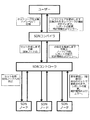
上記の導入で与えられたようなSDNの定義は、図1に示されるように(PCT / EP2014 / 055640参照図1、35ページ)、
以下の成分を含むシステムに本発明の発明者を導く。
1.上位レベルのネットワーク仕様でネットワークを定義するユーザー。
2.高水準ネットワーク仕様を、物理的および仮想的なネットワーキングおよびコンピューティングリソース用の一連の命令に変換するSDNコンパイラ。
3.この一連の命令を物理的および仮想的なネットワーキングおよびコンピューティングリソースに配布するSDNコントローラ。
4.物理的および仮想的なネットワーキングおよびコンピューティングリソースは、受信したセットの命令に従って着信パケットに対してアクションを実行する。 図1では、それらは「SDNノード」という用語で示されている。
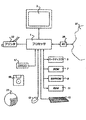
上記のポイント1で言及されたユーザは、人、ネットワーク管理システム、クラウド管理システム、アプリケーション、別のSDNコンパイラであってもよいが、これに限定されない。したがって、ユーザは、「ユーザ機器」、すなわちスタンドアロンまたはより大きなネットワークの一部であり得るコンピュータワークステーションのような任意の適切なコンピュータ機器を指すことができる。このようなコンピュータ機器の一例が図10に示されており、後で説明する。
PCT / EP2014 / 055640, a prior art that has not been published in advance,
A compiler and method for Software Defined Networking (SDN) is described. The following summarizes the main elements of the method. However, it should be noted that all features already described in PCT / EP2014 / 0055640 are also applicable to the present invention. Also, combinations with features / examples as described in PCT / EP2014 / 0055640 not explicitly described herein are also possible embodiments within the context of the present invention. Accordingly, all text of PCT / EP2014 / 0055640 referenced below is incorporated herein by reference.
The definition of SDN as given in the introduction above, as shown in Figure 1 (see PCT / EP2014 / 0555640 Figure 1, page 35),
The inventor of the present invention is led to a system including the following components.
1. A user who defines a network with a high-level network specification.
2. An SDN compiler that translates high-level network specifications into a set of instructions for physical and virtual networking and computing resources.
3. An SDN controller that distributes this set of instructions to physical and virtual networking and computing resources.
4. Physical and virtual networking and computing resources perform actions on incoming packets according to the received set of instructions. In FIG. 1, they are indicated by the term “SDN node”.
The user mentioned in the
図1において、下から上への方向で、様々な構成要素が、特定のタスクが実行されたことを彼らのノースバウンドインターフェースに報告し、変化、統計およびエラーを報告する。
ポイント4で言及されたリソースは、限定されないが、
・ 物理的なパケット転送デバイス(レイヤ2スイッチ、レイヤ3ルータ、ファイアウォール、ディープパケット検査デバイス、キャッシングノード、またはその他のタイプのミドルボックスなど)
・ 物理サーバ、パーソナルコンピュータ、ラップトップ、タブレット、携帯電話などのネットワークホストとして動作する物理的デバイスは、
・ 物理ネットワークインターフェイスカード(NIC)、
・ 仮想化された物理サーバの仮想スイッチ、
・ 仮想化された物理サーバ内の仮想マシン、
・ 仮想NIC、
・ IPv4対応ルーター、IPv6対応ルーター、MPLSスイッチ[MPLS = Multi Protocol Label Switching]、パケット交換を提供するアプリケーションプロセス、
・ 一例としての回路交換ノードは、これに限定されるものではないが、ファイバクロスコネクトクロスコネクト光ファイバ、リモート光アド/ドロップマルチプレクサ (Remote-Optical Add/Drop Multiplexers : ROADMs) または光クロスコネクトが光波長をクロスコネクトする場合、同期デジタル階層 (Synchronous Digital Hierarchy : SDH) マルチプレクサまたは同期光ネットワーク (Synchronous Optical NETwork : SONET) タイムスロットをクロスコネクトするマルチプレクサ、
・ OS(オペレーティングシステム)カーネル、
・ アプリケーションプロセス、
・ 物理ノードまたは仮想ノードの入力バッファおよび出力バッファ、
・ ファイバチャネルオーバーイーサネット(FCoE)をサポートするストレージ装置またはファイバチャネルオーバーIP(FCIP)をサポートするストレージ装置、
・ 波長分割多重(Wavelength Division Multiplexing : WDM)マルチプレクサ、
上述した各層の物理ノードおよび/または仮想ノードは、パケット交換ノードまたは回線交換ノードのいずれかである。 パケット交換ノードと回線交換ノードの両方に対して、一連の命令がSDNコンパイラによって作成される。 パケット交換ノードの場合、
これらの命令は転送テーブルエントリを含む。 回線交換ノードの場合、これらの命令は相互接続設定を構成します。
In FIG. 1, from bottom to top, various components report to their northbound interface that a particular task has been performed, and report changes, statistics, and errors.
The resources mentioned in point 4 are not limited,
• Physical packet forwarding devices (such as
-Physical devices that act as network hosts, such as physical servers, personal computers, laptops, tablets, mobile phones,
Physical network interface card (NIC),
-Virtual switch of virtualized physical server,
A virtual machine in a virtualized physical server,
・ Virtual NIC,
・ IPv4-compatible router, IPv6-compatible router, MPLS switch [MPLS = Multi Protocol Label Switching], application process that provides packet switching,
-Circuit switching nodes as an example include, but are not limited to, fiber cross-connect cross-connect optical fibers, remote optical add / drop multiplexers (ROADMs) or optical cross-connects When cross-connecting wavelengths, a Synchronous Digital Hierarchy (SDH) multiplexer or a Synchronous Optical NETwork (SONET) multiplexer that cross-connects time slots,
OS (Operating System) kernel,
Application processes,
-Physical and virtual node input and output buffers,
-Storage devices that support Fiber Channel over Ethernet (FCoE) or storage devices that support Fiber Channel over IP (FCIP)
・ Wavelength Division Multiplexing (WDM) multiplexer,
The physical nodes and / or virtual nodes in each layer described above are either packet switching nodes or circuit switching nodes. A series of instructions are created by the SDN compiler for both packet-switched and circuit-switched nodes. For packet switching nodes:
These instructions include forwarding table entries. For circuit-switched nodes, these instructions configure the interconnect settings.
上述のリソースは、限定はしないが例えば物理的NIC及び物理的パケット転送装置のような物理的装置のような物理的装置の両方の構成要素を含むことに留意されたい。 したがって、ポイント4で参照される一連の命令は、
物理デバイスのコンポーネントまたは物理デバイス全体に対して作成できます。
仮想マシンなどの仮想リソースを表す仮想ノードは、この方法において物理ノードとして表されることに留意されたい
(PCT / EP2014 / 055640ページ186参照)。
論理ネットワーク抽象化の仕様は、ユーザによって入力され、上記のポイント1で言及された「高レベルネットワーク仕様」である。理想的には、この仕様は、任意のトポロジ内の任意の数の論理ノードで構成された任意の論理ネットワークを指定します。論理ノードは、任意の物理および仮想ネットワークとコンピューティングリソースにマッピングされます。複数の論理ネットワークは、同じ物理的および仮想的なネットワーキングおよびコンピューティングリソース上で同時に定義および作成できます。
It should be noted that the resources described above include components of both physical devices such as, but not limited to, physical devices such as physical NICs and physical packet forwarding devices. Therefore, the sequence of instructions referenced at point 4 is
Can be created for a physical device component or an entire physical device.
Note that virtual nodes representing virtual resources such as virtual machines are represented as physical nodes in this way (see PCT / EP2014 / 0555640 page 186).
The specification of the logical network abstraction is the “high-level network specification” input by the user and mentioned in
上記のポイント2は、「ネットワークとコンピューティングリソースのための高水準ネットワーク仕様の一連の命令への変換」を指しています。パケット転送スイッチの場合、これらの命令は、どのパケットを転送すべきかに応じて、そのスイッチの転送テーブルエントリである。ホストの場合、これらの命令は、どのパケットを受け入れるか、またはドロップするか、出力ポートがそのホストノードから特定の宛先ノードに発信するパケットを送信するための指示に従って、フィルタテーブルエントリである。
NICの場合、これらの命令は、パケットを転送または廃棄すべきフィルタテーブルエントリである。上で言及したポイント2は、高レベルのネットワーク仕様から、適切な物理的および仮想的なネットワークおよびコンピューティング資源のための命令セットへの変換またはコンパイルを提供する。我々は、このプロセスをコンピューティングで使用されるコンパイラに類似した「SDNコンパイラ」プロセスと呼んでおり、高水準言語を低レベル命令に翻訳しています。
In the case of a NIC, these instructions are filter table entries that should forward or drop the packet.
上記のプロセスは、いわゆる「オーバーレイ」仮想ネットワーク(Nicira / VMWareなどの提案されたものなど)とは対照的に、物理的および仮想的なネットワーキングおよびコンピューティングリソースへの指示を提供しなければならないことに注意してください。 トンネルの入出力スイッチを除いて、物理スイッチを構成することなく、物理ネットワークに接続できます。
望ましいSDNコンパイラメソッドは、物理ネットワーク全体を含む仮想リソースと物理リソースの両方を含む包括的なアプローチを提供する必要があります。さらに、所望のSDNコンパイラ方法は、上述の非スイッチングネットワーク装置に必要な命令を指示する必要がある。さらに、現在のOpenFlow実装がソフトウェア(例えばOpen vSwitchは、
仮想化された物理サーバーで実行中の仮想スイッチを提供します)ならびにハードウェア(例えばNEC ProgrammableFlow PF5240スイッチ)で利用可能であるため、仮想および物理ネットワーキングおよびコンピューティングリソース全体にわたって前述の命令を決定する必要がある。実装では、「SDNコンパイラ」の機能、またはその一部、および「SDNコントローラ」の機能、またはその少なくとも一部を1つのシステムに結合することができます。
次に、機能表現を使用してSDNコンパイラが適切な命令を作成するための物理リソースと仮想リソースについて説明します。
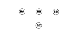
図2A、図2B、図2Cおよび図2D(PCT / EP2014 / 055640図2A、2B、2F、2Gページ37を参照)は、物理ネットワークの構成要素を示す。例示的な物理ノードは図2Aに示され、論理ネットワークが作成される物理リソースと見なされる。そのため、物理ノードの名前(図2AのBA〜BD)は物理リソースを識別するためにのみ使用され、転送の決定には使用されません。図2Bに示すように、我々は、物理的なネットワークの集合(図2Bの
BAAで識別される)を物理的ノードの集合として定義する。 物理ノードは、物理リンク(実線で示す)によって相互接続されています。
物理リンクが双方向である場合、物理リンクは、各方向の1つの隣接関係である一対の物理ノード間に隣接関係のペアを作成します。 物理リンクが単方向である場合、物理リンクは一対の物理ノード間に単一の隣接関係を作成する。物理的リンクは、光ファイバケーブル、銅ケーブル、空気を含むが、これに限定されない任意の物理的媒体とすることができる。 物理的リンクは、光波長、時分割多重(TDM)回路、マルチプロトコルラベルスイッチング(MPLS)パスなどの他のネットワーキング技術によって提供される経路であってもよい。物理リンクのセットと組み合わされた物理ノードのセットは、ネットワークの物理トポロジーを決定します。 物理ネットワークは任意の数のノードと任意のリンクで構成することができ、その結果、任意のトポロジが得られます。
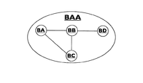
物理ネットワークの典型的な表現が、物理ネットワークBAAおよび物理ノードBA〜BDを示す図2Cに示されている。図2Cに示すように、物理ノードと物理リンクとの間のインタフェースは、物理的な「アタッチメントポイント」(Point-of-Attachment)(PoA)と呼ばれ、p101からp108で示される。
The above process must provide instructions to physical and virtual networking and computing resources as opposed to so-called “overlay” virtual networks (such as those proposed by Nicira / VMWare etc.) Please be careful. You can connect to a physical network without configuring a physical switch, except for tunnel input / output switches.
A desirable SDN compiler method should provide a comprehensive approach that includes both virtual and physical resources, including the entire physical network. Furthermore, the desired SDN compiler method needs to indicate the necessary instructions to the non-switching network device described above. In addition, the current OpenFlow implementation is software (eg Open vSwitch,
Provides virtual switches running on virtualized physical servers) and hardware (eg NEC ProgrammableFlow PF5240 switches), so determine the above instructions across virtual and physical networking and computing resources There is a need. Implementations can combine "SDN Compiler" functionality, or part of it, and "SDN Controller" functionality, or at least part of it, into a single system.
The following describes physical and virtual resources that allow the SDN compiler to create appropriate instructions using functional representation.
2A, 2B, 2C and 2D (see PCT / EP2014 / 0555640 FIGS. 2A, 2B, 2F, 2G page 37) show the components of the physical network. An exemplary physical node is shown in FIG. 2A and is considered a physical resource on which a logical network is created. Therefore, the name of the physical node (BA to BD in Figure 2A) is only used to identify the physical resource, not the transfer decision. As shown in Figure 2B, we have a set of physical networks (Figure 2B
Defined as a set of physical nodes. Physical nodes are interconnected by physical links (shown as solid lines).
If the physical link is bidirectional, the physical link creates an adjacency pair between a pair of physical nodes that are one adjacency in each direction. If the physical link is unidirectional, the physical link creates a single adjacency between a pair of physical nodes. The physical link can be any physical medium including but not limited to fiber optic cable, copper cable, air. The physical link may be a path provided by other networking technologies such as optical wavelengths, time division multiplexing (TDM) circuits, multi-protocol label switching (MPLS) paths. A set of physical nodes combined with a set of physical links determines the physical topology of the network. A physical network can consist of any number of nodes and any link, resulting in any topology.
A typical representation of a physical network is shown in FIG. 2C showing physical network BAA and physical nodes BA-BD. As shown in FIG. 2C, the interface between the physical node and the physical link is called a physical “attachment point” (PoA) and is indicated by p101 to p108.
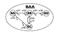
現在配備されているネットワークにおける物理PoA識別子の典型的な例は、イーサネット(登録商標)媒体アクセス制御(MAC)アドレスであるが、本発明はこれに限定されない。 PoA識別子は、SDNコンパイラの制御下にあるネットワークの集合内で一意でなければならない。PoAは、パケットまたは信号がノードによって受信されたときのノードの「入力ポート」と、ノードからパケットまたは信号が送信されたときのノードの「出力ポート」の両方を識別する。図2Cに示すように、各物理リンクは、1つまたは複数のコストタイプと、各方向の各コストタイプに関連付けられたコスト値を有する。物理ネットワークで使用される典型的なコストタイプはリンクの遅延であり、コスト値は典型的にはミリ秒で表されるが、前記リンクの特性を表す任意のタイプのコストを使用することができる。
各双方向物理リンクには2つのコスト値があり、各方向に1つずつあります。 各単方向物理リンクには、各コストタイプごとに1つのコスト値があります。特定の方向の物理リンクのコスト値は、パケットがその特定の方向に由来する物理ノードに最も近いものとして示される。たとえば、BAからBBへのリンクのコスト値は1です。BBからBAへのリンクのコスト値は3です。物理リンクは、一対の物理ノード間の隣接関係を表すが、物理パスとは、ユニキャストネットワーキングの場合、物理ソースノードから物理デスティネーションノードにパケットまたは信号が続く物理ルートを示す。
マルチキャストまたはブロードキャストネットワークの場合、単一の物理ソースノードと複数の物理的な宛先ノードとの間に物理的なパス関係があります。次に、物理ノードは、深さマッピングを介して複数の論理ノードにマッピングされ、結果としてマルチキャストされ、物理パスは、各方向に複数のコストタイプを有することができ、一般に、その特定のコストタイプのコスト値の合計 それが構成する物理リンクの特定の方向。物理パスは、パケットが送信元ノードから宛先ノードへと通過する一連の物理PoAである。「パス」の別の用語は「フロー」である。 OpenFlow仕様は用語「フロー」を使用する。
ネットワークを有向グラフとしても表現します。 前記有向グラフは重み付けされてもよい。ネットワークBAAの有向グラフは図2Dに示されており、頂点(ノード)BAからBDと、頂点の対を接続する有向枝とを示している。図2Dでは、「エッジ」は、矢印の方向がデータのフローの方向を示す別の頂点と1つの頂点を結ぶ矢印で示されている。有向グラフとして表される場合、2つの頂点間の双方向物理リンクは2つのエッジによって表される。各エッジは隣接に対応します。
PCT / EP2014 / 055640(39頁、41頁、42頁)は、これらの用語の一般的な使用に従って、物理スイッチノード、物理ホストノード、物理NIC、仮想スイッチノードおよび仮想ホストノードの特性を記述している。限定ではないが、ホストノードは、コンピューティング機器または記憶装置である(例えば、PCT / EP2014 / 055640の155および204頁参照)。
これまで、物理的および仮想的なネットワーキングおよびコンピューティングリソースの機能モデルを提供してきました。ここで、本発明を説明するために、高水準仕様で定義することができ、物理および仮想リソースから独立した論理ネットワークを考える。
論理ネットワークは、以下を指定することによって定義されます:
1. 論理ネットワークの名前
2. 論理ネットワークが構成されている論理ノードの名前
3. 論理ノード間の隣接関係
4. 論理ネットワークの1つ以上のコストタイプ
5. 各コストタイプの論理ノード間の論理的隣接関係のコスト
6. 論理ネットワークのフォワーディングポリシー
7. 物理ノードおよび/または仮想ノードから論理ノードへのマッピング
コストタイプと値はリンクのプロパティを表し、転送ポリシーを決定するために使用できます。
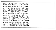
上記で説明した物理ノードおよび/または仮想ノードは、以下のように1:1,1:nまたはn:1マッピングを使用して論理ノードにマッピングされる:
- 物理マッピングから論理マッピングへの1:1
- 1:n物理マッピングから論理マッピング
- n:1物理から論理へのマッピング
- 仮想マッピングから論理マッピングへの1:1
- 1:n仮想から論理へのマッピング
- n:1仮想から論理へのマッピング
- n:1物理および仮想から論理へのマッピング
上述のように、仮想ノードは、上記のマッピングを減らす方法(PCT / EP2014 / 055640、186頁参照)において、物理ノードとして表される:
- 物理マッピングから論理マッピングへの1:1
- 1:n物理マッピングから論理マッピング
- n:1物理から論理へのマッピング
図3Cに示すように、論理ノードの機能表現は破線の円である。物理/仮想から論理へのマッピングは、マッピングの各方向について任意のコスト値を有することができる。
SDNコンパイラのユーザは、論理ネットワークを定義します。ユーザは、人、ネットワーク管理システム、クラウド管理システム、アプリケーション、別のSDNコンパイラであってもよいが、これに限定されない。論理ネットワークは、任意の論理的な隣接関係を持つ任意の数の論理ノードで構成することができ、結果として任意の論理トポロジーが得られます。一例として、論理ネットワークは、論理ノードがマッピングされた物理および/または仮想ノードが各論理ノードの属性である高レベルプログラミング言語のグラフとして指定することができる。
論理ノードでは、物理リソースと仮想リソースの名前空間から独立した論理名空間を使用します。論理ネットワークは、任意の適切な数の一意の文字で任意の適切な形式で表現され、必要に応じて適切な仮想および物理リソースにマッピングされる論理ノード名に関して定義することができる。このマッピングを変更することにより、論理ネットワークを他の仮想および物理リソースに再マップすることができます。
A typical example of a physical PoA identifier in a currently deployed network is an Ethernet medium access control (MAC) address, but the invention is not so limited. The PoA identifier must be unique within the set of networks under the control of the SDN compiler. PoA identifies both the “input port” of a node when a packet or signal is received by the node and the “output port” of the node when a packet or signal is transmitted from the node. As shown in FIG. 2C, each physical link has one or more cost types and a cost value associated with each cost type in each direction. A typical cost type used in physical networks is link latency, and cost values are typically expressed in milliseconds, but any type of cost that represents the characteristics of the link can be used. .
Each bidirectional physical link has two cost values, one in each direction. Each unidirectional physical link has one cost value for each cost type. The cost value of a physical link in a particular direction is shown as being closest to the physical node from which the packet originates in that particular direction. For example, the cost value for a link from BA to BB is 1. The cost value of the link from BB to BA is 3. A physical link represents an adjacency relationship between a pair of physical nodes. In the case of unicast networking, a physical path indicates a physical route in which a packet or signal continues from a physical source node to a physical destination node.
For multicast or broadcast networks, there is a physical path relationship between a single physical source node and multiple physical destination nodes. Next, a physical node is mapped to multiple logical nodes via depth mapping, resulting in multicast, and a physical path can have multiple cost types in each direction, generally its specific cost type The total cost value of the specific direction of the physical link that it comprises. A physical path is a series of physical PoAs through which a packet passes from a source node to a destination node. Another term for “pass” is “flow”. The OpenFlow specification uses the term “flow”.
The network is also expressed as a directed graph. The directed graph may be weighted. The directed graph of the network BAA is shown in FIG. 2D and shows the vertices (nodes) BA to BD and the directional branch connecting the vertex pairs. In FIG. 2D, an “edge” is indicated by an arrow connecting one vertex with another vertex in which the direction of the arrow indicates the direction of data flow. When represented as a directed graph, a bidirectional physical link between two vertices is represented by two edges. Each edge corresponds to an adjacency.
PCT / EP2014 / 055640 (page 39, page 41, page 42) describes the characteristics of physical switch nodes, physical host nodes, physical NICs, virtual switch nodes and virtual host nodes according to the general use of these terms ing. Without limitation, the host node is a computing device or storage device (see, eg, PCT / EP2014 / 0555640, pages 155 and 204).
So far, we have provided a functional model of physical and virtual networking and computing resources. To illustrate the present invention, consider a logical network that can be defined with high-level specifications and is independent of physical and virtual resources.
A logical network is defined by specifying:
1. Name of the logical network
2. Name of the logical node in which the logical network is configured
3. Adjacency between logical nodes
4. One or more cost types for the logical network
5. Cost of logical adjacency between logical nodes of each cost type
6. Logical network forwarding policy
7. Physical node and / or virtual node to logical node mapping
Cost types and values represent link properties and can be used to determine forwarding policies.
The physical nodes and / or virtual nodes described above are mapped to logical nodes using 1: 1, 1: n or n: 1 mapping as follows:
-1: 1 from physical to logical mapping
-1: n physical mapping to logical mapping
-n: 1 physical to logical mapping
-1: 1 virtual mapping to logical mapping
-1: n Virtual to logical mapping
-n: 1 virtual to logical mapping
-n: 1 physical and virtual to logical mapping
As mentioned above, virtual nodes are represented as physical nodes in the method of reducing the above mapping (see PCT / EP2014 / 0555640, page 186):
-1: 1 from physical to logical mapping
-1: n physical mapping to logical mapping
-n: 1 physical to logical mapping
As shown in FIG. 3C, the functional representation of the logical node is a dashed circle. The physical / virtual to logical mapping can have an arbitrary cost value for each direction of the mapping.
SDN compiler users define logical networks. The user may be a person, a network management system, a cloud management system, an application, or another SDN compiler, but is not limited thereto. A logical network can consist of any number of logical nodes with any logical adjacency resulting in any logical topology. As an example, a logical network may be specified as a graph in a high level programming language in which physical and / or virtual nodes to which logical nodes are mapped are attributes of each logical node.
Logical nodes use a logical namespace that is independent of the physical and virtual resource namespaces. A logical network can be defined in terms of logical node names that are represented in any suitable form with any suitable number of unique characters and mapped to the appropriate virtual and physical resources as required. By changing this mapping, you can remap the logical network to other virtual and physical resources.
1:n物理マッピングから論理マッピングでは、複数の論理名を持つ単一の物理リソースに名前を付けることができます。1:n仮想から論理へのマッピングにより、複数の論理名を持つ単一の仮想リソースに名前を付けることができます。論理ネットワークは、物理ネットワークと仮想リソースから独立していることに注意してください。もちろん、物理リソースと仮想リソースの間にはパスが存在するため、物理ネットワークと仮想リソースの抽象化を提供します。
論理ノードの名前は、転送決定を行うために使用されます(PCT / EP2014 / 055640の47ページを参照)。論理ノード自体は、インタフェースではなく名前が付けられています。物理ネットワークに類似して、論理ネットワークを論理ノードの集合として定義する。論理ノードは論理リンク(実線で示す)によって相互接続される。論理リンクが双方向である場合、論理リンクは一対の論理ノード間に隣接関係のペアを作成する。論理リンクが単方向である場合、論理リンクは一対の物理ノード間に単一の隣接関係を作成する。論理リンクの組と組み合わされた論理ノードのセットは、ネットワークの論理トポロジを決定する。
論理リンクは、一対の論理ノード間の隣接関係を表すが、論理パスは、ユニキャストネットワーキングの場合に、パケットが論理ソースノードから論理宛先ノードに続く論理ルートを示す。マルチキャストまたはブロードキャストネットワーキングの場合、単一の論理ソースノードと複数の論理宛先ノードとの間に論理的経路関係が存在する。論理パスは、物理的PoAおよび/または仮想PoAのシーケンスであり、これを介して、パケットは、論理ソースノードから論理宛先ノードまで横断する。ここでは、重要な関係に到達しました。論理的な送信元ノードと論理的な宛先ノードの間の関係、および物理PoAと仮想PoAの観点から記述されたパスです。これにより、論理ノード名でネットワークを定義し、定義されたネットワークを、物理的および/または仮想的なネットワーキングおよび/またはコンピューティングリソースの物理PoAおよび/または仮想PoAの観点から命令に翻訳(コンパイル)することが可能になる。
論理ネットワークは、物理ネットワーク、仮想ネットワーク、または結合された物理/仮想ネットワークから作成することができる(PCT / EP2014 / 055640の93ページ参照)。また、別の論理ネットワークから論理ネットワークを作成することもできます。曖昧さを避けるために、以下では、深さ(d-1)
のネットワークから作成された深さdのネットワークを参照する。特定の深さを深度dと呼び、dは0(ゼロ)から始まる正の整数です。深さd = 0はこれまで参照された物理ネットワークまたは仮想ネットワークに等しい。奥行きd> = 1はこれまで参照されている論理ネットワークに等しい。
1: n physical mapping to logical mapping allows you to name a single physical resource with multiple logical names. 1: n Virtual to logical mapping allows you to name a single virtual resource with multiple logical names. Note that logical networks are independent of physical networks and virtual resources. Of course, there is a path between the physical resource and the virtual resource, so it provides an abstraction between the physical network and the virtual resource.
The name of the logical node is used to make the forwarding decision (see page 47 of PCT / EP2014 / 0555640). Logical nodes themselves are named, not interfaces. Similar to a physical network, a logical network is defined as a set of logical nodes. The logical nodes are interconnected by logical links (indicated by solid lines). When the logical link is bidirectional, the logical link creates an adjacency pair between a pair of logical nodes. If the logical link is unidirectional, the logical link creates a single adjacency between a pair of physical nodes. A set of logical nodes combined with a set of logical links determines the logical topology of the network.
A logical link represents an adjacency relationship between a pair of logical nodes, while a logical path indicates a logical route that a packet follows from a logical source node to a logical destination node in the case of unicast networking. In the case of multicast or broadcast networking, a logical path relationship exists between a single logical source node and multiple logical destination nodes. A logical path is a sequence of physical PoA and / or virtual PoA through which a packet traverses from a logical source node to a logical destination node. Here we have reached an important relationship. A path written from the perspective of a physical PoA and a virtual PoA, as well as the relationship between the logical source node and the logical destination node. This defines a network with logical node names and translates (compiles) the defined network into instructions from the physical and / or virtual PoA point of view of physical and / or virtual networking and / or computing resources It becomes possible to do.
Logical networks can be created from physical networks, virtual networks, or combined physical / virtual networks (see page 93 of PCT / EP2014 / 055640). You can also create a logical network from another logical network. To avoid ambiguity, the depth (d-1)
Refers to a network of depth d created from the network. The specific depth is called depth d, where d is a positive integer starting from 0 (zero). The depth d = 0 is equal to the physical network or virtual network referenced so far. Depth d> = 1 is equal to the logical network referenced so far.
結合された物理および仮想ネットワークは、1つまたは複数の層からなる(PCT / EP2014 / 055640の91頁参照)。
各層において、ノードは、物理リンクおよび/または仮想リンクによって相互接続することができる。 物理的リンクは、光ファイバケーブル、銅ケーブル、空気を含むが、これに限定されない任意の物理的媒体とすることができる。物理的リンクは、光波長、時分割多重(Time Division Multiplexing)(TDM)回路、
マルチプロトコルラベルスイッチング (Multi Protocol Label Switching)(MPLS)経路などの他のネットワーキング技術によって提供される経路であってもよい。物理リンクは、GREトンネル[GRE =汎用ルーティングカプセル化 (Generic Routing Encapsulation)]、NVGREトンネル[NVGRE =汎用ルーティングカプセル化を使用したネットワーク仮想化 (Network Virtualization using Generic Routing Encapsulation)]、VXLANトンネル[VXLAN = 仮想拡張可能ローカルエリアネットワーク (Virtual Extensible Local Area Network)]。仮想リンクは、仮想スイッチと仮想マシン間の仮想リンク、仮想マシン間の仮想リンク、ネットワークソケットなどの仮想接続とすることができます。レイヤーは上位レイヤーにサービスを提供し、下位レイヤーからサービスを消費する可能性があります。最も低いパケット交換層は、媒体アクセス制御(MAC)を提供する。論理ネットワークは、1つ以上の層で構成されています。
特定のレイヤーをレイヤーnと呼びます。nは、n_minから始まる正の整数で、0(ゼロ)の値を持つことがあります。深さdにおいて、層n = n_min(d)を「最下層」と呼ぶ。 (PCT / EP2014 / 055640,93,141頁参照)。現在のネットワークにおける層の例は、物理媒体層、周波数または波長分割多重化層、時分割多重化層、データリンク層、ネットワーク層、トランスポート層、アプリケーション層であるが、これらに限定されない。全体的なネットワーク内で、レイヤnはサービスをレイヤ
(n + 1)に提供し、レイヤ(n + 1)はレイヤnによって提供されるサービス
を消費する。
各層は、任意の数の階層レベルを有するサブネットワークの階層内の任意の数のサブネットワークからなる。ネットワークはノードに抽象化することができ、別のネットワーク内のノードになることができます。一例として、図2Cに示されるネットワークBAAは、ネットワークネットワーク内のノードに抽象化することができるが、これに限定されない。以下では、あいまいさを避けるために、レベル(h-1)のネットワークからなるレベルhのネットワークを参照し、
最下位階層レベルを深さdおよびレイヤnのh_min(d、n)とみなす(PCT / EP2014 / 055640,93および146頁参照)。レベルh_min(d、n)のネットワークはノードです。これは、物理ネットワークと論理ネットワークに適用されます。この用語を使用して、図2Dに示すレベルhの物理ネットワークBAAは、レベル(h-1)における物理ネットワークBA、BB、BC、BDからなる。
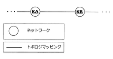
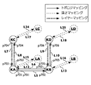
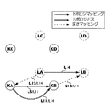
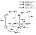
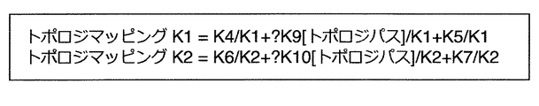
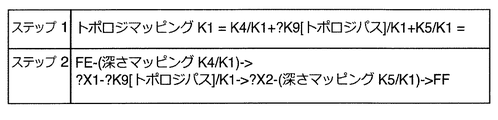
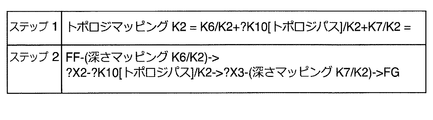
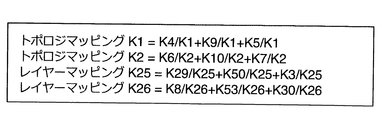
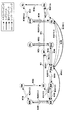
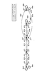
上記は、図3A~3Dに示されている(PCT / EP2014 / 055640図33A、33B、33C、34A、94頁参照)。図3Aは、同じレベルhにあり、リンクによって相互接続されているネットワークKAおよびKBを示す。図3Aに示すように、ネットワークKAおよびネットワークKBは、他のネットワークにも相互接続することができる。ネットワーク間の関係は、マッピングと呼ばれます。以下で紹介する様々なマッピングのための一貫した命名を得るために、以下の本文のリンクのモデリングにおける隣接関係ではなく、トポロジマッピングを参照します。リンクが双方向である場合、リンクは一対のネットワーク間に一対のトポロジマッピングを作成する。リンクが単方向である場合、リンクは一対のネットワーク間で単一のトポロジマッピングを作成します。トポロジマッピングは、第1のネットワークから第2のネットワークへのマッピングであり、第1および第2のネットワークは同じ深さd、同じレイヤnおよび同じレベルhにある(PCT / EP2014 / 055640図49、ページ179参照)
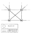
図3Bは、同じレベルhにあるネットワークKA、KB、KC、KDを示す。 ネットワークKAおよびKBは、トポロジマッピングとして表されるリンクによって相互接続されている。ネットワークKAとKCは、リンクによって相互接続され、レイヤーマッピングとして表されます。ネットワークKBとKCは、レイヤーマッピングとして表されるリンクによって相互接続されています。レイヤマッピングは、第1のネットワークから第2のネットワークへのマッピングであり、第1および第2のネットワークは異なるレイヤnにある。
図3Cのネットワークでは、KA、KB、KC、KD、LA、LB、LC、LDが示されている。この図では、各ネットワークは同じレベルhを有する。
階層レベルがh = 0で始まる場合、
図3Cのh = 0のネットワークはこれまで参照された「ノード」に等しい。
h = 1の場合、図3Cのネットワークは、
以下で参照される「ノードのネットワーク」に等しい。
h = 2の場合、図3のネットワークは、
以下で参照される「ノードのネットワークネットワーク」などに等しい。各ネットワークは、特定の深さdおよび層nに位置する。ネットワークKAおよびKBが深さd、層n、ネットワークKCおよびKDは深度dにあり、層(n + 1)、
ネットワークLAおよびLBは、深さ(d + 1)、層n、ネットワークLCおよび
LDは深さ(d + 1)、層(n + 1)にある。
特定のレベルhでネットワーク間の3種類のマッピングを区別する(PCT / EP2014 / 055640の94,128および129頁参照):
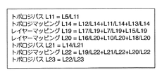
- トポロジマッピングは、同じ深度dとレイヤnを持つネットワーク間の隣接関係です。隣接関係はマッピングであることに注意してください。トポロジマッピングは、ネットワーク(d, n, h)からネットワーク(d, n, h)へのマッピングとして定義されます。図3Aは、図が3次元に限定されるので、2つのネットワーク(KAとKB、KCとKD、LAとLB、LCとLD)間のトポロジマッピングのみを示す。一般に、トポロジマッピングは任意の数のネットワーク間に存在し、通常は2次元レイアウトとして提示され、ここに提示されたSDNコンパイラ方法によってサポートされる。トポロジマッピングは実線で示されています。物理から仮想へのマッピングは、物理ノードと仮想ノード間の特別なタイプのトポロジマッピングです。
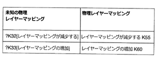
- レイヤマッピングは、異なるレイヤnおよび同じ深さdのネットワーク間の関係です。レイヤマッピングは、(d, n, h)のネットワークからd, n-y, h)のネットワークへのマッピングまたはd, n-y, h)のネットワークからd, n, h)のネットワークへのマッピングとして定義されます、yが0より大きくかつn-n_min(d)以下である場合、n_min(d)は深度dで最下位層である。レイヤーマッピングはストライプとして表示されます。
- 深度マッピングは、異なる深さのネットワーク間の関係であるd。深さマッピングは、(d, n1, h)のネットワークから(d-x, n2, h)のネットワークへのマッピングまたは(d-x, n1, h)のネットワークから(d, n2, h)のネットワークへのマッピングとして定義され、xはゼロより大きく、 またはdに等しく、n1はn2に等しくてもよい。深度マッピングは破線で示されている。
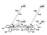
物理ノードの機能表現は、図3Aに示すように、黒丸の円である。図3Aに示すように、論理ノードの機能的表現は破線の円である。図3Aにおいて、ネットワークKAとネットワークLDとの間、ネットワークKBとネットワークLCとの間、ネットワークKCとネットワークLBとの間、ネットワークKDとネットワークLAとの間の深さマッピングは、図を比較的単純に保つために示されていない。図3Aのトポロジマッピングでは、単一のネットワークKA、KB、KC、KD、LA、LB、LC、またはLDにのみ接続され、 'で終端されたレイヤマッピングおよび深さマッピングが示されている。 。 。 '反対側に。任意の数のレイヤに拡張できることを示しています。単一のネットワークにのみ接続された深度マッピングは、深度マッピングを任意の深さの数に拡張できることを示している。レベルhの単一のネットワークにのみ接続されたトポロジマッピングは、以下に説明するように、レベル(h + 1)でのトポロジマッピングを示す。
異なるレベルのネットワーク間では、レベルマッピングを考慮します:
- レベルマッピングは、異なるレベル、
同じ深さd、同じレイヤnのネットワーク間の関係です。
レベルマッピングは、(d, n, h)から(d, n, h-z)
のネットワークへのマッピングまたは(d, n, h-z)のネットワークから(d, n, h)のネットワークへのマッピングとして定義されます.zはゼロより大きく、 h-h_min(d、n)に等しく、
h_min(d、n)は深さdおよびレイヤnにおける最低レベルである。
物理ノードではなく、深さd = 0、レイヤn、レベルh = h_min(d、n)のネットワークを参照します。
我々は、論理ノードではなく、深さd> = 1、レイヤn、レベルh = h_min(d、n)のネットワークを参照する。
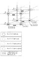
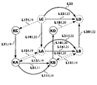
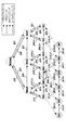
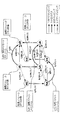
レベルマッピングが図3Dに示されている。図3Dは、レベルhのネットワーク
KA、KB、KC、KD、LA、LB、LC、LDおよびそれらのトポロジマッピング、レイヤマッピングおよび深度マッピング関係を示す。図3Cに示されたノード
KAとKD、KBとKC、LAとLD、LBとLCとの間の対角レイヤーマッピングは、図を簡略化するためにこの図では省略されている。図3Cに示されたノードKAとLA、KBとLA、KCとLD、KDとLC、KAとLC、KCとLA、KBとLD、KDとLBとの対角線の深さマッピングは、 図を単純化する。図3Dはまた、
レベル(h + 1)におけるネットワークKAA、KCC、LAA、LCCを示す。
ネットワークKAA(d,n,h+1)は、(d,n,h)にあるネットワークKAおよびKBを含み、言い換えると、ネットワークKAAは、レベルマッピングを介してネットワークKAおよびKBにマッピングされる。
ネットワークKCC(d,n+1,h+1)は、(d,n+1,h)にあるネットワークKCおよびKDを含み、言い換えると、ネットワークKCCは、レベルマッピングを介してネットワークKCおよびKDにマッピングされる。
ネットワークLAA(d+1,n,h+1)にはネットワークLAとLBの両方が(d+1,n,h)にあります。言い換えれば、ネットワークLAAはネットワークLAとLBにレベルマッピングされています。
ネットワークLCC(d+1,n+1,h+1)にはネットワークLCとLDの両方が
(d+1,n+1,h)にあります。言い換えれば、ネットワークLCCはネットワークLCとLDにレベルマッピングされています。
レベルマッピングが図4Aに示されている(PCT / EP2014 / 055640図42Aおよび42、146頁参照)。
The combined physical and virtual network consists of one or more layers (see page 91 of PCT / EP2014 / 055640).
At each layer, the nodes can be interconnected by physical links and / or virtual links. The physical link can be any physical medium including but not limited to fiber optic cable, copper cable, air. The physical link consists of optical wavelengths, time division multiplexing (TDM) circuits,
It may be a path provided by other networking technologies such as a Multi Protocol Label Switching (MPLS) path. The physical links are GRE tunnel [GRE = Generic Routing Encapsulation], NVGRE tunnel [NVGRE = Network Virtualization using Generic Routing Encapsulation], VXLAN tunnel [VXLAN = Virtual Extensible Local Area Network. Virtual links can be virtual links such as virtual links between virtual switches and virtual machines, virtual links between virtual machines, and network sockets. Layers provide services to higher layers and can consume services from lower layers. The lowest packet switching layer provides medium access control (MAC). A logical network consists of one or more layers.
A specific layer is called layer n. n is a positive integer starting with n_min and may have a value of 0 (zero). At depth d, layer n = n_min (d) is referred to as the “bottom layer”. (See PCT / EP2014 / 055640, 93, 141). Examples of layers in current networks are, but are not limited to, physical media layer, frequency or wavelength division multiplexing layer, time division multiplexing layer, data link layer, network layer, transport layer, application layer. Within the overall network, layer n provides services to layer (n + 1), and layer (n + 1) consumes the services provided by layer n.
Each layer consists of any number of sub-networks within a hierarchy of sub-networks having any number of hierarchical levels. A network can be abstracted into nodes and can be a node in another network. As an example, the network BAA shown in FIG. 2C can be abstracted to nodes in the network, but is not limited thereto. In the following, to avoid ambiguity, we will refer to a level h network consisting of level (h-1) networks,
The lowest hierarchical level is regarded as h_min (d, n) of depth d and layer n (see PCT / EP2014 / 0555640, 93 and 146). A network with level h_min (d, n) is a node. This applies to physical and logical networks. Using this terminology, the level h physical network BAA shown in FIG. 2D consists of physical networks BA, BB, BC, and BD at level (h−1).
The above is shown in FIGS. 3A-3D (see FIG. 33A, 33B, 33C, 34A, page 94, PCT / EP2014 / 0555640). FIG. 3A shows networks KA and KB at the same level h and interconnected by links. As shown in FIG. 3A, network KA and network KB can also be interconnected to other networks. The relationship between networks is called mapping. To obtain consistent naming for the various mappings introduced below, refer to topology mappings, not adjacencies in link modeling in the text below. If the link is bidirectional, the link creates a pair of topology mappings between the pair of networks. If the link is unidirectional, the link creates a single topology mapping between a pair of networks. Topology mapping is the mapping from the first network to the second network, where the first and second networks are at the same depth d, the same layer n and the same level h (PCT / EP2014 / 055640 Figure 49, (See page 179)
FIG. 3B shows networks KA, KB, KC, KD at the same level h. Networks KA and KB are interconnected by links represented as topology mapping. Networks KA and KC are interconnected by links and are represented as layer mappings. Networks KB and KC are interconnected by links represented as layer mappings. The layer mapping is a mapping from the first network to the second network, and the first and second networks are in different layers n.
In the network of FIG. 3C, KA, KB, KC, KD, LA, LB, LC, and LD are shown. In this figure, each network has the same level h.
If the hierarchy level starts with h = 0,
The network with h = 0 in FIG. 3C is equivalent to the “node” referred to so far.
For h = 1, the network in Figure 3C is
Equivalent to “Network of Nodes” referenced below.
For h = 2, the network in Figure 3 is
Equivalent to “node network network” and the like referred to below. Each network is located at a specific depth d and layer n. Networks KA and KB are at depth d, layer n, networks KC and KD are at depth d, layer (n + 1),
Networks LA and LB are depth (d + 1), layer n, network LC and
LD is in depth (d + 1), layer (n + 1).
Distinguish three types of mapping between networks at a specific level h (see PCT / EP2014 / 0555640
-Topology mapping is the adjacency between networks with the same depth d and layer n. Note that the adjacency is a mapping. Topology mapping is defined as a mapping from network (d, n, h) to network (d, n, h). FIG. 3A shows only the topology mapping between the two networks (KA and KB, KC and KD, LA and LB, LC and LD) because the figure is limited to three dimensions. In general, topology mapping exists between any number of networks, usually presented as a two-dimensional layout, and supported by the SDN compiler method presented here. Topology mapping is shown as a solid line. Physical to virtual mapping is a special type of topology mapping between physical and virtual nodes.
-Layer mapping is the relationship between networks of different layer n and same depth d. Layer mapping is defined as mapping from (d, n, h) network to d, ny, h) network or from d, ny, h) network to d, n, h) network , Y is greater than 0 and less than or equal to n-n_min (d), n_min (d) is the lowest layer at depth d. Layer mappings are displayed as stripes.
-Depth mapping is a relationship between networks of different depths. Depth mapping is from (d, n1, h) to (dx, n2, h) or from (dx, n1, h) to (d, n2, h) X may be greater than zero or equal to d and n1 may be equal to n2. Depth mapping is shown with dashed lines.
The functional representation of the physical node is a black circle as shown in FIG. 3A. As shown in FIG. 3A, the functional representation of a logical node is a dashed circle. In FIG. 3A, the depth mapping between network KA and network LD, between network KB and network LC, between network KC and network LB, and between network KD and network LA is relatively simple. Not shown to keep on. The topology mapping of FIG. 3A shows a layer mapping and depth mapping connected only to a single network KA, KB, KC, KD, LA, LB, LC, or LD and terminated with a '. . . 'On the other side. Indicates that it can be extended to any number of layers. Depth mapping connected only to a single network indicates that depth mapping can be extended to an arbitrary number of depths. Topology mapping connected only to a single network at level h indicates topology mapping at level (h + 1), as described below.
Consider level mapping between networks at different levels:
-Level mapping has different levels,
A relationship between networks of the same depth d and the same layer n.
Level mapping is from (d, n, h) to (d, n, hz)
To a network of (d, n, hz) to a network of (d, n, h), where z is greater than zero and equal to h-h_min (d, n)
h_min (d, n) is the lowest level in depth d and layer n.
Refers to a network of depth d = 0, layer n, level h = h_min (d, n), not a physical node.
We refer to a network of depth d> = 1, layer n, level h = h_min (d, n), not a logical node.
Level mapping is shown in FIG. 3D. Figure 3D shows the level h network
KA, KB, KC, KD, LA, LB, LC, LD and their topology mapping, layer mapping and depth mapping relationships are shown. Node shown in Figure 3C
Diagonal layer mappings between KA and KD, KB and KC, LA and LD, LB and LC are omitted in this figure to simplify the figure. Node KA and LA, KB and LA, KC and LD, KD and LC, KA and LC, KC and LA, KB and LD, KD and LB diagonal mapping shown in Figure 3C Turn into. Figure 3D also shows
The networks KAA, KCC, LAA, LCC at level (h + 1) are shown.
The network KAA (d, n, h + 1) includes the networks KA and KB in (d, n, h), in other words, the network KAA is mapped to the networks KA and KB via level mapping.
The network KCC (d, n + 1, h + 1) includes the networks KC and KD in (d, n + 1, h), in other words, the network KCC is connected to the networks KC and KD via level mapping. To be mapped.
Network LAA (d + 1, n, h + 1) has both network LA and LB at (d + 1, n, h). In other words, network LAA is level mapped to networks LA and LB.
Network LCC (d + 1, n + 1, h + 1) has both network LC and LD at (d + 1, n + 1, h). In other words, network LCC is level mapped to network LC and LD.
Level mapping is shown in FIG. 4A (see PCT / EP2014 / 0555640 FIGS. 42A and 42, page 146).
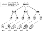
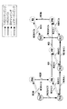
図4Aは、ネットワークNAA、NCCおよびNEEからなるネットワークNAAA(d, n, h+2)を(d, n, h+1)で示す。 FIG. 4A shows a network NAAA (d, n, h + 2) composed of networks NAA, NCC and NEE by (d, n, h + 1).
ネットワークNAAは、(d, n, h)のネットワークNAおよびNBからなる。
ネットワークNCCは、(d, n, h)のネットワークNCとNDで構成されます。
ネットワークNEEは、(d, n, h)のネットワークNEおよびNFからなる。図4Aはまた、(d, n, h)におけるネットワーク間のトポロジマッピングを示す。図4Bは、図4AのネットワークNAAA、NAA、NCC、NEE、NA、NB、NC、ND、NEおよびNFのセットの代替表現を示し、(d = 1、n = 0 )。 一例として、(d=1, n=0, h=2)のネットワークNAAAは、(d=1, n=0, h=1)のネットワークNAA、
NCCおよびNEEからなる。したがって、ネットワークNAAAとネットワークNAAとの間にレベルマッピングが示され、ネットワークNAAAとネットワークNCCとの間にレベルマッピングが示され、ネットワークNAAAとネットワークNEEとの間にレベルマッピングが示される。このように、階層グラフである階層ネットワークは、非階層グラフとして表されることに留意されたい。第1のネットワークから第2のネットワークへのトポロジマッピング、レイヤマッピング、深度マッピングまたはレベルマッピングは、1:1,1:nまたはn:1マッピング(第1のネットワーク:第2のネットワーク)とすることができる(PCT / EP2014 / 055640の96ページ参照)。
提案されたアプローチをスケーラブルにするために、以下の形式のネットワークおよびノードの論理的命名における階層を導入する(PCT / EP2014 / 055640ページ80参照):
。 。 。 。 。 ネットワーク・オブ・ネットワーク・オブ・ネットワーク
。ネットワーク・オブ・ネットワーク 。ネットワーク 。ノード
ドット記号 "。"は、論理名が構成するさまざまな要素を区切ります。
私たちはNoNoNs (Network-of-Networks-of-Networks)としてネットワークオブネットワークオブネットワークを参照します、NoNs (Network-of-Networks)としてのネットワーク・オブ・ネットワークを参照してください。上記の命名構造は階層を再帰的に導入します:
- ネットワークは、ノードの集合です
- NoNsはネットワークの集合です
- NoNoNsはNoNsのコレクションです
- 上記の使用された命名フォームの定義で「....」と示されているように。
これにより、ネットワーク内に任意の数の階層レベルが作成されます。実際には、実際の制約に限定されています。
上記の構造を使用すると、ノードは次のように配置されます:
。 。 。 。 。ネットワーク・オブ・ネットワーク・オブ・ネットワーク。 ネットワークオブネットワーク。 ネットワーク。 ノード
同様に、ネットワークは次の場所にあります:
。 。 。 。 。ネットワーク・オブ・ネットワーク・オブ・ネットワーク。 ネットワークオブネットワーク。 ネットワーク
同様に、NoNsは次の場所に配置されます:
。 。 。 。 。ネットワーク・オブ・ネットワーク・オブ・ネットワーク。 ネットワーク・オブ・ネットワーク
階層内のさまざまなレベルについても同様です。
各ドット記号「。」はレベルマッピング(PCT / EP2014 / 055640の119ページ参照)を表しているので、アドレス構造はレベルマッピングによって表されるネットワークの階層構造に厳密に従う。物理的なネットワーク内では、階層的な命名も使用できることに注意してください。
ここで、アドレスを次の形式に拡張します:
。 。 。 。 。ネットワーク・オブ・ネットワーク・オブ・ネットワーク。 ネットワークオブネットワーク。 ネットワーク。 ノード。 サブ識別子1。 サブ識別子2。 。 。 。 。
「。 。 。 。 。 ネットワーク・オブ・ネットワーク・オブ・ネットワーク。 ネットワークオブネットワーク。 ネットワーク」内の各ドット記号「。」はレベルマッピングを表し、「ノード。 サブ識別子1。 サブ識別子2。 。 。 。 。」内の各ドット記号「。」はレイヤーマッピングを表す。"。 。 。 。 「ネットワーク・オブ・ネットワーク・オブ・ネットワーク」の前に、階層命名を任意の数のレベルに拡張できることが識別されます。「サブ識別子2」の後の「。 。 。 。」は、
アドレスが任意の数の層を含むことができることを識別する。サブ識別子はノードです。層nのサブ識別子は、層(n + 1)へのサービスを提供する。
The network NAA includes (d, n, h) networks NA and NB.
Network NCC consists of (d, n, h) network NC and ND.
The network NEE consists of (d, n, h) networks NE and NF. FIG. 4A also shows topology mapping between networks at (d, n, h). FIG. 4B shows an alternative representation of the set of networks NAAA, NAA, NCC, NEE, NA, NB, NC, ND, NE and NF of FIG. 4A (d = 1, n = 0). As an example, the network NAAA of (d = 1, n = 0, h = 2) is the network NAA of (d = 1, n = 0, h = 1),
Consists of NCC and NEE. Therefore, level mapping is shown between network NAAA and network NAA, level mapping is shown between network NAAA and network NCC, and level mapping is shown between network NAAA and network NEE. Thus, it should be noted that a hierarchical network that is a hierarchical graph is represented as a non-hierarchical graph. Topology mapping, layer mapping, depth mapping or level mapping from the first network to the second network shall be 1: 1, 1: n or n: 1 mapping (first network: second network) (Refer to page 96 of PCT / EP2014 / 055640).
In order to make the proposed approach scalable, we introduce a hierarchy in the logical naming of networks and nodes of the following form (see PCT / EP2014 / 0555640 page 80):
. . . . . Network of network of network. Network of network. Network. node
The dot symbol "." Separates the various elements that a logical name comprises.
We refer to Network of Network of Network as NoNoNs (Network-of-Networks), see Network of Network as NoNs (Network-of-Networks). The above naming structure introduces the hierarchy recursively:
-A network is a collection of nodes
-NoNs is a collection of networks
-NoNoNs is a collection of NoNs
-As indicated by "...." in the used naming form definition above.
This creates any number of hierarchy levels in the network. In practice, it is limited to actual constraints.
Using the above structure, the nodes are arranged as follows:
. . . . . Network of network of network. Network of network. network. node
Similarly, the network is at:
. . . . . Network of network of network. Network of network. Like the network, NoNs are located at:
. . . . . Network of network of network. The same is true for the various levels in the network of network hierarchy.
Since each dot symbol “.” Represents a level mapping (see page 119 of PCT / EP2014 / 0555640), the address structure strictly follows the network hierarchy represented by the level mapping. Note that hierarchical naming can also be used within a physical network.
Now expand the address to the following format:
. . . . . Network of network of network. Network of network. network. node. Sub-identifier 1. Sub-identifier 2. . . . .
Each dot symbol “.” In “Network of network. Network of network. Network” represents a level mapping, and “Node. Sub-identifier 1. Sub-identifier 2. Each dot symbol “.” In “.” Represents layer mapping. "..." Before "Network of Network of Network", it is identified that hierarchical naming can be extended to any number of levels. “...” after “Sub-identifier 2”
Identifies that an address can contain any number of layers. The sub-identifier is a node. The sub-identifier of layer n provides service to layer (n + 1).
このようなサービスに限定されるものではないが、一例として、多重化サービスがある。このアプローチを使用すると、さまざまなレイヤーの論理名を1つの論理アドレス空間にまとめることができます。これにより、複数のレイヤにまたがる論理アドレス空間を使用して転送を実行することが可能になります。これは、ノードを階層的なネットワーク内でそのアドレスを突き止める手段を提供する。さらに、上記のアプローチは、すべてのネットワークを命名階層内の特定のレベルのノードに抽象化する。たとえば、NoNsは、ネットワークがノード間の隣接関係を持つノードの集合で構成されるのと同じ方法で、ネットワーク間の隣接関係を持つネットワークの集合で構成されます。
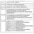
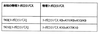
トポロジー・パスは、トポロジマッピングの連結です(PCT / EP2014 / 055640の174ページを参照)。第1のトポロジパスは、第1のトポロジパスと第2のトポロジパスの入れ子を作成する第2のトポロジパスからなることができる。トポロジパスは、次の方法で作成できます:(d、n、h)での0以上のトポロジマッピングと(d、n、h)での0以上のトポロジパスの連結として、(d、n、h)での第1のネットワークから(d、n、h)での第2のネットワークへのトポロジパスを計算して記憶するステップであって、前記トポロジマッピングの数および前記トポロジパスの数は、合計は少なくとも1つです。この方法は、トポロジパスを計算する方法と呼ばれます。 (PCT / EP2014 / 055640の181,182頁参照)。1つのトポロジマッピングの連結は、(d、n、h)の第1のネットワークから(d、n、h)の第2のネットワークへの前記トポロジパスが、単一のトポロジマッピング 。説明を比較的簡単にするために、「1の連結」という用語は、ORステートメントを避けるために使用されます。
レベルパスをレベル・マッピングの連結として定義する(PCT / EP2014 / 055640の146ページ参照)、第1のレベルパスは、第1のレベルパスと第2のレベルパスのネストを作成する第2のレベルパスを含むことができる(PCT / EP2014 / 055640ページ174参照)。次の方法を使用してレベルパスを作成できます:
(d、n)での0以上のレベルマッピングと(d、n)での0以上のレベルパスの連結として、(d、n、h1)の第1のネットワークから(d、n、h2)の第2のネットワークへのレベルパスを計算して記憶するステップであって、前記レベルマッピングの数および前記レベルパスの数は、 合計は少なくとも1つです。
この方法は、レベルパスを計算する方法と呼ばれます。我々は、転送エントリが要求されたレベルパスとしてユーザによって要求されるレベルパスを参照する。
1つまたは複数のトポロジパスおよび1つまたは複数のレベルパスを連結することができるので、(d、n、h1)の第1のネットワークから(d、n、h2)の第2のネットワークへのトポロジーレベルパス (d、n)における0以上のトポロジパスと(d、n)における0以上のレベルパスと(d、n)におけるゼロ以上のトポロジーレベルパスとの連結として定義される。前記トポロジパスの数および前記レベルパスの数および前記トポロジ・レベルパスの数は、それらの和が少なくとも1つであるような数である、請求項1に記載の方法。この方法は、トポロジーレベルパスを計算する方法と呼ばれます。第1のトポロジー・レベルパスは、第1のトポロジー・レベルパスと第2のトポロジー・レベルパスの入れ子を作成する第2のトポロジー・レベルパスを含むことができることに留意されたい。トポロジ・レベルのパスは、単一のトポロジパスでも、単一のレベルパスでもかまいません。
Although not limited to such a service, an example is a multiplexing service. Using this approach, you can combine logical names from different layers into a single logical address space. This makes it possible to perform transfers using a logical address space that spans multiple layers. This provides a means of locating a node in a hierarchical network. Furthermore, the above approach abstracts all networks to a specific level of nodes in the naming hierarchy. For example, NoNs consists of a set of networks with adjacencies between networks in the same way that a network consists of a set of nodes with adjacencies between nodes.
A topology path is a concatenation of topology mappings (see page 174 of PCT / EP2014 / 0555640). The first topology path can consist of a second topology path that creates a nesting of the first topology path and the second topology path. Topology paths can be created in the following ways: (d, n, h) as a concatenation of zero or more topology mappings at (d, n, h) and zero or more topology paths at (d, n, h) calculating and storing a topology path from the first network in h) to the second network in (d, n, h), wherein the number of topology mappings and the number of topology paths are: The total is at least one. This method is called calculating the topology path. (See pages 181, 182 of PCT / EP2014 / 055640). The concatenation of one topology mapping is a single topology mapping where the topology path from the first network of (d, n, h) to the second network of (d, n, h). For ease of explanation, the term “concatenation of 1” is used to avoid OR statements.
Define the level path as a concatenation of level mappings (see page 146 of PCT / EP2014 / 0555640), the first level path is the second level that creates a nesting of the first level path and the second level path The path can be included (see PCT / EP2014 / 0555640 page 174). You can create a level path using the following methods:
As a concatenation of zero or more level mappings at (d, n) and zero or more level paths at (d, n), from the first network of (d, n, h1) to (d, n, h2) Calculating and storing a level path to the second network, the number of level mappings and the number of level paths being at least one in total.
This method is called the level path calculation method. We refer to the level path requested by the user as the level path for which the forwarding entry was requested.
Since one or more topology paths and one or more level paths can be concatenated, from (d, n, h1) first network to (d, n, h2) second network Topology level path Defined as a link between zero or more topology paths in (d, n), zero or more level paths in (d, n), and zero or more topology level paths in (d, n). 2. The method of
フォワーディングエントリが要求されたトポロジパス、要求されたレベルパス、および要求されたトポロジーレベルパスとしてそれぞれ要求されるトポロジパス、レベルパスおよびトポロジーレベルパスを参照する(PCT / EP2014 / 055640 ページ182)。 The topology path for which the forwarding entry is requested, the requested level path, and the requested topology path as the requested topology level path, refer to the requested topology path, level path, and topology level path, respectively (PCT / EP2014 / 055640 page 182).
一例として、限定されないが、要求されたトポロジパスは、SDNコントローラ、物理ノード、SDNコンパイラのユーザによって要求される可能性がある。そのような要求は、予防的な経路 - インスタンス化または反応的な経路 - インスタンス化であり得る。トポロジマッピング、深度マッピング、レイヤーマッピング、レベルマッピング、トポロジパス、レベルパス、トポロジーレベルパスをエッジと呼びます。
一例として、トポロジーレベルのパスは、単一のトポロジパス、単一のレベルパス、単一のトポロジマッピング、または単一のレベルマッピングを含むことができるが、これに限定されないことに留意されたい。
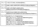
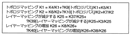
トポロジマッピングは、次のいずれかの方法を使用して作成できます:
トポロジマッピングを計算するための第1の方法であって、以下の動作を含む:
前記第1のネットワークから(d-x, n2, h)の第3のネットワークへの深さマッピング、前記第3のネットワークから(d-x, n2, h)の第4のネットワークへのトポロジーレベルパスおよび前記第4のネットワークから前記第2のネットワークへの深さマッピングの連結として、(d、n1、h)の第1のネットワークから(d、n1、h)の第2のネットワークへのトポロジマッピングを計算して記憶する、xが0より大きくd以下であり、 ここで、n1はn2に等しくてもよい。
トポロジマッピングを計算するための第2の方法であって、以下の動作を含む:
前記第1のネットワークから(d, n-y, h)の第3のネットワークへのレイヤーマッピング、前記第3のネットワークから(d, n-y, h)の第4のネットワークへのトポロジーレベルパスおよび前記第4のネットワークから前記第2のネットワークへのレイヤーマッピングの連結として、(d、n、h)の第1のネットワークから(d、n、h)の第2のネットワークへのトポロジマッピングを計算して記憶する、yが0より大きくn-n_min(d)以下であり、n_min(d)は特定の深度dで最下位層であり、n_min(d)は=> 0である 。
トポロジマッピングを計算する第3の方法であって、以下の動作を含む:
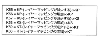
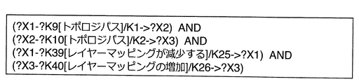
前記第1のネットワークから(d, n, h-z)の第3のネットワークへのレベルが減少する1つまたは複数のレベルマッピング、前記第3のネットワークから(d, n, h-z)の第4のネットワークへのトポロジーレベルパスおよび前記第4のネットワークから前記第2のネットワークへのレベルが増加する1つまたは複数のレベルマッピング
の連結として、(d、n、h)の第1のネットワークから(d、n、h)の第2のネットワークへのトポロジマッピングを計算して記憶する、zが0より大きくh-h_min以下であり、h_minは深度dとレイヤnで最低レベルです 。
トポロジマッピングを計算するための第1の方法および第2の方法で使用されるトポロジー・レベルパスは、トポロジー・レベルパス、トポロジー・パスまたはレベルパストポロジー・パスとトポロジー・レベルパスは、単一のレベルパスで構成できます。トポロジマッピングの作成時に、トポロジマッピングの計算に使用されるトポロジレベルパスは、明示的に作成されたトポロジレベルパスまたはトポロジマッピングとレベルマッピングの連結であるパスのいずれかです。
By way of example and not limitation, the requested topology path may be requested by a user of the SDN controller, physical node, or SDN compiler. Such a request can be a proactive path-instancing or a reactive path-instancing. Topology mapping, depth mapping, layer mapping, level mapping, topology path, level path, and topology level path are called edges.
By way of example, it should be noted that a topology level path can include, but is not limited to, a single topology path, a single level path, a single topology mapping, or a single level mapping.
You can create a topology mapping using one of the following methods:
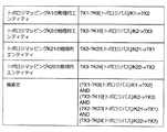
A first method for calculating topology mapping, which includes the following operations:
Depth mapping from the first network to a third network of (dx, n2, h), a topology level path from the third network to a fourth network of (dx, n2, h), and the second Calculate the topology mapping from the first network of (d, n1, h) to the second network of (d, n1, h) as a concatenation of depth mapping from the four networks to the second network X is greater than 0 and less than or equal to d, where n1 may be equal to n2.
A second method for calculating the topology mapping, which includes the following operations:
Layer mapping from the first network to a third network of (d, ny, h), topology level path from the third network to a fourth network of (d, ny, h) and the fourth Calculate and store the topology mapping from the first network (d, n, h) to the second network (d, n, h) as the concatenation of the layer mapping from the second network to the second network Y is greater than 0 and less than or equal to n-n_min (d), n_min (d) is the lowest layer at a specific depth d, and n_min (d) is => 0.
A third method for calculating the topology mapping, which includes the following operations:
One or more level mappings with decreasing levels from the first network to the third network of (d, n, hz), the fourth network of (d, n, hz) from the third network From the first network of (d, n, h) as (d, n, h) as a concatenation of the topological level path and one or more level mappings of increasing levels from the fourth network to the second network Calculate and store the topology mapping of n, h) to the second network, where z is greater than 0 and less than or equal to h-h_min, h_min is the lowest level at depth d and layer n.
The topology level path used in the first and second methods for calculating the topology mapping is topology level path, topology path or level path topology path and topology level path is a single Can be configured with level path. When creating a topology mapping, the topology level path used to calculate the topology mapping is either an explicitly created topology level path or a path that is a concatenation of the topology mapping and level mapping.
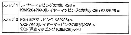
レイヤマッピングは、次のいずれかの方法を使用して作成できます:
以下の動作を含むレイヤマッピングを計算するための第1の方法:
前記第1のネットワークから(d-x, n2, h)の第3のネットワークへの深さマッピング、前記第3のネットワークから(d-x, n2-y, h)の第4のネットワークへの0以上のレイヤーマッピングよび前記第4のネットワークから前記第2のネットワークへの深さマッピングの連結として、(d、n1、h)の第1のネットワークから(d、n1-y、h)の第2のネットワークへのレイヤーマッピングを計算して記憶する、xが0より大きくd以下であり、yが0より大きくかつn1-n1_minより小さくかつn2-n2_min以下であり、n1_minは深度dで最下位層であり、n2_minは深度d-xで最下位層である。
レイヤマッピングを計算する第2の方法であって、以下の動作を含む:
前記第1のネットワークから(d-x, n2, h)の第3のネットワークへの深さマッピング、前記第3のネットワークから(d-x, n2+y, h)の第4のネットワークへの0以上のレイヤーマッピングよび前記第4のネットワークから前記第2のネットワークへの深さマッピングの連結として、(d、n1、h)の第1のネットワークから(d、n1+y、h)の第2のネットワークへのレイヤーマッピングを計算して記憶する、xが0より大きくd以下であり、yが0より大きくかつn1_max-n1より小さくかつn2_max-n2以下であり、n1_maxは深さdで最高の層であり、n2_maxは深さd-xで最高の層である。
レイヤマッピングを計算するための第1の方法では、第3および第4のネットワークは、(d-x, n2, h)または(d-x, n2-y, h)の同じネットワークとすることができることに留意されたい。 レイヤマッピングを計算する第2の方法では、第3および第4のネットワークは、(d-x, n2, h)または(d-x, n2+y, h)の同じネットワークとすることができることに留意されたい。
You can create a layer mapping using one of the following methods:
A first method for calculating a layer mapping that includes the following actions:
Depth mapping from the first network to the third network of (dx, n2, h), zero or more layers from the third network to the fourth network of (dx, n2-y, h) As a mapping and concatenation of depth mapping from the fourth network to the second network, from the first network of (d, n1, h) to the second network of (d, n1-y, h) X is greater than 0 and less than or equal to d, y is greater than 0 and less than n1-n1_min and less than or equal to n2-n2_min, n1_min is the lowest layer at depth d, n2_min is the lowest layer at the depth dx.
A second method for calculating layer mapping, which includes the following operations:
Depth mapping from the first network to the third network of (dx, n2, h), zero or more layers from the third network to the fourth network of (dx, n2 + y, h) As a concatenation of mapping and depth mapping from the fourth network to the second network, from the first network of (d, n1, h) to the second network of (d, n1 + y, h) Calculate and store the layer mapping of x, where x is greater than 0 and less than or equal to d, y is greater than 0 and less than n1_max-n1, and less than or equal to n2_max-n2, n1_max is the highest layer at depth d , N2_max is the highest layer at depth dx.
Note that in the first method for calculating layer mapping, the third and fourth networks can be the same network of (dx, n2, h) or (dx, n2-y, h) I want. Note that in the second method of calculating layer mapping, the third and fourth networks can be the same network of (dx, n2, h) or (dx, n2 + y, h).
レイヤnの第1のノードからレイヤ(n-1)の第2のノードへのレイヤマッピング後にトポロジマッピングが行われると、ノードKAのような多重化アクションが生じる(例えば、 PCT / EP2014 / 055640ページ236)。したがって、SDNコンパイラは、機器レベルではなくコンポーネントレベルで転送エントリを提供するときに、物理ノードの多重化および逆多重化機能を認識する必要があります。一例として、要素管理システム(EMS)によって多重化および逆多重化機能をSDNコンパイラに提供することができるが、これに限定されない。
各エッジの名前をつけ、マッピングおよびトポロジーレベルパスを示すために図6A〜6Dに示す表記を使用する(PCT / EP2014 / 055640図51A〜51D、182ページ参照)。図6Aは、第1のエッジ名を有する第1のマッピングに使用される表記を示し、第1のマッピングは第1のマッピング・タイプであり、第1のマッピング・タイプはトポロジマッピング、深度マッピング、レイヤーマッピングまたはレベル・マッピングである 第1のネットワークを第2のネットワークに接続する。第1のアタッチメントポイント (Point-of-Attachment)(PoA)における第1のネットワークおよび第1のマッピング・インターフェース、第2のPoAにおける第2のネットワークおよび第1のマッピング・インターフェース。第1のPoAおよび第2のPoAはオプションである。 マッピングの方向を示す ' - () - >'記号。
上記の図3Cに示すネットワークKA、KB、KC、KD、LA、LB、LC、LDおよびネットワークKAとネットワークとの間のトポロジマッピングを示す図5Aの例によるエッジおよび表記の命名を説明する。 KB、ネットワークKAとネットワークKCとの間のレイヤーマッピング、およびネットワークKBとネットワークKDとの間のレイヤーマッピング。図5Aはまた、ポイントオブアタッチメント(PoAs)p701からp706を示す。
ネットワークKA、KB、KCおよびKDは物理ネットワークであるため、ネットワークKAとネットワークKBとの間のトポロジマッピングは物理リンクを表し、ネットワークKAとネットワークKCとの間のレイヤマッピングは物理リンクを表し、 ネットワークKBおよびネットワークKDは、物理リンクを表している。物理リンクは一方向または双方向であり得るため、第1のネットワークから第2のネットワークへのトポロジマッピング、深度マッピング、レイヤマッピング、レベルマッピング、トポロジパス、レベルパスまたはトポロジレベルパスを表す。 グラフ内の有向枝によって第2のネットワークに接続される。
これは図5Bに示され、ネットワークKA、KB、KC、KD、LA、LB、LC、LD、トポロジマッピング、レイヤーマッピング、および深さマッピングを示す。図7Aは、図6Aの表記における図5Bのマッピングを示す。一例として、ネットワークKAからネットワークKBへのL5という名前のトポロジマッピングはで表される:L5=KA-(トポロジマッピング p701::p702)->KB、ここで、「トポロジマッピング」は「トポロジマッピング」を指します。 同様に、「深さマッピング」は「深度マッピング」を、「レイヤーマッピング」は「レイヤーマッピング」を、「レベルマッピング」は「レベルマッピング」を、「トポロジパス」は「トポロジパス」を、「レベルパス」は 使用されている表記法の 'レベルパス'に変換されます。任意選択的に、深度マッピング、レイヤーマッピング、およびレベルマッピングの方向をマッピングタイプに含めることができる(PCT / EP2014 / 055640ページ180参照)。
図6Aと同じ表記を使用して、図6Bは、第2のエッジ名を有する第2のマッピングを示し、第2のマッピングは、第2のネットワークから第3のネットワークへの第2のマッピングタイプである。図5Cに示すように、上述のトポロジマッピングを計算するための第1の方法を適用することによって、ネットワークLAからネットワークLBへのL14という名前のトポロジマッピングを計算して格納し、ネットワークLAからネットワークKAへのL12という深さマッピングの連結として、ネットワークKAネットワークKBからのL11という名前のトポロジパス、ネットワークKBからネットワークLBへのL13という名前の深度マッピングと、ネットワークKAからネットワークKBへのL11という名前のトポロジパスは、ネットワークKAからネットワークKBへのL5という名前の単一のトポロジマッピングを含む。
When topology mapping is performed after layer mapping from the first node of layer n to the second node of layer (n-1), a multiplexing action like node KA occurs (eg, PCT / EP2014 / 055640 page 236). Therefore, the SDN compiler needs to be aware of the multiplexing and demultiplexing capabilities of the physical node when providing forwarding entries at the component level rather than the equipment level. As an example, an element management system (EMS) can provide multiplexing and demultiplexing functions to an SDN compiler, but is not limited thereto.
Use the notation shown in FIGS. 6A-6D to name each edge and indicate the mapping and topology level path (see PCT / EP2014 / 0555640 FIGS. 51A-51D, page 182). FIG. 6A shows the notation used for the first mapping with the first edge name, where the first mapping is the first mapping type, and the first mapping type is topology mapping, depth mapping, Connect the first network, which is layer mapping or level mapping, to the second network. A first network and a first mapping interface at a first point-of-attachment (PoA), a second network and a first mapping interface at a second PoA. The first PoA and the second PoA are optional. A '-()->' sign indicating the direction of the mapping.
Edge and notation naming according to the example of FIG. 5A showing the topology mapping between the networks KA, KB, KC, KD, LA, LB, LC, LD and the network KA and the network shown in FIG. Layer mapping between KB, network KA and network KC, and layer mapping between network KB and network KD. FIG. 5A also shows point of attachment (PoAs) p701 to p706.
Since networks KA, KB, KC and KD are physical networks, the topology mapping between network KA and network KB represents a physical link, and the layer mapping between network KA and network KC represents a physical link. KB and network KD represent physical links. Since a physical link can be unidirectional or bidirectional, it represents a topology mapping, depth mapping, layer mapping, level mapping, topology path, level path, or topology level path from a first network to a second network. Connected to the second network by a directed edge in the graph.
This is shown in FIG. 5B and shows networks KA, KB, KC, KD, LA, LB, LC, LD, topology mapping, layer mapping, and depth mapping. FIG. 7A shows the mapping of FIG. 5B in the notation of FIG. 6A. As an example, a topology mapping named L5 from network KA to network KB is represented by: L5 = KA- (topology mapping p701 :: p702)-> KB, where “topology mapping” is “topology mapping” Refers to. Similarly, “depth mapping” is “depth mapping”, “layer mapping” is “layer mapping”, “level mapping” is “level mapping”, “topology path” is “topology path”, “level” "Path" is converted to the 'level path' of the notation used. Optionally, the direction of depth mapping, layer mapping, and level mapping can be included in the mapping type (see PCT / EP2014 / 0555640 page 180).
Using the same notation as in FIG. 6A, FIG. 6B shows the second mapping with the second edge name, the second mapping is the second mapping type from the second network to the third network It is. Calculate and store the topology mapping named L14 from network LA to network LB by applying the first method for calculating topology mapping described above, as shown in Figure 5C, and network from network LA to network LB As a concatenation of depth mapping L12 to KA, a topology path named L11 from network KA network KB, depth mapping named L13 from network KB to network LB, and name L11 from network KA to network KB The topology path includes a single topology mapping named L5 from network KA to network KB.
あるいは、L11という名前のトポロジー・パスの作成も省略でき、L14という名前のトポロジマッピングは、トポロジマッピングL5から直接作成できました。図5Cにおいて、ネットワークKAからネットワークKBへのL5という名前のトポロジマッピングは、トポロジマッピングL5がトポロジパスL11を計算するために使用されることを示すL5 / L11でラベル付けされている。 言い換えれば、トポロジパスL11は、トポロジマッピングL5にマッピングされる。
2つのエッジ間の関係は、第2のエッジが第1のエッジに多重化またはマッピングされ、「第1のエッジ/第2のエッジ」によってフォワードスラッシュ記号を使用してそのようなエッジ関係を表すエッジ関係として参照されます。一例として、図5Cに示すようなL5 / L11を、エッジ名L5によって示されるトポロジマッピングとエッジ名L11によって示されるトポロジパスとの間のエッジ関係として参照し、ここではL11と名付けられたトポロジパスがマップされる L5という名前のトポロジマッピングに変換します、言い換えれば、トポロジマッピングL5がトポロジパスL11を計算するために使用される。図5Cでは、そのようなエッジをラベリングするときに、エッジの名前が太字で示されている。
図6Cは、第3のエッジ名を有する第3のエッジの表記を示し、第3のエッジは第3のエッジタイプであり、第1のエッジと第2のエッジの連結であり、プラス記号は連結を示し、前方スラッシュ記号 エッジ関係を表す。例として、図7Bは、図6Cの表記を使用して、L14という名前のトポロジマッピングを「トポロジマッピング L14 = L12/L14+L11/L14+L13/L14」として作成し、L11という名前のトポロジパスを「トポロジパスL11 = L5/L11」として作成することを示す。
図5Dに示すように、レイヤマッピングを計算するための第1の方法および第2の方法を適用することによって、ネットワークLCからネットワークLAへのレイヤマッピングL19を計算し、ネットワークLCからネットワークKCへのL17という名前の深さマッピング ネットワークKCネットワークKAからのL7という名前のレイヤーマッピングと、ネットワークKAからネットワークLAへのL15という深さマッピングとを含む。そして、ネットワークLBからネットワークLDへのレイヤーマッピングL20を計算し、ネットワークLBからネットワークKBへのL16という名前の深さマッピングと、ネットワークKBからネットワークKDへのL10という名前のレイヤーマッピングと深度 ネットワークKDからネットワークLDにL18という名前のマッピング。
Alternatively, creating a topology path named L11 could be omitted, and a topology mapping named L14 could be created directly from topology mapping L5. In FIG. 5C, the topology mapping named L5 from network KA to network KB is labeled with L5 / L11 indicating that topology mapping L5 is used to compute topology path L11. In other words, the topology path L11 is mapped to the topology mapping L5.
The relationship between two edges represents such an edge relationship with the second edge multiplexed or mapped to the first edge and using a forward slash symbol by "first edge / second edge" It is referred to as an edge relationship. As an example, refer to L5 / L11 as shown in Figure 5C as the edge relationship between the topology mapping indicated by edge name L5 and the topology path indicated by edge name L11, here the topology path named L11 Translates to a topology mapping named L5 that is mapped, in other words, topology mapping L5 is used to calculate the topology path L11. In FIG. 5C, when labeling such an edge, the name of the edge is shown in bold.
FIG. 6C shows a representation of a third edge with a third edge name, where the third edge is the third edge type, the first edge is connected to the second edge, and the plus sign is Indicates concatenation and forward slash symbol indicates edge relation. As an example, Figure 7B uses the notation of Figure 6C to create a topology mapping named L14 as "Topology Mapping L14 = L12 / L14 + L11 / L14 + L13 / L14" and a topology path named L11 Is created as “topology path L11 = L5 / L11”.
As shown in FIG. 5D, by applying the first and second methods for calculating the layer mapping, the layer mapping L19 from the network LC to the network LA is calculated and the network LC to the network KC is calculated. Depth mapping named L17 Includes layer mapping named L7 from network KC network KA and depth mapping L15 from network KA to network LA. Then calculate layer mapping L20 from network LB to network LD, depth mapping named L16 from network LB to network KB, layer mapping named L10 from network KB to network KD and depth from network KD Mapping named L18 to network LD.
図5Eに示されるように、トポロジマッピングを計算するための第2の方法を適用することにより、ネットワークLCからネットワークLDへのL22という名前のトポロジマッピングを、ネットワークLCからネットワークLAへのレイヤマッピングL19の連結として計算して記憶する ネットワークLAネットワークLBからのL21という名前のトポロジパスと、ネットワークLBからネットワークLDへのL20という名前のレイヤーマッピングとを含む。ネットワークLAからネットワークLBへのL21という名前のトポロジパスは、ネットワークLAからネットワークLBへのL14という名前の単一のトポロジ・マッピングから成る。 As shown in FIG. 5E, by applying the second method for calculating the topology mapping, the topology mapping named L22 from the network LC to the network LD is converted into the layer mapping L19 from the network LC to the network LA. The network LA includes a topology path named L21 from the network LB and a layer mapping named L20 from the network LB to the network LD. The topology path named L21 from network LA to network LB consists of a single topology mapping named L14 from network LA to network LB.
図5Fに示すように、ネットワークLCからネットワークLDまでのL22という名前の単一のトポロジマッピングとして、ネットワークLCからネットワークLDへのL23という名前のトポロジパスを計算して格納する。
図7Bは、図6Cの表記を使用するトポロジパスL11、L21およびL23、トポロジマッピングL14およびL22、ならびにレイヤマッピングL19およびL20の作成を示す。 図5Fに示すエッジ関係は、再帰を介してエッジ関係の集合を計算するために使用することができる。ここで、「再帰」という用語は、数学的再帰操作を指す。 前記エッジ関係のセットは、ネストされたエッジ関係からなる。ここで、「ネストされたエッジ関係」における「ネスト」という用語は、数学的にネストされた形式を有するエッジ関係を指す。
一例として、ネットワークKAからネットワークKBへのトポロジマッピングはエッジ関係L5 / L11を有し、ネットワークKAからネットワークKBへのトポロジパスはエッジ関係L11 / L14、ネットワークからのトポロジマッピング LAからネットワークLBへのエッジ関係L14 / L21、ネットワークLAからネットワークLBへのトポロジパスはエッジ関係L21 / L22、ネットワークLCからネットワークLDへのトポロジマッピングはエッジ関係L22 / L23、トポロジ ネットワークLCからネットワークLDへのパスは名前L23を有するため、ネットワークKAからネットワークKBへのL11という名前のトポロジマッピングは、エッジ関係L5 / L11 / L14 / L21 / L22 / L23の例セットを有する。単一のエッジ関係と、エッジ関係の集合として再帰を組み合わせた2つ以上のエッジ関係を参照します。第1の例は、L5と命名されたトポロジマッピングのエッジ関係の組の限定ではないが、L5 / L11 / L14 / L21 / L22 / L23である。 第2の例は、L5と名付けられたトポロジマッピングのエッジ関係のセットのうちのL5 / L14 / L23であるが、これに限定されない。
エッジ関係のセットにおける最初のエッジ名は前記エッジの名前であることに留意されたい。 再帰を介して要求されたトポロジパスL23の再帰パスを計算し、各エッジのエッジ関係の集合に入れ子になったエッジ関係を格納する。ここで、再帰パスは、数学的手法として再帰を使用して計算されるパスとして定義されます。再帰的パスの例は、図5FのL23である。
図7Cは、ネットワークLCからネットワークLDへのL23という名前のトポロジパスの再帰パスの計算を示す。図5Fに示されるように、上記では、ネットワークLCからネットワークLDへのL22という名前の単一トポロジマッピングとして、ネットワークLCからネットワークLDへのL23という名前のトポロジパスを計算して格納し、図7BのL23という名前のトポロジパスを 上記の表記に従って、ステップ1に示されている「トポロジパスL23 = L22/L23」。図7Bに示す関係を使用して、図7Cのステップ5に示すように、再帰パスと各エッジのネストされたエッジ関係を含むエッジ関係の集合を再帰的に計算する。図7Cのステップ2〜4は、計算の中間ステップである。図6Dには、図6A、図6Bおよび図6Cの表記を使用して、トポロジパス、レベルパスまたはトポロジーレベルパスの表記が示されている。図7Cのステップ6では、図7Cのステップ5を図7Aと組み合わせることによって、図6Dの表記を使用して、ステップ5の再帰パスが示される。
ここでは、一連の階層型ネットワークにエッジの名前を付けることにします。 図8は、ネットワークNAAA、NAA、NCC、NEE、NA、NB、NC、ND、NE、NF、QA、QB、QC、QD、QE、QFおよび(d=0, n=0, h=0)におけるトポロジマッピング、 (d=1, n=0, h=0)および深度マッピングは、図4Aおよび図4Bに示すネットワークの有向枝を用いた表現である。ネットワークNAAとネットワークNAAAとの間のレベルマッピングなどであるがこれに限定されないレベルhの第1のネットワークとレベルh + 1の第2のネットワークとの間の関係である図4Bのレベルマッピングはそれぞれ、ネットワークNAAからネットワークNAAAへのレベルマッピングおよびネットワークNAAAからネットワークNAAへのレベルマッピングのような、限定されるものではないが有向エッジである一対のレベルマッピングがある。ネットワークNAAからネットワークNAAAへのレベルマッピングはJ22と命名され、図8に示されている。ネットワークNAAAからネットワークNAAへのレベルマッピングはJ47と命名され、図8に示されている。
PCT / EP2014 / 055640(図53E)は、図6Aの記法による物理トポロジマッピング、深さマッピングおよびレベルマッピングを説明している。図8に示すように、ネットワークNAAからネットワークNCCへのJ30という名前のトポロジマッピングを、ネットワークNAAからネットワークNBへのレベルマッピングJ17と、ネットワークNBネットワークNCからのJ29という名前のトポロジパスと、 ネットワークNCからネットワークNCCへのJ18という名前のレベルマッピング。ネットワークNBからネットワークNCへのJ29という名前のトポロジパスは、上述したトポロジマッピングを計算する第3の方法を使用して、ネットワークNBからネットワークNCへのJ25という名前の単一のトポロジマッピングを含む。ネットワークNCCからネットワークNDへのレベルマッピングJ19、ネットワークNDネットワークへのJ27という名前のトポロジマッピング、およびネットワークNDNからのレベルマッピングの結合として、ネットワークNCCからネットワークNEEへのJ31という名前のトポロジマッピングを計算して保存します。J20をネットワークNEからネットワークNEEに送信し、上述したトポロジマッピングの計算の第3の方法を使用している。J30およびJ31という名前のトポロジマッピングを作成することにより、ノードNAA、NCC、およびNEE間の転送動作を指定できます。当業者には理解されるように、トポロジマッピングの作成は、任意の数の階層レベルで繰り返すことができる。 PCT / EP2014 / 055640(ページ 213)は、レベルパスがどのようにトポロジパスに変更されるかを記述する。
パケット交換ノードを含むパケット交換ネットワーク(Packet Switched Network:PSN)においてパケット転送またはスイッチングを可能にするため、または非パケット交換ネットワークにおいて物理信号の中継またはスイッチングを可能にするために、上記では、0または1つのスイッチング識別子 トポロジマッピング、トポロジー・パス、レベルパス、およびトポロジー・レベルパスが含まれます。 (PCT / EP2014 / 055640ページ188参照)。スイッチング識別子は、ネットワークおよびトポロジマッピングを含むトポロジが作成される深度dおよびレイヤnに依存する。特定の深さdおよび層nのネットワークは、すべてパケット交換ネットワークまたはすべての非パケット交換ネットワークである。特定の深さdおよび層nのノードは、すべてパケット交換ノードまたはすべての非パケット交換ノードである。以下の種類のスイッチング識別子を区別しますが、これらに限定されません:
i. 深さd = 0のスイッチング識別子と、
物理的信号からなる任意の層nとで、深さdと層nのノードは非パケット交換ノードである。
ii. 深さd = 0におけるスイッチング識別子と、媒体アクセス制御(MAC)を実行する層とを含み、深さdおよび層nにおけるノードはパケット交換ノードである。
iii. 任意の深さdおよび論理識別子を含む任意の層nにおける交換識別子を含み、深さdおよびnのノードはパケット交換ノードである。
PCT / EP2014 / 055640(189~192ページ)は、タイプi)、タイプii)およびタイプiii)のスイッチング識別子の例を記載している。
深さd、層nにある第1のネットワークの前または作成時に、例えば、ネットワーク管理者(PCT / EP2014 / 055640の191ページ参照)などのユーザによってSDNコンパイラに指示されるべきである:
i.前記深さdと前記層nのネットワークがパケット交換網か非パケット交換網かを判定する
ii. 前記深さd及び前記層nのための交換識別子を構成する方法。 PCT / EP2014 / 055640(第192頁、第201〜203頁)は、スイッチング識別子を構成する方法の例を記載している。
As shown in FIG. 5F, the topology path named L23 from the network LC to the network LD is calculated and stored as a single topology mapping named L22 from the network LC to the network LD.
FIG. 7B shows the creation of topology paths L11, L21 and L23, topology mappings L14 and L22, and layer mappings L19 and L20 using the notation of FIG. 6C. The edge relationships shown in FIG. 5F can be used to compute a set of edge relationships via recursion. Here, the term “recursion” refers to a mathematical recursion operation. The set of edge relationships consists of nested edge relationships. Here, the term “nesting” in “nested edge relationship” refers to an edge relationship having a mathematically nested form.
As an example, the topology mapping from network KA to network KB has edge relationship L5 / L11, the topology path from network KA to network KB is edge relationship L11 / L14, topology mapping from network, edge from LA to network LB Relationship L14 / L21, topology path from network LA to network LB is edge relationship L21 / L22, topology mapping from network LC to network LD is edge relationship L22 / L23, path from network LC to network LD is name L23 Thus, the topology mapping named L11 from network KA to network KB has an example set of edge relationships L5 / L11 / L14 / L21 / L22 / L23. Refers to a single edge relationship and two or more edge relationships that combine recursion as a set of edge relationships. The first example is L5 / L11 / L14 / L21 / L22 / L23, although it is not a limitation of the topological mapping edge relationship named L5. A second example is L5 / L14 / L23 in the set of edge relationships in the topology mapping named L5, but is not limited to this.
Note that the first edge name in the set of edge relations is the name of the edge. The recursive path of the topology path L23 requested through recursion is calculated, and the edge relation nested in the edge relation set of each edge is stored. Here, a recursive path is defined as a path that is computed using recursion as a mathematical technique. An example of a recursive path is L23 in FIG. 5F.
FIG. 7C shows the computation of the recursive path of the topology path named L23 from the network LC to the network LD. As shown in Figure 5F, the above computes and stores a topology path named L23 from network LC to network LD as a single topology mapping named L22 from network LC to network LD, and Figure 7B According to the above notation, the topology path named L23 “topology path L23 = L22 / L23” is shown in
In this case, we will name the edge of a set of hierarchical networks. Figure 8 shows networks NAAA, NAA, NCC, NEE, NA, NB, NC, ND, NE, NF, QA, QB, QC, QD, QE, QF and (d = 0, n = 0, h = 0) The topology mapping (d = 1, n = 0, h = 0) and depth mapping in FIG. 4 are expressions using the directional branches of the network shown in FIGS. 4A and 4B. Each level mapping of FIG. 4B, which is a relationship between a first network at level h and a second network at
PCT / EP2014 / 055640 (FIG. 53E) describes physical topology mapping, depth mapping and level mapping according to the notation of FIG. 6A. As shown in Figure 8, network NAA to network NCC named topology J30, network NAA to network NB level mapping J17, network NB network NC to topology path named J29, and network NC Level mapping named J18 from network to NCC. The topology path named J29 from the network NB to the network NC includes a single topology mapping named J25 from the network NB to the network NC using the third method of calculating the topology mapping described above. Calculate the topology mapping named J31 from network NCC to network NEE as a combination of level mapping J19 from network NCC to network ND, topology mapping named J27 to network ND network, and level mapping from network NDN. To save. J20 is transmitted from the network NE to the network NEE, and the third method of topology mapping calculation described above is used. You can specify forwarding behavior between nodes NAA, NCC, and NEE by creating topology mappings named J30 and J31. As will be appreciated by those skilled in the art, the creation of topology mapping can be repeated at any number of hierarchical levels. PCT / EP2014 / 055640 (page 213) describes how a level path is changed to a topology path.
In order to enable packet forwarding or switching in a packet switched network (PSN) including packet switching nodes, or to enable relaying or switching of physical signals in non-packet switched networks, 0 or One switching identifier Includes topology mapping, topology path, level path, and topology level path. (See PCT / EP2014 / 055640 page 188). The switching identifier depends on the depth d and layer n where the topology including the network and topology mapping is created. The specific depth d and layer n networks are all packet switched networks or all non-packet switched networks. Nodes of a particular depth d and layer n are all packet switched nodes or all non-packet switched nodes. The following types of switching identifiers are distinguished, but not limited to:
i. a switching identifier of depth d = 0,
With an arbitrary layer n of physical signals, nodes of depth d and layer n are non-packet switched nodes.
ii. includes a switching identifier at depth d = 0 and a layer that performs medium access control (MAC), and the nodes at depth d and layer n are packet switching nodes.
iii. Nodes of depth d and n, including switching identifiers at any layer n, including arbitrary depth d and logical identifiers, are packet switching nodes.
PCT / EP2014 / 055640 (pages 189-192) describes examples of type i), type ii) and type iii) switching identifiers.
Before or during the creation of the first network at depth d, layer n, the SDN compiler should be instructed by a user, for example a network administrator (see page 191 of PCT / EP2014 / 055640):
i. Determine whether the network of depth d and layer n is a packet switched network or a non-packet switched network
ii. A method of constructing exchange identifiers for the depth d and the layer n. PCT / EP2014 / 055640 (pages 192, 201-203) describes examples of methods for constructing switching identifiers.
これは、前記深さdおよび前記層nの初期化時に行われる。なぜなら、この情報は、前記深さdおよび前記層nにおける各ネットワークについて同一であるからである。これは、前記深さdおよび前記層nの初期化時に行われるので、SDNコンパイラのユーザは、作成された各ネットワークでこの情報を指定する必要がない。上記のi)の情報は、物理パケット交換ノードの転送エントリの作成方法を選択するか、物理的な非パケット交換ノードの転送エントリの作成方法を選択するためにSDNコンパイラによって使用されます。
この方法では、要求されたトポロジーレベル経路の前記再帰パス転送エントリから計算する。再帰パスには、d = 0、h = h_minが物理ノードである各ノードの次の情報が含まれます。PCT / EP2014 / 055640の192および193ページ参照)各ノードについて以下の情報を含む:
- パケットまたは信号として入力ポートを持たない再帰パス内の第1のノードを除いて、物理または仮想ノードとトポロジマッピングまたはレイヤーマッピングとの間のPoAである入力ポートが作成される 再帰的パスの第1のノードによって実行される
- パケットまたは信号の受信時に出力ポートを持たない再帰パス内の最後のノードを除いて、物理ノードまたは仮想ノードとトポロジマッピングまたはレイヤーマッピングの間のPoAである出力ポート 再帰的パスの最後のノードによって行われる。
さらに、エッジ関係のセットが各エッジに対して計算された場合、再帰パスには以下も含まれます:
- 着信トポロジマッピングまたはレイヤーマッピングで着信エッジ関係のセット。ただし、着信トポロジマッピングまたはレイヤーマッピングを持たない再帰パスの最初のノードは例外です
- 送信トポロジマッピングまたはレイヤーマッピングで発信エッジ関係のセット。送信トポロジマッピングまたはレイヤーマッピングを持たない再帰パスの最後のノードを除きます
上記の入力ポート、出力ポート、着信エッジ関係のセット、発信エッジ関係のセット、およびスイッチング識別子の組み合わせにより、物理ノードの転送エントリ(転送命令とも呼ばれる)がさらに説明される。 以下の例。再帰パス内の各物理ノードの転送エントリは、入力ポート、出力ポート、着信セットのエッジ関係のスイッチング識別子、および出力セットのエッジ関係のスイッチング識別子を含む。転送エントリの上には、直接的または間接的に、再帰的パス内の物理ノードにSDNコントローラを介して一例として送信されますが、これに限定されません。
PCT / EP2014 / 055640(197頁)は、ノードに関して、着信エッジ関係のセット内のエッジの数が、関連する着信セットのエッジ関係を決定することによって低減され得ることを記載している。ノードに関して、エッジ関係の関連する着信セットは、着信トポロジマッピングの着信トポロジマッピングのセット、または前記ノードの深さ、レイヤ、レベル、およびすべてのネットワークの深度、レイヤ、レベルにおける着信レイヤマッピングである 1つまたは複数の深度マッピングを介して前記ノードにマッピングされた再帰的パス内に存在する。PCT / EP2014 / 055640(197頁)は、ノードに関して、一連の出力エッジ関係の中のエッジ数が、関連する出力エッジ関係のセットを決定することによって低減され得ることを記載している。ノードに関して、関連する出力エッジ関係のセットは、前記ノードの深さ、層、レベル、およびすべてのネットワークの深度、層、レベルでの出力トポロジマッピングまたは出力レイヤーマッピングのエッジ関係のセットである 1つまたは複数の深さマッピングを介して前記ノードにマッピングされた再帰的パス内に存在する。
適切な転送命令を作成するために、パケット交換ネットワーク(Packet-Switching Network : PSN)の物理ノードと非PSNの物理ノードを区別します。物理的パケット交換ノードと呼ばれるPSNの物理ノードは、パケットの転送および統計的多重化を実行する。物理的非パケット交換ノードと呼ばれる非PSNの物理ノードは、物理的信号の中継および多重化を行う。非PSNの例は、回線交換ノード(Circuit Switching Node: CSN)であるが、これに限定されるものではない。非PSNの例は、物理的信号の多重化を実行する無線ネットワーク内のノードであるが、これに限定されるものではない。 PCT / EP2014 / 055640(193頁および194頁)は、物理的なパケット交換ノードのための転送エントリの計算を記載している。PCT / EP2014 / 055640(195および196頁)は、物理的非パケット交換ノードのための転送エントリの計算を記載している。PCT / EP2014 / 055640(198〜200頁)は、2つ以上の物理的ノードからなる物理的機器のための単一の転送エントリの作成について説明している。
上述の方法ごとにトポロジマッピング、レイヤマッピング、トポロジパス、レベルパスまたはトポロジーレベルパスを作成する場合、
任意選択で、前記トポロジマッピング、レイヤマッピング、トポロジパス、レベルパスまたはトポロジーレベルパス(PCT / EP2014 / 055640の221ページ参照)を作成する際に、1つまたは複数の要件が考慮される。前記トポロジマッピング、レイヤーマッピング、トポロジパス、レベルパスまたはトポロジーレベルパスが前記1つまたは複数の要件に準拠する場合のみ、前記トポロジマッピング、レイヤーマッピング、トポロジパス、レベルパスまたはトポロジーレベルパスが作成される。つまり、トポロジマッピング、レイヤマッピング、トポロジパス、レベルパスまたはトポロジレベルパスの要件が作成されるのは、レベルパスは、計算された前記トポロジマッピング、レイヤーマッピング、トポロジパス、レベルパスまたはトポロジーレベルパスによって計算される。要求されたトポロジパス、レベルパスまたはトポロジーレベルパスは、ユーザのためのサービスとみなすことができる(PCT / EP2014 / 055640ページ222参照)。
前記ユーザが人、組織、アプリケーションである例が挙げられるが、これに限定されない。典型的には、前記サービスの要件は、前記ユーザと前記サービスのプロバイダとの間のサービスレベル契約(SLA)である契約に格納される。当業者には理解されるように、上記の方法は、前記サービスの前記プロバイダが、前記サービスを確立するときに使用され得る前記より複雑な要件に基づいて、より豊かなサービスを提供することを可能にする。エッジ関係は、一連のネットワークにおける変更の影響を判断するために使用されます。一例として、図50Cに示すように、ネットワークKAからネットワークKBへのL5という名前のトポロジマッピングは、エッジ関係L5 / L11を有するため、L5という名前の第1のエッジが変更された場合、L11 影響を受ける。L5という名前のトポロジマッピングが削除された場合、例えば、これに限定されないが、トポロジマッピングL5が切断される物理的ファイバリンクである場合、エッジ関係L5 / L11に従って、L11というトポロジマッピングが影響を受ける 、SDNコンパイラによって再計算する必要があります。図50Fの例のように、トポロジパスL23が要求されたトポロジパスであり、トポロジパスL23が再計算できない場合、要求されたトポロジパスのサービスレベルアグリーメント(SLA)に違反する。
記載された方法は、ネットワークのセットにおける多層の存続可能性を可能にすることに留意されたい。また、記述された方法は、SLAのより深い分析を可能にすることに留意されたい。 一例として、多数の故障シナリオをこの方法によって記憶された情報からシミュレートすることができ、1つまたは複数のSLAへの影響を判定することができる。これに限定されない例として、前記SLA違反の発生ペナルティに対するSLA違反確率のチェックを可能にする。記載された方法は、各SLA違反を記憶することを可能にし、したがって前記SLAのためのレコードを構築することに留意されたい。
SDNコンパイラは、パケット交換ノードと非パケット交換ノードの両方のための命令を作成する統一的な方法を提供するため、非パケット交換ネットワークの場合にもエントリを転送することを参照する。非パケット交換ネットワークの場合の転送エントリは、前記入力信号を任意に変更した後に入力ポートにおける入力信号を出力ポートにどのように中継すべきかを指定する命令である。
限定ではないが、WDM ROADMの場合、SDNコンパイラは、入力ポートにおける入力波長を、クロスコネクトとも呼ばれる、出力ポートにどのように中継すべきかを指定する命令を作成する。 例えば入来する波長の周波数を変化させるような、上記の入来波長を有する。転送エントリは、直接的または間接的に、再帰パスの物理ノードにSDNコントローラを介して送信されますが、これに限定されません。
説明された方法は、グラフデータベースを使用して実施することができ、ネットワーク、マッピング、トポロジー・パス、レベルパスおよびトポロジー・レベルパスがグラフ・データベースに格納され、ネットワークはグラフデータベースに名前付き頂点として格納され、トポロジマッピング、深度マッピング、レイヤマッピングまたはレベルマッピングであるマッピングが、名前付きおよび有向エッジとしてグラフデータベースに格納され、トポロジー・パス、レベルパスまたはトポロジー・レベルのパスが、名前付きおよび有向エッジとしてグラフ・データベースに格納され、前記ネットワークの特性が前記グラフデータベースに頂点属性として格納され、前記マッピングの特性が前記グラフデータベースにエッジ属性として格納され、前記トポロジー経路、レベル経路またはトポロジーレベル経路の特性が前記グラフデータベース(PCT / EP2014 / 055640図57の145および230頁参照)にエッジ属性として記憶されていることを特徴とする方法。
マッピングのタイプおよび前記マッピングの方向は、前記グラフデータベースにエッジタイプとして格納することができる。トポロジー・パス、レベルパスまたはトポロジー・レベルパスであるトポロジー・レベルパスのタイプは、前記グラフ・データベースにエッジ・タイプとして格納することができる。マッピングのタイプの一例および前記マッピングの方向は、深度マッピングの増加である。複数のエッジタイプをサポートするグラフデータベースは、通常、プロパティグラフをサポートするグラフデータベースと呼ばれます。グラフデータベースは、典型的には、プロパティを有する頂点とプロパティを有する有向エッジとからなるプロパティグラフモデルに基づいているが、これに限定されない。
SDNコンパイラメソッド内のネットワークプロパティは、
頂点プロパティとして格納できます。そのような頂点特性は、頂点属性とも呼ばれ、上述したSDNコンパイラ法のネットワーク関連入力と、例えば、これに限定されるものではないが、物理または仮想ノードの地理的経度、地理的緯度 物理ノードまたは仮想ノードとノードの稼働時間の合計。SDNコンパイラメソッド内のトポロジマッピング、レイヤーマッピング、およびデプスマッピングのプロパティは、エッジプロパティとして保存できます。
This is done when initializing the depth d and the layer n. This is because this information is the same for each network in the depth d and the layer n. This is done at the initialization of the depth d and the layer n, so the user of the SDN compiler does not need to specify this information on each created network. The information in i) above is used by the SDN compiler to select how to create forwarding entries for physical packet switching nodes or how to create forwarding entries for physical non-packet switching nodes.
This method calculates from the recursive path forwarding entry of the requested topology level route. The recursive path contains the following information for each node where d = 0 and h = h_min are physical nodes: (See pages 192 and 193 of PCT / EP2014 / 0555640) Includes the following information for each node:
-An input port is created that is a PoA between a physical or virtual node and a topology or layer mapping, except for the first node in the recursive path that does not have an input port as a packet or signal. Executed by one node
-An output port that is a PoA between a physical or virtual node and topology or layer mapping, except for the last node in the recursive path that does not have an output port when a packet or signal is received by the last node in the recursive path Done.
In addition, if a set of edge relationships is computed for each edge, the recursive path also includes:
-Set of incoming edge relationships with incoming topology mapping or layer mapping. The exception is the first node in the recursive path that has no incoming topology mapping or layer mapping
-A set of outgoing edge relationships with outgoing topology mapping or layer mapping. Excludes the last node in a recursive path that has no outgoing topology mapping or layer mapping
The combination of the above input port, output port, incoming edge relationship set, outgoing edge relationship set, and switching identifier further describes the physical node forwarding entry (also called forwarding instruction). The following example. The forwarding entry for each physical node in the recursive path includes an input port, an output port, an incoming set edge-related switching identifier, and an output set edge-related switching identifier. The forwarding entry is sent directly or indirectly to the physical node in the recursive path via the SDN controller as an example, but is not limited to this.
PCT / EP2014 / 055640 (page 197) describes that for a node, the number of edges in the set of incoming edge relationships can be reduced by determining the edge relationship of the associated incoming set. For nodes, the related incoming set of edge relations is the incoming topology mapping set of incoming topology mapping or the incoming layer mapping at the depth, layer, level, and all network depths, layers, levels of the
Differentiate between packet-switching network (PSN) physical nodes and non-PSN physical nodes to create appropriate forwarding instructions. PSN physical nodes, called physical packet switching nodes, perform packet forwarding and statistical multiplexing. A non-PSN physical node called a physical non-packet switching node relays and multiplexes physical signals. An example of a non-PSN is a circuit switching node (CSN), but is not limited thereto. An example of a non-PSN is a node in a wireless network that performs physical signal multiplexing, but is not limited thereto. PCT / EP2014 / 055640 (pages 193 and 194) describes the calculation of forwarding entries for physical packet switching nodes. PCT / EP2014 / 055640 (pages 195 and 196) describes the calculation of forwarding entries for physical non-packet switched nodes. PCT / EP2014 / 055640 (pages 198-200) describes the creation of a single forwarding entry for a physical device consisting of two or more physical nodes.
When creating topology mapping, layer mapping, topology path, level path or topology level path for each of the above methods,
Optionally, one or more requirements are taken into account when creating said topology mapping, layer mapping, topology path, level path or topology level path (see page 221 of PCT / EP2014 / 0555640). The topology mapping, layer mapping, topology path, level path or topology level path is created only if the topology mapping, layer mapping, topology path, level path or topology level path conforms to the one or more requirements . In other words, the requirements for topology mapping, layer mapping, topology path, level path or topology level path are created because the level path depends on the calculated topology mapping, layer mapping, topology path, level path or topology level path. Calculated. The requested topology path, level path or topology level path can be regarded as a service for the user (see PCT / EP2014 / 0555640 page 222).
Examples include, but are not limited to, the user being a person, an organization, or an application. Typically, the service requirements are stored in a contract that is a service level agreement (SLA) between the user and the service provider. As will be appreciated by those skilled in the art, the above method allows the provider of the service to provide a richer service based on the more complex requirements that can be used when establishing the service. to enable. Edge relationships are used to determine the impact of changes in a set of networks. As an example, as shown in Figure 50C, the topology mapping named L5 from network KA to network KB has an edge relationship L5 / L11, so if the first edge named L5 is changed, L11 affects Receive. If the topology mapping named L5 is deleted, for example, but not limited to, if the topology mapping L5 is a physical fiber link to be disconnected, the topology mapping named L11 is affected according to the edge relationship L5 / L11 Must be recalculated by the SDN compiler. As in the example of FIG. 50F, when the topology path L23 is the requested topology path and the topology path L23 cannot be recalculated, the service level agreement (SLA) of the requested topology path is violated.
Note that the described method allows multi-layer survivability in a set of networks. Note also that the described method allows for a deeper analysis of the SLA. As an example, a number of failure scenarios can be simulated from the information stored by this method and the impact on one or more SLAs can be determined. As an example that is not limited to this, the SLA violation probability can be checked against the penalty of occurrence of the SLA violation. Note that the described method allows each SLA violation to be stored, thus building a record for the SLA.
The SDN compiler refers to forwarding entries even in a non-packet switched network to provide a unified way to create instructions for both packet switched and non-packet switched nodes. The transfer entry in the case of a non-packet switched network is an instruction that specifies how the input signal at the input port should be relayed to the output port after arbitrarily changing the input signal.
Without limitation, in the case of WDM ROADM, the SDN compiler creates an instruction that specifies how the input wavelength at the input port should be relayed to the output port, also called a cross-connect. For example, it has the above incoming wavelength which changes the frequency of the incoming wavelength. The forwarding entry is sent directly or indirectly to the physical node in the recursive path through the SDN controller, but is not limited to this.
The described method can be implemented using a graph database, where networks, mappings, topology paths, level paths and topology level paths are stored in the graph database, and networks are named vertices in the graph database. Stored mappings that are topology mappings, depth mappings, layer mappings or level mappings are stored in the graph database as named and directed edges, and topology paths, level paths or topology level paths are named and Stored in the graph database as a directed edge, the characteristics of the network are stored as vertex attributes in the graph database, the characteristics of the mapping are stored as edge attributes in the graph database, How serial topology path, the characteristics of the level path or topology level path, characterized in that it is stored as an edge attribute to the graph database (see 145 and 230 pages of PCT / EP2014 / 055640 Figure 57).
The type of mapping and the direction of the mapping can be stored as edge types in the graph database. The type of topology level path that is a topology path, level path or topology level path can be stored as an edge type in the graph database. An example of the type of mapping and the direction of the mapping is an increase in depth mapping. Graph databases that support multiple edge types are usually referred to as graph databases that support property graphs. A graph database is typically based on a property graph model consisting of vertices having properties and directed edges having properties, but is not limited thereto.
The network properties in the SDN compiler method are
Can be stored as a vertex property. Such vertex characteristics, also called vertex attributes, are the network-related inputs of the SDN compiler method described above and, for example, but not limited to, physical or virtual node geographic longitude, geographic latitude, physical node Or the sum of the virtual node and node uptime. Topology mapping, layer mapping, and depth mapping properties in SDN compiler methods can be saved as edge properties.
トポロジマッピングを計算する第1の方法、トポロジマッピングを計算する第2の方法、トポロジマッピングを計算する第3の方法、レイヤマッピングを計算する第1の方法、レイヤマッピングを計算する第2の方法、 トポロジー・パスを計算する方法、レベルパスを計算する方法、およびトポロジー・レベルパスを計算する方法を使用して、マッピングまたはトポロジー・パス、レベルパスまたはトポロジー・レベルのパスを作成または再計算したり、 パスは、グラフデータベース内のクエリとして実装することができます。
このようなクエリには、上記の追加の要件を含めることができます。
一例として、限定ではないが、トポロジマッピングを計算するための第1の方法のクエリは、第1のノードから第3のノードまで深さが減少する深度マッピングと一致する第1のノードから第2のノードまでの経路のグラフデータベースクエリであり、第4のノードから前記第2のノードへと深さが深くなる深度マッピングをマッチングするステップと、前記第3のノードから第4のノードへのトポロジパスを照合するステップとを含む方法。オプションとして、追加の要件を前記の例のクエリで指定することができる。
ここで、図9に示すように、データベース、イベントハンドラおよびインストラクタを含む例示的なSDNコンパイラ装置を考える(参照:PCT / EP2014 / 055640図57、ページ232)。図9はまた、SDNコンパイラのユーザ、1つ以上のSDNコントローラ、および1つ以上の物理的なSDNノードを示す。ネットワークに格納されているネットワーク、トポロジマッピング、深度マッピング、レイヤーマッピング、レベルマッピング、トポロジパス、レベルパス、トポロジーレベルパスのすべての情報。このようなデータベースの例としては、グラフデータベースが挙げられるが、これに限定されるものではない。イベントハンドラは、ユーザー、1つまたは複数のSDNコントローラ、およびデータベースからのすべての着信イベントを処理します。あるいは、データベースは自身に直接問合せを行うこともできますが、イベント処理およびデータベースへの優先順位付けのデータベース要求を、イベント・ハンドラを介したデータベース・フローに許可することができます。イベントハンドラはイベントの優先順位付けを可能にし、クエリ攻撃からデータベースを保護します。
インストラクターは、このトポロジパス、レベルパスまたはトポロジーレベルパスがデータベースに作成された後、ユーザーが要求したトポロジパス、レベルパスまたはトポロジーレベルパスの転送エントリを作成します。1つまたは複数のSDNコントローラがイベントハンドラに要求を送信できます。 あるいは、1つまたは複数のSDNコントローラをポーリングする追加のモニタを使用することもできます。
図9には、以下のメッセージフローが示されている:
51例えば、GET要求、スクリプティング、コマンドインタフェース、GUIのような、ユーザ対イベントハンドラ。
52 SDNコントローラからイベントハンドラへ
53再計算およびエラー報告をトリガする要件違反などのデータベースのイベントハンドラ。
54 イベント・ハンドラーからデータベースへのデータベース照会+アクション
55要求されたトポロジパス 、レベルパスまたはトポロジー・レベルパス情報を含むデータベースへのデータベース
56 コントローラへのインストラクター、転送命令を含む
57 イベントハンドラからユーザへ、エラー報告など
58 たとえば、表示、エラー報告などのためにデータベースからユーザーへ
59 ユーザーにインストラクター、エラー報告、統計など
60 コントローラへのノード、例えば、エラー報告、状態報告
61 SDNコントローラからノードへ、転送手順を含む
前記イベントハンドラは、SDNコンパイラのユーザによって指定された論理ネットワーク仕様を、そのような論理ネットワーク仕様を作成するための方法のいずれかを使用するデータベースクエリに翻訳することに留意されたい。 トポロジマッピング。
SDNコンパイラは、パケット交換ノードと非パケット交換ノードの両方のための命令を作成するための一貫したアプローチを提供するため、パケット交換ネットワークでない場合にも転送エントリを参照する(PCT / EP2014 / 055640 196ページ)。非パケット交換ネットワークの場合の転送エントリは、前記入力信号を任意に変更した後に入力ポートにおける入力信号を出力ポートにどのように中継すべきかを指定する命令である。上記の方法が適用される論理ノードおよびネットワークが存在しない非パケット交換ネットワークでは、第2の方法を使用してトポロジマッピングを作成して1つまたは複数のトポロジマッピングを作成し、転送エントリを使用して 非パケット交換ノードの転送エントリを計算する方法、エッジを再計算することができ、一連の要件に従ってサービスを要求することができる。限定ではないが、一例として、上記の方法は、グラフデータベースを使用して実施することができる。
PCT / EP2014 / 055640(207頁から211頁、図52N)は、論理ノードを作成する代わりに、物理ノードおよび/または物理トポロジマッピングおよび/または物理PoAに論理名を割り当てることができることを記載している。
A first method for calculating topology mapping, a second method for calculating topology mapping, a third method for calculating topology mapping, a first method for calculating layer mapping, a second method for calculating layer mapping, Create or recalculate mappings or topology paths, level paths or topology level paths using the methods of calculating topology paths, calculating level paths, and calculating topology level paths The path can be implemented as a query in the graph database.
Such queries can include the additional requirements listed above.
By way of example and not limitation, the first method query to calculate the topology mapping is from the first node to the second that matches the depth mapping that decreases in depth from the first node to the third node. A graph database query of a path to a node of the second node, matching a depth mapping in which the depth increases from a fourth node to the second node, and a topology from the third node to the fourth node Matching the path. Optionally, additional requirements can be specified in the above example query.
Now consider an exemplary SDN compiler device that includes a database, event handlers, and instructors, as shown in FIG. 9 (see: PCT / EP2014 / 0555640 FIG. 57, page 232). FIG. 9 also shows the user of the SDN compiler, one or more SDN controllers, and one or more physical SDN nodes. All network, topology mapping, depth mapping, layer mapping, level mapping, topology path, level path, topology level path information stored in the network. An example of such a database is a graph database, but is not limited thereto. The event handler handles all incoming events from users, one or more SDN controllers, and the database. Alternatively, the database can query itself directly, but it can allow event processing and prioritized database requests to the database flow through event handlers. Event handlers allow event prioritization and protect the database from query attacks.
After this topology path, level path, or topology level path is created in the database, the instructor creates a topology entry, level path, or topology level path forwarding entry requested by the user. One or more SDN controllers can send requests to event handlers. Alternatively, you can use an additional monitor that polls one or more SDN controllers.
Figure 9 shows the following message flow:
51 User-to-event handlers, such as GET requests, scripting, command interfaces, GUIs.
52 From SDN controller to event handler
53 Database event handlers such as requirement violations that trigger recalculation and error reporting.
54 Database query + action from event handler to database
55 Database to database containing requested topology path, level path or topology level path information
56 Instructor to controller, including transfer instructions
57 Error report from event handler to user
58 For example, from database to user for display, error reporting, etc.
59 User instructor, error reporting, statistics, etc.
60 Node to controller, eg error report, status report
61 Includes transfer procedure from SDN controller to node
Note that the event handler translates the logical network specification specified by the user of the SDN compiler into a database query that uses any of the methods for creating such a logical network specification. Topology mapping.
The SDN compiler references forwarding entries even when not in a packet-switched network to provide a consistent approach to creating instructions for both packet-switched and non-packet-switched nodes (PCT / EP2014 / 055640 196 page). The transfer entry in the case of a non-packet switched network is an instruction that specifies how the input signal at the input port should be relayed to the output port after arbitrarily changing the input signal. For non-packet switched networks where there are no logical nodes and networks to which the above method applies, create a topology mapping using the second method to create one or more topology mappings and use forwarding entries. The method of calculating forwarding entries for non-packet switching nodes, the edge can be recalculated and services can be requested according to a set of requirements. By way of example, but not limitation, the above method can be implemented using a graph database.
PCT / EP2014 / 055640 (pages 207 to 211, Figure 52N) states that instead of creating logical nodes, logical names can be assigned to physical nodes and / or physical topology mappings and / or physical PoAs Yes.
PCT / EP2014 / 055640(234~240頁、図59B)は、論理ノードの有無にかかわらず非パケット交換ネットワークの例を記載している。 PCT / EP2014 / 055640 (pages 234-240, FIG. 59B) describes an example of a non-packet switched network with or without logical nodes.
マルチテナントをサポートし、各テナントに別のテナントから隔離された独自のアドレス空間を提供するためには、各テナントのネームスペース内の最上位レベルのネットワークは、他のテナントとの隔離を確保するためにグローバルに一意でなければなりません。一例として、最高階層レベルはIPv6フローラベルであってもよいし、テナントを示すために再識別されたIPv4識別フィールドであってもよい。当業者には理解されるように、SDNコンパイラ方法を記述するために使用された上記の例で使用された比較的単純なトポロジよりもはるかに複雑なトポロジがSDNコンパイラによってサポートされる。当業者には理解されるように、マルチキャスト、トンネリング、ラベルスイッチングなどであるが、これに限定されない、上述の様々な方法が本発明の範囲に含まれる。
PCT / EP2014 / 055640に記載されているSDNコンパイラ方法は、
論理ノード、論理トポロジマッピング、およびオプションで論理レイヤーマッピングの要件に基づいて、深度マッピングを決定し、異なる深度のノードをSDNコンパイラによって決定する SDNコンパイラのユーザによって実行される。
前記拡張により、SDNコンパイラのユーザは、論理ノード、論理ノードの要件、論理トポロジマッピングおよび論理トポロジマッピングの要件を指定することができ、任意選択で論理レイヤーマッピングおよび論理レイヤーマッピングの要件SDNコンパイラが物理的および/または仮想的なリソースを決定していると言い、物理ノードと物理リンクとからなり、前記論理仕様をコンパイルすることができ、これにより、深さマッピング、物理トポロジパス、およびオプションで物理レイヤーマッピングによって表されるように、論理ノードと物理ノードとの間の関係が決定される。
In order to support multi-tenancy and provide each tenant with its own address space isolated from another tenant, the top level network within each tenant's namespace ensures isolation from other tenants In order to be globally unique. As an example, the highest hierarchical level may be an IPv6 flow label or an IPv4 identification field re-identified to indicate a tenant. As will be appreciated by those skilled in the art, a much more complex topology is supported by the SDN compiler than the relatively simple topology used in the above example used to describe the SDN compiler method. As will be appreciated by those skilled in the art, the various methods described above are within the scope of the present invention, including but not limited to multicasting, tunneling, label switching, and the like.
The SDN compiler method described in PCT / EP2014 / 055640 is
Based on the requirements of logical nodes, logical topology mapping, and optionally logical layer mapping, it is performed by a user of the SDN compiler that determines the depth mapping and determines nodes of different depths by the SDN compiler.
With this extension, SDN compiler users can specify logical nodes, logical node requirements, logical topology mapping and logical topology mapping requirements, and optionally logical layer mapping and logical layer mapping requirements. And / or virtual resources, which consist of physical nodes and physical links, and can compile the logical specification, which allows depth mapping, physical topology path, and optionally physical As represented by layer mapping, the relationship between logical and physical nodes is determined.
一例として、限定するものではないが、SDNコンパイラのユーザは、論理計算を示す第1の論理ノードと、前記第1の論理ノードから前記第2の論理ノードへの論理計算およびトポロジマッピングを示す第2の論理ノードと、 前記SDNコンパイラが、前記論理仕様をコンパイルすることができる物理的及び/又は仮想的リソースを決定し、それにより、前記論理的ノードと前記物理ノードとの間の関係を決定するステップと、 マッピング、物理トポロジパス、およびオプションで物理レイヤマッピングが含まれます。
この方法は、図11A〜図11Iおよび図12A〜図12Jに示される第1の例を用いて説明される。この方法は、任意の全体ネットワークに適用することができ、提示された例に限定されないことに留意されたい。
By way of example and not limitation, a user of an SDN compiler may include a first logical node that exhibits logical computation, and a logical computation and topology mapping from the first logical node to the second logical node. Two logical nodes and the SDN compiler determines physical and / or virtual resources that can compile the logical specification, thereby determining the relationship between the logical nodes and the physical nodes Steps, mapping, physical topology path, and optionally physical layer mapping.
This method is described using the first example shown in FIGS. 11A-11I and FIGS. 12A-12J. Note that this method can be applied to any entire network and is not limited to the examples presented.
図11Aに示すように、FE、FFおよびFGという3つの論理ノードを考える。論理ノードFEおよびFGは論理ホストノードであり、論理ノードFFは論理スイッチノードである。図11Aはまた、論理ノードFEから論理ノードFFへのトポロジマッピングと、論理ノードFFから論理ノードFGへのトポロジマッピングとを、グラフの有向エッジとして表す。SDNコンパイラのユーザは、図11Aに示す論理ノードFE、FF、FGおよびトポロジマッピングを指定する。
図11Aに示す論理仕様をコンパイルすることができる物理ノードおよび物理リンクからなる物理および/または仮想リソースをSDNコンパイラに決定させることが我々の目標である。
そのために、「既知の物理ノード」と「未知の物理ノード」を定義します。
ネットワークモデルでは、論理ノードは、深さマッピングを介して「既知」および/または「未知」の物理ノードにマップすることができます。「既知の物理ノード」は、ネットワーク内に存在する、またはまだセットアップ(仮想)ノードである「物理ノード」であり、その物理ノード名は、コンパイラが直接的または間接的にアクセス可能な1つまたは複数のデータベースに格納される。以下では、「既知」のラベルは、文脈でそのように要求されない場合には必ずしも使用されるとは限りません。「未知の物理ノード」という用語は、論理ノードが深さマッピングによってマッピングされ、物理ノード名が前記データベースに記憶されているネットワークの物理ノードによって置換される仮想の物理ノードを定義するために使用される。このような未知の物理的ノードは、以下でより詳細に説明するように、クラウドコンピューティングの場合にネットワークモデルを構築する方法において有利に使用することができる。
また、「既知の物理トポロジパス」と「未知の物理トポロジパス」を定義します。「既知の物理トポロジー・パス」とは、既存の、または2つの物理ノード間のネットワーク内のトポロジー・パスを既存または依然として設定するための物理トポロジー・パスであり、物理トポロジー・パス名が格納されているか、 コンパイラが直接的または間接的にアクセスできるデータベースが増えています。以下では、「既知」のラベルは、文脈でそのように要求されない場合には必ずしも使用されるとは限りません。「未知の物理トポロジパス」という用語は、2つの「未知の物理ノード」間、または1つの「未知の物理ノード」と「既知の物理ノード」との間の架空の物理トポロジパスを定義するために使用されます。このような「未知の物理トポロジパス」は、物理トポロジパス名が格納されている、または前記データベースに格納されているネットワークの物理トポロジパスに置き換えられ、前記物理トポロジパスは 1つまたは複数の既存またはまだ設定されている物理トポロジマッピングの連結。このような未知の物理的トポロジパスは、以下により詳細に説明するように、ネットワークモデルを構築する方法において有利に使用することができる。
また、「既知の物理レイヤーマッピング」と「未知の物理レイヤーマッピング」を定義する。「既知の物理レイヤーマッピング」は、既存の、または2つの物理ノード間のネットワーク内の設定されたレイヤーマッピングであり、物理レイヤーマッピング名が1つ以上のデータベースに格納されている「物理レイヤーマッピング」である。 直接的または間接的にコンパイラにアクセス可能である。以下では、「既知」のラベルは、文脈でそのように要求されない場合には必ずしも使用されるとは限りません。「未知の物理レイヤーマッピング」という用語は、2つの「未知の物理ノード」間、または1つの「未知の物理ノード」と「既知の物理ノード」との間の仮想物理レイヤーマッピングを定義するために使用される。このような「未知の物理レイヤーマッピング」は、物理レイヤーマッピング名が前記データベースに格納されている物理レイヤーマッピングに(まだ)リンクされていない。このような未知の物理レイヤーマッピングは、以下でより詳細に説明するように、ネットワークモデルを構築する方法において有利に使用することができる。
効率を上げるために、「物理ノード」、「既知の物理ノード」、および「未知の物理ノード」という用語を除いて、「既知/未知の物理ノード」という用語が使用されていることが分かる。この後者の用語は、すべての既知および未知の物理ノードを含むセットを指し、このセットの各メンバーは、既知または未知の物理ノードのいずれかであってもよい。「既知/未知の物理ノード名」は、これらの「既知/未知の物理ノード」の名前である。
同様に、「物理トポロジパス」、「既知物理トポロジパス」、および「未知物理トポロジパス」という用語を除いて、効率を上げるために、「既知/未知の物理トポロジパス」という用語は、 使用されている。この後者の用語は、すべての既知および未知の物理トポロジパスを含むセットを指し、このセットの各メンバは、既知または未知の物理トポロジパスのいずれかであってもよい。「既知/未知の物理トポロジパス名」は、これらの「既知/未知の物理トポロジパス」の名前です。
以下のアクションが実行されます:
a) 1つまたは複数の深さマッピングを介して既知の物理ノードにマッピングされていない各論理ノードについて、少なくとも1つの未知の物理ノードを作成し、未知の物理ノードの未知の物理ノード名を記憶する、。この行為は、請求項1の行為b)に関連する。
b) 既知の物理ノードにマッピングされていない前記論理ノードから前記未知の物理ノードへの深さマッピングを作成する1つまたは複数の深さマッピングを介して物理ノードにマッピングされていない各論理ノードについて、前記未知の物理ノードから既知の物理ノードにマッピングされていない前記論理ノードへの深さマッピングを作成するステップとを含むことを特徴とする方法、このアクションは、請求項1のアクションc)に関するものである。
c) の作成および1つまたは複数の論理トポロジマッピングを格納し、最初から最初の深さ優先のマッピングの連結として算出された第2の論理ノードへの最初の論理ノードから有向グラフ表現をされている各論理トポロジマッピング、論理最初の既知/未知の物理ノードにノード、第二の既知/未知の物理ノードと第2の論理ノードへの第2の既知/未知の物理ノードから第2の深さマッピングへの最初の既知/未知の物理ノードから既知/未知の物理トポロジパスは、1つまたは複数の物理トポロジマッピングの連結であり、前記未知の物理トポロジパスは作成され記憶される、請求項1に記載の方法。前記1つまたは複数の論理トポロジマッピングは、トポロジマッピングを計算するための第1の方法を使用して計算されることに留意されたい。このアクションは、請求項1)のアクションd)に関する。
d) 未知の物理ノードごとにネットワーク全体で適切な物理ノードを決定する各未知の物理トポロジパスについてネットワーク全体で適切な物理トポロジパスを決定すること各未知の物理トポロジパスを適切な物理トポロジパスのセットの1つと照合することを含む検索を実行することによって、各未知の物理ノードを1組の適切な物理ノードの1つと照合するステップと、前記未知の物理トポロジー経路の各々を、前記1組の適切な物理トポロジー経路の1つによって置き換えて記憶するステップと。ここで、「物理ノード」および「物理トポロジパス」は、それぞれ、使用可能なエンティティである。それらはすでに存在しているか、またはオンデマンドでまだセットアップされているかもしれません。例えば、ノードはまだ存在していないが、SDNコンパイラ(または他のユニット)によって要求される仮想マシンによって実装できます必要。このアクションは、請求項1)のアクションe)に関する。
アクションa)、b)およびc)は、図11Bに示されている。図11Bは、(d = 1、n = 0、h = 0)の論理ノードFE、(d = 1、n = 0、h = 0)の論理ノードFF、
(d = 1 、n = 0、h = 0)の論理ノードFG。 前記論理ノードFE、FFおよびFGも図11Aに示されている。上記のアクション
a) 論理ノードFEが既知の物理ノードにマッピングされていないので、
(d = 0、n = 0、h = 0)で未知の物理ノード?X1を作成する。
図11Bにおいて、「?X1」のX1の前の疑問符は、X1が未知の物理ノードであることを示している。論理ノードFFが既知の物理ノードにマッピングされていないので、(d = 0、n = 0、h = 0)で未知の物理ノード?X2を作成する。
As shown in FIG. 11A, consider three logical nodes: FE, FF, and FG. The logical nodes FE and FG are logical host nodes, and the logical node FF is a logical switch node. FIG. 11A also represents the topology mapping from logical node FE to logical node FF and the topology mapping from logical node FF to logical node FG as directed edges of the graph. The user of the SDN compiler specifies the logical nodes FE, FF, FG and topology mapping shown in FIG. 11A.
Our goal is to let the SDN compiler determine physical and / or virtual resources consisting of physical nodes and physical links that can compile the logical specification shown in FIG. 11A.
To do so, define "known physical nodes" and "unknown physical nodes".
In the network model, logical nodes can be mapped to “known” and / or “unknown” physical nodes via depth mapping. A “known physical node” is a “physical node” that exists in the network or is still a setup (virtual) node, whose physical node name is one or Stored in multiple databases. In the following, the “known” label is not necessarily used if it is not so required by the context. The term “unknown physical node” is used to define a virtual physical node in which a logical node is mapped by depth mapping and a physical node name is replaced by a physical node in the network stored in the database. The Such unknown physical nodes can be advantageously used in a method of building a network model in the case of cloud computing, as will be described in more detail below.
Also, define the “known physical topology path” and “unknown physical topology path”. A "known physical topology path" is a physical topology path that already exists or is still for setting a topology path in the network between two physical nodes, and stores the physical topology path name. There are an increasing number of databases that the compiler can access directly or indirectly. In the following, the “known” label is not necessarily used if it is not so required by the context. The term “unknown physical topology path” is used to define a fictitious physical topology path between two “unknown physical nodes” or between one “unknown physical node” and “known physical node” Used for Such an “unknown physical topology path” is replaced with the physical topology path of the network in which the physical topology path name is stored or stored in the database, and the physical topology path is one or more existing ones. Or concatenation of physical topology mappings that are still configured. Such unknown physical topology paths can be advantageously used in a method for building a network model, as will be described in more detail below.
Also, “known physical layer mapping” and “unknown physical layer mapping” are defined. "Known physical layer mapping" is an existing or configured layer mapping in the network between two physical nodes, and the physical layer mapping name is stored in one or more databases It is. You can access the compiler directly or indirectly. In the following, the “known” label is not necessarily used if it is not so required by the context. The term “unknown physical layer mapping” is used to define a virtual physical layer mapping between two “unknown physical nodes” or between one “unknown physical node” and “known physical node”. used. Such an “unknown physical layer mapping” is not (yet) linked to a physical layer mapping whose physical layer mapping name is stored in the database. Such unknown physical layer mapping can be advantageously used in a method of building a network model, as will be described in more detail below.
It can be seen that the term “known / unknown physical node” is used to increase efficiency, except for the terms “physical node”, “known physical node”, and “unknown physical node”. This latter term refers to a set that includes all known and unknown physical nodes, and each member of this set may be either a known or unknown physical node. “Known / unknown physical node names” are the names of these “known / unknown physical nodes”.
Similarly, the term “known / unknown physical topology path” is used to increase efficiency, except for the terms “physical topology path”, “known physical topology path”, and “unknown physical topology path”. ing. This latter term refers to a set that includes all known and unknown physical topology paths, and each member of this set may be either a known or unknown physical topology path. “Known / Unknown Physical Topology Path Name” is the name of these “Known / Unknown Physical Topology Paths”.
The following actions are performed:
a) For each logical node that is not mapped to a known physical node via one or more depth mappings, create at least one unknown physical node and store the unknown physical node name of the unknown physical node To do. This action is related to action b) of
b) For each logical node that is not mapped to a physical node via one or more depth mappings that creates a depth mapping from the logical node that is not mapped to a known physical node to the unknown physical node Creating a depth mapping from the unknown physical node to the logical node that is not mapped to a known physical node, this action relates to action c) of
c) Create and store one or more logical topology mappings and are directed graph representations from the first logical node to the second logical node calculated as a concatenation of the first depth-first mapping from the beginning Each logical topology mapping, node to logical first known / unknown physical node, second depth mapping from second known / unknown physical node to second known / unknown physical node and second logical node The known / unknown physical topology path from the first known / unknown physical node to is a concatenation of one or more physical topology mappings, wherein the unknown physical topology path is created and stored. The method described. Note that the one or more logical topology mappings are calculated using a first method for calculating a topology mapping. This action relates to action d) of claim 1).
d) determine an appropriate physical node for the entire network for each unknown physical node; determine an appropriate physical topology path for the entire network for each unknown physical topology path; identify each unknown physical topology path for the appropriate physical topology path. Matching each unknown physical node with one of a set of appropriate physical nodes by performing a search that includes matching against one of the set; and each of the unknown physical topology paths And replace and store with one of the appropriate physical topology paths. Here, “physical node” and “physical topology path” are each usable entities. They may already exist or may still be set up on demand. For example, the node does not yet exist, but can be implemented by a virtual machine required by the SDN compiler (or other unit). This action relates to action e) of claim 1).
Actions a), b) and c) are shown in FIG. 11B. FIG. 11B shows a logical node FE of (d = 1, n = 0, h = 0), a logical node FF of (d = 1, n = 0, h = 0),
Logical node FG (d = 1, n = 0, h = 0). The logical nodes FE, FF and FG are also shown in FIG. 11A. Action above
a) Since the logical node FE is not mapped to a known physical node,
An unknown physical node? X1 is created at (d = 0, n = 0, h = 0).
In FIG. 11B, a question mark in front of X1 of “? X1” indicates that X1 is an unknown physical node. Since the logical node FF is not mapped to a known physical node, an unknown physical node? X2 is created at (d = 0, n = 0, h = 0).
図11Bにおいて、「?X2」内のX2の前の疑問符は、X2が未知の物理ノードであることを示している。
論理ノードFGが既知の物理ノードにマッピングされないので、(d = 0、n = 0、h = 0)で未知の物理ノード?X3を作成する。
In FIG. 11B, the question mark in front of X2 in “? X2” indicates that X2 is an unknown physical node.
Since the logical node FG is not mapped to a known physical node, an unknown physical node? X3 is created at (d = 0, n = 0, h = 0).
図11Bにおいて、「?X3」内のX3の前の疑問符は、X3が未知の物理ノードであることを示している。この例では、未知の物理ノードがd = 0に、
論理ノードと同じレイヤnに作成され、前記未知の物理ノードは深さマッピングによってマッピングされ、論理ノードと同じレベルhで前記未知の物理ノードがマッピングされる 深度マッピングを介して。
In FIG. 11B, the question mark before X3 in “? X3” indicates that X3 is an unknown physical node. In this example, an unknown physical node is d = 0,
Created in the same layer n as the logical node, the unknown physical node is mapped by depth mapping, and the unknown physical node is mapped at the same level h as the logical node via depth mapping.
一般に、(d、n1、h1)の論理ノードについては、xが0より大きくdより小さい(d-x、n2、h2)の未知の物理ノードを作成することができ、n1は n2に等しく、h1はh2に等しくてもよい。 In general, for a logical node of (d, n1, h1), it is possible to create an unknown physical node of (dx, n2, h2) where x is greater than 0 and less than d, where n1 is equal to n2 and h1 is It may be equal to h2.
上記のアクションb)では、未知の物理ノード?X1から論理ノードFEまでの深さマッピングK3が作成され、論理ノードFEから未知の物理ノード?X1までの深さマッピングK4が作成され、K5という深度マッピングが作成される 未知の物理ノード?X2から論理ノードFFへと、論理ノードFFから未知の物理ノード?X2への深さマッピングK6が作成され、未知の物理ノード?X3から論理ノードFGへの深さマッピングK7が作成され、深さマッピング 論理ノードFGから未知の物理ノード?X3にK8という名前の名前が作成される。
図11Bは、K3からK8までの深度マッピングを示す。 図11Cは、図6Aの表記に従って、K3からK8までの深さマッピングを示す。 したがって、上記の例のアクションa)とb)は次のとおりです。
a) 少なくとも1つの未知の物理ノード(?X1; ?X2; ?X3)を作成し、未知の物理ノード名を格納する1つまたは複数の深度マッピングによって、既知の物理ノードにマッピングされていない各論理ノード(FE; FF; FG) (図11B参照)、
b) 1つ以上の深度マッピングを介して物理ノードにマッピングされていない各論理ノードについて、既知の物理ノードにマッピングされていない前記論理ノード(FE; FF; FG)から前記未知の物理ノード(?X1; ?X2; ?X3)への深さマッピング(K4; K6; K8)を作成するステップと、前記未知の物理ノード(?X1; ?X2; ?X3)から既知の物理ノードにマッピングされていない前記論理ノード(FE; FF; FG)への深さマッピング(K3; K5; K7)を作成するステップと、前記深度マッピングは有向グラフ表現に基づく(図11B参照)、
上記のアクションc)に従って、K1という名前のトポロジマッピングが、K4という名前の深度マッピングと、?K9という名前の未知のトポロジパスと、名前付きの深さマッピングとを含むトポロジマッピングを計算するための第1の方法を使用して作成される 図11Bに示すように、K5。図11Bにおいて、「?K9 / K1」におけるK9の前の疑問符は、K9が未知の物理的トポロジパスであることを示している。このステップでは、?K9という未知の物理トポロジパスが作成され、保存されることに注意してください。また、K2という名前のトポロジ・マッピングは、図のように、K6という名前の深さマッピングと、?K10という名前の未知のトポロジパスと、K7という名前の深さマッピングの連結を含む、トポロジ・マッピングを計算するための第1の方法を使用して作成されます 図11Bに示す。図11Bにおいて、「?K10 / K2」
におけるK10の前の疑問符は、K10が未知の物理的トポロジパスであることを示す。このステップでは、?K10という未知の物理トポロジパスが作成され、保存されます。図11Dは、図6Cの表記に従って、上述したようなトポロジマッピングK1およびK2を示す。図11Dにおいて、疑問符は、?K9および?K10という名前のエッジが、トポロジパスではなく未知のトポロジパスであることを示している。したがって、上記の例のアクションc)は、
c) 1つまたは複数の論理トポロジマッピング(K1; K2)の作成と保存各論理トポロジマッピング(K1; K2)は、第1の論理ノード(FE; FF)から第2の論理ノード(FF; FG)への有向グラフ表現であり、第1の論理ノード(FE; FF)から第1の既知/未知の物理ノード(?X1; ?X2)への第1の深さマッピング(K4; K6)の連結として計算され、第1の既知/未知の物理ノード(?X1; ?X2)から第2の既知/未知の物理ノード(?X2; ?X3)への既知/未知の物理トポロジパス(?K9; ?K10)第2の既知/未知の物理ノード(?X2; ?X3)から第2の論理ノード(FF; FG)への第2の深さマッピング(K5; K7)前記既知の物理トポロジパスは、1つ以上の物理トポロジマッピングの連結であり、前記未知の物理トポロジパス(?K9; ?K10)は、作成され記憶されることを特徴とする方法。前記1つまたは複数の論理トポロジマッピング(K1; K2)は、トポロジマッピングを計算するための第1の方法を使用して計算される(図11B参照)、。
図11Eおよび図11Fに示すように、ここで、d)の検索で使用されるトポロジマッピングK1およびK2の物理的エンティティをそれぞれ決定する。図11Eのステップ1)は、図11DのK1という名前のトポロジマッピングを示す。図11Eのステップ2)において、図11Eのステップ1)におけるK4およびK5と名付けられた深さマッピングの値は、図11Cに示されるK4およびK5という深度マッピングの定義に置き換えられている。K1という名前のトポロジマッピングは、FEおよびFFという論理ノード、K4およびK5という名前の深さマッピング、物理ノードがゼロ、?X1および?X2という2つの未知の物理ノード、?K9という名前の未知の物理トポロジパス、マッピング、ゼロ物理的なポイントオブアタッチメント。 図11Fのステップ1)は、図11DのK2という名前のトポロジマッピングを示す。図11Fのステップ2)において、図11Fのステップ1)におけるK6およびK7と名付けられた深さマッピングの値は、図11Cに示されるK6およびK7という深度マッピングの定義に置き換えられている。K2という名前のトポロジマッピングは、FFおよびFGという名前の論理ノード、K6およびK7という名前の深さマッピング、ゼロ物理ノード、?X2および?X3という2つの未知の物理ノード、?K10というゼロの物理トポロジパス、マッピング、ゼロ物理的なポイントオブアタッチメント。
In action b) above, the depth mapping K3 from the unknown physical node? X1 to the logical node FE is created, the depth mapping K4 from the logical node FE to the unknown physical node? X1 is created, and the depth K5 A mapping is created Depth mapping K6 from unknown physical node? X2 to logical node FF and from logical node FF to unknown physical node? X2 is created, and from unknown physical node? X3 to logical node FG The depth mapping K7 is created, and the name K8 is created from the depth mapping logical node FG to the unknown physical node? X3.
FIG. 11B shows depth mapping from K3 to K8. FIG. 11C shows the depth mapping from K3 to K8 according to the notation of FIG. 6A. Therefore, actions a) and b) in the above example are as follows:
a) Create at least one unknown physical node (? X1;? X2;? X3) and each one that is not mapped to a known physical node by one or more depth mappings that store the unknown physical node name Logical node (FE; FF; FG) (see Figure 11B),
b) For each logical node that is not mapped to a physical node via one or more depth mappings, from the logical node (FE; FF; FG) that is not mapped to a known physical node (? X1;? X2;? X3) to create a depth mapping (K4; K6; K8) and mapped from the unknown physical node (? X1;? X2;? X3) to a known physical node Creating a depth mapping (K3; K5; K7) to no logical node (FE; FF; FG), the depth mapping is based on a directed graph representation (see FIG. 11B);
In accordance with action c) above, a topology mapping named K1 calculates a topology mapping that includes a depth mapping named K4, an unknown topology path named? K9, and a named depth mapping. Created using the first method, K5, as shown in Figure 11B. In FIG. 11B, the question mark before K9 in “? K9 / K1” indicates that K9 is an unknown physical topology path. Note that this step creates and stores an unknown physical topology path called? K9. Also, the topology mapping named K2, as shown, includes a concatenation of a depth mapping named K6, an unknown topology path named? K10, and a depth mapping named K7. Created using the first method to calculate the mapping shown in Figure 11B. In Figure 11B, "? K10 / K2"
The question mark in front of K10 indicates that K10 is an unknown physical topology path. In this step, an unknown physical topology path called? K10 is created and saved. FIG. 11D shows the topology mappings K1 and K2 as described above according to the notation of FIG. 6C. In FIG. 11D, the question mark indicates that the edges named? K9 and? K10 are unknown topology paths, not topology paths. Therefore, action c) in the above example is
c) Creating and saving one or more logical topology mappings (K1; K2) Each logical topology mapping (K1; K2) is from the first logical node (FE; FF) to the second logical node (FF; FG). ) And a first depth mapping (K4; K6) from the first logical node (FE; FF) to the first known / unknown physical node (? X1;? X2) And the known / unknown physical topology path (? K9; from the first known / unknown physical node (? X1;? X2) to the second known / unknown physical node (? X2;? X3) ? K10) Second depth mapping (K5; K7) from the second known / unknown physical node (? X2;? X3) to the second logical node (FF; FG) The known physical topology path is , A concatenation of one or more physical topology mappings, wherein the unknown physical topology path (? K9;? K10) is created and stored. The one or more logical topology mappings (K1; K2) are calculated using a first method for calculating a topology mapping (see FIG. 11B).
As shown in FIGS. 11E and 11F, the physical entities of the topology mappings K1 and K2 used in the search in d) are determined here. Step 1) of FIG. 11E shows a topology mapping named K1 of FIG. 11D. In step 2) of FIG. 11E, the depth mapping values named K4 and K5 in step 1) of FIG. 11E are replaced with the depth mapping definitions of K4 and K5 shown in FIG. 11C. Topology mapping named K1 is a logical node named FE and FF, depth mapping named K4 and K5, zero physical nodes, two unknown physical nodes named? X1 and? X2, an unknown named? K9 Physical topology path, mapping, zero physical point of attachment. Step 1) of FIG. 11F shows a topology mapping named K2 of FIG. 11D. In step 2) of FIG. 11F, the depth mapping values named K6 and K7 in step 1) of FIG. 11F are replaced with the depth mapping definitions of K6 and K7 shown in FIG. 11C. Topology mapping named K2 is a logical node named FF and FG, depth mapping named K6 and K7, zero physical node, two unknown physical nodes? X2 and? X3, zero physical named? K10 Topology path, mapping, zero physical point of attachment.
動作d)では、各未知の物理的ノードに対して適切な物理ノードを決定し、各未知の物理的トポロジパスを、未知の物理トポロジパスごとに、適切な物理トポロジパスを生成し、各未知の物理ノードを1組の適切な物理ノードの1つと突き合わせる。図11Gに示すように、未知の物理ノードと、K1という名前のトポロジマッピングの未知の物理トポロジパスとの関係を使用して、最初の検索文として "?X1-?K9 [トポロジパス] / K1-> ?X2" K2という名前のトポロジマッピングの未知の物理ノードと未知の物理トポロジパスの関係を、第2の検索文として「?X2-?K10 [トポロジパス] / K2-> ?X3」とする。"?X1-?K9 [トポロジパス] / K1-> ?X2)AND(?X2-?K10 [トポロジパス] / K2-> ?X3)"という第1の検索文、論理AND、および第2の検索文からなる第3の検索文を作成する 。前記第3の検索文が前記検索に使用される。 In operation d), an appropriate physical node is determined for each unknown physical node, each unknown physical topology path is generated for each unknown physical topology path, and each unknown physical node is generated. Match one physical node with one of a set of appropriate physical nodes. Using the relationship between the unknown physical node and the unknown physical topology path of the topology mapping named K1, as shown in Figure 11G, "? X1-? K9 [topology path] / K1 ->? X2 "The relationship between the unknown physical node of the topology mapping named K2 and the unknown physical topology path is"? X2-? K10 [topology path] / K2->? X3 "as the second search statement. To do. First search statement "? X1-? K9 [topology path] / K1->? X2) AND (? X2-? K10 [topology path] / K2->? X3)" " Create a third search statement consisting of the search statements. The third search sentence is used for the search.
前記第3の探索文は、前記第1の探索文と前記第2の探索文との「論理AND」を含み、前記探索の目的は、各未知の物理ノードの物理ノードと、未知の物理 SDNコンパイラのユーザによって定義された論理ノードおよび論理トポロジマッピングに従って、トポロジパスを使用する。前記探索文は、単一方向(無線リンクを含む)におけるリンクであるトポロジマッピングと、複数の再帰的経路からのそれらの関係とを含むノードおよびトポロジパスを含む物理的エンティティからなることに留意されたい。この例では、未知の物理ノード?X1、?X2および?X3、および?K9および?K10という未知の物理トポロジパスがあります。前記探索は、物理的なトポロジマッピングによって相互接続された物理ノードを含む物理ネットワークレイアウトに対して実行され、前記物理的なトポロジマッピングは、以下に説明するように、有向グラフ表現に基づく。
PCT / EP2014 / 055640(ページ 230)は、トポロジマッピングを計算する第1の方法、トポロジマッピングを計算する第2の方法、トポロジマッピングを計算する第3の方法、トポロジマッピングを計算する第4の方法 、トポロジマッピングを計算する第5の方法、レイヤーマッピングを計算する第1の方法、レイヤーマッピングを計算する第2の方法、トポロジパスを計算する方法、レベルパスを計算する方法、 方法は、マッピングまたはトポロジパス、レベルパスまたはトポロジーレベルパスを作成または再計算するために使用されるトポロジーレベルパスを計算するために、グラフデータベース内のクエリとして実装することができる。
The third search sentence includes a “logical AND” of the first search sentence and the second search sentence, and the purpose of the search is the physical node of each unknown physical node and the unknown physical SDN. Use the topology path according to the logical node and logical topology mapping defined by the compiler user. Note that the search statement consists of physical entities including nodes and topology paths that include topology mappings that are links in a single direction (including wireless links) and their relationships from multiple recursive paths. I want. In this example, there are unknown physical topology paths: unknown physical nodes? X1,? X2, and? X3, and? K9 and? K10. The search is performed on a physical network layout that includes physical nodes interconnected by physical topology mapping, and the physical topology mapping is based on a directed graph representation as described below.
PCT / EP2014 / 055640 (page 230) is the first method to calculate topology mapping, the second method to calculate topology mapping, the third method to calculate topology mapping, the fourth method to calculate topology mapping 5th method to calculate topology mapping, 1st method to calculate layer mapping, 2nd method to calculate layer mapping, how to calculate topology path, how to calculate level path, how to map or It can be implemented as a query in the graph database to calculate a topology path, a level path or a topology level path that is used to create or recalculate a topology level path.
上記の追加の要件は、そのようなクエリに含めることができます。 限定ではないが、一例として、上述の第3の検索文は、グラフデータベース内のクエリとして実施することができる。
前記検索では、オプションとして、要件を考慮に入れることができる。
任意選択的に、前記論理トポロジマッピングの前記要件c)を記憶することができる。任意選択的に、アクションd)において、前記論理トポロジマッピングの各々の前記要件は、前記論理トポロジマッピングの計算に使用される前記未知の物理トポロジパスにコピーされてもよい、そして、前記未知の物理トポロジパスの各々の前記要件は、前記サーチにおける物理トポロジパスの特性と一致させることができる、前記物理トポロジー経路の前記特性は、前記物理トポロジー経路が計算される物理トポロジマッピングの特性によって決定される。
一例として、K1という名前の論理トポロジマッピングの要件が、「要件A」であり、アクションc)で「要件A」をK1という名前のトポロジマッピングの要件として格納するという要件を考慮する。動作d)において、K1と名付けられた論理トポロジマッピングの要件は、図示のようにエッジ関係「?K9 / K1」に従って、論理トポロジマッピングK1の計算に使用される?K9という未知の物理トポロジー経路にコピーされる 図11Dでは、「要求A」である未知の物理トポロジパス?K9の要件は、前記検索における物理トポロジパスのプロパティと一致する。図11Hは、図11Dに示すように、エッジ関係「?K9 / K1」当たりの?K9という名前の未知の物理トポロジパスの要件に、K1という名前の論理トポロジマッピングの要件がどのように関係するかを示す。図11Hはまた、図11Dに示すように、K2という名前の論理トポロジマッピングの要件が、エッジ関係「?K10 / K2」ごとに?K10と呼ばれる未知の物理トポロジパスの要件にどのように関連するかを示す。
The above additional requirements can be included in such queries. By way of example and not limitation, the third search statement described above can be implemented as a query in the graph database.
The search can optionally take into account requirements.
Optionally, the requirement c) of the logical topology mapping can be stored. Optionally, in action d), the requirement of each of the logical topology mappings may be copied to the unknown physical topology path used for calculation of the logical topology mapping, and the unknown physical The requirements for each of the topology paths can be matched to the characteristics of the physical topology path in the search, the characteristics of the physical topology path being determined by the characteristics of the physical topology mapping from which the physical topology path is calculated .
As an example, consider the requirement that the requirement for the logical topology mapping named K1 is “requirement A” and that “requirement A” is stored as the requirement for the topology mapping named K1 in action c). In operation d), the requirement for logical topology mapping named K1 follows the edge relation “? K9 / K1” as shown in the figure to the unknown physical topology path? K9 used for the calculation of logical topology mapping K1. In FIG. 11D, the requirement of the unknown physical topology path? K9 that is "request A" matches the property of the physical topology path in the search. Figure 11H shows how the requirement of an unknown physical topology path named? K9 per edge relation "? K9 / K1" relates to the requirement of a logical topology mapping named K1 as shown in Figure 11D Indicate. Figure 11H also shows how the requirement of logical topology mapping named K2 relates to the requirement of an unknown physical topology path called? K10 for each edge relation "? K10 / K2", as shown in Figure 11D Indicate.
上記の1つ以上の論理ノードの要件は、オプションでアクションb)に格納することができます。任意選択的に、請求項1)のアクションd)において、
前記論理ノードの各々の前記要件は、1つ以上の深さマッピングを介して前記論理ノードにマッピングされた前記未知の物理ノードにコピーされてもよい、
そして、前記未知の物理的ノードのそれぞれの前記要件は、前記検索における前記物理的ノードの特性と一致させることができる。
一例として、限定ではないが、論理ノードFEはホストノードであるため、FEという名前の論理ノードの要件として、論理ノードFEが「タイプホスト」であり、上記のアクションb)で「タイプホスト」を格納する必要があると見なします。動作d)において、図11Eに示すように、論理ノードFEの要求が、論理ノードFEにマッピングされた未知の物理ノード名?X1に、K1という名前のトポロジ・マッピング内のK4という深さマッピングを介してコピーされ、 前記未知の物理的ノードの各々は、前記検索における前記物理的ノードの特性と一致させることができる。
図11Iは、図11Eに示すように、FEという名前の論理ノードの要件が、K1という名前のトポロジ・マッピング内のK4という名前の深さマッピングごとに?X1という名前の未知の物理ノードの要件にどのように関係しているかを示す。
The requirements for one or more of the above logical nodes can optionally be stored in action b). Optionally, in action d) of claim 1)
The requirement for each of the logical nodes may be copied to the unknown physical node mapped to the logical node via one or more depth mappings,
The requirements for each of the unknown physical nodes can then be matched to the characteristics of the physical node in the search.
As an example, but not limited to, since logical node FE is a host node, the requirement for a logical node named FE is that logical node FE is a “type host” and “type host” in action b) above. Assume that it needs to be stored. In operation d), as shown in FIG. 11E, the request of the logical node FE applies the depth mapping K4 in the topology mapping named K1 to the unknown physical node name? X1 mapped to the logical node FE. Each of the unknown physical nodes can be matched to the characteristics of the physical node in the search.
Figure 11I shows the requirement for a logical node named FE for each depth mapping named K4 in the topology mapping named K1 for an unknown physical node named X1 as shown in Figure 11E Shows how it relates.
図11Iは、FFという名前の論理ノードの要件が、?X2という名前の未知の物理ノードの要件にどのように関連しているかを示しています。図11Eに示すように、K1という名前のトポロジマッピングにおいてK5という名前の深さマッピングごとに、図11Fに示すように、K2という名前のトポロジマッピングにおいて、K6という名前の深度マッピングごとに、図11Iは、FGという名前の論理ノードの要件が、?X3という未知の物理ノードの要件にどのように関連しているかを示しており、図11Fに示すように、K2という名前のトポロジマッピングにおいて、K7という名前の深さマッピングごとに。
物理ノードの一般的なプロパティには、次のものがありますが、これらに限定されません。
- 前記物理ノードのノードタイプ。一例として、非パケット交換ネットワーク(非PSN)内のパケット交換ネットワーク(PSN)内のパケット交換ノードまたは非パケット交換ノードであるノードであるノードが挙げられるが、これに限定されない。一例として、限定ではないが、ノードがホスト型ノード、スイッチ型ノード、多重化または逆多重化を実行するマルチプレクサ型ノードである。限定ではないが、一例として、送信ホストであるノード、受信ホスト、多重化マルチプレクサ、逆多重化マルチプレクサ。
- 前記物理ノードのスイッチング特性。一例として、このようなスイッチング特性は、IEEE 802.3イーサネットスイッチング、インターネットプロトコルバージョン4(IPv4)ルーティング、インターネットプロトコルバージョン6(IPv6)ルーティング、またはインターネットプロトコルバージョン6(IPv6)で定義されたものであってもよい。 IPv6 フローラベル、IPv6 ソース アドレス、およびIPv6宛先アドレスフィールドの3タプルに基づいたルーティング。当業者には理解されるように、スイッチング識別子はスイッチング特性から導き出すことができる。
- 前記物理ノードの容量。
- 前記物理ノードのレイテンシ。
- 前記物理ノードの可用性。
物理リンクの一般的なプロパティには、以下のものが含まれますが、これらに限定されません:
- 一方向における前記物理的リンクの容量と、
- 一方向における前記物理リンクの待ち時間、
- 一方向における前記物理的リンクの利用可能性。
物理トポロジマッピングのプロパティは、一方向の物理リンクのプロパティです。当業者には理解されるように、物理トポロジマッピングの特性は、物理トポロジパスの特性を決定し、前記物理トポロジパスは、ゼロ以上の物理トポロジマッピングと0以上の物理的連結との連結である 前記トポロジ・マッピングの数および前記トポロジパスの数は、それらの合計が少なくとも1つであるようなものである、請求項1に記載の方法。
論理ノードの一般的な要件には、次のものが含まれますが、これらに限定されません:
- 前記論理ノードのタイプ、
- 前記論理ノードのスイッチング特性と、
- 前記論理ノードの容量と、
- 前記論理ノードのレイテンシと、
- 前記論理ノードの可用性、
論理トポロジマッピングの一般的なプロパティには、次のものがありますが、これらに限定されません:
- 前記論理トポロジマッピングの容量と、
- 前記論理トポロジマッピングの待ち時間と、
- 前記論理トポロジマッピングの可用性、
ここで、図12Aに示すように、前記検索が実行される物理的ネットワークレイアウトを検討し、前記物理的ネットワークレイアウトは、使用可能なノードおよびリンクを含む。図12Aは、物理ノードKPで表される第1のコンピューティング機器と、物理ノードKQによって表される第1のパケット転送システムと、物理ノードKRによって表される第2のパケット転送システムと、物理ノードKSによって表される第2のコンピューティング機器と、 物理リンクであるトポロジマッピングによって接続された、物理ノードKTによって表される第3のコンピューティング機器。図12Aはまた、ポイントオブアタッチメント(PoA)p211からp218を示す。
図12Bに示すように、トポロジマッピングを有向エッジとしてグラフに表現する。図12Bは、(d = 0、n = 0、h = 0)における前記物理ノードKP、
(d = 0、n = 0、h = 0)における前記物理ノードKQ、
(d = 0、n = 0、h = 0)における前記物理ノードKR、
(d = 0、n = 0、h = 0)における前記物理ノードKS、
および(d = 0、n = 0、h = 0)における前記物理ノードKTを示す。
また、図12Bは、K11からK18という名前のトポロジマッピングを示し、グラフの有向エッジとして表される。
Figure 11I shows how the requirements for a logical node named FF relate to the requirements for an unknown physical node named? X2. As shown in FIG. 11E, for each depth mapping named K5 in the topology mapping named K1, and for each depth mapping named K6 in the topology mapping named K2, as shown in FIG. Shows how the requirements for a logical node named FG relate to the requirements for an unknown physical node named? X3, and in the topology mapping named K2, as shown in Figure 11F, K7 For each depth mapping named.
General properties for physical nodes include, but are not limited to:
-The node type of the physical node. An example includes, but is not limited to, a node that is a packet switched node in a packet switched network (PSN) in a non-packet switched network (non-PSN) or a node that is a non-packet switched node. By way of example, but not limitation, the node is a host type node, a switch type node, a multiplexer type node that performs multiplexing or demultiplexing. By way of example and not limitation, a node that is a sending host, a receiving host, a multiplexing multiplexer, and a demultiplexing multiplexer.
-Switching characteristics of the physical node. As an example, such switching characteristics may be defined in IEEE 802.3 Ethernet switching, Internet Protocol version 4 (IPv4) routing, Internet Protocol version 6 (IPv6) routing, or Internet Protocol version 6 (IPv6) Good. Routing based on a 3-tuple of IPv6 flow label, IPv6 source address, and IPv6 destination address fields. As will be appreciated by those skilled in the art, the switching identifier can be derived from the switching characteristics.
-Capacity of the physical node.
-Latency of the physical node.
-Availability of the physical node.
General properties of physical links include, but are not limited to:
-The capacity of the physical link in one direction;
-Latency of the physical link in one direction,
-Availability of the physical link in one direction.
Physical topology mapping properties are properties of one-way physical links. As will be appreciated by those skilled in the art, the physical topology mapping characteristic determines the physical topology path characteristic, and the physical topology path is a concatenation of zero or more physical topology mappings and zero or more physical concatenations. The method of
General requirements for logical nodes include, but are not limited to:
-The type of the logical node,
-Switching characteristics of the logical node;
-The capacity of the logical node;
-Latency of the logical node;
-Availability of the logical node,
General properties for logical topology mapping include, but are not limited to:
-The capacity of the logical topology mapping;
-Latency of the logical topology mapping;
-Availability of the logical topology mapping,
Now consider a physical network layout in which the search is performed, as shown in FIG. 12A, where the physical network layout includes available nodes and links. FIG. 12A shows a first computing device represented by a physical node KP, a first packet forwarding system represented by a physical node KQ, a second packet forwarding system represented by a physical node KR, A third computing device represented by a physical node KT connected by a second mapping device represented by a node KS and a topology mapping that is a physical link. FIG. 12A also shows point of attachment (PoA) p211 to p218.
As shown in FIG. 12B, topology mapping is represented in the graph as directed edges. FIG. 12B shows the physical node KP at (d = 0, n = 0, h = 0),
The physical node KQ at (d = 0, n = 0, h = 0),
The physical node KR at (d = 0, n = 0, h = 0),
The physical node KS at (d = 0, n = 0, h = 0),
And the physical node KT at (d = 0, n = 0, h = 0).
FIG. 12B also shows topology mappings named K11 to K18, represented as directed edges in the graph.
図12Cは、図6Aの表記に従って、K11からK18という名前のトポロジマッピングを示す。一例として、物理ノードKP、KSおよびKTがそれぞれ第1、第2および第3のコンピューティング機器を表すので、ノードKP、KSおよびKTに対して値「ホスト」を有するノードタイププロパティを格納する。一例として、物理ノードKQおよびKRがそれぞれ第1および第2のパケット転送システムを表すので、ノードKQおよびKRに対して値「スイッチ」を有するノードタイププロパティを格納する。
図12Bに示す物理ネットワークレイアウトに対して上述の第3の検索文「(?X1-?K9[トポロジパス]/K1->?X2) AND (?X2-?K10[トポロジパス]/K2->?X3)」
を含む検索を実行し、論理ノードFEおよびFGが論理ホストノードであり、論理ノードFFが論理スイッチノードであるという要件を含む。図11Iに示され、動作d)で上述したように、論理ノードFE、FF、FGの要件は、未知の物理ノード名?X1、?X2、?X3にそれぞれコピーされる。K1とK2という名前の論理トポロジマッピングの要件は考慮されていないため、「/ K1」と「/ K2」を省略して検索ステートメントを「(?X1-?K9[トポロジパス]->?X2) AND (?X2-?K10[トポロジパス] ->?X3)」に減らすことができます。
要件を含む検索ステートメントは、疑似コードで記述されています。
MATCH (?X1-?K9[トポロジパス]->?X2)
AND
MATCH (?X2-?K10[トポロジパス] ->?X3)
WHEREノードタイプ?X1は "ホスト"
ANDノードタイプ?X2は "スイッチ"
ANDノードタイプ?X3は "ホスト"
RETURN ?X1, ?X2, ?X3, ?K9, ?K10
検索文の上には、図12Dおよび図12Eに示す一致を含むいくつかの一致が返される。図12Dは、未知の物理ノード?”X1がどのようにして物理ノードKPに対してマッチングされ、未知の物理ノード?X2が物理ノードKQに対してマッチングされ、未知の物理ノード?X3が物理ノードKSに対してマッチングされるかを示す。
FIG. 12C shows a topology mapping named K11 to K18 according to the notation of FIG. 6A. As an example, since physical nodes KP, KS, and KT represent first, second, and third computing devices, respectively, a node type property having a value “host” is stored for nodes KP, KS, and KT. As an example, since the physical nodes KQ and KR represent the first and second packet forwarding systems, respectively, a node type property having a value “switch” is stored for the nodes KQ and KR.
For the physical network layout shown in FIG. 12B, the third search statement “(? X1-? K9 [topology path] / K1->? X2) AND (? X2-? K10 [topology path] / K2-> ? X3)
And includes a requirement that logical nodes FE and FG are logical host nodes and logical node FF is a logical switch node. As shown in FIG. 11I and described above in operation d), the requirements for logical nodes FE, FF, and FG are copied to unknown physical node names? X1,? X2, and? X3, respectively. Since the requirements for logical topology mapping named K1 and K2 are not considered, omit the "/ K1" and "/ K2" and enter the search statement "(? X1-? K9 [topology path]->? X2) AND (? X2-? K10 [Topology path]->? X3) ".
Search statements that contain requirements are written in pseudocode.
MATCH (? X1-? K9 [Topology path]->? X2)
AND
MATCH (? X2-? K10 [Topology path]->? X3)
WHERE node type? X1 is "host"
AND node type? X2 is "switch"
AND node type? X3 is "host"
RETURN? X1,? X2,? X3,? K9,? K10
Above the search text, several matches are returned, including the matches shown in FIGS. 12D and 12E. Figure 12D shows how the unknown physical node? "X1 is matched against the physical node KP, the unknown physical node? X2 is matched against the physical node KQ, and the unknown physical node? X3 is the physical node Indicates whether to be matched against KS.
図12Eは、?K9と呼ばれる未知の物理トポロジパスが、K11という名前の物理トポロジマッピングを含む一貫性のためにK9という名前の物理トポロジパスとどのように一致するかを示す、図6Cの表記に従って図12Eに示すように。
図12Eは、?K10と呼ばれる未知の物理トポロジパスが、表記法に従って図12Eに示すように、K13およびK15という物理トポロジマッピングの連結を含む、一貫性のためにK10という名前の物理トポロジパスに対してどのように一致するかを示す 図6Cの。
アクションd)では、未知の物理トポロジパスを物理トポロジパスで置き換えて格納します。前記物理トポロジパスは、1つ以上の物理トポロジマッピングの連結であり、前記未知の物理ノードを、前記検索の結果に従って物理ノードで置き換える。上記の例では、?K9という未知の物理トポロジパスを、K9という名前の物理トポロジパスで置き換えて保存します。前記物理トポロジパスK9は、K11という物理トポロジマッピングからなる。また、K10という名前の物理トポロジパスで、?K10という名前の未知の物理トポロジパスを置き換えて保存します。前記物理トポロジパスは、前記物理トポロジパスK10は、物理トポロジマッピングK13とK15の連結である。、上述の探索の結果に従って、未知の物理ノード?X1、?X2、?X3をそれぞれ物理ノードKP、KQ、KSに置き換える。その結果、K3からK8までの深度マッピングは、図12Gに示すように、論理ノードFE、FF、FGと物理ノードKP、KQ、KRとの間の深さマッピングとなっている。K3からK8までの深さマッピングが論理ノードFE、FF、FGと未知の物理ノード?X1、?X2、?X3との間の深さマッピングである図11Cと比較して。
その結果、図12Hに示すように、トポロジマッピングK1およびK2は、それぞれ「トポロジマッピング K1 = K4/K1+K9/K1+K5/K1」および「トポロジマッピングK2 = K6/K2+K10/K2+K7/K2」になっている。図11Dと比較して、トポロジマッピングK1およびK2がそれぞれ「トポロジマッピングK1 = K4/K1+?K9[未知のトポロジパス]/K1+K5/K1」および「トポロジマッピングK2 = K6/K2+?K10[未知のトポロジパス]/K2+K7/K2」であった。 これを図12Fに示す。
Figure 12E shows how the unknown physical topology path called? K9 matches the physical topology path named K9 for consistency, including a physical topology mapping named K11. As shown in Figure 12E.
Figure 12E shows that an unknown physical topology path called? K10 is converted to a physical topology path named K10 for consistency, including a concatenation of physical topology mappings K13 and K15 as shown in Figure 12E according to the notation. Figure 6C shows how it matches.
Action d) replaces the unknown physical topology path with the physical topology path and stores it. The physical topology path is a concatenation of one or more physical topology mappings, and replaces the unknown physical node with a physical node according to the search result. In the example above, replace the unknown physical topology path? K9 with a physical topology path named K9 and save. The physical topology path K9 includes physical topology mapping K11. Also, with a physical topology path named K10? Replace and save the unknown physical topology path named K10. The physical topology path is a connection of physical topology mappings K13 and K15. According to the result of the above search, the unknown physical nodes? X1,? X2, and? X3 are replaced with physical nodes KP, KQ, and KS, respectively. As a result, the depth mapping from K3 to K8 is a depth mapping between the logical nodes FE, FF, FG and the physical nodes KP, KQ, KR as shown in FIG. 12G. Compare to Figure 11C where the depth mapping from K3 to K8 is the depth mapping between logical nodes FE, FF, FG and unknown physical nodes? X1,? X2,? X3.
As a result, as shown in FIG. / K2 ". Compared to Fig. 11D, the topology mappings K1 and K2 are "topology mapping K1 = K4 / K1 +? K9 [unknown topology path] / K1 + K5 / K1" and "topology mapping K2 = K6 / K2 +? K10 [unknown The topology path] / K2 + K7 / K2 ”. This is shown in FIG. 12F.
図12Fは、(d = 1、n = 0、h = 0)の論理ノードFE、(d = 1、n = 0、h = 0)の論理ノードFF、(d = 1、n = 0、h = 0)の論理ノードFG、(d = 0、n = 0、h = 0)の物理ノードKP、(d = 0、n = 0、h = 0)の物理ノードKQ、(d = 0、n = 0、h = 0)の物理ノードKR、(d = 0、n = 0、h = 0)の物理ノードKS、
および(d = 0、n = 0、h = 0)の物理ノードKTを示す。
FIG. 12F shows logical node FE (d = 1, n = 0, h = 0), logical node FF (d = 1, n = 0, h = 0), (d = 1, n = 0, h = 0) logical node FG, (d = 0, n = 0, h = 0) physical node KP, (d = 0, n = 0, h = 0) physical node KQ, (d = 0, n = 0, h = 0) physical node KR, (d = 0, n = 0, h = 0) physical node KS,
And physical node KT of (d = 0, n = 0, h = 0).
図12Fはまた、グラフの有向エッジとして表される、K1、K2、K11からK18、K3からK8までの深さマッピング、K9およびK10という物理トポロジパス、およびK19という論理トポロジパスという名前のトポロジマッピングを示す。したがって、上記の例のアクションd)は、
d)未知の物理ノード(?X1;?X2;?X3)ごとにネットワーク全体の適切な物理ノード(KP;KQ;KS)を決定し、未知の物理トポロジパス(?K9;?K10)ごとにネットワーク全体で適切な物理トポロジパス(K9;K10)各未知の物理トポロジパス(?K9;?K10)を1組の適切な物理トポロジパスの1つと照合することを含む検索を実行することによって、各未知の物理ノードを1組の適切な物理ノードの1つ(KP;KQ;KS)と照合するステップと、前記未知の物理トポロジパス(?K9;?K10)を前記適切な物理トポロジパス(K9;K10)の前記セットの1つによって置き換えて記憶するステップと、前記適切な物理トポロジパス(K9;K10)の1つは、1つまたは複数の物理トポロジマッピング(K11;K13,K15)の連結であり、前記未知の物理的ノード((?X1;?X2;?X3)を前記検索の結果に従って前記適切な物理ノードのセット(KP;KQ;KS)の前記1つに置き換えるステップ(図12F参照)を含む、請求項1に記載の方法。
一例として、限定ではないが、図12Fに示すようなトポロジマッピングK1とK2の連結であり、図6Cの表記に従って図12Iに示すように、要求されたトポロジパスK19を作成する。上記のように、K19という名前のトポロジパスの再帰パスを計算します。K19という名前のトポロジパスの再帰パスは、図12Jのステップ5に示されている。 ステップ2からステップ4は計算の中間ステップである。K19という名前のトポロジパスの再帰パスは、前記再帰パス内の各物理ネットワークについて、物理ノードKP、KQ、KRおよびKSである以下の情報を含む。
- 入力ポート、
- 出力ポート、
- 着信エッジ関係のセット、
-一連の発信エッジ関係。
上記入力ポート、出力ポート、着信エッジ関係のセット、および発信エッジ関係のセットは、K11、K13およびK15という名前のトポロジマッピングに含まれる情報です。上記の入力ポート、出力ポート、着信エッジ関係のセット、発信エッジ関係のセット、および着信セットのエッジ関係および発信関係のエッジ関係のスイッチング識別子の組み合わせは、 物理ノードKP、KQ、KRおよびKSのエントリを転送する。エッジK11〜K19のためのスイッチング識別子が図12Kに示されている。
エッジK11〜K18のスイッチング識別子は、データアクセス層における物理PoAを表し、メディアアクセス制御 (Media Access Control : MAC)を実行する。
K19という名前のエッジのスイッチング識別子は、ソースとしてK19という名前のトポロジパスのソースノードFEの名前を使用し、名前が付けられたトポロジパスの宛先ノードFGの名前を使用して、「ソースFE、宛先FG」である 目的地としてのK19。図12Lは、要求されたトポロジパスK19から計算された再帰パス内の物理ノードKP、KQ、KR、KSおよびKTであるネットワーク(d=0, h=0)を示し、入力ポート、出力ポート、着信 前記エッジ関係の前記着信セット内の各エッジのエッジ関係およびスイッチング識別子のセットと、前記エッジ関係の前記出力セット内の各エッジのエッジ関係およびスイッチング識別子の出力セットとを含む。
図11Aに示され、上述された例では、論理ノードと物理ノードとの間に深さマッピングは指定されていなかった。 当業者には理解されるように、
SDNコンパイラのユーザは、論理ノードと物理ノードとの間に1つ以上の深度マッピングを指定することができ、その結果、 上記のアクションd)の検索。
一例として、論理ノードは、前記物理ノードが他のネットワーク(ゲートウェイとも呼ばれる)への接続性を提供することがわかっている場合に、深さマッピングを介して物理ノードにマッピングされてもよい。 図13Aから図13Eは、
論理ノードから既知の物理ノードへの単一の深度マッピングを用いて上述の方法を適用した例を示す。
図13Aは、図11Aの論理ノードFE、論理ノードFF、論理ノードFGを示す。 図13Aはまた、図11Aに示すように、論理ノードFEから論理ノードFFへのトポロジマッピング、論理ノードFFから論理ノードFGへのトポロジマッピングを示す。図13Aはまた、物理ノードKPと、論理ノードFEから有向エッジとして表された物理ノードKPへの深さマッピングをグラフに示している。
図13Bは、(d = 1、n = 0、h = 0)における論理ノードFE、(d = 1、n = 0、h = 0)における論理ノードFF、(d = 1、n = 0、h = 0)における論理ノードFG及び(d = 0、n = 0、h = 0)における物理ノードKPを示す。論理ノードFEが物理ノードKPにマッピングされているため、アクションa)では、未知の物理ノードは、1つ以上の深度マッピングを介して論理ノードFEにマッピングされるように作成されない。
論理ノードFFが物理ノードにマップされていないため、(d=0, n=0, h=0)で未知の物理ノード?X2を作成するので、アクションa)に従って。
図13Bにおいて、「?X2」のX2の前の疑問符は、X2が未知の物理ノードであることを示している。論理ノードFGが物理ノードにマッピングされていないので、(d=0, n=0, h=0)で未知の物理ノード?X3を作成する。
図13Bにおいて、「?X3」のX3の前の疑問符は、X3が未知の物理ノードであることを示している。
上記のアクションb)では、未知の物理ノード?X2から論理ノードFFまでの深さマッピングK5が作成されます。理ノードFFから未知の物理ノード?X2に、K6という名前の深度マッピングが作成されます。K7という名前の深さマッピングは、未知の物理ノード?X3から論理ノードFGまで作成される。論理ノードFGから未知の物理ノード?X3に、K8という名前の深さマッピングが作成されます。図13Bは、K4からK8までの深さマッピングを示す。 図13Cは、
図6Aの表記に従って、K4からK8までの深さマッピングを示す。
上記のアクションc)において、K1という名前のトポロジマッピングは、K4という名前の深さマッピングと、?K9という名前の未知のトポロジパスと、K5という深さマッピングとの連結を含む、トポロジマッピングを計算するための第1の方法を使用して作成され、 図13Bに示す。図13Bにおいて、「?K9 / K1」内のK9の前の疑問符は、K9が未知の物理トポロジパスであることを示す。このステップでは、?K9という未知の物理トポロジパスが作成され、保存されることに注意してください。また、図11Bに示すように、K6という名前の深さマッピングとK10という名前の未知のトポロジパスとK7という深さマッピングとの連結を含む、トポロジマッピングを計算するための第1の方法を使用してK2という名前のトポロジマッピングが作成される。図11Bにおいて、「?K10 / K2」におけるK10の前の疑問符は、
K10が未知の物理的トポロジパスであることを示す。このステップでは、K10という名前の未知の物理トポロジパスが作成され、保存されます。
Figure 12F also shows topologies named K1, K2, K11 to K18, K3 to K8 depth mapping, K9 and K10 physical topology paths, and K19 logical topology paths, represented as directed edges in the graph. Indicates the mapping. Therefore, action d) in the above example is
d) For each unknown physical node (? X1;? X2;? X3), determine the appropriate physical node (KP; KQ; KS) for the entire network and for each unknown physical topology path (? K9;? K10) By performing a search that involves matching each unknown physical topology path (? K9;? K10) with one of a set of appropriate physical topology paths (K9; K10) throughout the network Matching each unknown physical node to one of a set of appropriate physical nodes (KP; KQ; KS), and the unknown physical topology path (? K9;? K10) to the appropriate physical topology path ( K9; K10) replacing and storing with one of said set and one of said suitable physical topology paths (K9; K10) is one or more of physical topology mapping (K11; K13, K15) The unknown physical node ((? X1;? X2;? X3) is connected to the appropriate object according to the search result Node set of the (KP;; KQ KS) containing one to replace step (see FIG. 12F), The method of
As an example, but not limited to, topology mapping K1 and K2 as shown in FIG. 12F, and the requested topology path K19 is created as shown in FIG. 12I according to the notation of FIG. 6C. Compute the recursive path of the topology path named K19 as above. The recursive path of the topology path named K19 is shown in
-Input port,
-Output port,
-Set of incoming edge relationships,
-A series of outgoing edges.
The above ingress port, egress port, incoming edge relationship set, and outgoing edge relationship set are the information contained in the topology mappings named K11, K13, and K15. The above combination of input ports, output ports, incoming edge relationship set, outgoing edge relationship set, and incoming set edge relationship and outgoing relationship edge relationship switching identifiers are entries for physical nodes KP, KQ, KR and KS. Forward. Switching identifiers for edges K11-K19 are shown in FIG. 12K.
The switching identifiers at the edges K11 to K18 represent a physical PoA in the data access layer, and execute media access control (Media Access Control: MAC).
The switching identifier for the edge named K19 uses the name of the source node FE of the topology path named K19 as the source, and uses the name of the destination node FG of the named topology path, then "source FE, Destination FG "K19 as destination. FIG. 12L shows a network (d = 0, h = 0) that is a physical node KP, KQ, KR, KS and KT in the recursive path calculated from the requested topology path K19, where the input port, output port, Incoming includes an edge relation and a set of switching identifiers for each edge in the incoming set of the edge relation, and an output set of edge relations and switching identifiers for each edge in the output set of the edge relation.
In the example shown in FIG. 11A and described above, no depth mapping was specified between the logical node and the physical node. As will be appreciated by those skilled in the art,
SDN compiler users can specify one or more depth mappings between logical and physical nodes, resulting in a search for action d) above.
As an example, a logical node may be mapped to a physical node via depth mapping if the physical node is known to provide connectivity to other networks (also called gateways). 13A to 13E are
An example of applying the above method using a single depth mapping from a logical node to a known physical node is shown.
FIG. 13A shows the logical node FE, logical node FF, and logical node FG of FIG. 11A. FIG. 13A also shows topology mapping from logical node FE to logical node FF and topology mapping from logical node FF to logical node FG, as shown in FIG. 11A. FIG. 13A also graphically illustrates the physical node KP and the depth mapping from the logical node FE to the physical node KP represented as a directed edge.
FIG. 13B shows logical node FE at (d = 1, n = 0, h = 0), logical node FF at (d = 1, n = 0, h = 0), (d = 1, n = 0, h = 0) and the physical node KP at (d = 0, n = 0, h = 0). In action a), the unknown physical node is not created to be mapped to the logical node FE via one or more depth mappings since the logical node FE is mapped to the physical node KP.
Since the logical node FF is not mapped to a physical node, an unknown physical node? X2 is created at (d = 0, n = 0, h = 0), so according to action a).
In FIG. 13B, the question mark in front of X2 of “? X2” indicates that X2 is an unknown physical node. Since the logical node FG is not mapped to the physical node, an unknown physical node? X3 is created at (d = 0, n = 0, h = 0).
In FIG. 13B, the question mark in front of X3 of “? X3” indicates that X3 is an unknown physical node.
In action b) above, depth mapping K5 from unknown physical node? X2 to logical node FF is created. A depth mapping named K6 is created from the physical node FF to the unknown physical node? X2. A depth mapping named K7 is created from the unknown physical node? X3 to the logical node FG. A depth mapping named K8 is created from logical node FG to unknown physical node? X3. FIG. 13B shows the depth mapping from K4 to K8. FIG.
Depth mapping from K4 to K8 is shown according to the notation of FIG. 6A.
In action c) above, the topology mapping named K1 computes a topology mapping that includes a concatenation of a depth mapping named K4, an unknown topology path named? K9, and a depth mapping named K5. Created using the first method to show in Figure 13B. In FIG. 13B, the question mark before K9 in “? K9 / K1” indicates that K9 is an unknown physical topology path. Note that this step creates and stores an unknown physical topology path called? K9. Also, as shown in Figure 11B, use the first method to calculate the topology mapping, including the concatenation of the depth mapping named K6 and the unknown topology path named K10 and the depth mapping named K7 A topology mapping named K2 is created. In Figure 11B, the question mark before K10 in "? K10 / K2" is
Indicates that K10 is an unknown physical topology path. In this step, an unknown physical topology path named K10 is created and saved.
図11Dは、上述の図6Cの表記法によるトポロジマッピングK1およびK2を示す。
図13Dおよび図11Fに示すように、ここで、d)の検索で使用されるトポロジマッピングK1およびK2の物理的エンティティをそれぞれ決定する。図13Dのステップ1)は、図11DのK1というトポロジマッピングを示す。 図13Dのステップ2)において、図13Dのステップ1)におけるK4およびK5と名付けられた深さマッピングの値は、図13Cに示されたK4およびK5という深度マッピングの定義に置き換えられている。図11Fに示すトポロジマッピングK2は、上で説明した。
FIG. 11D shows the topology mappings K1 and K2 according to the notation of FIG. 6C described above.
As shown in FIGS. 13D and 11F, the physical entities of the topology mappings K1 and K2 used in the search in d) are determined here. Step 1) in FIG. 13D shows a topology mapping called K1 in FIG. 11D. In step 2) of FIG. 13D, the depth mapping values named K4 and K5 in step 1) of FIG. 13D have been replaced with the depth mapping definitions of K4 and K5 shown in FIG. 13C. The topology mapping K2 shown in FIG. 11F has been described above.
動作d)では、各未知の物理的ノードに対して適切な物理ノードを決定し、各未知の物理的トポロジパスを、未知の物理トポロジパスごとに、 適切な物理トポロジパスを生成し、各未知の物理ノードを適切な物理的なセットの1つと突き合わせる。図13Eに示すように、未知の物理ノードと、K1という名前のトポロジ・マッピングの未知の物理トポロジパスとの関係を、第1の検索文として「KP-?K9[トポロジパス]/K1->?X2」とし、
未知の物理ノードと未知の物理 第2の検索文として「“?X2-?K10[トポロジパス]/K2->?X3」である第2の検索文「(?X1-?K9[トポロジパス]/K1->?X2) AND
(?X2-?K10[トポロジパス]/K2->?X3)」を作成するために、
K2という名前のトポロジ・マッピングのトポロジパスを使用する。前記第3の検索文は、上述のように前記検索に使用される。前記探索文は、未知の物理ノード?X2および?X3と、?K9およびK10と名付けられた未知の物理トポロジパスとを含むことに留意されたい。前記検索は、物理的なトポロジマッピングによって相互接続された物理ノードを含む物理ネットワークレイアウトに対して実行され、前記物理的なトポロジマッピングは有向グラフ表現に基づく。
前記検索において、必要に応じて、上記のように要件を考慮に入れることができる。一例として、これに限定されるものではないが、前記検索は、上述した図12Bに示す物理的ネットワークレイアウトに対して実行することができる。前記検索は、物理ノードKQと一致する未知の物理ノード?X2を含む一致を含む多数の一致を返す。物理ノードKSに一致する未知の物理ノード?X3。図6Cの表記に従って図12Eに示すように、K11という名前の物理トポロジマッピングからなる、K9という名前の物理トポロジー・パスと一致する不明な物理トポロジー・パス。そして図6Cの表記に従って図12Eに示すように、K13と命名された未知の物理トポロジパスは、K13と命名された物理トポロジマッピングの連結からなるK10という物理トポロジパスと一致する。アクションd)に従って、K9という名前の物理トポロジパスを?K9という名前の未知の物理トポロジパスに置き換えて保存します.K9という物理トポロジパスはK11という名前の物理トポロジマッピングから成ります。K10という名前の物理トポロジパスは、K10という名前の物理トポロジパスで置き換えて格納します.K10という物理トポロジパスは、K13とK15という物理トポロジマッピングの連結です。そして、上述の探索の結果に従って、未知の物理ノード?X2及び?X3をそれぞれ物理ノードKQ及びKSに置き換える。
その結果、K5という深度マッピングは、物理ノードKQから論理ノードFFへの深さマッピングとなり、K6という名前の深さマッピングは、論理ノードFFから物理ノードKQへの深さマッピングとなり、深さマッピング K7と名付けられた深度マッピングは、物理ノードKSから論理ノードFGへの深さマッピングとなり、深さマッピングK8は、論理ノードFGから物理ノードKSへの深さマッピングとなる。その結果、トポロジマッピングK1およびK2は、それぞれ、図12Fに示され、上で説明されているように、図12Hに示されるように、それぞれ「トポロジマッピングK1 = K4/K1+K9/K1+K5/K1」および「トポロジマッピングK2 = K6/K2+K10/K2+K7/K2」になる。
In operation d), an appropriate physical node is determined for each unknown physical node, each unknown physical topology path is generated for each unknown physical topology path, and each unknown physical node is generated. Match one physical node with one of the appropriate physical sets. As shown in Fig. 13E, the relationship between the unknown physical node and the unknown physical topology path of the topology mapping named K1 is expressed as "KP-? K9 [topology path] / K1-> ? X2 "
Unknown physical node and unknown physics The second search sentence "(? X1-? K9 [topology path]" is "? X2-? K10 [topology path] / K2->? X3" as the second search sentence / K1->? X2) AND
(? X2-? K10 [Topology path] / K2->? X3) "
Use the topology path of the topology mapping named K2. The third search sentence is used for the search as described above. Note that the search sentence includes unknown physical nodes? X2 and? X3, and unknown physical topology paths named? K9 and K10. The search is performed on a physical network layout that includes physical nodes interconnected by physical topology mapping, where the physical topology mapping is based on a directed graph representation.
In the search, requirements can be taken into account as described above, if necessary. By way of example and not limitation, the search can be performed on the physical network layout shown in FIG. 12B described above. The search returns a number of matches including a match that includes an unknown physical node? X2 that matches the physical node KQ. An unknown physical node? X3 that matches the physical node KS. An unknown physical topology path that matches the physical topology path named K9, consisting of the physical topology mapping named K11, as shown in Figure 12E according to the notation of Figure 6C. Then, as shown in FIG. 12E according to the notation of FIG. 6C, the unknown physical topology path named K13 coincides with the physical topology path K10 that is formed by concatenating physical topology mappings named K13. According to action d), replace the physical topology path named K9 with an unknown physical topology path named? K9. The physical topology path named K9 consists of the physical topology mapping named K11. Replace the physical topology path named K10 with the physical topology path named K10, which is a concatenation of the physical topology mappings K13 and K15. Then, according to the search result described above, unknown physical nodes? X2 and? X3 are replaced with physical nodes KQ and KS, respectively.
As a result, the depth mapping K5 is the depth mapping from the physical node KQ to the logical node FF, and the depth mapping named K6 is the depth mapping from the logical node FF to the physical node KQ, and the depth mapping K7 Is the depth mapping from the physical node KS to the logical node FG, and the depth mapping K8 is the depth mapping from the logical node FG to the physical node KS. As a result, topology mappings K1 and K2 are respectively shown in FIG. 12F and described above, as shown in FIG. / K1 ”and“ Topology mapping K2 = K6 / K2 + K10 / K2 + K7 / K2 ”.
一例として、限定ではないが、図12Fに示すように、また図12Iに示すように、図6Cの表記に従ってトポロジマッピングK1およびK2を連結しているK19という名前の要求されたトポロジパスを作成する。上記のように、K19という名前のトポロジパスの再帰パスを計算します。図12Jのステップ5には、K19というトポロジパスの再帰パスが示されており、ここから、上記のように転送エントリを作成することができる。
By way of example and not limitation, as shown in FIG. 12F and as shown in FIG. 12I, create the requested topology path named K19 that concatenates topology mappings K1 and K2 according to the notation of FIG. 6C . Compute the recursive path of the topology path named K19 as above.
図11Aに示され、上述された例では、論理ノードFEから論理ノードFFへのトポロジマッピングと、論理ノードFFから論理ノードFGへのトポロジマッピングが考慮された。当業者には理解されるように、SDNコンパイラのユーザは、通常、第1の論理ノードと第2の論理ノードとの間の両方向、すなわち第1の論理ノードから第2の論理への方向でのトポロジマッピングを指定する 第2の論理ノードから第1の論理ノードへ向かう方向である。図14A〜図14Fは、上述の方法が適用され、論理ノード間のトポロジマッピングが双方向で指定された例を示す。 In the example shown in FIG. 11A and described above, topology mapping from the logical node FE to the logical node FF and topology mapping from the logical node FF to the logical node FG were considered. As will be appreciated by those skilled in the art, the user of an SDN compiler is typically in both directions between the first logical node and the second logical node, ie from the first logical node to the second logical node. The topology mapping is specified in the direction from the second logical node to the first logical node. 14A to 14F show examples in which the above-described method is applied and the topology mapping between the logical nodes is specified in both directions.
図14Aは、論理ノードFE、論理ノードFF、論理ノードFGを示す。 図14Aはまた、論理ノードFEから論理ノードFFへのトポロジマッピング、論理ノードFFから論理ノードFEへのトポロジマッピング、論理ノードFFから論理ノードFGへのトポロジマッピング、論理から論理へのトポロジマッピング ノードFGから論理ノードFFへ、グラフの有向エッジとして表される。
図14Bは、(d = 1、n = 0、h = 0)における論理ノードFE、
(d = 1、n = 0、h = 0)における論理ノードFFおよび(d = 1、n = 0、h = 0)
における論理ノードFG、(d = 0、n = 0、h = 0)の未知の物理ノード?X1、
(d = 0、n = 0、h = 0)の未知の物理ノード?X2および(d = 0、n = 0、h = 0)
の未知の物理ノード?X3を示す。図14Bはまた、K1、K2、K21およびK22という名前のトポロジマッピング、K3からK8という深度マッピング、および
?K9、?K10、?K23および?K24と名付けられた未知の物理トポロジパスをグラフの有向エッジとして表している。 図14Bにおいて、疑問符は、
未知の物理ノードおよび未知の物理トポロジパスを示す。
動作a)、b)およびc)は、図14Bによって示され、上記の図11Bと比較して以下の違いがある。
上述のアクションc)に従って、トポロジマッピングを計算する第1の方法を使用して、K1、K2、K21およびK22という名前のトポロジマッピングが作成される。図14Bおよび図14Cに示すように、K21という名前のトポロジマッピングは、K6という名前の深度マッピング、?K23という名前の未知のトポロジパスおよびK3という深度マッピングの連結を含む。図14Bにおいて、「?K23 / K21」
内のK23の前の疑問符は、K23が未知の物理トポロジパスであることを示す。図14Bおよび図14Cに示すように、K22という名前のトポロジマッピングは、K8という名前の深度マッピング、?K24という名前の未知のトポロジパスおよびK5という深度マッピングの連結を含む。図14Bにおいて、「?K24 / K22」のK24の前の疑問符は、K24が未知の物理的トポロジー経路であることを示している。
FIG. 14A shows a logical node FE, a logical node FF, and a logical node FG. FIG. 14A also illustrates topology mapping from logical node FE to logical node FF, topology mapping from logical node FF to logical node FE, topology mapping from logical node FF to logical node FG, topology mapping from logical to logical node FG Is represented as a directed edge of the graph from to logical node FF.
FIG. 14B shows the logical node FE at (d = 1, n = 0, h = 0),
Logical node FF at (d = 1, n = 0, h = 0) and (d = 1, n = 0, h = 0)
Logical node FG at, unknown physical node? X1, (d = 0, n = 0, h = 0),
Unknown physical node? X2 (d = 0, n = 0, h = 0) and (d = 0, n = 0, h = 0)
Shows the unknown physical node X3. FIG. 14B also shows topology mappings named K1, K2, K21 and K22, depth mappings K3 to K8, and
The unknown physical topology paths named? K9,? K10,? K23 and? K24 are represented as directed edges in the graph. In Figure 14B, the question mark is
An unknown physical node and an unknown physical topology path are shown.
Operations a), b) and c) are illustrated by FIG. 14B with the following differences compared to FIG. 11B above.
In accordance with action c) above, topology mappings named K1, K2, K21 and K22 are created using the first method of calculating the topology mapping. As shown in FIGS. 14B and 14C, the topology mapping named K21 includes a concatenation of a depth mapping named K6, an unknown topology path named? K23, and a depth mapping named K3. In Figure 14B, "? K23 / K21"
The question mark in front of K23 indicates that K23 is an unknown physical topology path. As shown in FIGS. 14B and 14C, the topology mapping named K22 includes a concatenation of a depth mapping named K8, an unknown topology path named? K24, and a depth mapping named K5. In FIG. 14B, the question mark before K24 in “? K24 / K22” indicates that K24 is an unknown physical topology path.
図11E、図11F、図14Dおよび図14Eに示すように、動作d)での検索に使用されるトポロジマッピングK1、K2、K21およびK22の物理的エンティティをそれぞれ決定する。動作d)では、各未知の物理的ノードに対して適切な物理ノードを決定し、各未知の物理的トポロジパスを、未知の物理トポロジパスごとに、 適切な物理トポロジパスを生成し、各未知の物理ノードを1組の適切な物理ノードの1つと突き合わせる。図14Fに示すように、未知の物理ノードと、K1という名前のトポロジマッピングの未知の物理トポロジパスとの関係を使用して、第1の検索文として「?X1-?K9[トポロジパス]/K1->?X2」を使用する。 As shown in FIGS. 11E, 11F, 14D, and 14E, the physical entities of topology mappings K1, K2, K21, and K22 used for the search in operation d) are determined, respectively. In operation d), an appropriate physical node is determined for each unknown physical node, each unknown physical topology path is generated for each unknown physical topology path, and each unknown physical node is generated. Match one physical node with one of a set of appropriate physical nodes. Using the relationship between the unknown physical node and the unknown physical topology path of the topology mapping named K1, as shown in Figure 14F, the first search statement is "? X1-? K9 [topology path] / Use K1->? X2.
未知の物理ノードと、K2という名前のトポロジマッピングの未知の物理トポロジパスの関係を使用します。これは、2番目の検索文として「?X2-?K10[トポロジパス]/K2->?X3」となります。未知の物理ノードと、
K21という名前のトポロジマッピングの未知の物理トポロジパスとの関係を、第3の検索文として「?X2-?K23[トポロジパス]/K21->?X1」とする。
Use the relationship between the unknown physical node and the unknown physical topology path in the topology mapping named K2. This is "? X2-? K10 [Topology path] / K2->? X3" as the second search statement. An unknown physical node,
The relation between the topology mapping named K21 and the unknown physical topology path is “? X2-? K23 [topology path] / K21->? X1” as the third search statement.
また、未知の物理ノードと、K22というトポロジ・マッピングの未知の物理トポロジパスとの関係を、第4の検索文として「?X3-?K24[トポロジパス]/K22->?X2」とし、第5の検索文「(?X1-?K9[トポロジパス]/K1->?X2) AND (?X2-?K10[トポロジパス]/K2->?X3) AND (?X2-?K23[トポロジパス]/K21->?X1) AND (?X3-?K24[トポロジパス]/K22->?X2)」を作成する。 Also, the relationship between the unknown physical node and the unknown physical topology path of the topology mapping K22 is “? X3-? K24 [topology path] / K22->? X2” as the fourth search statement. 5 search statements "(? X1-? K9 [topology path] / K1->? X2) AND (? X2-? K10 [topology path] / K2->? X3) AND (? X2-? K23 [topology path ] / K21->? X1) AND (? X3-? K24 [Topology path] / K22->? X2) ".
前記第5の検索文が前記検索に使用される。前記検索文は、未知の物理ノード?X1、?X2および?X3と、?K9、?K10、?K23および?K24と名付けられた未知の物理トポロジパスからなることに留意されたい。
前記検索は、物理的なトポロジマッピングによって相互接続された物理ノードを含む物理ネットワークレイアウトに対して実行され、前記物理的なトポロジマッピングは有向グラフ表現に基づく。 前記検索において、必要に応じて、
上記のように要件を考慮に入れることができる。 一例として、
限定はしないが、前記検索は、上述の図12Bに示す物理的ネットワークレイアウトに対して実行することができる。前記検索は、物理ノードKPと一致する未知の物理ノード?X1を含む一致を含む多数の一致を返す。物理ノードKQに一致する未知の物理ノード?X2。物理ノードKSに一致する未知の物理ノード?X3。K11という名前の物理トポロジ・マッピングからなる物理トポロジパス(K9)と一致する、?K9という名前の未知の物理トポロジパス。そして、未知の物理トポロジパス?K10は、K10という名前の物理トポロジパスと一致し、K13とK15という物理トポロジマッピングの連結を含む。K12という名前の物理トポロジパスで構成された、K23という名前の物理トポロジパスと一致する、?K23という名前の不明な物理トポロジパス。また、K24という名前の物理トポロジパスは、K24という名前の物理トポロジパスと一致し、K16とK14という名前の物理トポロジ・マッピングが連結されています。
アクションd)では、K9という名前の物理トポロジパスで?K9という名前の未知の物理トポロジパスを置き換えて保存します。?K10という名前の未知の物理トポロジパスを、K10という名前の物理トポロジパスで置き換えて格納します。?K23という名前の未知の物理トポロジパスを、K23という名前の物理トポロジパスで置き換えて保存します。K24という名前の物理トポロジパスで、
?K24という未知の物理トポロジパスを置き換えて保管します。そして、未知の物理ノード?X1、?X2、?X3を、上述の検索結果に従って、それぞれ物理ノードKP、KQ、KSに置き換える。
その結果、K3からK8までの深度マッピングは、図12Gに示すように、論理ノードFE、FF、FGと物理ノードKP、KQ、KRとの間の深さマッピングとなっている。その結果、トポロジマッピングK1およびK2は、それぞれ「トポロジマッピングK1 = K4/K1+K9/K1+K5/K1」、「トポロジマッピングK2 = K6/K2+K10/K2+K7/K2」、「トポロジマッピングK21 = K6/K21+K23/K21+K3/K21」および「トポロジマッピングK22 = K8/K22+K24/K22+K5/K22」になっている。
ここで、上記の方法を複数のレイヤを含むネットワークレイアウトに拡張します。
e)第3の論理ノードから第4の論理ノードへの有向グラフ表現であり、第3の論理ノードから第3の論理ノードへの第3の深さマッピングの連結として計算される、1つ以上の論理レイヤーマッピングを作成して記憶する。 前記第3の既知/未知の物理ノードから第4の既知/未知の物理ノードへの第1の既知/未知の物理レイヤーマッピングと、前記第4の既知/未知の物理ノードから前記第4の既知/ 第4の論理ノード。
前記1つ以上の論理レイヤーマッピングは、第1または第2の方法を使用して計算されて、レイヤーマッピングを計算することに留意されたい。
前記論理レイヤーマッピングを使用して、第2の方法を使用して1つまたは複数の第2の論理トポロジマッピングを作成および格納し、トポロジマッピングを計算することができる。各第2の論理トポロジマッピングは、第5の論理ノードから第7の論理ノードへ階層的に減少する第2のレイヤーマッピングの連結として計算された第5の論理ノードから第2の第6の論理ノードへの有向グラフ表現であり、第7の論理ノードから第8の論理ノードへのトポロジパスと、第8の論理ノードから第6の論理ノードへのレイヤーの増加する第3のレイヤーマッピングとを含む。前記第1の論理トポロジパスは、1つ以上の第3の論理トポロジマッピングの連結である。
上述したように、「物理レイヤーマッピング」、「既知の物理レイヤーマッピング」、および「未知の物理レイヤーマッピング」という用語を除いて、効率のために、「既知/未知の物理レイヤーマッピング」という用語は、が使用されます。この後者の用語は、すべての既知および未知の物理レイヤマッピングを含むセットを指し、このセットの各メンバは、既知または未知の物理レイヤマッピングのいずれかであってもよい。
The fifth search sentence is used for the search. Note that the search text consists of unknown physical nodes? X1,? X2 and? X3 and unknown physical topology paths named? K9,? K10,? K23 and? K24.
The search is performed on a physical network layout that includes physical nodes interconnected by physical topology mapping, where the physical topology mapping is based on a directed graph representation. In the search, if necessary,
Requirements can be taken into account as described above. As an example,
Without limitation, the search can be performed on the physical network layout shown in FIG. 12B above. The search returns a number of matches including a match that includes an unknown physical node? X1 that matches the physical node KP. Unknown physical node? X2 that matches physical node KQ. An unknown physical node? X3 that matches the physical node KS. An unknown physical topology path named? K9 that matches a physical topology path (K9) that consists of a physical topology mapping named K11. The unknown physical topology path? K10 matches the physical topology path named K10 and includes a concatenation of physical topology mappings K13 and K15. An unknown physical topology path named? K23 that matches a physical topology path named K23 that consists of a physical topology path named K12. The physical topology path named K24 matches the physical topology path named K24, and the physical topology mappings named K16 and K14 are concatenated.
In action d), replace the unknown physical topology path named? K9 with the physical topology path named K9 and save. Replace the unknown physical topology path named? K10 with the physical topology path named K10 and store it. Replace the unknown physical topology path named? K23 with a physical topology path named K23 and save it. A physical topology path named K24
Replace and store the unknown physical topology path called? K24. Then, the unknown physical nodes? X1,? X2, and? X3 are replaced with physical nodes KP, KQ, and KS, respectively, according to the search result described above.
As a result, the depth mapping from K3 to K8 is a depth mapping between the logical nodes FE, FF, FG and the physical nodes KP, KQ, KR as shown in FIG. 12G. As a result, the topology mappings K1 and K2 are "topology mapping K1 = K4 / K1 + K9 / K1 + K5 / K1", "topology mapping K2 = K6 / K2 + K10 / K2 + K7 / K2," K21 = K6 / K21 + K23 / K21 + K3 / K21 ”and“ Topology mapping K22 = K8 / K22 + K24 / K22 + K5 / K22 ”.
Now extend the method above to a network layout with multiple layers.
e) a directed graph representation from the third logical node to the fourth logical node, calculated as a concatenation of the third depth mapping from the third logical node to the third logical node, one or more Create and store a logical layer mapping. A first known / unknown physical layer mapping from the third known / unknown physical node to a fourth known / unknown physical node, and the fourth known / unknown physical node to the fourth known / Fourth logical node.
Note that the one or more logical layer mappings are calculated using the first or second method to calculate a layer mapping.
The logical layer mapping can be used to create and store one or more second logical topology mappings using a second method to calculate a topology mapping. Each second logical topology mapping is calculated from the fifth logical node to the second sixth logic calculated as a concatenation of the second layer mappings that decrease hierarchically from the fifth logical node to the seventh logical node. A directed graph representation to a node, including a topology path from the seventh logical node to the eighth logical node, and an increasing third layer mapping of layers from the eighth logical node to the sixth logical node . The first logical topology path is a concatenation of one or more third logical topology mappings.
As mentioned above, for the sake of efficiency, the term “known / unknown physical layer mapping” is excluding the terms “physical layer mapping”, “known physical layer mapping”, and “unknown physical layer mapping”. , Is used. This latter term refers to a set that includes all known and unknown physical layer mappings, where each member of the set may be either a known or unknown physical layer mapping.
「既知/未知の物理レイヤーマッピング名」は、これらの「既知/未知の物理レイヤーマッピング」の名前である。
アクションd)での検索は、レイヤマッピングを含むことで拡張されました:
d)(拡張)[未知の物理ノードごとにネットワーク全体で適切な物理ノードを決定し、未知の物理トポロジパスごとにネットワーク全体で適切な物理トポロジパスを決定し、全体として適切な物理レイヤマッピングを決定する各未知の物理レイヤーマッピングを適切な物理層トポロジー経路のセットのうちの1つと突き合わせるステップと、前記未知の物理トポロジパスのセットの1つによって前記未知の物理トポロジパスを置き換えて記憶するステップとを含むことを特徴とする請求項1に記載の方法。 1つまたは複数の物理トポロジマッピングの連結と、前記1組の適切な物理的なマッピングの1つによる各未知の物理レイヤマッピングの置換および格納前記未知の物理ノードを、前記検索の結果に従って前記適切な物理ノードの前記1つのセットで置き換えるステップとを含むことを特徴とする方法。ここで、「物理ノード」および「物理トポロジパス」および「物理レイヤマッピング」は、それぞれ、使用可能なエンティティである。それらはすでに存在しているか、またはオンデマンドでまだセットアップされているかもしれません。例えば、ノードはまだ存在していないが、SDNコンパイラ(または他のユニット)によって要求される仮想マシンによって実装できます 必要。この行為は、請求項1)の行為d)及び請求項11に関連する。
図15A〜図16Jは、上記追加の動作を適用した例を示している。この方法は、任意の全体的なネットワークに適用することができ、提示された例に限定されないことに留意されたい。図15Aに示すような論理的ネットワーク仕様を考える。図15Aは、FE、FF、FG、FHおよびFJという名前の論理ノードを示す。論理ノードFE、FF、FGは深さd = 1、第1層n = 0、レベルh = 0、
論理ノードFH、FJは深さd = 1、第2層n = 1、レベルh = 0であり、
前記第2の層は前記第1の層よりも高い。
図15Aはまた、論理ノードFEから論理ノードFFへのK1という名前のトポロジマッピングと、論理ノードFFから論理ノードFGへのK2という名前のトポロジマッピングと、論理ノードFHから論理ノードFJへのK34という名前のトポロジマッピングと、 論理ノードFHから論理ノードFEへのK25という名前のレイヤマッピング、論理ノードFGから論理ノードFJへのK26という名前のレイヤマッピング、論理ノードFEから論理ノードFGへのK27という名前のトポロジパス、および名前付きトポロジパス K35を論理ノードFHから論理ノードFJに転送し、
グラフの有向エッジとして表す。SDNコンパイラのユーザは、図15Aに示す論理ノードFE、FFおよびFGならびにトポロジマッピング、レイヤマッピングおよびトポロジパスを指定する。
The “known / unknown physical layer mapping names” are the names of these “known / unknown physical layer mappings”.
The search in action d) has been expanded by including layer mapping:
d) (Extended) [Determine an appropriate physical node for the entire network for each unknown physical node, determine an appropriate physical topology path for the entire network for each unknown physical topology path, and implement an appropriate physical layer mapping as a whole. Matching each unknown physical layer mapping to be determined with one of a set of appropriate physical layer topology paths, and replacing and storing the unknown physical topology path with one of the set of unknown physical topology paths The method of
FIGS. 15A to 16J show an example in which the additional operation is applied. It should be noted that this method can be applied to any overall network and is not limited to the examples presented. Consider a logical network specification as shown in FIG. 15A. FIG. 15A shows logical nodes named FE, FF, FG, FH and FJ. Logic nodes FE, FF, FG have depth d = 1, first layer n = 0, level h = 0,
Logic nodes FH, FJ have depth d = 1, second layer n = 1, level h = 0,
The second layer is higher than the first layer.
FIG. 15A also shows a topology mapping named K1 from logical node FE to logical node FF, a topology mapping named K2 from logical node FF to logical node FG, and K34 from logical node FH to logical node FJ. Topology mapping of the name, layer mapping named K25 from logical node FH to logical node FE, layer mapping named K26 from logical node FG to logical node FJ, name K27 from logical node FE to logical node FG And the named topology path K35 from the logical node FH to the logical node FJ,
Represented as a directed edge of the graph. The user of the SDN compiler specifies the logical nodes FE, FF, and FG shown in FIG. 15A and the topology mapping, layer mapping, and topology path.
論理ノードFHおよびFJは論理ホストノードであり、論理ノードFFは論理スイッチノードである。当業者には理解されるように、K25と名付けられたレイヤーマッピングは、K1とK2と名づけられたトポロジマッピングを含むK27という名前のトポロジー経路が続き、論理ノードFEに多重化動作をもたらす。したがって、論理ノードFEは、多重化マルチプレクサノードである。K1とK2という名前のトポロジマッピングとそれに続くレイヤ内で増加するK26という名前のレイヤーマッピングからなるトポロジパスK27は、論理ノードFGにおいて逆多重化動作をもたらす。したがって、論理ノードFGは、逆多重化マルチプレクサノードである。マルチプレクサノードは、通常、多重化と逆多重化の両方を提供するので、論理ノードFEおよびFGをマルチプレクサノードと呼ぶ。図15Aに示す論理仕様をコンパイルすることができる、物理ノードおよび物理リンクからなる物理および/または仮想リソースをSDNコンパイラに決定させることが私たちの目的です。
アクションa)を適用し、物理ノードにマッピングされていない各論理ノードについて、未知の物理ノードを作成し、前記未知の物理ノードの物理ノード名を格納する、1つまたは複数の深度マッピングによって適用する。図15Bに示すように、論理ノードFE、FF、FG、FHおよびFJはそれぞれ、1つまたは複数の深さマッピングを介して物理ノードにマッピングされないので、?X1、?X2、?X3、?X4および?X5という未知の物理ノードを作成する。
我々は、アクションb)を適用し、物理ノードにマッピングされていない各論理ノードに対して、1つ以上の深さマッピングを介して、物理ノードにマッピングされていない前記論理ノードから前記未知の物理ノードに深度マッピングを作成し、 前記未知の物理ノードから前記物理ノードにマッピングされていない前記論理ノードにマッピングするステップとを含む方法。図15Bおよび図15Cに示すように、K3からK8およびK28からK31までの深度マッピングが作成される。 図15Cは、図6Aの表記に従って、K3からK8、K28からK31までの深度マッピングを示す。
図15Bおよび図15Dに示され、上で説明したように、トポロジマッピングを計算するための第1の方法を使用して、アクションc)を適用し、K1およびK2という名前のトポロジマッピングを作成および格納する。図15Dにおいて、
「?K9[トポロジパス]」はK9が未知のトポロジパスであることを示し、
「?K10[トポロジパス]」はK10が未知のトポロジパスであることを示す。
アクションe)で上述したように、K25およびK26という名前の論理レイヤーマッピングをさらに作成および格納する。K25という名前の論理レイヤーマッピングは、論理ノードFHから論理ノードFEへの有向グラフ表現である。そして、レイヤーマッピングを計算するための第1の方法を用いて計算され、論理ノードFHから未知の物理ノード?X4へのK29という深さマッピングの連結として、未知の物理的なノード?X4から未知の物理的なノード?X1への?K32という名前の未知の物理レイヤーマッピング、未知の物理ノード?X1から論理ノードFEまでの深さマッピングK3とを含む。?K32という未知の物理レイヤーマッピングを作成して格納する。
K26と名付けられた論理レイヤーマッピングは、論理ノードFGから論理ノードFJへの有向グラフ表現であり、第2の方法を使用して計算され、論理ノードFGから未知の物理ノードへのK8という名前の深さマッピングの連結としてレイヤーマッピングを計算する ?X3と、
未知の物理ノード?X3から未知の物理ノード?X5への?K33という名前の未知の物理レイヤーマッピングと、?X5という名前の未知の物理ノードから論理ノードFJへの深さマッピングK30とを生成し、 ?K33と命名された。
The logical nodes FH and FJ are logical host nodes, and the logical node FF is a logical switch node. As will be appreciated by those skilled in the art, the layer mapping named K25 is followed by a topology path named K27 that includes the topology mapping named K1 and K2, resulting in a multiplexing operation on logical node FE. Accordingly, the logical node FE is a multiplexed multiplexer node. A topology path K27 consisting of topology mappings named K1 and K2 and subsequent layer mappings named K26 in the layers provides demultiplexing operations at the logical node FG. Therefore, the logical node FG is a demultiplexing multiplexer node. Since multiplexer nodes typically provide both multiplexing and demultiplexing, logical nodes FE and FG are referred to as multiplexer nodes. Our goal is to let the SDN compiler determine the physical and / or virtual resources consisting of physical nodes and physical links that can compile the logical specification shown in Figure 15A.
Apply action a) to create an unknown physical node for each logical node not mapped to a physical node and apply with one or more depth mappings that store the physical node name of the unknown physical node . As shown in Figure 15B, logical nodes FE, FF, FG, FH, and FJ are not mapped to physical nodes through one or more depth mappings, respectively, so? X1,? X2,? X3,? X4 And create an unknown physical node called? X5.
We apply action b) and for each logical node not mapped to a physical node, through one or more depth mappings, from the logical node not mapped to the physical node to the unknown physical Creating a depth mapping for a node and mapping from the unknown physical node to the logical node not mapped to the physical node. As shown in FIGS. 15B and 15C, depth mappings from K3 to K8 and K28 to K31 are created. FIG. 15C shows depth mapping from K3 to K8, K28 to K31 according to the notation of FIG. 6A.
As shown in Figures 15B and 15D and described above, apply the action c) using the first method to calculate the topology mapping and create topology mappings named K1 and K2 and Store. In FIG.15D,
“? K9 [topology path]” indicates that K9 is an unknown topology path,
“? K10 [topology path]” indicates that K10 is an unknown topology path.
Additional logical layer mappings named K25 and K26 are created and stored as described above in action e). The logical layer mapping named K25 is a directed graph representation from the logical node FH to the logical node FE. And calculated using the first method to calculate the layer mapping, and from unknown physical node X4 as the concatenation of depth mapping K29 from logical node FH to unknown physical node X4 And an unknown physical layer mapping named K32 to the physical node X1, and a depth mapping K3 from the unknown physical node X1 to the logical node FE. Create and store an unknown physical layer mapping called? K32.
The logical layer mapping, named K26, is a directed graph representation from logical node FG to logical node FJ, calculated using the second method, and deeply named K8 from logical node FG to unknown physical node. Calculate layer mapping as concatenation of mapping? X3,
Generate an unknown physical layer mapping named? K33 from unknown physical node? X3 to unknown physical node? X5 and depth mapping K30 from an unknown physical node named? X5 to logical node FJ Named? K33.
K25およびK26と名付けられた論理レイヤーマッピングは、図15Bおよび図15Dに示されている。 Logical layer mappings named K25 and K26 are shown in FIGS. 15B and 15D.
図15Dにおいて、「?K32[レイヤーマッピング」は、?K32が未知のレイヤーマッピングであることを示し、「?K33[レイヤーマッピング]」は、?K33が未知のレイヤーマッピングであることを示す。
図11E、図11F、図15E及び図15Fに示すように、トポロジマッピングK1及びK2の物理的エンティティ及びレイヤマッピングK25及びK26の物理的エンティティをそれぞれ決定する。これは、アクションd)の探索に使用される。図15Eのステップ1)は、図15DのK25というレイヤーマッピングを示す。図15Eのステップ2)において、図15Eのステップ1)におけるK3およびK29と名付けられた深度マッピングの値は、図15Cに示されるK3およびK29と名付けられた深さマッピングの定義に置き換えられている。図15Fのステップ1)は、図15DのK26という名前のレイヤーマッピングを示す。図15Fのステップ2)において、図15Fのステップ1)におけるK8およびK30と名付けられた深度マッピングの値は、図15Cに示されるK8およびK30という深度マッピングの定義に置き換えられている。
アクションd)では、未知の物理ノードごとに適切な物理ノードを決定します。また、未知の物理トポロジパスごとに適切な物理トポロジパスを決定します。未知の物理レイヤマッピングごとに適切な物理レイヤマッピングを決定する。各未知の物理トポロジパスを適切な物理トポロジパスのセットの1つと照合することを含む検索を実行することによって、各未知の物理レイヤーマッピングを適切な物理レイヤーマッピングの組のうちの1つと照合するステップと、各未知の物理ノードを1組の適切な物理ノードの1つと照合するステップとを含む。
図15Gに示すように、未知の物理ノードと、K1という名前のトポロジマッピングの未知の物理トポロジパスとの関係を使用し、最初の検索文として「?X1-?K9[トポロジパス]/K1->?X2」となる。未知の物理ノードと、
K2という名前のトポロジマッピングの未知の物理トポロジパスの関係を使用します。これは、2番目の検索文として「?X2-?K10[トポロジパス]/K2->?X3」です。我々は、未知の物理的ノードと、K25という名前のレイヤマッピングの未知の物理レイヤーマッピングとの関係を、第3の検索文として「?X4-?K32[レイヤーマッピング]/K25->?X1」とする。また、未知の物理ノードとK26という名前のレイヤマッピングの未知の物理レイヤーマッピング(第4の検索文として「?X3-?K33[レイヤーマッピング]/K26->?X5」である)との関係を使用して、第5の検索文「(?X1-?K9[トポロジパス]/K1->?X2) AND (?X2-?K10[トポロジパス]/K2->?X3) AND (?X4-?K32[レイヤーマッピング]/K25->?X1) AND (?X3-?K33[レイヤーマッピング]/K26->?X5) 」を作成する。
In FIG. 15D, “? K32 [layer mapping]” indicates that? K32 is an unknown layer mapping, and “? K33 [layer mapping]” indicates that? K33 is an unknown layer mapping.
As shown in FIGS. 11E, 11F, 15E, and 15F, the physical entities of topology mappings K1 and K2 and the physical entities of layer mappings K25 and K26 are determined, respectively. This is used to search for action d). Step 1) in FIG. 15E shows a layer mapping called K25 in FIG. 15D. In step 2) of FIG. 15E, the depth mapping values named K3 and K29 in step 1) of FIG. 15E have been replaced by the depth mapping definitions named K3 and K29 shown in FIG. 15C. . Step 1) of FIG. 15F shows a layer mapping named K26 of FIG. 15D. In step 2) of FIG. 15F, the depth mapping values named K8 and K30 in step 1) of FIG. 15F are replaced with the depth mapping definitions of K8 and K30 shown in FIG. 15C.
In action d), an appropriate physical node is determined for each unknown physical node. In addition, an appropriate physical topology path is determined for each unknown physical topology path. An appropriate physical layer mapping is determined for each unknown physical layer mapping. Match each unknown physical layer mapping to one of the appropriate set of physical layer mappings by performing a search that includes matching each unknown physical topology path to one of the appropriate set of physical topology paths And matching each unknown physical node with one of a set of appropriate physical nodes.
Using the relationship between the unknown physical node and the unknown physical topology path of the topology mapping named K1, as shown in Figure 15G, the first search statement is "? X1-? K9 [topology path] / K1- >? X2 ”. An unknown physical node,
Use the unknown physical topology path relationship of the topology mapping named K2. This is "? X2-? K10 [Topology path] / K2->? X3" as the second search statement. We use the third search statement “? X4-? K32 [layer mapping] / K25->? X1” to find the relationship between the unknown physical node and the unknown physical layer mapping of the layer mapping named K25. And Also, the relationship between the unknown physical node and the unknown physical layer mapping of the layer mapping named K26 (the fourth search statement is “? X3-? K33 [Layer mapping] / K26->? X5”) Use the fifth search statement "(? X1-? K9 [topology path] / K1->? X2) AND (? X2-? K10 [topology path] / K2->? X3) AND (? X4- ? K32 [Layer mapping] / K25->? X1) AND (? X3-? K33 [Layer mapping] / K26->? X5)
前記第5の検索文が前記検索に使用される。前記探索文は、未知の物理ノード
?X1、?X2、?X3、?X4および?X5と、?K9、?K10と名付けられた未知の物理トポロジパスと、?K32および?K33と名付けられた未知の物理レイヤーマッピングからなることに留意されたい。前記検索は、物理的なトポロジマッピングによって相互接続された物理ノードを含む物理ネットワークレイアウトに対して実行され、前記物理的なトポロジマッピングは有向グラフ表現に基づく。前記検索において、必要に応じて、上記のように要件を考慮に入れることができる。
任意選択的に、以下のアクションは、請求項1)のアクションd)の後で、請求項1)のアクションe)の前に適用されてもよい。
- 再帰を介して計算し、1つまたは複数の論理トポロジマッピングの
それぞれについて再帰パスを最上位レイヤn = n_maxに格納する。
一例として、限定するものではないが、図15Dに示す関係を使用して、K34という名前のトポロジマッピングの再帰パスを計算し、
“K29/K25/K34/K35+?K32[レイヤーマッピング]/K25/K34/K35+K3/K25/K34/K35+K4/K1/K27/K34/K35+?K9[トポロジパス]/K1/K27/K34/K35+K5/K1/K27/K34/K35+K6/K2/K27/K34/K35+?K10[トポロジパス]/K2/K27/K34/K35+K7/K2/K27/K34/K35+K8/K26/K34/K35+?K33[レイヤーマッピング]/K26/K34/K35+K30/K26/K34/K35”
上記の方法により、ここで、請求項1)のアクションe)で検索文で使用される物理的エンティティを決定し、それによりK34という名前のトポロジマッピングの再帰的パスから深度マッピングを除去し、
“?X4-?K32[レイヤーマッピング]/K25/K34/K35->
?X1-?K9[トポロジパス]/K1/K27/K34/K35->
?X2-?K10[トポロジパス]/K2/K27/K34/K35->
?X3-?K33[レイヤーマッピング]/K26/K34/K35->?X5”
この検索文は、図15Gに示す検索文と同一であることに留意されたい。
一例として、限定はしないが、前記検索は、図16Aに示す物理的ネットワークレイアウトに対して実行することができる。図16Aは、物理ノードKEおよびKKによって表される第1のコンピューティング機器を示し、物理ノードKFによって表される第1のパケット転送システムと、物理ノードKGによって表される第2のパケット転送システムと、物理ノードKH、KLで表される第2の計算機と、物理ノードKJおよびKMによって表される第3のコンピューティング機器と、物理リンクであるトポロジマッピングとレイヤーマッピングによって接続されています。図16Aはまた、ポイントオブアタッチメント(PoA)p211からp218およびp221からp226を示す。
図16Bに示すように、トポロジマッピングおよびレイヤマッピングを有向エッジとしてグラフに表現する。 図16Bは、(d=0, n=0, h=0)における物理ノードKE、KF、KG、KHおよびKJと、(d=0, n=1, h=0)における物理ノードKK、KLおよびKMとを示す。図16Bはまた、グラフの有向エッジとして表される、K41からK48およびレイヤーマッピングK49からK54という名前のトポロジマッピングを示す。
当業者には理解されるように、ノードの入来エッジのタイプと出て行くエッジのタイプとの組み合わせに応じて、ノードにおいて信号を切り替え、多重化し、逆多重化し、送信し、または受信することができる (図16Jを参照):
- ノード(KG; FF)の入力エッジ(K43; K1)がトポロジマッピングであり、
前記ノードの出力エッジ(K45; K2)がトポロジマッピングである場合、
スイッチ操作を実行する、
- ノードの到来エッジがレイヤー内で増加するレイヤーマッピングであり、
前記ノードの出力エッジがレイヤー内で減少するレイヤーマッピングである場合、スイッチ操作を実行する、
- ノードの入エッジがトポロジマッピングであり、
前記ノードの出側エッジがレイヤ内で減少するレイヤマッピングである場合、スイッチ動作を実行する、
- ノードの入ってくるエッジがレイヤー内で増加するレイヤーマッ
ピングであり、前記ノードの出て行くエッジがトポロジマッピングである場合、スイッチ操作を実行する、
- ノード(KE; FE)の入ってくるエッジ(K50; K25)
がレイヤー内で減少するレイヤーマッピングであり、前記ノードの出て行くエッジ(K41; K1)がトポロジマッピングである場合、
多重化操作を実行する、
- ノードの到来エッジがレイヤーで減少するレイヤーマッピングであり、
前記ノードの出力エッジがレイヤーで減少するレイヤーマッピングである場合、多重化操作を実行する、
- ノード(KJ; FG)の入ってくるエッジ(K47; K2)
がトポロジマッピングであり、前記ノードの出て行くエッジ(K53; K26)
が層内で増加しているレイヤーマッピングである場合、デマルチプレックス動作を実行する、
- ノードの到来エッジがレイヤー内で増加するレイヤーマッピングであり、
前記ノードの出力エッジがレイヤー内で増加するレイヤーマッピングである場合、デマルチプレックス操作を実行する、
- ノードに着信エッジがなく、前記ノード(KK; FH)の発信エッジ
(K50; K25)がトポロジマッピングである場合、
または層内でレイヤマッピング(K50; K25)が減少する場合、
送信動作を実行する、
- ノード(KM; FJ)の着信エッジ(K53; K26)がレイヤーが増加するトポロジ
ーマッピングまたはレイヤーマッピング(K53; K26)であり、
前記ノードが発信エッジを持たない場合に受信動作を実行する。
スイッチ動作、多重動作、逆多重動作、送信動作および受信動作を「ネットワーキング動作」と呼ぶ。再帰パス内の物理ノードによって実行されるネットワーキング動作は、前記再帰パスから深さマッピングを除去し、前記物理ステートメントによって実行されるネットワーキング動作を決定するために前記IFステートメントを使用することによって決定することができる。
論理ノードによって実行されるネットワーキング動作を決定するために、上記のIF文を使用して、論理ノードによって実行されるネットワーキング動作を決定することができる。スイッチ動作、多重動作、逆多重動作、送信動作および受信動作の1つまたは複数の前記ネットワーク動作は、上述した方法において物理ノードの能力として記憶されてもよい。スイッチ動作、多重動作、逆多重動作、送信動作および受信動作の1つまたは複数の前記ネットワーク動作は、論理ノードの要件として記憶されてもよく、 方法。我々は、
送信および/または受信動作を実行するノードを「ホスト」ノードと呼ぶ。 我々は、スイッチ動作を実行するノードを「スイッチ」ノードと呼ぶ。 多重化および/または逆多重化動作を実行するノードを「マルチプレクサ」ノードと呼ぶ。
図16Cは、図6Aの記法によるK41からK48という名前のトポロジマッピングと、K49からK54という名前のレイヤマッピングとを示す。一例として、限定ではないが、物理ノードKK、KLおよびKMは、それぞれ第1、第2および第3のコンピューティング機器の最上位層にあるので、ノードKK、KLおよびKMに対して値「ホスト」を有するノードタイププロパティを格納する。一例として、限定ではないが、物理ノードKE、KH、KJは、それぞれ第1、第2、第3のコンピューティング機器の最上位レイヤではないので、ノードKE、KH、KJに対して値「マルチプレクサ」を持つノードタイププロパティを格納する。一例として、限定ではないが、物理ノードKFおよびKGは、それぞれ第1および第2のパケット転送システムを表すので、ノードKFおよびKGに対して値「スイッチ」を持つノードタイププロパティを格納する。
The fifth search sentence is used for the search. The search sentence is an unknown physical node
It consists of? X1,? X2,? X3,? X4, and? X5, unknown physical topology paths named? K9,? K10, and unknown physical layer mappings named? K32 and? K33 Please keep in mind. The search is performed on a physical network layout that includes physical nodes interconnected by physical topology mapping, where the physical topology mapping is based on a directed graph representation. In the search, requirements can be taken into account as described above, if necessary.
Optionally, the following actions may be applied after action d) of claim 1) and before action e) of claim 1).
-Calculate via recursion and store the recursive path in the top layer n = n_max for each of one or more logical topology mappings.
As an example, but not limited to, using the relationship shown in FIG. 15D, calculate a recursive path for a topology mapping named K34,
“K29 / K25 / K34 / K35 +? K32 [Layer mapping] / K25 / K34 / K35 + K3 / K25 / K34 / K35 + K4 / K1 / K27 / K34 / K35 +? K9 [Topology path] / K1 / K27 / K34 / K35 + K5 / K1 / K27 / K34 / K35 + K6 / K2 / K27 / K34 / K35 +? K10 [Topology path] / K2 / K27 / K34 / K35 + K7 / K2 / K27 / K34 / K35 + K8 / K26 / K34 / K35 +? K33 [Layer Mapping] / K26 / K34 / K35 + K30 / K26 / K34 / K35 ”
By the above method, where the physical entity used in the search statement in action e) of claim 1) is determined, thereby removing the depth mapping from the recursive path of the topology mapping named K34,
“? X4-? K32 [Layer Mapping] / K25 / K34 / K35->
? X1-? K9 [Topology path] / K1 / K27 / K34 / K35->
? X2-? K10 [Topology path] / K2 / K27 / K34 / K35->
? X3-? K33 [Layer Mapping] / K26 / K34 / K35->? X5 ”
Note that this search sentence is the same as the search sentence shown in FIG. 15G.
By way of example and not limitation, the search can be performed on the physical network layout shown in FIG. 16A. FIG. 16A shows a first computing device represented by physical nodes KE and KK, a first packet forwarding system represented by physical node KF and a second packet forwarding system represented by physical node KG And a second computer represented by physical nodes KH and KL, and a third computing device represented by physical nodes KJ and KM, and topology mapping and layer mapping, which are physical links. FIG. 16A also shows point of attachment (PoA) p211 to p218 and p221 to p226.
As shown in FIG. 16B, topology mapping and layer mapping are represented in the graph as directed edges. FIG.16B shows physical nodes KE, KF, KG, KH and KJ at (d = 0, n = 0, h = 0) and physical nodes KK, KL at (d = 0, n = 1, h = 0) And KM. FIG. 16B also shows topology mappings named K41 to K48 and layer mappings K49 to K54, represented as directed edges in the graph.
As will be appreciated by those skilled in the art, signals are switched, multiplexed, demultiplexed, transmitted, or received at a node depending on the combination of the incoming and outgoing edge types of the node. Can (see Figure 16J):
-The input edge (K43; K1) of the node (KG; FF) is topology mapping,
If the output edge (K45; K2) of the node is topology mapping,
Execute switch operation,
-Layer mapping where the incoming edge of the node increases within the layer,
If the output edge of the node is a layer mapping that decreases within the layer, perform a switch operation.
-The incoming edge of the node is topology mapping,
If the outgoing edge of the node is a layer mapping that decreases within the layer, perform a switch operation;
-If the incoming edge of the node is a layer mapping that increases within the layer and the outgoing edge of the node is a topology mapping, perform a switch operation.
-Incoming edge (K50; K25) of node (KE; FE)
Is a layer mapping that decreases within the layer, and the outgoing edge (K41; K1) of the node is a topology mapping,
Perform multiplexing operations,
-A layer mapping in which the incoming edges of the nodes decrease in layers,
If the output edge of the node is a layer mapping that decreases in layers, a multiplexing operation is performed.
-Incoming edge (K47; K2) of node (KJ; FG)
Is topology mapping, the outgoing edge of the node (K53; K26)
If is a layer mapping increasing within a layer, perform demultiplexing operation,
-Layer mapping where the incoming edge of the node increases within the layer,
If the output edge of the node is a layer mapping that increases within the layer, perform a demultiplex operation;
-If the node has no incoming edge and the outgoing edge (K50; K25) of the node (KK; FH) is topology mapping,
Or if the layer mapping (K50; K25) decreases within the layer,
Execute a send operation,
-The incoming edge (K53; K26) of the node (KM; FJ) is topology mapping or layer mapping (K53; K26) with increasing layers,
A receiving operation is performed when the node does not have an outgoing edge.
The switch operation, multiplexing operation, demultiplexing operation, transmission operation and reception operation are called “networking operations”. A networking operation performed by a physical node in a recursive path is determined by removing depth mapping from the recursive path and using the IF statement to determine the networking operation performed by the physical statement Can do.
To determine the networking operation performed by the logical node, the above IF statement can be used to determine the networking operation performed by the logical node. One or more of the network operations of switch operation, multiplexing operation, demultiplexing operation, transmission operation and reception operation may be stored as the capability of the physical node in the manner described above. One or more of the network operations of switch operation, multiplexing operation, demultiplexing operation, transmission operation and reception operation may be stored as a requirement of a logical node. we,
A node that performs transmission and / or reception operations is referred to as a “host” node. We call the node that performs the switch operation the “switch” node. Nodes that perform multiplexing and / or demultiplexing operations are referred to as “multiplexer” nodes.
FIG. 16C shows a topology mapping named K41 to K48 and a layer mapping named K49 to K54 according to the notation of FIG. 6A. By way of example and not limitation, the physical nodes KK, KL, and KM are at the top layer of the first, second, and third computing devices, respectively, so the value “host” for the nodes KK, KL, and KM. ”Is stored. By way of example and not limitation, the physical nodes KE, KH, KJ are not the highest layers of the first, second, and third computing devices, respectively, so the value “multiplexer” for the nodes KE, KH, KJ. ”Is stored. By way of example and not limitation, the physical nodes KF and KG represent the first and second packet forwarding systems, respectively, and therefore store a node type property having the value “switch” for the nodes KF and KG.
図16Bに示される物理的ネットワークレイアウトに対して上述の第5の検索文
「(?X1-?K9[トポロジパス]/K1->?X2) AND (?X2-?K10[トポロジパス]/K2->?X3) AND (?X4-?K32[レイヤーマッピング]/K25->?X1) AND (?X3-?K33[レイヤーマッピング]/K26->?X5)」
を含む検索を実行し、論理ノードFHおよびFJが論理ホストノードであり、論理ノードFFが論理スイッチノードであり、論理ノードFE およびFGはマルチプレクサノードである。
上述したように、アクションd)論理ノードFE、FF、FGの要件。 FH、FJはそれぞれ未知の物理ノード名?X1、?X2、?X3、?X4、?X5にコピーされる。K1とK2という名前の論理トポロジマッピングの要件は考慮されておらず、K25とK26という名前の論理レイヤマッピングの要件は考慮されていないため、検索ステートメントを「(?X1-?K9[トポロジパス]->?X2) AND (?X2-?K10[トポロジパス]->?X3) AND (?X4-?K32[レイヤーマッピング]->?X1) AND (?X3-?K33[レイヤーマッピング]->?X5)」「K1」、「/ K2」、「/ K25」、「/ K26」である。
要件を含む検索ステートメントは、疑似コードで記述されています。
MATCH (?X1-?K9[トポロジパス]->?X2)
AND
MATCH (?X2-?K10[トポロジパス] ->?X3)
AND
MATCH (?X4-?K32[レイヤーマッピング] ->?X1)
AND
MATCH (?X3-?K33[レイヤーマッピング] ->?X5)
WHEREノードタイプ?X1は「マルチプレクサ」に等しい
ANDノードタイプ?X2は「スイッチ」
ANDノードタイプ?X3は「マルチプレクサ」に等しい
ANDノードタイプ?X4は「ホスト」
ANDノードタイプ?X5は「ホスト」
RETURN ?X1, ?X2, ?X3, ?X4, ?X5, ?K9, ?K10, ?K32, ?K33
未知の物理ノードX1~X5の上記ノードタイプは、上記未知の物理ノードによって実行されるネットワーキング動作を決定する上述のIFステートメントによって決定されてもよいことに留意されたい。一例として、限定ではないが、未知の物理ノード?X4は到来エッジを持たず、前記未知の物理ノード(?X4)の発信エッジ(?K32)はトポロジマッピングまたはレイヤーマッピング(?K32)であるため、未知の物理ノードにおいて送信動作が行われるしたがって、未知の物理ノード?X4は、ノードタイプ「ホスト」を有する。
検索文の上には、図16D、16Eおよび16Fに示す一致を含むいくつかの一致が返される。図16Dは、未知の物理ノード?X1、?X2、?X3、?X4、?X5がそれぞれ物理ノードKE、KG、KJ、KK、KMに対してどのように一致するかを示す。
For the physical network layout shown in FIG. 16B, the fifth search statement “(? X1-? K9 [topology path] / K1->? X2) AND (? X2-? K10 [topology path] / K2 ->? X3) AND (? X4-? K32 [Layer Mapping] / K25->? X1) AND (? X3-? K33 [Layer Mapping] / K26->? X5) "
The logical nodes FH and FJ are logical host nodes, the logical node FF is a logical switch node, and the logical nodes FE and FG are multiplexer nodes.
As described above, action d) requirements for logical nodes FE, FF, FG. FH and FJ are copied to unknown physical node names? X1,? X2,? X3,? X4, and? X5, respectively. Because the requirements for logical topology mappings named K1 and K2 are not considered, and the requirements for logical layer mappings named K25 and K26 are not considered, the search statement is "(? X1-? K9 [topology path] ->? X2) AND (? X2-? K10 [Topology path]->? X3) AND (? X4-? K32 [Layer mapping]->? X1) AND (? X3-? K33 [Layer mapping]-> ? X5) ”,“ K1 ”,“ / K2 ”,“ / K25 ”,“ / K26 ”.
Search statements that contain requirements are written in pseudocode.
MATCH (? X1-? K9 [Topology path]->? X2)
AND
MATCH (? X2-? K10 [Topology path]->? X3)
AND
MATCH (? X4-? K32 [Layer Mapping]->? X1)
AND
MATCH (? X3-? K33 [Layer Mapping]->? X5)
WHERE node type? X1 is equal to "multiplexer"
AND node type X2 is "switch"
AND node type? X3 is equal to "multiplexer"
AND node type X4 is "host"
AND node type? X5 is "host"
RETURN? X1,? X2,? X3,? X4,? X5,? K9,? K10,? K32,? K33
Note that the node type of unknown physical nodes X1-X5 may be determined by the above-described IF statement that determines the networking operations performed by the unknown physical node. As an example, but not limited to, the unknown physical node? X4 has no incoming edge, and the outgoing edge (? K32) of the unknown physical node (? X4) is topology mapping or layer mapping (? K32) Therefore, the transmission operation is performed in the unknown physical node. Therefore, the unknown physical node? X4 has the node type "host".
Above the search text, several matches are returned, including the matches shown in FIGS. 16D, 16E and 16F. FIG. 16D shows how unknown physical nodes? X1,? X2,? X3,? X4, and? X5 match the physical nodes KE, KG, KJ, KK, and KM, respectively.
図16Eは、?K9と名付けられた未知の物理トポロジパスが、一貫性のためにK9という名前の物理トポロジパスとマッチングされ、K41およびK43という物理トポロジマッピングの連結を含む方法を示す。図16Eは、?K10と呼ばれる未知の物理トポロジパスが、K47という名前の物理トポロジマッピングを含む一貫性のためにK10という名前の物理トポロジパスに対してどのように一致するかを示す。図16Fは、?K32および?K33と名付けられた未知の物理レイヤーマッピングが、それぞれK50およびK53という物理レイヤーマッピングとどのように一致するかを示す。
アクション毎d)(拡張)上記の未知の物理トポロジパスを物理トポロジパスで置き換えて保管します。物理トポロジパスは1つ以上の物理トポロジマッピングを連結したものであり、 前記未知の物理的なノードを、前記検索の結果に従って物理的なノードに置き換えることを特徴とする請求項1に記載の方法。上記の例では、?K9という名前の未知の物理トポロジパスをK9という名前の物理トポロジパスで置き換えて保存し、?K10という未知の物理トポロジパスをK10という物理トポロジパスで置き換えて保存します。 K50という名前の物理レイヤーマッピングによって?K32という名前の未知の物理レイヤーマッピングを格納し、?K33という名前の未知の物理レイヤーマッピングをK53という物理レイヤーマッピングで置き換えて保存し、未知の物理ノード?X1、?X2 、
?X3、?X4、?X5のそれぞれの物理ノードKE、KG、KJ、KK、KMによる検索を行う。
その結果、図16Gに示すように、K3からK8およびK28からK31までの深度マッピングは、論理ノードFE、FF、FG、FH、FJと物理ノードKE、KG、KJ、KK、KMとの間の深さマッピング 。
FIG. 16E shows how an unknown physical topology path named? K9 is matched with a physical topology path named K9 for consistency and includes concatenation of physical topology mappings K41 and K43. FIG. 16E shows how an unknown physical topology path called? K10 matches a physical topology path named K10 for consistency including a physical topology mapping named K47. FIG. 16F shows how the unknown physical layer mappings named? K32 and? K33 match the physical layer mappings K50 and K53, respectively.
For each action d) (Extended) Replace the above unknown physical topology path with the physical topology path and store. The method of
Search by each physical node KE, KG, KJ, KK, KM of? X3,? X4,? X5.
As a result, as shown in FIG. 16G, the depth mapping from K3 to K8 and K28 to K31 is between logical nodes FE, FF, FG, FH, FJ and physical nodes KE, KG, KJ, KK, KM. Depth mapping.
K3からK8およびK28からK31までの深さマッピングが、論理ノードFE、FF、FG、FH、FJと未知の物理ノード?X1、?X2、?X3、?X4、?X5との間の深さマッピングであった図15Cと比較して。結果として、トポロジマッピングK1およびK2は、図15Dと比較して図16Hに示されるように、それぞれ「トポロジマッピングK1 = K4/K1+K9/K1+K5/K1」および「トポロジマッピングK2 = K6/K2+K10/K2+K7/K2」になる。
その結果、図15Dと比較して、図16Hに示すように、レイヤーマッピングK25およびK26は、それぞれ「レイヤーマッピングK25 = K29/K25+K50/K25+K3/K25」および「レイヤーマッピングK26 = K8/K26+K53/K26+K30/K26」になっている。これを図16Iに示す。
Depth mapping from K3 to K8 and K28 to K31 is the depth between logical nodes FE, FF, FG, FH, FJ and unknown physical nodes? X1,? X2,? X3,? X4,? X5 Compared to Figure 15C, which was a mapping. As a result, the topology mappings K1 and K2 are shown in FIG. 16H compared to FIG. K2 + K10 / K2 + K7 / K2 ”.
As a result, compared to FIG.15D, as shown in FIG. K26 + K53 / K26 + K30 / K26 ”. This is shown in FIG. 16I.
図16Iは、(d = 1、n = 0、h = 0)における論理ノードFE、FFおよびFG、
(d = 1、n = 1、h = 0)における論理ノードFHおよびFJ、(d = 0、n = 0、h = 0)の物理ノードKE、KF、KG、KH、KJおよび(d = 0、n = 1、h = 0)の物理ノードKK、KLおよびKMを示す。図16Iは、K1、K2、K41からK48までのトポロジマッピング、K3からK8およびK28からK31までの深さマッピング、K25からK26およびK49からK54までのレイヤマッピング、およびK9およびK10という物理トポロジパス グラフの有向エッジとして表されます。
PCT / EP2014 / 055640(175ページ)は、
トポロジマッピングを計算するための第2の方法を記載しており、以下のアクション(わずかに修正された文言)を含む:
前記第1のネットワークから(d, n-y, h2)の第3のネットワークへの最初のレイヤーマッピング、前記第3のネットワークから(d, n-y, h2)の第4のネットワークへのトポロジーレベルパスおよび前記第4のネットワークから前記第2のネットワークへの第2のレイヤーマッピングの連結として、(d、n、h1)の第1のネットワークから(d、n、h1)の第2のネットワークへのトポロジマッピングを計算して記憶する、yが0より大きくn-n_min(d)以下であり、n_min(d)は特定の深度dで最下位層であり、n_min(d)は=> 0である、前記トポロジパスは、1つ以上の第2トポロジマッピングの連結である、
任意選択的に、前記トポロジマッピングのそれぞれのエッジ関係のために記憶する。第1のエッジ関係は、第1のレイヤーマッピングと第1のトポロジマッピングとの間の関係である。各第2のエッジ関係は、前記トポロジパス内の前記1つ以上の第2のトポロジマッピングのうちの1つと前記第1のトポロジマッピングとの間の関係である、1つ以上の第2のエッジ関係。または、第2のエッジ関係は、前記トポロジパスと前記第1のトポロジマッピングとの間の関係である。各第4のエッジ関係は、前記1つ以上の第2のトポロジマッピングのうちの1つと前記トポロジパスとの間の関係である、1つ以上の第4のエッジ関係。第3のエッジ関係は、第2のレイヤマッピングと第1のトポロジマッピングとの間の関係である、
トポロジマッピングを計算するための前記第2の方法の上記の説明では、説明を助けるために、トポロジパスの代わりにトポロジパスが使用されることに留意されたい。 この方法は、トポロジマッピングを計算するための第2の方法でトポロジーレベルパスを使用する場合にも適用することができる。
上述のように、トポロジマッピングを計算する第2の方法を使用して、図15Aに示す論理ネットワーク図に従って、K34という名前の論理トポロジマッピングをさらに作成して格納する、。K34という名前のトポロジマッピングは、K25という名前のレイヤマッピング、K27という名前のトポロジパス、K26という名前のレイヤマッピングの連結として計算されます。 K27という名前のトポロジパスは、図15A、図15Dおよび図16Jに示すように、K1およびK2という名前のトポロジマッピングの連結からなる。図15Dは、図6Cの表記を使用する。
図15Aに示されている論理ネットワーク図のトポロジパスK35は、転送エントリを作成する要求されたトポロジパスであると考えられる。上述のように、K35という名前の要求されたトポロジパスの再帰パスを計算する。図16Hに示されるエッジK1、K2、K25、K6、図15Dに示されるエッジK27、K34、K35、および図16Eに示されるエッジK9およびK10を使用して、我々は再帰的パスおよび 図17Aに示すように、各エッジのネストされたエッジ関係を生成する。
FIG. 16I shows logical nodes FE, FF and FG at (d = 1, n = 0, h = 0),
Logical nodes FH and FJ at (d = 1, n = 1, h = 0), physical nodes KE, KF, KG, KH, KJ and (d = 0) at (d = 0, n = 0, h = 0) , N = 1, h = 0) physical nodes KK, KL and KM. Figure 16I shows topological mapping from K1, K2, K41 to K48, depth mapping from K3 to K8 and K28 to K31, layer mapping from K25 to K26 and K49 to K54, and physical topology path graphs K9 and K10 Represented as a directed edge.
PCT / EP2014 / 055640 (page 175)
Describes a second method for computing topology mapping, including the following actions (slightly modified language):
A first layer mapping from the first network to a third network of (d, ny, h2), a topology level path from the third network to a fourth network of (d, ny, h2) and Topology mapping from the first network of (d, n, h1) to the second network of (d, n, h1) as a concatenation of the second layer mapping from the fourth network to the second network Calculate and store y, where y is greater than 0 and less than or equal to n-n_min (d), n_min (d) is the lowest layer at a particular depth d, and n_min (d) is => 0 A topology path is a concatenation of one or more second topology mappings,
Optionally, store for each edge relationship of the topology mapping. The first edge relationship is a relationship between the first layer mapping and the first topology mapping. Each second edge relationship is one or more second edges that are a relationship between one of the one or more second topology mappings in the topology path and the first topology mapping. Relationship. Alternatively, the second edge relationship is a relationship between the topology path and the first topology mapping. Each fourth edge relationship is one or more fourth edge relationships that are relationships between one of the one or more second topology mappings and the topology path. The third edge relationship is the relationship between the second layer mapping and the first topology mapping.
Note that in the above description of the second method for calculating the topology mapping, a topology path is used instead of a topology path to aid the explanation. This method can also be applied when using the topology level path in the second method for calculating the topology mapping.
Using the second method of calculating the topology mapping as described above, further creating and storing a logical topology mapping named K34 according to the logical network diagram shown in FIG. 15A. The topology mapping named K34 is calculated as the concatenation of the layer mapping named K25, the topology path named K27, and the layer mapping named K26. The topology path named K27 consists of a concatenation of topology mappings named K1 and K2, as shown in FIGS. 15A, 15D and 16J. FIG. 15D uses the notation of FIG. 6C.
The topology path K35 in the logical network diagram shown in FIG. 15A is considered to be the requested topology path for creating the forwarding entry. Calculate the recursive path of the requested topology path named K35 as described above. Using the edges K1, K2, K25, K6 shown in Figure 16H, the edges K27, K34, K35 shown in Figure 15D, and the edges K9 and K10 shown in Figure 16E, we use the recursive path and Figure 17A As shown, a nested edge relationship for each edge is generated.
PCT / EP2014 / 055640(197頁)は、
スイッチング識別子の組のサブセットのみが使用されるため、すべてのネストされたエッジ関係を計算する必要がないことを記載している。
この方法では、要求されたトポロジーレベル経路の前記再帰パス転送エントリから計算する。再帰パスには、d = 0、h = h_minが物理ノード(PCT / EP2014 / 055640の192および193ページ参照)である各ノードの次の情報が含まれます。
- パケットまたは信号として入力ポートを持たない再帰パス内の第1のノードを除いて、物理または仮想ノードとトポロジマッピングまたはレイヤーマッピングとの間のPoAである入力ポートが作成される 再帰的パスの第1のノードによって実行される
- パケットまたは信号の受信時に出力ポートを持たない再帰パス内の最後のノードを除いて、物理ノードまたは仮想ノードとトポロジマッピングまたはレイヤーマッピングの間のPoAである出力ポート 再帰的パスの最後のノードによって行われる
さらに、エッジ関係のセットが各エッジに対して計算された場合、再帰パスには以下も含まれます。
- 着信トポロジマッピングまたはレイヤーマッピングで着信エッジ関係のセット。ただし、着信トポロジマッピングまたはレイヤーマッピングを持たない再帰パスの最初のノードは例外です
- 送信トポロジマッピングまたはレイヤーマッピングで発信エッジ関係のセット。送信トポロジマッピングまたはレイヤーマッピングを持たない再帰パスの最後のノードを除きます
着信および/または発信エッジ関係のセット内のエッジの数は、上述のような関連する着信および/または発信セットのエッジ関係を決定することによって低減され得る(PCT / EP2014 / 055640、197頁参照)。
上記の入力ポート、出力ポート、着信エッジ関係のセット、発信エッジ関係のセット、および着信セットのエッジ関係および発信関係のエッジ関係のスイッチング識別子の組み合わせは、 物理ノードKE、KF、KG、KJ、KK、KMのエントリを転送する。一例として、限定するものではないが、図17Cに示すエッジK27、K35およびK41からK48のためのスイッチング識別子を使用することができる。
再帰的に計算され格納されたネストされたエッジ関係の量が削減される転送エントリを作成する別の方法を提示します。当業者には理解されるように、典型的には、異なる層が異なる識別子を使用し、転送またはスイッチングが前記層の識別子に基づいて実行される。次の操作を実行します。
a) 前記トポロジマッピングを計算するために前記第2の方法を使用して計算された前記第2のエッジ関係(K27/K34)以外のネストされたエッジ関係を計算して格納する、再帰を介して計算して前記要求されたトポロジパス(K35) (K34/K35)のいずれかを含むことができる。
以下のいずれかの第1のエッジ関係の第2のエッジ関係は、前記第1のエッジ関係に多重化またはマッピングされた任意の第2のエッジ関係を示すことに留意されたい。例えば、限定するものではないが、エッジ関係「x / y / z」
において、エッジ関係「y / z」は、エッジ関係「x / y」
の後続のエッジ関係である。
これは、図15Dおよび図17Aに示されている。図15Dでは、トポロジマッピングを計算するための第2の方法を使用して、K34という名前のトポロジマッピングが計算される。図17Aのステップ2に示すように、トポロジマッピングK34は、トポロジマッピングを計算する第2の方法を使用して計算され、ネストされたエッジを計算および格納しないので、K35という名前の要求されたトポロジパスの再帰パスの計算において 「/K34/K35」からの逸脱によって示されるように、K27という名前のトポロジパスおよびそれ以上のエッジ関係の関連性。
トポロジ・レベルのパスは、単一のトポロジパスでも、単一のレベルパスでもかまいません。トポロジマッピングの作成時に、トポロジマッピングの計算に使用されるトポロジレベルパスは、明示的に作成されたトポロジレベルパスでも、トポロジマッピングとレベルマッピングの連結でもかまいません。上記の方法を使用すると、再帰的に計算され、格納されたネストされたエッジ関係の量が削減され、計算プロセスのスピードアップという利点があります。図17Aのステップ6は、図17Aのステップ5を図16Cおよび16Gのエッジと組み合わせた結果である。
図17Bは、要求されたトポロジパスK35から計算された再帰パス内の各物理ノードを、入力ポート、出力ポート、着信セットのエッジ関係、および発信側エッジ関係セットから示す。
我々は以下の行動をとる。
b) 要求されたパスの巡回パスの計算の後、前記巡回パス内のすべての物理ノードのレイヤにおいて減少するすべての着信レイヤマッピングのエッジ関係の着信セットから削除するステップと、 トポロジマッピングを計算するための第2の方法と、それに続くエッジ関係とを使用して、
c) 要求されたパスの再帰的パスの計算の後、前記再帰的パス内のすべての物理的ノードの層内で増加するすべての出て行くレイヤーマッピングのエッジ関係の出力セットから除去し、 トポロジマッピングを計算するための第2の方法と、それに続くエッジ関係とを使用して、
これを図17Bに示す。
アクションb)では、着信レイヤマッピングからの物理ノードKEにおいて、着信セットのエッジ関係から除去されたK50という名前のレイヤにおいて減少する、トポロジマッピング「K25/K34」を計算するための第2の方法を使用して計算されたエッジ関係 図17Bの第3行、及び次のエッジ関係「K34/K35」、
「/K34/K35」を横切ることによって示される。
アクションc)において、着信レイヤマッピングからの物理ノードKJにおいて、着信セットのエッジ関係から除去されたレイヤーK53で増加するネストされたエッジ関係が、トポロジマッピング「K26/K34」を計算する第2の方法を用いて計算される 図17Bの6番目の行と、後続のエッジ関係「K34/K35」と、
「/K34/K35」の交差によって示される。
PCT / EP2014 / 055640 (page 197)
Note that since only a subset of the set of switching identifiers is used, it is not necessary to compute all nested edge relationships.
This method calculates from the recursive path forwarding entry of the requested topology level route. The recursive path contains the following information for each node where d = 0, h = h_min is a physical node (see pages 192 and 193 of PCT / EP2014 / 055640):
-An input port is created that is a PoA between a physical or virtual node and a topology or layer mapping, except for the first node in the recursive path that does not have an input port as a packet or signal. Executed by one node
-An output port that is a PoA between a physical or virtual node and topology or layer mapping, except for the last node in the recursive path that does not have an output port when a packet or signal is received by the last node in the recursive path Done
In addition, if a set of edge relationships is computed for each edge, the recursive path also includes:
-Set of incoming edge relationships with incoming topology mapping or layer mapping. The exception is the first node in the recursive path that has no incoming topology mapping or layer mapping
-A set of outgoing edge relationships with outgoing topology mapping or layer mapping. Excludes the last node in the recursive path that does not have a transmit topology mapping or layer mapping.The number of edges in the set of incoming and / or outgoing edge relationships is the number of edges in the related incoming and / or outgoing set as described above. Can be reduced by determining (see PCT / EP2014 / 055640, page 197).
The above combination of input port, output port, incoming edge relationship set, outgoing edge relationship set, and incoming set edge relationship and outgoing edge relationship switching identifiers are physical nodes KE, KF, KG, KJ, KK Forward KM entries. By way of example and not limitation, the switching identifiers for edges K27, K35 and K41 to K48 shown in FIG. 17C may be used.
We present another way to create forwarding entries that reduce the amount of nested edge relationships that are recursively calculated and stored. As will be appreciated by those skilled in the art, different layers typically use different identifiers, and forwarding or switching is performed based on the identifiers of the layers. Perform the following actions:
a) via recursion, calculating and storing a nested edge relationship other than the second edge relationship (K27 / K34) calculated using the second method to calculate the topology mapping; The calculated topology path (K35) (K34 / K35) can be included.
Note that a second edge relationship of any of the following first edge relationships indicates any second edge relationship that is multiplexed or mapped to the first edge relationship. For example, but not limited to, the edge relationship "x / y / z"
The edge relationship "y / z" is the edge relationship "x / y"
The following edge relation.
This is illustrated in FIGS. 15D and 17A. In FIG. 15D, a topology mapping named K34 is calculated using the second method for calculating topology mapping. As shown in
The topology level path can be a single topology path or a single level path. When creating a topology mapping, the topology level path used to calculate the topology mapping can be an explicitly created topology level path or a concatenation of topology mapping and level mapping. Using the above method has the advantage of speeding up the calculation process by reducing the amount of nested edge relationships that are recursively calculated and stored. Step 6 of FIG. 17A is the result of combining
FIG. 17B shows each physical node in the recursive path calculated from the requested topology path K35 from the input port, output port, incoming call edge relationship, and originating edge relationship set.
We take the following actions:
b) after calculating the cyclic path of the requested path, removing from the incoming set of edge relations of all incoming layer mappings decreasing at the layers of all physical nodes in the cyclic path, and calculating the topology mapping Using the second method for and the subsequent edge relationship,
c) After calculating the recursive path of the requested path, remove from the output set of edge relations of all outgoing layer mappings that increase in the layers of all physical nodes in the recursive path, and Using the second method for calculating the mapping, followed by the edge relationship,
This is shown in FIG. 17B.
In action b), in the physical node KE from the incoming layer mapping, a second method for calculating the topology mapping “K25 / K34” is reduced in the layer named K50 removed from the incoming set edge relation. Edge relationship calculated using the third row in Figure 17B, and the next edge relationship "K34 / K35",
Indicated by crossing "/ K34 / K35".
In action c), in the physical node KJ from the incoming layer mapping, the nested edge relationship increasing at layer K53 removed from the incoming set edge relationship, the second method of calculating the topology mapping “K26 / K34” Is calculated using the sixth row in FIG. 17B and the subsequent edge relationship “K34 / K35”,
Indicated by the intersection of “/ K34 / K35”.
図17Bでは、図17Cのスイッチング識別子が存在するエッジが太字で示されている。第1の例として、KE、KF、KG、KH、KJという名前の物理ノードは、物理データリンク層(OSIレイヤ2)MAC(Media Access Control)およびネットワーク層(OSIレイヤ3)機能を有すると考える。また、SDNコンパイラのユーザは、図15Aに示される論理ネットワーク図の仕様と組み合わせて、特定の深さd> 0および層nにスイッチング特性が適用されるよう
に指定したと考える。
一例として、限定ではないが、そのようなスイッチング特性は、特定の深さd> 0、層nがネットワーク層(OSIレイヤ3)、IPv4ソースおよびIPv6宛先アドレスで転送することを考慮することである。一例として、限定ではないが、そのようなスイッチング特性は、IPv6ソースアドレスの3タプル、IPv6宛先アドレスおよびIPv6を提供するIPv6フローラベルを使用して、特定の深さd> 0、層nをネットワーク層(OSIレイヤ3)とみなすことである フロー分類。
一例として、このようなスイッチング特性は、特定の深さd> 0、層nをプロトコル番号を使用するトランスポート層(OSIレイヤ4)とみなすことであり得る。一例として、限定ではないが、このようなスイッチング特性は、プロトコル番号の3タプルを使用して、特定の深度d> 0、レイヤnを複合トランスポートレイヤ(OSIレイヤ4)およびアプリケーションレイヤ(OSIレイヤ7)とみなすことであり、 ポートと目的地のよく知られたポート。当業者には理解されるように、前記スイッチング特性は、特定の深さd> 0および層nのすべてのノードおよびネットワークに適用される。
前記スイッチング特性は、ネーミングおよびアドレッシング、パケットフォーマット、および予想される転送動作を含むことができる。当業者には理解されるように、スイッチング識別子は、スイッチング特性を特定のネットワークおよびノードに適用することによって決定される。一例として、特定の深さd> 0でのスイッチング特性の場合、層nは、IPv4ソースおよびIPv6宛先アドレスでの転送を使用するネットワーク層(OSIレイヤ3)であり、第1のノードには第1のIPv4アドレスが動的ホスト制御プロトコル(Dynamic Host Control Protocol : DHCP)サーバであり、第2のノードには、例えばDHCPサーバによって限定されるものではないが、第2のIPv4アドレスが割り当てられてもよい。ここで、例えば、前記第1のノードから前記第2のノードへのトポロジパスのスイッチング識別子は、前記第1のアドレスをソースノードとし、前記第2のアドレスを宛先ノードとすることができる。
上述のように、要求論理ノードは、1つ以上の深度マッピングを介して前記論理ノードにマッピングされた未知の物理ノードにコピーされてもよい。 前記要件には、スイッチング特性が含まれていてもよい。
第1の例として、KKおよびKMという名前の物理ノードがトランスポート層(OSIレイヤ4)およびアプリケーション層(OSIレイヤ7)機能を有すると考える。我々は、(d=1, n=0, h=0)のノードがネットワーキング層(OSIレイヤ3)
における論理ノードを表すと考える。また、トランスポート層(OSIレイヤ4)とアプリケーション層結合(OSIレイヤ7)で論理ノードを表現するために(d=1, n=1, h=0)のノードを考える。図17Cは、一例として、限定するものではないが、K41からK48、K27およびK35という名前のエッジのスイッチング識別子を示す。
エッジK41のスイッチング識別子は、データアクセス層(MAC)を実行しているデータリンク層における物理PoAを示す(d=0, n=0, h=0)の「ソースp211、
宛先p212」である。当業者には理解されるように、実装では、イーサネットMACアドレスは、この例で使用されているPoAs p211およびp212の代わりにアタッチメントポイント (Point-of-Attachment : PoA)として使用できます。エッジK42からK48のスイッチング識別子はまた、データリンク層における物理PoAを示し、MACを実行する。(d=1, n=0, h=0)では、IPv6ソースアドレスの3タプル、IPv6宛先アドレスおよびIPv6フローラベルを使用して、IPv6フロー分類を提供します。
我々は、論理ノードFEのインタフェースであるポイント・オブ・アタッチメントと、値「1:2:3:4:11:11:11:10」を持つK1というトポロジ・マッピングを示すIPv6アドレスを使用する。我々は、論理ノードFGのインタフェースであるポイントオブアタッチメントを示すIPv6アドレスと、値「1:2:3:5:11:11:11:13を有するK2というトポロジマッピングを使用する。図17Cに示すように、エッジK27のスイッチング識別子は「ソース1:2:3:4:11:11:11:10, 宛先1:2:3:5:11:11:11:13, フローラベル100」である。送信元および宛先IPv6アドレスの表現では、先行ゼロは省略されていることに注意してください。
In FIG. 17B, the edge where the switching identifier of FIG. 17C exists is shown in bold. As a first example, physical nodes named KE, KF, KG, KH, KJ are considered to have physical data link layer (OSI layer 2) MAC (Media Access Control) and network layer (OSI layer 3) functions. . Further, it is considered that the user of the SDN compiler has specified that the switching characteristic is applied to a specific depth d> 0 and layer n in combination with the specification of the logical network diagram shown in FIG. 15A.
As an example, but not as a limitation, such switching characteristics are to allow for a specific depth d> 0, layer n forwarding at the network layer (OSI layer 3), IPv4 source and IPv6 destination address . As an example, but not as a limitation, such switching characteristics include a network with a specific depth d> 0, layer n using an
As an example, such a switching characteristic may be to consider a specific depth d> 0, layer n as a transport layer (OSI layer 4) using a protocol number. As an example, but not by way of limitation, such switching characteristics can be achieved using a 3-tuple of protocol numbers, with a specific depth d> 0, layer n over the composite transport layer (OSI layer 4) and application layer (OSI layer 7) is to be regarded as a well-known port and destination port. As will be appreciated by those skilled in the art, the switching characteristics apply to all nodes and networks of a particular depth d> 0 and layer n.
The switching characteristics can include naming and addressing, packet format, and expected forwarding behavior. As will be appreciated by those skilled in the art, the switching identifier is determined by applying switching characteristics to a particular network and node. As an example, for switching characteristics with a specific depth d> 0, layer n is the network layer (OSI layer 3) that uses forwarding with IPv4 source and IPv6 destination addresses, and the first node The IPv4 address of 1 is a Dynamic Host Control Protocol (DHCP) server, and the second node is assigned a second IPv4 address, although not limited by a DHCP server, for example. Also good. Here, for example, the switching identifier of the topology path from the first node to the second node can have the first address as a source node and the second address as a destination node.
As described above, the requesting logical node may be copied to an unknown physical node mapped to the logical node via one or more depth mappings. The requirement may include switching characteristics.
As a first example, consider that physical nodes named KK and KM have transport layer (OSI layer 4) and application layer (OSI layer 7) functions. We have (d = 1, n = 0, h = 0) as a networking layer (OSI layer 3)
Think of it as a logical node. Further, in order to express a logical node by a transport layer (OSI layer 4) and application layer combination (OSI layer 7), a node of (d = 1, n = 1, h = 0) is considered. FIG. 17C shows, by way of example and not limitation, edge switching identifiers named K41 through K48, K27, and K35.
The switching identifier of the edge K41 indicates the physical PoA in the data link layer executing the data access layer (MAC) (d = 0, n = 0, h = 0) “source p211,
Destination p212 ". As will be appreciated by those skilled in the art, in an implementation, the Ethernet MAC address can be used as a point-of-attachment (PoA) instead of the PoAs p211 and p212 used in this example. The switching identifiers at edges K42 to K48 also indicate the physical PoA in the data link layer and perform MAC. (D = 1, n = 0, h = 0) provides IPv6 flow classification using 3 tuples of IPv6 source address, IPv6 destination address and IPv6 flow label.
We use a point of attachment, which is the interface of the logical node FE, and an IPv6 address indicating a topology mapping of K1 with the value “1: 2: 3: 4: 11: 11: 11: 10”. We use an IPv6 address indicating the point of attachment that is the interface of the logical node FG and a topology mapping called K2 with the value "1: 2: 3: 5: 11: 11: 11: 13. Shown in Figure 17C Thus, the switching identifier of edge K27 is “source 1: 2: 3: 4: 11: 11: 11: 10, destination 1: 2: 3: 5: 11: 11: 11: 13, flow label 100” . Note that leading zeros are omitted in the source and destination IPv6 address representation.
値 '100'がIPv6フローラベルに使用されます。あるいは、PCT / EP2014 / 055640(245頁)に記載されているように、IPv6アドレス内のIPv6アドレスのインタフェース識別子を使用して論理ノードを識別することができ、ノードではないネットワークからなる残りのアドレスは、IPv6グローバルルーティングプレフィックスおよび/またはサブネット識別子アドレスのサブネット化によって表すことができる。 The value '100' is used for IPv6 flow labels. Alternatively, as described in PCT / EP2014 / 055640 (page 245), the logical node can be identified using the interface identifier of the IPv6 address in the IPv6 address, and the remaining address consisting of the non-node network Can be represented by subnetting an IPv6 global routing prefix and / or a subnet identifier address.
移動性を可能にするために、一般に、第1の物理ノードと第2の物理ノードとの間の第1のトポロジマッピングが除去され、前記第2の物理ノードと第3の物理ノードとの間の第2のトポロジマッピングが作成され、 物理ノード。例えば、ノードは、そのIPv6アドレスとして、ノードを識別するIPv6インタフェース識別子と、IPv6グローバルルーティングプレフィックスまたはサブネット識別子として「未指定」を示す特別な値とを使用することができる。言い換えれば、アドレスはノードを指定するだけであり、ノードが存在するネットワークではない。したがって、限定ではないが、TCPおよびアプリケーションなどの上位層プロトコルは、ノードの別のネットワークへの移行の場合には影響を受けない。あるいは、PCT / EP2014 / 055640(250頁)
に記載されているように、IPv6アドレスはノードを識別するために使用され、IPv6アドレスはノードではないネットワークを識別するために使用され、移動性を可能にする。
(d=1, n=1, h=0)では、プロトコルの3タプル(トランスポート識別子)、
送信元ポート、および宛先ポートを使用します。エッジK35のスイッチング識別子は、「送信制御プロトコル」とHTTPに使用される周知のポート80との組み合わせを示す「TCP、送信元ポート80、宛先ポート80」の3タプルである。あるいは、TCPプロトコルである 'TCP'の代わりに 'PROTOCOL = 6'を使用することもできます。エッジK41〜K48、K27、K35以外のエッジには、切り替え識別子が割り当てられていないことに留意されたい。
その結果の転送エントリを図17Dに示す。 図17Dは、K35という名前の要求されたトポロジパス から計算された再帰パス内の各物理ノードKE、KF、KG、KJ、KK、KMを示し、入力ポート、出力ポート、 およびスイッチング識別子を伴うエッジ関係の発信セット。図17Cに示すスイッチング識別子が割り当てられたエッジ関係の着信セットのエッジおよびエッジ関係の出力セットのエッジのみが示されていることに留意されたい。
上記のアクションa)の代替として、次のアクションを実行して、ネストされたエッジ関係をすべて計算して保存し、次のアクションを実行できることに注意してください。
a) すべてのトポロジマッピングを計算するための第2の方法を使用して計算された前記第2のエッジ関係(前記第2のエッジ関係(K27/K34)を含むエッジ関係のすべての組から、要求された経路の巡回経路の計算後、 前記再帰パス(KE; KF; KG; KJ; KK; KM)内の物理ノードと、それに続くエッジ関係(K34/K35)と、
我々は、パケット交換網(PSN)内の物理ノードと非PSN内の物理ノードの転送命令を計算する方法を提示する。我々は、パケット交換網(PSN)内の物理ノードと、非PSN内の物理ノードとを区別する。物理的パケット交換ノードと呼ばれるPSNの物理ノードは、パケットの転送および統計的多重化を実行する。物理的非パケット交換ノードと呼ばれる非PSNの物理ノードは、物理的信号の中継および多重化を行う。非PSNの例は、回線交換ノード(CSN)であるが、これに限定されるものではない。
限定するものではないが、非PSNの一例は、物理的信号の多重化を実行する無線ネットワーク内のノードである。以下のアクションを含む以下の方法を実行することによって、要求されたトポロジパス、レベルパスまたはトポロジーレベルパスの再帰パス内で、以下の方法におけるノードと呼ばれる物理的パケット交換ノードのための転送エントリが計算される :
i. 再帰的パスが、前記ノードに対する着信トポロジマッピングまたは着信レイヤマッピングを含まず、前記ノードが1つまたは複数の深度マッピングを介して再帰パスのソースネットワークにマッピングされる場合、前記再帰パス内の前記ノードの、パケットを生成するために前記物理パケット交換ノードに指示する転送エントリを、各送信トポロジマッピングおよび各送信レイヤマッピングに対して作成するステップと、前記出力トポロジマッピングまたは前記出力レイヤマッピングの前記エッジ関係の出力セットのスイッチング識別子を含むパケットオーバーヘッドと比較して、前記出力ポートは、前記ノードと前記出力トポロジマッピングまたは前記出力レイヤマッピングとの間のアタッチメントポイントであることを特徴とする請求項1に記載の方法、
ii. そうでなければ、再帰的パスが前記ノードに対する発信トポロジマッピングまたは送信レイヤマッピングを含まず、前記ノードが1つまたは複数の深度マッピングを介して再帰パスの宛先ネットワークにマッピングされる場合、それぞれの到来するトポロジマッピングと、前記再帰パス内の前記ノードのフォワーディングエントリへの各入力レイヤマッピングとを作成し、前記着信トポロジマッピングまたは前記着信レイヤマッピングのエッジ関係の着信セットのスイッチング識別子に従ってパケットを入力ポートで受信するように前記ノードに指示するステップと、前記入力ポートは、前記ノードと前記着信トポロジマッピングまたは前記着信レイヤマッピングとの間のアタッチメントポイントであることを特徴とする方法、
iii. そうでなければ、再帰パスは、前記ノードに対する1つの着信トポロジマッピングまたは1つの着信レイヤマッピングを含み、再帰パスは、前記ノードに対する1つまたは複数の送信トポロジマッピングまたは送信レイヤマッピングを含み、前記再帰パス内の前記ノードの各出力トポロジマッピングおよび各出力レイヤマッピングに対して、入力ポートで入力パケットを受信するように前記ノードに指示する転送エントリを作成するステップと、前記入力ポートは、前記ノードと、前記再帰パスによって指定された前記着信トポロジマッピングまたは前記着信レイヤマッピングとの間のアタッチメントポイントであり、前記着信トポロジマッピングまたは前記着信レイヤーマッピングのエッジ関係の着信セットのスイッチング識別子に従って前記パケットを処理し、前記着信トポロジマッピングまたは着信レイヤマッピングのエッジ関係の前記出力識別子の前記スイッチング識別子に従って前記パケットを変更するステップと、前記送信トポロジマッピングまたは前記送信レイヤマッピング、前記出力ポートは、前記ノードと前記出力トポロジマッピングまたは前記出力レイヤマッピングとの間のアタッチメントポイントであることを特徴とする請求項1に記載の方法。
上記の動作i)における物理的なパケット交換ノードを送信ホストノードと呼ぶ。上記の動作ii)における物理的パケット交換ノードを受信ホストノードと呼ぶ。上記の動作iii)における物理的パケット交換ノードを交換ノードと呼ぶ。第1のネットワークから第2のネットワークへのトポロジマッピングでは、前記トポロジマッピングを第1のネットワークの発信トポロジマッピングと呼び、前記トポロジマッピングを第2のネットワークの着信トポロジマッピングと呼ぶ。第1のネットワークから第2のネットワークへのレイヤマッピングでは、前記レイヤマッピングを第1のネットワークの送信レイヤマッピングと称し、前記レイヤマッピングを第2のネットワークの入力レイヤマッピングと呼ぶ。
フォワーディングエントリは、要求されたトポロジパス、レベルパスまたはトポロジーレベルパスの再帰パス内で、以下の方法でノードと呼ばれる物理的な非パケット交換ノードについて計算される。 以下のアクション:
i. 再帰パスが、前記ノードに対する着信トポロジマッピングまたは着信レイヤマッピングを含まず、前記ノードが1つ以上の深さマッピングを介して再帰パスのソースネットワークにマッピングされる場合、前記再帰的経路内の前記ノードの命令のマッピングを生成するステップと、前記出力トポロジマッピングまたは前記出力レイヤマッピングの前記エッジ関係の出力セットの前記スイッチング識別子に従って信号を生成するように前記ノードに指示するステップと、前記出力ポートは、前記ノードと前記出力トポロジマッピングまたは前記出力レイヤマッピングとの間のアタッチメントポイントであることを特徴とする請求項1に記載の方法、
ii. そうでなければ、再帰パスが、前記ノードに対する発信トポロジマッピングまたは送信レイヤマッピングを含まず、前記ノードが、1つまたは複数の深さマッピングを介して再帰パスの宛先ネットワークにマッピングされる場合、各到来するトポロジマッピングおよび前記反復パス内の前記ノードの各入力レイヤーマッピングを作成して命令を生成し、前記着信トポロジマッピングまたは前記着信レイヤマッピングのエッジ関係の着信セットのスイッチング識別子に従って信号を入力ポートで受信するように前記ノードに指示するステップと、前記入力ポートは、前記ノードと前記着信トポロジマッピングまたは前記着信レイヤマッピングとの間のアタッチメントポイントであることを特徴とする方法、
iii. そうでなければ、再帰パスは、前記ノードに対する1つの着信トポロジマッピングまたは1つの着信レイヤマッピングを含み、再帰パスは、前記ノードに対する1つまたは複数の送信トポロジマッピングまたは送信レイヤマッピングを含み、前記再帰パス内の前記ノードの各出力トポロジマッピングおよび各出力レイヤマッピングに対して、入力ポートで入力信号を受信するように前記ノードに指示する命令を生成するステップと、前記入力ポートは、前記ノードと、前記再帰パスによって指定された前記着信トポロジマッピングまたは前記着信レイヤマッピングとの間のアタッチメントポイントであり、前記着信トポロジマッピングまたは前記着信レイヤマッピングのエッジ関係の着信セットのスイッチング識別子に従って前記信号を処理し、前記着信トポロジマッピングまたは前記着信レイヤマッピングの前記エッジリレーションの出力セットのスイッチング識別子に従って前記信号を修正するステップと、発信トポロジマッピングまたは前記発信レイヤマッピング、前記出力ポートは、前記ノードと前記出力トポロジマッピングまたは前記出力レイヤマッピングとの間のアタッチメントポイントであることを特徴とする請求項1に記載の方法
SDNコンパイラがパケット交換ノードと非パケット交換ノードの両方のための命令を作成する統一的な方法を提供するので、非パケット交換ネットワークの場合にもエントリを転送することが参照される。非パケット交換ネットワークの場合の転送エントリは、前記入力信号を任意に変更した後に、入力ポートにおける入力信号を出力ポートにどのように中継すべきかを指定する命令である。
In order to enable mobility, generally the first topology mapping between the first physical node and the second physical node is removed, and between the second physical node and the third physical node A second topology mapping is created for the physical node. For example, a node can use, as its IPv6 address, an IPv6 interface identifier that identifies the node, and a special value indicating “unspecified” as an IPv6 global routing prefix or subnet identifier. In other words, the address only specifies the node, not the network in which the node exists. Thus, but not limited to, upper layer protocols such as TCP and applications are not affected in the case of migration of a node to another network. Or PCT / EP2014 / 055640 (250 pages)
IPv6 addresses are used to identify nodes, and IPv6 addresses are used to identify non-node networks, allowing mobility.
(D = 1, n = 1, h = 0),
Use the source and destination ports. The switching identifier of the edge K35 is a 3-tuple “TCP, transmission source port 80, destination port 80” indicating a combination of the “transmission control protocol” and the well-known port 80 used for HTTP. Alternatively, you can use 'PROTOCOL = 6' instead of the TCP protocol 'TCP'. Note that no switching identifier is assigned to edges other than the edges K41 to K48, K27, and K35.
The resulting transfer entry is shown in FIG. 17D. Figure 17D shows each physical node KE, KF, KG, KJ, KK, KM in the recursive path calculated from the requested topology path named K35, edge with input port, output port, and switching identifier Relation outgoing set. Note that only the edges of the edge-related incoming set and the edge-related output set assigned the switching identifier shown in FIG. 17C are shown.
Note that as an alternative to action a) above, you can perform the following actions to calculate and save all nested edge relationships and perform the following actions:
a) From all sets of edge relationships including the second edge relationship (the second edge relationship (K27 / K34)) calculated using the second method for calculating all topology mappings, After calculating the cyclic route of the requested route, the physical nodes in the recursive path (KE; KF; KG; KJ; KK; KM) and the following edge relationship (K34 / K35),
We present a way to calculate the forwarding instructions for physical nodes in packet switched networks (PSNs) and non-PSNs. We distinguish between physical nodes in a packet switched network (PSN) and physical nodes in a non-PSN. PSN physical nodes, called physical packet switching nodes, perform packet forwarding and statistical multiplexing. A non-PSN physical node called a physical non-packet switching node relays and multiplexes physical signals. An example of a non-PSN is a circuit switched node (CSN), but is not limited to this.
Without limitation, an example of a non-PSN is a node in a wireless network that performs physical signal multiplexing. By performing the following method including the following actions, a forwarding entry for a physical packet switching node, called a node in the following method, within the requested topology path, level path or recursive path of the topology level path: Calculated:
i. If a recursive path does not include an incoming topology mapping or incoming layer mapping for the node and the node is mapped to the source network of the recursive path via one or more depth mappings, Creating, for each transmission topology mapping and each transmission layer mapping, a forwarding entry instructing the physical packet switching node to generate a packet of the node; and the output topology mapping or the output layer mapping The output port is an attachment point between the node and the output topology mapping or the output layer mapping compared to packet overhead including a switching identifier of an edge-related output set. 1, the method according to
ii. Otherwise, if the recursive path does not include outgoing topology mapping or transmission layer mapping for the node and the node is mapped to the destination network of the recursive path via one or more depth mappings, respectively And an incoming layer mapping to each node's forwarding entry in the recursive path, and input packets according to the incoming topology switching or the incoming set switching identifier of the incoming layer mapping edge relation Instructing the node to receive at a port; and the input port is an attachment point between the node and the incoming topology mapping or the incoming layer mapping;
iii. Otherwise, the recursive path includes one incoming topology mapping or one incoming layer mapping for the node, and the recursive path includes one or more transmission topology mappings or transmission layer mappings for the node; Creating a forwarding entry that instructs the node to receive an input packet at an input port for each output topology mapping and each output layer mapping of the node in the recursive path; and An attachment point between a node and the incoming topology mapping or the incoming layer mapping specified by the recursive path, according to the incoming set switching identifier of the incoming topology mapping or edge relation of the incoming layer mapping Processing the packet and modifying the packet according to the switching identifier of the output identifier of the incoming topology mapping or edge relationship of the incoming layer mapping, the transmission topology mapping or the transmission layer mapping, and the output port comprises: The method of
The physical packet switching node in the above operation i) is called a transmission host node. The physical packet switching node in the above operation ii) is called a receiving host node. The physical packet switching node in the above operation iii) is called a switching node. In topology mapping from the first network to the second network, the topology mapping is referred to as first network outgoing topology mapping, and the topology mapping is referred to as second network incoming topology mapping. In layer mapping from the first network to the second network, the layer mapping is referred to as transmission layer mapping of the first network, and the layer mapping is referred to as input layer mapping of the second network.
Forwarding entries are computed for physical non-packet switched nodes, called nodes, in the following manner within the requested topology path, level path or recursive path of the topology level path. The following actions:
i. If a recursive path does not include an incoming topology mapping or incoming layer mapping for the node and the node is mapped to the source network of the recursive path via one or more depth mappings, Generating an instruction mapping of the node; instructing the node to generate a signal according to the switching identifier of the output relation of the edge relationship of the output topology mapping or the output layer mapping; and the output port Is the attachment point between the node and the output topology mapping or the output layer mapping.
ii. Otherwise, the recursive path does not include outgoing topology mapping or transmission layer mapping for the node, and the node is mapped to the destination network of the recursive path via one or more depth mappings Create an instruction by generating each incoming topology mapping and each input layer mapping of the node in the repetitive path and input signals according to the incoming topology switching or the incoming set switching identifier of the incoming layer mapping edge relation Instructing the node to receive at a port; and the input port is an attachment point between the node and the incoming topology mapping or the incoming layer mapping;
iii. Otherwise, the recursive path includes one incoming topology mapping or one incoming layer mapping for the node, and the recursive path includes one or more transmission topology mappings or transmission layer mappings for the node; Generating instructions to instruct the node to receive an input signal at an input port for each output topology mapping and each output layer mapping of the node in the recursive path; and And the incoming topology mapping or incoming layer mapping specified by the recursive path, and processes the signal according to the incoming set switching identifier of the incoming topology mapping or edge relation of the incoming layer mapping Modifying the signal according to a switching identifier of an output set of the edge relation of the incoming topology mapping or of the incoming layer mapping; outgoing topology mapping or outgoing layer mapping, the output port comprising the node and the output topology mapping The method according to
Since the SDN compiler provides a unified way of creating instructions for both packet-switched and non-packet-switched nodes, it is referred to forwarding entries even in the case of non-packet-switched networks. A transfer entry in the case of a non-packet switching network is an instruction that specifies how an input signal at an input port should be relayed to an output port after arbitrarily changing the input signal.
限定ではないが、WDM ROADMの場合、SDNコンパイラは、
入力ポートにおける入力波長を、クロスコネクトとも呼ばれる、どのようにして出力ポートに中継すべきかを指定する命令を作成する。 例えば入来する波長の周波数を変化させるような、上記の入来波長を有する。
アクションiii)及び複数の出力ポートの場合、入力信号は複製され、複数の出力ポートから送出されることに留意されたい。上述した物理的非パケット交換ノードの転送エントリを作成する方法のステップi)およびステップiii)において、2つ以上の送信トポロジマッピングまたは送信レイヤマッピングの場合には、各送信 トポロジマッピングまたは発信レイヤマッピングをサポートします。当業者には理解されるように、代替的に、2つ以上の出力トポロジマッピングまたは出力レイヤマッピングの出力ポートおよびスイッチング識別子を指定する単一の命令を作成することができる。
図17Dに示すように、物理ノードKE、KF、KG、KJ、KKおよびKMに切り替える物理パケットの転送エントリを作成するために、上述の方法を適用する。上記の転送エントリは、直接的または間接的に、再帰パスの物理ノードにSDNコントローラを介して一例として送信されますが、これに限定されません。
現在の情報技術 (Information Technology : IT)の展開では、
一方ではネットワーキングと他方ではストレージとの間の疎結合があります。結果として、ネットワークはアプリケーションの可視性を制限し、アプリケーションはネットワークの可視性を制限し、結果的に最適なパフォーマンスのITリソースをもたらしません。また、ネットワークオペレータはアプリケーションの可視性が限られており、アプリケーション開発者はネットワーク機能の可視性が限られているため、最適なソフトウェア開発、アプリケーションおよびネットワーク操作が可能になります。PCT / EP2014 / 055640は、
SDNコンパイラ方法を記載している。
Without limitation, for WDM ROADM, the SDN compiler
An instruction for designating how the input wavelength at the input port should be relayed to the output port, also called a cross-connect, is created. For example, it has the above incoming wavelength which changes the frequency of the incoming wavelength.
Note that for action iii) and multiple output ports, the input signal is duplicated and sent out from multiple output ports. In step i) and step iii) of the method for creating a forwarding entry for a physical non-packet switching node as described above, in the case of two or more transmission topology mappings or transmission layer mappings, each transmission topology mapping or transmission layer mapping is Support As will be appreciated by those skilled in the art, a single instruction can alternatively be created that specifies the output ports and switching identifiers of two or more output topology mappings or output layer mappings.
As shown in FIG. 17D, the above-described method is applied to create a forwarding entry for a physical packet that switches to physical nodes KE, KF, KG, KJ, KK, and KM. The forwarding entry above is sent directly or indirectly to the physical node of the recursive path via the SDN controller as an example, but is not limited to this.
In the current information technology (IT) deployment,
There is a loose coupling between networking on the one hand and storage on the other hand. As a result, networks limit application visibility, and applications limit network visibility, resulting in optimally performing IT resources. In addition, network operators have limited application visibility, and application developers have limited network functionality visibility, enabling optimal software development, applications, and network operations. PCT / EP2014 / 055640
Describes the SDN compiler method.
SDNコンパイラ方法をネットワーク全体に適用することによって、ネットワーキング、ストレージおよび計算の間のより緊密な結合が作成される。ここで、最上位層の論理ノードは、論理ストレージまたは論理計算を示し、要求されたトポロジーレベルパスは、論理メッセージストリーム。前記最上位レイヤーは、「アプリケーションレイヤー」(OSIレイヤー7)ではなく、論理記憶または論理計算を示す論理ノードを含む層であることに留意されたい。
PCT / EP2014 / 055640に記載された方法は、
最上位層の論理ノードが論理記憶装置または論理計算を示し、要求されたトポロジーレベルパスが論理メッセージストリームを示す全体ネットワークに適用される。これを図20に示します。図20は、ネットワークKA、KB、KC、KD、LA、LB、LC、LDおよびL5、L14およびL22という名前のトポロジマッピング、L12、L13、L15、L16、L17およびL18という名前の深度マッピング、 L7、L10、L19およびL20と、L11、L21およびL23と名付けられたトポロジパスと、エッジ関係とを含む。図20は、注釈テキストを除いて、図5Fと同一であることに留意されたい。図20は、論理メッセージ・ストリームを示すトポロジー・パスL23を示しています。
当業者には理解されるように、論理メッセージストリームは、第1の物理ストレージまたは計算リソースの第1の論理抽象化から、第2の物理ストレージまたは計算リソースの第2の論理抽象化まで生成される。図20の例では、第1の物理ストレージまたは計算リソースの前記第1の論理抽象化が論理ノードLCであり、前記第2の物理ストレージまたは計算リソースの前記第2の論理抽象化が論理ノードLDであり、前記第1の物理ストレージ または計算リソースが物理ノードKCであり、前記第2の物理ストレージまたは計算リソースが物理ノードKDであることを特徴とする方法。
前記メッセージストリーム上で交換されるメッセージは、ストレージまたは計算を示す第1の論理ノードによって作成され、記憶または計算を示す第2の論理ノードによって作用されることを当業者は理解するであろう。ストレージまたは計算を表す論理ノードによってメッセージに作用する例には、限定はしないが、前記メッセージの一部を格納するステップと、前記メッセージに応答して、前記メッセージの一部に基づいて機能(計算)を実行し、前記計算の結果をローカルに格納するステップと、前記メッセージの一部に基づいて機能(計算)を実行し、前記計算結果を前記送信側に送信するステップと、任意選択的に前記メッセージの修正および転送(その一部)(メッセージの一部に基づいて)機能(計算)を実行するステップと、前記計算の結果をストレージを示す別の論理ノードに転送すること、またはメッセージの送信者ではないことを計算することとを含む方法。
前記メッセージの格納(その一部)の例は、RESTful HTTP PUTメソッド[REST =代表状態転送]、[HTTP = HyperText Transfer Protocol]である。前記メッセージに応答する例は、HTTP要求に応答するHTTP応答である。前記メッセージの一部に基づいて機能(計算)を実行し、前記計算の結果を送信者に送り返すことの例は、SOAP RPC [SOAP = Simple Object Access Protocol]、[RPC = REMOTE PROCEDURE CALL]を選択します。限定されないが、前記メッセージの一部に基づいて機能(計算)を実行し、前記メッセージの送信者ではない前記論理ノードが記憶または計算を表す論理ノードに前記計算の結果を転送する例は、 分散計算。
By applying the SDN compiler method to the entire network, a tighter coupling between networking, storage and computation is created. Here, the highest level logical node indicates logical storage or logical calculation, and the requested topology level path is a logical message stream. Note that the top layer is not an “application layer” (OSI layer 7), but a layer containing logical nodes representing logical storage or logical computation.
The method described in PCT / EP2014 / 055640 is
The top layer logical node applies to the entire network indicating logical storage or logical computation, and the requested topology level path indicates the logical message stream. This is shown in Figure 20. Figure 20 shows the topology mapping named networks KA, KB, KC, KD, LA, LB, LC, LD and L5, L14 and L22, depth mapping named L12, L13, L15, L16, L17 and L18, L7 , L10, L19 and L20, topology paths named L11, L21 and L23, and edge relationships. Note that FIG. 20 is identical to FIG. 5F except for the annotation text. Figure 20 shows topology path L23 showing the logical message stream.
As will be appreciated by those skilled in the art, the logical message stream is generated from the first logical abstraction of the first physical storage or computational resource to the second logical abstraction of the second physical storage or computational resource. The In the example of FIG. 20, the first logical abstraction of the first physical storage or computing resource is a logical node LC, and the second logical abstraction of the second physical storage or computing resource is a logical node LD. The first physical storage or computing resource is a physical node KC, and the second physical storage or computing resource is a physical node KD.
Those skilled in the art will understand that messages exchanged on the message stream are created by a first logical node that indicates storage or computation and are acted upon by a second logical node that indicates storage or computation. Examples of acting on messages by logical nodes representing storage or computation include, but are not limited to, storing a portion of the message and responding to the message based on the portion of the message (calculation). ), Storing the result of the calculation locally, performing a function (calculation) based on a portion of the message, and transmitting the calculation result to the sender, optionally Modifying and forwarding (part of) the message (based on part of the message) performing a function (calculation) and forwarding the result of the computation to another logical node representing storage, or Calculating that it is not a sender.
Examples of storing (part of) the message are RESTful HTTP PUT methods [REST = representative state transfer], [HTTP = HyperText Transfer Protocol]. An example of responding to the message is an HTTP response responding to an HTTP request. An example of executing a function (calculation) based on a part of the message and sending the result of the calculation back to the sender is SOAP RPC [SOAP = Simple Object Access Protocol], [RPC = REMOTE PROCEDURE CALL] To do. Non-limiting examples of performing a function (calculation) based on a portion of the message and transferring the result of the calculation to a logical node that represents a memory or calculation, where the logical node that is not the sender of the message is distributed Calculation.
図20において、論理メッセージ・ストリームを示すトポロジー・パスL23は、PCT / EP2014 / 055640に記載されているSDNコンパイラー・メソッドに従って、
物理ネットワーキング、計算およびストレージ・リソースのための指示を転送する要求されたトポロジパス である。図20は、L21という名前のトポロジパスが論理パケットストリームであることを示しています。論理メッセージ・ストリームであるL23という名前のトポロジー・パスは、論理パケット・ストリームであるL21というトポロジー・パスに多重化されます。メッセージストリームは、通常、パケットのペイロード内でパケットストリーム内に運ばれる。図20は、L11という名前のトポロジパスが、物理ノードKAからL5という名前のトポロジマッピングによって示される物理ノードKBの方向に物理リンクを使用する物理パケットストリームであることを示す。
上位層の論理ノードが論理記憶装置または論理計算を示し、要求されたトポロジ・レベルパスが論理メッセージ・レベルパスを示す全体的なネットワークに上述の方法を適用することにより、ネットワーキング、ストレージおよび計算の間の緊密な結合が作成される。 ストリーム。一例として、(d=0, n=1, h=0)の物理ノードKKおよびKMを物理ストレージを表したり、(d=1, n=1, h=0)の論理ノードFHおよびFJを計算して考慮して論理ストレージまたは計算を表すことを考える。図17Fに示すように、要求されたトポロジパスK35は、ユーザエージェントである論理ノードFHからオリジンサーバである論理ノードFJへの「HTTPリクエスト1」という名前のHTTPリクエストを示す。(d=1, n=0, h=0)の論理ノードFE、FF、FGは、IPv4ソースアドレス、
IPv4宛先アドレス、プロトコル、ソースポート、および宛先ポートの5タプルを転送するとみなします。当業者には理解されるように、典型的には、そのような5タプルは2つ以上の層に分割されるが、(d=1, n=0, h=0)
サーバでは5タプルを使用する。
In FIG. 20, the topology path L23 showing the logical message stream is in accordance with the SDN compiler method described in PCT / EP2014 / 055640.
Requested topology path to transfer instructions for physical networking, computing and storage resources. Figure 20 shows that the topology path named L21 is a logical packet stream. The topology path named L23 that is the logical message stream is multiplexed into the topology path named L21 that is the logical packet stream. The message stream is usually carried in the packet stream within the packet payload. FIG. 20 shows that the topology path named L11 is a physical packet stream that uses a physical link in the direction of the physical node KB indicated by the topology mapping named physical node KA to L5.
By applying the method described above to the overall network where the upper layer logical nodes represent logical storage or logical computation and the requested topology level path represents the logical message level path, networking, storage and computational A tight bond between is created. stream. For example, physical nodes KK and KM (d = 0, n = 1, h = 0) represent physical storage, or logical nodes FH and FJ (d = 1, n = 1, h = 0) are calculated. Think of it as a logical storage or calculation. As shown in FIG. 17F, the requested topology path K35 indicates an HTTP request named “
Consider forwarding a 5-tuple of IPv4 destination address, protocol, source port, and destination port. As will be appreciated by those skilled in the art, such a 5-tuple is typically divided into two or more layers, where (d = 1, n = 0, h = 0)
The server uses 5 tuples.
エッジK41〜K48、K27およびK35のためのスイッチング識別子は、図17Eに示されている。我々は、図16D、16Eおよび16Fに示されているマッチを含む多くのマッチをもたらす上述の方法を適用する。上述したように、転送命令は、K35という名前の要求されたトポロジパスから計算された再帰パス内の各物理ノードについて、入力ポート、出力ポート、到着するエッジ関係セットおよびエッジ関係の出力セットを図17Eに示すように、図17Bに示されているスイッチング識別子と、スイッチング識別子とを含む。結果として得られる転送命令を図17Gに示す。
当業者には理解されるように、K27という名前のスイッチング識別子はパケットヘッダを決定し、K35というスイッチング識別子はパケットペイロードを決定する。要求されたトポロジーレベルパスは、図17Fに示されているように単一のHTTP要求「HTTP要求1」のような単一のメッセージストリームであってもよいことに留意されたい。より実際的には、要求されたトポロジー・レベルパスは、複数のHTTP要求などのメッセージ・ストリームのセットである可能性があります。
メッセージストリームを表す要求されたトポロジーレベルパスを定義または要求するSDNコンパイラのユーザは、ソフトウェア開発者、ITアーキテクト、ITオペレータなどの人物であってもよい。メッセージストリームを表す要求されたトポロジーレベルパスを定義する、または要求するSDNコンパイラのユーザは、例えば、コンパイラまたはクラウドオーケストレーションシステムなどのプログラムであってもよい。トポロジ・レベルパスは、単一のトポロジパスで構成できます。この例では、K35という名前のトポロジパスのスイッチング識別子は、「送信元IPアドレス、宛先IPアドレス、TCP、送信元ポート80、宛先ポート80」の5組です。当業者には理解されるように、いわゆる「よく知られたTCPポート」80が使用され、HTTPを示す。
既知のポートを使用する代わりに、既知のポート範囲外の番号でポートを使用することができます。これは、上記の方法で作成される命令には、アプリケーション層(OSIレイヤ7)の識別子と、 この例では「送信元ポート80、宛先ポート80」およびメッセージストリームの識別子です(この例では「HTTP要求1」)。周知のポートによって提供されるアプリケーションとアプリケーション層(OSIレイヤ7)との間の緩やかな結合の代わりに、アプリケーションとアプリケーション層とのより密接な結合が、上述の手法を使用して作成されることに留意されたい。また、現在よく知られているTCP-port 80(HTTP)を多くのアプリケーションに使用することで、アプリケーション層識別子に基づいてこれらのアプリケーションを区別することは不可能です。
複数のアプリケーションが同一のIPv4またはIPv6アドレスおよび珍しいことではない同じよく知られているポート(たとえば、よく知られたTCPポート80)を使用する場合、パケットヘッダー情報に基づいて前記アプリケーションを区別することはできません。 パケットのペイロードのより多くのリソースを消費する検査の使用。既知のポート範囲外のポート番号を使用すると、IPベースのネットワークで同じIPv4またはIPv6アドレスを使用するアプリケーションを区別できます。上記の説明では、ホストノードの場合にも「転送エントリ」が参照され、物理装置のための命令のための単一の用語として使用されることに留意されたい。当業者には理解されるように、ホストノードは転送するのではなく、パケットまたは信号を送信および受信するだけである。
PCT / EP2014 / 055640(222頁)は、要求されたトポロジパス、レベルパスまたはトポロジレベルパスがユーザのためのサービスとみなされることを説明している。前記ユーザが人、組織、またはアプリケーションであることを含むが、これに限定されない。典型的には、前記サービスの要件は、前記ユーザと前記サービスのプロバイダとの間のサービスレベル契約(SLA)である契約に格納される。定義によってトポロジパスを含み、定義によってレベルパスを含む要求されたトポロジーレベルパスがメッセージストリームである場合、アプリケーションとSDNである前記サービスのプロバイダとの間にSLAを作成することができる コンパイラ。
PCT / EP2014 / 055640(ページ 222)では、SDNコンパイラ
の方法では、一連のネットワークの変更の影響を判断するために使用されるエッジ関係を使用し、エッジを再計算して、要求されたトポロジレベル パス。要求されたトポロジレベルパスがメッセージストリームである場合、
SLAはSDNコンパイラによって維持されるようになりました。PCT / EP2014 / 055640(153頁)に記載されているように、トポロジパスの特性に対する典型的な要件には、容量(スループット)、遅延、ジッタ、パケット損失、可用性およびパケットシーケンス保存が重要である メッセージストリームの特性。
PCT / EP2014 / 055640(ページ 221)は、上記の方法ごとにトポロジマッピング、レイヤマッピング、トポロジパス、レベルパスまたはトポロジーレベルパスを作成する場合、オプションで1つ以上の要件が考慮されることを説明しています。 前記トポロジマッピング、レイヤーマッピング、トポロジパス、レベルパスまたはトポロジーレベルパスを作成するステップと、を含む方法。当業者には理解されるように、トポロジマッピング、レイヤマッピング、トポロジパス、レベルパスまたはトポロジーレベルパスの作成においてこの情報を使用することにより、ネットワークおよびエッジの特性を記憶することによって理解されるであろう この情報を集中的に格納することにより、任意の時点で再帰パスを計算する能力を有することにより、現在のネットワーキング実装よりもはるかに複雑な要件を作成することができる。要求されたトポロジ・レベルパスがメッセージ・ストリームである場合、前記トポロジ・レベルパスを作成する際に、1つ以上の要件を考慮に入れることができる。
当業者には理解されるように、最上層の論理ノードが論理記憶または論理計算を示し、要求されたトポロジーレベルパスが論理メッセージストリームを示す全体のネットワークに上記の方法を適用する 例えばサービス指向アーキテクチャ(SOA)において有益である。 SOAの例は、SOAPベースのWebサービスです。
PCT / EP2014 / 055640(ページ 222)では、SDNコンパイラ の方法では、一連のネットワークの変更の影響を判断するために使用されるエッジ関係を使用し、エッジを再計算して、要求されたトポロジレベル パス。1つまたは複数のエッジを再計算することができない場合、上記の方法を使用して、ネットワーク全体(の一部)について請求項1のアクションe)を検索することができる。
当業者には理解されるように、上述した方法は、新たな適切な物理ノード、適切な物理的トポロジー・パスを決定することによって、論理記憶装置、論理計算および論理ネットワーキング・リソースの移動性のために、 層ネットワーク、適切な物理レイヤーマッピングを含む。現在の物理ノード、物理トポロジパス、および物理レイヤーマッピングと比較して「新規」です。
PCT / EP2014 / 055640(39頁、42頁、245頁)は、監視及び/又は記録及び/又はバッファリング及び/又はそれらに限定されないが、パケット上の物理ノード又は仮想ノードによる動作を、 パケットをその1つ以上の出力ポートに転送する前に、または着信パケットをブロックする前に、入力パケットヘッダおよび/またはペイロードを変更または修正することができる。前記追加のオプションの操作は、SDNコンパイラのユーザによって指定することができる。前記追加の動作は、仮想マシン(例えば、限定するものではないが)に実行され、ネットワーク機能仮想化(NFV)をもたらす。ここで、仮想ノードは、監視および/または パケットをその1つ以上の出力ポートに転送する前に入力パケットヘッダおよび/またはペイロードの記録および/またはバッファリングおよび/または修正を行うこと、または入力パケットをブロックすることを含む。
再帰的パスが、前記物理ノードから論理ノードへの第1の深さマッピングを含み、前記論理ノードから前記物理ノードへの第2の深さマッピングが直接行われる場合、パケットに対する追加の動作は、物理ノードによって実行されてもよい。 言い換えれば、追加動作を実行するための論理ノードの要件が、前記追加動作を実行するための物理ノードの能力と一致するかどうかを判定する。したがって、物理ノードの特性は、前記物理ノードによって実行され得る1つまたは複数の追加の動作を含むことができる。したがって、論理ノードの要件は、実行されるべき1つ以上の追加の動作を含むことができる。前記追加の動作は、到来パケットまたは着信信号に対して実行することができる。
上記の方法は、ユーザが論理ストレージを定義し、一連の要件でネットワーク仕様を計算し、SDNコンパイラに、どの物理または仮想リソースが適切であるかを含む、物理または仮想リソースに対して前記仕様をコンパイルさせる。一例として、ユーザは、特定の記憶域、コンピューティング、およびネットワーキング要件に論理ストレージを指定し論理計算を指定し、SDNコンパイラにどの物理または仮想リソースが適切であるかを判断させるソフトウェア開発者があります。ソフトウェア開発者は、物理的な場所の要件が無関係な場合に、そのような仕様に物理的な場所の要件を含めることはできません。この方法は、クラウドコンピューティングを提供するオンデマンドまたはユーティリティにおいて使用することができることに留意されたい。前記方法は、分散論理ストレージの論理仕様を作成し、リソースを計算することによって、分散アプリケーションを構築するために使用できることに留意されたい。
当業者には理解されるように、SDNコンパイラのユーザは、論理ノードと物理ノードとの間に1つ以上の深度マッピングを指定することができ、その結果、 図13A〜図13Eに示された例に示されているように、上記d)の検索を実行する。
当業者には理解されるように、物理ノードおよび物理トポロジパスを決定するために検索を実行すると、仮想リソースとしてスピンアップされなければならない可能性があるため、物理リソースは利用可能であるがSDNコンパイラにとっては見えない 例えば、限定はしないが、仮想マシン(VM)またはコンテナのようなものであってもよい。したがって、SDNコンパイラが、可能な仮想リソースの可視性と、前記仮想リソースをスピンアップするように別の装置に要求する能力と、仮想リソース自体をスピンアップする能力を有することが有益であろう。その結果、SDNコンパイラは、どの仮想リソースをスピンアップまたはダウンするかを決定するインフラストラクチャマネージャになります。
当業者には理解されるように、転送命令は典型的には物理的装置に送られ、物理的装置には送られないので、物理的装置を複数の物理的ノードによって表現するのではなく、単一の物理的ノードによって表現することが有益であり得る。 前記物理的装置の個々の構成要素に供給する。
The switching identifiers for edges K41-K48, K27 and K35 are shown in FIG. 17E. We apply the method described above that results in many matches, including the matches shown in FIGS. 16D, 16E and 16F. As described above, the transfer instruction illustrates the input port, output port, arriving edge relation set, and edge relation output set for each physical node in the recursive path calculated from the requested topology path named K35. As shown to 17E, the switching identifier shown by FIG. 17B and the switching identifier are included. The resulting transfer instruction is shown in FIG. 17G.
As will be appreciated by those skilled in the art, a switching identifier named K27 determines the packet header and a switching identifier named K35 determines the packet payload. Note that the requested topology level path may be a single message stream, such as a single HTTP request “
The user of the SDN compiler that defines or requests the requested topology level path that represents the message stream may be a person such as a software developer, IT architect, IT operator, or the like. A user of an SDN compiler that defines or requests a requested topology level path representing a message stream may be a program such as, for example, a compiler or a cloud orchestration system. A topology level path can consist of a single topology path. In this example, there are five sets of switching identifiers for the topology path named K35: “source IP address, destination IP address, TCP, source port 80, destination port 80”. As will be appreciated by those skilled in the art, a so-called “well known TCP port” 80 is used to indicate HTTP.
Instead of using a known port, you can use a port with a number outside the known port range. This includes the application layer (OSI layer 7) identifier, and in this example “source port 80, destination port 80” and the message stream identifier (in this example “
If multiple applications use the same IPv4 or IPv6 address and the same well-known port that is not uncommon (eg, well-known TCP port 80), distinguish the application based on packet header information You can not. Use of inspection that consumes more resources in the packet payload. You can use port numbers outside the known port range to distinguish applications that use the same IPv4 or IPv6 address in an IP-based network. It should be noted that in the above description, a “forwarding entry” is also referred to in the case of a host node and is used as a single term for instructions for a physical device. As will be appreciated by those skilled in the art, the host node does not forward but only sends and receives packets or signals.
PCT / EP2014 / 055640 (page 222) describes that a requested topology path, level path or topology level path is considered a service for a user. Including, but not limited to, the user is a person, organization, or application. Typically, the service requirements are stored in a contract that is a service level agreement (SLA) between the user and the service provider. A compiler that can create an SLA between an application and the provider of the service that is an SDN if the requested topology level path that includes the topology path by definition and the level path by definition is a message stream.
In PCT / EP2014 / 055640 (page 222), the SDN compiler method uses the edge relationship used to determine the impact of a series of network changes, recalculates the edge, and the requested topology level path. If the requested topology level path is a message stream:
SLA is now maintained by the SDN compiler. As described in PCT / EP2014 / 055640 (page 153), typical requirements for topological path characteristics are important for capacity (throughput), delay, jitter, packet loss, availability and packet sequence storage Message stream characteristics.
PCT / EP2014 / 055640 (Page 221) explains that one or more requirements are optionally considered when creating topology mapping, layer mapping, topology path, level path or topology level path for each of the above methods doing. Creating the topology mapping, layer mapping, topology path, level path or topology level path. As will be appreciated by those skilled in the art, by using this information in creating topology mapping, layer mapping, topology path, level path or topology level path, it is understood by storing network and edge characteristics. By storing this information centrally, having the ability to compute recursive paths at any time can create much more complex requirements than current networking implementations. If the requested topology level path is a message stream, one or more requirements can be taken into account when creating the topology level path.
As will be appreciated by those skilled in the art, the above method is applied to an entire network in which the top layer logical node represents logical storage or computation, and the requested topology level path represents a logical message stream. Useful in (SOA). An example of SOA is a SOAP-based web service.
In PCT / EP2014 / 055640 (page 222), the SDN compiler method uses the edge relationship used to determine the impact of a series of network changes, recalculates the edge, and the requested topology level path. If one or more edges cannot be recalculated, the above method can be used to search action e) of
As will be appreciated by those skilled in the art, the method described above determines the mobility of logical storage, logical computing and logical networking resources by determining new appropriate physical nodes, appropriate physical topology paths. In order to include a layer network, appropriate physical layer mapping. New compared to the current physical node, physical topology path, and physical layer mapping.
PCT / EP2014 / 055640 (page 39, page 42, page 245) is a monitoring and / or recording and / or buffering and / or operation, but not limited to physical or virtual nodes on the packet, The input packet header and / or payload can be changed or modified before forwarding to the one or more output ports or blocking the incoming packet. The operation of the additional options can be specified by the user of the SDN compiler. The additional operations are performed on a virtual machine (eg, but not limited to), resulting in network function virtualization (NFV). Here, the virtual node records and / or buffers and / or modifies the input packet header and / or payload before monitoring and / or forwarding the packet to its one or more output ports, or the input packet Including blocking.
If the recursive path includes a first depth mapping from the physical node to the logical node, and a second depth mapping from the logical node to the physical node is performed directly, the additional operations on the packet are: It may be executed by a physical node. In other words, it is determined whether the requirements of the logical node for performing the additional operation match the ability of the physical node to perform the additional operation. Thus, the physical node characteristics may include one or more additional operations that may be performed by the physical node. Thus, a logical node requirement can include one or more additional operations to be performed. The additional operation can be performed on incoming packets or incoming signals.
The above method allows a user to define logical storage, calculate a network specification with a set of requirements, and provide the SDN compiler with the specification for physical or virtual resources, including which physical or virtual resource is appropriate. Let it compile. As an example, a user may be a software developer who specifies logical storage and logical calculations for specific storage, computing, and networking requirements, and allows the SDN compiler to determine which physical or virtual resource is appropriate . Software developers cannot include physical location requirements in such a specification where physical location requirements are irrelevant. It should be noted that this method can be used in on-demand or utilities that provide cloud computing. Note that the method can be used to build distributed applications by creating a logical specification of distributed logical storage and calculating resources.
As will be appreciated by those skilled in the art, users of the SDN compiler can specify one or more depth mappings between logical and physical nodes, resulting in the results shown in FIGS. 13A-13E Perform the search in d) above as shown in the example.
As will be appreciated by those skilled in the art, performing a search to determine physical nodes and physical topology paths may have to be spun up as virtual resources, so physical resources are available but SDN Invisible to the compiler For example, but not limited to, it may be a virtual machine (VM) or a container. Therefore, it would be beneficial for the SDN compiler to have the visibility of possible virtual resources, the ability to require another device to spin up the virtual resources, and the ability to spin up the virtual resources themselves. As a result, the SDN compiler becomes an infrastructure manager that decides which virtual resources to spin up or down.
As will be appreciated by those skilled in the art, transfer instructions are typically sent to a physical device and not to a physical device, so a physical device is not represented by multiple physical nodes, It may be beneficial to represent by a single physical node. Supply to individual components of the physical device.
物理装置を複数の物理ノードで表現する場合、物理装置はその構成要素ではなく、物理装置全体の指示を転送する必要があるため、PCT / EP2014 / 055640に記載されているようにSDNコンパイラによって複数の転送命令を結合する必要があります 198)、計算に追加のステップが必要です。 When a physical device is represented by multiple physical nodes, the physical device is not a component of the physical device, and it is necessary to transfer the instructions of the entire physical device. Therefore, as described in PCT / EP2014 / 0555640, multiple devices are used by the SDN compiler. Transfer instructions must be combined 198) and additional steps are required in the calculation.
さらに、単一の物理ノードによって物理機器を表現する場合、例えばデータベースに限定されることなく格納される物理ノードの数が減少する。物理装置を複数の物理ノードで表すことにより、SDNコンパイラのユーザーは物理システムのサブコンポーネントを制御でき、個々のコンポーネントの命令が作成されるとハードウェアの複雑さが軽減されます。複数の物理コンポーネントは、次のアプローチを使用して単一の物理ノードとして表すことができます。
図5Bは、物理ノードKA、KB、KCおよびKDを示す。 物理ノードKAおよびKCは、第1の物理的装置の物理的構成要素であると考える。 図21Aに示すように、物理的構成要素KAおよびKCの名前をKXに変更する。物理ノードKBおよびKDは、第2の物理的装置の物理的構成要素であると考える。 物理コンポーネントKBとKDの名前をKYに変更します。ここで、図21AのKXという2つの物理ノードを、図21Bに示すKXという単一の物理ノードに縮小します。 これにより、L7と名付けられたレイヤ内のレイヤマッピングとL8と名付けられたレイヤ内のレイヤマッピングが、物理ノードKXから物理ノードKXへのレイヤマッピングとなり、省略することができる(PCT / EP2014 / 055640図33Cおよび60B参照)。
ここで、図21AのKYという2つの物理ノードを、図21Bに示すKYという単一の物理ノードに縮小します。 これにより、レイヤーL9のレイヤーマッピングとレイヤーL10のレイヤーマッピングが、物理ノードKYから物理ノードKYへのレイヤーマッピングとなり、省略することができます。第1のコンピューティング機器を表す物理ノードKP、第2のコンピューティング機器を表す物理ノードKS、および第3のコンピューティング機器を表す物理ノードKTについて、図18Aのこのアプローチを使用する。
上述した図12Aに示す物理リソース、物理ノードKPによって表される第1のコンピューティング機器と、物理ノードKQによって表される第1のパケット転送システムは、物理ノードKRによって表される第2のパケット転送システムは、物理ノードKSによって表される第2のコンピューティング機器は、物理ノードKTによって表される第3のコンピューティング機器と、物理リンクであるトポロジマッピングによって接続されます。図12Bは、上述したように、(d=0, n=0, h=0)における物理ノードKP、KQ、KR、KS、およびKTと、K11からK18という名前のトポロジマッピングをグラフの有向エッジとして表したものである。必要に応じて、物理ノードKPから物理ノードKPへのK55という名前の層で減少する物理レイヤーマッピングを追加し、物理ノードKPから物理ノードKPへのK56という名前の層内で増加する物理レイヤーマッピングと、物理ノードKSから物理ノードKSへのK57という名前の層内で減少する物理レイヤーマッピングと、物理レイヤーマッピングは、物理ノードKSから物理ノードKSへのK58という名前の層で増加し、物理レイヤーマッピングは、物理ノードKTから物理ノードKTへとK59という名前の層で減少し、物理レイヤーマッピングは、物理ノードKTから物理ノードKTへとK60と名付けられた層で増加し、図18Aに示す。図18Aは、(d=0, n=0, h=0)の物理ノードKP、KQ、KR、KS、KT、K11からK18までのトポロジマッピング、K55からK60までのレイヤーマッピングをグラフの有向エッジとして表したものである。図18Bは、図6Aの表記に従ってK55からK60までの名前のレイヤーマッピングを示す。
上述した図15Aに示す論理ネットワーク図と、上述した図15Gに示す探索文とを考える。K1とK2という論理トポロジマッピングの要件は考慮されておらず、K25とK26という名前の論理レイヤマッピングの要件は考慮されていないため、検索ステートメントを「(?X1-?K9[トポロジパス] ->?X2) AND (?X2-?K10[トポロジパス] ->?X3) AND (?X4-?K32[レイヤーマッピング] ->?X1) AND (?X3-?K33[レイヤーマッピング] ->?X5)」に、 「/ K1」、「/ K2」、「/ K25」、「/ K26」である。K1とK2という名前の論理トポロジマッピングの要件を検討する場合は、
要件を含む検索ステートメントは、疑似コードで書かれています。
MATCH (?X1-?K9[トポロジパス] ->?X2)
AND
MATCH (?X2-?K10[トポロジパス] ->?X3)
AND
MATCH (?X4-?K32[レイヤーマッピング] ->?X1)
AND
MATCH (?X3-?K33[レイヤーマッピング] ->?X5)
WHERE 「?K9の要件」は「K1の要件」に等しい
AND 「?K10の要件」は「K2の要件」と同等です
RETURN ?X1, ?X2, ?X3, ?X4, ?X5, ?K9, ?K10, ?K32, ?K33
図15Gに示す検索文は、図18C、図18Dおよび図18Eに示す一致を含むいくつかの一致を返す。図18Cは、未知の物理ノード?X1がどのようにして物理ノードKPに対してマッチングされ、未知の物理ノード?X2が物理ノードKRに対してマッチングされ、未知の物理ノード?X3が物理ノードKTに対してマッチングされるかを示す。図18Dは、?K9と呼ばれる未知の物理トポロジパスが、整合性のためにK9という名前の物理トポロジパスに対してどのようにマッチングされ、K11およびK13という物理トポロジマッピングの連結を含むかを示している。図18Dは、?K10という未知の物理トポロジパスが、K17という名前の物理トポロジマッピングを含む一貫性のためにK10という名前の物理トポロジパスに対してどのように一致するかを示す。図18Eは、?K32という未知の物理レイヤーマッピングがK55という物理レイヤーマッピングとどのように一致するか、および?K33という未知の物理レイヤーマッピングがK60という物理レイヤーマッピングとどのように一致するかを示している。
物理的装置に類似した論理装置を導入することは有益である。
Furthermore, when a physical device is represented by a single physical node, the number of physical nodes stored is reduced without being limited to a database, for example. By representing a physical unit with multiple physical nodes, users of the SDN compiler can control the subcomponents of the physical system, reducing the hardware complexity once instructions for the individual components are created. Multiple physical components can be represented as a single physical node using the following approach:
FIG. 5B shows physical nodes KA, KB, KC, and KD. Physical nodes KA and KC are considered to be physical components of the first physical device. As shown in FIG. 21A, the names of the physical components KA and KC are changed to KX. The physical nodes KB and KD are considered to be physical components of the second physical device. Change the names of physical components KB and KD to KY. Now, reduce the two physical nodes named KX in Figure 21A to a single physical node named KX in Figure 21B. As a result, the layer mapping in the layer named L7 and the layer mapping in the layer named L8 become the layer mapping from the physical node KX to the physical node KX and can be omitted (PCT / EP2014 / 055640). See Figures 33C and 60B).
Here, the two physical nodes named KY in Figure 21A are reduced to a single physical node named KY shown in Figure 21B. As a result, layer mapping of layer L9 and layer mapping of layer L10 become layer mapping from physical node KY to physical node KY, and can be omitted. This approach of FIG. 18A is used for the physical node KP representing the first computing device, the physical node KS representing the second computing device, and the physical node KT representing the third computing device.
The first computing device represented by the physical resource shown in FIG. 12A, the physical node KP, and the first packet forwarding system represented by the physical node KQ are the second packets represented by the physical node KR. In the forwarding system, the second computing device represented by the physical node KS is connected to the third computing device represented by the physical node KT by topology mapping, which is a physical link. FIG. 12B is directed to the physical nodes KP, KQ, KR, KS, and KT and topology mappings named K11 to K18 at (d = 0, n = 0, h = 0) as described above. It is expressed as an edge. If necessary, add a physical layer mapping that decreases in the layer named K55 from physical node KP to physical node KP, and a physical layer mapping that increases in the layer named K56 from physical node KP to physical node KP And the physical layer mapping that decreases in the layer named K57 from the physical node KS to the physical node KS, and the physical layer mapping increases in the layer named K58 from the physical node KS to the physical node KS The mapping decreases from the physical node KT to the physical node KT at the layer named K59, and the physical layer mapping increases from the physical node KT to the physical node KT at the layer named K60, as shown in FIG. 18A. Fig. 18A shows the orientation of physical nodes KP, KQ, KR, KS, KT, topology mapping from K11 to K18, and layer mapping from K55 to K60 (d = 0, n = 0, h = 0). It is expressed as an edge. FIG. 18B shows layer mapping of names K55 to K60 according to the notation of FIG. 6A.
Consider the logical network diagram shown in FIG. 15A and the search sentence shown in FIG. 15G. The logical topology mapping requirements K1 and K2 are not considered, and the logical layer mapping requirements named K25 and K26 are not considered, so the search statement is "(? X1-? K9 [Topology path]-> ? X2) AND (? X2-? K10 [Topology path]->? X3) AND (? X4-? K32 [Layer mapping]->? X1) AND (? X3-? K33 [Layer mapping]->? X5 ) ”,“ / K1 ”,“ / K2 ”,“ / K25 ”,“ / K26 ”. When considering the requirements for logical topology mapping named K1 and K2,
Search statements that contain requirements are written in pseudocode.
MATCH (? X1-? K9 [Topology path]->? X2)
AND
MATCH (? X2-? K10 [Topology path]->? X3)
AND
MATCH (? X4-? K32 [Layer Mapping]->? X1)
AND
MATCH (? X3-? K33 [Layer Mapping]->? X5)
WHERE "Requirement for? K9" is equal to "Requirement for K1"
AND “Requirement for? K10” is equivalent to “Requirement for K2”
RETURN? X1,? X2,? X3,? X4,? X5,? K9,? K10,? K32,? K33
The search sentence shown in FIG. 15G returns several matches, including the matches shown in FIGS. 18C, 18D, and 18E. FIG. 18C shows how unknown physical node? X1 is matched to physical node KP, unknown physical node? X2 is matched to physical node KR, and unknown physical node? X3 is physical node KT. Indicates whether to be matched. Figure 18D shows how an unknown physical topology path called? K9 is matched against a physical topology path named K9 for consistency and includes a concatenation of physical topology mappings K11 and K13. ing. FIG. 18D shows how the unknown physical topology path? K10 matches the physical topology path named K10 for consistency including the physical topology mapping named K17. Figure 18E shows how the unknown physical layer mapping of? K32 matches the physical layer mapping of K55 and how the unknown physical layer mapping of? K33 matches the physical layer mapping of K60 ing.
It is beneficial to introduce logical devices that are similar to physical devices.
論理装置を以下のいずれかと定義します:
- 第1のレイヤーマッピングを介して第2の論理ノードに接続されていない単一の第1の論理ノード(FF)
- 第3の論理ノード(FE, FH; FG, FJ)のセットであって、前記第3の論理ノード(FE, FH; FG, FJ)は、1つ以上の第2のレイヤーマッピング(K25; K26)を介して接続される。
上の定義に従って、図15Aに示す論理ネットワーク図において、第1の論理装置は、論理ノードFEとFHとがレイヤーマッピングK25を介して接続されているので、論理ノードFEとFHからなる。 第2の論理装置は、論理ノードFFがレイヤマッピングを介して他の論理ノードに接続されていないため、論理ノードFFからなる。 第3の論理装置は、論理ノードFGおよびFJがレイヤーマッピングK26を介して接続されているので、論理ノードFGおよびFJからなる。データベースは、論理装置の上記定義にしたがって検索され、論理ノードのセットから1つ以上の論理装置を決定することができる。
SDNコンパイラは、それによって検索オプションの数を減らし、高速化、y>0とし、y<xと、x>0で、物理的な機器のy物理ノードへの論理装置でx論理ノードをコンパイルするように指示することができます検索プロセス。
Define a logical unit as one of the following:
-Single first logical node (FF) not connected to the second logical node via the first layer mapping
-A set of third logical nodes (FE, FH; FG, FJ), wherein the third logical nodes (FE, FH; FG, FJ) are one or more second layer mappings (K25; K26).
According to the above definition, in the logical network diagram shown in FIG. 15A, the first logical device is composed of logical nodes FE and FH because the logical nodes FE and FH are connected via the layer mapping K25. The second logical device includes the logical node FF because the logical node FF is not connected to another logical node via the layer mapping. The third logical device includes logical nodes FG and FJ because the logical nodes FG and FJ are connected via the layer mapping K26. The database is searched according to the above definition of logical devices and one or more logical devices can be determined from a set of logical nodes.
SDN compiler thereby reduces the number of search options, speeds up, y> 0, y <x and x> 0, and compiles x logical nodes with logical units to physical devices y physical nodes You can instruct the search process.
SDNコンパイラのユーザは、探索が実行される前に、2つ以上の層の2つ以上の論理ノードが同一の既知の物理ノードに対して一致することを知ることができる。一例として、限定ではないが、SDNコンパイラのユーザは、データリンク層である層nに第1の論理ノードを指定し、ネットワーク層である層(n+1)に第2の論理ノードを指定し、第1の論理ノードと第2の論理ノードをコンパイルすることを期待する 1つの物理ノードで表される単一の物理機器。
ケースは、第一の論理ノードは、第1の深さマッピングを介して第1の未知の物理ノードに対してマッピングされ、前記第二の論理ノードは、第2の深さマッピングを介して第2の未知の物理ノードに対してマッピングされ、前記において、SDNコンパイラの使用者は、前知っているかもしれません検索は、2つの以上の未知の物理ノードが同じ既知の物理ノードと照合すべきであることが行われます。例えば、これらに限定されないが、SDNコンパイラのユーザが、物理ノード?X1および未知の物理ノード?X4未知すなわち未知の物理ノード?X1の最初の既知の物理ノードに対して両方の一致が、未知の物理ノード?X4と同一であるべきであることを知ることができます。SDNコンパイラのユーザが入力してもよいSDNコンパイラにこの知識は、それによって制約に検索を制限し、それによって検索オプションの数を低減し、検索処理を高速化、「?X1は?X4に等しいです」。
代替的に、論理装置の定義上記の検索は、2つの以上の層に2つ以上の論理ノードが同じ既知の物理ノードと照合すべきであることが実行される前に決定するために使用され、それは2つ以上の論理ノードがに対してマッピングすることができると言うことができます単一の未知の物理ノードとして19Fを介して、図19Aに示す例では、によって示されるが、これらに限定されません。私たちは、上記説明した図15Aに示す論理的なネットワーク図を、検討してください。上の定義に従って、図15Aに示される論理ネットワーク図において、論理ノードFEおよびFHがレイヤーマッピングK25を介して接続されるとき、第1論理装置は論理ノードFEおよびFHを含み、第2の論理装置は、論理ノードFFとして論理ノードFFを構成し、FFはレイヤーマッピングを介して他の論理ノードに接続されず、第3論理装置は、論理ノードFGおよびFJがレイヤーマッピングK26を介して接続されているため、論理ノードFGおよびFJからなる。
The user of the SDN compiler can know that two or more logical nodes in two or more layers match against the same known physical node before the search is performed. As an example, but not limited to, the SDN compiler user specifies the first logical node for layer n, the data link layer, and the second logical node for layer (n + 1), the network layer. Expect to compile a first logical node and a second logical node, a single physical device represented by one physical node.
The case is that a first logical node is mapped to a first unknown physical node via a first depth mapping, and the second logical node is mapped to a first depth via a second depth mapping. In the above, the SDN compiler user may know before that the search matches two or more unknown physical nodes with the same known physical node What should be done is done. For example, but not limited to, an SDN compiler user may find that both matches for the first known physical node of physical node? X1 and unknown physical node? X4 unknown or unknown physical node? X1 are unknown. You can see that it should be the same as the physical node X4. This knowledge in the SDN compiler that the SDN compiler user may enter, thereby limiting the search to constraints, thereby reducing the number of search options and speeding up the search process, “? X1 equals? X4 is".
Alternatively, the logical device definition above search is used to determine before two or more logical nodes in two or more layers should be matched against the same known physical node It can be said that two or more logical nodes can be mapped against, as shown by the example shown in Figure 19A, through 19F as a single unknown physical node, but these It is not limited. We consider the logical network diagram shown in Figure 15A, described above. In accordance with the above definition, in the logical network diagram shown in FIG. 15A, when logical nodes FE and FH are connected via layer mapping K25, the first logical unit includes logical nodes FE and FH, and the second logical unit Configures logical node FF as logical node FF, FF is not connected to other logical nodes via layer mapping, the third logical unit is connected to logical nodes FG and FJ via layer mapping K26 Therefore, it consists of logical nodes FG and FJ.
私たちは、次の操作を含む方法を実行します:
a) 各論理装置名(第一の論理装置;第二の論理装置;第三の論理装置)は、一つ以上の論理ノード(FE, FH; FF; FG, FJ)のセットの一意の識別子である、一つ以上の論理装置名(第一の論理装置;第二の論理装置;第三の論理装置)を作成して記憶する、一つ以上の論理ノード(FE, FH; FF; FG, FJ)がゼロを介して接続され、前記以上のレイヤーマッピング(K25;なし; K26)、
b) 一つ以上の未知の物理ノード名を作成して記憶各論理装置名(第一の論理装置;第二の論理装置;第三の論理装置)(?X1; ?X2; ?X3)のために、各未知の物理ノード名(?X1; ?X2; ?X3)は、未知の物理ノードの一意の識別子です、
c) 論理装置名(第一の論理装置;第二の論理装置;第三の論理装置)前記、および1つまたは複数の未知物理-前記と識別された1つのまたは複数の論理ノード(FE, FH; FF; FG, FJ)の前記セット内の論理ノード(FE, FH; FF; FG, FJ)は、前記のそれぞれの間に少なくとも一つの深さマッピング(K3, K4, K37; K5, K6; K7, K8, K38)を格納しますノード名(?X1; ?X2; ?X3)。
図19Aに示すように、請求項1の動作b)論理ノードFEおよびFHを含む前記第1の論理装置に対して未知の物理ノード?X1を作成し、論理ノードFFを含む前記第2の論理装置に対して未知の物理ノード?X2を作成し、論理ノードFGおよびFJからなる前記第3の論理装置に対して、?X3という未知の物理ノードを作成する。図19Aおよび19Bに示すように、請求項1のアクションc)に従って、K3からK8、K37およびK38と名付けられた深さマッピングが作成される。オプションで、?X1という未知の物理ノードからFHという名前の論理ノードに深度マッピングを作成し、FJという名前の論理ノードから?X3という未知の物理ノードまで深さマッピングを作成することもできます。図19Bは、図6Aの記法によるK3からK8、K37およびK38という深度マッピングを示す。
図19Aおよび図19Cに示され、上で説明したように、トポロジマッピングを計算するための第1の方法を使用して、K1およびK2という名前のトポロジマッピングを作成および格納する。アクションd)は、「前記物理トポロジパスは、1つ以上の物理トポロジマッピングの連結である」と述べる。「1の連結」は、前記物理トポロジパスが単一の物理トポロジマッピングからなる状況を指すことに留意されたい。したがって、「前記物理トポロジパスは、1つまたは複数の物理トポロジマッピングの連結」であり、前記物理トポロジパスは、単一の物理トポロジマッピングまたは2つ以上の物理トポロジマッピングの連結であると解釈される。説明を比較的簡単にするために、「1の連結」という用語は、orステートメントを避けるために使用されます。
前述のように、K25とK26という名前の論理レイヤーマッピングを作成して格納します。層内で減少するK25と名付けられた論理レイヤーマッピングは、論理ノードFHから論理ノードFEへの有向グラフ表現であり、この方法を使用して、K37という名前の深さマッピングの連結としてレイヤーマッピング(クレーム9参照)を計算する方法を用いて計算される 論理ノードFHから未知の物理ノード?X1に、未知の物理ノード?X1から未知の物理ノード?X1に階層的に減少する未知の物理レイヤーマッピング?K39と、未知の物理ノード?X1から論理ノードFEに深度マッピングK3と命名される ?K39という名前の前記未知の物理レイヤーマッピングを作成して格納するステップとを含む。K26と名付けられた論理レイヤーマッピングは、論理ノードFGから論理ノードFJへの有向グラフ表現であり、第2の方法を使用して計算され、論理からK8という名前の深度マッピングの連結としてレイヤーマッピング(クレーム10参照)を計算する ノードFGを未知の物理ノード?X3に、未知の物理レイヤーマッピングを未知の物理ノード?X3から未知の物理ノード?X3に増加させる?K40という名前の未知の物理レイヤーマッピングと、?X3という未知の物理ノードから論理ノードFJまでの深さマッピングK38と、 ?K40という未知の物理レイヤーマッピングを作成し格納する。K25およびK26という名前の論理レイヤーマッピングが、図19Aおよび19Cに示されている。
図11E、図11F、図19Dおよび図19Eに示すように、請求項1)のアクションe)の検索に使用される、トポロジマッピングK1およびK2の物理エンティティおよびレイヤマッピングK25およびK26の物理エンティティをそれぞれ決定する。図19Dのステップ1)は、図19CのK25という名前のレイヤーマッピングを示す。図19Dのステップ2)において、図19Dのステップ1)におけるK3およびK37と名付けられた深さマッピングの値は、図19Bに示されるK3およびK37という深度マッピングの定義に置き換えられている。図19Eのステップ1)は、図19CのK26という名前のレイヤーマッピングを示す。図19Eのステップ2)において、図19Eのステップ1)におけるK8およびK38と名付けられた深度マッピングの値は、図19Bに示されるK8およびK38という深度マッピングの定義に置き換えられている。
各未知の物理ノードに対して適切な物理ノードを決定し、各未知の物理トポロジパスおよび請求項ごとに適切な物理トポロジパスを決定する11)オプションとして、未知の各物理ノードについての適切な物理レイヤーマッピングを決定する 各未知の物理トポロジパスを1組の適切な物理トポロジパスの1つと照合するステップと、任意に、1組の適切な物理レイヤーマッピングの1つと未知の物理レイヤーマッピングとを適合させるステップを含む検索を実行することによって、 各未知の物理的ノードを1組の適切な物理的ノードの1つと照合するステップとを含む。
図11Eに示すように、未知の物理ノードと未知の物理トポロジパスとの関係を、第1の検索文として「?X1-?K9[トポロジパス]/K1->?X2」
であるトポロジマッピングのK1という名前で使用する。図11Fに示すように、未知の物理的ノードと未知の物理的トポロジーとの間の関係を、第2の検索文として、「?X2-?K10[トポロジパス]/K2 >?X3」
であるトポロジマッピングのK2という名前で使用する。我々は、未知の物理ノードと、第3の探索文として「?X1-?K39[レイヤーマッピングが減少する]/K25->?X1」
であるK25という名前のレイヤーマッピングの未知の物理レイヤーマッピングとの関係を使用する。また、図19Fに示す第5の検索文を作成するために、第4の検索文として「?X3-?K40[レイヤーマッピングの増加]/K26->?X3」である、
K26という名前のレイヤーマッピングの未知の物理ノードと未知の物理レイヤーマッピングとの関係を使用する。前記第5の検索文が前記検索に使用される。前記検索文は、未知の物理ノード?X1、?X2、?X3、および?K9、?K10と名付けられた未知の物理トポロジパスと、?K39および?K40と呼ばれる未知の物理レイヤーマッピングとを含むことに留意されたい。一例として、これに限定されるものではないが、上述の図18Aに示す物理ネットワークレイアウトに対して検索を実行することができる。
図19Fに示す検索文は、未知の物理的ノード?X1が物理的なノードKPと一致する一致を含む多くの一致を返し、未知の物理ノード?X2が物理ノードKRと照合され、未知の物理ノード?X3が物理ノードKTと照合され、未知の物理レイヤーマッピング?K39は物理レイヤーマッピングK55に対してマッピングされ、
未知の物理レイヤーマッピング?K40は物理レイヤーマッピングK60に対してマッピングされ、?K9と名付けられた未知の物理トポロジー経路は、K11とK13と名付けられた物理トポロジマッピングの連結を含む一貫性のためにK9と名付けられた物理トポロジー経路と突き合わされ、?K10と呼ばれる未知の物理トポロジパスは、K17という名前の物理トポロジマッピングを含む整合性のためにK10という名前の物理トポロジパスと照合される。
上述のように、1つまたは複数の論理ノードの必要条件が格納されてもよい。
任意選択的に、前記論理ノードの各々の前記要求は、1つ以上の深度マッピングを介して前記論理ノードにマッピングされた前記未知の物理ノードにコピーされ、前記未知の物理ノードのそれぞれの前記要件は、 サーチ。
We perform a method that includes the following operations:
a) Each logical unit name (first logical unit; second logical unit; third logical unit) is a unique identifier for a set of one or more logical nodes (FE, FH; FF; FG, FJ) One or more logical nodes (FE, FH; FF; FG) that create and store one or more logical device names (first logical device; second logical device; third logical device) , FJ) are connected through zero and above layer mapping (K25; None; K26),
b) Create and store one or more unknown physical node names for each logical unit name (first logical unit; second logical unit; third logical unit) (? X1;? X2;? X3) In order for each unknown physical node name (? X1;? X2;? X3) to be a unique identifier of the unknown physical node,
c) logical unit name (first logical unit; second logical unit; third logical unit) said and one or more unknown physics-one or more logical nodes (FE, Logical nodes (FE, FH; FF; FG, FJ) in the set of FH; FF; FG, FJ) have at least one depth mapping (K3, K4, K37; K5, K6) between each of the above ; K7, K8, K38) node names (? X1;? X2;? X3).
As shown in FIG. 19A, the operation of claim 1 b) creating an unknown physical node? X1 for the first logical unit including logical nodes FE and FH, and the second logical unit including logical node FF An unknown physical node? X2 is created for the device, and an unknown physical node called? X3 is created for the third logical device consisting of logical nodes FG and FJ. As shown in FIGS. 19A and 19B, according to action c) of
As shown in FIGS. 19A and 19C and described above, the first method for calculating the topology mapping is used to create and store topology mappings named K1 and K2. Action d) states that “the physical topology path is a concatenation of one or more physical topology mappings”. Note that "concatenation of 1" refers to the situation where the physical topology path consists of a single physical topology mapping. Thus, “the physical topology path is a concatenation of one or more physical topology mappings”, and the physical topology path is interpreted as a concatenation of a single physical topology mapping or two or more physical topology mappings. The For the sake of simplicity, the term “concatenation of 1” is used to avoid or statements.
Create and store logical layer mappings named K25 and K26 as described above. The logical layer mapping named K25 that decreases in the layer is a directed graph representation from logical node FH to logical node FE, and using this method, the layer mapping (claims) as a concatenation of the depth mapping named K37 9) to calculate the unknown physical layer mapping from the logical node FH to the unknown physical node? X1, and the unknown physical node? X1 to the unknown physical node? X1 hierarchically? And creating and storing said unknown physical layer mapping named? K39, named depth mapping K3 from unknown physical node? X1 to logical node FE. The logical layer mapping named K26 is a directed graph representation from logical node FG to logical node FJ, calculated using the second method, and layer mapping (complaint) as a concatenation of logical to depth mapping named K8. 10) increase node FG to unknown physical node? X3 and increase unknown physical layer mapping from unknown physical node? X3 to unknown physical node? X3? An unknown physical layer mapping named K40 and Depth mapping K38 from unknown physical node called? X3 to logical node FJ and unknown physical layer mapping called? K40 are created and stored. Logical layer mappings named K25 and K26 are shown in FIGS. 19A and 19C.
As shown in FIG. 11E, FIG. 11F, FIG. 19D and FIG. 19E, the physical entities of topology mapping K1 and K2 and the physical entities of layer mapping K25 and K26, respectively, used for the search of action e) of claim 1) decide. Step 1) in FIG. 19D shows a layer mapping named K25 in FIG. 19C. In step 2) of FIG. 19D, the depth mapping values named K3 and K37 in step 1) of FIG. 19D are replaced by the depth mapping definitions of K3 and K37 shown in FIG. 19B. Step 1) in FIG. 19E shows a layer mapping named K26 in FIG. 19C. In step 2) of FIG. 19E, the depth mapping values named K8 and K38 in step 1) of FIG. 19E are replaced by the depth mapping definitions of K8 and K38 shown in FIG. 19B.
Determine the appropriate physical node for each unknown physical node, and determine the appropriate physical topology path for each unknown physical topology path and claims 11) Optionally, the appropriate physical for each unknown physical node Determine the layer mapping Matching each unknown physical topology path with one of a set of appropriate physical topology paths and optionally matching one of the set of appropriate physical layer mappings with the unknown physical layer mapping Matching each unknown physical node with one of a set of appropriate physical nodes by performing a search including the step of:
As shown in Fig. 11E, the relationship between the unknown physical node and the unknown physical topology path is “? X1-? K9 [topology path] / K1->? X2” as the first search statement.
It is used with the name K1 of topology mapping. As shown in FIG. 11F, the relation between the unknown physical node and the unknown physical topology is set as a second search sentence “? X2-? K10 [topology path] / K2>? X3”.
Use the name K2 in topology mapping. We have an unknown physical node and “? X1-? K39 [decrease layer mapping] / K25->? X1” as the third search sentence.
Use the relationship of the layer mapping named K25 to the unknown physical layer mapping. Further, in order to create the fifth search sentence shown in FIG. 19F, the fourth search sentence is “? X3-? K40 [increase layer mapping] / K26->? X3”.
Use the relationship between the unknown physical node in the layer mapping named K26 and the unknown physical layer mapping. The fifth search sentence is used for the search. The search statement includes unknown physical nodes? X1,? X2,? X3, and unknown physical topology paths named? K9,? K10, and unknown physical layer mappings called? K39 and? K40. Please note that. As an example, but not limited to this, a search can be performed on the physical network layout shown in FIG. 18A described above.
The search statement shown in FIG. 19F returns many matches, including a match where the unknown physical node? X1 matches the physical node KP, and the unknown physical node? X2 is checked against the physical node KR. Node X3 is checked against physical node KT, unknown physical layer mapping K39 is mapped to physical layer mapping K55,
Unknown physical layer mapping? K40 is mapped to physical layer mapping K60, and the unknown physical topology path named? K9 is for consistency including concatenation of physical topology mappings named K11 and K13 An unknown physical topology path called? K10, matched with a physical topology path named K9, is matched against a physical topology path named K10 for consistency including a physical topology mapping named K17.
As described above, the requirements for one or more logical nodes may be stored.
Optionally, the request of each of the logical nodes is copied to the unknown physical node mapped to the logical node via one or more depth mappings, and the requirements of each of the unknown physical nodes Is a search.
一例として、前記論理ノード(FE, FH; FG, FJ)の各々の要件は、
前記未知の物理ノード(?X1; ?X3)にコピーされ、前記論理ノード(FE, FH; FG, FJ)に1つ以上の深さマッピング(K3, K37; K8, K38) 前記未知の物理的ノード(?X1; ?X3)のそれぞれの前記物理的ノード(KP; KT)の特性と一致することを特徴とする請求項1に記載の方法。
物理的なノードによって表される物理的または仮想的なデバイス内の内部リンクおよび/またはそれらの能力が、デバイス内で抽象化されて無視されるので、レイヤーマッピングはオプションであることに注意してください 。
“(?X1-?K9[トポロジパス]/K1->?X2) AND (?X2-?K10[トポロジパス]/K2->?X3)”.
一例として、限定ではないが、(図18Aに示されている)K55と名付けられた減少するレイヤーマッピングによって表される内部リンクが、物理的に表現された第1のコンピューティング機器内に存在する場合には(図19Aに示す)、?K39という名前の減少するレイヤーマッピングノードKPは関連性がなく、無視することができる。一例として、これに限定されるものではないが、物理ノードKTによって表される第3のコンピューティング機器内のK60という名前の増加するレイヤマッピングによって表される内部リンクが関連しない場合には、?K40という名前の増加するレイヤマッピングが検索文で省略されてもよい 無視してもよい。結果として、図19Fに示され、
上述された検索文は、検索文に縮小される:
"(?X1-?K9[トポロジパス]/K1->?X2) AND (?X2-?K10[トポロジパス]/K2->?X3)"。
物理的なノードによって表される物理的または仮想的なデバイス内の内部リンクが、それらがデバイスの内部で抽象化されているので関係がない場合に、物理的または仮想的なデバイスを表すとき、レイヤーマッピングを省略することができることに留意されたい。一例として、物理ノードKPによって表される第1のコンピューティング機器内の内部リンクを表すK55およびK56と名付けられたレイヤーマッピングは、それらがデバイス内で抽象化されて無視されてもよいため、関連性がないかもしれない。一例として、物理ノードKSによって表される第2のコンピューティング機器内の内部リンクを表すK57およびK58と名付けられたレイヤーマッピングは、それらがデバイス内で抽象化されて無視されるため、関連性がないかもしれない。一例として、限定するものではないが、物理ノードKTによって表される第3のコンピューティング機器内の内部リンクを表すK59およびK60と名付けられたレイヤーマッピングは、それらが装置の内部で抽象化されており、無視することができる図12Bに示す。
未知の物理ノード内の内部リンクが関連しておらず、無視される場合がある場合には、未知の物理ノードを表すときにレイヤマッピングを省略してもよいことに留意されたい。一例として、未知の物理ノード?X1内の内部リンクを表す
?K39(図19Aに示す)と呼ばれる未知のレイヤーマッピングが省略されてもよい。
一例として、未知の物理的ノード?X3内の内部リンクを表す未知のレイヤーマッピング?K40が省略されてもよいが、これに限定されない。
PCT / EP2014 / 055640(178頁)は、
レイヤマッピングを計算するための第1の方法において、第3および第4のネットワークが(d-x, n2, h)または(d-x, n2-y, h)
で同じネットワークであり得ることを記載している。第1および第2のネットワークが同じ未知の物理的ノード?X1であるレイヤーマッピングを計算するために第1の方法を使用して、K37という深さマッピングおよびK3という深さマッピングの連結として計算される。図6Cの記法に従って、K25というレイヤーマッピングは
「レイヤーマッピングが減少するK25 = K37/K25+K3/K25」である。
K26と名付けられたレイヤマッピングは、K8という名前の深さマッピングと
K38という深さマッピングの連結として計算され、第3のネットワークと第4のネットワークが同じ未知の物理ノード?X3であるレイヤマッピングを計算する第2の方法を使用する。図6Cの記法に従って、K26という名前のレイヤーマッピングは 「レイヤーマッピングK26 = K8/K26+K38/K26」である。
As an example, the requirements of each of the logical nodes (FE, FH; FG, FJ) are as follows:
One or more depth mappings (K3, K37; K8, K38) to the logical nodes (FE, FH; FG, FJ) copied to the unknown physical nodes (? X1;? X3) Method according to
Note that layer mapping is optional because internal links and / or their capabilities within a physical or virtual device represented by a physical node are abstracted and ignored within the device. Please give me .
“(? X1-? K9 [Topology path] / K1->? X2) AND (? X2-? K10 [Topology path] / K2->? X3)”.
By way of example, but not limitation, an internal link represented by a decreasing layer mapping named K55 (shown in FIG. 18A) is present in the first physically represented computing device. In that case (shown in FIG. 19A), the decreasing layer mapping node KP named? K39 is irrelevant and can be ignored. As an example, but not limited to, if the internal link represented by the increasing layer mapping named K60 in the third computing device represented by the physical node KT is not relevant? An increasing layer mapping named K40 may be omitted in the search statement and can be ignored. As a result, shown in FIG.
The search sentence described above is reduced to a search sentence:
"(? X1-? K9 [Topology path] / K1->? X2) AND (? X2-? K10 [Topology path] / K2->? X3)".
When internal links in physical or virtual devices represented by physical nodes represent physical or virtual devices when they are not relevant because they are abstracted inside the device, Note that layer mapping can be omitted. As an example, the layer mappings named K55 and K56 that represent internal links in the first computing device represented by the physical node KP are relevant because they may be abstracted and ignored in the device It may not be sex. As an example, the layer mappings named K57 and K58 that represent internal links in the second computing device represented by the physical node KS are relevant because they are abstracted and ignored in the device. It may not be. By way of example and not limitation, the layer mappings named K59 and K60 that represent the internal links in the third computing device represented by the physical node KT are abstracted inside the device. 12B, which can be ignored.
Note that the layer mapping may be omitted when representing an unknown physical node if internal links within the unknown physical node are not relevant and may be ignored. As an example, represents an internal link in an unknown physical node X1
An unknown layer mapping called? K39 (shown in FIG. 19A) may be omitted.
As an example, the unknown layer mapping? K40 representing the internal link in the unknown physical node? X3 may be omitted, but is not limited thereto.
PCT / EP2014 / 055640 (page 178)
In the first method for calculating the layer mapping, the third and fourth networks are (dx, n2, h) or (dx, n2-y, h)
Describes that it can be the same network. Calculated as a concatenation of depth mapping K37 and depth mapping K3, using the first method to calculate the layer mapping where the first and second networks are the same unknown physical node? X1 The According to the notation of FIG. 6C, the layer mapping K25 is “K25 = K37 / K25 + K3 / K25 where layer mapping decreases”.
The layer mapping named K26 and the depth mapping named K8
A second method is used to calculate the layer mapping, which is calculated as a concatenation of depth mappings K38 and the third network and the fourth network are the same unknown physical node? According to the notation of FIG. 6C, the layer mapping named K26 is “layer mapping K26 = K8 / K26 + K38 / K26”.
上記の方法を適用すると、次の検索文が得られます:
"(?X1-?K9[トポロジパス]/K1->?X2) AND (?X2-?K10[トポロジパス]/K2->?X3)" 。
上述のように、1つまたは複数の論理ノードのオプションとしての要件が格納されてもよい。任意選択的に、前記論理ノードの各々の前記要求は、1つ以上の深さマッピングを介して前記論理ノードにマッピングされた前記未知の物理ノードにコピーされ、前記未知の物理ノードの各々の前記要求は、 前記調査は、一例として、図19Aに示す例では、前記論理ノード(FE, FH; FG, FJ)の各々の要件は、前記未知の物理ノード(?X1; ?X3)にコピーされ、
前記論理ノード(FE, FH; FG, FJ)に1つ以上の深さ マッピング(K3, K37; K8, K38)。 前記未知の物理ノード(?X1; ?X3)の各々の前記要求は、
前記検索における前記物理ノード(KP; KT)
の特性と一致させることができる。
エッジに転送に使用できる名前が与えられている場合、スイッチング識別子を省略して、前記エッジの名前から転送エントリを直接作成することができることに留意されたい。しかし実装では、通常、エッジは、転送に使用される名前空間とは異なる名前空間を使用して格納されます。
その特許請求の範囲を含む本出願の内容は、事前に公表されておらず、2014年9月22日に出願されたEP14185825.8(弁護士のファイルP6053230EP)の教示と組み合わせることができることが認められる。
その特許請求の範囲を含む本出願の内容は、事前に公表されておらず、2014年9月23日に出願されたEP14186045.2(弁護士のファイルP6053233EP)の教示と組み合わせることができることが認められる。
その特許請求の範囲を含む本出願の内容は、公開されていないが2014年12月4日に提出されたEP14196330.6(弁護士のファイルP6054266EP)の教示と組み合わせることができることが認められる。
上記の仕様では、コントローラ、コンパイラ、ノード、仮想マシン、NICなどのような多くの異なる種類のユニットが参照されている(PCT / EP2014 / 055640ページ89参照)。当業者には明らかなように、そのようなユニットの機能は、処理ユニット上で動作するハードウェアおよびソフトウェアのうちの少なくとも1つによって実行される。そのようなハードウェアは、クレームされた機能を実行するように構成された任意の既知のタイプのハードウェア(現在及び将来)であり得る。 図10は、そのような機能を実行することができるコンピュータ装置の概略図を示す。図10は、ある種の「完全な」画像を示しています。プリンタなどの一部のコンポーネントは、本書で指定されたユニットの多くに使用できないことが明らかです。
図10に示す構成は、算術演算を実行するプロセッサ1を含む。
プロセッサ1は、ハードディスク5、ROM(Read Only Memory)7、EEPROM(Electrically Erasable Programmable Read Only Memory)9およびRAM(Random Access Memory)11を含む複数のメモリコンポーネントに接続されている。
Applying the above method will result in the following search:
"(? X1-? K9 [Topology path] / K1->? X2) AND (? X2-? K10 [Topology path] / K2->? X3)".
As described above, optional requirements for one or more logical nodes may be stored. Optionally, the request for each of the logical nodes is copied to the unknown physical node mapped to the logical node via one or more depth mappings, and the request for each of the unknown physical nodes is In the example shown in FIG. 19A, the request is copied into the unknown physical node (? X1;? X3) for each requirement of the logical node (FE, FH; FG, FJ). ,
One or more depth mapping (K3, K37; K8, K38) to the logical nodes (FE, FH; FG, FJ). The request for each of the unknown physical nodes (? X1;? X3) is
The physical node (KP; KT) in the search
Can be matched with the characteristics of
Note that if the edge is given a name that can be used for forwarding, the forwarding identifier can be created directly from the name of the edge, omitting the switching identifier. However, in an implementation, edges are usually stored using a different namespace than the one used for forwarding.
It is recognized that the content of this application, including its claims, has not been published in advance and can be combined with the teachings of EP14185825.8 (lawyer file P6053230EP) filed on September 22, 2014 .
It is recognized that the content of this application, including its claims, has not been published in advance and can be combined with the teachings of EP14186045.2 (lawyer file P6053233EP) filed on September 23, 2014 .
It is recognized that the contents of this application, including its claims, can be combined with the teachings of EP14196330.6 (lawyer file P6054266EP) which has not been published but was filed on December 4, 2014.
The above specification refers to many different types of units such as controllers, compilers, nodes, virtual machines, NICs, etc. (see PCT / EP2014 / 0555640 page 89). As will be apparent to those skilled in the art, the functionality of such a unit is performed by at least one of hardware and software running on the processing unit. Such hardware may be any known type of hardware (current and future) configured to perform the claimed function. FIG. 10 shows a schematic diagram of a computer device capable of performing such functions. Figure 10 shows a kind of “perfect” image. It is clear that some components, such as printers, cannot be used for many of the units specified in this document.
The configuration shown in FIG. 10 includes a
The
これらのメモリタイプのすべてを必ずしも提供する必要はありません。 さらに、これらのメモリ構成要素は、プロセッサ1に物理的に近接して配置される必要はなく、プロセッサ1から離れて配置されてもよい。
プロセッサ1はまた、キーボード13およびマウス15のようなユーザによる命令、データ等を入力するためのユニットに接続されている。タッチスクリーン、トラックボールおよび/または音声変換器 当業者であれば、これも提供することができる。
プロセッサ1に接続された読取部17が設けられている。読み取りユニット17は、フロッピーディスク19またはCDROM21のようなデータ担体からデータを読み取り、場合によってはデータ担体にデータを書き込むように構成されている。
It is not necessary to provide all of these memory types. Further, these memory components need not be physically located close to the
The
A
他のデータキャリアは、テープ、DVD、ブルーレイディスク、コンパクトフラッシュ(登録商標)(CF)、セキュアデジタル(SD)、マイクロSD、ミニSD、エクストリームデジタル(xD)、メモリスティックなどであってもよい。 アート。 Other data carriers may be tape, DVD, Blu-ray disc, Compact Flash (CF), Secure Digital (SD), Micro SD, Mini SD, Extreme Digital (xD), Memory Stick, etc. Art.
データキャリアには、プロセッサ1によって読み取られるように構成された命令およびデータを含むコンピュータプログラム製品が提供され、読み取り後にプロセッサ1に本発明による方法を実行させることができる。そのようなコンピュータプログラム製品は、次に、メモリ構成要素5,7,9,11のうちの1つにロードされ得る。しかし、そのようなコンピュータプログラムは、通信ネットワーク27を介してダウンロードすることもできる。
プロセッサ1は、出力データを紙に印刷するためのプリンタ23に接続され、(LCD)スクリーン、プラズマディスプレイパネル、有機発光ダイオード(OLED)、アクティブマトリックスOLED(AMOLED)、または任意の他のタイプのディスプレイとして知られているディスプレイ3 当業者には明らかである。
The data carrier is provided with a computer program product comprising instructions and data configured to be read by the
The
プロセッサ1は、通信ネットワーク27、例えば公衆交換電話網(PSTN)、ローカルエリアネットワーク(LAN)、ワイドエリアネットワーク(WAN)、インターネット等にI / Oユニット25を含む。プロセッサ1は、ネットワーク27を介して他の通信装置と通信するように構成することができる。
The
プロセッサ1は、スタンドアロンシステムとして、またはより大きなコンピュータプログラムのサブタスクを実行するようにそれぞれ構成された複数の並列動作プロセッサとして、またはいくつかのサブプロセッサを有する1つまたは複数のメインプロセッサとして実装され得る。 本発明の機能の一部は、ネットワーク27を介してプロセッサ1と通信するリモートプロセッサによって実行されてもよい。
本発明は添付の特許請求の範囲およびその技術的な均等物によってのみ限定されることを理解されたい。この文書およびそのクレームでは、「含む」という動詞およびその活用形は、特に言及しない項目を除外することなく、単語に続く項目が含まれることを意味するために非限定的な意味で使用される。
The
It should be understood that the invention is limited only by the appended claims and the technical equivalents thereof. In this document and its claims, the verb “include” and its conjugations are used in a non-limiting sense to mean that the item following the word is included without excluding items not specifically mentioned. .
さらに、不定冠詞「a」または「an」による要素への言及は、文脈上要素が1つだけであることを明確に要求しない限り、複数の要素が存在する可能性を排除するものではない。したがって、不定冠詞「a」または「an」は、通常、「少なくとも1つ」を意味する。
特許請求の範囲において、効率のために、上で定義した「物理ノード」および「未知の物理ノード」という用語を除いて、「既知/未知の物理ノード」という用語が使用されることが認められる。この後者の用語は、すべての既知および未知の物理ノードを含むセットを指し、このセットの各メンバーは、既知または未知の物理ノードのいずれかであってもよい。「既知/未知の物理ノード名」は、これらの「既知/未知の物理ノード」の名前である。
同様に、効率を上げるために、上で定義した「物理トポロジパス」および「未知物理トポロジパス」という用語を除いて、「既知/未知の物理トポロジパス」という用語が特許請求の範囲で使用される。この後者の用語は、すべての既知および未知の物理トポロジパスを含むセットを指し、このセットの各メンバは、既知または未知の物理トポロジパスのいずれかであってもよい。
Furthermore, reference to an element by the indefinite article “a” or “an” does not exclude the possibility that there will be more than one element unless the context clearly requires only one element. Thus, the indefinite article “a” or “an” usually means “at least one”.
In the claims, for efficiency, it is recognized that the term “known / unknown physical node” is used except for the terms “physical node” and “unknown physical node” defined above. . This latter term refers to a set that includes all known and unknown physical nodes, and each member of this set may be either a known or unknown physical node. “Known / unknown physical node names” are the names of these “known / unknown physical nodes”.
Similarly, to increase efficiency, the term “known / unknown physical topology path” is used in the claims except for the terms “physical topology path” and “unknown physical topology path” defined above. The This latter term refers to a set that includes all known and unknown physical topology paths, and each member of this set may be either a known or unknown physical topology path.
「既知/未知の物理トポロジパス名」は、これらの「既知/未知の物理トポロジパス」の名前です。
上述したような用語「物理レイヤーマッピング」および「未知の物理レイヤーマッピング」を除いて、効率のために、「既知/未知の物理レイヤーマッピング」という用語が特許請求の範囲で使用されることが認められる。この後者の用語は、すべての既知および未知の物理レイヤマッピングを含むセットを指し、このセットの各メンバは、既知または未知の物理レイヤマッピングのいずれかであってもよい。
“Known / Unknown Physical Topology Path Name” is the name of these “Known / Unknown Physical Topology Paths”.
Except for the terms “physical layer mapping” and “unknown physical layer mapping” as described above, it is recognized that, for efficiency, the term “known / unknown physical layer mapping” is used in the claims. It is done. This latter term refers to a set that includes all known and unknown physical layer mappings, where each member of the set may be either a known or unknown physical layer mapping.
「既知/未知の物理レイヤーマッピング名」は、これらの「既知/未知の物理レイヤーマッピング」の名称である。
“Known / unknown physical layer mapping names” are names of these “known / unknown physical layer mappings”.
Claims (28)
a) 物理ノード名を格納する、各物理ノードユニークな名前を付けています一つの物理ノードの識別子、物理トポロジマッピングが有向グラフ表現に基づいて、と言った物理ノードのポイントオブアタッチメントの名前を格納していると述べ、各物理トポロジマッピングは一方向に一つの物理リンクと、物理トポロジのマッピングを保存します、当該の物理ノードと別の物理ノードに関係する物理ノードを接続する物理リンク間のポイントオブアタッチメントのユニークな識別子である、当該物理ノードのポイントオブアタッチメントの各名称、
b) 1つ以上の未知の物理ノード名を作成して格納する、各未知の物理ノード名は、未知の物理ノードの一意の識別子である。
c) は、論理的な保存します言った論理ノードのノード名は、一つの論理ノードと保存深度マッピングのユニークな識別子である各論理ノード名は、少なくとも深さのマッピングは既知/未知の物理ノードにマッピングする方法の論理ノード画定し、奥行きマッピングは有向グラフに基づいていると述べました表現、
d) の作成および1つまたは複数の論理トポロジマッピングを格納し、最初から最初の深さ優先のマッピングの連結として算出された第2の論理ノードへの最初の論理ノードから有向グラフ表現をされている各論理トポロジマッピング、論理最初の既知/未知の物理ノードにノード、第二の既知/未知の物理ノードと第2の論理ノードへの第2の既知/未知の物理ノードから第2の深さマッピングへの最初の既知/未知の物理ノードから既知/未知の物理トポロジパスは、前記既知/未知の物理トポロジパスは、物理トポロジパスまたは未知の、作成され記憶された物理トポロジパスのいずれかであり、物理トポロジパスは、1つまたはの連結あることを特徴と複数の物理トポロジのマッピング、
e) 未知の物理ノードごとにネットワーク全体で適切な物理ノードを決定する各未知の物理トポロジパスについてネットワーク全体で適切な物理トポロジパスを決定すること各未知の物理トポロジパスを適切な物理トポロジパスのセットの1つと照合することを含む検索を実行することによって、各未知の物理ノードを1組の適切な物理ノードの1つと照合するステップと、前記未知の物理トポロジー経路の各々を、前記1組の適切な物理トポロジー経路の1つによって置き換えて記憶するステップと、前記適切な物理トポロジパスの1つは、1つまたは複数の物理トポロジマッピングの連結であり、前記未知の物理ノードを、前記検索の結果に従って前記適切な物理ノードの前記1つのセットで置き換えるステップとを含む方法。
f) 要求されたトポロジパスの作成および保管は、1つまたは複数の論理トポロジマッピングの連結です、
g) は再帰を通して計算とを再帰的にパスを保存するには、論理ノード名、奥行きマッピング、物理言っによって示されるように論理ノードを備え、要求されたトポロジパスを前記で示されるように、ノードは、物理ノード名、物理トポロジマッピング、物理的なポイントオブアタッチメント物理的ポイントオブアタッチメント名称によって示されるように、再帰的な経路はの有向グラフ表現に基づいている、
h) からの再帰パスは、再帰パス前記内の物理ノードに対する転送エントリを作成します、
i) 物理ノードに、直接または間接的に言っフォワーディングテーブルエントリの送信は、再帰的な経路を言います。 One way to control an entire network by a compiler based on a logical network model is to have an entire network containing multiple physical nodes, the physical nodes are interconnected by physical links according to the physical network layout, A method implemented by the compiler that includes a logical network model, including logical nodes, each logical node indicated by a logical node name, and the following actions:
a) Stores the physical node name, each physical node has a unique name Stores the identifier of one physical node, the physical topology mapping is based on the directed graph representation, and stores the name of the physical node point of attachment Each physical topology mapping stores a physical topology mapping with one physical link in one direction, a point between the physical links that connect the physical node related to that physical node and another physical node Each name of the point of attachment of the physical node, which is a unique identifier of the attachment,
b) Create and store one or more unknown physical node names. Each unknown physical node name is a unique identifier of the unknown physical node.
c) The logical node name of the logical node said the logical node name is a unique identifier of one logical node and the storage depth mapping, each logical node name must be at least a depth mapping known / unknown physical A logical node definition of how to map to nodes, and the depth mapping is based on a directed graph representation,
d) creating and storing one or more logical topology mappings and being directed graph representations from the first logical node to the second logical node calculated as the concatenation of the first depth-first mapping from the beginning Each logical topology mapping, node to logical first known / unknown physical node, second depth mapping from second known / unknown physical node to second known / unknown physical node and second logical node The known / unknown physical topology path from the first known / unknown physical node to the said known / unknown physical topology path is either a physical topology path or an unknown, created and stored physical topology path Mapping of multiple physical topologies, characterized by the physical topology path being one or a concatenation
e) determine an appropriate physical node for the entire network for each unknown physical node; determine an appropriate physical topology path for the entire network for each unknown physical topology path; assign each unknown physical topology path to an appropriate physical topology path. Matching each unknown physical node with one of a set of appropriate physical nodes by performing a search that includes matching against one of the set; and each of the unknown physical topology paths Replacing and storing one of the appropriate physical topology paths, and one of the appropriate physical topology paths is a concatenation of one or more physical topology mappings, and the unknown physical node is searched for Replacing with said one set of said appropriate physical nodes according to the results of.
f) The creation and storage of the requested topology path is a concatenation of one or more logical topology mappings,
g) Computation through recursion and storing paths recursively comprises logical nodes as indicated by logical node name, depth mapping, physical, and the requested topology path as indicated above, A node is based on a directed graph representation of a recursive path, as indicated by physical node name, physical topology mapping, physical point of attachment, physical point of attachment name,
h) The recursive path from creates a forwarding entry for the physical node in the recursive path above,
i) Sending a forwarding table entry, either directly or indirectly to a physical node, says a recursive route.
- 請求項1)の動作d)において、前記第1のデプスマッピングと前記論理トポロジマッピングとの間の関係である第1のエッジ関係を含む前記論理トポロジマッピングのそれぞれについて記憶するステップと、前記物理的トポロジパス内の前記1つ以上の物理トポロジ・マッピングの1つと前記論理トポロジ・マッピングとの間の関係である1つ以上の第2のエッジ関係、既知/未知の物理トポロジパスと前記論理トポロジマッピング、前記第2の深度マッピングと前記論理トポロジマッピングとの間の関係である第3のエッジ関係と、各第4のエッジ関係は、前記1つ以上の物理トポロジマッピングのうちの1つと前記物理トポロジパスとの間の関係である、1つ以上の第4のエッジ関係、
- 請求項1)の動作e)において、前記適切な物理トポロジー経路の各々について1つ以上の第5のエッジ関係を記憶するステップと、各第5のエッジ関係は前記1つ以上の物理トポロジマッピングの1つと前記適切な物理トポロジパスとの間の関係であり、前記検索の結果に応じて、
- 請求項1)の動作e)において、前記論理トポロジマッピングの各々について、エッジ関係を記憶するステップと、前記第1の深さマッピングと前記論理トポロジマッピングとの間の関係である第6のエッジ関係を備え、前記第7のエッジ関係は、前記適切な物理トポロジパスと前記論理トポロジマッピングとの間の関係であり、前記第2の深さマッピングと前記論理トポロジマッピングとの間の関係である第8のエッジ関係と、前記検索の結果に応じて、
- 求されたトポロジパス内の1つの論理トポロジマッピングと前記要求されたトポロジパスとの間の関係である、1つ以上の更なるエッジ関係を記憶する請求項1)に記載の動作f)、 The method of claim 1 comprising the following operations:
-In step d) of claim 1), storing for each of said logical topology mappings including a first edge relationship which is a relationship between said first depth mapping and said logical topology mapping; and One or more second edge relationships, a known / unknown physical topology path and the logical topology that are a relationship between one of the one or more physical topology mappings in the static topology path and the logical topology mapping Mapping, a third edge relationship that is a relationship between the second depth mapping and the logical topology mapping, and each fourth edge relationship is one of the one or more physical topology mappings and the physical One or more fourth edge relationships, which are relationships between the topology paths,
-In operation e) of claim 1), storing one or more fifth edge relationships for each of said suitable physical topology paths, and each fifth edge relationship is said one or more physical topology mappings And the appropriate physical topology path, and depending on the result of the search,
-In operation e) of claim 1), for each of said logical topology mappings, storing an edge relationship and a sixth edge being a relationship between said first depth mapping and said logical topology mapping The seventh edge relationship is a relationship between the appropriate physical topology path and the logical topology mapping, and a relationship between the second depth mapping and the logical topology mapping. Depending on the eighth edge relationship and the search results,
The operation f) according to claim 1), storing one or more further edge relationships, which is a relationship between one logical topology mapping in the determined topology path and the requested topology path;
- ネストされたエッジ関係を計算し記憶する、請求項1に記載の動作g)、 The method of claim 2, comprising the following operations:
-The operation g) according to claim 1, wherein the nested edge relation is calculated and stored;
を含む第2のネットワークセットを備える。前記第1のネットワークセットは、1つ以上のレイヤ(n)にグループ化され、前記第2のネットワークセット
(LA, LB, LC, LD)は、前記第1のネットワークセット(KA, KB, KC, KD)から1つまたは複数のレイヤnおよび1つまたは複数の深さdにグループ化され、同じレイヤnにある前記第1のセットのそれらのネットワーク(KA, KB, KC, KD)の各々は、トポロジマッピングによって互いに関連している。
特定の深さdにおいて最下位レイヤであり、n_min(d)が> =0である最小レイヤn=n_min(d)、n_min(d)よりも上位レイヤにある前記第1のセットのネットワーク(KC, KD)レイヤーマッピングによって、0 <y <= n-n_min(d)を有する先行する層n-yにおける前記第1の組のネットワークのゼロ以上のネットワークに関係する。前記第1の組のネットワーク(KA, KB, KC, KD)から第1の深さd = 1にある前記第2の組のネットワーク(LA,LB,LC,LD)の各ネットワークは、前記第1の組のネットワーク(KA,KB,KC,KD)の1つ以上の前記ネットワークに関係し、第1の深さマッピングによって生成される。最小層n = n_minよりも
上位層にある前記第2のネットワークセットのこれらのネットワーク(LC, LD)の各々は、先行する層n-yにおいて前記第2のネットワークセッ
トの0以上のネットワークに関連し、0 <y < n-n_min、n_minは、
レイヤマッピングによって特定の深度dで最下位層である。前記第1の組のネットワーク(KA, KB, KC, KD)から第2の深度d> = 2にある前記第2の組のネッ
トワークの各ネットワークは、前記第2の組のネットワークの1つ以上のネットワークに先行する深度深さマッピングによってxが0より大きくdに等しいかま
たはそれより小さく、および/または深さマッピングによって前記第1のネットワークセット(KA, KB, KC, KD)の1つまたは複数のネット
ワークに関連する。前記第1のネットワークセットの各ネットワークは1つ以上の物理ノードを含み、前記第2のネットワークセットの各ネットワークは論理ノードを含む。 4. A method according to claim 1 or claim 2 or claim 3, wherein the entire network comprises a plurality of networks. The plurality of networks includes a first network set including one or more networks (KA, KB, KC, KD), and the logical network model includes one or more networks (LA, LB, LC, LD)
With a second network set. The first network set is grouped into one or more layers (n), and the second network set (LA, LB, LC, LD) is the first network set (KA, KB, KC). , KD) each of those networks (KA, KB, KC, KD) of said first set grouped into one or more layers n and one or more depths d and in the same layer n Are related to each other by topology mapping.
The first layer of networks (KC , KD) relates to zero or more networks of the first set of networks in the preceding layer ny with 0 <y <= n-n_min (d) by layer mapping. Each network of the second set of networks (LA, LB, LC, LD) at a first depth d = 1 from the first set of networks (KA, KB, KC, KD) Related to one or more said networks of a set of networks (KA, KB, KC, KD) and generated by a first depth mapping. Each of these networks (LC, LD) of the second network set that is above the minimum layer n = n_min is associated with zero or more networks of the second network set in the preceding layer ny, 0 <y <n-n_min, n_min is
It is the lowest layer at a specific depth d by layer mapping. Each network of the second set of networks at a second depth d> = 2 from the first set of networks (KA, KB, KC, KD) is one or more of the second set of networks. One of the first network sets (KA, KB, KC, KD) or x by depth-depth mapping preceding the network of and x is greater than 0 and less than or equal to d and / or by depth-mapping Related to multiple networks. Each network in the first network set includes one or more physical nodes, and each network in the second network set includes a logical node.
前記第1の組のネットワークの少なくとも1つのネットワークが、第1のレベルマッピングによって互いに関連する1つ以上のレベルhで1つ以上のネットワークの第1のネストされた構成として配置され、最も低いレベルの前記第1のネットワークセットのネットワークh = h_minは、物理ノードまたは仮想ノードのいずれかであり、最低レベルh = h_minより高いレベルのネットワークは、物理ノードまたは仮想ノードのいずれかである可能性があり、ここで、h_min = <h = <h_max、h_maxは最大レベルである。 The method of claim 4, wherein
At least one network of the first set of networks is arranged as a first nested configuration of one or more networks at one or more levels h related to each other by a first level mapping, the lowest level The network h = h_min of the first network set of is either a physical node or a virtual node, and a network at a level higher than the lowest level h = h_min may be either a physical node or a virtual node Yes, where h_min = <h = <h_max, h_max is the maximum level.
前記第2の組のネットワークの少なくとも1つのネットワークは、第2のレベルマッピングによって互いに関係する1つ以上のレベルhで1つ以上のネットワークの第2のネストされた構成として構成され、最下位レベルの前記第2のネットワークセットのネットワークh = h_minが論理ノードであり、最低レベルh = h_minより高いレベルのネットワークは、論理ノードである可能性があり、ここで、h_min = <h = <h_max、h_maxは最大レベルである。 The method according to claim 4 or 5,
At least one network of the second set of networks is configured as a second nested configuration of one or more networks with one or more levels h related to each other by a second level mapping, the lowest level The network h = h_min of the second network set of is a logical node, and a network with a level higher than the lowest level h = h_min may be a logical node, where h_min = <h = <h_max, h_max is the maximum level.
前記第1のネットワークから(d-x, n2, h2)の第3のネットワークへの深さマッピング、前記第3のネットワークから(d-x, n2, h2)の第4のネットワークへのトポロジーレベルパスおよび前記第4のネットワークから前記第2のネットワークへの深さマッピングの連結として、(d、n1、h1)の第1のネットワークから(d、n1、h1)の第2のネットワークへのトポロジマッピングを計算して記憶する、xが0より大きくd以下であり、ここで、n1はn2に等しくてもよい、 5. The method of claim 4, comprising the following operations:
Depth mapping from the first network to a third network of (dx, n2, h2), a topology level path from the third network to a fourth network of (dx, n2, h2) and the second Calculate the topology mapping from the first network (d, n1, h1) to the second network (d, n1, h1) as the concatenation of depth mapping from the four networks to the second network X is greater than 0 and less than or equal to d, where n1 may be equal to n2.
前記第1のネットワークから(d, n-y, h2)の第3のネットワークへのレイヤーマッピング、前記第3のネットワークから(d, n-y, h2)の第4のネットワークへのトポロジーレベルパスおよび前記第4のネットワークから前記第2のネットワークへのレイヤーマッピングの連結として、(d、n、h1)の第1のネットワークから(d、n、h1)の第2のネットワークへのトポロジマッピングを計算して記憶する、yが0より大きくn-n_min(d)以下であり。 5. The method of claim 4, comprising the following operations:
Layer mapping from the first network to a third network of (d, ny, h2), a topology level path from the third network to a fourth network of (d, ny, h2) and the fourth Calculate and store the topology mapping from the first network of (d, n, h1) to the second network of (d, n, h1) as the concatenation of the layer mapping from the second network to the second network Y is greater than 0 and less than or equal to n-n_min (d).
前記第1のネットワークから(d=0, n2, h3)の第3のネットワークへの深さマッピング、前記第3のネットワークから(d=0, n2-y, h4)の第4のネットワークへの0以上の既知/未知の物理レイヤーマッピングよび前記第4のネットワークから前記第2のネットワークへの深さマッピングの連結として、(d+x, n1, h1)の第1のネットワークから(d+x, n1-y, h2)の第2のネットワークへのレイヤーマッピングを計算して記憶する、xが0より大き、yが0より大きくかつn1-n1_minより小さくかつn2-n2_min以下であり、n1_minは深度d+xで最下位層であり、n2_minは深度d=0で最下位層である。 5. The method of claim 4, comprising the following operations:
Depth mapping from the first network to a third network of (d = 0, n2, h3), from the third network to a fourth network of (d = 0, n2-y, h4) As a concatenation of zero or more known / unknown physical layer mappings and depth mappings from the fourth network to the second network, from the first network of (d + x, n1, h1) to (d + x , n1-y, h2) to calculate and store the layer mapping to the second network, x is greater than 0, y is greater than 0 and less than n1-n1_min and less than or equal to n2-n2_min, and n1_min is It is the lowest layer at depth d + x, and n2_min is the lowest layer at depth d = 0.
前記第1のネットワークから(d=0, n2, h3)の第3のネットワークへの深さマッピング、前記第3のネットワークから(d=0, n2+y, h4)の第4のネットワークへの0以上の既知/未知の物理レイヤーマッピングよび前記第4のネットワークから前記第2のネットワークへの深さマッピングの連結として、(d+x, n1, h1)の第1のネットワークから(d+x, n1+y, h2)の第2のネットワークへのレイヤーマッピングを計算して記憶する、xが0より大き、yが0より大きくかつn1_max-n1より小さくかつn2_max-n2以下であり、n1_maxは深さd+xで最高の層であり、n2_maxは深さd=0で最高の層である。 5. The method of claim 4, comprising the following operations:
Depth mapping from the first network to a third network of (d = 0, n2, h3), from the third network to a fourth network of (d = 0, n2 + y, h4) As a concatenation of zero or more known / unknown physical layer mappings and depth mappings from the fourth network to the second network, from the first network of (d + x, n1, h1) to (d + x , n1 + y, h2) to calculate and store the layer mapping to the second network, x is greater than 0, y is greater than 0 and less than n1_max-n1 and less than or equal to n2_max-n2, and n1_max is It is the highest layer at depth d + x, and n2_max is the highest layer at depth d = 0.
- 請求項1)に記載の動作e)において、
適切な物理レイヤーマッピングのセットの1つを用いて各未知の物理レイヤマッピングを一致させる前記検索に含ませることによって、未知の物理レイヤマッピングごとにネットワーク全体で適切な物理レイヤマッピングを決定し、前記1組の適切な物理レイヤーマッピングの前記1つによる各未知の物理レイヤーマッピングを置き換えて記憶するステップとを含む方法。 Method according to claim 9 and 10, comprising the following operations:
-In operation e) as claimed in claim 1)
Determining an appropriate physical layer mapping across the network for each unknown physical layer mapping by including in the search to match each unknown physical layer mapping with one of the set of appropriate physical layer mappings, and Replacing and storing each unknown physical layer mapping according to said one of a set of suitable physical layer mappings.
- 前記物理ノードの1つ以上の特性を格納する請求項1)に記載のアクションa)、
- 請求項1)に記載のアクションc)において、前記論理ノードの1つまたは複数の要件を格納すること、
- 請求項1)の動作e)において、前記論理ノードの各々の前記要件を、前記論理ノードにマッピングされた前記未知の物理ノードに、1つ以上の深さマッピングを介してコピーするステップとを含む方法。前記深さマッピングは、前記論理トポロジマッピングの計算に使用される。前記未知の物理的ノードの各々の前記要件を、前記検索における前記物理的ノードの前記プロパティと一致させるステップとを含む。 12. A method according to claim 1 or claim 11 comprising the following operations:
-Action a) according to claim 1), which stores one or more characteristics of the physical node
-In action c) according to claim 1), storing one or more requirements of the logical node;
-In operation e) of claim 1), copying the requirements of each of the logical nodes to the unknown physical node mapped to the logical node via one or more depth mappings; Including methods. The depth mapping is used to calculate the logical topology mapping. Matching the requirements of each of the unknown physical nodes with the properties of the physical nodes in the search.
- 前記物理的トポロジマッピングを用いて一方向に前記1つ以上の物理リンクの特性を記憶する請求項1)に記載の動作a)、
- 請求項1)に記載のアクションd)において、前記論理トポロジマッピングの要件を格納すること、
- 請求項1)に記載のアクションe)において、前記論理トポロジマッピングのそれぞれの前記要件を、前記論理トポロジマッピングの計算に使用される前記未知の物理トポロジパスにコピーするステップであって、前記未知の物理トポロジパスの各々の前記要件を、前記検索における前記物理トポロジパスの前記プロパティとマッチングするステップとを含む方法、前記物理的トポロジー経路の前記特性は、前記物理的トポロジー経路が計算される前記物理的トポロジマッピングの前記特性によって決定される、 The method of claim 1, claim 11 or claim 12 comprising the following operations:
-The operation a) of claim 1), storing the characteristics of the one or more physical links in one direction using the physical topology mapping;
-Storing the requirements of the logical topology mapping in action d) according to claim 1);
-In the action e) according to claim 1), copying the requirements of each of the logical topology mappings to the unknown physical topology path used for the calculation of the logical topology mapping, the unknown Matching the requirements of each of the physical topology paths with the properties of the physical topology path in the search, wherein the property of the physical topology path is calculated by the physical topology path Determined by said properties of physical topology mapping,
前記論理ノードの容量、および/または前記論理ノードの容量、および/または前記論理ノードの待ち時間、および/または前記論理ノードの利用可能性を判定し、
および/または前記論理ノードによって実行されるべき付加的な動作を含む。 The method of claim 12, wherein the logical node requirement is a node type of the logical node, and / or one or more switching characteristics of the logical node, and / or
Determining the capacity of the logical node, and / or the capacity of the logical node, and / or the latency of the logical node, and / or the availability of the logical node;
And / or additional operations to be performed by the logical node.
物理ノードによるパケットの追加操作の実行
再帰的パスが、前記物理ノードから論理ノードへの第1の深さマッピングを含み、前記論理ノードから前記物理ノードへの第2の深さマッピングが直接続く場合。 The method of claim 1, claim 2, claim 15 and claim 16, comprising the following operations:
Execution of packet addition operation by a physical node The recursive path includes a first depth mapping from the physical node to a logical node, followed directly by a second depth mapping from the logical node to the physical node .
第1の物理ノードと第2の物理ノードとの間の第1のトポロジマッピングが除去される前記第2の物理ノードと第3の物理ノードとの間の第2のトポロジマッピングが作成され、前記第2の物理ノードの移動性がもたらされる。 A method according to claim 1 or claim 2 or claim 3,
Creating a second topology mapping between the second physical node and the third physical node, wherein the first topology mapping between the first physical node and the second physical node is removed, and The mobility of the second physical node is provided.
深さd> 0における1つ以上のネットワークがユーザの要求を表し、
1つまたは複数のトポロジマッピングおよび/またはレイヤマッピングおよび/またはレベルマッピングがユーザ要件を表す、ゼロまたはそれ以上のポリシーがユーザ要件を表す、
深さd> 0にある1つまたは複数のネットワークの名前空間は、
物理または仮想ノードによる転送の決定に使用されません。 One or more networks at a method depth d> 0 according to any of the preceding claims represent a user request;
One or more topology mappings and / or layer mappings and / or level mappings represent user requirements, zero or more policies represent user requirements,
The namespace of one or more networks with depth d> 0 is
It is not used for forwarding decisions by physical or virtual nodes.
ネットワーク、マッピングおよびトポロジーレベルパスがグラフデータベースに格納され、前記ネットワークは前記グラフデータベースに名前付き頂点として格納され、前記マッピングは、前記グラフデータベースに名前付き有向エッジとして格納され、前記トポロジ・レベルパスは、前記グラフ・データベース内に名前付き有向エッジとして格納され、前記ネットワークの特性が前記グラフデータベースに頂点属性として格納され、前記マッピングの特性が前記グラフデータベースにエッジ属性として記憶され、前記トポロジーレベル経路の特性が前記グラフデータベースにエッジ属性として記憶され、前記グラフデータベースにエッジタイプとしてマッピングの種類が格納され、前記グラフデータベースにエッジタイプとしてトポロジーレベルパスの種類が格納されており、マッピングおよびトポロジーレベル経路の作成および再計算は、グラフデータベースを照会することによって実施される。 A method according to any of the preceding claims,
Network, mapping and topology level path are stored in a graph database, the network is stored as a named vertex in the graph database, the mapping is stored as a named directed edge in the graph database, and the topology level path Are stored as named directed edges in the graph database, the network characteristics are stored as vertex attributes in the graph database, the mapping characteristics are stored as edge attributes in the graph database, and the topology level Path characteristics are stored as edge attributes in the graph database, mapping types are stored as edge types in the graph database, and topologies as edge types are stored in the graph database. Type Berupasu is stored, creation and recalculation of mapping and topological level path is performed by querying the graph database.
物理的パケット交換ノードのための転送エントリの計算、以下の方法ではノードと呼ばれ、以下の動作を含む以下の方法を実行することによって、要求されたパスの再帰的パス内で実行される:
i. 再帰的パスが、前記物理的パケット交換ノードの着信トポロジマッピングまたは着信レイヤマッピングを含まない場合、前記物理的パケット交換ノードは、1つまたは複数の深さマッピングを介して前記再帰パスのソースネットワークにマッピングされ、前記再帰パス内の前記物理的パケット交換ノードに、前記物理的パケット交換ノードにパケットを作成するように指示する転送エントリを送信するステップと、前記出力トポロジマッピングまたは前記出力レイヤマッピングのエッジ関係の出力セットのスイッチング識別子を含むパケットオーバーヘッドと比較して、前記出力ポートは、前記物理的パケット交換ノードと前記出力トポロジマッピングまたは前記出力レイヤマッピングとの間のアタッチメントポイントであることを特徴とする請求項1に記載の方法、
ii. そうでなければ、再帰パスが前記物理的パケット交換ノードに対する発信トポロジマッピングまたは発信レイヤマッピングを含まない場合、前記物理的パケット交換ノードは、1つ以上の深度マッピングを介して前記再帰的パスの宛先ネットワークにマッピングされ、前記再帰パス内の前記物理的パケット交換ノードの、各着信トポロジマッピングおよび各着信レイヤマッピングを作成して、転送エントリを作成し、前記着信トポロジマッピングまたは前記着信レイヤマッピングのエッジ関係の着信セットのスイッチング識別子に従ってパケットを入力ポートで受信するように前記物理パケット交換ノードに指示するステップと、前記入力ポートは、前記物理的パケット交換ノードと前記着信トポロジマッピング又は前記着信レイヤマッピングとの間のアタッチメントポイントであることを特徴とする方法、
iii. そうでなければ、再帰パスが、前記物理パケット交換ノードに対する1つの着信トポロジマッピングまたは着信レイヤマッピングを含み、前記再帰パスが前記物理パケット交換ノードに対する1つまたは複数の発信トポロジマッピングまたは送信レイヤマッピングを含み、スイッチングノード、前記再帰パス内の前記物理的パケット交換ノードの各出力トポロジマッピングおよび各出力レイヤマッピングのために、入力ポートで入力パケットを受信するように前記物理パケット交換ノードに指示する転送エントリを作成するステップと、前記入力ポートは、前記物理的パケット交換ノードと前記到来トポロジマッピングとの間のアタッチメントポイントであるか、または前記再帰パスによって指定された前記入力レイヤーマッピングであり、前記パケットは、前記着信トポロジマッピングまたは前記着信レイヤマッピングのエッジ関係の着信セットのスイッチング識別子に従って、前記着信トポロジマッピングの着信セットの前記着信トポロジマッピングトポロジマッピングまたは前記発信レイヤマッピング、前記パケットを出力ポートから転送し、前記出力ポートは、前記物理的パケット交換ノードと前記出力トポロジマッピングまたは前記出力レイヤマッピングとの間のアタッチメントポイントであることを特徴とする方法。 The method of claim 1 or claim 2 or claim 3:
Calculation of forwarding entries for a physical packet switching node, referred to as a node in the following method, is performed within the recursive path of the requested path by performing the following method including the following operations:
i. If a recursive path does not include an incoming topology mapping or an incoming layer mapping of the physical packet switching node, the physical packet switching node determines the source of the recursive path via one or more depth mappings. Transmitting a forwarding entry mapped to a network and instructing the physical packet switching node in the recursive path to create a packet to the physical packet switching node; and the output topology mapping or the output layer mapping The output port is an attachment point between the physical packet switching node and the output topology mapping or the output layer mapping compared to packet overhead including switching identifiers of the edge-related output set of Toss The method according to claim 1,
ii. Otherwise, if a recursive path does not include an outgoing topology mapping or outgoing layer mapping for the physical packet switching node, the physical packet switching node may pass the recursive path via one or more depth mappings. Create a forwarding entry by creating each incoming topology mapping and each incoming layer mapping of the physical packet switching node in the recursive path that is mapped to the destination network of Instructing the physical packet switching node to receive a packet at an input port according to a switching identifier of an edge-related incoming set; and the input port includes the physical packet switching node and the incoming topology mapping or the incoming layer map. Wherein the a point of attachment between the grayed,
iii. Otherwise, the recursive path includes one incoming topology mapping or incoming layer mapping for the physical packet switching node, and the recursive path includes one or more outgoing topology mappings or outgoing layers for the physical packet switching node Instructs the physical packet switching node to receive an input packet at an input port for each output topology mapping and each output layer mapping of the switching node, the physical packet switching node in the recursive path, including a mapping Creating a forwarding entry and the input port is an attachment point between the physical packet switching node and the incoming topology mapping or the input layer mapping specified by the recursive path; The packet is sent from an output port according to the incoming topology mapping or the outgoing layer mapping of the incoming topology mapping of the incoming topology mapping according to the switching identifier of the incoming set of the incoming topology mapping or the incoming relation of the incoming layer mapping. Forwarding, wherein the output port is an attachment point between the physical packet switching node and the output topology mapping or the output layer mapping.
以下のアクションを含む以下の方法を実行することによって、要求されたパスの再帰パス内の物理的非パケット交換ノードのための転送エントリを計算する、
i. 再再帰的経路が、前記物理的非パケット交換ノードに対する着信トポロジマッピングまたは着信レイヤマッピングを含まない場合、前記物理的非パケット交換ノードは、1つ以上の深度マッピングを介して前記再帰パスのソースネットワークにマッピングされ、前記再帰的経路内の前記物理的非パケット交換ノードの命令とをそれぞれ生成するステップと、前記物理的非パケット交換ノードに、前記出力トポロジマッピングまたは前記出力レイヤマッピングのエッジ関係の出力セットのスイッチング識別子に従って信号を生成するように指示するステップと、前記出力ポートは、前記物理的非パケット交換ノードと前記出力トポロジマッピングまたは前記出力レイヤマッピングとの間のアタッチメントポイントであることを特徴とする請求項1に記載の方法、
ii. そうでなければ、再帰的経路が、前記物理的非パケット交換ノードに対する発信トポロジマッピングまたは送信レイヤマッピングを含まない場合、前記物理的非パケット交換ノードは、1つ以上の深さマッピングを介して前記再帰パスの宛先ネットワークにマッピングされ、前記再帰的パス内の前記物理的非パケット交換ノードの各着信トポロジマッピングおよび各着信レイヤマッピングを作成し、前記物理的非パケット交換ノードに、前記着信トポロジマッピングまたは前記着信レイヤマッピングのエッジ関係の着信セットのスイッチング識別子に従って入力ポートで信号を受信するように指示するステップと、前記入力ポートは、前記物理的非パケット交換ノードと前記着信トポロジマッピングまたは前記着信レイヤマッピングとの間のアタッチメントポイントであることを特徴とする方法、
iii. そうでなければ、再帰的経路が、物理的非パケット交換ノードのための1つの着信トポロジマッピングまたは1つの着信レイヤーマッピングを含み、再帰的経路が前記物理的なための1つ以上の送信トポロジマッピングまたは送信レイヤマッピングを含む非パケット交換ノード、前記再帰的経路内の前記物理的非パケット交換ノードの命令とをそれぞれ生成するステップと、前記着信トポロジマッピングまたは前記着信レイヤマッピングのエッジ関係の着信セットのスイッチング識別子に従って入力ポートで着信信号を受信するように前記物理的非パケット交換ノードに指示するステップと、前記入力ポートは、前記物理的非パケット交換ノードと前記到来トポロジマッピングとの間のアタッチメントポイントであるか、または前記再帰パスによって指定される前記入力レイヤマッピングであり、前記出力トポロジマッピングまたは前記出力レイヤマッピングのエッジ関係の出力セットのスイッチング識別子に従って前記信号を修正し、前記信号を出力ポートから転送し、前記出力ポートは、前記物理的非パケット交換ノードと前記出力トポロジマッピングまたは前記出力レイヤマッピングとの間のアタッチポイントであることを特徴とする方法。 The method of claim 1 or claim 2 or claim 3:
Compute forwarding entries for physical non-packet switched nodes in the recursive path of the requested path by performing the following method including the following actions:
i. If a recursive path does not include an incoming topology mapping or incoming layer mapping for the physical non-packet switched node, the physical non-packet switched node may pass through the recursive path via one or more depth mappings. Generating an instruction of each of the physical non-packet switching nodes mapped to a source network and in the recursive path, and an edge relationship of the output topology mapping or the output layer mapping to the physical non-packet switching nodes Instructing to generate a signal according to a switching identifier of an output set of: the output port is an attachment point between the physical non-packet switched node and the output topology mapping or the output layer mapping Characteristic claims 1, the method according to
ii. Otherwise, if a recursive path does not include an outgoing topology mapping or a transmission layer mapping for the physical non-packet switched node, the physical non-packet switched node may pass through one or more depth mappings. Mapped to the destination network of the recursive path to create each incoming topology mapping and each incoming layer mapping of the physical non-packet switched node in the recursive path; Directing a signal to be received at an input port according to a switching identifier of an incoming set of mappings or an edge-related incoming set of said incoming layer mapping, said input port comprising said physical non-packet switched node and said incoming topology mapping Between layer mapping Wherein the a point of attachment,
iii. Otherwise, the recursive path includes one incoming topology mapping or one incoming layer mapping for a physical non-packet switched node, and the recursive path is one or more transmissions for the physical Generating a non-packet switching node including topology mapping or transmission layer mapping, an instruction of the physical non-packet switching node in the recursive path, respectively, and receiving an incoming edge relationship of the incoming topology mapping or the incoming layer mapping Instructing the physical non-packet switched node to receive an incoming signal at an input port according to a set of switching identifiers; and the input port includes an attachment between the physical non-packet switched node and the incoming topology mapping Point or the recursive path The input layer mapping specified by: modifying the signal according to a switching identifier of the output topology mapping or an output set of edge relations of the output layer mapping, and forwarding the signal from an output port, wherein the output port is: The method is an attachment point between the physical non-packet switched node and the output topology mapping or the output layer mapping.
A computer program product comprising instructions and data is arranged to be loaded by a compiler according to claim 27, after which permission states that the compiler according to any of claims 1 to 26 executes a method. It was.
Applications Claiming Priority (5)
| Application Number | Priority Date | Filing Date | Title |
|---|---|---|---|
| EP14185824 | 2014-09-22 | ||
| EP14185828.2 | 2014-09-22 | ||
| EP14185824.1 | 2014-09-22 | ||
| EP14185828 | 2014-09-22 | ||
| PCT/NL2015/050657 WO2016048143A1 (en) | 2014-09-22 | 2015-09-21 | Compiler for and method of software defined networking, storage and compute determining physical and virtual resources |
Publications (2)
| Publication Number | Publication Date |
|---|---|
| JP2017529796A true JP2017529796A (en) | 2017-10-05 |
| JP2017529796A5 JP2017529796A5 (en) | 2018-11-01 |
Family
ID=54478933
Family Applications (1)
| Application Number | Title | Priority Date | Filing Date |
|---|---|---|---|
| JP2017515703A Pending JP2017529796A (en) | 2014-09-22 | 2015-09-21 | Compilers and methods for software-defined networking, storage and computation to determine physical and virtual resources |
Country Status (5)
| Country | Link |
|---|---|
| US (1) | US10411989B2 (en) |
| EP (1) | EP3198798B1 (en) |
| JP (1) | JP2017529796A (en) |
| CN (1) | CN107438983B (en) |
| WO (1) | WO2016048143A1 (en) |
Families Citing this family (24)
| Publication number | Priority date | Publication date | Assignee | Title |
|---|---|---|---|---|
| WO2016003420A1 (en) * | 2014-06-30 | 2016-01-07 | Hewlett-Packard Development Company, L.P. | Determination of a network cloud containing an uncontrolled network device based on link data of controlled network devices |
| US10091093B2 (en) * | 2016-06-30 | 2018-10-02 | Futurewei Technologies, Inc. | Multi-controller control traffic balancing in software defined networks |
| US10776714B2 (en) * | 2016-11-04 | 2020-09-15 | Google Llc | Constructing and processing computational graphs for dynamically structured machine learning models |
| US11521276B2 (en) * | 2017-01-24 | 2022-12-06 | International Business Machines Corporation | Decentralized computing with auditability and taxability |
| US11429410B2 (en) * | 2017-05-09 | 2022-08-30 | Vmware, Inc. | Tag based firewall implementation in software defined networks |
| CN107104896A (en) * | 2017-05-26 | 2017-08-29 | 南京元融信息技术有限公司 | The sensitive SDN controllers of High Availabitity high-performance and SDN switch framework |
| US10686665B2 (en) * | 2017-08-11 | 2020-06-16 | Avaya Inc. | Discovery and configuration of an open networking adapter in a fabric network |
| WO2019040609A1 (en) * | 2017-08-22 | 2019-02-28 | Convida Wireless, Llc | Overlay resource trees in a communications network |
| FR3076142A1 (en) * | 2017-12-21 | 2019-06-28 | Bull Sas | METHOD AND SERVER OF TOPOLOGICAL ADDRESS ALLOCATION TO NETWORK SWITCHES, COMPUTER PROGRAM AND CLUSTER OF CORRESPONDING SERVERS |
| US10826770B2 (en) * | 2018-07-26 | 2020-11-03 | Cisco Technology, Inc. | Synthesis of models for networks using automated boolean learning |
| US10868728B2 (en) | 2018-08-22 | 2020-12-15 | Hewlett Packard Enterprise Development Lp | Graph-based network management |
| CN111327537B (en) * | 2018-12-14 | 2022-08-02 | 中国电信股份有限公司 | Flow forwarding method and system, SDN controller and computer readable storage medium |
| JP7243364B2 (en) * | 2019-03-26 | 2023-03-22 | 日本電信電話株式会社 | Optical add-drop multiplexer and optical transmission system using optical add-drop multiplexer |
| CN110247795B (en) * | 2019-05-30 | 2020-09-25 | 北京邮电大学 | Intent-based cloud network resource service chain arranging method and system |
| US11283699B2 (en) | 2020-01-17 | 2022-03-22 | Vmware, Inc. | Practical overlay network latency measurement in datacenter |
| CN111581446B (en) * | 2020-05-09 | 2023-02-03 | 北京金山云网络技术有限公司 | Graph relation generation method, device, system, equipment and storage medium |
| US11418441B2 (en) * | 2020-07-20 | 2022-08-16 | Juniper Networks, Inc. | High-level definition language for configuring internal forwarding paths of network devices |
| US11570090B2 (en) | 2020-07-29 | 2023-01-31 | Vmware, Inc. | Flow tracing operation in container cluster |
| US11336533B1 (en) * | 2021-01-08 | 2022-05-17 | Vmware, Inc. | Network visualization of correlations between logical elements and associated physical elements |
| US11711278B2 (en) | 2021-07-24 | 2023-07-25 | Vmware, Inc. | Visualization of flow trace operation across multiple sites |
| US11706109B2 (en) | 2021-09-17 | 2023-07-18 | Vmware, Inc. | Performance of traffic monitoring actions |
| CN115150281B (en) * | 2022-06-22 | 2024-06-18 | 京东科技信息技术有限公司 | Network construction method and device for data center |
| CN115460039B (en) * | 2022-08-17 | 2023-07-11 | 珠海高凌信息科技股份有限公司 | High-capacity TDM switching system and method based on logic network and storage medium |
| CN115883490B (en) * | 2022-11-29 | 2024-09-13 | 电子科技大学 | SDN-based distributed computing communication integrated scheduling method and related components |
Family Cites Families (14)
| Publication number | Priority date | Publication date | Assignee | Title |
|---|---|---|---|---|
| US6965914B2 (en) * | 2000-10-27 | 2005-11-15 | Eric Morgan Dowling | Negotiated wireless peripheral systems |
| US6901429B2 (en) * | 2000-10-27 | 2005-05-31 | Eric Morgan Dowling | Negotiated wireless peripheral security systems |
| US7120136B2 (en) * | 2004-04-26 | 2006-10-10 | Motorola, Inc. | Mobile station mobility in a wireless LAN |
| US8924524B2 (en) | 2009-07-27 | 2014-12-30 | Vmware, Inc. | Automated network configuration of virtual machines in a virtual lab data environment |
| US7701940B2 (en) | 2007-03-09 | 2010-04-20 | Cisco Technology, Inc. | Inter-domain point-to-multipoint path computation in a computer network |
| US7907596B2 (en) * | 2007-11-30 | 2011-03-15 | International Business Machines Corporation | Valley-free shortest path method |
| US20090147723A1 (en) * | 2007-12-07 | 2009-06-11 | Hong Kong Applied Science and Technology Research Institute Company Limited | Method and Device for Data Routing and Bandwidth Reservation in Small Scale Distributed Networks |
| US8213957B2 (en) * | 2009-04-22 | 2012-07-03 | Trueposition, Inc. | Network autonomous wireless location system |
| US8842679B2 (en) * | 2010-07-06 | 2014-09-23 | Nicira, Inc. | Control system that elects a master controller instance for switching elements |
| JP5534037B2 (en) | 2010-12-28 | 2014-06-25 | 日本電気株式会社 | Information system, control device, virtual network providing method and program |
| WO2013016189A1 (en) * | 2011-07-22 | 2013-01-31 | Interdigital Patent Holdings, Inc. | Managing multicast traffic |
| US10091028B2 (en) | 2011-08-17 | 2018-10-02 | Nicira, Inc. | Hierarchical controller clusters for interconnecting two or more logical datapath sets |
| US8711860B2 (en) * | 2011-12-22 | 2014-04-29 | Telefonaktiebolaget L M Ericsson (Publ) | Controller for flexible and extensible flow processing in software-defined networks |
| EP2784998B1 (en) * | 2013-03-29 | 2018-10-17 | Mitsubishi Electric R&D Centre Europe B.V. | Method and device for allocating resources in a mesh communications network for setting up a data stream transmission |
-
2015
- 2015-09-21 JP JP2017515703A patent/JP2017529796A/en active Pending
- 2015-09-21 US US15/512,892 patent/US10411989B2/en active Active
- 2015-09-21 WO PCT/NL2015/050657 patent/WO2016048143A1/en active Application Filing
- 2015-09-21 CN CN201580063364.7A patent/CN107438983B/en active Active
- 2015-09-21 EP EP15791787.3A patent/EP3198798B1/en active Active
Also Published As
| Publication number | Publication date |
|---|---|
| EP3198798A1 (en) | 2017-08-02 |
| CN107438983A (en) | 2017-12-05 |
| WO2016048143A1 (en) | 2016-03-31 |
| US20170310574A1 (en) | 2017-10-26 |
| US10411989B2 (en) | 2019-09-10 |
| CN107438983B (en) | 2020-09-29 |
| EP3198798B1 (en) | 2019-03-27 |
Similar Documents
| Publication | Publication Date | Title |
|---|---|---|
| EP3198798B1 (en) | Compiler for and method of software defined networking, storage and compute determining physical and virtual resources | |
| EP3198799B1 (en) | Compiler for and method of software defined networking, storage and compute performing operations | |
| US10263848B2 (en) | Compiler for and method for software defined networks | |
| ES2665571T3 (en) | Computer cloud service control and extended management architecture to connect to the network layer | |
| US20180026884A1 (en) | Cloud overlay for operations administration and management | |
| US10257086B2 (en) | Source imposition of network routes in computing networks | |
| US11799755B2 (en) | Metadata-based cross-region segment routing | |
| US10904130B2 (en) | Method for scalable computer network partitioning | |
| US20230164076A1 (en) | Tag-based cross-region segment management | |
| CN104065553A (en) | Virtual network migration method and related equipment | |
| WO2022088685A1 (en) | Semantic name acquisition method and apparatus, device, and storage medium | |
| Ghorab et al. | Sdn-based service function chaining framework for kubernetes cluster using ovs | |
| Lu et al. | SFabric: a scalable SDN based large layer 2 data center network fabric | |
| US9544225B2 (en) | Method for end point identification in computer networks | |
| BELAYNEH | IMPROVING THE PERFORMANCE OF SOFTWARE DEFINED NETWORKS IN MULTI-METRICS PERSPECTIVE | |
| Gonuguntla et al. | A technology case study on integrating open stack with SDN for internet connectivity using BGP | |
| Das et al. | Handbook of Fiber Optic Data Communication: Chapter 17. Software-Defined Networking and OpenFlow | |
| Vaezi et al. | Software-Defined Networks Principles and Use Case Scenarios | |
| Kumar | Migration of Legacy Network Infrastructure into SDN Enabled Network | |
| GULLÌ | Towards smart intents with robust and flexible routing | |
| Oliveira | Toward cost-efficient Dos-resilient virtual networks with ORE: opportunistic resilience embedding | |
| Bhamare | Contributions to solving backbone VLAN identifier (BVID) problem and optimizing control-plane traffic in service provider transport networks |
Legal Events
| Date | Code | Title | Description |
|---|---|---|---|
| A521 | Request for written amendment filed |
Free format text: JAPANESE INTERMEDIATE CODE: A523 Effective date: 20180919 |
|
| A621 | Written request for application examination |
Free format text: JAPANESE INTERMEDIATE CODE: A621 Effective date: 20180919 |
|
| A977 | Report on retrieval |
Free format text: JAPANESE INTERMEDIATE CODE: A971007 Effective date: 20190528 |
|
| A131 | Notification of reasons for refusal |
Free format text: JAPANESE INTERMEDIATE CODE: A131 Effective date: 20190604 |
|
| A02 | Decision of refusal |
Free format text: JAPANESE INTERMEDIATE CODE: A02 Effective date: 20191224 |