JP2017529493A - Improved three-jet island fluid oscillator circuit, method and nozzle assembly - Google Patents
Improved three-jet island fluid oscillator circuit, method and nozzle assembly Download PDFInfo
- Publication number
- JP2017529493A JP2017529493A JP2017502206A JP2017502206A JP2017529493A JP 2017529493 A JP2017529493 A JP 2017529493A JP 2017502206 A JP2017502206 A JP 2017502206A JP 2017502206 A JP2017502206 A JP 2017502206A JP 2017529493 A JP2017529493 A JP 2017529493A
- Authority
- JP
- Japan
- Prior art keywords
- fluid
- jet
- island
- spray
- oscillator
- Prior art date
- Legal status (The legal status is an assumption and is not a legal conclusion. Google has not performed a legal analysis and makes no representation as to the accuracy of the status listed.)
- Granted
Links
Images


Classifications
-
- B—PERFORMING OPERATIONS; TRANSPORTING
- B05—SPRAYING OR ATOMISING IN GENERAL; APPLYING FLUENT MATERIALS TO SURFACES, IN GENERAL
- B05B—SPRAYING APPARATUS; ATOMISING APPARATUS; NOZZLES
- B05B1/00—Nozzles, spray heads or other outlets, with or without auxiliary devices such as valves, heating means
- B05B1/02—Nozzles, spray heads or other outlets, with or without auxiliary devices such as valves, heating means designed to produce a jet, spray, or other discharge of particular shape or nature, e.g. in single drops, or having an outlet of particular shape
- B05B1/08—Nozzles, spray heads or other outlets, with or without auxiliary devices such as valves, heating means designed to produce a jet, spray, or other discharge of particular shape or nature, e.g. in single drops, or having an outlet of particular shape of pulsating nature, e.g. delivering liquid in successive separate quantities ; Fluidic oscillators
-
- B—PERFORMING OPERATIONS; TRANSPORTING
- B05—SPRAYING OR ATOMISING IN GENERAL; APPLYING FLUENT MATERIALS TO SURFACES, IN GENERAL
- B05B—SPRAYING APPARATUS; ATOMISING APPARATUS; NOZZLES
- B05B1/00—Nozzles, spray heads or other outlets, with or without auxiliary devices such as valves, heating means
- B05B1/34—Nozzles, spray heads or other outlets, with or without auxiliary devices such as valves, heating means designed to influence the nature of flow of the liquid or other fluent material, e.g. to produce swirl
- B05B1/3405—Nozzles, spray heads or other outlets, with or without auxiliary devices such as valves, heating means designed to influence the nature of flow of the liquid or other fluent material, e.g. to produce swirl to produce swirl
- B05B1/341—Nozzles, spray heads or other outlets, with or without auxiliary devices such as valves, heating means designed to influence the nature of flow of the liquid or other fluent material, e.g. to produce swirl to produce swirl before discharging the liquid or other fluent material, e.g. in a swirl chamber upstream the spray outlet
- B05B1/3478—Nozzles, spray heads or other outlets, with or without auxiliary devices such as valves, heating means designed to influence the nature of flow of the liquid or other fluent material, e.g. to produce swirl to produce swirl before discharging the liquid or other fluent material, e.g. in a swirl chamber upstream the spray outlet the liquid flowing at least two different courses before reaching the swirl chamber
-
- B—PERFORMING OPERATIONS; TRANSPORTING
- B05—SPRAYING OR ATOMISING IN GENERAL; APPLYING FLUENT MATERIALS TO SURFACES, IN GENERAL
- B05B—SPRAYING APPARATUS; ATOMISING APPARATUS; NOZZLES
- B05B17/00—Apparatus for spraying or atomising liquids or other fluent materials, not covered by the preceding groups
- B05B17/04—Apparatus for spraying or atomising liquids or other fluent materials, not covered by the preceding groups operating with special methods
-
- B—PERFORMING OPERATIONS; TRANSPORTING
- B60—VEHICLES IN GENERAL
- B60S—SERVICING, CLEANING, REPAIRING, SUPPORTING, LIFTING, OR MANOEUVRING OF VEHICLES, NOT OTHERWISE PROVIDED FOR
- B60S1/00—Cleaning of vehicles
- B60S1/02—Cleaning windscreens, windows or optical devices
- B60S1/46—Cleaning windscreens, windows or optical devices using liquid; Windscreen washers
- B60S1/48—Liquid supply therefor
- B60S1/52—Arrangement of nozzles; Liquid spreading means
Abstract
ノズル組立体が、加圧された流体に作用して、振動する流体滴スプレーを生成する流体オシレータ100を含んでいる。該オシレータは、流体噴流を第1、第2および第3のパワーノズル114A、114B、114Cから相互作用チャンバ118内へ、そして第1、第2および第3のアイランド壁区分を画定している上向きに突出するアイランド突起126に向ける。最外側の噴流114A、114Bは、アイランドを越えて、噴流交差点Jlで交差している軸線に沿って、100〜140度の鈍角に向けられている。相互作用チャンバ118の上流端は、左側および右側の渦生成エリアを画定している第1および第2の横方向にオフセットしたくぼんだ壁表面142、152により画定されているので、流体噴流を誘導する渦が交互に形成され得、渦は次いで遠位側に移動させられて発生して、流体噴流を相互作用チャンバ118内で横方向に誘導できる。The nozzle assembly includes a fluid oscillator 100 that acts on pressurized fluid to produce an oscillating fluid droplet spray. The oscillator has a fluid jet directed upward from the first, second and third power nozzles 114A, 114B, 114C into the interaction chamber 118 and defining first, second and third island wall sections. Toward the island protrusion 126 protruding toward the The outermost jets 114A and 114B are directed to an obtuse angle of 100 to 140 degrees along the axis intersecting the jet intersection J1 across the island. The upstream end of the interaction chamber 118 is defined by first and second laterally offset recessed wall surfaces 142, 152 defining left and right vortex generation areas, thereby inducing a fluid jet Alternating vortices can be formed, which can then be moved distally and generated to induce a fluid jet laterally within the interaction chamber 118.
Description
本願は、先の、本願に共通して所有される同時係属の2014年7月15日出願の「IMPROVED THREE JET ISLAND FLUIDIC OSCILLATOR CIRCUIT, METHOD AND NOZZLE ASSEMBLY」と題される米国特許仮出願第62/024762号の優先権を主張するものであり、さらに、先の同時係属の2015年5月1日出願の「TEE−ISLAND IMPROVED THREE JET FLUIDIC OSCILLATOR CIRCUIT, METHOD AND NOZZLE ASSEMBLY」と題される米国特許仮出願第62/155826号の優先権を主張するものである。本願はまた、本願に共通して所有される米国特許第7,267,290号、同第7,472,848号および同第7,651,036号にも関連し、それらの開示全体を参照により本明細書に援用する。 This application is a US Patent Provisional Application No. 62/90 entitled “IMPROVED THREE JET ISLAND FLUIDIC OSCILLATOR CIRCUIT, METHOD AND NOZZLE ASSEMBLY,” filed July 15, 2014, commonly owned by the present application. US Patent Provisional Patent No. 024762, further entitled “TEE-ISLAND IMPROVED THREE JET FLUIDIC OSCILLATOR CIRCUIT, METHODO AND NOZZLE ASSEMBLY” filed on May 1, 2015, earlier filed earlier. The priority of the application No. 62/155826 is claimed. This application is also related to commonly owned U.S. Pat. Nos. 7,267,290, 7,472,848 and 7,651,036, see their entire disclosures. Is incorporated herein by reference.
本発明は、流体操作プロセスおよび装置に関する。より具体的には、本発明は、通常高粘性の流体と関連づけられる低い温度で精密制御されるスプレーを生成するのに用いられる、流体オシレータおよび方法に関する。 The present invention relates to a fluid handling process and apparatus. More specifically, the present invention relates to fluid oscillators and methods used to produce sprays that are precisely controlled at low temperatures typically associated with highly viscous fluids.
流体オシレータは、液体噴流を周期的に屈折させて広範な液体スプレーパターンを提供する能力が、先行技術でもよく知られている。ほとんどの流体オシレータの動作は、機械的可動部品を用いない流体噴流の周期的屈折により特徴づけられる。したがって、流体オシレータには、他の種類のスプレー装置と違って損耗による信頼性と動作性への悪影響がない、という利点がある。 Fluid oscillators are well known in the prior art for the ability to periodically refract liquid jets to provide a wide range of liquid spray patterns. Most fluid oscillator operations are characterized by the periodic refraction of a fluid jet without mechanical moving parts. Thus, the fluid oscillator has the advantage that unlike other types of spray devices, there is no negative impact on reliability and operability due to wear.
流体オシレータの例は、多くの特許文献、たとえば米国特許第3,185,166号(Horton & Bowles)、米国特許第3,563,462号(Bauer)、米国特許第4,052,002号(Stouffer & Bray)、米国特許第4,151,955号(Stouffer)、米国特許第4,157,161号(Bauer)、米国特許第4,231,519号(Stouffer)(RE33,158として再発行)、米国特許第4,508,267号(Stouffer)、米国特許第5,035,361号(Stouffer)、米国特許第5,213,269号(Srinath)、米国特許第5,971,301号(Stouffer)、米国特許第6,186,409号(Srinath)および米国特許第6,253,782号(Raghu)に見ることができる。振動する液体噴流は、この液体噴流が下流で周囲の気体環境中ばらばらになって液滴として分布する際に様々なスプレーパターンを生じさせることができる。 Examples of fluid oscillators include many patent documents such as US Pat. No. 3,185,166 (Horton & Bowles), US Pat. No. 3,563,462 (Bauer), US Pat. No. 4,052,002 ( Stuffer & Bray), US Pat. No. 4,151,955 (Stouffer), US Pat. No. 4,157,161 (Bauer), US Pat. No. 4,231,519 (Stouffer) (RE33,158) ), US Pat. No. 4,508,267 (Stouffer), US Pat. No. 5,035,361 (Stouffer), US Pat. No. 5,213,269 (Srinath), US Pat. No. 5,971,301 (Stouffer), US Pat. No. 6,186,409 (Srinath) and US It can be found in Pat. No. 6,253,782 (Raghu). An oscillating liquid jet can produce various spray patterns as the liquid jet is scattered downstream in the surrounding gaseous environment and distributed as droplets.
一部の高粘性の液体(つまり15〜20センチポアズ)を噴霧するのに、本願に共通して所有される米国特許第6,253,782号に開示される「マッシュルーム・オシレータ」が特に便利であることが見出された。ところが、そのような液体の温度が下がり続け、そのせいで液体の粘性が高くなると(たとえば25センチポアズ)、このタイプのオシレータの性能は、スプレーが広い扇角度で分布するのに十分な振動をする噴流をもたらせなくなるほど低下し得ることも見出されている。この状況は、特に自動車のウォッシャ液用途で問題となる。 The “mushroom oscillator” disclosed in commonly owned US Pat. No. 6,253,782 is particularly useful for spraying some highly viscous liquids (ie, 15-20 centipoise). It was found that there was. However, if the temperature of such a liquid continues to drop, and as a result, the viscosity of the liquid increases (eg, 25 centipoise), the performance of this type of oscillator vibrates sufficiently for the spray to be distributed over a wide fan angle. It has also been found that it can be reduced so that it can no longer produce a jet. This situation is particularly problematic for automotive washer applications.
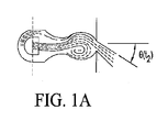
上記の問題を解決しようと出願人が当初至ったのが、図1A〜1Qに示され、参照により本明細書に援用される、本願に共通して所有される米国特許第4,761,036号の「3噴流アイランド」流体回路の方法および構造である。この流体回路のインサート18の幾何形状(図1Gに示す)は、それまでの流体オシレータよりも効果的だったが、出願人らの実験では、ある種の流体およびある温度では、流体インサート18は、他の先行技術の流体オシレータと同様に、状況によっては(a)流体力学的機構を誘発する振動が確実には開始されない可能性、または(b)相互作用チャンバ内で流体噴流の振動誘導機構が確実には維持されない可能性があることが判明した。この2点は所望どおりに振動するスプレーを確実に確立し維持するのに必要とされ、特に低温または粘性の流体では必要とされる。 Applicant's initial intent to solve the above problems was shown in FIGS. 1A-1Q, commonly owned U.S. Pat. No. 4,761,036, incorporated herein by reference. The method and structure of the “3 jet island” fluid circuit of No. Although the geometry of this fluid circuit insert 18 (shown in FIG. 1G) was more effective than previous fluid oscillators, in our experiments, at certain fluids and temperatures, the fluid insert 18 Like other prior art fluid oscillators, depending on the situation, (a) the vibrations that induce the hydrodynamic mechanism may not be reliably initiated, or (b) the vibration-inducing mechanism of the fluid jet in the interaction chamber It has been found that may not be reliably maintained. These two points are required to reliably establish and maintain a spray that vibrates as desired, particularly for cold or viscous fluids.
したがって、より低温の高粘性の流体のスプレーを生成するための改良された方法および装置が必要とされている。 Accordingly, there is a need for an improved method and apparatus for producing a cooler, more viscous fluid spray.
したがって、本発明の目的は、耐久性と信頼性のあるコスト効率のよいノズル構造、流体オシレータ構造、および流体分布またはスプレー生成の方法を提供することで上述の問題を克服し、振動するスプレーの確実な開始および維持を強化し、自動車その他の用途で使用されるノズル組立体の力学的および低温性能の範囲を広げることである。 Accordingly, it is an object of the present invention to overcome the aforementioned problems by providing a durable and reliable cost-effective nozzle structure, fluid oscillator structure, and method of fluid distribution or spray generation. Enhancing reliable start-up and maintenance and extending the range of mechanical and low-temperature performance of nozzle assemblies used in automobiles and other applications.
本発明の別の目的は、流体流が相互作用チャンバ内で流体力学的機構を誘発し始めると、特に低温または粘性の流体で、所望の振動するスプレーを直ちに確立し維持できる、信頼性の高い流体ノズルおよびオシレータ回路を提供することである。 Another object of the present invention is a reliable, capable of immediately establishing and maintaining the desired oscillating spray once the fluid flow begins to induce a hydrodynamic mechanism in the interaction chamber, especially with cold or viscous fluids. A fluid nozzle and oscillator circuit is provided.
本発明の一例示的実施形態によると、流体回路は、流体オシレータを有するノズル組立体として構成されている。流体オシレータまたは流体回路は、流体回路内に画定される流路を受けて境界を提供するチャネル、ポートまたはスロットを画定するハウジング内で使用されるように構成されていることが多い。流体オシレータまたは流体回路がいかに使用され得るかの例としては、出願人の米国特許第7651036号の図4(本明細書にも図1Fとして含まれる)に示されるように、後述する新規の流体インサートを有するノズル組立体がハウジングといっしょに構成され、該ハウジングは、内部ルーメンと1つ以上のポートまたはスロットとで実質的に中空の流体不透過構造を画定し、該ポートまたはスロットは、滑らかなスロット壁内部表面で略長方形の通路または孔を画定している。 According to an exemplary embodiment of the present invention, the fluid circuit is configured as a nozzle assembly having a fluid oscillator. Fluid oscillators or fluid circuits are often configured for use in a housing that defines a channel, port or slot that receives and provides a flow path defined in the fluid circuit. An example of how a fluid oscillator or fluid circuit may be used is the novel fluid described below, as shown in FIG. 4 of Applicant's US Pat. No. 7651036 (also included herein as FIG. 1F). A nozzle assembly having an insert is configured with the housing, the housing defining a substantially hollow fluid impervious structure with an internal lumen and one or more ports or slots, the ports or slots being smooth A substantially rectangular passage or hole is defined on the interior surface of the slot wall.
ノズル組立体は、ハウジングの側壁内に画定されているスロット内にきつく受けられて保持されるような寸法の1つ以上の流体回路インサートまたはチップを含むように構成され得る。流体回路インサートがハウジングのポートまたはスロット内にきつく嵌ると、ノズル組立体はハウジングの内部ルーメンとハウジング外部間を流体連通するチャネルを提供するので、ハウジングの内部ルーメンに流入する流体を用いて、ハウジングの向きおよび構成によって遠位方向に向けて振動するスプレーを生成することができる。 The nozzle assembly may be configured to include one or more fluid circuit inserts or tips dimensioned to be tightly received and retained in a slot defined in the sidewall of the housing. When the fluid circuit insert fits tightly within a port or slot in the housing, the nozzle assembly provides a channel in fluid communication between the housing inner lumen and the housing exterior so that fluid flowing into the housing inner lumen can be used to Depending on the orientation and configuration, a spray that vibrates in the distal direction can be generated.
本発明の新規の流体回路の幾何形状は、反復可能な振動噴流ストリームおよびそれに続いてスプレーを生成する移動渦を確実に形成できる、新規の驚くべき堅牢な振動誘発および維持機構で動作する。本発明の回路の現試作品では、20°〜120°の扇角度で扁平スプレーが生成された。本発明の流体回路の第1の実施形態は、複数のセクションを有し、これらは互いに共働してそこを通過する流体流に作用して、内部渦および所望の振動するスプレーを生成する。順序としては、加圧された流体はまず入口から流入し、オプションのろ過セクションを通過してから、流体流を分割する3分割パワーノズルセクションに入り第1、第2および第3のパワーノズルを通過する。この第1、第2および第3のパワーノズルは、第1、第2および第3の流体噴流を生成し、渦を生成する相互作用チャンバまたは空洞セクション内へと向けるように構成されている。このチャンバまたは空洞セクションで、3つの噴流は互いに、および内部要素と衝突して、遠位方向に移動する流体渦を開始し維持する。相互作用チャンバまたは空洞セクションは、振動するスプレーを周囲環境へと遠位に噴出するように構成されているスロートまたは出口オリフィスで、遠位側で終了する。 The novel fluid circuit geometry of the present invention operates with a novel and surprisingly robust vibration induction and maintenance mechanism that can reliably form a repeatable oscillating jet stream followed by a moving vortex that produces a spray. In the current prototype of the circuit of the present invention, a flat spray was produced with a fan angle of 20 ° to 120 °. The first embodiment of the fluid circuit of the present invention has a plurality of sections that cooperate with each other to act on the fluid flow therethrough to produce internal vortices and the desired oscillating spray. In order, the pressurized fluid first enters from the inlet, passes through an optional filtration section, and then enters a three-part power nozzle section that divides the fluid flow through the first, second and third power nozzles. pass. The first, second, and third power nozzles are configured to generate first, second, and third fluid jets and direct them into an interaction chamber or cavity section that generates vortices. In this chamber or cavity section, the three jets collide with each other and internal elements to initiate and maintain a fluid vortex moving in the distal direction. The interaction chamber or cavity section terminates distally with a throat or outlet orifice that is configured to eject an oscillating spray distally to the surrounding environment.
本発明によると、改良されたノズル組立体は、少なくとも1つの流体オシレータを含み、該流体オシレータはその内部を流れる加圧された流体に作用して、振動する流体滴スプレーを生成して方向付ける。流体オシレータの内部幾何形状により、流体噴流は、第1、第2および第3のパワーノズルから相互作用チャンバ内へ、そして第1、第2および第3のアイランド壁区分を画定し上向きに突出するアイランド突起へと向けられる。アイランド突起は、相互作用チャンバの遠位端またはスプレー端の出口オリフィスから離間しているが共通の中心軸線に沿って揃っており、相互作用チャンバは、パワーノズル幅Pwの12.5〜13.5倍の範囲の(好ましくは13Pwの)相互作用領域幅Iwを有する相互作用領域を画定している。相互作用領域は、7.5〜8.5Pwの範囲の軸方向長さまたは高さIlを有し、第1と第3の(最外側の)噴流は、下流で、中央のまたは第2のオリフィスから2.5〜3Pwに等しい距離だけ遠位に離間している選択された噴流交差点Jlで交差する。第1と第2の(最外側の)噴流は、好ましくは約110度である選択された噴流交差角JAで交差する第1と第2の噴流軸線に向けられ、かつそれらに沿って揃っている。 In accordance with the present invention, an improved nozzle assembly includes at least one fluid oscillator that acts on the pressurized fluid flowing therein to produce and direct an oscillating fluid droplet spray. . Due to the internal geometry of the fluid oscillator, the fluid jet protrudes upwardly from the first, second and third power nozzles into the interaction chamber and defining first, second and third island wall sections. Directed to the island protrusion. The island protrusions are spaced from the exit orifice at the distal or spray end of the interaction chamber, but are aligned along a common central axis, and the interaction chamber has a power nozzle width Pw of 12.5-13. It defines an interaction region having an interaction region width Iw in the range of 5 times (preferably 13 Pw). Interaction region has an axial length or height I l ranging 7.5~8.5Pw, the first and third (outermost) jets downstream, middle or second only intersect at a selected jet intersection J l is spaced distally equal distance from the orifice to 2.5~3Pw. First and second (outermost) jets aligned preferably first and directed to the second jet axis intersecting at about 110 degrees at a selected jet angle of intersection J A, and along their ing.
本発明の流体素子の幾何形状では、第1、第2および第3のオリフィスは、(a)相互作用チャンバの対向する左右の側壁の間、および(b)第1と第2の湾曲した、短手方向の流体不透過壁区分の間に画定され、第1の湾曲した短手方向壁区分は、選択された半径の第1の円筒形壁セクションを画定する第1のくぼんだ壁表面を提供し、第2の湾曲した短手方向壁区分は、前述の第1のくぼんだ壁表面の選択された半径とほぼ等しい第2の選択された半径の第2の円筒形壁セクションを画定する第2のくぼんだ壁表面を提供している。第1および第2のくぼんだ壁表面は、相互作用チャンバ内で形成され、成長し、動き回る横方向にオフセットした流体渦を受けて収容するように構成されている横方向にオフセットした各円筒形壁セクションを画定している。 In the fluidic device geometry of the present invention, the first, second and third orifices are (a) between opposite left and right sidewalls of the interaction chamber, and (b) first and second curved, A first curved transverse wall section defined between the transverse fluid impermeable wall sections, the first recessed wall surface defining a first cylindrical wall section of a selected radius. And a second curved transverse wall section defines a second cylindrical wall section of a second selected radius approximately equal to the selected radius of the first recessed wall surface described above. A second recessed wall surface is provided. First and second recessed wall surfaces are formed in the interaction chamber and each laterally offset cylindrical shape configured to receive and accommodate a laterally offset fluid vortex that grows and moves around A wall section is defined.
第1、第2および第3の噴流は、相互作用チャンバ内で、双安定性周期的振動サイクルで渦を形成させ動き回らせる。双安定性振動サイクルは、相互作用チャンバの上向きまたは内向きに突出するアイランドの両側を中央噴流が交互に流れて、横方向(たとえば左右)に離間する渦を交互に発生または生成すると開始される。最初、中央噴流は、アイランドの片側(たとえば左側)にあって、同側(たとえば左側)に大きな渦をもたらす。この左側の渦は、左側のオリフィスから流れる左側の噴流を部分的に阻害または抑制して、(a)アイランドの上流、かつ右側のオリフィスの近傍で右側の渦が開始され、(b)右側の噴流が、出口オリフィスまたはスロートルーメンから流出する出力噴流を支配することになり、それによって流体素子のスプレー扇の左端の端部または端が画定されることになる。やがて左側の渦と右側の渦はどちらも遠位に移動し、中央噴流はアイランドの反対側(たとえば右側)へと移動し始める。 The first, second, and third jets move and move around in the interaction chamber with a bistable periodic oscillation cycle. A bistable oscillation cycle is initiated when the central jet flows alternately on both sides of the upwardly or inwardly projecting island of the interaction chamber, generating or generating alternating vortices spaced laterally (eg, left and right). . Initially, the central jet is on one side (eg, the left side) of the island, resulting in a large vortex on the same side (eg, the left side). This left vortex partially obstructs or suppresses the left jet flowing from the left orifice, (a) the right vortex is started upstream of the island and near the right orifice, (b) the right vortex The jet will dominate the output jet exiting the exit orifice or slow lumen, thereby defining the left end or end of the fluid element spray fan. Over time, both the left and right vortices move distally, and the central jet begins to move to the opposite side of the island (eg, the right side).
この移行期の間、出力噴流は、スロートルーメンから放出されるスプレー扇の中心を通過している。中央噴流がアイランドの右側へと横方向に移動するとき、出力噴流スプレーはその扇右端を目がけている。この振動サイクルは、比較的高いサイクル数で繰り返される(サイズおよび動作圧力/流量にもよるが、たとえば300Hzにもなる)。 During this transition period, the output jet passes through the center of the spray fan that is discharged from the slow trum. When the central jet moves laterally to the right side of the island, the output jet spray is aimed at the right edge of the fan. This oscillating cycle is repeated with a relatively high number of cycles (depending on size and operating pressure / flow, for example 300 Hz).
特に低温または粘性の流体で、振動が(a)確実に開始され、(b)流体噴流の振動誘導機構が相互作用チャンバ内で確実に維持されるように、T字形アイランドを有する別の実施形態を改良した。このT字形アイランドを有する流体回路の実施形態は、非常に広範な流体温度および粘性条件で特に堅牢な振動開始を提供する、近位方向に突出する壁セグメントを有する。 Another embodiment with a T-shaped island to ensure that vibrations are (a) reliably initiated, and (b) the fluid jet vibration-inducing mechanism is maintained within the interaction chamber, especially with cold or viscous fluids. Improved. This fluid circuit embodiment having a T-shaped island has a proximally projecting wall segment that provides a particularly robust vibration initiation over a very wide range of fluid temperature and viscosity conditions.
背景技術の図1A〜1Qは、出願人の先の米国特許第7651036号の3噴流アイランド流体回路で説明されているノズル組立体構成要素および流体回路構成を示しており、用語を統一するために本明細書の一部として含まれる。次に図2〜6Bを参照すると、本発明の構造および方法では、振動を誘発する流体力学的(つまり渦の形成と動き)機構の開始および信頼性の強化(つまり、相互作用チャンバ内での流体噴流の誘導機構が広範な環境条件、特に低温または粘性の流体を噴霧する条件でも維持される)によってこの先行技術に改良を加えている。図2〜6Bに示されている、この後説明される改良された流体回路の幾何形状および方法は、出願人の(図1Fに示すハウジング10などの)ハウジング構造内で用いられて、自動車その他の用途で使用される大幅に改良されたノズル組立体を提供するようにされている。本発明の流体噴霧性能を説明する用語としては、図1A〜1Eに示され、また出願人の本願に共通して所有される米国特許第7651036号(その内容を参照により本明細書に援用する)にも説明される、「spray fan(スプレー扇)」および「fan angle(扇角度)」が挙げられる。本明細書に記載する本発明の例示的実施形態によると、流体回路(たとえば100、200または300)は、(図1Fに示すハウジング10などの)ノズル組立体内に構成されている。流体オシレータまたは流体回路は、空洞、ポートまたはスロット20を画定するハウジング内で使用されるように構成されていることが多く、以下に説明する新規の流体インサート(たとえば100、200または300)は、ハウジングを有するノズル組立体内に構成されており、該ハウジングは、内部ルーメンと1つ以上の空洞(たとえば20)ポートまたはスロットとで実質的に中空の流体不透過構造を画定し、該空洞、ポートまたはスロットは、滑らかなスロット壁内部表面で略長方形の通路または孔を画定している。
Background Art FIGS. 1A-1Q illustrate the nozzle assembly components and fluid circuit configurations described in Applicant's earlier US Pat. No. 7,615,036, three jet island fluid circuit, to unify terminology. Included as part of this specification. Referring now to FIGS. 2-6B, in the structure and method of the present invention, the initiation of the hydrodynamic (ie, vortex formation and movement) mechanism that induces vibration and enhanced reliability (ie, within the interaction chamber). The fluid jet induction mechanism is maintained over a wide range of environmental conditions, especially under conditions of spraying cold or viscous fluids). The improved fluid circuit geometries and methods described below, shown in FIGS. 2-6B, are used within Applicants' housing structures (such as the
本発明によると、ノズル組立体は、ハウジングの側壁内に画定されている空洞またはスロット内にきつく受けられて保持されるような寸法の1つ以上の流体回路インサートまたはチップ(たとえば100、200または300)を含むように構成されている。流体回路インサート(たとえば100、200または300)がハウジングの空洞またはスロット(たとえば20)内にきつく嵌ると、ノズル組立体はハウジングの内部ルーメン(加圧された流体の流体入口を提供)とハウジング外部間を流体連通するチャネルを提供するので、ハウジングの内部ルーメンに流入する流体を用いて、ハウジングの向きおよび構成によって遠位方向に向けて振動するスプレーを生成することができる。 In accordance with the present invention, the nozzle assembly is one or more fluid circuit inserts or tips (eg, 100, 200 or sized) such that they are tightly received and retained in a cavity or slot defined in the side wall of the housing. 300). When the fluid circuit insert (eg, 100, 200, or 300) fits tightly within the housing cavity or slot (eg, 20), the nozzle assembly provides a housing internal lumen (providing a fluid inlet for pressurized fluid) and the housing exterior. By providing a channel in fluid communication therewith, fluid flowing into the inner lumen of the housing can be used to produce a spray that vibrates in the distal direction depending on the orientation and configuration of the housing.
(たとえば図1Fに示す10と同様の)ノズル組立体のヘッドは、2部品構成であり得る。ハウジングのノズルヘッドは、2つの主要なノズル部品のうちの1つとして空洞またはソケット(たとえば20)を含む場合がある。もう1つの部品は流体インサートまたはチップ(たとえば100、200または300)である。ノズルヘッドが流体インサートまたはチップを受ける空洞を含む場合、この空洞内に画定されている概ね平坦な床面は、ハウジング遠位方向に突出する囲みの遠位スプレー噴出側表面に画定される、幅のある概ね長方形の開口部で終わる。内部では、入口からの流体搬送ルーメンが、ノズルヘッド内部、および空洞側壁表面の開口部(たとえば封止表面22)で終わる流体入口供給チャネルまたはルーメンと、流体連通している。各流体供給ルーメンは、ノズルヘッドの空洞内に画定された内部容積と流体連通し、加圧された流体がノズル供給チャネル内へと送出されそこを通過すると、この流体は空洞内、そして流体素子(たとえば100、200または300)内に流入し通過する。
The head of the nozzle assembly (eg, similar to 10 shown in FIG. 1F) can be a two-part configuration. The nozzle head of the housing may include a cavity or socket (eg, 20) as one of the two main nozzle components. Another part is a fluid insert or tip (
流体インサートまたはチップ(後で詳述するが、たとえば100、200または300)は概ね平らな部材であり、ハウジングの空洞20内に圧入されまたは押し込まれるようにされていて、ハウジングの空洞の壁が該インサートに及ぼす圧力によって空洞内にしっかり保持される。そのために、ハウジングは、圧力がかかるとわずかに変形する堅いプラスチックで作製される。空洞には上壁と底壁とがあり、インサート(たとえば100、200または300)の上面と底面の間のインサート厚さとほぼ等しい距離だけ離間している。所望により、インサートの中央あたりをいくらか厚くして、底面をいくらか湾曲させてもよい。インサートの側壁も同様に、インサートの左右または横方向の両端の間の幅とほぼ等しい距離だけ離間している。好ましい実施形態では、流体回路インサート(たとえば100、200または300)は、ノズルヘッドの空洞20よりも数千分の1インチだけ幅が広くてもよい。インサート(たとえば100、200または300)と空洞20は、軸方向長さに沿って先細になって、露出している遠位端のほうが広く、挿入方向の近位端に向けて狭くなっていてもよい。これは徐々に先細になってもよいし、(たとえば図2に示すように)どこか1か所以上で互いに対してわずかに角度がつくようにして、先細にしてもよい。
The fluid insert or tip (described in detail below, eg, 100, 200, or 300) is a generally flat member that is press-fitted or pushed into the
流体オシレータは、インサート(たとえば100、200または300)において、流体通路を画定する基板上面の複数の凹んだ部分として画定される。流体素子の全要素が、インサートまたはチップ上面に設けられた深さが等しいかまたは異なる凹所またはトラフとして画定される。流体インサート(たとえば100、200または300)がハウジングのスロットまたは空洞に完全に挿入されると、ハウジングの内部ルーメンは空洞への開口部を画定し、この開口部はインサートの入口と揃って連通するので、ハウジング入口(たとえば16)に流入するウォッシャ液または水は、流体素子の相互作用チャンバ(たとえば118、218または318)に流入してその中で振動する渦を生成し、それによって振動が確立され、流体噴流が前後動させられて所望のスプレー130が生成され、流出オリフィス(たとえば120、220または320)から放出される。選択された流体インサート(たとえば100、200または300)がノズルヘッドの空洞20内に圧入されまたは押し込まれると、空洞の側壁22はわずかに広がって、より高い圧力をインサート中央部分に沿って加える。インサート(たとえば100、200または300)の上面に形成されたオシレータは、インサートの両端間でほぼ真ん中に位置し、空洞の内壁に対し非常に密に封止されているので、インサート表面または空洞表面に形成された流体オシレータは、圧入係合により加えられる圧力のみによって封止され得る。
The fluid oscillator is defined in the insert (eg, 100, 200 or 300) as a plurality of recessed portions on the top surface of the substrate that define the fluid passageway. All elements of the fluidic element are defined as recesses or troughs of equal or different depth provided on the top surface of the insert or chip. When a fluid insert (eg, 100, 200, or 300) is fully inserted into a slot or cavity in the housing, the inner lumen of the housing defines an opening into the cavity that communicates with the inlet of the insert. So, washer fluid or water flowing into the housing inlet (eg 16) flows into the interaction chamber (
なお、ノズルヘッドの空洞と流体インサート(たとえば100、200または300)は略平坦に図示しているが、所望のノズルヘッド形状およびスプレーパターン(たとえば130)によっては、円弧状でも、曲がっていても、その他の構成でもよい。同様に、オシレータのチャネルは、インサートの上面と底面の両方に、または空洞の上壁と底壁の両方に画定してもよい。唯一の制限は、どの表面に画定される場合も、流体オシレータは、ハウジングの空洞内に圧入されることで加えられる圧力により、当接する表面によって封止されるということである。 It should be noted that the nozzle head cavity and fluid insert (eg, 100, 200, or 300) are shown to be substantially flat, but depending on the desired nozzle head shape and spray pattern (eg, 130), it may be arcuate or curved. Other configurations may be used. Similarly, the oscillator channels may be defined on both the top and bottom surfaces of the insert, or on both the top and bottom walls of the cavity. The only limitation is that, if defined on any surface, the fluid oscillator is sealed by the abutting surface by the pressure applied by being pressed into the cavity of the housing.
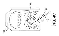
図2〜4Cに示す本発明の第1の実施形態によると、スプレーを生成するための改良された方法および装置には、好ましくは空洞を有するノズル組立体(たとえば図1Fに示すような、空洞20を有するスプレーハウジング10)が含まれるが、改良された3噴流アイランド流体回路100を受けるように構成されている。図2は、第1のパワーノズル114A、第2のパワーノズル114Bおよび第3のパワーノズル114Cからの第1、第2および第3の噴流J1、J2、J3を受けてこれに作用するように構成されている相互作用領域118を有する、改良された3噴流アイランド流体オシレータ100を示す上面図または平面図である。図4A、4Bおよび4Cから最もよくわかるように、振動サイクル中、中央噴流J2は中心軸線102に沿って遠位に流れ、相互作用チャンバ118内へと内向きに突出する新規のアイランド形障害物126に直接衝突し、図3Aに示すように、高粘性流体で、精密かつより均一な振動するスプレーを生成するのに使用される。
In accordance with the first embodiment of the present invention shown in FIGS. 2-4C, an improved method and apparatus for generating a spray preferably includes a nozzle assembly having a cavity (eg, a cavity as shown in FIG. 1F). A spray housing 10) having 20 is included, but is configured to receive an improved three-jet
図2に示す本発明の流体回路100の第1の実施形態は、複数のセクションを有し、これらは互いに共働してそこを通過する流体流に作用して、所望の振動するスプレー130を生成する。流体は、近位入口(全体的に112)から流入し、以下に説明する諸セクションを通って下流または遠位に流れ、振動する流体滴スプレーとしてスロートまたは出口120から流出する。用語として、中心軸線または流れ軸線102は、供給入口110の中心からスロート開口部120の中心まで伸長する直線として定義する。オシレータ回路100内を通って遠位に流れる加圧された流体に作用する各要素は、好ましくは中心軸線102に関して対称的に画定されている。
The first embodiment of the
再度図2を参照すると、改良された3噴流アイランドオシレータ回路100は、入口領域112から相互作用チャンバ118内への流体の遠位方向の流れを促進する第1、第2および第3のルーメンまたはパワーノズル114A、114Bおよび114Cと、この3つのパワーノズル14A、14B、14Cの中央の下流で、相互作用チャンバ118内へと突出する、再構成されたアイランド突起126とを備えている。相互作用チャンバ118には上流部分と下流部分があると考えることができ、上流部分は、一対の境界端およびこれら各端から等間隔の長手方向中心線または中心軸線102を有する。例示的実施形態では、第1と第2のパワーノズル114Aおよび114Bは、中心線から横方向に離間して、相互作用チャンバの上流部分の各端のところにあるのがわかり、第3のパワーノズル114Cは、相互作用チャンバの上流部分のほぼ中心線上にある。
Referring again to FIG. 2, the improved three-jet
図2で最もよくわかるように、相互作用チャンバ118は選択された幅Iwを有し、下流を分けている左右の側壁の間に画定され、振動するスプレーが排出される、中心に位置する出口ルーメンまたはスロート120のところで、遠位または下流で終わっている。スロート120は、名目上は中心線102に関して対称的に画定されており、好ましくは選択された短手方向のスロート幅Twを有する長方形のルーメンを画定する。相互作用チャンバ118内では、アイランド126が、第3のパワーノズル114Cから中心線102上の真下かつ遠位に離間しており、選択された短手方向のアイランド幅lwを有するほぼ平坦な短手方向遠位側アイランド壁区分を有する。各パワーノズルは、選択された流れ軸線角度を有する選択されたパワーノズル流れ軸線に沿って流れを生成し、また、初めは該選択されたパワーノズルの流れ軸線に沿って中心決めされる、各パワーノズルに対応する方向付けられた流体噴流J1、J2、J3を生成する選択されたパワーノズル幅Pwを有する。第1と第2の横方向に離間したパワーノズル114A、114Bは、相互作用領域内で、アイランド126の下流または遠位の噴流交差点JLで選択された噴流交差鈍角JAで交差する、第1と第2の流体噴流J1、J2を生成する。噴流交差角度「JA」は、具体的には「鈍角」と定義されるが、それは直角(つまり90度)よりも大きいが180度よりは小さいからである。開発試作品で実験と評価を行った結果、出願人らは、この流体回路の性能は、選択された噴流交差鈍角JAが100〜140度である場合に最良であることを発見した。例示の実施形態では、JAは110度である。アイランド126は、図2および図4A〜4Cに示すように、外側のつまり第1および第2の横方向に離間したパワーノズル114A、114Bの遠位または下流に構成されているのがわかる。
As best seen in FIG. 2, the
出願人らが発見したところでは、これらの要素を適切に加圧し、方向付け、スケール設定することによって、スロートの右側の側壁そして左側の側壁に交互に近接してスロートからより均一に放出されるようにアイランド126の後ろつまり下流を遠位に流れる、改良された流れ渦を生成することができる。アイランド126の好ましい実施形態として、改良された三角形および位置が選択されている。略三角形のアイランド126は、図4A〜4Cで最もよくわかるように、角のうちの1つが中央パワーノズル114Cから流れてくる流体噴流J3と対向するように、向けられている。
Applicants have discovered that by properly pressurizing, directing, and scaling these elements, they are released more uniformly from the throat in close proximity to the right and left side walls of the throat. Thus, an improved flow vortex can be generated that flows distally behind or downstream of the
流体オシレータ回路100では、第1、第2および第3のオリフィス114A、114Bおよび114Cは、相互作用チャンバの対向する左右の側壁の間、および第1と第2の湾曲した、短手方向の流体不透過壁区分140、150の間に画定されており、第1の湾曲した短手方向壁区分140は、選択された半径の第1の円筒形壁セクションを画定する第1のくぼんだ壁表面142を提供し、第2の湾曲した短手方向壁区分150は、前述の第1のくぼんだ壁表面の選択された半径とほぼ等しい第2の選択された半径の第2の円筒形壁セクションを画定する第2のくぼんだ壁表面152を提供している。第1および第2のくぼんだ壁表面142、152は、相互作用チャンバ118内で形成され、成長し、動き回る横方向にオフセットした流体渦(たとえば図4Aおよび4Cを参照)を受けて収容するように構成されている横方向にオフセットした各円筒形壁セクションを画定している。
In the
3つの流体噴流J1、J2、J3は、順に図4A、4Bおよび4Cに示すように、相互作用チャンバ118内で、双安定性周期的振動サイクルで渦を形成させ、動き回らせる。双安定性振動サイクルは、相互作用チャンバの上向きに突出するアイランド126の両側を中央噴流J3が交互に流れて、横方向(たとえば左右)に離間する渦を交互に発生させまたは生成すると開始される。最初、図4Aに示すように、中央噴流J3は、アイランドの片側(つまり左側)にあって、ここ左側に大きな渦LVをもたらす。左側の渦LVは、左側のオリフィスl14Aから流れる左側の噴流J1を部分的に阻害または抑制して、(a)アイランド126の上流、かつ右側のオリフィス114Bの近傍で右側の渦が開始され、(b)右側の噴流J2が、出口オリフィスまたはスロートルーメン120から流出する出力噴流を支配することになり、それによって流体素子のスプレー130の扇形を画定する横移動の左端の端部または端が画定されることになる。やがて左側の渦と右側の渦はどちらもチャンバ118内を遠位に移動し、中央噴流J3はアイランド126の反対側(つまり右側)へと横方向に変位または移動を開始させられる。
The three fluid jets J1, J2, J3 are swirled in a bi-stable periodic oscillation cycle in the
この移行期の間(図4Bに示す)、出口オリフィス120からのスプレー出力噴流は、横方向に移動してスプレー扇の中心を通過している。中央噴流がアイランド126の右側へと横方向に移動するとき(図4Cに示す)、出口オリフィス120からの噴流スプレーはその右端に向けられる。この振動サイクルは、比較的高いサイクル数で繰り返される(サイズおよび動作圧力/流量にもよるが、たとえば300Hzにもなる)。
During this transition period (shown in FIG. 4B), the spray output jet from the
第1、第2および第3の噴流J1、J2、J3は、相互作用チャンバ118内で、双安定性周期的振動サイクルで渦を形成させ、横方向および遠位方向に移動させる。この双安定性振動サイクルは、上向きに突出するアイランド126の左右の(または横方向に対向する)側を中央噴流J3が交互に流れ始めて、遠位方向に移動し横方向(たとえば左右)に離間する渦を交互に発生または生成させると開始される。この振動誘発方法の結果として、強化された3噴流アイランド流体回路100は、低温の粘性流体で、所与のノズル組立体のスプレー扇角度内でより均一なスプレーパターンの改良されたスプレーを生成する。噴霧性能を図3Aのグラフの実線で示す。図3Aは、スプレーパターンの扇全体の全スプレーに対するセル体積%を示す(選択されたスプレー扇角度については、たとえば図1Cおよび1Eを参照)。セル当たりのスプレー体積の結果は、全体積の約1.6%から全体積の約2.2%の範囲であり、これは出願人の先行技術のフィードバックオシレータ(点線)またはマッシュルームオシレータ(破線)が生成するスプレーよりもはるかに均一である。
The first, second and
本発明の方法によると、改良された3噴流アイランドのパワーノズル114A、114Bおよび114Cには、自明ではないが別個の驚くべき効果的な構成が少なくとも2つある。
A)ほぼ均一なスプレーパターンでは、パワーノズル114A、114Bおよび114Cは3つとも、ほぼ等しいルーメン面積(たとえば長方形断面の幅と深さ)を有する。これにより、スプレー扇全体で均一なスプレー分布が得られる(図3Aに示すとおり)。
B)あるいは、大量噴霧用のスプレーパターンでは、(たとえばパワーノズルが3つとも等しい深さを有する場合)、(114A、114Bと同様の)両側のパワーノズルのルーメン面積は等しく、(114Cよりも大きい)中央パワーノズルよりもわずかに大きい。これにより、スプレー扇の端部の流体量は少し増える(図3Bの点線で示すとおり)。
In accordance with the method of the present invention, the improved three jet
A) In a substantially uniform spray pattern, all three
B) Or, in the spray pattern for mass spraying (for example, when all three power nozzles have the same depth), the lumen areas of the power nozzles on both sides are the same (similar to 114C) Slightly larger than the central power nozzle. This slightly increases the amount of fluid at the end of the spray fan (as shown by the dotted line in FIG. 3B).
上述したように、図1に示すような噴流交差角度JAは、100〜140度の範囲である。出願人らは90〜180度の範囲で試験して、上述の構成で最高の動作をするには、JAは100〜140度の範囲であるべき(好ましくは110度)ということを見出した。以前(出願人の先の米国特許第7、472、848号および同第7、651、036号)は、噴流の角度は鈍角ではなく180度の「直線」角度だったので、左右のパワーノズルからの噴流は、アイランド24から遠位または下流にあるパワーノズル開口部から直接互いに向かうことになった(たとえば先の米国特許第7、472、848号の図10および11、ならびに先の米国特許第7、651、036号の図5A〜13(本明細書では図1G〜1Qとして複製)を参照)。出願人の開発研究および実験から、本発明の性能を改良するには、渦生成機構は出願人の先の幾何形状とは異なる働きをする必要があり、また、アイランドの上方または上流にもっと大きい「渦生成」エリアが必要であることが明らかになった。この理由から、第1、第2および第3のオリフィス114A、114Bおよび114Cを相互作用チャンバの対向する左右の側壁の間、および逆さにしたボウル形の第1と第2の湾曲した、短手方向の流体不透過壁区分140、150の間に画定している。第1のくぼんだ壁表面142は、第1の円筒形壁セクションを画定し、アイランド126の上流または上方かつ左側に、第1のまたは左側の渦生成エリアを提供する。第2のくぼんだ壁表面152は、第2の円筒形壁セクションを画定し、鏡像、すなわちアイランド126の上流または上方かつ右側にある右側の渦生成エリアを提供する。第1および第2のくぼんだ壁表面142、152は、横方向にオフセットした各円筒形壁セクションを画定し、対称的に構成されている左右の渦生成エリアは、相互作用チャンバl18内で形成され、成長し、動き回る、横方向にオフセットした流体渦(たとえば図4Aおよび4Cを参照)を生成し収容するように構成されている。
As described above, the jet crossing angle J A as shown in FIG. 1, in the range of 100 to 140 degrees. Applicants tested in a range of 90 to 180 degrees, to the best operation in the above described arrangement, J A was found that should be in the range of 100 to 140 degrees (preferably 110 degrees) . Previously (Applicant's earlier U.S. Pat. Nos. 7,472,848 and 7,651,036), the jet angle was not a obtuse angle but a "straight" angle of 180 degrees, so left and right power nozzles From the power nozzle openings that are distal or downstream from the island 24 (eg, FIGS. 10 and 11 of previous US Pat. No. 7,472,848, and previous US patents). FIGS. 5A-13 of 7,651,036 (reproduced herein as FIGS. 1G-1Q). From Applicant's development studies and experiments, to improve the performance of the present invention, the vortex generation mechanism must work differently than Applicants' previous geometry and is larger above or upstream of the island It became clear that the “vortex generation” area was necessary. For this reason, the first, second and third curved, short sides of the bowl-shaped first, second and
図2〜4Cに示す新規の幾何形状により得られる流体噴霧性能の改良点としては、次のものが挙げられる。
1.スプレー速度がより速い/効率がより高い。
2.低温性能の改良。
3.扇角度範囲の改良(20〜120度)。高速液滴スプレーでは90度よりも大きい扇角度。
4.均一な扇分布。あるいは所望により次の5。
5.(このほうが好ましい場合は)大量噴霧の分布。
図2で最もよくわかるように、(開発試験で様々な試作品を用いていくつか実験をして発見した)出願人の好ましい実施形態が例示され、ほぼ一律の縮尺で描かれている。三角形のアイランド126が中心軸線102を横方向中心とし、アイランドの近位側または上向きの先端は、同じく中心軸線102を中心とする中央のまたは第3のパワーノズル114Cの中心部と軸方向に揃ってこれに向けられている。
Improvements in fluid spray performance obtained with the novel geometry shown in FIGS. 2-4C include the following.
1. Faster spray speed / higher efficiency.
2. Improved low temperature performance.
3. Improvement of fan angle range (20-120 degrees). Fan angle greater than 90 degrees for high speed droplet spraying.
4). Uniform fan distribution. Or the following 5 if desired.
5. Mass spray distribution (if this is preferred).
As best seen in FIG. 2, the applicant's preferred embodiment (found by experimenting with various prototypes in development trials) is illustrated and drawn in approximately uniform scale. A
流体オシレータ回路100では、第1、第2および第3のオリフィス114A、114Bおよび114Cは、相互作用チャンバの対向する左右の側壁の間、および第1と第2の湾曲した、短手方向の流体不透過壁区分140、150の間に画定されて図示されており、第1の湾曲した短手方向壁区分140は、選択された半径の第1の円筒形壁セクションを画定する第1のくぼんだ壁表面142を提供し、第2の湾曲した短手方向壁区分150は、前述の第1のくぼんだ壁表面の選択された半径とほぼ等しい第2の選択された半径の第2の円筒形壁セクションを画定する第2のくぼんだ壁表面152を提供している。第1および第2のくぼんだ壁表面142、152は、相互作用チャンバ118内で形成され、成長し、動き回る横方向にオフセットした流体渦(たとえば図4Aおよび4Cを参照)を受けて収容するように構成されている横方向にオフセットした各円筒形壁セクションを画定している。
In the
次に図2に例示する実施形態を具体的に見ていくと、各パワーノズル(114A、114B、114C)は、選択された深さ(「PD」)およびパワーノズル幅(「Pw」)を有する長方形の溝またはトラフを画定している。流体素子100は、ウォッシャ液を噴霧するように構成されているので、典型的なパワーノズル深さ(「PD」)は1.3ミリメートル(「mm」)、パワーノズル幅(「Pw」)は0.55mmである。流体回路100を画定する流体通路および内部構造要素の構成は、直線寸法または間隔において特徴づけられ、出願人らは、流体スプレー用途に応じてそれらの寸法関係をスケールアップまたはダウンすることができ、それを複数のパワーノズル幅(「Pw」)によって表すことができることを発見している。相互作用チャンバ118内の各要素は、中心軸線102に沿って中央パワーノズル114Cと出口オリフィス120の間で選択された位置に構成され、出口オリフィス120は、これらの軸方向距離を測る基準線となる相互作用チャンバの遠位側端壁160の中心に位置している。
(a)アイランド位置ISL:三角形のアイランド126は、中心軸線102上を中心として出口オリフィス120に対向している平坦な短手方向遠位側の端壁を有する。アイランドの遠位側短手方向の平坦な端壁は、振動チャンバの遠位側端壁160および出口オリフィス120の中心軸線102上の中心から、パワーノズル幅の4.5倍(4.5*Pw)に等しい軸方向間隔だけ、近位または上流に離間している。
(b)アイランド幅ISW:遠位側短手方向の平坦な端壁は、アイランド幅として言及される短手方向幅を有しており、この寸法を調節することは、低温性能を強化するのに重要であることが見出された。アイランド幅を大きくすると、低温での開始圧力も増加し、望ましくない。出願人らは、適切な幅の範囲はPwの3.3〜3.6倍であることを見出した。この幅範囲はまた、現代のプラスチック射出成形法での製造に適している。内向きに突出するアイランド突起をプラスチック成形する場合は十分な大きさが必要だからである。
(c)アイランド高さ:アイランド126は、相互作用チャンバ118の空洞または内部容積の床から上向きまたは内向きに、選択された高さだけ突出している。アイランドの高さは、(射出成形プラスチックなどから部品を製造する実際の限界はもちろんあるが)商業的に無理のない製造工程が可能な範囲で、なるべく小さいのが好ましい。
(d)相互作用領域幅Iw:出願人らは、パワーノズル幅Pwの12.5〜13.5倍の範囲(好ましくは13Pw)が最適な値になることを見出した。
(e)相互作用領域高さIl:相互作用チャンバ118の深さまたは相互作用領域高さ、また相互作用チャンバの横方向の境界を画定する側壁または端壁160が上向きに突出する高さでもある。重要な寸法であり、7.5〜8.5Pwの範囲。
(f)噴流交差点Jl:重要な寸法であり、振動チャンバの遠位側端壁160および出口オリフィス120の中心軸線102上の中心から、Pwの2.5〜3倍(2.5〜3*Pw)の範囲内であるとき、性能が強化されることが観察された。
(g)噴流交差角度JA:上述したように、最外側の噴流J1、J2の噴流軸線が100度〜140度の範囲((図2、図4A〜4Cに示すように)たとえば110度)であるとき最適な性能が得られる。
Turning specifically to the embodiment illustrated in FIG. 2, each power nozzle (114A, 114B, 114C) has a selected depth (“P D ”) and power nozzle width (“Pw”). A rectangular groove or trough having a Since
(A) Island position I SL : The
(B) Island width I SW : The flat side wall in the distal lateral direction has a lateral width referred to as the island width, and adjusting this dimension enhances low temperature performance Has been found to be important. Increasing the island width also increases the starting pressure at low temperatures, which is undesirable. Applicants have found that a suitable range of width is 3.3 to 3.6 times Pw. This width range is also suitable for production with modern plastic injection molding methods. This is because a sufficient size is required when plastic molding is performed on the island protrusions that protrude inward.
(C) Island height: The
(D) Interaction region width Iw: Applicants have found that a range of 12.5 to 13.5 times the power nozzle width Pw (preferably 13 Pw) is an optimum value.
(E) Interaction region height I l : also the depth or interaction region height of the
(F) Jet intersection J l : an important dimension, 2.5-3 times Pw (2.5-3) from the center on the central axis 102 of the distal end wall 160 of the vibrating chamber and the
(G) Jet crossing angle J A : As described above, the jet axis of outermost jets J1 and J2 is in the range of 100 to 140 degrees (as shown in FIGS. 2 and 4A to 4C, for example, 110 degrees). The optimum performance can be obtained.
改良された3噴流アイランド流体回路100は、スロート幅1mm、スロート深さ1.3mmで図2、図4A〜4Cに示すように構成される(長方形のスプレーオリフィス120となる)と、華氏22度で、840mL/分の流量で加圧されたとき、約14m/sのスプレー速度を生成して、60度の扇角度のスプレー扇を生成することができる。これが可能なのは、相互作用チャンバ118内の諸要素の幾何形状により、スプレーの所与の扇角度(たとえば20度〜120度の範囲内)について、パワーノズル面積に対するスロート面積の割合が予想よりも小さくなるからである。
The improved three-jet
例示した例では、60度の扇で、スロート面積はパワーノズル面積の60%である。これに対し、先に特許された出願人のマッシュルーム回路の場合、同じ扇角度で、スロート面積はパワーノズル面積の100%である。このように、流体回路100では、スロート120に至るまでの圧力損失がより少ないので、より高いスプレー速度が可能になる。この実証された高いスプレー速度は、先行技術のノズルと比較してより優れた力学的性能(自動車用途で見られるような風速に対する噴霧性能)となる重要な改良である。
In the illustrated example, the fan is 60 degrees and the throat area is 60% of the power nozzle area. On the other hand, in the case of the applicant's patented mushroom circuit, the throat area is 100% of the power nozzle area at the same fan angle. Thus, in the
低温性能の改良
アイランド位置、アイランド幅、110度の噴流角度(JA)および大きくなった渦形成エリア(アイランドの上流の渦は利用できる)により、流体素子100は、高粘性流体で、より低い流体圧力で振動開始(または「スタート」)することができる。メタノールと水の組成が50:50の洗浄液では、全扇角度(たとえば60度)のノズルスプレーパターンが3psi以上で得られる。出願人らは、もっと小さいアイランド幅でも低温性能が改善されることを見出した。これらの要素が組み合わさって、以前の実施形態よりも良好な低温性能をもたらしている。
Improved low temperature performance Due to island location, island width, 110 degree jet angle (J A ) and increased vortex formation area (vortices upstream of the island are available),
流体スプレーの液滴分布
次に図3Aおよび3Bを参照すると、噴霧性能(スプレー扇(扇角度60度)の体積分布)を測定したグラフが示されている。Y軸は全体に占めるセル体積%を表し、X軸はセル数である。流体回路100を用いるノズル組立体の性能は図3Aの実線で示され、より均一な分布を示している。このことは、使用中、ノズル組立体は、先行技術のノズルと比べて、その扇角度全体により均一に噴霧液体を拡散させることを意味する。この性能は、フィードバック流体素子またはマッシュルーム流体素子のタイプの流体ノズルよりも、明らかに均一になっている。
Fluid Spray Droplet Distribution Referring now to FIGS. 3A and 3B, graphs showing the spray performance (volume distribution of spray fan (
図3Bは、上述した大量噴霧用スプレーパターンの実施形態(オプション2で説明したように、パワーノズル114Aおよび114Bのルーメン面積のほうが大きく、それよりも小さいルーメンの中央パワーノズル(たとえば114C)を有する)用に構成されている、別の改良された3噴流アイランド流体オシレータの噴霧性能(凡例の右端に示す鎖線)を測定したグラフを示す。
FIG. 3B shows the embodiment of the spray pattern for mass spray described above (as described in option 2), the
図4A〜4Cに戻ると、流体素子100内で振動するスプレーを生成させ維持する動作機構について、ある振動サイクル中の渦の位置および大きさを示す時系列的な静止画で説明している。本発明の方法によると、3噴流双安定オシレータ100の振動サイクルは、中央噴流(「J3」)がアイランド126の対向する左右の側を交互に遠位方向に流れて図示のように交互に渦を発生させると、生成される。図4Aでは、中央噴流は大きい渦LVと同じく左側にある。この渦LVは、左側の噴流J1を阻害または抑制し、その結果右側の噴流J2がスロートルーメン120から流出する出力噴流を支配することになって、該出力噴流はスプレー130の扇角度の左端へと押し流される。振動サイクルが進行すると、中央噴流はアイランドの右側に向けて移動し始める。この間、出力噴流は、スロートルーメン120から放出されている扇の中心を通過している。図3Cでは、中央噴流はアイランドの右側にあり、出力噴流はその扇右端にある。この振動サイクルは、比較的高いサイクル数で繰り返される(サイズおよび動作圧力/流量にもよるが、たとえば300Hzにもなる)。
Returning to FIGS. 4A-4C, an operating mechanism for generating and maintaining a oscillating spray in the
大まかにいうと、本発明の3噴流双安定オシレータ100内で流体を制御する方法は、振動する流体滴スプレー(たとえば130、330)としての排出流を生成するために、中を通過する加圧された流体に作用する流体オシレータ(たとえば100、200または300(以下に説明)を必要とし、該オシレータは、該加圧された流体の入口(たとえば、フィルター柱122の列を所望により含み得る充填領域112)を含んでおり、該加圧された流体は、次いで第1、第2および第3のパワーノズル114A、114B、114Cに流入し、各パワーノズルは、ベンチュリ形の先細ルーメンを画定するように構成されている床および側壁を有して、該加圧された流体の移動を加速して該各パワーノズルから流れる第1、第2および第3の流体噴流を形成し、ここで各パワーノズルから得られる噴流は、選択された噴流軸線に沿って揃っている。該流体オシレータは、該入口112と該第1、第2および第3のパワーノズルの間で該流体の流れを接続して可能にする流体連通路を画定し、該流体連通路は、該第1、第2および第3のパワーノズルと流体連通しかつ該第1、第2および第3のパワーノズルからの第1、第2および第3の噴流を受ける相互作用チャンバ118を画定する一対の側壁を含む、境界表面を有する。相互作用チャンバ118は、床と、振動するスプレーが排出される出口オリフィス120と、上向きまたは内向きに突出するアイランド突起126であって、チャンバ118の該床から上向きに突出する第1、第2および第3のアイランド壁区分を画定し、該噴流軸線の交差点に配置され、それによって(図4A、4Bおよび4Cに示すように)該第1、第2および第3のパワーノズルからの該第1、第2および第3の噴流に衝突される、アイランド突起126とを有する。アイランド126は、相互作用チャンバ118内で出口オリフィス120から離間しているが好ましくは共通の長手方向対称軸線に沿って揃っている。
Broadly speaking, the method of controlling fluid within the three-jet
T字形アイランド3噴流の流体素子
図5Aおよび5Bでは2つの追加の実施形態が説明されている。まず図5Aの実施形態では、T字形アイランド3噴流オシレータ回路200が、入口領域212から相互作用チャンバ218へと流体を加速する第1、第2および第3のパワーノズル214A、214B、214Cと、3つのパワーノズル214Cの中心の下流で相互作用チャンバ218内へと突出するT字形アイランド突起226とを備えている。相互作用チャンバ218には上流部分と下流部分があると考えることができ、上流部分は、一対の境界端およびこれら各端から等間隔の長手方向中心線または中心軸線を有する。例示的実施形態では、第1および第2のパワーノズル214Aおよび214Bは、中心線から横方向に離間して、相互作用チャンバの上流部分の各端のところにあるのがわかり、第3のパワーノズル214Cは、相互作用チャンバの上流部分の対称的な中心線または中心軸線のほぼ上にある。
T-
相互作用チャンバ218は選択された幅Iwを有し、下流を分けている左右の側壁の間に画定され、振動するスプレーが排出される、中心に位置する出口ルーメンまたはスロートオリフィス220のところで、遠位または下流で終わっている。スロートオリフィス220は、名目上は中心線に関して対称的に画定されており、選択された短手方向のスロート幅Twを有する長方形のルーメンを画定する。T字形アイランド226は、相互作用チャンバ218の中心線上に位置する中央パワーノズル214Cから下流の真下に位置し、選択された短手方向のアイランド幅lwを有する。各パワーノズルは、選択された流れ軸線角度を有する選択されたパワーノズル流れ軸線に沿って流れを生成し、また、初めは該選択されたパワーノズルの流れ軸線に沿って中心決めされる噴流を生成する選択されたパワーノズル幅Pwを有する。第1および第2の横方向に離間したパワーノズル214A、214Bは、相互作用領域内で、アイランド226の下流または遠位の噴流交差点JLで選択された噴流交差角度JAで交差する、第1と第2の流体噴流を生成する。
The
流体オシレータ回路200では、第1、第2および第3のオリフィス214A、214Bおよび214Cは、相互作用チャンバの対向する左右の側壁の間、および第1と第2の湾曲した、短手方向の流体不透過壁区分240、250の間に画定されて図示されており、第1の湾曲した短手方向壁区分240は、選択された半径の第1の円筒形壁セクションを画定する第1のくぼんだ壁表面242を提供し、第2の湾曲した短手方向壁区分250は、前述の第1のくぼんだ壁表面の選択された半径とほぼ等しい第2の選択された半径の第2の円筒形壁セクションを画定する第2のくぼんだ壁表面252を提供している。第1および第2のくぼんだ壁表面242、252は、相互作用チャンバ218内で形成され、成長し、動き回る横方向にオフセットした流体渦を受けて収容するように構成されている横方向にオフセットした各円筒形壁セクションを画定している。
In the
上述の流体回路100では、出願人らが発見したところでは、オシレータ200の各流体回路要素を適切に加圧し、方向付け、スケール設定することで、スロートの右側の側壁そして左側の側壁に交互に近接してスロートからより均一に放出される、改良された流れ渦をアイランド226の前と後ろで生成できる。アイランド226の好ましい実施形態として、T字形アイランドの形状および位置が選択されている。T字形アイランドアイランド226は、図5Aで最もよくわかるように、ポイントのうちの1つが、中心軸線202に沿って揃っている中央パワーノズル214Cから遠位方向に流れてくる流体と対向するように、向けられている。
In the
次に図5B、6Bおよび6Cを参照すると、別のT字形アイランド3噴流オシレータ回路300が、入口領域312から相互作用チャンバ318へと流体を加速する第1、第2および第3のパワーノズル314A、314B、314Cと、3つのパワーノズル314Cの中心の下流で相互作用チャンバ318内へと突出するT字形アイランド突起326とを備えている。相互作用チャンバ318には上流部分と下流部分があると考えることができ、上流部分は、一対の境界端およびこれら各端から等間隔の長手方向中心線または中心軸線を有する。例示的実施形態では、第1および第2のパワーノズル314Aおよび314Bは、中心線から横方向に離間して、相互作用チャンバの上流部分の各端のところにあるのがわかり、第3のパワーノズル314Cは、相互作用チャンバの上流部分の対称的な中心線または中心軸線のほぼ上にある。
5B, 6B and 6C, another T-shaped
相互作用チャンバ318は選択された幅Iwを有し、下流を分けている左右の側壁の間に画定され、振動するスプレーが排出される、中心に位置する出口ルーメンまたはスロートオリフィス320のところで、遠位または下流で終わっている。スロートオリフィス320は、名目上は中心線に関して対称的に画定されており、選択された短手方向のスロート幅Twを有する長方形のルーメンを画定する。T字形アイランド326は、相互作用チャンバ318の中心線上に位置する中央パワーノズル314Cから下流の真下に位置し、選択された短手方向のアイランド幅lwを有する。各パワーノズルは、選択された流れ軸線角度を有する選択されたパワーノズル流れ軸線に沿って流れを生成し、また、初めは該選択されたパワーノズルの流れ軸線に沿って中心決めされる噴流を生成する選択されたパワーノズル幅Pwを有する。第1および第2の横方向に離間したパワーノズル314A、314Bは、相互作用領域内で、アイランド326の下流または遠位の噴流交差点JLで選択された噴流交差角度JAで交差する、第1と第2の流体噴流を生成する。図5Aおよび5Bに示される流体オシレータの幾何形状は、動作は類似しているが、図5Bに示されるアイランド326のほうが大きく、図5Aに示されるアイランド226よりも「プラスチック射出成形に好都合」にされている。
The
流体オシレータ回路300では、第1、第2および第3のオリフィス314A、314Bおよび314Cは、相互作用チャンバの対向する左右の側壁の間、および第1と第2の湾曲した、短手方向の流体不透過壁区分340、350の間に画定されて図示されており、(たとえば図6Bに示すように)第1の湾曲した短手方向壁区分340は、選択された半径の第1の円筒形壁セクションを画定する第1のくぼんだ壁表面342を提供し、第2の湾曲した短手方向壁区分350は、前述の第1のくぼんだ壁表面の選択された半径とほぼ等しい第2の選択された半径の第2の円筒形壁セクションを画定する第2のくぼんだ壁表面352を提供している。第1および第2のくぼんだ壁表面342、352は、相互作用チャンバ318内で形成され、成長し、動き回る横方向にオフセットした流体渦を受けて収容するように構成されている横方向にオフセットした各円筒形壁セクションを画定している。
In the
次に図6Bおよび6Cを参照すると、これらの要素を適切に加圧し、方向付け、スケール設定することで、アイランド326の上流または近位(前)および下流または遠位(後ろ)で改良された流れ渦を生成することができ、これらの移動渦はスロートの右側の側壁そして左側の側壁に交互に近接して、より均一にスロート320から放出される。アイランド326の好ましい実施形態として、T字形アイランドの形状および位置が選択されている。略T字形のアイランド326は、図6Bおよび6Cで最もよくわかるように、左右の側壁端部またはポイントで終わる横方向に突出する短手方向壁区分、ならびに中央パワーノズル314Cから遠位方向に流れてくる流体と対向する壁端部またはポイントで近位側で終わる近位方向に突出する軸方向に揃った壁区分を有する。図5Aおよび5Bの流体回路の目的は、改良して「スタート」と低温性能を促進することである。典型的には、そのゴールは、華氏零度で50:50のエタノール混合液のノズル圧力を17psiよりも低くすることである(液体の粘性>20cP)。例示の設計はそのような性能、またはさらに良好な性能をもたらすことになる。それに加えて、スプレー230および330ならびに出口オリフィス(たとえば220、320)からのスプレー端部ははるかに鮮明である(つまり、試験ではスプレー端部の液体体積がより多く、扇の外観がより整っていた)。また、スプレーの振動がより効率的なので、所与のTA(スロート面積)/PA(パワーノズル面積)の割合は、スプレー230および330のスプレー扇角度のほうが高い。
Referring now to FIGS. 6B and 6C, these elements have been improved upstream or proximal (front) and downstream or distal (back) of the
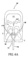
図5Aおよび5Bの流体素子の実施形態200および300の主な特徴は、低温かつ高粘性流体でより良好なスタートアップをもたらした改良されたT字形アイランドの形である(より良好な「低温性能」と特徴づけられる)。この改良は、より良好な振動開始またはスタートを求めて設計したことにより得られた。図6A(図2に例示し上述した改良された3噴流アイランドオシレータ100を示している)ならびに図6Bおよび6C(本発明に提案されるT字形アイランドの形状を示している)を参照すると、オシレータ100の三角形アイランド126(二等辺三角形)は、水で薄めた〜中程度の粘性(たとえば、<15cP)では問題なく動作するが、高粘性の液体(たとえば、>20cP)では苦戦し、振動できないこともある。このことを発見した出願人らがアイランドの形状を逆さにしたT字形構成226、326(ただし、二等辺三角形アイランド126と同じ短手方向幅または底辺寸法Iswを有する)に変えたところ、高粘性液体でより良好な性能を観察した。たとえば図2および6Aに例示するような流体素子100で噴霧する場合、華氏零度でエタノール混合液の流体を噴霧するスプレー扇を生成するのに、25PSIよりも高い流体圧力を要するが、T字形アイランド流体素子200、300は、それよりも大幅に低い流体圧力で動作する(たとえば同じエタノール混合液で17PSI未満)。この振動誘発方法は、図4A〜4Cに例示した上述のものと似ている。たとえば、図6Aが例示しているのは、オシレータ100の三角形アイランド126に対する相互作用チャンバ318内の対称的な(単安定性の振動していない)流れ場であり(上述したとおり)、図6Bが例示しているのは、より新規のT字形アイランドオシレータ300の、この瞬間は対称的な流れ場である。図6Cが例示しているのは、より新規のT字形アイランドオシレータ300の振動している流れ場である。
A key feature of the
高粘性液体ではレイノルズ数が低下するので流れが対称的になる傾向が強く、その結果出力は図6Aや6Bに示すような直線ストリーム(振動しない噴流)となり、オシレータが非振動状態に達すると、ノズル組立体は求められるスプレーパターンを提供できなくなる。 Since the Reynolds number decreases in a highly viscous liquid, the flow tends to be symmetric, and as a result, the output becomes a straight stream (non-vibrating jet) as shown in FIGS. 6A and 6B, and when the oscillator reaches a non-vibrating state, The nozzle assembly will not be able to provide the required spray pattern.
本発明の方法によると、T字形アイランドのパワーノズル314A、314Bおよび314Cには、別個の驚くべき効果的な構成が少なくとも2つある。
A)ほぼ均一なスプレーパターンでは、パワーノズル314A、314Bおよび314Cは3つとも、ほぼ等しいルーメン面積(たとえば長方形断面の幅と深さ)を有する。これにより、スプレー扇全体で均一なスプレー分布が得られる(図3Aに示したものと同様)。
B)あるいは、大量噴霧用のスプレーパターンでは、(たとえばパワーノズルが3つとも等しい深さを有する場合)、(314A、314Bと同様の)両側のパワーノズルのルーメン面積は等しく、中央パワーノズルよりもわずかに大きい(314Cよりも大きい)。これにより、スプレー扇の端部の流体量は少し増える(図3Bの点線で示したものと同様)。
In accordance with the method of the present invention, the T-
A) In a substantially uniform spray pattern, all three
B) Or, in the spray pattern for mass spraying (for example, when all three power nozzles have the same depth), the lumen areas of the power nozzles on both sides (similar to 314A, 314B) are equal and more than the central power nozzle. Is also slightly larger (greater than 314C). This slightly increases the amount of fluid at the end of the spray fan (similar to that shown by the dotted line in FIG. 3B).
先行技術のオシレータでは、および本発明の初期の試作品のいくつかでも(たとえば図2および6Aに示す三角形アイランド126)、中央の流体噴流がアイランド(たとえば図1Jに示す34)の周りでスムーズに2つの流れに分かれると、望ましくない単安定状態により、出口スプレー130が横方向移動しなくなる(つまり振動停止する)ことが見出された。
In prior art oscillators and in some of the early prototypes of the present invention (eg,
本発明のより新規の実施形態は、(たとえばT字形アイランド226、326で、)逆さにしたT字形アイランド326により画定される対向する左右の内角壁区分に、中央噴流(「J3」)からの流れを受けそれに応答して第1および第2の非常に小さい、反対方向に回転するアイランドポケット渦IVCCWおよびIVCW(たとえば図6Bを参照)を生成するように構成されている、第1および第2のL字形アイランド壁区分または内角形ポケットを提供することにより、この問題を解決するものである。第1および第2の反対方向に回転するマイクロ渦は、中央噴流(「J3」)がアイランドの周りで分裂すると立ち上がる。これらの反対方向に回転するマイクロ渦IVCCWおよびIVCWは、圧力(と流れ)が増すにつれて強く大きくなる。その結果、不安定度が増し、中央パワーノズル314Cからの中央噴流J3は、アイランド326の周りで対称的な流れを維持できなくなる。すると中央噴流からの流体流は図6Cに示すようにアイランドの一方の側へと切り替わらざるを得ず、振動する流れ場およびスプレー330を立ち上げる。
A more novel embodiment of the present invention is that from the central jet ("J3") to the opposite left and right inner corner wall sections defined by inverted T islands 326 (eg, with
T字形アイランド流体オシレータ300で振動を開始させるのに必要な加圧された流体流の圧力は、「切替圧力」と呼ばれるが、上述したようにオシレータ300の切替圧力は17PSI未満であり、このことは、切替圧力が25PSIを超えるような先行技術や初期の試作品(たとえば図2および6Aに示す100)に要する切替圧力と比べて大きな進歩である。
The pressure of the pressurized fluid flow required to initiate oscillation in the T-shaped
T字形アイランド流体オシレータ200および300のその他の特徴は、改良された3噴流アイランド流体オシレータ100について上述したことと同様であり、具体的には以下のとおりである。
相互作用領域幅Iw:出願人らは、パワーノズル幅Pwの12.5〜13.5倍の範囲(好ましくは13Pw)が最適な値になることを見出した。
相互作用領域高さIl:重要な寸法であり、7.5〜8.5Pwの範囲。
噴流交差点Jl:重要な寸法であり、2.5〜3Pwの範囲。
噴流交差角度JA:上述したように、最外側の噴流の噴流軸線JAが100度〜140度の範囲であるとき最適な性能が得られ、好ましくは(図6Bおよび6Cに示すように)約110度である。および、
改良されたスプレー速度:回路300では約14m/sのスプレー速度が可能である。これが可能なのは、特殊な幾何形状により、所与の扇角度について、パワーノズル面積に対するスロート面積の割合がより小さくなるからである。
Other features of the T-shaped
Interaction region width Iw: Applicants have found that a range of 12.5 to 13.5 times the power nozzle width Pw (preferably 13 Pw) is an optimum value.
Interaction area height I l : an important dimension, in the range of 7.5 to 8.5 Pw.
Jet intersection J l : an important dimension, in the range of 2.5 to 3 Pw.
Jet crossing angle J A : As described above, optimum performance is obtained when the jet axis J A of the outermost jet is in the range of 100 degrees to 140 degrees, preferably (as shown in FIGS. 6B and 6C). It is about 110 degrees. and,
Improved spray speed: The
このことが、加圧された流体に作用して振動する流体滴スプレーを生成する改良されたノズル組立体および改良された流体オシレータ回路(たとえば100、200、300)を可能にしていることが理解されよう。該オシレータは、流体噴流を第1、第2および第3のパワーノズル(たとえば114A、114B、114C)から相互作用チャンバ(たとえば118)内へ、そして第1、第2および第3のアイランド壁区分を画定している上向きに突出するアイランド突起(たとえば126)へと向ける。各パワーノズルは、選択された長方形のルーメン面積および幅(「Pw」)を有する。アイランドは、7.5〜8.5Pwの範囲の軸方向長さIlを有する相互作用領域を画定する相互作用チャンバの遠位端にある出口オリフィス(たとえば120)から離間しているが共通軸線(たとえば102)に沿って揃っている。最外側噴流(たとえば114A、114B)は、アイランドを越えて、オリフィスから2.5〜3Pwに等しい距離だけ離間している噴流交差点Jlで交差している軸線に沿って、100〜140度の鈍角に向けられる。相互作用チャンバの上流端は、左側および右側の渦生成エリアを画定している第1および第2の横方向にオフセットしたくぼんだ壁のボウル形表面(たとえば142、152)により画定されているので、流体が押し進められるにつれて、流体噴流を誘導する渦が交互に形成され得、次いで遠位に移動させられて流体噴流を相互作用チャンバ内で横方向に誘導し、それによって確実に横方向に振動するスプレー扇が生成されて維持され、該スプレー扇は上述したような改良されたスプレー速度で、20〜120度の範囲の選択された扇角度を有するスプレー(たとえば130、230、330)となって出口オリフィスから噴出される。
It is understood that this enables an improved nozzle assembly and an improved fluid oscillator circuit (eg, 100, 200, 300) that acts on pressurized fluid to produce a vibrating fluid droplet spray. Let's do it. The oscillator directs a fluid jet from first, second and third power nozzles (eg 114A, 114B, 114C) into an interaction chamber (eg 118) and first, second and third island wall sections. Toward an upwardly projecting island projection (eg 126) defining Each power nozzle has a selected rectangular lumen area and width ("Pw"). The island is spaced apart from an exit orifice (eg, 120) at the distal end of the interaction chamber that defines an interaction region having an axial length I l in the range of 7.5 to 8.5 Pw, but is a common axis (For example, 102). Outermost jets (e.g. 114A, 114B) is beyond the island, along an axis intersecting with a jet intersection J l which are separated by equal distance from the orifice to 2.5~3Pw, of 100 to 140 degrees Directed to an obtuse angle. Since the upstream end of the interaction chamber is defined by first and second laterally offset recessed wall bowl-shaped surfaces (
新規の改良されたノズル構成および方法の好ましい実施形態について説明してきたが、当業者であれば、本明細書に記載の教示に鑑み、他の変更形態、変形形態および変化形態に想到しよう。したがって、そのような変更形態、変形形態および変化形態のすべてが、添付の特許請求の範囲に記載される本発明の範囲内にあるものと考えられる。 While preferred embodiments of the new and improved nozzle configuration and method have been described, those skilled in the art will envision other modifications, variations, and variations in light of the teachings herein. Accordingly, all such modifications, variations and variations are considered to be within the scope of the present invention as set forth in the appended claims.
本願は、先の、本願に共通して所有される同時係属の2014年7月15日出願の「IMPROVED THREE JET ISLAND FLUIDIC OSCILLATOR CIRCUIT, METHOD AND NOZZLE ASSEMBLY」と題される米国特許仮出願第62/024762号の優先権を主張するものであり、さらに、先の同時係属の2015年5月1日出願の「TEE−ISLAND IMPROVED THREE JET FLUIDIC OSCILLATOR CIRCUIT, METHOD AND NOZZLE ASSEMBLY」と題される米国特許仮出願第62/155826号の優先権を主張するものである。本願はまた、本願に共通して所有される米国特許第7,267,290号、同第7,472,848号および同第7,651,036号にも関連し、それらの開示全体を参照により本明細書に援用する。 This application is a US Patent Provisional Application No. 62/90 entitled “IMPROVED THREE JET ISLAND FLUIDIC OSCILLATOR CIRCUIT, METHOD AND NOZZLE ASSEMBLY,” filed July 15, 2014, commonly owned by the present application. US Patent Provisional Patent No. 024762, further entitled “TEE-ISLAND IMPROVED THREE JET FLUIDIC OSCILLATOR CIRCUIT, METHODO AND NOZZLE ASSEMBLY” filed on May 1, 2015, earlier filed earlier. The priority of the application No. 62/155826 is claimed. This application is also related to commonly owned U.S. Pat. Nos. 7,267,290, 7,472,848 and 7,651,036, see their entire disclosures. Is incorporated herein by reference.
本発明は、流体操作プロセスおよび装置に関する。より具体的には、本発明は、通常高粘性の流体と関連づけられる低い温度で精密制御されるスプレーを生成するのに用いられる、流体オシレータおよび方法に関する。 The present invention relates to a fluid handling process and apparatus. More specifically, the present invention relates to fluid oscillators and methods used to produce sprays that are precisely controlled at low temperatures typically associated with highly viscous fluids.
流体オシレータは、液体噴流を周期的に屈折させて広範な液体スプレーパターンを提供する能力が、先行技術でもよく知られている。ほとんどの流体オシレータの動作は、機械的可動部品を用いない流体噴流の周期的屈折により特徴づけられる。したがって、流体オシレータには、他の種類のスプレー装置と違って損耗による信頼性と動作性への悪影響がない、という利点がある。 Fluid oscillators are well known in the prior art for the ability to periodically refract liquid jets to provide a wide range of liquid spray patterns. Most fluid oscillator operations are characterized by the periodic refraction of a fluid jet without mechanical moving parts. Thus, the fluid oscillator has the advantage that unlike other types of spray devices, there is no negative impact on reliability and operability due to wear.
流体オシレータの例は、多くの特許文献、たとえば米国特許第3,185,166号(Horton & Bowles)、米国特許第3,563,462号(Bauer)、米国特許第4,052,002号(Stouffer & Bray)、米国特許第4,151,955号(Stouffer)、米国特許第4,157,161号(Bauer)、米国特許第4,231,519号(Stouffer)(RE33,158として再発行)、米国特許第4,508,267号(Stouffer)、米国特許第5,035,361号(Stouffer)、米国特許第5,213,269号(Srinath)、米国特許第5,971,301号(Stouffer)、米国特許第6,186,409号(Srinath)および米国特許第6,253,782号(Raghu)に見ることができる。振動する液体噴流は、この液体噴流が下流で周囲の気体環境中ばらばらになって液滴として分布する際に様々なスプレーパターンを生じさせることができる。 Examples of fluid oscillators include many patent documents such as US Pat. No. 3,185,166 (Horton & Bowles), US Pat. No. 3,563,462 (Bauer), US Pat. No. 4,052,002 ( Stuffer & Bray), US Pat. No. 4,151,955 (Stouffer), US Pat. No. 4,157,161 (Bauer), US Pat. No. 4,231,519 (Stouffer) (RE33,158) ), US Pat. No. 4,508,267 (Stouffer), US Pat. No. 5,035,361 (Stouffer), US Pat. No. 5,213,269 (Srinath), US Pat. No. 5,971,301 (Stouffer), US Pat. No. 6,186,409 (Srinath) and US It can be found in Pat. No. 6,253,782 (Raghu). An oscillating liquid jet can produce various spray patterns as the liquid jet is scattered downstream in the surrounding gaseous environment and distributed as droplets.
一部の高粘性の液体(つまり15〜20センチポアズ)を噴霧するのに、本願に共通して所有される米国特許第6,253,782号に開示される「マッシュルーム・オシレータ」が特に便利であることが見出された。ところが、そのような液体の温度が下がり続け、そのせいで液体の粘性が高くなると(たとえば25センチポアズ)、このタイプのオシレータの性能は、スプレーが広い扇角度で分布するのに十分な振動をする噴流をもたらせなくなるほど低下し得ることも見出されている。この状況は、特に自動車のウォッシャ液用途で問題となる。 The “mushroom oscillator” disclosed in commonly owned US Pat. No. 6,253,782 is particularly useful for spraying some highly viscous liquids (ie, 15-20 centipoise). It was found that there was. However, if the temperature of such a liquid continues to drop, and as a result, the viscosity of the liquid increases (eg, 25 centipoise), the performance of this type of oscillator vibrates sufficiently for the spray to be distributed over a wide fan angle. It has also been found that it can be reduced so that it can no longer produce a jet. This situation is particularly problematic for automotive washer applications.
上記の問題を解決しようと出願人が当初至ったのが、図1A〜1Qに示され、参照により本明細書に援用される、本願に共通して所有される米国特許第4,761,036号の「3噴流アイランド」流体回路の方法および構造である。この流体回路のインサート18の幾何形状(図1Gに示す)は、それまでの流体オシレータよりも効果的だったが、出願人らの実験では、ある種の流体およびある温度では、流体インサート18は、他の先行技術の流体オシレータと同様に、状況によっては(a)流体力学的機構を誘発する振動が確実には開始されない可能性、または(b)相互作用チャンバ内で流体噴流の振動誘導機構が確実には維持されない可能性があることが判明した。この2点は所望どおりに振動するスプレーを確実に確立し維持するのに必要とされ、特に低温または粘性の流体では必要とされる。
Applicant's initial intent to solve the above problems was shown in FIGS. 1A-1Q, commonly owned U.S. Pat. No. 4,761,036, incorporated herein by reference. The method and structure of the “3 jet island” fluid circuit of No. Although the geometry of this fluid circuit insert 18 (shown in FIG. 1G) was more effective than previous fluid oscillators, in our experiments, at certain fluids and temperatures, the
したがって、より低温の高粘性の流体のスプレーを生成するための改良された方法および装置が必要とされている。 Accordingly, there is a need for an improved method and apparatus for producing a cooler, more viscous fluid spray.
したがって、本発明の目的は、耐久性と信頼性のあるコスト効率のよいノズル構造、流体オシレータ構造、および流体分布またはスプレー生成の方法を提供することで上述の問題を克服し、振動するスプレーの確実な開始および維持を強化し、自動車その他の用途で使用されるノズル組立体の力学的および低温性能の範囲を広げることである。 Accordingly, it is an object of the present invention to overcome the aforementioned problems by providing a durable and reliable cost-effective nozzle structure, fluid oscillator structure, and method of fluid distribution or spray generation. Enhancing reliable start-up and maintenance and extending the range of mechanical and low-temperature performance of nozzle assemblies used in automobiles and other applications.
本発明の別の目的は、流体流が相互作用チャンバ内で流体力学的機構を誘発し始めると、特に低温または粘性の流体で、所望の振動するスプレーを直ちに確立し維持できる、信頼性の高い流体ノズルおよびオシレータ回路を提供することである。 Another object of the present invention is a reliable, capable of immediately establishing and maintaining the desired oscillating spray once the fluid flow begins to induce a hydrodynamic mechanism in the interaction chamber, especially with cold or viscous fluids. A fluid nozzle and oscillator circuit is provided.
本発明の一例示的実施形態によると、流体回路は、流体オシレータを有するノズル組立体として構成されている。流体オシレータまたは流体回路は、流体回路内に画定される流路を受けて境界を提供するチャネル、ポートまたはスロットを画定するハウジング内で使用されるように構成されていることが多い。流体オシレータまたは流体回路がいかに使用され得るかの例としては、出願人の米国特許第7651036号の図4(本明細書にも図1Fとして含まれる)に示されるように、後述する新規の流体インサートを有するノズル組立体がハウジングといっしょに構成され、該ハウジングは、内部ルーメンと1つ以上のポートまたはスロットとで実質的に中空の流体不透過構造を画定し、該ポートまたはスロットは、滑らかなスロット壁内部表面で略長方形の通路または孔を画定している。 According to an exemplary embodiment of the present invention, the fluid circuit is configured as a nozzle assembly having a fluid oscillator. Fluid oscillators or fluid circuits are often configured for use in a housing that defines a channel, port or slot that receives and provides a flow path defined in the fluid circuit. An example of how a fluid oscillator or fluid circuit may be used is the novel fluid described below, as shown in FIG. 4 of Applicant's US Pat. No. 7651036 (also included herein as FIG. 1F). A nozzle assembly having an insert is configured with the housing, the housing defining a substantially hollow fluid impervious structure with an internal lumen and one or more ports or slots, the ports or slots being smooth A substantially rectangular passage or hole is defined on the interior surface of the slot wall.
ノズル組立体は、ハウジングの側壁内に画定されているスロット内にきつく受けられて保持されるような寸法の1つ以上の流体回路インサートまたはチップを含むように構成され得る。流体回路インサートがハウジングのポートまたはスロット内にきつく嵌ると、ノズル組立体はハウジングの内部ルーメンとハウジング外部間を流体連通するチャネルを提供するので、ハウジングの内部ルーメンに流入する流体を用いて、ハウジングの向きおよび構成によって遠位方向に向けて振動するスプレーを生成することができる。 The nozzle assembly may be configured to include one or more fluid circuit inserts or tips dimensioned to be tightly received and retained in a slot defined in the sidewall of the housing. When the fluid circuit insert fits tightly within a port or slot in the housing, the nozzle assembly provides a channel in fluid communication between the housing inner lumen and the housing exterior so that fluid flowing into the housing inner lumen can be used to Depending on the orientation and configuration, a spray that vibrates in the distal direction can be generated.
本発明の新規の流体回路の幾何形状は、反復可能な振動噴流ストリームおよびそれに続いてスプレーを生成する移動渦を確実に形成できる、新規の驚くべき堅牢な振動誘発および維持機構で動作する。本発明の回路の現試作品では、20°〜120°の扇角度で扁平スプレーが生成された。本発明の流体回路の第1の実施形態は、複数のセクションを有し、これらは互いに共働してそこを通過する流体流に作用して、内部渦および所望の振動するスプレーを生成する。順序としては、加圧された流体はまず入口から流入し、オプションのろ過セクションを通過してから、流体流を分割する3分割パワーノズルセクションに入り第1、第2および第3のパワーノズルを通過する。この第1、第2および第3のパワーノズルは、第1、第2および第3の流体噴流を生成し、渦を生成する相互作用チャンバまたは空洞セクション内へと向けるように構成されている。このチャンバまたは空洞セクションで、3つの噴流は互いに、および内部要素と衝突して、遠位方向に移動する流体渦を開始し維持する。相互作用チャンバまたは空洞セクションは、振動するスプレーを周囲環境へと遠位に噴出するように構成されているスロートまたは出口オリフィスで、遠位側で終了する。 The novel fluid circuit geometry of the present invention operates with a novel and surprisingly robust vibration induction and maintenance mechanism that can reliably form a repeatable oscillating jet stream followed by a moving vortex that produces a spray. In the current prototype of the circuit of the present invention, a flat spray was produced with a fan angle of 20 ° to 120 °. The first embodiment of the fluid circuit of the present invention has a plurality of sections that cooperate with each other to act on the fluid flow therethrough to produce internal vortices and the desired oscillating spray. In order, the pressurized fluid first enters from the inlet, passes through an optional filtration section, and then enters a three-part power nozzle section that divides the fluid flow through the first, second and third power nozzles. pass. The first, second, and third power nozzles are configured to generate first, second, and third fluid jets and direct them into an interaction chamber or cavity section that generates vortices. In this chamber or cavity section, the three jets collide with each other and internal elements to initiate and maintain a fluid vortex moving in the distal direction. The interaction chamber or cavity section terminates distally with a throat or outlet orifice that is configured to eject an oscillating spray distally to the surrounding environment.
本発明によると、改良されたノズル組立体は、少なくとも1つの流体オシレータを含み、該流体オシレータはその内部を流れる加圧された流体に作用して、振動する流体滴スプレーを生成して方向付ける。流体オシレータの内部幾何形状により、流体噴流は、第1、第2および第3のパワーノズルから相互作用チャンバ内へ、そして第1、第2および第3のアイランド壁区分を画定し上向きに突出するアイランド突起へと向けられる。アイランド突起は、相互作用チャンバの遠位端またはスプレー端の出口オリフィスから離間しているが共通の中心軸線に沿って揃っており、相互作用チャンバは、パワーノズル幅Pwの12.5〜13.5倍の範囲の(好ましくは13Pwの)相互作用領域幅Iwを有する相互作用領域を画定している。相互作用領域は、7.5〜8.5Pwの範囲の軸方向長さまたは高さIlを有し、第1と第3の(最外側の)噴流は、下流で、中央のまたは第2のオリフィスから2.5〜3Pwに等しい距離だけ遠位に離間している選択された噴流交差点Jlで交差する。第1と第3の(最外側の)噴流は、好ましくは約110度である選択された噴流交差角JAで交差する第1と第2の噴流軸線に向けられ、かつそれらに沿って揃っている。 In accordance with the present invention, an improved nozzle assembly includes at least one fluid oscillator that acts on the pressurized fluid flowing therein to produce and direct an oscillating fluid droplet spray. . Due to the internal geometry of the fluid oscillator, the fluid jet protrudes upwardly from the first, second and third power nozzles into the interaction chamber and defining first, second and third island wall sections. Directed to the island protrusion. The island protrusions are spaced from the exit orifice at the distal or spray end of the interaction chamber, but are aligned along a common central axis, and the interaction chamber has a power nozzle width Pw of 12.5-13. It defines an interaction region having an interaction region width Iw in the range of 5 times (preferably 13 Pw). Interaction region has an axial length or height I l ranging 7.5~8.5Pw, the first and third (outermost) jets downstream, middle or second only intersect at a selected jet intersection J l is spaced distally equal distance from the orifice to 2.5~3Pw. The first and third (outermost) jets aligned preferably first and directed to the second jet axis intersecting at about 110 degrees at a selected jet angle of intersection J A, and along their ing.
本発明の流体素子の幾何形状では、第1、第2および第3のオリフィスは、(a)相互作用チャンバの対向する左右の側壁の間、および(b)第1と第2の湾曲した、短手方向の流体不透過壁区分の間に画定され、第1の湾曲した短手方向壁区分は、選択された半径の第1の円筒形壁セクションを画定する第1のくぼんだ壁表面を提供し、第2の湾曲した短手方向壁区分は、前述の第1のくぼんだ壁表面の選択された半径とほぼ等しい第2の選択された半径の第2の円筒形壁セクションを画定する第2のくぼんだ壁表面を提供している。第1および第2のくぼんだ壁表面は、相互作用チャンバ内で形成され、成長し、動き回る横方向にオフセットした流体渦を受けて収容するように構成されている横方向にオフセットした各円筒形壁セクションを画定している。 In the fluidic device geometry of the present invention, the first, second and third orifices are (a) between opposite left and right sidewalls of the interaction chamber, and (b) first and second curved, A first curved transverse wall section defined between the transverse fluid impermeable wall sections, the first recessed wall surface defining a first cylindrical wall section of a selected radius. And a second curved transverse wall section defines a second cylindrical wall section of a second selected radius approximately equal to the selected radius of the first recessed wall surface described above. A second recessed wall surface is provided. First and second recessed wall surfaces are formed in the interaction chamber and each laterally offset cylindrical shape configured to receive and accommodate a laterally offset fluid vortex that grows and moves around A wall section is defined.
第1、第2および第3の噴流は、相互作用チャンバ内で、双安定性周期的振動サイクルで渦を形成させ動き回らせる。双安定性振動サイクルは、相互作用チャンバの上向きまたは内向きに突出するアイランドの両側を中央噴流が交互に流れて、横方向(たとえば左右)に離間する渦を交互に発生または生成すると開始される。最初、中央噴流は、アイランドの片側(たとえば左側)にあって、同側(たとえば左側)に大きな渦をもたらす。この左側の渦は、左側のオリフィスから流れる左側の噴流を部分的に阻害または抑制して、(a)アイランドの上流、かつ右側のオリフィスの近傍で右側の渦が開始され、(b)右側の噴流が、出口オリフィスまたはスロートルーメンから流出する出力噴流を支配することになり、それによって流体素子のスプレー扇の左端の端部または端が画定されることになる。やがて左側の渦と右側の渦はどちらも遠位に移動し、中央噴流はアイランドの反対側(たとえば右側)へと移動し始める。 The first, second, and third jets move and move around in the interaction chamber with a bistable periodic oscillation cycle. A bistable oscillation cycle is initiated when the central jet flows alternately on both sides of the upwardly or inwardly projecting island of the interaction chamber, generating or generating alternating vortices spaced laterally (eg, left and right). . Initially, the central jet is on one side (eg, the left side) of the island, resulting in a large vortex on the same side (eg, the left side). This left vortex partially obstructs or suppresses the left jet flowing from the left orifice, (a) the right vortex is started upstream of the island and near the right orifice, (b) the right vortex The jet will dominate the output jet exiting the exit orifice or slow lumen, thereby defining the left end or end of the fluid element spray fan. Over time, both the left and right vortices move distally, and the central jet begins to move to the opposite side of the island (eg, the right side).
この移行期の間、出力噴流は、スロートルーメンから放出されるスプレー扇の中心を通過している。中央噴流がアイランドの右側へと横方向に移動するとき、出力噴流スプレーはその扇右端を目がけている。この振動サイクルは、比較的高いサイクル数で繰り返される(サイズおよび動作圧力/流量にもよるが、たとえば300Hzにもなる)。 During this transition period, the output jet passes through the center of the spray fan that is discharged from the slow trum. When the central jet moves laterally to the right side of the island, the output jet spray is aimed at the right edge of the fan. This oscillating cycle is repeated with a relatively high number of cycles (depending on size and operating pressure / flow, for example 300 Hz).
特に低温または粘性の流体で、振動が(a)確実に開始され、(b)流体噴流の振動誘導機構が相互作用チャンバ内で確実に維持されるように、T字形アイランドを有する別の実施形態を改良した。このT字形アイランドを有する流体回路の実施形態は、非常に広範な流体温度および粘性条件で特に堅牢な振動開始を提供する、近位方向に突出する壁セグメントを有する。 Another embodiment with a T-shaped island to ensure that vibrations are (a) reliably initiated, and (b) the fluid jet vibration-inducing mechanism is maintained within the interaction chamber, especially with cold or viscous fluids. Improved. This fluid circuit embodiment having a T-shaped island has a proximally projecting wall segment that provides a particularly robust vibration initiation over a very wide range of fluid temperature and viscosity conditions.
背景技術の図1A〜1Qは、出願人の先の米国特許第7651036号の3噴流アイランド流体回路で説明されているノズル組立体構成要素および流体回路構成を示しており、用語を統一するために本明細書の一部として含まれる。次に図2〜6Bを参照すると、本発明の構造および方法では、振動を誘発する流体力学的(つまり渦の形成と動き)機構の開始および信頼性の強化(つまり、相互作用チャンバ内での流体噴流の誘導機構が広範な環境条件、特に低温または粘性の流体を噴霧する条件でも維持される)によってこの先行技術に改良を加えている。図2〜6Bに示されている、この後説明される改良された流体回路の幾何形状および方法は、出願人の(図1Fに示すハウジング10などの)ハウジング構造内で用いられて、自動車その他の用途で使用される大幅に改良されたノズル組立体を提供するようにされている。本発明の流体噴霧性能を説明する用語としては、図1A〜1Eに示され、また出願人の本願に共通して所有される米国特許第7651036号(その内容を参照により本明細書に援用する)にも説明される、「spray fan(スプレー扇)」および「fan angle(扇角度)」が挙げられる。本明細書に記載する本発明の例示的実施形態によると、流体回路(たとえば100、200または300)は、(図1Fに示すハウジング10などの)ノズル組立体内に構成されている。流体オシレータまたは流体回路は、空洞、ポートまたはスロット20を画定するハウジング内で使用されるように構成されていることが多く、以下に説明する新規の流体インサート(たとえば100、200または300)は、ハウジングを有するノズル組立体内に構成されており、該ハウジングは、内部ルーメンと1つ以上の空洞(たとえば20)ポートまたはスロットとで実質的に中空の流体不透過構造を画定し、該空洞、ポートまたはスロットは、滑らかなスロット壁内部表面で略長方形の通路または孔を画定している。
Background Art FIGS. 1A-1Q illustrate the nozzle assembly components and fluid circuit configurations described in Applicant's earlier US Pat. No. 7,615,036, three jet island fluid circuit, to unify terminology. Included as part of this specification. Referring now to FIGS. 2-6B, in the structure and method of the present invention, the initiation of the hydrodynamic (ie, vortex formation and movement) mechanism that induces vibration and enhanced reliability (ie, within the interaction chamber). The fluid jet induction mechanism is maintained over a wide range of environmental conditions, especially under conditions of spraying cold or viscous fluids). The improved fluid circuit geometries and methods described below, shown in FIGS. 2-6B, are used within Applicants' housing structures (such as the
本発明によると、ノズル組立体は、ハウジングの側壁内に画定されている空洞またはスロット内にきつく受けられて保持されるような寸法の1つ以上の流体回路インサートまたはチップ(たとえば100、200または300)を含むように構成されている。流体回路インサート(たとえば100、200または300)がハウジングの空洞またはスロット(たとえば20)内にきつく嵌ると、ノズル組立体はハウジングの内部ルーメン(加圧された流体の流体入口を提供)とハウジング外部間を流体連通するチャネルを提供するので、ハウジングの内部ルーメンに流入する流体を用いて、ハウジングの向きおよび構成によって遠位方向に向けて振動するスプレーを生成することができる。 In accordance with the present invention, the nozzle assembly is one or more fluid circuit inserts or tips (eg, 100, 200 or sized) such that they are tightly received and retained in a cavity or slot defined in the side wall of the housing. 300). When the fluid circuit insert (eg, 100, 200, or 300) fits tightly within the housing cavity or slot (eg, 20), the nozzle assembly provides a housing internal lumen (providing a fluid inlet for pressurized fluid) and the housing exterior. By providing a channel in fluid communication therewith, fluid flowing into the inner lumen of the housing can be used to produce a spray that vibrates in the distal direction depending on the orientation and configuration of the housing.
(たとえば図1Fに示す10と同様の)ノズル組立体のヘッドは、2部品構成であり得る。ハウジングのノズルヘッドは、2つの主要なノズル部品のうちの1つとして空洞またはソケット(たとえば20)を含む場合がある。もう1つの部品は流体インサートまたはチップ(たとえば100、200または300)である。ノズルヘッドが流体インサートまたはチップを受ける空洞を含む場合、この空洞内に画定されている概ね平坦な床面は、ハウジング遠位方向に突出する囲みの遠位スプレー噴出側表面に画定される、幅のある概ね長方形の開口部で終わる。内部では、入口からの流体搬送ルーメンが、ノズルヘッド内部、および空洞側壁表面の開口部(たとえば封止表面22)で終わる流体入口供給チャネルまたはルーメンと、流体連通している。各流体供給ルーメンは、ノズルヘッドの空洞内に画定された内部容積と流体連通し、加圧された流体がノズル供給チャネル内へと送出されそこを通過すると、この流体は空洞内、そして流体素子(たとえば100、200または300)内に流入し通過する。
The head of the nozzle assembly (eg, similar to 10 shown in FIG. 1F) can be a two-part configuration. The nozzle head of the housing may include a cavity or socket (eg, 20) as one of the two main nozzle components. Another part is a fluid insert or tip (
流体インサートまたはチップ(後で詳述するが、たとえば100、200または300)は概ね平らな部材であり、ハウジングの空洞20内に圧入されまたは押し込まれるようにされていて、ハウジングの空洞の壁が該インサートに及ぼす圧力によって空洞内にしっかり保持される。そのために、ハウジングは、圧力がかかるとわずかに変形する堅いプラスチックで作製される。空洞には上壁と底壁とがあり、インサート(たとえば100、200または300)の上面と底面の間のインサート厚さとほぼ等しい距離だけ離間している。所望により、インサートの中央あたりをいくらか厚くして、底面をいくらか湾曲させてもよい。キャビティの側壁も同様に、インサートの左右または横方向の両端の間の幅とほぼ等しい距離だけ離間している。好ましい実施形態では、流体回路インサート(たとえば100、200または300)は、ノズルヘッドの空洞20よりも数千分の1インチだけ幅が広くてもよい。インサート(たとえば100、200または300)と空洞20は、軸方向長さに沿って先細になって、露出している遠位端のほうが広く、挿入方向の近位端に向けて狭くなっていてもよい。これは徐々に先細になってもよいし、(たとえば図2に示すように)どこか1か所以上で互いに対してわずかに角度がつくようにして、先細にしてもよい。
The fluid insert or tip (described in detail below, eg, 100, 200, or 300) is a generally flat member that is press-fitted or pushed into the
流体オシレータは、インサート(たとえば100、200または300)において、流体通路を画定する基板上面の複数の凹んだ部分として画定される。流体素子の全要素が、インサートまたはチップ上面に設けられた深さが等しいかまたは異なる凹所またはトラフとして画定される。流体インサート(たとえば100、200または300)がハウジングのスロットまたは空洞に完全に挿入されると、ハウジングの内部ルーメンは空洞への開口部を画定し、この開口部はインサートの入口と揃って連通するので、ハウジング入口(たとえば16)に流入するウォッシャ液または水は、流体素子の相互作用チャンバ(たとえば118、218または318)に流入してその中で振動する渦を生成し、それによって振動が確立され、流体噴流が前後動させられて所望のスプレー130が生成され、流出オリフィス(たとえば120、220または320)から放出される。選択された流体インサート(たとえば100、200または300)がノズルヘッドの空洞20内に圧入されまたは押し込まれると、空洞の側壁22はわずかに広がって、より高い圧力をインサート中央部分に沿って加える。インサート(たとえば100、200または300)の上面に形成されたオシレータは、インサートの両端間でほぼ真ん中に位置し、空洞の内壁に対し非常に密に封止されているので、インサート表面または空洞表面に形成された流体オシレータは、圧入係合により加えられる圧力のみによって封止され得る。
The fluid oscillator is defined in the insert (eg, 100, 200 or 300) as a plurality of recessed portions on the top surface of the substrate that define the fluid passageway. All elements of the fluidic element are defined as recesses or troughs of equal or different depth provided on the top surface of the insert or chip. When a fluid insert (eg, 100, 200, or 300) is fully inserted into a slot or cavity in the housing, the inner lumen of the housing defines an opening into the cavity that communicates with the inlet of the insert. So, washer fluid or water flowing into the housing inlet (eg 16) flows into the interaction chamber (
なお、ノズルヘッドの空洞と流体インサート(たとえば100、200または300)は略平坦に図示しているが、所望のノズルヘッド形状およびスプレーパターン(たとえば130)によっては、円弧状でも、曲がっていても、その他の構成でもよい。同様に、オシレータのチャネルは、インサートの上面と底面の両方に、または空洞の上壁と底壁の両方に画定してもよい。唯一の制限は、どの表面に画定される場合も、流体オシレータは、ハウジングの空洞内に圧入されることで加えられる圧力により、当接する表面によって封止されるということである。 It should be noted that the nozzle head cavity and fluid insert (eg, 100, 200, or 300) are shown to be substantially flat, but depending on the desired nozzle head shape and spray pattern (eg, 130), it may be arcuate or curved. Other configurations may be used. Similarly, the oscillator channels may be defined on both the top and bottom surfaces of the insert, or on both the top and bottom walls of the cavity. The only limitation is that, if defined on any surface, the fluid oscillator is sealed by the abutting surface by the pressure applied by being pressed into the cavity of the housing.
図2〜4Cに示す本発明の第1の実施形態によると、スプレーを生成するための改良された方法および装置には、好ましくは空洞を有するノズル組立体(たとえば図1Fに示すような、空洞20を有するスプレーハウジング10)が含まれるが、改良された3噴流アイランド流体回路100を受けるように構成されている。図2は、第1のパワーノズル114A、第2のパワーノズル114Bおよび第3のパワーノズル114Cからの第1、第2および第3の噴流J1、J2、J3を受けてこれに作用するように構成されている相互作用領域118を有する、改良された3噴流アイランド流体オシレータ100を示す上面図または平面図である。図4A、4Bおよび4Cから最もよくわかるように、振動サイクル中、中央噴流J2は中心軸線102に沿って遠位に流れ、相互作用チャンバ118内へと内向きに突出する新規のアイランド形障害物126に直接衝突し、図3Aに示すように、高粘性流体で、精密かつより均一な振動するスプレーを生成するのに使用される。
In accordance with the first embodiment of the present invention shown in FIGS. 2-4C, an improved method and apparatus for generating a spray preferably includes a nozzle assembly having a cavity (eg, a cavity as shown in FIG. 1F). A spray housing 10) having 20 is included, but is configured to receive an improved three-jet
図2に示す本発明の流体回路100の第1の実施形態は、複数のセクションを有し、これらは互いに共働してそこを通過する流体流に作用して、所望の振動するスプレー130を生成する。流体は、近位入口(全体的に112)から流入し、以下に説明する諸セクションを通って下流または遠位に流れ、振動する流体滴スプレーとしてスロートまたは出口120から流出する。用語として、中心軸線または流れ軸線102は、供給入口110の中心からスロート開口部120の中心まで伸長する直線として定義する。オシレータ回路100内を通って遠位に流れる加圧された流体に作用する各要素は、好ましくは中心軸線102に関して対称的に画定されている。
The first embodiment of the
再度図2を参照すると、改良された3噴流アイランドオシレータ回路100は、入口領域112から相互作用チャンバ118内への流体の遠位方向の流れを促進する第1、第2および第3のルーメンまたはパワーノズル114A、114Bおよび114Cと、この3つのパワーノズル114A、114B、114Cの中央の下流で、相互作用チャンバ118内へと突出する、再構成されたアイランド突起126とを備えている。相互作用チャンバ118には上流部分と下流部分があると考えることができ、上流部分は、一対の境界端およびこれら各端から等間隔の長手方向中心線または中心軸線102を有する。例示的実施形態では、第1と第2のパワーノズル114Aおよび114Bは、中心線から横方向に離間して、相互作用チャンバの上流部分の各端のところにあるのがわかり、第3のパワーノズル114Cは、相互作用チャンバの上流部分のほぼ中心線上にある。
Referring again to FIG. 2, the improved three-jet
図2で最もよくわかるように、相互作用チャンバ118は選択された幅Iswを有し、下流を分けている左右の側壁の間に画定され、振動するスプレーが排出される、中心に位置する出口ルーメンまたはスロート120のところで、遠位または下流で終わっている。スロート120は、名目上は中心線102に関して対称的に画定されており、好ましくは選択された短手方向のスロート幅Twを有する長方形のルーメンを画定する。相互作用チャンバ118内では、アイランド126が、第3のパワーノズル114Cから中心線102上の真下かつ遠位に離間しており、選択された短手方向のアイランド幅lwを有するほぼ平坦な短手方向遠位側アイランド壁区分を有する。各パワーノズルは、選択された流れ軸線角度を有する選択されたパワーノズル流れ軸線に沿って流れを生成し、また、初めは該選択されたパワーノズルの流れ軸線に沿って中心決めされる、各パワーノズルに対応する方向付けられた流体噴流J1、J2、J3を生成する選択されたパワーノズル幅Pwを有する。第1と第2の横方向に離間したパワーノズル114A、114Bは、相互作用領域内で、アイランド126の下流または遠位の噴流交差点JLで選択された噴流交差鈍角JAで交差する、第1と第2の流体噴流J1、J2を生成する。噴流交差角度「JA」は、具体的には「鈍角」と定義されるが、それは直角(つまり90度)よりも大きいが180度よりは小さいからである。開発試作品で実験と評価を行った結果、出願人らは、この流体回路の性能は、選択された噴流交差鈍角JAが100〜140度である場合に最良であることを発見した。例示の実施形態では、JAは110度である。アイランド126は、図2および図4A〜4Cに示すように、外側のつまり第1および第2の横方向に離間したパワーノズル114A、114Bの遠位または下流に構成されているのがわかる。
As best seen in FIG. 2, the
出願人らが発見したところでは、これらの要素を適切に加圧し、方向付け、スケール設定することによって、スロートの右側の側壁そして左側の側壁に交互に近接してスロートからより均一に放出されるようにアイランド126の後ろつまり下流を遠位に流れる、改良された流れ渦を生成することができる。アイランド126の好ましい実施形態として、改良された三角形および位置が選択されている。略三角形のアイランド126は、図4A〜4Cで最もよくわかるように、角のうちの1つが中央パワーノズル114Cから流れてくる流体噴流J3と対向するように、向けられている。
Applicants have discovered that by properly pressurizing, directing, and scaling these elements, they are released more uniformly from the throat in close proximity to the right and left side walls of the throat. Thus, an improved flow vortex can be generated that flows distally behind or downstream of the
流体オシレータ回路100では、第1、第2および第3のオリフィス114A、114Bおよび114Cは、相互作用チャンバの対向する左右の側壁の間、および第1と第2の湾曲した、短手方向の流体不透過壁区分140、150の間に画定されており、第1の湾曲した短手方向壁区分140は、選択された半径の第1の円筒形壁セクションを画定する第1のくぼんだ壁表面142を提供し、第2の湾曲した短手方向壁区分150は、前述の第1のくぼんだ壁表面の選択された半径とほぼ等しい第2の選択された半径の第2の円筒形壁セクションを画定する第2のくぼんだ壁表面152を提供している。第1および第2のくぼんだ壁表面142、152は、相互作用チャンバ118内で形成され、成長し、動き回る横方向にオフセットした流体渦(たとえば図4Aおよび4Cを参照)を受けて収容するように構成されている横方向にオフセットした各円筒形壁セクションを画定している。
In the
3つの流体噴流J1、J2、J3は、順に図4A、4Bおよび4Cに示すように、相互作用チャンバ118内で、双安定性周期的振動サイクルで渦を形成させ、動き回らせる。双安定性振動サイクルは、相互作用チャンバの上向きに突出するアイランド126の両側を中央噴流J3が交互に流れて、横方向(たとえば左右)に離間する渦を交互に発生させまたは生成すると開始される。最初、図4Aに示すように、中央噴流J3は、アイランドの片側(つまり左側)にあって、ここ左側に大きな渦LVをもたらす。左側の渦LVは、左側のオリフィスl14Aから流れる左側の噴流J1を部分的に阻害または抑制して、(a)アイランド126の上流、かつ右側のオリフィス114Bの近傍で右側の渦が開始され、(b)右側の噴流J2が、出口オリフィスまたはスロートルーメン120から流出する出力噴流を支配することになり、それによって流体素子のスプレー130の扇形を画定する横移動の左端の端部または端が画定されることになる。やがて左側の渦と右側の渦はどちらもチャンバ118内を遠位に移動し、中央噴流J3はアイランド126の反対側(つまり右側)へと横方向に変位または移動を開始させられる。
The three fluid jets J1, J2, J3 are swirled in a bi-stable periodic oscillation cycle in the
この移行期の間(図4Bに示す)、出口オリフィス120からのスプレー出力噴流は、横方向に移動してスプレー扇の中心を通過している。中央噴流がアイランド126の右側へと横方向に移動するとき(図4Cに示す)、出口オリフィス120からの噴流スプレーはその右端に向けられる。この振動サイクルは、比較的高いサイクル数で繰り返される(サイズおよび動作圧力/流量にもよるが、たとえば300Hzにもなる)。
During this transition period (shown in FIG. 4B), the spray output jet from the
第1、第2および第3の噴流J1、J2、J3は、相互作用チャンバ118内で、双安定性周期的振動サイクルで渦を形成させ、横方向および遠位方向に移動させる。この双安定性振動サイクルは、上向きに突出するアイランド126の左右の(または横方向に対向する)側を中央噴流J3が交互に流れ始めて、遠位方向に移動し横方向(たとえば左右)に離間する渦を交互に発生または生成させると開始される。この振動誘発方法の結果として、強化された3噴流アイランド流体回路100は、低温の粘性流体で、所与のノズル組立体のスプレー扇角度内でより均一なスプレーパターンの改良されたスプレーを生成する。噴霧性能を図3Aのグラフの実線で示す。図3Aは、スプレーパターンの扇全体の全スプレーに対するセル体積%を示す(選択されたスプレー扇角度については、たとえば図1Cおよび1Eを参照)。セル当たりのスプレー体積の結果は、全体積の約1.6%から全体積の約2.2%の範囲であり、これは出願人の先行技術のフィードバックオシレータ(点線)またはマッシュルームオシレータ(破線)が生成するスプレーよりもはるかに均一である。
The first, second and
本発明の方法によると、改良された3噴流アイランドのパワーノズル114A、114Bおよび114Cには、自明ではないが別個の驚くべき効果的な構成が少なくとも2つある。
A)ほぼ均一なスプレーパターンでは、パワーノズル114A、114Bおよび114Cは3つとも、ほぼ等しいルーメン面積(たとえば長方形断面の幅と深さ)を有する。これにより、スプレー扇全体で均一なスプレー分布が得られる(図3Aに示すとおり)。
B)あるいは、大量噴霧用のスプレーパターンでは、(たとえばパワーノズルが3つとも等しい深さを有する場合)、(114A、114Bと同様の)両側のパワーノズルのルーメン面積は等しく、(114Cよりも大きい)中央パワーノズルよりもわずかに大きい。これにより、スプレー扇の端部の流体量は少し増える(図3Bの点線で示すとおり)。
In accordance with the method of the present invention, the improved three jet
A) In a substantially uniform spray pattern, all three
B) Or, in the spray pattern for mass spraying (for example, when all three power nozzles have the same depth), the lumen areas of the power nozzles on both sides are the same (similar to 114C) Slightly larger than the central power nozzle. This slightly increases the amount of fluid at the end of the spray fan (as shown by the dotted line in FIG. 3B).
上述したように、図1に示すような噴流交差角度JAは、100〜140度の範囲である。出願人らは90〜180度の範囲で試験して、上述の構成で最高の動作をするには、JAは100〜140度の範囲であるべき(好ましくは110度)ということを見出した。以前(出願人の先の米国特許第7、472、848号および同第7、651、036号)は、噴流の角度は鈍角ではなく180度の「直線」角度だったので、左右のパワーノズルからの噴流は、アイランド24から遠位または下流にあるパワーノズル開口部から直接互いに向かうことになった(たとえば先の米国特許第7、472、848号の図10および11、ならびに先の米国特許第7、651、036号の図5A〜13(本明細書では図1G〜1Qとして複製)を参照)。出願人の開発研究および実験から、本発明の性能を改良するには、渦生成機構は出願人の先の幾何形状とは異なる働きをする必要があり、また、アイランドの上方または上流にもっと大きい「渦生成」エリアが必要であることが明らかになった。この理由から、第1、第2および第3のオリフィス114A、114Bおよび114Cを相互作用チャンバの対向する左右の側壁の間、および逆さにしたボウル形の第1と第2の湾曲した、短手方向の流体不透過壁区分140、150の間に画定している。第1のくぼんだ壁表面142は、第1の円筒形壁セクションを画定し、アイランド126の上流または上方かつ左側に、第1のまたは左側の渦生成エリアを提供する。第2のくぼんだ壁表面152は、第2の円筒形壁セクションを画定し、鏡像、すなわちアイランド126の上流または上方かつ右側にある右側の渦生成エリアを提供する。第1および第2のくぼんだ壁表面142、152は、横方向にオフセットした各円筒形壁セクションを画定し、対称的に構成されている左右の渦生成エリアは、相互作用チャンバl18内で形成され、成長し、動き回る、横方向にオフセットした流体渦(たとえば図4Aおよび4Cを参照)を生成し収容するように構成されている。
As described above, the jet crossing angle J A as shown in FIG. 1, in the range of 100 to 140 degrees. Applicants tested in a range of 90 to 180 degrees, to the best operation in the above described arrangement, J A was found that should be in the range of 100 to 140 degrees (preferably 110 degrees) . Previously (Applicant's earlier U.S. Pat. Nos. 7,472,848 and 7,651,036), the jet angle was not a obtuse angle but a "straight" angle of 180 degrees, so left and right power nozzles From the power nozzle openings that are distal or downstream from the island 24 (eg, FIGS. 10 and 11 of previous US Pat. No. 7,472,848, and previous US patents). FIGS. 5A-13 of 7,651,036 (reproduced herein as FIGS. 1G-1Q). From Applicant's development studies and experiments, to improve the performance of the present invention, the vortex generation mechanism must work differently than Applicants' previous geometry and is larger above or upstream of the island It became clear that the “vortex generation” area was necessary. For this reason, the first, second and third curved, short sides of the bowl-shaped first, second and
図2〜4Cに示す新規の幾何形状により得られる流体噴霧性能の改良点としては、次のものが挙げられる。
1.スプレー速度がより速い/効率がより高い。
2.低温性能の改良。
3.扇角度範囲の改良(20〜120度)。高速液滴スプレーでは90度よりも大きい扇角度。
4.均一な扇分布。あるいは所望により次の5。
5.(このほうが好ましい場合は)大量噴霧の分布。
図2で最もよくわかるように、(開発試験で様々な試作品を用いていくつか実験をして発見した)出願人の好ましい実施形態が例示され、ほぼ一律の縮尺で描かれている。三角形のアイランド126が中心軸線102を横方向中心とし、アイランドの近位側または上向きの先端は、同じく中心軸線102を中心とする中央のまたは第3のパワーノズル114Cの中心部と軸方向に揃ってこれに向けられている。
Improvements in fluid spray performance obtained with the novel geometry shown in FIGS. 2-4C include the following.
1. Faster spray speed / higher efficiency.
2. Improved low temperature performance.
3. Improvement of fan angle range (20-120 degrees). Fan angle greater than 90 degrees for high speed droplet spraying.
4). Uniform fan distribution. Or the following 5 if desired.
5. Mass spray distribution (if this is preferred).
As best seen in FIG. 2, the applicant's preferred embodiment (found by experimenting with various prototypes in development trials) is illustrated and drawn in approximately uniform scale. A
流体オシレータ回路100では、第1、第2および第3のオリフィス114A、114Bおよび114Cは、相互作用チャンバの対向する左右の側壁の間、および第1と第2の湾曲した、短手方向の流体不透過壁区分140、150の間に画定されて図示されており、第1の湾曲した短手方向壁区分140は、選択された半径の第1の円筒形壁セクションを画定する第1のくぼんだ壁表面142を提供し、第2の湾曲した短手方向壁区分150は、前述の第1のくぼんだ壁表面の選択された半径とほぼ等しい第2の選択された半径の第2の円筒形壁セクションを画定する第2のくぼんだ壁表面152を提供している。第1および第2のくぼんだ壁表面142、152は、相互作用チャンバ118内で形成され、成長し、動き回る横方向にオフセットした流体渦(たとえば図4Aおよび4Cを参照)を受けて収容するように構成されている横方向にオフセットした各円筒形壁セクションを画定している。
In the
次に図2に例示する実施形態を具体的に見ていくと、各パワーノズル(114A、114B、114C)は、選択された深さ(「PD」)およびパワーノズル幅(「Pw」)を有する長方形の溝またはトラフを画定している。流体素子100は、ウォッシャ液を噴霧するように構成されているので、典型的なパワーノズル深さ(「PD」)は1.3ミリメートル(「mm」)、パワーノズル幅(「Pw」)は0.55mmである。流体回路100を画定する流体通路および内部構造要素の構成は、直線寸法または間隔において特徴づけられ、出願人らは、流体スプレー用途に応じてそれらの寸法関係をスケールアップまたはダウンすることができ、それを複数のパワーノズル幅(「Pw」)によって表すことができることを発見している。相互作用チャンバ118内の各要素は、中心軸線102に沿って中央パワーノズル114Cと出口オリフィス120の間で選択された位置に構成され、出口オリフィス120は、これらの軸方向距離を測る基準線となる相互作用チャンバの遠位側端壁160の中心に位置している。
(a)アイランド位置ISL:三角形のアイランド126は、中心軸線102上を中心として出口オリフィス120に対向している平坦な短手方向遠位側の端壁を有する。アイランドの遠位側短手方向の平坦な端壁は、振動チャンバの遠位側端壁160および出口オリフィス120の中心軸線102上の中心から、パワーノズル幅の4.5倍(4.5*Pw)に等しい軸方向間隔だけ、近位または上流に離間している。
(b)アイランド幅ISW:遠位側短手方向の平坦な端壁は、アイランド幅として言及される短手方向幅を有しており、この寸法を調節することは、低温性能を強化するのに重要であることが見出された。アイランド幅を大きくすると、低温での開始圧力も増加し、望ましくない。出願人らは、適切な幅の範囲はPwの3.3〜3.6倍であることを見出した。この幅範囲はまた、現代のプラスチック射出成形法での製造に適している。内向きに突出するアイランド突起をプラスチック成形する場合は十分な大きさが必要だからである。
(c)アイランド高さ:アイランド126は、相互作用チャンバ118の空洞または内部容積の床から上向きまたは内向きに、選択された高さだけ突出している。アイランドの高さは、(射出成形プラスチックなどから部品を製造する実際の限界はもちろんあるが)商業的に無理のない製造工程が可能な範囲で、なるべく小さいのが好ましい。
(d)相互作用領域幅Iw:出願人らは、パワーノズル幅Pwの12.5〜13.5倍の範囲(好ましくは13Pw)が最適な値になることを見出した。
(e)相互作用領域高さIl:相互作用チャンバ118の深さまたは相互作用領域高さ、また相互作用チャンバの横方向の境界を画定する側壁または端壁160が上向きに突出する高さでもある。重要な寸法であり、7.5〜8.5Pwの範囲。
(f)噴流交差点Jl:重要な寸法であり、振動チャンバの遠位側端壁160および出口オリフィス120の中心軸線102上の中心から、Pwの2.5〜3倍(2.5〜3*Pw)の範囲内であるとき、性能が強化されることが観察された。
(g)噴流交差角度JA:上述したように、最外側の噴流J1、J2の噴流軸線が100度〜140度の範囲((図2、図4A〜4Cに示すように)たとえば110度)であるとき最適な性能が得られる。
Turning specifically to the embodiment illustrated in FIG. 2, each power nozzle (114A, 114B, 114C) has a selected depth (“P D ”) and power nozzle width (“Pw”). A rectangular groove or trough having a Since
(A) Island position I SL : The
(B) Island width I SW : The flat side wall in the distal lateral direction has a lateral width referred to as the island width, and adjusting this dimension enhances low temperature performance Has been found to be important. Increasing the island width also increases the starting pressure at low temperatures, which is undesirable. Applicants have found that a suitable range of width is 3.3 to 3.6 times Pw. This width range is also suitable for production with modern plastic injection molding methods. This is because a sufficient size is required when plastic molding is performed on the island protrusions that protrude inward.
(C) Island height: The
(D) Interaction region width Iw: Applicants have found that a range of 12.5 to 13.5 times the power nozzle width Pw (preferably 13 Pw) is an optimum value.
(E) Interaction region height I l : also the depth or interaction region height of the
(F) Jet intersection J l : an important dimension, 2.5-3 times Pw (2.5-3) from the center on the central axis 102 of the distal end wall 160 of the vibrating chamber and the
(G) Jet crossing angle J A : As described above, the jet axis of outermost jets J1 and J2 is in the range of 100 to 140 degrees (as shown in FIGS. 2 and 4A to 4C, for example, 110 degrees). The optimum performance can be obtained.
改良された3噴流アイランド流体回路100は、スロート幅1mm、スロート深さ1.3mmで図2、図4A〜4Cに示すように構成される(長方形のスプレーオリフィス120となる)と、華氏22度で、840mL/分の流量で加圧されたとき、約14m/sのスプレー速度を生成して、60度の扇角度のスプレー扇を生成することができる。これが可能なのは、相互作用チャンバ118内の諸要素の幾何形状により、スプレーの所与の扇角度(たとえば20度〜120度の範囲内)について、パワーノズル面積に対するスロート面積の割合が予想よりも小さくなるからである。
The improved three-jet
例示した例では、60度の扇で、スロート面積はパワーノズル面積の60%である。これに対し、先に特許された出願人のマッシュルーム回路の場合、同じ扇角度で、スロート面積はパワーノズル面積の100%である。このように、流体回路100では、スロート120に至るまでの圧力損失がより少ないので、より高いスプレー速度が可能になる。この実証された高いスプレー速度は、先行技術のノズルと比較してより優れた力学的性能(自動車用途で見られるような風速に対する噴霧性能)となる重要な改良である。
In the illustrated example, the fan is 60 degrees and the throat area is 60% of the power nozzle area. On the other hand, in the case of the applicant's patented mushroom circuit, the throat area is 100% of the power nozzle area at the same fan angle. Thus, in the
低温性能の改良
アイランド位置、アイランド幅、110度の噴流角度(JA)および大きくなった渦形成エリア(アイランドの上流の渦は利用できる)により、流体素子100は、高粘性流体で、より低い流体圧力で振動開始(または「スタート」)することができる。メタノールと水の組成が50:50の洗浄液では、全扇角度(たとえば60度)のノズルスプレーパターンが3psi以上で得られる。出願人らは、もっと小さいアイランド幅でも低温性能が改善されることを見出した。これらの要素が組み合わさって、以前の実施形態よりも良好な低温性能をもたらしている。
Improved low temperature performance Due to island location, island width, 110 degree jet angle (J A ) and increased vortex formation area (vortices upstream of the island are available),
流体スプレーの液滴分布
次に図3Aおよび3Bを参照すると、噴霧性能(スプレー扇(扇角度60度)の体積分布)を測定したグラフが示されている。Y軸は全体に占めるセル体積%を表し、X軸はセル数である。流体回路100を用いるノズル組立体の性能は図3Aの実線で示され、より均一な分布を示している。このことは、使用中、ノズル組立体は、先行技術のノズルと比べて、その扇角度全体により均一に噴霧液体を拡散させることを意味する。この性能は、フィードバック流体素子またはマッシュルーム流体素子のタイプの流体ノズルよりも、明らかに均一になっている。
Fluid Spray Droplet Distribution Referring now to FIGS. 3A and 3B, graphs showing the spray performance (volume distribution of spray fan (
図3Bは、上述した大量噴霧用スプレーパターンの実施形態(オプション2で説明したように、パワーノズル114Aおよび114Bのルーメン面積のほうが大きく、それよりも小さいルーメンの中央パワーノズル(たとえば114C)を有する)用に構成されている、別の改良された3噴流アイランド流体オシレータの噴霧性能(凡例の右端に示す鎖線)を測定したグラフを示す。
FIG. 3B shows the embodiment of the spray pattern for mass spray described above (as described in option 2), the
図4A〜4Cに戻ると、流体素子100内で振動するスプレーを生成させ維持する動作機構について、ある振動サイクル中の渦の位置および大きさを示す時系列的な静止画で説明している。本発明の方法によると、3噴流双安定オシレータ100の振動サイクルは、中央噴流(「J3」)がアイランド126の対向する左右の側を交互に遠位方向に流れて図示のように交互に渦を発生させると、生成される。図4Aでは、中央噴流は大きい渦LVと同じく左側にある。この渦LVは、左側の噴流J1を阻害または抑制し、その結果右側の噴流J2がスロートルーメン120から流出する出力噴流を支配することになって、該出力噴流はスプレー130の扇角度の左端へと押し流される。振動サイクルが進行すると、中央噴流はアイランドの右側に向けて移動し始める。この間、出力噴流は、スロートルーメン120から放出されている扇の中心を通過している。図3Cでは、中央噴流はアイランドの右側にあり、出力噴流はその扇右端にある。この振動サイクルは、比較的高いサイクル数で繰り返される(サイズおよび動作圧力/流量にもよるが、たとえば300Hzにもなる)。
Returning to FIGS. 4A-4C, an operating mechanism for generating and maintaining a oscillating spray in the
大まかにいうと、本発明の3噴流双安定オシレータ100内で流体を制御する方法は、振動する流体滴スプレー(たとえば130、330)としての排出流を生成するために、中を通過する加圧された流体に作用する流体オシレータ(たとえば100、200または300(以下に説明)を必要とし、該オシレータは、該加圧された流体の入口(たとえば、フィルター柱122の列を所望により含み得る充填領域112)を含んでおり、該加圧された流体は、次いで第1、第2および第3のパワーノズル114A、114B、114Cに流入し、各パワーノズルは、ベンチュリ形の先細ルーメンを画定するように構成されている床および側壁を有して、該加圧された流体の移動を加速して該各パワーノズルから流れる第1、第2および第3の流体噴流を形成し、ここで各パワーノズルから得られる噴流は、選択された噴流軸線に沿って揃っている。該流体オシレータは、該入口112と該第1、第2および第3のパワーノズルの間で該流体の流れを接続して可能にする流体連通路を画定し、該流体連通路は、該第1、第2および第3のパワーノズルと流体連通しかつ該第1、第2および第3のパワーノズルからの第1、第2および第3の噴流を受ける相互作用チャンバ118を画定する一対の側壁を含む、境界表面を有する。相互作用チャンバ118は、床と、振動するスプレーが排出される出口オリフィス120と、上向きまたは内向きに突出するアイランド突起126であって、チャンバ118の該床から上向きに突出する第1、第2および第3のアイランド壁区分を画定し、該噴流軸線の交差点に配置され、それによって(図4A、4Bおよび4Cに示すように)該第1、第2および第3のパワーノズルからの該第1、第2および第3の噴流に衝突される、アイランド突起126とを有する。アイランド126は、相互作用チャンバ118内で出口オリフィス120から離間しているが好ましくは共通の長手方向対称軸線に沿って揃っている。
Broadly speaking, the method of controlling fluid within the three-jet
T字形アイランド3噴流の流体素子
図5Aおよび5Bでは2つの追加の実施形態が説明されている。まず図5Aの実施形態では、T字形アイランド3噴流オシレータ回路200が、入口領域212から相互作用チャンバ218へと流体を加速する第1、第2および第3のパワーノズル214A、214B、214Cと、第3のパワーノズル214Cの中心の下流で相互作用チャンバ218内へと突出するT字形アイランド突起226とを備えている。相互作用チャンバ218には上流部分と下流部分があると考えることができ、上流部分は、一対の境界端およびこれら各端から等間隔の長手方向中心線または中心軸線を有する。例示的実施形態では、第1および第2のパワーノズル214Aおよび214Bは、中心線から横方向に離間して、相互作用チャンバの上流部分の各端のところにあるのがわかり、第3のパワーノズル214Cは、相互作用チャンバの上流部分の対称的な中心線または中心軸線のほぼ上にある。
T-
相互作用チャンバ218は選択された幅Iwを有し、下流を分けている左右の側壁の間に画定され、振動するスプレーが排出される、中心に位置する出口ルーメンまたはスロートオリフィス220のところで、遠位または下流で終わっている。スロートオリフィス220は、名目上は中心線に関して対称的に画定されており、選択された短手方向のスロート幅Twを有する長方形のルーメンを画定する。T字形アイランド226は、相互作用チャンバ218の中心線上に位置する中央パワーノズル214Cから下流の真下に位置し、選択された短手方向のアイランド幅lwを有する。各パワーノズルは、選択された流れ軸線角度を有する選択されたパワーノズル流れ軸線に沿って流れを生成し、また、初めは該選択されたパワーノズルの流れ軸線に沿って中心決めされる噴流を生成する選択されたパワーノズル幅Pwを有する。第1および第2の横方向に離間したパワーノズル214A、214Bは、相互作用領域内で、アイランド226の下流または遠位の噴流交差点JLで選択された噴流交差角度JAで交差する、第1と第2の流体噴流を生成する。
The
流体オシレータ回路200では、第1、第2および第3のオリフィス214A、214Bおよび214Cは、相互作用チャンバの対向する左右の側壁の間、および第1と第2の湾曲した、短手方向の流体不透過壁区分240、250の間に画定されて図示されており、第1の湾曲した短手方向壁区分240は、選択された半径の第1の円筒形壁セクションを画定する第1のくぼんだ壁表面242を提供し、第2の湾曲した短手方向壁区分250は、前述の第1のくぼんだ壁表面の選択された半径とほぼ等しい第2の選択された半径の第2の円筒形壁セクションを画定する第2のくぼんだ壁表面252を提供している。第1および第2のくぼんだ壁表面242、252は、相互作用チャンバ218内で形成され、成長し、動き回る横方向にオフセットした流体渦を受けて収容するように構成されている横方向にオフセットした各円筒形壁セクションを画定している。
In the
上述の流体回路100では、出願人らが発見したところでは、オシレータ200の各流体回路要素を適切に加圧し、方向付け、スケール設定することで、スロートの右側の側壁そして左側の側壁に交互に近接してスロートからより均一に放出される、改良された流れ渦をアイランド226の前と後ろで生成できる。アイランド226の好ましい実施形態として、T字形アイランドの形状および位置が選択されている。T字形アイランドアイランド226は、図5Aで最もよくわかるように、ポイントのうちの1つが、中心軸線202に沿って揃っている中央パワーノズル214Cから遠位方向に流れてくる流体と対向するように、向けられている。
In the
次に図5B、6Bおよび6Cを参照すると、別のT字形アイランド3噴流オシレータ回路300が、入口領域312から相互作用チャンバ318へと流体を加速する第1、第2および第3のパワーノズル314A、314B、314Cと、3つのパワーノズル314Cの中心の下流で相互作用チャンバ318内へと突出するT字形アイランド突起326とを備えている。相互作用チャンバ318には上流部分と下流部分があると考えることができ、上流部分は、一対の境界端およびこれら各端から等間隔の長手方向中心線または中心軸線を有する。例示的実施形態では、第1および第2のパワーノズル314Aおよび314Bは、中心線から横方向に離間して、相互作用チャンバの上流部分の各端のところにあるのがわかり、第3のパワーノズル314Cは、相互作用チャンバの上流部分の対称的な中心線または中心軸線のほぼ上にある。
5B, 6B and 6C, another T-shaped
相互作用チャンバ318は選択された幅Iwを有し、下流を分けている左右の側壁の間に画定され、振動するスプレーが排出される、中心に位置する出口ルーメンまたはスロートオリフィス320のところで、遠位または下流で終わっている。スロートオリフィス320は、名目上は中心線に関して対称的に画定されており、選択された短手方向のスロート幅Twを有する長方形のルーメンを画定する。T字形アイランド326は、相互作用チャンバ318の中心線上に位置する中央パワーノズル314Cから下流の真下に位置し、選択された短手方向のアイランド幅lwを有する。各パワーノズルは、選択された流れ軸線角度を有する選択されたパワーノズル流れ軸線に沿って流れを生成し、また、初めは該選択されたパワーノズルの流れ軸線に沿って中心決めされる噴流を生成する選択されたパワーノズル幅Pwを有する。第1および第2の横方向に離間したパワーノズル314A、314Bは、相互作用領域内で、アイランド326の下流または遠位の噴流交差点JLで選択された噴流交差角度JAで交差する、第1と第2の流体噴流を生成する。図5Aおよび5Bに示される流体オシレータの幾何形状は、動作は類似しているが、図5Bに示されるアイランド326のほうが大きく、図5Aに示されるアイランド226よりも「プラスチック射出成形に好都合」にされている。
The
流体オシレータ回路300では、第1、第2および第3のオリフィス314A、314Bおよび314Cは、相互作用チャンバの対向する左右の側壁の間、および第1と第2の湾曲した、短手方向の流体不透過壁区分340、350の間に画定されて図示されており、(たとえば図6Bに示すように)第1の湾曲した短手方向壁区分340は、選択された半径の第1の円筒形壁セクションを画定する第1のくぼんだ壁表面342を提供し、第2の湾曲した短手方向壁区分350は、前述の第1のくぼんだ壁表面の選択された半径とほぼ等しい第2の選択された半径の第2の円筒形壁セクションを画定する第2のくぼんだ壁表面352を提供している。第1および第2のくぼんだ壁表面342、352は、相互作用チャンバ318内で形成され、成長し、動き回る横方向にオフセットした流体渦を受けて収容するように構成されている横方向にオフセットした各円筒形壁セクションを画定している。
In the
次に図6Bおよび6Cを参照すると、これらの要素を適切に加圧し、方向付け、スケール設定することで、アイランド326の上流または近位(前)および下流または遠位(後ろ)で改良された流れ渦を生成することができ、これらの移動渦はスロートの右側の側壁そして左側の側壁に交互に近接して、より均一にスロート320から放出される。アイランド326の好ましい実施形態として、T字形アイランドの形状および位置が選択されている。略T字形のアイランド326は、図6Bおよび6Cで最もよくわかるように、左右の側壁端部またはポイントで終わる横方向に突出する短手方向壁区分、ならびに中央パワーノズル314Cから遠位方向に流れてくる流体と対向する壁端部またはポイントで近位側で終わる近位方向に突出する軸方向に揃った壁区分を有する。図5Aおよび5Bの流体回路の目的は、改良して「スタート」と低温性能を促進することである。典型的には、そのゴールは、華氏零度で50:50のエタノール混合液のノズル圧力を17psiよりも低くすることである(液体の粘性>20cP)。例示の設計はそのような性能、またはさらに良好な性能をもたらすことになる。それに加えて、スプレー230および330ならびに出口オリフィス(たとえば220、320)からのスプレー端部ははるかに鮮明である(つまり、試験ではスプレー端部の液体体積がより多く、扇の外観がより整っていた)。また、スプレーの振動がより効率的なので、所与のTA(スロート面積)/PA(パワーノズル面積)の割合は、スプレー230および330のスプレー扇角度のほうが高い。
Referring now to FIGS. 6B and 6C, these elements have been improved upstream or proximal (front) and downstream or distal (back) of the
図5Aおよび5Bの流体素子の実施形態200および300の主な特徴は、低温かつ高粘性流体でより良好なスタートアップをもたらした改良されたT字形アイランドの形である(より良好な「低温性能」と特徴づけられる)。この改良は、より良好な振動開始またはスタートを求めて設計したことにより得られた。図6A(図2に例示し上述した改良された3噴流アイランドオシレータ100を示している)ならびに図6Bおよび6C(本発明に提案されるT字形アイランドの形状を示している)を参照すると、オシレータ100の三角形アイランド126(二等辺三角形)は、水で薄めた〜中程度の粘性(たとえば、<15cP)では問題なく動作するが、高粘性の液体(たとえば、>20cP)では苦戦し、振動できないこともある。このことを発見した出願人らがアイランドの形状を逆さにしたT字形構成226、326(ただし、二等辺三角形アイランド126と同じ短手方向幅または底辺寸法Iswを有する)に変えたところ、高粘性液体でより良好な性能を観察した。たとえば図2および6Aに例示するような流体素子100で噴霧する場合、華氏零度でエタノール混合液の流体を噴霧するスプレー扇を生成するのに、25PSIよりも高い流体圧力を要するが、T字形アイランド流体素子200、300は、それよりも大幅に低い流体圧力で動作する(たとえば同じエタノール混合液で17PSI未満)。この振動誘発方法は、図4A〜4Cに例示した上述のものと似ている。たとえば、図6Aが例示しているのは、オシレータ100の三角形アイランド126に対する相互作用チャンバ318内の対称的な(単安定性の振動していない)流れ場であり(上述したとおり)、図6Bが例示しているのは、より新規のT字形アイランドオシレータ300の、この瞬間は対称的な流れ場である。図6Cが例示しているのは、より新規のT字形アイランドオシレータ300の振動している流れ場である。
A key feature of the
高粘性液体ではレイノルズ数が低下するので流れが対称的になる傾向が強く、その結果出力は図6Aや6Bに示すような直線ストリーム(振動しない噴流)となり、オシレータが非振動状態に達すると、ノズル組立体は求められるスプレーパターンを提供できなくなる。 Since the Reynolds number decreases in a highly viscous liquid, the flow tends to be symmetric, and as a result, the output becomes a straight stream (non-vibrating jet) as shown in FIGS. 6A and 6B, and when the oscillator reaches a non-vibrating state, The nozzle assembly will not be able to provide the required spray pattern.
本発明の方法によると、T字形アイランドのパワーノズル314A、314Bおよび314Cには、別個の驚くべき効果的な構成が少なくとも2つある。
A)ほぼ均一なスプレーパターンでは、パワーノズル314A、314Bおよび314Cは3つとも、ほぼ等しいルーメン面積(たとえば長方形断面の幅と深さ)を有する。これにより、スプレー扇全体で均一なスプレー分布が得られる(図3Aに示したものと同様)。
B)あるいは、大量噴霧用のスプレーパターンでは、(たとえばパワーノズルが3つとも等しい深さを有する場合)、(314A、314Bと同様の)両側のパワーノズルのルーメン面積は等しく、中央パワーノズルよりもわずかに大きい(314Cよりも大きい)。これにより、スプレー扇の端部の流体量は少し増える(図3Bの点線で示したものと同様)。
In accordance with the method of the present invention, the T-
A) In a substantially uniform spray pattern, all three
B) Or, in the spray pattern for mass spraying (for example, when all three power nozzles have the same depth), the lumen areas of the power nozzles on both sides (similar to 314A, 314B) are equal and more than the central power nozzle. Is also slightly larger (greater than 314C). This slightly increases the amount of fluid at the end of the spray fan (similar to that shown by the dotted line in FIG. 3B).
先行技術のオシレータでは、および本発明の初期の試作品のいくつかでも(たとえば図2および6Aに示す三角形アイランド126)、中央の流体噴流がアイランド(たとえば図1Jに示す34)の周りでスムーズに2つの流れに分かれると、望ましくない単安定状態により、出口スプレー130が横方向移動しなくなる(つまり振動停止する)ことが見出された。
In prior art oscillators and in some of the early prototypes of the present invention (eg,
本発明のより新規の実施形態は、(たとえばT字形アイランド226、326で、)逆さにしたT字形アイランド326により画定される対向する左右の内角壁区分に、中央噴流(「J3」)からの流れを受けそれに応答して第1および第2の非常に小さい、反対方向に回転するアイランドポケット渦IVCCWおよびIVCW(たとえば図6Bを参照)を生成するように構成されている、第1および第2のL字形アイランド壁区分または内角形ポケットを提供することにより、この問題を解決するものである。第1および第2の反対方向に回転するマイクロ渦は、中央噴流(「J3」)がアイランドの周りで分裂すると立ち上がる。これらの反対方向に回転するマイクロ渦IVCCWおよびIVCWは、圧力(と流れ)が増すにつれて強く大きくなる。その結果、不安定度が増し、中央パワーノズル314Cからの中央噴流J3は、アイランド326の周りで対称的な流れを維持できなくなる。すると中央噴流からの流体流は図6Cに示すようにアイランドの一方の側へと切り替わらざるを得ず、振動する流れ場およびスプレー330を立ち上げる。
A more novel embodiment of the present invention is that from the central jet ("J3") to the opposite left and right inner corner wall sections defined by inverted T islands 326 (eg, with
T字形アイランド流体オシレータ300で振動を開始させるのに必要な加圧された流体流の圧力は、「切替圧力」と呼ばれるが、上述したようにオシレータ300の切替圧力は17PSI未満であり、このことは、切替圧力が25PSIを超えるような先行技術や初期の試作品(たとえば図2および6Aに示す100)に要する切替圧力と比べて大きな進歩である。
The pressure of the pressurized fluid flow required to initiate oscillation in the T-shaped
T字形アイランド流体オシレータ200および300のその他の特徴は、改良された3噴流アイランド流体オシレータ100について上述したことと同様であり、具体的には以下のとおりである。
相互作用領域幅Iw:出願人らは、パワーノズル幅Pwの12.5〜13.5倍の範囲(好ましくは13Pw)が最適な値になることを見出した。
相互作用領域高さIl:重要な寸法であり、7.5〜8.5Pwの範囲。
噴流交差点Jl:重要な寸法であり、2.5〜3Pwの範囲。
噴流交差角度JA:上述したように、最外側の噴流の噴流軸線JAが100度〜140度の範囲であるとき最適な性能が得られ、好ましくは(図6Bおよび6Cに示すように)約110度である。および、
改良されたスプレー速度:回路300では約14m/sのスプレー速度が可能である。これが可能なのは、特殊な幾何形状により、所与の扇角度について、パワーノズル面積に対するスロート面積の割合がより小さくなるからである。
Other features of the T-shaped
Interaction region width Iw: Applicants have found that a range of 12.5 to 13.5 times the power nozzle width Pw (preferably 13 Pw) is an optimum value.
Interaction area height I l : an important dimension, in the range of 7.5 to 8.5 Pw.
Jet intersection J l : an important dimension, in the range of 2.5 to 3 Pw.
Jet crossing angle J A : As described above, optimum performance is obtained when the jet axis J A of the outermost jet is in the range of 100 degrees to 140 degrees, preferably (as shown in FIGS. 6B and 6C). It is about 110 degrees. and,
Improved spray speed: The
このことが、加圧された流体に作用して振動する流体滴スプレーを生成する改良されたノズル組立体および改良された流体オシレータ回路(たとえば100、200、300)を可能にしていることが理解されよう。該オシレータは、流体噴流を第1、第2および第3のパワーノズル(たとえば114A、114B、114C)から相互作用チャンバ(たとえば118)内へ、そして第1、第2および第3のアイランド壁区分を画定している上向きに突出するアイランド突起(たとえば126)へと向ける。各パワーノズルは、選択された長方形のルーメン面積および幅(「Pw」)を有する。アイランドは、7.5〜8.5Pwの範囲の軸方向長さIlを有する相互作用領域を画定する相互作用チャンバの遠位端にある出口オリフィス(たとえば120)から離間しているが共通軸線(たとえば102)に沿って揃っている。最外側噴流(たとえば114A、114B)は、アイランドを越えて、オリフィスから2.5〜3Pwに等しい距離だけ離間している噴流交差点Jlで交差している軸線に沿って、100〜140度の鈍角に向けられる。相互作用チャンバの上流端は、左側および右側の渦生成エリアを画定している第1および第2の横方向にオフセットしたくぼんだ壁のボウル形表面(たとえば142、152)により画定されているので、流体が押し進められるにつれて、流体噴流を誘導する渦が交互に形成され得、次いで遠位に移動させられて流体噴流を相互作用チャンバ内で横方向に誘導し、それによって確実に横方向に振動するスプレー扇が生成されて維持され、該スプレー扇は上述したような改良されたスプレー速度で、20〜120度の範囲の選択された扇角度を有するスプレー(たとえば130、230、330)となって出口オリフィスから噴出される。
It is understood that this enables an improved nozzle assembly and an improved fluid oscillator circuit (eg, 100, 200, 300) that acts on pressurized fluid to produce a vibrating fluid droplet spray. Let's do it. The oscillator directs a fluid jet from first, second and third power nozzles (eg 114A, 114B, 114C) into an interaction chamber (eg 118) and first, second and third island wall sections. Toward an upwardly projecting island projection (eg 126) defining Each power nozzle has a selected rectangular lumen area and width ("Pw"). The island is spaced apart from an exit orifice (eg, 120) at the distal end of the interaction chamber that defines an interaction region having an axial length I l in the range of 7.5 to 8.5 Pw, but is a common axis (For example, 102). Outermost jets (e.g. 114A, 114B) is beyond the island, along an axis intersecting with a jet intersection J l which are separated by equal distance from the orifice to 2.5~3Pw, of 100 to 140 degrees Directed to an obtuse angle. Since the upstream end of the interaction chamber is defined by first and second laterally offset recessed wall bowl-shaped surfaces (
新規の改良されたノズル構成および方法の好ましい実施形態について説明してきたが、当業者であれば、本明細書に記載の教示に鑑み、他の変更形態、変形形態および変化形態に想到しよう。したがって、そのような変更形態、変形形態および変化形態のすべてが、添付の特許請求の範囲に記載される本発明の範囲内にあるものと考えられる。 While preferred embodiments of the new and improved nozzle configuration and method have been described, those skilled in the art will envision other modifications, variations, and variations in light of the teachings herein. Accordingly, all such modifications, variations and variations are considered to be within the scope of the present invention as set forth in the appended claims.
Claims (20)
前記加圧された流体の入口と、
第1、第2および第3のパワーノズルであって、前記第1、第2および第3のパワーノズルを通って流れる前記加圧された流体の移動を加速するように構成されている床と側壁とをそれぞれ有して、各前記パワーノズルから流れる流体の噴流を形成する、第1、第2および第3のパワーノズルと、
前記入口と前記第1、第2および第3のパワーノズルの間の前記流体の流れを接続して可能にする流体連通路であって、一対の側壁を含む境界表面と、前記第1、第2および第3のパワーノズルと流体連通し、前記第1、第2および第3のパワーノズルからの第1、第2および第3の噴流を受ける、相互作用チャンバ118、218、318とを有する、流体連通路とを備え、
前記相互作用チャンバ118、218、318は、床と、前記相互作用チャンバから前記スプレーが排出される出口オリフィス120、220、320と、前記第1、第2および第3のパワーノズルからの前記第1、第2および第3の噴流に衝突される位置に前記チャンバ床から上向きに突出する第1、第2および第3のアイランド壁区分を画定している上向きに突出するアイランド突起126、226、326とを有し、
前記上向きに突出するアイランド突起は、前記相互作用チャンバ内で、前記出口オリフィスから離間しているが共通軸線102、202、302に沿って揃っており、
前記第1と第2の(最外側の)噴流(J1、J2)は、100〜140度の範囲の噴流交差角度JAで交差している第1と第2の噴流軸線に沿って揃っている、
オシレータ(100、200または300)。 A fluid oscillator 100, 200 or 300 that acts on a pressurized fluid flowing therethrough to produce an effluent stream as an oscillating fluid droplet spray,
The pressurized fluid inlet;
First, second and third power nozzles configured to accelerate the movement of the pressurized fluid flowing through the first, second and third power nozzles; First, second and third power nozzles, each having a side wall and forming a jet of fluid flowing from each of the power nozzles;
A fluid communication path for connecting and enabling fluid flow between the inlet and the first, second and third power nozzles, a boundary surface including a pair of side walls; and the first, first Interaction chambers 118, 218, 318 in fluid communication with the second and third power nozzles and receiving the first, second and third jets from the first, second and third power nozzles. A fluid communication path,
The interaction chambers 118, 218, 318 include a floor, outlet orifices 120, 220, 320 through which the spray is discharged from the interaction chamber, and the first from the first, second and third power nozzles. Upwardly projecting island projections 126, 226 defining first, second and third island wall sections projecting upward from the chamber floor at locations impinged by the first, second and third jets 326, and
The upwardly projecting island protrusions are spaced apart from the exit orifice in the interaction chamber but are aligned along a common axis 102, 202, 302;
Said first and second (outermost) jet (J1, J2) are aligned along the first and second jet axis intersecting with the jet crossing angle J A range of 100 to 140 degrees Yes,
Oscillator (100, 200 or 300).
前記第1のボウル形壁区分は、前記アイランドの上流または上方かつ左側にある第1のまたは左側の渦生成エリアを提供し、前記第2のボウル形壁区分は、前記アイランドの上流または上方かつ右側にある鏡像または右側の渦生成エリアを提供し、
対称的な左側と右側の渦生成エリアは、前記アイランド突起(126、226、326)の上流で横方向にオフセットした流体渦を生成し収容するように構成されている、請求項6に記載の流体オシレータ(100、200、300)。 First, second and third power nozzles of the interaction chamber are defined between opposite left and right side walls of the interaction chamber and between first and second inverted bowl-shaped wall sections. And
The first bowl-shaped wall section provides a first or left vortex generating area upstream or above and to the left of the island, and the second bowl-shaped wall section is upstream or above the island and Provide a mirror image on the right side or a vortex generation area on the right side,
The symmetric left and right vortex generating areas are configured to generate and contain a laterally offset fluid vortex upstream of the island protrusion (126, 226, 326). Fluid oscillator (100, 200, 300).
前記左側の、噴流を捕捉する鋭角の内角形壁区分は、ぶつかってくる流体の流れを受けて、第1の回転方向を有する第1のマイクロ渦を生成するように構成されており、前記右側の、噴流を捕捉する鋭角の内角形壁区分は、前記ぶつかってくる流れに応答して、前記第1のマイクロ渦の方向とは逆の第2の回転方向を有する第2のマイクロ渦を生成することになる、請求項1に記載の流体オシレータ(200、300)。 Upwardly projecting island protrusions 226, 326 ("T-shaped islands") of the interaction chamber define first and second L-shaped island wall sections that project upward from the chamber floor, and a third wall The section defines a micro-vortex generating projection 226, 326 that rotates in the opposite direction of a symmetric T-shaped section, and is initially substantially parallel to the common axis common to the outlet orifice 320 within the interaction chamber. Providing left and right acute angled internal square wall sections that impinge on the second jet from the second power nozzle in flow to capture the jet;
The left-side sharp inner square wall section that captures the jet is configured to generate a first micro-vortex having a first direction of rotation in response to an impinging fluid flow; The sharp inner square wall section that traps the jet generates a second microvortex having a second rotational direction opposite to the direction of the first microvortex in response to the impinging flow. The fluid oscillator (200, 300) according to claim 1, wherein
中を流れる加圧された流体に作用して、振動する流体滴スプレーとしての排出流を生成する流体オシレータ100、200または300を受けて支持するように構成されている空洞を有するハウジングを備え、前記オシレータは、前記加圧された流体の入口と、第1、第2および第3のパワーノズルとを画定する、基板に設けられた流体通路を含み、前記第1、第2および第3のパワーノズルは、前記第1、第2および第3のパワーノズルを通って流れる前記加圧された流体の移動を加速するように構成されている床と側壁とをそれぞれ有して、各前記パワーノズルから流れる流体の噴流を形成し、
前記流体素子はさらに、前記入口と前記第1、第2および第3のパワーノズルの間の前記流体の流れを接続して可能にする、流体連通路を含み、前記流体連通路は、一対の側壁を含む境界表面と、前記第1、第2および第3のパワーノズルと流体連通し、前記第1、第2および第3のパワーノズルからの第1、第2および第3の噴流を受ける、相互作用チャンバ118、218、318とを有し、
前記相互作用チャンバ118、218、318は、床と、前記相互作用チャンバから前記スプレーが排出される出口オリフィス120、220、320と、第1、第2および第3のパワーノズルからの前記第1、第2および第3の噴流に衝突される位置に前記チャンバ床から上向きに突出する第1、第2および第3のアイランド壁区分を画定している上向きに突出するアイランド突起126、226、326とを有し、
前記上向きに突出するアイランド突起は、前記相互作用チャンバ内で、前記出口オリフィスから離間しているが共通軸線102、202、302に沿って揃っており、
前記第1と第2の(最外側の)噴流(J1、J2)は、100〜140度の範囲の噴流交差角度JAで交差している第1と第2の噴流軸線に沿って揃っている、
ノズル組立体。 A nozzle assembly configured to direct a spray of a fluid oscillator to a surface to be sprayed;
A housing having a cavity configured to receive and support a fluid oscillator 100, 200 or 300 that acts on a pressurized fluid flowing therethrough to produce an exit stream as an oscillating fluid droplet spray; The oscillator includes a fluid passage provided in a substrate that defines an inlet for the pressurized fluid and first, second, and third power nozzles, the first, second, and third Each power nozzle has a floor and sidewalls configured to accelerate movement of the pressurized fluid flowing through the first, second and third power nozzles, respectively. Forming a jet of fluid flowing from the nozzle,
The fluidic element further includes a fluid communication path that connects and enables the fluid flow between the inlet and the first, second, and third power nozzles, the fluid communication path comprising a pair of fluid communication paths. A boundary surface including a sidewall and fluid communication with the first, second, and third power nozzles and receive first, second, and third jets from the first, second, and third power nozzles. , Interaction chambers 118, 218, 318,
The interaction chambers 118, 218, 318 have a floor, outlet orifices 120, 220, 320 through which the spray is discharged from the interaction chamber, and the first from the first, second and third power nozzles. Upwardly projecting island protrusions 126, 226, 326 defining first, second and third island wall sections projecting upward from the chamber floor at locations impinging on the second and third jets And
The upwardly projecting island protrusions are spaced apart from the exit orifice in the interaction chamber but are aligned along a common axis 102, 202, 302;
Said first and second (outermost) jet (J1, J2) are aligned along the first and second jet axis intersecting with the jet crossing angle J A range of 100 to 140 degrees Yes,
Nozzle assembly.
前記アイランド126は、前記相互作用チャンバ118の遠位端の出口オリフィス120から離間しているが共通軸線102に沿って揃っており、前記相互作用チャンバは、7.5〜8.5Pwの範囲の軸方向長さIlを有する相互作用領域を画定しており、
最外側の噴流114A、114Bは、前記アイランドを越えて、前記オリフィス120から2.5〜3Pwに等しい距離だけ離間している噴流交差点Jlで交差している軸線に沿って、100〜140度の鈍角に向けられ、前記相互作用チャンバ118の上流端は、左側および右側の渦生成エリアを画定している第1および第2の横方向にオフセットしたくぼんだ壁表面142、152により画定されているので、流体噴流を誘導する渦が交互に形成され得、次いで遠位に移動させられて前記流体噴流を前記相互作用チャンバ118内で横方向に誘導することができ、オリフィス120から20〜120度の選択された扇角度に噴出される、確実に横方向に振動するスプレー扇が生成されて維持される、請求項15に記載のノズル組立体。 A fluid oscillator 100, 200, 300 acts on the pressurized fluid to produce an oscillating fluid droplet spray, which oscillates the fluid jets into the first, second and third power nozzles 114A, 114B, From 114C and into the interaction chamber 118 and toward the upwardly projecting island protrusions 126 defining the first, second and third island wall sections, each power nozzle has a selected rectangular lumen area. And width ("Pw"),
The island 126 is spaced from the exit orifice 120 at the distal end of the interaction chamber 118 but is aligned along the common axis 102, and the interaction chamber ranges from 7.5 to 8.5 Pw. Defining an interaction region having an axial length Il;
Outermost jets 114A, 114B is, beyond the island, along an axis intersecting with a jet intersection J l only spaced and equal distance from the orifice 120 to 2.5~3Pw, 100 to 140 degrees The upstream end of the interaction chamber 118 is defined by first and second laterally offset recessed wall surfaces 142, 152 defining left and right vortex generation areas. As such, vortices that induce fluid jets can be alternately formed and then moved distally to guide the fluid jet laterally within the interaction chamber 118, from orifices 120 to 20-120. The nozzle assembly of claim 15, wherein a positive transversely vibrating spray fan is generated and maintained that is jetted to a selected fan angle of degrees.
(a)加圧された流体の入口と、第1、第2および第3のパワーノズルと、中心スプレー軸線102、202、302に沿って画定されている出口オリフィスとを有する流体オシレータ100、200または300を準備するステップと、
(b)前記流体オシレータ内に第1、第2および第3のパワーノズルを構成して、前記第1、第2および第3のパワーノズルを流れる前記加圧された流体の移動を加速させて、相互作用チャンバ118、218、318内へと流入して、出口オリフィスから離間しているが前記中心スプレー軸線102、202、302に沿って揃っているアイランド突起にぶつかる第1、第2および第3の流体噴流を形成するステップであって、前記第1と第2の(最外側の)噴流(J1、J2)は、100〜140度の範囲の噴流交差角度JAで交差している第1と第2の噴流軸線に沿って揃っている、ステップと、
(c)選択された圧力で流体を前記入口に通過させ、前記アイランド突起(126、226、326)の上流の横方向に離間した渦生成エリアで内部渦を開始させるステップと、
(d)前記入口に流体を通過させ続けることによって、前記渦を遠位側または下流に移動させて、前記アイランド突起(126、226、326)の両側で交互に発生させるステップとを含む、方法。 An improved method for generating and maintaining an oscillating spray in a fluid oscillator, comprising:
(A) fluid oscillator 100, 200 having a pressurized fluid inlet, first, second and third power nozzles and an outlet orifice defined along a central spray axis 102, 202, 302; Or preparing 300,
(B) configuring first, second and third power nozzles in the fluid oscillator to accelerate the movement of the pressurized fluid flowing through the first, second and third power nozzles; , First, second and second, which flow into the interaction chambers 118, 218, 318 and encounter island protrusions spaced from the exit orifice but aligned along the central spray axis 102, 202, 302. and forming a third fluid jet, said first and second (outermost) jet (J1, J2) is first intersect at the jet crossing angle J a range of 100 to 140 degrees Steps aligned along the first and second jet axes;
(C) passing a fluid through the inlet at a selected pressure and initiating an internal vortex in a laterally spaced vortex generation area upstream of the island protrusion (126, 226, 326);
(D) moving the vortex distally or downstream by continuing to pass fluid through the inlet to alternately generate on both sides of the island protrusions (126, 226, 326). .
Applications Claiming Priority (5)
| Application Number | Priority Date | Filing Date | Title |
|---|---|---|---|
| US201462024762P | 2014-07-15 | 2014-07-15 | |
| US62/024,762 | 2014-07-15 | ||
| US201562155826P | 2015-05-01 | 2015-05-01 | |
| US62/155,826 | 2015-05-01 | ||
| PCT/US2015/040288 WO2016010971A1 (en) | 2014-07-15 | 2015-07-14 | Improved three-jet island fluidic oscillator circuit, method and nozzle assembly |
Publications (2)
| Publication Number | Publication Date |
|---|---|
| JP2017529493A true JP2017529493A (en) | 2017-10-05 |
| JP6545784B2 JP6545784B2 (en) | 2019-07-17 |
Family
ID=55078965
Family Applications (1)
| Application Number | Title | Priority Date | Filing Date |
|---|---|---|---|
| JP2017502206A Active JP6545784B2 (en) | 2014-07-15 | 2015-07-14 | Improved three jet island fluid oscillator circuit, method and nozzle assembly |
Country Status (5)
| Country | Link |
|---|---|
| US (1) | US10532367B2 (en) |
| EP (1) | EP3169441B1 (en) |
| JP (1) | JP6545784B2 (en) |
| CN (1) | CN106999960B (en) |
| WO (1) | WO2016010971A1 (en) |
Cited By (1)
| Publication number | Priority date | Publication date | Assignee | Title |
|---|---|---|---|---|
| JP2021016850A (en) * | 2019-07-24 | 2021-02-15 | 株式会社Lixil | Discharge device and water circumference equipment |
Families Citing this family (15)
| Publication number | Priority date | Publication date | Assignee | Title |
|---|---|---|---|---|
| DE102015222771B3 (en) * | 2015-11-18 | 2017-05-18 | Technische Universität Berlin | Fluidic component |
| EP3309019A1 (en) * | 2016-10-13 | 2018-04-18 | Fico Transpar, S.A. | Washing system |
| JP7020001B2 (en) * | 2017-08-31 | 2022-02-16 | 株式会社デンソー | In-vehicle sensor cleaning device |
| DE112018004171T5 (en) | 2017-08-15 | 2020-05-14 | Denso Corporation | Cleaning device for an on-board sensor |
| JP6399478B1 (en) * | 2017-12-25 | 2018-10-03 | Toto株式会社 | Water discharge device |
| FR3086514B1 (en) * | 2018-10-02 | 2021-10-15 | Oreal | HAIR COLORING PROCESS |
| FR3086513B1 (en) * | 2018-10-02 | 2021-10-15 | Oreal | COSMETIC TREATMENT PROCESS |
| CN109488664B (en) * | 2018-10-24 | 2020-12-18 | 上海交通大学 | Fluid oscillation device |
| DE112020004973T5 (en) * | 2019-10-18 | 2022-06-30 | Dhlbowles, Inc. | Nozzle assembly fluidic oscillator for improved cold performance |
| CN113446721B (en) * | 2020-03-25 | 2023-04-07 | 约克广州空调冷冻设备有限公司 | Air diffuser |
| US11643052B2 (en) * | 2020-09-29 | 2023-05-09 | Ford Global Technologies, Llc | Cleaning apparatus for sensor |
| CN112547330A (en) * | 2020-11-30 | 2021-03-26 | 上海交通大学 | Fluid oscillator without feedback pipeline |
| LU102636B1 (en) * | 2021-03-04 | 2022-09-05 | Stratec Se | Sensor for determining the oscillating frequency in a fluidic oscillating nozzle and a method using the sensor |
| CN114459073B (en) * | 2022-02-28 | 2022-09-02 | 海信空调有限公司 | Air conditioner and control method thereof |
| CN114964718B (en) * | 2022-08-02 | 2022-10-11 | 北京科技大学 | Device and method for detecting jet cavitation and oscillation characteristics in confining pressure environment |
Citations (7)
| Publication number | Priority date | Publication date | Assignee | Title |
|---|---|---|---|---|
| DE2065063A1 (en) * | 1970-04-13 | 1972-05-25 | Bowles Fluidics Corp | Fluidic oscillator. Elimination from: 2017 600 |
| JPS5139412A (en) * | 1974-09-30 | 1976-04-02 | Bowles Fluidics Corp | Ekitaifunmuhoho narabini sochi |
| JPS62251508A (en) * | 1986-04-24 | 1987-11-02 | Matsushita Electric Works Ltd | Fluid vibrating-element |
| JPH01145406A (en) * | 1987-09-02 | 1989-06-07 | Robert L Woods | Fluid vibrating nozzle |
| US20080067267A1 (en) * | 2004-11-01 | 2008-03-20 | Bowles Fluidics Corporation | Cold-performance fluidic oscillator |
| JP2008517762A (en) * | 2004-11-01 | 2008-05-29 | ボールズ・フルイディクス・コーポレーション | Fluid oscillation device with improved low temperature performance |
| US20110233301A1 (en) * | 2009-07-28 | 2011-09-29 | Bowles Fluidics Corporation (A Md Corporation) | Rain can style showerhead assembly incorporating eddy filter for flow conditioning in fluidic circuits |
Family Cites Families (19)
| Publication number | Priority date | Publication date | Assignee | Title |
|---|---|---|---|---|
| US3185166A (en) | 1960-04-08 | 1965-05-25 | Billy M Horton | Fluid oscillator |
| US3563462A (en) | 1968-11-21 | 1971-02-16 | Bowles Eng Corp | Oscillator and shower head for use therewith |
| US4052002A (en) | 1974-09-30 | 1977-10-04 | Bowles Fluidics Corporation | Controlled fluid dispersal techniques |
| US4157161A (en) | 1975-09-30 | 1979-06-05 | Bowles Fluidics Corporation | Windshield washer |
| US4151955A (en) * | 1977-10-25 | 1979-05-01 | Bowles Fluidics Corporation | Oscillating spray device |
| US5035361A (en) | 1977-10-25 | 1991-07-30 | Bowles Fluidics Corporation | Fluid dispersal device and method |
| US4231519A (en) | 1979-03-09 | 1980-11-04 | Peter Bauer | Fluidic oscillator with resonant inertance and dynamic compliance circuit |
| US4508267A (en) | 1980-01-14 | 1985-04-02 | Bowles Fluidics Corporation | Liquid oscillator device |
| DE3662770D1 (en) | 1986-10-01 | 1989-05-18 | Vogel Ignaz Fahrzeugsitze | Double passenger seat |
| US5213269A (en) | 1991-09-13 | 1993-05-25 | Bowles Fluidics Corporation | Low cost, low pressure, feedback passage-free fluidic oscillator with interconnect |
| JP3628515B2 (en) | 1997-05-29 | 2005-03-16 | 富士通株式会社 | Write condition setting method and disk device |
| US5971301A (en) | 1998-08-25 | 1999-10-26 | Bowles Fluidic Corporation | "Box" oscillator with slot interconnect |
| US6253782B1 (en) | 1998-10-16 | 2001-07-03 | Bowles Fluidics Corporation | Feedback-free fluidic oscillator and method |
| US6186409B1 (en) | 1998-12-10 | 2001-02-13 | Bowles Fluidics Corporation | Nozzles with integrated or built-in filters and method |
| US7651036B2 (en) * | 2003-10-28 | 2010-01-26 | Bowles Fluidics Corporation | Three jet island fluidic oscillator |
| US8702020B2 (en) * | 2008-05-16 | 2014-04-22 | Bowles Fluidics Corporation | Nozzle and fluidic circuit adapted for use with cold fluids, viscous fluids or fluids under light pressure |
| US9555422B2 (en) * | 2008-10-30 | 2017-01-31 | Dlhbowles, Inc. | Irrigation spray nozzles for rectangular patterns |
| CN201470514U (en) * | 2009-08-26 | 2010-05-19 | 深圳成霖洁具股份有限公司 | Fluid jet device |
| CN105121025B (en) * | 2012-12-12 | 2018-09-11 | 鲍尔斯应用流体力学公司 | Jet nozzle and oscillator circuits |
-
2015
- 2015-07-14 WO PCT/US2015/040288 patent/WO2016010971A1/en active Application Filing
- 2015-07-14 CN CN201580049495.XA patent/CN106999960B/en active Active
- 2015-07-14 EP EP15822091.3A patent/EP3169441B1/en active Active
- 2015-07-14 JP JP2017502206A patent/JP6545784B2/en active Active
-
2017
- 2017-01-14 US US15/406,702 patent/US10532367B2/en active Active
Patent Citations (7)
| Publication number | Priority date | Publication date | Assignee | Title |
|---|---|---|---|---|
| DE2065063A1 (en) * | 1970-04-13 | 1972-05-25 | Bowles Fluidics Corp | Fluidic oscillator. Elimination from: 2017 600 |
| JPS5139412A (en) * | 1974-09-30 | 1976-04-02 | Bowles Fluidics Corp | Ekitaifunmuhoho narabini sochi |
| JPS62251508A (en) * | 1986-04-24 | 1987-11-02 | Matsushita Electric Works Ltd | Fluid vibrating-element |
| JPH01145406A (en) * | 1987-09-02 | 1989-06-07 | Robert L Woods | Fluid vibrating nozzle |
| US20080067267A1 (en) * | 2004-11-01 | 2008-03-20 | Bowles Fluidics Corporation | Cold-performance fluidic oscillator |
| JP2008517762A (en) * | 2004-11-01 | 2008-05-29 | ボールズ・フルイディクス・コーポレーション | Fluid oscillation device with improved low temperature performance |
| US20110233301A1 (en) * | 2009-07-28 | 2011-09-29 | Bowles Fluidics Corporation (A Md Corporation) | Rain can style showerhead assembly incorporating eddy filter for flow conditioning in fluidic circuits |
Cited By (2)
| Publication number | Priority date | Publication date | Assignee | Title |
|---|---|---|---|---|
| JP2021016850A (en) * | 2019-07-24 | 2021-02-15 | 株式会社Lixil | Discharge device and water circumference equipment |
| JP7441618B2 (en) | 2019-07-24 | 2024-03-01 | 株式会社Lixil | Discharge device and bathroom equipment |
Also Published As
| Publication number | Publication date |
|---|---|
| CN106999960B (en) | 2020-09-08 |
| CN106999960A (en) | 2017-08-01 |
| EP3169441B1 (en) | 2020-11-04 |
| JP6545784B2 (en) | 2019-07-17 |
| US20170136472A1 (en) | 2017-05-18 |
| WO2016010971A9 (en) | 2016-03-10 |
| US10532367B2 (en) | 2020-01-14 |
| WO2016010971A1 (en) | 2016-01-21 |
| EP3169441A4 (en) | 2018-03-07 |
| EP3169441A1 (en) | 2017-05-24 |
Similar Documents
| Publication | Publication Date | Title |
|---|---|---|
| JP2017529493A (en) | Improved three-jet island fluid oscillator circuit, method and nozzle assembly | |
| US8702020B2 (en) | Nozzle and fluidic circuit adapted for use with cold fluids, viscous fluids or fluids under light pressure | |
| US7354008B2 (en) | Fluidic nozzle for trigger spray applications | |
| US10092913B2 (en) | Fluidic nozzle and improved moving vortex generating fluidic oscillator | |
| US7472848B2 (en) | Cold-performance fluidic oscillator | |
| JPS5849300B2 (en) | vibrating spray device | |
| CN106573258B (en) | Multiple inlets with shared interaction region, multiple jet cup nozzle and jet generation method | |
| CN106938223B (en) | Water discharge device | |
| EP2931435B1 (en) | Fluidic nozzle and oscillator circuit | |
| JP6029754B2 (en) | Nozzle assembly | |
| EP1827703B1 (en) | Improved cold-performance fluidic oscillator | |
| TW201720356A (en) | Spout apparatus | |
| JP2017108830A (en) | Spout apparatus | |
| KR20080007472A (en) | High-pressure liquid atomisation nozzle for a machine for cleaning optical lenses or other substrates | |
| JP6656581B2 (en) | Water spouting device | |
| JPH0246802B2 (en) | ||
| US5860603A (en) | Low pressure, full coverage fluidic spray device | |
| JP2023510460A (en) | Fluid Oscillator Device with Atomized Output | |
| JP6674632B2 (en) | Water spouting device | |
| JP2022552615A (en) | Fluid Oscillator for Nozzle Assembly for Enhanced Low Temperature Performance | |
| JP2001340816A (en) | Washing apparatus | |
| WO2017057327A1 (en) | Water discharging device | |
| JP4457300B2 (en) | Fluid ejection device |
Legal Events
| Date | Code | Title | Description |
|---|---|---|---|
| A131 | Notification of reasons for refusal |
Free format text: JAPANESE INTERMEDIATE CODE: A131 Effective date: 20180306 |
|
| A601 | Written request for extension of time |
Free format text: JAPANESE INTERMEDIATE CODE: A601 Effective date: 20180606 |
|
| A521 | Request for written amendment filed |
Free format text: JAPANESE INTERMEDIATE CODE: A523 Effective date: 20180717 |
|
| A131 | Notification of reasons for refusal |
Free format text: JAPANESE INTERMEDIATE CODE: A131 Effective date: 20181120 |
|
| A521 | Request for written amendment filed |
Free format text: JAPANESE INTERMEDIATE CODE: A523 Effective date: 20190218 |
|
| TRDD | Decision of grant or rejection written | ||
| A01 | Written decision to grant a patent or to grant a registration (utility model) |
Free format text: JAPANESE INTERMEDIATE CODE: A01 Effective date: 20190521 |
|
| A61 | First payment of annual fees (during grant procedure) |
Free format text: JAPANESE INTERMEDIATE CODE: A61 Effective date: 20190619 |
|
| R150 | Certificate of patent or registration of utility model |
Ref document number: 6545784 Country of ref document: JP Free format text: JAPANESE INTERMEDIATE CODE: R150 |
|
| R250 | Receipt of annual fees |
Free format text: JAPANESE INTERMEDIATE CODE: R250 |
|
| R250 | Receipt of annual fees |
Free format text: JAPANESE INTERMEDIATE CODE: R250 |