JP2017528741A - Display device - Google Patents
Display device Download PDFInfo
- Publication number
- JP2017528741A JP2017528741A JP2017500942A JP2017500942A JP2017528741A JP 2017528741 A JP2017528741 A JP 2017528741A JP 2017500942 A JP2017500942 A JP 2017500942A JP 2017500942 A JP2017500942 A JP 2017500942A JP 2017528741 A JP2017528741 A JP 2017528741A
- Authority
- JP
- Japan
- Prior art keywords
- display device
- optical element
- light
- light emitting
- optical
- Prior art date
- Legal status (The legal status is an assumption and is not a legal conclusion. Google has not performed a legal analysis and makes no representation as to the accuracy of the status listed.)
- Granted
Links
- 230000003287 optical effect Effects 0.000 claims abstract description 781
- 210000001747 pupil Anatomy 0.000 claims description 199
- 210000005252 bulbus oculi Anatomy 0.000 claims description 156
- 230000002093 peripheral effect Effects 0.000 claims description 85
- 239000000839 emulsion Substances 0.000 claims description 56
- 210000001525 retina Anatomy 0.000 claims description 18
- 230000008859 change Effects 0.000 claims description 11
- 230000000903 blocking effect Effects 0.000 claims 1
- 230000010287 polarization Effects 0.000 description 50
- 230000004075 alteration Effects 0.000 description 31
- 230000008901 benefit Effects 0.000 description 30
- 230000000694 effects Effects 0.000 description 28
- 238000010586 diagram Methods 0.000 description 22
- 238000001228 spectrum Methods 0.000 description 16
- 210000001508 eye Anatomy 0.000 description 14
- 210000000695 crystalline len Anatomy 0.000 description 12
- 239000004973 liquid crystal related substance Substances 0.000 description 10
- 210000004087 cornea Anatomy 0.000 description 8
- 230000000007 visual effect Effects 0.000 description 8
- 238000000034 method Methods 0.000 description 7
- 238000000295 emission spectrum Methods 0.000 description 6
- 230000003190 augmentative effect Effects 0.000 description 4
- 239000011521 glass Substances 0.000 description 4
- 239000007788 liquid Substances 0.000 description 4
- 230000005540 biological transmission Effects 0.000 description 3
- 238000000576 coating method Methods 0.000 description 3
- 238000003384 imaging method Methods 0.000 description 3
- 239000000758 substrate Substances 0.000 description 3
- 238000000411 transmission spectrum Methods 0.000 description 3
- 125000002066 L-histidyl group Chemical group [H]N1C([H])=NC(C([H])([H])[C@](C(=O)[*])([H])N([H])[H])=C1[H] 0.000 description 2
- 239000003086 colorant Substances 0.000 description 2
- 210000003128 head Anatomy 0.000 description 2
- 238000004519 manufacturing process Methods 0.000 description 2
- 239000000463 material Substances 0.000 description 2
- 230000008569 process Effects 0.000 description 2
- 230000001902 propagating effect Effects 0.000 description 2
- 239000011248 coating agent Substances 0.000 description 1
- 238000012986 modification Methods 0.000 description 1
- 230000004048 modification Effects 0.000 description 1
- 230000005855 radiation Effects 0.000 description 1
- 230000004044 response Effects 0.000 description 1
- 238000005549 size reduction Methods 0.000 description 1
- 230000003595 spectral effect Effects 0.000 description 1
- 238000004544 sputter deposition Methods 0.000 description 1
- 238000007740 vapor deposition Methods 0.000 description 1
- 239000013585 weight reducing agent Substances 0.000 description 1
Images


Classifications
-
- G—PHYSICS
- G02—OPTICS
- G02B—OPTICAL ELEMENTS, SYSTEMS OR APPARATUS
- G02B27/00—Optical systems or apparatus not provided for by any of the groups G02B1/00 - G02B26/00, G02B30/00
- G02B27/01—Head-up displays
- G02B27/017—Head mounted
- G02B27/0172—Head mounted characterised by optical features
-
- G—PHYSICS
- G02—OPTICS
- G02B—OPTICAL ELEMENTS, SYSTEMS OR APPARATUS
- G02B26/00—Optical devices or arrangements for the control of light using movable or deformable optical elements
- G02B26/08—Optical devices or arrangements for the control of light using movable or deformable optical elements for controlling the direction of light
- G02B26/0808—Optical devices or arrangements for the control of light using movable or deformable optical elements for controlling the direction of light by means of one or more diffracting elements
-
- G—PHYSICS
- G02—OPTICS
- G02B—OPTICAL ELEMENTS, SYSTEMS OR APPARATUS
- G02B26/00—Optical devices or arrangements for the control of light using movable or deformable optical elements
- G02B26/08—Optical devices or arrangements for the control of light using movable or deformable optical elements for controlling the direction of light
- G02B26/0816—Optical devices or arrangements for the control of light using movable or deformable optical elements for controlling the direction of light by means of one or more reflecting elements
-
- G—PHYSICS
- G02—OPTICS
- G02B—OPTICAL ELEMENTS, SYSTEMS OR APPARATUS
- G02B27/00—Optical systems or apparatus not provided for by any of the groups G02B1/00 - G02B26/00, G02B30/00
- G02B27/0075—Optical systems or apparatus not provided for by any of the groups G02B1/00 - G02B26/00, G02B30/00 with means for altering, e.g. increasing, the depth of field or depth of focus
-
- G—PHYSICS
- G02—OPTICS
- G02B—OPTICAL ELEMENTS, SYSTEMS OR APPARATUS
- G02B27/00—Optical systems or apparatus not provided for by any of the groups G02B1/00 - G02B26/00, G02B30/00
- G02B27/01—Head-up displays
-
- G—PHYSICS
- G02—OPTICS
- G02B—OPTICAL ELEMENTS, SYSTEMS OR APPARATUS
- G02B27/00—Optical systems or apparatus not provided for by any of the groups G02B1/00 - G02B26/00, G02B30/00
- G02B27/01—Head-up displays
- G02B27/017—Head mounted
-
- G—PHYSICS
- G02—OPTICS
- G02B—OPTICAL ELEMENTS, SYSTEMS OR APPARATUS
- G02B27/00—Optical systems or apparatus not provided for by any of the groups G02B1/00 - G02B26/00, G02B30/00
- G02B27/01—Head-up displays
- G02B27/017—Head mounted
- G02B27/0172—Head mounted characterised by optical features
- G02B2027/0174—Head mounted characterised by optical features holographic
-
- G—PHYSICS
- G02—OPTICS
- G02B—OPTICAL ELEMENTS, SYSTEMS OR APPARATUS
- G02B27/00—Optical systems or apparatus not provided for by any of the groups G02B1/00 - G02B26/00, G02B30/00
- G02B27/01—Head-up displays
- G02B27/0179—Display position adjusting means not related to the information to be displayed
- G02B2027/0185—Displaying image at variable distance
Abstract
表示装置が提供される。この表示装置は、発光素子のアレイを具備する。この表示装置は、上記発光素子のアレイから光を受ける複数の光学素子を更に具備する。各光学素子は、コリメート光ビームを提供するように構成される。【選択図】 図13aA display device is provided. The display device includes an array of light emitting elements. The display device further includes a plurality of optical elements that receive light from the array of light emitting elements. Each optical element is configured to provide a collimated light beam. [Selection] Figure 13a
Description
本発明は表示装置に関する。 The present invention relates to a display device.
表示装置は、シースルーディスプレイ装置、ヘッドマウントディスプレイ装置、シースルーヘッドマウントディスプレイ装置、ヘルメットマウントディスプレイ装置、シースルーヘルメットマウントディスプレイ装置、ヘッドアップディスプレイ装置、及び/又は、シースルーヘッドアップディスプレイ装置であり得る。表示装置、特に、ヘッドアップディスプレイ装置は、自動車や航空機等の乗り物のフロントガラス内に提供されることができる。 The display device may be a see-through display device, a head-mounted display device, a see-through head-mounted display device, a helmet-mounted display device, a see-through helmet-mounted display device, a head-up display device, and / or a see-through head-up display device. A display device, in particular a head-up display device, can be provided in the windshield of a vehicle such as an automobile or aircraft.
このような表示装置は、拡張現実映像を作り出すために、すなわち、実体世界の像と使用者の視野内のディスプレイの像とを重ね合わせるために使用されることができる。従って、表示装置が適切に使用される間、表示装置越しの実体世界の像に加えて、オーバーレイ情報を表す追加的に重ね合わされたディスプレイの像を使用者の眼球に到達させることが可能である。 Such a display device can be used to create an augmented reality image, i.e., to superimpose an image of the real world and an image of a display in the user's field of view. Thus, during proper use of the display device, in addition to the real world image over the display device, an additional superimposed display image representing the overlay information can reach the user's eyeball. .
これに代わって、このような表示装置は、仮想(又は人工)現実の映像を作り出すために、すなわち、実体世界をシミュレートできる環境を(特に完全に)シミュレートするためにも使用されることができる。従って、このような表示装置が適切に使用される間、実体世界の像を表示装置によりシミュレートし、シミュレートされた実体世界に加えて、追加のオーバーレイ情報を表示装置により生成し、使用者の眼球に到達させることが可能である。 Alternatively, such display devices can also be used to create virtual (or artificial) real images, ie to simulate (especially completely) an environment in which the real world can be simulated. Can do. Therefore, while such a display device is properly used, the image of the real world is simulated by the display device, and in addition to the simulated real world, additional overlay information is generated by the display device, and the user It is possible to reach the eyeball.
本発明の少なくとも一つの実施態様の一つの目的は、改善された設計の(特に、拡張現実又は仮想現実の映像を作り出すための)表示装置を提供することである。 One object of at least one embodiment of the present invention is to provide a display device with improved design (especially for producing augmented or virtual reality images).
この目的は請求項1に記載の表示装置によって達成される。
This object is achieved by a display device according to
表示装置は、発光素子のアレイと、発光素子のアレイから光を受ける複数の光学素子とを具備する。各発光素子は、(特に可視)光を放射するように構成される。各光学素子は、少なくとも一つの発光素子と関連付けられ、受けられた光から少なくとも一つのコリメート光ビームを形成するように構成される。 The display device includes an array of light emitting elements and a plurality of optical elements that receive light from the array of light emitting elements. Each light emitting element is configured to emit (especially visible) light. Each optical element is associated with at least one light emitting element and is configured to form at least one collimated light beam from the received light.
言い換えると、この表示装置は、複数の発光素子を具備することができ、この発光素子のアレイは、表示装置のディスプレイを形成することができる。特に、各発光素子は、表示装置のディスプレイの単一のピクセル(すなわち最小のアドレス可能素子)を形成することができる。これらの発光素子は、互いに対して空間的に分離されて及び/又は重ならない方法で配置されることができる。 In other words, the display device can comprise a plurality of light emitting elements, and the array of light emitting elements can form a display of the display device. In particular, each light emitting element can form a single pixel (ie, the smallest addressable element) of a display device display. These light emitting elements can be arranged in a spatially separated and / or non-overlapping manner relative to each other.
技術的効果及び利点として、この表示装置は、表示装置から出るコリメート光ビームにより、使用者が彼/彼女の視界を(ほぼ)無限遠に調節することを可能にする。特に、光学素子は、表示装置の光学系を表すとみなすことができ、ディスプレイの像を拡大、及び/又は、(仮想的に)無限遠に投影するように構成されることができる。例えば、表示装置の像は、使用者の眼球の方向に表示装置から出るコリメート光ビームによって表すことができ、無限遠に調節された人間の水晶体によって網膜上に焦点が合わせられる。この点で、表示装置によって放射されるコリメート光ビームは、無限遠の(又は少なくとも、ほぼ無限遠の)距離に像を作り出すことができる。これに代わって、表示装置の光学素子は、虚像を作り出すために、所定の面上に表示装置の像を(仮想的に)結像するように構成されてもよい。これは、人間の目が無限遠ではなく、例えば、虚像の面に相当する平面内に位置する現実世界の物体へ焦点が合わされる時に有効である。結果として、この表示装置は改善された設計となる。 As a technical effect and advantage, this display device allows the user to adjust his / her field of view to (nearly) infinity by a collimated light beam emanating from the display device. In particular, the optical element can be considered to represent the optical system of the display device and can be configured to magnify and / or (virtually) project an image of the display to infinity. For example, an image of the display device can be represented by a collimated light beam exiting the display device in the direction of the user's eye and is focused on the retina by a human crystalline lens adjusted to infinity. In this regard, the collimated light beam emitted by the display device can produce an image at a distance of infinity (or at least nearly infinity). Alternatively, the optical element of the display device may be configured to (virtually) image the display device on a predetermined surface in order to create a virtual image. This is effective when the human eye is not at infinity but is focused on, for example, a real-world object located in a plane corresponding to the virtual image plane. As a result, this display device has an improved design.
明確性及び簡潔性のために、「関連付けられた」という用語が用いられる。「関連付けられた」とは、光学素子が、関連付けられた発光素子により放射される光のみを反射、偏向、及び/又は屈折し、特に、関連付けられていない発光素子により放射される光に対して実質的に透明であることと理解又は定義される。より具体的には、光学素子は、偏向スペクトル内でのみ光を反射、偏向、及び/又は屈折することができる。ここで、光学素子の偏向スペクトルとは、関連付けられた発光素子の放射スペクトルを完全に又は部分的に包含するものであり、特に、光学素子の偏向スペクトルとは、光学素子と関連付けられていない発光素子の放射スペクトルを包含しないものである。後者の場合、光学素子は、関連付けられていない光学素子により、又は実体世界により放射される光に対して透明であることができる。 For clarity and brevity, the term “associated” is used. “Associated” means that an optical element reflects, deflects, and / or refracts only light emitted by an associated light emitting element, particularly for light emitted by an unassociated light emitting element. Understood or defined as being substantially transparent. More specifically, the optical element can reflect, deflect and / or refract light only within the deflection spectrum. Here, the deflection spectrum of the optical element completely or partially includes the emission spectrum of the associated light emitting element, and in particular, the deflection spectrum of the optical element is a light emission not associated with the optical element. It does not include the radiation spectrum of the device. In the latter case, the optical element can be transparent to light emitted by unassociated optical elements or by the real world.
光学素子を実現するための様々な選択肢が存在する。例えば、光学素子は、ホログラム光学素子であってもよく、又は含んでもよい。ホログラム光学素子は、透過型ホログラム光学素子又は反射型ホログラム光学素子であってもよい。特に、光学素子は、収束レンズを表す光学特性を有するホログラム収束レンズ(例えば、収束レンズの透過型ホログラム)又は凹面鏡を表す光学特性を有するホログラム凹面鏡(例えば、凹面鏡の反射型ホログラム)であってもよく、又は含んでもよい。ホログラム光学素子は、表示装置の(特に、出現性のホログラフィック)感光乳剤領域に記録されることができる。これに加えて、又はこれに代わって、光学素子は、回折格子、特に、透過型振幅格子、透過型位相格子、反射型位相格子、及び/又は反射型振幅格子であってもよく、又は含んでもよい。これに加えて、又はこれに代わって、光学素子は、偏向膜、回折膜、及び/又は反射膜であってもよく、又は含んでもよい。本開示において、偏向、回折、屈折、及び/又は反射は、明確性及び簡潔性のために、単に「反射」と呼ばれ得る。反射膜は、特には二色性(又はダイクロイック)である、反射部分を有することができる。二色性とは、光学素子が偏向スペクトル内でのみ光を反射、偏向、及び/又は屈折することと理解又は定義することができる。ここで、光学素子の偏向スペクトルとは、関連付けられた発光素子の放射スペクトルを完全に又は部分的に包含するものであるが、光学素子の偏向スペクトルは、具体的には関連付けられていない発光素子により、又は実体世界により放射される光に対して透明であることで、光学素子と関連付けられていない発光素子の放射スペクトルを包含しない。上記の反射部分は、球状又は放物面状とすることができる。これに加えて、又はこれに代わって、光学素子は、液晶偏光格子及び/又は液体レンズであってもよく、又は含んでもよい。 There are various options for realizing the optical element. For example, the optical element may be or include a holographic optical element. The hologram optical element may be a transmission hologram optical element or a reflection hologram optical element. In particular, the optical element may be a hologram converging lens having optical characteristics representing a converging lens (for example, a transmissive hologram of a converging lens) or a hologram concave mirror having optical characteristics representing a concave mirror (for example, a reflecting hologram of a concave mirror). May or may be included. The holographic optical element can be recorded in the emulsion area of the display device, in particular the emerging holographic. In addition or alternatively, the optical element may be or include a diffraction grating, in particular a transmissive amplitude grating, a transmissive phase grating, a reflective phase grating, and / or a reflective amplitude grating. But you can. In addition or alternatively, the optical element may be or include a deflection film, a diffraction film, and / or a reflection film. In this disclosure, deflection, diffraction, refraction, and / or reflection may simply be referred to as “reflection” for clarity and brevity. The reflective film can have a reflective portion, in particular dichroic (or dichroic). Dichroism can be understood or defined as an optical element reflecting, deflecting, and / or refracting light only within the deflection spectrum. Here, the deflection spectrum of the optical element completely or partially includes the emission spectrum of the associated light emitting element, but the deflection spectrum of the optical element is not specifically related to the light emitting element. Or transparent to light emitted by the real world does not include the emission spectrum of light emitting elements not associated with optical elements. The reflective portion can be spherical or parabolic. In addition or alternatively, the optical element may be or may include a liquid crystal polarization grating and / or a liquid lens.
光学素子を実現するための上記の選択肢により、焦点面、焦点距離、及び/又は光軸を有する光学素子も実現可能になる。 The above options for realizing an optical element also make it possible to realize an optical element having a focal plane, a focal length and / or an optical axis.
また、光学素子は、関連付けられた少なくとも一つの発光素子の(虚)像が無限遠(すなわち、無限距離)に提供されるような拡大光学特性を有することができる。関連付けられた発光素子から受けられた光を平行化するため、光学素子は、焦点面及び焦点距離を有することができ、この関連付けられた発光素子は、関連付けられた光学素子の焦点面内に配置されることができる。光学素子は、幾何学部分、及び/又は、偏向、反射、及び/又は屈折部分を有することができる。上述したように、本開示において、偏向、回折、屈折、及び/又は反射は、明確性及び簡潔性のために、単に「反射」と呼ばれ得る。幾何学部分及び/又は反射部分は、円状、長方形状、又は正方形状とすることができる。 The optical element can also have a magnifying optical property such that a (virtual) image of the associated at least one light emitting element is provided at infinity (ie, infinite distance). To collimate the light received from the associated light emitting element, the optical element can have a focal plane and a focal length, the associated light emitting element being disposed within the focal plane of the associated optical element. Can be done. The optical element can have a geometric part and / or a deflecting, reflecting and / or refractive part. As mentioned above, in this disclosure, deflection, diffraction, refraction, and / or reflection may simply be referred to as “reflection” for clarity and brevity. The geometric part and / or the reflective part can be circular, rectangular or square.
より具体的には、光学素子は、「最小収差位置」により特徴付けることができる。最小収差位置とは、点状の発光素子がこの最小収差位置に位置し、光学素子がこの点状の発光素子から光を受け、該受けられた光からコリメート光ビームを形成する時に、光学収差が最小となる位置である。例えば、光学素子の最小収差位置は、意図された光学素子の位置及び/又は方位に対して(より具体的には、光学素子が感光乳剤領域内に該領域によって形成される際の該領域の位置及び/又は方位に対して)光学素子をホログラム光学素子として記録する間、記録される物体が存在する、物体の(任意に中心の)位置である。これに関して、最小収差位置は、光学素子の焦点面の中心として定義又は理解することができる。 More specifically, the optical element can be characterized by a “minimum aberration position”. The minimum aberration position means that when a point-like light emitting element is located at this minimum aberration position and the optical element receives light from this point-like light emitting element and forms a collimated light beam from the received light, the optical aberration Is the minimum position. For example, the minimum aberration position of an optical element may be relative to the intended optical element position and / or orientation (more specifically, the area of the optical element as it is formed by the area within the photosensitive emulsion area). While recording an optical element as a holographic optical element (with respect to position and / or orientation), it is the (optionally centered) position of the object where the object to be recorded is present. In this regard, the minimum aberration position can be defined or understood as the center of the focal plane of the optical element.
光学素子の焦点距離は、光学素子の最小収差位置と、光学素子の幾何学部分及び/又は反射部分が配置される面の間の最短距離と定義又は理解することができる。 The focal length of an optical element can be defined or understood as the shortest distance between the minimum aberration position of the optical element and the surface on which the geometric and / or reflective portion of the optical element is placed.
光学素子の参照軸は、光学素子の(例えば、幾何学部分及び/又は反射部分の)中心を通り、かつ、光学素子の最小収差位置に位置する点状の発光素子から受けられた光から光学素子により形成されたコリメート光ビームと平行な直線として定義又は理解することができる。参照軸の方位は、例えば、光学素子をホログラム光学素子として記録する間、ホログラム光学素子が記録される感光乳剤領域に対して参照ビームを配置する及び/又は傾けることによって、また別の例としては、反射膜を生成する塗布プロセスの間、反射部分が塗布される(任意に透明な)基材に対して、反射膜の反射部分を配置する及び/又は傾けることによって、調整及び固定されることができる。参照ビームは、ホログラム記録プロセス中、記録される物体から散乱される波と共に、感光乳剤領域にホログラムの干渉パターンを形成する光参照波の光線の束の中心光線によって表すことができる。 The reference axis of the optical element is optical from light received from a point-like light emitting element that passes through the center of the optical element (for example, the geometric part and / or the reflective part) and is located at the minimum aberration position of the optical element. It can be defined or understood as a straight line parallel to the collimated light beam formed by the element. The orientation of the reference axis can be determined, for example, by placing and / or tilting the reference beam with respect to the photosensitive emulsion region on which the hologram optical element is recorded while recording the optical element as a hologram optical element. During the coating process to produce the reflective film, being adjusted and fixed by placing and / or tilting the reflective part of the reflective film relative to the (optionally transparent) substrate on which the reflective part is applied Can do. The reference beam can be represented by the central ray of a beam bundle of optical reference waves that, together with the waves scattered from the object being recorded during the hologram recording process, forms a hologram interference pattern in the photosensitive emulsion region.
光学素子の物体軸は、最小収差位置を通り、光学素子(例えば、その幾何学部分及び/又は反射部分)が配置される面と垂直な直線として定義又は理解することができる。 The object axis of the optical element can be defined or understood as a straight line that passes through the minimum aberration position and is perpendicular to the plane on which the optical element (eg, its geometric and / or reflective portion) is placed.
光学素子の光軸は、光学素子の(例えば、幾何学部分及び/又は反射部分の)中心を通り、かつ、光学素子の最小収差位置を通る直線として定義又は理解することができる。これに関して、光学素子の光軸は、上記中心を位置決めし、上記最小収差位置を位置決めすることによって、調整及び固定されることができる。光軸の方位は、例えば、光学素子をホログラム光学素子として記録する間、ホログラム光学素子が記録される感光乳剤領域に対して、ホログラムとして結像される物体(すなわち、レンズ又は鏡等)を配置することによって、また別の例としては、反射膜を生成する塗布プロセスの間、反射部分が塗布される(任意に透明な)基材に対して反射膜の反射部分を配置する及び/又は傾けることによって、調整及び固定されることができる。特に、光軸は、物体軸と平行でもよく、又は一致すらしてもよい。しかしながら一般に、光軸は、必ずしも物体軸と一致する必要はなく、及び/又は、必ずしも平行である必要はなく、物体軸に対して傾いていてもよい。参照軸についても同様のことが言える。光軸は、参照軸と平行でもよく、又は一致すらしてもよい。しかしながら一般に、光軸は、必ずしも参照軸と一致する必要はなく、及び/又は、必ずしも平行である必要はなく、参照軸に対して傾いていてもよい。発光素子が焦点面内かつ関連付けられた光学素子の光軸上に位置する場合、光学素子は、関連付けられた発光素子により放射される光からコリメート光ビームを形成し、このコリメート光ビームは、参照軸と平行に、参照軸に沿って、光学素子から出る。しかしながら、発光素子が焦点面内に位置するが、関連付けられた光学素子の光軸から逸れている場合、光学素子は、関連付けられた発光素子により放射される光からなおもコリメート光ビームを形成するが、このコリメート光ビームは、参照軸に対して偏向された(すなわち、傾いた、角度を有する)方法で、光学素子から出る。 The optical axis of the optical element can be defined or understood as a straight line that passes through the center of the optical element (eg, in the geometric and / or reflective portion) and through the minimum aberration position of the optical element. In this regard, the optical axis of the optical element can be adjusted and fixed by positioning the center and positioning the minimum aberration position. For the direction of the optical axis, for example, while recording an optical element as a hologram optical element, an object (that is, a lens or a mirror) that is imaged as a hologram is placed on the photosensitive emulsion area where the hologram optical element is recorded. By way of another example, during and during the coating process to produce the reflective film, the reflective portion of the reflective film is positioned and / or tilted with respect to the substrate to which the reflective portion is applied (optionally transparent). Can be adjusted and fixed. In particular, the optical axis may be parallel or even coincident with the object axis. In general, however, the optical axis does not necessarily coincide with the object axis and / or does not necessarily have to be parallel and may be tilted with respect to the object axis. The same is true for the reference axis. The optical axis may be parallel to the reference axis or even coincident. In general, however, the optical axis is not necessarily coincident with the reference axis and / or is not necessarily parallel and may be tilted with respect to the reference axis. When the light emitting element is located in the focal plane and on the optical axis of the associated optical element, the optical element forms a collimated light beam from the light emitted by the associated light emitting element, the collimated light beam being a reference The optical element exits along the reference axis, parallel to the axis. However, if the light emitting element is located in the focal plane but deviated from the optical axis of the associated optical element, the optical element still forms a collimated light beam from the light emitted by the associated light emitting element. However, this collimated light beam exits the optical element in a manner that is deflected (ie, tilted, angled) with respect to the reference axis.
上記を考慮すれば、それぞれ所望の方位を伴う参照軸、物体軸、及び/又は光軸を有する光学素子を実現することも可能である。また、光学素子及び関連付けられた発光素子は、関連付けられた発光素子から受けられた光から光学素子により形成されたコリメート光ビームが表示装置の射出瞳の所望の部分を通過するように、(互いに対して)構成及び配置されることもできる。 In consideration of the above, it is also possible to realize an optical element having a reference axis, an object axis, and / or an optical axis each with a desired orientation. In addition, the optical element and the associated light emitting element may be coupled to each other such that a collimated light beam formed by the optical element from light received from the associated light emitting element passes through a desired portion of the exit pupil of the display device. It can also be configured and arranged.
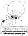
表示装置の射出瞳は、(特に全ての)コリメート光ビームの束(特にコーン)の断面、より一般には、表示装置が適切に使用される間、表示装置の全発光素子が光を放射する時に、表示装置から使用者の眼球の(特に網膜の)位置に出る(特に全ての)光線の束の断面として定義又は理解することができる。特に、表示装置の射出瞳内で、表示装置の光学素子により生成された各コリメート光ビームは、光点に投影されると考えることができ、このため、複数のコリメート光ビームは、表示装置の射出瞳内に光点パターンを形成することができる。 The exit pupil of the display device is a cross-section of (especially all) collimated light beam bundles (especially cones), more generally when all light emitting elements of the display device emit light during proper use of the display device. It can be defined or understood as a cross-section of a bundle of (especially all) rays that emerge from the display device to a position (especially in the retina) of the user's eye. In particular, each collimated light beam generated by the optical element of the display device within the exit pupil of the display device can be considered to be projected onto a light spot. A light spot pattern can be formed in the exit pupil.
表示装置の射出瞳の第1の部分は、例えば、表示装置が適切に使用される間、使用者の眼球が少なくとも一つの第1の観察方向に沿って注視する時に、この眼球の瞳が置かれる第1の空間部分を表すことができる。表示装置の射出瞳の第2の部分は、例えば、表示装置が適切に使用される間、使用者の眼球が第1の観察方向とは異なる少なくとも一つの第2の観察方向に沿って注視する時に、この眼球の瞳が置かれる、第1の空間部分と異なる第2の空間部分を表すことができる。 The first part of the exit pupil of the display device is placed, for example, when the eyeball of the user gazes along at least one first observation direction while the display device is used properly. The first spatial portion to be written can be represented. The second portion of the exit pupil of the display device, for example, gazes along the at least one second observation direction different from the first observation direction by the user's eye while the display device is used properly. Sometimes it can represent a second space portion different from the first space portion in which the pupil of the eyeball is placed.
発光素子は、発光素子が(特に可視)光を放射するオン状態と、発光素子が(特に可視)光を放射しないオフ状態との間で切り替え可能であることができる。例えば、光学素子は、少なくとも一つの第1の発光素子及び少なくとも一つの第2の発光素子と関連付けることができ、第1の及び第2の発光素子のそれぞれは、発光素子が光を放射するオフ状態と発光素子が光を放射しないオフ状態の間で切り替え可能とすることができる。この光学素子は、上記少なくとも一つの第1の発光素子により放射された光から少なくとも一つの第1のコリメート光ビームを形成し、上記少なくとも一つの第2の発光素子により放射された光から少なくとも一つの第2のコリメート光ビームを形成するように構成されることができる。この光学素子並びに第1の及び第2の発光素子は、上記少なくとも一つの第1のコリメート光ビームが表示装置の射出瞳の第1の部分を通過し、上記少なくとも一つの第2のコリメート光ビームが表示装置の射出瞳の第2の部分を通過するように構成及び配置されることができる。ここで、上記第2の部分は、上記第1の部分と異なり、特に、上記第1の部分と空間的に分断されたものである。第1の発光素子は、光学素子の光軸上に配置することができ、一方、第2の発光素子は、光学素子の光軸から逸れて配置されることができる。 The light emitting element can be switchable between an on state in which the light emitting element emits (especially visible) light and an off state in which the light emitting element does not emit (especially visible) light. For example, the optical element can be associated with at least one first light-emitting element and at least one second light-emitting element, each of the first and second light-emitting elements being turned off by which the light-emitting element emits light. It is possible to switch between a state and an off state in which the light emitting element does not emit light. The optical element forms at least one first collimated light beam from light emitted by the at least one first light emitting element, and at least one light from the light emitted by the at least one second light emitting element. Can be configured to form two second collimated light beams. The optical element and the first and second light emitting elements have the at least one first collimated light beam passing through a first portion of the exit pupil of the display device, and the at least one second collimated light beam. Can be configured and arranged to pass through the second portion of the exit pupil of the display device. Here, the second portion is different from the first portion, and is particularly spatially separated from the first portion. The first light emitting element can be disposed on the optical axis of the optical element, while the second light emitting element can be disposed off the optical axis of the optical element.
技術的効果及び利点として、使用者の眼球の瞳が表示装置の射出瞳の第1の部分(を表す第1の空間部分)に置かれた際の第1の観察方向に沿って、使用者の眼球が注視する時に、第1の発光素子のみをオン状態に設定し、第2の発光素子をオフ状態に設定することができる。一方で、使用者の眼球の瞳が表示装置の射出瞳の第2の部分(を表す第2の空間部分)に置かれた際の第2の観察方向に沿って、使用者の眼球が注視する時に、第2の発光素子のみをオン状態に設定し、第1の発光素子をオフ状態に設定することができる。言い換えると、特定の発光素子から放射される光が、例えば、この光が使用者の眼球の現行の観察方向では使用者の眼球に到達できないために不要である時に、この発光素子をオフ状態に設定することができる。これに関して、第1の及び第2の発光素子は、それぞれの発光素子をオン又はオフにすることでコリメート光ビームの出力先変更を可能にする複数のチャネルとして理解することができる。すなわち、光学素子と関連付けられた各発光素子により放射された光は、使用者の眼球の異なる観察方向で、使用者の眼球に到達することができる。従って、これらの発光素子により放射される光をより効果的に用いることができる。これにより、必要なパワーが低いエネルギー効率のよい表示装置が実現可能になる。結果として、この表示装置は改善された設計となる。更に、表示装置から出るコリメート光ビームの出力先変更スキームが、一つの各光学素子と関連付けられた少数の(例えば2つ又は3つの)発光素子でも実現可能であるため、簡素な設計のまま、この出力先変更スキームを機能させることができる。例えば、光が使用者の眼球に直接入ることを防ぐために、発光素子から放射される光を遮断する付加的なマスクを各発光素子に設ける場合、これらのマスクの数及び/又はこれらのマスクの大きさを小さく維持することもでき、これにより、表示装置の設計を更に簡素化することができる。 As a technical effect and advantage, along the first viewing direction when the pupil of the user's eyeball is placed on the first part (representing first spatial part) of the exit pupil of the display device, the user When the eyeball gazes, only the first light emitting element can be set to the on state and the second light emitting element can be set to the off state. On the other hand, the user's eyeball gazes along the second observation direction when the pupil of the user's eyeball is placed on the second portion (representing the second space portion) of the exit pupil of the display device. In doing so, only the second light emitting element can be set to the on state, and the first light emitting element can be set to the off state. In other words, when light emitted from a particular light emitting element is not needed because, for example, this light cannot reach the user's eyeball in the current viewing direction of the user's eyeball, the light emitting element is turned off. Can be set. In this regard, the first and second light emitting elements can be understood as a plurality of channels that enable changing the output destination of the collimated light beam by turning each light emitting element on or off. That is, the light emitted by each light emitting element associated with the optical element can reach the user's eyeball in different viewing directions of the user's eyeball. Therefore, the light emitted by these light emitting elements can be used more effectively. This makes it possible to realize an energy efficient display device with low required power. As a result, this display device has an improved design. Furthermore, since the output redirection scheme of the collimated light beam emitted from the display device can be realized with a small number of (for example, two or three) light emitting elements associated with each optical element, the design remains simple. This output destination change scheme can function. For example, if each light emitting element is provided with an additional mask that blocks light emitted from the light emitting elements to prevent light from directly entering the user's eyeball, the number of these masks and / or The size can also be kept small, which can further simplify the design of the display device.
表示装置は、使用者の眼球の瞳の像を取得する像取得装置を具備することができる。この像取得装置は、特には表示装置の射出瞳の位置に対する、使用者の眼球の瞳の位置を表す位置信号を生成するように構成されることができる。従って、この像取得装置により、使用者の眼球の瞳の位置を追跡することが可能になる。この点で、像取得装置はアイトラッカーとみなすことができる。像取得装置は、スタンドアロンの(例えばマイクロ)カメラであってもよく、例えば、表示装置の側に位置してもよく、又はそれ自身が表示装置に埋め込まれていてもよい。また、表示装置は、制御ユニットを具備することができる。この制御ユニットは、像取得装置により生成された位置信号に基づき、発光素子を切り替えるように構成されることができる。例えば、制御ユニットは、使用者の眼球の瞳が表示装置の射出瞳の第1の部分(を表す第1の空間部分)に位置する時に、第1の発光素子をオン状態に設定し、及び/又は、第2の発光素子をオフ状態に設定し、及び/又は、使用者の眼球の瞳が表示装置の射出瞳の第2の部分(を表す第2の空間部分)に位置する時に、第1の発光素子をオフ状態に設定し、及び/又は、第2の発光素子をオン状態に設定するように構成されることができる。 The display device may include an image acquisition device that acquires an image of a pupil of a user's eyeball. The image acquisition device can be configured to generate a position signal representing the position of the pupil of the user's eyeball, in particular relative to the position of the exit pupil of the display device. Therefore, this image acquisition device can track the position of the pupil of the user's eyeball. In this respect, the image acquisition device can be regarded as an eye tracker. The image acquisition device may be a stand-alone (eg, micro) camera, for example, may be located on the side of the display device, or may itself be embedded in the display device. In addition, the display device can include a control unit. The control unit can be configured to switch the light emitting elements based on the position signal generated by the image acquisition device. For example, the control unit sets the first light emitting element to an on state when the pupil of the user's eyeball is located in a first portion (representing a first space portion) of the exit pupil of the display device; and And / or when the second light emitting element is set to the OFF state and / or when the pupil of the user's eyeball is located in the second portion (representing the second spatial portion) of the exit pupil of the display device, It may be configured to set the first light emitting element to an off state and / or to set the second light emitting element to an on state.
技術的効果及び利点として、第1の及び第2の発光素子のうち一方の発光素子のみをオン状態に設定して、関連付けられた光学素子により、放射された光を現行の観察方向で使用者の眼球の瞳へ実際に向けることができ、一方で、第1の及び第2の発光素子のうちもう一方の発光素子をオフ状態に設定して、関連付けられた光学素子により、放射された光が現行の観察方向で使用者の眼球の瞳に向けられないようにすることができる。言い換えると、特定の発光素子から放射される光が、例えば、この光が使用者の眼球の現行の観察方向では使用者の眼球に到達できないために不要である時に、この発光素子をオフ状態に設定することができる。従って、使用者の眼球に到達できない光が全く生成されなくなる。そのため、発光素子により放射される光をより効果的に用いることができる。これにより、必要なパワーが低いエネルギー効率のよい表示装置が実現可能になる。結果として、この表示装置は改善された設計となる。 As a technical effect and advantage, only one of the first and second light emitting elements is set to the on state, and the emitted light is transmitted to the user in the current observation direction by the associated optical element. While the other light-emitting element of the first and second light-emitting elements is set to the OFF state, and the light emitted by the associated optical element Can be prevented from being directed to the pupil of the user's eyeball in the current viewing direction. In other words, when light emitted from a particular light emitting element is not needed because, for example, this light cannot reach the user's eyeball in the current viewing direction of the user's eyeball, the light emitting element is turned off. Can be set. Therefore, no light that cannot reach the user's eyeball is generated. Therefore, the light emitted from the light emitting element can be used more effectively. This makes it possible to realize an energy efficient display device with low required power. As a result, this display device has an improved design.
表示装置は、表示装置が適切に使用される位置に使用者の眼球が置かれるように、使用者の眼球に対して表示装置を配置するように構成された、ガラスフレームや眼鏡フレーム等の位置決め装置を具備することができる。より具体的には、位置決め装置を用いることで、表示装置の位置及び方位に対する使用者の顔又は頭の位置及び方位を定めることができる。位置決め装置は、表示装置の射出瞳(を表す空間部分)内に使用者の眼球の瞳を配置するように構成されることができる。 The display device is configured to position the display device with respect to the user's eyeball so that the user's eyeball is placed at a position where the display device is appropriately used, such as a glass frame or a spectacle frame. An apparatus can be provided. More specifically, the position and orientation of the user's face or head relative to the position and orientation of the display device can be determined by using the positioning device. The positioning device can be configured to place the pupil of the user's eyeball within the exit pupil of the display device.
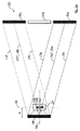
複数の光学素子及び発光素子のアレイは、コリメート光ビームの少なくとも一つの第1の一部分が表示装置の射出瞳の少なくとも一つの第1の部分を通過し、上記コリメート光ビームの第1の一部分と異なる、コリメート光ビームの少なくとも一つの第2の一部分が、上記表示装置の射出瞳の第1の部分と異なる表示装置の射出瞳の少なくとも一つの第2の部分を通過するように、構成及び配置されることができる。一般に、複数の光学素子は、少なくとも一つの第1の光学素子及び少なくとも一つの第2の光学素子を含むことができる。第1の及び第2の光学素子は、少なくとも一つの発光素子と関連付けることができ、第1の光学素子は、関連付けられた発光素子から光を受け、該受けられた光から第1のコリメート光ビームを形成するように構成され、第2の光学素子は、関連付けられた発光素子から光を受け、該受けられた光から第2のコリメート光ビームを形成するように構成されることができる。第1の及び第2の光学素子並びに関連付けられた発光素子は、第1のコリメート光ビームが表示装置の射出瞳の第1の部分を通過し、第2のコリメート光ビームが表示装置の射出瞳の第2の部分を通過するように構成及び配置されることができ、上記第2の部分は、上記第1の部分と異なり、特に、上記第1の部分と空間的に分断される。 The array of optical elements and light emitting elements includes at least one first portion of the collimated light beam passing through at least one first portion of the exit pupil of the display device, and the first portion of the collimated light beam; Configuration and arrangement such that at least one second portion of the different collimated light beam passes through at least one second portion of the display device exit pupil different from the first portion of the display device exit pupil. Can be done. In general, the plurality of optical elements can include at least one first optical element and at least one second optical element. The first and second optical elements can be associated with at least one light emitting element, the first optical element receiving light from the associated light emitting element and generating first collimated light from the received light. The second optical element may be configured to form a beam, and the second optical element may be configured to receive light from the associated light emitting element and form a second collimated light beam from the received light. The first and second optical elements and the associated light emitting elements have a first collimated light beam passing through a first portion of the display apparatus exit pupil and a second collimated light beam passing through the display apparatus exit pupil. The second part is different from the first part and in particular is spatially separated from the first part.
技術的効果及び利点として、第1の及び第2の光学素子と関連付けられた発光素子により放射される光は、眼球が表示装置の射出瞳の第1の部分(を表す第1の空間部分)に置かれた時に、使用者の眼球の瞳に向けられるだけでなく、眼球が表示装置の射出瞳の第2の部分(を表す第2の空間部分)に置かれた時にも、使用者の眼球の瞳に向けられる。従って、第1の及び第2の光学素子と関連付けられた発光素子により放射される光は、使用者の眼球の異なる観察方向で、使用者の眼球に到達することができる。言い換えると、表示装置から出たコリメート光ビームの全体の一部は、常に、使用者の眼球の瞳を通過することができる。更に、表示装置の射出瞳内で、少なくとも一つの第1のコリメート光ビームは、(特に、眼球の角膜等の眼球表面上の)少なくとも一つの第1の光点に投影されると考えることができ、少なくとも一つの第2のコリメート光ビームは、(特に、眼球の角膜等の上記と同じ眼球表面上の)少なくとも一つの第2の光点に投影されると考えることができ、この第1の及び第2の光点は、表示装置の射出瞳内で、特には重なる又は重ならない方法で、互いに対して空間的に分離されており、これにより、光点パターンが形成される。従って、表示装置の射出瞳内で、少なくとも二つの光点は、使用者の眼球の少なくとも二つの異なる観察方向に対応する、使用者の眼球の瞳の少なくとも二つの異なる位置を包含することができる。そのため、使用者は、使用者の眼球の異なる観察方向について、表示装置により作り出された像を見ることが可能になる。これにより、大きな視野を有する表示装置の実現が可能になる。結果として、この表示装置は改善された設計となる。 As a technical effect and advantage, the light emitted by the light emitting elements associated with the first and second optical elements is such that the eyeball is a first portion of the exit pupil of the display device (representing a first spatial portion). Not only to be directed to the pupil of the user's eyeball, but also when the eyeball is placed on the second portion (representing the second spatial portion) of the exit pupil of the display device Aimed at the eyes of the eyeball. Accordingly, light emitted by the light emitting elements associated with the first and second optical elements can reach the user's eyeball in different viewing directions of the user's eyeball. In other words, a part of the entire collimated light beam emitted from the display device can always pass through the pupil of the user's eyeball. Further, within the exit pupil of the display device, at least one first collimated light beam may be projected onto at least one first light spot (especially on an eyeball surface such as the cornea of the eyeball). And at least one second collimated light beam can be considered to be projected onto at least one second light spot (especially on the same eyeball surface as described above, such as the cornea of the eyeball). The and second light spots are spatially separated from one another in the exit pupil of the display device, in particular in an overlapping or non-overlapping manner, thereby forming a light spot pattern. Thus, within the exit pupil of the display device, the at least two light spots can encompass at least two different positions of the user's eyeball pupil corresponding to at least two different viewing directions of the user's eyeball. . Therefore, the user can see images created by the display device for different viewing directions of the user's eyeball. As a result, a display device having a large field of view can be realized. As a result, this display device has an improved design.
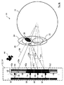
これに代わって、又はこれに加えて、第1の及び第2の光学素子並びに関連付けられた少なくとも一つの発光素子は、表示装置が適切に使用される間、第1のコリメート光ビームが中心窩を含む眼球の網膜の「中心」部に結像され、第2のコリメート光ビームが中心窩から逸れた網膜の「周辺」部に結像されるように構成及び配置されることができる。これに関して、少なくとも一つの第1の光学素子は「中心」光学素子と呼ばれ、少なくとも一つの第2の光学素子は「周辺」光学素子と呼ばれ、少なくとも一つの第1のコリメート光ビームは「中心」コリメート光ビームと呼ばれ、及び/又は少なくとも一つの第2のコリメート光ビームは「周辺」コリメート光ビームと呼ばれ得る。 Alternatively or in addition thereto, the first and second optical elements and the associated at least one light emitting element are arranged such that the first collimated light beam is foveated during proper use of the display device. And the second collimated light beam can be constructed and arranged to be imaged on the “peripheral” portion of the retina off the fovea. In this regard, at least one first optical element is referred to as a “center” optical element, at least one second optical element is referred to as a “peripheral” optical element, and at least one first collimated light beam is “ The “center” collimated light beam may be referred to and / or the at least one second collimated light beam may be referred to as the “peripheral” collimated light beam.
技術的効果及び利点として、第1の(中心)コリメート光ビームは、表示装置の射出瞳内で比較的高い分解能を有する中心窩を含む網膜の中心部により目視することができる、(特に、眼球の角膜等の眼球表面上の)少なくとも一つの(中心)光点に投影されると考えることができる。一方で、第2の(周辺)コリメート光ビームは、表示装置の射出瞳内で比較的低い分解能を有する、中心窩から逸れた網膜の周辺部により目視することができる、少なくとも一つの(周辺)光点に投影されると考えることができる。これにより、中心窩の分解能に適合された光点パターンを生成する表示装置が実現可能になる。結果として、この表示装置は改善された設計となる。 As a technical effect and advantage, the first (center) collimated light beam can be viewed by the central part of the retina including the fovea with a relatively high resolution in the exit pupil of the display device (in particular the eyeball). Can be thought of as projected onto at least one (center) light spot (on the surface of the eye, such as the cornea). On the other hand, the second (peripheral) collimated light beam has at least one (peripheral) visible through the periphery of the retina off the fovea, which has a relatively low resolution in the exit pupil of the display device It can be thought of as being projected onto a light spot. Thereby, a display device that generates a light spot pattern adapted to the resolution of the fovea can be realized. As a result, this display device has an improved design.
これに代わって、又はこれに加えて、複数の光学素子は、少なくとも一つの発光素子と関連付けられた少なくとも一つの第1の光学素子及び少なくとも一つの第2の光学素子を含むことができる。この第1の及び第2の光学素子は、関連付けられた少なくとも一つの発光素子から光を受け、該受けられた光から少なくとも一つの第1のコリメート光ビーム及び少なくとも一つの第2のコリメート光ビームを形成するように構成されることができ、この第1の及び第2の光学素子並びに関連付けられた少なくとも一つの発光素子は、特には第1の及び第2のコリメート光ビームが互いに対して少なくとも部分的に重なるような方法で、第1の及び第2のコリメート光ビームが互いに対して実質的に平行に表示装置から出るように、構成及び配置されることができる。 Alternatively or in addition, the plurality of optical elements can include at least one first optical element and at least one second optical element associated with at least one light emitting element. The first and second optical elements receive light from the associated at least one light emitting element and from the received light at least one first collimated light beam and at least one second collimated light beam. The first and second optical elements and the associated at least one light emitting element, in particular the first and second collimated light beams are at least relative to each other. In a partially overlapping manner, the first and second collimated light beams can be configured and arranged to exit the display device substantially parallel to each other.
技術的効果及び利点として、第1の及び第2のコリメート光ビームの両方が、表示装置の射出瞳内で使用者の眼球により目視することができる、(特に、眼球の角膜等の眼球表面上の)少なくとも一つの共通の光点に投影されると考えることができる。結果として、この共通の光点(すなわち、同一の空間部分)は、二つ以上の異なる色を含むことができる。これは、例えば、発光素子のアレイが、少なくとも一つの第1の色の光を放射する少なくとも一つの第1の発光素子と、上記少なくとも一つの第1の色と異なる少なくとも一つの第2の色の光を放射する少なくとも一つの第2の発光素子とを含み、上記第1の光学素子が少なくとも一つの第1の発光素子とのみ関連付けられ、上記第2の光学素子が少なくとも一つの第2の発光素子とのみ関連付けられ、上記第1の光学素子が、第1の発光素子から光を受け、該受けられた光から第1のコリメート光ビームを形成するように構成され、上記第2の光学素子が、第2の発光素子から光を受け、該受けられた光から第2のコリメート光ビームを形成するように構成された場合である。これにより、使用者は、表示装置により生成された色付き像を知覚することができ、また、この色付き像は、第1の及び第2の発光素子により放射される少なくとも二つの異なる色の全てが同一の共通の光点に同時に存在するため、高い解像度を有する。従って、表示装置は高品質の像を提供することが可能になる。結果として、この表示装置は改善された設計となる。 As a technical effect and advantage, both the first and second collimated light beams can be viewed by the user's eyeball in the exit pupil of the display device (especially on the eyeball surface such as the cornea of the eyeball). Can be considered to be projected onto at least one common light spot. As a result, this common light spot (ie, the same spatial portion) can include two or more different colors. For example, the array of light emitting elements includes at least one first light emitting element that emits light of at least one first color, and at least one second color different from the at least one first color. At least one second light-emitting element that emits the light, wherein the first optical element is associated only with at least one first light-emitting element, and the second optical element is at least one second light-emitting element. Associated with the light emitting element only, wherein the first optical element is configured to receive light from the first light emitting element and form a first collimated light beam from the received light, wherein the second optical element This is the case when the element is configured to receive light from the second light emitting element and form a second collimated light beam from the received light. This allows the user to perceive a colored image generated by the display device, and this colored image is the result of all of the at least two different colors emitted by the first and second light emitting elements. Since they are simultaneously present in the same common light spot, they have a high resolution. Therefore, the display device can provide a high-quality image. As a result, this display device has an improved design.
第1の光学素子の焦点距離は、第2の光学素子の焦点距離より大きくすることができる。 The focal length of the first optical element can be greater than the focal length of the second optical element.
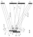
技術的効果及び利点として、第1の光学素子が表示装置の第1の層に配置され、第2の光学素子が表示装置の第2の層に配置され、関連付けられた少なくとも一つの発光素子が表示装置の第3の層に配置された3層構成を実現することができる。上記第3の層は、第1の及び第2の光学素子の焦点面に一致させることができる。また、第1の光学素子が第2の光学素子よりも発光素子から離れて配置されていても、第1の光学素子が、そのより長い焦点距離により、なおも発光素子からの光を平行化することができるため、上記第2の層は上記第1の層と上記第3の層の間に配置されることができる。更に、このような3層構成では、第2の光学素子の焦点距離がより短いため、一方では、使用者の眼球で、発光素子の(特に、横断面)像の倍率を増大することが可能であり、他方では、発光素子からの光を受ける集光角(開口数)を増大することが可能であり、これにより偏向角も増大するため、より大きな射出瞳及び/又は視野が可能になる。これにより、大きな視野を有する表示装置が実現可能になる。また、第1の光学素子が中心光学素子であり、第2の光学素子が周辺光学素子である場合、第2の光学素子の倍率がより大きいことで、眼球の角膜等の眼球表面上の光点パターンの解像度が低くなり得るが、第2の光点は、そもそも低い分解能を有する、中心窩から逸れた網膜の周辺部により目視されるため、この低解像度は問題にはならず、むしろ理にかなったものとなる。これにより、中心窩の分解能に適合された光点パターンを生成する表示装置が実現可能になる。結果として、この表示装置は改善された設計となる。 As a technical effect and advantage, the first optical element is disposed in the first layer of the display device, the second optical element is disposed in the second layer of the display device, and at least one associated light emitting element is provided. A three-layer configuration arranged in the third layer of the display device can be realized. The third layer can coincide with the focal planes of the first and second optical elements. Even if the first optical element is arranged farther from the light emitting element than the second optical element, the first optical element still collimates the light from the light emitting element due to its longer focal length. Therefore, the second layer can be disposed between the first layer and the third layer. Furthermore, in such a three-layer configuration, the focal length of the second optical element is shorter, and on the other hand, it is possible to increase the magnification of the image of the light emitting element (especially the cross section) with the user's eyeball. On the other hand, it is possible to increase the condensing angle (numerical aperture) for receiving light from the light emitting element, thereby increasing the deflection angle, thereby allowing a larger exit pupil and / or field of view. . Thereby, a display device having a large visual field can be realized. Further, when the first optical element is a central optical element and the second optical element is a peripheral optical element, the light on the surface of the eyeball such as the cornea of the eyeball can be obtained because the magnification of the second optical element is larger. Although the resolution of the point pattern can be low, this low resolution is not a problem because the second light spot is viewed by the periphery of the retina off the fovea, which has a low resolution in the first place, rather it is reasonable. It will be a good one. Thereby, a display device that generates a light spot pattern adapted to the resolution of the fovea can be realized. As a result, this display device has an improved design.
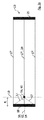
第1の光学素子は、第1の層に配置されることができ、第2の光学素子は第2の層に配置されることができ、関連付けられた少なくとも一つの発光素子は第3の層に配置されることができ、上記第2の層は、上記第1の層と上記第3の層の間に配置されることができる。これに関して、少なくとも一つの第1の光学素子は「第1の層の」光学素子、少なくとも一つの第2の光学素子は「第2の層の」光学素子と呼ばれ得る。 The first optical element can be disposed on the first layer, the second optical element can be disposed on the second layer, and the associated at least one light emitting element is the third layer. The second layer may be disposed between the first layer and the third layer. In this regard, at least one first optical element may be referred to as a “first layer” optical element and at least one second optical element may be referred to as a “second layer” optical element.
技術的効果及び利点として、既に上述した利点及び効果に加えて、第1の及び第2の(層の)光学素子は、表示装置の同一の層に配置されない。このため、各層の光学素子の密度を減少させることでき、光学素子の高密度の配置を避けることができる。また、これにより、光学素子を分離して配置することが可能となり、そのため、光学素子の配置の自由度が増す。従って、光学素子のより簡素な配置、曳いては表示装置のより容易な製造が可能になる。結果として、この表示装置は改善された設計となる。 As a technical effect and advantage, in addition to the advantages and effects already described above, the first and second (layered) optical elements are not arranged in the same layer of the display device. For this reason, the density of the optical element of each layer can be reduced, and the high-density arrangement | positioning of an optical element can be avoided. This also makes it possible to arrange the optical elements separately, thereby increasing the degree of freedom in arranging the optical elements. Therefore, a simpler arrangement of the optical elements, that is, easier manufacture of the display device is possible. As a result, this display device has an improved design.
第1の光学素子の焦点面及び第2の光学素子の焦点面は、共通の焦点面に配置されることができ、関連付けられた少なくとも一つの発光素子は、上記共通の焦点面に配置されることができる。 The focal plane of the first optical element and the focal plane of the second optical element can be disposed on a common focal plane, and the associated at least one light emitting element is disposed on the common focal plane. be able to.
更なる技術的効果及び利点として、既に上述した利点及び効果に加えて、第1の光学素子が第2の光学素子よりも発光素子から離れて配置されていても、第1の及び第2の光学素子の両方は、なおも少なくとも一つの発光素子からの光を平行化することができる。 As a further technical effect and advantage, in addition to the advantages and effects already mentioned above, the first and second optical elements can be arranged even if the first optical element is arranged farther from the light emitting element than the second optical element. Both optical elements can still collimate light from at least one light emitting element.
表示装置は、第1の及び第2の光学素子の両方と関連付けられた発光素子により放射される光を遮断するフィルターを具備することができ、このフィルターは、上記第1の光学素子と上記第2の光学素子の間に配置されることができる。より具体的には、このフィルターは、第1の光学素子が配置された第1の層と、第2の光学素子が配置された第2の層との間に配置された層に配置されることができる。特に、このようなフィルターは、第1の及び/又は第2の光学素子に設けることができる。 The display device can comprise a filter that blocks light emitted by the light emitting element associated with both the first and second optical elements, the filter comprising the first optical element and the first optical element. It can be arranged between two optical elements. More specifically, the filter is disposed in a layer disposed between the first layer in which the first optical element is disposed and the second layer in which the second optical element is disposed. be able to. In particular, such a filter can be provided in the first and / or second optical element.
技術的効果及び利点として、例えば第1の光学素子により既に形成され、第2の光学素子に向かって伝播する光線又はコリメート光ビームが、第1の光学素子と第2の光学素子の間に配置されたフィルターにより遮断されることで、この光線又はコリメート光ビームが第2の光学素子に到達し、それにより第2の光学素子により攪乱される(例えば、広げられたり方向を変えられる)ことが防止される。従って、遮断された光は、制御できない方法で及び/又は望まない方向に散乱されない。そのため、攪乱されたコリメート光ビームにより望まない迷光が生成されることなく、表示装置の明確に定められた光放射が可能になる。結果として、この表示装置は改善された設計となる。 As a technical effect and advantage, for example, a light beam or collimated light beam already formed by the first optical element and propagating towards the second optical element is arranged between the first optical element and the second optical element. The light beam or collimated light beam reaches the second optical element and is thereby disturbed (e.g., spread or redirected) by the second optical element by being interrupted by the filtered filter. Is prevented. Thus, the blocked light is not scattered in an uncontrollable manner and / or in unwanted directions. This allows a well-defined light emission of the display device without unwanted stray light being generated by the disturbed collimated light beam. As a result, this display device has an improved design.
第1の及び第2の光学素子が少なくとも一つの発光素子と関連付けられ、上記第1の光学素子が、関連付けられた少なくとも一つの発光素子から光を受け、該受けられた光から少なくとも一つの第1のコリメート光ビームを形成するように構成され、上記第2の光学素子が、関連付けられた少なくとも一つの発光素子から光を受け、該受けられた光から少なくとも一つの第2のコリメート光ビームを形成するように構成されることを実現する二つの実施可能な選択肢が存在する。 First and second optical elements are associated with at least one light emitting element, and the first optical element receives light from the associated at least one light emitting element and at least one first light from the received light. The second optical element receives light from the associated at least one light emitting element and generates at least one second collimated light beam from the received light. There are two possible options for realizing that it is configured to form.
発光素子のアレイは、少なくとも一つの第1の色の光を放射する少なくとも一つの第1の発光素子と、上記少なくとも一つの第1の色と異なる少なくとも一つの第2の色の光を放射する少なくとも一つの第2の発光素子とを含むことができる。第1の光学素子は、上記少なくとも一つの第1の発光素子とのみ関連付けることができ、第2の光学素子は、上記少なくとも一つの第2の発光素子とのみ関連付けることができ、上記第1の光学素子は、上記第1の発光素子から光を受け、該受けられた光から第1のコリメート光ビームを形成するように構成され、上記第2の光学素子は、上記第2の発光素子から光を受け、該受けられた光から第2のコリメート光ビームを形成するように構成されることができる。 The array of light emitting elements emits at least one first light emitting element that emits light of at least one first color, and emits light of at least one second color different from the at least one first color. And at least one second light emitting element. The first optical element can be associated only with the at least one first light emitting element, and the second optical element can be associated only with the at least one second light emitting element, and the first optical element can be associated with the first optical element. The optical element is configured to receive light from the first light emitting element and form a first collimated light beam from the received light, and the second optical element is formed from the second light emitting element. It can be configured to receive light and form a second collimated light beam from the received light.
技術的効果及び利点として、第1の光学素子は、少なくとも一つの第2の発光素子とは全く関連付けられず、例えば、第2の発光素子により放射される光に対して透明となる。逆もまた同様に、第2の光学素子は、少なくとも一つの第1の発光素子とは全く関連付けられず、例えば、第1の発光素子により放射される光に対して透明となる。この場合、第1の光学素子は、第2の光学素子により形成される第2のコリメート光ビームを攪乱できず、逆もまた同様に、第2の光学素子は、第1の光学素子により形成される第1のコリメート光ビームをやはり攪乱できない。従って、上述したようなフィルターがなくてもよく、あるいは不要である。これにより、表示装置の軽量化及び小型化設計が実現可能になる。また、第1の光学素子の光軸と第2の光学素子の光軸が互いに対して傾いており、及び/又は、第1の光学素子の参照軸と第2の光学素子の参照軸が互いに対して平行であり、これにより(以下で更に説明するように)表示装置の構成の自由度が増していても、第1の及び第2のコリメート光ビームを、射出瞳の異なる第1の及び第2の部分に通過させることがなおも可能である。結果として、この表示装置は改善された設計となる。 As a technical effect and advantage, the first optical element is not associated with the at least one second light emitting element at all and is, for example, transparent to the light emitted by the second light emitting element. Vice versa, the second optical element is not at all associated with at least one first light emitting element and is, for example, transparent to the light emitted by the first light emitting element. In this case, the first optical element cannot disturb the second collimated light beam formed by the second optical element, and vice versa, the second optical element is formed by the first optical element. The first collimated light beam that is produced cannot still be disturbed. Therefore, the filter as described above may be omitted or unnecessary. This makes it possible to realize a lighter and smaller design of the display device. In addition, the optical axis of the first optical element and the optical axis of the second optical element are inclined with respect to each other, and / or the reference axis of the first optical element and the reference axis of the second optical element are mutually The first and second collimated light beams are coupled to the first and second collimated light beams with different exit pupils even though they are parallel to each other (as will be further described below). It is still possible to pass through the second part. As a result, this display device has an improved design.
これに代わって、第1の及び第2の光学素子は、少なくとも一つの共通の発光素子と関連付けられてもよく、上記第1の光学素子は、上記共通の発光素子から光を受け、該受けられた光から第1のコリメート光ビームを形成するように構成され、上記第2の光学素子は、共通の発光素子から光を受け、該受けられた光から第2のコリメート光ビームを形成するように構成されてもよい。 Alternatively, the first and second optical elements may be associated with at least one common light emitting element, and the first optical element receives light from the common light emitting element and receives the light. The second optical element is configured to form a first collimated light beam from the received light, and the second optical element receives light from a common light emitting element and forms a second collimated light beam from the received light. It may be configured as follows.
技術的効果及び利点として、第1の及び第2の光学素子の両方が、同一の共通の発光素子から、それぞれのコリメート光ビームを形成することができる。このように、第1の及び第2の光学素子は、同一の共通の発光素子を共有する。これにより、発光素子の数を減らすことができる。従って、表示装置の軽量化、小型化、及びエネルギー効率のよい設計が可能になる。結果として、この表示装置は改善された設計となる。 As a technical effect and advantage, both the first and second optical elements can form respective collimated light beams from the same common light emitting element. Thus, the first and second optical elements share the same common light emitting element. Thereby, the number of light emitting elements can be reduced. Therefore, the display device can be reduced in weight, size, and energy-efficient design. As a result, this display device has an improved design.
第1の及び第2の光学素子のうち少なくとも一つは、その光学素子の光軸及びその光学素子の参照軸が互いに対して傾くように構成されることができる。 At least one of the first and second optical elements may be configured such that the optical axis of the optical element and the reference axis of the optical element are tilted with respect to each other.
技術的効果及び利点として、関連付けられた発光素子が光軸上に配置された場合、コリメート光ビームがこの関連付けられた発光素子を通過せずに参照軸に沿って光学素子から出るような方法で、光軸が参照軸に対して傾くように、光学素子を構成することができる。これにより、コリメート光ビームは、発光素子により少なくとも部分的に再吸収されずに、及び/又は、制御できない方法で及び/又は望まない方向に散乱されずに、表示装置から出ることができる。従って、コリメート光ビームを攪乱することで望まない迷光が生成されることなく、表示装置は、エネルギー効率がよく、明確に定められた光放射特性を有することが可能になる。結果として、この表示装置は改善された設計となる。 As a technical effect and advantage, when the associated light emitting element is arranged on the optical axis, the collimated light beam does not pass through the associated light emitting element but exits the optical element along the reference axis. The optical element can be configured such that the optical axis is inclined with respect to the reference axis. This allows the collimated light beam to exit the display device without being at least partially reabsorbed by the light emitting element and / or in an uncontrollable manner and / or undesirably scattered. Therefore, the display device can be energy efficient and have well-defined light emission characteristics without generating unwanted stray light by disturbing the collimated light beam. As a result, this display device has an improved design.
第1の及び第2の光学素子は、第1の光学素子の参照軸及び第2の光学素子の参照軸が互いに対して傾くように構成されることができる。 The first and second optical elements can be configured such that the reference axis of the first optical element and the reference axis of the second optical element are inclined with respect to each other.
技術的効果及び利点として、第1のコリメート光ビームを表示装置の射出瞳の第1の部分に通過させ、第2のコリメート光ビームを、上記第1の部分と異なり、特には上記第1の部分と空間的に分断された、表示装置の射出瞳の第2の部分に通過させること、及び/又は、第1のコリメート光ビームを、中心窩を含む眼球の網膜の中心部に結像し、第2のコリメート光ビームを、中心窩から逸れた網膜の周辺部に結像することを容易に達成することができる。より一般には、第1の光学素子の参照軸と第2の光学素子の参照軸の間の角度を設定することによって、第1の及び第2のコリメート光ビームが、特にはコリメート光ビームが交差さえせずに(すなわち、コリメート光ビームが、まず収束し、次に交差し、最終的に分かれていくのではなく、第1の及び第2の光学素子から出た直後に分かれ始めて)、互いに分かれていくように、第1の及び第2の光学素子を構成することができる。これにより、大きな視野を有する表示装置が実現可能になる。また、第1の光学素子が表示装置の第1の感光乳剤領域に記録された第1のホログラム光学素子であり、第2の光学素子も省重量及び省スペースな第1の感光乳剤領域に記録された第2のホログラム光学素子であったとしても、これらの参照軸を互いに対して傾けることで、第1の及び第2のコリメート光ビームを射出瞳の異なる第1の及び第2の部分に通過させることがなおも可能である。これにより、大きな視野を有する表示装置の軽量化及び小型化設計が実現可能になる。結果として、この表示装置は改善された設計となる。 As a technical effect and advantage, the first collimated light beam is passed through the first part of the exit pupil of the display device and the second collimated light beam is different from the first part, in particular the first part. Passing through a second part of the exit pupil of the display device that is spatially separated from the part and / or imaging the first collimated light beam at the center of the retina of the eyeball including the fovea. The second collimated light beam can easily be imaged on the periphery of the retina off the fovea. More generally, by setting the angle between the reference axis of the first optical element and the reference axis of the second optical element, the first and second collimated light beams, in particular the collimated light beams intersect. Without even (i.e., the collimated light beams begin to diverge immediately after exiting the first and second optical elements, rather than first converging, then intersecting, and finally separating). The first and second optical elements can be configured to be separated. Thereby, a display device having a large visual field can be realized. Further, the first optical element is a first hologram optical element recorded in the first photosensitive emulsion area of the display device, and the second optical element is also recorded in the first photosensitive emulsion area which is weight-saving and space-saving. Even if the second holographic optical element is made, by tilting these reference axes with respect to each other, the first and second collimated light beams are directed to the first and second portions having different exit pupils. It is still possible to pass through. This makes it possible to realize a lighter and smaller design of a display device having a large field of view. As a result, this display device has an improved design.
これに代わって、第1の及び第2の光学素子は、第1の光学素子の参照軸及び第2の光学素子の参照軸が互いに対して平行となるように、又は一致さえするように構成されてもよい。 Alternatively, the first and second optical elements are configured such that the reference axis of the first optical element and the reference axis of the second optical element are parallel or even coincident with each other. May be.
技術的効果及び利点として、第1の及び第2のコリメート光ビームが互いに対して実質的に平行に表示装置から出ることを容易に達成することができる。またこれは、第1の及び第2の光学素子のうち少なくとも一つが、その光軸と参照軸とが互いに対して傾くようにも構成された場合でも、また、具体的には第1の光学素子の光軸上に二つの発光素子のうち一方を配置し、第2の光学素子の光軸上に二つの発光素子のうち他方を配置することで、第1の及び第2の光学素子が二つの異なる、空間的に分離された(またそれにより低密度で配置された)発光素子から光を受ける場合でも可能である。言い換えると、第1の及び第2の光学素子の光軸は互いに対して傾いているが、第1の及び第2の光学素子の参照軸は平行又は一致している場合、関連付けられた第1の及び第2の発光素子は、例えば参照軸に垂直な方向に空間的に分離された方法で容易に配置されることができ、また、第1の及び第2の発光素子により放射された二色の光は、参照軸が平行又は一致しているため、なおも同一の共通の光点に同時に到達することができる。従って、発光素子は、例えば参照軸に沿った方向に積層される必要がない。これにより、発光素子の簡素な配置や、表示装置のより自由度の高い構成が可能になる。結果として、この表示装置は改善された設計となる。 As a technical effect and advantage, it can easily be achieved that the first and second collimated light beams exit the display device substantially parallel to each other. This is also true when at least one of the first and second optical elements is configured such that the optical axis and the reference axis are inclined with respect to each other, and more specifically, the first optical element. By arranging one of the two light emitting elements on the optical axis of the element and arranging the other of the two light emitting elements on the optical axis of the second optical element, the first and second optical elements are It is also possible to receive light from two different, spatially separated (and thereby arranged at a low density) light emitting elements. In other words, if the optical axes of the first and second optical elements are tilted with respect to each other, but the reference axes of the first and second optical elements are parallel or coincident, the associated first The second and second light emitting elements can be easily arranged, for example, in a spatially separated manner in a direction perpendicular to the reference axis, and the two light emitting elements emitted by the first and second light emitting elements. Colored light can still reach the same common light spot simultaneously because the reference axes are parallel or coincident. Therefore, the light emitting elements do not need to be stacked in a direction along the reference axis, for example. Thereby, a simple arrangement of the light emitting elements and a configuration with a higher degree of freedom of the display device are possible. As a result, this display device has an improved design.
第1の光学素子は、表示装置の第1の感光乳剤領域に記録された第1のホログラム光学素子とすることができ、第2の光学素子も、上記第1の感光乳剤領域に記録された第2のホログラム光学素子とすることができる。 The first optical element can be a first hologram optical element recorded in the first photosensitive emulsion area of the display device, and the second optical element is also recorded in the first photosensitive emulsion area. It can be set as a 2nd hologram optical element.
技術的効果及び利点として、二つの光学素子を表すために、同一の感光乳剤領域を用いることができる。これにより、表示装置の小型化及び省スペースな構成が可能になる。結果として、この表示装置は改善された設計となる。 As a technical effect and advantage, the same photosensitive emulsion region can be used to represent the two optical elements. As a result, the display device can be reduced in size and space-saving. As a result, this display device has an improved design.
これに代わって、第1の光学素子は、表示装置の第1の感光乳剤領域に記録された第1のホログラム光学素子であってもよく、第2の光学素子は、上記第1の感光乳剤領域と異なる、表示装置の第2の感光乳剤領域に記録された第2のホログラム光学素子であってもよい。第1の及び第2の感光乳剤領域は、これらの第1の及び第2の感光乳剤領域が互いに空間的に分離されるように、及び/又は、重なる又は重ならない方法で配置されることができる。例えば、第1の及び第2の感光乳剤領域は、第1の及び第2の感光乳剤領域が、第1の及び/又は第2の光学素子の光軸及び/又は参照軸に平行及び/又は垂直な方向に沿って、互いに対して動かされる又はずらされるように、配置されることができる。 Alternatively, the first optical element may be a first hologram optical element recorded in the first photosensitive emulsion area of the display device, and the second optical element may be the first photosensitive emulsion. A second hologram optical element recorded in the second photosensitive emulsion region of the display device, which is different from the region, may be used. The first and second photosensitive emulsion regions may be arranged such that these first and second photosensitive emulsion regions are spatially separated from each other and / or in a manner that does not overlap or overlap. it can. For example, the first and second photosensitive emulsion regions may be such that the first and second photosensitive emulsion regions are parallel to and / or parallel to the optical axis and / or the reference axis of the first and / or second optical element. They can be arranged to be moved or displaced relative to each other along a vertical direction.
技術的効果及び利点として、二つの光学素子を表すために、二つの異なる感光乳剤領域を用いることができる。特に、第1の及び第2の感光乳剤領域は互いに、特には対応する発光素子に対しても、独立して配置されることができる。従って、第1の及び第2の感光は必ずしも同じ空間を共有する必要がない。二つの感光乳剤領域が互いに独立しているため、これらの二つの感光乳剤領域、曳いては二つの光学素子の配置の自由度が増す。例えば、二つの光学素子は、互いに空間的に分離されることができる。また、第1の光学素子は、第1の色を放射する第1の発光素子とのみ関連付けられるが、第2の色を放射する第2の発光素子とは関連付けられないため、第1の感光乳剤領域の特性(光学特性と関連する材料、厚さ、波長等)は第1の光学素子の仕様のみに適合させることができ、第2の光学素子の光学的仕様は満たさなくてよい。逆もまた同様に、第2の光学素子は、第2の色を放射する第2の発光素子とのみ関連付けられるが、第1の色を放射する第1の発光素子とは関連付けられないため、第2の感光乳剤領域の特性(光学特性と関連する材料、厚さ、波長等)は第2の光学素子の仕様のみに適合させることができ、第1の光学素子の光学的仕様は満たさなくてよい。これにより、第1の及び第2の光学素子の光学的仕様を改善することができる。結果として、この表示装置は改善された設計となる。 As a technical effect and advantage, two different photosensitive emulsion regions can be used to represent the two optical elements. In particular, the first and second photosensitive emulsion regions can be arranged independently of each other, especially with respect to the corresponding light emitting elements. Therefore, the first and second exposures do not necessarily need to share the same space. Since the two photosensitive emulsion regions are independent of each other, the degree of freedom of arrangement of these two photosensitive emulsion regions, that is, the two optical elements is increased. For example, the two optical elements can be spatially separated from each other. In addition, the first optical element is associated only with the first light emitting element that emits the first color, but is not associated with the second light emitting element that emits the second color. The properties of the emulsion region (materials related to optical properties, thickness, wavelength, etc.) can be adapted only to the specifications of the first optical element, and the optical specifications of the second optical element need not be met. Vice versa, the second optical element is associated only with the second light emitting element that emits the second color, but not with the first light emitting element that emits the first color, The characteristics of the second photosensitive emulsion region (materials related to the optical characteristics, thickness, wavelength, etc.) can be adapted only to the specifications of the second optical element, and the optical specifications of the first optical element are not satisfied. It's okay. Thereby, the optical specifications of the first and second optical elements can be improved. As a result, this display device has an improved design.
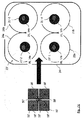
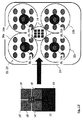
少なくとも一つの第2の光学素子は、少なくとも二つの第2の光学素子を含むことができる。これらの第2の光学素子は、第1の光学素子の光軸から逸れて配置され、特に、第1の光学素子の光軸と各第2の光学素子の光軸との間の距離は等しく、又は、第1の光学素子の(特に、幾何学部分及び/又は反射部分の)中心と、各第2の光学素子の(特に、幾何学部分及び/又は反射部分の)中心との間の距離は等しい。これらの第2の光学素子(特に、その幾何学部分及び/又は反射部分)は、同一面内に配置されることができ、これらの第2の光学素子の(特に、幾何学部分及び/又は反射部分の)中心は、これにより、例えば、正三角形又は正方形等を形成することができる。 The at least one second optical element can include at least two second optical elements. These second optical elements are arranged off the optical axis of the first optical element, and in particular, the distance between the optical axis of the first optical element and the optical axis of each second optical element is equal. Or between the center of the first optical element (especially the geometric part and / or the reflective part) and the center of each second optical element (especially the geometric part and / or the reflective part). The distance is equal. These second optical elements (especially the geometric part and / or the reflective part) can be arranged in the same plane and of these second optical elements (especially the geometric part and / or The center (of the reflective part) can thereby form, for example, an equilateral triangle or a square.
技術的効果及び利点として、第2の光学素子は、第1の光学素子の周りに(特に、回転対称に)配置されることができる。従って、表示装置の射出瞳内で、少なくとも二つの第2の光学素子により形成された少なくとも二つの第2のコリメート光ビームを表す少なくとも二つの第2の光点は、第1の光学素子により形成された第1のコリメート光ビームを表す第1の光点からなる光点パターンの周りに配置される光点パターンを形成することができる。特に、第2の光点は、第2の光点が例えば正三角形又は正方形等を形成するように、中心に置かれた第1の光点の周りに配置されることができる。従って、表示装置の射出瞳内で、少なくも二つの第2の光点は、第1の光点が配置される中心位置の周りに並んだ、使用者の眼球の瞳の少なくとも二つの異なる位置を包含することができる。この少なくとも二つの異なる位置は、使用者の眼球の少なくとも二つの異なる観察方向に対応する。これにより、第2の光学素子の数に相当する数の、使用者の眼球の多くの異なる観察方向について、複数の類似した光点パターンの部分を実現することができる。従って、使用者は、使用者の眼球の異なる観察方向について、表示装置により作り出された像を見ることが可能になる。これにより、大きな視野を有する表示装置が実現可能になる。結果として、この表示装置は改善された設計となる。 As a technical effect and advantage, the second optical element can be arranged around the first optical element, in particular rotationally symmetric. Accordingly, at least two second light spots representing at least two second collimated light beams formed by at least two second optical elements in the exit pupil of the display device are formed by the first optical elements. It is possible to form a light spot pattern arranged around a light spot pattern composed of first light spots representing the first collimated light beam. In particular, the second light spot can be arranged around the first light spot centered such that the second light spot forms eg an equilateral triangle or a square. Therefore, in the exit pupil of the display device, at least two second light spots are arranged around the central position where the first light spot is arranged, at least two different positions of the pupil of the user's eyeball. Can be included. The at least two different positions correspond to at least two different viewing directions of the user's eyeball. Thereby, the part of the several similar light spot pattern is realizable about many different observation directions of the user's eyeball of the number equivalent to the number of 2nd optical elements. Therefore, the user can see images created by the display device for different viewing directions of the user's eyeball. Thereby, a display device having a large visual field can be realized. As a result, this display device has an improved design.
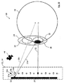
第1の及び第2の光学素子は、共通の(すなわち同一の)発光素子と関連付けることができる。第1の光学素子は、一次偏向、一次回折、及び/又は一次反射によって、関連付けられた共通の発光素子により放射された光から第1のコリメート光ビームを形成するように、関連付けられた共通の発光素子に対して構成及び配置されることができる。上記第1の光学素子の隣りに配置され得る第2の発光素子は、二次偏向、二次回折、及び/又は二次反射によって、関連付けられた共通の発光素子により放射された光から第2のコリメート光ビームを形成するように、関連付けられた共通の発光素子に対して構成及び配置されることができる。言い換えると、第1の光学素子は、表示装置が適切に使用される間、射出瞳の第1の部分(を表す第1の空間部分)に使用者の眼球の瞳が置かれた際の第1の観察方向に沿って眼球が注視する時に、関連付けられた共通の発光素子により放射される光から、使用者の眼球に像を作り出すように構成されることができる。一方で、第2の光学素子は、表示装置が適切に使用される間、射出瞳の第2の部分(を表す第2の空間部分)に使用者の眼球の瞳が置かれた際の第2の観察方向に沿って眼球が注視する時に、関連付けられた共通の発光素子により放射される光から、使用者の眼球に(いわゆる「ゴースト」)像を(「意図的に」)作り出すように構成されることができる。特に、第1の光学素子は、関連付けられた共通の発光素子の近くに配置され、第2の光学素子は、関連付けられた共通の発光素子の遠くに配置されることができる。 The first and second optical elements can be associated with a common (ie, the same) light emitting element. The first optical element may be associated with the associated common light so as to form a first collimated light beam from light emitted by the associated common light emitting element by first order deflection, first order diffraction, and / or first order reflection. The light emitting device can be configured and arranged. A second light emitting element that may be disposed adjacent to the first optical element is a second light emitting element from the light emitted by the associated common light emitting element by second order deflection, second order diffraction, and / or second order reflection. Can be configured and arranged with respect to the associated common light emitting device to form a collimated light beam. In other words, the first optical element is the first optical element when the pupil of the user's eyeball is placed in the first portion (representing the first space portion) of the exit pupil while the display device is properly used. When the eye gazes along one viewing direction, it can be configured to create an image on the user's eye from the light emitted by the associated common light emitting element. On the other hand, the second optical element is the second optical element when the pupil of the user's eyeball is placed in the second portion (representing the second space portion) of the exit pupil while the display device is appropriately used. When the eye gazes along two viewing directions, it creates ("intentionally") an image ("intentionally") in the user's eyeball from the light emitted by the associated common light emitting element Can be configured. In particular, the first optical element can be located near the associated common light emitting element and the second optical element can be located far from the associated common light emitting element.
技術的効果及び利点として、例えば、第1のコリメート光ビームが表示装置の射出瞳の第1の部分を通過し、第2のコリメート光ビームが表示装置の射出瞳の第2の部分を通過するように、第1の及び第2の光学素子並びに共通の発光素子が構成及び配置された場合に、上記共通の発光素子により放射される光を、眼球が表示装置の射出瞳の第1の部分(を表す第1の空間部分)に置かれた時に使用者の眼球の瞳に向けるだけでなく、眼球が表示装置の射出瞳の第2の部分(を表す第2の空間部分)に置かれた時にも使用者の眼球の瞳に向けることができる。従って、第1の光学素子と関連付けられた発光素子により放射される光は、使用者の眼球の異なる観察方向で、使用者の眼球に到達することができる。そのため、この発光素子により放射される光をより効果的に用いることができる。これにより、明るい像を表示する明るい表示装置が実現可能になる。結果として、この表示装置は改善された設計となる。 As a technical effect and advantage, for example, the first collimated light beam passes through a first part of the exit pupil of the display device and the second collimated light beam passes through a second part of the exit pupil of the display device. As described above, when the first and second optical elements and the common light emitting element are configured and arranged, the light emitted from the common light emitting element is used as the first part of the exit pupil of the display device. When placed in (a first space portion representing), the eyeball is placed in a second portion (representing a second space portion) of the exit pupil of the display device as well as being directed toward the pupil of the user's eyeball. Can be directed to the pupil of the user's eyeball. Accordingly, the light emitted by the light emitting element associated with the first optical element can reach the user's eyeball in different viewing directions of the user's eyeball. Therefore, the light emitted from this light emitting element can be used more effectively. As a result, a bright display device that displays a bright image can be realized. As a result, this display device has an improved design.
複数の光学素子の少なくとも一部(特に、第1の及び/又は「中心」光学素子)、及び、関連付けられた発光素子(の全体の少なくとも一部)は、表示装置の少なくとも一つの作動状態において、コリメート光ビームが交差点又は交差領域に方向づけられるような方法で、コリメート光ビームが互いに収束するように構成及び配置されることができる。この交差点又は交差領域は、第1の観察方向から第2の観察方向に変更される時に、使用者の眼球が周りを回転する回転点の近傍に位置するものである。 At least some of the plurality of optical elements (especially the first and / or “center” optical element) and the associated light emitting element (at least part of the whole) are in at least one operating state of the display device. The collimated light beams can be configured and arranged to converge with one another in such a way that the collimated light beams are directed to an intersection or region of intersection. This intersection or intersection region is located in the vicinity of the rotation point where the user's eyeball rotates around when the first observation direction is changed to the second observation direction.
技術的効果及び利点として、表示装置から出たコリメート光ビームの全体の一部は、常に、使用者の眼球の瞳を通過することができる。従って、使用者の眼球の異なる観察方向について、使用者は、表示装置により作り出された像を見ることが可能となる。これにより、大きな視野を有する表示装置が実現可能になる。結果として、この表示装置は改善された設計となる。 As a technical effect and advantage, a part of the entire collimated light beam emerging from the display device can always pass through the pupil of the user's eyeball. Therefore, the user can see the image created by the display device for different viewing directions of the user's eyeball. Thereby, a display device having a large visual field can be realized. As a result, this display device has an improved design.
表示装置は、切り替え可能な偏向装置を具備することができる。この偏向装置は、(特に、偏向装置の切り替えに基づいて)各コリメート光ビームの伝播方向を少なくとも一つの第1の方向と少なくとも一つの第2の方向の間で変更するように構成されることができる。特に、この偏向装置は、複数の異なる群のコリメート光ビームのそれぞれに関して、伝播方向を独立して(すなわち個別に)変更(又は、反射、偏向、若しくは回折)するように構成されることができる。コリメート光ビームの一群は、一つのみのコリメート光ビーム又は二つ以上のコリメート光ビームを含むことができる。 The display device can comprise a switchable deflection device. The deflecting device is configured to change the propagation direction of each collimated light beam between at least one first direction and at least one second direction (especially based on switching of the deflecting device). Can do. In particular, the deflection device can be configured to change (or reflect, deflect, or diffract) the propagation direction independently (ie, individually) for each of a plurality of different groups of collimated light beams. . The group of collimated light beams can include only one collimated light beam or two or more collimated light beams.
技術的効果及び利点として、表示装置から出た任意のコリメート光ビームの伝播方向を、所望の伝播方向に偏向及び/又は反射することができる。例えば、偏向装置は、表示装置から出る全てのコリメート光ビームが使用者の眼球の瞳に入るように構成されることができる。これにより、表示装置の光パワーの全て又はほとんどを、使用者の眼球内に平行化することができる。そのため、発光素子により放射される光をより効果的に用いることができる。このように、使用可能な光の量を増やすことができる。これにより、低パワーで明るい像を表示する、明るくエネルギー効率のよい表示装置が実現可能になる。また、偏向装置は、上述した交差点又は交差領域を再校正するために用いることができる。結果として、この表示装置は改善された設計となる。 As a technical effect and advantage, the propagation direction of any collimated light beam emerging from the display device can be deflected and / or reflected in a desired propagation direction. For example, the deflection device can be configured such that all collimated light beams exiting the display device enter the pupil of the user's eyeball. Thereby, all or most of the optical power of a display apparatus can be collimated in a user's eyeball. Therefore, the light emitted from the light emitting element can be used more effectively. In this way, the amount of usable light can be increased. This makes it possible to realize a bright and energy efficient display device that displays a bright image with low power. The deflection device can also be used to recalibrate the intersection or intersection area described above. As a result, this display device has an improved design.
表示装置、特に、表示装置の偏向装置は、複数の切り替え可能な偏向素子を具備することができる。各偏向素子は、少なくとも一つのコリメート光ビーム、又は複数の異なる群のコリメート光ビームのうちの一つと関連付けることができる。特に、各偏向素子は、一つの各光学素子及び/又は一つの各発光素子と関連付けることができる。偏向素子は、コリメート光ビームが偏向素子を通過した後に表示装置の射出瞳の第1の部分を通過するように、偏向素子がこのコリメート光ビームの伝播方向を固定するオン状態と、コリメート光ビームが偏向素子を通過した後に、上記表示装置の射出瞳の第1の部分と異なる表示装置の射出瞳の第2の部分を通過するように、偏向素子がこのコリメート光ビームの伝播方向を変更(及び/又は回折及び/又は偏向及び/又は反射)するオフ状態の間で切り替え可能とすることができる。これに代わって、偏向素子は、コリメート光ビームが偏向素子を通過した後に表示装置の射出瞳の第1の部分を通過するように、偏向素子がこのコリメート光ビームの伝播方向を固定するオフ状態と、コリメート光ビームが偏向素子を通過した後に、上記表示装置の射出瞳の第1の部分と異なる表示装置の射出瞳の第2の部分を通過するように、偏向素子がこのコリメート光ビームの伝播方向を変更(及び/又は回折及び/又は偏向及び/又は反射)するオン状態の間で切り替え可能であってもよい。 A display device, in particular a deflection device of the display device, can comprise a plurality of switchable deflection elements. Each deflection element can be associated with at least one collimated light beam or one of a plurality of different groups of collimated light beams. In particular, each deflection element can be associated with one optical element and / or one light emitting element. The deflecting element has an ON state in which the deflecting element fixes a propagation direction of the collimated light beam so that the collimated light beam passes through the first portion of the exit pupil of the display device after passing through the deflecting element; After passing through the deflecting element, the deflecting element changes the propagation direction of this collimated light beam so that it passes through a second part of the exit pupil of the display device different from the first part of the exit pupil of the display device. And / or switchable between off-states that are diffracted and / or deflected and / or reflected). Instead, the deflecting element is in an off state in which the deflecting element fixes the propagation direction of the collimated light beam so that it passes through the first part of the exit pupil of the display device after passing through the deflecting element. And after the collimated light beam passes through the deflecting element, the deflecting element passes through the second part of the exit pupil of the display device different from the first part of the exit pupil of the display device. It may be switchable between on states that change the propagation direction (and / or diffraction and / or deflection and / or reflection).
技術的効果及び利点として、使用者の眼球が、表示装置の射出瞳の第1の部分(を表す第1の空間部分)に使用者の眼球の瞳が置かれた際の第1の観察方向から、表示装置の射出瞳の第2の部分(を表す第2の空間部分)に使用者の眼球の瞳が置かれた際の第2の観察方向に変更される時に、偏向装置の対応する切り替えにより、コリメート光ビームを使用者の眼球の異なる観察方向で使用者の眼球の瞳に通過させることができる。従って、表示装置の光パワーの全て又はほとんどを、使用者の眼球内に平行化することができる。そのため、発光素子により放射される光をより効果的に用いることができる。これにより、低パワーで明るい像を表示する、明るくエネルギー効率のよい表示装置が実現可能になる。結果として、この表示装置は改善された設計となる。 As a technical effect and advantage, the first viewing direction when the user's eyeball is placed in the first portion (representing first space portion) of the exit pupil of the display device To the second viewing direction when the pupil of the user's eyeball is placed in the second portion (representing the second space portion) of the exit pupil of the display device. The switching allows the collimated light beam to pass through the pupil of the user's eyeball in different viewing directions of the user's eyeball. Therefore, all or most of the optical power of the display device can be collimated in the user's eyeball. Therefore, the light emitted from the light emitting element can be used more effectively. This makes it possible to realize a bright and energy efficient display device that displays a bright image with low power. As a result, this display device has an improved design.
偏向装置、一つの偏向素子、及び/又は複数の偏向素子(のいくつか又は全て)は、液晶ディスプレイ又は液体レンズ等であってもよく、又は含んでもよい。特に、偏向装置、一つの偏向素子、及び/又は複数の偏向素子(のいくつか又は全て)は、特にはコリメート光ビームの光の偏光(又は偏光状態)に基づき、各コリメート光ビームの伝播方向を少なくとも一つの第1の方向と少なくとも一つの第2の方向の間で変更するように構成されることができる。 The deflection device, one deflection element, and / or multiple deflection elements (some or all) may be or may include a liquid crystal display or a liquid lens. In particular, the deflection device, one deflection element, and / or a plurality (or some) of the deflection elements, in particular based on the polarization (or polarization state) of the light of the collimated light beam, the propagation direction of each collimated light beam Can be configured to change between at least one first direction and at least one second direction.
例えば、偏向装置、一つの偏向素子、及び/又は複数の偏向素子(のいくつか又は全て)は、液晶偏光格子(略:LCPG)であってもよく、又は含んでもよい。このようなLCPGは、例えば、Proc. of SPIE Vol.7093,709302,(2008),doi:10.1117/12.795752、John D. Gonglewski,Richard A. Carreras,Troy A. Rhoadarmer編集、Advanced Wavefront Control: Methods,Devices,and Applications VI、Jihwan Kim, Chulwoo Oh, Michael J. Escuti, Lance Hosting and Steve Serati著、「Wide−angle,nonmechanical beam steering using thin liquid crystal polarization gratings」(以下、Kim et al.と略す)の2.2章「Liquid Crystal Polarization Grating Basics」及び図2に記載されている。 For example, the deflection device, one deflection element, and / or multiple deflection elements (some or all of them) may be or include a liquid crystal polarization grating (abbreviated as LCPG). Such LCPG is described in, for example, Proc. of SPIE Vol. 7093, 709302, (2008), doi: 10.1117 / 12.795752, John D. Gonglewski, Richard A. Carreras, Troy A. et al. Edited by Rhodarmer, Advanced Wavefront Control: Methods, Devices, and Applications VI, Jihwan Kim, Culwoo Oh, Michael J. et al. Escuti, Lance Hosting and Steve Serati, "Wide-angle, non-mechanical beam steering using thin liquid crystallating charts" and "Prithal als. Have been described.
ここで、Kim et al.の開示は引用文献として組み込まれる。本願によって参照されるKim et al.に開示される全ての特徴に関して、保護が請求される。本願によって参照されるKim et al.に開示される全ての特徴は、本発明の技術目的を達成することを助け、またそのため、本願請求項に係る本発明の技術課題の一つ又は全てを解決する方法の一部を成し得る。更に、本願によって参照されるKim et al.に開示される全ての特徴は、本願に含まれる本発明の説明、曳いては出願時の書類の内容に属する。また、本願によって参照されるKim et al.に開示される全ての特徴は、Kim et al.の用語を用いることで正確に定義され、Kim et al.の特定の章を参照して、参照文献Kim et al.に含まれる全ての技術的情報内に認められる。 Here, Kim et al. Is hereby incorporated by reference. Kim et al., Referenced by this application. Protection is claimed for all features disclosed in. Kim et al., Referenced by this application. All the features disclosed in this document help to achieve the technical object of the present invention and can therefore form part of a method for solving one or all of the technical problems of the present invention as claimed. . Furthermore, Kim et al. All the features disclosed in, belong to the description of the invention contained in the present application, that is, the content of the documents as filed. Also, Kim et al. All the features disclosed in Kim et al. Are precisely defined using the terminology of Kim et al. Reference is made to the reference Kim et al. In all technical information contained in
偏向装置、一つの偏向素子、及び/又は複数の偏向素子(のいくつか又は全て)は、Kim et al.の3章「SINGLE LCPG STEERING STAGE」、特にKim et al.の図5(a)に定義されるような、アクティブな(切り替え可能な)偏光格子(略:APG)及び/又は液晶(LC)半波長板であってもよく、又は含んでもよい。
Deflection devices, single deflection elements, and / or multiple deflection elements (some or all of them) are described in Kim et al.
このようなAPG、より一般には、APGを含むLCPGは、Kim et al.の2.3章「Fine Angle Steering Module」に定義されるようなファインアングルステアリングモジュール及び/又はKim et al.の3章「SINGLE LCPG STEERING STAGE」に定義されるようなビームステアリングモジュールとして機能するように構成されることができる。言い換えると、APGは、APGのオフ状態(偏向素子のオフ又はオン状態に相当)において、光を偏向又は回折し(すなわち、Kim et al.の図2(d)及び2(e)のように、APGに入ったコリメート光ビームの伝播方向を変更(又は偏向又は反射し))、APGのオン状態(偏向素子のオン又はオフ状態に相当)において、光を偏向又は回折しない(すなわち、Kim et al.の図2(f)のように、APGに入ったコリメート光ビームの伝播方向を固定する)ように、構成されることができる。また、APGは、APGのオフ状態において、第1の円偏光を有するコリメート光ビームの光を第1の方向に偏向又は回折し、及び/又は、第2の円偏光を有するコリメート光ビームの光を第2の方向に偏向又は回折するように構成されることができる(Kim et al.の図2(d)、2(e)、及び5(a)参照)。第1の及び第2の方向は異なってもよい。APGに入ったコリメート光ビームの光が(まだ)偏光されていない場合、APGは、オフ状態において、第1の円偏光を有するコリメート光ビームの光と第2の円偏光を有するコリメート光ビームの光の両方を偏向又は回折するように構成されることができる(Kim et al.の図5(a)参照)。第1の偏光は、Kim et al.の図5に定義されるような、右回りの円偏光であってもよく、第2の偏光は、Kim et al.の図5に定義されるような、左回りの円偏光であってもよく、逆もまた同様である。
Such APGs, and more generally LCPGs containing APGs, are described in Kim et al. Section 2.3 “Fine Angle Steering Module” of Fine Angle Steering Module and / or Kim et al. Can be configured to function as a beam steering module as defined in
特に、APGは、例えば±0°、±5°、±10°、又は±11°等の離散的な偏向角で、APGに入ったコリメート光ビームの光を偏向するように構成されることができる(Kim et al.の表3参照。「±」は第1の及び第2の円偏光にそれぞれ関する)。離散的な偏向角は、Kim et al.の2.2章「Liquid Crystal Polarization Grating Basics」及びKim et al.の式(3)に定義されるように、任意に設定することができる。 In particular, the APG is configured to deflect the light of the collimated light beam entering the APG with a discrete deflection angle such as ± 0 °, ± 5 °, ± 10 °, or ± 11 °. (See Table 3 of Kim et al. “±” refers to the first and second circular polarizations, respectively). Discrete deflection angles are described in Kim et al. Section 2.2 “Liquid Crystal Polarization Grafting Basics” and Kim et al. It can be set arbitrarily as defined in equation (3).
例えば、偏向装置は、複数のAPGを含むことができる。各APGは、層として、又はKim et al.の4.1章「Simple Coarse Steerer Design」、図6、4.2章「Improved Coarse Steerer Design」、及び図7に定義されるような「ステージ」として配置されることができる。特に、偏向装置は、Kim et al.の4章「COARSE STEERER DESIGN OPTIONS」、図6、及び図7に定義されるような、増大した動作範囲を伴うワイドアングルビームステアリングシステムを実行するために、積層又は段積みされた一組のAPG層又はAPGステージの配列であってもよい。複数のAPGは、それら特有の偏向角が互いに異なっていてもよい。また、複数のAPGは、偏向装置の総偏向角が、Kim et al.の4.1章「Simple Coarse Steerer Design」及び4.2章「Improved Coarse Steerer Design」に定義されるように、異なる離散的な総偏向角の間で切り替え可能であるように配置されることができる。 For example, the deflection device can include a plurality of APGs. Each APG is a layer or as described by Kim et al. 4.1, “Simple Coarse Steerer Design”, FIGS. 6, 4.2, “Improved Coarse Steerer Design”, and “Stage” as defined in FIG. In particular, the deflection device is described in Kim et al. Chapter 4 “COARSE STEERER DESIGN OPTIONS”, a set of APGs stacked or stacked to implement a wide angle beam steering system with an increased range of motion as defined in FIGS. 6 and 7 It may be an arrangement of layers or APG stages. The plurality of APGs may have different specific deflection angles. A plurality of APGs have a total deflection angle of the deflection device of Kim et al. As defined in Section 4.1 “Simple Coarse Steerer Design” and 4.2 “Improved Coarse Steerer Design” to be switchable between different discrete total deflection angles. it can.
技術的効果及び利点として、偏向装置から出たコリメート光ビームの任意の方向を設定することができる。これにより、選択可能な偏向角の範囲が実現可能になる。結果として、この表示装置は改善された設計となる。また、偏向装置及び/又は偏向素子の偏向機能を実現するために、ホログラム及び/又はホログラム光学素子が使用されない。これに関して、本開示の偏向装置は、ホログラム及び/又はホログラム光学素子(特に、これのみ)に頼る偏向装置の代替手段を表すことができる。 As a technical effect and advantage, any direction of the collimated light beam emerging from the deflecting device can be set. This makes it possible to realize a selectable deflection angle range. As a result, this display device has an improved design. Further, no hologram and / or hologram optical element is used to realize the deflection function of the deflection device and / or the deflection element. In this regard, the deflection device of the present disclosure can represent an alternative to a deflection device that relies on holograms and / or hologram optical elements (particularly only).
例えば、偏向装置は、コリメート光ビームの伝播方向に沿って以下に記載される順に配置された、例えば1°の偏向角を有する第1のAPG層1と、例えば5°の偏向角を有する第2のAPG層2と、例えば11°の偏向角を有する第3のAPG層3とを含むことができる。単一のAPG層1、2、及び3のオン/オフ状態に応じて、単一の円偏光に関して、以下の総偏向角を実現することができる(表1)。

偏向装置は、コリメート光ビームの光の偏光を、例えば(特に純粋な)左回りの円偏光又は(特に純粋な)右回りの円偏光に設定する偏光設定装置を含むことができる。このために、偏光設定装置は、半波長板及び/又は四分の一波長板を含んでもよい。偏光設定装置は、偏光設定装置を通過するコリメート光ビームの光の偏光を、(特に純粋な)左回りの円偏光と(特に純粋な)右回りの円偏光との間で、切り替えることができる。このために、偏光設定装置は、一つ以上のポッケルスセルを含んでもよい。制御ユニットは、偏光設定装置を切り替えるように構成されることができる。偏向装置は、複数の偏光設定装置を含むことができる。偏光設定装置は、一つの各光学素子及び/又は一つの各偏向素子と関連付けることができる。特に、偏光設定装置は、コリメート光ビームの伝播方向に沿って、光学素子の(例えばすぐ)下流に、及び/又は、関連付けられた光学素子と関連付けられた偏向素子との間に、配置されることができる。 The deflecting device can include a polarization setting device that sets the polarization of the light of the collimated light beam to, for example, (especially pure) counterclockwise circular polarization or (especially pure) clockwise circular polarization. For this purpose, the polarization setting device may include a half-wave plate and / or a quarter-wave plate. The polarization setting device can switch the polarization of the light of the collimated light beam passing through the polarization setting device between (especially pure) counterclockwise circular polarization and (especially pure) clockwise circular polarization. . For this purpose, the polarization setting device may include one or more Pockels cells. The control unit can be configured to switch the polarization setting device. The deflecting device can include a plurality of polarization setting devices. The polarization setting device can be associated with one optical element and / or one deflection element. In particular, the polarization setting device is arranged along the direction of propagation of the collimated light beam (e.g. immediately downstream) of the optical element and / or between the associated optical element and the associated deflection element. be able to.
技術的効果及び利点として、コリメート光ビームの光の円偏光に応じて、偏向装置から出たコリメート光ビームの偏向方向、すなわち、偏向角の符号(「+」又は「−」のいずれか)を設定することができる。これによって、選択可能な偏向角の範囲を増大することができる。これに加えて、光が使用者の眼球の瞳に入らない方向への偏向によって、光パワー又は光強度が浪費されることがない。結果として、この表示装置は改善された設計となる。 As a technical effect and advantage, depending on the circular polarization of the light of the collimated light beam, the deflection direction of the collimated light beam emitted from the deflecting device, that is, the sign of the deflection angle (either “+” or “−”). Can be set. As a result, the range of selectable deflection angles can be increased. In addition, light power or light intensity is not wasted by deflection in a direction in which light does not enter the pupil of the user's eyeball. As a result, this display device has an improved design.
例えば、偏向装置は、コリメート光ビームの伝播方向に沿って以下に記載される順に配置された、偏光設定装置と、例えば1°の偏向角を有する第1のAPG層1と、例えば5°の偏向角を有する第2のAPG層2と、例えば11°の偏向角を有する第3のAPG層3とを含むことができる。偏光設定装置によって設定されたコリメート光ビームの光の偏光に応じて、また、単一のAPG層1、2、及び3のオン/オフ状態に応じて、以下の総偏向角を実現することができる(表2)。
言い換えると、発光素子により放射された光をそのまま(すなわち、それまで純粋に偏光させないで)用いることができる。この場合、オフ状態の第1のAPG層1を通過した後、二つの偏向方向が生じる。次いで、光ビームは、オフ状態の第1のAPG層1を通過した後、純粋に左回りに円偏光された部分と純粋に右回りに円偏光された部分に分割されることが可能であり、そのため、第2の及び/又は第3のAPG層2、3を通過した際は、ビームの更なる分割は起こらない。
In other words, the light emitted by the light emitting element can be used as it is (that is, without being purely polarized until then). In this case, after passing through the
一方で、発光素子により放射された光は、偏向素子に入る前に、偏光設定装置により純粋に(左又は右周りに)円偏光されるように、偏光させることができる。この場合、(表1に示されるように)一つの偏向方向のみが生じ、光ビームは、第1、第2、及び/又は第3のAPG層1、2、3を通過した際は、分割されない。 On the other hand, the light emitted by the light emitting element can be polarized so as to be purely (left or right) circularly polarized by the polarization setting device before entering the deflecting element. In this case, only one deflection direction occurs (as shown in Table 1) and the light beam splits when it passes through the first, second and / or third APG layers 1, 2, 3 Not.
更に、表示装置は、(上述の)表示装置の像取得装置により生成された位置信号に基づき、偏向装置及び/又は偏向素子を切り替える制御ユニットを具備することができる。特に、制御ユニットは、使用者の眼球の瞳が現行で置かれている表示装置の射出瞳の部分を表示装置から出た(特に全ての)コリメート光ビームが通過するような方法で、コリメート光ビームの伝播方向が偏向装置により変更されるように、像取得装置により生成された位置信号に基づき、偏向装置を切り替えるように構成されることができる。より具体的には、制御ユニットは、使用者の眼球の瞳が表示装置の射出瞳の第1の部分(を表す第1の空間部分)に位置する時に、オン状態又はオフ状態でコリメート光ビームを表示装置の射出瞳の第2の部分に通過させる(であろう)偏向素子のみを、これらの偏向素子から出たコリメート光ビームが表示装置の射出瞳の第1の部分を通過するように、オフ状態あるいはオン状態にそれぞれ設定するように構成されることができる。同様に、制御ユニットは、使用者の眼球の瞳が表示装置の射出瞳の第2の部分(を表す第2の空間部分)に位置する時に、オン状態又はオフ状態でコリメート光ビームを表示装置の射出瞳の第1の部分に通過させる(であろう)偏向素子のみを、これらの偏向素子から出たコリメート光ビームが表示装置の射出瞳の第2の部分を通過するように、オフ状態あるいはオン状態にそれぞれ設定するように構成されることができる。 Furthermore, the display device may comprise a control unit for switching the deflection device and / or the deflection element based on the position signal generated by the image acquisition device of the display device (described above). In particular, the control unit may collimate light in such a way that (especially all) the collimated light beam exiting the display device passes through the exit pupil portion of the display device where the pupil of the user's eyeball is currently placed. It can be configured to switch the deflection device based on the position signal generated by the image acquisition device so that the beam propagation direction is changed by the deflection device. More specifically, when the pupil of the user's eyeball is located in the first part (representing first space part) of the exit pupil of the display device, the control unit is in the on state or in the off state. Are deflected only through the second part of the exit pupil of the display device so that the collimated light beam emanating from these deflecting elements passes through the first part of the exit pupil of the display device. , And can be configured to set to an off state or an on state, respectively. Similarly, the control unit displays the collimated light beam in the on state or in the off state when the pupil of the user's eyeball is positioned in the second portion (representing the second space portion) of the exit pupil of the display device. Only the deflecting elements that will (will be) pass through the first part of the exit pupil of the display device are turned off so that the collimated light beam emanating from these deflecting elements passes through the second part of the exit pupil of the display device Or it can comprise so that it may set to an ON state, respectively.
技術的効果及び利点として、眼球が例えば第1の観察方向から第2の観察方向に変更されることで移動したとしても、偏向素子の対応する切り替えにより、表示装置から出たコリメート光ビームの全て又は少なくともほとんどが使用者の眼球の瞳を通過する。従って、発光素子により放射される光をより効果的に用いることができる。これにより、低パワーで明るい像を表示する、明るくエネルギー効率のよい表示装置が実現可能になる。結果として、この表示装置は改善された設計となる。 As a technical effect and advantage, all of the collimated light beams emitted from the display device can be obtained by corresponding switching of the deflecting elements even if the eyeball is moved, for example, from the first observation direction to the second observation direction. Or at least most passes through the pupil of the user's eyeball. Therefore, the light emitted from the light emitting element can be used more effectively. This makes it possible to realize a bright and energy efficient display device that displays a bright image with low power. As a result, this display device has an improved design.
表示装置は、シースルー部分を有するシースルー部材を具備することができる。シースルー部材は、複数の発光素子を含むことができる。この発光素子は、シースルー部分が、隣接する各対の発光素子の間に光(特に可視光)透過性シースルー領域を有するように、シースルー部分内に相互に間隔をあけて設けることができる。発光素子は、例えば、透明な有機発光素子(OLED)及び/又は透明なトランジスタを用いて発光素子を形成することで、光に対して透明又は実質的に透明であることができる。シースルー部材は、シースルー部分内に設けられた複数の光学素子を更に含むことができる。各発光素子は、関連付けられた光学素子の焦点面に位置することができる。複数の光学素子は、表示装置の平行化光学系を表すことができる。発光素子は、(特に純粋に)左回りの円偏光の光、(特に純粋に)右回りの円偏光の光、及び/又は(任意の方位の)直線偏光の光を放射するように構成されることができる。例えば、発光素子は、レーザー装置として実現されてもよく、又はレーザー装置を含んでもよい。この場合、発光素子から放射される光は既に偏光されている。 The display device can include a see-through member having a see-through portion. The see-through member may include a plurality of light emitting elements. The light-emitting elements can be spaced apart from each other in the see-through portion such that the see-through portion has a light (especially visible light) transmissive see-through region between each pair of adjacent light-emitting elements. The light emitting element can be transparent or substantially transparent to light, for example, by forming the light emitting element using a transparent organic light emitting element (OLED) and / or a transparent transistor. The see-through member may further include a plurality of optical elements provided in the see-through portion. Each light emitting element can be located at the focal plane of the associated optical element. The plurality of optical elements can represent a collimating optical system of the display device. The light emitting element is configured to emit (especially purely) counterclockwise circularly polarized light, (especially purely) clockwise circularly polarized light, and / or linearly polarized light (of any orientation). Can. For example, the light emitting element may be realized as a laser device or may include a laser device. In this case, the light emitted from the light emitting element is already polarized.
技術的効果及び利点として、隣接する各対の発光素子の間にあるシースルー領域により、光がシースルー部材及び/又は(実質的に)透明な発光素子を通過することが可能になる。従って、光が、シースルー領域及び/又は発光素子自体を通って、隣接する各対の発光素子の間を通過することができる。複数の発光素子は表示装置のディスプレイを形成するため、ディスプレイ自体により放射される光と、実体世界からの光の両方が、表示装置を通過することができる。そのため、ディスプレイ、より一般には表示装置は、透明又は少なくとも半透明である。従って、拡張現実映像のために、表示装置を用いる使用者の視界又は視野の線上に表示装置を直接提供することが可能である。結果として、この表示装置は改善された設計となる。 As a technical effect and advantage, a see-through region between each pair of adjacent light-emitting elements allows light to pass through the see-through member and / or a (substantially) transparent light-emitting element. Accordingly, light can pass between each pair of adjacent light emitting elements through the see-through region and / or the light emitting element itself. Since the plurality of light emitting elements form the display of the display device, both light emitted by the display itself and light from the real world can pass through the display device. Thus, the display, more generally the display device, is transparent or at least translucent. It is therefore possible to provide a display device directly on the line of sight or field of view of the user using the display device for augmented reality video. As a result, this display device has an improved design.
本明細書を通して、複数の構成要素(例えば、光学素子及び/又は発光素子等)のうちのある構成要素の特質を明らかにする特徴を参照するときに、その複数の要素の一つ、少なくとも一つ、又は各々は、対応する特徴によって明らかにされてもよい。 Throughout this specification, when referring to features that characterize a component of a plurality of components (eg, optical elements and / or light emitting elements, etc.), at least one of the plurality of elements is referred to. One or each may be manifested by a corresponding feature.
本発明の更なる特徴、利点、及び技術効果が、添付の図を参照して、以下の例示的な実施態様の説明から明らかになる。 Further features, advantages and technical advantages of the present invention will become apparent from the following description of exemplary embodiments with reference to the accompanying drawings.
図1、5、7〜13a、及び14aに表示装置10が示される。表示装置10は、シースルー部分14を有するシースルー部材12を具備する。シースルー部材12は、例えば、ビューイングポート、乗り物のフロントガラス又は窓、ヘルメットのバイザー、ガラス、眼鏡の接眼レンズ、矯正レンズ、眼鏡レンズ等を表す。
A
シースルー部材12は、発光素子16のアレイを含む。例示的に、発光素子16のいくつかのみが示され、小さな長方形及び/又は小さな円/楕円として概略的に表される。更なる発光素子16は、点で表される(図1、5、7〜13a、及び14a参照)。発光素子16のアレイは、シースルー部分14が、隣接する(いくつか又は全ての)対の発光素子16の間に可視光透過性シースルー領域15を有するように、シースルー部分14内に相互に間隔をあけて、重ならない方法で、設けることができる(例として図1参照)。各発光素子16は、可視光17を放射する。
The see-through member 12 includes an array of
表示装置10は、細長い長方形(例えば、図1参照)や曲線(図11参照)として概略的に示される複数の光学素子18も具備する。光学素子18は、発光素子16のアレイから光17を受ける。特に、各光学素子18は、少なくとも一つの各発光素子16と関連付けられ、関連付けられた発光素子16により放射された光17から少なくとも一つのコリメート光ビーム20を形成する(特に図1参照)。図において、単一のコリメート光ビーム20は、単一の長い矢印(図1、5、7〜13a、及び14a参照)及び/又は二つ以上の平行な長い矢印17’、17”(図2a、3a、及び12)により概略的に表される。各発光素子16は、関連付けられた光学素子18の焦点面19に位置する(特に図2a、3a、12、13b、13d、14a、及び15a〜15c比較参照)。これに関して、複数の光学素子18は、表示装置10の平行化光学系を表す。更なる光学素子18も点で表される(図1、5、7〜13a、及び14a参照)。
The
表示装置10は、表示装置10から出たコリメート光ビーム20により、使用者が彼/彼女の視界を(ほぼ)無限遠に調節することを可能にする。例えば、表示装置10の像は、使用者の眼球30の瞳28の方向に表示装置10から出るコリメート光ビーム20によって表すことが可能であり(図5、7〜11、及び13a参照)、無限遠に調節された人間の水晶体によって網膜上に焦点が合わせられる。この点で、表示装置10によって放射されるコリメート光ビーム20は、無限遠の(又は少なくとも、ほぼ無限遠の)距離に像を作り出すことができる。
The
更に、対の発光素子16の間にあるシースルー領域15によって、光が、シースルー領域15を通って、隣接する対の発光素子16の間を通過することができる。そのため、表示装置10自体により放射される光17と、実体世界からの光9の両方(例として図11参照)が、表示装置10を通過することができる。それゆえ、ディスプレイ、より一般には表示装置10は、透明又は少なくとも半透明である。従って、拡張現実映像のために、表示装置10を用いる使用者の視界又は視野の線上に表示装置10を直接提供することが可能である。
Further, the see-through
一般に、光学素子18は、可視光スペクトルの、あるスペクトル部分のみを包含する偏向スペクトル内でだけ可視光を反射/偏向/屈折/回折し、偏向スペクトルと透過スペクトルは重複せず(すなわち、これらのスペクトルは分離されている)、可視光スペクトルの別のスペクトル部分のみを包含する透過スペクトル内の可視光に対しては透明である。従って、(図11に例示されるように)実体世界から来た光9等の透過スペクトル内の可視光は、反射、偏向、屈折、及び/又は回折されずに光学素子18を通過し、一方で、関連付けられた発光素子16により放射された光17は、関連付けられた光学素子18により反射、偏向、屈折、及び/又は回折され、コリメート光ビーム20を形成する。
In general,
更に、光学素子18の偏向スペクトルは、その関連付けられた少なくとも一つの発光素子16の放射スペクトルを完全に包含する。しかしながら、光学素子18の偏向スペクトルは、光学素子18と関連付けられていない発光素子16の放射スペクトルを包含しない。言い換えると、光学素子18は、関連付けられていない発光素子16により放射される光に対して透明である。
Furthermore, the deflection spectrum of the
従って、光学素子18の偏向スペクトルと発光素子16の放射スペクトルを構成することで、光学素子18と発光素子を互いに「関連付ける」ことができる。
Therefore, by constructing the deflection spectrum of the
例えば、図12に示されるように、各光学素子18は、表示装置10の出現性のホログラフィック感光乳剤領域(同様に符号18で表される)に記録された各々のホログラム光学素子(HOE)であってもよい。出現性のホログラフィック感光乳剤領域18は、特定の幾何学部分25を有する。各光学素子18は、ホログラム凹面鏡(すなわち、凹面鏡の反射型ホログラム)を表すことができる。これに代わって、図11に示されるように、各光学素子18は、二色性であり、球状又は放射状の反射部分25を有する反射膜(同様に符号18で表される)であってもよい。反射膜18は、透明な基材等の透明又は少なくとも半透明の物体46の表面に(例えば、蒸着、スパッタリング等で)塗布された被膜である。各光学素子18は、回折格子、透過型振幅格子、透過型位相格子、反射型位相格子、及び/又は反射型振幅格子、及び/又は液晶偏光格子及び/又は液体レンズ(不図示)であってもよい。
For example, as shown in FIG. 12, each
光学素子18の上記の実現例のいずれの場合も、光学素子18は、焦点距離fL、焦点面19、幾何学部分又は偏向/反射/屈折部分25、「最小収差位置」60、光軸50、参照軸62、及び物体軸64によって特徴付けられる。これらの用語は、図15a〜15cで説明及び定義される。
In any of the above implementations of
特に図15bに示されるように、最小収差位置60は、点状の発光素子16がこの最小収差位置60に位置し、光学素子18がこの点状の発光素子16から光17を受け、該受けられた光17からコリメート光ビーム17’、17”、20を形成する時に、光学収差が最小となる位置である。例えば、図15aに示されるように、光学素子18の最小収差位置60は、意図された光学素子18の位置及び/又は方位に対して(より具体的には、光学素子18が形成される感光乳剤領域18の位置及び/又は方位に対して)光学素子18をホログラム光学素子18として記録する間、記録される物体66が存在する、物体66の中心の位置60である。これに関して、最小収差位置は、光学素子18の焦点面19の中心として定義又は理解することができる。
In particular, as shown in FIG. 15b, the
光学素子18の焦点距離fLは、光学素子18の最小収差位置60と、光学素子18の幾何学部分25及び/又は反射部分25が配置される面68の間の最短距離と定義又は理解することができる(図15a〜15c参照)。
The focal length fL of the
光学素子18の参照軸62は、光学素子18の幾何学部分25及び/又は反射部分25の中心70を通り、かつ、光学素子18の最小収差位置60に位置する点状の発光素子16から受けられた光17から光学素子18により形成されたコリメート光ビーム20と平行な直線として定義又は理解することができる(図15b参照)。参照軸62の方位は、例えば、光学素子18をホログラム光学素子として記録する間、ホログラム光学素子18が記録される感光乳剤領域18に対して参照ビーム72を配置する及び/又は傾けることによって、調整及び固定されることができる(図15a参照)。参照ビーム72は、ホログラム記録プロセス中、記録された物体66から散乱される波74(いわゆる物体ビーム74)と共に、感光乳剤領域18にホログラムの干渉パターンを形成する光参照波(図15aでは8つの平行な直線として示される)の光線の束の中心光線(同様に符号62で示される)によって表すことができる(再び図15a参照)。
The
光学素子18の物体軸64は、最小収差位置60を通り、光学素子18の幾何学部分25及び/又は反射部分25が配置される面68と垂直な直線として定義又は理解することができる(図15a〜15c参照)。
The
光学素子18の光軸50は、光学素子18の幾何学部分25及び/又は反射部分25の中心70を通り、かつ、光学素子18の最小収差位置60を通る直線として定義又は理解することができる(図15a〜15c参照)。これに関して、光学素子18の光軸50は、上記中心70を位置決めし、上記最小収差位置60を位置決めすることによって、調整及び固定されることができる。光軸50の方位は、例えば、光学素子18をホログラム光学素子18として記録する間、ホログラム光学素子18が記録される感光乳剤領域18に対して、ホログラムとして結像される物体66(すなわちレンズ又は鏡等)を配置することによって、調整及び固定されることができる(図15b参照)。特に、光軸50は、物体軸64と平行でもよく、又は一致すらしてもよい(例えば、図2a参照)。しかしながら一般に、光軸50は、必ずしも物体軸64と一致する必要はなく、及び/又は、必ずしも平行である必要はなく、物体軸64に対して傾いていてもよい(例えば、図15a〜15c参照)。参照軸62についても同様のことが言える。光軸50は、参照軸62と平行でもよく、又は一致すらしてもよい(例えば、図2a参照)。しかしながら一般に、必ずしも光軸50は、参照軸62と一致する必要はなく、及び/又は、必ずしも平行である必要はなく、参照軸62に対して傾いていてもよい(例えば、図15a〜15c参照)。発光素子16が焦点面19内かつ関連付けられた光学素子18の光軸50上に位置する場合、光学素子18は、関連付けられた発光素子16により放射される光17からコリメート光ビーム17’、17”、20を形成し、このコリメート光ビーム17’、17”、20は、参照軸62と平行に、参照軸62に沿って、発光素子18から出る(例えば、図15b参照)。しかしながら、発光素子16が焦点面19内に位置するが、関連付けられた光学素子18の光軸50から逸れている場合、光学素子18は、関連付けられた発光素子16により放射される光17からなおもコリメート光ビーム17’、17”、20を形成するが、このコリメート光ビーム17’、17”、20は、参照軸62に対して偏向した(すなわち、傾いた、角度を有する)方法で、光学素子18から出る(例えば、図15c参照)。
The
上記を考慮すれば、それぞれ所望の方位を伴う参照軸62、物体軸64、及び/又は光軸50を有する光学素子18を実現することも可能である。また、光学素子18及び関連付けられた発光素子16は、(以下でより詳細に説明されるように)関連付けられた発光素子16から受けられた光17から光学素子18により形成されたコリメート光ビーム20が表示装置10の射出瞳24の所望の部分22、26、54を通過するように、(互いに対して)構成及び配置されることもできる。言い換えると、関連付けられた発光素子16を光学素子18、特には光学素子18の焦点面19内の光軸50に対して配置することにより、コリメート光ビーム20の任意の方向を設定することができる。これらの可能性は、光学素子18及び発光素子16の特定の構成及び配置から生じる特定の機能的特徴を得るために用いられる。詳細には以下の通りである。
In view of the above, it is also possible to realize an
図2aは、3つの例示的な光線17がどのように一つの発光素子16により放射され、この一つの発光素子16と関連付けられた一つの光学素子18により受けられるかを示している。光学素子18が、関連付けられた発光素子16により放射された光線17から一つのコリメート光ビーム20をどのように形成するかが詳細に示される。これは、光線17が、光学素子18により偏向/反射/回折された後、(実質的に)平行な光線17’、17”として光学素子18から出るためである。関連付けられた発光素子16から受けられた光17を平行化するため、光学素子は、焦点面19と所定の焦点距離fLを有し、関連付けられた発光素子16は、関連付けられた光学素子18の焦点面19内に配置される。より具体的には、発光素子16は、光軸50上かつ焦点面19内に(またそのため、最小収差位置60に)位置する。従って、コリメート光ビーム20は、参照軸62に沿って光学素子18から出る。
FIG. 2 a shows how three
関連付けられた発光素子16から受けられた光17から光学素子18により形成されたコリメート光ビーム20は、とりわけ、平行な光線17’、17”を含むため、コリメート光ビーム20を表すには、全ての平行な光線17’、17”の束の中心光線17”のみを用いれば十分である(図2a参照)。従って、光学素子18は、関連付けられた発光素子16の(虚)像が無限遠(すなわち無限距離)に提供されるような、拡大光学特性を有していると言える。
The collimated
図2aは、コリメート光ビームが例えばスクリーンや角膜等の使用者の眼球の表面に当たった時に、コリメート光ビーム20により生成される光点21も示している。このように、関連付けられた発光素子16により放射される光17は、光学素子18とその関連付けられた発光素子16により生成される光点21を含む光点パターン23に「投影」されると言える。
FIG. 2a also shows a
図2bは、光学素子18及び関連付けられた発光素子16をより抽象的な略図、いわゆる「投影図」で示している。特に、図2bは、関連付けられた発光素子16と共に、光学素子18の幾何学及び偏向/反射/屈折部分25も正面図で示している。この例において、この部分25は長方形及びほぼ正方形状である。そのため、発光素子16が点状であると考えた場合、光点21もまた長方形及びほぼ正方形状になり得る。図2b(また、図3b、4、6、13c、13e〜13h、及び14b)の大きな矢印は、関連付けられた発光素子16により放射された光17が対応する光点パターン23に投影されたことを示す。
FIG. 2 b shows the
図3aの例では、一つの光学素子18が3つの発光素子16a、16b、16cに関連付けられており、そのため、光学素子18は3つのコリメート光ビーム20a、20c(図3aでは明確性のため、3つのうち2つのコリメート光ビーム20a、20cのみが示されている)を提供する。また明確性のために、発光素子16a由来であり、光学素子18により偏向/反射/回折された後、平行に光学素子18から出た光線17a’、17a”(実線)、及び、発光素子16c由来であり、光学素子18により偏向/反射/回折された後、同様に平行に光学素子18から出た光線17c’、17c”(破線)のみが示される。図2aと同様に、中心光線17a”はコリメート光ビーム20aを表し、中心光線17c”はコリメート光ビーム20cを表す。図3aに見られるように、関連付けられた発光素子16により放射された光は、十分に遠い距離で、3つの重ならない光点21a、21b、21cを含む光点パターン23に投影される。各光点21a〜cは、3つのコリメート光ビーム20a、20cのうちの一つにより生成される。
In the example of FIG. 3a, one
図3bは、図3aの光学素子18及び関連付けられた3つの発光素子16a、16b、16cをより抽象的な略図で示している。特に、図3bは、関連付けられた3つの発光素子16a〜cと共に、光学素子18の幾何学及び偏向/反射/屈折部分25を正面図で示している。この例において、この部分25は長方形及びほぼ正方形状である。そのため、発光素子16a〜cの各々が点状であると考えた場合、各光点21a〜cもまた長方形及びほぼ正方形状になり得る。図4の大きな矢印は、関連付けられた一つの各発光素子16a〜cにより放射された光17から光学素子18により形成された各コリメート光ビームが、対応する光点21a〜cに投影されたことを示す。複数の光点21a〜cは、光点パターン23を形成する。
FIG. 3b shows in more abstract schematic form the
図4は、9つの発光素子16a〜iに関連付けられた一つの光学素子18を示す。特に、図4は、関連付けられた9つの発光素子16a〜iと共に、光学素子18の幾何学及び偏向/反射/屈折部分25を正面図で示している。この例において、この部分25は長方形及びほぼ正方形状である。そのため、発光素子16の各々が点状であると考えた場合、各光点21a〜iもまた長方形及びほぼ正方形状になり得る。図4の大きな矢印は、関連付けられた一つの各発光素子16a〜iにより放射された光から光学素子18により形成された各コリメート光ビームが、対応する光点21a〜iに投影されたことを示す。この光点は、光点パターン23を形成する。
FIG. 4 shows one
各発光素子16は、発光素子16が可視光17を放射するオン状態(図において灰色の色調で示される)と、発光素子16が可視光17を放射しないオフ状態(図において白の色調で示される)の間で切り替え可能である。
Each
各発光素子16は、単一のOLEDであってもよく、表示装置10のディスプレイの一つのピクセル、又は(特に多色ピクセル27を表す)表示セグメント27の一つの(特に単色の)ピクセルを形成する。これは、複数の発光素子16(すなわちピクセル)が、単一の表示セグメント27に組み合わされることを意味する(特に、図3a〜7比較参照)。これにより、いくつかの発光素子をオフに切り替え、いくつかの発光素子をオンに切り替えることで、単一の表示セグメント27上に(図4の「X」等の)情報を表示することが可能になる。
Each
発光素子16及び光学素子18の上述の特性は、とりわけ、表示装置10の視野を増大するために用いられる。詳細には以下の通りである。
The above-mentioned characteristics of the
図5は、(少なくとも)6つの光学素子18−1〜18−6を有する表示装置10を側面図で示している。各光学素子18−1〜18−6は、9つの発光素子16a〜16i(図4参照)を有する一つの各表示セグメント27(同様に図4参照)に関連付けられているが、明確性のために各表示セグメント27の中心発光素子16eのみが符号16−1〜16−6で与えられている。
FIG. 5 shows a side view of a
図5に例示されるように、複数の光学素子18−1〜18−6及び発光素子16−1〜16−6のアレイは、コリメート光ビーム20−1〜20−6の少なくとも一つの第1の一部分20−3〜20−5が表示装置10の射出瞳24の少なくとも一つの第1の部分22を通過し、上記コリメート光ビーム20−1〜20−6の第1の一部分20−3〜20−5と異なる、コリメート光ビーム20−1〜20−6の少なくとも一つの第2の一部分20−1が、表示装置10の射出瞳24の少なくとも一つの第2の部分26を通過するように、構成及び配置される。ここで、第2の部分26は、第1の部分22とは異なる(またこの例では、空間的に分断さえされた)ものである。
As illustrated in FIG. 5, the array of the plurality of optical elements 18-1 to 18-6 and the light emitting elements 16-1 to 16-6 includes at least one first of the collimated light beams 20-1 to 20-6. Portion 20-3 to 20-5 pass through at least one
これは、対応する「投影図」において(図6参照)、複数の光学素子18−1〜18−6及び発光素子16−1〜16−6のアレイが、コリメート光ビーム20−1〜20−6が光点21−1〜21−6に投影されるように、構成及び配置されることを意味する。各光点21−1〜21−6は、一つの各コリメート光ビーム20−1〜20−6により表される。光点21−1〜21−6は、光点パターン23−1〜23−6に属し、各光点21−1〜21−6は、一つの光学素子18−1〜18−6及びその関連付けられた発光素子16−1〜16−6により生成される。例えば、光点21−1は、光点パターン23−1に属し、光点パターン23−1は、光学素子18−1及びその関連付けられた発光素子16−1によって生成される。言い換えると、光点パターン23−1は、光学素子18−1及びその関連付けられた表示セグメント27によって生成される。
This is because, in the corresponding “projection view” (see FIG. 6), an array of a plurality of optical elements 18-1 to 18-6 and light emitting elements 16-1 to 16-6 is formed into collimated light beams 20-1 to 20-. 6 is projected and projected onto the light spots 21-1 to 21-6. Each light spot 21-1 to 21-6 is represented by one collimated light beam 20-1 to 20-6. The light spots 21-1 to 21-6 belong to the light spot patterns 23-1 to 23-6, and each of the light spots 21-1 to 21-6 includes one optical element 18-1 to 18-6 and its association. The light emitting elements 16-1 to 16-6 are produced. For example, the light spot 21-1 belongs to the light spot pattern 23-1, and the light spot pattern 23-1 is generated by the optical element 18-1 and its associated light emitting element 16-1. In other words, the light spot pattern 23-1 is generated by the optical element 18-1 and its associated
図5及び6に更に例示されるように、射出瞳24の第1の部分22は、表示装置10が適切に使用される間、使用者の眼球30が少なくとも一つの第1の観察方向32に沿って表示装置10の中心を注視する時に、この眼球30の瞳28が置かれる第1の空間部分(同様に符号22で示される)を表す。射出瞳24の第2の部分26は、表示装置10が適切に使用される間、使用者の眼球30が第1の観察方向32とは異なる方位の少なくとも一つの第2の観察方向34に沿って表示装置10の周辺を注視する時に、この眼球30の瞳28が置かれる、第1の空間部分22と空間的に異なる第2の空間部分(同様に符号26で示される)を表す(例として、図5の一点鎖線32、34比較参照)。
As further illustrated in FIGS. 5 and 6, the
図6に示されるように、光点21−1〜21−6は、表示装置10の射出瞳24内で、重ならない方法で、互いに対して空間的に分離されている。従って、表示装置10の射出瞳24内で、光点21−1〜21−6は、使用者の眼球30の異なる観察方向32、34に対応する、使用者の眼球30の瞳28の異なる位置を包含することができる(図6に、使用者の眼球30の瞳の2つの例示的な位置が示される)。そのため、使用者は、使用者の眼球30の異なる観察方向32、34について、表示装置10により作り出された像を見ることが可能になる。これにより、大きな視野を有する表示装置10が実現可能になる。
As shown in FIG. 6, the light spots 21-1 to 21-6 are spatially separated from each other in a non-overlapping manner within the
図7に示される例において、光学素子18−1〜18−6及び発光素子16−1〜16−6は、コリメート光ビーム20−1〜20−6が交差領域36に方向づけられるような方法で、表示装置10から出たコリメート光ビーム20−1〜20−6が収束するように構成及び配置される。この交差領域は、表示装置10が適切に使用される間、第1の観察方向32から第2の観察方向34に変更される時に、使用者の眼球30が周りを回転する回転点38の近傍に位置する。より一般的に言うと、複数の光学素子18−1〜18−6の少なくとも一部、及び、関連付けられた発光素子16−1〜16−6の少なくとも一部は、表示装置10の少なくとも一つの作動状態において、コリメート光ビーム20−1〜20−6が交差領域36に方向づけられるような方法で、コリメート光ビーム20−1〜20−6が互いに収束するように構成及び配置される。
In the example shown in FIG. 7, the optical elements 18-1 to 18-6 and the light emitting elements 16-1 to 16-6 are such that the collimated light beams 20-1 to 20-6 are directed to the
これにより、コリメート光ビーム20−1〜20−6のうち一つ以上(20−3〜20−5)が、第1の観察方向32で、使用者の眼球30の瞳28を通過し、コリメート光ビーム20−1〜20−6のうち一つ以上(20−1)が、第2の観察方向34で、使用者の眼球30の瞳28を通過する(図7参照)。そのため、使用者は、使用者の眼球30の異なる観察方向32、34について、より具体的には使用者の眼球30の異なる回転状態について、表示装置10により作り出された像を見ることが可能になる。
Thereby, one or more (20-3 to 20-5) of the collimated light beams 20-1 to 20-6 pass through the
表示装置10の適切な使用を確実にするために、表示装置10は、使用者の眼球30に対して表示装置10を配置する及び/又はしっかり保持するガラスフレームや眼鏡フレーム等の位置決め装置(不図示)を具備することができる。より具体的には、位置決め装置を用いることで、予め決められた方法で、表示装置10の位置及び方位に対する使用者の顔又は頭の位置及び方位を定めることができる。位置決め装置は、表示装置10の射出瞳24(を表す空間部分24)内に使用者の眼球30の瞳28を配置するように構成されることができる。
In order to ensure proper use of the
図8a〜8dの例に示されるように、表示装置10は、切り替え可能な偏向装置40を具備する。偏向装置40は、切り替えられると、各コリメート光ビーム20の伝播方向を少なくとも一つの第1の方向と少なくとも一つの第2の方向の間で変更できる。特に、偏向装置40は、複数の異なる群のコリメート光ビーム20のそれぞれに関して、伝播方向を独立して(すなわち個別に)変更することができる。コリメート光ビーム20の一群は、一つのコリメート光ビーム20又は二つ以上のコリメート光ビーム20を含むことができる。
As shown in the examples of FIGS. 8 a to 8 d, the
より具体的には、偏向装置40は、図8a〜8dで灰色及び/又は黒色の細長い長方形として示される、複数の切り替え可能な偏向素子42を含む。各偏向素子42は、一つのコリメート光ビーム20(例えば20a及び42a参照)と関連付けられ、偏向素子42から出たコリメート光ビーム20が、射出瞳24の、ある部分(例えば、図8bの第1の部分22等)を通過するように、偏向素子42がその偏向素子42に入ったコリメート光ビーム20の伝播方向を固定するオン状態(図8a〜8dにおいて灰色の細長い長方形として示される)と、偏向素子42から出たコリメート光ビーム20が、射出瞳24の別の部分(例えば、図8cの第2の部分26等)を通過するように、偏向素子42がその偏向素子42に入ったコリメート光ビーム20の伝播方向を変更するオフ状態(図8a〜8dにおいて黒色の細長い長方形として示される)の間で切り替え可能である。
More specifically, the
更に、表示装置10は、使用者の眼球30の瞳28の像を取得し、使用者の眼球30の瞳28の位置を表す位置信号を生成する像取得装置(又はアイトラッカー)44を具備する。これにより、使用者の眼球30の瞳28の位置を追跡することが可能になる(特に図8a〜8d参照)。
Furthermore, the
表示装置10は、位置信号に基づき、偏向装置40及び偏向素子42を切り替える制御ユニット(不図示)も具備する。このために、制御ユニットは、使用者の眼球30の瞳28が現行で置かれている射出瞳24の部分22又は26を、表示装置10から出た全てのコリメート光ビーム20が通過するような方法で、コリメート光ビーム20の伝播方向が偏向装置40により変更されるように、像取得装置44により生成された位置信号に基づき、偏向装置40を制御する(図8b及び8c参照)。より具体的には、制御ユニットは、(図8a及び8bに示されるように)使用者の眼球30の瞳28が射出瞳24の第1の部分22に位置する時に、(「灰色の」)オン状態でコリメート光ビーム20aを射出瞳24の第2の部分26に通過させる偏向素子42a(図8a参照)のみを、これらの偏向素子42aから出たコリメート光ビーム20aが射出瞳24の第1の部分22を通過するように、(「黒色の」)オフ状態に設定する(図8b参照)。同様に、制御ユニットは、(図8cに示されるように)使用者の眼球30の瞳28が射出瞳の第2の部分26に位置する時に、(「灰色の」)オン状態でコリメート光ビーム20bを射出瞳24の第1の部分22に通過させる偏向素子42b(図8b参照)のみを、これらの偏向素子42bから出たコリメート光ビーム20bが射出瞳24の第2の部分26を通過するように、(「黒色の」)オフ状態に設定する(図8c参照)。
The
これにより、使用者の眼球30が、射出瞳24の第1の部分22に使用者の眼球30の瞳28が置かれた際の第1の観察方向32(図8a及び8b参照)から、射出瞳24の第2の部分26に使用者の眼球30の瞳28が置かれた際の第2の観察方向34(8c参照)に変更された時に、偏向装置40及び偏向素子42の対応する切り替えにより、コリメート光ビーム20、20a、20bを、使用者の眼球30の異なる観察方向32、34で使用者の眼球30の瞳28に通過させることができる(図8b及び8c参照)。従って、表示装置10の全光パワーを、使用者の眼球30内に平行化することができる。
As a result, the user's
特に、偏向装置40又は各偏向素子42は、コリメート光ビーム20の光の偏光状態にも基づいて、コリメート光ビーム20の伝播方向を変更することができる。このために、偏向装置40は、液晶偏光格子(略:LCPG)を含む。より具体的には、各偏向素子42は、アクティブな切り替え可能な偏光格子(略:APG)及び液晶(LC)半波長板(不図示)を含む。APGのオフ状態(すなわち、偏向素子42のオフ状態)では、APGは光を偏向又は回折する(すなわち、APGに入ったコリメート光ビーム20の伝播方向を変更又は偏向する)。APGのオン状態(すなわち、偏向素子42のオン状態)では、APGは光を偏向又は回折しない(すなわち、APGに入ったコリメート光ビーム20の伝播方向を固定する)。偏向装置40は、コリメート光ビーム20の光の偏光を、純粋な左回りの円偏光又は純粋な右回りの円偏光のいずれかに設定する偏光設定装置45を含むことができる。より具体的には、(図8a〜8dで薄灰色及び/又は黒色の細長い長方形として示される)一つの偏光設定装置45は、一つの各光学素子18及び一つの各偏向素子16と関連付けられる。この偏光設定装置45は、コリメート光ビーム20の伝播方向に沿って、関連付けられた光学素子18のすぐ下流に、関連付けられた光学素子18と関連付けられた偏向素子42との間に配置される。
In particular, the deflecting
偏光設定装置45は、コリメート光ビーム20の光の偏光を(図8a〜8dで薄灰色の細長い長方形として示される)純粋な左回りの円偏光と、(図8cで黒色の細長い長方形として示される)純粋な右回りの円偏光との間で切り替える制御ユニットにより、切り替え可能である。このために、偏光設定装置は、一つ以上のポッケルスセル、半波長板、及び/又は四分の一波長板(不図示)の組み合わせを含む。
The
これにより、コリメート光ビーム20の光の円偏光に応じて、偏向装置40から出たコリメート光ビーム20の偏向方向、すなわち、偏向角の符号(「+」又は「−」のいずれか)を設定することができる。例えば、コリメート光ビーム20が(図8a〜8dで薄灰色の細長い長方形として示される)純粋な左回りの円偏光に設定されるように偏光設定装置45が切り替えられた場合、偏向装置40、特に偏向素子42から出たコリメート光ビーム20の偏向方向は、例えば下方に偏向され(図8b及び図8d参照)、コリメート光ビーム20が(図8cで黒色の細長い長方形として示される)純粋な右回りの円偏光に設定されるように偏光設定装置45が切り替えられた場合、偏向装置40、特に偏向素子42から出たコリメート光ビーム20の偏向方向は、例えば上方に偏向される(図8c参照)。言い換えると、発光素子42により放射された光を、この光が偏向素子42に入る前に、偏光設定装置45により純粋な(左又は右回りの)円偏光に偏向させることができる。その場合、二つではなく、一つの偏向方向のみが生じる(図8a〜8d参照)。
Accordingly, the direction of deflection of the collimated
図9の例に示されるように、第1の光学素子18a及び第2の光学素子18bは、少なくとも一つの共通の発光素子16と関連付けられ、第1の光学素子16aは、一次偏向、一次回折、及び/又は一次反射によって、共通の発光素子16により放射された光17から、射出瞳24の第2の部分26を通過する第1のコリメート光ビーム20aを形成するように、共通の発光素子16に対して構成及び配置され、一方で、第1の光学素子18aのすぐ隣りに(すなわち隣接して)配置された第2の発光素子18bは、二次偏向、二次回折、及び/又は二次反射によって、共通の発光素子16により放射された光17から、射出瞳24の第1の部分22を通過する第2のコリメート光ビーム20bを形成するように、共通の発光素子16に対して構成及び配置される。すなわち、第1の光学素子18aは、表示装置10が適切に使用される間、射出瞳24の第1の部分22に使用者の眼球30の瞳28が置かれた際の第1の観察方向32に沿って眼球30が注視する時に、発光素子16により放射される光17から、使用者の眼球30に像を作り出し(図9参照)、一方で、第2の光学素子18bは、表示装置10が適切に使用される間、射出瞳24の第2の部分26に使用者の眼球30の瞳28が置かれた際の第2の観察方向34に沿って眼球30が注視する時に、発光素子16により放射される光17から、使用者の眼球30に(いわゆる「ゴースト」)像を(「意図的に」)作り出す(図7及び9比較参照)。第1の光学素子18aは、関連付けられた共通の発光素子16の近くに配置され、第2の光学素子18bは、関連付けられた共通の発光素子16の遠くに配置される。特に、関連付けられた共通の発光素子16は、第1の光学素子18aの光軸50a上、特に、第1の光学素子18aの最小収差位置60aに配置されることができ、一方で、関連付けられた共通の発光素子16は、第2の光学素子18bの光軸50bから逸れて、またそのため第2の光学素子18bの最小収差位置60bから逸れて配置されることができ、これにより、一次偏向/回折/反射によって生じた光学収差と比べて深刻な光学収差を伴う二次偏向/回折/反射を起こすことができる。第1の及び第2の光学素子18a、18bの光軸50a、50bは、互いに対して平行にずらされる(すなわち一致しない)。
As shown in the example of FIG. 9, the first
これにより、共通の発光素子16により放射される光17は、眼球30が射出瞳24の第1の部分22に置かれた時に、使用者の眼球30の瞳28に向けられるだけでなく、眼球30が射出瞳24の第2の部分26に置かれた時にも、使用者の眼球30の瞳28に向けられる。従って、第1の及び第2の光学素子18a、18bの両方と関連付けられた共通の発光素子16により放射される光17は、使用者の眼球30の異なる観察方向32、34で、使用者の眼球30に到達することができる。
Thereby, the light 17 emitted by the common
図10の例に示されるように、光学素子18は、重ならない方法で互いに対して空間的に分離されて配置された、(小さい円として概略的に示される)少なくとも一つの第1の発光素子16a及び(小さい長方形として概略的に示される)少なくとも一つの第1の発光素子16bと関連付けられている。図10の例において、光学素子18は、発光素子16a、16bの各々により放射された光17a、17bから、それぞれのコリメート光ビーム20a、20bを形成して、二つの発光素子16a、16bのうち第1の発光素子16aから来たコリメート光ビーム20aが射出瞳24の第1の部分22を通過し、二つの発光素子16a、16bのうち第2の発光素子16bから来たコリメート光ビーム20bが射出瞳24の第2の部分26を通過するよう、コリメート光ビーム20a、20bを方向付けるように、発光素子16a、16bに対して構成及び配置される。言い換えると、光学素子18は、少なくとも一つの第1の発光素子16aにより放射された光17aから少なくとも一つの第1のコリメート光ビーム20aを形成し、少なくとも一つの第2の発光素子16bにより放射された光17bから少なくとも一つの第2のコリメート光ビーム20bを形成するように構成され、光学素子18並びに第1の及び第2の発光素子16a、16bは、第1のコリメート光ビーム20aが表示装置10の射出瞳24の第1の部分22を通過し、第2のコリメート光ビーム20bが表示装置10の射出瞳24の第2の部分26を通過するように構成及び配置される。
As shown in the example of FIG. 10, the
更に、図10の例において、表示装置10は、像取得装置44により生成された位置信号に基づき、発光素子16a、16bを切り替える制御ユニット(不図示)を具備する。図10の場合、制御ユニットは、使用者の眼球30の瞳28が射出瞳24の第1の部分22に位置する時に、第1の発光素子16aを(「灰色の」)オン状態に設定し、第2の発光素子16bを(「白色の」)オフ状態に設定する(コリメート光ビーム20bが実際には存在せず、そのため、図10では破線として示される)。しかしながら、使用者の眼球30の瞳28が射出瞳24の第2の部分26に位置する場合は、制御ユニットは、第1の発光素子16aをオフ状態に設定し、第2の発光素子16bをオン状態に設定する。
Furthermore, in the example of FIG. 10, the
これにより、図10に示されるように、発光素子16aのみを(「灰色の」)オン状態に設定して、関連付けられた光学素子18により、放射された光17aを現行の観察方向32で使用者の眼球30の瞳28へ実際に向けることができ、一方で、発光素子16bを(「白色の」)オフ状態に設定して、関連付けられた光学素子18により、放射された光17bが現行の観察方向32で使用者の眼球30の瞳28に向けられないようにすることができる。従って、この場合、使用者の眼球30に到達できない光17bが全く生成されない。これにより、エネルギーを削減し、エネルギー効率のよい表示装置10の供給が可能になる。
Thus, as shown in FIG. 10, only the
図12の例に示されるように、第1の光学素子18aは少なくとも一つの第1の発光素子16aとのみ関連付けられ、第2の光学素子18b1は少なくとも一つの第2の発光素子16b1とのみ関連付けられ、第3の光学素子18b2は少なくとも一つの第2の発光素子16b2とのみ関連付けられている。第1の発光素子16aは青色光17aを放射し、第2の発光素子16b1は赤色光を放射し、第3の発光素子16b2は緑色光17b2を放射する。第1、第2、及び第3の発光素子16a、16b1、16b2は、重ならない方法で互いに対して空間的に分離されて配置される。第1の光学素子18aは表示装置10の第1の感光乳剤領域(同様に符号18aで示される)に記録された第1のホログラム光学素子18aである。第2の光学素子18b1はホログラム光学素子18b1であり、第3の光学素子18b2はホログラム光学素子18b2である。第2の及び第3のホログラム光学素子18b1、18b2の両方は、表示装置10の同一の第2の感光乳剤領域18bに記録される。第1の及び第2の感光乳剤領域18a、18bは、互いに異なる。
As shown in the example of FIG. 12, the first
また、図12に示されるように、第1のホログラム光学素子18aは、青色コリメート光ビーム20aを形成するために第1の発光素子16aにより放射された光を平行化し、第2のホログラム光学素子18b1は、赤色コリメート光ビーム20b1を形成するために第2の発光素子16b1により放射された光を平行化し、第3のホログラム光学素子18b2は、緑色コリメート光ビーム20b2を形成するために第3の発光素子16b2により放射された光を平行化する。
Also, as shown in FIG. 12, the first hologram
第1の感光乳剤領域18aは、第1のホログラム光学素子18aが、青色光17aを平行化する所望の光学特性を有するように記録されることができるように、選択可能である。一方で、第2の感光乳剤領域18bは、第2の及び第3のホログラム光学素子18b1、18b2が、赤色及び緑色光17b1、17b2を平行化する所望の光学特性を有するように記録されることができるように、選択可能である。同時に、第2の及び第3のホログラム光学素子18b1、18b2の両方は、単一の第2の感光乳剤領域18bに記録されているため、スペースを削減し、表示装置10を小型化することができる。
The first
更に、二つの独立した感光乳剤領域18a、18bを有するとき、第1の及び第2の感光乳剤領域18a、18bは、正面図から見た際に重ならない方法で、互いに対して空間的に分離されて配置されることができる(例えば、図12、13a、13d〜14d比較参照)。より具体的には、第1の及び第2の感光乳剤領域18a、18bは、第1の及び第2の感光乳剤領域18a、18bが第1の及び/又は第2の光学素子18a、18bから出たコリメート光ビーム20a、20b1、20b2の伝播方向に平行な方向及び垂直な方向に沿って、互いに対してずらされるように、配置されることができる。
Further, when having two independent
これにより、第1の及び第2の感光乳剤領域18a、18bは、互いに、また対応する発光素子16a、16b1、16b2に対しても、独立して配置されることができる。例えば、第1の感光乳剤領域18aは、第1の発光素子16aから第1の光学素子18aへの最短距離が、第1の発光素子16aの中心から第1の光学素子18aの中心への距離となるように、第1の発光素子16aに対して配置され、第2の感光乳剤領域18bは、第3の発光素子16b2から第2の光学素子18bへの最短距離が、第3の発光素子16b2の中心から第2の光学素子18bの中心への距離となるように、第2の及び第3の発光素子16b1、16b2に対して配置されるが、一方で、第2の発光素子16b1から第2の光学素子18b1への最短距離は、必ずしも第2の発光素子16b1の中心から第2の光学素子18b1の中心への距離である必要はない(図12比較参照)。
Thus, the first and second
更に図12を参照すると、第1のホログラム光学素子18aは、光軸50a、参照軸62a、及び物体軸64aを含み、第2のホログラム光学素子18b1は、光軸50b1、参照軸62b1、及び物体軸64b1を含み、第3のホログラム光学素子18b2は、光軸50b2、参照軸62b2、及び物体軸64b2を含む。第1の発光素子16aは、第1の光学素子18aの最小収差位置60aに位置し、第2の発光素子16b1は、第2の光学素子18b1の最小収差位置60b1に位置し、第3の発光素子16b2は、第3の光学素子18b2の最小収差位置60b2に位置する。特に、光学素子18a、18b1、18b2及び発光素子16a、16b1、16b2は、コリメート光ビーム20a、20b1、20b2が、少なくとも部分的に重なるような方法で、互いに対して実質的に平行に表示装置10から出るように、構成及び配置される(図12、特に、符号17a’、17b1’、17b2’参照)。これは、とりわけ、最小収差位置60b1、60b2が参照軸62b1、62b2に垂直な方向に互いに対してずらされるように、第2の及び第3の光学素子18b1、18b2を第2の感光乳剤領域18bに記録することによって実現される。そのため、第2の光学素子18b1の光軸50b1は、第3の光学素子18b2の光軸50b2に対して傾いている。
Still referring to FIG. 12, the first hologram
このように、光軸50b2に対して光軸50b1が傾くことで、同一の感光乳剤領域18bは、二つのホログラム光学素子18b1、18b2を形成し、第2の及び第3の発光素子16b1、16b2は、空間的に分離された方法で、容易に配置されることができる。従って、第2の及び第3の発光素子16b1、16b2は、参照軸62b1、62b2に沿った方向に積層される必要がない。これにより、発光素子16b1、16b2の簡素な配置が可能になる。
As described above, when the optical axis 50b1 is inclined with respect to the optical axis 50b2, the same
これに加えて、全てのコリメート光ビーム20a、20b1、20b2は、少なくとも部分的に重なるような方法で、実質的に平行に表示装置10から出るため、共通の光点21で使用者の眼球30に到達できる。従って、発光素子16a、16b1、16b2が互いに対して空間的に分離されていても、使用者は、表示装置10の高解像度の色付き像を知覚することができる。尚、再度述べるが、これは、二つの異なる方法、具体的には、一方で、二つの異なる感光乳剤領域18a、18bを用いることで、及び/又は、もう一方で、光軸50b1、50b2の位置を定めることで、達成することができる。
In addition, all the
例えば、図5及び6に見られるように、9つの光点21−1を含む光点パターン23−1は、関連付けられた9つの発光素子16−1により放射された光からなる9つのコリメート光ビーム20−1を提供する光学素子18−1によって、生成される。これらのコリメート光ビーム20−1は、表示装置10の射出瞳24の第2の部分26のみを通過し、表示装置10の射出瞳24の第1の部分22は通過しない。すなわち、射出瞳24の第1の部分22は、光点パターン23−1によって照らされない(図6参照)。従って、使用者の眼球30の瞳28が、射出瞳24の第1の部分22を表す第1の空間部分22に置かれて(図5及び6参照)、第1の観察方向32に沿って眼球30が表示装置10の中心を注視する場合(図5比較参照)、上記の関連付けられた9つの発光素子16−1により放射された光は、眼球30の瞳28を通過できない。これに関して、(とりわけ)射出瞳24の第1の部分22(又は第1の空間部分22)、より一般には、第2の部分26を除く全体の表示装置10は、関連付けられた9つの発光素子16−1に照射された光が光学素子18−1によって方向付けられない、光学素子18−1の「周辺領域」を表す。
For example, as seen in FIGS. 5 and 6, the light spot pattern 23-1 including nine light spots 21-1 is composed of nine collimated lights consisting of light emitted by the nine light emitting elements 16-1 associated therewith. Generated by optical element 18-1 providing beam 20-1. These collimated light beams 20-1 pass only through the
この周辺領域にも到達するために、表示装置10は、図13aの例に示されるような(短い長方形として表される)、少なくとも一つのいわゆる「周辺」光学素子18’を具備する。周辺光学素子18’の異なる実現例が実施可能であり、これらのうち二つが図13d及び14aに示される。この実現例において、第1の光学素子18及び第2の光学素子18’並びに関連付けられた発光素子16、16’は、表示装置10が適切に使用される間、関連付けられた発光素子16、16’から受けられた光から第1の光学素子18により形成された第1のコリメート光ビーム20が、中心窩を含む眼球の網膜の「中心」部に結像され、関連付けられた発光素子16、16’から受けられた光から第2の光学素子18’により形成された第2のコリメート光ビーム20’が、中心窩から逸れた網膜の「周辺」部に結像されるように構成及び配置される。これに関して、第1の光学素子18は「中心」光学素子と呼ばれ、第2の光学素子18’は「周辺」光学素子と呼ばれ、第1のコリメート光ビーム20は「中心」コリメート光ビームと呼ばれ、第2のコリメート光ビーム20’は「周辺」コリメート光ビームと呼ばれ得る(図13b〜14b参照)。
To reach this peripheral region, the
これにより、第1の(中心)コリメート光ビーム20は、表示装置10の射出瞳内24で、比較的高い分解能を有する中心窩を含む網膜の中心部により目視することができる、(特に、眼球30の角膜等の眼球表面上の)(中心)光点21に投影されると考えることができる。一方で、第2の(周辺)コリメート光ビーム20’は、表示装置10の射出瞳内24で、比較的低い分解能を有する、中心窩から逸れた網膜の周辺部により目視することができる、(周辺)光点21’に投影されると考えることができる(図13b〜14b参照)。これにより、中心窩の分解能に適合された光点パターン23、23’を生成する表示装置が実現可能になる。更に、光点21、21’は、表示装置10の射出瞳内24で、使用者の眼球30の異なる観察方向に対応する、使用者の眼球30の瞳28の異なる位置を包含することができる(例えば、図13a参照)。
Thereby, the first (center) collimated
周辺光学素子18’は、様々な異なる方法で実現することができる。
The peripheral
例えば、図13bに示されるように、各周辺光学素子18’の光軸50’及び参照軸62’は、互いに対して傾いていてもよい。これらの周辺光学素子18’は、光軸50’上かつ焦点面19’内に位置する少なくとも一つのいわゆる「周辺」発光素子16’と関連付けられている。このため、コリメート光ビーム20’−1、20’−2は、全く交差せずに互いに分かれていくような方法で、光学素子18’から出る(図13b参照)。これにより、表示装置10の射出瞳24の異なる部分22、26を通過する二つのコリメート光ビーム20’−1、20’−2が実現可能になる。
For example, as shown in FIG. 13b, the optical axis 50 'and the reference axis 62' of each peripheral
これに代わって、図14aに示されるように、各周辺光学素子18’の光軸50’及び参照軸62’は、互いに対して平行であってもよい(又は一致さえしてもよい)。これらの周辺光学素子18’は、中心光学素子18とも関連付けられた、焦点面19’内に光軸50’から逸れて配置された少なくとも一つの共通の発光素子16と関連付けられる。このため、コリメート光ビーム20’は、全く交差せずに互いに分かれていくような方法で、光学素子18’から出る(図14a参照)。これにより、表示装置10の射出瞳24の異なる部分22、26を通過する二つのコリメート光ビーム20’も実現可能になる。
Alternatively, as shown in FIG. 14a, the optical axis 50 'and the reference axis 62' of each peripheral
中心及び周辺光学素子18、18’の互いに対する配置もまた、様々な異なる方法で実現することができる。
The arrangement of the central and peripheral
例えば、第1の光学素子18の焦点距離fLは、第2の光学素子18’の焦点距離fL’より大きくすることができる(図13d及び14a参照)。
For example, the focal length fL of the first
これにより、第1の光学素子18が表示装置10の第1の層52に配置され、第2の光学素子18’が表示装置10の第2の層52’に配置され、全ての発光素子16、16’が表示装置10の第3の層19、19’に配置された3層構成を実現することができる。ここで、第3の層19、19’は、第1の及び第2の光学素子18、18’の焦点面19、19’に一致している。また、第1の光学素子18が第2の光学素子18’よりも発光素子16、16’から離れて配置されていても、第1の光学素子18が、そのより長い焦点距離fL(例えば、図13d及び14a参照)により、なおも発光素子16、16’からの光を平行化することができるため、第2の層52’は第1の層52と第3の層19、19’の間に配置される。更に、このような3層構成では、第2の光学素子18’の焦点距離fL’がより短いため、一方では、使用者の眼球30で、発光素子16、16’の横断面像の倍率を増大することが可能であり、他方では、発光素子16、16’からの光を受ける集光角(開口数)を増大することが可能であり(特に、図14a参照)、これによりコリメート光ビーム20’の偏向角も増大するため、より大きな射出瞳及び/又は視野が可能になる。
As a result, the first
また、第2の光学素子18’の倍率がより大きいことで、眼球の角膜等の眼球表面上の光点パターン23’の解像度が低くなり得るが、第2の光点23’は、そもそも低い分解能を有する、中心窩から逸れた網膜の周辺部により目視されるため、この低解像度は問題にはならず、むしろ理にかなったものとなる。これにより、中心窩の分解能に適合された光点パターン23、23’を生成する表示装置10が実現可能になる。
In addition, since the magnification of the second
更に、第1の光学素子18が第1の層52に配置され、第2の光学素子18’が第2の層52’に配置され、関連付けられた発光素子16、16’が第3の層19、19’に配置された場合、第1の及び第2の光学素子18、18’は、表示装置10の同一の層に配置されない。このため、各層52、52’の光学素子18、18’の密度を減少させることができ、光学素子18、18’の高密度の配置を避けることができる。また、これにより、光学素子18、18’を分離して配置することが可能となり、そのため、光学素子の配置の自由度が増す。従って、光学素子のより簡素な配置、曳いては表示装置10のより容易な製造が可能になる。
Furthermore, the first
第1の光学素子18の焦点面19及び第2の光学素子18’の焦点面19’が、共通の焦点面19、19’に配置され、関連付けられた発光素子16、16’が、共通の焦点面19、19’に配置された場合(図13d及び14a参照)、第1の光学素子18が第2の光学素子18’よりも発光素子16、16’から離れて配置されていても、第1の及び第2の光学素子18、18’の両方は、なおも発光素子16、16’からの光をコリメート光ビーム20、20’に平行化することができる(図13d及び14a参照)。
The
表示装置は、第1の及び第2の光学素子18、18’の両方と関連付けられた発光素子16、16’により放射される光を遮断するフィルター56を具備することができ、このフィルター56は、第1の光学素子18と第2の光学素子18’の間に配置されることができる(図14a参照)。より具体的には、フィルター56は、第1の光学素子18が配置された第1の層52と、第2の光学素子18’が配置された第2の層52’との間に配置された層(不図示)に配置されることができる(図14a参照)。
The display device can include a
これにより、第1の光学素子18により既に形成され、第2の光学素子18’に向かって伝播する光線58又はコリメート光ビーム20が、第1の光学素子18と第2の光学素子18’の間に配置されたフィルター56により遮断されることで、この光線58又はコリメート光ビーム20が第2の光学素子18’に到達し、それにより第2の光学素子18’により攪乱される(例えば、広げられたり方向を変えられる)ことが防止される。従って、遮断された光は、制御できない方法で及び/又は望まない方向に散乱されない。そのため、攪乱されたコリメート光ビーム20により望まない迷光が生成されることなく、表示装置10の明確に定められた光放射が可能になる。
As a result, the
第1の及び第2の光学素子18、18’が少なくとも一つの発光素子16、16’と関連付けられ、第1の光学素子18が、関連付けられた少なくとも一つの発光素子16、16’から光を受け、該受けられた光から少なくとも一つの第1のコリメート光ビーム20を形成するように構成され、第2の光学素子18’が、関連付けられた少なくとも一つの発光素子16、16’から光を受け、該受けられた光から少なくとも一つの第2のコリメート光ビーム20’を形成するように構成されることを実現する二つの実施可能な選択肢が存在する。
First and second
図12、13a、及び13c〜13hに示されるように、発光素子16、16’、16a、16b1、16b2のアレイは、少なくとも一つの第1の色の光を放射する少なくとも一つの第1の発光素子16、16aと、少なくとも一つの第1の色と異なる少なくとも一つの第2の色の光を放射する少なくとも一つの第2の発光素子16’、16b1、16b2とを含むことができる。第1の光学素子18、18aは、少なくとも一つの第1の発光素子16、16aとのみ関連付けることができ、第2の光学素子18’、18b1、18b2は、少なくとも一つの第2の発光素子16’、16b1、16b2とのみ関連付けることができ、第1の光学素子18、18aは、第1の発光素子16、16aから光を受け、該受けられた光から第1のコリメート光ビーム20、20aを形成するように構成され、第2の光学素子18’、18b1、18b2は、第2の発光素子16’、16b1、16b2から光を受け、該受けられた光から第2のコリメート光ビーム20’、20b1、20b2を形成するように構成されることができる。
As shown in FIGS. 12, 13a, and 13c-13h, the array of
これにより、第1の光学素子18、18aは、少なくとも一つの第2の発光素子16’、16b1、16b2とは全く関連付けられず、例えば、第2の発光素子16’、16b1、16b2により放射される光に対して透明となる。逆もまた同様に、第2の光学素子18’、18b1、18b2は、少なくとも一つの第1の発光素子16、16aとは全く関連付けられず、例えば、第1の発光素子16、16aにより放射される光に対して透明となる(例えば、図12及び13d参照)。この場合、第1の光学素子18、18aは、第2の光学素子18’、18b1、18b2により形成される第2のコリメート光ビーム20’、20b1、20b2を攪乱できず、逆もまた同様に、第2の光学素子18’、18b1、18b2は、第1の光学素子18、18aにより形成される第1のコリメート光ビーム20、20aをやはり攪乱できない(再び図12及び13d参照)。従って、フィルター56がなくてもよく、あるいは不要となる。これにより、表示装置10の軽量化及び小型化設計が実現可能になる。また、第1の光学素子18、18aの光軸50、50aと第2の光学素子18’、18b1の光軸50’、50b1が互いに対して傾いており(図12及び13d参照)、及び/又は、第1の光学素子18、18aの参照軸62、62aと第2の光学素子18’、18b1、18b2の参照軸62’、62b1、62b2が互いに対して平行であり(図12及び14a参照)、これにより表示装置10の構成の自由度が増していても、第1の及び第2のコリメート光ビーム20、20’、20a、20b1、20b2を、射出瞳24の異なる第1の及び第2の部分22、26(重複していてもよい)に通過させることがなおも可能である。
Thereby, the first
これに代わって、図14a及び14bに示されるように、第1の及び第2の光学素子18、18’は、少なくとも一つの共通の発光素子16、16’と関連付けられてもよく、第1の光学素子18は、共通の発光素子16、16’から光を受け、該受けられた光から第1のコリメート光ビーム20を形成するように構成され、第2の光学素子18’は、共通の発光素子16、16’から光を受け、該受けられた光から第2のコリメート光ビーム20’を形成するように構成されてもよい。
Alternatively, as shown in FIGS. 14a and 14b, the first and second
これにより、第1の及び第2の光学素子18、18’の両方が、同一の共通の発光素子16、16’から、それぞれのコリメート光ビーム20、20’を形成することができる。このように、第1の及び第2の光学素子18、18’は、同一の共通の発光素子16、16’を共有する。これにより、発光素子16、16’の数を減らすことができる。従って、表示装置10の軽量化、小型化、及びエネルギー効率のよい設計が可能になる。
This allows both the first and second
第1の及び第2の光学素子18、18’、18a、18b1、18b2のうち少なくとも一つ18’、18b1は、光学素子18’、18b1の光軸50’、50b1及び光学素子18’、18b1の参照軸62’、62b1が互いに対して傾くように構成されることができる(図12及び13b参照)。
Of the first and second
これにより、関連付けられた発光素子16’が光軸50’上に配置された場合(図13b、13d参照)、コリメート光ビーム20’が関連付けられた発光素子16’を通過せずに参照軸62’に沿って光学素子18から出るような方法で、光軸50’が参照軸62’に対して傾くように、光学素子18を構成することができる。これにより、コリメート光ビーム20’は、発光素子16’により少なくとも部分的に再吸収されずに、及び/又は、制御できない方法で及び/又は望まない方向に散乱されずに、表示装置10から出ることができる。従って、コリメート光ビーム20’を攪乱することで望まない迷光が生成されることなく、表示装置10は、エネルギー効率がよく、明確に定められた光放射特性を有することが可能になる。
As a result, when the associated
第1の及び第2の光学素子18、18’は、第1の光学素子18の参照軸62及び第2の光学素子18’の参照軸62’が互いに対して傾くように構成されることができる(図13d参照)。
The first and second
これにより、第1のコリメート光ビーム20を表示装置10の射出瞳24の第1の部分54に通過させ、第2のコリメート光ビーム20’を、第1の部分54と異なり、特にはこの第1の部分と空間的に分断された、表示装置10の射出瞳24の第2の部分22、26に通過させること(図13e〜13h参照)、及び/又は、第1のコリメート光ビーム20を、中心窩を含む眼球の網膜の中心部に結像し、第2のコリメート光ビーム20’を、中心窩から逸れた網膜の周辺部に結像すること(同様に図13e〜13h、及び14参照)を容易に達成することができる。より一般には、第1の光学素子18の参照軸62と第2の光学素子18’の参照軸62’の間の角度を設定することによって、第1の及び第2のコリメート光ビーム20、20’が、特にはコリメート光ビーム20、20’が交差さえせずに(すなわち、コリメート光ビーム20、20’が、まず収束し、次に交差し、最終的に分かれていくのではなく、第1の及び第2の光学素子から出た直後に分かれ始めて(図13d参照))、互いに分かれていくように、第1の及び第2の光学素子18、18’を構成することができる。これにより、大きな視野を有する表示装置10が実現可能になる。また、第1の光学素子18が、表示装置10の第1の感光乳剤領域に記録された第1のホログラム光学素子であり、第2の光学素子18’も、省重量及び省スペース(不図示)な第1の感光乳剤領域に記録された第2のホログラム光学素子であったとしても、これらの参照軸62、62’を互いに対して傾けることで、第1の及び第2のコリメート光ビーム20、20’を射出瞳の24異なる第1の及び第2の部分22、26、54に通過させることがなおも可能である。これにより、大きな視野を有する表示装置の軽量化及び小型化設計が実現可能になる。
As a result, the first collimated
これに代わって、第1の及び第2の光学素子18、18’、18a、18b1、18b2は、第1の光学素子18、18aの参照軸62、62a及び第2の光学素子18’、18b1、18b2の参照軸62’、62b1、62b2が互いに対して平行となるように、又は一致さえするように構成されてもよい(図12及び14a参照)。
Alternatively, the first and second
少なくとも一つの第2の光学素子18’は、少なくとも二つの第2の光学素子18’を含むことができる(図13b、13d〜14b参照)。これらの第2の光学素子18’は、第1の光学素子18の光軸50から逸れて配置され、特に、第1の光学素子18の光軸50と各第2の光学素子18’の光軸50’との間の距離は等しく、これらの第2の光学素子18’の中心は、これにより、例えば正三角形を形成することができる(図14a及び14b参照)。
The at least one second
少なくとも一つの第2の光学素子18’は、少なくとも二つの第2の光学素子18’を含むことができる(図13b、13d〜14b参照)。これらの第2の光学素子18’は、第1の光学素子18の光軸50から逸れて配置され、特に、第1の光学素子18の光軸50と各第2の光学素子18’の光軸50’との間の距離は等しく(図14a及び14b参照)、又は、第1の光学素子18の(特に、幾何学部分25及び/又は反射部分25の)中心と、各第2の光学素子18’の(特に、幾何学部分25’及び/又は反射部分25’の)中心との間の距離は等しい(図13a参照)。これらの第2の光学素子18’(特に、その幾何学部分25’及び/又は反射部分25’)は、同一面内52’に配置されることができ(図13d及び14a参照)、これらの第2の光学素子18’の(特に、幾何学部分25’及び/又は反射部分25’の)中心は、これにより、例えば、正三角形(図14a及び14b参照)又は正方形(図13a参照)等を形成することができる。
The at least one second
これにより、第2の光学素子18’は、第1の光学素子18の周りに(また、回転対称に)配置されることができる(例えば、図14b参照)。従って、表示装置10の射出瞳24内で、少なくとも二つの第2の光学素子18’により形成された少なくとも二つの第2のコリメート光ビーム20’を表す(図14bでは実線で囲われた楕円及び/又は破線で囲われた大きな長方形として示される)少なくとも二つの第2の光点は、第1の光学素子18により形成された第1のコリメート光ビーム20を表す(図14bでは実線で囲われた小さな長方形として示される)第1の光点からなる光点パターン23の周りに配置される光点パターン23’を形成することができる。特に、(図14bでは実線で囲われた楕円及び/又は破線で囲われた大きな長方形として示される)第2の光点は、第2の光点が例えば正三角形を形成するように、中心に置かれた(図14bでは実線で囲われた小さな長方形として示される)第1の光点の周りに配置されることもできる。従って、表示装置10の射出瞳24内で、少なくも二つの第2の光点は、第1の光点が配置される中心位置の周りに並んだ、使用者の眼球の瞳28の少なくとも二つの異なる位置を包含することができる。この少なくとも二つの異なる位置は、使用者の眼球の少なくとも二つの異なる観察方向に対応する。これにより、第2の光学素子18’の数に相当する数の、使用者の眼球の多くの異なる観察方向について、複数の類似した光点パターン23、23’の部分を実現することができる。従って、使用者の眼球の異なる観察方向について、使用者は、表示装置10により作り出された像を見ることが可能になる。これにより、大きな視野を有する表示装置が実現可能になる。
Thereby, the second
以下で、いくつかの図を更に詳細に説明する。 In the following, some figures are described in more detail.
図13b及び13dの側面図及び図13c、13e〜13hの正面図に見られるように、例示的な4つの第2の、すなわち「周辺」光学素子18’は、9つの周辺発光素子16’と関連付けられている。9つの周辺発光素子16’のうち1つのみが現行で光を放射している図13bの例に見られるように、周辺光学素子18’は、関連付けられた周辺発光素子16’から光を受け、4つの周辺光学素子18’から分かれて出る4つのコリメート光ビーム20’(図13a、13b、及び13dの側面図では、これらのうち2つのコリメート光ビーム20’−1、20’−2のみを見ることができる)を該受けられた光から同時に形成する。すなわち、4つのコリメート光ビーム20’は、4つのコリメート光ビーム20’が4つの周辺光学素子18’から出た後、互いに交差せずに分かれていくような方法で、4つの周辺光学素子18’から異なる方向に出ていく(特に、図13b及び13c参照)。これは、4つのコリメート光ビーム20’は全く重ならいこと、また、4つのコリメート光ビーム20’は、それらが伝播する間、4つの周辺光学素子18’から出た直後に、互いにますます離れ始めることを意味する。このような伝播の挙動は、2つのコリメート光ビーム20a、20cが光学素子18から出た直後に互いに交差する、図3aに例示される伝播の挙動とは異なる。
As seen in the side view of FIGS. 13b and 13d and the front view of FIGS. 13c, 13e-13h, the exemplary four second or “peripheral”
特に、4つの周辺光学素子18’及び関連付けられた周辺発光素子16’は、4つのコリメート光ビーム20’−1、20’−2のうち少なくとも一つの第1のコリメート光ビーム20’−1が表示装置10の射出瞳24の第1の部分22aを通過し、4つのコリメート光ビーム20’−1、20’−2のうち、第1のコリメート光ビーム20’−1と異なる少なくとも一つの第2のコリメート光ビーム20’−2が、第1の部分22aと異なる表示装置10の射出瞳24の少なくとも一つの第2の部分22b、26a、26bを通過するように構成及び配置される。これに関して、4つのコリメート光ビーム20’は、(楕円として示される)4つの光点21’−1〜21’−4に投影されると考えることができ、各光点21’−1〜21’−4は、一つの各コリメート光ビーム20’によって表され、4つの光点21’−1〜21’−4は、表示装置10の射出瞳24内で、特に重ならない方法で、互いに対して空間的に分離される(図13c)。
In particular, the four peripheral
従って、表示装置10の射出瞳24内で、4つの光点21’−1〜21’−4は、使用者の眼球30の4つの異なる観察方向32a、32b、34a、34bに対応する、使用者の眼球30の瞳28の異なる位置を包含することができる(図13a及び13c比較参照)。そのため、使用者は、使用者の眼球30の4つの異なる観察方向32a、32b、34a、34bについて、表示装置10により作り出された像を見ることが可能になる。これにより、大きな視野を有する表示装置10が実現可能になる。
Accordingly, in the
もちろん、4つの周辺光学素子18’と関連付けられた9つの周辺発光素子16’のうち一つより多い周辺発光素子16’が光を放射した場合は、4つより多い光点21’が生じる。これは、図13f及び13hで見ることができる。4つの周辺光学素子18’の各々は、現行で光を放射している各関連付けられた周辺発光素子16’に関する4つのコリメート光ビーム20’を、またそれに応じて4つの光点21’を生成する。従って、関連付けられた9つの発光素子16’の全てが現行で光を放射した場合、4つの周辺光学素子18’によって、合計で4の9倍、すなわち36個のコリメート光ビーム20’が、またそれに応じて(再び楕円として示される)36個の光点21’が生成される(図13f参照)。一方、9つの発光素子16’のうち4つのみが現行で光を放射した場合、4つの周辺光学素子18’によって、合計で4の4倍、すなわち16個のコリメート光ビーム20’が、またそれに応じて(塗りつぶされた楕円として示される)16個の光点21’が生成される(図13h参照)。
Of course, when more than one of the nine peripheral light emitting elements 16 'associated with the four peripheral
図13a〜13hの例において、周辺光学素子18’は以下のように実現される。各周辺光学素子18’は、ホログラム凹面鏡を表す反射型ホログラム光学素子18’(すなわち、凹面鏡の反射型ホログラム)である。ホログラム光学素子18’は、ホログラム光学素子18’を記録するための異なる二つの方位の光ビームを用いることによって、表示装置10の一つの、すなわち同じ(特に、出現性のホログラフィック)感光乳剤領域18’に記録されることができる。この場合、図13bに示されるような2つの短い長方形は、これらの長方形が4つのホログラム光学素子18’によって共有される感光乳剤領域だと考えると、代わりに一つの長い長方形として図示される。これに代わって、図13a〜13hに示されるように、各ホログラム光学素子18’は、表示装置10の一つの各(特に、出現性のホログラフィック)感光乳剤領域18’に記録されてもよい。
In the example of FIGS. 13a to 13h, the peripheral
図13dの側面図及び図13e〜13hの正面図に見られるように、一つの中心発光素子16は、9つの中心発光素子16と関連付けられている。9つの中心発光素子16’のうち2つのみが現行で光を放射している図13dの例に見られるように、中心光学素子18は、これらの関連付けられた2つの中心発光素子16から光を受け、中心光学素子18から出る2つのコリメート光ビーム20を該受けられた光から同時に形成する。
As seen in the side view of FIG. 13 d and the front views of FIGS. 13 e-13 h, one central
特に、中心光学素子18及び関連付けられた中心発光素子16、並びに、周辺光学素子18’及び関連付けられた周辺発光素子16’は、コリメート光ビーム20が、表示装置10の射出瞳24の第1の及び第2の部分22a、22b、26a、26bと異なり、第1の及び第2の部分22a、22b、26a、26bの間に空間的に配置された、表示装置10の射出瞳24の中心部分54を通過するように構成及び配置される(図13e参照)。これに関して、2つのコリメート光ビーム20は、(四角として示される)2つの光点21に投影されると考えることができる。各光点21は、一つの各コリメート光ビーム20によって表され、2つの光点21は、表示装置10の射出瞳24内で、周辺光学素子18’の(楕円として示される)光点21’−1〜21’−4の間に空間的に配置される(図13e参照)。
In particular, the central
これにより、中心光学素子18及びその関連付けられた中心発光素子16を、使用者の眼球30の中心視野のために用いることができ(このため、「中心」光学素子18及び「中心」発光素子16と呼ばれる)、一方で、周辺光学素子18’及びその関連付けられた周辺発光素子16’を、使用者の眼球30の「周辺」視野のために用いることができる(このため、「周辺」光学素子18’及び「周辺」発光素子16’と呼ばれる)。
This allows the central
図13fに示されるように、全ての中心及び周辺発光素子16、16’が光を放射した場合、中心及び周辺光学素子18、18’は、光点パターン23、23’を生成する。
As shown in FIG. 13f, when all the central and peripheral
更に、図13a、13g、及び13hの例において、表示装置10は、像取得装置44により生成された位置信号に基づき、中心及び周辺発光素子16、16’を切り替える制御ユニット(不図示)を具備する。図13gの場合、制御ユニットは、使用者の眼球30の瞳28が表示装置10の射出瞳24の中心部分54に置かれた時に、中心光学素子18と関連付けられた中心発光素子16のみを(「暗色の」)オン状態に設定し、周辺光学素子18’と関連付けられた周辺発光素子16’を(「白色の」)オフ状態に設定する(そのため、光点21’はその時点では存在せず、図13gでは単に破線で囲われた白い楕円として示される)。しかしながら、図13hの場合、使用者の眼球30の瞳28が表示装置10の射出瞳24の第1の及び/又は第2の部分22a、22b、26a、26bに置かれた時に、制御ユニットは、中心光学素子18と関連付けられた中心発光素子16を(「白色の」)オフ状態に設定し(そのため、光点21はその時点では存在せず、図13hでは単に破線で囲われた白い四角として示される)、周辺光学素子18’と関連付けられた周辺発光素子16’を(「暗色の」)オン状態に設定する。特に、制御ユニットは、光学素子18、18’と関連付けられた中心及び周辺発光素子16、16’のみを(「暗色の」)オン状態に設定し、使用者の眼球30の瞳の現行の位置を包含する光点パターン23、23’を生成する(図13h参照)。この設定は、図10に示されるような表示装置10の例に基づく。
Further, in the examples of FIGS. 13 a, 13 g, and 13 h, the
図14a及び14bの例では、中心光学素子18は、中心発光素子16だけでなく、周辺発光素子16’とも関連付けられている。また、図14a及び14bの例では、周辺光学素子18’は、周辺発光素子16’だけでなく、中心発光素子16とも関連付けられている。言い換えると、図14a及び14bの例では、中心発光素子16は、中心光学素子18及び周辺光学素子18’の両方と関連付けられ、周辺発光素子16’も、中心光学素子18及び周辺光学素子18’の両方と関連付けられている。このため、中心光学素子18、(オン状態の)中心発光素子16、周辺光学素子18’、及び(オン状態の)周辺発光素子16’は、図14a及び14bでは、全て同じ灰色の色調で示されている。
In the example of FIGS. 14a and 14b, the central
図14aの側面図及び図14bの正面図に見られるように、3つの周辺光学素子18’の各々は、9つの中心発光素子16及び9つの周辺発光素子16’と関連付けられている。図14aの例に見られるように、明確性のため、発光素子16(実線)のうち一つのみと、発光素子16’(破線)のうち一つのみが、光を放射している。周辺光学素子18’は、関連付けられた周辺発光素子16’から光を受け、該受けられた光から(破線の)コリメート光ビーム20’を生成する(明確性のため、図示された2つの周辺光学素子18’のうち一つからの光の偏向のみが示されている)。更に、同じ周辺光学素子18’が、関連付けられた中心発光素子16から光を受け、該受けられた光から(実線の)別のコリメート光ビーム20’を生成する。これに加えて、中心光学素子18は、関連付けられた周辺発光素子16’から光を受け、該受けられた光から(破線の)コリメート光ビーム20を生成する。また、同じ中心光学素子18が、関連付けられた中心発光素子16から光を受け、該受けられた光から(実線の)別のコリメート光ビーム20を生成する。
As seen in the side view of FIG. 14a and the front view of FIG. 14b, each of the three peripheral
周辺光学素子18’は、互いに直交して、中心光学素子18の光軸から逸れて配置され、中心光学素子18の光軸50と各第2の周辺光学素子18’の光軸50’との間の距離は等しく、これにより、三角形が形成される(図14a及び14b参照)。
The peripheral
図14a及び14bに示される構成により、中心光学素子18は、関連付けられた9つの中心発光素子16により放射された光から9つのコリメート光ビーム20を生成することができる。これらの9つのコリメート光ビーム20の各々は、表示装置10の射出瞳24内の光点パターン23中の(図14bでは実線で囲われた小さい長方形として示される)一つの各光点を表す。更に、中心光学素子18は、3の9倍、すなわち27個の関連付けられた周辺発光素子16’により放射された光から9つのコリメート光ビーム20を生成することができる。これらの27個のコリメート光ビーム20の各々は、表示装置10の射出瞳24内の光点パターン23中の(図14bでは破線で囲われた楕円として示される)一つの各光点を表す。3つの周辺光学素子18の各々は、関連付けられた9つの中心発光素子16により放射された光から9つのコリメート光ビーム20’を生成することができ、従って、3つの周辺光学素子18は、関連付けられた9つの中心発光素子16により放射された光から、合計で3の9倍、すなわち27個のコリメート光ビーム20’を生成することができる。これらの27個のコリメート光ビーム20’の各々は、表示装置10の射出瞳24内の光点パターン23’中の(図14bでは破線で囲われた大きな長方形として示される)一つの各光点を表す。また、3つの周辺光学素子18の各々は、最も近い関連付けられた9つの周辺発光素子16’により放射された光から9つのコリメート光ビーム20’を生成することができ、従って、3つの周辺光学素子18は、最も近い関連付けられた9つの周辺発光素子16’により放射された光から、合計で3の9倍、すなわち27個のコリメート光ビーム20’を生成することができる。これらの27個のコリメート光ビーム20’の各々は、表示装置10の射出瞳24内の光点パターン23’中の(図14bでは実線で囲われた楕円として示される)一つの各光点を表す。
The configuration shown in FIGS. 14 a and 14 b allows the central
このように、中心発光素子18からコリメート光ビーム20、20’を形成するために、中心及び周辺光学素子18、18’の両方を用いることができ、周辺発光素子18’からコリメート光ビーム20、20’を形成するために、中心及び周辺光学素子18、18’の両方を用いることができる。これにより、使用者の眼球30の瞳の更に多くの異なる位置を包含する、より精巧な光点パターン23、23’を生成することが可能になる(図14b参照)。
Thus, both the central and peripheral
そうでないと明白に述べられていない限り、図中の同一の符号は同一、又は同様に作用する構成要素を表す。また、個々の実施態様と関連する、図を参照して説明された複数の特徴及び/又は複数の変更例を任意に組み合わせることも考えられる。 Unless otherwise explicitly stated, like reference numerals in the figures represent components that act the same or similarly. It is also conceivable to arbitrarily combine the features and / or the modifications described with reference to the figures, which are associated with the individual embodiments.
Claims (27)
前記発光素子のアレイから光を受ける複数の光学素子とを具備し、各光学素子は、少なくとも一つの発光素子と関連付けられ、受けられた光から少なくとも一つのコリメート光ビームを形成するように構成されたものであることを特徴とする表示装置。 An array of light emitting elements that emit light; and
A plurality of optical elements for receiving light from the array of light emitting elements, each optical element being associated with at least one light emitting element and configured to form at least one collimated light beam from the received light. A display device characterized by that.
前記第1の及び第2の光学素子並びに前記関連付けられた少なくとも一つの発光素子は、前記第1のコリメート光ビームが前記表示装置の射出瞳の第1の部分を通過し、前記第2のコリメート光ビームが前記表示装置の射出瞳の第2の部分を通過するように構成及び配置され、前記第2の部分は、前記第1の部分と異なり、特に、前記第1の部分と空間的に分断されたものであることを特徴とする請求項1に記載の表示装置。 The plurality of optical elements includes at least one first optical element and at least one second optical element associated with at least one light emitting element, wherein the first and second optical elements are associated with the association. Configured to receive light from the at least one light emitting element and form at least one first collimated light beam and at least one second collimated light beam from the received light;
The first and second optical elements and the associated at least one light emitting element are arranged such that the first collimated light beam passes through a first portion of an exit pupil of the display device and the second collimator. The light beam is constructed and arranged to pass through a second part of the exit pupil of the display device, the second part being different from the first part, in particular spatially with the first part. The display device according to claim 1, wherein the display device is divided.
前記第1の及び第2の光学素子並びに前記関連付けられた少なくとも一つの発光素子は、前記表示装置が適切に使用される間、前記第1のコリメート光ビームが中心窩を含む前記眼球の網膜の中心部に結像され、前記第2のコリメート光ビームが前記中心窩から逸れた前記網膜の周辺部に結像されるように構成及び配置されたものであることを特徴とする請求項2に記載の表示装置。 A positioning device for positioning the display device with respect to the eyeball of the user so that the user's eyeball is placed at a position where the display device is appropriately used;
The first and second optical elements and the associated at least one light-emitting element are provided on the retina of the eyeball, wherein the first collimated light beam includes a fovea during proper use of the display device. 3. The structure according to claim 2, wherein the second collimated light beam is imaged in a central part and is imaged in a peripheral part of the retina deviated from the fovea. The display device described.
前記第1の及び第2の光学素子並びに前記関連付けられた少なくとも一つの発光素子は、特には前記第1の及び第2のコリメート光ビームが互いに対して少なくとも部分的に重なるような方法で、前記第1の及び第2のコリメート光ビームが互いに対して実質的に平行に前記表示装置から出るように、構成及び配置されたものであることを特徴とする請求項1から請求項3のいずれか一項に記載の表示装置。 The plurality of optical elements includes at least one first optical element and at least one second optical element associated with at least one light emitting element, wherein the first and second optical elements are associated with the association. Configured to receive light from the at least one light emitting element and form at least one first collimated light beam and at least one second collimated light beam from the received light;
The first and second optical elements and the associated at least one light emitting element are in particular in such a way that the first and second collimated light beams at least partially overlap each other, 4. A device according to claim 1, wherein the first and second collimated light beams are constructed and arranged such that they exit the display device substantially parallel to each other. The display device according to one item.
前記第2の光学素子は、前記表示装置の第2の感光乳剤領域に記録された第2のホログラム光学素子であり、前記第2感光乳剤領域は、前記第1の感光乳剤領域と異なるものであることを特徴とする請求項2から請求項15のいずれか一項に記載の表示装置。 The first optical element is a first hologram optical element recorded in a first photosensitive emulsion region of the display device;
The second optical element is a second hologram optical element recorded in a second photosensitive emulsion area of the display device, and the second photosensitive emulsion area is different from the first photosensitive emulsion area. The display device according to any one of claims 2 to 15, wherein the display device is provided.
前記第2の光学素子も、前記第1の感光乳剤領域に記録された第2のホログラム光学素子であることを特徴とする請求項2から請求項15のいずれか一項に記載の表示装置。 The first optical element is a first hologram optical element recorded in a first photosensitive emulsion region of the display device;
16. The display device according to claim 2, wherein the second optical element is also a second hologram optical element recorded in the first photosensitive emulsion region.
前記光学素子は、前記少なくとも一つの第1の発光素子により放射された光から少なくとも一つの第1のコリメート光ビームを形成し、前記少なくとも一つの第2の発光素子により放射された光から少なくとも一つの第2のコリメート光ビームを形成するように構成され、
前記光学素子並びに前記第1の及び第2の発光素子は、
前記第1のコリメート光ビームが前記表示装置の射出瞳の第1の部分を通過し、
前記第2のコリメート光ビームが前記表示装置の射出瞳の第2の部分を通過するように構成及び配置され、前記第2の部分は、前記第1の部分と異なり、特に、前記第1の部分と空間的に分断されたものであることを特徴とする請求項1から請求項19のいずれか一項に記載の表示装置。 The optical element is associated with at least one first light-emitting element and at least one second light-emitting element, and each of the first and second light-emitting elements has an off state in which the light-emitting element emits light. The light emitting element can be switched between an off state where it does not emit light,
The optical element forms at least one first collimated light beam from light emitted by the at least one first light emitting element, and at least one light from the light emitted by the at least one second light emitting element. Configured to form two second collimated light beams;
The optical element and the first and second light emitting elements are:
The first collimated light beam passes through a first portion of an exit pupil of the display device;
The second collimated light beam is constructed and arranged to pass through a second part of the exit pupil of the display device, the second part being different from the first part, in particular the first part The display device according to any one of claims 1 to 19, wherein the display device is spatially separated from the portion.
前記位置信号に基づき、前記第1の及び第2の発光素子を切り替える制御ユニットとを更に具備し、
前記制御ユニットは、
前記使用者の眼球の瞳が前記表示装置の射出瞳の第1の部分に位置する時に、前記第1の発光素子をオン状態に設定し、及び/又は、前記第2の発光素子をオフ状態に設定し、及び/又は、
前記使用者の眼球の瞳が前記表示装置の射出瞳の第2の部分に位置する時に、前記第1の発光素子をオフ状態に設定し、及び/又は、前記第2の発光素子をオン状態に設定するように構成されたものであることを特徴とする請求項20に記載の表示装置。 An image acquisition device for acquiring an image of a pupil of a user's eyeball and generating a position signal representing a position of the pupil of the user's eyeball;
A control unit for switching the first and second light emitting elements based on the position signal;
The control unit is
When the pupil of the user's eyeball is positioned at the first portion of the exit pupil of the display device, the first light emitting element is set to the on state and / or the second light emitting element is turned off. And / or
When the pupil of the user's eyeball is positioned at the second portion of the exit pupil of the display device, the first light emitting element is set to an off state and / or the second light emitting element is turned on. The display device according to claim 20, wherein the display device is configured to be set to the following.
各偏向素子は、前記コリメート光ビームが前記表示装置の射出瞳の第1の部分を通過するように、前記偏向素子が前記コリメート光ビームの伝播方向を固定するオン状態と、前記コリメート光ビームが前記表示装置の射出瞳の第2の部分を通過するように、前記偏向素子が前記コリメート光ビームの伝播方向を変更するオフ状態の間で切り替え可能であり、前記第2の部分は、前記第1の部分と異なり、特に、前記第1の部分と空間的に分断されたものであることを特徴とする請求項1から請求項22のいずれか一項に記載の表示装置。 A plurality of switchable deflecting elements each associated with at least one collimated light beam;
Each deflection element has an ON state in which the deflection element fixes a propagation direction of the collimated light beam so that the collimated light beam passes through a first portion of an exit pupil of the display device, and the collimated light beam The deflecting element is switchable between an off state that changes a propagation direction of the collimated light beam so as to pass through a second portion of the exit pupil of the display device, and the second portion is The display device according to any one of claims 1 to 22, wherein the display device is different from the first portion, in particular, spatially separated from the first portion.
前記位置信号に基づき、前記偏向素子を切り替える制御ユニットとを更に具備し、前記制御ユニットは、
前記使用者の眼球の瞳が前記表示装置の射出瞳の第1の部分に位置する時に、オン状態で前記コリメート光ビームを前記表示装置の射出瞳の第2の部分に通過させる偏向素子を、前記コリメート光ビームが前記表示装置の射出瞳の第1の部分を通過するように、オフ状態に設定し、及び/又は、
前記使用者の眼球の瞳が前記表示装置の射出瞳の第2の部分に位置する時に、オン状態で前記コリメート光ビームを前記表示装置の射出瞳の第1の部分に通過させる偏向素子を、前記コリメート光ビームが前記表示装置の射出瞳の第2の部分を通過するように、オフ状態に設定するように構成されたものであることを特徴とする請求項23に記載の表示装置。 An image acquisition device for acquiring an image of a pupil of a user's eyeball and generating a position signal representing a position of the pupil of the user's eyeball;
A control unit that switches the deflection element based on the position signal, and the control unit comprises:
A deflecting element that passes the collimated light beam to the second portion of the exit pupil of the display device in an on state when the pupil of the user's eyeball is positioned at the first portion of the exit pupil of the display device; Set to the off state so that the collimated light beam passes through a first part of the exit pupil of the display device, and / or
A deflection element that passes the collimated light beam to the first part of the exit pupil of the display device in an on state when the pupil of the user's eyeball is located in the second part of the exit pupil of the display device; The display device according to claim 23, wherein the display device is configured to be set in an off state so that the collimated light beam passes through a second portion of an exit pupil of the display device.
Applications Claiming Priority (1)
| Application Number | Priority Date | Filing Date | Title |
|---|---|---|---|
| PCT/EP2014/064816 WO2016004998A1 (en) | 2014-07-10 | 2014-07-10 | Display device |
Publications (2)
| Publication Number | Publication Date |
|---|---|
| JP2017528741A true JP2017528741A (en) | 2017-09-28 |
| JP6479954B2 JP6479954B2 (en) | 2019-03-06 |
Family
ID=51176380
Family Applications (1)
| Application Number | Title | Priority Date | Filing Date |
|---|---|---|---|
| JP2017500942A Active JP6479954B2 (en) | 2014-07-10 | 2014-07-10 | Display device |
Country Status (9)
| Country | Link |
|---|---|
| US (1) | US10209519B2 (en) |
| EP (1) | EP3167333A1 (en) |
| JP (1) | JP6479954B2 (en) |
| KR (1) | KR101994403B1 (en) |
| CN (2) | CN106716221B (en) |
| AU (1) | AU2014400408B2 (en) |
| CA (2) | CA3049801C (en) |
| RU (1) | RU2671298C2 (en) |
| WO (1) | WO2016004998A1 (en) |
Families Citing this family (24)
| Publication number | Priority date | Publication date | Assignee | Title |
|---|---|---|---|---|
| JP6269387B2 (en) * | 2014-08-21 | 2018-01-31 | セイコーエプソン株式会社 | Display device and electronic device |
| US10203566B2 (en) * | 2015-12-21 | 2019-02-12 | Facebook Technologies, Llc | Enhanced spatial resolution using a segmented electrode array |
| US10682911B2 (en) | 2016-02-18 | 2020-06-16 | Sony Corporation | Active window for vehicle infomatics and virtual reality |
| US9886742B2 (en) | 2016-03-17 | 2018-02-06 | Google Llc | Electro-optic beam steering for super-resolution/lightfield imagery |
| US10698221B2 (en) * | 2017-01-05 | 2020-06-30 | Lusospace, Projectos Engenharia Lda | Display device with a collimated light beam |
| KR102270131B1 (en) * | 2017-05-26 | 2021-06-28 | 구글 엘엘씨 | Near-eye display with sparse sampling super-resolution |
| US10634921B2 (en) | 2017-06-01 | 2020-04-28 | NewSight Reality, Inc. | See-through near eye optical display |
| US11119353B2 (en) | 2017-06-01 | 2021-09-14 | E-Vision Smart Optics, Inc. | Switchable micro-lens array for augmented reality and mixed reality |
| US10466487B2 (en) | 2017-06-01 | 2019-11-05 | PogoTec, Inc. | Releasably attachable augmented reality system for eyewear |
| US10634912B2 (en) | 2017-06-01 | 2020-04-28 | NewSight Reality, Inc. | See-through near eye optical module |
| US10884246B2 (en) | 2017-06-01 | 2021-01-05 | NewSight Reality, Inc. | Releasably attachable augmented reality system for eyewear |
| WO2019040484A1 (en) * | 2017-08-23 | 2019-02-28 | Pcms Holdings, Inc. | Light field image engine method and apparatus for generating projected 3d light fields |
| JP7278277B2 (en) | 2017-11-02 | 2023-05-19 | ピーシーエムエス ホールディングス インコーポレイテッド | Method and system for aperture enlargement in light field displays |
| US10325560B1 (en) * | 2017-11-17 | 2019-06-18 | Rockwell Collins, Inc. | Head wearable display device |
| EP3489737A3 (en) * | 2017-11-24 | 2019-06-26 | Optotune AG | Near-eye display |
| KR102490630B1 (en) | 2017-12-26 | 2023-01-20 | 엘지디스플레이 주식회사 | Display apparatus having an eyepiece |
| KR20200027793A (en) * | 2018-09-05 | 2020-03-13 | 삼성전자주식회사 | image display device and image display method using a multiplex holographic optical element. |
| WO2020263958A1 (en) | 2019-06-28 | 2020-12-30 | Pcms Holdings, Inc. | Optical method and system for light field (lf) displays based on tunable liquid crystal (lc) diffusers |
| KR20190101324A (en) * | 2019-08-12 | 2019-08-30 | 엘지전자 주식회사 | Electronic device |
| US20210048695A1 (en) * | 2019-08-14 | 2021-02-18 | GM Global Technology Operations LLC | Image scanning using stationary optical elements |
| RU2724442C1 (en) * | 2019-09-12 | 2020-06-23 | Самсунг Электроникс Ко., Лтд. | Eye focusing distance determining device and method for head-end display device, head-end display device |
| KR20210048946A (en) | 2019-10-24 | 2021-05-04 | 삼성전자주식회사 | Display apparatus having wide viewing window |
| US11269203B2 (en) * | 2020-01-23 | 2022-03-08 | Hong Kong Applied Science And Technology Institute Company Limited | Multifocal system with polarization-independent focusing |
| KR20210095766A (en) | 2020-01-23 | 2021-08-03 | 한국전자통신연구원 | Display device and augmented reality apparatus comprising the same |
Citations (3)
| Publication number | Priority date | Publication date | Assignee | Title |
|---|---|---|---|---|
| JPH10319342A (en) * | 1997-05-15 | 1998-12-04 | Olympus Optical Co Ltd | Eye ball projection type video display device |
| US20060061846A1 (en) * | 2004-09-17 | 2006-03-23 | Microvision, Inc. | Scanned light display system using array of collimating elements in conjunction with large numerical aperture light emitter array |
| US20130286053A1 (en) * | 2012-04-25 | 2013-10-31 | Rod G. Fleck | Direct view augmented reality eyeglass-type display |
Family Cites Families (18)
| Publication number | Priority date | Publication date | Assignee | Title |
|---|---|---|---|---|
| JPH03500340A (en) | 1987-09-18 | 1991-01-24 | ヒューズ フライト ダイナミックス インコーポレイテッド | Automotive head-up display system |
| JP3151766B2 (en) | 1992-07-31 | 2001-04-03 | キヤノン株式会社 | Image display device |
| EP0886802B1 (en) | 1996-03-15 | 2001-11-21 | Retinal Display Cayman Ltd. | Method of and apparatus for viewing an image |
| US20040108971A1 (en) * | 1998-04-09 | 2004-06-10 | Digilens, Inc. | Method of and apparatus for viewing an image |
| JP3894494B2 (en) | 2003-07-10 | 2007-03-22 | 株式会社日立製作所 | Sediment disaster prediction system, regional information provision system, and sediment disaster prediction method |
| US7430349B2 (en) | 2004-02-13 | 2008-09-30 | Lockheed Martin Corporation | Method for increasing daylight display brightness for helmet mounted displays |
| CN100350792C (en) | 2004-04-14 | 2007-11-21 | 奥林巴斯株式会社 | Image capturing apparatus |
| US7724210B2 (en) * | 2004-05-07 | 2010-05-25 | Microvision, Inc. | Scanned light display system using large numerical aperture light source, method of using same, and method of making scanning mirror assemblies |
| IL162573A (en) | 2004-06-17 | 2013-05-30 | Lumus Ltd | Substrate-guided optical device with very wide aperture |
| IL163361A (en) | 2004-08-05 | 2011-06-30 | Lumus Ltd | Optical device for light coupling into a guiding substrate |
| JP4752309B2 (en) | 2005-04-07 | 2011-08-17 | ソニー株式会社 | Image display apparatus and method |
| JP4450058B2 (en) * | 2007-11-29 | 2010-04-14 | ソニー株式会社 | Image display device |
| EP2180364A1 (en) * | 2008-10-23 | 2010-04-28 | Robert Bosch Gmbh | A display and a method of operating a display |
| DE102009002189A1 (en) * | 2009-04-03 | 2010-10-14 | Linos Photonics Gmbh & Co. Kg | Head-up display for displaying information to driver of vehicle e.g. car, has reflecting surface formed between reflection polarization foil and light source, and reflecting light reflected from polarization foil to light valve |
| JP2011075956A (en) | 2009-09-30 | 2011-04-14 | Brother Industries Ltd | Head-mounted display |
| US8582209B1 (en) * | 2010-11-03 | 2013-11-12 | Google Inc. | Curved near-to-eye display |
| US9292973B2 (en) | 2010-11-08 | 2016-03-22 | Microsoft Technology Licensing, Llc | Automatic variable virtual focus for augmented reality displays |
| US10048504B2 (en) * | 2012-12-31 | 2018-08-14 | Iee International Electronics & Engineering S.A. | Optical system generating a structured light field from an array of light sources by means of a refracting or reflecting light structuring element |
-
2014
- 2014-07-10 US US15/324,165 patent/US10209519B2/en active Active
- 2014-07-10 CN CN201480080482.4A patent/CN106716221B/en active Active
- 2014-07-10 CN CN202010769983.0A patent/CN111880310B/en active Active
- 2014-07-10 CA CA3049801A patent/CA3049801C/en active Active
- 2014-07-10 EP EP14738495.2A patent/EP3167333A1/en active Pending
- 2014-07-10 RU RU2017102383A patent/RU2671298C2/en active
- 2014-07-10 CA CA2952887A patent/CA2952887C/en active Active
- 2014-07-10 KR KR1020177003835A patent/KR101994403B1/en active IP Right Grant
- 2014-07-10 AU AU2014400408A patent/AU2014400408B2/en active Active
- 2014-07-10 JP JP2017500942A patent/JP6479954B2/en active Active
- 2014-07-10 WO PCT/EP2014/064816 patent/WO2016004998A1/en active Application Filing
Patent Citations (3)
| Publication number | Priority date | Publication date | Assignee | Title |
|---|---|---|---|---|
| JPH10319342A (en) * | 1997-05-15 | 1998-12-04 | Olympus Optical Co Ltd | Eye ball projection type video display device |
| US20060061846A1 (en) * | 2004-09-17 | 2006-03-23 | Microvision, Inc. | Scanned light display system using array of collimating elements in conjunction with large numerical aperture light emitter array |
| US20130286053A1 (en) * | 2012-04-25 | 2013-10-31 | Rod G. Fleck | Direct view augmented reality eyeglass-type display |
Also Published As
| Publication number | Publication date |
|---|---|
| AU2014400408B2 (en) | 2018-11-01 |
| WO2016004998A1 (en) | 2016-01-14 |
| CN111880310B (en) | 2022-09-27 |
| CA3049801A1 (en) | 2016-01-14 |
| CN106716221A (en) | 2017-05-24 |
| CN111880310A (en) | 2020-11-03 |
| JP6479954B2 (en) | 2019-03-06 |
| US20170176752A1 (en) | 2017-06-22 |
| CA2952887A1 (en) | 2016-01-14 |
| KR101994403B1 (en) | 2019-06-28 |
| RU2671298C2 (en) | 2018-10-30 |
| CA3049801C (en) | 2023-02-28 |
| US10209519B2 (en) | 2019-02-19 |
| AU2014400408A1 (en) | 2017-01-12 |
| CA2952887C (en) | 2019-09-03 |
| KR20170046127A (en) | 2017-04-28 |
| CN106716221B (en) | 2020-10-02 |
| RU2017102383A (en) | 2018-08-15 |
| RU2017102383A3 (en) | 2018-08-15 |
| EP3167333A1 (en) | 2017-05-17 |
Similar Documents
| Publication | Publication Date | Title |
|---|---|---|
| JP6479954B2 (en) | Display device | |
| CN109709675B (en) | Augmented reality display device and augmented reality glasses | |
| CN110542938B (en) | Virtual and augmented reality systems and methods | |
| US8503087B1 (en) | Structured optical surface | |
| US10698221B2 (en) | Display device with a collimated light beam | |
| JP2021517664A (en) | Tilt array-based display | |
| JP7320057B2 (en) | A Lightfield Mixed Reality System with Correct Monocular Depth Cues for Observers | |
| CN108700751A (en) | Use space optical modulator generates the head-mounted display of hologram image | |
| EP2866073A1 (en) | Three-dimensional focal field spectacles display | |
| JP6459262B2 (en) | Head mounted display | |
| JP7437498B2 (en) | Light field virtual and mixed reality system with foveated projection | |
| CN110121671A (en) | Data glasses, the method for the spectacle lens of data glasses and for generating image on the retina | |
| JP2000039582A (en) | Video projector | |
| WO2021149511A1 (en) | Image display device | |
| TW202235955A (en) | Light-field virtual and mixed reality system having foveated projection | |
| JP2021117480A (en) | Image display device |
Legal Events
| Date | Code | Title | Description |
|---|---|---|---|
| A131 | Notification of reasons for refusal |
Free format text: JAPANESE INTERMEDIATE CODE: A131 Effective date: 20180306 |
|
| A601 | Written request for extension of time |
Free format text: JAPANESE INTERMEDIATE CODE: A601 Effective date: 20180605 |
|
| A601 | Written request for extension of time |
Free format text: JAPANESE INTERMEDIATE CODE: A601 Effective date: 20180731 |
|
| A521 | Request for written amendment filed |
Free format text: JAPANESE INTERMEDIATE CODE: A523 Effective date: 20180905 |
|
| TRDD | Decision of grant or rejection written | ||
| A01 | Written decision to grant a patent or to grant a registration (utility model) |
Free format text: JAPANESE INTERMEDIATE CODE: A01 Effective date: 20190205 |
|
| A61 | First payment of annual fees (during grant procedure) |
Free format text: JAPANESE INTERMEDIATE CODE: A61 Effective date: 20190206 |
|
| R150 | Certificate of patent or registration of utility model |
Ref document number: 6479954 Country of ref document: JP Free format text: JAPANESE INTERMEDIATE CODE: R150 |
|
| R250 | Receipt of annual fees |
Free format text: JAPANESE INTERMEDIATE CODE: R250 |
|
| R250 | Receipt of annual fees |
Free format text: JAPANESE INTERMEDIATE CODE: R250 |
|
| R250 | Receipt of annual fees |
Free format text: JAPANESE INTERMEDIATE CODE: R250 |