JP2017528113A - Power supply unit adaptable to various power modes - Google Patents
Power supply unit adaptable to various power modes Download PDFInfo
- Publication number
- JP2017528113A JP2017528113A JP2017530375A JP2017530375A JP2017528113A JP 2017528113 A JP2017528113 A JP 2017528113A JP 2017530375 A JP2017530375 A JP 2017530375A JP 2017530375 A JP2017530375 A JP 2017530375A JP 2017528113 A JP2017528113 A JP 2017528113A
- Authority
- JP
- Japan
- Prior art keywords
- power supply
- supply node
- rectifier
- coupled
- transformer
- Prior art date
- Legal status (The legal status is an assumption and is not a legal conclusion. Google has not performed a legal analysis and makes no representation as to the accuracy of the status listed.)
- Pending
Links
Images


Classifications
-
- H—ELECTRICITY
- H02—GENERATION; CONVERSION OR DISTRIBUTION OF ELECTRIC POWER
- H02M—APPARATUS FOR CONVERSION BETWEEN AC AND AC, BETWEEN AC AND DC, OR BETWEEN DC AND DC, AND FOR USE WITH MAINS OR SIMILAR POWER SUPPLY SYSTEMS; CONVERSION OF DC OR AC INPUT POWER INTO SURGE OUTPUT POWER; CONTROL OR REGULATION THEREOF
- H02M3/00—Conversion of dc power input into dc power output
- H02M3/22—Conversion of dc power input into dc power output with intermediate conversion into ac
- H02M3/24—Conversion of dc power input into dc power output with intermediate conversion into ac by static converters
- H02M3/28—Conversion of dc power input into dc power output with intermediate conversion into ac by static converters using discharge tubes with control electrode or semiconductor devices with control electrode to produce the intermediate ac
- H02M3/325—Conversion of dc power input into dc power output with intermediate conversion into ac by static converters using discharge tubes with control electrode or semiconductor devices with control electrode to produce the intermediate ac using devices of a triode or a transistor type requiring continuous application of a control signal
- H02M3/335—Conversion of dc power input into dc power output with intermediate conversion into ac by static converters using discharge tubes with control electrode or semiconductor devices with control electrode to produce the intermediate ac using devices of a triode or a transistor type requiring continuous application of a control signal using semiconductor devices only
- H02M3/33561—Conversion of dc power input into dc power output with intermediate conversion into ac by static converters using discharge tubes with control electrode or semiconductor devices with control electrode to produce the intermediate ac using devices of a triode or a transistor type requiring continuous application of a control signal using semiconductor devices only having more than one ouput with independent control
-
- H—ELECTRICITY
- H02—GENERATION; CONVERSION OR DISTRIBUTION OF ELECTRIC POWER
- H02M—APPARATUS FOR CONVERSION BETWEEN AC AND AC, BETWEEN AC AND DC, OR BETWEEN DC AND DC, AND FOR USE WITH MAINS OR SIMILAR POWER SUPPLY SYSTEMS; CONVERSION OF DC OR AC INPUT POWER INTO SURGE OUTPUT POWER; CONTROL OR REGULATION THEREOF
- H02M3/00—Conversion of dc power input into dc power output
- H02M3/22—Conversion of dc power input into dc power output with intermediate conversion into ac
- H02M3/24—Conversion of dc power input into dc power output with intermediate conversion into ac by static converters
- H02M3/28—Conversion of dc power input into dc power output with intermediate conversion into ac by static converters using discharge tubes with control electrode or semiconductor devices with control electrode to produce the intermediate ac
- H02M3/325—Conversion of dc power input into dc power output with intermediate conversion into ac by static converters using discharge tubes with control electrode or semiconductor devices with control electrode to produce the intermediate ac using devices of a triode or a transistor type requiring continuous application of a control signal
- H02M3/335—Conversion of dc power input into dc power output with intermediate conversion into ac by static converters using discharge tubes with control electrode or semiconductor devices with control electrode to produce the intermediate ac using devices of a triode or a transistor type requiring continuous application of a control signal using semiconductor devices only
- H02M3/33507—Conversion of dc power input into dc power output with intermediate conversion into ac by static converters using discharge tubes with control electrode or semiconductor devices with control electrode to produce the intermediate ac using devices of a triode or a transistor type requiring continuous application of a control signal using semiconductor devices only with automatic control of the output voltage or current, e.g. flyback converters
- H02M3/33523—Conversion of dc power input into dc power output with intermediate conversion into ac by static converters using discharge tubes with control electrode or semiconductor devices with control electrode to produce the intermediate ac using devices of a triode or a transistor type requiring continuous application of a control signal using semiconductor devices only with automatic control of the output voltage or current, e.g. flyback converters with galvanic isolation between input and output of both the power stage and the feedback loop
-
- H—ELECTRICITY
- H02—GENERATION; CONVERSION OR DISTRIBUTION OF ELECTRIC POWER
- H02M—APPARATUS FOR CONVERSION BETWEEN AC AND AC, BETWEEN AC AND DC, OR BETWEEN DC AND DC, AND FOR USE WITH MAINS OR SIMILAR POWER SUPPLY SYSTEMS; CONVERSION OF DC OR AC INPUT POWER INTO SURGE OUTPUT POWER; CONTROL OR REGULATION THEREOF
- H02M1/00—Details of apparatus for conversion
- H02M1/0083—Converters characterised by their input or output configuration
- H02M1/009—Converters characterised by their input or output configuration having two or more independently controlled outputs
Abstract
変圧器、第1の整流器、及び第2の整流器を有する装置において、第1の整流器は、第1の整流器がレギュレートされた電力供給を第1の電力供給ノードへ供給し、第2の整流器がレギュレートされていない電力供給を第2の電力供給ノードへ供給するように、変圧器へ結合されるものが記載される。In an apparatus having a transformer, a first rectifier, and a second rectifier, the first rectifier supplies a regulated power supply to the first power supply node by the first rectifier, and the second rectifier Is described that is coupled to a transformer to provide an unregulated power supply to a second power supply node.
Description
サーバプラットフォームは、様々な電力モードで作動することができる。例えば、Intel(登録商標)アーキテクチャ(IA)に基づくプラットフォームでは、ターボブーストテクノロジ(Turbo Boost Technology)(ターボ電力モードとも呼ばれる。)が、道理にかなった熱設計プロファイルを依然として保ちながら、高い計算性能を提供するために使用される。ターボ電力モード(又はIntelに基づかないプラットフォームのための何らかの他の高電力モード)に必要とされる余分の電力を供給する1つの方法は、電力供給ユニット(PSU;power supply unit)を過大設計して、PSUが更なる電力容量を提供することができるようにすることである。 The server platform can operate in various power modes. For example, on platforms based on the Intel® Architecture (IA), Turbo Boost Technology (also called Turbo Power Mode) provides high computational performance while still maintaining a reasonable thermal design profile. Used to provide. One method of supplying the extra power required for turbo power mode (or some other high power mode for platforms that are not based on Intel) overdesigns the power supply unit (PSU). And enabling the PSU to provide additional power capacity.
例えば、通常のPSUは、1200Wの電力を供給してよく、そして、ターボ電力モードのような高電力モードの間の動作に適応するように1500Wを供給するよう過大設計され得る。しかし、PSUを過大設計することは、PSUのサイズ及び費用を増大させる。更なる電力を供給するようPSUの容量を増やす他の方法は、高電力モード(例えば、ターボ電力モード)のピーク電力要求に対応すべく余分の出力キャパシタンスを加えることである。より大きいキャパシタを使用することによってキャパシタンスを増すことは、PSUの部品表(BOM;Bill-of-Material)費用を増大させる(例えば、それは、PSUの費用を更に6ドル高くしうる。)。 For example, a normal PSU may supply 1200 W of power and may be over-designed to supply 1500 W to accommodate operation during high power modes such as turbo power mode. However, overdesigning the PSU increases the size and cost of the PSU. Another way to increase the capacity of the PSU to provide additional power is to add extra output capacitance to accommodate peak power requirements in high power modes (eg, turbo power mode). Increasing the capacitance by using larger capacitors increases the PSU Bill-of-Material (BOM) cost (eg, it can increase the cost of the PSU by another $ 6).
本開示の実施形態は、以下で与えられる詳細な説明から、及び本開示の様々な実施形態の添付の図面から、より完全に理解されるだろう。なお、これらは、本開示を具体的な実施形態に制限するよう解釈されるべきではなく、もっぱら説明及び理解を目的とするものである。 Embodiments of the present disclosure will be more fully understood from the detailed description given below and from the accompanying drawings of the various embodiments of the present disclosure. These should not be construed to limit the present disclosure to the specific embodiments, but are solely for the purpose of explanation and understanding.
いくつかの実施形態は、第1の整流器からレギュレートされた(regulated)電力供給を、第2の整流器からレギュレートされていない(unregulated)電力供給を供給する電力供給ユニット(PSU)を有するシステムについて記載する。いくつかの実施形態において、レギュレートされていない電力供給は、より高い電力供給を高電力モード(例えば、ターボ電力モード)の間に、レギュレートされた電力供給レベルに影響を及ぼすことなしに、1つ以上の負荷へ供給するために使用される。 Some embodiments include a power supply unit (PSU) that provides a regulated power supply from a first rectifier and an unregulated power supply from a second rectifier. Is described. In some embodiments, an unregulated power supply may cause a higher power supply during a high power mode (e.g., turbo power mode) without affecting the regulated power supply level. Used to supply one or more loads.
いくつかの実施形態において、PSUは、変換ユニットへ結合される変圧器を含む。いくつかの実施形態において、変換ユニットは、AC(Alternate Current)電力供給をDC(Direct Current)電力供給へ変換する1次変換ユニットである。いくつかの実施形態において、このDC電力供給は、変圧器によって逓減される(stepped down)。いくつかの実施形態において、PSUは少なくとも2つの整流器を有し、各整流器は変圧器へ結合され、それにより、整流器のうちの一方は、逓減されたDC電力供給を受け、レギュレートされた電力供給を第1の電力供給ノードへ供給し、一方で、他方の整流器は、逓減されたDC電力供給を同じく受け、レギュレートされていない電力供給を第2の電力供給ノードへ供給する。 In some embodiments, the PSU includes a transformer coupled to the conversion unit. In some embodiments, the conversion unit is a primary conversion unit that converts an alternating current (AC) power supply to a direct current (DC) power supply. In some embodiments, this DC power supply is stepped down by a transformer. In some embodiments, the PSU has at least two rectifiers, each rectifier being coupled to a transformer so that one of the rectifiers receives a reduced DC power supply and regulates the regulated power. The supply is supplied to a first power supply node, while the other rectifier also receives a reduced DC power supply and supplies an unregulated power supply to a second power supply node.
いくつかの実施形態において、第1の電力供給ノードは、レギュレートされた電力供給を適切な動作のために必要とする1つ以上の負荷(例えば、ファン、冷却ユニット、ハードディスクユニット、など)へ結合される。いくつかの実施形態において、第2の電力供給ノードは、高電力モード(例えば、ターボ電力モード)の間により高い電力供給で動作し得る電圧レギュレータ(VR;voltage regulator(s))を通じて1つ以上の負荷(例えば、プロセッサ、メモリ、グラフィクスカード、など)へ結合される。 In some embodiments, the first power supply node is to one or more loads (eg, fans, cooling units, hard disk units, etc.) that require a regulated power supply for proper operation. Combined. In some embodiments, the second power supply node has one or more through voltage regulators (VR) that can operate at a higher power supply during a high power mode (eg, turbo power mode). Load (eg, processor, memory, graphics card, etc.).
様々な実施形態の多くの技術的効果が存在する。いくつかの実施形態の1つの技術的効果は、PSUが、レギュレートされた電力供給を期待する他の負荷へ供給される電力供給を危うくすることなしに、要求に応じて(例えば、ターボ電力モードの間に)高電力供給を供給することができる点である(すなわち、電圧垂下(voltage droop)は、レギュレートされていない電力供給を供給するノードにおいてより高い電力供給が要求されるときに、レギュレートされた電力供給において見られない。)。単一の電力供給ノードでターボモードのような高電力モードに適応するようにより高い供給(例えば、1500Wの電力)を供給するよう過大設計される従来のPSUと比較して、いくつかの実施形態は、電力供給を2つの電力供給経路に分け、PSUの過大設計を回避する。このことは、BOM費用を節約する。 There are many technical effects of the various embodiments. One technical effect of some embodiments is that the PSU can be on demand (eg, turbo power without compromising the power supply supplied to other loads expecting a regulated power supply). A point where a high power supply can be provided (during mode) (ie, voltage droop is when a higher power supply is required at a node supplying an unregulated power supply). , Not seen in regulated power supply.) Some embodiments compared to a conventional PSU that is over-designed to provide a higher supply (eg, 1500 W of power) to accommodate a higher power mode such as turbo mode with a single power supply node Splits the power supply into two power supply paths to avoid overdesigning the PSU. This saves BOM costs.
以下の記載では、多数の詳細が、本開示の実施形態のより完全な説明を提供するために議論される。なお、当業者に明らかなように、本開示の実施形態は、それらの具体的な詳細によらずに実施されてよい。他の例では、よく知られている構造及びデバイスは、本開示の実施形態を不明りょうすることを回避するために、詳細にではなく、ブロック図形式において示される。 In the following description, numerous details are discussed to provide a more thorough explanation of embodiments of the present disclosure. It will be apparent to those skilled in the art that the embodiments of the present disclosure may be practiced without these specific details. In other instances, well-known structures and devices are shown in block diagram form, rather than in detail, in order to avoid obscuring embodiments of the present disclosure.
実施形態の対応する図面において、信号は線により表されている点に留意されたい。いくつかの線は、より構成する信号を示すために、より太くてよく、且つ/あるいは、主たる情報フロー方向を示すために、1つ以上の端部において矢印を有してよい。そのような表示は、限定であるよう意図されない。むしろ、線は、回路又は論理ユニットのより容易な理解を助けるよう、1つ以上の例となる実施形態に関連して使用される。表されている如何なる信号も、設計ニーズ又は好みによって指示されるように、いずれか一方の方向において移動し得る1つ以上の信号を実際には有してよく、如何なる適切なタイプの信号スキームによっても実装されてよい。 Note that in the corresponding drawings of the embodiments, the signals are represented by lines. Some lines may be thicker to indicate a more composing signal and / or have arrows at one or more ends to indicate the main information flow direction. Such an indication is not intended to be limiting. Rather, lines are used in connection with one or more example embodiments to facilitate an easier understanding of a circuit or logic unit. Any signal represented may actually have one or more signals that can move in either direction, as dictated by design needs or preferences, depending on any suitable type of signal scheme. May also be implemented.
明細書の全体を通して、且つ、特許請求の範囲において、語「接続される(connected)」は、如何なる中間デバイスもなしで接続されるモノどうしの直接的な電気接続を意味する。語「結合される(coupled)」は、接続されるモノどうしの直接的な電気接続、又は1つ以上の受動的若しくは能動的な中間デバイスを経由した間接的な接続、のいずれか一方を意味する。語「回路(circuit)」は、所望の機能を提供するように互いと協調するよう配置される1つ以上の受動的及び/又は能動的コンポーネントを意味する。語「信号(signal)」は、少なくとも1つの電流信号、電圧信号又はデータ/クロック信号を意味する。「1つの(a、an)」及び「前記(the)」の意味は、複数参照を含む。「〜において(in)」の意味は、「〜の中に(in)」及び「〜の上に(on)」を含む。 Throughout the specification and in the claims, the term “connected” means a direct electrical connection between things connected without any intermediate device. The term “coupled” means either a direct electrical connection between connected things, or an indirect connection via one or more passive or active intermediate devices. To do. The term “circuit” means one or more passive and / or active components arranged to cooperate with each other to provide a desired function. The term “signal” means at least one current signal, voltage signal or data / clock signal. The meanings of “a” and “the” include multiple references. The meaning of “in” includes “in” and “on”.
語「スケーリング(scaling)」は、設計(結線図及びレイアウト)を1つのプロセステクノロジから他のプロセステクノロジへ変換し、レイアウト面積を実質的に減らすことを一般に指す。語「スケーリング」は、同じテクノロジノード内でレイアウト及びデバイスをダウンサイズすることも一般に指す。語「スケーリング」は、他のパラメータ、例えば、電力供給レベルに対する信号周波数の調整(例えば、減速又は加速、すなわち、夫々、スケールアップ又はスケールダウン)することも指してよい。語「実質的に(substantially)」、「近い(close)」、「近似的に(approximately)」、「〜の近く(near)」及び「約(about)」は、目標値の±20%内にあることを一般に指す。 The term “scaling” generally refers to the conversion of a design (connection diagram and layout) from one process technology to another, substantially reducing the layout area. The term “scaling” also generally refers to downsizing layouts and devices within the same technology node. The term “scaling” may also refer to adjusting the signal frequency relative to other parameters, eg, power supply level (eg, deceleration or acceleration, ie, scale up or scale down, respectively). The words “substantially”, “close”, “approximately”, “near” and “about” are within ± 20% of the target value. Generally refers to
実施形態のために、様々な回路又は論理ブロックにおけるトランジスタは、ドレイン、ソース、ゲート、及びバルク端子を含む金属酸化膜半導体(MOS;metal oxide semiconductor)トランジスタである。トランジスタには、トライゲート(Tri-Gate)及びFinFETトランジスタ、円筒形全周ゲート(Gate All Around Cylindrical)トランジスタ、トンネル(Tunneling)FET(TFET)、スクエアワイヤ(Square Wire)若しくは長方形リボン(Rectangular Ribbon)トランジスタ、又はカーボンナノチューブ若しくはスピントロニック(spintronic)デバイスのようなトランジスタ機能を実装する他のデバイスも含まれる。MOSFETの対称なソース及びドレイン端子は、すなわち同じ端子であり、ここでは交換可能に使用される。他方で、TFETデバイスは非対称なソース及びドレイン端子を有している。当業者に明らかなように、他のトランジスタ、例えば、バイポーラ接合トランジスタ、BJT PNP/NPN、BiCMOS、CMOS、eFETなどは、本開示の適用範囲から逸脱することなしに使用されてよい。 For embodiments, the transistors in various circuits or logic blocks are metal oxide semiconductor (MOS) transistors that include drain, source, gate, and bulk terminals. Transistors include Tri-Gate and FinFET transistors, Cylindrical Gate All Around Cylindrical transistors, Tunneling FETs (TFETs), Square Wires or Rectangular Ribbons Also included are transistors or other devices that implement transistor functions such as carbon nanotubes or spintronic devices. The symmetrical source and drain terminals of the MOSFET are the same terminals and are used interchangeably here. On the other hand, TFET devices have asymmetric source and drain terminals. As will be apparent to those skilled in the art, other transistors such as bipolar junction transistors, BJT PNP / NPN, BiCMOS, CMOS, eFET, etc. may be used without departing from the scope of the present disclosure.
別段示されない限りは、共通のオブジェクトについて記載するための序数形容詞「第1の(first)」、「第2の(second)」及び「第3の(third)」などの使用は、同様のオブジェクトの異なるインスタンスが言及されていることを単に示し、そのように記載されているオブジェクトが、時間的に、空間的に、順位付けにおいて又は何らかの他の様態において、所与の順序にあるべきことを暗示するよう意図されない。 Unless indicated otherwise, the use of ordinal adjectives "first", "second", "third", etc. to describe common objects is similar It simply indicates that different instances of are mentioned, and that the objects so described should be in a given order, in time, in space, in ranking, or in some other manner Not intended to be implied.
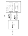
図1は、本開示のいくつかの実施形態に従って、レギュレートされた電力供給及びレギュレートされていない電力供給を供給するPSUを備えた高レベルシステム100を表す。いくつかの実施形態において、システム100は、PSU101、第1の電力供給ノード、第2の電力供給ノード、及び負荷102を有する。いくつかの実施形態において、PSU101は、AC又はDC電力供給を受け、レギュレートされた電力供給を第1の電力供給ノードにおいて、及びレギュレートされていない電力供給を第2の電力供給ノードにおいて生成する。いくつかの実施形態において、負荷102は、第1及び第2の電力供給ノードへ結合される。いくつかの実施形態において、複数の並列負荷102へ給電するよう並列に作動する1つよりも多いPSU101が存在してよい。
FIG. 1 represents a high-
様々な実施形態は、サーバである負荷102を参照して記載され、一方で、負荷102は、種々のタイプの負荷を有しているプロセッサシステム(例えば、タブレット、スマートデバイス)のような他の負荷であることができる。いくつかの実施形態において、負荷1 103は、レギュレートされた電力供給を最適な動作のために必要とする又は望む負荷である。負荷1 103の例には、ファンのような冷却エージェント、ハードディスクドライブ、などが含まれる。いくつかの実施形態において、第1の電力供給ノードは負荷1 103へ結合される。いくつかの実施形態において、第1の電力供給ノードにおけるレギュレートされた電力供給は、厳しい範囲(例えば、±5%)内に厳密にレギュレートされる。 Various embodiments are described with reference to a load 102 that is a server, while load 102 may be other such as processor systems (eg, tablets, smart devices) having various types of loads. Can be a load. In some embodiments, load 1103 is a load that requires or desires a regulated power supply for optimal operation. Examples of the load 1103 include a cooling agent such as a fan, a hard disk drive, and the like. In some embodiments, the first power supply node is coupled to load 1103. In some embodiments, the regulated power supply at the first power supply node is strictly regulated within a tight range (eg, ± 5%).
いくつかの実施形態において、負荷2 104は、高電力供給モード(例えば、ターボモード)の間により高い電力供給レベルで作動し得る負荷である。負荷2 104の例には、中央演算処理装置(CPU;central processing unit(s))、システム・オン・チップ(SoC;System-on-Chip)プロセッサ、チェーン又はリングにおいて結合された複数のプロセッサ、などに給電するための電圧レギュレータ(VR;voltage regulator(s))及びDC−DCコンバータが含まれる。いくつかの実施形態において、第2の電力供給ノードは負荷2 104へ結合される。いくつかの実施形態において、第2の電力供給ノードにおけるレギュレートされていない電力供給は、高電力モードが有効にされるときに一時的に大きく垂下することを許容される(なぜなら、それはレギュレートされていないので。)。 In some embodiments, load 2 104 is a load that can operate at a higher power supply level during a high power supply mode (eg, turbo mode). Examples of load 2 104 include a central processing unit (CPU), a system-on-chip (SoC) processor, a plurality of processors coupled in a chain or ring, Voltage regulators (VR) and DC-DC converters are included. In some embodiments, the second power supply node is coupled to load 2 104. In some embodiments, the unregulated power supply at the second power supply node is allowed to drastically droop temporarily when the high power mode is enabled (because it is regulated). Because it is not.)
いくつかの実施形態において、システム100は、PSU101及び負荷102が同じマザーボード又はダイにあるように、完全に統合されたシステムである。いくつかの実施形態において、PSU101は、PSU101がそれ自身のパッケージによる別個の集積回路である点で、負荷102から分離する。
In some embodiments,
図2は、本開示のいくつかの実施形態に従って、図1のPSU101の詳細レベルアーキテクチャ200を表す。いずれかの他の図の要素と同じ参照符号(又は名称)を有している図2の要素は、記載されているのと同様の如何なる様態においても作動又は機能することができるが、そのように制限されない点が指摘される。
FIG. 2 depicts the level of
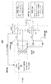
いくつかの実施形態において、PSU101は、1次側変換ユニット201、変圧器202、2次側整流器203及び204、インダクタL1及びL2、並びに出力キャパシタC1及びC2を有する。いくつかの実施形態において、1次側変換ユニット201は、AC又はDC電力供給源からAC電力供給を受け、高周波AC電力供給を生成する。1次側変換ユニット201は、整流器、位相周波数コントローラ、フルブリッジトポロジ変換回路、などを有する。いくつかの実施形態において、1次側変換ユニット201からのAC電力供給は、変圧器202の1次側巻線(すなわち、コイル)によって受け取られる。いくつかの実施形態において、変圧器202は、変圧器202の2次巻線においてAC電力供給を逓減する。
In some embodiments, the
いくつかの実施形態において、2つの整流器(203及び204)は、第1の整流器(すなわち、2次側整流器203)が電圧を第1のインダクタL1へ整流された供給するために使用され、一方、第2の整流器(すなわち、2次側整流器204)が第2のインダクタL2へ整流された電圧を供給するために使用されるように、変圧器202の2次側へ結合される。いくつかの実施形態において、2次側整流器203は、2つの整流回路又はデバイス(例えば、ダイオード)を含み、それらの一方は変圧器202の2次側巻線の第1の端子へ結合され、それらの他方は変圧器202の2次側巻線の第2の端子へ結合される。
In some embodiments, two rectifiers (203 and 204) are used to supply the first rectifier (ie, secondary rectifier 203) rectified to the first inductor L1, while , Coupled to the secondary side of
いくつかの実施形態において、2次側整流器204は、2つの整流回路又はデバイス(例えば、ダイオード)を含み、それらの一方は変圧器202の2次側巻線の第1の端子へ結合され、それらの他方は変圧器202の2次側巻線の第2の端子へ結合される。この実施形態では、両方の2次側整流器203及び204が変圧器202の同じ2次側巻線を共有する。いくつかの実施形態において、2次側整流器203及び204は、変圧器202の異なる2次側へ結合され、このとき、それらの異なる2次側は異なる数のコイルを有する。
In some embodiments,
いくつかの実施形態において、インダクタL1の第1の端子は2次側整流器203へ結合され、インダクタL1の第2の端子はVout1(第1の電力供給ノードともここでは称される。)へ結合される。ここで、ノード及びそれらのノードにおける信号のためのラベルは、交換可能に使用される。例えば、Vout1は、文脈に応じてVout1ノード又は電力供給Vout1を指してよい。いくつかの実施形態において、キャパシタC1は、Vout1及び接地へ結合される。いくつかの実施形態において、Vout1は、レギュレートされた電力供給(第1の電力供給とも称される。)を供給する。第1の電力供給は、第1の電力供給をレギュレートするよう1次側変換ユニット201へ(フィードバック経路を介して)フィードバックされる。いくつかの実施形態において、第1の電力供給(例えば、12V)は、厳密にレギュレートされる(例えば、±5%)。
In some embodiments, the first terminal of inductor L1 is coupled to
いくつかの実施形態において、インダクタL2の第1の端子は2次側整流器204へ結合され、インダクタL2の第2の端子はVout2(第2の電力供給ノードとも称される。)へ結合される。いくつかの実施形態において、キャパシタC2は、Vout2及び接地へ結合される。いくつかの実施形態において、Vout2は、レギュレートされていない電力供給(第2の電力供給とも称される。)を供給する。いくつかの実施形態において、第2の電力供給は、間接的にレギュレートされる(すなわち、弱レギュレートされる)。これは、第2の電力供給が、第1の電力供給をレギュレートする1次側変換ユニット201の出力から得られるからである。いくつかの実施形態において、Vout2と1次側変換ユニット201との間にはフィードバック経路は設けられない。従って、Vout2電力供給(例えば、12V)は、技術的にレギュレートされず、一時的な負荷の増大の間に垂下しうる(例えば、ターボモードの開始時の電圧垂下により12Vから6Vに落ちうる)。
In some embodiments, the first terminal of inductor L2 is coupled to
図3は、本開示のいくつかの実施形態に従って、レギュレートされた電力供給及びレギュレートされていない電力供給を供給する電力供給ユニット及び複数のサーバを備えたサーバラック300を表す。いずれかの他の図の要素と同じ参照符号(又は名称)を有している図3の要素は、記載されているのと同様の如何なる様態においても作動又は機能することができるが、そのように制限されない点が指摘される。
FIG. 3 depicts a
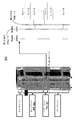
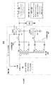
いくつかの実施形態において、サーバラック300は、PSU101のような1つ以上の電力供給ユニットを有しているパワーゾーン(Power Zone)と、複数のサーバ(すなわち、負荷102)を有しているサーバゾーン(Server Zone)と、ルータを有しているスイッチゾーン(Switch Zone)とを含む。いくつかの実施形態において、PSU101は、第1及び第2の電力供給を2つの別個の電力ノード(又はバスバー(BusBar(s)))において供給する。それらのノード(接地(GND)ノードを含む。)は、第1及び第2の電力供給を夫々のトレイ(tray)(Nが整数であるとして、トレイ1〜N)へ供給する。夫々のトレイは、1つ以上のプロセッサを有しているサーバを含む。いくつかの実施形態において、高電力モードの間、第1の電力供給はレギュレートされたままであり、一方、第2の電力供給は一時的に垂下しうる。
In some embodiments,
図4Aは、本開示のいくつかの実施形態に従って、エネルギ転送ユニットへ結合されている図1のPSU101を有する詳細レベルアーキテクチャ400を表す。いずれかの他の図の要素と同じ参照符号(又は名称)を有している図4Aの要素は、記載されているのと同様の如何なる様態においても作動又は機能することができるが、そのように制限されない点が指摘される。図4Aの実施形態を不明りょうにしないように、図2と図4Aとの間の相違が記載される。
FIG. 4A represents a level of
いくつかの実施形態において、エネルギ転送ユニット401は、第1及び第2の電力供給ノード(すなわち、Vout1及びVout2)へ結合される。実施形態は、PSU101の外にあるエネルギ転送ユニット401を示すが、いくつかの実施形態において、エネルギ転送ユニット401はPSU101の部分である。いくつかの実施形態において、エネルギ転送ユニット401は、Vout1からVout2への一方向のエネルギ転送及び低インピーダンス経路を提供するよう動作可能である。いくつかの実施形態において、制御信号(図示せず。)は、エネルギ転送ユニット401によって受信されて、エネルギ転送ユニット401にエネルギ転送の動作を開始させる。
In some embodiments,
エネルギ転送ユニット401の1つの技術的効果は、それが高電力モードトランジェントの間の第2の電力供給Vout2における垂下を補償することである(すなわち、エネルギは、高電力モードの間に電力供給能力を強化するよう、Vout1から取り入れられてVout2へ供給される。)。いくつかの実施形態において、制御信号は、Vout1の電圧レベルが閾値を上回る(例えば、通常の電圧レベルのうちの3%を上回る)ときに、エネルギ転送動作をトリガする。その期間中に、エネルギは第1の電力供給ノード(Vout1)から第2の電力供給ノード(Vout2)へ移る。いくつかの実施形態において、制御信号は、Vout1の電圧レベルが同じ閾値又は他の閾値を下回るときに、エネルギ転送ユニット401にエネルギ転送のプロセスを中止させる。
One technical effect of the
いくつかの実施形態において、制御信号は、第1の電力供給ノードでの電圧を検知する回路によって生成される。いくつかの実施形態において、制御信号は、第2の電力供給ノードを流れる電流方向を検知する回路によって生成される。電流の方向は、電流要求が突然に増大したかどうかを示し、そうである場合に、回路はエネルギ転送のプロセスを開始する。いくつかの実施形態において、制御信号を生成する回路はPSU101の部分である。いくつかの実施形態において、第2の電力供給ノードを流れる電流がその通常の電流値を上回ることを回路が検出するとき、回路は高電力モードを決定する。
In some embodiments, the control signal is generated by a circuit that senses the voltage at the first power supply node. In some embodiments, the control signal is generated by a circuit that senses the direction of current flowing through the second power supply node. The direction of the current indicates whether the current demand has suddenly increased, and if so, the circuit begins the process of energy transfer. In some embodiments, the circuit that generates the control signal is part of the
高電力モードがトリガされるとき、PSU101は、いくつかの実施形態に従って、更なるエネルギを1次側変換ユニット201から変圧器202へ転送するようスイッチングデューティサイクルを広げる。その期間中に、PSU101はまた、第2の電力供給ノード(Vout2)を更に支援してより高い電力供給の要求を満足するよう、エネルギ転送ユニット401にVout1からVout2へのエネルギ転送を開始させる。いくつかの実施形態において、第2の電力供給ノードを流れる電流がその通常レベルを下回るとき、PSU101はエネルギ転送ユニット401を無効にする。
When the high power mode is triggered, the
図4Bは、本開示のいくつかの実施形態に従って、PSU101の変圧器がふた組の2次側巻線を含む場合について、エネルギ変換ユニットへ結合されている図1のPSU101を有する詳細レベルアーキテクチャ420を表す。いずれかの他の図の要素と同じ参照符号(又は名称)を有している図4Bの要素は、記載されているのと同様の如何なる様態においても作動又は機能することができるが、そのように制限されない点が指摘される。図4Bの実施形態を不明りょうにしないように、図2と図4Bとの間の相違が記載される。
FIG. 4B illustrates a level of
いくつかの実施形態において、異なる組の巻線が変圧器402の2次側のために使用される。いくつかの実施形態において、2次側のためのひと組の巻線(Ts1)は、2次側整流器203へ結合され、2次側のための他の組の巻線(Ts2)は、2次側整流器404へ結合される。2次側整流器404は、その入力部が2次側整流器203へ結合されておらず、代わりに変圧器402の他の組の2次側巻線へ結合されている点を除いて、2次側整流器204と同様である。2つの整流器(203及び404)のための変圧器402の2次側のために異なる組の巻線を使用する1つの技術的効果は、より多くの電力が高電力モードの間に第2の電力供給V2へ供給され得る点である。
In some embodiments, a different set of windings is used for the secondary side of the transformer 402. In some embodiments, one set of windings (Ts1) for the secondary side is coupled to the
いくつかの実施形態において、Ts2は、Ts1よりも多い巻数を有している。Ts1の巻数よりもTs2の巻数を多くすることによって、キャパシタC2は、第2の電力供給ノードVout2でのより高い出力電圧により、より多くのエネルギを蓄えることができる。いくつかの実施形態において、2次側整流器203及び404は、エネルギ転送ユニット401がない場合は、異なる組の2次巻線へ結合されてよい。いくつかの実施形態において、2次側整流器203及び404は、エネルギ転送ユニット401とともに異なる組の巻線へ結合されてよい。
In some embodiments, Ts2 has more turns than Ts1. By increasing the number of turns of Ts2 over the number of turns of Ts1, the capacitor C2 can store more energy due to the higher output voltage at the second power supply node Vout2. In some embodiments,
図4Cは、本開示のいくつかの実施形態に従って、エネルギ転送ユニット430(例えば、401)を表す。いずれかの他の図の要素と同じ参照符号(又は名称)を有している図4Cの要素は、記載されているのと同様の如何なる様態においても作動又は機能することができるが、そのように制限されない点が指摘される。 FIG. 4C depicts an energy transfer unit 430 (eg, 401) according to some embodiments of the present disclosure. Elements of FIG. 4C that have the same reference number (or name) as any other figure element may operate or function in any manner similar to that described, but It is pointed out that it is not limited to.
いくつかの実施形態において、エネルギ転送ユニット430は、スイッチS1、制御ロジック431、及びインダクタL3を有する。いくつかの実施形態において、制御ロジック431は、第1の電力供給ノード(Vout1)から第2の電力供給ノード(Vout2)への電流の方向を示す電流検知信号を受信し、スイッチS1のオン/オフ切り替えを制御するオン/オフ制御信号を生成する。いくつかの実施形態において、負荷2 104が高電力モードに入るとき、PSU101はスイッチS1を(例えば、制御ロジック431に指示することによって)オンして、第1の電力供給ノードから第2の電力供給ノードへの電気経路を形成する。
In some embodiments, the energy transfer unit 430 includes a switch S1,
いくつかの実施形態において、インダクタL3は、スイッチS1及び第2の電力供給ノードVout2へ結合される。いくつかの実施形態において、インダクタL3のインダクタンスは、インダクタL1及びL2のインダクタンスよりも小さい。インダクタL3を有する1つの目的は、スイッチS1の動作及びインテグリティを保護するよういくつかの条件下で(例えば、Vout2とVout1との間の電圧差が約6Vである場合に)スイッチS1に高すぎるピーク突入電流(in-rush current)が流れることを回避することである。 In some embodiments, the inductor L3 is coupled to the switch S1 and the second power supply node Vout2. In some embodiments, the inductance of inductor L3 is less than the inductances of inductors L1 and L2. One purpose with inductor L3 is too high for switch S1 under some conditions (eg, when the voltage difference between Vout2 and Vout1 is about 6V) to protect the operation and integrity of switch S1. It is to avoid the flow of peak in-rush current.
いくつかの実施形態において、スイッチS1がオンされるとき、制御ロジック431は、ノードVout1とVout2の間を流れる電流の方向をモニタする。いくつかの実施形態において、制御ロジック431が電流方向の反転を検出するとき、それは、スイッチS1をオフさせる(すなわち、Vout1からVout2への電気経路が切断される。)。
In some embodiments, when switch S1 is turned on,
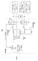
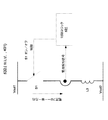
図5は、本開示のいくつかの実施形態に従って、レギュレートされた電力供給及びレギュレートされていない電力供給を生成するために使用される中間のアンレギュレート又はレギュレート電圧バスを有するPSU501を備えたアーキテクチャ500を表す。いずれかの他の図の要素と同じ参照符号(又は名称)を有している図5の要素は、記載されているのと同様の如何なる様態においても作動又は機能することができるが、そのように制限されない点が指摘される。図5の実施形態を不明りょうにしないように、図5と図2との間の相違が記載される。
FIG. 5 illustrates a
いくつかの実施形態において、アーキテクチャ500は、PSU501の‘m’個のインスタンスと、コンバータ502の‘x’個のインスタンスとを有する。いくつかの実施形態において、PSU501の‘m’個のインスタンスの全出力電力容量は、コンバータ502の‘x’個のインスタンスによって全所要電力を供給するに足りるほど高いべきである。いくつかの実施形態において、PSU501は、図示されるように一緒に結合されている1次側変換ユニット201、変圧器502、整流器503、インダクタL、及び出力キャパシタCを有する。いくつかの実施形態において、PSU501の出力は、単一電力レール(バスとして実装される。)であり、これは次いで、高電力モードを管理するよう2つの電力レールを提供するために使用される。ノード506にあるこの単一電力レール(すなわち、バス)の電圧は、レギュレートされても又はレギュレートされなくてもよく、コンバータ502のための入力電力となる。
In some embodiments,
いくつかの実施形態において、インダクタLは、整流器503及び中間バスノード506へ結合される。大規模システムでは、より高い電圧(例えば、48V)で中間バス506において電力を分配することが有利でありうる。電圧は、最終的な負荷電圧を生成するためにバルクコンバータを使用する直接変換のための直接的に適した電圧でなくてよい。いくつかの実施形態において、中間バス506からの出力電圧及び電流は、レギュレートされた電圧Vout1(すなわち、第1の電力供給)及びレギュレートされていない電圧Vout2(すなわち、第2の電力供給)を生成するようコンバータへ供給される。
In some embodiments, inductor L is coupled to rectifier 503 and
いくつかの実施形態において、コンバータ502の‘x’個のインスタンスは、図示されるように、コンバータ504及びバスコンバータ(X:1の比を有する。)505を有する。いくつかの実施形態において、コンバータ504は、中間電力バス506において中間電力を受け、レギュレートされたVout1を生成する。いくつかの実施形態において、バスコンバータ505は、中間電力バス506において中間電力を受け、レギュレートされていないVout2を生成する。いくつかの実施形態において、バスコンバータ505はDC−DCコンバータである。
In some embodiments, 'x' instances of converter 502 have
いくつかの実施形態において、バスコンバータ505による変換はレギュレートされない。例えば、出力電圧Vout2は、固定比‘X’によって入力電圧に追随する(例えば、‘X’が4であるとき、48Vを12Vへ)。中間バス506における入力電圧が変化するにつれて、出力電圧Vout2も変化する。レギュレートされた電力供給を有することを望む負荷のために、コンバータ504は、レギュレートされた出力電圧Vout1を供給するために使用される。そのような実施形態では、中間バス506における電圧が変化するとき、出力電圧Vout1は実質的に変化しないままである(例えば、±5%内でレギュレートされる。)。アーキテクチャ500は、Vout2のために広範な電圧範囲を提供し、それにより、Vout2へ結合される下流負荷は、他の負荷へ供給される電力供給Vout1に対して垂下を引き起こすことなしに、高電力モードで動作し得る。
In some embodiments, conversion by bus converter 505 is not regulated. For example, the output voltage Vout2 follows the input voltage by a fixed ratio ‘X’ (for example, when ‘X’ is 4, 48V to 12V). As the input voltage at the
いくつかの実施形態において、コンバータ504はバック(Buck)コンバータである。いくつかの実施形態において、コンバータ504は、約X:1の比を有しながらレギュレートされた出力を有するDC−DCコンバータである。いくつかの実施形態において、コンバータ504はバックブースト(Buck-Boost)コンバータである。そのような実施形態では、バスコンバータ505の出力は、コンバータ504への入力506の代わりに、コンバータ504への入力として供給される。
In some embodiments,
図6は、本開示のいくつかの実施形態に従って、レギュレートされた電力供給及びレギュレートされていない電力供給を供給する方法についてのフローチャート600を表す。いずれかの他の図の要素と同じ参照符号(又は名称)を有している図6の要素は、記載されているのと同様の如何なる様態においても作動又は機能することができるが、そのように制限されない点が指摘される。
FIG. 6 depicts a
図6を参照するフローチャートにおけるブロックは特定の順序において示されているが、アクションの順序は変更されてよい。よって、表されている実施形態は異なる順序で実施されてよく、いくつかのアクション/ブロックは並行して実施されてよい。図6において挙げられているブロック及び/動作のいくつかは、特定の実施形態に従って任意である。提示されているブロックの番号付けは、明りょうさのためであり、様々なブロックが起こるべき動作の順序を定めることは意図されない。加えて、様々なフローからの動作は、様々な組み合わせにおいて利用されてよい。 Although the blocks in the flowchart with reference to FIG. 6 are shown in a particular order, the order of actions may be changed. Thus, the illustrated embodiments may be performed in a different order and some actions / blocks may be performed in parallel. Some of the blocks and / or operations listed in FIG. 6 are optional according to certain embodiments. The block numbering presented is for clarity and is not intended to define the order in which the various blocks should occur. In addition, operations from various flows may be utilized in various combinations.
ブロック601で、レギュレートされた電力供給Vout1は、第1の2次側整流器203から第1の電力供給ノードVout1へ供給される。ブロック602で、第2の2次側整流器204又は404からのレギュレートされていない電力供給Vout2は、第2の電力供給ノードVout2へ供給される。第1及び第2の2次側整流器(203及び204/404)は、図2及び4を参照して示されるように、変圧器202へ結合される。再び図6を参照すると、ブロック603で、AC電力供給は、1次側変換ユニット201によって、変圧器202のための高周波AC電力供給へ変換される。ブロック604で、エネルギ転送ユニット401は、Vout2へ結合される負荷2 104が高電力モードに入るときに、電力を第1の電力供給ノードVout1から第2の電力供給ノードVout2へ転送してよい。
At
開示されている対象の実施形態を実装するよう実行される、フローチャート600に関連したプログラムソフトウェアコード/命令は、「プログラムソフトウェアコード/命令」、「オペレーティングシステムプログラムソフトウェアコード/命令」、「アプリケーションプログラムソフトウェアコード/命令」、又は単に「ソフトウェア」と呼ばれるオペレーティングシステム若しくは特定のアプリケーション、コンポーネント、プログラム、オブジェクト、モジュール、ルーチン、又は命令の他のシーケンス若しくは命令のシーケンスの編成、あるいは、プロセッサに埋め込まれたファームウェアの部分として実装されてよい。いくつかの実施形態において、フローチャート600に関連したプログラムソフトウェアコード/命令は、PSU101のコントローラによって実行される。
The program software code / instructions associated with
いくつかの実施形態において、フローチャート600に関連したプログラムソフトウェアコード/命令は、コンピュータ実行可能記憶媒体において記憶され、PSU101のコントローラによって実行される。ここで、コンピュータ実行可能記憶媒体は、コンピューティングデバイスによって実行される場合に、プロセッサ(例えば、PSU101のコントローラ)に、開示されている対象に向けられている1つ以上の添付の請求項において記載され得る方法を実施させるプログラムソフトウェアコード/命令及びデータを記憶するために使用され得る有形なマシン読み出し可能な媒体である。
In some embodiments, the program software code / instructions associated with
有形なマシン読み出し可能な媒体は、本願において参照されるような、例えば、ROM、揮発性RAM、不揮発性メモリ及び/又はキャッシュ及び/又は他の有形なメモリを含め、様々な有形な場所における実行可能なソフトウェアプログラムコード/命令の記憶を含んでよい。このプログラムソフトウェアコード/命令及び/又はデータの部分は、それらの記憶及びメモリデバイスのうちのいずれか1つにおいて記憶されてよい。更には、プログラムソフトウェアコード/命令は、例えば、中央集権化サーバ又はピア・ツー・ピアネットワーク及び同様のもの(インターネットを含む。)を経由することを含め、他のストレージから取得されてよい。ソフトウェアプログラムコード/命令及びデータの異なる部分は、異なる時点に、且つ、異なる通信セッションにおいて又は同じ通信セッションにおいて、取得されてよい。 A tangible machine readable medium may execute in various tangible locations, including, for example, ROM, volatile RAM, non-volatile memory and / or cache and / or other tangible memory as referred to herein. It may include storage of possible software program code / instructions. This portion of program software code / instructions and / or data may be stored in any one of their storage and memory devices. Furthermore, program software code / instructions may be obtained from other storage, including, for example, via a centralized server or peer-to-peer network and the like (including the Internet). Different portions of the software program code / instructions and data may be obtained at different times and in different communication sessions or in the same communication session.
ソフトウェアプログラムコード/命令(フローチャート600に関連する。)及びデータは、コンピューティングデバイスによる夫々のソフトウェアプログラム又はアプリケーションの実行より前にその全体を取得されてよい。代替的に、ソフトウェアプログラムコード/命令及びデータの部分は、実行のために必要とされる場合に動的に、例えば、いよいよと言うときに、取得されてよい。代替的に、ソフトウェアプログラムコード/命令及びデータを取得するそれらの方法のいくつかの組み合わせは、一例として、例えば、異なるアプリケーション、コンポーネント、プログラム、オブジェクト、モジュール、ルーチン、又は命令の他のシーケンス若しくは命令のシーケンスの編成のために、現れてよい。よって、データ及び命令は、全体が特定の時点に有形なマシン読み出し可能な媒体にあることを必要とされない。 Software program code / instructions (related to flowchart 600) and data may be obtained in its entirety prior to execution of the respective software program or application by the computing device. Alternatively, the portions of software program code / instructions and data may be obtained dynamically as needed for execution, for example, when it comes to time. Alternatively, some combination of software program code / instructions and those methods of obtaining data may be used as an example, eg, different applications, components, programs, objects, modules, routines, or other sequences or instructions of instructions. May appear because of the organization of the sequence. Thus, the data and instructions are not required to be entirely on a tangible machine readable medium at a particular time.
有形なコンピュータ読み出し可能な媒体の例は、とりわけ、揮発性及び不揮発性メモリデバイス、リードオンリーメモリ(ROM;read only memory)、ランダムアクセスメモリ(RAM;random access memory)、フラッシュメモリデバイス、フロッピー(登録商標)及び他のリムーバブルディスク、磁気ディスク記憶媒体、光記憶媒体(例えば、コンパクトディスク・リードオンリーメモリ(CD−ROM)、デジタルバーサタイルディスク(DVD;Digital Versatile Disc)、など)のような追記型及び非追記型媒体を含むが、それらに限られない。ソフトウェアプログラムコード/命令は、搬送波、赤外線信号、デジタル信号などのような信号をデジタルの有形な通信リンクを通じて伝播する電気的な、光学的な、音響的な、又は他の形態を実装しながら、そのような有形な通信リンクにおいて一時的に記憶されてよい。 Examples of tangible computer readable media include, among other things, volatile and non-volatile memory devices, read only memory (ROM), random access memory (RAM), flash memory devices, floppy (registered) Trademark) and other removable disks, magnetic disk storage media, optical storage media (eg, compact disc / read only memory (CD-ROM), digital versatile disc (DVD), etc.) and Including, but not limited to, non-recordable media. Software program code / instructions implement electrical, optical, acoustic, or other forms of propagation of signals such as carrier waves, infrared signals, digital signals, etc. through digital tangible communication links, It may be temporarily stored in such a tangible communication link.
一般に、有形なマシン読み出し可能な媒体は、インターネットのような通信ネットワークからアプリケーション及び補助アプリケーションをダウンロードし実行することが可能であろうとなかろうと、iPhone(登録商標)、Blackberry(登録商標)、Droid(登録商標)若しくは同様のもの、又はコンピューティングデバイスを含む何らかの他のデバイスのような、例えば、通信デバイス、コンピューティングデバイス、ネットワークデバイス、パーソナルデジタルアシスタント、製造ツール、モバイル通信デバイスにおいて含まれ得るマシン(すなわち、コンピューティングデバイス)によってアクセス可能な形で情報を提供する(すなわち、デジタル形式、例えば、データパケットにおいて、記憶及び/又は送信する)如何なる有形なメカニズムも含む。一実施形態において、プロセッサに基づくシステムは、PDA、携帯電話機、ノートブックコンピュータ、タブレット、ゲーム機、セットトップボックス、組み込みシステム(embedded system)、TV、パーソナルデスクトップコンピュータ、などの形をとり、あるいは、その中に含まれる。代替的に、従来の通信アプリケーション及び補助アプリケーションは、開示されている対象のいくつかの実施形態において使用されてよい。 In general, a tangible machine-readable medium can be used to download and execute applications and auxiliary applications from a communication network such as the Internet, iPhone®, Blackberry®, Droid ( Registered trademark or the like, or any other device including a computing device, such as a communication device, computing device, network device, personal digital assistant, manufacturing tool, machine that can be included in a mobile communication device ( That is, provide information in a form accessible by a computing device (ie, store and / or transmit in digital form, eg, data packets) ) Include any tangible mechanism. In one embodiment, the processor-based system takes the form of a PDA, mobile phone, notebook computer, tablet, game console, set-top box, embedded system, TV, personal desktop computer, etc., or Included in it. Alternatively, conventional communication applications and auxiliary applications may be used in some embodiments of the disclosed subject matter.
図7は、本開示のいくつかの実施形態に従って、レギュレートされた電力供給及びレギュレートされていない電力供給を供給するPSUを有するスマートデバイス又はコンピュータシステム又はSoC(System-on-Chip)を表す。いずれかの他の図の要素と同じ参照番号(又は名称)を有している図7の要素は、記載されているのと同様にして作動又は機能することができるが、そのように制限されないことが指摘される。 FIG. 7 depicts a smart device or computer system or SoC (System-on-Chip) having a PSU that provides a regulated power supply and an unregulated power supply, according to some embodiments of the present disclosure. . Elements of FIG. 7 that have the same reference numbers (or names) as any other figure element may operate or function in the same manner as described, but are not so limited. It is pointed out.
図7は、平面(flat surface)インターフェイスコネクタが使用されうるモバイルデバイスの実施形態のブロック図を表す。一実施形態において、コンピューティングデバイス1600は、コンピューティングタブレット、携帯電話機若しくはスマートフォン、無線対応電子リーダー、又は他の無線モバイルデバイスのような、モバイルコンピューティングデバイスに相当する。特定のコンポーネントは一般的に示されており、そのようなデバイスの全てのコンポーネントがコンピューティングデバイス1600において示されているわけでないことが理解されるだろう。
FIG. 7 depicts a block diagram of an embodiment of a mobile device in which a flat surface interface connector may be used. In one embodiment,
一実施形態において、コンピューティングデバイス1600は、論じられているいくつかの実施形態に従って、レギュレートされた電力供給及びレギュレートされていない電力供給を供給する又は供給させるPSU(例えば、PSU101、PSU501)を有する第1のプロセッサ1610を含む。コンピューティングデバイス1600の他のブロックも、いくつかの実施形態に従って、レギュレートされた電力供給及びレギュレートされていない電力供給を供給する又は供給させるPSU(例えば、PSU101、PSU501)を有してよい。本開示の様々な実施形態は、無線インターフェイスのような、1670内のネットワークインターフェイスを更に有してよく、それにより、システムの実施形態は、無線デバイス、例えば、携帯電話機又はパーソナルデジタルアシスタントに組み込まれてよい。
In one embodiment, the
一実施形態において、プロセッサ1610(及び/又はプロセッサ1690)は、マイクロプロセッサ、アプリケーションプロセッサ、マイクロコントローラ、プログラム可能論理デバイス、又は他のプロセッシング手段のような、1つ以上の物理デバイスを含むことができる。プロセッサ1610によって実施されるプロセッシング動作は、アプリケーション及び/又はデバイス機能が実行されるオペレーティングプラットフォーム又はオペレーティングシステムの実行を含む。プロセッシング動作は、人間であるユーザによる若しくは他のデバイスによるI/O(input/output)に関連した動作、電力管理に関連した動作、及び/又はコンピューティングデバイス1600を他のデバイスへ接続することに関連した動作を含む。プロセッシング動作はまた、オーディオI/O及び/又はディスプレイI/Oに関連した動作を含んでよい。
In one embodiment, processor 1610 (and / or processor 1690) may include one or more physical devices, such as a microprocessor, application processor, microcontroller, programmable logical device, or other processing means. . Processing operations performed by
一実施形態において、コンピューティングデバイス1600は、オーディオサブシステム1620を含む。オーディオサブシステム1620は、オーディオ機能をコンピューティングデバイスへ提供することに関連したハードウェア(例えば、オーディオハードウェア及びオーディオ回路)並びにソフトウェア(例えば、ドライバ、コーデック)コンポーネントに相当する。オーディオ機能は、マイクロホン入力に加えて、スピーカ及び/又はヘッドホン出力を含むことができる。そのような機能のためのデバイスは、コンピューティングデバイス1600に組み込まれるか、あるいは、コンピューティングデバイス1600へ接続され得る。一実施形態において、ユーザは、プロセッサ1610によって受信されて処理される音声コマンドを供給することによって、コンピューティングデバイス1600と対話する。
In one embodiment,
ディスプレイサブシステム1630は、ユーザがコンピューティングデバイス1600と対話するための視覚的及び/又は触覚的な表示を提供するハードウェア(例えば、表示デバイス)及びソフトウェア(例えば、ドライバ)コンポーネントに相当する。ディスプレイサブシステム1630は、ディスプレイインターフェイス1632を含む。ディスプレイサブシステム1630は、表示をユーザに提供するために使用される特定のスクリーン又はハードウェアデバイスを含む。一実施形態において、ディスプレイインターフェイス1632は、表示に関連した少なくとも何らかのプロセッシングを実行するための、プロセッサ1610とは別個のロジックを含む。一実施形態において、ディスプレイサブシステム1630は、出力及び入力の両方をユーザへ提供するタッチスクリーン(又はタッチパッド)デバイスを含む。
Display subsystem 1630 corresponds to a hardware (eg, display device) and software (eg, driver) component that provides a visual and / or tactile display for a user to interact with
I/Oコントローラ1640は、ユーザとのインタラクションに関連したハードウェアデバイス及びソフトウェアコンポーネントに相当する。I/Oコントローラ1640は、オーディオサブシステム1620及び/又はディスプレイサブシステム1630の部分であるハードウェアを管理するよう動作可能である。加えて、I/Oコントローラ1640は、コンピューティングデバイスへ接続する追加のデバイスのための接続ポイントを表す。その追加のデバイスを通じて、ユーザはシステムと対話してよい。例えば、コンピューティングデバイス1600に取り付けられ得るデバイスは、マイクロホンデバイス、スピーカ若しくはステレオシステム、ビデオシステム若しくは他の表示デバイス、キーボード若しくはキーパッドデバイス、又はカードリーダー若しくは他のデバイスのような、特定の用途に使用される他のI/Oデバイスを含んでよい。
The I /
上述されたように、I/Oコントローラ1640は、オーディオサブシステム1620及び/又はディスプレイサブシステム1630と相互作用することができる。例えば、マイクロホン又は他のオーディオデバイスを通じた入力は、コンピューティングデバイス1600の1つ以上のアプリケーション又は機能のための入力又はコマンドを提供することができる。加えて、オーディオ出力は、ディスプレイ出力の代わりに、又はそれに加えて供給され得る。他の例において、ディスプレイサブシステム1630がタッチスクリーンを含む場合には、表示デバイスは入力デバイスとしても動作し、I/Oコントローラ1640によって少なくとも部分的に管理され得る。コンピューティングデバイス1600には、I/Oコントローラ1640によって管理されるI/O機能を提供するよう、追加のボタン又はスイッチが更に存在することができる。
As described above, the I /
一実施形態において、I/Oコントローラ1640は、加速度計、カメラ、光センサ若しくは他の環境センサ、又はコンピューティングデバイス1600に含まれ得る他のハードウェアのような、デバイスを管理する。入力は、システムの動作(例えば、ノイズのフィルタリング、輝度検出のための表示の調整、カメラのフラッシュ、又は他の機能)に作用するよう、環境入力をシステムに供給することに加えて、直接的なユーザインタラクションの部分であることができる。
In one embodiment, the I /
一実施形態において、コンピューティングデバイス1600は、バッテリ電力使用量、バッテリの充電、及び節電動作に関連した機能を管理する電力マネージメント1650を含む。メモリサブシステム1660は、コンピューティングデバイス1600において情報を記憶するメモリデバイスを含む。メモリは、不揮発性(メモリデバイスへの電力が中断される場合に状態が変化しない。)及び/又は揮発性(メモリデバイスへの電力が中断される場合に状態が不定である。)のメモリデバイスを含むことができる。メモリサブシステム1660は、コンピューティングデバイス1600のアプリケーション及び機能の実行に関連したシステムデータ(長期又は一時であろうとなかろうと。)に加えて、アプリケーションデータ、ユーザデータ、音楽、写真、文書、又は他のデータを記憶することができる。
In one embodiment, the
実施形態の要素は、コンピュータ実行可能命令(例えば、本願で論じられている如何なる他のプロセスも実施するための命令)を記憶するマシン読み出し可能な媒体(例えば、メモリ1660)としても提供される。マシン読み出し可能な媒体(例えば、メモリ1660)は、フラッシュメモリ、光ディスク、CD−ROM、DVD ROM、RAM、EPROM、EEPROM、磁気若しくは光学カード、相変化メモリ(PCM;phase change memory)、又は電子的な若しくはコンピュータ実行可能な命令を記憶するのに適した他のタイプのマシン読み出し可能な媒体を含んでよいが、それらに限られない。例えば、本開示の実施形態は、遠隔のコンピュータ(例えば、サーバ)から要求元のコンピュータ(例えば、クライアント)へ通信リンク(例えば、モデム又はネットワーク接続)を経由してデータ信号によって転送され得るコンピュータプログラム(例えば、BIOS)としてダウンロードされてよい。 Elements of the embodiments are also provided as machine-readable media (eg, memory 1660) that store computer-executable instructions (eg, instructions for performing any other processes discussed herein). Machine readable media (eg, memory 1660) may be flash memory, optical disc, CD-ROM, DVD ROM, RAM, EPROM, EEPROM, magnetic or optical card, phase change memory (PCM), or electronic Other types of machine-readable media suitable for storing computer-executable instructions may be included, but are not limited to them. For example, embodiments of the present disclosure are computer programs that can be transferred by a data signal from a remote computer (eg, a server) to a requesting computer (eg, a client) via a communication link (eg, a modem or a network connection). (Eg, BIOS) may be downloaded.
コネクティビティ(connectivity)1670は、コンピューティングデバイス1600が外部のデバイスと通信することを可能にするハードウェアデバイス(例えば、無線及び/又は有線コネクタ及び通信ハードウェア)並びにソフトウェアコンポーネント(例えば、ドライバ、プロトコルスタック)を含む。コンピューティングデバイス1600は、他のコンピューティングデバイス、無線アクセスポイント又は基地局のような別個のデバイス、及びヘッドセット、プリンタ、又は他のデバイスのような周辺機器であってよい。
Connectivity 1670 enables hardware devices (eg, wireless and / or wired connectors and communication hardware) and software components (eg, drivers, protocol stacks) that allow
コネクティビティ1670は、多種多様なタイプのコネクティビティを含むことができる。一般化するよう、コンピューティングデバイス1600は、セルラーコネクティビティ1672及びワイヤレスコネクティビティ1674を有して表されている。セルラーコネクティビティ1672は、例えば、GSM(登録商標)(global system for mobile communications)又は変形若しくは派生物、CDMA(code division multiple access)又は変形若しくは派生物、TDM(time division multiplexing)又は変形若しくは派生物、あるいは、他のセルラーサービス標準を介して提供されるような、無線キャリアによって提供されるセルラーネットワークコネクティビティを一般に指す。ワイヤレスコネクティビティ(又は無線インターフェイス)1674は、セルラーではないワイヤレスコネクティビティを指し、パーソナルエリアネットワーク(例えば、Bluetooth(登録商標)、Near Field、など)、ローカルエリアネットワーク(例えば、Wi−Fi(登録商標))、及び/又はワイドエリアネットワーク(例えば、WiMAX(登録商標))、あるいは、他の無線通信を含むことができる。
Connectivity 1670 may include a wide variety of types of connectivity. As generalized,
周辺機器接続1680は、周辺機器の接続を行うソフトウェアコンポーネント(例えば、ドライバ、プロトコルスタック)に加えて、ハードウェアインターフェイス及びコネクタを含む。コンピューティングデバイス1600は、他のコンピューティングデバイスに対する周辺機器であってよく(“to”1682)、更には、周辺機器を自身へ接続されてよい(“from”1684)。コンピューティングデバイス1600は、コンピューティングデバイス1600においてコンテンツを管理(例えば、ダウンロード及び/又はアップロード、変更、同期化)するといった目的のために、他のコンピューティングデバイスへ接続する“ドッキング”コネクタを一般に有している。加えて、ドッキングコネクタは、コンピューティングデバイス1600が、例えば、オーディオビジュアル又は他のシステムへのコンテンツ出力を制御することを可能にする特定の周辺機器へ接続することをコンピューティングデバイス1600に可能にすることができる。
独自仕様のドッキングコネクタ又は他の独自仕様の接続ハードウェアに加えて、コンピューティングデバイス1600は、共通の又は標準に基づいたコネクタを経由して周辺機器接続1680を行うことができる。共通のタイプは、ユニバーサルシリアルバス(USB)コネクタ(多種多様なハードウェアインターフェイスのいずれかを含むことができる。)、ミニディスプレイポート(MDP;MiniDisplayPort)を含むディスプレイポート、高精細マルチメディアインターフェイス(HDMI(登録商標);High Definition Multimedia Interface)、ファイアワイヤ(Firewire)、又は他のタイプを含むことができる。
In addition to a proprietary docking connector or other proprietary connection hardware, the
「実施形態(an embodiment)」、「一実施形態(one embodiment)」、「いくつかの実施形態(some embodiments)」又は「他の実施形態(other embodiments)」への明細書中の言及は、実施形態に関連して記載されている特定の特徴、構造、又は特性が少なくとも1つの実施形態に含まれるが、必ずしも全ての実施形態ではないことを意味する。「実施形態」、「一実施形態」又は「いくつかの実施形態」の様々な出現は、必ずしも全てが同じ実施形態に言及しているわけではない。明細書が、コンポーネント、特徴、構造、又は特性が“含まれてよい”、“含まれうる”又は“含まれることがある”(may、might又はcould include)と述べる場合に、その特定のコンポーネント、特徴、構造、又は特性は含まれることを要しない。明細書又は請求項がある(a又はan)要素に言及する場合に、それは、ただ1つの要素しか存在しないことを意味するものではない。明細書又は請求項が“追加の”(additional)要素に言及する場合に、それは、追加の要素が1つよりも多く存在することを除外しない。 References in the specification to "an embodiment", "one embodiment", "some embodiments" or "other embodiments" It is meant that a particular feature, structure, or characteristic described in connection with an embodiment is included in at least one embodiment, but not necessarily all embodiments. The various appearances of “an embodiment,” “one embodiment,” or “some embodiments” are not necessarily all referring to the same embodiment. A particular component when the specification states that the component, feature, structure, or characteristic may be “included”, “may be included” or “may be included” (may, might or could include) , Features, structures, or characteristics need not be included. When a specification or claim refers to an element (a or an), it does not mean that there is only one element. Where the specification or claims refer to “additional” elements, it does not exclude the presence of more than one additional element.
更には、特定の特徴、構造、機能、又は特性は、1つ以上の実施形態において如何なる適切な方法でも組み合わされてよい。例えば、第1及び第2の実施形態に関連した特定の特徴、構造、機能、又は特性が相互排他的でない場合にはいつでも、第1の実施形態は第2の実施形態と組み合わされてよい。 Furthermore, the particular features, structures, functions, or characteristics may be combined in any suitable manner in one or more embodiments. For example, the first embodiment may be combined with the second embodiment whenever a particular feature, structure, function, or property associated with the first and second embodiments is not mutually exclusive.
本開示は、その具体的な実施形態に関連して記載されてきたが、そのような実施形態の多数の代替案、変更及び変形は、前述の記載に照らして、当業者には明らかだろう。例えば、他のメモリアーキテクチャ、例えば、動的(dynamic)RAM(DRAM)は、論じられている実施形態を使用してよい。本開示の実施形態は、全てのそのような代替案、変更、及び変形例を、添付の特許請求の範囲の広い適用範囲内にあるように包含することを意図される。 While this disclosure has been described with reference to specific embodiments thereof, many alternatives, modifications, and variations of such embodiments will be apparent to those skilled in the art in light of the foregoing description. . For example, other memory architectures, such as dynamic RAM (DRAM), may use the discussed embodiments. The embodiments of the present disclosure are intended to embrace all such alternatives, modifications and variations that fall within the broad scope of the appended claims.
加えて、集積回路(IC;integrated circuit)チップ及び他のコンポーネントへのよく知られた電力/接地接続は、説明及び議論の簡単のために、更には、本開示を不明りょうにしないように、提示されている図の中で示されても示されなくてもよい。更には、配置は、ブロック図において、本開示を不明りょうにすることを回避するために、更には、そのようなブロック図配置の実施に関する仕様が、本開示が実装されるべきであるプラットフォームに大いに依存する(すなわち、そのような仕様は、当業者の視野内に十分にあるべきである。)という事実に照らして、図示されてよい。具体的な詳細(例えば、回路)が、本開示の例となる実施形態を記載するために示される場合に、当業者に当然ながら、本開示は、それらの具体的な詳細によらずに、又はその変形によって、実施されてよい。記載は、よって、限定ではなく実例と見なされるべきである。 In addition, well-known power / ground connections to integrated circuit (IC) chips and other components are presented for ease of explanation and discussion, and not to obscure the present disclosure. It may or may not be shown in the figures that are shown. In addition, the arrangements are not intended to obscure the disclosure in block diagrams, and moreover, specifications regarding the implementation of such block diagram arrangements are largely dependent on the platform on which the disclosure is to be implemented. It may be illustrated in the light of the fact that it depends (ie, such a specification should be well within the scope of those skilled in the art). Where specific details (eg, circuitry) are provided to describe exemplary embodiments of the present disclosure, it will be appreciated by those skilled in the art that the present disclosure, regardless of those specific details, Or it may be implemented by its modification. The description is thus to be regarded as illustrative instead of limiting.
以下の例は、更なる実施形態に関係がある。例における詳細は、1つ以上の実施形態においてどこでも使用されてよい。本願で記載される装置の全ての任意の特徴は、方法又はプロセスに関しても実装されてよい。 The following examples relate to further embodiments. Details in the examples may be used anywhere in one or more embodiments. All optional features of the devices described herein may also be implemented with respect to methods or processes.
例えば、変圧器と、第1の整流器と、第2の整流器とを有し、前記第1の整流器は、該第1の整流器がレギュレートされた電力供給を第1の電力供給ノードへ供給し、前記第2の整流器がレギュレートされていない電力供給を第2の電力供給ノードへ供給するように、前記変圧器へ結合される、装置が提供される。 For example, it has a transformer, a first rectifier, and a second rectifier, and the first rectifier supplies a regulated power supply to the first power supply node. , An apparatus is provided that is coupled to the transformer such that the second rectifier provides an unregulated power supply to a second power supply node.
いくつかの実施形態において、当該装置は、前記変圧器へ結合される変換ユニットを有する。いくつかの実施形態において、前記変換ユニットは、AC又はDC電源へ結合する1つ以上の入力部と、前記変圧器へ結合される1つ以上の出力部とを含む。いくつかの実施形態において、当該装置は、前記第1の整流器及び前記第1の電力供給ノードと直列に結合される第1のインダクタと、前記第1の電力供給ノード及び接地へ結合される第1のキャパシタとを有する。いくつかの実施形態において、当該装置は、前記第2の整流器及び前記第2の電力供給ノードと直列に結合される第2のインダクタと、前記第2の電力供給ノード及び接地へ結合される第2のキャパシタとを有する。 In some embodiments, the apparatus has a conversion unit coupled to the transformer. In some embodiments, the conversion unit includes one or more inputs coupled to an AC or DC power source and one or more outputs coupled to the transformer. In some embodiments, the apparatus includes a first inductor coupled in series with the first rectifier and the first power supply node, and a first inductor coupled to the first power supply node and ground. 1 capacitor. In some embodiments, the apparatus includes a second inductor coupled in series with the second rectifier and the second power supply node, and a second inductor coupled to the second power supply node and ground. 2 capacitors.
いくつかの実施形態において、当該装置は、前記第1の電力供給ノード及び前記第2の電力供給ノードへ結合されるエネルギ転送ユニットを有する。いくつかの実施形態において、前記エネルギ転送ユニットは、一方向性であり、エネルギを前記第1の電力供給ノードから前記第2の電力供給ノードへ運ぶよう動作する。いくつかの実施形態において、当該装置は、前記第1の電力供給ノード及び前記第2の電力供給ノードへ結合され、前記第1の電力供給ノード及び前記第2の電力供給ノードを流れる電流を検知し、前記エネルギ転送ユニットを制御する1つ以上の電流センサを有する。いくつかの実施形態において、前記変圧器は、第1の組の2次側巻線が前記第1の整流器へ結合され、第2の組の2次側巻線が前記第2の整流器へ結合されるように、ふた組の2次側巻線を有する。いくつかの実施形態において、前記変圧器の1次側巻線に対する前記第1の組の2次側巻線の巻線比は、前記1次側巻線に対する前記第2の組の2次側巻線の巻線比とは異なる。 In some embodiments, the apparatus comprises an energy transfer unit coupled to the first power supply node and the second power supply node. In some embodiments, the energy transfer unit is unidirectional and operates to carry energy from the first power supply node to the second power supply node. In some embodiments, the apparatus is coupled to the first power supply node and the second power supply node and senses current flowing through the first power supply node and the second power supply node. And having one or more current sensors for controlling the energy transfer unit. In some embodiments, the transformer includes a first set of secondary windings coupled to the first rectifier and a second set of secondary windings coupled to the second rectifier. As can be seen, it has a secondary set of secondary windings. In some embodiments, the turns ratio of the first set of secondary windings to the primary winding of the transformer is the second set of secondary windings to the primary winding. It is different from the winding ratio of the winding.
他の例において、レギュレートされた電力供給を第1の整流器から第1の電力供給ノードへ供給することと、レギュレートされていない電力供給を第2の整流器から第2の電力供給ノードへ供給することとを有し、前記第1の整流器及び前記第2の整流器は、変圧器へ結合される、方法が提供される。いくつかの実施形態において、当該方法は、AC又はDC電力供給を前記変圧器のための高周波AC電力供給へ変換することを有する。いくつかの実施形態において、当該方法は、前記第1の電力供給ノードからのフィードバックを変換ユニットへ供給することを有する。いくつかの実施形態において、当該方法は、前記第1の電力供給ノードから前記第2の電力供給ノードへ電力を運ぶことを有する。いくつかの実施形態において、当該方法は、いつ前記第1の電力供給ノードから前記第2の電力供給ノードへ電力を運ぶべきかを決定するよう、前記第1の電力供給ノード及び前記第2の電力供給ノードを流れる電流を検知することを有する。 In another example, a regulated power supply is provided from a first rectifier to a first power supply node and an unregulated power supply is provided from a second rectifier to a second power supply node. And the first rectifier and the second rectifier are coupled to a transformer. In some embodiments, the method comprises converting an AC or DC power supply to a high frequency AC power supply for the transformer. In some embodiments, the method comprises providing feedback from the first power supply node to the conversion unit. In some embodiments, the method comprises carrying power from the first power supply node to the second power supply node. In some embodiments, the method includes the first power supply node and the second power supply node to determine when to carry power from the first power supply node to the second power supply node. Sensing current flowing through the power supply node.
他の例において、第1の電力供給ノードを有するメモリと、該メモリへ結合され、第2の電力供給ノードを有するプロセッサと、上記に従う装置を有する電力供給ユニットと、前記プロセッサが他のデバイスと通信することを可能にする無線インターフェイスとを有するシステムが提供される。いくつかの実施形態において、前記プロセッサは、前記レギュレートされていない電力供給を受け、前記プロセッサの様々な負荷のためのレギュレートされた電力供給を生成する1つ以上の電圧レギュレータを含む。いくつかの実施形態において、当該システムは、前記第1の電力供給ノードへ結合される冷却ユニットを更に有する。
いくつかの実施形態において、レギュレートされた電力供給を第1の整流器から第1の電力供給ノードへ供給する手段と、レギュレートされていない電力供給を第2の整流器から第2の電力供給ノードへ供給する手段とを有し、前記第1の整流器及び前記第2の整流器は、変圧器へ結合される、装置が提供される。いくつかの実施形態において、当該装置は、AC又はDC電力供給を前記変圧器のための高周波AC電力供給へ変換する手段を有する。いくつかの実施形態において、当該装置は、前記第1の電力供給ノードからのフィードバックを変換ユニットへ供給する手段を有する。いくつかの実施形態において、当該装置は、前記第1の電力供給ノードから前記第2の電力供給ノードへ電力を運ぶ手段を有する。いくつかの実施形態において、当該装置は、いつ前記第1の電力供給ノードから前記第2の電力供給ノードへ電力を運ぶべきかを決定するよう、前記第1の電力供給ノード及び前記第2の電力供給ノードを流れる電流を検知する手段を有する。
In another example, a memory having a first power supply node, a processor coupled to the memory and having a second power supply node, a power supply unit having an apparatus according to the above, and wherein the processor is another device. A system is provided having a wireless interface that enables communication. In some embodiments, the processor includes one or more voltage regulators that receive the unregulated power supply and generate a regulated power supply for various loads of the processor. In some embodiments, the system further comprises a cooling unit coupled to the first power supply node.
In some embodiments, means for supplying a regulated power supply from the first rectifier to the first power supply node, and an unregulated power supply from the second rectifier to the second power supply node. Means for supplying to the apparatus, wherein the first rectifier and the second rectifier are coupled to a transformer. In some embodiments, the apparatus comprises means for converting an AC or DC power supply to a high frequency AC power supply for the transformer. In some embodiments, the apparatus comprises means for providing feedback from the first power supply node to the conversion unit. In some embodiments, the apparatus comprises means for carrying power from the first power supply node to the second power supply node. In some embodiments, the apparatus is configured to determine when to carry power from the first power supply node to the second power supply node, the first power supply node and the second power supply node. A means for detecting a current flowing through the power supply node;
他の例において、第1の電力供給ノードを有するメモリと、該メモリへ結合され、第2の電力供給ノードを有するプロセッサと、上記に従う装置を有する電力供給ユニットと、前記プロセッサが他のデバイスと通信することを可能にする無線インターフェイスとを有するシステムが提供される。いくつかの実施形態において、当該システムは、プロセッサによって処理されたコンテンツを表示することをディスプレイユニットに可能にするディスプレイインターフェイスを有する。 In another example, a memory having a first power supply node, a processor coupled to the memory and having a second power supply node, a power supply unit having an apparatus according to the above, and wherein the processor is another device. A system is provided having a wireless interface that enables communication. In some embodiments, the system has a display interface that allows the display unit to display content processed by the processor.
要約が与えられるが、これは、技術的開示の本質及び主旨を確かめることを読者に可能にするものである。要約は、特許請求の範囲の適用範囲及び意味を限定するために使用されないとの理解の下で提出される。続く特許請求の範囲は、これによって、詳細な説明に組み込まれ、各請求項は、別個の実施形態として自立する。 A summary is given, which allows the reader to ascertain the nature and spirit of the technical disclosure. It is submitted with the understanding that it will not be used to limit the scope and meaning of the claims. The following claims are hereby incorporated into the detailed description, with each claim standing on its own as a separate embodiment.
Claims (20)
第1の整流器と、
第2の整流器と
を有し、
前記第1の整流器は、該第1の整流器がレギュレートされた電力供給を第1の電力供給ノードへ供給し、前記第2の整流器がレギュレートされていない電力供給を第2の電力供給ノードへ供給するように、前記変圧器へ結合される、
装置。 A transformer,
A first rectifier;
A second rectifier and
The first rectifier supplies a power supply regulated by the first rectifier to a first power supply node, and a power supply not regulated by the second rectifier is supplied to a second power supply node. Coupled to the transformer to supply
apparatus.
を有する請求項1に記載の装置。 The apparatus of claim 1, comprising a conversion unit coupled to the transformer.
AC又はDC電源へ結合する1つ以上の入力部と、
前記変圧器へ結合される1つ以上の出力部と
を含む、請求項2に記載の装置。 The conversion unit is
One or more inputs coupled to an AC or DC power source;
The apparatus of claim 2, comprising one or more outputs coupled to the transformer.
前記第1の電力供給ノード及び接地へ結合される第1のキャパシタと
を有する請求項1に記載の装置。 A first inductor coupled in series with the first rectifier and the first power supply node;
The apparatus of claim 1, comprising: a first capacitor coupled to the first power supply node and ground.
前記第2の電力供給ノード及び接地へ結合される第2のキャパシタと
を有する請求項4に記載の装置。 A second inductor coupled in series with the second rectifier and the second power supply node;
The apparatus of claim 4, comprising: a second capacitor coupled to the second power supply node and ground.
を有する請求項1に記載の装置。 The apparatus of claim 1, comprising an energy transfer unit coupled to the first power supply node and the second power supply node.
請求項6に記載の装置。 The energy transfer unit is unidirectional and operates to carry energy from the first power supply node to the second power supply node;
The apparatus according to claim 6.
を有する請求項6に記載の装置。 One coupled to the first power supply node and the second power supply node, for sensing a current flowing through the first power supply node and the second power supply node and controlling the energy transfer unit The apparatus of Claim 6 which has the above current sensor.
請求項1に記載の装置。 The transformer includes a pair of lids such that a first set of secondary windings are coupled to the first rectifier and a second set of secondary windings are coupled to the second rectifier. Having a secondary winding of
The apparatus of claim 1.
請求項9に記載の装置。 The winding ratio of the secondary winding of the first set to the primary winding of the transformer is the winding ratio of the secondary winding of the second set to the primary winding and Is different,
The apparatus according to claim 9.
レギュレートされていない電力供給を第2の整流器から第2の電力供給ノードへ供給する手段と
を有し、
前記第1の整流器及び前記第2の整流器は、変圧器へ結合される、
装置。 Means for supplying a regulated power supply from the first rectifier to the first power supply node;
Means for supplying an unregulated power supply from the second rectifier to the second power supply node;
The first rectifier and the second rectifier are coupled to a transformer;
apparatus.
を有する請求項11に記載の装置。 12. The apparatus of claim 11, comprising means for converting an AC or DC power supply to a high frequency AC power supply for the transformer.
を有する請求項11に記載の装置。 The apparatus according to claim 11, further comprising means for supplying feedback from the first power supply node to the conversion unit.
を有する請求項11に記載の装置。 The apparatus of claim 11, comprising means for carrying power from the first power supply node to the second power supply node.
を有する請求項14に記載の装置。 Means for sensing currents flowing through the first power supply node and the second power supply node to determine when to carry power from the first power supply node to the second power supply node; The apparatus of claim 14.
前記メモリへ結合され、第2の電力供給ノードを有するプロセッサと、
電力供給ユニットと、
前記プロセッサが他のデバイスと通信することを可能にする無線インターフェイスと
を有し、
前記電力供給ユニットは、
変圧器と、
第1の整流器と、
第2の整流器と
を有し、
前記第1の整流器は、該第1の整流器がレギュレートされた電力供給を第1の電力供給ノードへ供給し、前記第2の整流器がレギュレートされていない電力供給を第2の電力供給ノードへ供給するように、前記変圧器へ結合される、
システム。 A memory having a first power supply node;
A processor coupled to the memory and having a second power supply node;
A power supply unit;
A wireless interface that enables the processor to communicate with other devices;
The power supply unit includes:
A transformer,
A first rectifier;
A second rectifier and
The first rectifier supplies a power supply regulated by the first rectifier to a first power supply node, and a power supply not regulated by the second rectifier is supplied to a second power supply node. Coupled to the transformer to supply
system.
請求項16に記載のシステム。 The processor includes one or more voltage regulators that receive the unregulated power supply and generate a regulated power supply for various loads of the processor.
The system of claim 16.
請求項16に記載のシステム。 The power supply unit includes an energy transfer unit coupled to the first power supply node and the second power supply node.
The system of claim 16.
請求項18に記載のシステム。 The energy transfer unit is unidirectional and operates to carry energy from the first power supply node to the second power supply node;
The system of claim 18.
を更に有する請求項16に記載のシステム。
The system of claim 16, further comprising a cooling unit coupled to the first power supply node.
Applications Claiming Priority (1)
| Application Number | Priority Date | Filing Date | Title |
|---|---|---|---|
| PCT/CN2014/087429 WO2016045052A1 (en) | 2014-09-25 | 2014-09-25 | Power supply unit adaptable for various power modes |
Publications (1)
| Publication Number | Publication Date |
|---|---|
| JP2017528113A true JP2017528113A (en) | 2017-09-21 |
Family
ID=55580100
Family Applications (1)
| Application Number | Title | Priority Date | Filing Date |
|---|---|---|---|
| JP2017530375A Pending JP2017528113A (en) | 2014-09-25 | 2014-09-25 | Power supply unit adaptable to various power modes |
Country Status (5)
| Country | Link |
|---|---|
| EP (1) | EP3198714B1 (en) |
| JP (1) | JP2017528113A (en) |
| CN (2) | CN110707933B (en) |
| TW (1) | TWI633731B (en) |
| WO (1) | WO2016045052A1 (en) |
Cited By (1)
| Publication number | Priority date | Publication date | Assignee | Title |
|---|---|---|---|---|
| CN111373640A (en) * | 2017-10-02 | 2020-07-03 | 德州仪器公司 | Multi-mode power management circuit |
Families Citing this family (5)
| Publication number | Priority date | Publication date | Assignee | Title |
|---|---|---|---|---|
| CN107437960B (en) * | 2016-05-27 | 2021-09-07 | 鸿富锦精密工业(深圳)有限公司 | Near field communication device and system |
| US11011995B2 (en) * | 2017-06-15 | 2021-05-18 | Nxp B.V. | Power supply apparatuses and methods with output control for multiple terminals involving mitigation of imbalance across the multiple terminals |
| CN107547109B (en) * | 2017-08-04 | 2021-05-25 | 广东美的制冷设备有限公司 | Air conditioner current loop communication circuit and air conditioner |
| JP2021018196A (en) * | 2019-07-23 | 2021-02-15 | パナソニックIpマネジメント株式会社 | Time switch, and environment sensor |
| WO2022000340A1 (en) * | 2020-06-30 | 2022-01-06 | 华为数字能源技术有限公司 | Power supply system and ict device |
Citations (4)
| Publication number | Priority date | Publication date | Assignee | Title |
|---|---|---|---|---|
| EP0772284A2 (en) * | 1995-10-31 | 1997-05-07 | KE KOMMUNIKATIONS-ELEKTRONIK GMBH & CO | Circuit arrangement generating DC voltages of different magnitudes |
| JPH11341805A (en) * | 1998-05-26 | 1999-12-10 | Toshiba Corp | Regulated power supply circuit |
| JP2001231260A (en) * | 2000-02-15 | 2001-08-24 | Nichicon Corp | Switching power source |
| JP2012244870A (en) * | 2011-05-24 | 2012-12-10 | Funai Electric Co Ltd | Protection circuit for switching power source |
Family Cites Families (15)
| Publication number | Priority date | Publication date | Assignee | Title |
|---|---|---|---|---|
| EP0188646B1 (en) * | 1985-01-24 | 1989-12-27 | BULL HN INFORMATION SYSTEMS ITALIA S.p.A. | Single regulation power supply with load compensation of an auxiliary voltage output |
| US5479087A (en) | 1992-10-02 | 1995-12-26 | Compaq Computer Corp. | Synchronized switch tapped coupled inductor regulation circuit |
| US5751564A (en) * | 1994-08-10 | 1998-05-12 | Dien; Ghing-Hsin | Dual/multiple voltage level input switching power supply |
| US6504267B1 (en) * | 2001-12-14 | 2003-01-07 | Koninklijke Philips Electronics N.V. | Flyback power converter with secondary-side control and primary-side soft switching |
| CN1969447A (en) * | 2004-04-13 | 2007-05-23 | 皇家飞利浦电子股份有限公司 | Flyback converter |
| CN101164220B (en) * | 2005-04-21 | 2012-05-23 | 半导体元件工业有限责任公司 | Power source control method and structure thereof |
| TWI274977B (en) * | 2005-08-30 | 2007-03-01 | System General Corp | Control circuit for proportional driving switching power supply |
| CN100544177C (en) * | 2006-03-08 | 2009-09-23 | 艾默生网络能源系统有限公司 | Voltage-adjustable multi-output power supply and method for adjusting output voltage thereof |
| JP5062884B2 (en) * | 2007-08-24 | 2012-10-31 | 株式会社リコー | Image search apparatus, image search method and program |
| CN101232254B (en) * | 2008-02-27 | 2010-07-14 | 中国农业大学 | Power transformer |
| WO2012015591A1 (en) * | 2010-07-29 | 2012-02-02 | Iwatt Inc. | Dual output power supply |
| CN102244964B (en) * | 2011-07-07 | 2013-09-25 | 矽力杰半导体技术(杭州)有限公司 | Hybrid multi-output power supply and regulating method thereof |
| TWI474594B (en) * | 2012-09-06 | 2015-02-21 | Fsp Technology Inc | Forward-based power conversion apparatus |
| TWI511430B (en) * | 2013-03-14 | 2015-12-01 | Fsp Technology Inc | Power supply apparatus |
| TWM486098U (en) * | 2014-05-05 | 2014-09-11 | Jogtek Corp | Product information update apparatus |
-
2014
- 2014-09-25 CN CN201910976387.7A patent/CN110707933B/en active Active
- 2014-09-25 CN CN201480081406.5A patent/CN106664026B/en active Active
- 2014-09-25 EP EP14902675.9A patent/EP3198714B1/en active Active
- 2014-09-25 JP JP2017530375A patent/JP2017528113A/en active Pending
- 2014-09-25 WO PCT/CN2014/087429 patent/WO2016045052A1/en active Application Filing
-
2015
- 2015-08-24 TW TW104127487A patent/TWI633731B/en active
Patent Citations (4)
| Publication number | Priority date | Publication date | Assignee | Title |
|---|---|---|---|---|
| EP0772284A2 (en) * | 1995-10-31 | 1997-05-07 | KE KOMMUNIKATIONS-ELEKTRONIK GMBH & CO | Circuit arrangement generating DC voltages of different magnitudes |
| JPH11341805A (en) * | 1998-05-26 | 1999-12-10 | Toshiba Corp | Regulated power supply circuit |
| JP2001231260A (en) * | 2000-02-15 | 2001-08-24 | Nichicon Corp | Switching power source |
| JP2012244870A (en) * | 2011-05-24 | 2012-12-10 | Funai Electric Co Ltd | Protection circuit for switching power source |
Cited By (3)
| Publication number | Priority date | Publication date | Assignee | Title |
|---|---|---|---|---|
| CN111373640A (en) * | 2017-10-02 | 2020-07-03 | 德州仪器公司 | Multi-mode power management circuit |
| JP2020536481A (en) * | 2017-10-02 | 2020-12-10 | 日本テキサス・インスツルメンツ合同会社 | Multimode power management circuit |
| JP7171989B2 (en) | 2017-10-02 | 2022-11-16 | テキサス インスツルメンツ インコーポレイテッド | Multimode power management circuit |
Also Published As
| Publication number | Publication date |
|---|---|
| CN110707933A (en) | 2020-01-17 |
| CN106664026B (en) | 2019-11-15 |
| EP3198714A4 (en) | 2018-05-02 |
| WO2016045052A1 (en) | 2016-03-31 |
| EP3198714B1 (en) | 2020-07-15 |
| CN110707933B (en) | 2022-08-16 |
| CN106664026A (en) | 2017-05-10 |
| EP3198714A1 (en) | 2017-08-02 |
| TWI633731B (en) | 2018-08-21 |
| TW201618408A (en) | 2016-05-16 |
Similar Documents
| Publication | Publication Date | Title |
|---|---|---|
| TWI633731B (en) | Apparatus and system of electric power, and method of power supply | |
| CN106200742B (en) | The nonlinear Control of pressure regulator | |
| US10503227B2 (en) | Apparatus and method to reduce power losses in an integrated voltage regulator | |
| US9831762B2 (en) | Apparatus for starting up switching voltage regulator | |
| KR101800560B1 (en) | Low dropout voltage regulator integrated with digital power gate driver | |
| CN105684289B (en) | Continuous current mode multi-load power governor | |
| USRE49184E1 (en) | DC-DC converter | |
| TWI510879B (en) | Power supply apparatus | |
| KR20170137806A (en) | Asymmetric Switching Capacitor Regulator | |
| US20170025953A1 (en) | Master-slave digital voltage regulators | |
| US11353900B2 (en) | Integrated cross-domain power transfer voltage regulators | |
| US20190319610A1 (en) | Duty locked loop circuit | |
| US11271475B2 (en) | On-package high-bandwidth resonant switched capacitor voltage regulator | |
| US10025333B2 (en) | Mixed signal low dropout voltage regulator with low output impedance | |
| Kok et al. | A Twin Frequency Control DC-DC Buck Converter Using Accurate Load Current Sensing Technique | |
| US20180364775A1 (en) | Noise mitigation apparatus and method with positively and negatively coupled inductors |
Legal Events
| Date | Code | Title | Description |
|---|---|---|---|
| A621 | Written request for application examination |
Free format text: JAPANESE INTERMEDIATE CODE: A621 Effective date: 20170301 |
|
| A131 | Notification of reasons for refusal |
Free format text: JAPANESE INTERMEDIATE CODE: A131 Effective date: 20180605 |
|
| A521 | Request for written amendment filed |
Free format text: JAPANESE INTERMEDIATE CODE: A523 Effective date: 20180831 |
|
| A131 | Notification of reasons for refusal |
Free format text: JAPANESE INTERMEDIATE CODE: A131 Effective date: 20190129 |
|
| A521 | Request for written amendment filed |
Free format text: JAPANESE INTERMEDIATE CODE: A523 Effective date: 20190424 |
|
| A02 | Decision of refusal |
Free format text: JAPANESE INTERMEDIATE CODE: A02 Effective date: 20190820 |