JP2017528049A - Apparatus and method in wireless communication system - Google Patents
Apparatus and method in wireless communication system Download PDFInfo
- Publication number
- JP2017528049A JP2017528049A JP2017504131A JP2017504131A JP2017528049A JP 2017528049 A JP2017528049 A JP 2017528049A JP 2017504131 A JP2017504131 A JP 2017504131A JP 2017504131 A JP2017504131 A JP 2017504131A JP 2017528049 A JP2017528049 A JP 2017528049A
- Authority
- JP
- Japan
- Prior art keywords
- resource
- information
- retransmission
- transmission
- signal
- Prior art date
- Legal status (The legal status is an assumption and is not a legal conclusion. Google has not performed a legal analysis and makes no representation as to the accuracy of the status listed.)
- Granted
Links
Images


Classifications
-
- H—ELECTRICITY
- H04—ELECTRIC COMMUNICATION TECHNIQUE
- H04B—TRANSMISSION
- H04B1/00—Details of transmission systems, not covered by a single one of groups H04B3/00 - H04B13/00; Details of transmission systems not characterised by the medium used for transmission
- H04B1/69—Spread spectrum techniques
- H04B1/713—Spread spectrum techniques using frequency hopping
-
- H—ELECTRICITY
- H04—ELECTRIC COMMUNICATION TECHNIQUE
- H04L—TRANSMISSION OF DIGITAL INFORMATION, e.g. TELEGRAPHIC COMMUNICATION
- H04L1/00—Arrangements for detecting or preventing errors in the information received
- H04L1/02—Arrangements for detecting or preventing errors in the information received by diversity reception
- H04L1/04—Arrangements for detecting or preventing errors in the information received by diversity reception using frequency diversity
-
- H—ELECTRICITY
- H04—ELECTRIC COMMUNICATION TECHNIQUE
- H04L—TRANSMISSION OF DIGITAL INFORMATION, e.g. TELEGRAPHIC COMMUNICATION
- H04L1/00—Arrangements for detecting or preventing errors in the information received
- H04L1/08—Arrangements for detecting or preventing errors in the information received by repeating transmission, e.g. Verdan system
-
- H—ELECTRICITY
- H04—ELECTRIC COMMUNICATION TECHNIQUE
- H04L—TRANSMISSION OF DIGITAL INFORMATION, e.g. TELEGRAPHIC COMMUNICATION
- H04L1/00—Arrangements for detecting or preventing errors in the information received
- H04L1/12—Arrangements for detecting or preventing errors in the information received by using return channel
- H04L1/16—Arrangements for detecting or preventing errors in the information received by using return channel in which the return channel carries supervisory signals, e.g. repetition request signals
- H04L1/18—Automatic repetition systems, e.g. Van Duuren systems
- H04L1/1867—Arrangements specially adapted for the transmitter end
- H04L1/1887—Scheduling and prioritising arrangements
-
- H—ELECTRICITY
- H04—ELECTRIC COMMUNICATION TECHNIQUE
- H04L—TRANSMISSION OF DIGITAL INFORMATION, e.g. TELEGRAPHIC COMMUNICATION
- H04L5/00—Arrangements affording multiple use of the transmission path
- H04L5/0001—Arrangements for dividing the transmission path
- H04L5/0003—Two-dimensional division
- H04L5/0005—Time-frequency
- H04L5/0007—Time-frequency the frequencies being orthogonal, e.g. OFDM(A), DMT
- H04L5/0012—Hopping in multicarrier systems
-
- H—ELECTRICITY
- H04—ELECTRIC COMMUNICATION TECHNIQUE
- H04W—WIRELESS COMMUNICATION NETWORKS
- H04W72/00—Local resource management
- H04W72/12—Wireless traffic scheduling
-
- H—ELECTRICITY
- H04—ELECTRIC COMMUNICATION TECHNIQUE
- H04W—WIRELESS COMMUNICATION NETWORKS
- H04W72/00—Local resource management
- H04W72/20—Control channels or signalling for resource management
- H04W72/23—Control channels or signalling for resource management in the downlink direction of a wireless link, i.e. towards a terminal
-
- H—ELECTRICITY
- H04—ELECTRIC COMMUNICATION TECHNIQUE
- H04W—WIRELESS COMMUNICATION NETWORKS
- H04W74/00—Wireless channel access, e.g. scheduled or random access
- H04W74/08—Non-scheduled or contention based access, e.g. random access, ALOHA, CSMA [Carrier Sense Multiple Access]
- H04W74/0833—Non-scheduled or contention based access, e.g. random access, ALOHA, CSMA [Carrier Sense Multiple Access] using a random access procedure
-
- H—ELECTRICITY
- H04—ELECTRIC COMMUNICATION TECHNIQUE
- H04W—WIRELESS COMMUNICATION NETWORKS
- H04W76/00—Connection management
- H04W76/10—Connection setup
- H04W76/14—Direct-mode setup
-
- H—ELECTRICITY
- H04—ELECTRIC COMMUNICATION TECHNIQUE
- H04W—WIRELESS COMMUNICATION NETWORKS
- H04W76/00—Connection management
- H04W76/20—Manipulation of established connections
- H04W76/23—Manipulation of direct-mode connections
-
- H—ELECTRICITY
- H04—ELECTRIC COMMUNICATION TECHNIQUE
- H04W—WIRELESS COMMUNICATION NETWORKS
- H04W8/00—Network data management
- H04W8/22—Processing or transfer of terminal data, e.g. status or physical capabilities
- H04W8/24—Transfer of terminal data
-
- H—ELECTRICITY
- H04—ELECTRIC COMMUNICATION TECHNIQUE
- H04L—TRANSMISSION OF DIGITAL INFORMATION, e.g. TELEGRAPHIC COMMUNICATION
- H04L5/00—Arrangements affording multiple use of the transmission path
- H04L5/003—Arrangements for allocating sub-channels of the transmission path
-
- H—ELECTRICITY
- H04—ELECTRIC COMMUNICATION TECHNIQUE
- H04L—TRANSMISSION OF DIGITAL INFORMATION, e.g. TELEGRAPHIC COMMUNICATION
- H04L5/00—Arrangements affording multiple use of the transmission path
- H04L5/0091—Signaling for the administration of the divided path
- H04L5/0094—Indication of how sub-channels of the path are allocated
-
- H—ELECTRICITY
- H04—ELECTRIC COMMUNICATION TECHNIQUE
- H04W—WIRELESS COMMUNICATION NETWORKS
- H04W92/00—Interfaces specially adapted for wireless communication networks
- H04W92/16—Interfaces between hierarchically similar devices
- H04W92/18—Interfaces between hierarchically similar devices between terminal devices
Abstract
本開示は無線通信システムにおける装置及び方法を提供する。当該装置は、D2D(Device to Device)通信を行うユーザー機器間の信号伝送の再送回数に関する情報を示す再送回数関連情報を含む、D2D通信を行うためのユーザー機器の配置情報を生成するように配置される配置情報生成ユニットと、生成された配置情報を、D2D通信を行うユーザー機器に伝送する伝送ユニットとを含む。本開示の実施例によれば、D2D(Device to Device)通信における信号は、通信に参加する各デバイス間で正確かつ完全に伝送されることを確保することにより、情報伝送性能を向上させる。【選択図】図1The present disclosure provides an apparatus and method in a wireless communication system. The apparatus is arranged to generate arrangement information of user equipment for performing D2D communication, including information related to the number of retransmissions indicating information related to the number of retransmissions of signal transmission between user apparatuses performing D2D (Device to Device) communication. And a transmission unit that transmits the generated arrangement information to a user device that performs D2D communication. According to the embodiments of the present disclosure, signals in D2D (Device to Device) communication are improved in information transmission performance by ensuring that signals are transmitted accurately and completely between devices participating in the communication. [Selection] Figure 1
Description
本開示は、無線通信技術分野に関し、より具体的に、無線通信システムにおけるD2D(D2D:Device to Device)通信で周波数ホッピング(frequency hopping)を実現する装置及び方法に関する。 The present disclosure relates to the field of wireless communication technology, and more specifically, to an apparatus and method for realizing frequency hopping in D2D (D2D: Device to Device) communication in a wireless communication system.
ユーザーデータの爆発的な増加によってデータ伝送速度及び伝送効率に対する要求が向上され、ユーザー−基地局間通信負荷の増加につれて、地理位置上近接しているデバイス同士が基地局中継を経由せず直接通信を行うことは、基地局の負荷を低減させるだけでなく、通信距離が短いため信号が良いというメリットがある。デバイス間の送信電力を低くすることができ、他のデバイスの通信に対する干渉を低減することにも有利である。D2D通信技術はこのような背景で発展されていく。 The demand for data transmission speed and transmission efficiency is improved due to the explosive increase of user data, and as the communication load between the user and the base station increases, devices that are geographically close to each other communicate directly without going through the base station relay. Doing not only reduces the load on the base station, but also has the advantage that the signal is good because the communication distance is short. The transmission power between devices can be lowered, and it is also advantageous to reduce interference with communication of other devices. D2D communication technology is developed in this background.
しかしながら、D2D通信は伝統のユーザー−基地局の通信モードを変更し、基地局の一部機能をユーザー機器に移植したので、物理レイヤやMACレイヤでも、上位レイヤプロトコルでも、設計が一つの挑戦に臨む。3GPP組織により制定されたLTE−A規格においてD2D通信プロトコルに対して既に広く検討され、現在、主流の方案はD2D通信に係るユーザー機器間で相手から送信された情報に対してフィードバックしなく、即ち、伝統のユーザー−基地局通信におけるHARQフィードバックメカニズムを採用しない。このような前提で、如何に、D2D通信に参加する各々のユーザー機器が依然として正確かつ完全なD2D情報を効果的に送受信することを確保するかは、ポイント問題になる。本発明は、D2D技術の導入による前記挑戦に対して、D2D通信に適する伝送方案を設計することにより、D2D情報の伝送性能を確保することができる。 However, D2D communication has changed the traditional user-base station communication mode and ported some of the base station functions to user equipment. Therefore, the design of the physical layer, MAC layer, and higher layer protocol is one challenge. Come on. The D2D communication protocol has already been widely studied in the LTE-A standard established by the 3GPP organization, and currently, the mainstream method does not provide feedback on information transmitted from the other party between user devices related to D2D communication. Do not adopt the HARQ feedback mechanism in traditional user-base station communication. Under such a premise, how to ensure that each user equipment participating in the D2D communication still effectively transmits and receives accurate and complete D2D information becomes a point problem. The present invention can secure the transmission performance of D2D information by designing a transmission method suitable for D2D communication in response to the above-described challenge due to the introduction of D2D technology.
以下では、本開示に関する簡単な概説を説明して、本開示のある局面に関する基本的理解を提供する。この概説が本開示に関する網羅概説ではないと理解すべきである。それは、本開示の肝心又は重要部分を意図的に特定するものではなく、本開示の範囲を意図的に限定することでもない。その目的は、簡素化の形式で、本開示に関するある概念を提供して、後論述するより詳しい技術の前述とするものである。 The following provides a brief overview of the present disclosure and provides a basic understanding of certain aspects of the present disclosure. It should be understood that this overview is not an exhaustive overview of the present disclosure. It is not intended to identify an essential or critical part of the present disclosure, nor is it intended to limit the scope of the present disclosure. Its purpose is to provide some concepts related to the disclosure in a simplified form, and to further state of the art to be discussed later.
以上の問題に鑑み、本開示は、D2D通信において正確かつ完全な情報伝送を実現することができる、無線通信システムにおける装置及び方法を提供することを目的とする。また、本開示は、基地局側及びユーザー機器側の、D2D通信のリソーススケジューリング方案を提供してD2D情報の高効率伝送をサポートする。さらに、本開示は、またD2D通信過程で再送周波数ホッピング技術を採用することを提案し、周波数ホッピング設計案を提供して通信効率と情報伝送性能とを向上させる。 In view of the above problems, an object of the present disclosure is to provide an apparatus and a method in a wireless communication system that can realize accurate and complete information transmission in D2D communication. The present disclosure also provides a resource scheduling method for D2D communication on the base station side and the user equipment side to support high-efficiency transmission of D2D information. Furthermore, the present disclosure also proposes to adopt retransmission frequency hopping technology in the D2D communication process, and provides a frequency hopping design plan to improve communication efficiency and information transmission performance.
本開示の一局面によれば、無線通信システムにおける装置を提供し、当該装置は、D2D(Device to Device)通信を行うユーザー機器間の信号伝送の再送回数に関する情報を示す再送回数関連情報を含む、D2D通信を行うためのユーザー機器の配置情報を生成するように配置される配置情報生成ユニットと、生成された配置情報をD2D通信を行うユーザー機器に伝送する伝送ユニットとを含む。 According to one aspect of the present disclosure, an apparatus in a wireless communication system is provided, and the apparatus includes retransmission number related information indicating information regarding the number of retransmissions of signal transmission between user devices performing D2D (Device to Device) communication. , An arrangement information generation unit arranged to generate arrangement information of user equipment for performing D2D communication, and a transmission unit for transmitting the generated arrangement information to the user equipment performing D2D communication.
本開示のその他の一局面によれば、無線通信システムにおける装置をさらに提供し、当該装置は、D2D(Device to Device)通信を行うユーザー機器間の信号伝送の回数に関する情報を示す再送回数関連情報を含む、配置情報を受信するように配置される信号送受信ユニットと、受信された再送回数関連情報に応じて、前記信号送受信ユニットを制御して相手ユーザー機器へ信号を繰り返して伝送するように配置される制御ユニットとを含む。 According to another aspect of the present disclosure, an apparatus in a wireless communication system is further provided, and the apparatus relates to the number of retransmissions indicating information related to the number of signal transmissions between user devices performing D2D (Device to Device) communication. A signal transmission / reception unit arranged to receive the arrangement information, and arranged to control the signal transmission / reception unit according to the received number of retransmission-related information and to repeatedly transmit the signal to the other user equipment Control unit.
本開示のその他の一局面によれば、無線通信システムにおける装置をさらに提供し、当該装置は、D2D(Device to Device)通信を行うユーザー機器間の信号伝送の再送回数に関する情報を示す再送回数関連情報を含む配置情報を受信するように配置される信号送受信ユニットと、受信された再送回数関連情報に応じて前記信号送受信ユニットを制御して相手ユーザー機器から伝送する全ての信号を受信するように配置される制御ユニットとを含む。 According to another aspect of the present disclosure, an apparatus in a wireless communication system is further provided, the apparatus related to the number of retransmissions indicating information on the number of retransmissions of signal transmission between user devices that perform D2D (Device to Device) communication. A signal transmission / reception unit arranged to receive arrangement information including information, and control the signal transmission / reception unit according to the received retransmission count related information to receive all signals transmitted from the counterpart user equipment And a control unit to be arranged.
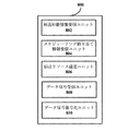
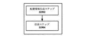
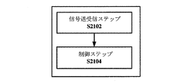
本開示のその他の一局面によれば、無線通信システムにおける方法をさらに提供し、当該方法は、無線通信システムにおける方法であって、D2D(Device to Device)通信を行うユーザー機器間の信号伝送の再送回数に関する情報を示す再送回数関連情報を含む、D2D通信を行うためのユーザー機器の配置情報を生成するための配置情報生成ステップと、生成された配置情報を、D2D通信を行うユーザー機器に伝送するための伝送ステップとを含む。 According to another aspect of the present disclosure, a method in a wireless communication system is further provided, the method being a method in a wireless communication system, for signal transmission between user devices performing D2D (Device to Device) communication. An arrangement information generation step for generating arrangement information of user equipment for performing D2D communication, including information related to the number of retransmissions indicating information on the number of retransmissions, and transmitting the generated arrangement information to the user equipment performing D2D communication A transmission step.
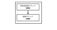
本開示のその他の一局面によれば、無線通信システムにおける方法をさらに提供し、当該方法は、D2D(Device to Device)通信を行うユーザー機器間信号伝送の再送回数に関する情報を示す再送回数関連情報を含む配置情報を受信するための信号送受信ステップと、受信された再送回数関連情報に応じて、前記信号送受信ステップで相手ユーザー機器へ信号を繰り返して伝送するように制御するための制御ステップとを含む。 According to another aspect of the present disclosure, a method in a wireless communication system is further provided, and the method includes information related to the number of retransmissions indicating information regarding the number of retransmissions of signal transmission between user devices that perform D2D (Device to Device) communication A signal transmission / reception step for receiving arrangement information including: a control step for controlling the signal transmission / reception step to repeatedly transmit a signal to a partner user device in accordance with the received retransmission count-related information. Including.
本開示のその他の一局面によれば、無線通信システムにおける方法をさらに提供し、当該方法は、D2D(Device to Device)通信を行うユーザー機器間の信号伝送の再送回数に関する情報を示す再送回数関連情報を含む配置情報を受信するための信号送受信ステップと、受信された再送回数関連情報に応じて前記信号送受信ステップで相手ユーザー機器から伝送する全ての信号を受信するように制御する制御ステップとを含む。 According to another aspect of the present disclosure, there is further provided a method in a wireless communication system, the method related to the number of retransmissions indicating information on the number of retransmissions of signal transmission between user devices performing D2D (Device to Device) communication. A signal transmission / reception step for receiving arrangement information including information, and a control step for controlling to receive all signals transmitted from the counterpart user equipment in the signal transmission / reception step according to the received retransmission count related information. Including.
本開示のその他の一局面によれば、記憶媒体をさらに提供し、当該記憶媒体は機器が読み取り可能なプログラムコードを含み、情報処理デバイスでプログラムコードを実行する場合、当該プログラムコードは、D2D(Device to Device)通信を行うユーザー機器間の信号伝送の再送回数に関する情報を示す再送回数関連情報を含むD2D通信を行うためのユーザー機器の配置情報を生成するための配置情報生成ステップと、生成された配置情報をD2D通信を行うユーザー機器に伝送するための伝送ステップとを含む方法を情報処理デバイスに実行させる。 According to another aspect of the present disclosure, a storage medium is further provided, and the storage medium includes a program code that can be read by a device, and when the information processing device executes the program code, the program code is D2D ( An arrangement information generation step for generating arrangement information of the user equipment for performing D2D communication including information related to the number of retransmissions indicating the number of retransmissions of signal transmission between user apparatuses that perform communication. The information processing device is caused to execute a method including a transmission step for transmitting the arrangement information to the user equipment that performs D2D communication.
本開示のその他の一局面によれば、記憶媒体をさらに提供し、当該記憶媒体は機器が読み取り可能なプログラムコードを含み、情報処理デバイスでプログラムコードを実行する場合、当該プログラムコードは、D2D(Device to Device)通信を行うユーザー機器間信号伝送の再送回数に関する情報を示す再送回数関連情報を含む配置情報を受信するための信号送受信ステップと、受信された再送回数関連情報に応じて、前記信号送受信ステップで相手ユーザー機器へ信号を繰り返して伝送するように制御するための制御ステップとを含む方法を情報処理デバイスに実行させる。 According to another aspect of the present disclosure, a storage medium is further provided, and the storage medium includes a program code that can be read by a device, and when the information processing device executes the program code, the program code is D2D ( Device to Device) a signal transmission / reception step for receiving arrangement information including information related to the number of retransmissions indicating information regarding the number of retransmissions of signal transmission between user devices that perform communication, and the signal according to the received information related to the number of retransmissions And causing the information processing device to execute a method including a control step for controlling to repeatedly transmit a signal to the partner user device in the transmission / reception step.
本開示のその他の一局面によれば、記憶媒体をさらに提供し、当該記憶媒体は機器が読み取り可能なプログラムコードを含み、情報処理デバイスでプログラムコードを実行する場合、当該プログラムコードは、D2D(Device to Device)通信を行うユーザー機器間の信号伝送の再送回数に関する情報を示す再送回数関連情報を含む配置情報を受信するための信号送受信ステップと、受信された再送回数関連情報に応じて前記信号送受信ステップで相手ユーザー機器から伝送される全ての信号を受信するように制御する制御ステップとを含む方法を情報処理デバイスに実行させる。 According to another aspect of the present disclosure, a storage medium is further provided, and the storage medium includes a program code that can be read by a device, and when the information processing device executes the program code, the program code is D2D ( (Device to Device) A signal transmission / reception step for receiving arrangement information including retransmission count related information indicating information related to the number of retransmissions of signal transmission between user devices performing communication, and the signal according to the received retransmission count related information And causing the information processing device to execute a method including a control step of controlling to receive all signals transmitted from the counterpart user device in the transmission / reception step.
本開示のその他の一局面によれば、プログラム製品をさらに提供し、当該プログラム製品は機器が実行可能な命令を含み、情報処理デバイスで命令を実行する場合、当該命令は、D2D(Device to Device)通信を行うユーザー機器間の信号伝送の再送回数に関する情報を示す再送回数関連情報を含むD2D通信を行うためのユーザー機器の配置情報を生成するための配置情報生成ステップと、生成された配置情報をD2D通信を行うユーザー機器に伝送するための伝送ステップとを含む方法を情報処理デバイスに実行させる。 According to another aspect of the present disclosure, a program product is further provided. The program product includes an instruction executable by the device. When the instruction is executed by the information processing device, the instruction is a D2D (Device to Device). ) An arrangement information generation step for generating arrangement information of user equipment for performing D2D communication including information related to the number of retransmissions indicating information on the number of retransmissions of signal transmission between user apparatuses performing communication, and the generated arrangement information The information processing device executes a method including a transmission step for transmitting to a user equipment that performs D2D communication.
本開示のその他の一局面によれば、プログラム製品をさらに提供し、当該プログラム製品は機器が実行可能な命令を含み、情報処理デバイスで命令を実行する場合、当該命令は、D2D(Device to Device)通信を行うユーザー機器間信号伝送の再送回数に関する情報を示す再送回数関連情報を含む配置情報を受信するための信号送受信ステップと、受信された再送回数関連情報に応じて、前記信号送受信ステップで相手ユーザー機器へ信号を繰り返して伝送するように制御するための制御ステップとを含む無線通信システムにおける方法を情報処理デバイスに実行させる。 According to another aspect of the present disclosure, a program product is further provided. The program product includes an instruction executable by the device. When the instruction is executed by the information processing device, the instruction is a D2D (Device to Device). ) A signal transmission / reception step for receiving arrangement information including information related to the number of retransmissions indicating information related to the number of retransmissions of signal transmission between user devices performing communication, and the signal transmission / reception step according to the received information related to the number of retransmissions. And causing an information processing device to execute a method in a wireless communication system including a control step for controlling to repeatedly transmit a signal to a counterpart user equipment.
本開示のその他の一局面によれば、プログラム製品をさらに提供し、当該プログラム製品は機器が実行可能な命令を含み、情報処理デバイスで命令を実行する場合、当該命令は、D2D(Device to Device)通信を行うユーザー機器間の信号伝送の再送回数に関する情報を示す再送回数関連情報を含む配置情報を受信するための信号送受信ステップと、受信された再送回数関連情報に応じて前記信号送受信ステップで相手ユーザー機器から伝送する全ての信号を受信するように制御する制御ステップとを含む方法を情報処理デバイスに実行させる。 According to another aspect of the present disclosure, a program product is further provided. The program product includes an instruction executable by the device. When the instruction is executed by the information processing device, the instruction is a D2D (Device to Device). ) A signal transmission / reception step for receiving arrangement information including retransmission number related information indicating information on the number of retransmissions of signal transmission between user devices performing communication, and the signal transmission / reception step according to the received retransmission number related information. And causing the information processing device to execute a method including a control step of controlling to receive all signals transmitted from the counterpart user equipment.
本開示のその他の一局面によれば、電子デバイスをさらに提供し、当該電子デバイスが無線通信システムに位置し、且つ、D2D(Device to Device)通信を行うユーザー機器間の信号伝送の再送回数に関する情報を示す再送回数関連情報を含むD2D(Device to Device)通信を行うためのユーザー機器の配置情報を生成するための配置情報生成ステップと、生成された配置情報をD2D(Device to Device)通信を行うユーザー機器に伝送するための伝送ステップとを含む方法を実行するように配置される回路を含む。 According to another aspect of the present disclosure, an electronic device is further provided, the electronic device is located in a wireless communication system, and the number of signal transmission retransmissions between user devices performing D2D (Device to Device) communication An arrangement information generation step for generating arrangement information of a user device for performing D2D (Device to Device) communication including information related to the number of retransmissions indicating information, and D2D (Device to Device) communication for the generated arrangement information. A circuit arranged to perform a method comprising: a transmission step for transmitting to a user equipment performing.
本開示のその他の一局面によれば、電子デバイスをさらに提供し、当該電子デバイスが無線通信システムに位置し、且つ、D2D(Device to Device)通信を行うユーザー機器間信号伝送の再送回数に関する情報を示す再送回数関連情報を含む配置情報を受信するための信号送受信ステップと、受信された再送回数関連情報に応じて、前記信号送受信ステップで相手ユーザー機器へ信号を繰り返して伝送するように制御するための制御ステップとを含む方法を実行するように配置される回路を含む。 According to another aspect of the present disclosure, an electronic device is further provided, the electronic device is located in a wireless communication system, and information regarding the number of retransmissions of signal transmission between user equipments that performs D2D (Device to Device) communication And a signal transmission / reception step for receiving arrangement information including retransmission number related information indicating that the signal is repeatedly transmitted to the counterpart user equipment in the signal transmission / reception step according to the received retransmission number related information. And a circuit arranged to carry out a method including a control step.
本開示のその他の一局面によれば、電子デバイスをさらに提供し、当該電子デバイスが無線通信システムに位置し、且つ、D2D(Device to Device)通信を行うユーザー機器間の信号伝送の再送回数に関する情報を示す再送回数関連情報を含む配置情報を受信するための信号送受信ステップと、受信された再送回数関連情報に応じて前記信号送受信ステップで相手ユーザー機器から伝送する全ての信号を受信するように制御する制御ステップとを含む方法を実行するように配置される回路を含む。 According to another aspect of the present disclosure, an electronic device is further provided, the electronic device is located in a wireless communication system, and the number of signal transmission retransmissions between user devices performing D2D (Device to Device) communication A signal transmission / reception step for receiving arrangement information including information related to the number of retransmissions indicating information, and all signals transmitted from the counterpart user equipment in the signal transmission / reception step according to the received information regarding the number of retransmissions A circuit arranged to carry out a method comprising a control step of controlling.
以下の明細書において本開示の実施例の他の方面を提供しているが、本開示の実施例を十分に開示するための好適な実施例を詳細に説明し、限定を意図するものでなはい。 Other aspects of the disclosed embodiments are provided in the following specification, but are not intended to be limiting and describe preferred embodiments in detail for fully disclosing the disclosed embodiments. Yes.
本開示は以下で図面に基づいて提供する詳細な記述を参考することでより良い理解を得ることができ、その中、全ての図面において、同一又は類似する符号を使用して同一又は類似する部品を示す。前記図面は以下の詳細説明とともに本明細書に含まれ明細書の一部を形成し、さらに例を上げて本開示の好適な実施例を説明し、及び本開示の原理と長所を解釈するためのものである。:
以下、図面に基づいて、本発明の例示的な実施例を記述する。明瞭かつ簡明のために、明細書において実際の実施形態の全部の特徴を記述しない。但し、理解すべきことは、開発者の具体的な目標を達成するために、いかなるのこれらの実際の実施例を開発する過程で実施形態に特定する決定をしなければならず、例えば、システム及び業務に関連する制限条件に適い、且つこれら制限条件は、実施形態が異なるに伴って変わる。加えて、理解すべきことは、開発仕事が複雑かつ時間が掛かるものであり得るが、本開示内容の利益を享受する当業者にとって、このような開発仕事はきまり通り行う任務に過ぎない。 Hereinafter, exemplary embodiments of the present invention will be described with reference to the drawings. For the sake of clarity and clarity, not all features of an actual embodiment are described in the specification. However, it should be understood that in the course of developing any of these actual implementations, decisions specific to the embodiment must be made in order to achieve the specific goals of the developer, for example, the system And, it is suitable for the restriction conditions related to business, and these restriction conditions change as the embodiments differ. In addition, it should be understood that development tasks can be complex and time consuming, but for those skilled in the art having the benefit of this disclosure, such development tasks are merely routine tasks.
ここで、さらに説明する必要がある点は、不必要な細部によって本開示をぼかすことを避けるために、図面において、少なくとも本発明の方案に緊密に関連するデバイス構成及び/又は処理ステップのみを示し、本発明に関係がない他の内容を省略した。 What needs to be further explained here is only the device configuration and / or processing steps that are at least closely related to the inventive approach in order to avoid blurring the present disclosure due to unnecessary details. Other contents not related to the present invention are omitted.
LTE−Aの標準化プロセスに応じて、現在、D2D発見メカニズムがType1と、Type2Aと、Type2Bとに分け、D2Dの通信メカニズムがそれぞれMode1、Mode2であると定義されたが、異なるD2Dメカニズムは、異なるリソース割り当て方式に係り、D2D通信に係るシグナリング設計、具体的に、伝送におけるリソーススケジューリング及びパラメータ配置に影響を与える。 According to the standardization process of LTE-A, D2D discovery mechanisms are currently divided into Type1, Type2A, and Type2B, and D2D communication mechanisms are defined as Mode1 and Mode2, respectively, but different D2D mechanisms are different. It affects the resource allocation method and affects the signaling design related to D2D communication, specifically, resource scheduling and parameter allocation in transmission.
以下、具体的に各種のD2D通信/発見メカニズムに対して以下の順序で本開示の実施例を記述する。 Hereinafter, embodiments of the present disclosure will be described in the following order specifically for various D2D communication / discovery mechanisms.
1.第1の実施例(D2D通信シングルセルシーンにおけるデータ信号伝送の方案設計について)
1-1. mode1通信モードでの方案設計
1-1-1. mode1通信モードでの基地局側/クラスタヘッド側の配置の一例
1-1-2. mode1通信モードでの伝送側ユーザー機器側の配置の一例
1-1-3. mode1通信モードでの受信側ユーザー機器側の配置の一例
1-2. mode2通信モードでの方案設計
1-2-1. mode2通信モードでの基地局側/クラスタヘッド側の配置の一例
1-2-2. mode2通信モードでの伝送側ユーザー機器側の配置の一例
1-2-3. mode2通信モードでの受信側ユーザー機器側の配置の一例
2.第2の実施例(D2D通信マルチセルシーンにおけるデータ信号伝送の方案設計について)
2-1. mode1通信モードでの方案設計
2-2. mode2通信モードでの方案設計
3.第3の実施例(D2D通信シングルセルシーンにおける発見信号伝送の方案設計について)
3-1. Type1発見メカニズムでの方案設計
3-1-1. Type1発見メカニズムでの基地局側/クラスタヘッド側の配置の一例
3-1-2. Type1発見メカニズムでの伝送側ユーザー機器側の配置の一例
3-1-3. Type1発見メカニズムでの受信側ユーザー機器側の配置の一例
3-2. Type2(Type2AとType2Bとを含む)発見メカニズムでの方案設計
3-2-1. Type2B発見メカニズムでの基地局側/クラスタヘッド側の配置の一例
3-2-2. Type2B発見メカニズムでのユーザー機器側の配置の一例
4.第4の実施例(D2D通信におけるスケジューリング割り当て情報伝送について)
5.応用実例
5-1.基地局の応用例について
5-2.ユーザー機器の応用例について
1. First embodiment (plan design of data signal transmission in D2D communication single cell scene)
1-1. Plan design in mode1 communication mode 1-1-1. Example of arrangement of base station side / cluster head side in mode1 communication mode 1-1-2. Transmission side user equipment side in mode1 communication mode Example of arrangement 1-1-3. Example of arrangement on the receiving-side user equipment side in
2-1. Design design in
3-1. Plan design with
5. Application examples
5-1. Application examples of base stations 5-2. Application examples of user equipment
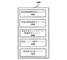
まず、図1を参照し、本開示の実施例による、無線通信システムにおける装置の機能構成の一例のブロック図を記述する。図1は、本開示の実施例による、無線通信システムにおける装置の機能構成の一例を示すブロック図である。 First, a block diagram of an example of a functional configuration of an apparatus in a wireless communication system according to an embodiment of the present disclosure will be described with reference to FIG. FIG. 1 is a block diagram illustrating an example of a functional configuration of an apparatus in a wireless communication system according to an embodiment of the present disclosure.
図1に示すように、装置100は配置情報生成ユニット102と伝送ユニット104とを含むことができる。
As shown in FIG. 1, the
配置情報生成ユニット102は、再送回数関連情報D2D通信を行うユーザー機器間の信号伝送の再送回数に関連する情報を示す再送回数関連情報を含むD2D通信を行うためのユーザー機器の配置情報を生成するように配置されることができる。
The arrangement
以上のように、D2D通信においてHARQフィードバックメカニズムが欠如し、本開示では、D2D通信伝送において信号伝送の正確な受信率を確保するために一定の数の再送を採用するように設計される。一例において、再送回数の設定はD2D信号の正確な受信率とリソース利用率に基づく。信号の正確な受信率が低いシーンにおいて(大きいネットワーク干渉又は高い端末モビリティ等が原因である可能性がある)、大きい再送回数を設置する。具体的に、例えばネットワークにおけるユーザー機器がチャネル品質に対する測定レポートを収集することで信号の正確な受信率を確定してもよい。リソースが不足するシーン(例えばD2D通信を行うユーザー機器の数が大きい/位置分布が集中する)において、小さい再送回数を設置して同じ信号を伝送して使用する必要があるリソースを低減してもよい。 As described above, HARQ feedback mechanism is lacking in D2D communication, and the present disclosure is designed to employ a certain number of retransmissions in order to ensure an accurate reception rate of signal transmission in D2D communication transmission. In one example, the setting of the number of retransmissions is based on an accurate reception rate and resource utilization rate of the D2D signal. In scenes where the signal reception rate is low (possibly due to large network interference or high terminal mobility), a large number of retransmissions is installed. Specifically, for example, the user equipment in the network may collect a measurement report on channel quality to determine an accurate signal reception rate. Even in a scene where resources are scarce (for example, the number of user devices performing D2D communication is large / positional distribution is concentrated), it is possible to reduce resources that need to be transmitted and used by setting a small number of retransmissions. Good.
伝送ユニット104は、生成した配置情報を、D2D(Device to Device)通信を行うユーザー機器に伝送するように配置されることができる。
The
なお、ここの配置情報生成ユニット102は基地局側、D2D通信における例えばD2Dクラスタヘッド(cluster head)側又はD2D信号のユーザー機器側に設置されてもよい。ユーザー機器側に設置された場合に、各ユーザー機器が現在の通信状況に応じて再送回数関連情報を設定し、そして、伝送ユニット104が再送回数関連情報が含まれる配置情報をスケジューリング割り当て(SA,Scheduling Assignment)情報に含ませ装置100とD2D通信を行う相手ユーザー機器に当該再送回数関連情報を通知する。この場合、各ユーザー機器により設定された再送回数が異なってもよい。
The arrangement
以下、配置情報生成ユニット102が基地局側又はクラスタヘッド側に設置された場合についてD2D通信における前記各シーンに適する方案設計を詳細に記述する。理解すべきことは、この場合、各ユーザー機器に用いられる再送回数が同じである。
Hereinafter, a plan design suitable for each scene in the D2D communication when the arrangement
<1.第1の実施例>
[1-1.mode1通信モードでの方案設計]
図2ないし図8を参考して本開示の第1の実施例による、D2D通信シングルセルシーンのmode1通信モードでのデータ信号伝送に対する方案設計を記述する。D2D通信のmode1通信モードにおいて、通信リソースが集中により、例えば一つの集中するデバイス(例えば、基地局、クラウドBB(Cloud BaseBand) 又はクラスタヘッド)により割り当てられる。
<1. First embodiment>
[1-1. Plan design in
A method design for data signal transmission in the
以上のように、本開示では、D2D通信伝送において一定の数の再送を採用して正確な受信率を向上させるように設計され、加えて、本開示の発明者は、再送する度に前回の伝送と異なる伝送リソース、例えば異なる周波数のリソースを採用して、周波数ダイバシティ利得を十分に利用し、全体としてさらにD2D通信情報の正確な受信率を向上させるということが提案された。本開示において、前記した再送する度に前回の伝送と異なる周波数リソースを採用する具体的リソースマッピングメカニズムを簡単に周波数ホッピングと称することがある。 As described above, the present disclosure is designed to improve the accurate reception rate by adopting a certain number of retransmissions in D2D communication transmission. In addition, the inventor of the present disclosure can It has been proposed to employ transmission resources different from transmission, for example, resources of different frequencies, to fully utilize the frequency diversity gain and further improve the accurate reception rate of D2D communication information as a whole. In the present disclosure, a specific resource mapping mechanism that employs a frequency resource different from the previous transmission every time it is retransmitted may be simply referred to as frequency hopping.
注意すべきなのは、従来技術において、基地局がユーザー機器のアップリンク伝送要求に対してリソーススケジューリングを逐次行い、ユーザー機器にアップリンクリソースを割り当てる度に、仮想リソースブロック(Virtual Resource Block:VRB)の形式でユーザー機器に今回の伝送において利用可能なアップリンクリソースを指示し、ユーザー機器がVRBに応じて利用可能な物理リソースブロック(Physical Resource Block:PRB)を確定し、言い換えれば,VRBをPRBにマッピングしてからPRBを利用して実際のアップリンク伝送を行う。なお、基地局の例えば周波数ホッピングフラグ(hopping flag)に基づく指示、PRBは、VRBに直接に一対一対応してもよく、まずVRBにインターリーブを行ってから一定のルールに従ってリソースが不連続であるPRBにマッピングしてもよく、後者の場合について、VRBからPRBへのマッピング過程で周波数ホッピング技術を応用したとも考えられ、その具体的形態が3GPP LTE−A規格の記述を参考してもよく、ここで重複しない。従って、本開示の幾つかの例において二回の周波数ホッピング処理を含み、リソース集中割り当てデバイスから得られるVRBからPRBまでの伝統の周波数ホッピング(同一回伝送リソースに対して)、及び前回の伝送リソースから次回の伝送リソースまでの周波数ホッピング(PRBからPRBまでであってもよい)である。以下開示される周波数ホッピング方案設計は、主に前回の上次伝送リソースから次回の伝送リソースへのマッピングに対して、例えば初回の伝送から一回目の伝送リソースへのマッピング、一回目の伝送リソースから二回目の伝送リソースへのマッピング等である。 It should be noted that in the prior art, the base station sequentially performs resource scheduling in response to the uplink transmission request of the user equipment, and assigns an uplink resource to the user equipment, so that a virtual resource block (VRB) The user equipment is instructed in the form of the uplink resources that can be used in the current transmission, and the user equipment determines the physical resource block (PRB) that can be used according to the VRB. In other words, the VRB is changed to the PRB. After mapping, actual uplink transmission is performed using PRB. In addition, an instruction based on a frequency hopping flag (hopping flag) of the base station, PRB may directly correspond to VRB, and resources are discontinuous according to certain rules after interleaving VRB first. It may be mapped to PRB, and in the latter case, it is considered that frequency hopping technology is applied in the mapping process from VRB to PRB, and the specific form may refer to the description of 3GPP LTE-A standard, Don't overlap here. Thus, in some examples of the present disclosure, including frequency hopping twice, traditional frequency hopping (from the same transmission resource) from VRB to PRB obtained from the resource intensive allocation device, and the previous transmission resource Frequency hopping from one to the next transmission resource (may be from PRB to PRB). The frequency hopping scheme design disclosed below is mainly based on the mapping from the previous upper transmission resource to the next transmission resource, for example, mapping from the first transmission to the first transmission resource, and from the first transmission resource. For example, mapping to the second transmission resource.
以下、mode 1の場合の周波数ホッピング方案設計の好適な例を提供し、しかしながら理解すべきことは、例示に過ぎず限定されるものではなく、当業者は本開示の周波数ホッピング方案設計の原則に応じて他の方案を想到することができる。
The following provides a preferred example of frequency hopping scheme design for
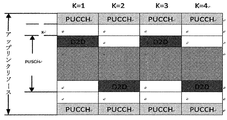
方案1:D2D通信のためのデータ信号伝送のリソースをアップリンク帯域リソース全体のエッジに分布させ物理アップリンク制御チャンネル(PUCCH)に近づけるとともに、隣り合う伝送リソース間の周波数スパンをできるだけ大きくさせる。 Method 1: Resource for data signal transmission for D2D communication is distributed at the edge of the entire uplink band resource so as to be close to the physical uplink control channel (PUCCH), and the frequency span between adjacent transmission resources is made as large as possible.
図2は方案1によるデータ信号伝送リソースの分布模式図を示す。図2に示すように、D2D通信のための周波数リソースがPUCCHに近づくとともに、隣り合う伝送リソースが上下周波数ホッピングの原則に従って分布することで、近接して二回伝送する伝送リソース間の周波数のスパンを最大化させる。本開示はD2D通信の周波数リソースをできるだけPUCCHに近づけるように設計することにより、周波数スパンを最大化させることを除いて、連続するPUSCHリソースを事前残して基地局と通信する伝統のユーザー機器にリソースを割り当てることが可能である。また、図2に示す一例において、D2D通信のための周波数リソースとPUCCHとの間隔XはPUCCHに干渉することを避けるために設置される保護間隔であり、例えば1に一律に設置されてもよく、又は基地局或いはクラスタヘッドとの距離に応じて設置されてもよい。例えば、基地局又はクラスタヘッドに近接すると、大きい値に設定されてもよく、逆に、小さい値に設置されるかゼロに設置されてもよい。
FIG. 2 is a schematic diagram of data signal transmission resource distribution according to
以下、方案1におけるデータ伝送リソースの確定のアルゴリズムの一例を提供する。仮に初送するデータが占める周波数リソースインデックスがfとすると、当該インデックスがリソースブロック(RB)のシリアルナンバーに対応する。まず、それをアップリンク伝送帯域のうちPUCCH寄りのD2Dデータ領域にマッピングし、f(0)と記載される。
In the following, an example of an algorithm for determining data transmission resources in
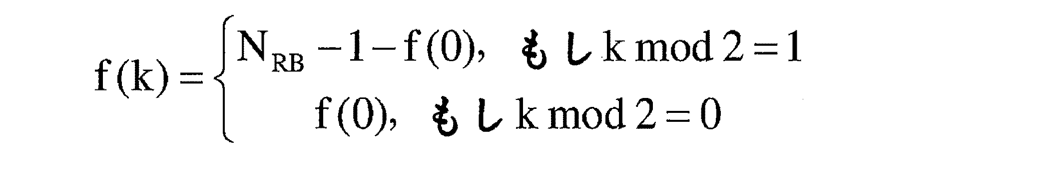
後続の再送リソースの周波数リソースインデックスがf(k)となり、k={1、2、…、K−1}であり、Kが再送回数である。 The frequency resource index of the subsequent retransmission resource is f (k), k = {1, 2,..., K−1}, and K is the number of retransmissions.
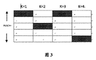
方案2:隣り合う伝送リソースの周波数スパンをできるだけ大きくさせ、伝送リソース全体の分布がランダムとなるようにさせ、周波数ホッピング配置の柔軟性を確保させる。 Method 2: The frequency span of adjacent transmission resources is increased as much as possible, the distribution of the entire transmission resources is made random, and the flexibility of frequency hopping arrangement is ensured.
図3は方案2によるデータ信号伝送リソースの分布模式図を示す。図3に示すように、サブ帯域の数の整数倍を、隣接して二回伝送する伝送リソース間の周波数間隔とするとともに、伝送リソース全体の分布がランダムに分布する。
FIG. 3 is a schematic diagram of data signal transmission resource distribution according to
以下、方案2におけるデータ伝送リソースの確定のアルゴリズムの一例を提供する。仮に初回伝送するデータが占める周波数リソースインデックスがfとすると、まず、既存の物理アップリンク共有チャネル(PUSCH)の周波数ホッピングのマッピング原則に従ってそれを対応するアップリンク伝送リソースとしてマッピングしてもよく、f(0)と記載され、後続の再送リソースの周波数リソースインデックスがf(k)となり、k={1、2、…、K}であり、Kが再送回数である。
In the following, an example of an algorithm for determining data transmission resources in
![]()
![]()
以上の記述から、本開示の実施例による周波数ホッピング方案設計において、D2D通信について、二回の周波数ホッピング設計を含み、即ち周波数ホッピングと再送周波数ホッピングを含むことが分かる。以上開示されたアルゴリズムの一例において初送リソース周波数インデックスfから実際の初送リソースf(0)へのマッピングが初送周波数ホッピングであり、k−1回目の伝送リソースf(k−1)からk回目の伝送リソースf(k)へのマッピングが再送周波数ホッピングである。理解すべきことは、実際の応用において必要に応じて初送周波数ホッピングのみを応用してもよく、この際、再送リソースと初送リソースとは位置が同じであるので、複数回伝送する周波数ダイバシティ利得を利用することを考慮しない。 From the above description, it can be seen that the frequency hopping scheme design according to the embodiment of the present disclosure includes two frequency hopping designs for D2D communication, that is, frequency hopping and retransmission frequency hopping. In the example of the algorithm disclosed above, the mapping from the initial transmission resource frequency index f to the actual initial transmission resource f (0) is the initial transmission frequency hopping, and the k−1th transmission resource f (k−1) to k The second mapping to transmission resource f (k) is retransmission frequency hopping. It should be understood that only the initial transmission frequency hopping may be applied as necessary in an actual application. In this case, since the retransmission resource and the initial transmission resource have the same position, the frequency diversity to be transmitted multiple times is used. Don't consider using gain.
[1-1-1. mode1通信モードでの基地局側/クラスタヘッド側の配置の一例]
次に、図4を参考してmode1通信モードでの基地局側/クラスタヘッド側の装置の機能構成の一例を詳細に記述する。図4は本開示の第1の実施例によるmode1通信モードでの基地局側/クラスタヘッド側の装置の機能構成の一例を示すブロック図である。
[1-1-1. Example of arrangement on base station side / cluster head side in
Next, an example of the functional configuration of the base station side / cluster head side apparatus in the
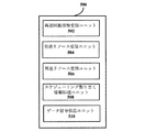
図4に示すように、装置400は、配置情報生成ユニット402と、システム情報生成ユニット404と、リソーススケジューラ406と、リソース割り当て情報生成ユニット408と、伝送ユニット410とを含んでいる。ここの配置情報生成ユニット402と伝送ユニット410との機能構成の一例は以上の図1を参考して記述された配置情報生成ユニット102と伝送ユニット104との機能構成の一例と同じであるので、ここで重複して記述しない。次にシステム情報生成ユニット404と、リソーススケジューラ406と、リソース割り当て情報生成ユニット408との機能構成の一例のみを詳細に記述する。
As shown in FIG. 4, the
システム情報生成ユニット404は、配置情報生成ユニット402が生成する配置情報をシステム情報ブロック(SIB)に含むように配置される。
The system
伝送ユニット410は、当該システム情報ブロックをD2D通信を行うユーザー機器に送信するように配置されることができる。理解すべきことは、基地局側/クラスタヘッド側により再送回数関連情報が生成される場合に、各ユーザー機器のための再送回数関連情報が一般に同じであるので、伝送ユニットは好ましくは、ブロードキャストの方式により、例えばブロードキャスト制御チャネル(BCCH)を介してシステム情報ブロックを送信して、情報伝送量を減少する。しかしながら、ここで、例えば専用のシグナリングにより再送回数関連情報を伝送することにより、各ユーザー機器について異なる再送回数を配置することが可能となることを排除しない。
The
リソーススケジューラ406は、D2D通信を行うためのユーザー機器間の信号伝送の伝送リソースを割り当てるように配置されることができる。ここのリソーススケジューラが例えばMACレイヤのうちアップリンク共有チャネルリソースをスケジューリングするためのスケジューラ(scheduler)に対応する。以上のように、好ましくは、リソーススケジューラ406は周波数がPUCCHに近づくリソースを、D2D通信を行うためのユーザー機器に割り当てるように配置されてもよい。また、リソーススケジューラ406は例えばユーザー機器から基地局又はクラスタヘッドまでの距離に応じてD2D通信を行うための伝送リソースとPUCCHとの近接程度を確定してもよい。
The
リソース割り当て情報生成ユニット408は、伝送リソースの指示情報を含むダウンリンク制御情報(DCI)又はランダムアクセス応答情報を生成するように配置されることができる。伝送ユニット410は、PDCCHにより当該DCI又はランダムアクセス応答情報をD2D通信における伝送側ユーザー機器に送信してD2D通信を行うための伝送リソースを指示することが可能である。ここの伝送リソースの指示情報は、例えばDCIフォーマット0によりロードされるアップリンクスケジューリンググラント(UL−grant)情報に対応するとともに、一つの特殊の無線ネットワーク一時識別子(RNTI)を使用してこのUL−grantがD2D通信を行うためのものであることを表し、セルラー通信UL−grantと区別する。また、ランダムアクセス応答情報はDCIフォーマット1Cを使用することによりPDCCHを介して伝送されてもよい。
Resource allocation information generation unit 408 may be arranged to generate downlink control information (DCI) or random access response information including transmission resource indication information. The
当該伝送リソースは、少なくともD2D通信を行うためのユーザー機器の信号が初送する初送リソースを含む。好ましくは、当該伝送リソースはD2D通信における信号再送を行うための再送リソースを含んでもよく、この際、基地局又はクラスタヘッドにより再送リソースを確定して、ユーザー機器に初送リソースと再送リソースとを明示的に指示する。具体的に、基地局又はクラスタヘッドは初送リソースの位置に応じて再送リソースの位置を確定してもよい。信号再送に周波数ホッピング技術を応用する場合に、例えば前記周波数ホッピング方案を採用して再送リソースを確定してもよい。 The transmission resource includes at least an initial transmission resource for initial transmission of a signal of a user equipment for performing D2D communication. Preferably, the transmission resource may include a retransmission resource for performing signal retransmission in D2D communication. At this time, the retransmission resource is determined by the base station or the cluster head, and the initial transmission resource and the retransmission resource are allocated to the user equipment. Explicitly instruct. Specifically, the base station or cluster head may determine the position of the retransmission resource according to the position of the initial transmission resource. When frequency hopping technology is applied to signal retransmission, for example, the frequency hopping scheme may be adopted to determine retransmission resources.
代わりに、基地局側が初送リソースのみを割り当て、ユーザー機器側により予定の周波数ホッピング方案に応じて後続の再送リソースが確定されることもある。この場合、好ましくは、配置情報生成ユニット402はさらにD2D通信における信号再送に周波数ホッピング技術を応用するかを指示する再送周波数ホッピング指示識別子を、配置情報に含ませて送信ユニット410を介してユーザー機器に送信するように配置されてもよく、そして、ユーザー機器は受信した再送周波数ホッピング指示識別子と初送リソースとに応じて、予定の周波数ホッピング方案を採用して後続の再送リソースを確定してもよい。好ましくは、当該再送周波数ホッピング指示識別子がシステム情報ブロックに含まれ、且つ送信ユニット410を介してD2D通信を行う全てのユーザー機器にブロードキャストされ、各ユーザー機器が信号伝送と受信を行う相応リソース位置を確定してもよい。
Instead, the base station side may allocate only the initial transmission resource, and the user equipment side may determine subsequent retransmission resources according to a scheduled frequency hopping scheme. In this case, preferably, the arrangement
また、代わりに、リソーススケジューラ406は、信号再送に周波数ホッピング技術を応用するか否かを確定してD2D通信を行うための伝送リソースを割り当てる(初送リソースと再送リソースとを含む)ように配置されてもよい。この際、伝送ユニット410は、再送周波数ホッピング指示識別子を含む伝送リソースの指示情報をDCI又はランダムアクセス応答情報に含ませてD2D通信における伝送側ユーザー機器に送信してもよい。この例において、伝送ユニット410は、同時に再送周波数ホッピング指示識別子と初送周波数ホッピング指示識別子とをDCI又はランダムアクセス応答情報に含ませてD2D通信における伝送側ユーザー機器に送信してもよい。
Instead, the
また、代わりに、基地局側が初送リソースの割り当てのみを担うが後続の再送を担わなくてもよく、即ち、ユーザー機器自身が再送に周波数ホッピング技術を応用するか否か及びどのように再送リソースを割り当てるかを決定する。 Alternatively, the base station side is only responsible for allocation of initial transmission resources but may not be responsible for subsequent retransmissions, i.e., whether the user equipment itself applies frequency hopping technology for retransmissions and how to retransmit resources. Decide whether to assign
理解すべきことは、再送に周波数ホッピング技術を応用すると確定された場合に、各再送リソースと前回伝送リソースとの間の周波数が少なくとも異なり、例えば、各再送リソースと前回伝送リソースとの間の周波数スパンが予定条件、例えば、周波数スパンが最大化する又はサブ帯域の数の整数倍であることを満足する。具体的に、例えば、以上の図2又は図3を参考して記述された周波数ホッピング方案に応じて再送リソースを確定してもよい。なお、本開示の幾つかの実施例において、再送周波数ホッピング技術を応用するか否かを指示しない場合に、デフォルトで再送周波数ホッピングを実行する。 It should be understood that when it is determined that the frequency hopping technique is applied to retransmission, the frequency between each retransmission resource and the previous transmission resource is at least different, for example, the frequency between each retransmission resource and the previous transmission resource. Satisfy that the span is a predetermined condition, eg, the frequency span is maximized or is an integer multiple of the number of sub-bands. Specifically, for example, the retransmission resource may be determined according to the frequency hopping scheme described with reference to FIG. 2 or FIG. Note that, in some embodiments of the present disclosure, retransmission frequency hopping is executed as a default when not instructing whether to apply the retransmission frequency hopping technique.
[1-1-2. mode1通信モードでの伝送側ユーザー機器側の配置の一例]
次に、図5ないし図7を参考してmode1通信モードでの伝送側ユーザー機器側の装置の機能構成の一例を詳細に記述する。
[1-1-2. Example of arrangement on transmission side user equipment in mode1 communication mode]
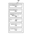
Next, an example of the functional configuration of the device on the transmission-side user device side in the
図5は本開示の第1の実施例によるmode1通信モードでの伝送側ユーザー機器側の装置の機能構成の一例を示すブロック図である。
FIG. 5 is a block diagram illustrating an example of a functional configuration of an apparatus on the transmission-side user device side in the
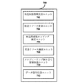
図5に示すように、装置500は、再送回数情報受信ユニット502と、初送リソース受信ユニット504と、再送リソース受信ユニット506と、スケジューリング割り当て情報伝送ユニット508と、データ信号伝送ユニット510とを含んでいる。
As shown in FIG. 5,
再送回数情報受信ユニット502は、D2D通信を行うユーザー機器間に再送を行うための回数を示す再送回数情報を受信するように配置されることができる。 The retransmission number information receiving unit 502 can be arranged to receive retransmission number information indicating the number of times for performing retransmission between user devices that perform D2D communication.
初送リソース受信ユニット504は、D2D通信におけるデータ信号が初送するための初送リソースを指示する初送リソース指示を受信するように配置されることができる。
The initial transmission
再送リソース受信ユニット506は、D2D通信におけるデータ信号が再送するための再送リソースを指示する再送リソース指示を受信するように配置されることができる。
Retransmission
スケジューリング割り当て情報伝送ユニット508は、初送リソース指示と再送リソース指示とをスケジューリング割り当て情報に含ませて相手ユーザー機器に送信するように配置されることができる。 The scheduling assignment information transmission unit 508 can be arranged to include the initial transmission resource instruction and the retransmission resource instruction in the scheduling assignment information and transmit it to the counterpart user equipment.
データ信号伝送ユニット510は、受信された再送回数情報に応じて、初送リソース指示と再送リソース指示が指示する伝送リソース上に相手ユーザー機器へデータ信号を繰り返して送信するように配置されることができる。
The data signal
なお、本開示の幾つかの例における装置組立ユニットは一定の論理機能に従って区分されたが、しかしながら理解すべきことは、その中の複数のユニットの機能が一つのモジュールにより実現されてもよく、一つのユニットの機能が複数のモジュールにより連携して実現されてもよく、例えば、前記の再送回数情報受信ユニット502と、初送リソース受信ユニット504と、再送リソース受信ユニット506と、データ信号伝送ユニット510とがいずれも例えば信号送受信ユニットにより実現されてもよく、そして、スケジューリング割り当て情報伝送ユニット508が例えば制御ユニットと信号送受信ユニットとにより実現されてもよい。具体的な信号送受信ユニットと制御ユニットが端末製品における例えば無線通信インタフェース、プロセッサ等の素子の配置により実現されてもよい。
It should be noted that the device assembly units in some examples of the present disclosure are partitioned according to certain logic functions, however, it should be understood that the functions of multiple units within them may be realized by a single module, The function of one unit may be realized in cooperation with a plurality of modules. For example, the retransmission number information reception unit 502, the initial transmission
図5に示す例において、伝送側ユーザー機器は直接に基地局側/クラスタヘッド側から初送リソースと再送リソースとについての明確な指示を受信し、自己が予定の周波数ホッピングアルゴリズムを再利用して相応する初送と再送リソースとを推計する必要がないことが分かる。 In the example shown in FIG. 5, the transmission-side user equipment receives clear instructions about the initial transmission resource and the retransmission resource directly from the base station side / cluster head side, and reuses the scheduled frequency hopping algorithm by itself. It can be seen that there is no need to estimate the corresponding initial transmission and retransmission resources.
図6は本開示の第1の実施例によるmode1通信モードでの伝送側ユーザー機器側の装置の他の一機能構成の一例を示すブロック図である。
FIG. 6 is a block diagram illustrating an example of another functional configuration of the apparatus on the transmission-side user device side in the
図6に示すように、装置600は、再送回数情報受信ユニット602と、初送リソース受信ユニット604と、再送周波数ホッピング指示識別子受信ユニット606と、再送リソース確定ユニット608と、スケジューリング割り当て情報伝送ユニット610と、データ信号伝送ユニット612とを含むことができる。なお、再送回数情報受信ユニット602と、初送リソース受信ユニット604と、データ信号伝送ユニット612との機能構成の一例は図5に示す再送回数情報受信ユニット502と、初送リソース受信ユニット504と、データ信号伝送ユニット510との機能構成の一例と同じであるので、ここで重複して記述しない。以下再送周波数ホッピング指示識別子受信ユニット606と、再送リソース確定ユニット608と、スケジューリング割り当て情報伝送ユニット610との機能構成の一例のみを詳細に記述する。
As shown in FIG. 6,
再送周波数ホッピング指示識別子受信ユニット606は、D2D通信におけるデータ信号再送に周波数ホッピング技術を応用するか否かを指示する再送周波数ホッピング指示識別子を受信するように配置されることができる。 Retransmission frequency hopping instruction identifier receiving unit 606 can be arranged to receive a retransmission frequency hopping instruction identifier that indicates whether to apply frequency hopping technology to data signal retransmission in D2D communication.
再送リソース確定ユニット608は、初送リソース指示と再送周波数ホッピング指示識別子とに基づいてD2D通信におけるデータ信号再送のための再送リソースを指示する再送リソース指示を確定するように配置されることができる。好ましくは、再送リソース確定ユニット608は、初送リソース指示、再送周波数ホッピング指示識別子、及び予定のジャンプ関数に基づいて再送リソースを確定してもよい。当該予定のジャンプ関数は、各再送リソースと前回伝送リソースとの間に跨る帯域幅を確定する周波数ホッピングパラメータを含んでもよい。当該周波数ホッピングパラメータは例えば装置600により確定されてもよい。
The retransmission
スケジューリング割り当て情報伝送ユニット610は、少なくとも初送リソース指示をスケジューリング割り当て情報に含ませて相手ユーザー機器に伝送し、相手ユーザー機器に初送リソースと再送リソースを確定させるように配置される。好ましくは、スケジューリング割り当て情報伝送ユニット610は、周波数ホッピングパラメータをスケジューリング割り当て情報に含ませて相手ユーザー機器に再送リソースを確定させてもよい。代わりに、スケジューリング割り当て情報伝送ユニット610は、再送リソースを指示する再送リソース指示をスケジューリング割り当て情報に明示的に含ませて相手ユーザー機器に伝送するように配置されてもよい。
The scheduling assignment
なお、以上のように、ここの再送回数情報受信ユニット602と、初送リソース受信ユニット604と、再送周波数ホッピング指示識別子受信ユニット606と、データ信号伝送ユニット612とがいずれも例えば信号送受信ユニットにより実現されてもよく、スケジューリング割り当て情報伝送ユニット610が例えば制御ユニットと信号送受信ユニットとにより実現されてもよく、そして、再送リソース確定ユニット608が例えば制御ユニットにより実現されてもよい。具体的な信号送受信ユニットと制御ユニットとが端末製品における例えば無線通信インタフェース、プロセッサ等の素子の配置により実現されてもよい。
As described above, the retransmission number information reception unit 602, the initial transmission
図6に示す例において、伝送側ユーザー機器は基地局側/クラスタヘッド側からの再送周波数ホッピング指示識別子に応じて、初送リソース指示と予定の周波数ホッピング方案に基づいてデータ信号再送のための再送リソースを確定し、図5に示す例と同様に直接に基地局/クラスタヘッドから割り当てられた再送リソースを受信しないことが分かる。この場合、受信側ユーザー機器は予定のジャンプ関数に応じて自分で再送リソースを確定するか、又は直接に伝送側ユーザー機器から再送リソースを受信してもよい。 In the example shown in FIG. 6, the transmission-side user equipment performs retransmission for data signal retransmission based on the initial transmission resource instruction and the planned frequency hopping scheme in accordance with the retransmission frequency hopping instruction identifier from the base station side / cluster head side. It can be seen that the resource is determined and the retransmission resource allocated directly from the base station / cluster head is not received as in the example shown in FIG. In this case, the reception-side user device may determine the retransmission resource by itself according to a scheduled jump function, or may directly receive the retransmission resource from the transmission-side user device.
図7は本開示の第1の実施例によるmode1通信モードでの伝送側ユーザー機器側の装置の他の一機能構成の一例を示すブロック図である。
FIG. 7 is a block diagram illustrating an example of another functional configuration of the device on the transmission-side user device side in the
図7に示すように、装置700は、再送回数情報受信ユニット702と、初送リソース受信ユニット704と、再送周波数ホッピング確定ユニット706と、再送リソース確定ユニット708と、スケジューリング割り当て情報伝送ユニット710と、データ信号伝送ユニット712とを含むことができる。なお、再送回数情報受信ユニット702と、初送リソース受信ユニット704と、データ信号伝送ユニット712との機能構成の一例は図6に示す再送回数情報受信ユニット602と、初送リソース受信ユニット604と、データ信号伝送ユニット612との機能構成の一例と同じであるので、ここで重複して記述しない。以下再送周波数ホッピング確定ユニット706と、再送リソース確定ユニット708と、スケジューリング割り当て情報伝送ユニット710との機能構成の一例のみを詳細に記述する。
As shown in FIG. 7,
再送周波数ホッピング確定ユニット706は、D2D通信におけるデータ信号再送に周波数ホッピング技術を応用するか否かを確定するように配置されることができる。
The retransmission frequency hopping
再送リソース確定ユニット708は、初送リソース指示と再送周波数ホッピング確定ユニット706の確定結果とに基づいて再送リソースを確定するように配置されることができる。
The retransmission
また、好ましくは、再送周波数ホッピング確定ユニット706は、D2D通信におけるデータ信号再送に周波数ホッピング技術を応用するか否かを指示する再送周波数ホッピング指示識別子を生成するように配置されてもよい。この際、再送リソース確定ユニット708は、初送リソース指示と再送周波数ホッピング確定ユニット706の再送周波数ホッピング決定とに基づいて再送リソースを確定するように配置されてもよい。
Also preferably, the retransmission frequency hopping
スケジューリング割り当て情報伝送ユニット710は、少なくとも初送リソース指示と再送周波数ホッピング指示識別子とをスケジューリング割り当て情報に含ませて相手ユーザー機器に伝送し、相手ユーザー機器に初送リソースと再送リソースとを確定させるように配置されてもよい。また、好ましくは、スケジューリング割り当て情報伝送ユニット710は、再送リソースを指示する再送リソース指示をスケジューリング割り当て情報に含ませて相手ユーザー機器に伝送してもよく、この際再送周波数ホッピング指示識別子を伝送する必要がない。 The scheduling assignment information transmission unit 710 includes at least an initial transmission resource instruction and a retransmission frequency hopping instruction identifier in the scheduling assignment information and transmits them to the counterpart user equipment so that the counterpart user equipment determines the initial transmission resource and the retransmission resource. May be arranged. In addition, preferably, the scheduling assignment information transmission unit 710 may transmit a retransmission resource instruction indicating the retransmission resource to the counterpart user equipment by including the retransmission resource instruction in the scheduling assignment information, and at this time, it is necessary to transmit the retransmission frequency hopping instruction identifier. There is no.
なお、以上のように、ここの再送回数情報受信ユニット702と、初送リソース受信ユニット704と、データ信号伝送ユニット712とがいずれも例えば信号送受信ユニットにより実現されてもよく、スケジューリング割り当て情報伝送ユニット710が例えば制御ユニットと信号送受信ユニットとにより実現されてもよく、そして、再送周波数ホッピング確定ユニット706と再送リソース確定ユニット708とが例えば制御ユニットにより実現されてもよい。具体的な信号送受信ユニットと制御ユニットとが端末製品における例えば無線通信インタフェース、プロセッサ等の素子の配置により実現されてもよい。
As described above, the retransmission number information receiving unit 702, the initial transmission
図7に示す例において、基地局側/クラスタヘッド側は初送リソースを指示することのみを担うが後続の再送を担わなく、そして伝送側ユーザー機器は自分で再送に周波数ホッピング技術を応用するか否かを確定し且つ後続の再送リソースを算出する。 In the example shown in FIG. 7, the base station side / cluster head side is only responsible for instructing the initial transmission resource, but does not take subsequent retransmissions, and does the transmission side user equipment apply frequency hopping technology for retransmission on its own? Determine whether or not and calculate subsequent retransmission resources.
理解すべきことは、前記でデータ信号再送に周波数ホッピング技術を応用すると確定された場合に、各再送リソースと前回伝送リソースとの間の周波数が少なくとも異なる。 It should be understood that when it is determined that the frequency hopping technique is applied to data signal retransmission as described above, the frequency between each retransmission resource and the previous transmission resource is at least different.
また、さらに理解すべきことは、デフォルトで再送に周波数ホッピングを応用する場合に、前記再送周波数ホッピングに関するユニット、例えば、再送周波数ホッピング指示識別子受信ユニット、再送周波数ホッピング確定ユニット等が設置されなくてもよい。 Further, it should be understood that when frequency hopping is applied to retransmission by default, a unit related to the retransmission frequency hopping, for example, a retransmission frequency hopping instruction identifier receiving unit, a retransmission frequency hopping determination unit, etc. may not be installed. Good.
ここで、なお、受信された初送リソースは、既にアップリンク伝送帯域のうちD2D通信のための領域にマッピングした周波数リソースインデックスであってもよく、又はマッピングする前の周波数リソースインデックスであってもよい。この際、伝送側ユーザー機器側は、相応する、初送リソース指示をアップリンク伝送帯域のうちD2D通信のための相応領域にマッピングするための初送リソースマッピングユニットをさらに設置する必要がある。 Here, the received initial transmission resource may be a frequency resource index that has already been mapped to an area for D2D communication in the uplink transmission band, or may be a frequency resource index before mapping. Good. At this time, the transmission side user equipment side needs to further install a corresponding initial transmission resource mapping unit for mapping an initial transmission resource instruction to a corresponding area for D2D communication in the uplink transmission band.
また、以前記述された装置500、600、700は、符号化ユニットをさらに含んでもよく、送信される情報を符号化し、データ信号伝送ユニットにより受信側ユーザー機器側に送信され、具体的な符号化方式が伝統のPUSCHデータの符号化方式と同じであってもよく、ここで重複しない。
Also, the previously described
<1-1-3. mode1通信モードでの受信側ユーザー機器側の配置の一例>
次に、図8を参考して本開示の第1の実施例によるmode1通信モードでの受信側ユーザー機器側の装置の機能構成の一例を記述する。図8は本開示の第1の実施例によるmode1通信モードでの受信側ユーザー機器側の装置の機能構成の一例を示すブロック図である。
<1-1-3. An example of arrangement on the receiving-side user equipment side in
Next, an example of a functional configuration of the device on the reception-side user device side in the mode1 communication mode according to the first embodiment of the present disclosure will be described with reference to FIG. FIG. 8 is a block diagram illustrating an example of a functional configuration of an apparatus on the reception-side user device side in the
図8に示すように、装置800は、再送回数情報受信ユニット802と、スケジューリング割り当て情報受信ユニット804と、伝送リソース確定ユニット806と、データ信号受信ユニット808と、データ信号復号化ユニット810とを含むことができる。
As shown in FIG. 8,
再送回数情報受信ユニット802は、D2D通信を行うユーザー機器間に再送を行うための回数を示す再送回数情報を受信するように配置されることができる。 The retransmission number information receiving unit 802 can be arranged to receive retransmission number information indicating the number of times for performing retransmission between user devices that perform D2D communication.
スケジューリング割り当て情報受信ユニット804は、相手ユーザー機器からのスケジューリング割り当て情報を受信するように配置されることができる。当該スケジューリング割り当て情報にはD2D通信におけるデータ信号初送のための初送リソースを指示する初送リソース指示を少なくとも含む。また、好ましくは、当該スケジューリング割り当て情報には、さらに、D2D通信におけるデータ信号再送のための再送リソースを指示する再送リソース指示、再送に周波数ホッピング技術を応用するか否かを指示する周波数ホッピング指示識別子及び/又は予定のジャンプ関数における周波数ホッピングパラメータを含んでもよい。 The scheduling assignment information receiving unit 804 can be arranged to receive scheduling assignment information from the counterpart user equipment. The scheduling assignment information includes at least an initial transmission resource instruction for instructing an initial transmission resource for initial transmission of a data signal in D2D communication. Preferably, the scheduling allocation information further includes a retransmission resource instruction for instructing a retransmission resource for data signal retransmission in D2D communication, and a frequency hopping instruction identifier for instructing whether to apply a frequency hopping technique to the retransmission. And / or frequency hopping parameters in a scheduled jump function.
伝送リソース確定ユニット806は、少なくとも受信されたスケジューリング割り当て情報に基づいて初送リソースと再送リソースとを確定するように配置されることができる。また、伝送リソース確定ユニット806は予定のジャンプ関数に基づいて再送リソースを確定してもよい。
The transmission
データ信号受信ユニット808は、受信された再送回数前記に応じて、確定された初送リソースと再送リソースとに基づいて相手ユーザー機器からの全てのデータ信号を受信するように配置されることができる。
The data signal receiving
データ信号復号化ユニット810は、受信された全てのデータ信号を統合復号化して相手ユーザー機器からのデータを取得するように配置されることができる。理解すべきことは、以上のように、ここの再送回数受信ユニット802と、スケジューリング割り当て情報受信ユニット804と、データ信号受信ユニット808とがいずれも例えば信号送受信ユニットにより実現されてもよく、そして、伝送リソース確定ユニット806とデータ信号復号化ユニット810とが例えば制御ユニットにより実現されてもよい。具体的な信号送受信ユニットと制御ユニットとが端末製品における例えば無線通信インタフェース、プロセッサ等の素子の配置により実現されてもよい。
The data signal
[1-2. mode2通信モードでの方案設計]
図9ないし図13を参考して本開示の第1の実施例によるD2D通信シングルセルシーンのmode2通信モードでのデータ信号伝送に対する方案設計を記述する。
[1-2. Plan design in
A method design for data signal transmission in the
D2D通信のmode2通信モードにおいて、ユーザー機器によりリソースプールから通信するリソースを自律的に選択する。以下この場合の周波数ホッピング方案設計の一例を提供するが、理解すべきことは、これが一例に過ぎず限定されるものではなく、当業者は周波数ホッピング方案設計の原則に応じて他の方案を想到することができる。
In the
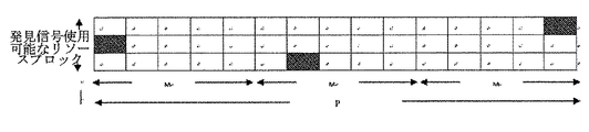
当該方案において、データ信号の初回伝送のための初送リソースはD2D通信のデータ伝送のためのデータ伝送リソースプールからランダムに選択されてもよく、当該リソースがデータ伝送リソースプールにおけるあるリソースブロックのインデックスに対応し、その後のK回の再送が当該リソースプール内の連続するKのリソースブロックが占めることで、受信側ユーザー機器が周波数帯域全体をモニタリングする必要がばくユーザー機器のモニタリング効率を向上させる。また、一回あたりの再送が占めるリソースブロックは少なくとも前回再送が占めるリソースブロックと異なり(好ましくは、隣り合わない)、これにより、一定の程度の周波数ダイバシティ利得を取得する。一回あたりの再送が占める具体的リソースブロックは例えば以下の方法の少なくとも一つにより確定される。 In the method, an initial transmission resource for initial transmission of a data signal may be randomly selected from a data transmission resource pool for data transmission of D2D communication, and the resource is an index of a certain resource block in the data transmission resource pool. In response, the subsequent K retransmissions are occupied by consecutive K resource blocks in the resource pool, which improves the monitoring efficiency of the user equipment that requires the receiving-side user equipment to monitor the entire frequency band. Also, the resource block occupied by one retransmission is different from at least the resource block occupied by the previous retransmission (preferably not adjacent), thereby obtaining a certain degree of frequency diversity gain. A specific resource block occupied by one retransmission is determined by at least one of the following methods, for example.
方法1:Kの数字をn*m(n≧2)の行列に分け、それぞれこのKの数字を行ごとに当該行列に記入し、その後列ごとに読み出された数字が各回再送が占めるリソースブロックインデックス番号に対応する。この際、一回あたりの再送と前回の伝送が占めるリソースブロックは不連続である。 Method 1: The number of K is divided into an n * m (n ≧ 2) matrix, the number of K is written in the matrix for each row, and then the number of retransmissions is occupied by the number read for each column. Corresponds to the block index number. At this time, the resource blocks occupied by one retransmission and the previous transmission are discontinuous.
方法2:k回目の再送が占めるリソースブロックのインデックス番号がI(k)=(a*k+b)mod K(k=1、2、…、K)となる。 Method 2: The index number of the resource block occupied by the k-th retransmission is I (k) = (a * k + b) mod K (k = 1, 2,..., K).
方法3:ランダムに1〜Kから一つの数字を順次抽出してk回目の再送が占めるリソースブロックのインデックス番号とする。 Method 3: Randomly extracting one number from 1 to K at random to obtain the index number of the resource block occupied by the k-th retransmission.
理解すべきことは、以上提供された周波数ホッピング方案設計は一例に過ぎず限定されるものではなく、当業者は相応する設計原則に応じて他の方案を想到することができる。 It should be understood that the frequency hopping scheme design provided above is only an example and is not limited, and those skilled in the art can conceive other schemes according to the corresponding design principle.
[1-2-1. mode2通信モードでの基地局側/クラスタヘッド側の配置の一例]
以下図9を参考してmode2通信モードでの基地局側/クラスタヘッド側の装置の機能構成の一例を記述する。図9は本開示の第1の実施例によるmode2通信モードでの基地局側/クラスタヘッド側の装置の機能構成の一例を示すブロック図である。
[1-2-1. Example of arrangement on base station side / cluster head side in
Hereinafter, an example of the functional configuration of the base station side / cluster head side apparatus in the
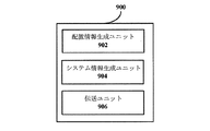
図9に示すように、装置900は、配置情報生成ユニット902と、システム情報生成ユニット904と、伝送ユニット906とを含むことができる。
As shown in FIG. 9, the
配置情報生成ユニット902は、D2D通信においてデータ信号に対して再送を行う回数を示す再送回数関連情報と、D2D通信におけるデータ信号伝送のためのリソースプールを示すデータ信号リソースプール情報とを少なくとも含む配置情報を生成するように配置されることができる。好ましくは、当該配置情報には、D2D通信におけるデータ信号再送に周波数ホッピング技術を応用するか否かを指示する再送周波数ホッピング指示識別子を含んでもよい。本開示の他の一つの一例において、データ信号リソースプールがシステムにより予め設定され、基地局側/クラスタヘッド側及び各ユーザー機器間にデフォルトのコンセンサスを有するので、配置情報生成ユニット902がデータ信号リソースプールの配置情報を生成しない。
Arrangement
システム情報生成ユニット904は、配置情報生成ユニット902が生成する配置情報をシステム情報ブロックに含ませるように配置されることができる。
The system
伝送ユニット906は、例えばブロードキャストの方式によりブロードキャスト制御チャネルを介して再送回数関連情報、データ信号リソースプール、及び再送周波数ホッピング指示識別子の少なくとも一つを含むシステム情報ブロックをD2D通信を行うユーザー機器に送信するように配置されることができる。
The
[1-2-2. mode2通信モードでの伝送側ユーザー機器側の配置の一例]
次に、図10ないし図12を参考してmode2通信モードでの伝送側ユーザー機器側の配置の一例を記述する。
[1-2-2. Example of arrangement on user equipment side on transmission side in mode2 communication mode]
Next, an example of the arrangement on the transmission-side user equipment side in the
図10は本開示の第1の実施例によるmode2通信モードでの伝送側ユーザー機器側の装置の機能構成の一例を示すブロック図である。
FIG. 10 is a block diagram illustrating an example of a functional configuration of an apparatus on the transmission-side user device side in the
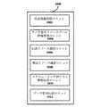
図10に示すように、装置1000は、再送回数受信ユニット1002、データ信号リソースプール情報受信ユニット1004と、伝送リソース選択ユニット1006と、再送リソース確定ユニット1008と、スケジューリング割り当て情報伝送ユニット1010と、データ信号伝送ユニット1012とを含むことができる。
As shown in FIG. 10,
再送回数受信ユニット1002は、D2D通信を行うユーザー機器間に再送を行うための回数を示す再送回数情報を受信するように配置されることができる。
The retransmission
データ信号リソースプール情報受信ユニット1004は、D2D通信におけるデータ信号伝送のためのデータ信号リソースプールを示す情報を受信するように配置されることができる。前記の基地局側/クラスタヘッド側の他の一例に対応して、データ信号リソースプールがシステムにより予め設定されたものである場合に、装置1000はデータ信号リソースプール情報受信ユニット1004を含まなくてもよい。
The data signal resource pool
伝送リソース選択ユニット1006は、データ信号リソースプールからデータ信号伝送を行うためのデータ信号伝送リソースを選択し当該伝送リソースを指示するリソース指示情報を生成するように配置されることができる。理解すべきことは、ここのデータ信号伝送リソースがデータ信号の初回伝送のための初送リソースを少なくとも含む。
The transmission
再送リソース確定ユニット1008は、少なくとも初送リソースに応じて、データ再送に周波数ホッピング技術を応用すると確定された場合に、前記予定の周波数ホッピング方法を採用してデータ信号再送を行うための再送リソースを確定するように配置されることができる。一つの一例において、再送リソース確定ユニット1008は、再送リソースの存在位置を直接指示する再送リソース指示を生成してもよい。
The retransmission
スケジューリング割り当て情報伝送ユニット1010は、データ信号伝送リソースに関する情報をスケジューリング割り当て情報に含ませて相手ユーザー機器に送信するように配置されることができる。データ信号伝送リソースに関する情報は、前記初送リソース指示を少なくとも含む。
The scheduling assignment
好ましくは、スケジューリング割り当て情報には、何種類の周波数ホッピング方法(例えば、前記方法1、2、3)を採用するかを指定する情報を含んでもよく、そして相応方法における周波数ホッピングパラメータ(例えば、前記のmとn又はaとb或いは発生するインデックスランダムシーケンス)を含む。しかしながら、理解すべきことは、予め何種類の周波数ホッピング方法を採用すると確定された場合に、スケジューリング割り当て情報において当該情報を含まなくてもよい。受信側ユーザー機器は、受信された初送リソース指示に応じて、相応する周波数ホッピング方法を採用して再送リソースを確定してもよい。D2D再送周波数ホッピングが通信システムのうち選択可能なメカニズムである場合に、スケジューリング割り当て情報において再送周波数ホッピングを応用するか否かを指示する再送周波数ホッピング指示を含んで受信側ユーザー機器に周波数ホッピングメカニズムに応じて再送リソースを確定させてもよい。また、好ましくは、スケジューリング割り当て情報には再送リソース指示を含んで採用する再送リソースを明確に指示してもよい。
Preferably, the scheduling assignment information may include information specifying how many types of frequency hopping methods (for example, the
データ信号伝送ユニット1012は、再送回数情報に応じて、相応するデータ信号伝送リソース上に(初送リソースと再送リソースとを含む)相手ユーザー機器へデータ信号を繰り返して伝送するように配置されることができる。
The data signal
理解すべきことは、以上のように、ここの再送回数受信ユニット1002と、データ信号リソースプール情報受信ユニット1004と、データ信号伝送ユニット1012とがいずれも例えば信号送受信ユニットにより実現されてもよく、スケジューリング割り当て情報伝送ユニット1010が例えば制御ユニットと信号送受信ユニットとにより実現されてもよく、そして、伝送リソース選択ユニット1006と再送リソース確定ユニット1008とが例えば制御ユニットにより実現されてもよい。具体的な信号送受信ユニットと制御ユニットとが端末製品における例えば無線通信インタフェース、プロセッサ等の素子の配置により実現されてもよい。
It should be understood that, as described above, the retransmission
図11は本開示の第1の実施例によるmode2通信モードでの伝送側ユーザー機器側の装置の他の一機能構成の一例を示すブロック図である。
FIG. 11 is a block diagram illustrating an example of another functional configuration of the device on the transmission-side user device side in the
図11に示すように、図10に示す装置1000と比べると、装置1100は、再送周波数ホッピング指示識別子受信ユニット1108がさらに設置され、他のユニットが装置1000における相応するユニットの機能構成と同じであるので、ここで重複して記述しない。以下再送周波数ホッピング指示識別子受信ユニット1108の機能構成の一例のみを詳細に記述する。
As illustrated in FIG. 11, compared with the
再送周波数ホッピング指示識別子受信ユニット1108は、D2D通信におけるデータ信号再送に周波数ホッピング技術を応用するか否かを指示する再送周波数ホッピング指示識別子を受信するように配置されることができる。 Retransmission frequency hopping instruction identifier receiving unit 1108 may be arranged to receive a retransmission frequency hopping instruction identifier that indicates whether to apply frequency hopping technology to data signal retransmission in D2D communication.
この際、再送リソース確定ユニット1110は、初送リソース指示と再送周波数ホッピング指示識別子とに基づいて、予定の周波数ホッピング方法を採用して再送リソースを確定するように配置されることができる。
At this time, the retransmission
理解すべきことは、以上のように、再送周波数ホッピング指示識別子受信ユニット1108が例えば信号送受信ユニットにより実現されてもよい。具体的な信号送受信ユニットが端末製品における例えば無線通信インタフェース等の素子の配置により実現されてもよい。 It should be understood that, as described above, the retransmission frequency hopping instruction identifier reception unit 1108 may be realized by a signal transmission / reception unit, for example. A specific signal transmission / reception unit may be realized by arrangement of elements such as a wireless communication interface in the terminal product.
図12は本開示の第1の実施例によるmode2通信モードでの伝送側ユーザー機器側の装置の他の一機能構成の一例を示すブロック図である。
FIG. 12 is a block diagram illustrating an example of another functional configuration of the device on the transmission-side user device side in the
図12に示すように、図10示す装置1000と比べると、装置1200は再送周波数ホッピング確定ユニット1208がさらに設置され、他のユニットが装置1000における相応するユニットの機能構成と同じであるので、ここで重複して記述しない。以下再送周波数ホッピング確定ユニット1208の機能構成の一例のみを詳細に記述する。
As shown in FIG. 12, compared with the
再送周波数ホッピング確定ユニット1208は、D2D通信におけるデータ信号再送に周波数ホッピング技術を応用するか否かを確定するように配置されることができる。
The retransmission frequency hopping
また、再送リソース確定ユニット1210は、確定された初送リソースと再送周波数ホッピングユニット1208の確定結果とに基づいて再送リソースを確定するように配置されることができる。
Also, retransmission
好ましくは、再送周波数ホッピング確定ユニット1208は、D2D通信におけるデータ信号再送に周波数ホッピング技術を応用するか否かを指示する再送周波数ホッピング指示識別子を生成して受信側ユーザー機器に周波数ホッピングメカニズムに応じて再送リソースを確定させるように配置されてもよい。この際、スケジューリング割り当て情報伝送ユニット1212は、初送リソース指示と再送周波数ホッピング指示識別子とをスケジューリング割り当て情報に含ませて相手ユーザー機器に伝送し、相手ユーザー機器に予定の周波数ホッピング方法に応じて初送リソースと再送リソースとを確定させるように配置されることができる。
Preferably, the retransmission frequency hopping
また、好ましくは、スケジューリング割り当て情報において再送リソースを指示する再送リソース指示をさらに含んでもよく、相手ユーザー機器に初送リソースと再送リソースとを明確に指示する。 Preferably, the scheduling allocation information may further include a retransmission resource instruction that indicates a retransmission resource, and clearly indicates the initial transmission resource and the retransmission resource to the counterpart user equipment.
理解すべきことは、以上のように、ここの再送周波数ホッピング確定ユニット1208が例えば制御ユニットにより実現されてもよい。具体的な制御ユニットが端末製品における例えばプロセッサ等の素子の配置により実現されてもよい。
It should be understood that, as described above, the retransmission frequency hopping
[1-2-3. mode2通信モードでの受信側ユーザー機器側の配置の一例]
次に図13を参考してmode2通信モードでの受信側ユーザー機器側の配置の一例を記述する。
[1-2-3. An example of the arrangement on the receiving user equipment side in
Next, an example of the arrangement on the receiving-side user device side in the
図13は本開示の第1の実施例によるmode2通信モードでの受信側ユーザー機器側の装置の機能構成の一例を示すブロック図である。
FIG. 13 is a block diagram illustrating an example of a functional configuration of an apparatus on the reception-side user device side in the
図13に示すように、図8に示す装置800と比べると、装置1300はデータ信号リソースプール情報受信ユニット1304がさらに設置され、他のユニットが装置800における相応するユニットの機能構成と同じであるので、ここで重複して記述しない。データ信号リソースプール情報受信ユニット1304の機能構成の一例のみを詳細に記述する。
As shown in FIG. 13, as compared with the
データ信号リソースプール情報受信ユニット1304は、D2D通信におけるデータ信号伝送のためのデータ信号リソースプールを示す情報を受信するように配置されることができる。
The data signal resource pool
伝送リソース確定ユニット1308は、受信されたデータ信号リソースプールの情報とスケジューリング割り当て情報とに基づいて相応する初送リソースと再送リソースとを確定するように配置されることができる。また、受信側ユーザー機器が自分で再送リソースを確定する場合に、周波数ホッピング操作を実行すると確定されたと、伝送リソース確定ユニット1308は受信されたデータ信号リソースプールの情報とスケジューリング割り当て情報とに応じて、相応する周波数ホッピング方法を利用して再送リソースを確定してもよい。
The transmission
理解すべきことは、以上のように、データ信号リソースプール情報受信ユニット1304が例えば信号送受信ユニットにより実現されてもよい。具体的な信号送受信ユニットが端末製品における例えば無線通信インタフェース等の素子の配置により実現されてもよい。
It should be understood that, as described above, the data signal resource pool
<2.第2の実施例>
本実施例では、D2D通信においてマルチセルシーンにおけるデータ信号伝送の方案設計を検討する。
<2. Second embodiment>
In the present embodiment, a design design of data signal transmission in a multi-cell scene in D2D communication is examined.
マルチセルシーンにおいて、D2D通信を行うユーザー機器が異なるセル内に分布し、各セルが異なる帯域配置を有する可能性がある。例えば、スモールセルの導入によって、大きい帯域のセルに配置されるリソースブロックインデックス番号について、シングルセルシーンに記述される周波数ホッピング方案に従って周波数ホッピングを行うと、得られるリソースブロックインデックス番号がスモールセルに全く存在しない可能性がある。従って、マルチセルシーンにおいて、各ユーザー機器が存在するセルの帯域配置を考慮して周波数ホッピング方案を設計する必要がある。 In a multi-cell scene, user devices that perform D2D communication may be distributed in different cells, and each cell may have a different band arrangement. For example, by introducing a small cell, if the frequency hopping is performed according to the frequency hopping method described in the single cell scene for the resource block index number arranged in a cell with a large band, the obtained resource block index number is completely assigned to the small cell. It may not exist. Therefore, in a multi-cell scene, it is necessary to design a frequency hopping method in consideration of the band arrangement of a cell in which each user device exists.
D2Dのmode1通信形態では、マルチセルシーンにおいてデータ信号に対する周波数ホッピング方案設計が以前記述されたシングルセルシーンと類似し、区別することは、まず、リソースブロックのインデックスを最も小さいセル帯域配置に従ってマッピングする必要があり、その後、シングルセルシーンと類似する形態に従って周波数ホッピング設計を行うことができる。具体的に、まず、初送リソースを、最も小さいセル帯域に対応するPUSCHリソース上にマッピングし、その後、最も小さいセル帯域に基づいて再送リソースを確定してもよい。好ましくは、再送リソースと前回伝送リソースとの間の周波数スパンが予定の閾値よりも大きく最も小さいセル帯域よりも小さくなる。
In the
その後のK回の再送の周波数リソースインデックスf(k)(k={1、2、…K−1})は次のように確定されることができる: The frequency resource index f (k) (k = {1, 2,... K−1}) for subsequent K retransmissions can be determined as follows:
また、マルチセルシーンにおいて、基地局側、伝送側ユーザー機器側、及び受信側ユーザー機器側の配置がシングルセルシーンと類似し、区別することは、伝送側ユーザー機器にサービスする基地局側の装置がセル帯域配置情報取得ユニットをさらに設置する必要があり、当該セル帯域配置情報取得ユニットは、D2D通信を行う各ユーザー機器が存在するセルのセル帯域配置情報を取得するように配置されて、リソーススケジューラにより割り当てられた伝送リソースを各ユーザー機器に対する統一的なインデックスで示す。好ましくは、伝送リソースが最も小さいセル帯域に対応するアップリンク伝送リソース上にマッピングされる。当該セル帯域配置情報取得ユニットは例えばX2インタフェースシグナリングにより各セルのセル帯域配置情報を取得してもよい。 In addition, in the multi-cell scene, the arrangement on the base station side, the transmission-side user equipment side, and the receiving-side user equipment side is similar to the single cell scene, and the distinction is that the equipment on the base station side that services the transmission-side user equipment It is necessary to further install a cell band arrangement information acquisition unit, and the cell band arrangement information acquisition unit is arranged to acquire cell band arrangement information of a cell in which each user device that performs D2D communication is present, and a resource scheduler The transmission resource allocated by is indicated by a unified index for each user equipment. Preferably, the transmission resource is mapped onto the uplink transmission resource corresponding to the smallest cell band. The cell band allocation information acquisition unit may acquire cell band allocation information of each cell by, for example, X2 interface signaling.
[2-2. mode2通信モードでの方案設計]
マルチセルシーンにおいて、mode2通信モードでの方案設計は、基本的に、シングルセルシーンと同じであり、特に、D2Dデータ通信のために、各セルにおいて同じデータ信号リソースプールを配置する。
[2-2. Plan design in
In the multi-cell scene, the design design in the
また、マルチセルシーンにおいて、mode2通信モードでの基地局側/クラスタヘッド側、伝送側ユーザー機器側、及び受信側ユーザー機器側の配置は、基本的に、シングルセルシーンと同じであり、区別することは、伝送側ユーザー機器にサービスする基地局が少なくとも取得された最も小さいセル帯域配置情報を伝送ユニットを介して伝送側ユーザー機器に送信する(必ず全ての帯域配置情報を送信するとは限らない)。好ましくは、当該サービス基地局が本セルの帯域が最も小さいと判断したとき、他のセルの帯域配置情報を送信する必要がない。また、オプションとして、伝送側ユーザー機器側の装置はセル帯域配置情報を受信するための帯域配置情報受信ユニットがさらに設置される必要があり、当該帯域配置情報受信ユニットが例えば信号送受信ユニットにより実現されてもよい。具体的な信号送受信ユニットが端末製品における例えば無線通信インタフェース等の素子の配置により実現されてもよい。
Also, in the multi-cell scene, the arrangement on the base station side / cluster head side, transmission-side user equipment side, and receiving-side user equipment side in the
この際、伝送側ユーザー機器側の装置は、最も小さいセル帯域に基づいてデータ信号のための初送リソースと再送リソースとを確定する。 At this time, the device on the transmission side user equipment determines the initial transmission resource and the retransmission resource for the data signal based on the smallest cell band.
<3.第3の実施例>
D2D通信において、発見過程がオプションであり、それがPUSCHリソース伝送MAC PDU(プロトコル データ ユニット)が占めるにより実現される。発見信号の伝送時間は予め定義された発見周期により決定され、当該周期内において、当該MAC PDUを繰り返して伝送することが可能である。D2D通信における発見過程とデータ通信過程の違いは、主に発見過程が半二重であり、これは、D2D通信を行うあるユーザー機器が発見信号を伝送する際に他のユーザー機器から伝送する発見信号を受信できないことを意味する。従って、発見信号に対する時間周波数リソース割り当て方案において、同時に時間領域と周波数領域リソースとの割り当てを考慮する必要がある。
<3. Third embodiment>
In D2D communication, the discovery process is optional and is realized by the PUSCH resource transmission MAC PDU (Protocol Data Unit). The transmission time of the discovery signal is determined by a predefined discovery period, and the MAC PDU can be transmitted repeatedly within the period. The difference between the discovery process and the data communication process in D2D communication is that the discovery process is mainly half-duplex, which is the discovery that a certain user device that performs D2D communication transmits from another user device when transmitting a discovery signal It means that the signal cannot be received. Therefore, in the time frequency resource allocation method for the discovery signal, it is necessary to consider the allocation of the time domain and the frequency domain resource at the same time.
発見信号について、予め発見信号リソースプールが配置され発見信号の伝送及び受信に専用するので、当該リソースプールにおいて伝送及び受信する全ての信号がいずれも発見信号と認められる。当該発見信号リソースプールはシステムが予め確定した又は基地局或いはクラスタヘッドにより例えば半静的に確定されてもよい。 Since the discovery signal resource pool is arranged in advance for the discovery signal and is dedicated to the transmission and reception of the discovery signal, all signals transmitted and received in the resource pool are recognized as discovery signals. The discovery signal resource pool may be predetermined by the system or semi-statically, for example, by the base station or cluster head.
また、D2D通信において、発見信号のための通信リソースの割り当て形態に応じて、発見信号に適する異なる時間周波数リソース割り当て方案を設計することが可能である。なお、発見信号の重要性に起因して、D2D通信においてデフォルトで再送を行う必要があり、周波数ホッピングをサポートすることができる。本開示の多くの好適な例において、デフォルトで発見信号再送に周波数ホッピング技術を応用する。オプションとして、基地局側又はクラスタヘッド側により周波数ホッピング技術を応用するか否かを決定し、周波数ホッピング技術を応用するか否かを指示する識別子をシステム情報ブロックに含ませてユーザー機器にブロードキャストしてもよい。又は、オプションとして、ユーザー機器が自分で周波数ホッピングを行うか否かを決定してもよい。 Further, in D2D communication, it is possible to design different time frequency resource allocation schemes suitable for discovery signals according to the communication resource allocation form for discovery signals. Note that due to the importance of the discovery signal, it is necessary to perform retransmission by default in D2D communication, and frequency hopping can be supported. In many preferred examples of this disclosure, frequency hopping techniques are applied to discovery signal retransmission by default. As an option, the base station side or the cluster head side decides whether or not to apply the frequency hopping technology, and an identifier indicating whether or not to apply the frequency hopping technology is included in the system information block and broadcast to the user equipment. May be. Alternatively, as an option, the user equipment may decide whether to perform frequency hopping by itself.
また、なお、発見信号に事前のスケジューリング割り当て情報通知がなく、身元認証情報(例えばRNTI等のID)も含まないので、物理レイヤにおいて、発見信号を受信したユーザー機器は当該発見信号がどちらのユーザー機器から送信されるかが分からない。従って、如何に同一ユーザー機器が複数回送信する発見信号を追従するのかは難しい問題となっている。本開示は、発見信号のための時間周波数リソース割り当て方案を進歩性に設計し、一回あたりの伝送リソースに対応する時間、周波数と次回の伝送リソースの時間、周波数とが関連付けられる。発見過程において、受信側ユーザー機器は発見信号リソースプールにおける全ての発見信号をモニタリングするとともに、初めて発見信号を受信した場合に、当該発見信号が存在する時間周波数リソースに応じて予定の時間周波数リソース割り当て方案と併せて次に伝送する毎の発見信号が存在する時間周波数リソースを確定することにより、次に伝送する全ての発見信号を受け取るとともに、上位レイヤプロトコルにより全ての発見信号を復号化することで発見信号に含まれる具体的な情報(例えば,伝送側ユーザー機器のID等)を確定する。 In addition, since there is no prior scheduling allocation information notification in the discovery signal and no identity authentication information (for example, ID such as RNTI) is included, in the physical layer, the user device that has received the discovery signal is the user whose discovery signal is I do not know if it is sent from the device. Therefore, it is a difficult problem how to follow the discovery signal transmitted by the same user device a plurality of times. In the present disclosure, a time-frequency resource allocation method for a discovery signal is designed as an inventive step, and the time and frequency corresponding to one transmission resource are associated with the time and frequency of the next transmission resource. During the discovery process, the receiving user equipment monitors all discovery signals in the discovery signal resource pool, and when receiving a discovery signal for the first time, assigns a scheduled time frequency resource according to the time frequency resource in which the discovery signal exists. By determining the time-frequency resource in which the discovery signal for each transmission next exists together with the scheme, all discovery signals to be transmitted next are received, and all discovery signals are decoded by the upper layer protocol. Specific information included in the discovery signal (for example, ID of the transmission-side user device) is determined.
<3-1. Type1発見メカニズムでの時間周波数リソースの割り当て方案設計>
図14ないし図17を参考して本開示の第3の実施例によるD2D通信のType1発見メカニズムでの発見信号伝送に対する時間周波数リソース割り当て方案設計を記述する。
<3-1. Design of time frequency resource allocation scheme with Type1 discovery mechanism>
A time-frequency resource allocation plan design for discovery signal transmission in the
Type1発見メカニズムとは、発見信号伝送のためのリソース(時間領域と周波数領域リソースとを含む)の割り当てがユーザー機器に基づくものではなく、全てのユーザー機器又は一組のユーザー機器がこれらのリソースを共有し、これらのリソースが予め割り当てられることが可能であることを指す。このリソース割り当て方式は実質的に分布型のリソース割り当てに属するので、従って、如何にユーザー機器が自分で選択する時間周波数リソース間の衝突及び半二重の不利な要因を最大限に避けるかは、この場合の時間周波数リソース割り当て方案設計の重点であろう。
The
本開示の発明者は設計する際に、異なるユーザー機器が同一時間周波数リソースを選択する可能性をできるだけ低減するとともに、同一時間周波数リソースをランダムに選択したユーザー機器に対して、後続の再送においてそれが使用する時間リソースをなるべく隔てる。 The inventor of the present disclosure reduces the possibility of different user equipments selecting the same time-frequency resource as much as possible during design, and in subsequent retransmissions for user equipments that randomly select the same time-frequency resource. Separate the time resources used by as much as possible.
図14は当該時間周波数リソース割り当て方案によって得られる時間周波数リソースの分布図を示す。図14に示すように、一回あたりの伝送が占める時間領域と周波数領域リソースとがいずれも異なる。理解すべきことは、ここで記述する時間周波数リソース割り当て方案は一例に過ぎず限定されるものではなく、そして当業者が設計原則に応じて異なる時間周波数リソース割り当て方案を設計することが可能である。 FIG. 14 shows a distribution diagram of time frequency resources obtained by the time frequency resource allocation method. As shown in FIG. 14, both the time domain and frequency domain resources occupied by one transmission are different. It should be understood that the time-frequency resource allocation scheme described here is only an example and is not limited, and a person skilled in the art can design different time-frequency resource allocation schemes according to design principles. .
Type1発見メカニズムにおいて、発見信号リソースプール、発見周期、及び再送回数関連情報(再送回数又は再送周期)の配置情報は、システム情報ブロックに含ませることにより、ブロードキャストの方式によりD2D通信を行う全てのユーザー機器に通知されることができる。前に記述された例と類似して、発見信号リソースプール、発見周期等の情報がシステムが予め設定したものである場合に、配置情報にこれらの情報を含まなくてもよい。
In the
[3-1-1. Type1発見メカニズムでの基地局側/クラスタヘッド側の配置の一例]
次に、図15を参考してType1発見メカニズムでの基地局側/クラスタヘッド側の装置の機能構成の一例を記述する。図15は本開示の第3の実施例によるType1発見メカニズムでの基地局側/クラスタヘッド側の装置の機能構成の一例を示すブロック図である。
[3-1-1. Example of arrangement on base station side / cluster head side in
Next, an example of the functional configuration of the base station side / cluster head side device in the
図15に示すように、装置1500は、配置情報生成ユニット1502と、システム情報生成ユニット1504と、伝送ユニット1506とを含むことができる。
As shown in FIG. 15, the
配置情報生成ユニット1502は、再送回数関連情報と発見信号のための発見周期情報とを含む配置情報を生成するように配置されることができる。発見周期において、D2D通信を行うユーザー機器が発見信号を伝送する。その中、本開示の幾つかの例において、発見周期が特定の一定の時期であってもよく、その配置情報が例えば発見開始時間、発見終了時間を含み、本開示の他の幾つかの例において、発見周期が循環して重複時間区間であってもよく、その配置情報が例えば発見周期の長さ、重複周期を含む。理解すべきことは、ここの再送回数関連情報とは再送周期又は再送回数を指してもよい。
The arrangement
好ましくは、配置情報生成ユニット1502が生成した配置情報には発見信号伝送のための発見信号リソースプールの情報をさらに含んでもよく、当該発見信号リソースプールがD2D通信を行う全てのユーザー機器により共有される。代わりに、当該発見信号リソースプールは、基地局/クラスタヘッドにより割り当てる必要がなく、予め配置されていてもよい。
Preferably, the arrangement information generated by the arrangement
システム情報生成ユニット1504は、配置情報をシステム情報ブロックに含ませるように配置されることができる。
The system
伝送ユニット1506は、システム情報ブロックを例えばブロードキャストの方式によりD2D通信を行うユーザー機器に送信するように配置されることができる。
The
[3-1-2. Type1発見メカニズムでの伝送側ユーザー機器側の配置の一例]
次に、図16を参考して本開示の第3の実施例によるType1発見メカニズムでの伝送側ユーザー機器側の装置の機能構成の一例を記述する。図16は本開示の第3の実施例によるType1発見メカニズムでの伝送側ユーザー機器側の装置の機能構成の一例を示すブロック図である。
[3-1-2. An example of the arrangement on the user equipment side on the transmission side in the
Next, an example of a functional configuration of the apparatus on the transmission-side user device side in the
図16に示すように、装置1600は、発見周期情報受信ユニット1602と、再送回数情報受信ユニット1604と、発見信号リソースプール情報受信ユニット1606と、伝送リソース確定ユニット1608と、発見信号伝送ユニット1610とを含むことができる。
As shown in FIG. 16,
発見周期情報受信ユニット1602は、発見信号を伝送するための発見周期の情報を受信するように配置されることができる。 The discovery period information receiving unit 1602 may be arranged to receive discovery period information for transmitting a discovery signal.
再送回数情報受信ユニット1604は、発見周期において発見信号を再送する回数に関する情報を受信するように配置されることができる。当該再送回数関連情報が再送回数又は再送周期であってもよい。
The retransmission number
発見信号リソースプール情報受信ユニット1606は、発見信号伝送のための発見信号リソースプールの情報を受信するように配置されることができる。理解すべきことは、発見信号リソースプールが予め配置された場合に、発見信号リソースプール受信ユニット1606を設置しなくてもよい。 The discovery signal resource pool information receiving unit 1606 may be arranged to receive discovery signal resource pool information for discovery signal transmission. It should be understood that the discovery signal resource pool receiving unit 1606 may not be installed when the discovery signal resource pool is arranged in advance.
伝送リソース確定ユニット1608は、発見信号リソースプールから発見信号の初回伝送のための初送リソースをランダムに選択するとともに、予定のジャンプ関数(例えば、前記例示する際に時間周波数リソース割り当て方案)に基づいて発見周期内で他の一回あたりの伝送リソースの時間領域と周波数領域と異なる再送回数の再送リソースを周期的に選択するように配置されることができる。
The transmission
発見信号伝送ユニット1610は、再送回数関連情報に応じて、確定された初送リソースと再送リソースとで発見信号を繰り返して伝送するように配置されることができる。
The discovery
理解すべきことは、前記のように、ここの発見周期情報受信ユニット1602と、再送回数情報受信ユニット1604と、発見信号リソースプール情報受信ユニット1606と、発見信号伝送ユニット1610とがいずれも例えば信号送受信ユニットにより実現されてもよく、そして、伝送リソース確定ユニット1608が例えば制御ユニットにより実現されてもよい。具体的な信号送受信ユニットと制御ユニットとが端末製品における例えば無線通信インタフェース、プロセッサ等の素子の配置により実現されてもよい。
It should be understood that, as described above, the discovery cycle information receiving unit 1602, the retransmission count
<3-1-3. Type1発見メカニズムでの受信側ユーザー機器側の配置の一例>
次に、図17を参考して本開示の第3の実施例によるType1発見メカニズムでの受信側ユーザー機器側の装置の機能構成の一例を記述する。図17は本開示の第3の実施例によるType1発見メカニズムでの受信側ユーザー機器側の装置の機能構成の一例を示すブロック図である。
<3-1-3. An example of the arrangement on the receiving user equipment side in the
Next, an example of the functional configuration of the device on the receiving-side user device side in the
図17に示すように、装置1700は、発見周期情報受信ユニット1702と、再送回数情報受信ユニット1704と、発見信号リソースプール情報受信ユニット1706と、伝送リソース確定ユニット1708と、発見信号受信ユニット1710と、発見信号復号化ユニット1712とを含むことができる。なお、発見周期情報受信ユニット1702と、再送回数情報受信ユニット1704と、発見信号リソースプール情報受信ユニット1706との機能構成の一例は前記図16に示す発見周期情報受信ユニット1602と、再送回数情報受信ユニット1604と、発見信号リソースプール情報受信ユニット1606との機能構成の一例と同じであるので、ここで重複して記述しない。ここで伝送リソース確定ユニット1708と、発見信号受信ユニット1710と、発見信号復号化ユニット1712との機能構成の一例のみを詳細に記述する。
As shown in FIG. 17,
発見信号受信ユニット1710は、発見周期内で発見信号リソースプールに対応する周波数領域範囲をモニタリングするように配置されることができ、そして、発見信号を受信した場合に、伝送リソース確定ユニット1708は、当該発見信号が存在する時間周波数リソースと予定のジャンプ関数とに応じて次回の発見信号伝送のための時間周波数リソースを確定するように配置されることができ、これにより、発見信号受信ユニット1710は、確定された一回あたりの発見信号伝送のための時間周波数リソースに応じて相手ユーザー機器から伝送する全ての発見信号を受信することができる。
The discovery
発見信号復号化ユニット1712は、受信された全ての発見信号に対して例えば上位レイヤの統合復号化を行って発見信号に含まれる情報を取得するように配置されることができる。例えば、当該情報には相手ユーザー機器のID(例えば、無線ネットワーク一時識別子(RNTI))等が少なくとも含まれる。受信側ユーザー機器に相手ユーザー機器とD2D通信を行うか否かを確定させるために、当該情報に相手ユーザー機器D2D通信の目的、目標通信対象等の情報をさらに含んでもよい。
The discovery
理解すべきことは、前記のように、ここの発見周期情報受信ユニット1702と、再送回数情報受信ユニット1704と、発見信号リソースプール情報受信ユニット1706と、発見信号受信ユニット1710とがいずれも例えば信号送受信ユニットにより実現されてもよく、そして、伝送リソース確定ユニット1708と発見信号復号化ユニット1712とが例えば制御ユニットにより実現されてもよい。
It should be understood that, as described above, the discovery cycle information receiving unit 1702, the retransmission count
[3-2. Type2(Type2AとType2Bとを含む)発見メカニズムでの時間周波数リソース割り当て方案設計]
以下図18を参考して本開示の第3の実施例によるD2D通信のType2発見メカニズムでの発見信号伝送に対する時間周波数リソース割り当て方案設計を記述する。
[3-2. Design of time-frequency resource allocation scheme in Type 2 (including Type 2A and Type 2B) discovery mechanism]
Hereinafter, a time-frequency resource allocation plan design for discovery signal transmission in the
Type2発見メカニズムとは発見信号のためのリソースの割り当てがユーザー機器に基づくことを指し、それがType2AとType2Bの二つのモードに細かく分け、なお、Type2Aとは一回あたりの発見信号伝送においてそのリソースを独立して割り当て、基地局又はクラスタヘッドにより統合的に割り当てることを指し、Type2Bとは、発見信号伝送のためのリソースが半静的に配置されることを指す。
The
Type2A発見メカニズムでの時間周波数リソース割り当て方案は既存の基地局によりユーザー機器に初送リソースと再送リソースとをまとめて割り当てる形態と類似するので、ここで重複して記述しない。伝送側ユーザー機器が、割り当てられた発見信号の一回あたりの伝送のための時間周波数リソース上で発見信号を伝送し、受信側ユーザー機器が発見信号リソースプールに対応する周波数領域範囲をモニタリングし、発見信号を受信した後、当該発見信号が存在する時間周波数リソースに応じて、予定のアルゴリズムと併せて後続の再送の発見信号が存在する時間周波数リソースを推計することにより、伝送する全ての発見信号を受信する。理解すべきことは、周波数ホッピング技術を応用する場合には、割り当てられる、発見信号の伝送あたりのための時間領域と周波数領域リソースとがいずれも前回の伝送が占める時間領域と周波数領域リソースと異なることを確定するはずである。Type2Aにおいて、初送リソースが統合管理装置により各伝送待ちユーザー機器にまとめて割り当てられるので、複数の伝送側ユーザー機器が同じ時間周波数リソースを利用して初送することが発生せず、従って、図2と類似する形態を利用して周波数ホッピングを行って再送周波数領域リソースを確定して、時間領域において例えば、nのサブフレームごとに(nが例えば0よりも大きい)対応する時間領域を再送時間領域とするようにまとめる。以下Type2B発見メカニズムでの時間周波数リソース割り当て方案のみを詳細に記述する。 The time-frequency resource allocation method in the Type 2A discovery mechanism is similar to the mode in which the initial transmission resource and the retransmission resource are allocated to the user equipment by the existing base station, and thus will not be described here. The transmitting user equipment transmits the discovery signal on a time frequency resource for a single transmission of the assigned discovery signal, and the receiving user equipment monitors the frequency domain range corresponding to the discovery signal resource pool; After receiving a discovery signal, all the discovery signals to be transmitted are estimated by estimating the time-frequency resource in which a subsequent retransmission discovery signal exists together with a scheduled algorithm according to the time-frequency resource in which the discovery signal exists. Receive. It should be understood that, when applying frequency hopping technology, the time domain and frequency domain resources allocated for transmission of discovery signals are both different from the time domain and frequency domain resources occupied by the previous transmission. It should be confirmed. In Type 2A, the initial transmission resources are collectively allocated to the transmission-waiting user devices by the integrated management apparatus, so that a plurality of transmission-side user devices do not first transmit using the same time-frequency resource. 2, frequency retransmission is performed using a form similar to 2 to determine retransmission frequency domain resources, and for example, in the time domain, for each n subframes (where n is greater than 0), the corresponding time domain is the retransmission time. Put together to be an area. Hereinafter, only the time frequency resource allocation method in the Type 2B discovery mechanism will be described in detail.
まず、基地局又は中心ノード(例えば、クラスタヘッド)によりD2D通信を行うことを要求するユーザー機器の数に応じて発見信号伝送のための発見信号リソースプールを、互いに直交する複数のサブリソースプールに区分するとともに(例えば、各サブリソースプールと他のサブリソースプールに含まれるリソースブロックとがいずれも異なる)、これらの複数のリソースプールを、D2D通信を行うことを要求するユーザー機器にそれぞれに割り当てもよい。また、各ユーザー機器が利用可能な再送回数がユーザー機器全体の数に応じて確定されてもよい。理解すべきことは、各サブリソースプールが互いに直交するので、発見信号を送信するために異なるユーザー機器が同一時間周波数リソースを選択した可能性を避ける。例示的形態として、以下の形態により時間領域と周波数領域リソースの割り当てを行うが、本開示はこれに限定されない。 First, a discovery signal resource pool for discovery signal transmission is changed into a plurality of sub-resource pools orthogonal to each other according to the number of user equipments that request to perform D2D communication by a base station or a central node (for example, cluster head). In addition to partitioning (for example, each sub-resource pool and resource blocks included in other sub-resource pools are all different), these multiple resource pools are assigned to user devices that request D2D communication, respectively. Also good. Further, the number of retransmissions that can be used by each user device may be determined according to the total number of user devices. It should be understood that each sub-resource pool is orthogonal to each other, thus avoiding the possibility that different user equipments have selected the same time frequency resource to transmit discovery signals. As an exemplary form, time domain and frequency domain resources are allocated according to the following form, but the present disclosure is not limited to this.
その後のk回目の伝送が占める周波数領域リソースf(k)と時間領域t(k)とはそれぞれ: The frequency domain resource f (k) and time domain t (k) occupied by the subsequent k-th transmission are respectively:
当該発見メカニズムにおいて、基地局/クラスタヘッドは専用のシグナリング(例えば、無線リソース制御プロトコル(RRC)シグナリング)によりユーザー機器に、区分されたサブリソースプール情報及び再送回数関連情報(例えば、再送周期又は再送回数)を通知する。また、当該専用のシグナリングには発見周期の配置情報をさらに含んでもよい。 In the discovery mechanism, the base station / cluster head sends the sub-resource pool information and the retransmission count related information (for example, retransmission period or retransmission) to the user equipment by dedicated signaling (for example, radio resource control protocol (RRC) signaling). Number of times). The dedicated signaling may further include discovery period arrangement information.
[3-2-1. Type2B発見メカニズムでの基地局側/クラスタヘッド側の配置の一例]
Type2A発見メカニズムにおいて、基地局側/クラスタヘッド側、伝送側ユーザー機器側、及び受信側ユーザー機器側の配置はType1発見メカニズムと類似し、区別することは、この際基地局側がさらに例えばシングルセルmode1通信モードにおけるリソーススケジューラ406とリソース割り当て情報生成ユニット408とを設置して発見信号伝送のための伝送リソース(少なくとも初送リソースを含み、再送リソースを含んでもよい)を割り当て伝送リソースの指示情報を生成する必要があるとともに、伝送ユニットにより伝送リソースの指示情報を伝送側ユーザー機器に送信し、伝送側ユーザー機器側が発見信号のための初送リソースを選択する必要がなく、相応するリソース受信ユニットを設置して基地局又はクラスタヘッドの割り当てる伝送リソースを受信する必要がある。他の詳細に記述しない内容について、Type1発見メカニズムでの相応箇所の記述を参考し、ここで重複しない。
[3-2-1. An example of arrangement on the base station side / cluster head side in the Type 2B discovery mechanism]
In the Type 2A discovery mechanism, the arrangement on the base station side / cluster head side, transmission side user equipment side, and reception side user equipment side is similar to the
次に図18を参考して本開示の第3の実施例によるType2B発見メカニズムでの基地局側/クラスタヘッド側の装置の機能構成の一例を記述する。図18は本開示の第3の実施例によるType2B発見メカニズムでの基地局側/クラスタヘッド側の装置の機能構成の一例を示すブロック図である。 Next, an example of a functional configuration of the base station side / cluster head side apparatus in the Type 2B discovery mechanism according to the third embodiment of the present disclosure will be described with reference to FIG. FIG. 18 is a block diagram illustrating an example of a functional configuration of an apparatus on the base station side / cluster head side in the Type 2B discovery mechanism according to the third embodiment of the present disclosure.
図18に示すように、装置1800は、配置情報生成ユニット1802と、リソースプール区分ユニット1804と、伝送ユニット1806とを含むことができる。
As shown in FIG. 18, the
配置情報生成ユニット1802は、再送回数関連情報と発見周期情報とを含む配置情報を生成するように配置されることができる。
The arrangement
リソースプール区分ユニット1804は、D2D通信を行うことを要求するユーザー機器の数に応じて予め配置された発見信号リソースプールを、互いに直交する複数のサブリソースプールに区分するように配置されることができる。
The resource
伝送ユニット1806は、専用のシグナリング(例えば、RRCシグナリング)により配置情報とサブリソースプールの情報とを相応するユーザー機器に送信するように配置されることができる。オプションとして、基地局側/クラスタヘッド側により発見信号リソースプールを配置する場合に、伝送ユニット1806は、さらに、ブロードキャスト方式により発見信号リソースプールの情報を各ユーザー機器に伝送してもよい。
The
[3-2-2. Type2B発見メカニズムでのユーザー機器側の配置の一例]
Type2B発見メカニズムにおいて、ユーザー機器側(伝送側ユーザー機器側と受信側ユーザー機器側を含む)の装置の機能構成は前記Type1発見メカニズムでの機能構成と類似し、区別することは、伝送リソース確定ユニットがType1発見メカニズムと異なるアルゴリズム/ジャンプ関数に応じて再送リソースを確定する。また、伝送側ユーザー機器は、基地局側/クラスタヘッド側が割り当てる、当該ユーザー機器が発見信号を送信するためのサブリソースプールの情報を受信するように配置されるサブリソースプール情報受信ユニットがさらに設置されてもよく、その中、各ユーザー機器のためのサブリソースプールが互いに直交する。従って、伝送側ユーザー機器は、それに割り当てたサブリソースプールから発見信号のための初送リソースをランダムに選択し、予定のアルゴリズムに応じて再送リソースを確定するとともに、確定された初送リソースと再送リソース上に相手ユーザー機器へ発見信号を繰り返して送信する。Type1発見メカニズムにおける発見信号リソースプール情報受信ユニットを多重して前記サブリソースプール情報を受信し、受信されるリソースプール内容のみが異なることが理解される。受信側ユーザー機器は、初めて発見信号を受信した後、当該発見信号が存在する時間周波数リソースに応じて、Type2B発見メカニズムでの予定のアルゴリズムに基づいて後続の再送の発見信号が存在する時間周波数リソースを推計することにより、推計された後続の時間周波数リソースをモニタリングすることで伝送する全ての発見信号を受信する。
[3-2-2. An example of arrangement on the user equipment side in the Type 2B discovery mechanism]
In the Type 2B discovery mechanism, the functional configuration of the device on the user equipment side (including the transmission side user equipment side and the reception side user equipment side) is similar to the functional configuration in the
<4.第4の実施例>
D2D通信において、前記伝送側ユーザー機器が受信側ユーザー機器へ伝送するスケジューリング割り当て情報について、本開示の幾つかの例においても再送を行うように設計され、且つそれが再送周波数ホッピングもサポートするが、受信側ユーザー機器に具体的な伝送リソース情報及び周波数ホッピングを行うか否か(例えばデフォルトで周波数ホッピングを行う)を通知する必要がない。スケジューリング割り当て情報の周波数ホッピング方案はデータ信号に対する周波数ホッピング方案と類似するので,ここで重複して記述しない。
<4. Fourth embodiment>
In D2D communication, the scheduling assignment information transmitted from the transmission-side user equipment to the reception-side user equipment is designed to perform retransmission in some examples of the present disclosure, and it supports retransmission frequency hopping, It is not necessary to notify the receiving-side user device whether or not to perform specific transmission resource information and frequency hopping (for example, frequency hopping is performed by default). Since the frequency hopping scheme for scheduling allocation information is similar to the frequency hopping scheme for data signals, it will not be described here again.
具体的に、伝送側ユーザー機器は、受信された再送回数関連情報に応じて、予め設置されたスケジューリング割り当て情報リソースプールにおいて(例えば、RRCシグナリングにより半静的に配置する又は静的に配置する)選択した初送リソースと再送リソース上に受信側ユーザー機器へスケジューリング割り当て情報を繰り返して送信してもよい。相応に、受信側ユーザー機器は、受信された再送回数関連情報に応じて、予め配置されたスケジューリング割り当て情報リソースプールに対応する周波数範囲で伝送側ユーザー機器からの全てのスケジューリング割り当て情報をモニタリングしてもよい。即ち、受信側ユーザー機器は予め配置されたスケジューリング割り当て情報リソースプールを検索する(即ち、ブラインド検出)とともに、伝送あたりのスケジューリング割り当て情報を受信する。例えば、受信側ユーザー機器は例えばスケジューリング割り当て情報を担持する信号に含まれるRNTIに応じて自分に送信する全てのスケジューリング割り当て情報を検出してもよい。 Specifically, the transmission-side user equipment is configured in a scheduling allocation information resource pool that is installed in advance according to the received information related to the number of retransmissions (for example, semi-statically or statically allocated by RRC signaling). The scheduling assignment information may be repeatedly transmitted to the receiving-side user equipment on the selected initial transmission resource and retransmission resource. Correspondingly, the receiving-side user equipment monitors all scheduling assignment information from the transmitting-side user equipment in the frequency range corresponding to the pre-arranged scheduling assignment information resource pool according to the received retransmission count related information. Also good. That is, the receiving-side user device searches for a scheduling allocation information resource pool that is arranged in advance (that is, blind detection) and receives scheduling allocation information per transmission. For example, the receiving-side user equipment may detect all scheduling assignment information transmitted to itself according to, for example, an RNTI included in a signal carrying scheduling assignment information.
以上例示として装置実施例の機能構成の一例を記述したが、当業者であれば本開示の原理に応じて、修正、組み合わせ、添加及び/又は削除を行うことができ、このような変形がもちろん本開示の範囲に属するものと了解される。 Although an example of the functional configuration of the apparatus embodiment has been described above as an example, those skilled in the art can make modifications, combinations, additions and / or deletions according to the principles of the present disclosure, and such variations are of course possible. It is understood that it belongs to the scope of the present disclosure.
以上の装置実施例に対応して、本開示は相応する方法実施例をさらに提供する。 In response to the above apparatus embodiments, the present disclosure further provides corresponding method embodiments.
図19は本開示の実施例による無線通信システムにおける方法の一例手順を示すフローチャートである。 FIG. 19 is a flowchart illustrating an example procedure of a method in a wireless communication system according to an embodiment of the present disclosure.
図19に示すように、当該方法は、配置情報生成ステップS1902と、伝送ステップS1904とを含む。 As shown in FIG. 19, the method includes an arrangement information generation step S1902 and a transmission step S1904.
配置情報生成ステップS1902において、D2D(Device to Device)通信を行うユーザー機器間の信号伝送の再送回数に関する情報を示す再送回数関連情報を含む、D2D(Device to Device)通信を行うためのユーザー機器の配置情報を生成する。 In the arrangement information generation step S1902, the user equipment for performing D2D (Device to Device) communication, including information related to the number of retransmissions indicating the number of retransmissions of signal transmission between user apparatuses performing D2D (Device to Device) communication. Generate placement information.
伝送ステップS1904において、生成した配置情報をD2D(Device to Device)通信を行うユーザー機器に伝送する。 In transmission step S1904, the generated arrangement information is transmitted to a user device that performs D2D (Device to Device) communication.
図20は本開示の他の一実施例の無線通信システムにおける方法の一例手順を示すフローチャートである。 FIG. 20 is a flowchart illustrating an example procedure of a method in the wireless communication system according to another embodiment of the present disclosure.
図20に示すように、当該方法は、信号送受信ステップS2002と、制御ステップS2004とを含むことができる。 As shown in FIG. 20, the method can include a signal transmission / reception step S2002 and a control step S2004.
信号送受信ステップS2002において、D2D(Device to Device)通信を行うユーザー機器間の信号伝送の再送回数に関する情報を示す再送回数関連情報を含む配置情報を受信する。 In signal transmission / reception step S2002, arrangement information including information related to the number of retransmissions indicating information related to the number of retransmissions of signal transmission between user devices performing D2D (Device to Device) communication is received.
制御ステップS2004において、受信された再送回数関連情報に応じて、信号送受信ステップS2002で相手ユーザー機器へ信号を繰り返して伝送するように制御する。理解すべきことは、ここの信号にはデータ信号、発見信号及びスケジューリング割り当て情報の少なくとも一つを含む。 In control step S2004, control is performed so that the signal is repeatedly transmitted to the partner user device in signal transmission / reception step S2002 in accordance with the received retransmission count related information. It should be understood that the signal here includes at least one of a data signal, a discovery signal and scheduling assignment information.
図21は本開示の他の一実施例による無線通信システムにおける方法の一例手順を示すフローチャートである。 FIG. 21 is a flowchart illustrating an example procedure of a method in a wireless communication system according to another embodiment of the present disclosure.
図21に示すように、当該方法は、信号送受信ステップS2102と、制御ステップS2104とを含むことができる。 As shown in FIG. 21, the method can include a signal transmission / reception step S2102 and a control step S2104.
信号送受信ステップS2102において、D2D(Device to Device)通信を行うユーザー機器の信号伝送の再送回数に関する情報を示す再送回数関連情報を含む配置情報を受信する。 In signal transmission / reception step S2102, arrangement information including information related to the number of retransmissions indicating information related to the number of retransmissions of signal transmission of the user equipment that performs D2D (Device to Device) communication is received.
制御ステップS2104において、受信された再送回数関連情報に応じて、信号送受信ステップS2002で相手ユーザー機器から伝送する全ての信号を受信するように制御する。 In control step S2104, control is performed so as to receive all signals transmitted from the counterpart user device in signal transmission / reception step S2002 in accordance with the received retransmission count related information.
なお、ここの方法実施例は前記装置実施例に対応するので、方法実施例において詳細に記述しない内容について、装置実施例における相応箇所の記述を参考し、ここで重複して記述しない。 It should be noted that the method embodiment here corresponds to the device embodiment described above, so that the contents not described in detail in the method embodiment are referred to the description of the corresponding parts in the device embodiment, and are not described here.
理解すべきことは、本開示の実施例による記憶媒体とプログラム製品における機械が実行可能な命令はさらに、前記装置実施例に対応する方法を実行するように配置されるので、ここで詳細に記述しない内容について、前の相応箇所の記述を参考し、ここで重複して記述しない。 It should be understood that the machine-executable instructions in the storage medium and program product according to embodiments of the present disclosure are further arranged to perform a method corresponding to the apparatus embodiment, and will be described in detail herein. For the contents not to be used, refer to the description of the corresponding part before, and do not repeat them here.
相応に、前記した機械が実行可能な命令コードを含むプログラム製品を搭載するための記憶媒体も本発明の開示に含まれる。前記記憶媒体は、フロッピーディスク、光ディスク、磁気光ディスク、メモリカード、メモリスティックなどが含まれるが、それらに限定されない。 Correspondingly, a storage medium for mounting a program product including an instruction code executable by the machine is also included in the disclosure of the present invention. Examples of the storage medium include, but are not limited to, a floppy disk, an optical disk, a magnetic optical disk, a memory card, and a memory stick.
また、さらに指摘すべきことは、前記の一連の処理と装置はソフトウェア及び/又はファームウェアで実現できる。ソフトウェア或いはファームウェアで実現する場合、記憶媒体或いはネットワークから専用ハードウェア構造を有するコンピュータ、例えば図22に示す汎用パーソナルコンピューター2200に当該ソフトウェアを構成するプログラムをインストールし、当該コンピュータは各種のプログラムがインストールされている場合、各種の機能等を実行できる。
Further, it should be pointed out that the above-described series of processing and apparatus can be realized by software and / or firmware. When realized by software or firmware, a program constituting the software is installed from a storage medium or a network to a computer having a dedicated hardware structure, for example, a general-purpose
図22において、演算処理ユニット(CPU)2201は、読取専用メモリ(ROM)2202に記憶されているプログラム或いは記憶部2208からランダムアクセスメモリ(RAM)2203にロードしたプログラムに基づいて各種の処理を実行する。RAM2203にも、必要に応じてCPU2201が各種の処理等を実行する際に必要なデータが記憶される。
In FIG. 22, an arithmetic processing unit (CPU) 2201 executes various processes based on a program stored in a read-only memory (ROM) 2202 or a program loaded from a
CPU2201、ROM2202、RAM2203はバス2204を介して互いに接続されている。入力/出力インタフェース2205もバス2204に接続されている。
The
入力部2206(キーボード、マウス等を含む)、出力部2207(ディスプレイ、例えば陰極線管(CRT)、液晶ディスプレイ(LCD)等、スピーカ等を含む)、記憶部2208(ハードディスク等を含む)、通信部2209(ネットワークインターフェースカード例えばLANカード、モデム等を含む)が入力/出力インタフェース2205に接続される。通信部2209は、ネットワーク、例えばインターネットを介して通信処理を実行する。
Input unit 2206 (including keyboard, mouse, etc.), output unit 2207 (display, including cathode ray tube (CRT), liquid crystal display (LCD), etc., speaker), storage unit 2208 (including hard disk, etc.), communication unit 2209 (including a network interface card such as a LAN card, a modem, etc.) is connected to the input /
必要に応じて、ドライバー2210も入力/出力インタフェース2205に接続される。リムーバブルメディア2211、例えばディスク、光ディスク、光磁気ディスク、半導体メモリ等は、必要に応じてドライバー2210に装着され、その中から読み出したコンピュータプログラムが必要に応じて記憶部2208にインストールされるようになる。
A
ソフトウェアで前記一連の処理を実現する場合、ネットワーク、例えばインターネット或いは記憶装置、例えばリムーバブルメディア2211からソフトウェアを構成するプログラムをインストールする。
When the series of processing is realized by software, a program constituting the software is installed from a network, for example, the Internet or a storage device, for example,
当業者であれば、この種の記憶媒体は、図22に示す、その中にプログラムが記憶され装置に別途配分してユーザーにプログラムを提供するリムーバブルメディア2211に限定されないことが理解される。リムーバブルメディア2211の例は、磁気ディスク(フロッピーディスク(登録商標))、光ディスク(光ディスク読取専用メモリ(CD−ROM)とデジタル多用途ディスク(DVD)を含む)、光磁気ディスク(ミニディスク(MD)(登録商標)を含む)、半導体メモリを含む。又は、記憶媒体は、ROM2202、記憶部2208に含まれるハードディスク等であってもよく、その中にプログラムが記憶され、且つこれらを含む装置と一緒にユーザーに配分される。
A person skilled in the art understands that this type of storage medium is not limited to the removable medium 2211 shown in FIG. 22 in which the program is stored and separately distributed to the apparatus and provided to the user. Examples of the removable medium 2211 include a magnetic disk (floppy disk (registered trademark)), an optical disk (including an optical disk read-only memory (CD-ROM) and a digital versatile disk (DVD)), and a magneto-optical disk (mini disk (MD)). (Including registered trademark)) and semiconductor memory. Alternatively, the storage medium may be a
<5.応用の一例>
本開示内容の技術は各種の製品に応用することができる。
<5. Application example>
The technology of the present disclosure can be applied to various products.
例えば、基地局は、何らかのタイプのeNB、例えばマクロeNBとスモールeNBとして実現されることが可能である。スモールeNBはマクロセルより小さいセルをカバーするeNB、例えばピコファラドeNB、マイクロeNB、ホーム(フェムト)eNBであってもよい。その代わりに、基地局は、何らかの他のタイプの基地局、例えばNodeBとベーストランシーバ基地局(BTS)として実現されることが可能である。基地局は、無線通信を制御するように配置される本体(基地局デバイスとも称する)と、本体と異なる箇所に設置される一つ又は複数のリモート無線ヘッド(RRH)とを含んでもよい。また、以下記述する各種のタイプの端末は、基地局機能を一時又は半恒久的に実行することにより基地局として作動する。 For example, the base station can be implemented as some type of eNB, eg, macro eNB and small eNB. The small eNB may be an eNB that covers a cell smaller than a macro cell, for example, a picofarad eNB, a micro eNB, or a home (femto) eNB. Instead, the base station can be implemented as some other type of base station, eg, a Node B and a base transceiver base station (BTS). The base station may include a main body (also referred to as a base station device) arranged to control radio communication and one or a plurality of remote radio heads (RRH) installed at different locations from the main body. In addition, various types of terminals described below operate as base stations by temporarily or semipermanently executing base station functions.
例えば,ユーザー機器は移動端末(例えばスマートフォン、タブレットパソコンコンピューター(PC)、ノートPC、携帯型ゲーム端末、携帯型/ウオッチドッグ型移動ルータとデジタル撮像装置)又は車載端末(例えば自動車ナビゲーション装置)として実現されることが可能である。端末装置300は、マシンツーマシン(M2M)通信を実行する端末(マシン型通信(MTC)端末とも称する)として実現されることが可能である。また、ユーザー機器、前記端末における端末ごとに取り付けられた無線通信モジュール(例えば単一のチップの集成回路モジュール)であってもよい。 For example, the user equipment is realized as a mobile terminal (for example, a smartphone, a tablet personal computer (PC), a notebook PC, a portable game terminal, a portable / watchdog type mobile router and a digital imaging device) or an in-vehicle terminal (for example, an automobile navigation device). Can be done. The terminal device 300 can be realized as a terminal (also referred to as a machine type communication (MTC) terminal) that executes machine-to-machine (M2M) communication. Further, it may be a user equipment or a wireless communication module (for example, a single chip integrated circuit module) attached to each terminal in the terminal.
[5-1.基地局の応用一例について]
(第1の応用の一例)
図23は本開示の内容の技術を応用できるeNBの模式的な配置を第1の例を示すブロック図である。eNB2300は、一つ又は複数のアンテナ2310及び基地局デバイし2320を含む。基地局デバイス2320と各アンテナ2310はRFケーブルを介して互いに接続され得る。
[5-1. Application examples of base stations]
(Example of first application)
FIG. 23 is a block diagram illustrating a first example of a schematic arrangement of eNBs to which the technology of the present disclosure can be applied. The
アンテナ2310の各々は、単一の又は複数のアンテナ素子(例えば、多入力多出力(MIMO)アンテナに含まれる複数のアンテナ素子)を含み、基地局装置2320による無線信号の送受信のために用いられる。eNB2300は、図23に示したように複数のアンテナ2310を含み、複数のアンテナ2310は、例えばeNB2300が使用する複数の周波数帯域に共用してもよい。なお、図23にはeNB2300が複数のアンテナ2310を含む例を示したが、eNB2300は単一のアンテナ2310を含んでもよい。
Each of the
基地局デバイス2320は、コントローラ2321、メモリ2322、ネットワークインタフェース2323、及び無線通信インタフェース2325を含む。
コントローラ2321は、例えばCPU又はDSPであってよく、基地局デバイス2320の上位レイヤの様々な機能を操作する。例えば、コントローラ2321は、無線通信インタフェース2325により処理された信号内のデータからデータパケットを生成し、生成したパケットをネットワークインタフェース2323を介して転送する。コントローラ2321は、複数のベースバンドプロセッサからのデータをバンドリングすることによりバンドルドパケットを生成し、生成したバンドルドパケットを転送してもよい。また、コントローラ2321は、無線リソース管理、無線ベアラ制御、移動性管理、流入制御、及びスケジューリングのような制御を実行する論理的な機能を有してもよい。また、当該制御は、周辺のeNB又はコアネットワークノードと連携して実行されてもよい。メモリ2322は、RAM及びROMを含み、コントローラ2321により実行されるプログラム、及び様々な制御データ(例えば、端末リスト、伝送電力データ及びスケジューリングデータなど)を記憶する。
The
ネットワークインタフェース2323は基地局デバイス2320をコアネットワーク2324に接続するための通信インタフェースである。コントローラ2321はネットワークインタフェース2323を介してコアネットワークノード又は他のeNBと通信してもよい。この場合、eNB2300とコアネットワークノード又は他のeNBとはロジックインタフェース(例えばS1インタフェースとX2インタフェース)により互いに接続される。ネットワークインタフェース2323は有線通信インタフェース、又は無線バックホールのための無線通信インタフェースであってもよい。ネットワークインタフェース2323が無線通信インタフェースであると、ネットワークインタフェース2323は無線通信インタフェース2325により使用される周波数帯域よりも高い周波数帯域を無線通信に使用してもよい。
The
無線通信インタフェース2325は、いずれかのセルラー通信方式(例えば、LTE(Long Term Evolution)、LTE−Advanced)をサポートし、アンテナ2310を介して、eNB2300のセル内に位置する端末までの無線接続を提供する。無線通信インタフェース2325は、一般、ベースバンド(BB)プロセッサ2326及びRF回路2327を含み得る。BBプロセッサ2326は、例えば、符号化/復号化、変調/復調及び多重化/逆多重化を実行してもよく、レイヤ(例えばL1、媒体アクセス制御(MAC)、無線リンク制御(RLC)、パケットデータ収束プロトコル(PDCP))のさまざまな信号処理を実行する。コントローラ2321の代わりに、BBプロセッサ2326は前記ロジック機能の一部又は全部を有し得る。BBプロセッサ2326は通信制御プログラムを記憶するメモリであってもよく、又はプログラムを実行するように配置されるプロセッサ及び関連する回路を含むモジュールであってもよい。BBプロセッサ2326の機能はプログラムの更新により変更可能であってもよい。当該モジュールは基地局デバイス2320のスロットに挿入されるカード若しくはブレードであってもよい。代わりに、当該モジュールはカード若しくはブレードに搭載されるチップであってもよい。一方、RF回路2327は例えばミキサ、フィルタ及びアンプを含んでもよく、アンテナ2310を介して無線信号を送受信する。
The
図23に示すように、無線通信インタフェース2325は複数のBBプロセッサ2326を含み得る。例えば、複数のBBプロセッサ2326はeNB 2300が使用する複数の周波数帯域に共用される。図23に示すように、無線通信インタフェース2325は複数のRF回路2327を含み得る。例えば、複数のRF回路2327は複数のアンテナ素子に共用される。図23は無線通信インタフェース2325に複数のBBプロセッサ2326と複数のRF回路2327とを含む例を示したが、無線通信インタフェース2325は単一のBBプロセッサ2326又は単一のRF回路2327を含んでもよい。
As shown in FIG. 23, the
(第2の応用の一例)
図24は本開示の内容の技術を応用できるeNBの模式的な配置の第2の例を示すブロック図である。eNB2430は一つ又複数のアンテナ2440と、基地局デバイス2450と、RRH2460とを含み得る。RRH2460は各アンテナ2440とRFケーブルケーブルを介して互いに接続され得る。基地局デバイス2450とRRH2460は例えば光ファイバケーブルの高速回線で互いに接続され得る。
(Example of second application)
FIG. 24 is a block diagram illustrating a second example of a schematic arrangement of eNBs to which the technology of the present disclosure can be applied. The
アンテナ2440の各々は、単一の又は複数のアンテナ素子(例えば、MIMOアンテナに含まれる複数のアンテナ素子)を含み、RRH2460による無線信号の送受信のために用いられる。図24に示すように、eNB2430は複数のアンテナ2440を含み得る。例えば、複数のアンテナ2440はeNB2430が使用する複数の周波数帯域に共用されてもよい。図24はeNB2430が複数のアンテナ2440を含む例を示したが、eNB2430は単一のアンテナ2440を含んでもよい。
Each of the
基地局デバイス2450は、コントローラ2451、メモリ2452、ネットワークインタフェース2453、無線通信インタフェース2455、及び接続インタフェース2457を含む。コントローラ2451、メモリ2452、及びネットワークインタフェース2453は図23を参考して記述されたコントローラ2321、メモリ2322、及びネットワークインタフェース2323と同じである。
The base station device 2450 includes a controller 2451, a memory 2452, a network interface 2453, a wireless communication interface 2455, and a
無線通信インタフェース2455はいずれかのセルラー通信方式(例えばLTE、LTE−Advanced)をサポートし、RRH2460とアンテナ2440とを介してRRH2460に対応するセクタ内に位置する端末までの無線接続を提供する。無線通信インタフェース2455は、一般、例えばBBプロセッサ2456を含んでもよい。BBプロセッサ2456が接続インタフェース2457を介してRRH2460のRF回路2464と接続されることを除き、BBプロセッサ2456は図23を参考して記述されたBBプロセッサ2326と同じである。図24に示すように、無線通信インタフェース2455は複数のBBプロセッサ2456を含んでもよい。例えば,複数のBBプロセッサ2456はeNB2430が使用する複数の周波数帯域に共用されてもよい。図24は無線通信インタフェース2455が複数のBBプロセッサ2456を含む例を示したが、無線通信インタフェース2455は単一のBBプロセッサ2456を含んでもよい。
The wireless communication interface 2455 supports any cellular communication method (for example, LTE, LTE-Advanced), and provides a wireless connection to a terminal located in a sector corresponding to the RRH 2460 via the RRH 2460 and the
接続インタフェース2457は基地局デバイス2450(無線通信インタフェース2455)をRRH2460に接続するためのインタフェースである。接続インタフェース2457は基地局デバイス2450(無線通信インタフェース2455)をRRH2460と接続する前記高速回線での通信のための通信モジュールであってもよい。
The
RRH2460は接続インタフェース2461と無線通信インタフェース2463とを含む。
The RRH 2460 includes a connection interface 2461 and a
接続インタフェース2461はRRH2460(無線通信インタフェース2463)を基地局デバイス2450に接続するためのインタフェースである。接続インタフェース2461は前記高速回線での通信のための通信モジュールであってもよい。 The connection interface 2461 is an interface for connecting the RRH 2460 (wireless communication interface 2463) to the base station device 2450. The connection interface 2461 may be a communication module for communication on the high-speed line.
無線通信インタフェース2463は、アンテナ2440を介して無線信号を送受信する。無線通信インタフェース2463は、一般、例えばRF回路2464を含んでもよい。RF回路2464は、例えばミキサ、フィルタ及びアンプなどを含んでもよく、アンテナ2440を介して無線信号を送受信する。図24に示すように、無線通信インタフェース2463は複数のRF回路2464を含んでもよい。例えば、複数のRF回路2464は複数のアンテナ素子をサポートし得る。図24は無線通信インタフェース2463が複数のRF回路2464を含む例を示したが、無線通信インタフェース2463は単一のRF回路2464を含んでもよい。
The
図23と図24に示すeNB2300とeNB2430において、前記の基地局側/クラスタヘッド側の装置に含まれる伝送機能に関するユニット例えばさまざまな情報送信ユニット、受信ユニットは無線通信インタフェース2325及び無線通信インタフェース2455及び/又は無線通信インタフェース2463により実現されてもよい。機能の少なくとも一部はコントローラ2321とコントローラ2451により実現されてもよい。また、前記基地局デバイス側の装置における、制御、処理機能に関するユニット、例えば制御ユニット(リソーススケジューラ、さまざまな情報生成ユニットなど)はコントローラ2321とコントローラ2451とにより実現されてもよい。
In the
[5-2.ユーザー機器の応用の一例について]
(第1の応用の一例)
図25は本開示の内容の技術を応用できるスマートフォン2500の模式的な配置の一例を示すブロック図である。スマートフォン2500は、プロセッサ2501、メモリ2502、記憶装置2503、外部接続インタフェース2504、撮像装置2506、センサ2507、マイクロフォン2508、入力装置2509、表示装置2510、スピーカ2511、無線通信インタフェース2512、一つ又は複数のアンテナスイッチ2515、一つ又は複数のアンテナ2516、バス2517、バッテリー2518、及び補助コントローラ2519を含む。
[5-2. Application examples of user equipment]
(Example of first application)
FIG. 25 is a block diagram illustrating an example of a schematic arrangement of a
プロセッサ2501は例えばCPU又はSoC(System on Chip)であってもよく、スマートフォン2500のアプリケーションレイヤ及びその他のレイヤの機能を制御する。メモリ2502はRAMとROMを含み、データと、プロセッサ2501により実行されるプログラムを記憶する。記憶装置2503は記憶媒体、例えば半導体メモリ又はハードディスクを含んでもよい。外部接続インタフェース2504は、外部装置(例えばメモリカード又はUSB(Universal Serial Bus)デバイス)をスマートフォン2500に接続するためのインタフェースである。
The
撮像装置2506が画像センサ(例えばCCD(Charge Coupled Device)、CMOS(Complementary Metal Oxide Semiconductor))を含み、撮像画像を生成する。センサ2507は例えば、測定センサ、ジャイロセンサ、地磁気センサ及び加速度センサなどのセンサ群を含み得る。マイクロフォン2508はスマートフォン2500に入力される音声を音声信号に変換する。入力装置2509は例えば表示装置2510のスクリーン上のタッチを検出するように配置されるタッチセンサ、キーパッド、キーボード、ボタン又はスイッチを含み、ユーザーから入力される操作又は情報を受信する。表示装置2510はスクリーン(例えば液晶ディスプレイ(LCD)、有機発光ダイオード(OLED)ディスプレイ)を含み、スマートフォン2500の出力画像を表示する。スピーカ2511はスマートフォン2500から出力される音声信号を音声に変換する。
The imaging device 2506 includes an image sensor (for example, a charge coupled device (CCD) or a complementary metal oxide semiconductor (CMOS)), and generates a captured image. The
無線通信インタフェース2512はいずれかのセルラー通信方式(例えばLTE、LTE−Advanced)をサポートし、無線通信を実行する。無線通信インタフェース2512は、一般に、例えばBBプロセッサ2513とRF回路2514とを含んでもよい。BBプロセッサ2513は例えば符号化/復号化、変調/復調及び多重化/逆多重化を実行してもよく、無線通信のための様々な信号処理を実行する。一方、RF回路2514は例えばミキサ、フィルタ及びアンプを含んでもよく、アンテナ2516を介して無線信号を送受信する。無線通信インタフェース2512はBBプロセッサ2513とRF回路2514を集積したワンチップのモジュールであってもよい。図25に示すように、無線通信インタフェース2512は複数のBBプロセッサ2513と複数のRF回路2514を含んでもよい。図25は無線通信インタフェース2512が複数のBBプロセッサ2513と複数のRF回路2514を含む例を示したが、無線通信インタフェース2512は単一のBBプロセッサ2513又は単一のRF回路2514を含んでもよい。
The
また、セルラー通信方式を除き、無線通信インタフェース2512は他の種類の無線通信方式、例えば近距離無線通信方式、近接無線通信方式又は無線LAN(Local Area Network)方案をサポートしてもよく。この場合、無線通信インタフェース2512は無線通信方式ごとのBBプロセッサ2513とRF回路2514を含んでもよい。
Further, except for the cellular communication system, the
アンテナスイッチ2515の各々は、無線通信インタフェース2512に含まれる複数の回路(例えば、異なる無線通信方式のための回路)の間でアンテナ2516の接続先を切り替える。
Each of the
アンテナ2516の各々は単一の又は複数のアンテナ素子(例えば、MIMOアンテナに含まれる複数のアンテナ素子)を含み、無線通信インタフェース2512による無線信号の送受信のために用いられる。図25に示すように、スマートフォン2500は複数のアンテナ2516を含んでもよい。図25はスマートフォン2500が複数のアンテナ2516を含む例を示したが、スマートフォン2500は単一のアンテナ2516を含んでもよい。
Each of the
また、スマートフォン2500は無線通信方式ごとにアンテナ2516を含んでもよい。この場合、アンテナスイッチ2515はスマートフォン2500の構成から省略されてもよい。
In addition, the
バス2517は、プロセッサ2501、メモリ2502、記憶装置2503、外部接続インタフェース2504、撮像装置2506、センサ2507、マイクロフォン2508、入力装置2509、表示装置2510、スピーカ2511、無線通信インタフェース2512及び補助コントローラ2519を互いに接続する。バッテリー2518は図中に破線で部分的に示した支線を介して図25に示すスマートフォン2500の各ブロックに電力を供給する。補助コントローラ2519は例えば、スリープモードにおいて、スマートフォン2519の必要最低限の機能を動作させる。
The bus 2517 connects the
図25に示すスマートフォン2500において,前記ユーザー機器側の装置における、信号送受信機能に関するユニット例えば信号送受信ユニット(受信ユニット、送信ユニットなど)は無線通信インタフェース2512により実現されてもよい。その機能の少なくとも一部がプロセッサ2501又は補助コントローラ2519により実現されてもよい。また、前記ユーザー機器側の装置における、制御、処理機能に関するユニット例えば制御ユニット(リソース確定ユニット、リソース選択ユニット、復号化/復号化ユニット、情報生成ユニットなど)はプロセッサ2501又は補助コントローラ2519により実現されてもよい。
In the
(第2の応用の一例)
図26は本開示の内容の技術を応用できるカーナビゲーションデバイス2620の模式的な配置の一例を示すブロック図である。カーナビゲーションデバイス2620は、プロセッサ2621、メモリ2622、GPS(Global Positioning System)モジュール2624、センサ2625、データインタフェース2626、コンテンツプレーヤ2627、記憶媒体インタフェース2628、入力装置2629、表示装置2630、スピーカ2631、無線通信インタフェース2633、一つ又は複数のアンテナスイッチ2636、一つ又は複数のアンテナ2637及びバッテリー2638を含む。
(Example of second application)
FIG. 26 is a block diagram showing an example of a schematic arrangement of a
プロセッサ2621は例えばCPU又はSoCであってもよく、カーナビゲーションデバイス2620のナビゲーション機能及びその他の機能を制御する。メモリ2622はRAMとROMを含み、データと、プロセッサ2621により実行されるプログラムを記憶する。
The
GPSモジュール2624はGPS衛星から受信されるGPS信号を用いて、カーナビゲーション装置2620の位置(例えば、緯度、経度及び高度)を測定する。センサ2625は、例えば、ジャイロセンサ、地磁気センサ及び気圧センサのセンサ群を含み得る。データインタフェース2626は、図示しない端末を介して例えば、車載ネットワーク941に接続され、車両側で生成されるデータ(例えば車速データ)を取得する。
The GPS module 2624 measures the position (for example, latitude, longitude, and altitude) of the
コンテンツプレーヤ2627は記憶媒体インタフェース2628に挿入される記憶媒体(例えば、CD又はDVD)に記憶されているコンテンツを再生する。入力装置2629は例えば表示装置2630のスクリーン上のタッチを検出するように配置されるタッチセンサ、ボタン又はスイッチを含み、ユーザーから入力される操作又は情報を受信する。表示装置2630は例えばLCD又はOLEDディスプレイのスクリーンを含み、ナビゲーション機能の画像又は再生されるコンテンツを表示する。スピーカ2631は、ナビゲーション機能の音声又は再生されるコンテンツを出力する。
The content player 2627 reproduces content stored in a storage medium (for example, CD or DVD) inserted into the
無線通信インタフェース2633はいずれかのセルラー通信方式(例えばLTE、LTE−Advanced)をサポートし、無線通信を実行する。無線通信インタフェース2633は、一般に、例えばBBプロセッサ2634とRF回路2635とを含んでもよい。BBプロセッサ2634は例えば符号化/復号化、変調/復調及び多重化/逆多重化を実行してもよく、無線通信のための様々な信号処理を実行する。一方、RF回路2635は例えばミキサ、フィルタ及びアンプを含んでもよく、アンテナ2637を介して無線信号を送受信する。無線通信インタフェース2633はBBプロセッサ2634とRF回路2635を集積したワンチップのモジュールであってもよい。図26に示すように、無線通信インタフェース2633は複数のBBプロセッサ2634と複数のRF回路2635を含んでもよい。図26は無線通信インタフェース2633が複数のBBプロセッサ2634と複数のRF回路2635を含む例を示したが、無線通信インタフェース2633は単一のBBプロセッサ2634又は単一のRF回路2635を含んでもよい。
The
また、セルラー通信方式を除き、無線通信インタフェース2633は他の種類の無線通信方式、例えば、近距離無線通信方式、近接無線通信方式又は無線LAN方式をサポートしてもよい。この場合、無線通信方式ごと,無線通信インタフェース2633はBBプロセッサ2634とRF回路2635を含んでもよい。
Further, except for the cellular communication method, the
アンテナスイッチ2636の各々は、無線通信インタフェース2633に含まれる複数の回路(例えば、異なる無線通信方式のための回路)の間でアンテナ2637の接続先を切り替える。
Each of the
アンテナ2637中の各々は、単一の又は複数のアンテナ素子(例えば、MIMOアンテナに含まれる複数のアンテナ素子)を含み、無線通信インタフェース2633による無線信号の送受信のために用いられる。図26に示すように、カーナビゲーションデバイス2620は複数のアンテナ2637を含んでもよい。図26はカーナビゲーションデバイス2620が複数のアンテナ2637を含む例を示したが、カーナビゲーションデバイス2620は単一のアンテナ2637を含んでもよい。
Each of the
また、カーナビゲーションデバイス2620は無線通信方式ごとにアンテナ2637を含んでもよい。この場合、アンテナスイッチ2636はカーナビゲーションデバイス2620の構成から省略されてもよい。
In addition, the
バッテリー2638は、図中に破線で部分的に示した支線を介して、図26に示したカーナビゲーション装置2620の各ブロックに電力を供給する。また、バッテリー2638は、車両側から給電される電力を蓄積する。
The
図26に示すカーナビゲーションデバイス2620において、前記ユーザー機器側の装置に含まれる、信号送受信機能に関するユニット例えば信号送受信ユニット(受信ユニット、送信ユニットなど)は無線通信インタフェース2633により実現されてもよい。その機能の少なくとも一部はプロセッサ2621により実現されてもよい。また、前記ユーザー機器側の装置における、制御、処理機能に関するユニット例えば制御ユニット(リソース確定ユニット、リソース選択ユニット、符号化/復号化ユニット、情報生成ユニットなど)がプロセッサ2621により実現されてもよい。
In the
本開示の内容の技術は、カーナビゲーション装置2620と、車載ネットワーク2641と、車両モジュール2642との1つ又は複数のブロックを含む車載システム(又は車両)2640として実現されてもよい。車両モジュール2642は車両データ(例えば車速、エンジン回転数、故障情報)を生成し、生成したデータを車載ネットワーク2641に出力する。
The technology of the contents of the present disclosure may be realized as an in-vehicle system (or vehicle) 2640 including one or a plurality of blocks of a
図面を参考して本開示の好適な実施例を記述したが、本開示はもちろん以上の例に限定されない。当業者は特許請求の範囲において、各種の変更、修正を得ることができ、これらの変更、修正はもちろん本発明の保護範囲に入ることは理解される。 Although the preferred embodiments of the present disclosure have been described with reference to the drawings, the present disclosure is of course not limited to the above examples. It is understood that those skilled in the art can obtain various changes and modifications within the scope of the claims, and these changes and modifications are of course within the protection scope of the present invention.
例えば、以上の実施例において一つのユニットに含まれる複数の機能は、分ける装置により実現されえる。代わりに、以上の実施例において複数のユニットにより実現される複数のユニットはそれぞれ分ける装置により実現され得る。また、以上の一つは複数のユニットにより実現されてもよい。このような構成は本開示の技術的範囲に含まれることは言うまでもない。 For example, in the above embodiments, a plurality of functions included in one unit can be realized by a dividing device. Instead, a plurality of units realized by a plurality of units in the above embodiments can be realized by an apparatus that divides each unit. One of the above may be realized by a plurality of units. It goes without saying that such a configuration is included in the technical scope of the present disclosure.
当該明細書において、フローチャートに記述されるステップは、前記順序で時間順に従って実行される処理を含むだけではなく、必ず時間順に従う必要がせず並行又は独立に実行される処理を含む。従って、時間シーケンスに従って処理するステップにおいて、当該順序を適宜に変更することは言うまでもない。 In this specification, the steps described in the flowcharts include not only processes executed in the order of time in the above-described order but also processes executed in parallel or independently without necessarily being in the order of time. Therefore, it goes without saying that the order is appropriately changed in the step of processing according to the time sequence.
また、本開示は以下のように配置する。
1.無線通信システムにおける装置であって、
D2D(Device to Device)通信を行うユーザー機器間の信号伝送の再送回数に関する情報を示す再送回数関連情報を含む、D2D通信を行うためのユーザー機器の配置情報を生成するように配置される配置情報生成ユニットと、
生成された配置情報を、D2D通信を行うユーザー機器に伝送する伝送ユニットとを含む装置。
In addition, the present disclosure is arranged as follows.
1. A device in a wireless communication system,
Arrangement information arranged to generate arrangement information of user equipment for performing D2D communication, including information related to the number of retransmissions indicating information concerning the number of retransmissions of signal transmission between user equipments performing D2D (Device to Device) communication. A generating unit;
A transmission unit that transmits generated arrangement information to a user device that performs D2D communication.
2.前記装置は、前記配置情報をシステム情報ブロックに含ませるように配置されるシステム情報生成ユニットをさらに含み、
前記伝送ユニットは、前記システム情報ブロックをD2D通信を行うユーザー機器に送信するように配置される付記1に記載の装置。
2. The apparatus further includes a system information generation unit arranged to include the arrangement information in a system information block,
The apparatus according to
3.D2D通信を行うためのユーザー機器の信号伝送に用いられる伝送リソースを割り当てるように配置されるリソーススケジューラをさらに含み、
前記伝送ユニットは、さらに、前記伝送リソースの指示情報を、D2D通信を行う伝送側ユーザー機器に送信するように配置され、
前記伝送リソースは、D2D通信を行うユーザー機器の信号が初回伝送するための初送リソースを含む付記1又は2に記載の装置。
3. further comprising a resource scheduler arranged to allocate transmission resources used for signal transmission of user equipment for performing D2D communication;
The transmission unit is further arranged to transmit the instruction information of the transmission resource to a transmission-side user device that performs D2D communication,
The apparatus according to
4.前記伝送リソースの指示情報を含むダウンリンク制御情報又はランダムアクセス応答情報を生成するように配置されるリソース割り当て情報生成ユニットをさらに含み、
前記伝送ユニットは、さらに、相応するチャネルを介して前記ダウンリンク制御情報又はランダムアクセス応答情報を、D2D(Device to Device)通信を行う伝送側ユーザー機器に送信してD2D通信に用いられる前記伝送リソースを指示するように配置され、
前記リソース割り当て情報生成ユニットが前記初送リソースの指示情報を前記ダウンリンク制御情報又はランダムアクセス応答情報に含ませる付記3に記載の装置。
4. further includes a resource allocation information generation unit arranged to generate downlink control information or random access response information including indication information of the transmission resource,
The transmission unit further transmits the downlink control information or random access response information to a transmission-side user device that performs D2D (Device to Device) communication through a corresponding channel, and the transmission resource is used for D2D communication. Arranged to direct
The apparatus according to
5.前記伝送リソースの指示情報はダウンリンク制御情報フォーマット0にロードされるアップリンクスケジューリンググラント情報に対応する付記4に記載の装置。
5. The apparatus according to
6.前記リソーススケジューラがアップリンクチャネルのうち周波数が物理アップリンク制御チャンネルに最も近いリソースをD2D通信を行うユーザー機器に前記伝送リソースとして割り当てる付記3〜5のいずれか一項に記載の装置。
6. The apparatus according to any one of
7.前記リソーススケジューラが割り当てる伝送リソースは、D2D通信を行うユーザー機器の信号再送に用いられる再送リソースをさらに含み、
各前記再送リソースと前回の伝送リソースとの間の周波数スパンが予定条件を満足する付記3に記載の装置。
7. The transmission resource allocated by the resource scheduler further includes a retransmission resource used for signal retransmission of a user equipment that performs D2D communication,
The apparatus according to
8.前記リソーススケジューラがD2D通信を行うユーザー機器から基地局までの距離に応じてD2D通信に用いられる前記伝送リソースと物理アップリンク制御チャンネルとの近接程度を確定する付記6に記載の装置。 8. The apparatus according to appendix 6, wherein the resource scheduler determines a degree of proximity between the transmission resource used for D2D communication and a physical uplink control channel according to a distance from a user equipment that performs D2D communication to a base station.
9.前記システム情報生成ユニットは、D2D(Device to Device)通信における信号伝送に用いられるリソースプールの配置情報を前記システム情報ブロックにさらに含ませる付記2に記載の装置。
9. The apparatus according to
10.前記配置情報生成ユニットは、さらに、D2D(Device to Device)通信における信号再送に周波数ホッピング技術を応用するか否かを指示する再送周波数ホッピング指示識別子を、前記配置情報に含ませるように配置され、
周波数ホッピング技術を応用する場合に、信号再送に用いられる、各再送リソースと前回の伝送リソースとは少なくとも周波数が異なる付記1又は2に記載の装置。
10. The arrangement information generation unit further arranges the arrangement information so as to include a retransmission frequency hopping instruction identifier indicating whether or not to apply a frequency hopping technique to signal retransmission in D2D (Device to Device) communication. And
The apparatus according to
11.前記リソーススケジューラは、さらに、D2D(Device to Device)通信における信号再送に周波数ホッピング技術を応用するか否かを確定してD2D通信を行うユーザー機器に前記伝送リソースを割り当てるように配置され、
前記伝送ユニットは、さらに、周波数ホッピング技術を応用するか否かを指示する再送周波数ホッピング指示識別子を含む前記伝送リソースの指示情報を、D2D通信を行う伝送側ユーザー機器に送信するように配置され、
周波数ホッピング技術を応用する場合に、信号再送に用いられる各再送リソースと前回の伝送リソースとは少なくとも周波数が異なる付記3〜8のいずれか一項に記載の装置。
11. The resource scheduler is further arranged to determine whether to apply frequency hopping technology to signal retransmission in D2D (Device to Device) communication and to allocate the transmission resource to a user equipment that performs D2D communication,
The transmission unit is further arranged to transmit the transmission resource instruction information including a retransmission frequency hopping instruction identifier indicating whether to apply frequency hopping technology to a transmission-side user equipment that performs D2D communication,
The apparatus according to any one of
12.D2D(Device to Device)通信を行う各ユーザー機器が所在しているセルのセル帯域配置情報を取得して、
前記伝送リソースを、前記各ユーザー機器に対して統一されたインデックスで示すように配置されるセル帯域配置情報取得ユニットをさらに含む付記3に記載の装置。
12. Obtain cell band allocation information of the cell where each user device that performs D2D (Device to Device) communication is located,
The apparatus according to
13.各ユーザー機器に用いられる前記リソースプールの配置情報は同じである付記9に記載の装置。 13. The apparatus according to appendix 9, wherein the resource pool arrangement information used for each user device is the same.
14.前記再送回数関連情報の配置は全てのユーザー機器において同じである付記2〜13のいずれか一項に装置。
14. The apparatus according to any one of
15.前記D2D(Device to Device)通信の信号伝送にはデバイス−デバイス間データ伝送、スケジューリング割り当て情報伝送、及び発見信号伝送の少なくとも一つを含む付記2〜13のいずれか一項に装置。
15. The apparatus according to any one of
16.前記伝送ユニットは、さらに、D2D(Device to Device)通信における発見信号に用いられる、D2D通信を行うユーザー機器が発見信号を伝送するための発見周期の情報をD2D通信を行うユーザー機器に伝送するように配置される付記1又は2に記載の装置。
16. The transmission unit further transmits discovery period information used by the user equipment that performs D2D communication to transmit the discovery signal, which is used for the discovery signal in D2D (Device to Device) communication, to the user equipment that performs D2D communication. The apparatus of
17.リソース割り当て方式に応じて前記発見信号の伝送に用いられる時間周波数リソース割り当て方案を選択するように配置される時間周波数リソース割り当て方案選択ユニットをさらに含み、
前記伝送ユニットが前記時間周波数リソース割り当て方案をD2D(Device to Device)通信を行うユーザー機器に伝送する付記16に記載の装置。
17. a time frequency resource allocation plan selection unit arranged to select a time frequency resource allocation plan used for transmission of the discovery signal according to a resource allocation scheme;
The apparatus according to appendix 16, wherein the transmission unit transmits the time-frequency resource allocation plan to a user device that performs D2D (Device to Device) communication.
18.D2D(Device to Device)通信を行う複数のユーザー機器が、前記発見信号に用いられる伝送リソースプールを共用し、
前記配置情報は、前記発見信号に用いられる伝送リソースプールの情報をさらに含み、
前記配置情報は、システム情報ブロックに含まれてブロードキャストされて、前記D2D(Device to Device)通信を行う複数のユーザー機器に提供する付記16又は17に記載の装置。
18. A plurality of user devices performing D2D (Device to Device) communication share a transmission resource pool used for the discovery signal,
The arrangement information further includes information of a transmission resource pool used for the discovery signal,
18. The apparatus according to supplementary note 16 or 17, wherein the arrangement information is broadcast by being included in a system information block and provided to a plurality of user devices performing the D2D (Device to Device) communication.
19.前記装置は、D2D(Device to Device)通信を行うことを要求するユーザー機器に応じて、前記発見信号に用いられる伝送リソースプールを互いに直交するサブリソースプールに区分するとともに、前記複数のサブリソースプールのそれぞれをD2D通信を行うことを要求するユーザー機器に割り当て、
前記伝送ユニットは専用のシグナリングにより前記サブリソースプールの配置情報及び発見周期の配置情報を、要求するユーザー機器に伝送するように配置される付記16又は17に記載の装置。
19. The apparatus divides a transmission resource pool used for the discovery signal into sub-resource pools orthogonal to each other according to a user device requesting to perform D2D (Device to Device) communication, and Assign each of the resource pools to a user device that requires D2D communication,
18. The apparatus according to appendix 16 or 17, wherein the transmission unit is arranged to transmit the sub resource pool arrangement information and the discovery period arrangement information to a requesting user equipment by dedicated signaling.
20.前記装置はD2D(Device to Device)通信に参加するユーザー機器であり、
前記伝送ユニットは、さらに、前記配置情報をスケジューリング割り当て情報に含ませて前記装置とD2D(Device to Device)通信を行う相手ユーザー機器に前記再送回数関連情報を通知するように配置される付記1に記載の装置。
20. The device is a user device participating in D2D (Device to Device) communication,
The transmission unit is further arranged to include the arrangement information in scheduling assignment information and notify the counterpart user equipment that performs D2D (Device to Device) communication with the apparatus to notify the retransmission count related information. The device described.
21.記再送回数関連情報の配置は各ユーザー機器において異なる付記20に記載の装置。 21. The apparatus according to appendix 20, wherein the arrangement of the re-transmission count related information is different for each user device.
22. 無線通信システムにおけるユーザー機器側の装置であって、
前記装置は、D2D(Device to Device)通信を行うユーザー機器間の信号伝送の回数に関する情報を示す再送回数関連情報を含む配置情報を受信するように配置される信号送受信ユニットと、
受信された再送回数関連情報に応じて、前記信号送受信ユニットを制御して相手ユーザー機器へ信号を繰り返して伝送するように配置される制御ユニットとを含む。
22. A user equipment device in a wireless communication system,
The apparatus includes a signal transmission / reception unit arranged to receive arrangement information including retransmission number related information indicating information related to the number of signal transmissions between user devices performing D2D (Device to Device) communication;
A control unit arranged to control the signal transmission / reception unit according to the received retransmission count related information and to repeatedly transmit the signal to the counterpart user equipment.
23.受信された配置情報には発見周期の配置情報をさらに含み、
前記制御ユニットが、前記発見周期の配置情報及び前記再送回数関連情報に応じて、前記信号送受信ユニットを制御して発見信号を繰り返して伝送し、
前記発見周期は、デバイス−デバイス間を行うユーザー機器が発見信号を伝送することに用いられる付記22に記載の装置。
23. The received placement information further includes discovery cycle placement information,
The control unit repeatedly transmits a discovery signal by controlling the signal transmission / reception unit according to the arrangement information of the discovery period and the retransmission count related information,
The apparatus according to appendix 22, wherein the discovery cycle is used when a user equipment that performs a device-to-device transmission transmits a discovery signal.
24.前記信号送受信ユニットは、さらに、割り当てられた、前記相手ユーザー機器とD2D通信を行うための伝送リソースの指示情報を受信するように配置され、
前記伝送リソースの指示情報は、信号の初回伝送に用いられる初送リソースを指示する初送リソース指示を含み、
前記制御ユニットは、さらに、前記伝送リソースの指示情報に応じて、前記信号送受信ユニットを制御して相応伝送リソースを利用して前記相手ユーザー機器へ信号を伝送するように配置される付記22に記載の装置。
24. The signal transmission / reception unit is further arranged to receive the assigned transmission resource instruction information for performing D2D communication with the counterpart user equipment,
The transmission resource instruction information includes an initial transmission resource instruction indicating an initial transmission resource used for initial transmission of a signal,
The control unit is further arranged to control the signal transmission / reception unit according to the transmission resource instruction information and transmit a signal to the counterpart user equipment using a corresponding transmission resource. Equipment.
25.前記伝送リソースの指示情報には信号再送に周波数ホッピング技術を応用するか否かを指示する再送周波数ホッピング指示識別子をさらに含み、
前記制御ユニットが前記再送周波数ホッピング指示識別子と前記初送リソース指示とに基づいて信号再送のための再送リソースを確定し、前記相手ユーザー機器に用いられるスケジューリング割り当て情報を生成して前記信号送受信ユニットに送信し、
前記スケジューリング割り当て情報は、前記相手ユーザー機器が前記初送リソースと前記再送リソースとを確定するために用いられるように、少なくとも、初送リソース指示及び前記再送周波数ホッピング指示識別子を含み、
前記再送周波数ホッピング指示識別子が再送に周波数ホッピング技術を応用する場合に、各前記再送リソースと前回伝送リソースとは少なくとも周波数が異なる付記24に記載の装置。
25. The transmission resource instruction information further includes a retransmission frequency hopping instruction identifier for instructing whether to apply frequency hopping technology to signal retransmission,
The control unit determines retransmission resources for signal retransmission based on the retransmission frequency hopping instruction identifier and the initial transmission resource instruction, generates scheduling allocation information used for the counterpart user equipment, and transmits the scheduling allocation information to the signal transmission / reception unit. Send
The scheduling allocation information includes at least an initial transmission resource instruction and the retransmission frequency hopping instruction identifier so that the counterpart user equipment can be used to determine the initial transmission resource and the retransmission resource,
Item 25. The apparatus according to appendix 24, wherein when the retransmission frequency hopping instruction identifier applies a frequency hopping technique to retransmission, each of the retransmission resources and the previous transmission resource have at least different frequencies.
26.前記制御ユニットが、前記相手ユーザー機器への信号再送に周波数ホッピング技術を応用するか否かを確定し、前記初送リソース指示に基づいて信号再送に用いられる再送リソースを確定し、前記相手ユーザー機器に用いられるスケジューリング割り当て情報を生成して前記信号送受信ユニットに送信し、
信号再送に周波数ホッピング技術を応用すると確定された場合に、各前記再送リソースと前回伝送リソースとは少なくとも周波数が異なる付記24に記載の装置。
26. The control unit determines whether to apply a frequency hopping technique to signal retransmission to the counterpart user equipment, determines a retransmission resource used for signal retransmission based on the initial transmission resource instruction, and Generate scheduling assignment information used for user equipment and send it to the signal transceiver unit;
25. The apparatus according to appendix 24, wherein when it is determined that a frequency hopping technique is applied to signal retransmission, each of the retransmission resources and the previous transmission resource have at least different frequencies.
27.前記制御ユニットが再送周波数ホッピング指示識別子をさらに生成して前記相手ユーザー機器への信号再送に周波数ホッピング技術を応用するか否かを指示し、
前記スケジューリング割り当て情報は、前記相手ユーザー機器が前記初送リソースと前記再送リソースとを確定するために用いられるように、少なくとも前記初送リソース指示及び前記再送周波数ホッピング指示識別子を含む付記26に記載の装置。
27. The control unit further generates a retransmission frequency hopping instruction identifier to indicate whether to apply a frequency hopping technique to signal retransmission to the counterpart user equipment;
27. The supplementary note 26, wherein the scheduling assignment information includes at least the initial transmission resource instruction and the retransmission frequency hopping instruction identifier so that the counterpart user equipment can be used to determine the initial transmission resource and the retransmission resource. apparatus.
28.前記制御ユニットは、前記初送リソース指示をアップリンク伝送帯域のうちD2D(Device to Device)通信のための領域にマッピングするように配置され、マッピングされた後の初送リソースに対応する周波数が物理アップリンク制御チャンネルに近い付記24に記載の装置。 28. The control unit is arranged to map the initial transmission resource instruction to an area for D2D (Device to Device) communication in an uplink transmission band, and a frequency corresponding to the initial transmission resource after mapping Item 25. The apparatus of Item 24, wherein the apparatus is near a physical uplink control channel.
29.前記伝送リソースの指示情報には、信号再送のための再送リソースを指示する再送リソース指示をさらに含む付記24に記載の装置。 29. The apparatus according to appendix 24, wherein the transmission resource instruction information further includes a retransmission resource instruction that indicates a retransmission resource for signal retransmission.
30.前記配置情報にはD2D(Device to Device)通信におけるデータ信号伝送のためのデータ信号リソースプールの配置情報をさらに含み、
前記制御ユニットが前記データ信号リソースプールから前記相手ユーザー機器とデータ信号伝送を行うためのデータ信号伝送リソースを選択し、前記制御ユニットが前記データ信号伝送リソースに関する情報を含むスケジューリング割り当て情報をさらに生成して前記信号送受信ユニットに前記相手ユーザー機器に送信し、前記データ信号伝送リソースに関する情報がデータ信号の初回伝送に用いられる初送リソースを指示する初送リソース指示を含む付記22に記載の装置。
30. The arrangement information further includes data signal resource pool arrangement information for data signal transmission in D2D (Device to Device) communication,
The control unit selects a data signal transmission resource for performing data signal transmission with the counterpart user equipment from the data signal resource pool, and the control unit further generates scheduling allocation information including information on the data signal transmission resource. 23. The apparatus according to supplementary note 22, wherein the information is transmitted to the signal transmission / reception unit to the counterpart user equipment, and the information on the data signal transmission resource includes an initial transmission resource instruction indicating an initial transmission resource used for initial transmission of a data signal.
31.前記配置情報には、信号再送に周波数ホッピング技術を応用するか否かを指示する再送周波数ホッピング指示識別子をさらに含み、前記制御ユニットは前記再送周波数ホッピング指示識別子と前記初送リソース指示に基づいて信号再送に用いられる再送リソースを確定し、前記相手ユーザー機器に用いられるスケジューリング割り当て情報を生成して前記信号送受信ユニットに送信し、
前記スケジューリング割り当て情報は、前記相手ユーザー機器が前記初送リソースと前記再送リソースとを確定するために用いられるように、少なくとも前記初送リソース指示を含み、
前記再送周波数ホッピング指示識別子が周波数ホッピング技術を応用するように指示する場合に、各前記再送リソースと前回伝送リソースとは少なくとも周波数が異なる付記30に記載の装置。
31. The arrangement information further includes a retransmission frequency hopping instruction identifier for instructing whether to apply a frequency hopping technique to signal retransmission, and the control unit is based on the retransmission frequency hopping instruction identifier and the initial transmission resource instruction. To determine the retransmission resource used for signal retransmission, generate scheduling allocation information used for the counterpart user equipment, and transmit to the signal transmission / reception unit,
The scheduling assignment information includes at least the initial transmission resource instruction so that the counterpart user equipment is used to determine the initial transmission resource and the retransmission resource,
The apparatus according to supplementary note 30, wherein each of the retransmission resources and the previous transmission resource have different frequencies when the retransmission frequency hopping instruction identifier instructs to apply a frequency hopping technique.
32.前記制御ユニットは、相手ユーザー機器への信号再送に周波数ホッピング技術を応用するか否かを確定し、前記初送リソース指示に基づいて信号再送のための再送リソースを確定し、前記相手ユーザー機器のためのスケジューリング割り当て情報を生成して前記信号送受信ユニットに送信し、
前記信号再送に周波数ホッピング技術を応用すると確定された場合に、各前記再送リソースと前回伝送リソースとは少なくとも周波数が異なる付記30に記載の装置。
32. The control unit determines whether or not to apply a frequency hopping technique to signal retransmission to the partner user equipment, determines a retransmission resource for signal retransmission based on the initial transmission resource instruction, and Generate scheduling assignment information for the device and send it to the signal transceiver unit;
The apparatus according to supplementary note 30, wherein when it is determined that a frequency hopping technique is applied to the signal retransmission, each of the retransmission resources and the previous transmission resource have at least different frequencies.
33.前記制御ユニットは、再送に周波数ホッピング技術を応用するか否か、前記初送リソース指示、及び予定のジャンプ関数に基づいて前記再送リソースを確定する付記25、26、31又は32のいずれか一項に記載の装置。 33. Any one of Supplementary Notes 25, 26, 31 or 32, wherein the control unit determines whether or not to apply a frequency hopping technique to retransmission, the initial transmission resource instruction, and a scheduled jump function. The apparatus according to one item.
34.前記予定のジャンプ関数は、各前記再送リソースと前回伝送リソースとの間に跨る帯域幅を決定する周波数ホッピングパラメータを含み、
前記周波数ホッピングパラメータが前記装置により決定され、
前記スケジューリング割り当て情報は、前記相手ユーザー機器に前記再送リソースを確定させるように、前記周波数ホッピングパラメータを含む付記33に記載の装置。
34. The scheduled jump function includes a frequency hopping parameter that determines a bandwidth spanning between each of the retransmission resources and the previous transmission resource,
The frequency hopping parameter is determined by the device;
34. The apparatus according to supplementary note 33, wherein the scheduling assignment information includes the frequency hopping parameter so that the counterpart user equipment determines the retransmission resource.
35.前記制御ユニットが再送周波数ホッピング指示識別子をさらに生成して相手ユーザー機器への信号再送に周波数ホッピング技術を応用するか否かを指示し、
前記スケジューリング割り当て情報は、前記相手ユーザー機器が前記初送リソースと前記再送リソースとを確定するために用いられるように、少なくとも前記初送リソース指示及び前記再送周波数ホッピング指示識別子を含む付記33又は34に記載の装置。
35. The control unit further generates a retransmission frequency hopping instruction identifier to indicate whether to apply the frequency hopping technique to signal retransmission to the counterpart user equipment,
The scheduling allocation information includes an additional information 33 or 34 including at least the initial transmission resource instruction and the retransmission frequency hopping instruction identifier so that the counterpart user device can be used to determine the initial transmission resource and the retransmission resource. The device described.
36.再送に周波数ホッピング技術を応用すると確定された場合に、前記制御ユニットが前記データ信号リソースプールから周波数が連続している再送回数だけのリソースブロックを選択して前記相手ユーザー機器に複数回伝送するために用いられる付記31又は32に記載の装置。 36. When it is determined that the frequency hopping technique is applied to the retransmission, the control unit selects a resource block having the same frequency as the number of retransmissions from the data signal resource pool and transmits the selected resource block to the partner user device a plurality of times. The apparatus according to Supplementary Note 31 or 32, which is used to
37.前記信号送受信ユニットは、さらに、相手ユーザー機器が所在しているセルのセル帯域配置情報を受信するように配置され、
前記制御ユニットは、さらに、受信されたセル帯域配置情報に応じて、前記初送リソースを最も小さいセル帯域の配置情報に対応する物理アップリンク共有チャネルにおいてマッピングするとともに、前記最も小さいセル帯域に基づいて信号再送に用いられる再送リソースを確定し、各前記再送リソースと前回の伝送リソースとの間の周波数スパンが予定の閾値よりも大きくかつ前記最も小さいセル帯域よりも小さい付記24に記載の装置。
37. The signal transmission / reception unit is further arranged to receive cell band arrangement information of a cell where the counterpart user equipment is located,
The control unit further maps the initial transmission resource in a physical uplink shared channel corresponding to the arrangement information of the smallest cell band according to the received cell band arrangement information, and based on the smallest cell band 25. The apparatus according to supplementary note 24, wherein retransmission resources used for signal retransmission are determined, and a frequency span between each of the retransmission resources and a previous transmission resource is larger than a predetermined threshold and smaller than the smallest cell band.
38.前記信号送受信ユニットは、さらに、基地局からD2D(Device to Device)通信における発見信号伝送のための時間周波数リソース割り当て方案を受信するように配置され、
前記制御ユニットは、さらに、受信された時間周波数リソース割り当て方案に応じて、前記信号送受信ユニットを制御して前記発見信号を繰り返して伝送する付記23に記載の装置。
38. The signal transmission / reception unit is further arranged to receive a time-frequency resource allocation plan for discovery signal transmission in D2D (Device to Device) communication from a base station,
The apparatus according to appendix 23, wherein the control unit further controls the signal transmitting / receiving unit to repeatedly transmit the discovery signal according to a received time-frequency resource allocation scheme.
39.前記信号送受信ユニットは、発見信号リソースプールを含むブロードキャスト情報をさらに受信し、
前記制御ユニットは、前記発見信号リソースプールから前記発見信号の初回伝送のための初送リソースをランダムに選択し、予定のジャンプ関数に基づいて前記発見周期内において時間領域及び周波数領域が前回の伝送リソースとそれぞれ異なる再送回数だけの再送リソースを周期的に選択する付記23又は38に記載の装置。
39. The signal transmitting and receiving unit further receives broadcast information including a discovery signal resource pool,
The control unit randomly selects an initial transmission resource for initial transmission of the discovery signal from the discovery signal resource pool, and a time domain and a frequency domain are previously transmitted within the discovery period based on a scheduled jump function. 39. The apparatus according to appendix 23 or 38, which periodically selects retransmission resources each having a different number of retransmissions from the resource.
40.受信される配置情報には、発見信号サブリソースプールの配置情報をさらに含み、前記信号送受信ユニットが専用のシグナリングにより前記配置情報を受信し、前記制御ユニットは、前記発見信号サブリソースプールから前記発見信号のための初送リソースをランダムに選択し、予定のジャンプ関数に基づいて前記発見周期内において時間領域及び周波数領域が前回の伝送リソースとそれぞれ異なる再送回数だけの再送リソースを周期的に選択し、前記発見信号サブリソースプールは、D2D(Device to Device)通信を行う全てのユーザー機器が共用する発見信号リソースプールのサブセットである付記23又は38に記載の装置。 40. The received arrangement information further includes arrangement information of a discovery signal sub-resource pool, wherein the signal transmission / reception unit receives the arrangement information by dedicated signaling, and the control unit receives from the discovery signal sub-resource pool Randomly select initial transmission resources for the discovery signal, and periodically allocate retransmission resources for the number of retransmissions in which the time domain and the frequency domain are different from the previous transmission resource within the discovery period based on a scheduled jump function. The apparatus according to appendix 23 or 38, wherein the discovery signal sub-resource pool is selected and is a subset of the discovery signal resource pool shared by all user devices that perform D2D (Device to Device) communication.
41.前記制御ユニットは、さらに、前記信号送受信ユニットを制御して予め配置されたスケジューリング割り当て情報リソースにおいて前記再送回数関連情報に応じて前記相手ユーザー機器へスケジューリング割り当て情報を繰り返して伝送するように配置される付記22に記載の装置。 41. The control unit is further arranged to repeatedly transmit scheduling assignment information to the counterpart user equipment according to the retransmission count related information in a scheduling assignment information resource arranged in advance by controlling the signal transmitting / receiving unit. The device according to appendix 22, wherein
42. 無線通信システムにおけるユーザー機器側の装置であって、
前記装置は、D2D(Device to Device)通信を行うユーザー機器間の信号伝送の再送回数に関する情報を示す再送回数関連情報を含む配置情報を受信するように配置される信号送受信ユニットと、
受信された再送回数関連情報に応じて前記信号送受信ユニットを制御して相手ユーザー機器から伝送する全ての信号を受信するように配置される制御ユニットとを含む。
42. A device on a user equipment side in a wireless communication system,
The apparatus includes a signal transmission / reception unit arranged to receive arrangement information including retransmission number related information indicating information related to the number of retransmissions of signal transmission between user devices performing D2D (Device to Device) communication;
And a control unit arranged to control the signal transmission / reception unit according to the received retransmission count related information and receive all signals transmitted from the counterpart user equipment.
43.受信される配置情報には発見信号リソースプール及び発見周期の情報をさらに含み、前記制御ユニットは前記発見信号リソースプール、前記発見周期及び前記再送回数関連情報に応じて前記信号送受信ユニットを制御して発見信号を受信し、前記発見周期はD2D(Device to Device)通信を行うユーザー機器が発見信号を伝送するために用いられる付記42に記載の装置。 43. The received arrangement information further includes discovery signal resource pool and discovery cycle information, and the control unit controls the signal transmission / reception unit according to the discovery signal resource pool, the discovery cycle, and the number of retransmission-related information. 45. The apparatus according to appendix 42, wherein the discovery signal is received by a user equipment that performs D2D (Device to Device) communication during the discovery period.
44.前記信号送受信ユニットは前記発見周期内において前記発見信号リソースプールに対応する周波数領域範囲をモニタリングし、初めて前記相手ユーザー機器の発見信号を受信した場合に、前記制御ユニットは予定のジャンプ関数と、当該発見信号が存在する時間周波数リソースとに基づいて、再送のための発見信号の時間周波数リソースを確定する付記43に記載の装置。 44. When the signal transmission / reception unit monitors the frequency domain range corresponding to the discovery signal resource pool within the discovery period and receives the discovery signal of the counterpart user device for the first time, the control unit 44. The apparatus according to appendix 43, wherein the time-frequency resource of the discovery signal for retransmission is determined based on the time-frequency resource in which the discovery signal exists.
45.前記制御ユニットは、受信された前記相手ユーザー機器の全ての発見信号を統合復号化して前記発見信号に含まれる情報を取得する付記43に記載の装置。 45. The apparatus according to appendix 43, wherein the control unit obtains information included in the discovery signal by jointly decoding all of the received discovery signals of the counterpart user device.
46.前記制御ユニットは、さらに、前記信号送受信ユニットを制御して、予め配置されたスケジューリング割り当て情報リソースにおいて前記再送回数関連情報に応じて前記相手ユーザー機器からの全てのスケジューリング割り当て情報を受信するように配置される付記42に記載の装置。 46. The control unit further controls the signal transmitting / receiving unit to receive all scheduling assignment information from the counterpart user equipment according to the retransmission count related information in a scheduling assignment information resource arranged in advance. 45. Apparatus according to appendix 42, arranged in
47.前記制御ユニットは前記スケジューリング割り当て情報に基づいてデータ信号に用いられる初送リソースと再送リソースとを確定し、
前記制御ユニットは、さらに取得されたデータ信号に用いられる初送リソースと再送リソースとに応じて、前記信号送受信ユニットを制御して相手ユーザー機器から伝送する全てのデータ信号を受信する46に記載の装置。
47. The control unit determines an initial transmission resource and a retransmission resource used for a data signal based on the scheduling allocation information,
47. The control unit according to 46, wherein the control unit further controls the signal transmission / reception unit according to initial transmission resources and retransmission resources used for the acquired data signal to receive all data signals transmitted from the counterpart user equipment. apparatus.
48.前記制御ユニットは、前記スケジューリング割り当て情報及び予定のジャンプ関数に基づいて毎回のデータ信号伝送に用いられる伝送リソースを確定するとともに、前記信号送受信ユニットを制御して相応する伝送リソースにおいて前記相手ユーザー機器からのデータ信号を受信し、前記制御ユニットは前記信号送受信ユニットが受信した全てのデータ信号を統合復号化して前記相手ユーザー機器からのデータを取得する付記47に記載の装置。 48. The control unit determines a transmission resource used for each data signal transmission based on the scheduling assignment information and a scheduled jump function, and controls the signal transmission / reception unit to control the signal transmission / reception unit in the corresponding transmission resource. Item 48. The apparatus according to item 47, wherein the device receives a data signal from a device, and the control unit obtains data from the counterpart user device by jointly decoding all the data signals received by the signal transmission / reception unit.
49. 無線通信システムにおける方法であって、
D2D(Device to Device)通信を行うユーザー機器間の信号伝送の再送回数に関する情報を示す再送回数関連情報を含むD2D通信を行うためのユーザー機器の配置情報を生成するための配置情報生成ステップと、
生成された配置情報をD2D通信を行うユーザー機器に伝送するための伝送ステップとを含む。
49. A method in a wireless communication system comprising:
An arrangement information generation step for generating arrangement information of user equipment for performing D2D communication including information related to the number of retransmissions indicating information on the number of retransmissions of signal transmission between user apparatuses performing D2D (Device to Device) communication;
A transmission step for transmitting the generated arrangement information to a user device that performs D2D communication.
50.無線通信システムにおける方法であって、
D2D(Device to Device)通信を行うユーザー機器間信号伝送の再送回数に関する情報を示す再送回数関連情報を含む配置情報を受信するための信号送受信ステップと、
受信された再送回数関連情報に応じて、前記信号送受信ステップで相手ユーザー機器へ信号を繰り返して伝送するように制御するための制御ステップとを含む。
50. A method in a wireless communication system comprising:
A signal transmission / reception step for receiving arrangement information including information related to the number of retransmissions indicating information related to the number of retransmissions of signal transmission between user devices that perform D2D (Device to Device) communication;
And a control step for controlling to repeatedly transmit the signal to the counterpart user device in the signal transmission / reception step in accordance with the received retransmission count related information.
51.無線通信システムにおける方法であって、
D2D(Device to Device)通信を行うユーザー機器間の信号伝送の再送回数に関する情報を示す再送回数関連情報を含む配置情報を受信するための信号送受信ステップと、
受信された再送回数関連情報に応じて前記信号送受信ステップで相手ユーザー機器から伝送される全ての信号を受信するように制御する制御ステップとを含む。
51. A method in a wireless communication system comprising:
A signal transmission / reception step for receiving arrangement information including information related to the number of retransmissions indicating information related to the number of retransmissions of signal transmission between user devices performing D2D (Device to Device) communication;
And a control step of controlling to receive all signals transmitted from the counterpart user device in the signal transmission / reception step in accordance with the received retransmission count related information.
Claims (51)
D2D(Device to Device)通信を行うユーザー機器間の信号伝送の再送回数に関する情報を示す再送回数関連情報を含む、D2D通信を行うためのユーザー機器の配置情報を生成するように配置される配置情報生成ユニットと、
生成された配置情報を、D2D通信を行うユーザー機器に伝送する伝送ユニットとを含む装置。 An apparatus in a wireless communication system comprising:
Arrangement information arranged to generate arrangement information of user equipment for performing D2D communication, including information related to the number of retransmissions indicating information concerning the number of retransmissions of signal transmission between user equipments performing D2D (Device to Device) communication. A generating unit;
A transmission unit that transmits generated arrangement information to a user device that performs D2D communication.
前記伝送ユニットは、さらに、相応するチャネルを介して前記ダウンリンク制御情報又はランダムアクセス応答情報を、D2D通信を行う伝送側ユーザー機器に送信してD2D通信に用いられる前記伝送リソースを指示するように配置され、
前記リソース割り当て情報生成ユニットが前記初送リソースの指示情報を前記ダウンリンク制御情報又はランダムアクセス応答情報に含ませる請求項3に記載の装置。 A resource allocation information generating unit arranged to generate downlink control information or random access response information including indication information of the transmission resource,
The transmission unit further transmits the downlink control information or the random access response information to a transmission-side user equipment that performs D2D communication through a corresponding channel to indicate the transmission resource used for D2D communication. Arranged,
The apparatus according to claim 3, wherein the resource allocation information generation unit includes the instruction information of the initial transmission resource in the downlink control information or random access response information.
各前記再送リソースと前回の伝送リソースとの間の周波数スパンが予定の条件を満足する請求項3に記載の装置。 The transmission resource allocated by the resource scheduler further includes a retransmission resource used for signal retransmission of a user equipment that performs D2D communication,
The apparatus according to claim 3, wherein a frequency span between each of the retransmission resources and a previous transmission resource satisfies a predetermined condition.
周波数ホッピング技術を応用する場合に、信号再送に用いられる各再送リソースは、前回の伝送リソースに対して、少なくとも周波数が異なる請求項1又は2に記載の装置。 The arrangement information generating unit is further arranged to include in the arrangement information a retransmission frequency hopping instruction identifier that indicates whether to apply a frequency hopping technique to signal retransmission in D2D communication,
The apparatus according to claim 1 or 2, wherein when applying a frequency hopping technique, each retransmission resource used for signal retransmission is at least different in frequency from the previous transmission resource.
前記伝送ユニットは、さらに、周波数ホッピング技術を応用するか否かを指示する再送周波数ホッピング指示識別子を含む前記伝送リソースの指示情報を、D2D通信を行う伝送側ユーザー機器に送信するように配置され、
周波数ホッピング技術を応用する場合に、信号再送に用いられる各再送リソースは、前回の伝送リソースに対して、少なくとも周波数が異なる請求項3〜8の何れか一項に記載の装置。 The resource scheduler is further arranged to determine whether to apply a frequency hopping technique to signal retransmission in D2D communication in order to allocate the transmission resource to a user equipment that performs D2D communication,
The transmission unit is further arranged to transmit the transmission resource instruction information including a retransmission frequency hopping instruction identifier indicating whether to apply frequency hopping technology to a transmission-side user equipment that performs D2D communication,
The apparatus according to any one of claims 3 to 8, wherein, when applying a frequency hopping technique, each retransmission resource used for signal retransmission is different in frequency at least from the previous transmission resource.
前記発見周期は、D2D通信を行うユーザー機器が発見信号を伝送するために用いられる請求項1又は2に記載の装置。 The transmission unit is further arranged to transmit information on a discovery cycle of a discovery signal used for D2D communication to a user equipment that performs D2D communication,
The apparatus according to claim 1, wherein the discovery period is used for transmitting a discovery signal by a user equipment that performs D2D communication.
前記伝送ユニットが前記時間周波数リソース割り当て方案を、D2D通信を行うユーザー機器に伝送する請求項16に記載の装置。 A time frequency resource allocation plan selection unit arranged to select a time frequency resource allocation plan used for transmission of the discovery signal according to a resource allocation scheme;
The apparatus according to claim 16, wherein the transmission unit transmits the time frequency resource allocation plan to a user equipment that performs D2D communication.
且つ、前記配置情報がシステム情報ブロックに含まれてブロードキャストされて、前記D2D通信を行う複数のユーザー機器に提供される請求項16又は17に記載の装置。 A plurality of user equipments that perform D2D communication share a transmission resource pool for the discovery signal, and the arrangement information further includes transmission resource pool information for the discovery signal,
The apparatus according to claim 16 or 17, wherein the arrangement information is broadcast by being included in a system information block and provided to a plurality of user devices performing the D2D communication.
前記伝送ユニットは、専用のシグナリングにより前記サブリソースプールの配置情報及び発見周期の配置情報を、要求するユーザー機器に伝送するように配置される請求項16又は17に記載の装置。 The apparatus divides a transmission resource pool for the discovery signal into sub-resource pools orthogonal to each other according to a user equipment requesting to perform D2D communication, and each of the plurality of sub-resource pools is D2D. Assigned to user equipment that requires communication,
The apparatus according to claim 16 or 17, wherein the transmission unit is arranged to transmit arrangement information of the sub resource pool and arrangement information of a discovery cycle to a requesting user equipment by dedicated signaling.
前記伝送ユニットは、さらに、前記配置情報をスケジューリング割り当て情報に含ませて前記装置とD2D通信を行う相手ユーザー機器に前記再送回数関連情報を通知するように配置される請求項1に記載の装置。 The device is a user device participating in D2D communication;
The apparatus according to claim 1, wherein the transmission unit is further arranged to include the arrangement information in scheduling assignment information and notify the counterpart user equipment that performs D2D communication with the apparatus to notify the information related to the number of retransmissions.
前記装置は、
D2D(Device to Device)通信を行うユーザー機器間の信号伝送の回数に関する情報を示す再送回数関連情報を含む配置情報を受信するように配置される信号送受信ユニットと、
受信された再送回数関連情報に応じて、相手ユーザー機器へ信号を繰り返して伝送するように前記信号送受信ユニットを制御するように配置される制御ユニットとを含む装置。 A device on the user equipment side in a wireless communication system,
The device is
A signal transmission / reception unit arranged to receive arrangement information including information related to the number of retransmissions indicating information related to the number of signal transmissions between user devices performing D2D (Device to Device) communication;
A control unit arranged to control the signal transmitting / receiving unit so as to repeatedly transmit a signal to a counterpart user equipment in accordance with the received retransmission count related information.
前記制御ユニットが前記発見周期の配置情報及び前記再送回数関連情報に応じて、前記信号送受信ユニットを制御して発見信号を繰り返して伝送し、
前記発見周期は、D2D通信を行うユーザー機器が発見信号を伝送することに用いられる請求項22に記載の装置。 The received placement information further includes discovery cycle placement information,
In accordance with the arrangement information of the discovery period and the information related to the number of retransmissions, the control unit controls the signal transmission / reception unit to transmit a discovery signal repeatedly,
The apparatus according to claim 22, wherein the discovery period is used for transmitting a discovery signal by a user equipment performing D2D communication.
前記伝送リソースの指示情報は信号の初回伝送に用いられる初送リソースを指示する初送リソース指示を含み、
前記制御ユニットは、さらに、前記伝送リソースの指示情報に基づいて、相応伝送リソースを利用して前記相手ユーザー機器へ信号を伝送するように前記信号送受信ユニットを制御するように配置される請求項22に記載の装置。 The signal transmission / reception unit is further arranged to receive the assigned transmission resource instruction information for performing D2D communication with the counterpart user equipment,
The transmission resource instruction information includes an initial transmission resource instruction indicating an initial transmission resource used for initial transmission of a signal,
23. The control unit is further arranged to control the signal transmitting / receiving unit to transmit a signal to the counterpart user equipment using a corresponding transmission resource based on indication information of the transmission resource. The device described in 1.
前記制御ユニットが、前記再送周波数ホッピング指示識別子及び前記初送リソース指示に基づいて信号再送のための再送リソースを確定し、前記相手ユーザー機器のためのスケジューリング割り当て情報を生成して前記信号送受信ユニットに送信させ、
前記スケジューリング割り当て情報は、前記相手ユーザー機器が前記初送リソースと前記再送リソースとを確定することに用いられるように、少なくとも、初送リソース指示及び前記再送周波数ホッピング指示識別子を含み、
前記再送周波数ホッピング指示識別子が再送に周波数ホッピング技術を応用する場合に、各前記再送リソースは、前回伝送リソースに対して、少なくとも周波数が異なる請求項24に記載の装置。 The transmission resource indication information further includes a retransmission frequency hopping indication identifier that indicates whether to apply a frequency hopping technique to signal retransmission,
The control unit determines retransmission resources for signal retransmission based on the retransmission frequency hopping instruction identifier and the initial transmission resource instruction, generates scheduling allocation information for the counterpart user equipment, and transmits the scheduling allocation information to the signal transmission / reception unit. Send
The scheduling allocation information includes at least an initial transmission resource instruction and the retransmission frequency hopping instruction identifier so that the counterpart user equipment can be used to determine the initial transmission resource and the retransmission resource,
25. The apparatus according to claim 24, wherein, when the retransmission frequency hopping instruction identifier applies a frequency hopping technique to retransmission, each retransmission resource has a frequency that differs at least from the previous transmission resource.
信号再送に周波数ホッピング技術を応用すると確定された場合に、各前記再送リソースは、前回伝送リソースに対して少なくとも周波数が異なる請求項24に記載の装置。 The control unit determines whether to apply frequency hopping technology to signal retransmission to the counterpart user equipment, determines a retransmission resource used for signal retransmission based on the initial transmission resource instruction, and Generating scheduling assignment information for the signal transmission / reception unit,
25. The apparatus according to claim 24, wherein when it is determined that a frequency hopping technique is applied to signal retransmission, each retransmission resource is at least different in frequency from a previous transmission resource.
前記スケジューリング割り当て情報は、前記相手ユーザー機器が前記初送リソースと前記再送リソースとを確定するために用いられるように、少なくとも、前記初送リソース指示及び前記再送周波数ホッピング指示識別子を含む請求項26に記載の装置。 The control unit further generates a retransmission frequency hopping instruction identifier to indicate whether to apply frequency hopping technology to signal retransmission to the counterpart user equipment,
27. The scheduling allocation information includes at least the initial transmission resource instruction and the retransmission frequency hopping instruction identifier so that the counterpart user equipment can be used to determine the initial transmission resource and the retransmission resource. The device described.
マッピングされた後の初送リソースに対応する周波数が物理アップリンク制御チャンネルに近い請求項24に記載の装置。 The control unit is arranged to map the initial transmission resource indication to an area for D2D communication in an uplink transmission band;
25. The apparatus of claim 24, wherein a frequency corresponding to a first transmission resource after being mapped is close to a physical uplink control channel.
前記制御ユニットは、前記データ信号リソースプールから前記相手ユーザー機器とデータ信号伝送を行うためのデータ信号伝送リソースを選択するとともに、前記データ信号伝送リソースに関する情報を含むスケジューリング割り当て情報を生成して前記信号送受信ユニットに前記相手ユーザー機器に送信し、
前記データ信号伝送リソースに関する情報は、データ信号の初回伝送に用いられる初送リソースを指示する初送リソース指示を含む請求項22に記載の装置。 The arrangement information further includes arrangement information of a data signal resource pool for data signal transmission in D2D communication,
The control unit selects a data signal transmission resource for performing data signal transmission with the counterpart user equipment from the data signal resource pool, and generates scheduling assignment information including information on the data signal transmission resource to generate the signal Send to the other user equipment to the transceiver unit,
23. The apparatus according to claim 22, wherein the information on the data signal transmission resource includes an initial transmission resource instruction indicating an initial transmission resource used for initial transmission of a data signal.
前記制御ユニットは、前記再送周波数ホッピング指示識別子と前記初送リソース指示に基づいて信号再送に用いられる再送リソースを確定し、前記相手ユーザー機器に用いられるスケジューリング割り当て情報を生成して前記信号送受信ユニットに送信し、
前記スケジューリング割り当て情報は、前記相手ユーザー機器が前記初送リソースと前記再送リソースとを確定するために用いられるように、少なくとも、前記初送リソース指示を含み、
前記再送周波数ホッピング指示識別子が周波数ホッピング技術を応用するように指示する場合に、各前記再送リソースは、前回伝送リソースに対して、少なくとも周波数が異なる請求項30に記載の装置。 The arrangement information further includes a retransmission frequency hopping instruction identifier that indicates whether to apply frequency hopping technology to signal retransmission,
The control unit determines a retransmission resource used for signal retransmission based on the retransmission frequency hopping instruction identifier and the initial transmission resource instruction, generates scheduling allocation information used for the counterpart user equipment, and transmits the scheduling allocation information to the signal transmission / reception unit. Send
The scheduling allocation information includes at least the initial transmission resource instruction so that the counterpart user equipment is used to determine the initial transmission resource and the retransmission resource,
The apparatus according to claim 30, wherein, when the retransmission frequency hopping instruction identifier instructs to apply a frequency hopping technique, each retransmission resource has at least a frequency different from a previous transmission resource.
前記信号再送に周波数ホッピング技術を応用すると確定された場合に、各前記再送リソースは、前回伝送リソースに対して少なくとも周波数が異なる請求項30に記載の装置。 The control unit determines whether to apply a frequency hopping technique to signal retransmission to the partner user device, determines a retransmission resource used for signal retransmission based on the initial transmission resource instruction, and uses it for the partner user device Generating scheduling assignment information to be transmitted to the signal transmission / reception unit;
The apparatus according to claim 30, wherein, when it is determined that a frequency hopping technique is applied to the signal retransmission, each retransmission resource has at least a frequency different from a previous transmission resource.
前記周波数ホッピングパラメータが前記装置により決定され、
前記スケジューリング割り当て情報は、前記相手ユーザー機器に前記再送リソースを確定させるように、前記周波数ホッピングパラメータを含む請求項33に記載の装置。 The scheduled jump function includes a frequency hopping parameter that determines a bandwidth spanning between each of the retransmission resources and the previous transmission resource,
The frequency hopping parameter is determined by the device;
34. The apparatus of claim 33, wherein the scheduling assignment information includes the frequency hopping parameter so that the counterpart user equipment can determine the retransmission resource.
前記スケジューリング割り当て情報は、前記相手ユーザー機器が前記初送リソースと前記再送リソースとを確定するために用いられるように、少なくとも、前記初送リソース指示及び前記再送周波数ホッピング指示識別子を含む請求項33又は34に記載の装置。 The control unit further generates a retransmission frequency hopping instruction identifier to indicate whether to apply frequency hopping technology to signal retransmission to the counterpart user equipment,
The scheduling allocation information includes at least the initial transmission resource instruction and the retransmission frequency hopping instruction identifier so that the counterpart user equipment can be used to determine the initial transmission resource and the retransmission resource. 34. The apparatus according to 34.
前記制御ユニットは、さらに、受信されたセル帯域配置情報に応じて、前記初送リソースを最も小さいセル帯域の配置情報に対応する物理アップリンク共有チャネル上にマッピングするとともに、前記最も小さいセル帯域に基づいて信号再送に用いられる再送リソースを確定し、
各前記再送リソースと前回の伝送リソースとの間の周波数スパンが予定の閾値よりも大きく、かつ前記最も小さいセル帯域よりも小さい請求項24に記載の装置。 The signal transmission / reception unit is further arranged to receive cell band arrangement information of a cell where the counterpart user equipment is located,
The control unit further maps the initial transmission resource on the physical uplink shared channel corresponding to the arrangement information of the smallest cell band according to the received cell band arrangement information, and sets the smallest cell band to the smallest cell band. To determine the retransmission resource used for signal retransmission based on
The apparatus according to claim 24, wherein a frequency span between each of the retransmission resources and the previous transmission resource is larger than a predetermined threshold and smaller than the smallest cell band.
前記制御ユニットはさらに受信された時間周波数リソース割り当て方案に応じて、前記信号送受信ユニットを制御して前記発見信号を繰り返して伝送する請求項23に記載の装置。 The signal transmitting / receiving unit is further arranged to receive a time frequency resource allocation plan for discovery signal transmission in D2D communication from a base station,
The apparatus according to claim 23, wherein the control unit further transmits the discovery signal repeatedly by controlling the signal transmitting / receiving unit according to a received time-frequency resource allocation scheme.
前記制御ユニットは、前記発見信号リソースプールから前記発見信号の初回伝送に用いられる初送リソースをランダムに選択し、予定のジャンプ関数に基づいて前記発見周期内において時間領域及び周波数領域が前回の伝送リソースとそれぞれ異なる、再送回数だけの再送リソースを周期的に選択する請求項23又は38に記載の装置。 The signal transmitting / receiving unit further receives broadcast information including a discovery signal resource pool;
The control unit randomly selects an initial transmission resource used for initial transmission of the discovery signal from the discovery signal resource pool, and a time domain and a frequency domain are previously transmitted within the discovery period based on a scheduled jump function. 39. The apparatus according to claim 23 or 38, which periodically selects retransmission resources that are different from the resources and have the number of retransmissions.
前記信号送受信ユニットが専用のシグナリングにより前記配置情報を受信し、
前記制御ユニットは、前記発見信号サブリソースプールから前記発見信号に用いられる初送リソースをランダムに選択し、予定のジャンプ関数に基づいて前記発見周期内において時間領域及び周波数領域が前回の伝送リソースとそれぞれ異なる、再送回数だけの再送リソースを周期的に選択し、
前記発見信号サブリソースプールは、全てのD2D通信を行うユーザー機器に共用される発見信号リソースプールのサブセットである請求項23又は38に記載の装置。 The received placement information further includes discovery signal sub-resource pool placement information,
The signal transmission / reception unit receives the arrangement information by dedicated signaling;
The control unit randomly selects an initial transmission resource used for the discovery signal from the discovery signal sub-resource pool, and the time domain and the frequency domain are the same as the previous transmission resource in the discovery period based on a scheduled jump function. Periodically select different retransmission resources for the number of retransmissions,
The apparatus according to claim 23 or 38, wherein the discovery signal sub-resource pool is a subset of a discovery signal resource pool shared by all user equipments that perform D2D communication.
前記装置は、
D2D(Device to Device)通信を行うユーザー機器間の信号伝送の再送回数に関する情報を示す再送回数関連情報を含む配置情報を受信するように配置される信号送受信ユニットと、
受信された再送回数関連情報に応じて前記信号送受信ユニットを制御して相手ユーザー機器から伝送される全ての信号を受信するように配置される制御ユニットとを含む装置。 A device on the user equipment side in a wireless communication system,
The device is
A signal transmission / reception unit arranged to receive arrangement information including retransmission number related information indicating information related to the number of retransmissions of signal transmission between user devices performing D2D (Device to Device) communication;
And a control unit arranged to control the signal transmission / reception unit according to the received retransmission count related information and receive all signals transmitted from the counterpart user equipment.
前記制御ユニットは前記発見信号リソースプール、前記発見周期及び前記再送回数関連情報に応じて前記信号送受信ユニットを制御して発見信号を受信し、
前記発見周期は、D2D通信を行うユーザー機器が発見信号を伝送するために用いられる請求項42に記載の装置。 The received arrangement information further includes discovery signal resource pool and discovery cycle information,
The control unit receives the discovery signal by controlling the signal transmission / reception unit according to the discovery signal resource pool, the discovery cycle, and the number of retransmission-related information,
43. The apparatus of claim 42, wherein the discovery period is used by a user equipment that performs D2D communication to transmit a discovery signal.
前記制御ユニットは、さらに取得されたデータ信号に用いられる初送リソースと再送リソースとに応じて、前記信号送受信ユニットを制御して相手ユーザー機器から伝送される全てのデータ信号を受信する請求項46に記載の装置。 The control unit determines an initial transmission resource and a retransmission resource used for a data signal based on the scheduling allocation information,
The control unit further controls the signal transmission / reception unit according to initial transmission resources and retransmission resources used for the acquired data signal to receive all data signals transmitted from the counterpart user equipment. The device described in 1.
前記制御ユニットは、前記信号送受信ユニットが受信した全てのデータ信号を統合復号化して前記相手ユーザー機器からのデータを取得する請求項47に記載の装置。 The control unit determines a transmission resource used for each data signal transmission based on the scheduling assignment information and a scheduled jump function, and controls the signal transmission / reception unit to control the signal transmission / reception unit in the corresponding transmission device. Receive the data signal from
48. The apparatus according to claim 47, wherein the control unit obtains data from the counterpart user device by jointly decoding all data signals received by the signal transmitting / receiving unit.
D2D(Device to Device)通信を行うユーザー機器間の信号伝送の再送回数に関する情報を示す再送回数関連情報を含む、D2D通信を行うためのユーザー機器の配置情報を生成するための配置情報生成ステップと、
生成された配置情報を、D2D通信を行うユーザー機器に伝送するための伝送ステップとを含む方法。 A method in a wireless communication system, comprising:
An arrangement information generating step for generating arrangement information of user equipment for performing D2D communication, including information related to the number of retransmissions indicating information related to the number of retransmissions of signal transmission between user apparatuses performing D2D (Device to Device) communication; ,
A transmission step for transmitting the generated arrangement information to a user equipment performing D2D communication.
D2D(Device to Device)通信を行うユーザー機器間信号伝送の再送回数に関する情報を示す再送回数関連情報を含む、配置情報を受信するための信号送受信ステップと、
受信された再送回数関連情報に応じて、前記信号送受信ステップで相手ユーザー機器へ信号を繰り返して伝送するように制御するための制御ステップとを含む方法。 A method in a wireless communication system, comprising:
A signal transmission / reception step for receiving arrangement information including information related to the number of retransmissions indicating information related to the number of retransmissions of signal transmission between user devices that perform D2D (Device to Device) communication;
And a control step for controlling to repeatedly transmit a signal to the counterpart user device in the signal transmission / reception step in accordance with the received retransmission count related information.
D2D(Device to Device)通信を行うユーザー機器間の信号伝送の再送回数に関する情報を示す再送回数関連情報を含む、配置情報を受信するための信号送受信ステップと、
受信された再送回数関連情報に応じて前記信号送受信ステップで相手ユーザー機器から伝送する全ての信号を受信するように制御する制御ステップとを含む方法。
A method in a wireless communication system, comprising:
A signal transmission / reception step for receiving arrangement information, including information related to the number of retransmissions indicating the number of retransmissions of signal transmission between user devices that perform D2D (Device to Device) communication;
And a control step of controlling to receive all signals transmitted from the counterpart user equipment in the signal transmission / reception step according to the received retransmission count related information.
Applications Claiming Priority (3)
| Application Number | Priority Date | Filing Date | Title |
|---|---|---|---|
| CN201410371678.0A CN105338518B (en) | 2014-07-31 | 2014-07-31 | Apparatus and method in a wireless communication system |
| CN201410371678.0 | 2014-07-31 | ||
| PCT/CN2015/085563 WO2016015664A1 (en) | 2014-07-31 | 2015-07-30 | Apparatus and method in wireless communication system |
Related Child Applications (1)
| Application Number | Title | Priority Date | Filing Date |
|---|---|---|---|
| JP2019170924A Division JP7094928B2 (en) | 2014-07-31 | 2019-09-19 | Devices and methods in wireless communication systems |
Publications (2)
| Publication Number | Publication Date |
|---|---|
| JP2017528049A true JP2017528049A (en) | 2017-09-21 |
| JP6589977B2 JP6589977B2 (en) | 2019-10-16 |
Family
ID=55216783
Family Applications (2)
| Application Number | Title | Priority Date | Filing Date |
|---|---|---|---|
| JP2017504131A Active JP6589977B2 (en) | 2014-07-31 | 2015-07-30 | Apparatus and method in wireless communication system |
| JP2019170924A Active JP7094928B2 (en) | 2014-07-31 | 2019-09-19 | Devices and methods in wireless communication systems |
Family Applications After (1)
| Application Number | Title | Priority Date | Filing Date |
|---|---|---|---|
| JP2019170924A Active JP7094928B2 (en) | 2014-07-31 | 2019-09-19 | Devices and methods in wireless communication systems |
Country Status (13)
| Country | Link |
|---|---|
| US (2) | US10375570B2 (en) |
| EP (2) | EP3506667B1 (en) |
| JP (2) | JP6589977B2 (en) |
| KR (1) | KR102438602B1 (en) |
| CN (1) | CN105338518B (en) |
| AU (1) | AU2015296128B2 (en) |
| BR (1) | BR112017001457B1 (en) |
| CA (1) | CA2955113C (en) |
| MX (1) | MX361707B (en) |
| RS (1) | RS63015B1 (en) |
| RU (1) | RU2699395C2 (en) |
| WO (1) | WO2016015664A1 (en) |
| ZA (1) | ZA201608827B (en) |
Cited By (1)
| Publication number | Priority date | Publication date | Assignee | Title |
|---|---|---|---|---|
| JP2020028131A (en) * | 2018-08-10 | 2020-02-20 | 華碩電腦股▲ふん▼有限公司 | Method and apparatus for allocating resources for multiple device-to-device resource pools in wireless communication system |
Families Citing this family (26)
| Publication number | Priority date | Publication date | Assignee | Title |
|---|---|---|---|---|
| WO2016021999A1 (en) | 2014-08-07 | 2016-02-11 | 엘지전자 주식회사 | Method for transmitting d2d signal of terminal in d2d communication, and device for same |
| WO2016048037A1 (en) * | 2014-09-23 | 2016-03-31 | 엘지전자 주식회사 | Method and device whereby device-to-device terminal transmits discovery signal in wireless communication system |
| US10447438B2 (en) * | 2015-08-21 | 2019-10-15 | Lg Electronics Inc. | Method for transmitting and receiving downlink data in wireless communication system, and apparatus therefor |
| US20170201356A1 (en) * | 2016-01-08 | 2017-07-13 | Rohde & Schwarz Gmbh & Co. Kg | Method and apparatus for expanding a message coverage |
| CN107197528B (en) * | 2016-03-14 | 2020-12-25 | 华为技术有限公司 | Method and device for scheduling and allocating resources |
| WO2017156790A1 (en) * | 2016-03-18 | 2017-09-21 | 广东欧珀移动通信有限公司 | Method and d2d device used for d2d communications |
| JP2019513309A (en) * | 2016-03-18 | 2019-05-23 | グァンドン オッポ モバイル テレコミュニケーションズ コーポレーション リミテッドGuangdong Oppo Mobile Telecommunications Corp., Ltd. | Communication method based on device to device |
| CN108464048A (en) | 2016-03-30 | 2018-08-28 | Oppo广东移动通信有限公司 | Method, terminal and the base station of data transmission |
| CN109076046B (en) * | 2016-05-25 | 2020-07-24 | 华为技术有限公司 | Method and device for data transmission |
| WO2017202459A1 (en) * | 2016-05-25 | 2017-11-30 | Fraunhofer-Gesellschaft zur Förderung der angewandten Forschung e.V. | Waveform design for locating system |
| JP2018029323A (en) * | 2016-08-10 | 2018-02-22 | ソニー株式会社 | Communication device and communication method |
| CN108365934A (en) * | 2017-01-26 | 2018-08-03 | 索尼公司 | Wireless communications method and wireless telecom equipment |
| JP6936862B2 (en) * | 2017-02-10 | 2021-09-22 | 華為技術有限公司Huawei Technologies Co.,Ltd. | Data transmission methods, related devices, and systems |
| CN108633084B (en) * | 2017-03-20 | 2021-01-15 | 华为技术有限公司 | Data transmission method and device |
| CN108631976B (en) * | 2017-03-23 | 2021-07-16 | 华为技术有限公司 | Communication method and device |
| CN109728884B (en) * | 2017-10-27 | 2021-07-27 | 成都鼎桥通信技术有限公司 | Cluster data transmission method and device |
| CN111480385A (en) * | 2017-12-27 | 2020-07-31 | Oppo广东移动通信有限公司 | Data transmission method, data transmission device, computer equipment and storage medium |
| CN110139239B (en) * | 2018-02-09 | 2021-03-16 | 电信科学技术研究院有限公司 | Method and terminal for service transmission |
| CN110167108B (en) * | 2018-02-13 | 2021-01-29 | 华为技术有限公司 | Method and device for signal transmission |
| CN110662254B (en) * | 2018-06-28 | 2021-03-09 | 上海推络通信科技合伙企业(有限合伙) | Method and arrangement in a communication node used for wireless communication |
| CN110691421B (en) * | 2018-07-06 | 2023-09-12 | 华为技术有限公司 | Data transmission method and device |
| CN110943807B (en) * | 2018-09-21 | 2022-09-23 | 维沃移动通信有限公司 | Data transmission method, terminal and network equipment |
| CN111224752B (en) * | 2018-11-23 | 2021-09-24 | 上海朗帛通信技术有限公司 | Method and apparatus in a node used for wireless communication |
| EP4078868A1 (en) | 2019-12-16 | 2022-10-26 | Telefonaktiebolaget LM Ericsson (publ) | Reliable device-to-device communication |
| CN115315006B (en) * | 2020-01-19 | 2024-03-15 | Oppo广东移动通信有限公司 | Resource allocation method, device, terminal and nonvolatile storage medium |
| CN113660065A (en) * | 2021-07-16 | 2021-11-16 | 国网江苏省电力有限公司电力科学研究院 | Multicast retransmission method and system in D2D communication |
Family Cites Families (15)
| Publication number | Priority date | Publication date | Assignee | Title |
|---|---|---|---|---|
| KR100498932B1 (en) * | 2002-12-30 | 2005-07-04 | 삼성전자주식회사 | Apparatus and method for session establishment in radio network organized mobile nodes |
| CA2663018C (en) * | 2006-10-03 | 2013-05-14 | Qualcomm Incorporated | Method and apparatus for handling user equipment capability information |
| US8687657B2 (en) * | 2009-02-02 | 2014-04-01 | Ntt Docomo, Inc. | Base station apparatus and method in mobile communication system |
| CN102883441B (en) * | 2011-07-15 | 2015-04-22 | 华为技术有限公司 | Wireless broadband communication method and device |
| CN103748907B (en) * | 2011-07-28 | 2017-10-31 | 安华高科技通用Ip(新加坡)公司 | In cellular band and exempt to authorize the switching between shared frequency band |
| CN103037359A (en) * | 2011-09-30 | 2013-04-10 | 华为技术有限公司 | Method, terminal and system for achieving device-to-device communication |
| US8848591B2 (en) | 2012-02-27 | 2014-09-30 | Futurewei Technologies, Inc. | System and method for message acknowledgment feedback for device-to-device communication overlaid on a cellular network |
| CN103686691B (en) * | 2012-09-18 | 2018-01-05 | 电信科学技术研究院 | Signal and configuration information are sent and terminal finds method and apparatus |
| JP6122720B2 (en) * | 2013-07-17 | 2017-04-26 | ルネサスエレクトロニクス株式会社 | Power supply voltage transition verification circuit, power supply voltage transition verification method, and semiconductor integrated circuit |
| US10231272B2 (en) * | 2013-08-06 | 2019-03-12 | Sharp Kabushiki Kaisha | Terminal apparatus and base station apparatus |
| CN103825688B (en) | 2014-01-28 | 2017-02-22 | 南京邮电大学 | HARQ technology-based cross-layer design method in straight-through cellular system |
| CN103889071B (en) * | 2014-02-24 | 2017-06-23 | 北京邮电大学 | D2D communication synchronizations based on radio access technology, foundation and restoration methods |
| KR102234813B1 (en) * | 2014-03-31 | 2021-04-01 | 후지츠 코네쿠텟도 테크노로지즈 가부시키가이샤 | Signal retransmission apparatus and method and communication system |
| US9563650B2 (en) * | 2014-07-15 | 2017-02-07 | Sap Se | Migrating federated data to multi-source universe database environment |
| US20170001346A1 (en) * | 2015-06-30 | 2017-01-05 | iMFLUX Inc. | Sequential coining |
-
2014
- 2014-07-31 CN CN201410371678.0A patent/CN105338518B/en active Active
-
2015
- 2015-07-30 RU RU2017106152A patent/RU2699395C2/en active
- 2015-07-30 CA CA2955113A patent/CA2955113C/en active Active
- 2015-07-30 US US15/323,303 patent/US10375570B2/en active Active
- 2015-07-30 WO PCT/CN2015/085563 patent/WO2016015664A1/en active Application Filing
- 2015-07-30 EP EP19152860.3A patent/EP3506667B1/en active Active
- 2015-07-30 JP JP2017504131A patent/JP6589977B2/en active Active
- 2015-07-30 EP EP15827842.4A patent/EP3177051B1/en active Active
- 2015-07-30 MX MX2016016676A patent/MX361707B/en active IP Right Grant
- 2015-07-30 AU AU2015296128A patent/AU2015296128B2/en active Active
- 2015-07-30 KR KR1020177002944A patent/KR102438602B1/en active IP Right Grant
- 2015-07-30 RS RS20220252A patent/RS63015B1/en unknown
- 2015-07-30 BR BR112017001457-2A patent/BR112017001457B1/en active IP Right Grant
-
2016
- 2016-12-21 ZA ZA2016/08827A patent/ZA201608827B/en unknown
-
2019
- 2019-03-13 US US16/351,550 patent/US10531281B2/en active Active
- 2019-09-19 JP JP2019170924A patent/JP7094928B2/en active Active
Cited By (2)
| Publication number | Priority date | Publication date | Assignee | Title |
|---|---|---|---|---|
| JP2020028131A (en) * | 2018-08-10 | 2020-02-20 | 華碩電腦股▲ふん▼有限公司 | Method and apparatus for allocating resources for multiple device-to-device resource pools in wireless communication system |
| JP7065812B2 (en) | 2018-08-10 | 2022-05-12 | 華碩電腦股▲ふん▼有限公司 | Methods and Devices for Allocating Resources to Multiple Device-to-Device Resource Pools in Wireless Communities |
Also Published As
| Publication number | Publication date |
|---|---|
| US20170134935A1 (en) | 2017-05-11 |
| JP7094928B2 (en) | 2022-07-04 |
| KR102438602B1 (en) | 2022-08-31 |
| AU2015296128B2 (en) | 2020-01-23 |
| CA2955113C (en) | 2023-01-24 |
| RU2699395C2 (en) | 2019-09-05 |
| JP6589977B2 (en) | 2019-10-16 |
| CN105338518A (en) | 2016-02-17 |
| CA2955113A1 (en) | 2016-02-04 |
| MX361707B (en) | 2018-12-14 |
| EP3506667A1 (en) | 2019-07-03 |
| BR112017001457A2 (en) | 2017-12-05 |
| RU2017106152A (en) | 2018-08-28 |
| CN105338518B (en) | 2020-03-31 |
| AU2015296128A1 (en) | 2017-01-05 |
| ZA201608827B (en) | 2017-05-31 |
| BR112017001457B1 (en) | 2023-11-07 |
| KR20170038820A (en) | 2017-04-07 |
| RU2017106152A3 (en) | 2019-03-21 |
| US10375570B2 (en) | 2019-08-06 |
| RS63015B1 (en) | 2022-04-29 |
| JP2020014234A (en) | 2020-01-23 |
| EP3177051A1 (en) | 2017-06-07 |
| US10531281B2 (en) | 2020-01-07 |
| EP3177051A4 (en) | 2017-12-20 |
| MX2016016676A (en) | 2017-04-27 |
| EP3506667B1 (en) | 2022-02-23 |
| US20190274031A1 (en) | 2019-09-05 |
| EP3177051B1 (en) | 2019-05-22 |
| WO2016015664A1 (en) | 2016-02-04 |
Similar Documents
| Publication | Publication Date | Title |
|---|---|---|
| JP6589977B2 (en) | Apparatus and method in wireless communication system | |
| US11394509B2 (en) | Apparatus and method in wireless communication system, and computer-readable storage medium | |
| US11824806B2 (en) | Apparatus and method in wireless communication system and computer readable storage medium | |
| EP3026971A1 (en) | Device and method for managing spectrum resources, and wireless communication device and method | |
| JP2018029323A (en) | Communication device and communication method | |
| WO2018030158A1 (en) | Communication device, communication method, and program | |
| US20200336181A1 (en) | Apparatus and method in wireless communication system, and computer-readable storage medium | |
| US11356153B2 (en) | Device and method in radio communication system, and computer-readable storage medium | |
| WO2019154387A1 (en) | Electronic device, radio communication method, and computer readable storage medium | |
| JP2018026661A (en) | Communication device, communication method, and program | |
| WO2019154389A1 (en) | Electronic device, radio communication method, and computer readable storage medium | |
| CN110447199B (en) | Electronic device and wireless communication method | |
| US20190028226A1 (en) | Communication control apparatus, radio communication apparatus, communication control method, and radio communication method | |
| JPWO2019065307A1 (en) | Wireless communication equipment, wireless communication methods and computer programs | |
| US11064483B2 (en) | Wireless communication apparatus, communication method, computer program, and wireless communication system | |
| JP2015019178A (en) | User terminal, network device, and processor |
Legal Events
| Date | Code | Title | Description |
|---|---|---|---|
| A521 | Request for written amendment filed |
Free format text: JAPANESE INTERMEDIATE CODE: A523 Effective date: 20170201 |
|
| A621 | Written request for application examination |
Free format text: JAPANESE INTERMEDIATE CODE: A621 Effective date: 20180723 |
|
| RD04 | Notification of resignation of power of attorney |
Free format text: JAPANESE INTERMEDIATE CODE: A7424 Effective date: 20190208 |
|
| RD03 | Notification of appointment of power of attorney |
Free format text: JAPANESE INTERMEDIATE CODE: A7423 Effective date: 20190214 |
|
| RD04 | Notification of resignation of power of attorney |
Free format text: JAPANESE INTERMEDIATE CODE: A7424 Effective date: 20190222 |
|
| RD02 | Notification of acceptance of power of attorney |
Free format text: JAPANESE INTERMEDIATE CODE: A7422 Effective date: 20190425 |
|
| RD04 | Notification of resignation of power of attorney |
Free format text: JAPANESE INTERMEDIATE CODE: A7424 Effective date: 20190426 |
|
| A131 | Notification of reasons for refusal |
Free format text: JAPANESE INTERMEDIATE CODE: A131 Effective date: 20190514 |
|
| A521 | Request for written amendment filed |
Free format text: JAPANESE INTERMEDIATE CODE: A523 Effective date: 20190712 |
|
| TRDD | Decision of grant or rejection written | ||
| A01 | Written decision to grant a patent or to grant a registration (utility model) |
Free format text: JAPANESE INTERMEDIATE CODE: A01 Effective date: 20190820 |
|
| A61 | First payment of annual fees (during grant procedure) |
Free format text: JAPANESE INTERMEDIATE CODE: A61 Effective date: 20190902 |
|
| R151 | Written notification of patent or utility model registration |
Ref document number: 6589977 Country of ref document: JP Free format text: JAPANESE INTERMEDIATE CODE: R151 |