JP2017525263A - Transducer element - Google Patents
Transducer element Download PDFInfo
- Publication number
- JP2017525263A JP2017525263A JP2016575538A JP2016575538A JP2017525263A JP 2017525263 A JP2017525263 A JP 2017525263A JP 2016575538 A JP2016575538 A JP 2016575538A JP 2016575538 A JP2016575538 A JP 2016575538A JP 2017525263 A JP2017525263 A JP 2017525263A
- Authority
- JP
- Japan
- Prior art keywords
- reinforcing member
- frame
- membrane
- transducer element
- height
- Prior art date
- Legal status (The legal status is an assumption and is not a legal conclusion. Google has not performed a legal analysis and makes no representation as to the accuracy of the status listed.)
- Granted
Links
Images


Classifications
-
- H—ELECTRICITY
- H04—ELECTRIC COMMUNICATION TECHNIQUE
- H04R—LOUDSPEAKERS, MICROPHONES, GRAMOPHONE PICK-UPS OR LIKE ACOUSTIC ELECTROMECHANICAL TRANSDUCERS; DEAF-AID SETS; PUBLIC ADDRESS SYSTEMS
- H04R19/00—Electrostatic transducers
- H04R19/04—Microphones
-
- H—ELECTRICITY
- H04—ELECTRIC COMMUNICATION TECHNIQUE
- H04R—LOUDSPEAKERS, MICROPHONES, GRAMOPHONE PICK-UPS OR LIKE ACOUSTIC ELECTROMECHANICAL TRANSDUCERS; DEAF-AID SETS; PUBLIC ADDRESS SYSTEMS
- H04R19/00—Electrostatic transducers
- H04R19/005—Electrostatic transducers using semiconductor materials
-
- H—ELECTRICITY
- H04—ELECTRIC COMMUNICATION TECHNIQUE
- H04R—LOUDSPEAKERS, MICROPHONES, GRAMOPHONE PICK-UPS OR LIKE ACOUSTIC ELECTROMECHANICAL TRANSDUCERS; DEAF-AID SETS; PUBLIC ADDRESS SYSTEMS
- H04R7/00—Diaphragms for electromechanical transducers; Cones
- H04R7/16—Mounting or tensioning of diaphragms or cones
- H04R7/18—Mounting or tensioning of diaphragms or cones at the periphery
-
- H—ELECTRICITY
- H04—ELECTRIC COMMUNICATION TECHNIQUE
- H04R—LOUDSPEAKERS, MICROPHONES, GRAMOPHONE PICK-UPS OR LIKE ACOUSTIC ELECTROMECHANICAL TRANSDUCERS; DEAF-AID SETS; PUBLIC ADDRESS SYSTEMS
- H04R2201/00—Details of transducers, loudspeakers or microphones covered by H04R1/00 but not provided for in any of its subgroups
- H04R2201/003—Mems transducers or their use
-
- H—ELECTRICITY
- H04—ELECTRIC COMMUNICATION TECHNIQUE
- H04R—LOUDSPEAKERS, MICROPHONES, GRAMOPHONE PICK-UPS OR LIKE ACOUSTIC ELECTROMECHANICAL TRANSDUCERS; DEAF-AID SETS; PUBLIC ADDRESS SYSTEMS
- H04R2231/00—Details of apparatus or processes specially adapted for the manufacture of transducers or diaphragms therefor covered by H04R31/00, not provided for in its subgroups
- H04R2231/003—Manufacturing aspects of the outer suspension of loudspeaker or microphone diaphragms or of their connecting aspects to said diaphragms
-
- H—ELECTRICITY
- H04—ELECTRIC COMMUNICATION TECHNIQUE
- H04R—LOUDSPEAKERS, MICROPHONES, GRAMOPHONE PICK-UPS OR LIKE ACOUSTIC ELECTROMECHANICAL TRANSDUCERS; DEAF-AID SETS; PUBLIC ADDRESS SYSTEMS
- H04R2307/00—Details of diaphragms or cones for electromechanical transducers, their suspension or their manufacture covered by H04R7/00 or H04R31/003, not provided for in any of its subgroups
- H04R2307/204—Material aspects of the outer suspension of loudspeaker diaphragms
-
- H—ELECTRICITY
- H04—ELECTRIC COMMUNICATION TECHNIQUE
- H04R—LOUDSPEAKERS, MICROPHONES, GRAMOPHONE PICK-UPS OR LIKE ACOUSTIC ELECTROMECHANICAL TRANSDUCERS; DEAF-AID SETS; PUBLIC ADDRESS SYSTEMS
- H04R2307/00—Details of diaphragms or cones for electromechanical transducers, their suspension or their manufacture covered by H04R7/00 or H04R31/003, not provided for in any of its subgroups
- H04R2307/207—Shape aspects of the outer suspension of loudspeaker diaphragms
-
- H—ELECTRICITY
- H04—ELECTRIC COMMUNICATION TECHNIQUE
- H04R—LOUDSPEAKERS, MICROPHONES, GRAMOPHONE PICK-UPS OR LIKE ACOUSTIC ELECTROMECHANICAL TRANSDUCERS; DEAF-AID SETS; PUBLIC ADDRESS SYSTEMS
- H04R2410/00—Microphones
- H04R2410/03—Reduction of intrinsic noise in microphones
-
- H—ELECTRICITY
- H04—ELECTRIC COMMUNICATION TECHNIQUE
- H04R—LOUDSPEAKERS, MICROPHONES, GRAMOPHONE PICK-UPS OR LIKE ACOUSTIC ELECTROMECHANICAL TRANSDUCERS; DEAF-AID SETS; PUBLIC ADDRESS SYSTEMS
- H04R31/00—Apparatus or processes specially adapted for the manufacture of transducers or diaphragms therefor
- H04R31/003—Apparatus or processes specially adapted for the manufacture of transducers or diaphragms therefor for diaphragms or their outer suspension
Abstract
本発明は1つの変換器素子(1)に関し、この変換器素子は、1つの縁部(4)を備える1つの可動なメンブレン(2,2a,2b)と,当該メンブレン(2,2a,2b)の縁部(4)が固定されている1つのフレーム(5)と,1つの補強部材(10)とを備え、この補強部材は、当該フレーム(5)の1つの第1の部分と、当該第1の部分の反対側にある、当該フレーム(5)の1つの第2の部分とを互いに結合している。【選択図】 図1The invention relates to one transducer element (1), which comprises one movable membrane (2, 2a, 2b) with one edge (4) and the membrane (2, 2a, 2b). ) Having a frame (5) to which an edge (4) is fixed, and a reinforcing member (10), the reinforcing member comprising a first part of the frame (5), One second part of the frame (5) on the opposite side of the first part is joined together. [Selection] Figure 1
Description
本発明は変換器素子に関する。この変換器素子は具体的には、音響信号または他の圧力変動を電気信号に変換するために構成されている、1つの変換器素子であってよい。このような変換器素子は、具体的にはコンデンサマイクロフォンに使用される。 The present invention relates to transducer elements. This transducer element may specifically be a single transducer element that is configured to convert acoustic signals or other pressure fluctuations into electrical signals. Such a transducer element is specifically used for a condenser microphone.
コンデンサマイクロフォンにおいては、その変換器素子ができる限り良く小型化されていること、そしてこの際同時に高い録音品質が保証されていることが極めて重要である。一般的には、大きなメンブレンを有するマイクロフォンは、より良好な信号対ノイズ比を備えており、そしてこれにより、より良好な録音品質を可能としている。ここでこのメンブレン面積は、任意に大幅に低減することができないので、さらなる小型化は、このメンブレンが固定されているフレームの占める面積を低減することができる場合にのみ可能である。 In a condenser microphone, it is very important that the transducer element is miniaturized as well as possible and at the same time a high recording quality is guaranteed. In general, a microphone with a large membrane has a better signal-to-noise ratio and thus allows better recording quality. Here, since the membrane area cannot be arbitrarily reduced, further downsizing is possible only when the area occupied by the frame to which the membrane is fixed can be reduced.
しかしながらこのフレームはより薄く形成されるに従い、機械的な剛性の問題が生じる。具体的には、このフレームに取り付けられている、固定されたバックプレートは、このフレームに力(複数)を及ぼす可能性があり、フレームが薄すぎる場合には、この力はこのフレームの曲げをもたらす。さらに、このフレームはこれらの力を上記のメンブレンに伝達し、こうしてこのメンブレンの測定精度は、これらの生じている力によって阻害される。具体的には、非対称的なメンブレン(複数)、たとえば楕円形,非円形,および矩形,非正方形のメンブレン(複数)では、たとえば大きな温度変化の際に、これにより発生した機械的応力は、このメンブレンの測定精度の大きな悪化をもたらす。 However, as the frame is made thinner, mechanical stiffness problems arise. Specifically, the fixed back plate attached to this frame can exert force (s) on the frame, and if the frame is too thin, this force will cause the frame to bend. Bring. Furthermore, the frame transmits these forces to the membrane, so that the measurement accuracy of the membrane is hindered by these generated forces. Specifically, for asymmetric membranes, such as elliptical, non-circular, and rectangular and non-square membranes, the mechanical stress produced by this, for example, during a large temperature change, This causes a significant deterioration in the measurement accuracy of the membrane.
したがって本発明の課題は、メンブレンの測定特性を悪化させることなく変換器素子の小型化を可能とすることである。 Accordingly, an object of the present invention is to enable miniaturization of the transducer element without deteriorating the measurement characteristics of the membrane.
この課題は本願請求項1に記載の変換器素子によって解決される。 This problem is solved by the converter element according to claim 1 of the present application.
本発明は1つの変換器素子を提示し、この変換器素子は、1つの縁部を備える1つの可動なメンブレンと,当該メンブレンの縁部が固定されている1つのフレームと,1つの補強部材とを備え、この補強部材は、当該フレームの1つの第1の部分(Teilabschnitt)と、当該第1の部分の反対側にある、当該フレームの1つの第2の部分とを互いに結合している。 The present invention presents one transducer element, which comprises one movable membrane with one edge, one frame to which the membrane edge is fixed, and one reinforcing member. The reinforcing member joins one first portion (Teilabschnitt) of the frame and one second portion of the frame on the opposite side of the first portion. .
上記の補強部材は、具体的には上記のフレームの第1の部分と直接機械的に結合されていてよく、そして上記のフレームの第2の部分と直接機械的に結合されていてよい。この補強部材は、具体的には、このフレームの第1の部分と、このフレームの第2の部分とを、1つの固定された距離で一緒に保持するように構成されていてよい。これにより、この補強部材は、上記のフレームの第1の部分を上記のフレームの第2の部分に対して大きく移動させる可能性のある、上記のフレームに作用する力(複数)を抑える。 Specifically, the reinforcing member may be directly mechanically coupled to the first portion of the frame and may be directly mechanically coupled to the second portion of the frame. Specifically, the reinforcing member may be configured to hold the first portion of the frame and the second portion of the frame together at a fixed distance. Thereby, this reinforcing member suppresses the force (s) acting on the frame, which may cause the first part of the frame to move significantly relative to the second part of the frame.
上記の補強部材は、上記のフレームの高さから上記の補強部材と上記の可動なメンブレンとの間の最小距離を差し引いたものに対応する高さを備えてよい。これにより、この補強部材は、このフレームの第1の部分および第2の部分が、この補強部材の高さの全体に渡って互いに同じ距離を有するように設けることができる。これにより、具体的には、この第1および第2の部分が、それらの各々の高さ位置に沿って変形し、そしてたとえば、上記のメンブレンに向いていない側にあるこのフレームの下端で、このメンブレンが固定されているこのフレームの上端の近傍よりも大きな距離を有することを防ぐことができる。 The reinforcing member may have a height corresponding to a height obtained by subtracting a minimum distance between the reinforcing member and the movable membrane from the height of the frame. Thus, the reinforcing member can be provided such that the first portion and the second portion of the frame have the same distance over the entire height of the reinforcing member. This specifically causes the first and second parts to deform along their respective height positions and, for example, at the lower end of the frame on the side not facing the membrane, It can be prevented that the distance is greater than the vicinity of the upper end of the frame to which the membrane is fixed.
上記の補強部材は、このようにして、上記のフレームから、より少ない力が上記の可動なメンブレンに作用するように設けることができる。具体的には、この補強部材は、上記のフレームが上記の可動なメンブレンに及ぼす非対称な力(複数)の成分を低減することができる。 In this way, the reinforcing member can be provided so that less force acts on the movable membrane from the frame. Specifically, this reinforcing member can reduce the component of asymmetric force (s) that the frame exerts on the movable membrane.
このことは、特に非対称な応力分布の場合に重要であり、この非対称な応力分布は、非正方形または非円形のメンブレンで発生し得る。具体的には、このようなメンブレンでは、以上のようにして上記の補強部材が、録音品質の非常に重要な改善をもたらす。このような改善は、このフレームがはるかに厚く形成されている場合のみ可能であったであろう。しかしながら、円形または正方形のような対称的なメンブレンであっても、上記の補強部材は改善をもたらすことができ、この改善は、上記のフレームの壁厚のさらなる低減を可能とする。 This is especially important for asymmetric stress distributions, which can occur with non-square or non-circular membranes. Specifically, in such a membrane, the reinforcing member as described above brings about a very important improvement in recording quality. Such an improvement would have been possible only if the frame was made much thicker. However, even with symmetrical membranes such as circles or squares, the reinforcing member can provide an improvement, which allows a further reduction of the wall thickness of the frame.
全体として、上記の補強部材は、上記のフレームの壁厚を低減することを可能とし、そしてこうしてこの際に本変換器素子の測定精度を悪化させることなくこの変換器素子をさらに小型化することを可能とする。 Overall, the reinforcing member makes it possible to reduce the wall thickness of the frame and thus further reduce the size of the transducer element without degrading the measurement accuracy of the transducer element. Is possible.
上記のフレームは、たとえばシリコンから成っていてよい。このフレームの1つの上端に上記の可動なメンブレンならびに1つの固定されたバックプレートが配設されており、ここでこの固定されたバックプレートは、このメンブレンに対して小さな間隔を置いて固定されている。このメンブレンの縁部は、具体的には、このメンブレンの縁部がこのメンブレンの面法線の方向に動くことができないように、このフレームに固定されていてよい。 The frame may be made of silicon, for example. The movable membrane as described above and one fixed back plate are arranged at one upper end of the frame, and the fixed back plate is fixed at a small interval with respect to the membrane. Yes. Specifically, the edge of the membrane may be fixed to the frame so that the edge of the membrane cannot move in the direction of the surface normal of the membrane.
上記の第1および第2の部分は、ほぼ、このメンブレンに向いていない側に配置されているこのフレームの下端から、このフレームの高さから上記の補強部材とこのメンブレンとの間の最小距離を差し引いたものに対応した高さまで延伸している。これらの部分は、たとえば楔形状または帯形状で形成されていてよい。この第1および第2の部分は、互いに直接には隣接していない。むしろこの第1の部分と第2の部分との間には他の部分が存在している。 The first and second portions are approximately the minimum distance between the reinforcing member and the membrane from the height of the frame from the lower end of the frame disposed on the side not facing the membrane. Stretched to a height corresponding to the value obtained by subtracting. These portions may be formed, for example, in a wedge shape or a band shape. The first and second portions are not directly adjacent to each other. Rather, there is another part between the first part and the second part.
上記の「反対側にある」という表現は、ここでは上記の第1の部分と上記の第2の部分とが互いに直接には隣接していないことを意味するものである。上記の第1の部分の任意の1つの点と上記の第2の部分の任意の1つの点とを結ぶ結合線は、本変換器素子の内側を走行しており、この際上記のフレームを横切ることが無い。 The expression “on the opposite side” here means that the first part and the second part are not directly adjacent to each other. A connecting line connecting any one point of the first part and any one point of the second part runs inside the transducer element, and the frame is connected to the frame. There is no crossing.
本変換器素子は、音響信号または他の圧力変動を電気信号に変換するように構成されていてよい。具体的にはこの変換器素子は、音声信号を電気信号に変換するように構成されている。この変換器素子は、1つのMEMS素子(MEMS=微小電気機械システム、Mikroelektromechanisches System)であってよい。 The transducer element may be configured to convert acoustic signals or other pressure fluctuations into electrical signals. Specifically, the transducer element is configured to convert an audio signal into an electrical signal. This transducer element may be a single MEMS element (MEMS = micro electro mechanical system, Mikroelektromechanisches System).
上記の補強部材は、上記のフレームの高さより小さな高さを備えてよい。以上により上記の補強部材は、上記の可動なメンブレンから1つの最小距離だけ離間し得る。このようにしてこの補強部材がこのメンブレンの動きを阻害しないように、このメンブレンがこの補強部材上に戴置されることが保証される。この最小距離は、具体的には、このメンブレンの変位の際に、このメンブレンが直ぐにこの補強部材と接触することが無いように設定される。 The reinforcing member may have a height smaller than the height of the frame. As described above, the reinforcing member can be separated from the movable membrane by one minimum distance. In this way, it is ensured that the membrane is placed on the reinforcement member so that the reinforcement member does not impede the movement of the membrane. Specifically, the minimum distance is set so that the membrane does not immediately come into contact with the reinforcing member when the membrane is displaced.
上記の補強部材および上記のフレームは、同じ材料から成っていてよい。この材料は、具体的にはシリコンであってよい。具体的には、上記の補強部材および上記のフレームは、1つの共通な処理ステップ、たとえば1つのエッチングプロセスにおいて生成することができる。以上により、上記の補強部材の製造には、追加の処理ステップが全く必要でない。上記のフレームを製造するために用いられる1つのエッチングマスクがこれに対応して調整されるだけであり、こうしてこのエッチングマスクは上記の補強部材を一緒に形成する。こうしてこの補強部材は、最小の手間で製造することができる。 The reinforcing member and the frame may be made of the same material. This material may specifically be silicon. Specifically, the reinforcing member and the frame can be generated in one common processing step, for example, one etching process. Thus, no additional processing steps are necessary for the production of the reinforcing member. Only one etching mask used to manufacture the frame is adjusted correspondingly, and this etching mask thus forms the reinforcing member together. Thus, the reinforcing member can be manufactured with a minimum of labor.
さらに上記の補強部材は、上記のフレームの1つの第3の部分と、上記のフレームの1つの第4の部分とを互いに結合してよい。この第4の部分は、この第3の部分の反対側にある。この補強部材は、この第3および第4の部分を、互いに1つの固定された距離で保持している。具体的には、この第3および第4の部分は、上記の補強部材の高さ全体に渡って、互いに1つの固定された距離で保持されている。上記の第1および第2の部分に対しても、この第3および第4の部分は、上記の補強部材によって、1つのしっかりと規定された位置にしっかり保持されている。 Further, the reinforcing member may couple one third portion of the frame and one fourth portion of the frame to each other. This fourth part is on the opposite side of this third part. The reinforcing member holds the third and fourth portions at one fixed distance from each other. Specifically, the third and fourth portions are held at one fixed distance from each other over the entire height of the reinforcing member. Even with respect to the first and second parts, the third and fourth parts are firmly held in one firmly defined position by the reinforcing member.
このように構成されている補強部材は、上記のメンブレンに作用する、上記の発生する力(複数)をさらに低減することができる。選択された上記のメンブレンの形状に依存して、上記のフレームは、2つ以上の機械的な脆弱部を有し得る。上記の第3および第4の部分の結合により、上記のフレームの1つの第2の機械的な脆弱部を取り除くことができるであろう。特に、上記のフレームの第1から第4の部分のいずれも、この第1から第4の部分の他の1つと直接隣接し得ない。 The reinforcing member configured as described above can further reduce the generated force (s) acting on the membrane. Depending on the membrane shape selected, the frame may have more than one mechanical weakness. By combining the third and fourth parts, one second mechanical weakness of the frame could be removed. In particular, none of the first to fourth portions of the frame can be directly adjacent to the other one of the first to fourth portions.
上記の補強部材は、帯形状であってよい。具体的には、この補強部材は、この変換器素子の1つの断面において、上記のメンブレンに対し平行な1つの平面において帯形状に形成されている。この補強部材は、その高さ全体に渡って帯形状となっていてよい。 The reinforcing member may have a strip shape. Specifically, the reinforcing member is formed in a band shape on one plane parallel to the membrane in one cross section of the transducer element. The reinforcing member may have a band shape over its entire height.
代替の実施形態においては、上記の補強部材は、十字形状または星形状であってよい。これらの形状も、上記の変換器素子の断面での、上記のメンブレンに対して平行な1つの平面におけるものである。上記のメンブレンおよびこれに付随するフレームの形状に依存して、帯形状,十字形状,または星形状の補強部材が有利であり得る。この補強部材は、常に、これが上記のフレームの機械的な脆弱部を均等化するように設定されていなければならない。 In alternative embodiments, the reinforcing member may be cross-shaped or star-shaped. These shapes are also in one plane parallel to the membrane in the cross section of the transducer element. Depending on the shape of the membrane and the associated frame, a band-shaped, cross-shaped or star-shaped reinforcing member may be advantageous. This reinforcing member must always be set so that it equalizes the mechanical weakness of the frame.
上記のメンブレンは、楕円形状または矩形状であってよい。具体的には、このメンブレンは、1つの非対称な構造を備えてよく、たとえば非円形の1つの楕円形、または非正方形の1つの矩形を備えてよい。具体的にはこのような、ある程度の非対称性を備えるメンブレンでは、上記の補強部材の使用がとりわけ有利である。これは、ここでは上記のフレーム上に非対称な力(複数)が作用するからであり、これらの力は、上記の補強部材無しでは、このメンブレンに大きな影響を与えかねず、そしてこのメンブレンの測定精度を悪化させかねない。しかしながら上記の補強部材はこれを抑えることができる。 The membrane may be elliptical or rectangular. Specifically, the membrane may comprise an asymmetric structure, for example a non-circular oval or a non-square rectangular. Specifically, in such a membrane having a certain degree of asymmetry, the use of the reinforcing member is particularly advantageous. This is because here asymmetric forces act on the frame, which can have a significant effect on the membrane without the reinforcing member, and the measurement of the membrane. Accuracy can be degraded. However, the reinforcing member can suppress this.
上記の補強部材は、150〜700μmの範囲の高さを備えてよい。ここでこの補強部材の高さは、上記のフレームの高さに合うようになっていなければならない。この補強部材は、上記のフレームをその高さの大きな範囲に渡って安定化するために、出来る限り高く形成されていなければならず、この際上記のメンブレンと直ぐに接触することが起こらないようにしなければならない。これに対応して、メンブレンと補強部材との間には、この補強部材の無い、1つの最小距離が存在していなければならない。 The reinforcing member may have a height in the range of 150 to 700 μm. Here, the height of the reinforcing member must be adapted to the height of the frame. This stiffening member must be formed as high as possible in order to stabilize the frame over a large range of its height, so that no immediate contact with the membrane occurs. There must be. Correspondingly, there must be one minimum distance between the membrane and the reinforcing member without this reinforcing member.
もう1つの態様によれば、本発明は、上述の変換器素子を備える、1つのMEMS(MEMS=微小電気機械システム、Mikroelektromechanisches System)マイクロフォンに関する。 According to another aspect, the present invention relates to a MEMS (MEMS = micro electromechanical system) microphone comprising the above-described transducer element.
以下では本変換器および好ましい実施形態を、図を参照して詳細に説明する。 In the following, the converter and preferred embodiments will be described in detail with reference to the figures.
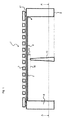
図1は1つの変換器素子1の1つの断面を示す。この変換器素子1は、1つの可動なメンブレン2および1つの固定されたバックプレート3を備える。メンブレン2とバックプレート3との間には、1つの電圧が印加されてよく、こうしてこのメンブレン2およびこのバックプレート3は1つのコンデンサを形成する。圧力変動の結果、このメンブレン2がバックプレート3に対して動くと、これよりこのコンデンサの静電容量が変化される。具体的には、音波は、このコンデンサの静電容量を変化させる圧力変動をもたらし得る。本変換器素子1は、圧力変動を電気信号に変換するように構成されている。具体的には、本変換器素子1は、1つの音響信号を1つの電気信号に変換することができる。 FIG. 1 shows one section of one transducer element 1. This transducer element 1 comprises one movable membrane 2 and one fixed back plate 3. A single voltage may be applied between the membrane 2 and the back plate 3, so that the membrane 2 and the back plate 3 form a single capacitor. As a result of the pressure fluctuation, when the membrane 2 moves relative to the back plate 3, the capacitance of the capacitor is changed. Specifically, sound waves can cause pressure fluctuations that change the capacitance of the capacitor. The transducer element 1 is configured to convert pressure fluctuations into electrical signals. Specifically, the transducer element 1 can convert one acoustic signal into one electrical signal.
変換器素子1は、1つのフロントキャビティと1つのバックキャビティとを形成する。このフロントキャビティは、本変換器素子1の外部環境と圧力的に連通するように適合している。これに応じて変換器素子1は、1つの音響入口開口部(不図示)を備え、この音響入口開口部を介してこのフロントキャビティが外部環境と圧力的に連通することができ、そして上記の音波または他の圧力波は、この音響入口開口部を介してメンブレン2に到達することができる。この変換器素子1のバックキャビティは、上記のフロントキャビティから音響的に分離されている基準キャビティである。この変換器素子1は、時間的に変化する、フロントキャビティにおける音圧と、バックキャビティにおける音圧との間の差を測定するのに適している。 The transducer element 1 forms one front cavity and one back cavity. This front cavity is adapted to be in pressure communication with the external environment of the transducer element 1. In response, the transducer element 1 comprises one acoustic inlet opening (not shown) through which the front cavity can be in pressure communication with the external environment and Sound waves or other pressure waves can reach the membrane 2 through this acoustic inlet opening. The back cavity of the transducer element 1 is a reference cavity that is acoustically separated from the front cavity. This transducer element 1 is suitable for measuring the difference between the sound pressure in the front cavity and the sound pressure in the back cavity, which changes over time.
さらに本変換器素子1は、フロントキャビティとバックキャビティとの間の静的な圧力平衡のための1つの通気開口部を備える。このためバックキャビティには、一定した変化しない圧力は存在しない。むしろこのバックキャビティにおける圧力は、この通気開口部を介してゆっくりと外部環境圧力に一致するようになる。 Furthermore, the transducer element 1 comprises one vent opening for static pressure balancing between the front and back cavities. For this reason, there is no constant unchanging pressure in the back cavity. Rather, the pressure in the back cavity slowly matches the external environmental pressure through the vent opening.
この通気開口部は、1つの大きな音響インピーダンスを備えている。以上により、音波はこの通気開口部を通ってバックキャビティに侵入することができない。 This vent opening has one large acoustic impedance. As described above, sound waves cannot enter the back cavity through this ventilation opening.
さらに、可動なメンブレン2は、1つの縁部4を備え、この縁部は、本変換器素子1の1つのフレーム5に固定されている。このメンブレン2の縁部4は、この縁部がバックプレート3に向かう方向またはこのバックプレート3から離れる方向においては動くことができないように固定されている。フレーム5に直接固定されていない、メンブレン2の内側領域6のみが、バックプレート3に向かう方向またはこのバックプレート3から離れる方向において可動となっている。変換器素子1のフレーム5は、シリコンから成っている。
Furthermore, the movable membrane 2 comprises one
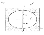
図2は、変換器素子1の、図1に示す線AA’に沿った1つの断面を示す。 FIG. 2 shows a cross section of the transducer element 1 along the line AA 'shown in FIG.
フレーム5の形状は、メンブレン2の形状に合わせ込まれている。このフレーム5は多数の部分に区分することができる。具体的には、このフレーム5は、1つの第1の部分7および1つの第2の部分8を備え、ここでこのフレーム5の第1および第2の部分7,8は互いに反対側にある。
The shape of the
さらに本変換器素子1は、1つの補強部材10を備える。この補強部材10は、フレーム5の第1の部分7をこのフレーム5の第2の部分8と結合している。この補強部材10は、フレーム5の高さよりいくらか小さな高さを有している。たとえば、この補強部材10の高さは、フレーム5の高さより5〜25μm小さくてよい。以上により、メンブレン2と補強部材10との間の最小距離16は、このメンブレン2が、この補強部材10上に直接着座しないようになっている。この補強部材10は、メンブレン2と反対側にあるフレーム5の面上にあるフレーム5の1つの下端9から、このメンブレン2から最小距離16だけ離間している上限位置15まで延伸している。
Furthermore, the converter element 1 includes one reinforcing
1つの第1の実施形態例によれば、補強部材10は帯形状となっている。この補強部材10の動作原理は、図2に示す断面を参照すれば明瞭であろう。
According to one first embodiment, the reinforcing
この補強部材10は、フレーム5の第1の部分7と、このフレーム5の第2の部分8とを結合している。この補強部材10は、メンブレン2に、より小さな力(複数)が印加されるように、そして特にこのメンブレン2に非対称な力(複数)が全く作用しないように、あるいは少なくともこのメンブレン2に非対称に作用する力(複数)の成分が大幅に低減されるように働く。
The reinforcing
非対称に作用する力は、具体的には以下に説明するようにして発生する。固定されたバックプレート3は、大きな張力を有している。これによりこの固定されたバックプレート3は、フレーム5に1つの力を印加し、この力は、このフレーム5を、このバックプレートが配設されているこのフレームの上端17へ引きつけられる。同時にこの力は、フレーム5がその下端9で引き離されるように作用する。フレーム5が上端17に引きつけられることにより、その縁部4がこのフレーム5の上端17に固定されている,メンブレン2も歪む。
The force acting asymmetrically is specifically generated as described below. The fixed back plate 3 has a large tension. As a result, the fixed back plate 3 applies one force to the
図2に示されている第1の実施形態例では、メンブレン2は楕円形状となっている。この楕円形状は、1つの主軸11と1つの副軸12とを規定し、この副軸は主軸11に対して直角となっており、かつこの主軸11より短くなっている。
In the first embodiment shown in FIG. 2, the membrane 2 has an elliptical shape. This elliptical shape defines one main shaft 11 and one
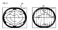
図3は、補強部材10の無い小判型メンブレン2a上に作用する機械的応力のシミュレーションを示す。この小判型メンブレン2aは、図2に示した楕円形状のメンブレン2と非常に良く似ている。左側の図は、x方向に作用する機械的応力を示し、右側の図は、y方向に作用する機械的応力を示す。ここでx方向は、このメンブレン2aの互いに最も離れた2つの点で規定されており、y方向は、このx方向に直角な方向である。楕円形状メンブレン2では、その主軸11がx方向に延伸しており、その副軸12がy方向に延伸している。
FIG. 3 shows a simulation of mechanical stress acting on the
メンブレン2aのx方向に沿って、1つの顕著に大きな機械的応力が発生することが、図3で明らかに見て取れる。このx方向に沿った、平均的な機械的応力は49.6MPaとなっている。このy方向に沿った、平均的な機械的応力は38.7MPaとなっている。全体として、補強部材10の無い小判型メンブレン2aにおけるx方向およびy方向での平均的な機械的応力の差は、10.9MPaとなっている。
It can be clearly seen in FIG. 3 that one significantly large mechanical stress is generated along the x direction of the
x方向とy方向とでの不均等な機械的応力の分布の理由は、フレーム5がx方向において、そのメンブレン2の大きな伸長のために、y方向におけるよりも弱いことにある。これにより、このメンブレン2は、固定されたバックプレート3からフレーム5へ印加される力により、x方向でy方向におけるよりも大きく歪む。
The reason for the uneven mechanical stress distribution in the x and y directions is that the
補強部材10は、フレーム5の第1および第2の部分7,8が、互いに1つの固定された距離で保持されるように用いられる。このフレーム5は、こうしてその下端9から、メンブレン2と補強部材10との間の最小距離に対応する高さまで、部分7,8が互いに固定された距離となるようにしっかりと保持される。この固定された距離は、補強部材10の長さによって予め与えられている。以上により、フレーム5がその上端で大きく動き得ることは抑えられる。これにより、より少ない力(複数)がメンブレン2,2aに印加される。フレーム5の機械的脆弱部への、ここに記載した補強部材10の配設によって、特にメンブレン2,2aに作用する力の非対称成分(複数)を低減することができる。
The reinforcing
図4は、補強部材10aの1つの第2の実施形態例を示す。ここではこの補強部材10aは、十字形状に形成されている。ここで補強部材10aは、フレーム5の第1および第2の部分7,8の他に、同様に、フレーム5の1つの第3の部分13を、この第3の部分13の反対側にある、このフレーム5の第4の部分14と結合している。この第3および第4の部分13,14も、互いに1つの固定された距離で保持されている。さらに、ここでもこの第3および第4の部分13,14は、補強部材10aによって、第1および第2の部分7,8に対して1つの規定された位置に保持されている。このフレーム5の第3および第4の部分13,14も、それぞれこのフレーム5の下端9からその上限位置15まで延伸しており、こうして補強部材10aとメンブレン2との間が最小距離16で空いている状態となっている。
FIG. 4 shows one second embodiment of the reinforcing
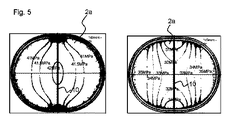
図5および6はそれぞれ、発生する機械的な力(複数)を示し、これらの力は小判型のメンブレン2aに作用する。ここで図5においては、第1の実施形態による帯形状の補強部材10が設けられており、図6においては、第2の実施形態による十字形状の補強部材10aが設けられている。図5および図6において、それぞれ左側の図には、x方向に作用する機械的応力が示されており、そして右側の図には、y方向に作用する機械的応力が示されている。
FIGS. 5 and 6 each show the mechanical force (s) generated and these forces act on the
メンブレン2aに作用する、機械的応力の発生が、補強部材10の無い実施形態例と比較して顕著に低減されていることが見て取れる。図5に示す帯形状の補強部材10を有する実施形態では、x方向に沿った平均的な機械的応力は、47.4MPaとなっている。y方向に沿った平均的な機械的応力は42.4MPaとなっている。全体として、帯形状の補強部材10を有する小判型のメンブレン2aにおけるx方向およびy方向での平均手的な機械的応力の差は、5.0MPaとなっている。
It can be seen that the generation of mechanical stress acting on the
図6に示す帯形状の補強部材10aを有する実施形態では、x方向に沿った平均的な機械的応力は、47.3MPaとなっている。y方向に沿った平均的な機械的応力は42.2MPaとなっている。全体として、十字形状の補強部材10aを有する小判型のメンブレン2aにおけるx方向およびy方向での平均的な機械的応力の差は、5.1MPaとなっている。
In the embodiment having the belt-shaped reinforcing
すなわち帯形状の補強部材10も、また十字形の補強部材10aも、x方向とy方向における平均的な機械的応力の差10.9Paを、5.0MPaあるいは5.1MPaへ顕著に低下することをもたらしている。以上のようにして、この帯形状の補強部材10あるいは十字形状の補強部材10aは、機械的応力がメンブレン2aにおいて均等に分布するように用いられる。
That is, both the belt-shaped reinforcing
ここで上記の第1の実施形態の補強部材10と第2の実施形態の補強部材10aとの間には実質的に殆ど改善が見られない。これは1つの方向においては別の方向におけるよりも顕著に剛性が低いというフレーム5の特別な形状に起因している。x軸に沿っては、このフレーム5は、ほぼ直線の部分を備え、この部分は比較的簡単に変形する。y軸に沿っては、このフレーム5は半円形状となっており、これにより比較的変形しにくい。これに対し別の形態で形成されているフレーム5あるいはメンブレン2では、補強部材10aの十字形状の構成は、帯形状の構成のものと比較して、この機械的な剛性を顕著に高めることができる。
Here, substantially no improvement is observed between the reinforcing
図7および図8は、変換器素子1の別の実施形態例を示す。図7および図8においては、これらのメンブレン2bは、それぞれ矩形に構成されている。図7においては、補強部材10は帯形状であり、図8においては補強部材10aは十字形状である。
7 and 8 show another example embodiment of the transducer element 1. 7 and 8, these membranes 2b are each configured in a rectangular shape. In FIG. 7, the reinforcing
さらにこの補強部材の他の形状も可能であり、たとえばこの補強部材は星形状であってよい。これらの選択された補強部材の形状は、常にメンブレンの形状に合わせられることになる。 Furthermore, other shapes of the reinforcing member are possible, for example, the reinforcing member may be star-shaped. The shape of these selected reinforcing members will always be matched to the shape of the membrane.
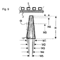
図9は、変換器素子1の一部を示し、この図を参照して、この変換器素子1の製造方法を概略的に説明する。 FIG. 9 shows a part of the converter element 1, and a method for manufacturing the converter element 1 will be schematically described with reference to this figure.
フレーム5および補強部材10は、1つの共通なエッチングステップで製造され、このエッチングステップでは、1つのシリコンウェーハ上に1つのマスクが取り付けられ、そして続いてこのシリコンウェーハの一部がエッチング除去され、こうしてこの変換器素子1のフロントキャビティが形成される。フレーム5および補強部材10は、こうしてこのシリコンウェーハからフォトリソグラフィーによって製造される。
The
こうしてこの補強部材10は、1つのシリコンブロックに1つの空洞を生成するこのエッチングステップで製造される。この方法は深掘り反応性イオンエッチング(DRIE)と呼ばれている。この方法は、プロセスパラメータの選択に依存して、この空洞の側壁で負の傾斜角αをもたらすことができ、この負の傾斜角は、補強部材10の側壁にも見られるものである。補強部材10の高さHは、このエッチング角αおよびこれに使用されるマスクの幅Wで調整される。
Thus, the reinforcing
図9には、補強部材10の様々な形態が示されている。幅W1,W2,およびW3では、この補強部材10はそれぞれ高さHを有している。幅W4あるいはW5の補強部材10では、高さはH4あるいはH5となっている。
FIG. 9 shows various forms of the reinforcing
使用されるマスクに依存して、そして上記のエッチング角αに依存して、この補強部材10は切り株状の頂部を有する楔形状かまたはメンブレン2に向かって尖状になっていてよい。この処理は、補強部材10がメンブレン2からの最小距離だけ離間されるように、調整される。さらにこのエッチングプロセスは、同じ高さを有する異なる幅の補強部材10を製造するために、エッチング角αが変化され得るように、変更することができる。
Depending on the mask used and depending on the etching angle α, this reinforcing
1 : 変換器素子
2,2a,2b : メンブレン
3 : バックプレート
4 : メンブレンの縁部
5 : フレーム
6 : メンブレンの内側領域
7 : 第1の部分
8 : 第2の部分
9 : フレームの下端
10,10a : 補強部材
11 : 主軸
12 : 副軸
13 : 第3の部分
14 : 第4の部分
15 : 上限位置
16 : 最小距離
17 : フレームの上端
1:
Claims (10)
1つの縁部(4)を有する、1つの可動なメンブレン(2,2a,2b)と、
前記メンブレン(2,2a,2b)の前記縁部(4)が固定されている1つのフレーム(5)と、
前記フレーム(5)の1つの第1の部分(7)と、当該第1の部分(7)の反対側にある、前記フレーム(5)の1つの第2の部分(8)とを互いに結合している、1つの補強部材(10)と、
を備えることを特徴とする変換器素子。 A transducer element (1) comprising:
One movable membrane (2, 2a, 2b) with one edge (4);
One frame (5) to which the edge (4) of the membrane (2, 2a, 2b) is fixed;
Combine one first part (7) of the frame (5) and one second part (8) of the frame (5) on the opposite side of the first part (7) One reinforcing member (10),
A transducer element comprising:
Applications Claiming Priority (3)
| Application Number | Priority Date | Filing Date | Title |
|---|---|---|---|
| DE102014108984.7A DE102014108984B4 (en) | 2014-06-26 | 2014-06-26 | transducer element |
| DE102014108984.7 | 2014-06-26 | ||
| PCT/EP2015/063206 WO2015197382A1 (en) | 2014-06-26 | 2015-06-12 | Transducer element and mems microphone |
Publications (2)
| Publication Number | Publication Date |
|---|---|
| JP2017525263A true JP2017525263A (en) | 2017-08-31 |
| JP6481833B2 JP6481833B2 (en) | 2019-03-13 |
Family
ID=53398087
Family Applications (1)
| Application Number | Title | Priority Date | Filing Date |
|---|---|---|---|
| JP2016575538A Expired - Fee Related JP6481833B2 (en) | 2014-06-26 | 2015-06-12 | Transducer element |
Country Status (4)
| Country | Link |
|---|---|
| US (1) | US10587961B2 (en) |
| JP (1) | JP6481833B2 (en) |
| DE (1) | DE102014108984B4 (en) |
| WO (1) | WO2015197382A1 (en) |
Cited By (1)
| Publication number | Priority date | Publication date | Assignee | Title |
|---|---|---|---|---|
| JP2019106616A (en) * | 2017-12-12 | 2019-06-27 | 新日本無線株式会社 | MEMS element |
Families Citing this family (2)
| Publication number | Priority date | Publication date | Assignee | Title |
|---|---|---|---|---|
| CN108346566B (en) * | 2017-01-22 | 2021-02-09 | 中芯国际集成电路制造(上海)有限公司 | Semiconductor device and method for manufacturing the same |
| CN108569672B (en) * | 2017-03-13 | 2020-08-25 | 中芯国际集成电路制造(上海)有限公司 | Microphone and method for manufacturing the same |
Citations (5)
| Publication number | Priority date | Publication date | Assignee | Title |
|---|---|---|---|---|
| JPS55130500U (en) * | 1979-03-09 | 1980-09-16 | ||
| JPS5693098U (en) * | 1979-12-15 | 1981-07-24 | ||
| JPS6234899U (en) * | 1985-08-19 | 1987-02-28 | ||
| WO2007004665A1 (en) * | 2005-07-06 | 2007-01-11 | Tokyo Electron Limited | Oscillatory wave detecting apparatus |
| US20110261979A1 (en) * | 2010-04-27 | 2011-10-27 | Bin Yang | Diaphragm and condenser microphone using same |
Family Cites Families (17)
| Publication number | Priority date | Publication date | Assignee | Title |
|---|---|---|---|---|
| JPS55130500A (en) | 1979-03-27 | 1980-10-09 | Naka Tech Lab | Lifting gear used for service car at height |
| US4418246A (en) | 1980-10-29 | 1983-11-29 | Tibbetts Industries, Inc. | Cell assembly for electret transducer |
| JPS6234899A (en) | 1985-08-09 | 1987-02-14 | Nippon Kokan Kk <Nkk> | Mooring-force reducing device for hull |
| EP0561566B1 (en) | 1992-03-18 | 1999-07-28 | Knowles Electronics, Inc. | Solid state condenser and microphone |
| US5490220A (en) | 1992-03-18 | 1996-02-06 | Knowles Electronics, Inc. | Solid state condenser and microphone devices |
| US5870482A (en) * | 1997-02-25 | 1999-02-09 | Knowles Electronics, Inc. | Miniature silicon condenser microphone |
| DE10030352A1 (en) * | 2000-06-21 | 2002-01-10 | Bosch Gmbh Robert | Micromechanical component, in particular sensor element, with a stabilized membrane and method for producing such a component |
| US7885423B2 (en) | 2005-04-25 | 2011-02-08 | Analog Devices, Inc. | Support apparatus for microphone diaphragm |
| US7825484B2 (en) | 2005-04-25 | 2010-11-02 | Analog Devices, Inc. | Micromachined microphone and multisensor and method for producing same |
| DE102005042664A1 (en) * | 2005-09-08 | 2007-03-15 | Robert Bosch Gmbh | Micromechanical sensor element and method for its production |
| DE102007020847B4 (en) * | 2007-05-02 | 2009-11-26 | Mundorf Eb Gmbh | Membrane arrangement for an electrodynamic sound transducer and loudspeaker with such a membrane arrangement |
| US8467559B2 (en) * | 2008-02-20 | 2013-06-18 | Shandong Gettop Acoustic Co., Ltd. | Silicon microphone without dedicated backplate |
| DE102008001185A1 (en) * | 2008-04-15 | 2009-10-29 | Robert Bosch Gmbh | Process for producing a micromechanical membrane structure with a fixed counter element |
| ITTO20130441A1 (en) * | 2013-05-30 | 2014-12-01 | St Microelectronics Srl | DETECTION STRUCTURE FOR A MEMS ACOUSTIC TRANSDUCER WITH IMPROVED DEFORMATION RESISTANCE |
| US9510103B2 (en) * | 2013-09-09 | 2016-11-29 | Audio Pixels Ltd. | Microelectromechanical apparatus for generating a physical effect |
| US8921957B1 (en) | 2013-10-11 | 2014-12-30 | Robert Bosch Gmbh | Method of improving MEMS microphone mechanical stability |
| JP6311375B2 (en) * | 2014-03-14 | 2018-04-18 | オムロン株式会社 | Capacitive transducer |
-
2014
- 2014-06-26 DE DE102014108984.7A patent/DE102014108984B4/en active Active
-
2015
- 2015-06-12 JP JP2016575538A patent/JP6481833B2/en not_active Expired - Fee Related
- 2015-06-12 US US15/319,890 patent/US10587961B2/en active Active
- 2015-06-12 WO PCT/EP2015/063206 patent/WO2015197382A1/en active Application Filing
Patent Citations (5)
| Publication number | Priority date | Publication date | Assignee | Title |
|---|---|---|---|---|
| JPS55130500U (en) * | 1979-03-09 | 1980-09-16 | ||
| JPS5693098U (en) * | 1979-12-15 | 1981-07-24 | ||
| JPS6234899U (en) * | 1985-08-19 | 1987-02-28 | ||
| WO2007004665A1 (en) * | 2005-07-06 | 2007-01-11 | Tokyo Electron Limited | Oscillatory wave detecting apparatus |
| US20110261979A1 (en) * | 2010-04-27 | 2011-10-27 | Bin Yang | Diaphragm and condenser microphone using same |
Non-Patent Citations (1)
| Title |
|---|
| 吉村 純一, 音のなんでもコーナー Q AND A, JPN6018029074, 20 November 2003 (2003-11-20), JP * |
Cited By (1)
| Publication number | Priority date | Publication date | Assignee | Title |
|---|---|---|---|---|
| JP2019106616A (en) * | 2017-12-12 | 2019-06-27 | 新日本無線株式会社 | MEMS element |
Also Published As
| Publication number | Publication date |
|---|---|
| US10587961B2 (en) | 2020-03-10 |
| US20170127188A1 (en) | 2017-05-04 |
| WO2015197382A1 (en) | 2015-12-30 |
| DE102014108984B4 (en) | 2017-04-06 |
| DE102014108984A1 (en) | 2015-12-31 |
| JP6481833B2 (en) | 2019-03-13 |
Similar Documents
| Publication | Publication Date | Title |
|---|---|---|
| US11265657B2 (en) | Piezoelectric MEMS microphone | |
| US20200100033A1 (en) | Micromechanical sound transducer | |
| EP2239961A1 (en) | Backplate for microphone | |
| US11212617B2 (en) | Piezoelectric MEMS microphone | |
| ITUA20163571A1 (en) | MEMS ACOUSTIC TRANSDUCER WITH INTERDIGATED ELECTRODES AND ITS MANUFACTURING PROCEDURE | |
| US20160007119A1 (en) | Diaphragm Stiffener | |
| US10638236B2 (en) | MEMS sound transducer, MEMS microphone and method for providing a MEMS sound transducer | |
| US20180002160A1 (en) | Mems device and process | |
| US11496820B2 (en) | MEMS device with quadrilateral trench and insert | |
| US10123129B2 (en) | MEMS device and process | |
| JP6481833B2 (en) | Transducer element | |
| Stoppel et al. | Novel membrane-less two-way MEMS loudspeaker based on piezoelectric dual-concentric actuators | |
| JP7349090B2 (en) | Piezoelectric element | |
| US20160150321A1 (en) | Micro phone and method of manufacturing the same | |
| US10524060B2 (en) | MEMS device having novel air flow restrictor | |
| US10244330B2 (en) | Lateral mode capacitive microphone with acceleration compensation | |
| Glacer et al. | Silicon microspeaker with out-of-plane displacement | |
| US20210099822A1 (en) | Capacitive microphone with two signal outputs that are additive inverse of each other | |
| US11546711B2 (en) | Process of fabricating lateral mode capacitive microphone | |
| US10715928B2 (en) | Capacitive microphone having capability of acceleration noise cancelation | |
| KR101893486B1 (en) | Rigid Backplate Structure Microphone and Method of Manufacturing the Same | |
| US20210337333A1 (en) | Process of fabricating capacitive microphone comprising moveable single conductor and stationary composite conductor | |
| JP6414605B2 (en) | MEMS microphone with improved sensitivity and method for manufacturing the same | |
| US20210314718A1 (en) | Process of fabricating lateral mode capacitive microphone including a capacitor plate with sandwich structure | |
| US20210099823A1 (en) | Capacitive microphone with two signal outputs that are additive inverse of each other |
Legal Events
| Date | Code | Title | Description |
|---|---|---|---|
| A131 | Notification of reasons for refusal |
Free format text: JAPANESE INTERMEDIATE CODE: A131 Effective date: 20171206 |
|
| A711 | Notification of change in applicant |
Free format text: JAPANESE INTERMEDIATE CODE: A711 Effective date: 20171212 |
|
| A521 | Request for written amendment filed |
Free format text: JAPANESE INTERMEDIATE CODE: A821 Effective date: 20171212 |
|
| A02 | Decision of refusal |
Free format text: JAPANESE INTERMEDIATE CODE: A02 Effective date: 20180801 |
|
| A521 | Request for written amendment filed |
Free format text: JAPANESE INTERMEDIATE CODE: A523 Effective date: 20181029 |
|
| A911 | Transfer to examiner for re-examination before appeal (zenchi) |
Free format text: JAPANESE INTERMEDIATE CODE: A911 Effective date: 20181107 |
|
| TRDD | Decision of grant or rejection written | ||
| A01 | Written decision to grant a patent or to grant a registration (utility model) |
Free format text: JAPANESE INTERMEDIATE CODE: A01 Effective date: 20190116 |
|
| A61 | First payment of annual fees (during grant procedure) |
Free format text: JAPANESE INTERMEDIATE CODE: A61 Effective date: 20190129 |
|
| R150 | Certificate of patent or registration of utility model |
Ref document number: 6481833 Country of ref document: JP Free format text: JAPANESE INTERMEDIATE CODE: R150 |
|
| LAPS | Cancellation because of no payment of annual fees |