JP2017523879A - Absorbent article with leg cuff - Google Patents
Absorbent article with leg cuff Download PDFInfo
- Publication number
- JP2017523879A JP2017523879A JP2017508545A JP2017508545A JP2017523879A JP 2017523879 A JP2017523879 A JP 2017523879A JP 2017508545 A JP2017508545 A JP 2017508545A JP 2017508545 A JP2017508545 A JP 2017508545A JP 2017523879 A JP2017523879 A JP 2017523879A
- Authority
- JP
- Japan
- Prior art keywords
- cuff
- elastic element
- article
- elastic
- layer
- Prior art date
- Legal status (The legal status is an assumption and is not a legal conclusion. Google has not performed a legal analysis and makes no representation as to the accuracy of the status listed.)
- Ceased
Links
Images


Classifications
-
- A—HUMAN NECESSITIES
- A61—MEDICAL OR VETERINARY SCIENCE; HYGIENE
- A61F—FILTERS IMPLANTABLE INTO BLOOD VESSELS; PROSTHESES; DEVICES PROVIDING PATENCY TO, OR PREVENTING COLLAPSING OF, TUBULAR STRUCTURES OF THE BODY, e.g. STENTS; ORTHOPAEDIC, NURSING OR CONTRACEPTIVE DEVICES; FOMENTATION; TREATMENT OR PROTECTION OF EYES OR EARS; BANDAGES, DRESSINGS OR ABSORBENT PADS; FIRST-AID KITS
- A61F13/00—Bandages or dressings; Absorbent pads
- A61F13/15—Absorbent pads, e.g. sanitary towels, swabs or tampons for external or internal application to the body; Supporting or fastening means therefor; Tampon applicators
- A61F13/45—Absorbent pads, e.g. sanitary towels, swabs or tampons for external or internal application to the body; Supporting or fastening means therefor; Tampon applicators characterised by the shape
- A61F13/49—Absorbent articles specially adapted to be worn around the waist, e.g. diapers
- A61F13/494—Absorbent articles specially adapted to be worn around the waist, e.g. diapers characterised by edge leakage prevention means
-
- A—HUMAN NECESSITIES
- A61—MEDICAL OR VETERINARY SCIENCE; HYGIENE
- A61F—FILTERS IMPLANTABLE INTO BLOOD VESSELS; PROSTHESES; DEVICES PROVIDING PATENCY TO, OR PREVENTING COLLAPSING OF, TUBULAR STRUCTURES OF THE BODY, e.g. STENTS; ORTHOPAEDIC, NURSING OR CONTRACEPTIVE DEVICES; FOMENTATION; TREATMENT OR PROTECTION OF EYES OR EARS; BANDAGES, DRESSINGS OR ABSORBENT PADS; FIRST-AID KITS
- A61F13/00—Bandages or dressings; Absorbent pads
- A61F13/15—Absorbent pads, e.g. sanitary towels, swabs or tampons for external or internal application to the body; Supporting or fastening means therefor; Tampon applicators
- A61F13/45—Absorbent pads, e.g. sanitary towels, swabs or tampons for external or internal application to the body; Supporting or fastening means therefor; Tampon applicators characterised by the shape
- A61F13/49—Absorbent articles specially adapted to be worn around the waist, e.g. diapers
- A61F13/49007—Form-fitting, self-adjusting disposable diapers
- A61F13/49009—Form-fitting, self-adjusting disposable diapers with elastic means
- A61F13/4902—Form-fitting, self-adjusting disposable diapers with elastic means characterised by the elastic material
-
- A—HUMAN NECESSITIES
- A61—MEDICAL OR VETERINARY SCIENCE; HYGIENE
- A61F—FILTERS IMPLANTABLE INTO BLOOD VESSELS; PROSTHESES; DEVICES PROVIDING PATENCY TO, OR PREVENTING COLLAPSING OF, TUBULAR STRUCTURES OF THE BODY, e.g. STENTS; ORTHOPAEDIC, NURSING OR CONTRACEPTIVE DEVICES; FOMENTATION; TREATMENT OR PROTECTION OF EYES OR EARS; BANDAGES, DRESSINGS OR ABSORBENT PADS; FIRST-AID KITS
- A61F13/00—Bandages or dressings; Absorbent pads
- A61F13/15—Absorbent pads, e.g. sanitary towels, swabs or tampons for external or internal application to the body; Supporting or fastening means therefor; Tampon applicators
- A61F13/45—Absorbent pads, e.g. sanitary towels, swabs or tampons for external or internal application to the body; Supporting or fastening means therefor; Tampon applicators characterised by the shape
- A61F13/49—Absorbent articles specially adapted to be worn around the waist, e.g. diapers
- A61F13/494—Absorbent articles specially adapted to be worn around the waist, e.g. diapers characterised by edge leakage prevention means
- A61F13/49406—Absorbent articles specially adapted to be worn around the waist, e.g. diapers characterised by edge leakage prevention means the edge leakage prevention means being at the crotch region
- A61F13/49413—Absorbent articles specially adapted to be worn around the waist, e.g. diapers characterised by edge leakage prevention means the edge leakage prevention means being at the crotch region the edge leakage prevention means being an upstanding barrier
- A61F13/4942—Absorbent articles specially adapted to be worn around the waist, e.g. diapers characterised by edge leakage prevention means the edge leakage prevention means being at the crotch region the edge leakage prevention means being an upstanding barrier the barrier not being integral with the top- or back-sheet
-
- A—HUMAN NECESSITIES
- A61—MEDICAL OR VETERINARY SCIENCE; HYGIENE
- A61F—FILTERS IMPLANTABLE INTO BLOOD VESSELS; PROSTHESES; DEVICES PROVIDING PATENCY TO, OR PREVENTING COLLAPSING OF, TUBULAR STRUCTURES OF THE BODY, e.g. STENTS; ORTHOPAEDIC, NURSING OR CONTRACEPTIVE DEVICES; FOMENTATION; TREATMENT OR PROTECTION OF EYES OR EARS; BANDAGES, DRESSINGS OR ABSORBENT PADS; FIRST-AID KITS
- A61F13/00—Bandages or dressings; Absorbent pads
- A61F13/15—Absorbent pads, e.g. sanitary towels, swabs or tampons for external or internal application to the body; Supporting or fastening means therefor; Tampon applicators
- A61F13/45—Absorbent pads, e.g. sanitary towels, swabs or tampons for external or internal application to the body; Supporting or fastening means therefor; Tampon applicators characterised by the shape
- A61F13/49—Absorbent articles specially adapted to be worn around the waist, e.g. diapers
- A61F13/496—Absorbent articles specially adapted to be worn around the waist, e.g. diapers in the form of pants or briefs
-
- A—HUMAN NECESSITIES
- A61—MEDICAL OR VETERINARY SCIENCE; HYGIENE
- A61F—FILTERS IMPLANTABLE INTO BLOOD VESSELS; PROSTHESES; DEVICES PROVIDING PATENCY TO, OR PREVENTING COLLAPSING OF, TUBULAR STRUCTURES OF THE BODY, e.g. STENTS; ORTHOPAEDIC, NURSING OR CONTRACEPTIVE DEVICES; FOMENTATION; TREATMENT OR PROTECTION OF EYES OR EARS; BANDAGES, DRESSINGS OR ABSORBENT PADS; FIRST-AID KITS
- A61F13/00—Bandages or dressings; Absorbent pads
- A61F13/15—Absorbent pads, e.g. sanitary towels, swabs or tampons for external or internal application to the body; Supporting or fastening means therefor; Tampon applicators
- A61F13/15203—Properties of the article, e.g. stiffness or absorbency
- A61F2013/15284—Properties of the article, e.g. stiffness or absorbency characterized by quantifiable properties
- A61F2013/15292—Resistance, i.e. modulus or strength
-
- A—HUMAN NECESSITIES
- A61—MEDICAL OR VETERINARY SCIENCE; HYGIENE
- A61F—FILTERS IMPLANTABLE INTO BLOOD VESSELS; PROSTHESES; DEVICES PROVIDING PATENCY TO, OR PREVENTING COLLAPSING OF, TUBULAR STRUCTURES OF THE BODY, e.g. STENTS; ORTHOPAEDIC, NURSING OR CONTRACEPTIVE DEVICES; FOMENTATION; TREATMENT OR PROTECTION OF EYES OR EARS; BANDAGES, DRESSINGS OR ABSORBENT PADS; FIRST-AID KITS
- A61F13/00—Bandages or dressings; Absorbent pads
- A61F13/15—Absorbent pads, e.g. sanitary towels, swabs or tampons for external or internal application to the body; Supporting or fastening means therefor; Tampon applicators
- A61F13/15203—Properties of the article, e.g. stiffness or absorbency
- A61F2013/15284—Properties of the article, e.g. stiffness or absorbency characterized by quantifiable properties
- A61F2013/15422—Density
-
- A—HUMAN NECESSITIES
- A61—MEDICAL OR VETERINARY SCIENCE; HYGIENE
- A61F—FILTERS IMPLANTABLE INTO BLOOD VESSELS; PROSTHESES; DEVICES PROVIDING PATENCY TO, OR PREVENTING COLLAPSING OF, TUBULAR STRUCTURES OF THE BODY, e.g. STENTS; ORTHOPAEDIC, NURSING OR CONTRACEPTIVE DEVICES; FOMENTATION; TREATMENT OR PROTECTION OF EYES OR EARS; BANDAGES, DRESSINGS OR ABSORBENT PADS; FIRST-AID KITS
- A61F13/00—Bandages or dressings; Absorbent pads
- A61F13/15—Absorbent pads, e.g. sanitary towels, swabs or tampons for external or internal application to the body; Supporting or fastening means therefor; Tampon applicators
- A61F13/15203—Properties of the article, e.g. stiffness or absorbency
- A61F2013/15284—Properties of the article, e.g. stiffness or absorbency characterized by quantifiable properties
- A61F2013/15544—Permeability
- A61F2013/15552—Air permeability
-
- A—HUMAN NECESSITIES
- A61—MEDICAL OR VETERINARY SCIENCE; HYGIENE
- A61F—FILTERS IMPLANTABLE INTO BLOOD VESSELS; PROSTHESES; DEVICES PROVIDING PATENCY TO, OR PREVENTING COLLAPSING OF, TUBULAR STRUCTURES OF THE BODY, e.g. STENTS; ORTHOPAEDIC, NURSING OR CONTRACEPTIVE DEVICES; FOMENTATION; TREATMENT OR PROTECTION OF EYES OR EARS; BANDAGES, DRESSINGS OR ABSORBENT PADS; FIRST-AID KITS
- A61F13/00—Bandages or dressings; Absorbent pads
- A61F13/15—Absorbent pads, e.g. sanitary towels, swabs or tampons for external or internal application to the body; Supporting or fastening means therefor; Tampon applicators
- A61F13/15203—Properties of the article, e.g. stiffness or absorbency
- A61F2013/15284—Properties of the article, e.g. stiffness or absorbency characterized by quantifiable properties
- A61F2013/15544—Permeability
- A61F2013/1556—Water permeability
-
- A—HUMAN NECESSITIES
- A61—MEDICAL OR VETERINARY SCIENCE; HYGIENE
- A61F—FILTERS IMPLANTABLE INTO BLOOD VESSELS; PROSTHESES; DEVICES PROVIDING PATENCY TO, OR PREVENTING COLLAPSING OF, TUBULAR STRUCTURES OF THE BODY, e.g. STENTS; ORTHOPAEDIC, NURSING OR CONTRACEPTIVE DEVICES; FOMENTATION; TREATMENT OR PROTECTION OF EYES OR EARS; BANDAGES, DRESSINGS OR ABSORBENT PADS; FIRST-AID KITS
- A61F13/00—Bandages or dressings; Absorbent pads
- A61F13/15—Absorbent pads, e.g. sanitary towels, swabs or tampons for external or internal application to the body; Supporting or fastening means therefor; Tampon applicators
- A61F13/45—Absorbent pads, e.g. sanitary towels, swabs or tampons for external or internal application to the body; Supporting or fastening means therefor; Tampon applicators characterised by the shape
- A61F13/49—Absorbent articles specially adapted to be worn around the waist, e.g. diapers
- A61F13/49007—Form-fitting, self-adjusting disposable diapers
- A61F13/49009—Form-fitting, self-adjusting disposable diapers with elastic means
- A61F13/4902—Form-fitting, self-adjusting disposable diapers with elastic means characterised by the elastic material
- A61F2013/49031—Form-fitting, self-adjusting disposable diapers with elastic means characterised by the elastic material being elastic in longitudinal direction
-
- A—HUMAN NECESSITIES
- A61—MEDICAL OR VETERINARY SCIENCE; HYGIENE
- A61F—FILTERS IMPLANTABLE INTO BLOOD VESSELS; PROSTHESES; DEVICES PROVIDING PATENCY TO, OR PREVENTING COLLAPSING OF, TUBULAR STRUCTURES OF THE BODY, e.g. STENTS; ORTHOPAEDIC, NURSING OR CONTRACEPTIVE DEVICES; FOMENTATION; TREATMENT OR PROTECTION OF EYES OR EARS; BANDAGES, DRESSINGS OR ABSORBENT PADS; FIRST-AID KITS
- A61F13/00—Bandages or dressings; Absorbent pads
- A61F13/15—Absorbent pads, e.g. sanitary towels, swabs or tampons for external or internal application to the body; Supporting or fastening means therefor; Tampon applicators
- A61F13/45—Absorbent pads, e.g. sanitary towels, swabs or tampons for external or internal application to the body; Supporting or fastening means therefor; Tampon applicators characterised by the shape
- A61F13/49—Absorbent articles specially adapted to be worn around the waist, e.g. diapers
- A61F13/49007—Form-fitting, self-adjusting disposable diapers
- A61F13/49009—Form-fitting, self-adjusting disposable diapers with elastic means
- A61F2013/49041—Form-fitting, self-adjusting disposable diapers with elastic means having a specific location other than covered by groups A61F13/49011 - A61F13/49019
-
- A—HUMAN NECESSITIES
- A61—MEDICAL OR VETERINARY SCIENCE; HYGIENE
- A61F—FILTERS IMPLANTABLE INTO BLOOD VESSELS; PROSTHESES; DEVICES PROVIDING PATENCY TO, OR PREVENTING COLLAPSING OF, TUBULAR STRUCTURES OF THE BODY, e.g. STENTS; ORTHOPAEDIC, NURSING OR CONTRACEPTIVE DEVICES; FOMENTATION; TREATMENT OR PROTECTION OF EYES OR EARS; BANDAGES, DRESSINGS OR ABSORBENT PADS; FIRST-AID KITS
- A61F13/00—Bandages or dressings; Absorbent pads
- A61F13/15—Absorbent pads, e.g. sanitary towels, swabs or tampons for external or internal application to the body; Supporting or fastening means therefor; Tampon applicators
- A61F13/45—Absorbent pads, e.g. sanitary towels, swabs or tampons for external or internal application to the body; Supporting or fastening means therefor; Tampon applicators characterised by the shape
- A61F13/49—Absorbent articles specially adapted to be worn around the waist, e.g. diapers
- A61F2013/49088—Absorbent articles specially adapted to be worn around the waist, e.g. diapers characterized by the leg opening
- A61F2013/49092—Absorbent articles specially adapted to be worn around the waist, e.g. diapers characterized by the leg opening comprising leg cuffs
- A61F2013/49093—Absorbent articles specially adapted to be worn around the waist, e.g. diapers characterized by the leg opening comprising leg cuffs having multiple barriers
-
- A—HUMAN NECESSITIES
- A61—MEDICAL OR VETERINARY SCIENCE; HYGIENE
- A61F—FILTERS IMPLANTABLE INTO BLOOD VESSELS; PROSTHESES; DEVICES PROVIDING PATENCY TO, OR PREVENTING COLLAPSING OF, TUBULAR STRUCTURES OF THE BODY, e.g. STENTS; ORTHOPAEDIC, NURSING OR CONTRACEPTIVE DEVICES; FOMENTATION; TREATMENT OR PROTECTION OF EYES OR EARS; BANDAGES, DRESSINGS OR ABSORBENT PADS; FIRST-AID KITS
- A61F13/00—Bandages or dressings; Absorbent pads
- A61F13/15—Absorbent pads, e.g. sanitary towels, swabs or tampons for external or internal application to the body; Supporting or fastening means therefor; Tampon applicators
- A61F13/45—Absorbent pads, e.g. sanitary towels, swabs or tampons for external or internal application to the body; Supporting or fastening means therefor; Tampon applicators characterised by the shape
- A61F13/49—Absorbent articles specially adapted to be worn around the waist, e.g. diapers
- A61F13/494—Absorbent articles specially adapted to be worn around the waist, e.g. diapers characterised by edge leakage prevention means
- A61F2013/4948—Absorbent articles specially adapted to be worn around the waist, e.g. diapers characterised by edge leakage prevention means the edge leakage prevention means being elastic
Abstract
1)透水性トップシート(58)と、2)不透水性バックシート(60)と、3)吸収性コア(62)と、4)外側カバー層(42)と、5)脚部ガスケット機能を提供する一対の外側カフ(66)であって、それぞれの外側カフは、a)横方向において吸収性コアとバックシートの長手方向側縁部との間に位置する、カフ封止部(76)と、b)横方向においてバックシートの長手方向側縁部の内側に位置しているが、横方向においてカフ封止部から3mmより内側には位置していない、第1のカフ弾性要素(72)と、c)横方向においてバックシートの長手方向側縁部の外側に位置し、第2のカフ弾性要素のそれぞれの弾性体の張力は、第1のカフ弾性要素のいずれの弾性体の張力に対しても70%以下となる、第2のカフ弾性要素(74)と、d)第1のカフ弾性要素と第2のカフ弾性要素との間に位置するカフギャップ(70)であって、前記カフギャップは、少なくとも3mmの横方向幅を有する、カフギャップと、e)カフ外縁部(78)であって、横方向において第2のカフ弾性要素の外側に位置し、少なくとも5mmの横方向幅を有する、カフ外縁部と、を含む、一対の外側カフと、を含み、カフ封止部(76)は、カフ封止部が位置している所での、物品の厚さ方向に存在する材料の全てを結合する、吸収性物品(20)が開示される。1) water-permeable top sheet (58), 2) water-impermeable back sheet (60), 3) absorbent core (62), 4) outer cover layer (42), and 5) leg gasket function. A pair of outer cuffs (66) to be provided, each outer cuff a) located laterally between the absorbent core and the longitudinal side edge of the backsheet, cuff seal (76) And b) a first cuff elastic element (72) which is located inside the longitudinal side edge of the backsheet in the lateral direction but not located more than 3 mm from the cuff sealing portion in the lateral direction. ) And c) located outside the longitudinal side edge of the backsheet in the lateral direction, and the tension of each elastic body of the second cuff elastic element is the tension of any elastic body of the first cuff elastic element The second cuff elastic element (70% or less of 4) and d) a cuff gap (70) located between the first cuff elastic element and the second cuff elastic element, said cuff gap having a lateral width of at least 3 mm. And e) a cuff outer edge (78), located laterally outside the second cuff elastic element in the lateral direction and having a lateral width of at least 5 mm and a pair of outer cuffs An absorbent article (20) is disclosed wherein the cuff seal (76) combines all of the material present in the thickness direction of the article where the cuff seal is located. Is done.
Description
本発明は、柔軟性を向上させたレッグカフを有するおむつなどの吸収性物品に関する。 The present invention relates to an absorbent article such as a diaper having a leg cuff with improved flexibility.
おむつなどの吸収性物品により、尿及び/又は他の身体排出物の受け入れ、及び収容に関する便益が得られることが、ずっと以前から知られている。排出物を有効に収容するためには、物品が着用者のウエスト及び脚部の周りにぴったりとフィットする必要がある。吸収性物品は、トップシートと、バックシートと、吸収性コアと、を含む吸収性本体を有することが知られている。 It has long been known that absorbent articles such as diapers provide the benefits of receiving and containing urine and / or other body excretion. In order to effectively contain the effluent, the article needs to fit snugly around the wearer's waist and legs. It is known that an absorbent article has an absorbent main body including a top sheet, a back sheet, and an absorbent core.
現在のおむつの設計では、身体排出物の漏れを防ぐための内側レッグカフと、この内側レッグカフを通じて排出物が見えるのを最小限にするための内側レッグカフを覆うカバーとなり、かつ、身体排出物が内側レッグカフから滲み出た場合に、それを捕える副次的な手段を提供する外側レッグカフの使用を伴うことが多い。内側レッグカフは、疎水性不織布を使用して作製される場合があり、吸収性物品の身体に面する表面上に配置されたり、又はフィルムバックシート層の身体に面する表面に接続される場合がある。内側レッグカフは、身体排出物が、物品の側部から外に通過するのを防止する実質的に液体不透過性の層であってよく、かつ、外部の空気が皮膚に到達して、皮膚水分量を健常な水準に保つように高い通気性を有していてよい。外側レッグカフは外側レッグ弾性ストランドを含み、これは収縮力及びギャザーを形成し、カフ材料とバックシート材料の間に挟まれ得る。現在のおむつ類の多くにおいては、外側レッグカフは、製造中に溶融した接着剤が物品の衣類に面する表面へとカフを通り抜けていくことを防ぐと同時に、材料の切断、追跡、移送(transfer)及び組み立て時の製造公差を確保するため、バックシートのポリマーフィルム層を含む。これらの問題を防ぐために、一般的にポリマー製のフィルムが用いられているが、取り扱い時にプラスチックのような触感を生んだり、紙のような音を発したりすることがある。こういった感覚的な特徴は、安く、又は低品質なおむつを連想させるものである。 The current diaper design provides an inner leg cuff to prevent leakage of body discharge and a cover that covers the inner leg cuff to minimize the visibility of the discharge through the inner leg cuff, and the body discharge is on the inner side. Often involves the use of an outer leg cuff that provides a secondary means of catching the leg cuff as it oozes. The inner leg cuff may be made using a hydrophobic nonwoven and may be placed on the body facing surface of the absorbent article or connected to the body facing surface of the film backsheet layer. is there. The inner leg cuff may be a substantially liquid impervious layer that prevents body exudates from passing out of the side of the article, and external air reaches the skin and causes skin moisture. It may have high breathability so as to keep the amount at a healthy level. The outer leg cuff includes outer leg elastic strands that form shrinkage and gathers and can be sandwiched between the cuff material and the backsheet material. In many of today's diapers, the outer leg cuff prevents the molten adhesive from passing through the cuff to the garment facing surface of the article while simultaneously cutting, tracking and transferring the material. ) And a polymer film layer of the backsheet is included to ensure manufacturing tolerance during assembly. In order to prevent these problems, a film made of a polymer is generally used. However, a tactile sensation like a plastic may be produced during handling or a sound like a paper may be emitted. These sensory features are reminiscent of cheap or low quality diapers.
前述の内容を踏まえると、漏れ防止性能を維持しつつも、触覚が向上し、かつ柔軟性が知覚されるレッグカフを有する吸収性物品に対する需要がある。更に、そのような着用可能物品を、信頼性が高く、かつ経済的な方法で製造することに対しても需要がある。 In light of the foregoing, there is a need for an absorbent article having a leg cuff that improves tactile sensation and perceives flexibility while maintaining leakage prevention performance. Further, there is a need for producing such wearable articles in a reliable and economical manner.
本発明は、肌に面する側と、衣類に面する側と、長手方向軸線と、横方向軸線と、を有する、吸収性物品であって、該吸収性物品は、
1)長手方向及び横方向に延在する透水性トップシートと、
2)長手方向及び横方向に延在し、かつ一対の長手方向側縁部を有する不透水性バックシートと、
3)トップシートとバックシートとの間に配置された吸収性コアであって、バックシートは、長手方向及び横方向の両方において吸収性コアを越えて延在する、吸収性コアと、
4)バックシートの衣類に面する側に配置された外側カバー層であって、外側カバー層は、少なくともバックシートと同一の広がりを持つ、外側カバー層と、
5)脚部ガスケット機能を提供する一対の外側カフであって、それぞれの外側カフは、
a)長手方向に延在するように配置されたカフ封止部であって、カフ封止部は、横方向において吸収性コアとバックシートの長手方向側縁部との間に位置する、カフ封止部と、
b)長手方向に延在するように配置された少なくとも1つの弾性体を含む第1のカフ弾性要素であって、第1のカフ弾性要素は、横方向においてバックシートの長手方向側縁部の内側に位置しているが、横方向においてカフ封止部から3mmより内側には位置していない、第1のカフ弾性要素と、
c)長手方向に延在するように配置された少なくとも1つの弾性体を含む第2のカフ弾性要素であって、第2のカフ弾性要素は、横方向においてバックシートの長手方向側縁部の外側に位置し、第2のカフ弾性要素のそれぞれの弾性体の張力は、第1のカフ弾性要素のいずれの弾性体の張力に対しても70%以下となる、第2のカフ弾性要素と、
d)第1のカフ弾性要素と第2のカフ弾性要素との間に位置するカフギャップであって、カフギャップは、少なくとも3mmの横方向幅を有する、カフギャップと、
e)長手方向に延在するように配置されたカフ外縁部であって、カフ外縁部は、横方向において第2のカフ弾性要素の外側に位置し、カフ外縁部は、少なくとも5mmの横方向幅を有する、カフ外縁部と、を含む、一対の外側カフと、を含み、
カフ封止部は、カフ封止部が位置している所での、物品の厚さ方向に存在する材料の全てを結合する、吸収性物品。
The present invention is an absorbent article having a skin-facing side, a garment-facing side, a longitudinal axis, and a transverse axis, the absorbent article comprising:
1) a water-permeable topsheet extending in the longitudinal and lateral directions;
2) an impervious backsheet extending in the longitudinal and lateral directions and having a pair of longitudinal side edges;
3) an absorbent core disposed between the topsheet and the backsheet, the backsheet extending beyond the absorbent core in both the longitudinal direction and the transverse direction;
4) An outer cover layer disposed on the garment facing side of the backsheet, the outer cover layer having at least the same extent as the backsheet;
5) A pair of outer cuffs providing leg gasket functions, each outer cuff being
a) A cuff sealing portion disposed so as to extend in the longitudinal direction, the cuff sealing portion being located between the absorbent core and the longitudinal side edge of the back sheet in the lateral direction. A sealing part;
b) a first cuff elastic element including at least one elastic body arranged so as to extend in the longitudinal direction, the first cuff elastic element in the lateral direction of the longitudinal side edge of the backsheet A first cuff elastic element which is located inside but not located inwardly from the cuff seal in the transverse direction by 3 mm;
c) a second cuff elastic element comprising at least one elastic body arranged to extend in the longitudinal direction, wherein the second cuff elastic element in the lateral direction of the longitudinal side edge of the backsheet A second cuff elastic element located on the outer side, wherein the tension of each elastic body of the second cuff elastic element is 70% or less with respect to the tension of any elastic body of the first cuff elastic element; ,
d) a cuff gap located between the first cuff elastic element and the second cuff elastic element, the cuff gap having a lateral width of at least 3 mm;
e) a cuff outer edge arranged to extend in the longitudinal direction, the cuff outer edge being laterally located outside the second cuff elastic element, the cuff outer edge being a lateral direction of at least 5 mm A pair of outer cuffs including a cuff outer edge having a width;
The cuff seal is an absorbent article that binds all of the material present in the thickness direction of the article where the cuff seal is located.
用語の定義
本明細書で使用するとき、以下の用語は下記で指定される意味を有するものとする。
吸収性物品に関連しての「使い捨て」は、吸収性物品が、洗濯するか、又は別の方法で吸収性物品として復元若しくは再利用することが一般的に意図されない(即ち、単回の使用の後で廃棄する、好ましくはリサイクル、堆肥化、あるいは環境に適合する様態で廃棄することが意図される)ことを意味する。
Definitions of Terms As used herein, the following terms shall have the meanings specified below.
“Disposable” in connection with an absorbent article is generally not intended for the absorbent article to be laundered or otherwise restored or reused as an absorbent article (ie, single use). Is intended to be disposed after, preferably recycled, composted or environmentally compatible).
「吸収性物品」とは、身体排出物を吸収及び収容するデバイスを指し、より詳細には、着用者の身体に接して、又は近接して置かれて、身体から排出される様々な排出物を吸収し、収容するデバイスを指す。吸収性物品の例としては、おむつ、トレーニングパンツ、プルオンパンツ式おむつ(即ち、米国特許第6,120,487号に示されているような予め形成されたウエスト開口部及び脚部開口部を有するおむつ)、再締結可能なおむつ若しくはパンツ型おむつ、失禁用ブリーフ及び下着、おむつホルダ及びライナー、パンティライナーなどの女性用衛生衣類、吸収性挿入物などが挙げられる。 “Absorbent article” refers to a device that absorbs and contains body discharges, and more particularly various discharges that are discharged from the body placed on or in close proximity to the wearer's body. Refers to a device that absorbs and contains. Examples of absorbent articles include diapers, training pants, pull-on pants-type diapers (i.e., pre-formed waist openings and leg openings as shown in U.S. Pat. No. 6,120,487). Diapers), refastenable diapers or pant diapers, incontinence briefs and underwear, diaper holders and liners, feminine hygiene garments such as panty liners, absorbent inserts and the like.
「パンツ」は、予め成形されたウエスト部及び脚部開口部を有する使い捨て吸収性物品を指す。パンツは、着用者の両脚を脚部開口部に入れ、パンツを滑らせて、着用者の胴体下部の周りの位置に至らせることにより身に付けることができる。また、パンツは、通常、「閉鎖型おむつ」、「締結済おむつ」、「プルオン式おむつ」、「トレーニングパンツ」及び「おむつパンツ」とも呼ばれる。 “Pants” refers to a disposable absorbent article having a pre-formed waist and leg openings. The pants can be worn by putting the wearer's legs into the leg openings and sliding the pants to a position around the wearer's lower torso. The pants are also commonly referred to as “closed diapers”, “fastened diapers”, “pull-on diapers”, “training pants”, and “diaper pants”.
「長手方向の」とは、物品の一方のウエスト縁部から反対側のウエスト縁部に向かって実質的に垂直で、かつ物品の最大直線寸法にほぼ平行な方向を指す。 “Longitudinal” refers to a direction that is substantially perpendicular from one waist edge to the opposite waist edge of the article and substantially parallel to the maximum linear dimension of the article.
「横方向の」とは、長手方向に対して垂直な方向を指す。 “Lateral” refers to a direction perpendicular to the longitudinal direction.
「内側」及び「外側」とは、それぞれ、構造体の長手方向中心線又は横方向中心線から相対的に近い又は遠い、要素の位置を指す。 “Inside” and “outside” refer to the position of an element relatively near or far from the longitudinal or lateral centerline of the structure, respectively.
「身体に面する」及び「衣類に面する」とは、それぞれ、要素若しくは要素の面、又は要素の群の相対位置を指す。「身体に面する」とは、要素又は面が他の要素又は面よりも、着用時に着用者により近いことを意味する。「衣類に面する」とは、要素又は面が他の要素又は面より、着用時に着用者からより遠くに離れていることを意味する(即ち、要素又は面が、使い捨て吸収性物品の上に着用され得る着用者の衣類に近接する)。 “Body facing” and “clothing facing” refer to the relative position of an element or element face or group of elements, respectively. “Body facing” means that an element or surface is closer to the wearer when worn than other elements or surfaces. “Clothing facing” means that an element or surface is farther away from the wearer when worn than other elements or surfaces (ie, the element or surface is on a disposable absorbent article). Proximity to the wearer's clothing that can be worn).
「配置される」とは、要素がある特定の場所又は位置に設けられていることを指す。 “Arranged” means that an element is provided at a certain place or position.
「接合された」とは、要素が他の要素に直接的に取り付けられることによって、要素が別の要素に直接固定されている形態、及び要素が1つ又は複数の中間の部材に取り付けられ、その1つ又は複数の中間部材が他の要素に取り付けられることによって、要素が別の要素に間接的に固定されている形態を指す。 “Jointed” means that an element is directly attached to another element by attaching the element directly to another element, and the element is attached to one or more intermediate members, The element is indirectly fixed to another element by attaching the one or more intermediate members to the other element.
「フィルム」とは、材料の長さ及び幅が材料の厚さを大きく上回るシート状材料を指す。通常、フィルムは約0.5mm以下の厚さを有する。 “Film” refers to a sheet-like material in which the length and width of the material greatly exceeds the thickness of the material. Usually, the film has a thickness of about 0.5 mm or less.
「透水性」及び「不透水性」は、使い捨て吸収性物品の意図された使用に関連する材料の浸透性を指す。具体的には、用語「透水性」は、液体の水、尿又は合成尿が押し付け圧力がない状態で、その厚さを通過できる孔、開口部及び/又は相互に接続された空隙を有する層又は層構造体を指す。逆に、用語「不透水性」は、液体の水、尿又は合成尿が(重力などの自然の力とは別の)押し付け圧力がない状態では、その厚さを通過できない層又は層構造体を指す。この定義により不透水性の層又は層状構造体は、水蒸気に対して透過性(即ち、「蒸気透過性」)であってもよい。 “Water-permeable” and “water-impermeable” refer to the permeability of materials associated with the intended use of the disposable absorbent article. Specifically, the term “water permeable” refers to a layer having pores, openings and / or interconnected voids that allow liquid water, urine or synthetic urine to pass through its thickness in the absence of pressure. Or a layer structure. Conversely, the term “impermeable” refers to a layer or layer structure in which liquid water, urine or synthetic urine cannot pass through its thickness in the absence of pressing pressure (apart from natural forces such as gravity) Point to. By this definition, an impermeable layer or layered structure may be permeable to water vapor (ie, “vapor permeable”).
「延伸性」及び「延伸性の」とは、弛緩状態の構成要素の幅又は長さを延伸させるか、又は増大させることができることを意味する。 “Extensible” and “extensible” means that the width or length of a relaxed component can be extended or increased.
「弾性を持たせた」及び「伸縮性を持たせた」は、構成要素が弾性材料から作製された少なくとも一部分を含むことを意味する。 “Made elastic” and “Made elastic” means that the component includes at least a portion made of an elastic material.
「伸長性材料」、「延伸性材料」、又は「引き伸ばし可能な材料」は同じ意味で使用され、バイアス力を加えると、破裂又は破断することなく、EDANA法20.2−89で測定して弛緩した元の長さの少なくとも約110%の伸長した長さまで引き伸ばすことができ(即ち、元の長さよりも10%長く引き伸ばすことができ)、かつ加えた力を除くと、完全に破裂又は破断することなく、その伸び率の約20%未満というわずかな回復を示す材料を指す。かかる伸長性材料が、加えた力を除いた際に、その伸び率の少なくとも40%を回復する場合、その伸長性材料は「弾性的」即ち、「エラストマー的」であると考えられる。例えば、100mmの初期長さを有する弾性材料は、少なくとも150mmまで延伸することができ、力を除くと少なくとも130mmの長さまで縮む(即ち、40%の回復を示す)。材料が、加えた力を除いた際に、その伸び率の40%未満しか回復しない場合、そのような伸長性材料は、「実質的に非弾性的」又は「実質的に非エラストマー的」であると考えられる。例えば、100mmの初期長さを有する伸長性材料は、少なくとも150mmまで延伸することができ、力を除くと少なくとも145mmの長さまで縮む(即ち、10%の回復を示す)。 “Extensible material”, “extensible material”, or “stretchable material” are used interchangeably and measured with EDANA method 20.2-89 without rupturing or breaking when a bias force is applied. Can be stretched to an extended length of at least about 110% of the relaxed original length (ie, can be stretched 10% longer than the original length) and completely ruptured or broken when the applied force is removed Without any reference to a material that exhibits a slight recovery of less than about 20% of its elongation. An extensible material is considered “elastic” or “elastomeric” if it recovers at least 40% of its elongation when the applied force is removed. For example, an elastic material having an initial length of 100 mm can be stretched to at least 150 mm and shrinks to a length of at least 130 mm (ie, exhibits 40% recovery) when the force is removed. If the material recovers less than 40% of its elongation when the applied force is removed, such an extensible material is “substantially inelastic” or “substantially non-elastomeric”. It is believed that there is. For example, an extensible material having an initial length of 100 mm can be stretched to at least 150 mm and shrinks to a length of at least 145 mm (ie, exhibits 10% recovery) when the force is removed.
「エラストマー材料」は、弾性的性質を示す材料である。エラストマー材料としては、エラストマーフィルム、スクリム、不織布及び他のシート状構造体を挙げることができる。 An “elastomeric material” is a material that exhibits elastic properties. Elastomeric materials can include elastomeric films, scrims, nonwovens and other sheet-like structures.
図1は、平らな非収縮状態における(即ち、弾性的に誘起された収縮の無い)、本発明の吸収性物品20の例示的かつ非限定的な実施形態の平面図である。吸収性物品20の衣類に面する表面が、図を見る人に面している。着用可能物品20は、長手方向軸線としても機能する長手方向の中心線L1を有し、横方向軸線としても機能する横方向中心線T1を有する。着用可能物品20は、肌に面する表面と、衣類に面する表面と、前側領域26と、後側領域28と、股部領域30と、を有する。前側領域26及び後側領域28は、縫い目32で縫い合わされていてもよいし、締結手段(図示せず)によって接合されていてもよく、これによって、2つの脚部開口部及びウエスト開口部が形成される。吸収性物品20は、着用者の股部領域を覆う本体38を含む。一実施形態においては、吸収性物品20は、前側ベルト84及び後側ベルト86(以後、「前側及び後側ベルト」と呼ぶ場合もある)と、をも備える。前側ベルト84及び後側ベルト86は、横方向に延在し、ウエスト開口部を画定する環状ベルト40(以後、「ベルト」と呼ぶ場合もある)を形成する。このような実施形態においては、前側ベルト84及び後側ベルト86、並びに本体38が、一体となって脚部開口部を画定する。あるいは、他の実施形態においては、本吸収性物品は、ウエスト開口部まで延在し、かつ締結手段を更に含む、本体38を有していてもよい。
FIG. 1 is a plan view of an exemplary, non-limiting embodiment of an absorbent article 20 of the present invention in a flat, unshrinked state (ie, without elastically induced shrinkage). The surface of the absorbent article 20 facing the garment faces the person viewing the figure. The wearable article 20 has a longitudinal centerline L1 that also functions as a longitudinal axis, and a lateral centerline T1 that also functions as a lateral axis. The wearable article 20 has a skin-facing surface, a garment-facing surface, a
本体38の外周は、長手方向側縁部48及び横方向端縁部50によって画定される。本体38においては、両方の長手方向側縁部48が、長手方向の中心線100にほぼ平行に配向されていてもよい。また、よりフィット性を高めるため、例えば、平面図で見たときに「砂時計」形状となるおむつが製造されるように、長手方向側縁部48が、湾曲しているか、又は角度付けられいてもよい。本体38は、横方向軸線T1にほぼ平行に配向される横方向の両端縁部50を有していてもよい。
The outer periphery of the
本体38は、長手方向及び横方向に延在する透水性トップシート58と、長手方向及び横方向に延在する不透水性バックシート60と、トップシート58とバックシート60との間に配置される吸収性コア62と、を含んでいてもよい。バックシートは、長手方向と横方向の両方で吸収性コアを越えて延在していてよい。吸収性コア62は、身体に面する表面と衣類に面する表面とを有し得る。トップシート58は、吸収性コア62及び/又はバックシート60に接合され得る。バックシート60は、吸収性コア62及び/又はトップシート58に接合され得る。他の構造体、要素、又は基材が吸収性コア62とトップシート58及び/又はバックシート60との間に位置していてもよいことを認識すべきである。トップシート58、バックシート60、及び吸収性コア62は様々な周知の構造で組み立てられてよく、好ましいおむつの構造は、概して米国特許第3,860,003号、同第5,151,092号、同第5,221,274号、同第5,554,145号、同第5,569,234号、同第5,580,411号、同第6,004,306号に記載されている。
The
トップシート58は一般的に、着用者に少なくとも部分的に接触して又は近接して位置し得る、吸収性物品20の一部分である。好適なトップシート58は、多孔質発泡体、網状発泡体、有孔プラスチックフィルム、又は天然繊維(例えば木材又は綿の繊維)、合成繊維(例えばポリエステル又はポリプロピレンの繊維)、若しくは天然及び合成繊維の組み合わせからなる織布若しくは不織布ウェブなどの、広範囲に及ぶ材料から製造され得る。トップシート58は、一般に、着用者の皮膚に対してしなやかで柔らかい感触であり、無刺激性である。一般的に、トップシート58の少なくとも一部分は、透水性であり、体液は、トップシート58を厚さ方向に、容易に透過することが可能である。本明細書で有用なトップシート58の1つは、BBA Fiberweb社(テネシー州、Brentwood)から供給元コード055SLPV09Uとして入手可能である。
The
トップシート58の任意の部分は、当該技術分野において既知のローション又はスキンケア組成物でコーティングされ得る。好適なローションの例としては、米国特許第5,607,760号、同第5,609,587号、同第5,635,191号、同第5,643,588号に記載のものが挙げられる。トップシート58には、全体的に又は部分的に伸縮性を持たせてもよいし、又はトップシート58と吸収性コア62との間に空隙空間が形成されるように短縮させてもよい。伸縮性を持たせた、又は短縮させたトップシートを含む例示的な構造体が、米国特許第4,892,536号、同第4,990,147号、同第5,037,416号、同第5,269,775号により詳細に記載されている。
Any portion of the
吸収性コア62は、使い捨ておむつ及び他の吸収性物品に一般に使用される多種多様の液体吸収性材料を含み得る。適切な吸収性材料の例として、通常エアフェルトクレープ紙綿と呼ばれる粉砕された木材パルプ;コフォームを含むメルトブローンポリマー;化学的に強化、改質、又は架橋されたセルロース繊維;薄紙の包装紙及び薄片を含む薄紙;吸収性発泡体;吸収性スポンジ;超吸収性ポリマー;吸収性ゲル化材料;又はその他任意の既知の吸収性材料又は材料の組み合わせが挙げられる。一実施形態においては、吸収性コアの少なくとも一部分は、実質的にセルロースを含まず、10重量%未満のセルロース繊維、5重量%未満のセルロース繊維、1重量%未満のセルロース繊維、微量のセルロース繊維を含有するか、又はセルロース繊維を含有しない。微量のセルロース材料が、実質的にセルロースを含まない吸収性コアの一部分の薄さ、可撓性、及び吸収性のうちの少なくとも1つに実質的に影響を与えないということは理解されるべきである。他の利点の中でも、吸収性コアの少なくとも一部分が実質的にセルロースを含まないとき、吸収性コアのこの部分は、10重量%超のセルロース繊維を含む、同様の吸収性コアよりも著しく薄く、より高い可撓性を有すると考えられる。吸収性コア中に存在する吸収性材料、例えば吸収性粒子状ポリマー材料の量は、様々であってよいが、特定の実施形態においては、吸収性コアの約80重量%超、又は吸収性コアの約85重量%超、又は吸収性コアの約90重量%超、又はコアの約95重量%超の量で吸収性コア中に存在する。好適な吸収性コア62の非限定的な例は、以下に記載されている。
The
吸収性コア62として使用するための例示的な吸収性構造は、米国特許第4,610,678号、同第4,673,402号、同第4,834,735号、同第4,888,231号、同第5,137,537号、同第5,147,345号、同第5,342,338号、同第5,260,345号、同第5,387,207号、同第5,397,316号、及び同第5,625,222号に記載されている。
Exemplary absorbent structures for use as the
バックシート60は、長手方向と横方向の両方で、吸収性物品20の衣類に面する表面において吸収性コア62を越えて延在するように位置決めされる。バックシート60は、吸収性物品20によって吸収され、吸収性物品20内に収容された排出物が、ベッドシーツ及び下着など、吸収性物品20と接触し得る物品を汚すのを防ぐように設計することができる。ある実施形態では、バックシート60は、実質的に不透水性である。好適なバックシート60の材料としては、Tredegar Industries Inc.(Terre Haute、IN)により製造され、商品名X15306、X10962、及びX10964で販売されているもの、及びRKW Gronau GmbH(Gronau、Germany)から供給元コードPGBR4WPRにて提供されているものなどのフィルムが挙げられる。他の好適なバックシート60の材料としては、蒸気が吸収性物品20から逃れることを可能にしながらも、依然として排出物がバックシート60を通り抜けることを防ぐ通気性材料を挙げることができる。例示的な通気性材料としては、織布ウェブ、不織布ウェブ、フィルムコーティング不織布ウェブなどの複合材料、並びにESPOIR NOの名称で日本のMitsui Toatsu Co.により製造されている微多孔質フィルム及びEXXAIREの名称でEXXON Chemical Co.(Bay City、TX)により製造されている微多孔質フィルムなどの材料を挙げることができる。ポリマーブレンドを含む好適な通気性複合材料は、名称HYTRELブレンドP18−3097として、Clopay社(Cincinnati、OH)から入手可能である。このような通気性複合材料は、国際公開第95/16746号及び米国特許第5,865,823号により詳述されている。不織布ウェブ及び孔形成フィルムを含む他の通気性バックシートが、米国特許第5,571,096号に記載されている。例示的な好適なバックシートは、米国特許第6,107,537号に開示されている。好適なバックシートを提供するために使用され得る他の好適な材料及び/又は製造技術としては、表面処理、特定のフィルムの選択及び加工、特定のフィラメントの選択及び加工などが挙げられるが、これらに限定されない。
The
外側カバー層42は、物品20の衣類に面する側に位置している。外側カバー層42は、少なくともバックシート60と同一の広がりを持つ。外側カバー層42は、柔軟な不織布材料から作製されてよい。外側カバー層42及びバックシート60は、接着剤又は任意の他の好適な材料又は方法によって1つに接合されてよい。特に好適な外側カバー層42は、Corovin GmbH(Peine、Germany)から供給元コードA18AH0にて提供されている。
The
一実施形態においては、吸収性物品20は、テープ、ランディング領域、引き伸ばし可能な側方パネル82などの締結要素を更に含むテープ式おむつである。
In one embodiment, the absorbent article 20 is a tape diaper that further includes fastening elements such as a tape, a landing area, and a
一実施形態においては、図1を参照すると、吸収性物品20は、前側ベルト84と、後側ベルト86と、本体38と、を含む、パンツ式おむつであり、ここで、本体38は、トップシート58と、バックシート60と、吸収性コア62と、不織布外側カバー層42と、カフ封止部76と、外側カフ66と、を含む。パンツ式物品は、本体38の前側ウエストパネル52に接合された前側ベルト84の中心部と、本体38の後側ウエストパネル54に接合された後側ベルト86の中心部と、本体38と重なり合っていない左側パネル82と右側パネル82をそれぞれ有する前側ベルト84及び後側ベルト86と、を有していてよく、前側ベルト84及び後側ベルト86の左側及び右側パネル82のそれぞれは、各側縁部のみにおいて互いに接合されて、ウエスト開口部及び2つの脚部開口部を形成し、各前側ベルト84及び後側ベルト86は、横方向に連続的な近位縁部90及び遠位縁部88を有し、近位縁部90は、遠位縁部88よりも物品の長手方向中心に対して近くに位置する。前側ベルト84及び後側ベルト86は、内側シート94、外側シート92、及び内側シート94と外側シート92との間に挟まれ、横方向に延びる複数の弾性体により形成される。
In one embodiment, referring to FIG. 1, the absorbent article 20 is a pant-type diaper that includes a
吸収性物品20の長手方向側縁部48の近傍には、少なくともバックシート60及び外側カバー層42によって、一対の外側カフ66が形成されていてよく、また、外側カフ66は、トップシート58を備え、更にカフ材料100及び弾性要素を更に備えていてもよい。
In the vicinity of the
図2〜4を参照すると、本発明の外側カフ66は、脚部ガスケット機能を提供するために、長手方向に延在するように配置された少なくとも1つの弾性体を含む一対の第1のカフ弾性要素72を含んでいてもよく、各第1のカフ弾性要素72は、バックシート60の各長手方向側縁部の内側に位置する。第1のカフ弾性要素72は、一対のカフ封止部76の近傍に位置し、第1のカフ弾性要素72及びカフ封止部76は共同して、本体38の長手方向縁部48に沿った漏れを防止する。各カフ封止部76は、横方向において吸収性コア62とバックシート60の長手方向側縁部48との間に位置している。各カフ封止部76は、カフ封止部76が位置している所での、物品20の厚さ方向(以降、「z方向」)に存在する材料の全て(例えば、以下に限定されるわけではないが、バックシート60及び第1のカフ弾性要素72を支持する任意の他の材料など)を結合し、かつトップシート58の長手方向の全長にわたって存在してもよい。第1のカフ弾性要素72は、横方向において、カフ封止部76から3mmより内側には位置していなくてよい。第1のカフ弾性要素72は、横方向においてカフ封止部76の内側に位置していてもよいし、外側に位置していてもよい。第1のカフ弾性要素72は、図2のようにバックシート60の肌に面する表面に接着されていてもよいし、図3のようにカフ材料100間に位置していてもよいし、図4のように外側カバー層42間に位置していてもよい。図2〜4はいずれも、カフ封止部76の外側に位置する第1のカフ弾性要素72を示したものであるが、第1のカフ弾性要素72は、カフ封止部76の内側、3mm以内に位置していてもよい。弾性要素の固定の仕方に関わらず、第1のカフ弾性要素72は、z方向にバックシート60が存在する位置に設けられていてよい。第1のカフ弾性要素72は、他の弾性体よりも強い張力を有していてもよく、バックシート60に、このような第1のカフ弾性要素72を支持させることにより、材料の切断、追跡、移送及び組み立て時の、本体38の製造公差が確保される。
Referring to FIGS. 2-4, the
本発明の吸収性物品20は、第2のカフ弾性要素74を更に含んでいてもよく、第2のカフ弾性要素74は、長手方向に延在するように配置された少なくとも1つの弾性体を含み、かつ横方向においてバックシート60の各長手方向側縁部48の外側に位置し、各弾性体は、第1のカフ弾性要素72の各弾性体の張力の70%以下となる張力を提供する。第2のカフ弾性要素74は、脚部ガスケット作用のための補助的な、又は美観を与える弾性手段として機能し得る。第2のカフ弾性要素74の補助的な機能とは、脚部ガスケット作用を提供し、また、漏れを防止するために最も好適な位置に、第1のカフ弾性要素72が配置され、かつ維持されやすいようにする機能という意味である。第2のカフ弾性要素74の補助的な機能としては、物品が着用されたときに、第1のカフ弾性要素72又は外側カフ66全体が、カフ封止部76の内側に挟み込まれてしまわないようにすることなどを挙げることができる。
The absorbent article 20 of the present invention may further include a second cuff
第1のカフ弾性要素72又は第2のカフ弾性要素74が複数の弾性体として提供される場合、第1のカフ弾性要素72及び第2のカフ弾性要素74のそれぞれの弾性体の張力が比較される。第1のカフ弾性要素72は、1つ、又は2つ、又は3つの弾性体を含んでいてよい。一実施形態においては、第1のカフ弾性要素72は、1500dtex以下の累積的な密度を有していてよい。伸び率0%を元の長さとすると、第1のカフ弾性要素72は、伸び率330%以下となる伸び率で予め引き伸ばされていてよい。第2のカフ弾性要素74は、1つ〜5つ、又は2つ〜3つの弾性体を含んでいてよい。一実施形態においては、第2のカフ弾性要素74の各弾性体は、680dtex以下の密度を有していてよい。第2のカフ弾性要素74は、伸び率300%以下で予め引き伸ばされていてよい。第2のカフ弾性要素74は、z方向においてバックシート60が存在していない位置に設けられる。第2のカフ弾性要素74は、図2のようにカフ材料100と外側カバー層42との間に位置していてもよいし、図3のようにカフ材料100間に位置していてもよいし、図4のように外側カバー層42間に位置していてもよい。
When the first cuff
第1のカフ弾性要素72及び第2のカフ弾性要素74は、少なくとも3mm、又は少なくとも6mm、又は6〜16mm、又は8〜14mm、又は8〜12mmの横方向幅を有するカフギャップ70によって互いに離れていてもよい。第1のカフ弾性要素72と第2のカフ弾性要素74との間にこのような間隔が付与されることにより、バックシート60に対する第1のカフ弾性要素72の位置をより良好に調節できる。一実施形態においては、第1のカフ弾性要素72と第2のカフ弾性要素74との間にこのような間隔が付与されることにより、第1のカフ弾性要素72の主要なガスケット機能、及び第2のカフ弾性要素74の美観上の機能がより良好に定まり得る。
The first cuff
本発明の吸収性物品20は、長手方向に延在し、かつ横方向において第2のカフ弾性要素74の外側に位置するカフ外縁部78を更に含んでいてもよい。カフ外縁部78は、少なくとも5mm、又は5〜8mm、又は6〜9mmの横方向幅を有していてよい。カフ外縁部78は、図2のようにカフ材料100及び外側カバー層42によって、図3のようにカフ材料100の層によって、図4のように外側カバー層42の層によって形成されていてもよい。一実施形態においては、カフ外縁部78は、2層の材料のみによって形成される。このようなカフ外縁部78は、柔軟で、良好な通気性を有する。一実施形態においては、カフ外縁部78は、図2のように、1層のカフ層100及び1層の外側カバー層42によって形成される。このようなカフ外縁部78は、経済的に作製し得る。一実施形態においては、カフ外縁部78を形成するカフ層100又は外側カバー層42の一方が、図3又は4のように、それ自体の上に折り畳まれて、カフ外縁部78の横方向縁部を包み込んでもよい。このようなカフ外縁部78は、縁部において柔軟な印象を与え、かつ良好に漏れを防止し得る。
The absorbent article 20 of the present invention may further include a cuff
本発明においては、第2のカフ弾性要素74及びカフ外縁部78は、バックシート60の材料を欠いている。吸収性物品20の横方向の最も外側が外側カフ66のこの領域に位置しており、吸収性物品20の取り扱い時に、着用者又は世話をしている人からよく見え、かつ頻繁に触れられ得る。このように、この領域によってもたらされる視覚的、聴覚的、かつ触覚的な特徴は、吸収性物品20を取り扱っている者に非常に気づかれやすいものとなり得る。この領域からバックシート60の材料を取り除くことにより、プラスチックのような触感及び外観、並びにバックシート60の材料によって生じ得る紙のような音が著しく減少する。一実施形態においては、外側カバー層42によってカフ外縁部78の一部を形成することにより、この領域の柔軟性が向上し得る。更に、外側カフ66の大部分をバックシート60又は任意の他のフィルム材料から自由にしておくことにより、外側カフ66の通気性を改善することもできる。全体として、本発明の外側カフ76は、好ましい触覚、良好な通気性、並びに知覚される柔軟なイメージをもたらし、これにより、吸収性物品20全体としての品質の高さを更に連想させ得る。
In the present invention, the second cuff
図2〜4を参照すると、本発明の吸収性物品20は、カフ封止部76又はその近傍から横方向内側に延在する内側カフ64を更に含んでいてもよく、この内側カフ64により、着用者により密着する脚部ガスケット機能が更にもたらされる。内側カフ64は、カフ層100によって形成され、かつカフ封止部76から離れるように突出する、内側カフ64遠位端を含んでいる。内側カフ64の遠位端は、内側カフ弾性要素68を備えて配置されていてもよい。カフ封止部76から遠位端までの内側カフ64の高さは、少なくとも約30mm、又は少なくとも約32mm、又は少なくとも約35mmであってよい。
With reference to FIGS. 2 to 4, the absorbent article 20 of the present invention may further include an
内側カフ64及び外側カフ66の形成については、多くの変更形態が可能である。
Many variations on the formation of the
図2を参照すると、一実施形態においては、カフ層100は、間に内側カフ弾性要素68を挟み込んだ2層の内側カフ64を形成しており、この2層のカフ層100、トップシート58、バックシート60、及び外側カバー層42が、肌に面する側から衣類に面する側へと、この順番で敷かれて、カフ封止部76により1つに結合されている。外側カフは、横方向外側に共に延在するカフ層100及び外側カバー層42から主に形成される。
Referring to FIG. 2, in one embodiment, the
図3を参照すると、一実施形態においては、カフ層100が、単一層の内側カフ64を形成しており、カフ層100は、内側カフ弾性要素68を内側に折り込み、続いてそれ自体に接着されている。カフ層100は、第1のカフ弾性要素72及び第2のカフ弾性要素74を挟み込み、それ自体の下に折り畳まれる外側カフを更に形成する。この実施形態においては、2層のカフ層100、バックシート60、及び外側カバー層42が、肌に面する側から衣類に面する側へと、この順番で敷かれて、カフ封止部76により1つに結合される。外側カフ66は、カフ層100が横方向外側に延在し、それ自体の下に折り畳まれることで主に形成されている。
Referring to FIG. 3, in one embodiment, the
一実施形態においては、図4を参照すると、カフ層100は、間に内側カフ弾性要素68を挟み込んだ、2層の内側カフ64を形成しており、一方で、外側カバー層42は、第1のカフ弾性要素72及び第2のカフ弾性要素74を挟み込み、それ自体の上に折り畳まれる外側カフを形成する。この実施形態においては、内側カフ64を形成する2層のカフ層100、トップシート58、バックシート60、及び2層の外側カバー層42が、肌に面する側から衣類に面する側へと、この順番で敷かれて、カフ封止部76により1つに結合される。外側カフは、外側カバー層42が横方向外側に延在し、それ自体の上に折り畳まれることで主に形成されている。
In one embodiment, referring to FIG. 4, the
カフ封止部76は、本体38の長手方向縁部48に沿った漏れを防止するために、例えば、接着剤によって、熱接着によって、超音波接着によって、又はこれらの任意の組み合わせによって、複数の層の材料をしっかりと結合する結合手段である。また、カフ封止部76を利用して、内側カフ64を形成する材料を本体38に取り付けてもよい。漏れを防ぐため、又は吸収性物品20から弾性体が逃げないようにするため、カフ封止部76に加え、内側カフ64及び外側カフの他の部分を結合部77により結合してもよい。
The
一実施形態においては、カフ層100は、実質的に液体不透過性の材料から作製される。材料は、SMS不織布材料、SMMS不織布材料、又は「N繊維」を含む不織布成分層からなる群から選択されてもよい。
In one embodiment, the
様々な不織布繊維ウェブが、スパンボンド、メルトブローン、スパンボンド(SMS)ウェブを含み得るが、これは、スパンボンド熱可塑性物質(例えばポリオレフィン)の外側層と、メルトブローン熱可塑性物質の内側層とを備えるものである。本発明の一実施形態においては、カフ層100は、他の不織布成分層に添加されるか又はそれと他の方法で組み込まれて、材料の不織布ウェブを形成し得る、1マイクロメートル未満の平均直径の細い繊維(「N繊維」)を有する不織布成分層(「N繊維層」)を含む。一部の実施形態においては、N繊維層は、例えば、SNS不織布ウェブ又はSMNS不織布ウェブを生産するために使用されてもよい。
Various nonwoven fibrous webs can include spunbond, meltblown, spunbond (SMS) webs, which comprise an outer layer of a spunbond thermoplastic (e.g., polyolefin) and an inner layer of a meltblown thermoplastic. Is. In one embodiment of the present invention, the
N繊維は、例えば、PET及びPBTを含むポリエステル、ポリ乳酸(PLA)、アルキド類、ポリプロピレン(PP)、ポリエチレン(PE)、及びポリブチレン(PB)を含むポリオレフィン、エチレン及びプロピレン由来のオレフィンコポリマー、熱可塑性ポリウレタン(TPU)及びスチレンブロックコポリマー(種々の種類のKratonなどの線状及び放射状ジ−及びトリ−ブロックコポリマー)を含むエラストマー性ポリマー、ポリスチレン、ポリアミド、PHA(ポリヒドロキシアルカノエート)及び例えば、PHB(ポリヒドロキシブチレート)、並びに熱可塑性デンプンを含むデンプン系組成物から選択される、例えばポリマーを含んでいてよい。上述のポリマーは、ホモポリマー、コポリマー、例えば、エチレン及びプロピレンのコポリマー、混合物、並びにそのアロイとして使用されてもよい。N繊維層は、例えば、熱点結合とも呼ばれるカレンダー結合プロセスなどの任意の好適な結合技術によって、他の不織布成分層に結合され得る。 N fibers include, for example, polyesters including PET and PBT, polylactic acid (PLA), alkyds, polyolefins including polypropylene (PP), polyethylene (PE), and polybutylene (PB), olefin copolymers derived from ethylene and propylene, heat Elastomeric polymers including plastic polyurethane (TPU) and styrene block copolymers (linear and radial di- and tri-block copolymers such as various types of Kraton), polystyrene, polyamides, PHA (polyhydroxyalkanoates) and for example PHB (Polyhydroxybutyrate), as well as starch-based compositions comprising thermoplastic starch, for example polymers. The polymers described above may be used as homopolymers, copolymers, such as copolymers of ethylene and propylene, mixtures, and alloys thereof. The N fiber layer can be bonded to other nonwoven component layers by any suitable bonding technique, such as, for example, a calendar bonding process, also referred to as hot spot bonding.
一部の実施形態において、不織布ウェブ中にN繊維層を使用することにより、疎水性コーティング又は疎水性溶解添加物で処理された他の不織布ウェブと同じぐらいの高さの低表面張力バリアをもたらし、かつ依然として低坪量(例えば、15gsm未満、又は代替的に13gsm未満)を維持することができる。またN繊維層を使用することにより、少なくとも一部の実施形態では、以前は二重ウェブ層構成を使用した用途において、単一ウェブ層の構成で使用され得る柔らかい通気性(即ち、空気透過性)の不織布材料が提供され得る。更に、一部の実施形態において、N繊維層を使用することにより、ウェブへの親水性界面活性剤の望ましくない移動を少なくとも低減することができるため、結局のところ、関連する吸収性物品に対してより良好な漏れ防止性をもたらすことができる。また、同様の坪量を有するSMSウェブと比較して、N繊維層を有する不織布ウェブを使用することにより、機械的結合プロセス中に生じる欠陥(即ち、機械的結合部位を通る孔又はピンホール)の数を減少させ得る。ここで特に好適なカフ層の材料の非限定的な例としては、PGI Spainから、CoPHOB15 P11 V2の商品名で提供されているSMNSタイプのウェブ、及びToray Polytech NantongからLIVSEN SMS 15の商品名で提供されているSMSタイプのものが挙げられる。N繊維は、国際公開第2005/095700号及び米国特許出願第13/024,844号に更に説明されている。 In some embodiments, the use of an N fiber layer in the nonwoven web provides a low surface tension barrier as high as other nonwoven webs treated with a hydrophobic coating or hydrophobic dissolution additive. And still maintain a low basis weight (eg, less than 15 gsm, or alternatively less than 13 gsm). Also, by using N fiber layers, at least in some embodiments, soft breathability (ie, air permeability) that can be used in single web layer configurations in applications that previously used dual web layer configurations. ) Non-woven materials. Furthermore, in some embodiments, the use of N fiber layers can at least reduce undesirable migration of the hydrophilic surfactant to the web, ultimately resulting in a related absorbent article. Better leakage prevention. Also, defects that occur during the mechanical bonding process (ie, holes or pinholes through the mechanical bonding site) by using nonwoven webs with N fiber layers compared to SMS webs with similar basis weights. The number of can be reduced. Non-limiting examples of particularly suitable cuff layer materials here include the SMNS type web provided by PGI Spain under the trade name CoPHOB15 P11 V2, and the trade name LIVSEN SMS 15 from Toray Polytech Nanton. Examples are the SMS type provided. N fibers are further described in WO 2005/095700 and US patent application 13 / 024,844.
一実施形態においては、材料の内側カフ64のウェブは、約2hPa(約2mbar)を超える、約3hPa(約3mbar)を超える、約4hPa(約4mbar)を超える、静水頭を有する。一実施形態においては、材料の外側カフ66のウェブは、約200hPa(約200mbar)未満、約100hPa(約100mbar)未満、約75hPa(約75mbar)未満、約50hPa(約50mbar)未満、約25hPa(約25mbar)未満、約15hPa(約15mbar)未満の静水頭を有する。
In one embodiment, the web of material's
一実施形態においては、材料の内側カフ64のウェブは、約15%から約50%のハンター不透明度、任意選択で、約20%から約45%のハンター不透明度を有する。一実施形態においては、材料の外側カフ66のウェブは、ハンター不透明度で約45%〜約75%、任意選択的に、ハンター不透明度で約50%〜約70%、任意選択的に、ハンター不透明度で約75%未満、任意選択的に、ハンター不透明度で約70%未満の不透明度を有する。
In one embodiment, the web of material's
一実施形態においては、材料の内側カフ64のウェブは、約50m3/m2/分未満、任意選択的に、約45m3/m2/分未満の空気透過率を有する。一実施形態においては、材料の外側カフ66のウェブは、約5m3/m2/分を超える、任意選択的には、約10m3/m2/分を超える、任意選択的には、約15m3/m2/分を超える、任意選択的には、約20m3/m2/分を超える、空気透過率を有する。
In one embodiment, the web of material
内側カフ64は、吸収性本体38の長手方向全長にまたがって存在する。内側カフ64は、カフ材料100及び弾性要素68(弾性ストランドなど)によって形成されていてよい。内側カフ64は、プラスチックフィルム、並びに天然繊維(例えば、木材又は綿繊維)、合成繊維(例えば、ポリエステル又はポリプロピレン繊維)、又は天然繊維及び合成繊維の組み合わせからなる織布又は不織布ウェブなどの種々の基材を更に含んでいてもよい。ある実施形態においては、内側カフ64は、スパンボンドウェブ、メルトブローンウェブ、カードウェブ及びこれらの組み合わせ(例えば、スパンボンド−メルトブローン複合材料及び変更形態)などの不織布ウェブを含んでいてもよい。また、積層体を使用することもできる。特に好適な内側カフ64は、BBA Fiberweb(Brentwood、TN)から供給元コード30926として入手可能な不織布を含み得る。特に好適な弾性部材は、Invista(Wichita、KS)から供給元コードT262Pとして入手可能である。内側バリアカフ及びかかるバリアカフの好適な構成を有するおむつの更なる説明は、米国特許第4,808,178号及び同第4,909,803号に見出すことができる。内側カフ弾性要素68は、内側カフ64の長手方向長さにわたって存在してもよい。他の実施形態においては、内側カフ弾性要素68は、少なくとも、股部領域30内において、内側カフ64の長手方向長さにわたって存在してもよい。通常の着用時に、内側カフ64が着用者と接触したままとなることで、内側カフ64のバリア特性が強化されるように、内側カフ弾性要素68が、十分な弾性を発揮することが望ましい。
The
内側カフ64及び/又は外側カフ66は、トップシート58について上述したように、ローションで全体若しくは一部が処理されていてもよいし、又は米国特許出願第11/055,743号(2005年2月10日出願)に詳述されているように疎水性表面コーティングで完全に若しくは部分的にコーティングされていてもよい。本明細書で有用な疎水性表面コーティングは、非水性、無溶媒、多成分シリコーン組成物を含んでいてよい。シリコーン組成物は少なくとも1種類のシリコーンポリマーを含み、かつアミノシリコーンを実質的に含まない。特に好適な疎水性表面コーティングは、供給元コード0010024820として、Dow Corning(MI、Salzburg)から入手可能である。
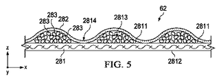
一実施形態では、吸収性物品は実質的にセルロースを含まない吸収性コア62を含む。好適な吸収性コア62の例の断面図が、図5〜図7に模式的に示されている。吸収性コア62は、その主な役割が液体の身体排出物を吸収して、保持する吸収性物品の要素である。吸収性物品のトップシート58と、吸収性コア62の間に追加の要素を追加して、身体排出物の捕捉及び分配を促進してもよい。かかる要素は例えば、当該技術分野において周知であるような捕捉層及び/又は分配層を含み得る。捕捉層及び/又は分配層自体は、実質的にセルロースを含んでいなくてもよいし(例えば、全体が不織布材料から作製される)、又は多量のセルロース材料を含んでいてもよい。吸収性コア62は一般的に、例えば吸収性ポリマーなど、高い保持能力を有する粒子状の吸収性材料を含み、これらの材料は、吸収性コア62の全長に沿って存在する必要はない。股部領域30及び/又は前側領域26においては、後側領域28と比較して、より多くの量の吸収性材料が含まれ、後側領域28では、存在する場合であっても、わずかしか吸収性材料が含まれないような、吸収性コア62を提供することが有利となる場合もある。一実施形態では、吸収性コア62は、材料の第1の層281及び第2の層282、並びに第1の層281と第2の層282との間に配置された吸収性材料283を含む。一実施形態においては、材料の第1の層281及び第2の層282は、不織布繊維ウェブ、織布繊維ウェブ、及び熱可塑性接着材料の層のうちの少なくとも1つから選択される繊維材料であり得る。第1の層281及び第2の層282は、同一の材料から作製されてもよいが、一実施形態においては、第1の層281は不織布繊維ウェブであり、第2の層282は、熱可塑性接着材料の層である。不織布繊維ウェブ281は、例えばPE、PET、及びPPの単成分繊維、また例えばサイドバイサイド、コア/シース、又はアイランドインザシータイプの多成分繊維などの合成繊維を含み得る。そのような合成繊維は、スパンボンドプロセス又はメルトブロープロセスを介して形成されてもよい。不織布繊維ウェブ281には、繊維の単一層が含まれ得るが、多層の繊維、例えば多層のスパンボンド繊維、多層のメルトブロー繊維、又はスパンボンドとメルトブロー繊維の個々の層の組み合わせによる不織布ウェブを提供することが有利な場合もある。一実施形態においては、不織布ウェブ281は、ウェブの繊維の表面エネルギーを増加させる薬剤(例えば、界面活性剤)で処理されてもよい。このような薬剤は、尿などの液体に対して、不織布ウェブの透過性を高めるものである。他の実施形態においては、不織布ウェブは、不織布ウェブの繊維の表面エネルギーを低下させる薬剤(例えば、シリコーン)で処理されてもよい。このような薬剤は、尿などの液体に対して、不織布ウェブの透過性を低下させるものである。
In one embodiment, the absorbent article includes an
第1の層281は、第1の表面2811と第2の表面2812とを含み、少なくとも第1の表面2811の領域2813は、かなりの量の吸収性材料283と直接面する関係にある。一実施形態においては、吸収性材料は、かなりの量の吸収性高分子材料283に直接面する関係にある第1の層281上の領域2813と、ほんのわずかな量の吸収性材料とのみ面する関係にある第1のウェブ上の領域2814とが形成されるパターンで、第1の表面2811上に堆積される。「かなりの量の吸収性材料に直接面する関係」とは、一部の吸収性材料が、少なくとも100g/m2、少なくとも250g/m2、又は少なくとも500g/m2の坪量で領域2813の上に堆積されるという意味である。このパターンは、全てが同じ形状及び寸法(即ち、投影した表面積及び/又は高さ)を有する領域を有してもよい。代替的なパターンでは、領域間で勾配が形成されるように、異なる形状又は寸法を有する領域が含まれてもよい。領域2813の少なくとも一部は、1cm2〜150cm2、又は更には5cm2〜100cm2の突出表面積を有し得る。「わずかな量の吸収性材料に面する関係」とは、一部の吸収性材料が、100g/m2未満、50g/m2未満の坪量で領域2814の表面上に堆積されてもよく、又は実質的に吸収性材料がなくてもよいということを意味する。領域2814の少なくとも一部は、1cm2〜150cm2、又は更には5cm2〜100cm2の突出表面積を有することができる。全ての領域2813の凝集した突出表面積は、第1の層281の第1の表面2811の突出表面積合計の10%〜90%、又は更には25%〜75%を表してもよい。一実施形態においては、第2の層282は、熱可塑性接着材料の層である。「熱可塑性接着材料」は、本明細書で使用する場合、繊維の形成材料であるポリマー組成物であって、乾燥した状態及び濡れた状態の両方において吸収性材料を固定化する目的で吸収性材料に適用されるポリマー組成物を意味すると理解される。熱可塑性接着材料の非限定的な例は、単一の熱可塑性ポリマー又は熱可塑性ポリマーのブレンドを含み得る。熱可塑性接着材料はまた、少なくとも1つの熱可塑性ポリマーを、粘着付与樹脂、可塑剤、及び酸化防止剤などの添加剤のような他の熱可塑性希釈剤と組み合わせて含むホットメルト接着剤であってもよい。ある特定の実施形態において、熱可塑性ポリマーは典型的に、10,000超の分子量(Mw)、及び一般的に室温未満、又は−6℃<Tg<16℃のガラス転移温度(Tg)を有する。ある特定の実施形態において、ホットメルト内におけるポリマーの典型的な濃度は、約20重量%〜約40重量%の範囲内にある。例示的なポリマーは、A−B−A三元ブロック構造、A−B二元ブロック構造、及び(A−B)n放射状ブロックコポリマー構造を含む(スチレン)ブロックコポリマーであり、Aブロックは、典型的にはポリスチレンを含む非エラストマーポリマーブロックであり、Bブロックは、不飽和共役ジエン又はその(部分的に)水素添加物である。Bブロックは典型的には、イソプレン、ブタジエン、エチレン/ブチレン(水素添加ブタジエン)、エチレン/プロピレン(水素添加イソプレン)、及びこれらの混合物である。使用可能な他の好適な熱可塑性ポリマーは、単一サイト触媒又はメタロセン触媒を用いて調製されるポリマーである、メタロセンポリオレフィンである。実施形態のいくつかの例においては、粘着付与樹脂は、典型的には5,000未満の分子量(Mw)と、通常、室温よりも高いTgとを有し、ホットメルト中の樹脂の典型的な濃度は、約30重量%〜約60重量%の範囲内であり、可塑剤は典型的には1,000未満の低い分子量(Mw)と、室温よりも低いTgを有し、典型的な濃度は約0%〜約15%である。
The
熱可塑性接着材料282は、吸収性材料283内に実質的に均一に配置されてもよい。代替的には、熱可塑性接着材料282は、吸収性材料283の表面上、及びわずかな量の吸収性材料とのみ面する関係にある第1の表面2811の領域2814上に配置される繊維層として提供可能である。一実施形態においては、熱可塑性接着材料は、1g/m2〜20g/m2、1g/m2〜15g/m2、又は2g/m2〜8g/m2の量で適用される。第1の層281上の吸収性材料の不連続な堆積により、熱可塑性材料282の繊維層に、本質的に三次元的な構造体が付与される。換言すれば、熱可塑性接着材料の層は、第1の不織布繊維ウェブ281上に堆積された吸収性材料283と、わずかな量の吸収性材料のみを含む領域2814とから生じるトポグラフィに従う。理論に縛られずに言えば、本明細書に開示される熱可塑性接着材料は、乾燥及び湿潤状態における吸収性材料の固定化を強化すると考えられる。
The thermoplastic
一実施形態においては、吸収性コア62は、不織布繊維材料284の第2の層を更に含み得る。この第2の層284は、不織布繊維層281と同一の材料から提供されてもよいし、代替的には、異なる材料から提供されてもよい。第1の不織布繊維層281と第2の不織布繊維層284を異ならせて、これらの層が異なる機能性を提供するようにすることは有利であり得る。一実施形態では、第1の不織布層281の表面エネルギーは、第2の不織布層284の表面のエネルギーと異なっていてもよい。一実施形態では、第2の不織布層284の表面エネルギーは、第1の不織布層281の表面エネルギーよりも大きい。利点の中でも、第2の不織布層284の表面エネルギーが、第1の不織布層281の表面エネルギーよりも大きい場合には、尿などの液体が、第2の不織布層284をより容易に透過し、吸収性材料に到達して保持されることが可能となる一方で、液体が第1の層281を透過して、通り抜けてしまう可能性を低減させることができると考えられる。このことは、第1の不織布層281が、吸収性物品のバックシートに接して配置される場合に、特に有利であり得る。各層に異なる表面エネルギーを与えるために、例えば、第1の不織布層281に適用される界面活性剤(使用する場合)の量とは異なる量の薬剤(界面活性剤など)を第2の不織布層284へ適用することもできる。このことは、第2の不織布層284に、第1の不織布層281に適用される界面活性剤とは異なるタイプの界面活性剤を適用することによっても達成され得る。これはまた更に、第1の不織布層281に表面エネルギーを低下させる材料を適用することによっても達成され得る。異なる表面エネルギーを有することに加えて、又は代替的に、第1の不織布繊維層281と第2の不織布繊維層284とは、構造的にも異なっていてよい。一実施形態では、第1の不織布層281は、第2の不織布層284とは異なる繊維の層を含んでいてよい。例えば、第2の不織布層284はスパンボンド繊維の1つ又は2つ以上の層のみを含んでもよいのに対して、第1の不織布層281はスパンボンド繊維の1つ又は2つ以上の層と、メルトブローン繊維の1つ又は2つ以上の層と、を含む。他の実施形態においては、不織布繊維層281、284の両方が、スパンボンド繊維の1つ又は2つ以上の層と、メルトブローン繊維の1つ又は2つ以上の層と、を含んでもよいが、これら第1の層281及び第2の層284は、不織布材料を形成するために使用される繊維の化学組成、繊維のデニール、及び/又は不織布材料の坪量のうちの少なくとも1つに関して異なっている。これに加えて、又は上記したものに代えて、第1の不織布層281及び第2の不織布層284は、それらの対応する水頭値、それらの対応する多孔性、それらの対応するフラジール浸透性、及びそれらの対応する引張特性のうちの少なくとも1つに関して異なってもよい。第2の不織布層284は、第1の不織布層281、吸収性材料283、及び熱可塑性接着材料282の上面に直接適用されてもよい。結果として、第1の不織布層281及び第2の不織布層284は、吸収性材料283を更に包囲して固定化する。
In one embodiment, the
領域2813は、吸収性コア62のx−y次元においては、任意の適当な形状であってよい。一実施形態においては、領域2813は、第1のウェブ281の第1の表面2811上に広がる円板のパターンを形成する。一実施形態においては、領域2813は、吸収性コア62の長手方向軸線に沿って(即ち、y次元に沿って)連続的に延在する、長手方向の「ストリップ」のパターンを形成する。代替的な1つの実施形態においては、これらのストリップは、吸収性物品の長手方向軸線に対して、10°〜90°、20°〜80°、30°〜60°、又は45°の角度を形成するように配列されてもよい。
一実施形態においては、既に述べたように、第2の不織布層284は第1の表面2841と、第2の表面2842と、第1の表面2841に適用される吸収性材料283とを有し、かなりの量の吸収性材料283と直接面する関係にある領域2843と、第1の表面2841上にあり、わずかな量の吸収性材料のみと面する関係にある領域2844と、からなるパターンを形成する。一実施形態においては、第1のウェブ/吸収性材料/熱可塑性接着材料複合体との関連で既に述べたように、熱可塑性接着材料285が、第2の不織布層284の上に更に適用されてもよい。次いで、第2の不織布層284を、第1の不織布層281の上面に適用してもよい。一実施形態においては、第2の不織布層284上に存在する吸収性材料のパターンは、第1の不織布層281上に存在する吸収性材料のパターンと同一であってもよい。他の実施形態では、第1の不織布層281及び第2の不織布層284上に存在する吸収性材料のパターンは、領域の形状、領域の突出表面積、領域上に存在する吸収性材料の量、及び領域上に存在する吸収性材料の種類のうちの少なくとも1つにおいて異なる。第1の不織布層281及び第2の不織布層284上に存在する吸収性材料のパターンが異なる場合、各層/吸収性複合物に、例えば、異なる吸収能力及び/又は液体の異なる捕捉速度など、異なる機能を持たせ得ると考えられる。例えば、吸収性材料の領域2843(即ち、第2の不織布層284上の領域)によって形成される第2のパターンが、吸収性材料の領域2813の第1のパターンよりも遅い吸収速度を呈する構造を備える吸収性コア62を提供し、液体(例えば尿)が、領域2843における吸収性材料が膨張する前に、第1の不織布層281上に堆積された吸収性材料に到達し、これによって吸収され得るようにすることが有益な場合もある。かかる構造体により、領域2843に存在する吸収性材料による有意なゲルブロッキングが回避される。また、かなりの量の吸収性材料に直接面する関係にある第1の不織布層281の領域2813の少なくとも一部、又は全てが、わずかな量の吸収性材料に面する関係にある第2のウェブ284の対応する領域2844とも、実質的に面する関係となるように、第2の層284/吸収性材料/熱可塑性接着材料複合体を適用することも有利であり得る。
In one embodiment, the second
吸収性コア62はまた、図面には示されていない補助接着剤を含んでもよい。吸収性材料の接着性、及び熱可塑性接着材料282、285の対応する不織布層281、284への接着性を向上させるために、吸収性材料283の適用前に、補助接着剤が、第1の不織布層281及び第2の不織布層284のうちの少なくとも一方、又は両方の上に堆積されてもよい。補助接着剤はまた、吸収性材料の固定化を補助することもでき、本明細書にて上記したものと同じ熱可塑性接着材料を含んでもよいし、限定するわけではないが、噴霧可能なホットメルト接着剤、例えばH.B.Fuller Co.(St.Paul、MN)製品番号HL−1620−Bなどの、他の接着剤も含んでもよい。補助接着剤は、任意の好適な手段によって不織布層281、284に適用されてよいが、特定の実施形態によると、約0.5〜約2mm離れた約0.5〜約1mm幅のスロットに適用されてよい。好適な吸収性材料283の非限定的な例としては、遠心分離保持容量試験(Edana 441.2−01)を用いて測定したときに、自身の重量の少なくとも5倍の0.9%食塩水溶液を吸収可能な架橋ポリマー材料などの、吸収性ポリマー材料が挙げられる。
The
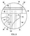
再び図1を参照すると、上述したように、一実施形態においては、吸収性物品20は、前側ベルト84と、後側ベルト86と、本体38と、を含むパンツ式おむつであり、前側ベルト84及び後側ベルト86は、内側シート94、外側シート92、及び内側シート94と外側シート92との間に挟まれ、横方向に延びる複数の弾性体96によって形成される。図1の領域IIの分解図である図8を参照すると、弾性ベルト40の弾性体96と外側カフ66の第1のカフ弾性要素72及び第2のカフ弾性要素74との間の関係が示されている。前側ベルト84又は後側ベルト86のいずれかの近位縁部90の近傍において、弾性ベルト40の弾性体96、及び外側カフ66の第1のカフ弾性要素72及び第2のカフ弾性要素74は、互いに対して非常に接近して配置され得、何枚かのシートによってのみ、例えば、内側シート94、外側カバー層42、及びバックシート60によってのみ分離され得る。ベルトの弾性体96の張力が第1のカフ弾性要素72及び第2のカフ弾性要素74の張力に伝達され得る場合、多くの不利益が生じ得る。1つを挙げると、これにより、脚部開口部の可撓性が損なわれる場合がある。また、これにより、この領域の柔軟性が妨げられる場合がある。更に、これにより、ほぼ垂直方向において、弾性体の交差点が生まれ、組み立て後の物品の移送の効率が低下し得る。
Referring back to FIG. 1, as described above, in one embodiment, the absorbent article 20 is a pants-type diaper that includes the
したがって、一実施形態においては、本発明の前側ベルト84、後側ベルト86、及び本体38は、第1のカフ弾性要素72及び第2のカフ弾性要素74のいずれの張力も、前側ベルト84又は後側ベルト86の弾性体96のいずれかに対して伝達されないように構成されていてよい。張力の伝達を防ぐため、一実施形態においては、第1のカフ弾性要素72及び第2のカフ弾性要素74が物品の厚さ方向において重なり合う領域においては、本体38が、前側ベルト84及び後側ベルト86に取り付けられていないか、又は接合されていなくてもよい。他の実施形態においては、張力の伝達を防ぐため、ベルト弾性体96は、図8のように、長手方向において、第1のカフ弾性要素72及び第2のカフ弾性要素74の外側に位置していてもよい。
Accordingly, in one embodiment, the
本発明の吸収性物品は、本体208の連続ウェブを形成する工程と、前側ベルト184又は後側ベルト186などの物品の他の要素の連続ウェブを形成する工程と、このような要素を組み立てる工程と、を含むが、これらに限定されない、テープ式吸収性物品、又はパンツ式吸収性物品を作製するための周知のプロセスにより作製されてよい。図1のようなパンツ式吸収性物品を高速で形成するために、本体208の連続ウェブを、物品の長手方向にウェブを前進させることによって、好適に作製することができる一方で、前側ベルト184又は後側ベルト186の連続ウェブを、物品の横方向にウェブを前進させることによって、好適に作製することができる。それ故、物品の組み立てプロセスの際には、要素を移送することが必要となり得る。
The absorbent article of the present invention includes forming a continuous web of
図9に示すように、本発明の物品を組み立てるために、本体38を作製するための連続ウェブ208を、ロール又は他の運搬機構上にて、第1の可動搬送部材204に向かって給送することにより前進させてよい。連続ウェブ208が前進させられる方向を、機械方向と考える。一度、本体38を形成するのに十分な長さのウェブ208の一部分が、第1の可動搬送部材204と係合し、かつ/又は移送アセンブリ200の移送部材212の一部分と係合すると、第1の可動搬送部材204と一体化したナイフが、アンビルロール214に当たって、ウェブ208を個別の本体38に切断することができる。ナイフは、可撓性のナイフ、ダイカッター、剪断ナイフ若しくは任意の他の好適なナイフ、又は切断デバイス若しくは機構であってよい。ナイフ及びアンビルロール214の技術は、当該技術分野において一般に既知である。他の実施形態においては、予め切り出した本体38を、第1の可動搬送部材204に向かうコンベヤ上に給送し得る。
As shown in FIG. 9, a
それぞれの移送部材212は、回転軸から最遠位の移送部材212の端部上に移送面236を備えてよい。移送面236は、個別の本体38のうちの1つ又は2つ以上をピックアップするように構成されていてよい。また、第1の可動搬送部材204と第2の可動搬送部材206との間で本体38を移送するとき、移送部材212の各部分は、第1の位置216と少なくとも第2の位置218との間で方向転換させられてもよい。結果として、本体38は、第1の位置216と第2の位置218との間で方向転換させられ得る。移送部材212の各部分は、それぞれの移送部材212の一部分と係合した回転アセンブリを使用して方向転換させられてもよい。本体38は、特定の角度、又は約90度の間で方向転換させられ得る。任意選択的には、本体38は、全く方向転換させられなくてもよく、移送アセンブリ200が、本体38を方向転換させずに、本体38を搬送及び/又はリピッチするために使用されてもよい。
Each
本体38のピックアップ、方向転換、回転、及びリピッチのうちの1つ又は2つ以上の様々な実施形態において、移送部材212の移送面236は、真空引きによって本体38を移送面236上に保持するように構成されてよい。この移送プロセス全体の間、本体38は、本体38の各要素が意図した設計からずれてしまわないように、移送面236によってしっかりと保持される必要がある。特に重要なのは、長手方向の周縁に沿って存在し、弾性のある外側カフ66について、意図した設計が維持されることである。上述したように構成した外側カフ66が提供されることにより、より張力が強い第1のカフ弾性要素72は、たとえ残りの、より張力が弱い第2のカフ弾性要素74がバックシート60に接着されていない場合であっても、バックシート60に補助されて、移送面236に対してしっかりと保持され得る。したがって、図9に示した移送プロセスの際、本発明の外側カフ66により、本体38の製造公差が確保される。
In various embodiments of one or more of pickup, redirection, rotation, and re-pitch of the
図9を再び参照すると、前側ベルト84及び後側ベルト86を作製するための連続ウェブ184、186が、ローラ、コンベヤ、又は他の機構上で、第2の可動搬送部材206に向かい、第2の可動搬送部材206の上に乗り、そして第2の可動搬送部材206から離れるように、平行に移動していてもよい。これらのウェブ184、186は、一例においては、連続的なものであってよいが、他の実施形態においては、連続ウェブから予め切り出した個別の構成材であってもよい。接着剤ディスペンサー228を使用して、構成材のウェブ又は個別の構成材に接着剤を適用してもよい。前側ベルト184又は後側ベルト186のウェブの各部分が第2の可動搬送部材206の上を移動させられる前に、接着剤ディスペンサー228により、これらの部分に接着剤を適用してもよい。結果として、第2の可動搬送部材206へ移送されている本体38は、第2の可動搬送部材206上へと移送されたときに、構成材のウェブ220に接着剤で取り付けられ得る。本体38の前側ウエストパネル52は、前側ベルト184の連続ウェブに接着剤で取り付けられ得、また本体38の後側ウエストパネル54は、後側ベルト186の連続ウェブに接着剤で取り付けられ得る。これにより、吸収性物品10のウェブが形成され得る。その後、吸収性物品10のウェブは、横方向の中心線T1に沿って折り畳まれ、縫い合わされ、個別のパンツ式吸収性物品へと分離され得る。
Referring again to FIG. 9, the
不透明度の方法
不透明度は、コンピュータインタフェースを備える、0°照明/45°検出、環状の光学的形状の分光光度計、例えばHunterLab LabScan XE running Universal Software(Hunter Associates Laboratory Inc.(Reston、VA)から入手可能)又は同等の機器を使用して測定される。機器校正及び測定は、販売元によって提供されている標準白黒校正プレートを使用して行う。全ての試験は、23℃±2℃及び相対湿度50%±2%で維持された室内で行う。
Opacity Methods Opacity is measured using a 0 ° illumination / 45 ° detection, circular optical shape spectrophotometer with a computer interface, such as HunterLab LabScan XE running Universal Software Inc. (from Hunter Associates Laboratory Inc., Reston, Inc., Reston). Available) or equivalent equipment. Instrument calibration and measurements are performed using standard black and white calibration plates provided by the vendor. All tests are performed in a room maintained at 23 ° C. ± 2 ° C. and 50% ± 2% relative humidity.
標準に設定されたUVフィルタと共に、分光光度計は、XYZカラースケール、D65光源、10°標準観測者に対して構成される。この機器を、製造元の手順に従い1.8cm(0.7インチ)ポート寸法及び1.3cm(0.5インチ)視野域を使用して標準化する。校正後、ソフトウェアはY不透明度手順に設定され、これは測定中に白又黒のいずれかの校正タイルで試料を覆うようにオペレータを促す。 Along with the UV filter set as standard, the spectrophotometer is configured for XYZ color scale, D65 light source, 10 ° standard observer. The instrument is standardized using a 1.8 cm (0.7 inch) port size and a 1.3 cm (0.5 inch) field of view according to the manufacturer's procedure. After calibration, the software is set to a Y opacity procedure, which prompts the operator to cover the sample with either a white or black calibration tile during the measurement.
約23℃±2℃及び約50%±2%の相対湿度で、試験前に約2時間にわたって、物品を事前調整する。試験片を得るため、物品を作業台上で身体に面する表面を上にして平らに引き伸ばし、物品の長手方向の全長を測定する。内側カフ64及び外側カフ66における試験部位は、物品の長手方向の中間点で選択する。左のカフの長手方向の中間点を中心とした、60mm長×内側カフ64の全高の大きさの試験片を、鋏で切断する。次に、今度は外側カフ66から、左の外側カフ66の長手方向の中間点を中心とした、60mm長×外側カフ66の全高の大きさの第2の試験片を切断する。同様に、内側カフ64及び外側カフ66の試験片を、物品の右側のカフから調製する。
The article is preconditioned at about 23 ° C. ± 2 ° C. and about 50% ± 2% relative humidity for about 2 hours prior to testing. To obtain a test piece, the article is stretched flat on the work surface with the body-facing surface up, and the total length of the article is measured. The test sites in the
試験片を測定ポートに被せて置く。試験片は、カフの内側を向いた表面に対応する表面がポートの方を向いた状態で、ポートを完全に覆っている必要がある。試験片がその長手方向にピンと張った状態となるまで、緩やかに延伸させて、カフが、ポートのプレートに対して平らに置かれるようにする。接着テープを貼って、カフが試験のための延伸状態でポートプレートに対して固定されるようにする。テープは測定ポートのいずれの部分も覆ってはならない。次いで、試験片を、白い標準プレートで覆う。表示を読み取り、次いで白いタイルを取り除き、試験片を動かさないで、黒い標準タイルと交換する。2回目の表示を読み取り、不透明度を以下のように計算する:
不透明度=(Y値(黒色裏材)/Y値(白色裏材))×100
Place the specimen over the measurement port. The test piece must completely cover the port with the surface corresponding to the surface facing the inside of the cuff facing the port. Gently stretch until the specimen is taut in its longitudinal direction so that the cuff lies flat against the port plate. Adhesive tape is applied so that the cuff is secured to the port plate in the stretched state for testing. The tape must not cover any part of the measuring port. The specimen is then covered with a white standard plate. Read the display, then remove the white tile and replace it with a black standard tile without moving the specimen. Read the second display and calculate the opacity as follows:
Opacity = (Y value (black backing) / Y value (white backing) ) × 100
5つの同じ物品からの試験片(10の内側カフ(左側から5つ、右側から5つ)並びに10の外側カフ(左側から5つ、右側から5つ))を分析し、それらの不透明度を記録する。これらの内側カフ64及び外側カフ66の平均不透明度を計算し、それぞれ0.01%単位で記録する。
Specimens from 5 identical articles (10 inner cuffs (5 from the left, 5 from the right) as well as 10 outer cuffs (5 from the left, 5 from the right)) were analyzed and their opacity was analyzed. Record. The average opacity of these
空気透過率試験
特注の1cm2の円形アパーチャ(Advanced Testing Instrumentsから入手可能)を備える、TexTest FX3300 Air Permeability Tester(Advanced Testing Instruments(Greer、SC)から入手可能)又は同等の機器を使用して空気透過率の試験を行う。製造元の手順に従って機器を標準化する。全ての試験は、23℃±2℃及び相対湿度50%±2%で維持された室内で行う。
Air Permeability Test A TextTest FX3300 Air Permeability Tester (available from Advanced Testing Instruments (Greer, SC) equipment, available from Advanced Testing Instruments) equipped with a custom-made 1 cm 2 circular aperture (available from Advanced Testing Instruments). Perform rate testing. Standardize equipment according to manufacturer's procedures. All tests are performed in a room maintained at 23 ° C. ± 2 ° C. and 50% ± 2% relative humidity.
約23℃±2℃及び約50%±2%の相対湿度で、試験前に約2時間にわたって、物品を事前調整する。試験片を得るため、物品を作業台上で身体に面する表面を上にして平らに引き伸ばし、物品の長手方向の全長を測定する。内側カフ64及び外側カフ66における試験部位は、物品の長手方向の中間点で選択する。左のカフの長手方向の中間点を中心とした、30mm長×内側カフ64の全高の大きさの試験片を、鋏で切断する。次に、今度は外側カフから、左の外側カフ66の長手方向の中間点を中心とした、30mm長×外側カフ66の全高の大きさの第2の試験片を切断する。同様に、内側カフ64及び外側カフ66の試験片を、物品の右側のカフから調製する。弾性部材は全て取り除く。
The article is preconditioned at about 23 ° C. ± 2 ° C. and about 50% ± 2% relative humidity for about 2 hours prior to testing. To obtain a test piece, the article is stretched flat on the work surface with the body-facing surface up, and the total length of the article is measured. The test sites in the
測定ポートに被さるように試験片を中心に置く。試験片は、カフの内側を向いた表面に対応する表面がポートの方を向いた状態で、ポートを完全に覆っている必要がある。試験片がピンと張った状態となるまで、その長手方向に緩やかに延伸させて、カフが、ポートをまたいで平らに置かれるようにする。接着テープを貼って、カフが試験のための延伸状態で、ポートをまたいで固定されるようにする。テープは測定ポートのいずれの部分も覆ってはならない。空気が試験片を通過できるように、試験圧力を設定する。不織布カフの場合、圧力は125Paに設定し、フィルムを含むカフの場合は、2125Paを使用する。試料リングを閉じて、測定値が機器の許容限度内にあるということを示す緑色を、範囲表示器が示すまで、測定範囲を調整する。空気透過率は0.1m3/m2/分単位で記録する。 Center the specimen over the measurement port. The test piece must completely cover the port with the surface corresponding to the surface facing the inside of the cuff facing the port. Gently stretch in the longitudinal direction until the specimen is taut so that the cuff lies flat across the port. Adhesive tape is applied so that the cuff is secured across the port in the stretched state for testing. The tape must not cover any part of the measuring port. Set the test pressure so that air can pass through the specimen. In the case of a non-woven cuff, the pressure is set to 125 Pa, and in the case of a cuff including a film, 2125 Pa is used. Close the sample ring and adjust the measurement range until the range indicator shows a green color indicating that the measurement is within the acceptable limits of the instrument. Air permeability is recorded in units of 0.1 m 3 / m 2 / min.
静水頭の試験
TexTest FX3000 Hydrostatic Head Tester(Advanced Testing Instruments(Greer、SC)から入手可能)に、カスタムメイドの1.5cm2の円形測定ポート(同様に、Advanced Testing Instrumentsから入手可能)を備え付けたものを使用して静水頭の試験を行う。測定ポートの周囲のガスケットと同じ寸法の2つの環状スリーブリングを、微細不織布用の標準的な保護スリーブ(Advanced Testing Instrumentsから入手可能な部品、FX3000−NWH)から切り出す。続いて、クランプの際に試験片を保護するために、これらのスリーブリングを、前記TexTest製機器の、上側ガスケット及び下側ガスケットの試料対向面に、両面接着テープを用いて貼り付ける。製造元の手順に従って機器を標準化する。全ての試験は、約23℃±2℃及び相対湿度約50%±2%で維持された室内で行う。
Hydrostatic head test The TexTest FX3000 Hydrostatic Head Tester (available from Advanced Testing Instruments (Grea, SC)) with a custom-made 1.5 cm 2 circular measurement port (also available from Advanced Testing Instruments). To test the hydrostatic head. Two annular sleeve rings of the same dimensions as the gasket around the measurement port are cut from a standard protective sleeve for fine nonwovens (part available from Advanced Testing Instruments, FX3000-NWH). Subsequently, in order to protect the test piece during clamping, these sleeve rings are attached to the sample facing surfaces of the upper gasket and the lower gasket of the TexTest equipment using a double-sided adhesive tape. Standardize equipment according to manufacturer's procedures. All tests are performed in a room maintained at about 23 ° C. ± 2 ° C. and a relative humidity of about 50% ± 2%.
約23℃±2℃及び約50%±2%の相対湿度で、試験前に約2時間にわたって、物品を事前調整する。試験片を得るため、物品を作業台上で身体に面する表面を上にして平らに引き伸ばし、物品の長手方向の全長を測定する。内側カフ64及び外側カフ66における試験部位を、物品の長手方向の中間点で選択する。左のカフの長手方向の中間点を中心とした、70mm長×内側カフ64の全高の大きさの試験片を、鋏で切断する。次に、今度は外側カフから、左の外側カフの長手方向の中間点を中心とした、70mm長×外側カフ66の全高の大きさの第2の試験片を切断する。同様に、内側カフ64及び外側カフ66の試験片を、物品の右側のカフから調製する。弾性部材は全て取り除く。
The article is preconditioned at about 23 ° C. ± 2 ° C. and about 50% ± 2% relative humidity for about 2 hours prior to testing. To obtain a test piece, the article is stretched flat on the work surface with the body-facing surface up, and the total length of the article is measured. The test sites in the
上側のテストヘッドのポートに被さるように試験片を中心に置く。試験片は、カフの外側を向いた表面に対応する表面がポートの方を向いた状態で、ポートを完全に覆っている必要がある(即ち、内側を向いた表面は水に面することになる)。試験片がその長手方向にピンと張った状態となるまで、緩やかに延伸させて、カフが、上側の試験プレートに対して平らに置かれるようにする。接着テープを貼って、カフが試験のための延伸状態で試験プレートに対して固定されるようにする。テープは測定ポートのいずれの部分も覆ってはならない。 Center the test piece over the upper test head port. The specimen must completely cover the port with the surface corresponding to the outward facing surface of the cuff facing the port (i.e. the inward facing surface must face the water). Become). Gently stretch until the specimen is taut in its longitudinal direction so that the cuff lies flat against the upper test plate. Adhesive tape is applied so that the cuff is secured to the test plate in the stretched state for testing. The tape must not cover any part of the measuring port.
TexTestのシリンジに蒸留水を充填し、下側の試験プレートの測定ポートを通して蒸留水を加える。水位が下側ガスケットの頂部までくるように、充填を行う必要がある。上側のテストヘッドを機器の上に載置し、テストヘッドを下げて試験片の周囲を封止する。試験速度は、50hPa/分(50mbar)以下の静水頭を有する試料については3hPa/分(3mbar/分)、50hPa(50mbar)を超える静水頭を有する試料については60hPa/分(60mbar/分)に設定する。試験を開始し、試験片表面を観察して、表面を透過する水滴を検出する。試験片の表面に水滴が1つ検出されるか、又は圧力が200hPa(200mbar)を超える場合は、試験を終了する。この圧力を0.5hPa(0.5mbar)単位で記録し、透過が検出されなかった場合は、200hPa(200mbar)超として記録する。 Fill a TexTest syringe with distilled water and add distilled water through the measurement port of the lower test plate. Filling should be done so that the water level reaches the top of the lower gasket. The upper test head is placed on the instrument, and the test head is lowered to seal the periphery of the test piece. The test rate is 3 hPa / min (3 mbar / min) for samples with a hydrostatic head of 50 hPa / min (50 mbar) or less, and 60 hPa / min (60 mbar / min) for samples with a hydrostatic head above 50 hPa (50 mbar). Set. The test is started and the surface of the test piece is observed to detect water droplets passing through the surface. If one water drop is detected on the surface of the test piece or the pressure exceeds 200 hPa (200 mbar), the test is terminated. This pressure is recorded in units of 0.5 hPa (0.5 mbar), and if no transmission is detected, it is recorded as over 200 hPa (200 mbar).
合計5つの同じ物品(10個の内側カフ試験片、及び10個の外側カフ試験片)を分析し、それらの静水頭値を記録する。これらの内側カフ64及び外側カフ66に対する平均静水頭を計算及び記録し、それぞれ0.1hPa(0.1mbar)単位で記録する。
A total of 5 identical articles (10 inner cuff specimens and 10 outer cuff specimens) are analyzed and their hydrostatic head values are recorded. The average hydrostatic head for these
(実施例1)
では、Toray Polytech NantongからLIVSEN SMS 15の商品名で提供されているSMSタイプの不織布材料をカフ層100として用い、次に示す寸法を有する、図2のカフ構成を有するパンツ式吸収性物品。
Example 1
A pant-type absorbent article having the cuff configuration of FIG. 2 using an SMS-type non-woven material provided by Toray Polytech Nanton under the trade name LIVSEN SMS 15 as the

(実施例2)
内側カフが1層のみによって形成され(図10の内側カフと同様)、PGI Spainから商品名CoPHOB15 P11 Vとして提供されているSMNSタイプの不織布材料をカフ層100として用いたことを除き、実施例1のカフ構成を有するパンツ式吸収性物品。
(Example 2)
Example, except that the inner cuff is formed by only one layer (similar to the inner cuff of FIG. 10) and the SMNS type non-woven material provided by PGI Spain under the trade name CoPHOB15 P11 V is used as the cuff layer 100 A pants-type absorbent article having a cuff configuration of 1.
比較例1
図10の内側カフ64、外側カフ66構成を採用し、次に示す寸法を有することを除き、実施例1と同一の材料及び構造で作製したパンツ式吸収性物品。
Comparative Example 1
A pants-type absorbent article made of the same material and structure as in Example 1 except that the
比較例1と比較すると、実施例1及び2は、漏れ防止性能を維持したまま、触覚及び知覚される柔軟性、レッグカフの柔軟性、及び脚部へのフィット性のうちの1つ又は2つ以上において向上している。 Compared to Comparative Example 1, Examples 1 and 2 are one or two of tactile and perceived flexibility, leg cuff flexibility, and leg fit while maintaining leakage prevention performance. This is an improvement.
消費者の受け止め
同じ吸収性コアを含む実施例1及び比較例1について、それぞれ50人、51人のパネリストに対して適用する、消費者テストを行った。パネリストは、年齢0か月〜36か月までの、男女比はほぼ等しい日本サイズ4号(Lサイズ)の着用者の世話をしている人々であった。世話をしているパネリストの人々は、いずれかの製品を5日間使用するのに十分な量の製品を与えられ、その後、下記の質問を含む質問票に回答し、性能について、「非常に悪い」から「非常に良い」までの5段階で評価するように求められた。100は「非常に良い」、75は「良い」、50は「普通」、25は「悪い」、そして「0」は「非常に悪い」を示す。これらの評価の平均をとり、統計的に分析した。試験の結果を下の表3に示す。
Consumer acceptance Consumer tests were applied to Example 1 and Comparative Example 1 that included the same absorbent core, applied to 50 and 51 panelists, respectively. The panelists were people who were taking care of wearers of Japanese size 4 (L size) who were almost equal in gender ratio from age 0 months to 36 months. The panelists who are taking care of are given enough products to use either product for 5 days, and then answer a questionnaire containing the following questions about performance: “Very bad ”To“ Very good ”. 100 indicates “very good”, 75 indicates “good”, 50 indicates “normal”, 25 indicates “bad”, and “0” indicates “very bad”. These evaluations were averaged and statistically analyzed. The results of the test are shown in Table 3 below.
消費者の受け止め試験の結果によれば、本発明の実施例1は、比較例1と比べて、上に列挙した製品の全ての点でより好意的に受け止められており、「製品のすべての点をお考えになって」及び「足周りのギャザー部分のやわらかさ」の点で、統計的に有意により良く受け止められていた。 According to the results of consumer acceptance tests, Example 1 of the present invention is more favorably accepted in all respects of the products listed above than Comparative Example 1, It was accepted statistically significantly better in terms of “considering the point” and “softness of the gathered area around the foot”.
本明細書に開示した寸法及び値は、示された数値そのものに厳密に限定されるものとして理解すべきではない。それよりむしろ、特に指示がない限り、このような寸法はそれぞれ、示された値とその値を囲む機能的に同等な範囲との両方を意味することを意図する。例えば、「40mm」として開示されている寸法は、「約40mm」を意味することを意図している。 The dimensions and values disclosed herein are not to be understood as being strictly limited to the numerical values shown. Instead, unless otherwise indicated, each such dimension is intended to mean both the recited value and a functionally equivalent range surrounding that value. For example, a dimension disclosed as “40 mm” is intended to mean “about 40 mm”.
「発明を実施するための形態」の中で引用された全ての文献は、関連部分において本明細書に参照により援用されている。いかなる文書の引用も、それが本発明に対する先行技術であることを認めるものとして解釈されるべきではない。本明細書における用語のいずれかの意味又は定義が、参照により組み込まれる文献における用語のいずれかの意味又は定義と矛盾する範囲においては、本明細書においてその用語に付与した意味又は定義を適用するものとする。 All references cited in “DETAILED DESCRIPTION” are hereby incorporated by reference in the relevant part. Citation of any document should not be construed as an admission that it is prior art to the present invention. To the extent that any meaning or definition of a term in this specification contradicts any meaning or definition of a term in a document incorporated by reference, the meaning or definition given to that term in this specification applies. Shall.
本発明の特定の実施形態を図示、及び説明したが、本発明の趣旨及び範囲から逸脱することなく、他の様々な変更及び改変を実施することが可能である点は当業者には自明であろう。したがって、本発明の範囲内に含まれるそのような全ての変更及び修正が、添付の特許請求の範囲内に網羅されることが意図される。 While particular embodiments of the present invention have been illustrated and described, it would be obvious to those skilled in the art that various other changes and modifications can be made without departing from the spirit and scope of the invention. I will. Accordingly, it is intended to embrace all such changes and modifications that fall within the scope of this invention within the scope of the appended claims.
Claims (26)
1)該長手方向及び該横方向に延在する透水性トップシートと、
2)該長手方向及び該横方向に延在し、かつ一対の長手方向側縁部を有する不透水性バックシートと、
3)該トップシートと該バックシートとの間に配置された吸収性コアであって、該バックシートは、該長手方向及び該横方向の両方において該吸収性コアを越えて延在する、吸収性コアと、
4)該バックシートの該衣類に面する側に配置された外側カバー層であって、該外側カバー層は、少なくとも該バックシートと同一の広がりを持つ、外側カバー層と、
5)脚部ガスケット機能を提供する一対の外側カフであって、それぞれの外側カフは、
a)長手方向に延在するように配置されたカフ封止部であって、該カフ封止部は、横方向において該吸収性コアと該バックシートの該長手方向側縁部との間に位置する、カフ封止部と、
b)長手方向に延在するように配置された少なくとも1つの弾性体を含む第1のカフ弾性要素であって、該第1のカフ弾性要素は、横方向において該バックシートの該長手方向側縁部の内側に位置しているが、横方向において該カフ封止部から3mmより内側には位置していない、第1のカフ弾性要素と、
c)長手方向に延在するように配置された少なくとも1つの弾性体を含む第2のカフ弾性要素であって、該第2のカフ弾性要素は、横方向において該バックシートの該長手方向側縁部の外側に位置し、該第2のカフ弾性要素のそれぞれの弾性体の張力は、該第1のカフ弾性要素のいずれの弾性体の張力に対しても70%以下となる、第2のカフ弾性要素と、
d)該第1のカフ弾性要素と該第2のカフ弾性要素との間に位置するカフギャップであって、該カフギャップは、少なくとも3mmの横方向幅を有する、カフギャップと、
e)長手方向に延在するように配置されたカフ外縁部であって、該カフ外縁部は、横方向において該第2のカフ弾性要素の外側に位置し、該カフ外縁部は、少なくとも5mmの横方向幅を有する、カフ外縁部と、を含む、一対の外側カフと、を含み、
該カフ封止部は、該カフ封止部が位置している所での、該物品の厚さ方向に存在する材料の全てを結合する、吸収性物品。 An absorbent article having a skin facing side, a garment facing side, a longitudinal axis, and a transverse axis, the absorbent article comprising:
1) a water permeable top sheet extending in the longitudinal direction and the transverse direction;
2) an impermeable backsheet extending in the longitudinal direction and the lateral direction and having a pair of longitudinal side edges;
3) an absorbent core disposed between the topsheet and the backsheet, the backsheet extending beyond the absorbent core in both the longitudinal direction and the transverse direction Sex core,
4) an outer cover layer disposed on the garment facing side of the backsheet, wherein the outer cover layer is at least coextensive with the backsheet;
5) A pair of outer cuffs providing leg gasket functions, each outer cuff being
a) a cuff sealing portion arranged so as to extend in the longitudinal direction, the cuff sealing portion between the absorbent core and the longitudinal side edge of the backsheet in the lateral direction A cuff sealing part located;
b) a first cuff elastic element comprising at least one elastic body arranged to extend in the longitudinal direction, the first cuff elastic element in the longitudinal direction of the backsheet in the longitudinal direction A first cuff elastic element located inside the edge but not laterally inward of the cuff seal from 3 mm;
c) a second cuff elastic element comprising at least one elastic body arranged to extend in the longitudinal direction, the second cuff elastic element in the longitudinal direction of the backsheet in the transverse direction The tension of each elastic body of the second cuff elastic element located outside the edge is 70% or less with respect to the tension of any elastic body of the first cuff elastic element. Cuff elastic element,
d) a cuff gap positioned between the first cuff elastic element and the second cuff elastic element, the cuff gap having a lateral width of at least 3 mm;
e) a cuff outer edge arranged to extend in a longitudinal direction, the cuff outer edge being laterally located outside the second cuff elastic element, the cuff outer edge being at least 5 mm A pair of outer cuffs including a cuff outer edge having a lateral width of
The absorbent article, wherein the cuff seal unit combines all of the material present in the thickness direction of the article where the cuff seal unit is located.
前記前側ベルト及び前記後側ベルトのそれぞれは、内側シート、外側シート、及び該内側シートと該外側シートとの間に挟まれ、かつ横方向に延びる複数の弾性体により形成されている、請求項20に記載の物品。 A center portion of the front belt is joined to a front waist panel of the main body, a center portion of the rear belt is joined to a rear waist panel of the main body, and the front belt and the rear belt are connected to the main body. A left side panel and a right side panel that do not overlap with each other, and a lateral edge of the front belt and a lateral edge of the rear belt are joined by a seam, and a waist opening and two leg openings Each front belt and rear belt has a laterally continuous proximal edge and a distal edge, the proximal edge being longer than the distal edge of the article. Close to the center of direction,
The front belt and the rear belt are each formed by an inner sheet, an outer sheet, and a plurality of elastic bodies that are sandwiched between the inner sheet and the outer sheet and extend in the lateral direction. 20. The article according to 20.
a)前記前側ベルトの連続ウェブ及び前記後側ベルトの連続ウェブを平行に前進させる工程と、
b)前記本体の連続ウェブを前進させる工程と、
c)前記本体の該連続ウェブを個別の本体に分離する工程と、
d)該個別の本体を移送面によってピックアップする工程であって、該本体は、真空引きによって該移送面上に保持される、工程と、
e)前記前側ベルトの該連続ウェブ、及び前記後側ベルトの該連続ウェブ上に該本体を移送する工程と、を含む、プロセス。 A process for manufacturing an article according to any one of claims 20 to 24, comprising:
a) advancing the continuous web of the front belt and the continuous web of the rear belt in parallel;
b) advancing the continuous web of the body;
c) separating the continuous web of the body into individual bodies;
d) picking up the individual body by a transfer surface, the body being held on the transfer surface by evacuation;
e) transferring the body onto the continuous web of the front belt and onto the continuous web of the rear belt.
Applications Claiming Priority (3)
| Application Number | Priority Date | Filing Date | Title |
|---|---|---|---|
| PCT/CN2014/085241 WO2016029369A1 (en) | 2014-08-27 | 2014-08-27 | Absorbent article with leg cuffs |
| CNPCT/CN2014/085241 | 2014-08-27 | ||
| PCT/CN2015/072195 WO2016029657A1 (en) | 2014-08-27 | 2015-02-04 | Absorbent article with leg cuffs |
Publications (2)
| Publication Number | Publication Date |
|---|---|
| JP2017523879A true JP2017523879A (en) | 2017-08-24 |
| JP2017523879A5 JP2017523879A5 (en) | 2018-10-18 |
Family
ID=55398584
Family Applications (1)
| Application Number | Title | Priority Date | Filing Date |
|---|---|---|---|
| JP2017508545A Ceased JP2017523879A (en) | 2014-08-27 | 2015-02-04 | Absorbent article with leg cuff |
Country Status (5)
| Country | Link |
|---|---|
| US (1) | US9980857B2 (en) |
| EP (1) | EP3185835B1 (en) |
| JP (1) | JP2017523879A (en) |
| CN (1) | CN106604708A (en) |
| WO (2) | WO2016029369A1 (en) |
Cited By (2)
| Publication number | Priority date | Publication date | Assignee | Title |
|---|---|---|---|---|
| JP2018134273A (en) * | 2017-02-22 | 2018-08-30 | 大王製紙株式会社 | Absorbent article |
| JP2020103430A (en) * | 2018-12-26 | 2020-07-09 | 花王株式会社 | Absorbent article |
Families Citing this family (7)
| Publication number | Priority date | Publication date | Assignee | Title |
|---|---|---|---|---|
| EP3233007B1 (en) | 2014-12-19 | 2020-11-18 | Essity Hygiene and Health Aktiebolag | Absorbent article |
| WO2016099363A1 (en) * | 2014-12-19 | 2016-06-23 | Sca Hygiene Products Ab | Absorbent article |
| KR101927040B1 (en) * | 2015-10-30 | 2018-12-07 | 킴벌리-클라크 월드와이드, 인크. | Absorbent article with channel and forming elastic member |
| CN105662728A (en) * | 2016-03-25 | 2016-06-15 | 湖南康程护理用品有限公司 | Absorption product with all-around leakproof structure and manufacturing method thereof |
| RU2769810C1 (en) * | 2018-07-31 | 2022-04-06 | Дайо Пейпер Корпорейшн | Disposable article for wearing |
| CN116940318A (en) * | 2021-03-04 | 2023-10-24 | 宝洁公司 | Absorbent article with leg gasketing system |
| WO2022183432A1 (en) * | 2021-03-04 | 2022-09-09 | The Procter & Gamble Company | Absorbent article with leg gasketing system |
Citations (4)
| Publication number | Priority date | Publication date | Assignee | Title |
|---|---|---|---|---|
| JP2012183134A (en) * | 2011-03-04 | 2012-09-27 | Oji Nepia Co Ltd | Disposable diaper |
| JP5184265B2 (en) * | 2008-08-29 | 2013-04-17 | 大王製紙株式会社 | Disposable diaper manufacturing method and disposable diaper |
| JP5369316B2 (en) * | 2009-10-20 | 2013-12-18 | 王子ホールディングス株式会社 | Absorbent articles |
| JP5479865B2 (en) * | 2009-11-30 | 2014-04-23 | 花王株式会社 | Pants-type absorbent article |
Family Cites Families (44)
| Publication number | Priority date | Publication date | Assignee | Title |
|---|---|---|---|---|
| US3860003B2 (en) | 1973-11-21 | 1990-06-19 | Contractable side portions for disposable diaper | |
| US4610678A (en) | 1983-06-24 | 1986-09-09 | Weisman Paul T | High-density absorbent structures |
| PH23956A (en) | 1985-05-15 | 1990-01-23 | Procter & Gamble | Absorbent articles with dual layered cores |
| IL82511A (en) | 1986-05-28 | 1992-09-06 | Procter & Gamble | Apparatus for and methods of airlaying fibrous webs having discrete particles therein |
| US4834735A (en) | 1986-07-18 | 1989-05-30 | The Proctor & Gamble Company | High density absorbent members having lower density and lower basis weight acquisition zones |
| US4892536A (en) | 1988-09-02 | 1990-01-09 | The Procter & Gamble Company | Absorbent article having elastic strands |
| US4990147A (en) | 1988-09-02 | 1991-02-05 | The Procter & Gamble Company | Absorbent article with elastic liner for waste material isolation |
| US5037416A (en) | 1989-03-09 | 1991-08-06 | The Procter & Gamble Company | Disposable absorbent article having elastically extensible topsheet |
| US5137537A (en) | 1989-11-07 | 1992-08-11 | The Procter & Gamble Cellulose Company | Absorbent structure containing individualized, polycarboxylic acid crosslinked wood pulp cellulose fibers |
| SE465121B (en) | 1990-06-19 | 1991-07-29 | Ante Eklund | AIR FILTERING DEVICE FOR CAR VEHICLES |
| US5151092A (en) | 1991-06-13 | 1992-09-29 | The Procter & Gamble Company | Absorbent article with dynamic elastic waist feature having a predisposed resilient flexural hinge |
| US5147345A (en) | 1991-08-12 | 1992-09-15 | The Procter & Gamble Company | High efficiency absorbent articles for incontinence management |
| US5260345A (en) | 1991-08-12 | 1993-11-09 | The Procter & Gamble Company | Absorbent foam materials for aqueous body fluids and absorbent articles containing such materials |
| US5387207A (en) | 1991-08-12 | 1995-02-07 | The Procter & Gamble Company | Thin-unit-wet absorbent foam materials for aqueous body fluids and process for making same |
| US5269775A (en) | 1992-06-12 | 1993-12-14 | The Procter & Gamble Company | Trisection topsheets for disposable absorbent articles and disposable absorbent articles having such trisection topsheets |
| US5397316A (en) | 1993-06-25 | 1995-03-14 | The Procter & Gamble Company | Slitted absorbent members for aqueous body fluids formed of expandable absorbent materials |
| JPH07142627A (en) | 1993-11-18 | 1995-06-02 | Fujitsu Ltd | Semiconductor device and manufacture thereof |
| AU1100395A (en) | 1993-11-19 | 1995-06-06 | Procter & Gamble Company, The | Absorbent article with multi-directional extensible side panels |
| US5643588A (en) | 1994-11-28 | 1997-07-01 | The Procter & Gamble Company | Diaper having a lotioned topsheet |
| US5554145A (en) | 1994-02-28 | 1996-09-10 | The Procter & Gamble Company | Absorbent article with multiple zone structural elastic-like film web extensible waist feature |
| US5635191A (en) | 1994-11-28 | 1997-06-03 | The Procter & Gamble Company | Diaper having a lotioned topsheet containing a polysiloxane emollient |
| US5580411A (en) | 1995-02-10 | 1996-12-03 | The Procter & Gamble Company | Zero scrap method for manufacturing side panels for absorbent articles |
| US5569234A (en) | 1995-04-03 | 1996-10-29 | The Procter & Gamble Company | Disposable pull-on pant |
| US5609587A (en) | 1995-08-03 | 1997-03-11 | The Procter & Gamble Company | Diaper having a lotioned topsheet comprising a liquid polyol polyester emollient and an immobilizing agent |
| US5607760A (en) | 1995-08-03 | 1997-03-04 | The Procter & Gamble Company | Disposable absorbent article having a lotioned topsheet containing an emollient and a polyol polyester immobilizing agent |
| US5571096A (en) | 1995-09-19 | 1996-11-05 | The Procter & Gamble Company | Absorbent article having breathable side panels |
| CA2166008A1 (en) * | 1995-12-18 | 1997-06-19 | Daniel Richard Laux | Absorbent article with improved elastic margins and containment system |
| US5865823A (en) | 1996-11-06 | 1999-02-02 | The Procter & Gamble Company | Absorbent article having a breathable, fluid impervious backsheet |
| US6107537A (en) | 1997-09-10 | 2000-08-22 | The Procter & Gamble Company | Disposable absorbent articles providing a skin condition benefit |
| DE60020536T2 (en) * | 1999-03-10 | 2005-10-27 | Kao Corporation | ABSORBENT ARTICLE |
| JP3626647B2 (en) * | 1999-11-30 | 2005-03-09 | ユニ・チャーム株式会社 | Disposable diapers |
| CN2421971Y (en) * | 2000-04-12 | 2001-03-07 | 富堡工业股份有限公司 | Leakage-proof paper urine-absorbing briefs |
| US20040002690A1 (en) * | 2002-07-01 | 2004-01-01 | The Procter & Gamble Company | Disposable absorbent article having elasticized outer leg cuff |
| WO2005077429A1 (en) | 2004-02-11 | 2005-08-25 | The Procter & Gamble Company | Hydrophobic surface coated absorbent articles |
| US20050215155A1 (en) | 2004-03-23 | 2005-09-29 | The Procter & Gamble Company | Absorbent article with improved opacity |
| US20050234411A1 (en) | 2004-04-14 | 2005-10-20 | The Procter & Gamble Company | Dual cuff for a unitary disposable absorbent article made of a continuous cuff material |
| JP5483682B2 (en) * | 2009-08-31 | 2014-05-07 | ユニ・チャーム株式会社 | Wearing article |
| JP5385075B2 (en) * | 2009-09-30 | 2014-01-08 | ユニ・チャーム株式会社 | Wearing article |
| BR112012020059A2 (en) * | 2010-02-10 | 2016-05-10 | Procter & Gamble | blanket material (s) for absorbent articles. |
| CA2834674C (en) * | 2011-04-29 | 2016-06-21 | The Procter & Gamble Company | Absorbent article with leg gasketing cuff |
| US20130211357A1 (en) * | 2012-02-13 | 2013-08-15 | The Procter & Gamble Company | Absorbent articles comprising substantially identical chassis |
| US8820513B2 (en) * | 2012-04-16 | 2014-09-02 | The Procter & Gamble Company | Methods for transferring discrete articles |
| US8979815B2 (en) * | 2012-12-10 | 2015-03-17 | The Procter & Gamble Company | Absorbent articles with channels |
| EP2740449B1 (en) * | 2012-12-10 | 2019-01-23 | The Procter & Gamble Company | Absorbent article with high absorbent material content |
-
2014
- 2014-08-27 WO PCT/CN2014/085241 patent/WO2016029369A1/en active Application Filing
-
2015
- 2015-02-04 JP JP2017508545A patent/JP2017523879A/en not_active Ceased
- 2015-02-04 EP EP15835810.1A patent/EP3185835B1/en active Active
- 2015-02-04 CN CN201580045487.8A patent/CN106604708A/en active Pending
- 2015-02-04 WO PCT/CN2015/072195 patent/WO2016029657A1/en active Application Filing
- 2015-08-27 US US14/837,003 patent/US9980857B2/en active Active
Patent Citations (4)
| Publication number | Priority date | Publication date | Assignee | Title |
|---|---|---|---|---|
| JP5184265B2 (en) * | 2008-08-29 | 2013-04-17 | 大王製紙株式会社 | Disposable diaper manufacturing method and disposable diaper |
| JP5369316B2 (en) * | 2009-10-20 | 2013-12-18 | 王子ホールディングス株式会社 | Absorbent articles |
| JP5479865B2 (en) * | 2009-11-30 | 2014-04-23 | 花王株式会社 | Pants-type absorbent article |
| JP2012183134A (en) * | 2011-03-04 | 2012-09-27 | Oji Nepia Co Ltd | Disposable diaper |
Cited By (3)
| Publication number | Priority date | Publication date | Assignee | Title |
|---|---|---|---|---|
| JP2018134273A (en) * | 2017-02-22 | 2018-08-30 | 大王製紙株式会社 | Absorbent article |
| JP2020103430A (en) * | 2018-12-26 | 2020-07-09 | 花王株式会社 | Absorbent article |
| JP7137465B2 (en) | 2018-12-26 | 2022-09-14 | 花王株式会社 | absorbent article |
Also Published As
| Publication number | Publication date |
|---|---|
| US20160058625A1 (en) | 2016-03-03 |
| WO2016029369A1 (en) | 2016-03-03 |
| CN106604708A (en) | 2017-04-26 |
| US9980857B2 (en) | 2018-05-29 |
| WO2016029657A1 (en) | 2016-03-03 |
| EP3185835A1 (en) | 2017-07-05 |
| EP3185835B1 (en) | 2020-10-28 |
Similar Documents
| Publication | Publication Date | Title |
|---|---|---|
| US11571343B2 (en) | Absorbent article with leg gasketing cuff | |
| JP5951754B2 (en) | Absorbent article comprising a narrow polymer film and an opacity enhancing patch | |
| JP6404293B2 (en) | Absorbent article with waistband having shrinkage | |
| JP5838263B2 (en) | Absorbent article with waistband having consolidation | |
| US9980857B2 (en) | Absorbent article with leg cuffs | |
| US20120330264A1 (en) | Absorbent Article With A Waistband And Leg Cuff Having Gathers | |
| JP2018511385A (en) | Absorbent article with leg cuff | |
| JP2015506788A (en) | Absorbent article having substantially the same chassis | |
| JP2015506789A (en) | Absorbent article having substantially the same chassis |
Legal Events
| Date | Code | Title | Description |
|---|---|---|---|
| A621 | Written request for application examination |
Free format text: JAPANESE INTERMEDIATE CODE: A621 Effective date: 20170214 |
|
| A131 | Notification of reasons for refusal |
Free format text: JAPANESE INTERMEDIATE CODE: A131 Effective date: 20180227 |
|
| A521 | Request for written amendment filed |
Free format text: JAPANESE INTERMEDIATE CODE: A523 Effective date: 20180528 |
|
| A131 | Notification of reasons for refusal |
Free format text: JAPANESE INTERMEDIATE CODE: A131 Effective date: 20180615 |
|
| A524 | Written submission of copy of amendment under article 19 pct |
Free format text: JAPANESE INTERMEDIATE CODE: A524 Effective date: 20180904 |
|
| A01 | Written decision to grant a patent or to grant a registration (utility model) |
Free format text: JAPANESE INTERMEDIATE CODE: A01 Effective date: 20181207 |
|
| A045 | Written measure of dismissal of application [lapsed due to lack of payment] |
Free format text: JAPANESE INTERMEDIATE CODE: A045 Effective date: 20190419 |