JP2017523480A - Image display apparatus, system and method using plate - Google Patents
Image display apparatus, system and method using plate Download PDFInfo
- Publication number
- JP2017523480A JP2017523480A JP2017513599A JP2017513599A JP2017523480A JP 2017523480 A JP2017523480 A JP 2017523480A JP 2017513599 A JP2017513599 A JP 2017513599A JP 2017513599 A JP2017513599 A JP 2017513599A JP 2017523480 A JP2017523480 A JP 2017523480A
- Authority
- JP
- Japan
- Prior art keywords
- plate
- light
- image
- assembly
- dmd
- Prior art date
- Legal status (The legal status is an assumption and is not a legal conclusion. Google has not performed a legal analysis and makes no representation as to the accuracy of the status listed.)
- Pending
Links
Images


Classifications
-
- G—PHYSICS
- G02—OPTICS
- G02B—OPTICAL ELEMENTS, SYSTEMS OR APPARATUS
- G02B26/00—Optical devices or arrangements for the control of light using movable or deformable optical elements
- G02B26/08—Optical devices or arrangements for the control of light using movable or deformable optical elements for controlling the direction of light
- G02B26/0816—Optical devices or arrangements for the control of light using movable or deformable optical elements for controlling the direction of light by means of one or more reflecting elements
- G02B26/0833—Optical devices or arrangements for the control of light using movable or deformable optical elements for controlling the direction of light by means of one or more reflecting elements the reflecting element being a micromechanical device, e.g. a MEMS mirror, DMD
-
- G—PHYSICS
- G02—OPTICS
- G02B—OPTICAL ELEMENTS, SYSTEMS OR APPARATUS
- G02B27/00—Optical systems or apparatus not provided for by any of the groups G02B1/00 - G02B26/00, G02B30/00
- G02B27/0093—Optical systems or apparatus not provided for by any of the groups G02B1/00 - G02B26/00, G02B30/00 with means for monitoring data relating to the user, e.g. head-tracking, eye-tracking
-
- G—PHYSICS
- G02—OPTICS
- G02B—OPTICAL ELEMENTS, SYSTEMS OR APPARATUS
- G02B27/00—Optical systems or apparatus not provided for by any of the groups G02B1/00 - G02B26/00, G02B30/00
- G02B27/01—Head-up displays
- G02B27/017—Head mounted
-
- G—PHYSICS
- G02—OPTICS
- G02B—OPTICAL ELEMENTS, SYSTEMS OR APPARATUS
- G02B27/00—Optical systems or apparatus not provided for by any of the groups G02B1/00 - G02B26/00, G02B30/00
- G02B27/01—Head-up displays
- G02B27/017—Head mounted
- G02B27/0172—Head mounted characterised by optical features
-
- G—PHYSICS
- G03—PHOTOGRAPHY; CINEMATOGRAPHY; ANALOGOUS TECHNIQUES USING WAVES OTHER THAN OPTICAL WAVES; ELECTROGRAPHY; HOLOGRAPHY
- G03B—APPARATUS OR ARRANGEMENTS FOR TAKING PHOTOGRAPHS OR FOR PROJECTING OR VIEWING THEM; APPARATUS OR ARRANGEMENTS EMPLOYING ANALOGOUS TECHNIQUES USING WAVES OTHER THAN OPTICAL WAVES; ACCESSORIES THEREFOR
- G03B21/00—Projectors or projection-type viewers; Accessories therefor
- G03B21/005—Projectors using an electronic spatial light modulator but not peculiar thereto
- G03B21/008—Projectors using an electronic spatial light modulator but not peculiar thereto using micromirror devices
-
- G—PHYSICS
- G03—PHOTOGRAPHY; CINEMATOGRAPHY; ANALOGOUS TECHNIQUES USING WAVES OTHER THAN OPTICAL WAVES; ELECTROGRAPHY; HOLOGRAPHY
- G03B—APPARATUS OR ARRANGEMENTS FOR TAKING PHOTOGRAPHS OR FOR PROJECTING OR VIEWING THEM; APPARATUS OR ARRANGEMENTS EMPLOYING ANALOGOUS TECHNIQUES USING WAVES OTHER THAN OPTICAL WAVES; ACCESSORIES THEREFOR
- G03B21/00—Projectors or projection-type viewers; Accessories therefor
- G03B21/14—Details
- G03B21/20—Lamp housings
- G03B21/2066—Reflectors in illumination beam
-
- G—PHYSICS
- G03—PHOTOGRAPHY; CINEMATOGRAPHY; ANALOGOUS TECHNIQUES USING WAVES OTHER THAN OPTICAL WAVES; ELECTROGRAPHY; HOLOGRAPHY
- G03B—APPARATUS OR ARRANGEMENTS FOR TAKING PHOTOGRAPHS OR FOR PROJECTING OR VIEWING THEM; APPARATUS OR ARRANGEMENTS EMPLOYING ANALOGOUS TECHNIQUES USING WAVES OTHER THAN OPTICAL WAVES; ACCESSORIES THEREFOR
- G03B21/00—Projectors or projection-type viewers; Accessories therefor
- G03B21/14—Details
- G03B21/28—Reflectors in projection beam
-
- H—ELECTRICITY
- H04—ELECTRIC COMMUNICATION TECHNIQUE
- H04N—PICTORIAL COMMUNICATION, e.g. TELEVISION
- H04N9/00—Details of colour television systems
- H04N9/12—Picture reproducers
- H04N9/31—Projection devices for colour picture display, e.g. using electronic spatial light modulators [ESLM]
- H04N9/3102—Projection devices for colour picture display, e.g. using electronic spatial light modulators [ESLM] using two-dimensional electronic spatial light modulators
- H04N9/3111—Projection devices for colour picture display, e.g. using electronic spatial light modulators [ESLM] using two-dimensional electronic spatial light modulators for displaying the colours sequentially, e.g. by using sequentially activated light sources
-
- H—ELECTRICITY
- H04—ELECTRIC COMMUNICATION TECHNIQUE
- H04N—PICTORIAL COMMUNICATION, e.g. TELEVISION
- H04N9/00—Details of colour television systems
- H04N9/12—Picture reproducers
- H04N9/31—Projection devices for colour picture display, e.g. using electronic spatial light modulators [ESLM]
- H04N9/3141—Constructional details thereof
- H04N9/315—Modulator illumination systems
Abstract
画像(880)を表示する装置(110)、システム(100)及び方法(900)を提供する。DMD(324)に及びDMD(324)から光を誘導するためにTIRプリズム(311)又はRTIRプリズム(312)などの高価なプリズム(310)構成を使用する代わりに、透過特性(374)、反射特性(372)及び/又は偏光特性(373)を有するプレート(340)を使用する。このプレート(340)は、様々な異なるコンポーネント及び構成を用いて様々な異なる実施形態で実装することができる。【選択図】図1bAn apparatus (110), system (100) and method (900) for displaying an image (880) are provided. Instead of using expensive prism (310) configurations such as TIR prism (311) or RTIR prism (312) to guide light into and out of DMD (324), transmission characteristics (374), reflection A plate (340) having properties (372) and / or polarization properties (373) is used. This plate (340) can be implemented in a variety of different embodiments using a variety of different components and configurations. [Selection] Figure 1b
Description
〔関連出願〕
本一般特許出願は、(1)2014年1月6日に出願された「ニア・アイ・ディスプレイ装置及び方法(NEAR−EYE DISPLAY APPARATUS AND METHOD)」(米国特許出願第61/924,209号)、(2)2014年5月19日に出願された「ニア・アイ・ディスプレイの照明装置及び方法(APPARATUS AND METHOD FOR ILLUMINATING A NEAR−EYE DISPLAY)」(米国特許出願第61/994,997号)、(3)「メディア体験の没入を選択的に変化させる装置、システム及び方法(APPARATUS, SYSTEM, AND METHOD FOR SELECTIVELY VARYING THE IMMERSION OF A MEDIA EXPERIENCE)」(米国特許出願第14/678,974号)、及び(4)2015年1月6日に出願された「曲面ミラー及び部分的透明プレートを用いた画像表示システム、方法及び装置(SYSTEM, METHOD, AND APPARATUS FOR DISPLAYING AN IMAGE USING A CURVED MIRROR AND A PARTIALLY TRANSPARENT PLATE)」(米国特許出願第14/590,953号)に対する優先権を主張するものであり、これらの特許出願はその全体が引用により本明細書に組み入れられる。本出願には、上記の引用する出願に含まれるもの以外の主題も含まれる。
[Related applications]
This general patent application is (1) “NEAR-EYE DISPLAY APPARATUS AND METHOD” filed on January 6, 2014 (US Patent Application No. 61 / 924,209). (2) “Appearance and Method for Illuminating A NEAR-EYE DISPLAY” (US Patent Application No. 61 / 994,997), filed on May 19, 2014 , (3) “Apparatus, System, AND METHOD FOR SELECTIVELY VARYING THE IMMERSION OF A MEDIA EXPERI NCE) "(US Patent Application No. 14 / 678,974) and (4)" Image Display System, Method and Apparatus Using Curved Mirror and Partially Transparent Plate "(SYSTEM) filed on Jan. 6, 2015. , METHOD, AND APPARATUS FOR DISPLAYING AN IMAGE USING A CURVED MIRROR AND A PARTIALLY TRANSPARENT PLATE), which claims the priority of these applications, the entire patents of which are claims 14 / 590,953. Which is incorporated herein by reference. This application includes subject matter other than those included in the above-cited applications.
本発明は、ビューアに画像を表示できる装置、システム及び方法(まとめて「システム」)である。具体的には、このシステムは、TIR又はRTIRプリズムなどの高価なプリズムの代わりに、一部が透過性で一部が反射性のプレートを利用して変調器に及び変調器から光を誘導することができる。 The present invention is an apparatus, system, and method (collectively “system”) that can display an image on a viewer. Specifically, this system uses a partially transmissive and partially reflective plate instead of expensive prisms such as TIR or RTIR prisms to direct light to and from the modulator. be able to.
あらゆる画像表示装置において鍵となる要因は光である。光は、あらゆる画像表示装置における重要な素材である。光は、光源によって生成され、画像に変調された後に、ビューアがアクセスできる画像に仕上げられて焦点を結ぶ。これらの異なる動作ステップでは、光をあちこちに向ける必要がある。光は、互いに無関係に移動できる非常に小さな単位で構成されているので、管理が困難な資源となり得る。光は、非常に速く移動し、異なる物体に衝突すると直ちに向きを変える。人間の視覚は、光が跳ね返って様々な物体に衝突して人間の眼に到達することに基づいている。 The key factor in any image display device is light. Light is an important material in any image display device. The light is generated by a light source and modulated into an image that is then finished and focused into an image accessible to the viewer. These different operational steps require the light to be directed around. Light is made up of very small units that can move independently of each other and can be a difficult resource to manage. The light travels very quickly and turns as soon as it strikes a different object. Human vision is based on the fact that light bounces off and collides with various objects to reach the human eye.
画像表示装置の人工的に形成される画像の文脈では、光は、従来貴重な資源と考えられている。画像表示装置の光学コンポーネントの多くは、光学チェーン内の1つの場所から光学チェーンの次のステップに光を向ける機能を実行する。これは容易な作業ではない。光は、処理中の各ステップにおいて必ず失われる。過度の光が失われた場合、画像を表示するのに十分な照度が存在しなくなる。この結果、画像表示装置の歴史は、光学効率を最優先とする要望によって支配されてきた。 In the context of artificially formed images of image display devices, light is conventionally considered a valuable resource. Many of the optical components of the image display device perform the function of directing light from one location in the optical chain to the next step in the optical chain. This is not an easy task. Light is necessarily lost at each step in the process. If excessive light is lost, there is not enough illuminance to display the image. As a result, the history of image display devices has been dominated by demands that place top priority on optical efficiency.
画像表示装置の分野における技術革新を妨げてきたこの従来の考えは、ヘッドマウントディスプレイ及び他の形態のニア・アイ・ディスプレイなどの個人用ディスプレイの文脈では特に望ましくない不適切なものである。 This conventional idea that has hindered innovation in the field of image display devices is inappropriate, which is particularly undesirable in the context of personal displays such as head mounted displays and other forms of near eye displays.
本発明は、ビューアに画像を表示できる装置、システム及び方法(まとめて「システム」)である。具体的には、このシステムは、TIR又はRTIRプリズムなどの高価なプリズムの代わりに、一部が透過性で一部が反射性のプレートを利用して変調器に及び変調器から光を誘導することができる。 The present invention is an apparatus, system, and method (collectively “system”) that can display an image on a viewer. Specifically, this system uses a partially transmissive and partially reflective plate instead of expensive prisms such as TIR or RTIR prisms to direct light to and from the modulator. be able to.
このプレートは、(DMDなどの)変調器に到達して画像を形成する光、及び変調されて所望の画像を形成する、DMD(又は他のタイプの変調器)から離れる光の「交通警官(traffic cop)」としての役割を果たす。通常、この機能は、TIRプリズム、RTIRプリズム、及び当業者に周知のその他のプリズム(まとめて「プリズム」)などのプリズムによって実行される。このようなプリズムは非常に高価であり、本システムは、このようなプリズムを使用せずに実装しながらも、依然として高品質な画像をビューアに提供することができる。 This plate is a “traffic cop” of light that reaches the modulator (such as DMD) to form an image, and light that is modulated to leave the DMD (or other type of modulator) to form the desired image. traffic cop) ". This function is typically performed by prisms such as TIR prisms, RTIR prisms, and other prisms known to those skilled in the art (collectively “prisms”). Such prisms are very expensive, and the system can still provide high quality images to the viewer while implementing without using such prisms.
システムのプレートは、様々な異なる材料及び構成を用いて様々な異なる方法で実装することができる。システムの様々な実施形態は、適用可能なプリズムを単に置き換えることをしのぐ特定の利点及び機能を提供することができる。 The plates of the system can be implemented in a variety of different ways using a variety of different materials and configurations. Various embodiments of the system can provide certain advantages and functions over simply replacing the applicable prism.
以下で簡単に説明する様々な図面には、システムの多くの特徴及び発明態様を示す。しかしながら、発明の潜在的な実施形態の全てを言葉又は図面で明確に開示できる特許出願は存在しない。既知の同等物の変形例も非明示的に含まれる。特許法の規定に従い、システム、装置及び方法(まとめて「システム」)の原理、機能及び動作モードをいくつかの好ましい実施形態の形で説明し図示する。しかしながら、本発明のシステムは、本発明の思想又は範囲から逸脱することなく、具体的に説明し図示する以外の方法でも実施できると理解しなければならない。以下の図面に示す、要素番号に関連する全てのコンポーネントについては、詳細な説明の節に示す表1において指定し、説明する。 Various features and inventive aspects of the system are shown in the various drawings briefly described below. However, there is no patent application that can clearly disclose all potential embodiments of the invention in words or drawings. Variations of known equivalents are also implicitly included. In accordance with the provisions of patent law, the principles, functions and modes of operation of systems, apparatus and methods (collectively “systems”) are described and illustrated in the form of some preferred embodiments. However, it should be understood that the system of the present invention may be practiced otherwise than as specifically described and illustrated without departing from the spirit or scope of the present invention. All components associated with element numbers shown in the following drawings are specified and described in Table 1 in the Detailed Description section.
本発明は、ビューアに画像を表示できる装置、システム及び方法(まとめて「システム」)である。具体的には、このシステムは、TIR又はRTIRプリズムなどの高価なプリズムの代わりに、一部が透過性で一部が反射性のプレートを利用してDMDに及びDMDから光を誘導することができる。以下の本文において参照する全ての要素番号については、さらに以下で提示する表1において参照する。 The present invention is an apparatus, system, and method (collectively “system”) that can display an image on a viewer. Specifically, this system may guide light to and from the DMD using a partially transmissive and partially reflective plate instead of an expensive prism such as a TIR or RTIR prism. it can. All element numbers referenced in the following text are further referenced in Table 1 presented below.
I.概要
あらゆる画像表示システム又は装置は、(1)画像を形成する光を供給する照明アセンブリ、(2)この光を表示画像になるものに変調するイメージングアセンブリ、及び(3)1又は2以上のビューアがアクセスできる目的地に変調光を投影する投影アセンブリ、という少なくとも3つの主要コンポーネントに分割することができる。通常、変調光を投影する第3のステップは、集光処理と、何らかの点で光を修正する他の処理とを伴う。従って、画像を構成する光は、イメージングアセンブリを離れてからビューアの眼に到達するまでの時間に何らかの形で修正されるので、イメージングアセンブリによって生成された画像は、実際は暫定画像にすぎないと言うことができる。
I. Overview All image display systems or devices include (1) an illumination assembly that provides light that forms an image, (2) an imaging assembly that modulates this light into what is to be a display image, and (3) one or more viewers. Can be divided into at least three major components: a projection assembly that projects the modulated light onto a destination that is accessible to the user. Typically, the third step of projecting modulated light involves a light collection process and other processes that modify the light at some point. Thus, the light that makes up the image is modified in some way from the time it leaves the imaging assembly until it reaches the viewer's eye, so the image produced by the imaging assembly is actually only a provisional image. be able to.
あらゆる画像表示装置の心臓部は、イメージングアセンブリである。イメージングアセンブリでは、変調器が、光源によって生成された光をビューアが見たいと望む何かに変換する。変調器の一般的な例としては、DMD、LCOSパネル及びLCDパネルが挙げられる。DMDは、反射式変調器である。DMDは、_を表す。 The heart of every image display device is an imaging assembly. In the imaging assembly, the modulator converts the light generated by the light source into something the viewer wants to see. Common examples of modulators include DMD, LCOS panels and LCD panels. DMD is a reflective modulator. DMD represents _.
A.先行技術
図1aは、先行技術による画像表示方法の例を示すブロック図である。照明アセンブリ200は光800を生成する。この光は、2つのプリズム310の構成に衝突し、この構成は、照明アセンブリ200からの非変調光800をDMD324に向け、DMDからの変調光800を投影アセンブリ400に向けるように共同して、1又は2以上のビューア96が画像880にアクセスできるようにする。
A. Prior Art FIG. 1a is a block diagram illustrating an example of an image display method according to the prior art. The
包括的な例を示すために、最終的に表示画像880を構成する光800の流れを単一線の光800によって表示している。実際には、照明アセンブリ200によって生成される光線800は数多く存在する。これらの光線800の一部は、処理中の各ステップにおいて失われる。図1aには、画像880までこぎつける光800の経路を示しており、処理中に失われる光は示していない。図1aに示すように、(1)照明アセンブリ200によって生成された非変調光800は、左側のプリズム310に到達し、第2のプリズム310によってDMD324(又は他の形態の変調器320)に向かって反射され、(2)DMD324(又は他の形態の変調器320)からの変調光800は、プリズム310の構成を通過して投影アセンブリ400に至り、ここでビューア96は、画像880の形の光800にアクセスできるようになる。
In order to show a comprehensive example, the flow of light 800 that ultimately constitutes the
光800は、図の別のコンポーネントに到達する度に処理から失われる。しかしながら、プリズム310の構成は、高い光学効率を有する。
B.プレートの使用
図1bは、図1aの先行技術による方法の代替例を示すブロック図である。図1bにはプリズム310が存在しない。その代わりに、反射特性372及び透過特性374の両方を有するプレート340を用いて非変調光800をDMD324に向ける。実際に到達する光800の(光学経路870と呼ぶこともできる)光学チェーン870を連続線で示している。
B. Use of Plate FIG. 1b is a block diagram illustrating an alternative to the prior art method of FIG. 1a. In FIG. 1b, the
光800が2つのプリズム310の間の接合部によって変調器320に向かって反射される図1aとは対照的に、図1bにおいて光800を変調器320に向けて反射するのはプレート340の表面である。変調器320に向かう下向き矢印によって示す光800は、プレート340の反射特性372に遭遇した光800を示す。これとは逆に、変調器320からプレート340を通じて投影アセンブリ400に向かう上向き矢印によって示す光800は、プレート340の透過的側面374に遭遇した変調光800を表す。プレート340は、光800の反射体、及び光800が通過する透明物体の両方として機能する。
In contrast to FIG. 1 a, where light 800 is reflected toward
図1cは、失われる光800の一部を示している点で図1bの若干複雑なバージョンである。例えば、右側に向かう水平の点線は、プレート340によって偏向されるのではなく、プレート340を透過する光800を表す。この光800は、画像形成処理から失われる。同様に、プレート340からDMD324に向かう斜め下向きの点線は、プレート340を透過するのではなく反射されたDMD324からの変調光800を表す。
FIG. 1c is a slightly more complex version of FIG. 1b in that it shows a portion of the light 800 that is lost. For example, a horizontal dotted line toward the right represents light 800 that is transmitted through
C.処理フロー図
図1dは、プレート340を利用して画像880を表示する方法900のフローチャートである。910において、システム100は、照明アセンブリ200を利用して光800を生成する。この光800は、プレート340に到達する。910からの光の一部は、プレート340の透過的側面374によって失われ、910からの他の光線910は、922において変調器320に向かって反射される。変調器320は、光800を変調して暫定画像850を形成し、これを再びプレート340に向ける。この光800の一部は、プレート340の反射特性372によって失われ、他の光線800は926において透過して、ビューア96に表示される画像880に含まれるようになる。
C. Process Flow Diagram FIG. 1 d is a flowchart of a
D.プレートの変形例
プレート340は、ガラス342、プラスチックフィルム344、又はガラス342とプラスチック344との組み合わせで構成することができる。プレート344のいくつかの実施形態は、複数の層346及び様々なコーティング348を含むことができる。プレート340は、動的プレート341として実装することができる。プレート340のプラスチックフィルム344の実施形態は、変調フィルム345の実施形態として実装することができる。
D. Plate Variations The
プレート340は、その透過性374の影響を高めるために、アパーチャ350、さらには画像毎に変化する動的アパーチャ352を用いて実装することができる。プレート340は、調整可能な回折勾配364などの調整可能な勾配362を含む様々な異なる勾配360を含むことができる。異なるプレート340は、異なる大きさの反射性372及び透過性374を有することができる。いくつかのプレート340は、プレート340に到達する光800の偏光373に影響を与えることができる。調整可能な勾配362を用いて、所望の光学的効果380を実現することができる。プレート340は、ホログラフィック要素382を含むことができ、マイクロレンズアレイ384として具体化することができる。プレート340は、システム100が画像880を表示していない時にプレート340の占める空間を減少させるように、折り畳み式プレート340として具体化することもできる。
The
反射性372、透過性374及び偏光373の大きさは、プレート340の異なる実施形態によって異なるだけでなく、このような特性は、光800がスペクトル802の光波長のどこに存在するかに対しても異なることができる。いくつかの実施形態は、光803のフルスペクトル803にわたる一様な属性を伴うことができる。他の実施形態は、赤外光806、紫外光807及び可視光804間、或いは可視光804の部分スペクトル内において異なることができる。
The size of the reflective 372, transmissive 374, and polarization 373 is not only different for different embodiments of the
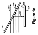
図1e及び図1fには、約50%が反射性372であり、50%が透過性374であるプレート340の例を示す。多くの実施形態は、約60/40%と40/60%との間の範囲を伴う。しかしながら、システム100は、これらの範囲から大きく外れて実装することもできる。
FIGS. 1e and 1f show an example of a
図1g及び図1lには、プレート340を用いて画像880を表示するシステム100の例を示す。図1h及び図1mには、システム100が画像880を表示するために使用されていない間、空間を節約するようにプレート340が折り畳まれる圧縮モード128におけるこのようなプレート340の対応する例を示す。
FIGS. 1 g and 1 l show an example of a
図1nは、プレート340を利用して光800の流れに対する「交通警官」の機能を実行できる異なるアセンブリ及びコンポーネントの例である。
FIG. 1 n is an example of different assemblies and components that can utilize the
II.アセンブリ及びコンポーネント
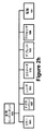
システム100は、システム100の動作をサポートする様々な機能を実行するコンポーネントのアセンブリの面から説明することができる。図2aは、イメージングアセンブリ300に光800を供給する照明アセンブリ200で構成されたシステム100のブロック図である。イメージングアセンブリ300の変調器320は、照明アセンブリ200からの光800を用いて、システム100が表示する画像880を形成する。この図は、画像880を形成する光800の経路から見たものであり、従って光800は、変調器320に到達する前と変調器320を離れた後にプレート340に達するので、イメージングアセンブリ300内ではプレート340が2回出現する。
II. Assembly and
図示のように、システム100は、イメージングアセンブリ300からの画像880を1又は2以上のユーザ90がアクセスできる位置に向ける投影アセンブリ400と、ディスプレイ410とを含むこともできる。イメージングアセンブリ300によって生成された画像880は、システム100によってユーザ90に表示される前に何らかの形で修正されることが多く、従って暫定画像850又は未完成画像850と呼ぶこともできる。
As shown, the
A.照明アセンブリ
照明アセンブリ200は、画像880を表示できるようにシステム100に光800を供給する機能を実行する。照明アセンブリ200は、光800を生成する光源210を含むことができる。照明アセンブリ200は、システム100の他のアセンブリによって使用され処理される光800を生成する。
A. Lighting Assembly The
図2cは、照明アセンブリ200に含めることができる異なるコンポーネントの例を示す階層図である。これらのコンポーネントは、以下に限定されるわけではないが、幅広い光源210、ディフューザアセンブリ280、及び様々な支持コンポーネント150を含むことができる。光源210の例は、以下に限定されるわけではないが、マルチバルブ光源211、LEDランプ212、3色LEDランプ213、レーザ214、OLED215、CFL216、白熱ランプ218、及び角度非依存型ランプ219などを挙げることができる。光源210は、光800が生成され、システム100の残り部分全体を通じて移動する場所である。従って、各光源210は、光800が生み出される場所230である。
FIG. 2 c is a hierarchical diagram illustrating examples of different components that can be included in the
多くの場合、赤色、緑色及び青色の原色毎に1つのLEDが指定される3色LEDランプ213を光源として使用することが望ましい。
In many cases, it is desirable to use as a light source a three-
B.イメージングアセンブリ
イメージングアセンブリ300は、照明アセンブリ200によって供給された光800から画像880を作成する機能を実行する。図2aに示すように、変調器320は、照明アセンブリ200によって供給された光800を、システム100が表示する画像880に変換することができる。図2bに示すように、イメージングアセンブリ300によって生成された画像880は、1又は2以上のユーザ90が体験できる場所に向けられる前に合焦され、又はある程度まで別様に修正することができるので、暫定画像850と呼ぶこともできる。
B. Imaging Assembly The
イメージングアセンブリ300は、画像を形成するために使用される技術のタイプに基づいて大きく変化することができる。イメージングアセンブリ300内の実質的に異なるコンポーネントには、DLP(デジタル光処理)、LCD(液晶ディスプレイ)、LCOS(反射型液晶)などのディスプレイ技術、及びその他の方法が関与することができる。
The
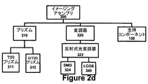
図2fは、システム100のイメージングアセンブリ300において利用できる異なるコンポーネントのいくつかの例を示す階層図である。プリズム310は、変調器320に及び/又は変調器320から光を誘導する上で非常に有用なコンポーネントとすることができる。通常、DLPアプリケーションは、TIRプリズム311又はRTIRプリズム312のアレイを用いてDMD324に及びDMD324から光を誘導する。上述したように、プレート340は、システム100において使用されるプリズム310の必要性に取って代わることができる。
FIG. 2 f is a hierarchical diagram illustrating some examples of different components that may be utilized in the
(光変調器320と呼ばれることもある)変調器320は、光800を修正又は変更し、表示すべき画像880を生成する装置である。変調器320は、変調器320の様々な異なる特性を用いて動作することができる。反射式変調器322は、変調器320の反射特性を用いて、供給された光800から画像880を形成する。反射式変調器322の例としては、以下に限定されるわけではないが、DLPディスプレイのDMD324及びいくつかのLCOS(反射型液晶)パネル340が挙げられる。透過式変調器321は、変調器320の透過特性を用いて、供給された光800から画像880を形成する。透過式変調器321の例としては、以下に限定されるわけではないが、LCDディスプレイのLCD(液晶ディスプレイ)及びいくつかのLCOSパネル340が挙げられる。通常、LCOS又はLCDシステム100のイメージングアセンブリ300は、コンバイナキューブ、又は単一の画像880に異なる単色画像を組み込むための何らかの同様の装置を有する。
Modulator 320 (sometimes referred to as light modulator 320) is a device that modifies or alters light 800 and produces an
イメージングアセンブリ300は、様々な支持コンポーネント150を含むこともできる。
The
C.投影アセンブリ
図2bに示すように、投影アセンブリ400は、ユーザ900が画像880にアクセスできるシステム100内の最終目的地に画像880を誘導するタスクを実行することができる。多くの場合、イメージングアセンブリ300によって作成された画像880は、変調器320による画像880の生成とユーザ90に対する画像880の表示との間で少なくともわずかに修正される。従って、イメージングアセンブリ300の変調器320によって作成された画像880は暫定画像850にすぎず、実際にユーザ90に表示される最終版の画像880ではない。
C. Projection Assembly As shown in FIG. 2 b, the
図2eは、投影アセンブリ400の一部とすることができる異なるコンポーネントの例を示す階層図である。ディスプレイ410は、画像880の最終的な目的地、すなわちユーザ90がアクセスできる画像880の場所及び形態である。ディスプレイ410の例としては、能動的画面412、受動的画面414、接眼部416及びVRD接眼部418を挙げることができる。
FIG. 2 e is a hierarchical diagram illustrating examples of different components that can be part of the
投影アセンブリ400は、後述する様々な支持コンポーネント150を含むこともできる。プレート340は、図2bに示すようにシステム100の異なるコンポーネント間で光800の流れを管理する優れたツールであるため、投影アセンブリ400内のコンポーネントとしての役割を果たすこともできる。
D.センサ/追跡アセンブリ
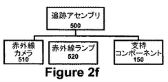
図2bには、(センサアセンブリ500とも呼ばれる)追跡アセンブリ500を含むシステム100の例を示す。センサアセンブリ500は、ユーザ90、ユーザと画像880の相互作用、及び/又はユーザ90及びシステム100が物理的に存在する外部環境に関する情報を取り込むために使用することができる。
D. Sensor / Tracking Assembly FIG. 2b shows an example of a
図2fに示すように、センサアセンブリ500は、通常はビューア96の眼の動きに関する視線追跡属性530を取り込む赤外線カメラなどのカメラであるセンサ510を含むことができる。赤外線カメラの機能をサポートする赤外線光源などのランプ520、及び様々な異なる支持コンポーネント150。追跡アセンブリ500を含むシステム100の多くの実施形態では、追跡アセンブリ500が、部分的透明プレート340と協働する曲面ミラー420の構成などの投影アセンブリ400のコンポーネントを利用する。このような構成を用いて、ビューア96の眼92に画像880を送達すると同時にビューア96の眼92の赤外線画像を取り込むことができる。
As shown in FIG. 2 f, the
センサアセンブリ500は、動作環境80から視覚画像、ビデオ、音声、動き、位置及びその他の情報を取り込むためのセンサ510を含むこともできる。
The
E.拡張アセンブリ
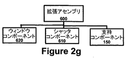
拡張アセンブリ600は、システム100内の開閉可能なウィンドウコンポーネント620(ウィンドウコンポーネント620はシャッタコンポーネント610を含むことができる)を通じて外部環境80からの自然光が侵入できるようにすることができる。
E. Expansion Assembly The
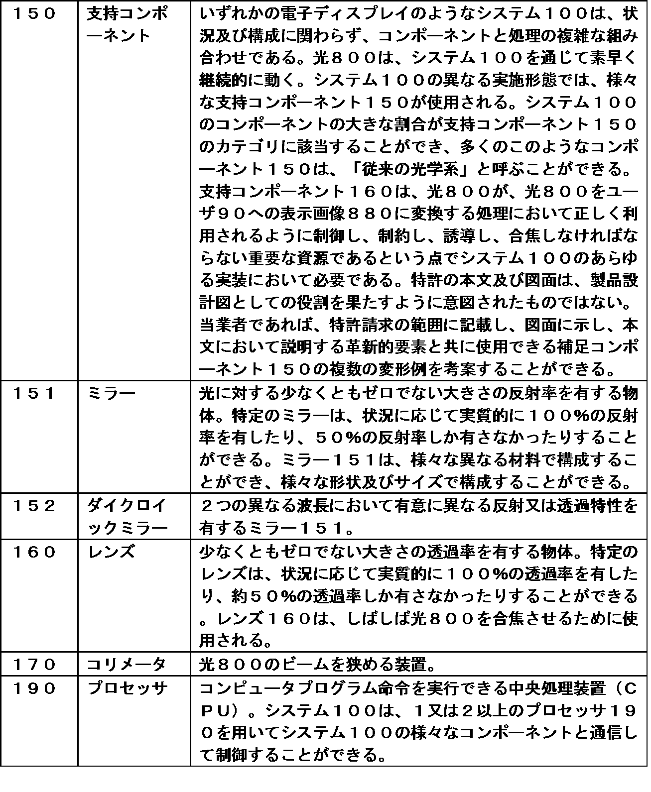
F.支持コンポーネント
光800は、管理が困難な資源となり得る。光800は動きが速く、ほとんどの入力又は原料物質を制約できる方法と同じ方法で制約することができない。図2jは、いくつかの支持コンポーネント150の例を示す階層図であり、これらの多くは従来の光学コンポーネントである。(ダイクロイックミラー152を含む)ミラー141、レンズ160、コリメータ170及びプレート180などの従来の光学コンポーネントには、いずかのディスプレイ技術アプリケーションが伴う。同様に、あらゆる電動装置は電源191を必要とし、画像880を表示できる装置は、プロセッサ190を有する可能性が高い。
F. Supporting
III.VRDバイザーの実施形態
システム100は、DLPシステム141、LCDシステム142及びLCOSシステム143を含む様々な異なるディスプレイ技術140に関して実装することができる。プレート340は、TIRプリズム311及びRTIRプリズム312の代用品として特に有用であると考えられるので、様々な図面は、DLPシステム141に重点を置いている。
III. VRD Visor Embodiments The
図3aは、VRDバイザー装置116の例を示す斜視図である。2つのVRD接眼部418は、画像880をユーザ90の眼に直接投影できるようにする。
FIG. 3 a is a perspective view showing an example of the
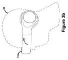
図3bは、VRDバイザー装置116をユーザ90の頭部94に着用した例を示す側面図である。装置116がユーザ90の眼92に画像880を投影する位置にある場合、ユーザ90の眼92は、装置116自体によって塞がれる。
FIG. 3 b is a side view showing an example in which the
図3cは、左眼92用のVRDバイザー装置116の例を示すコンポーネント図である。右眼92には、図3cの鏡像が関連する。
FIG. 3 c is a component diagram illustrating an example of a
3色LED光源213が光を生成し、この光が集光レンズ160を通過し、集光レンズ160が光800をミラー151に向け、ミラー151が光800を成形レンズ160に向けて反射し、その後、光800は、プレート340及びDMD324で構成されたイメージングアセンブリ300に入射する。イメージングアセンブリ300からの暫定画像850は、別のレンズ160を通過し、これらのレンズが暫定画像850を最終画像880に合焦し、接眼部416を通じてユーザ90に見えるようになる。
The three-color
IV.別の実施形態
発明の潜在的な実施形態の全てを言葉又は図面で明確に開示できる特許出願は存在しない。既知の同等物の変形例も非明示的に含まれる。特許法の規定に従い、システム100、方法900及び装置110(まとめて「システム」100)の原理、機能及び動作モードをいくつかの好ましい実施形態の形で説明し図示する。しかしながら、本発明のシステム100は、本発明の思想又は範囲から逸脱することなく、具体的に説明し図示する以外の方法でも実施できると理解しなければならない。
IV. Alternative Embodiments There are no patent applications that can explicitly disclose all potential embodiments of the invention in words or drawings. Variations of known equivalents are also implicitly included. In accordance with the provisions of patent law, the principles, functions and modes of operation of
上述及び後述のシステム100の説明は、本明細書で説明する要素の全ての新規の自明でない別の組み合わせも含むと理解すべきであり、特許請求の範囲は、本出願において提示することも、或いはこれらの要素のあらゆる新規の自明でない組み合わせに対するその後の出願において提示することもできる。さらに、上述した実施形態は例示的なものであり、いずれの単一の特徴又は要素も、本出願又はその後の出願において特許請求できる全ての考えられる組み合わせにとって不可欠なものではない。
It is to be understood that the description of
システム100は、先行技術のディスプレイ技術に対する実質的な改善を表す。従来のディスプレイ技術が広範にわたるのと同様に、システム100も、幅広い異なる形で実装することができる。プリズム340の代わりにプレート340を用いて光800を誘導するという新たな手法は、没入的状況及び拡張的状況において、並びに(ユーザ90からのセンサフィードバックがない)一方向の実施形態及び双方向(ユーザ90からのセンサフィードバック)の実施形態の両方において、様々な異なるディスプレイ技術を利用して様々な異なる規模で実装することができる。
A.規模の変形例
ディスプレイ装置は、様々な異なる規模で実装することができる。(Jacksonville Jaguarsのホームである)EverBanks Fieldの巨大スコアボードは、高さ60フィート、長さ362フィートの、3550万個のLED電球で構成されたディスプレイシステムである。このスコアボードは、数万人もの人々によって同時に見られるように意図されている。この対極にあるAvegant社製のGLYPH(TM)バイザーは、ユーザの頭部に着用されて1人のビューアの眼に視覚画像を直接投影する装置である。これらの連続体の両端間には、様々な異なるディスプレイシステムが存在する。
A. Scale Variations Display devices can be implemented in a variety of different scales. The EverBanks Field giant scoreboard (home of Jacksonville Jaguars) is a display system consisting of 35.5 million LED bulbs, 60 feet high and 362 feet long. This scoreboard is intended to be viewed simultaneously by tens of thousands of people. The ALYGANT GLYPH ™ visor at the opposite end is a device that is worn on the user's head and projects a visual image directly on the eyes of one viewer. There are a variety of different display systems between the ends of these continuums.
システム100は、低コヒーレンスの強化された光を用いてユーザ90に視覚画像808を表示する。システム100は、潜在的に様々な異なる規模で実装することができる。
The
図4aは、一般的にはディスプレイシステムの、具体的にはシステム100の実装規模に関連する様々なカテゴリ及びサブカテゴリを示す階層図である。図4aに示すように、システム100は、大規模システム101として実装することも、又はパーソナルシステム103として実装することもできる。
FIG. 4 a is a hierarchical diagram illustrating various categories and subcategories that are generally associated with a display system, specifically the implementation scale of the
1.大規模システム
大規模システム101は、複数の同時ユーザ90による使用を意図している。大規模システム101の例としては、映画館のプロジェクタ、バー、レストラン又は家庭内の大画面TV、及びその他の同様のディスプレイが挙げられる。大規模システム101は、スタジアムのスコアボード102a、タイムズスクエアのディスプレイ102b、或いは高速道路から離れた広告板などの他の又は大型の屋外ディスプレイなどの巨大システム102というサブカテゴリを含む。
1. Large Scale System
2.パーソナルシステム
パーソナルシステム103は、単一のユーザ90による視聴のために設計されたシステム100の実施形態である。パーソナルシステム103の例としては、デスクトップモニタ103a、ポータブルTV103b、ラップトップモニタ103c、及びその他の同様の装置が挙げられる。パーソナルシステム103のカテゴリは、ニア・アイ・システム104というサブカテゴリも含む。
2. Personal System Personal system 103 is an embodiment of
a.ニア・アイ・システム
ニア・アイ・システム104は、ユーザ90の眼がディスプレイの約12インチ内に存在するパーソナルシステム103のサブカテゴリである。ニア・アイ・システム104としては、タブレットコンピュータ104a、スマートフォン104b、及びカメラ、顕微鏡などの接眼部応用104c、並びにその他の同様の装置が挙げられる。ニア・アイ・システム104のサブカテゴリは、バイザーシステム105というサブカテゴリを含む。
a. Near Eye System The near eye system 104 is a subcategory of the personal system 103 where the user's 90 eye is within approximately 12 inches of the display. The near eye system 104 includes a tablet computer 104a, a smartphone 104b, and an eyepiece application 104c such as a camera and a microscope, and other similar devices. The sub-category of the near eye system 104 includes a subcategory of
b.バイザーシステム
バイザーシステム105は、視覚画像200を表示するシステム100の一部がユーザ90の頭部94に実際に着用されるニア・アイ・システム104のサブカテゴリである。このようなシステム105の例としては、仮想現実バイザー、Google Glass(グーグルグラス)、及びその他の従来のヘッドマウントディスプレイ105aが挙げられる。バイザーシステム105のカテゴリは、VRDバイザーシステム106というサブカテゴリを含む。
b. Visor System The
c.VRDバイザーシステム
VRDバイザーシステム106は、ユーザの眼に視覚画像200が直接投影されるバイザーシステム105の実装である。ビューアの眼に画像を直接投影する技術は、2012年2月6日に出願された「画像生成システム及び画像生成方法(IMAGE GENERATION SYSTEMS AND IMAGE GENERATING METHODS)」(米国特許出願第13/367,261号)という名称の公開特許出願に開示されており、この特許出願の内容は引用により本明細書に組み入れられる。
c. VRD Visor System The
3.統合装置
メディアコンポーネントは、時間と共に区分化され共有化されるようになる傾向がある。照明アセンブリ120が特定のイメージングアセンブリ160に一時的にしか接続されないディスプレイ装置の構想が可能である。しかしながら、システム100の照明アセンブリ120及びイメージングアセンブリ160は、ほとんどの実施形態において、(少なくともユーザ90の実用的見地から)単一の統合装置110に恒久的に組み込まれる。図4bは、装置110の異なるカテゴリ及びサブカテゴリの例を示す階層図である。図4bは、図5aを厳密に反映する。潜在的な装置110の領域は、大型装置111及びパーソナル装置113というカテゴリを含む。大型装置111は、巨大装置112というサブカテゴリを含む。パーソナル装置113のカテゴリは、バイザー装置115というサブカテゴリを含むニア・アイ装置114というサブカテゴリを含む。VRDバイザー装置116は、仮想網膜ディスプレイを実装したバイザー装置115のカテゴリを構成し、すなわちVRDバイザー装置116は、視覚画像200をユーザ90の眼に直接投影する。
3. Integrated devices Media components tend to become segmented and shared over time. A display device concept is possible in which the
図4cは、ユーザ90の頭部94に着用された統合VRDバイザー装置106の形で具体化されたVRDバイザーシステム106の斜視図の例を示す図である。要素92については、図ではユーザ90の眼92が装置116自体によって塞がれているという理由で点線を用いている。
FIG. 4 c shows an example of a perspective view of the
B.ディスプレイ技術の異なるカテゴリ
先行技術は、以下に限定されるわけではないが、DLP(デジタル光処理)、LCD(液晶ディスプレイ)及びLCOS(反射型液晶)を含む様々な異なるディスプレイ技術を含む。図4dは、システム200を実装できる基本ディスプレイ技術に基づく、システム100の異なるカテゴリを示す階層図である。システム100は、DLPシステム141としての使用を意図されているものの、実装手段は明らかに異なり、実装理由は存在しないかもしれないが、潜在的にLCOSシステム143、或いはLCDシステム142として使用することもできる。システム100は、ディスプレイ技術の他のカテゴリ及びサブカテゴリにおいて実装することもできる。
B. Different Categories of Display Technology The prior art includes a variety of different display technologies including, but not limited to, DLP (Digital Light Processing), LCD (Liquid Crystal Display) and LCOS (Reflective Liquid Crystal). FIG. 4d is a hierarchical diagram illustrating different categories of the
C.没入対拡張
図4eは、没入と拡張の違いに基づいてカテゴリに体系化されたシステム100の階層を示す階層図である。システム100のいくつかの実施形態は、様々な異なる動作モード120を有することができる。没入モード121は、システム100がユーザ90に表示しているもののみにユーザ90の焦点が合うように外部世界を遮断する機能を有する。対照的に、拡張モード122は、ユーザ90の物理的環境に重ね合わせた視覚画像200を表示するように意図される。システム100の没入モードと拡張モードの違いは、特にニア・アイ・システム104及びバイザーシステム105の文脈において関連する。
C. Immersion vs. Extension FIG. 4e is a hierarchy diagram showing the hierarchy of the
システム100のいくつかの実施形態は、ユーザ90自身の判断で没入モード又は拡張モードのいずれかで動作するように構成することができる。一方で、システム100の他の実施形態は、単一の動作モード120のみを有することもできる。
Some embodiments of the
D.表示専用対表示/検出/追跡/モニタ
システム100のいくつかの実施形態は、光学情報の一方向伝達のみのために構成される。他の実施形態は、ユーザ90からの情報を視覚画像880として取り込み、潜在的にユーザ90がメディア体験の他の態様にアクセスできるようにすることができる。図4fは、一方向システム124(非検知動作モード124)及び双方向システム123(検知動作モード123)のカテゴリを反映する階層図である。双方向システム123は、網膜スキャニング及びモニタリングなどの機能を含むことができる。ユーザ90を識別することも、ユーザ90の眼92の焦点を追跡することも、他の同様の機能を提供することもできる。一方向システム124には、ユーザ90に関する情報又はユーザ90からの情報を取り込むセンサ又はセンサアレイが存在しない。
D. Some embodiments of the display-only versus display / detect / track /
E.メディアプレーヤ−一体型対分離型
ディスプレイ装置は、メディアプレーヤと一体化されることもある。他の例では、メディアプレーヤがディスプレイ装置から完全に分離される。一例として、ラップトップコンピュータは、単一の統合装置内に、映画を表示する画面、ビデオ画像に伴う音声を伝えるスピーカ、ディスクから離れてソースメディアを再生するDVD又はBLU−RAY(登録商標)プレーヤを含むことができる。このような装置は、ストリーミングを行うこともできる。
E. Media Player—Integrated vs. Separate Display Device may be integrated with a media player. In another example, the media player is completely separated from the display device. As an example, a laptop computer can be a single integrated device with a screen that displays a movie, speakers that carry audio accompanying a video image, a DVD or BLU-RAY® player that plays the source media away from the disc. Can be included. Such devices can also stream.
図4gは、システム100がメディアプレーヤと一体化されているか否かに基づくシステム100の様々な異なるカテゴリを示す階層図である。統合メディアプレーヤシステム107は、実際にメディアコンテンツを再生する能力及び画像880を表示する能力を含む。非統合メディアプレーヤシステム108は、メディアコンテンツを再生するためにメディアプレーヤと通信しなければならない。
FIG. 4g is a hierarchical diagram illustrating various different categories of the
F.ユーザ−ビューア対オペレータ
図4hは、ユーザ90が果たすことができる異なる役割の例を示す階層図である。ビューア96は、画像880にアクセスすることはできるが、それ以外にシステム100の機能を制御することはできない。オペレータ98は、システム100の動作を制御することはできるが、画像880にアクセスすることはできない。映画館で言えば、ビューア96は観客であり、オペレータ98は映画館の従業員である。
F. User-Viewer vs. Operator FIG. 4h is a hierarchy diagram showing examples of different roles that the
G.メディアコンテンツの属性
図4iに示すように、メディアコンテンツ840は、様々な異なるタイプの属性を含むことができる。画像880を表示するシステム100は、視覚属性841を含むメディアコンテンツ840を再生するシステム100である。しかしながら、メディアコンテンツ840の多くの例は、音響属性842、さらには触覚属性も含む。嗅覚属性844を通信するいくつかの新たな技術も存在し、状況によっては、味覚属性845を伝える能力がメディア体験の一部になるのも時間の問題にすぎない。
G. Media Content Attributes As shown in FIG. 4 i,
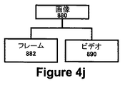
図4jに示すように、いくつかの画像880は、さらに大量のビデオ890コンテキストの一部である。他のコンテキストでは、画像880を、単独型静止フレーム882とすることもできる。
As shown in FIG. 4j, some
VI.用語集/定義
表1に、要素番号、要素名及び要素の定義/説明を相関付けたチャートを示す。
100 システム
200 照明アセンブリ
324 DMD
340 プレート
400 投影アセンブリ
800 光
100
340
Claims (20)
前記複数の光(800)を生成する照明アセンブリ(200)と、
前記複数の光(800)から前記画像(880)を生成するイメージングアセンブリ(300)と、
を備え、前記イメージングアセンブリ(300)は、
前記光(800)を前記画像(880)に変調するDMD(324)と、
前記照明アセンブリ(200)からの前記光(800)を前記DMD(324)に向け、前記DMD(324)からの前記光(800)をディスプレイ(410)に向けるプレート(340)と、
を含む、
ことを特徴とするシステム(100)。 A system (100) for displaying an image (880) composed of a plurality of lights (800) on a viewer (96),
An illumination assembly (200) for generating the plurality of lights (800);
An imaging assembly (300) for generating the image (880) from the plurality of lights (800);
The imaging assembly (300) comprises:
A DMD (324) that modulates the light (800) into the image (880);
A plate (340) for directing the light (800) from the illumination assembly (200) to the DMD (324) and directing the light (800) from the DMD (324) to a display (410);
including,
The system (100) characterized by the above.
請求項1に記載のシステム(100)。 The plate (340) includes an aperture (350),
The system (100) of claim 1.
請求項1に記載のシステム(100)。 The plate (340) includes a plastic film (344),
The system (100) of claim 1.
請求項1に記載のシステム(100)。 The plate (340) includes a plastic film (344) that modifies the light (800) to form a desired optical effect (860) when forming the image (880). The resulting modulation film (345),
The system (100) of claim 1.
請求項1に記載のシステム(100)。 The plate (340) is composed of a plurality of films (344), and the plate (340) is not composed of glass (342).
The system (100) of claim 1.
請求項1に記載のシステム(100)。 The plate (340) includes a plurality of modulation films (345) that define a dynamic aperture (352),
The system (100) of claim 1.
請求項1に記載のシステム(100)。 The system (100) is a visor device (115) including an eyepiece (416), and the eyepiece (416) includes the display (410).
The system (100) of claim 1.
請求項1に記載のシステム(100)。 The plate (340) includes a plastic film (344) having an adjustable diffraction gradient (364).
The system (100) of claim 1.
請求項1に記載のシステム(100)。 The plate (340) includes glass (342) and plastic film (344).
The system (100) of claim 1.
請求項1に記載のシステム(100)。 The plate (340) has reflectivity (371) associated with the full spectrum (802),
The system (100) of claim 1.
請求項1に記載のシステム(100)。 The plate (340) has reflectivity (371) characteristic of the partial spectrum (805),
The system (100) of claim 1.
請求項1に記載のシステム(100)。 The plate (340) enables polarization (373) of the light (800),
The system (100) of claim 1.
請求項1に記載のシステム(100)。 The plate (340) is a microlens array (380).
The system (100) of claim 1.
請求項1に記載のシステム(100)。 The plate (340) is a folding plate (390) that can be folded into a small-capacity space when not in use.
The system (100) of claim 1.
前記複数の光(800)をイメージングアセンブリ(300)に供給する、光源(210)を含む照明アセンブリ(200)と、
前記光(800)を暫定画像(850)に変調する前記メージングアセンブリ(300)と、
を備え、前記メージングアセンブリ(300)は、
前記光(800)を前記暫定画像(850)に変調するDMD(324)と、
前記照明アセンブリ(200)からの前記光(800)を前記DMD(324)に向け、前記DMD(324)からの前記光(800)を前記投影アセンブリ(400)に向けるプレート(340)と、
を含み、前記システムは、
前記暫定画像(850)からの前記画像(880)をディスプレイ(410)上に表示する投影アセンブリ(400)をさらに備える、
ことを特徴とするシステム(100)。 A system (100) for displaying an image (880) composed of a plurality of lights (800) on a viewer (96),
An illumination assembly (200) including a light source (210) for supplying the plurality of lights (800) to the imaging assembly (300);
The merging assembly (300) for modulating the light (800) into a provisional image (850);
And the merging assembly (300) comprises:
A DMD (324) that modulates the light (800) into the provisional image (850);
A plate (340) for directing the light (800) from the illumination assembly (200) to the DMD (324) and directing the light (800) from the DMD (324) to the projection assembly (400);
The system includes:
A projection assembly (400) for displaying the image (880) from the provisional image (850) on a display (410);
The system (100) characterized by the above.
請求項15に記載のシステム(100)。 The system (100) is a VRD visor device (116), and the display (410) is part of the eyepiece (416) of the VRD visor device (116).
The system (100) of claim 15.
請求項15に記載のシステム(100)。 The plate (430) includes a glass (342) and a plurality of plastic films (344), the plastic film (344) being a first plastic film (344) on a first side of the glass (342). And a second plastic film (344) on the second side of the glass (342),
The system (100) of claim 15.
請求項15に記載のシステム(100)。 The plate (340) includes an aperture (350) and a plastic film (344), the plastic film (344) modifying the light (800) to produce the desired optical effect (860). (345),
The system (100) of claim 15.
請求項15に記載のシステム(100)。 The plate (340) includes a plurality of modulation films (345) defining a dynamic aperture (352) and a plastic film (344) having an adjustable diffraction gradient (364).
The system (100) of claim 15.
光源(210)によって前記複数の光(800)を生成するステップ(910)と、
プレート(340)によって前記光(800)をDMD(324)に向けて反射するステップ(922)と、
前記DMD(324)によって前記複数の光(800)を暫定画像(850)に変調するステップ(924)と、
前記プレート(340)によって前記暫定画像(850)内の前記光(800)をディスプレイ(410)に向けて透過するステップ(926)と、
を含むことを特徴とする方法(900)。 A method (900) of displaying an image (880) composed of light (800) in a viewer (96) using a plate (430), comprising:
Generating (910) the plurality of lights (800) by a light source (210);
Reflecting (922) the light (800) by the plate (340) towards the DMD (324);
Modulating (924) the plurality of lights (800) into a provisional image (850) by the DMD (324);
Transmitting (926) the light (800) in the provisional image (850) toward the display (410) by the plate (340);
A method (900) comprising:
Applications Claiming Priority (7)
| Application Number | Priority Date | Filing Date | Title |
|---|---|---|---|
| US201461994997P | 2014-05-19 | 2014-05-19 | |
| US61/994,997 | 2014-05-19 | ||
| US14/590,953 US20170139209A9 (en) | 2014-01-06 | 2015-01-06 | System, method, and apparatus for displaying an image using a curved mirror and partially transparent plate |
| US14/590,953 | 2015-01-06 | ||
| US14/678,974 US20170068311A1 (en) | 2015-04-04 | 2015-04-04 | System, apparatus, and method for selectively varying the immersion of a media experience |
| US14/678,974 | 2015-04-04 | ||
| PCT/US2015/031649 WO2015179455A2 (en) | 2014-05-19 | 2015-05-19 | Apparatus, system, and method for displaying an image using a plate |
Publications (1)
| Publication Number | Publication Date |
|---|---|
| JP2017523480A true JP2017523480A (en) | 2017-08-17 |
Family
ID=54554960
Family Applications (1)
| Application Number | Title | Priority Date | Filing Date |
|---|---|---|---|
| JP2017513599A Pending JP2017523480A (en) | 2014-05-19 | 2015-05-19 | Image display apparatus, system and method using plate |
Country Status (4)
| Country | Link |
|---|---|
| EP (1) | EP3146389A4 (en) |
| JP (1) | JP2017523480A (en) |
| CN (1) | CN106605171A (en) |
| WO (1) | WO2015179455A2 (en) |
Families Citing this family (4)
| Publication number | Priority date | Publication date | Assignee | Title |
|---|---|---|---|---|
| CN107589546A (en) * | 2017-10-23 | 2018-01-16 | 北京小米移动软件有限公司 | Optical system and augmented reality glasses |
| CN110133859B (en) | 2018-02-09 | 2021-09-03 | 中强光电股份有限公司 | Display device |
| CN110133860B (en) * | 2018-02-09 | 2022-01-25 | 中强光电股份有限公司 | Display device |
| US11693248B1 (en) | 2022-01-20 | 2023-07-04 | Microsoft Technology Licensing, Llc | TIR prisms and use of backlight for LCoS microdisplay illumination |
Family Cites Families (17)
| Publication number | Priority date | Publication date | Assignee | Title |
|---|---|---|---|---|
| US6097543A (en) * | 1992-02-07 | 2000-08-01 | I-O Display Systems Llc | Personal visual display |
| US6652105B1 (en) * | 2001-11-30 | 2003-11-25 | Infocus Corporation | Reflective light valve-based multimedia projector employing a patterned-silvered mirror |
| US7283112B2 (en) * | 2002-03-01 | 2007-10-16 | Microsoft Corporation | Reflective microelectrical mechanical structure (MEMS) optical modulator and optical display system |
| US7320826B2 (en) * | 2003-03-20 | 2008-01-22 | Ppg Industries Ohio, Inc. | Photochromic articles with reduced temperature dependency and methods for preparation |
| WO2005015894A2 (en) * | 2003-08-08 | 2005-02-17 | Eclipse Video Technology Llc | Method and apparatus for increasing effective contrast ratio and brightness yields for digital light valve image projectors |
| JP2006023441A (en) * | 2004-06-07 | 2006-01-26 | Kazuji Yoshida | Image display apparatus |
| US20070081248A1 (en) * | 2005-10-11 | 2007-04-12 | Kuohua Wu | Reflector |
| US7486341B2 (en) * | 2005-11-03 | 2009-02-03 | University Of Central Florida Research Foundation, Inc. | Head mounted display with eye accommodation having 3-D image producing system consisting of, for each eye, one single planar display screen, one single planar tunable focus LC micro-lens array, one single planar black mask and bias lens |
| US7483200B1 (en) * | 2008-01-14 | 2009-01-27 | Spatial Photonics, Inc. | Multiple stop micro-mirror array display |
| JP5201580B2 (en) * | 2008-06-06 | 2013-06-05 | 新オプトウエア株式会社 | Hologram creation device and hologram printer |
| US7926951B2 (en) * | 2008-07-11 | 2011-04-19 | Eastman Kodak Company | Laser illuminated micro-mirror projector |
| US20110044046A1 (en) * | 2009-04-21 | 2011-02-24 | Abu-Ageel Nayef M | High brightness light source and illumination system using same |
| US20130314303A1 (en) * | 2010-02-28 | 2013-11-28 | Osterhout Group, Inc. | Ar glasses with user action control of and between internal and external applications with feedback |
| JP5968925B2 (en) * | 2011-03-14 | 2016-08-10 | ドルビー ラボラトリーズ ライセンシング コーポレイション | Projector, projection system and related method using laser light source for 3D projection and color gamut improvement |
| JP5811491B2 (en) * | 2011-04-12 | 2015-11-11 | 株式会社ニコン | Microscope and its program |
| WO2013036789A1 (en) * | 2011-09-09 | 2013-03-14 | University Of Connecticut | Electrochromic devices prepared from the in situ formation of conjugated polymers |
| US8982014B2 (en) * | 2012-02-06 | 2015-03-17 | Battelle Memorial Institute | Image generation systems and image generation methods |
-
2015
- 2015-05-19 JP JP2017513599A patent/JP2017523480A/en active Pending
- 2015-05-19 WO PCT/US2015/031649 patent/WO2015179455A2/en active Application Filing
- 2015-05-19 CN CN201580013343.4A patent/CN106605171A/en active Pending
- 2015-05-19 EP EP15795835.6A patent/EP3146389A4/en not_active Withdrawn
Also Published As
| Publication number | Publication date |
|---|---|
| EP3146389A2 (en) | 2017-03-29 |
| EP3146389A4 (en) | 2018-09-19 |
| WO2015179455A2 (en) | 2015-11-26 |
| WO2015179455A3 (en) | 2016-01-21 |
| CN106605171A (en) | 2017-04-26 |
Similar Documents
| Publication | Publication Date | Title |
|---|---|---|
| US10409079B2 (en) | Apparatus, system, and method for displaying an image using a plate | |
| US9995857B2 (en) | System, apparatus, and method for displaying an image using focal modulation | |
| US9823474B2 (en) | System, apparatus, and method for displaying an image with a wider field of view | |
| US20160195718A1 (en) | System, method, and apparatus for displaying an image using multiple diffusers | |
| TWI448804B (en) | Illumination system and projection device comprising the same | |
| US8905548B2 (en) | Device and method for reducing speckle in projected images | |
| US20170139209A9 (en) | System, method, and apparatus for displaying an image using a curved mirror and partially transparent plate | |
| US20170068311A1 (en) | System, apparatus, and method for selectively varying the immersion of a media experience | |
| US20160292921A1 (en) | System, apparatus, and method for displaying an image using light of varying intensities | |
| US8599297B2 (en) | Multi-dimensional imaging system and method | |
| US10598949B2 (en) | Method and apparatus for forming a visible image in space | |
| TW200526987A (en) | Display device and display method | |
| JP2017523480A (en) | Image display apparatus, system and method using plate | |
| US20160198133A1 (en) | System, method, and apparatus for displaying an image with reduced color breakup | |
| JP2020187165A (en) | Image projection device | |
| TWI444750B (en) | Color wheel module for use in a projector apparatus, projector apparatus, and method of switching display for a stereoscopic image or a flat image | |
| JP2017511496A (en) | Imaging curved mirrors and partially transparent plates | |
| JP2006189700A (en) | Projector and rear projection type display apparatus | |
| JP2009288407A (en) | Lighting optical system and image projection apparatus | |
| TWI476447B (en) | Stereoscopic projection display apparatus | |
| KR20080053792A (en) | Projector with laser source | |
| TWI460526B (en) | Projector | |
| JP2010271505A (en) | Stereoscopic display device | |
| JP2005165319A (en) | Reflection type micro display projection system | |
| JP2010282813A (en) | Illumination device and projector using the same |