JP2017523104A - Web guide apparatus and apparatus for processing material webs - Google Patents
Web guide apparatus and apparatus for processing material webs Download PDFInfo
- Publication number
- JP2017523104A JP2017523104A JP2017506840A JP2017506840A JP2017523104A JP 2017523104 A JP2017523104 A JP 2017523104A JP 2017506840 A JP2017506840 A JP 2017506840A JP 2017506840 A JP2017506840 A JP 2017506840A JP 2017523104 A JP2017523104 A JP 2017523104A
- Authority
- JP
- Japan
- Prior art keywords
- web
- spindle
- web guide
- guide device
- fixing element
- Prior art date
- Legal status (The legal status is an assumption and is not a legal conclusion. Google has not performed a legal analysis and makes no representation as to the accuracy of the status listed.)
- Granted
Links
- 239000000463 material Substances 0.000 title claims abstract description 59
- 238000004049 embossing Methods 0.000 claims description 6
- 239000013536 elastomeric material Substances 0.000 description 5
- 230000001133 acceleration Effects 0.000 description 1
- 238000010276 construction Methods 0.000 description 1
- 238000001514 detection method Methods 0.000 description 1
- 238000012986 modification Methods 0.000 description 1
- 230000004048 modification Effects 0.000 description 1
- 230000007935 neutral effect Effects 0.000 description 1
Images


Classifications
-
- B—PERFORMING OPERATIONS; TRANSPORTING
- B65—CONVEYING; PACKING; STORING; HANDLING THIN OR FILAMENTARY MATERIAL
- B65H—HANDLING THIN OR FILAMENTARY MATERIAL, e.g. SHEETS, WEBS, CABLES
- B65H23/00—Registering, tensioning, smoothing or guiding webs
- B65H23/02—Registering, tensioning, smoothing or guiding webs transversely
- B65H23/032—Controlling transverse register of web
- B65H23/038—Controlling transverse register of web by rollers
-
- B—PERFORMING OPERATIONS; TRANSPORTING
- B41—PRINTING; LINING MACHINES; TYPEWRITERS; STAMPS
- B41F—PRINTING MACHINES OR PRESSES
- B41F21/00—Devices for conveying sheets through printing apparatus or machines
-
- B—PERFORMING OPERATIONS; TRANSPORTING
- B65—CONVEYING; PACKING; STORING; HANDLING THIN OR FILAMENTARY MATERIAL
- B65H—HANDLING THIN OR FILAMENTARY MATERIAL, e.g. SHEETS, WEBS, CABLES
- B65H23/00—Registering, tensioning, smoothing or guiding webs
- B65H23/04—Registering, tensioning, smoothing or guiding webs longitudinally
- B65H23/16—Registering, tensioning, smoothing or guiding webs longitudinally by weighted or spring-pressed movable bars or rollers
-
- B—PERFORMING OPERATIONS; TRANSPORTING
- B65—CONVEYING; PACKING; STORING; HANDLING THIN OR FILAMENTARY MATERIAL
- B65H—HANDLING THIN OR FILAMENTARY MATERIAL, e.g. SHEETS, WEBS, CABLES
- B65H23/00—Registering, tensioning, smoothing or guiding webs
- B65H23/04—Registering, tensioning, smoothing or guiding webs longitudinally
- B65H23/26—Registering, tensioning, smoothing or guiding webs longitudinally by transverse stationary or adjustable bars or rollers
Landscapes
- Registering, Tensioning, Guiding Webs, And Rollers Therefor (AREA)
- Preliminary Treatment Of Fibers (AREA)
- Replacement Of Web Rolls (AREA)
Abstract
本発明は、第1及び第2のフレームエレメント(31,32)を備えた、材料ウエブ(2)、特に、フィルムウエブをガイドするためのウエブガイド装置(3)に関する。第1及び第2のフレームエレメント(31,32)は、各々の第1の端部領域(311,321)が第1のスピンドル(33)に回動可能に取り付けられており、各々の第2の端部領域(321,322)においてウエブガイドローラ(34)を介して互いに連結されており、固定エレメント(37)を介して上記第1のスピンドル(33)に連結された第2のスピンドル(35)に連結されている。The invention relates to a material web (2), in particular a web guide device (3) for guiding a film web, comprising first and second frame elements (31, 32). Each of the first and second frame elements (31, 32) has a first end region (311, 321) rotatably attached to the first spindle (33). Are connected to each other via web guide rollers (34) in the end regions (321, 322) of the second spindle (33) connected to the first spindle (33) via a fixing element (37). 35).
Description
本発明は、材料ウエブ、特にフィルムウエブを案内するウエブガイド装置及び材料ウエブ、特にフィルムウエブを処理する装置に関する。 The present invention relates to a web guide device for guiding a material web, in particular a film web, and an apparatus for processing a material web, in particular a film web.
エンボス装置、プリント装置等において、例えば、フィルムウエブ又はペーパーウエブなどの材料ウエブを処理する間、材料ウエブは、一般的に、リール上に配置され、処理のために引き出され、偏向ローラを介して処理位置に案内され、次いで、再び巻き戻されることがある。 While processing material webs, such as film webs or paper webs, in embossing devices, printing devices, etc., the material webs are generally placed on a reel, pulled out for processing, via a deflection roller It may be guided to the processing position and then rewound again.
新しいリールが設けられたときに、材料ウエブが斜めに又は非対称に引き出された場合、異なる張力が材料ウエブの双方の側縁領域に加わり、これにより、材料ウエブにしわ、折れ目又は裂け目が生じてしまうことがある。 When a new reel is provided, if the material web is pulled diagonally or asymmetrically, different tensions are applied to both side edge regions of the material web, thereby causing wrinkling, creases or tears in the material web. May end up.
しかし、例えば、材料ウエブの1つの端部領域が高い張力下にあることを保証するため、かつ、特に、レジスターマークなどの正確な読み取りを可能にするために、材料ウエブの非対称の(傾斜した)引き出しが望ましい場合もある。 However, for example, to ensure that one end region of the material web is under high tension and in particular to allow an accurate reading of register marks etc., the material web's asymmetric (tilted) ) Drawers may be desirable.
材料ウエブの非対称の引き出しを望むか望まないかに関わらず、上記した欠点を回避するために、非対称をできる限り迅速に修正することが必要である。 Regardless of whether or not an asymmetric withdrawal of the material web is desired or not, it is necessary to correct the asymmetry as quickly as possible in order to avoid the disadvantages mentioned above.
傾斜した引き出しを補正するために一体型の差動歯車を有するウエブガイドローラが周知である。さらに、傾斜した引き出しの検出、及び、例えば、空気式、水圧式又は電気式の調節シリンダなどの能動的な調節装置によるウエブガイドの能動的な修正も周知である。しかし、そのような装置は複雑かつ高価であるとともに、故障し易い。 Web guide rollers with integral differential gears to correct tilted drawers are well known. In addition, the detection of tilted drawers and the active correction of the web guide by means of active adjusting devices such as pneumatic, hydraulic or electric adjusting cylinders are also known. However, such devices are complex and expensive and are prone to failure.
さらに、例えば、完全な円形でないリールにより、ウエブがまっすぐに引き出されたときに生じ得る対称的なウエブの張力を補正するためのいわゆるダンサーローラが周知である。変動するウエブの引張応力下において、ローラは、延長方向に対して垂直に振動し、引張応力が補正される。しかし、上記ローラは、傾斜した引き出しの補正には適していない。 Furthermore, so-called dancer rollers are known for correcting symmetrical web tensions which can occur when the web is pulled straight, for example by means of a non-round reel. Under varying web tensile stress, the roller vibrates perpendicular to the direction of extension and the tensile stress is corrected. However, the roller is not suitable for correcting the tilted drawer.
したがって、本発明の目的は、ウエブガイド装置及び材料ウエブを処理する装置を提供し、これにより、傾斜した材料ウエブの引き出しを、費用対効果が高く、簡単かつ確実に修正することである。 Accordingly, it is an object of the present invention to provide a web guide device and a device for processing a material web, whereby the tilted material web withdrawal is cost-effective, simple and reliable.
上記の目的は、請求項1に記載の特徴を有するウエブガイド装置及び請求項13に記載の特徴を有する材料ウエブを処理する装置により実現することができる。 The above object can be achieved by a web guide device having the features of claim 1 and an apparatus for processing a material web having the features of claim 13.
材料ウエブ、特にフィルムウエブを案内するためのウエブガイド装置は、第1及び第2のフレームエレメントを備え、
第1及び第2のフレームエレメントは、
各々の第1の端部領域において第1のスピンドルに回動可能に取り付けられており、
回転可能に取り付けられたウエブガイドローラを介して、各々の第2の端部領域において互いに連結されており、
固定エレメントを介して第1のスピンドルに連結された第2のスピンドルを介して互いに連結されている。
A web guide device for guiding a material web, in particular a film web, comprises first and second frame elements,
The first and second frame elements are:
Each first end region is pivotally attached to a first spindle;
Connected to each other in each second end region via a web guide roller which is rotatably mounted,
They are connected to each other via a second spindle which is connected to the first spindle via a fixed element.
材料ウエブの対称的なウエブの張力を補正するためだけに(すなわち、傾斜せず、対称的に進行する材料ウエブのために)設計された従来のダンサーローラと比較して、材料ウエブが傾斜して引き出されたときに生じ得る非対称に作用する力に対して適用される特徴は、第2のスピンドル及び固定エレメントによって形成される。スピンドルは、他の構成要素の回転運動をサポートする構成要素である。複数のスピンドルの断面は円形としてもよいし、異なっていてもよく、すなわち、1つのスピンドルの長手方向に沿って断面形状が変化するように形成してもよい。 Compared to conventional dancer rollers designed only to compensate for the symmetric web tension of the material web (i.e., for material webs that do not tilt but travel symmetrically), the material web is tilted. The features applied to the asymmetrically acting forces that can occur when pulled out are formed by the second spindle and the fixing element. The spindle is a component that supports the rotational movement of other components. The cross-sections of the plurality of spindles may be circular or different, that is, they may be formed so that the cross-sectional shape changes along the longitudinal direction of one spindle.
材料ウエブの一方の側縁部に面するウエブガイドローラの一方の側面に作用する張力が他方の側面に作用する張力よりも大きい場合、結果として、固定エレメントを中心としてトルクが生じる。これにより、スピンドル、フレームエレメント及びウエブガイドローラによって形成されるフレームのねじれが固定エレメントを中心に生じる。このため、ウエブガイドローラは、より大きな張力の方向に偏向する。したがって、より大きな張力を受けやすい材料ウエブの側面が解放され、傾斜した引き出しにより生じる非対称が補正される。 If the tension acting on one side of the web guide roller facing one side edge of the material web is greater than the tension acting on the other side, a torque is produced around the fixed element as a result. Thereby, the torsion of the frame formed by the spindle, the frame element, and the web guide roller occurs around the fixed element. For this reason, the web guide roller is deflected in the direction of a larger tension. Thus, the side of the material web that is subject to greater tension is released, and the asymmetry caused by the tilted drawer is corrected.
したがって、補正された張力下では、材料ウエブはウエブガイドローラをまっすぐな状態に留める。このため、外部の制御装置(すなわち、外部センサ及び/又は制御エレメント)が不要となる。ウエブの進行の修正に必要な力は、材料ウエブの張力により利用可能となる。 Thus, under the corrected tension, the material web keeps the web guide roller straight. This eliminates the need for an external control device (ie, an external sensor and / or control element). The force required to correct the web progress is made available by the tension of the material web.
フレームエレメント及び/又は第2のスピンドルが柔軟性を有するように設計されている場合、所望とするウエブガイド装置のねじれを実現することができる。適切な材料の選択及び特定の処理装置において生じる張力に応じて材料強度を調節することにより、要求される柔軟性が得られる。 If the frame element and / or the second spindle is designed to be flexible, the desired twist of the web guide device can be achieved. The required flexibility is obtained by adjusting the material strength in response to the selection of the appropriate material and the tension produced in the particular processing equipment.
例えば、フレームエレメント及び/又はフレームエレメントの第2のスピンドルは、単一部材又は複数の部品として、一つ又は複数のエラストマー材料から形成され得る。また、フレームエレメント及び/又は第2のスピンドルの一部をエラストマー材料から形成して、要求される柔軟性を提供するようにしてもよい。例えば、フレームエレメントと第2のスピンドルとの間の接続箇所、及び/又はフレームエレメントとウエブガイドローラとの間の接続箇所をエラストマー製のベアリングエレメント又は部分的にエラストマーを用いたベアリングエレメントから形成してもよい。あるいは、第2のスピンドルだけをエラストマー系の本質的にねじれ可能な材料から形成し、かつ/又は、第2のスピンドルをエラストマー材料及び/又は非エラストマー系材料からなるねじれた又は撚られた部分的なエレメントから形成してもよい。第2のスピンドルの全体構成におけるエラストマー材料の割合及び/又はエラストマー材料の弾力性は、第2のスピンドルの全体的なねじれ性を決定し、したがって、本発明によるウエブガイド装置の柔軟性の設定を可能とする。 For example, the frame element and / or the second spindle of the frame element may be formed from one or more elastomeric materials as a single member or as a plurality of parts. Also, a portion of the frame element and / or the second spindle may be formed from an elastomeric material to provide the required flexibility. For example, the connection point between the frame element and the second spindle and / or the connection point between the frame element and the web guide roller is formed from an elastomeric bearing element or a partly elastomeric bearing element. May be. Alternatively, only the second spindle is formed from an elastomeric, essentially twistable material, and / or the second spindle is a twisted or twisted partial made of an elastomeric material and / or a non-elastomeric material You may form from an element. The proportion of the elastomeric material in the overall configuration of the second spindle and / or the elasticity of the elastomeric material determines the overall torsion of the second spindle and thus the flexibility setting of the web guide device according to the invention. Make it possible.
しかし、別の実施例として、ウエブガイドローラ及び/又は第2のスピンドルが回転ベアリングによってフレームエレメントに取り付けられることは便宜である。 However, as another example, it is expedient for the web guide roller and / or the second spindle to be attached to the frame element by means of a rotating bearing.
上記の回転ベアリングにより、軸受点を中心としたウエブガイドローラ又は第2のスピンドルの回転が可能となるとともに、不要な材料応力なしに装置のねじれが可能となる。これにより、装置の寿命が増加する。 The rotary bearing enables the web guide roller or the second spindle to rotate around the bearing point and allows the apparatus to be twisted without unnecessary material stress. This increases the life of the device.
さらに、好ましくは、回転ベアリングは、回転ボールベアリングとして形成されている。したがって、ベアリングの簡素でかつ安定した構成によって全ての必要な自由度がもたらされる。 Furthermore, preferably the rotary bearing is formed as a rotary ball bearing. Thus, all necessary degrees of freedom are provided by a simple and stable construction of the bearing.
さらに、第2のスピンドルが第1のスピンドルとウエブガイドローラとの間に配置されていることが有利である。装置の横断方向に延びる他の2つの構成要素の間に第2のスピンドルを配置することにより、固定エレメントと協働して所望とする力点が形成される。 Furthermore, it is advantageous that the second spindle is arranged between the first spindle and the web guide roller. By placing the second spindle between two other components extending in the transverse direction of the device, a desired force point is formed in cooperation with the fixing element.
第2のスピンドルから第1のスピンドルまでの距離と、第2のスピンドルからウエブガイドローラまでの距離との比は、1:3〜1:10であり、好ましくは1:4〜1:7であり、より好ましくは1:5〜1:6であることが特に便宜である。 The ratio of the distance from the second spindle to the first spindle and the distance from the second spindle to the web guide roller is 1: 3 to 1:10, preferably 1: 4 to 1: 7. It is particularly expedient, more preferably 1: 5 to 1: 6.
第2のスピンドルは、ウエブガイドローラよりも第1のスピンドルに近接して配置されていることが望ましい。 The second spindle is preferably arranged closer to the first spindle than the web guide roller.
さらに、固定エレメントは、第1のスピンドル上を軸方向に移行可能に配置されていることが有利である。前述した張力の補正は、第1及び第2のスピンドルに関して固定エレメントの中央位置に対して対称的に生じる。固定エレメントが中央位置から移動した場合、フィルムウエブの対向する側面に非対称の張力がもたらされ、この場合、ウエブガイドローラの対向する側面と固定エレメントとの間においてレバーのストロークが異なるようになる。 Furthermore, the fixing element is advantageously arranged so as to be able to move axially on the first spindle. The aforementioned tension correction occurs symmetrically with respect to the central position of the stationary element with respect to the first and second spindles. When the fixing element is moved from the central position, an asymmetric tension is brought about on the opposite side of the film web, in which case the lever stroke is different between the opposite side of the web guide roller and the fixing element. .
所望とする固定エレメントの設定を確実に行うことができるように、固定エレメントは、固定要素により第1のスピンドルに固定されていることが便宜である。 It is convenient for the fixing element to be fixed to the first spindle by the fixing element so that the desired fixing element can be set reliably.
ウエブガイド装置の運転位置において、固定エレメントは、第1のフレームエレメントと第2のフレームエレメントとの間で第1のスピンドルの中央に固定されていることが望ましい。これにより、材料ウエブがウエブガイドローラを横断方向の応力から解放するように、前述した非対称の張力を完全に補正することが可能となる。中央位置とは、固定エレメントとフレームエレメントとの間の距離が20%を超えない程度、好ましくは10%を超えない程度であることを意味している。 In the operation position of the web guide device, the fixing element is preferably fixed at the center of the first spindle between the first frame element and the second frame element. This makes it possible to completely correct the aforementioned asymmetric tension so that the material web releases the web guide roller from transverse stresses. The center position means that the distance between the fixed element and the frame element does not exceed 20%, preferably does not exceed 10%.
さらに、固定エレメントは、第2のスピンドル上において浮動した状態で取り付けられていることが好ましい。これにより、過度の応力を受けることなく、所望とする装置のねじれが促進される。 Furthermore, the fixing element is preferably mounted in a floating state on the second spindle. Thereby, the twist of the desired apparatus is accelerated | stimulated, without receiving an excessive stress.
固定エレメントがベアリングブッシュを介して第2のスピンドルに取り付けられていることが特に便宜である。これにより、傾き等が生じることなく、確実な固定エレメントの滑りが可能となる。 It is particularly expedient for the fixing element to be attached to the second spindle via a bearing bush. As a result, the fixed element can be reliably slid without any inclination.
ベアリングブッシュの内径は、第2のスピンドルの外径よりも、5%〜20%、好ましくは10%〜12%大きい。これにより、ベアリングブッシュの動きの余地が設定されるとともに、装置のねじれが容易になる。 The inner diameter of the bearing bush is 5% to 20%, preferably 10% to 12% larger than the outer diameter of the second spindle. Thereby, the room for the movement of the bearing bush is set, and the device is easily twisted.
さらなる固定要素により、固定エレメントと第2のスピンドルとの間に摺動抵抗が設定されることはさらに有利である。したがって、ウエブガイドローラに伝わる変動する力に対して装置のねじれをどの程度迅速に追従させるかを設定することが可能となり、これにより、装置の振動を選択的に減衰させるか、あるいは完全に回避することができる。 It is further advantageous that a sliding resistance is set between the fixing element and the second spindle by means of a further fixing element. Therefore, it is possible to set how quickly the twist of the device follows the fluctuating force transmitted to the web guide roller, so that the vibration of the device can be selectively damped or completely avoided. can do.
材料ウエブを処理する装置が前述した形式のウエブガイド装置である場合、ウエブガイド装置の第1のスピンドルが装置のフレームに堅固に固定されていることが便宜である。これにより、非対称的な張力によってウエブガイド装置のねじれが生じたときに材料ウエブに対する所望とするウエブガイドローラの相対的な動きが可能となる。 If the device for processing the material web is a web guide device of the type described above, it is expedient for the first spindle of the web guide device to be firmly fixed to the frame of the device. This allows the desired movement of the web guide roller relative to the material web when the web guide device twists due to asymmetric tension.
さらに、アイドル状態、及び/又はウエブガイドローラに対して対称的に力を付与する状態において、ウエブガイド装置のウエブガイドローラが材料ウエブの進行方向に対して直交して配置され、かつ材料ウエブの進行平面上に位置するように、ウエブガイド装置が配置されていることが有利である。したがって、この状態では、ウエブガイド装置により望ましくない力が材料ウエブに伝達されない。 Furthermore, the web guide roller of the web guide device is arranged perpendicular to the direction of travel of the material web in the idle state and / or in the state of applying a force symmetrically to the web guide roller, and the material web The web guide device is advantageously arranged so that it lies on the plane of travel. Therefore, in this state, an undesirable force is not transmitted to the material web by the web guide device.
装置は、エンボス装置、特にホットエンボス装置、及び/又はプリント装置として、形成されていることが好ましい。本発明の原理について説明してきたが、本発明は、材料ウエブを処理する全ての形式の装置に適用することができる。 The device is preferably formed as an embossing device, in particular a hot embossing device and / or a printing device. Having described the principles of the present invention, the present invention is applicable to all types of apparatus for processing material webs.
以下において、実施例を参照して、本発明をより詳細に説明する。 In the following, the present invention will be described in more detail with reference to examples.
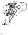
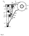
図1,2は、ウエブの提供に必要な材料ウエブ2を処理するための装置1の一部を図示している。材料ウエブ2は、装置1のローラ11上に保持されたリール21上に配置されている。装置1のフレーム13に対して堅固にかつ回転可能に取り付けられた複数の偏向ローラ12を介して、引き出された材料ウエブ2が処理セクションへと案内される。実際の処理装置、例えば、プリント又はエンボスステーションは、図示していない。
1 and 2 show part of an apparatus 1 for processing the
新しいリール21が挿入され、材料ウエブ2を引き出す際に材料ウエブが傾斜した状態で引き出されると、その結果として、互いに反対側となる一対の側面22,23に異なる張力が加わる。これによりウエブが引き裂かれることとなり、装置1を停止する必要性が生じる。
When a
上記の事象を防止するため、装置1はウエブガイド装置3を備えている。このガイド装置は、2つのフレームエレメント31,32を備えており、これらのフレームエレメントは、各々の端部領域311,321において第1のスピンドル33に回動可能に取り付けられている。スピンドル33の端部領域331は装置1のフレーム13に取り付けられているため、このスピンドル自体は回転しない。
In order to prevent the above event, the device 1 includes a
対向する端部領域312,322において、フレームエレメント31,32はウエブガイドローラ34を介して互いに連結されており、このウエブガイドローラ34に亘って材料ウエブ2が装置1の運転中に案内される。
In the
さらに、フレームエレメント31,32は、スピンドル33及びウエブガイドローラ34と平行をなす他のスピンドル35によって連結されている。スピンドル35及びウエブガイドローラ34の双方は、回転ボールベアリング36を介してフレームエレメント31,32に連結されている。したがって、スピンドル35及びウエブガイドローラ34は、各々の延長部を中心に回転するだけでなく、フレームエレメント31,32に対して傾斜可能である。
Further, the
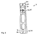
さらに、スピンドル35は、固定エレメント37を介してスピンドル33に連結されている。固定エレメント37は、2つの半部371,372からなり、これらの半部は、ねじ373,374により互いに固定されている。上記半部は、スピンドル33,35用のホルダ375,376をそれぞれ有している。スピンドル35は、固定エレメント37においてすべりブシュ38によって保持されており、このすべりブシュ38の内径は、スピンドル35の外径よりも、好ましくは5%〜20%、特に好ましくは10%〜12%大きい。
Further, the
ホルダ375,376のクリアランス及びねじ373,374の締付け力に応じて、どの程度堅固にスピンドル33,35に対して固定エレメント37を配置するかを決定することができる。
Depending on the clearance of the holders 375 and 376 and the tightening force of the
ねじ373,374を緩めた場合、固定エレメント37はスピンドル33,35上を移動可能な状態となる。図は固定エレメント37が側方を向いた状態を示している。固定エレメント37からフレームエレメント31,32までの各々の距離が実質的に均等であって、この距離の相違が、好ましくは20%を超えない程度、特に好ましくは10%を超えない程度となるように、装置1の運転中、固定エレメント37をスピンドル33,35上において中央に配置することが便宜である。これにより、所望とする材料ウエブ2に対するウエブガイドローラ34の対称的な配置が確実になる。
When the
材料ウエブ2が装置1に対して傾斜して挿入された場合、材料ウエブ2に加わる張力は非対称となる。したがって、張力及びウエブの速度は、材料ウエブ2の2つの側面22,23において異なる。
When the
材料ウエブ2がウエブガイドローラ34に沿ってガイドされるとただちに、ウエブガイドローラ34の互いに反対側となる側面に異なる力が加わる。ここでフレームエレメント及び第2のスピンドルは、上記の力を固定エレメント37に伝達するレバーとして機能する。したがって、固定エレメント37を中心としたトルクが生じる。
As soon as the
第1のスピンドル33は、端部領域331が堅固に取り付けられているため、スピンドル33自体は移動しない。しかし、図5,6から分かるように、フレームエレメント31,32は、スピンドル33を中心に回動可能であり、図4に示す双方のフレームエレメントが互いに釣り合っている位置に対して傾いている。スピンドル35及びウエブガイドローラ34は、上記の動きに追従することができ、かつ両者が回転ボールベアリング36を介して取り付けられているため、スピンドル33に対して所定の角度で、かつ本来のウエブガイド平面に対して所定の角度で傾斜することができる。
Since the
換言すると、ウエブガイドローラ34は、斜めに挿入された材料ウエブ3により生じる非対称の力に追従することができる。ウエブガイドローラ34は、当該ローラの端部領域に作用する力が再び均等になるまで(すなわち、トルクが固定エレメント37に伝達されなくなるまで)、傾いている。材料ウエブ2の進んでいる側の縁部に対してより迅速にブレーキがかかると、進んでいる側の縁部の加速がより穏やかになる。したがって、傾斜した材料ウエブ2の引き出しが修正され、材料ウエブ2は装置1において均等に進行する。この修正により、ウエブガイドローラ34は、再び図4に示すニュートラルポジションに戻り、材料ウエブ2がまっすぐに進行する間は上記位置に留まっている。
In other words, the
このように、本発明によれば、能動的な調節装置やセンサ等を必要とすることなく、傾斜した材料ウエブの引き出しを容易に修正することができる。本発明の装置は、特に、費用効果が高く、かつフェイルセーフの装置である。 As described above, according to the present invention, the withdrawal of the inclined material web can be easily corrected without requiring an active adjusting device or a sensor. The device of the present invention is particularly cost-effective and fail-safe.
1 装置
11 ローラ
12 偏向ローラ
13 フレーム
2 材料ウエブ
21 リール
22 側面
23 側面
3 ウエブガイド装置
31 フレームエレメント
311 端部領域
312 端部領域
32 フレームエレメント
321 端部領域
322 端部領域
33 第1のスピンドル
331 端部領域
34 ウエブガイドローラ
35 第2のスピンドル
36 回転ボールベアリング
37 固定エレメント
371 半部
372 半部
373 ねじ
374 ねじ
375 ホルダ
376 ホルダ
38 ブッシュ
1 device 11
Claims (16)
上記第1及び第2のフレームエレメントは、
各々の第1の端部領域(311,321)において第1のスピンドル(33)に回動可能に取り付けられており、
回転可能に取り付けられたウエブガイドローラ(34)を介して、各々の第2の端部領域(321,322)において互いに連結されており、
固定エレメント(37)を介して上記第1のスピンドル(33)に連結された第2のスピンドル(35)を介して互いに連結されている、ウエブガイド装置(3)。 A web guide device (3) for guiding a material web (2), in particular a film web, comprising first and second frame elements (31, 32),
The first and second frame elements are:
Each first end region (311, 321) is pivotally attached to a first spindle (33);
Connected to each other at each second end region (321, 322) via a web guide roller (34) mounted rotatably.
A web guide device (3) connected to each other via a second spindle (35) connected to the first spindle (33) via a fixing element (37).
Applications Claiming Priority (3)
| Application Number | Priority Date | Filing Date | Title |
|---|---|---|---|
| DE102014111312.8 | 2014-08-07 | ||
| DE102014111312.8A DE102014111312B3 (en) | 2014-08-07 | 2014-08-07 | Web guiding device and device for processing a material web |
| PCT/EP2015/066941 WO2016020206A1 (en) | 2014-08-07 | 2015-07-23 | Web guiding device and device for processing a web of material |
Publications (3)
| Publication Number | Publication Date |
|---|---|
| JP2017523104A true JP2017523104A (en) | 2017-08-17 |
| JP2017523104A5 JP2017523104A5 (en) | 2018-08-23 |
| JP6728537B2 JP6728537B2 (en) | 2020-07-22 |
Family
ID=53783685
Family Applications (1)
| Application Number | Title | Priority Date | Filing Date |
|---|---|---|---|
| JP2017506840A Expired - Fee Related JP6728537B2 (en) | 2014-08-07 | 2015-07-23 | Web guiding apparatus and apparatus for processing material webs |
Country Status (13)
| Country | Link |
|---|---|
| US (1) | US10294056B2 (en) |
| EP (1) | EP3177554B1 (en) |
| JP (1) | JP6728537B2 (en) |
| KR (1) | KR102442926B1 (en) |
| CN (1) | CN106660731B (en) |
| DE (1) | DE102014111312B3 (en) |
| DK (1) | DK3177554T3 (en) |
| ES (1) | ES2748681T3 (en) |
| HU (1) | HUE046162T2 (en) |
| MX (1) | MX2017001251A (en) |
| PL (1) | PL3177554T3 (en) |
| PT (1) | PT3177554T (en) |
| WO (1) | WO2016020206A1 (en) |
Families Citing this family (2)
| Publication number | Priority date | Publication date | Assignee | Title |
|---|---|---|---|---|
| CN112406285B (en) * | 2020-11-19 | 2022-07-26 | 浙江理工大学绍兴柯桥研究院有限公司 | Cloth stamp device for textile industry |
| KR102500196B1 (en) * | 2021-03-05 | 2023-02-17 | (주)삼현엔지니어링 | Apparatus for controlling tension of fabric |
Family Cites Families (12)
| Publication number | Priority date | Publication date | Assignee | Title |
|---|---|---|---|---|
| US2592090A (en) * | 1946-08-30 | 1952-04-08 | Hammond Bag & Paper Company | Paper winding and smoothing device |
| GB873431A (en) | 1957-12-12 | 1961-07-26 | Witton Ltd James | Improvements in web tensioning arrangements |
| NL140809B (en) * | 1965-04-10 | 1974-01-15 | Kalle Ag | DEVICE FOR MAINTAINING JOB TENSION IN A REPLACEMENT MATERIAL JOB. |
| DE1279032B (en) | 1966-09-17 | 1968-10-03 | Plamag Plauener Druckmaschinen | Device on rotary printing machines for supporting the bearing journals of a paper guide roller |
| DE2754180C2 (en) | 1977-12-06 | 1986-11-27 | M.A.N.- Roland Druckmaschinen AG, 6050 Offenbach | Device to compensate for different web tensions |
| US4527751A (en) * | 1983-09-22 | 1985-07-09 | Mobil Oil Corporation | Universal dancer speed control |
| US5911386A (en) * | 1997-08-14 | 1999-06-15 | Martin Automatic, Inc. | Ribbon guide method and apparatus |
| CN201176271Y (en) * | 2008-04-03 | 2009-01-07 | 沈阳新八达机电技术有限公司 | Small bright paper conveying device for cigarette-packaging machine |
| CN201347300Y (en) * | 2008-08-19 | 2009-11-18 | 上海宇泽机电设备有限公司 | Correction device |
| CN201427817Y (en) * | 2009-06-08 | 2010-03-24 | 东莞市奥力德自动化机械有限公司 | Automatic rectification tension device |
| CN201559342U (en) * | 2009-09-24 | 2010-08-25 | 陕西北人印刷机械有限责任公司 | Receiving press roller for winding printer |
| DE202013003546U1 (en) * | 2013-04-16 | 2013-06-07 | Von Ardenne Anlagentechnik Gmbh | Tape substrate chuck |
-
2014
- 2014-08-07 DE DE102014111312.8A patent/DE102014111312B3/en not_active Expired - Fee Related
-
2015
- 2015-07-23 MX MX2017001251A patent/MX2017001251A/en unknown
- 2015-07-23 KR KR1020177004212A patent/KR102442926B1/en active IP Right Grant
- 2015-07-23 WO PCT/EP2015/066941 patent/WO2016020206A1/en active Application Filing
- 2015-07-23 US US15/500,715 patent/US10294056B2/en active Active
- 2015-07-23 CN CN201580042338.6A patent/CN106660731B/en not_active Expired - Fee Related
- 2015-07-23 HU HUE15747405A patent/HUE046162T2/en unknown
- 2015-07-23 PL PL15747405T patent/PL3177554T3/en unknown
- 2015-07-23 EP EP15747405.7A patent/EP3177554B1/en active Active
- 2015-07-23 PT PT157474057T patent/PT3177554T/en unknown
- 2015-07-23 ES ES15747405T patent/ES2748681T3/en active Active
- 2015-07-23 DK DK15747405T patent/DK3177554T3/en active
- 2015-07-23 JP JP2017506840A patent/JP6728537B2/en not_active Expired - Fee Related
Also Published As
| Publication number | Publication date |
|---|---|
| DE102014111312B3 (en) | 2016-02-04 |
| MX2017001251A (en) | 2017-05-23 |
| HUE046162T2 (en) | 2020-02-28 |
| EP3177554A1 (en) | 2017-06-14 |
| US20170217711A1 (en) | 2017-08-03 |
| KR102442926B1 (en) | 2022-09-14 |
| KR20170039683A (en) | 2017-04-11 |
| EP3177554B1 (en) | 2019-08-14 |
| DK3177554T3 (en) | 2019-11-18 |
| US10294056B2 (en) | 2019-05-21 |
| PT3177554T (en) | 2019-11-19 |
| CN106660731B (en) | 2018-12-21 |
| CN106660731A (en) | 2017-05-10 |
| PL3177554T3 (en) | 2020-02-28 |
| WO2016020206A1 (en) | 2016-02-11 |
| ES2748681T3 (en) | 2020-03-17 |
| JP6728537B2 (en) | 2020-07-22 |
Similar Documents
| Publication | Publication Date | Title |
|---|---|---|
| KR20130018171A (en) | Winding machine and method for controlling thereof | |
| US8308037B2 (en) | Print media tensioning apparatus | |
| JP2017523104A (en) | Web guide apparatus and apparatus for processing material webs | |
| KR20090064276A (en) | Meandering modifying device of web | |
| TW201946079A (en) | Tension adjusting apparatus and winding apparatus | |
| CH706672A2 (en) | Cleaning device for removing cotton build-up from the lower front roller in a spinning machine | |
| JP4740639B2 (en) | Method for adjusting rollers in a printing press | |
| JP2007331867A (en) | Steering method for steel belt and steering device | |
| JPS5838543B2 (en) | Tension device for warp threads of loom | |
| KR102637289B1 (en) | winding machine | |
| JP2018035463A (en) | Device for bundling fiber bundles in spinning machine | |
| JP5905291B2 (en) | Web support equipment | |
| CA2627703C (en) | Core locking device | |
| JP2008037653A (en) | Roller for transferring and stretching tape material | |
| WO2019155839A1 (en) | Movement guiding device | |
| TWI637894B (en) | Tension adjustment system | |
| JP5819046B2 (en) | Meander correction device | |
| JP2017523104A5 (en) | ||
| JP3707465B2 (en) | Wire rewinding device | |
| US20170113474A1 (en) | Web processing apparatus | |
| JP2014051370A (en) | Thin film sheet take-up device and thin film sheet take-up method | |
| ITFI20000252A1 (en) | EXTENDING BAR FOR FLATENING TAPE MATERIALS SUCH AS FABRICS OR OTHERWISE, IN THE FORM OF A COMPOSITE ROLLER | |
| JP2018192652A (en) | Filament winding apparatus | |
| CN207876939U (en) | A kind of double deviation correcting devices of digital printer | |
| JP2010116261A (en) | Device for adjusting axial position of paper roll |
Legal Events
| Date | Code | Title | Description |
|---|---|---|---|
| A521 | Request for written amendment filed |
Free format text: JAPANESE INTERMEDIATE CODE: A523 Effective date: 20180709 |
|
| A621 | Written request for application examination |
Free format text: JAPANESE INTERMEDIATE CODE: A621 Effective date: 20180709 |
|
| A977 | Report on retrieval |
Free format text: JAPANESE INTERMEDIATE CODE: A971007 Effective date: 20190509 |
|
| A131 | Notification of reasons for refusal |
Free format text: JAPANESE INTERMEDIATE CODE: A131 Effective date: 20190528 |
|
| A521 | Request for written amendment filed |
Free format text: JAPANESE INTERMEDIATE CODE: A523 Effective date: 20190822 |
|
| A131 | Notification of reasons for refusal |
Free format text: JAPANESE INTERMEDIATE CODE: A131 Effective date: 20200121 |
|
| A521 | Request for written amendment filed |
Free format text: JAPANESE INTERMEDIATE CODE: A523 Effective date: 20200221 |
|
| TRDD | Decision of grant or rejection written | ||
| A01 | Written decision to grant a patent or to grant a registration (utility model) |
Free format text: JAPANESE INTERMEDIATE CODE: A01 Effective date: 20200602 |
|
| A61 | First payment of annual fees (during grant procedure) |
Free format text: JAPANESE INTERMEDIATE CODE: A61 Effective date: 20200608 |
|
| R150 | Certificate of patent or registration of utility model |
Ref document number: 6728537 Country of ref document: JP Free format text: JAPANESE INTERMEDIATE CODE: R150 |
|
| LAPS | Cancellation because of no payment of annual fees |