JP2017517199A - Device-to-device (D2D) communication - Google Patents
Device-to-device (D2D) communication Download PDFInfo
- Publication number
- JP2017517199A JP2017517199A JP2016566755A JP2016566755A JP2017517199A JP 2017517199 A JP2017517199 A JP 2017517199A JP 2016566755 A JP2016566755 A JP 2016566755A JP 2016566755 A JP2016566755 A JP 2016566755A JP 2017517199 A JP2017517199 A JP 2017517199A
- Authority
- JP
- Japan
- Prior art keywords
- enb
- rrc
- data
- radio bearer
- user equipment
- Prior art date
- Legal status (The legal status is an assumption and is not a legal conclusion. Google has not performed a legal analysis and makes no representation as to the accuracy of the status listed.)
- Granted
Links
- 238000004891 communication Methods 0.000 title claims abstract description 69
- 238000013468 resource allocation Methods 0.000 claims abstract description 100
- 238000000034 method Methods 0.000 claims abstract description 94
- 230000005540 biological transmission Effects 0.000 claims description 87
- 230000001413 cellular effect Effects 0.000 claims description 56
- 230000011664 signaling Effects 0.000 claims description 35
- 230000000737 periodic effect Effects 0.000 claims description 14
- 238000005516 engineering process Methods 0.000 claims description 9
- 230000004044 response Effects 0.000 claims description 8
- 230000000977 initiatory effect Effects 0.000 claims description 5
- 230000006870 function Effects 0.000 description 19
- 230000008569 process Effects 0.000 description 12
- 230000000694 effects Effects 0.000 description 10
- 238000001228 spectrum Methods 0.000 description 7
- 230000009471 action Effects 0.000 description 6
- 230000008901 benefit Effects 0.000 description 4
- 230000009286 beneficial effect Effects 0.000 description 3
- 230000010267 cellular communication Effects 0.000 description 3
- 239000000463 material Substances 0.000 description 3
- 238000005259 measurement Methods 0.000 description 3
- 238000013144 data compression Methods 0.000 description 2
- 230000007246 mechanism Effects 0.000 description 2
- 238000010295 mobile communication Methods 0.000 description 2
- 238000012545 processing Methods 0.000 description 2
- 230000004224 protection Effects 0.000 description 2
- 230000007704 transition Effects 0.000 description 2
- 238000013459 approach Methods 0.000 description 1
- 238000003491 array Methods 0.000 description 1
- 230000006399 behavior Effects 0.000 description 1
- 230000000739 chaotic effect Effects 0.000 description 1
- 239000003795 chemical substances by application Substances 0.000 description 1
- 238000001514 detection method Methods 0.000 description 1
- 238000010586 diagram Methods 0.000 description 1
- 238000011156 evaluation Methods 0.000 description 1
- 230000003993 interaction Effects 0.000 description 1
- 230000002452 interceptive effect Effects 0.000 description 1
- 239000004973 liquid crystal related substance Substances 0.000 description 1
- 230000007774 longterm Effects 0.000 description 1
- 238000007726 management method Methods 0.000 description 1
- 238000012986 modification Methods 0.000 description 1
- 230000004048 modification Effects 0.000 description 1
- 230000003287 optical effect Effects 0.000 description 1
- 239000004065 semiconductor Substances 0.000 description 1
- 230000008054 signal transmission Effects 0.000 description 1
- 239000007787 solid Substances 0.000 description 1
- 230000003068 static effect Effects 0.000 description 1
- 238000012546 transfer Methods 0.000 description 1
- 238000000411 transmission spectrum Methods 0.000 description 1
- 230000001960 triggered effect Effects 0.000 description 1
- 239000002699 waste material Substances 0.000 description 1
Images


Classifications
-
- H—ELECTRICITY
- H04—ELECTRIC COMMUNICATION TECHNIQUE
- H04W—WIRELESS COMMUNICATION NETWORKS
- H04W72/00—Local resource management
- H04W72/20—Control channels or signalling for resource management
- H04W72/25—Control channels or signalling for resource management between terminals via a wireless link, e.g. sidelink
-
- H—ELECTRICITY
- H04—ELECTRIC COMMUNICATION TECHNIQUE
- H04W—WIRELESS COMMUNICATION NETWORKS
- H04W76/00—Connection management
- H04W76/10—Connection setup
- H04W76/14—Direct-mode setup
-
- H—ELECTRICITY
- H04—ELECTRIC COMMUNICATION TECHNIQUE
- H04W—WIRELESS COMMUNICATION NETWORKS
- H04W28/00—Network traffic management; Network resource management
- H04W28/02—Traffic management, e.g. flow control or congestion control
- H04W28/0278—Traffic management, e.g. flow control or congestion control using buffer status reports
-
- H—ELECTRICITY
- H04—ELECTRIC COMMUNICATION TECHNIQUE
- H04W—WIRELESS COMMUNICATION NETWORKS
- H04W48/00—Access restriction; Network selection; Access point selection
- H04W48/02—Access restriction performed under specific conditions
-
- H—ELECTRICITY
- H04—ELECTRIC COMMUNICATION TECHNIQUE
- H04W—WIRELESS COMMUNICATION NETWORKS
- H04W48/00—Access restriction; Network selection; Access point selection
- H04W48/08—Access restriction or access information delivery, e.g. discovery data delivery
- H04W48/10—Access restriction or access information delivery, e.g. discovery data delivery using broadcasted information
-
- H—ELECTRICITY
- H04—ELECTRIC COMMUNICATION TECHNIQUE
- H04W—WIRELESS COMMUNICATION NETWORKS
- H04W48/00—Access restriction; Network selection; Access point selection
- H04W48/20—Selecting an access point
-
- H—ELECTRICITY
- H04—ELECTRIC COMMUNICATION TECHNIQUE
- H04W—WIRELESS COMMUNICATION NETWORKS
- H04W72/00—Local resource management
- H04W72/20—Control channels or signalling for resource management
- H04W72/23—Control channels or signalling for resource management in the downlink direction of a wireless link, i.e. towards a terminal
-
- H—ELECTRICITY
- H04—ELECTRIC COMMUNICATION TECHNIQUE
- H04W—WIRELESS COMMUNICATION NETWORKS
- H04W92/00—Interfaces specially adapted for wireless communication networks
- H04W92/16—Interfaces between hierarchically similar devices
- H04W92/18—Interfaces between hierarchically similar devices between terminal devices
-
- H—ELECTRICITY
- H04—ELECTRIC COMMUNICATION TECHNIQUE
- H04W—WIRELESS COMMUNICATION NETWORKS
- H04W72/00—Local resource management
- H04W72/20—Control channels or signalling for resource management
- H04W72/21—Control channels or signalling for resource management in the uplink direction of a wireless link, i.e. towards the network
-
- H—ELECTRICITY
- H04—ELECTRIC COMMUNICATION TECHNIQUE
- H04W—WIRELESS COMMUNICATION NETWORKS
- H04W76/00—Connection management
- H04W76/20—Manipulation of established connections
- H04W76/27—Transitions between radio resource control [RRC] states
Landscapes
- Engineering & Computer Science (AREA)
- Computer Networks & Wireless Communication (AREA)
- Signal Processing (AREA)
- Computer Security & Cryptography (AREA)
- Mobile Radio Communication Systems (AREA)
Abstract
デバイス間(D2D)通信を行うための技術が開示される。ユーザ機器(UE)は、UEから送信されるD2Dデータを識別することができる。D2Dデータは、UEが無線リソース制御(RRC)アイドルであるとき識別することができる。UEは、UEからD2Dデータを送信するために定義済リソース配分モードを使用することに限定され得る。サービス要求手順は、UEで開始することができる。サービス要求手順は、UEをRRCアイドルモードからRRC接続モードに切り替えるためにUEが進化型ノードB(eNB)とRRC接続確立手順を行うことをトリガすることができる。UEは、UEからD2Dデータを通信するためにeNBからアップリンク(UL)グラントを受信することができる。UEは、eNBによって提供されたULグラントを使用してD2Dデータを送ることができる。Techniques for performing device-to-device (D2D) communication are disclosed. User equipment (UE) can identify D2D data transmitted from the UE. D2D data can be identified when the UE is in radio resource control (RRC) idle. The UE may be limited to using a predefined resource allocation mode to transmit D2D data from the UE. The service request procedure can be initiated at the UE. The service request procedure can trigger the UE to perform an RRC connection establishment procedure with the evolved Node B (eNB) to switch the UE from RRC idle mode to RRC connected mode. The UE may receive an uplink (UL) grant from the eNB to communicate D2D data from the UE. The UE can send D2D data using the UL grant provided by the eNB.
Description
ワイヤレスモバイル通信技術は、さまざまな規格およびプロトコルを使用して、ノード(例えば、送信局)とワイヤレスデバイス(例えば、モバイルデバイス)との間でデータを送信する。いくつかのワイヤレスデバイスは、ダウンリンク(DL)送信に直交周波数分割多重接続(OFDMA)を、そしてアップリンク(UL)送信にシングルキャリア周波数分割多重接続(SC−FDMA)を使用して通信する。信号送信のために直交周波数分割多重化(OFDM)を使用する規格およびプロトコルは、第3世代パートナーシッププロジェクト(3GPP)ロング・ターム・エボリューション(LTE)、一般に業界団体にWiMAX(Worldwide interoperability for Microwave Access)として知られている、米国電気電子技術者協会(IEEE)802.16規格(例えば、802.16e、802.16m)、および、一般に業界団体にWiFiとして知られている、IEEE802.11規格を含む。 Wireless mobile communication technology transmits data between a node (eg, a transmitting station) and a wireless device (eg, a mobile device) using various standards and protocols. Some wireless devices communicate using orthogonal frequency division multiple access (OFDMA) for downlink (DL) transmission and single carrier frequency division multiple access (SC-FDMA) for uplink (UL) transmission. Standards and protocols that use Orthogonal Frequency Division Multiplexing (OFDM) for signal transmission are described in the Third Generation Partnership Project (3GPP) Long Term Evolution (LTE), generally to industry associations, WiMAX (Worldwide for Microwave Access). Includes the IEEE Institute of Electrical and Electronics Engineers (IEEE) 802.16 standard (eg, 802.16e, 802.16m), and the IEEE 802.11 standard, commonly known to industry associations as WiFi .
3GPP無線アクセスネットワーク(RAN)LTEシステムにおいて、ノードは、進化型ユニバーサル地上無線アクセスネットワーク(E−UTRAN)Node B(同じく一般に進化型Node B、拡張Node B、eNodeB、またはeNBと示される)と無線ネットワークコントローラ(RNC)との組合せとすることができ、ユーザ機器(UE)として知られるワイヤレスデバイスと通信する。ダウンリンク(DL)送信は、ノード(例えば、eNodeB)からワイヤレスデバイス(例えば、UE)への通信とすることができ、アップリンク(UL)送信は、ワイヤレスデバイスからノードへの通信とすることができる。 In the 3GPP Radio Access Network (RAN) LTE system, nodes are evolved universal terrestrial radio access network (E-UTRAN) Node B (also commonly referred to as evolved Node B, Enhanced Node B, eNodeB, or eNB) and radio. It can be in combination with a network controller (RNC) and communicates with a wireless device known as user equipment (UE). The downlink (DL) transmission can be communication from a node (eg, eNodeB) to a wireless device (eg, UE), and the uplink (UL) transmission can be communication from the wireless device to the node. it can.
同種ネットワークにおいて、同じくマクロノードと呼ばれるノードは、セル内のワイヤレスデバイスに基本的なワイヤレスカバレッジを提供することができる。セルは、ワイヤレスデバイスがマクロノードと通信するように動作可能な領域とすることができる。ヘテロジニアスネットワーク(HetNet)を使用して、ワイヤレスデバイスの使用法および機能の増加に起因するマクロノード上のトラフィック負荷の増加に対処することができる。HetNetは、マクロノードのカバレッジ領域(セル)の中で、それほど十分に計画されていないさらには完全に無秩序なやり方で配置され得る、より低い電力のノード(スモールeNB、マイクロeNB、ピコeNB、フェムトeNBまたはホームeNB[HeNB])のレイヤでオーバレイされる、計画された高電力マクロノード(またはマクロeNB)のレイヤを含むことができる。より低い電力のノード(LPN)は、一般に「低電力ノード」、スモールノード、またはスモールセルと呼ぶことができる。 In homogeneous networks, nodes, also called macro nodes, can provide basic wireless coverage for wireless devices in the cell. A cell may be an area in which a wireless device is operable to communicate with a macro node. A heterogeneous network (HetNet) can be used to address the increased traffic load on the macro node due to increased usage and functionality of wireless devices. HetNet is a lower power node (small eNB, micro eNB, pico eNB, femto, which can be deployed in a less well-planned and even completely chaotic manner within the coverage area (cell) of a macro node. It can include a layer of planned high power macro nodes (or macro eNBs) that is overlaid at the layer of the eNB or home eNB [HeNB]). A lower power node (LPN) may generally be referred to as a “low power node”, a small node, or a small cell.
LTEにおいて、データは物理ダウンリンク共有チャネル(PDSCH)を介してeNodeBからUEへ送信することができる。物理アップリンク制御チャネル(PUCCH)を使用して、データが受信されたことを知らせることができる。ダウンリンクおよびアップリンクのチャネルまたは送信は、時分割二重化(TDD)または周波数分割二重化(FDD)を使用することができる。 In LTE, data can be transmitted from the eNodeB to the UE via a physical downlink shared channel (PDSCH). A physical uplink control channel (PUCCH) may be used to indicate that data has been received. Downlink and uplink channels or transmissions can use time division duplex (TDD) or frequency division duplex (FDD).
本開示の特徴および利点は、本開示の特徴を、例として、ともに例示する、添付の図面と関連してなされる、以下の詳細な説明から明らかであろう。 The features and advantages of the present disclosure will become apparent from the following detailed description, taken in conjunction with the accompanying drawings, illustrating by way of example the features of the present disclosure.
次に、例示された例示的な実施形態を参照し、ここに特定の用語を使用してそれらの実施形態を説明する。しかし、それによって本発明の範囲の限定が意図されないことを理解されたい。 Reference will now be made to the exemplary embodiments illustrated, and specific language will be used herein to describe those embodiments. However, it should be understood that it is not intended to limit the scope of the invention.
本発明が開示され説明される前に、本発明が本明細書で開示される特定の構造、工程段階、または材料に限定されず、関連する技術分野の当業者によって認識されるようにそれらの均等物に拡張されることは理解されるはずである。本明細書で使われる用語が特定の実施例を説明する目的のためにのみ使用され、限定するように意図されないことは、同様に理解されるべきである。異なる図面の同じ参照符号は同じ要素を表す。フローチャートおよびプロセスに設けられる数は、ステップおよび動作を例示することにおいて明確にするために設けられるのであって、必ずしも特定の順序または並びを示唆するものではない。 Before the present invention is disclosed and described, it is not limited to the specific structures, process steps, or materials disclosed herein, as those skilled in the relevant art will recognize them. It should be understood that it extends to the equivalent. It should also be understood that the terminology used herein is used for the purpose of describing particular embodiments only and is not intended to be limiting. The same reference numbers in different drawings represent the same element. The numbers provided in the flowcharts and processes are provided for clarity in illustrating the steps and operations and do not necessarily imply a particular order or sequence.
技術実施形態の最初の概観が以下に提供され、それから特定の技術実施形態が後にさらに詳細に説明される。最初の概要は、読者がより早く技術を理解するのを支援するように意図されるが、技術の重要な特徴または本質的な特徴を識別するように意図されず、特許請求された主題の範囲を限定するようにもまた意図されない。 An initial overview of technical embodiments is provided below, and then specific technical embodiments are described in further detail later. The initial overview is intended to assist the reader in understanding the technology more quickly, but is not intended to identify key or essential features of the technology, It is also not intended to limit.
ユーザ機器(UE:User Equipment)でデバイス間(D2D:Device-to-Device、デバイス・ツー・デバイス)通信を行うことについて、技術が説明される。UEは、LTE/E−UTRAN関連の規格に従って動作することができ、または、UEは、E−UTRANに対して3GPP LTEリリース12(またはそれ以前)規格に従ってセルラ・モバイル・ネットワークで動作することができる。1つの実施例において、D2Dデータを送っているUEを送信側UEと呼ぶことができ、D2Dデータを受信しているUEを送信先UE、ターゲットUE、または受信側UEと呼ぶことができる。D2Dデータは、UE上で走っているD2Dアプリケーションによって生成することができる。UEは、D2DデータがUEのD2D無線ベアラを使用してターゲットUEに送信されるべきであることを識別することができる。1つの実施例において、D2Dデータは、送信側UEから単一のターゲットUEまたはターゲットUEのグループに送ることができる。D2Dアプリケーションは、UEが無線リソース制御(RRC:Radio Resource Control)アイドルモードであるときターゲットUEに送るべきD2Dデータを生成することができる。その上、UEのD2D無線ベアラは、UEがRRCアイドルモードであるとき存在し得るが、セルラ無線ベアラ(またはデータ無線ベアラ)は、UEがRRCアイドルモードであるとき確立することはできない。 The technology is described for performing inter-device (D2D: Device-to-Device) communication with user equipment (UE). The UE may operate according to LTE / E-UTRAN related standards, or the UE may operate in a cellular mobile network according to 3GPP LTE Release 12 (or earlier) standards for E-UTRAN. it can. In one embodiment, a UE sending D2D data can be referred to as a transmitting UE, and a UE receiving D2D data can be referred to as a destination UE, target UE, or receiving UE. D2D data can be generated by a D2D application running on the UE. The UE may identify that D2D data should be transmitted to the target UE using the UE's D2D radio bearer. In one embodiment, D2D data can be sent from a sending UE to a single target UE or a group of target UEs. The D2D application can generate D2D data to be sent to the target UE when the UE is in Radio Resource Control (RRC) idle mode. Moreover, the UE's D2D radio bearer may exist when the UE is in RRC idle mode, but the cellular radio bearer (or data radio bearer) cannot be established when the UE is in RRC idle mode.
UEがターゲットUEにD2Dデータを送るために、UEはRRC接続モードに移行することができる。UEは、ターゲットモードにD2Dデータを通信するために定義済リソース配分モードが使用されるべきであると決定することができる。UEは、eNBから報知されたシステム情報ブロック(SIB:System Information Block)に基づいて定義済リソース配分モードを決定することができる。1つの実施例において、定義済リソース配分モードはD2Dリソース配分モード1とすることができる。サービス要求手順は、UEの非アクセス層(NAS:Non-Access Stratum)で開始することができる。サービス要求手順は、UEのRRCレイヤがeNBとRRC接続確立手順を行うことをトリガすることができる。UEは、RRC接続確立手順の完了にあたり、RRCアイドルモードからRRC接続モードに切り替わることができる。UEは、今RRC接続モードであり、eNBにバッファ状態報告(BSR:Buffer Status Report)を送ることができ、それに応じて、UEは、ターゲットUEへのD2Dデータの送信のためにeNBからアップリンク(UL)グラントを受信することができる。UEは、eNBによって提供されたULグラントを使用してターゲットUEにD2Dデータを送ることができる。D2Dデータは、UEのD2D無線ベアラを使用してターゲットUEに送信され得る。
In order for the UE to send D2D data to the target UE, the UE may enter RRC connected mode. The UE may determine that the defined resource allocation mode should be used to communicate D2D data to the target mode. The UE can determine the defined resource allocation mode based on a system information block (SIB) broadcast from the eNB. In one embodiment, the defined resource allocation mode may be D2D
代替の構成において、D2Dデータは、UEがすでにRRC接続モードであるときUE上で走っているD2Dアプリケーションによって生成することができる。換言すれば、セルラ無線ベアラは、D2D無線ベアラと同様、UEのためにすでに確立することができる。UEは、ターゲットモードにD2Dデータを通信するために定義済リソース配分モード(例えば、D2Dリソース配分モード1)が使用されるべきであると決定することができる。UEは、UEのシグナリング無線ベアラを使用してeNBにRRC設定要求メッセージを送ることができ、それに応じて、UEは、eNBからRRC接続再設定メッセージを受信することができる。RRC接続再設定メッセージは、定義済リソース配分モードに対する1つまたは複数の設定パラメータを含み得る。これらの設定パラメータのいくつかの実施例は、周期的なD2D BSRタイマまたはD2D BSR再送信タイマを含み得る。UEは、1つまたは複数の設定パラメータを使用してeNBにバッファ状態報告(BSR)を送ることができる。それに応じて、UEはターゲットUEへのD2Dデータの送信のためにeNBからアップリンク(UL)グラントを受信することができる。UEは、eNBによって提供されたULグラントを使用してターゲットUEにD2Dデータを送ることができる。その上、UEは、UEのD2D無線ベアラを使用してD2Dデータを送ることができる。 In an alternative configuration, the D2D data can be generated by a D2D application running on the UE when the UE is already in RRC connected mode. In other words, a cellular radio bearer can already be established for the UE, similar to a D2D radio bearer. The UE may determine that a defined resource allocation mode (eg, D2D resource allocation mode 1) should be used to communicate D2D data to the target mode. The UE may send an RRC setup request message to the eNB using the UE's signaling radio bearer, and accordingly the UE may receive an RRC connection reconfiguration message from the eNB. The RRC connection reconfiguration message may include one or more configuration parameters for the defined resource allocation mode. Some examples of these configuration parameters may include a periodic D2D BSR timer or a D2D BSR retransmission timer. The UE may send a buffer status report (BSR) to the eNB using one or more configuration parameters. In response, the UE may receive an uplink (UL) grant from the eNB for transmission of D2D data to the target UE. The UE may send D2D data to the target UE using the UL grant provided by the eNB. Moreover, the UE can send D2D data using the UE's D2D radio bearer.
進化型ユニバーサル地上無線アクセスネットワーク(E−UTRAN)などの、3GPP LTEネットワークのためのデバイス間(D2D)通信は、3GPP LTEリリース12で規格化されている。D2D通信は、2つのユーザ機器(UE)などの、2つのデバイス間の直接通信である。2つのデバイス(例えば、LTEベースのデバイス)は、2つのデバイスがごく接近しているとき互いに直接通信することができるが、このようなD2D通信はセルラ・ネットワーク・インフラストラクチャを使用しない。D2D通信に対する1つの特定のアプリケーションは、公共安全サービスに関連している。さらに、D2D通信は、1つのUEから1つまたは複数のターゲットUEまたは受信側UEへの直接通信を可能にすることができ、したがってグループ通信を可能にすることができる。本明細書で説明される実施例は、ターゲットUEまたは受信側UEへの送信を意味することができるが、これはターゲットUEまたは受信側UEのグループへの送信とし得ることを理解すべきである。 Device-to-device (D2D) communication for 3GPP LTE networks, such as Evolved Universal Terrestrial Radio Access Network (E-UTRAN), is standardized in 3GPP LTE Release 12. D2D communication is direct communication between two devices, such as two user equipments (UEs). Two devices (eg, LTE-based devices) can communicate directly with each other when the two devices are in close proximity, but such D2D communication does not use a cellular network infrastructure. One particular application for D2D communication is related to public safety services. Furthermore, D2D communication can allow direct communication from one UE to one or more target UEs or receiving UEs, and thus can allow group communication. The embodiments described herein may mean transmission to a target UE or receiving UE, but it should be understood that this may be a transmission to a group of target UEs or receiving UEs. .
D2Dは、セルラスペクトルを使用している2つのUE間で直接リンクを可能にする。結果として、メディアまたは他のデータは、近距離で直接接続を使用して1つのデバイスから別のデバイスへ転送することができる。D2Dデータ通信を使用することによって、データをセルラネットワークに中継することなく直接通信することができ、それによって、ネットワークカバレッジの欠如もしくは貧弱さについての問題、またはネットワークに負荷をかけ過ぎることについての問題を回避することができる。セルラインフラストラクチャは、存在している場合、ピアディスカバリ、同期、ならびに識別情報およびセキュリティ情報の提供などの、他の問題点を支援することができる。 D2D allows a direct link between two UEs using cellular spectrum. As a result, media or other data can be transferred from one device to another using a direct connection at a short distance. By using D2D data communication, data can be communicated directly without relaying it to the cellular network, thereby causing problems with lack or poor network coverage or overloading the network. Can be avoided. The cellular infrastructure, when present, can assist with other issues such as peer discovery, synchronization, and provision of identification and security information.
D2D通信の使用は、ユーザにいくつかの利益を提供する。例えば、デバイスはセルラインフラストラクチャから離れていてもよい。D2D通信はネットワークインフラストラクチャに頼らないので、D2Dは、セルラネットワークが故障したとき(例えば、災害の間)でさえ、デバイスがローカルに通信することを可能にすることができる。認可されたスペクトルを使用することによって、D2D通信を行うために使用される周波数は、それほど干渉を受けない。その上、2つのデバイスがごく接近している場合、減少した送信電力レベルが使用され、それによってデバイスで電力を節約する。 The use of D2D communication offers several benefits to the user. For example, the device may be remote from the cellular infrastructure. Since D2D communication does not rely on the network infrastructure, D2D can allow devices to communicate locally even when the cellular network fails (eg, during a disaster). By using the licensed spectrum, the frequencies used to perform D2D communication are less subject to interference. Moreover, if the two devices are in close proximity, a reduced transmit power level is used, thereby saving power at the device.
D2D通信機能は、3GPP LTE規格でProSe(近接サービス)直接通信と呼ばれる。D2D通信は、主に公共安全使用事例を目標としているが、同様に他の用途に使用することができる。D2D機能は、セルラ無線スペクトルを介して、しかしデータはセルラ・ネットワーク・インフラストラクチャによって搬送されずに、UE間の直接通信を可能にする。D2D通信は、UEがセルラネットワークのカバレッジの外にあるとき、あるいは、UEがセルラネットワークのカバレッジの中にあるとき、起こり得る。UEのアクセス層の中で、D2DデータはD2D無線ベアラによって搬送され得る。 The D2D communication function is called ProSe (proximity service) direct communication in the 3GPP LTE standard. D2D communication is primarily targeted for public safety use cases, but can be used for other applications as well. The D2D function allows direct communication between UEs over the cellular radio spectrum but without the data being carried by the cellular network infrastructure. D2D communication can occur when the UE is outside the coverage of the cellular network or when the UE is within the coverage of the cellular network. Within the access layer of the UE, D2D data may be carried by the D2D radio bearer.
D2D無線ベアラはセルラ通信のために使用される無線ベアラと類似している一方、いくつかの重要な相違がある。例えば、D2D無線ベアラは、UEが無線リソース制御(RRC)アイドルモードまたはRRC接続モードのどちらかであるとき、UEに存在し得る。換言すれば、D2D無線ベアラは、UEがRRC_IDLEモードまたはRRC_CONNECTEDモードのどちらかであるとき存在し得る。これに対して、セルラ無線ベアラ(またはデータ無線ベアラ)は、UEがRRC接続モードであるときだけ存在し得る。その上、D2D無線ベアラは、UEのアプリケーションレイヤからのデータの到着に基づいて必要に応じて、UEによって作り出し、解放することができる。これに対して、セルラ無線ベアラは、ネットワークによって作り出され、設定され、解放される。 While D2D radio bearers are similar to radio bearers used for cellular communications, there are some important differences. For example, a D2D radio bearer may be present at the UE when the UE is in either radio resource control (RRC) idle mode or RRC connected mode. In other words, a D2D radio bearer may exist when the UE is in either RRC_IDLE mode or RRC_CONNECTED mode. In contrast, a cellular radio bearer (or data radio bearer) may only exist when the UE is in RRC connected mode. Moreover, D2D radio bearers can be created and released by the UE as needed based on the arrival of data from the UE's application layer. In contrast, cellular radio bearers are created, set up and released by the network.
UEがセルラネットワークのカバレッジの中にあるとき、D2D送信が通常のセルラ通信に干渉をもたらすことを回避するためにセル内の他のUE送信とUEからのD2D送信を調整することは有益であり得る。換言すれば、2つのデバイスがセルラネットワークのカバレッジの中でD2D通信を行おうと試みているとき、無線スペクトルに対するセルラアクティビティは、同じ無線スペクトルに対するD2Dアクティビティと調整することができる。UEが別のUEにD2Dデータを送信するとき、D2Dデータは、UEがネットワークに送信するために使用するのと同じ搬送周波数で送信される。その上、D2D送信およびD2D受信は、ネットワークのスペクトルのアップリンク部分で起こり得る。したがって、UEは、通常UEの送信スペクトルのアップリンクとなるもので、D2Dデータを送信または受信する。ネットワークはセル内のさまざまなUEのためにアップリンク送信をスケジューリングすることができるので、ネットワークは、これらのD2D送信がネットワークによってスケジューリングされたUEからのアップリンク送信と衝突または干渉しないことを保証しなければならない(セルラアクティビティとD2Dアクティビティは同じスペクトルで起こるため)。 When the UE is in the coverage of the cellular network, it is beneficial to coordinate the D2D transmission from the UE with other UE transmissions in the cell to avoid D2D transmissions from interfering with normal cellular communication obtain. In other words, when two devices are attempting D2D communication within the coverage of a cellular network, the cellular activity for the radio spectrum can be coordinated with the D2D activity for the same radio spectrum. When a UE transmits D2D data to another UE, the D2D data is transmitted on the same carrier frequency that the UE uses to transmit to the network. Moreover, D2D transmission and D2D reception can occur in the uplink part of the spectrum of the network. Therefore, the UE is usually an uplink of the transmission spectrum of the UE, and transmits or receives D2D data. Since the network can schedule uplink transmissions for various UEs in the cell, the network ensures that these D2D transmissions do not collide or interfere with uplink transmissions from UEs scheduled by the network. (Since cellular activity and D2D activity occur in the same spectrum).
1つの実施例において、送信UEがネットワークからのD2D送信のための送信リソースを要求する、D2Dリソース配分モード1を使用して、セルラアクティビティとD2Dアクティビティとの間の調整を達成することができる。UEは、UEが典型的なUEからネットワークへの送信のために送信リソースを要求するときと類似したやり方で、送信リソースを要求することができる。例えば、送信リソースに対する要求は、通常、UEが進化型ノードB(eNB)に媒体アクセス制御(MAC:Media Access Control)レイヤバッファ状態報告(BSR)を送ることによって起こることが可能であり、eNBは、物理レイヤ内でシグナリングされたアップリンク(UL)グラント上の形式で割り当てられたリソースで応答することができる。
In one embodiment, coordination between cellular activity and D2D activity can be achieved using D2D
D2Dリソース配分モード1において、eNBは、UEがD2D送信を行う、時間および周波数をスケジューリングすることに積極的に関与し得る。代替のシナリオにおいて、UEは、UEがD2D送信を行うことにおいてより自律的である、D2Dリソース配分モード2を使用してD2D送信を行うことができる。D2Dリソース配分モード2は、UEがeNBのカバレッジの外にあるとき起こり得るが、UEがカバレッジの中にあるとき同様に起こり得る。モード2において、eNBはそのリソースのある一定の部分を予約することができ、そして次に、UEがその予約された部分の中でD2Dデータをどこで送信するか自律的に選択することを可能にする。リソースはどちらかというと静的なやり方でD2D通信のために予約されているので、予約リソースのすべてが使用されていないときリソースの浪費が生じ得る。これに対して、D2Dリソース配分モード1は、D2D送信が差し迫っているときネットワークが動的にリソースを配分することを可能にし、それによってより効率的なソリューションを提供する。D2D送信を行うことを望むUEがない場合、リソースは不必要にD2D送信のために割り当てられることがなく、通常のセルラ通信のために利用可能である。
In D2D
1つの実施例において、D2Dリソース配分モード1は、UEがRRC_CONNECTEDにあるとき使用することができる。換言すれば、UEとeNBとの間に有効な接続がある。その上、UEはD2Dアクティビティの期間中、RRC_CONNECTEDに留まることになっている。eNBは、UEがD2D送信を行うことを可能にするようにUEにリソースを割り当てるためにこの接続を使用することができる。MACレイヤおよび物理層シグナリングの両方とも、割り当てられたセル無線ネットワーク一時的識別子(C−RNTI)を有するUEに依拠し得るので、UEはRRC_CONNECTEDにあるべきである。その上、RRC_CONNECTEDにあるUEは、eNBがUEのバッファ状態報告行動を制御するためにパラメータでUEを設定することを可能にする。しかしながら、非アクセス層(NAS)およびアクセス層(AS)レイヤの両方を伴う、UEをRRCアイドルモードからRRC接続モードへ移行させるための従前のプロセスは、D2Dシナリオに適していない。
In one embodiment, D2D
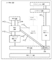
図1は、ユーザ機器(UE)140に対する無線リソース制御(RRC)接続を確立するための旧式の技術を例示する。UE140がネットワークに送るべきセルラデータを有するとき、UE140を無線リソース制御(RRC)アイドルモードからRRC接続モードへ移動させるために、多くのステップをUE140内のエンティティによって行うことができる。UE140は、RRC接続モードへ移行すると、データを進化型ノードB(eNB)に通信することができる。UE140内のエンティティは、アプリケーション120、インターネットプロトコル(IP)スタック122、無線アクセスベアラ(RAB)マネージャ124、非アクセス層(NAS)レイヤ126、RRCレイヤ128、シグナリング無線ベアラ130、セルラ無線ベアラ132および物理レイヤ134を含み得る。
FIG. 1 illustrates an older technique for establishing a radio resource control (RRC) connection to user equipment (UE) 140. When UE 140 has cellular data to send to the network, many steps can be performed by entities within UE 140 to move UE 140 from radio resource control (RRC) idle mode to RRC connected mode. When the UE 140 transitions to the RRC connection mode, the UE 140 can communicate data to the evolved Node B (eNB). Entities within UE 140 include application 120, Internet Protocol (IP) stack 122, radio access bearer (RAB) manager 124, non-access layer (NAS)
UE140は、最初はRRCアイドルモードとすることができる。UE140がRRCアイドルモードであるとき、セルラ無線ベアラ(またはデータ無線ベアラ)は存在せず、ユーザデータをUE140からネットワークに転送することはできない。 UE 140 may initially be in RRC idle mode. When UE 140 is in RRC idle mode, there is no cellular radio bearer (or data radio bearer) and user data cannot be transferred from UE 140 to the network.
ステップ102において、UE140のアプリケーション120は、送信のためのユーザデータを生成することができる。アプリケーション120は、送信のためにIPスタック122にデータを引き渡すことができ、データはそれからRABマネージャ124に引き渡される。
In
ステップ104において、RABマネージャ124は、適切な無線ベアラがUE140に存在するかどうかを追跡することができる。RABマネージャ124がUE140のために無線ベアラが確立されないことを検出するとき、RABマネージャ124は、無線ベアラの作成を求めてNASレイヤ126に要求を送ることができる。
In
ステップ106において、NASレイヤ126は、ネットワークに無線ベアラを確立するように要求するサービス要求手順を開始することができる。サービス要求手順を行うために、NAS126は、アクセス層の中のRRCレイヤ128にサービス要求メッセージを提供することができる。サービス要求メッセージは、UE140に対するRRC接続の確立を要求することができる。
In
ステップ108において、RRCレイヤ128は、eNBとRRC接続確立手順を行うことができ、それはシグナリング無線ベアラ130をもたらすことができる。シグナリング無線ベアラ130を使用して、ネットワークにNASサービス要求メッセージを送ることができる。
In
ステップ110において、NASサービス要求メッセージを受信することに応じて、ネットワークは、UE140のためにセルラ無線ベアラ132(またはデータ無線ベアラ)を確立するためにさまざまなアクションを開始することができる。例えば、ネットワークは、セルラ無線ベアラ132を確立するように、RRCシグナリングを介して、UE140に命令することができ、そして次に、RRC128はUE140でそれらのセルラ無線ベアラ132をセットアップすることができる。ユーザデータはその後、セルラ無線ベアラ132を使用してUEからネットワークへ送信することができる。したがって、無線ベアラがUE140のために確立されないとき、UE140は、それらの無線ベアラの作成のためにRRC接続モードに入ることになっている。その上、ネットワークは、UE140のためのセキュリティの確立などの、他のアクションを行うことができる。
In
UEに対するRRC接続を確立するための上述のプロセスは、D2D通信に直接適していない。セルラ無線ベアラと対照的に、例えば、UEはネットワークカバレッジから外れていた間にD2D無線ベアラを使用していたので、UEがアイドルモードであるときD2D無線ベアラはすでに存在し得る。したがって、送るデータがあるが確立された無線ベアラがないときはいつでもサービス要求を行うようにNASをトリガする、旧式システムにおけるRABマネージャ機能は、D2Dに適用するのが難しい。UEがD2Dリソース配分モード1を使用するべきであるかどうか、したがってRRC_CONNECTEDに移動されるべきであるかどうかについての判断は、サービス要求手順をトリガすることを決めるとき通常NASレイヤに利用可能でないであろうアクセス層特有の情報に依存し得る。
The above-described process for establishing an RRC connection to the UE is not directly suitable for D2D communication. In contrast to cellular radio bearers, for example, a D2D radio bearer may already exist when the UE is in idle mode because the UE was using a D2D radio bearer while out of network coverage. Therefore, the RAB manager function in older systems that triggers NAS to make service requests whenever there is data to send but no established radio bearer is difficult to apply to D2D. The decision as to whether the UE should use D2D
前のソリューションで、RABマネージャは、NASに無線ベアラを確立するように要求することができ、それは次に、NASにRRC接続の確立を要求させる。しかしながら、D2D無線ベアラがすでに存在し得るので、この前のソリューションは、D2D事例に直接適用可能でない。換言すれば、D2Dリソース配分モード1が使用されるべきであるとUEが決定するとき、D2D無線ベアラは、すでに使用中であり得る。D2D無線ベアラは、UEがRRCアイドルモードであるときでさえ、存在し得る。1つの実施例において、UEは、最初はネットワークカバレッジから外れていてD2D送信のためにD2Dリソース配分モード2を使用している場合があり、それによって、UEは、リソースの設定されたプールから送信リソースを自律的に選択する。UEはその後、D2Dリソース配分モード1が使用されることになっているセルのネットワークカバレッジに入ることができる。しかしながら、D2Dベアラは、UEがネットワークカバレッジから外れていたときに、前もって確立されていて、UEは、ネットワークカバレッジに入るにあたりD2Dベアラを再確立しなくてもよい。したがって、RABマネージャの以前の機能(例えば、到着するデータを観測すること、および、UEのために無線ベアラが存在しないとき、RRC接続を確立するために適切なプロトコルを開始すること)は、D2D無線ベアラがUEですでに現存するとき、直接適用されない。
In the previous solution, the RAB manager can request the NAS to establish a radio bearer, which in turn causes the NAS to request establishment of an RRC connection. However, this previous solution is not directly applicable to the D2D case because D2D radio bearers may already exist. In other words, when the UE determines that D2D
本明細書で説明される技術は、UEがD2D通信を行うことを可能にするためにUEに対するRRC接続を確立するためのものである。例えば、UEはターゲットUEとD2D通信を行うことができる。UEがRRCアイドルモードであるとき、D2D無線ベアラでの送信のためのD2Dデータは、上位レイヤから(例えば、UE上で走っているアプリケーションから)UEで受信することができる。UEは、D2Dリソース配分モード1が使用されるべきであるかどうか決定するために一定の条件をチェックすることができる。モード1が使用される必要がない場合、UEは、(UEがRRCアイドルモードであるときでさえ)D2D無線ベアラを介してターゲットUEにデータを送信することができる。他方、モード1がデータを通信するために使用されるべきである場合、UEアクセス層は、UE NASにUEをRRCアイドルモードからRRC接続モードに移動させるように要求することができる。UE NASは、UEをRRCアイドルモードからRRC接続モードに移動させるためにサービス要求手順を開始することができる。サービス要求手順に代わる構成において、UE NASは、トラッキングエリア更新要求で「アクティブ」フラグをセットして、トラッキングエリア更新手順を開始することができ、それはUEに対するRRC接続の確立を可能にすることができる。
The techniques described herein are for establishing an RRC connection to a UE to allow the UE to perform D2D communication. For example, the UE can perform D2D communication with the target UE. When the UE is in RRC idle mode, D2D data for transmission on the D2D radio bearer can be received at the UE from an upper layer (eg, from an application running on the UE). The UE can check certain conditions to determine if D2D
1つの実施例において、UEがD2D送信を行うためにRRC接続モードに移行するべきであるかどうかは、ネットワークで使用されているリソース配分のタイプに依存し得る。例えば、ネットワークがD2Dリソース配分モード1を使用しているとき、UEはRRC接続モードに入るべきである。他方、ネットワークがD2Dリソース配分モード2を使用しているとき、UEはRRC接続モードに入ることはできない。
In one embodiment, whether the UE should transition to RRC connected mode for D2D transmission may depend on the type of resource allocation used in the network. For example, when the network is using D2D
図2は、UE250がデバイス間(D2D)通信を行うことができるようにするためにユーザ機器(UE)250に対する無線リソース制御(RRC)接続を確立することを例示する。UE250が別のUE(例えば、ターゲットUEまたは受信側UE)に送るべきD2Dデータを有するとき、UE250を無線リソース制御(RRC)アイドルモードからRRC接続モードに移動させるために、多くのステップをUE250内のエンティティによって行うことができる。UE250がD2D送信を行うためにD2Dリソース配分モード1を使用するべきであるとき、UE250はRRC接続モードに移動することができる。RRC接続モードに入ると、UE250は、ターゲットUEにD2Dデータを送信するためにリソースを要求することができる。UE250内のエンティティは、アプリケーション220、インターネットプロトコル(IP)スタック222、非アクセス層(NAS)レイヤ226、RRCレイヤ228、シグナリング無線ベアラ230、物理レイヤ234、D2D無線ベアラ236、媒体アクセス制御(MAC)レイヤ238、およびD2D MACレイヤ240を含み得る。この実施例において、UE250は無線アクセスベアラ(RAB)マネージャを含むことができない。あるいは、UE250はRABマネージャを含むことができるが、RABマネージャはD2D送信を行うために使用されない。
FIG. 2 illustrates establishing a radio resource control (RRC) connection for user equipment (UE) 250 to enable UE 250 to perform device-to-device (D2D) communication. When UE 250 has D2D data to send to another UE (eg, target UE or receiving UE), many steps are performed in UE 250 to move UE 250 from radio resource control (RRC) idle mode to RRC connected mode. Can be done by entities. When the UE 250 should use D2D
UE250は、最初はRRCアイドルモードとすることができる。UE140がRRCアイドルモードであるとき、セルラ無線ベアラは存在せず、ユーザデータをUE140からネットワークに転送することはできない。しかしながら、D2D無線ベアラはUE250のために存在し得る。D2D無線ベアラは、D2Dデータを送受信するためにUE250によってすでに使用されている場合がある。 UE 250 may initially be in RRC idle mode. When UE 140 is in RRC idle mode, there is no cellular radio bearer and user data cannot be transferred from UE 140 to the network. However, a D2D radio bearer may exist for UE 250. The D2D radio bearer may already be used by the UE 250 to send and receive D2D data.
ステップ202において、UE250のアプリケーション220は、送信のためのユーザD2Dデータを生成することができる。アプリケーション220は、送信のためにIPスタック222にD2Dデータを引き渡すことができる。IPスタック222は、送信のためにD2D無線ベアラ236にD2Dデータを引き渡すことができ、D2D無線ベアラ236は、送信のために保留中のD2Dデータがあることを、MACレイヤ238、またはより具体的にはMACレイヤの中のD2D MAC240機能に通知することができる。
In
ステップ204において、UE240のMACレイヤ238は、D2Dデータが保留中の送信であることをRRCレイヤ228に示すことができる。1つの実施例において、MACレイヤ228は、無線にアクセスするためにすべての無線ベアラによって使用される単一エンティティである。D2D MAC240は、D2D通信に関連したMACレイヤ238の機能を表すことができる。代替の実施例において、UE250内の無線リンク制御(RLC)レイヤまたはパケットデータ圧縮プロトコル(PDCP)レイヤなどの、UE250内の他のレイヤは、保留中のD2Dデータ送信をRRCレイヤ228に示すことができる。
In
ステップ206において、D2Dユーザデータの送信の前に、UE250のRRCレイヤ228は、UE250がD2Dリソース配分モード1を使用するべきであるかどうか、またはUE250がリソース配分モード2を使用することができるかどうかをチェックすることができる。1つの実施例において、UE250は、ネットワークから前もって報知されたシステム情報ブロック(SIB)メッセージに基づいて、どちらのモードが使用されるべきか決定することができる。リソース配分モード1が使用されるべきであるとUE250が決定する場合、RRCレイヤ228は、NASレイヤ226にUE250をRRC接続モードに移動させるように要求することができる。換言すれば、リソース配分モード1が使用されるべきである場合、UE250は、D2Dデータ送信が起こるために、RRC接続モードに入るべきである。
In
ステップ208において、UE250のNASレイヤ226は、UE250のRRCレイヤ228から、UE250をRRC接続モードに移動させる要求を受信することができる。NASレイヤ226はサービス要求手順を開始することができる。サービス要求手順は、UE250のためのセルラ無線ベアラの確立をもたらすことができる。サービス要求手順を行うために、NASレイヤ226は、アクセス層の中のRRCレイヤ228にサービス要求メッセージを提供することができる。NASレイヤ226からのサービス要求メッセージは、RRCレイヤ228にUE250に対するRRC接続を確立するように要求することができる。代替の実施例において、サービス要求手順を行うよりむしろ、UEのNASレイヤ226は、トラッキングエリア更新要求でセットされた「アクティブ」フラグでトラッキングエリア更新手順を開始することができる。結果として、UE250のRRCレイヤ228に、UE250に対するRRC接続を確立するように通知することができる。
In
ステップ210において、UE250のRRCレイヤ228は、進化型ノードB(eNB)とRRC接続確立手順を行う。結果として、UE250に対してRRC接続を確立することができ、UE250のためのシグナリング無線ベアラ230を作り出すことができる。換言すれば、UE250は、RRC接続確立手順の完了にあたり、RRC接続モードであるように切り替わることができる。それから、シグナリング無線ベアラを使用して、ネットワークにNASサービス要求メッセージを送ることができる。
In
ステップ212において、UE250がRRC接続モードになった時点で、RRCレイヤ228は、UE250がRRC_CONNECTEDにあることをMACレイヤ238に示すことができる。RRCレイヤ228は、UE250がD2Dリソース配分モード1を使用してD2D送信を行うことを続行するべきであることを示すことができる。この指示は、D2Dリソース配分モード1に特有のさまざまな設定パラメータを含み得る。例えば、RRCレイヤ228からMACレイヤ238への指示は、周期的なD2D BSRタイマおよびD2D BSR再送信タイマを含み得る。1つの実施例において、RRCレイヤ228は、RRC接続の確立にあたりeNBからD2Dリソース配分モード1に特有のさまざまな設定パラメータを受信することができる。UE250は今、eNBにMACレイヤバッファ状態報告(BSR)を送るためにD2Dリソース配分モード1を使用することができる。換言すれば、MACレイヤ238は、さまざまな設定パラメータ(例えば、周期的なD2D BSRタイマ、D2D BSR再送信タイマ)を使用してeNBにBSRを送ることができる。eNBはアップリンク(UL)グラントで応答することができ、その後、UE250はそれらのULグラントを使用してD2Dデータを送信することができる。換言すれば、ULグラントは、UEのD2D送信が他の前もってスケジューリングされたセルラ送信(すなわち、UEからネットワークに送られるデータ)と同時に起こらないように、どの時間にどの周波数でUE250がD2D送信を行うべきであるかをUE250に知らせることができる。このプロセスは、D2D無線ベアラを使用して(すなわち、セルラ無線ベアラではなく)D2D送信を行うことを伴うことができ、実質的にさらなる相互作用がNASレイヤ226とRRCレイヤ228との間で起こる必要がない。UE250が送信すべきD2Dデータを有しRRC_CONNECTEDに留まる限りずっと、UE250はこのプロセスを使用し続けることができる。
In
ステップ214において、NASサービス要求メッセージを受信することに応じて、ネットワークは、セルラ無線ベアラを確立するためにさまざまなアクションを開始することができる。しかしながら、セルラ無線ベアラの確立は、D2Dベアラを使用して送られるD2Dデータに影響を与えない。実施例のアクションは、その後確立されるセルラ無線ベアラと同様、シグナリング無線ベアラ230を保護する、アクセス層セキュリティを確立することを含み得る。しかしながら、アクセス層セキュリティはD2D無線ベアラを保護するために使用されず、D2D無線ベアラは、UE250がRRC_IDLEにあるかまたはRRC_CONNECTEDにあるかどうかにかかわらず動作することができる別個のセキュリティ保護を有する。その上、ネットワークは、セルラ無線ベアラを確立するように、RRCシグナリングを介して、UE250に命令することができる。UE250のRRCレイヤ228は、その後、それらのセルラ無線ベアラをセットアップするために機能する。
In
いくつかの実施例において、UEがリソース配分モード1を使用することに制限を受けるかどうかの決定は、多くのやり方で行うことができる。例えば、UEが適当なセルに在圏する場合(すなわち、UEがネットワークカバレッジの中にあることを意味している)、リソース配分モード1が使用されるべきである。別の実施例において、信号レベルが設定された閾値を上まわる場合、リソース配分モード1が使用されるべきである。信号レベルは、参照シンボル受信電力(RSRP)測定値または参照シンボル受信品質(RSRQ)測定値に基づくことができる。さらに別の実施例において、D2D通信がサービス提供セルのカバレッジの中でサポートされるということをサービス提供セルがシステム情報の中で示すかどうかを決定することができる。この指示はD2Dに特有のシステム情報ブロック(SIB)の存在によって暗黙的に示すことができ、または、それはシステム情報を持った特定のD2D関連パラメータの存在によって暗黙的に示すことができる。例えば、この指示はD2Dリソースプール情報の存在によって暗黙的に示すことができる。その上、サービス提供セルからのシステム情報は、UEがそのサービス提供セルの中でリソース配分モード1を使用するように制限されることを明示的に示すことができる。システム情報は、eNBからUEに報知することができる。さらなる実施例において、サービス提供セルは、D2D UEがeNBと接続を確立する(すなわち、RRC接続モードに入る)べきであることを示すことができ、その上でUEは、UEがD2Dリソース配分モード1またはモード2を使用するべきであるかどうかをeNBからの専用シグナリングを介して知らされる。この手法では、UEよりむしろ、eNBが、UEがD2Dリソース配分モード1またはモード2を使用するべきであるかどうか決定することができる。
In some embodiments, the determination of whether a UE is restricted from using
前に論じたように、MACレイヤは、保留中のD2Dデータ送信をRRCレイヤに知らせることができる。RRCレイヤは、一定の条件(例えば、UEがリソース配分モード1を使用するべきであるかどうか)を評価することができ、これらの条件が満たされるかどうかに応じて、RRCレイヤは、NASレイヤにRRC接続モードに移動するように要求することができる。代替の構成において、これらの条件は、PDCPレイヤ、MACレイヤまたはUE内の来るべきレイヤもしくは機能の中などの、UE内の他の場所で評価することができる。その上、条件の評価は、UE内の異なるエンティティ間に分散することができる。 As previously discussed, the MAC layer can inform the RRC layer of pending D2D data transmissions. The RRC layer can evaluate certain conditions (eg, whether the UE should use resource allocation mode 1), and depending on whether these conditions are met, the RRC layer can Can be requested to move to RRC connection mode. In alternative configurations, these conditions can be evaluated elsewhere in the UE, such as in the PDCP layer, MAC layer, or upcoming layers or functions in the UE. Moreover, the condition evaluation can be distributed among different entities within the UE.
前に論じたように、UEは、リソース配分モード1が使用されるべきであると決定することができ、結果として、RRCレイヤは、NASレイヤにUEをRRC_CONNECTEDに移動させるように要求することができる。代替のシナリオにおいて、UEは、D2Dリソース配分モード2が使用されるべきであると決定することができる。この場合、RRCレイヤは、D2Dリソース配分モード2が使用されるべきであるという指示でMACレイヤに応答することができ、上述のプロセスの他のステップは関連しない。
As previously discussed, the UE may determine that
1つの構成において、UEは、D2Dリソース配分モード1またはモード2を使用することを決定せず、むしろ単にUEがRRC_CONNECTEDに入るべきであると決定する。この場合、eNBは、UEがD2Dリソース配分モード1またはモード2を使用するべきであるかどうか決めることができる。この判断は、RRC_CONNECTION_SETUPメッセージまたはRRC_CONNECTION_RECONFIGURATIONメッセージのどちらかでUEに知らせることができる。特に、UEがD2Dリソース配分モード1またはモード2を使用するべきであるかどうかについてのeNBの判断は、UEのMACレイヤに通信することができる。
In one configuration, the UE does not decide to use D2D
1つの構成において、RRCは、リソース配分モード1が使用されるべきであると、およびRRC接続がUEに対して確立されるべきであると決定しない。むしろ、RRCレイヤは、D2D通信を行うためにRRC接続が必要とされる場合があるという指示をNASレイヤに提供することができる。その上、RRCレイヤは、NASレイヤが、サービス要求手順を開始するかどうか、したがってRRC接続の確立を要求するかどうか決めることを可能にするために必要なパラメータをNASレイヤに提供することができる。換言すれば、NASレイヤは、RRCレイヤと対照的に、リソース配分モード1が使用されるべきであるかどうか決定することができる。
In one configuration, RRC does not determine that
1つの構成において、UEをRRC_IDLEモードからRRC_CONNECTEDモードに移動させる目的は、MACレイヤ、NASレイヤおよび/またはRRCレイヤの間のメッセージ交換に含めることができる。この目的(すなわち、D2D送信)は、RRC接続要求メッセージの中で(例えば、「D2D」または「D2D通信」などの新たな「確立要因」値として)、またはRRC接続セットアップ完了メッセージで(例えば、新たな「D2D送信要求」情報要素で)、eNBに同様に提供することができる。RRC接続要求メッセージおよびRRC接続セットアップ完了メッセージは、ともにRRC接続確立手順の一部とすることができる。このような表示を含むことの利点は、eNBが、UEがD2Dリソース配分モード1を使用するべきであると知ることができ、したがってeNBがリソース配分モード1と関連付けられた適用可能な設定パラメータを自動的に提供できるということである。1つの実施例において、eNBは、RR接続再設定メッセージで設定パラメータ(例えば、周期的なD2D BSRタイマ、D2D BSR再送信タイマ)を提供することができる。RRC接続要求メッセージで新たなD2D特有の確立要因を使用することの別の利点は、eNBが重い負荷の下にある場合に、eNBがD2D通信の目的のための接続確立を優先させる、またはその優先度を下げることができるということである。例えば、D2Dがネットワークの中で公共安全ユーザによって使用されている場合、eNBは、D2D目的のための接続確立を受け入れることを選択することができる。他方、D2Dがネットワークの中で非公共安全ユーザによってサービスとして使用されている場合、eNBは、D2D目的のための接続確立を拒絶することを選択することができる。
In one configuration, the purpose of moving the UE from RRC_IDLE mode to RRC_CONNECTED mode may be included in message exchanges between the MAC layer, NAS layer and / or RRC layer. This purpose (i.e. D2D transmission) can be in an RRC connection request message (e.g. as a new "establishment factor" value such as "D2D" or "D2D communication") or in an RRC connection setup complete message (e.g. A new “D2D transmission request” information element) can be provided to the eNB as well. Both the RRC connection request message and the RRC connection setup complete message can be part of the RRC connection establishment procedure. The advantage of including such an indication is that the eNB knows that the UE should use D2D
1つの実施例において、セルラ無線ベアラ(またはデータ無線ベアラ)の確立は、D2Dユーザデータを送信する目的のために必須ではない。換言すれば、D2D送信は、eNBからアップリンクグラントを受信すると、成功裏に行うことができ、アップリンクグラントは、UEがD2D送信を行うことを許される一定の時間を示す。しかしながら、旧式のサービス要求手順は、たとえ送信されるのを待っているセルラデータがなくても、セルラ無線ベアラが確立されるという結果をもたらす。 In one embodiment, the establishment of a cellular radio bearer (or data radio bearer) is not essential for the purpose of transmitting D2D user data. In other words, the D2D transmission can be performed successfully upon receiving the uplink grant from the eNB, and the uplink grant indicates a certain time that the UE is allowed to perform the D2D transmission. However, the old service request procedure results in a cellular radio bearer being established even if there is no cellular data waiting to be transmitted.
1つの構成において、NASレイヤは、サービス要求手順の代わりにトラッキングエリア更新手順を(「アクティブ」フラグをセットせずに)開始することができる。トラッキングエリア更新手順は、セルラ無線ベアラが確立されることなくUEがRRC_CONNECTEDに移動されるという結果をもたらすことができる。セルラ無線ベアラはD2Dユーザデータを送信する目的のために必須ではなく、したがって必須ではない動作を回避することができるので、この構成は有利となり得る。しかしながら、アクセス層セキュリティが始められないことになり、結果として、シグナリング無線ベアラ上のRRCシグナリングはセキュリティ保護を持たないことになるので、この構成は同様に不利となり得る。その上、3GPP LTE仕様書の旧バージョンは、セルラ・ユーザ・プレーンが確立された後ハンドオーバを許可するだけであるから、別のeNBへのRRC接続のハンドオーバは、可能ではないことになる。別の実施態様は、モビリティ管理エンティティ(MME)が通常(アクティブフラグなしの)トラッキングエリア更新手順のすぐ後にRRC接続の解放を開始することであり、それは、セルラ無線ベアラが確立されそして次にeNBが(通常UEアクティビティの欠如に基づいて)RRC接続が解放されるべきであるときを決める状況と対照的である。 In one configuration, the NAS layer may initiate a tracking area update procedure (without setting the “active” flag) instead of a service request procedure. The tracking area update procedure can result in the UE being moved to RRC_CONNECTED without establishing a cellular radio bearer. This configuration may be advantageous because cellular radio bearers are not essential for the purpose of transmitting D2D user data, and thus can avoid non-essential operations. However, this configuration can be similarly disadvantageous since access layer security will not be initiated and as a result, RRC signaling on the signaling radio bearer will not have security protection. Moreover, since the previous version of the 3GPP LTE specification only allows handover after the cellular user plane is established, handover of the RRC connection to another eNB will not be possible. Another embodiment is that the mobility management entity (MME) initiates the release of the RRC connection immediately after the normal (no active flag) tracking area update procedure, which means that the cellular radio bearer is established and then eNB In contrast to the situation that determines when an RRC connection should be released (usually based on lack of UE activity).
1つの構成において、セルラ無線ベアラをUEのために確立することができ、そして次に、UEは、さまざまな設定パラメータ(例えば、周期的なD2D BSRタイマ終了、D2D BSR再送信タイマ)を使用してバッファ状態報告(BSR)を送ることができる。換言すれば、セルラ無線ベアラは、UEがeNBからアップリンクグラントを受信する前に確立され得る。セルラ無線ベアラがD2D送信の前に確立されることになっている場合、eNBがD2Dリソース配分モード1に関連した設定パラメータを含むRRCシグナリングを送る前にアクセス層セキュリティが確立され得るので、この構成は有利となり得る。eNBがRRCシグナリングを送る前のアクセス層セキュリティの確立は、ネットワークオペレータの選好とすることができる。
In one configuration, a cellular radio bearer can be established for the UE, and then the UE uses various configuration parameters (eg, periodic D2D BSR timer expiration, D2D BSR retransmission timer). Can send a buffer status report (BSR). In other words, the cellular radio bearer may be established before the UE receives an uplink grant from the eNB. If the cellular radio bearer is to be established prior to D2D transmission, this configuration can be used because access layer security can be established before the eNB sends RRC signaling including configuration parameters related to D2D
図3は、UE350が進化型ノードB(eNB)と無線リソース制御(RRC)接続モードにあるときデバイス間(D2D)通信を行うようにユーザ機器(UE)350を設定することを例示する。UE350が別のUE(例えば、ターゲットUEまたは受信側UE)に送るべきD2Dデータを有するとき、D2D送信を行うために多くのステップをUE350内のエンティティによって行うことができる。UE350がターゲットUEに送るべきD2Dデータを有するとき、UE350はすでにRRC_CONNECTEDにあり得る。しかしながら、UE350は、D2Dリソース配分モード1(またはモード2)に対するパラメータで設定されない場合があり、ここでUE350は、D2D送信を行うためにこれらのパラメータを使用するべきである。UE350内のエンティティは、アプリケーション320、インターネットプロトコル(IP)スタック322、非アクセス層(NAS)レイヤ326、RRCレイヤ328、シグナリング無線ベアラ330、物理レイヤ334、D2D無線ベアラ336、媒体アクセス制御(MAC)レイヤ338、およびD2D MACレイヤ340を含み得る。
FIG. 3 illustrates configuring user equipment (UE) 350 to perform inter-device (D2D) communication when UE 350 is in radio resource control (RRC) connection mode with evolved Node B (eNB). When UE 350 has D2D data to send to another UE (eg, target UE or receiving UE), many steps can be performed by an entity in UE 350 to perform D2D transmission. UE 350 may already be in RRC_CONNECTED when UE 350 has D2D data to send to the target UE. However, UE 350 may not be configured with parameters for D2D resource allocation mode 1 (or mode 2), where UE 350 should use these parameters to make D2D transmissions. Entities within UE 350 include: application 320, Internet Protocol (IP) stack 322, non-access layer (NAS)
UE350は、最初はRRC接続モードとすることができる。UE350がRRC接続モードであるとき、セルラ無線ベアラはすでにUE350のために存在し得る。UE350は、D2D送信を行うためではなく、むしろ、ネットワーク送信を、すなわち進化型ノードB(eNB)と、行うために、もともとRRC接続モードに入っている場合がある。UE350がRRC接続モードに入った後、UE350は、別のUEに送るD2Dデータを生成することができる。その上、D2D無線ベアラ336はUE350のために存在し得る。D2D無線ベアラ336は、現在のRRC接続の間にではなく、ある前の時点にD2Dデータの送受信のためにUE350によってすでに使用されている場合がある。D2D無線ベアラ336が現在のRRC接続の間にすでに使用されていた場合、UE350は、D2Dリソース配分モード1(またはモード2)用にすでに設定されていることがある。 UE 350 may initially be in RRC connected mode. When UE 350 is in RRC connected mode, a cellular radio bearer may already exist for UE 350. UE 350 may be originally in RRC connected mode to perform network transmission, ie, evolved Node B (eNB), rather than to perform D2D transmission. After UE 350 enters RRC connected mode, UE 350 can generate D2D data to send to another UE. Moreover, a D2D radio bearer 336 can exist for the UE 350. The D2D radio bearer 336 may already be used by the UE 350 for sending and receiving D2D data at some previous time, rather than during the current RRC connection. If the D2D radio bearer 336 has already been used during the current RRC connection, the UE 350 may already be configured for D2D resource allocation mode 1 (or mode 2).
ステップ302において、UE350のアプリケーション320は、送信のためのユーザD2Dデータを生成することができる。アプリケーション320は、送信のためにIPスタック322にD2Dデータを引き渡すことができる。IPスタック322は、送信のためにD2D無線ベアラ336にD2Dデータを引き渡すことができ、D2D無線ベアラ336は、送信のために保留中のD2Dデータがあることを、MACレイヤ338、またはより具体的にはMACレイヤの中のD2D MAC340機能に通知することができる。
In
ステップ304において、UE350のMACレイヤ338は、D2Dデータが保留中の送信であることをRRCレイヤ328に示すことができる。1つの実施例において、MACレイヤ328は、無線にアクセスするためにすべての無線ベアラによって使用される単一エンティティである。D2D MAC340は、D2D通信に関連したMACレイヤ338の機能を表すことができる。代替の実施例において、UE350内の無線リンク制御(RLC)レイヤまたはパケットデータ圧縮プロトコル(PDCP)レイヤなどの、UE350内の他のレイヤは、保留中のD2Dデータ送信をRRCレイヤ328に示すことができる。
In
ステップ306において、UE350は、D2Dリソース配分モード1が使用されるべきであるかどうか、またはUE350がリソース配分モード2を使用することができるかどうか決定することができる。UE350は、D2DデータがターゲットUEに送信される前に適切なリソース配分モードを決定することができる。リソース配分モード1が使用されるべきであるとUE350が決定する場合、UE350は、ネットワークにRRC要求を送ることができる。例えば、UE350のRRCレイヤ328は、eNBにRRC要求を送ることができる。要求メッセージは、D2Dリソース要求またはD2D設定要求などの、新たなメッセージであってもよい。D2Dリソース要求表示情報要素(IE:Information Element)またはD2D設定要求表示IEを新たな要求メッセージに含むことができる。あるいは、要求メッセージは、新たなD2Dリソース要求表示情報要素(IE)またはD2D設定要求表示IEを包含するUE ASSISTANCE INFORMATIONなどの、既存のメッセージとすることができる。要求メッセージは、(UE350がRRC接続モードであるから、すでに確立されている)シグナリング無線ベアラを使用してRRCレイヤ328からeNBに送ることができる。
In
代替の構成において、UE350は、D2Dリソース配分モード1またはモード2を使用するべきかどうか決定せず、むしろネットワークにRRC要求を送ることを決定する。結果として、eNBは、UE350がD2Dリソース配分モード1またはモード2を使用するべきであるかどうか決めることができる。eNBは、eNBからRRCレイヤ328へのシグナリングを介してこの判断をUE350に知らせることができる。もしeNBがRRCレイヤ328にUE350がD2Dリソース配分モード2を使用するべきであると知らせるならば、RRCレイヤ328は、D2D送信を行うときモード2を使用するようにMACレイヤ338に知らせることができる。
In an alternative configuration, the UE 350 does not decide whether to use D2D
ステップ308において、eNBは、UE350のRRCレイヤ328からのRRC要求に応答することができる。eNBは、D2Dリソース配分モード1のために必要な設定パラメータをUE350に提供することができる。これらの設定パラメータの実施例は、周期的なD2D BSRタイマおよびD2D BSR再送信タイマを含み得る。1つの実施例において、eNBは、RRC接続再設定メッセージの中の設定パラメータで応答することができる。UE350がD2D送信を行うためにD2Dリソース配分モード2を使用するべきである場合、RRC接続再設定メッセージは、D2Dリソース配分モード2を使用するようにとのUE350への命令を含み得る。
In
ステップ310において、RRCレイヤ328は、UE350がRRC_CONNECTEDにあること、およびUE350がD2Dリソース配分モード1を使用してD2D送信を行うことを続行するべきであることを、MACレイヤ338に示すことができる。その上、RRCレイヤ328は、D2D送信を行うためにD2Dリソース配分モード1を使用するために必要な設定パラメータをMACレイヤ338に提供することができる。UE350は、eNBにMACレイヤバッファ状態報告(BSR)を送るために設定パラメータを使用することができる。換言すれば、MACレイヤ338は、さまざまな設定パラメータ(例えば、周期的なD2D BSRタイマ、D2D BSR再送信タイマ)を使用してeNBにBSRを送ることができる。eNBはアップリンク(UL)グラントで応答することができ、その後、UE350はそれらのULグラントを使用してD2Dデータを送信することができる。換言すれば、ULグラントは、UEのD2D送信が他の前もってスケジューリングされたセルラ送信(すなわち、UEからネットワークに送られるデータ)と同時に起こらないように、どの時間にどの周波数でUE350がD2D送信を行うべきであるかをUE350に知らせることができる。
In
図4は、デバイス間(D2D)通信を行うようにUE410を設定するためのユーザ機器(UE)410と進化型ノードB(eNB)420との間の例示的なシグナリングを例示する。UE410は、eNB420にD2D設定要求メッセージを送ることができる。1つの実施例において、D2D設定メッセージは、UEのシグナリング無線ベアラを使用してeNB420に送ることができる。D2D設定メッセージは、D2D設定要求表示情報要素(IE)を含み得る。eNB420は、UE410にRRC接続再設定メッセージで応答することができる。RRC接続再設定メッセージは、周期的なD2D BSRタイマおよびD2D BSR再送信タイマなどの、さまざまなD2Dリソース配分モード1パラメータを含み得る。換言すれば、これらの再設定パラメータは、UE410がD2D送信を送るためにD2Dリソース配分モード1を使用することを可能にする。UE410は、RRC接続再設定メッセージを受信することに応じて、eNB420にRRC接続再設定完了メッセージを送ることができる。
FIG. 4 illustrates exemplary signaling between a user equipment (UE) 410 and an evolved Node B (eNB) 420 for configuring the
1つの実施例において、UE410およびeNB420は、UE410がもともと(RRC接続モードであるのと反対に)RRCアイドルモードであるとき上述と類似の無線インタフェースメッセージ交換を行うことができる。UE410がRRCアイドルモードであるとき、UE410は、上述のように、すなわちUEのD2D通信を行う要望をeNBに通知するためにUEがRRC接続要求メッセージの中の新たな「確立要因」値またはRRC接続セットアップ完了メッセージの中の新たな表示を使用することができるやり方のように、eNB420にD2Dデータ通信を行う要望を示さない。むしろ、UE410がRRC_CONNECTEDに成功裏に入った時点で、UE410は、eNB420にRRC要求メッセージ(例えば、D2D CONFIGURATION REQUEST)を送ることによって、UE410がD2D通信を行うことを望んでいるということをeNB420に知らせることができる。この時点で、UE410はeNB420にD2D設定要求メッセージを送ることができ、eNB420はUE410にRRC接続再設定メッセージを送ることができ、UE410はeNB420にRRC接続再設定完了メッセージを送ることができる。
In one embodiment,
図5は、システム情報ブロック2(SIB2)メッセージに含まれ得るデバイス間(D2D)通信のためのアクセスクラス禁止(ACB)パラメータの抽象構文記法(ASN)コード例を例示する。3GPP LTE規格の前バージョンでは、ネットワークは、アクセスクラス禁止(ACB)を使用することによってRRC接続セットアップ要求試行を制限することができる。D2Dの一部として、UEがD2Dリソース配分の目的のためにRRC接続要求を送ることをeNBが禁じることができるように、この機構を拡張することは有益であり得る。図5に示されるように、D2Dに特有のACBパラメータをシステム情報ブロック2(SIB2)に加えることができる。例えば、ac−BarringForD2D−r12は、ACB設定をセットアップするためにSIB2に加えることができる。 FIG. 5 illustrates an example abstract syntax notation (ASN) code for access class prohibition (ACB) parameters for device-to-device (D2D) communication that may be included in a System Information Block 2 (SIB2) message. In previous versions of the 3GPP LTE standard, the network may limit RRC connection setup request attempts by using access class prohibition (ACB). As part of D2D, it may be beneficial to extend this mechanism so that the eNB can prohibit the UE from sending RRC connection requests for the purpose of D2D resource allocation. As shown in FIG. 5, D2D-specific ACB parameters can be added to the system information block 2 (SIB2). For example, ac-BarringForD2D-r12 can be added to SIB2 to set up ACB settings.
アクセスクラス禁止で、ネットワークは、UEがD2Dの目的のためにネットワークにアクセスしているかどうか、またはUEが通常のトラフィック目的(例えば、音声通話、データ転送)のためにネットワークにアクセスしているかどうかに応じて、異なる禁止設定をセットしたい場合がある。ネットワークが過負荷になっていて、D2Dが公共安全ユーザによって使用されている場合、D2Dは優先され得るが、非D2Dトラフィックにアクセス禁止が適用され得る。D2Dが他の目的(例えば、写真共有、ビデオ共有)のために使用されている場合、UEからネットワークへのトラフィックは、デバイス間トラフィックの代わりに優先され得る。 With access class prohibited, the network is whether the UE is accessing the network for D2D purposes or whether the UE is accessing the network for normal traffic purposes (eg, voice calls, data transfer) Depending on the, you may want to set different prohibition settings. If the network is overloaded and D2D is being used by public safety users, D2D may be prioritized, but access prohibition may be applied to non-D2D traffic. If D2D is used for other purposes (eg, photo sharing, video sharing), traffic from the UE to the network may be prioritized instead of inter-device traffic.
UEがSIB2の中のACB設定を受信し、セルへのアクセスが特定のRRC接続確立試行に対して禁じられていると評価した場合、UEのRRCレイヤは、UEに適用されているD2Dリソース配分に対するアクセス禁止に起因してRRC接続を確立できなかったことについてUEの上位レイヤに知らせる。特に、RRCレイヤは、SIB2からのac−BarringForD2Dパラメータを上位レイヤに知らせることができ、その上でRRC確立手順が終了する。1つの実施例において、禁止に起因してRRC接続確立手順を成功裏に完了することができない場合、UEはリソース配分モード2を使用することができる。別の実施例において、リソース配分モード1に対するサポートは、システム情報ブロック(SIB)を介して使用禁止とすることができる。この実施例において、(モード1が使用禁止であるように)SIBを変更することは、進行中のD2D送信に影響を与えない。すなわち、RRC接続モードでリソース配分モード1をすでに使用しているUEは、eNBが、リソース配分モード2を使用するようにUEを設定するかまたはRRC接続を解放するまで、リソース配分のためにD2D BSRを送り続けることができる。
If the UE receives the ACB configuration in SIB2 and evaluates that access to the cell is prohibited for a particular RRC connection establishment attempt, the UE's RRC layer shall determine the D2D resource allocation applied to the UE The UE upper layer is informed that the RRC connection could not be established due to the access prohibition to the UE. In particular, the RRC layer can inform the upper layer of the ac-BarringForD2D parameter from the SIB2, and then the RRC establishment procedure ends. In one embodiment, the UE may use resource allocation mode 2 if the RRC connection establishment procedure cannot be completed successfully due to prohibition. In another embodiment, support for
1つの構成において、RRC接続は、無活動に起因して解放することができる。前のLTEシステムでは、eNBは、別名「無活動時間」として知られている、ある一定の期間、セルラ無線ベアラ(および時々シグナリング無線ベアラ)上で無活動を観測したとき、RRC接続の解放をトリガすることができる。リソース配分モード1を使用するD2D通信で、UEは、UEが送信リソースを要求し続けることを可能にするために、D2D通信が進行中である限りずっとRRC_CONNECTEDに留まることになっている。eNBは、UEの中にだけ存在するD2D無線ベアラ上のアクティビティの可視性を持たず、したがって、セルラ無線ベアラ上で無活動を観測するeNBは、UEがそのD2D通信を完了する前に、誤ってUEのRRC接続を解放することに決める場合がある。この問題は、eNBがD2D BSRの受信などのD2D関連MACアクティビティを観測することによって対処することができる。したがって、特定のUEに対するRRC接続は、eNBがセルラ無線ベアラ(および時々シグナリング無線ベアラ)上で無活動を観測し、ある一定の期間D2D BSR受信がないとき、解放することができる。UE無活動検出のためのこの追加の条件は、D2Dリソース配分モード1を使用するようにeNBが設定したUEに適用することができる。
In one configuration, the RRC connection can be released due to inactivity. In previous LTE systems, when an eNB observes inactivity on a cellular radio bearer (and sometimes a signaling radio bearer) for a period of time, also known as “inactivity time”, it releases the RRC connection. Can be triggered. In D2D communication using
したがって、RRC接続は、UEの無活動に起因して解放されず、むしろ、その特定のUEに関するeNBにおける無活動に起因して解放される。前のシステムでは、UEにおける無活動の定義済期間の後、eNBがRRC接続を解放することができるが、D2Dについては、eNBがD2D通信を実際に観測することができないので、状況が異なる。D2DデータはUEとターゲットUEとの間で直接転送されるので、eNBは、D2D送信が起こるときを正確に知らない。しかしながら、UEがリソース配分モード1を使用する場合、eNBは、UEがバッファ状態報告(BSR)を送るときを検出することができる。UEは、D2D送信を行うためのリソースを要求するために、BSRを送ることができる。したがって、eNBは、UEがD2D送信を積極的に送っているかどうか(BSRを通して)間接的に決定することができる。eNBがある一定の期間UEからのBSRを検出しない場合、eNBは、(D2D送信に関して)UEが無活動であると推測することができ、eNBは、UEとのRRC接続を解放することができる。
Thus, the RRC connection is not released due to UE inactivity, but rather is released due to inactivity at the eNB for that particular UE. In the previous system, the eNB can release the RRC connection after a defined period of inactivity at the UE, but for D2D, the situation is different because the eNB cannot actually observe D2D communication. Since D2D data is transferred directly between the UE and the target UE, the eNB does not know exactly when D2D transmission occurs. However, if the UE uses
D2D発見は、UEがごく接近している他のUEに気づくプロセスである。D2D発見プロセスは、発見信号およびメッセージの送信を伴うことができる。D2D発見プロセスは、UEがネットワークのカバレッジの中にあるとき適用可能とすることができる。D2D通信リソース配分モード1に類似して、D2D発見は、送信リソースを要求するためにUEがRRC_CONNECTEDにあることになっている、リソース配分タイプ2を有する。したがって、D2D通信に対する上述のものと類似の機構がD2D発見のプロセスに適用され得る。しかしながら、D2D発見との相違は、D2D発見プロトコル(同じくProSe発見プロトコルまたはProSeプロトコルと呼ばれる)がアクセス層の外に存在し、NASプロトコルとより密接にリンクされ得るということである。したがって、D2D発見プロトコルは、プロセスをトリガするためにアクセス層の中でそれらのメッセージの到着を使用するよりむしろ、D2D発見プロトコルがメッセージを生成する前に、UEをRRC_CONNECTEDに移動させる手順を開始するようにNASに直接要求することができる。
D2D discovery is a process where a UE is aware of other UEs that are in close proximity. The D2D discovery process may involve sending discovery signals and messages. The D2D discovery process may be applicable when the UE is in network coverage. Similar to D2D communication
UEがRRC_CONNECTEDに入るべきであるかどうかについての条件は、通常NASに利用可能でないさまざまなアクセス層パラメータを含み得る。これらのパラメータは、UEがD2D発見リソース配分タイプ1またはタイプ2を使用するべきであるかどうかの指示などの、システム情報から得ることができる。NASは通常これらのパラメータを持っていないので、RRCレイヤはNASレイヤにこれらのパラメータを提供することができる。したがって、NASレイヤは、サービス要求手順を開始する前に、D2D発見リソース配分タイプ1またはタイプ2を使用するべきかどうか決定することができる。あるいは、RRCレイヤは、D2D発見プロトコルが、NASにRRC接続セットアップ手順を開始するように要求する前に、UEがD2D発見リソース配分タイプ1またはタイプ2を使用するべきかどうか決定することができるように、D2D発見プロトコルにこれらのパラメータを提供することができる。
The condition for whether the UE should enter RRC_CONNECTED may include various access layer parameters that are not normally available for NAS. These parameters can be obtained from system information, such as an indication of whether the UE should use D2D discovery
1つの実施例において、UEは、隣接するセルについての測定を行い、そして次に、最高優先度を持つ周波数で動作するセルを再選択しようと試みることによって、セル選択または再選択を行うことができる。周波数が最高優先度を有する指示は、システム情報ブロック(SIB)を介してまたは専用シグナリングを通してUEに提供することができる。このセル再選択優先度を使用して、異なる配置シナリオで無線アクセス技術(RAT:Radio Access Technology)、搬送周波数またはセル負荷を管理することができる。しかしながら、D2Dは、すべての搬送周波数でサポートされない場合がある。オペレータの判断に基づいて、いくつかの搬送周波数のセルがD2Dをサポートすることができ、オペレータは、それらのセルでD2Dのためにリソースプールを割り当てることができる。この場合、UEがセル再選択を行うとき、D2D UEが特定の搬送周波数がD2Dをサポートするかどうか考えることは有益であり得る。例えば、UEはD2Dをサポートしている周波数レイヤの優先順位をつけることができる。D2Dがサポートされるかどうかについての情報は、SIB5の中の周波数間セル再選択情報に含まれる。別の実施例において、UEは、D2Dをサポートしている搬送周波数のリストで事前設定することができ、リストはD2Dサーバによって前もって提供することができる。さらに別の実施例において、UEは、D2D動作がUEで使用可能であるときだけ、D2Dがサポートされるかどうかに基づいて、搬送周波数の優先順位をつけることができる。さもなければ、UEは、デフォルトの優先方式(すなわち、UEが特定のセルがD2D動作をサポートするかどうかに基づいてセルを再選択しない優先方式)に従うことができる。 In one embodiment, the UE may perform cell selection or reselection by making measurements on neighboring cells and then attempting to reselect a cell operating at the highest priority frequency. it can. An indication that the frequency has the highest priority may be provided to the UE via a system information block (SIB) or through dedicated signaling. This cell reselection priority can be used to manage radio access technology (RAT), carrier frequency or cell load in different deployment scenarios. However, D2D may not be supported on all carrier frequencies. Based on the operator's decision, some carrier frequency cells can support D2D, and the operator can allocate a resource pool for D2D in those cells. In this case, when the UE performs cell reselection, it may be beneficial for the D2D UE to consider whether a particular carrier frequency supports D2D. For example, the UE may prioritize frequency layers that support D2D. Information on whether D2D is supported is included in the inter-frequency cell reselection information in SIB5. In another example, the UE can be pre-configured with a list of carrier frequencies supporting D2D, and the list can be provided in advance by the D2D server. In yet another embodiment, the UE may prioritize carrier frequencies based on whether D2D is supported only when D2D operation is available at the UE. Otherwise, the UE may follow a default priority scheme (ie, a priority scheme in which the UE does not reselect cells based on whether a particular cell supports D2D operation).
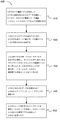
別の実施例は、図6のフローチャートに示されるように、デバイス間(D2D)通信を行うように動作可能なユーザ機器(UE)の機能600を提供する。機能は方法として実装することができ、または、機能は計算機上の命令として実行することができ、命令は少なくとも1つのコンピュータ可読媒体または1つの非一時的な機械可読記憶媒体に含まれる。UEは、ブロック610のように、UEのD2D無線ベアラを使用してUEから送信されるD2Dデータを識別し、D2DデータはUEが無線リソース制御(RRC)アイドルモードであるとき識別されるように構成された、1つまたは複数のプロセッサを含み得る。UEは、ブロック620のように、UEからD2Dデータを通信するためにUEが定義済リソース配分モードを使用することに限定されると決定するように構成された、1つまたは複数のプロセッサを含み得る。UEは、ブロック630のように、UEの非アクセス層(NAS)でサービス要求手順を開始し、サービス要求手順はUEをRRCアイドルモードからRRC接続モードに切り替えるためにUEのRRCレイヤが進化型ノードB(eNB)とRRC接続確立手順を行うことをトリガするように構成された、1つまたは複数のプロセッサを含み得る。UEは、ブロック640のように、UEからのD2Dデータの送信のためにeNBからアップリンク(UL)グラントを受信するように構成された、1つまたは複数のプロセッサを含み得る。UEは、ブロック650のように、eNBによって提供されたULグラントを使用してD2Dデータを送り、D2DデータはUEのD2D無線ベアラを使用してUEから送信されるように構成された、1つまたは複数のプロセッサを含み得る。
Another embodiment provides a user equipment (UE) function 600 operable to perform device-to-device (D2D) communication, as shown in the flowchart of FIG. A function may be implemented as a method, or a function may be executed as instructions on a computer, the instructions being included on at least one computer-readable medium or one non-transitory machine-readable storage medium. The UE identifies D2D data transmitted from the UE using the UE's D2D radio bearer, as in
1つの実施例において、1つまたは複数のプロセッサは、UEの媒体アクセス制御(MAC)レイヤからeNBにバッファ状態報告(BSR)を送ることに応じてeNBからULグラントを受信するようにさらに構成することができ、BSRは、UEがRRC接続モードに切り替わった後eNBに送られる。別の実施例において、1つまたは複数のプロセッサは、UEのMACレイヤからeNBにBSRを送るために定義済リソース配分モードと関連付けられた1つまたは複数の設定パラメータを使用するようにさらに構成することができ、1つまたは複数の設定パラメータは、周期的なD2D BSRタイマまたはD2D BSR再送信タイマのうちの少なくとも1つを含む。 In one embodiment, the one or more processors are further configured to receive a UL grant from the eNB in response to sending a buffer status report (BSR) from the UE's medium access control (MAC) layer to the eNB. And the BSR is sent to the eNB after the UE switches to RRC connected mode. In another embodiment, the one or more processors are further configured to use one or more configuration parameters associated with the defined resource allocation mode to send the BSR from the MAC layer of the UE to the eNB. The one or more configuration parameters may include at least one of a periodic D2D BSR timer or a D2D BSR retransmission timer.
1つの実施例において、1つまたは複数のプロセッサは、UEのためにシグナリング無線ベアラを作り出すためにUEのRRCレイヤでRRC接続確立手順を行うようにさらに構成することができる。別の実施例において、1つまたは複数のプロセッサは、UEのシグナリング無線ベアラを使用してeNBにサービス要求メッセージを送るようにさらに構成され、サービス要求メッセージはUEのためのセルラ無線ベアラの確立を要求するためのものである。さらに別の実施例において、定義済リソース配分モードはリソース配分モード1である。
In one embodiment, the one or more processors may be further configured to perform an RRC connection establishment procedure at the RRC layer of the UE to create a signaling radio bearer for the UE. In another embodiment, the one or more processors are further configured to send a service request message to the eNB using the UE's signaling radio bearer, the service request message confirming the establishment of a cellular radio bearer for the UE. It is for requesting. In yet another embodiment, the predefined resource allocation mode is
1つの実施例において、1つまたは複数のプロセッサは、eNBから報知されたシステム情報ブロック(SIB)に基づいてUEが定義済リソース配分モードを使用することに限定されると決定するようにさらに構成される。別の実施例において、D2D無線ベアラは、D2Dデータが第2のUEに送信されるために識別されるときUEのために存在し、D2D無線ベアラは定義済無線アクセス技術(RAT)規格を使用して動作する。さらに別の実施例において、D2DデータはUE上でD2Dアプリケーションによって生成される。 In one embodiment, the one or more processors are further configured to determine that the UE is limited to using the defined resource allocation mode based on a system information block (SIB) broadcast from the eNB. Is done. In another embodiment, a D2D radio bearer exists for a UE when D2D data is identified for transmission to a second UE, and the D2D radio bearer uses a defined radio access technology (RAT) standard Works. In yet another embodiment, D2D data is generated by the D2D application on the UE.
1つの実施例において、D2D無線ベアラは、UEがRRCアイドルモードであるとき存在する。別の実施例において、UEは進化型ユニバーサル地上無線アクセスネットワーク(E−UTRAN)で動作することができる。その上、1つまたは複数のプロセッサは、RRC接続確立手順の間にeNBにRRC接続要求メッセージを送るようにさらに構成することができ、RRC接続要求メッセージは、D2D通信を行うためにUEがRRC接続モードに切り替わるべきであるという指示を含む。1つの構成において、eNBがUEに対してアクセスクラス禁止を強制しているとき、UEは定義済の期間D2D通信を行うことを禁じられる。 In one embodiment, the D2D radio bearer is present when the UE is in RRC idle mode. In another example, the UE may operate in an evolved universal terrestrial radio access network (E-UTRAN). Moreover, the one or more processors can be further configured to send an RRC connection request message to the eNB during the RRC connection establishment procedure, where the RRC connection request message is received by the UE in order to perform D2D communication. Includes an indication that it should switch to connected mode. In one configuration, when the eNB forces the UE to prohibit access class, the UE is prohibited from performing D2D communication for a defined period.
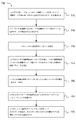
別の実施例は、図7のフローチャートに示されるように、デバイス間(D2D)通信を行うように動作可能なユーザ機器(UE)の機能700を提供する。機能は方法として実装することができ、または、機能は計算機上の命令として実行することができ、命令は少なくとも1つのコンピュータ可読媒体または1つの非一時的な機械可読記憶媒体に含まれる。UEは、ブロック710のように、UEが進化型ノードB(eNB)と無線リソース制御(RRC)接続モードである間にUEから送信されるD2Dデータを識別するように構成された、1つまたは複数のプロセッサを含み得る。UEは、ブロック720のように、D2Dデータを送信するためにUEが定義済リソース配分モードを使用することに限定されると決定するように構成された、1つまたは複数のプロセッサを含み得る。UEは、ブロック730のように、eNBにRRC設定要求メッセージを送るように構成された、1つまたは複数のプロセッサを含み得る。UEは、ブロック740のように、eNBからRRC接続再設定メッセージを受信し、RRC接続再設定メッセージは定義済リソース配分モードに対する1つまたは複数の設定パラメータを含むように構成された、1つまたは複数のプロセッサを含み得る。UEは、ブロック750のように、1つまたは複数の設定パラメータに従ってeNBにバッファ状態報告(BSR)を送るように構成された、1つまたは複数のプロセッサを含み得る。UEは、ブロック760のように、UEからのD2Dデータの送信のためにeNBからアップリンク(UL)グラントを受信するように構成された、1つまたは複数のプロセッサを含み得る。UEは、ブロック770のように、eNBによって提供されたULグラントを使用してD2Dデータを送り、D2DデータはUEのD2D無線ベアラを使用してUEから送信されるように構成された、1つまたは複数のプロセッサを含み得る。
Another embodiment provides a user equipment (UE)
1つの実施例において、RRC接続再設定メッセージの中の1つまたは複数の設定パラメータは、周期的なD2D BSRタイマまたはD2D BSR再送信タイマのうちの少なくとも1つを含む。別の実施例において、RRC設定要求メッセージは、D2Dリソース要求表示情報要素(IE)またはD2D設定要求表示IEを含む。さらに別の実施例において、1つまたは複数のプロセッサは、UEのシグナリング無線ベアラを使用してeNBにRRC設定要求メッセージを送るようにさらに構成することができる。1つの構成において、D2D無線ベアラは、D2Dデータが第2のUEに送信されるために識別されるときUEのために存在し、D2D無線ベアラは定義済無線アクセス技術(RAT)規格を使用して動作する。 In one embodiment, the one or more configuration parameters in the RRC connection reconfiguration message include at least one of a periodic D2D BSR timer or a D2D BSR retransmission timer. In another embodiment, the RRC setup request message includes a D2D resource request indication information element (IE) or a D2D setup request indication IE. In yet another example, the one or more processors may be further configured to send an RRC setup request message to the eNB using the UE's signaling radio bearer. In one configuration, a D2D radio bearer exists for a UE when D2D data is identified for transmission to a second UE, and the D2D radio bearer uses a defined radio access technology (RAT) standard. Works.
別の実施例は、図8のフローチャートに示されるように、デバイス間(D2D)通信を行うための方法800を提供する。方法は、計算機上の命令として実行することができ、命令は、少なくとも1つのコンピュータ可読媒体または1つの非一時的な機械可読記憶媒体に含まれる。方法は、ブロック810のように、送信先UEに通信されるD2Dデータを、ユーザ機器(UE)で、識別する動作であって、D2DデータはUEが無線リソース制御(RRC)アイドルモードであるとき識別される、動作を含み得る。方法は、ブロック820のように、送信先UEにD2Dデータを通信するためにUEが定義済リソース配分モードを使用することに限定されると決定する動作を含み得る。方法は、ブロック830のように、UEでサービス要求手順を開始する動作であって、サービス要求手順はUEをRRCアイドルモードからRRC接続モードに切り替えるためにUEが進化型ノードB(eNB)とRRC接続確立手順を行うことをトリガする、動作を含み得る。方法は、ブロック840のように、送信先UEにD2Dデータを通信するためにeNBからアップリンク(UL)グラントを受信する動作を含み得る。方法は、ブロック850のように、eNBによって提供されたULグラントを使用して送信先UEにD2Dデータを送る動作であって、D2DデータはUEのD2D無線ベアラを使用して送信先UEに通信される、動作を含み得る。
Another embodiment provides a
1つの実施例において、方法は、UEからeNBにバッファ状態報告(BSR)を送ることに応じてeNBからULグラントを、UEで、受信する動作を含むことができ、BSRは、UEがRRC接続モードに切り替わった後eNBに送られる。別の実施例において、方法は、定義済リソース配分モードと関連付けられた1つまたは複数の設定パラメータを使用してUEからeNBにBSRを送る動作を含むことができ、1つまたは複数の設定パラメータは、周期的なD2D BSRタイマまたはD2D BSR再送信タイマのうちの少なくとも1つを含む。さらに別の実施例において、方法は、UEのシグナリング無線ベアラを使用してUEからeNBにサービス要求メッセージを送る動作を含むことができ、シグナリング無線ベアラはRRC接続確立手順の間にUEのために確立され、サービス要求メッセージはUEのためにセルラ無線ベアラを確立するためのものである。その上、方法は、eNBから報知されたシステム情報ブロック(SIB)に基づいてUEが定義済リソース配分モードを使用することに限定されると決定する動作を含み得る。1つの構成において、方法は、UEの隣接するセルがD2D通信をサポートするかどうかに基づいてセル再選択を行う動作を含み得る。 In one embodiment, the method can include an operation of receiving, at the UE, a UL grant from the eNB in response to sending a buffer status report (BSR) from the UE to the eNB, wherein the BSR is a UE connected to the RRC. After switching to the mode, it is sent to the eNB. In another example, the method can include an act of sending a BSR from the UE to the eNB using one or more configuration parameters associated with a defined resource allocation mode. Includes at least one of a periodic D2D BSR timer or a D2D BSR retransmission timer. In yet another example, the method may include an operation of sending a service request message from the UE to the eNB using the UE's signaling radio bearer, the signaling radio bearer for the UE during the RRC connection establishment procedure. The established service request message is for establishing a cellular radio bearer for the UE. Moreover, the method may include an act of determining that the UE is limited to using the defined resource allocation mode based on a system information block (SIB) broadcast from the eNB. In one configuration, the method may include performing cell reselection based on whether a neighboring cell of the UE supports D2D communication.
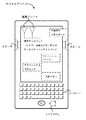
図9は、ユーザ機器(UE)、移動局(MS)、モバイル・ワイヤレス・デバイス、モバイル通信デバイス、タブレット、ハンドセット、または他のタイプのワイヤレスデバイスなどの、ワイヤレスデバイスの実施例の説明図を提供する。ワイヤレスデバイスは、ノード、マクロノード、低電力ノード(LPN)、または、基地局(BS)、進化型Node B(eNB)、ベースバンドユニット(BBU)、リモート無線ヘッド(RRH)、リモート無線機器(RRE)、中継局(RS)、無線機器(RE)、もしくは他のタイプのワイヤレス広域ネットワーク(WWAN)アクセスポイントなどの送信局と通信するように構成された、1つまたは複数のアンテナを含み得る。ワイヤレスデバイスは、3GPP LTE、WiMAX、高速パケットアクセス(HSPA)、ブルートゥース(登録商標)、およびWiFiを含む、少なくとも1つのワイヤレス通信規格を使用して通信するように構成することができる。ワイヤレスデバイスは、各々のワイヤレス通信規格に対する別個のアンテナ、または多数のワイヤレス通信規格に対する共有アンテナを使用して通信することができる。ワイヤレスデバイスは、ワイヤレス・ローカル・エリア・ネットワーク(WLAN)、ワイヤレス・パーソナル・エリア・ネットワーク(WPAN)、および/またはWWANで通信することができる。 FIG. 9 provides an illustration of an example of a wireless device, such as a user equipment (UE), mobile station (MS), mobile wireless device, mobile communications device, tablet, handset, or other type of wireless device To do. A wireless device can be a node, a macro node, a low power node (LPN), or a base station (BS), evolved Node B (eNB), baseband unit (BBU), remote radio head (RRH), remote radio equipment ( RRE), a relay station (RS), a radio equipment (RE), or one or more antennas configured to communicate with a transmitting station such as other types of wireless wide area network (WWAN) access points . The wireless device can be configured to communicate using at least one wireless communication standard, including 3GPP LTE, WiMAX, High Speed Packet Access (HSPA), Bluetooth, and WiFi. Wireless devices can communicate using a separate antenna for each wireless communication standard or a shared antenna for multiple wireless communication standards. A wireless device may communicate over a wireless local area network (WLAN), a wireless personal area network (WPAN), and / or a WWAN.
図9は、ワイヤレスデバイスからのオーディオ入出力のために使用することができるマイクロホンおよび1つまたは複数のスピーカの説明図を同様に提供する。表示画面は、液晶ディスプレイ(LCD)画面、または有機発光ダイオード(OLED)ディスプレイなどの他のタイプの表示画面とすることができる。表示画面はタッチスクリーンとして構成することができる。タッチスクリーンは、容量性、抵抗性、または別のタイプのタッチスクリーン技術を使用することができる。アプリケーションプロセッサおよびグラフィックスプロセッサは、処理能力および表示能力を提供するために内部メモリに結合することができる。不揮発性メモリポートは、ユーザにデータ入力/出力オプションを提供するために同様に使用することができる。不揮発性メモリポートは、ワイヤレスデバイスの記憶能力を拡充するために同様に使用することができる。キーボードは、さらなるユーザ入力を提供するために、ワイヤレスデバイスと一体化するか、またはワイヤレスデバイスにワイヤレス接続することができる。タッチスクリーンを使用して仮想キーボードを同様に提供することができる。 FIG. 9 similarly provides an illustration of a microphone and one or more speakers that can be used for audio input and output from a wireless device. The display screen can be a liquid crystal display (LCD) screen or other type of display screen such as an organic light emitting diode (OLED) display. The display screen can be configured as a touch screen. The touch screen can use capacitive, resistive, or another type of touch screen technology. Application processors and graphics processors can be coupled to internal memory to provide processing and display capabilities. Non-volatile memory ports can be used as well to provide data input / output options to the user. Nonvolatile memory ports can be used as well to expand the storage capabilities of wireless devices. The keyboard can be integrated with or wirelessly connected to the wireless device to provide further user input. A virtual keyboard can be provided as well using a touch screen.
さまざまな技術、またはその一定の実施態様もしくは部分は、フロッピーディスケット、CD−ROM、ハードドライブ、非一時的コンピュータ可読記憶媒体、または任意の他の機械可読記憶媒体などの有形の媒体に具体化されたプログラムコード(すなわち、命令)の形をとることができ、プログラムコードがコンピュータなどの計算機にロードされこの計算機によって実行されるとき、計算機はさまざまな技術を実践するための装置になる。回路は、ハードウェア、ファームウェア、プログラムコード、実行可能なコード、コンピュータ命令、および/またはソフトウェアを含み得る。非一時的コンピュータ可読記憶媒体は、信号を含まないコンピュータ可読記憶媒体とすることができる。プログラム可能なコンピュータ上でプログラムコードを実行する場合、コンピューティングデバイスは、プロセッサ、(揮発性および不揮発性のメモリおよび/または記憶要素を含む)プロセッサによって読み取り可能な記憶媒体、少なくとも1つの入力デバイス、および少なくとも1つの出力デバイスを含み得る。揮発性および不揮発性のメモリおよび/または記憶要素は、RAM、EPROM、フラッシュドライブ、光学ドライブ、磁気ディスクドライブ、ソリッド・ステート・ドライブ、または電子データを格納するための他の媒体とすることができる。ノードおよびワイヤレスデバイスは、トランシーバモジュール、カウンタモジュール、処理モジュール、および/またはクロックモジュールもしくはタイマモジュールを同様に含み得る。本明細書で説明されたさまざまな技術を実装または利用することができる1つまたは複数のプログラムは、アプリケーション・プログラミング・インタフェース(API)、再利用可能な制御などを使用することができる。このようなプログラムは、コンピュータシステムと通信するために高レベルの手続き型またはオブジェクト指向プログラミング言語で実装することができる。しかしながら、必要に応じて、プログラムはアセンブリまたは機械言語で実装してもよい。いずれにしても、言語はコンパイル型またはインタープリタ型言語とすることができ、ハードウェア実装と組み合わせることができる。 Various techniques, or certain embodiments or portions thereof, may be embodied in a tangible medium such as a floppy diskette, CD-ROM, hard drive, non-transitory computer readable storage medium, or any other machine readable storage medium. Program code (ie, instructions), and when the program code is loaded into and executed by a computer such as a computer, the computer becomes a device for practicing various techniques. The circuitry may include hardware, firmware, program code, executable code, computer instructions, and / or software. The non-transitory computer readable storage medium may be a computer readable storage medium that does not include signals. When executing program code on a programmable computer, the computing device includes a processor, a storage medium readable by the processor (including volatile and non-volatile memory and / or storage elements), at least one input device, And at least one output device. Volatile and non-volatile memory and / or storage elements can be RAM, EPROM, flash drives, optical drives, magnetic disk drives, solid state drives, or other media for storing electronic data. . Nodes and wireless devices may also include transceiver modules, counter modules, processing modules, and / or clock modules or timer modules. One or more programs that can implement or utilize the various techniques described herein can use application programming interfaces (APIs), reusable controls, and the like. Such programs can be implemented in a high level procedural or object oriented programming language to communicate with a computer system. However, if necessary, the program may be implemented in assembly or machine language. In any case, the language can be a compiled or interpreted language and can be combined with a hardware implementation.
本明細書で説明された機能ユニットの多くは、それらの実装独立性をより具体的に強調するためにモジュールとしてラベル付けされていることを理解すべきである。例えば、モジュールは、カスタムVLSI回路またはゲートアレイ、ロジックチップなどの既成の半導体、トランジスタ、または他の個別部品を含むハードウェア回路として実装することができる。モジュールは同様に、フィールド・プログラマブル・ゲート・アレイ、プログラマブル・アレイ・ロジック、プログラマブル・ロジック・デバイスなどの、プログラム可能なハードウェアデバイスで実装することができる。 It should be understood that many of the functional units described herein are labeled as modules to more specifically emphasize their implementation independence. For example, the module can be implemented as a custom VLSI circuit or hardware circuit including a gate array, off-the-shelf semiconductors such as logic chips, transistors, or other discrete components. Modules can also be implemented with programmable hardware devices, such as field programmable gate arrays, programmable array logic, programmable logic devices, and the like.
モジュールは同様に、さまざまなタイプのプロセッサによる実行のためにソフトウェアで実装することができる。実行可能なコードの識別されたモジュールは、例えば、コンピュータ命令の1つまたは複数の物理ブロックまたは論理ブロックを含むことができ、それらは、例えば、オブジェクト、手順、または関数として組織化することができる。それにもかかわらず、識別されたモジュールの実行ファイルは、物理的に一緒に位置している必要はなく、論理的に一緒に結合されたときに、モジュールを含みモジュールに対する規定の目的を達成する、異なる場所に格納された異種の命令を含むことができる。 Modules can also be implemented in software for execution by various types of processors. The identified modules of executable code can include, for example, one or more physical or logical blocks of computer instructions, which can be organized as, for example, objects, procedures, or functions. . Nevertheless, the identified module executables do not have to be physically located together, but, when combined logically together, achieve the specified purpose for the module, including the module, It can contain disparate instructions stored at different locations.
実際に、実行可能なコードのモジュールは、単一の命令であっても多くの命令であってもよく、異なるプログラムの中に、そしていくつかのメモリデバイスにわたって、いくつかの異なるコードセグメントに分散されてもよい。同様に、運用データは、ここではモジュールの中で識別され例示されてもよく、任意の適当な形で具体化され任意の適当なタイプのデータ構造の中で組織化されてもよい。運用データは、単一のデータセットとして収集されてもよく、または異なる記憶デバイス上を含む異なる場所上に分散されてもよく、少なくとも部分的に、単にシステムまたはネットワーク上の電子信号として存在してもよい。モジュールは、望ましい機能を行うように動作可能なエージェントを含み、受動的であっても能動的であってもよい。 In practice, a module of executable code can be a single instruction or many instructions, distributed in different programs and across several memory devices, in several different code segments. May be. Similarly, operational data may be identified and exemplified herein in modules, embodied in any suitable form, and organized in any suitable type of data structure. Operational data may be collected as a single data set or distributed over different locations, including on different storage devices, and at least partly exists simply as an electronic signal on a system or network Also good. Modules include agents that are operable to perform desired functions, and may be passive or active.
本明細書で使用される、用語「プロセッサ」は、ワイヤレス通信を送り、受信し、処理するためにトランシーバで使用されるベース・バンド・プロセッサと同様、汎用プロセッサ、VLSIなどの専門的なプロセッサ、FPGA、および他のタイプの専門的なプロセッサを含み得る。 As used herein, the term “processor” refers to a general purpose processor, a specialized processor such as a VLSI, as well as a baseband processor used in a transceiver to send, receive and process wireless communications. It may include FPGAs and other types of specialized processors.
本明細書全体を通して、「実施例」への言及は、その実施例に関連して説明された特定の機能、構造、または特性が本発明の少なくとも1つの実施形態に含まれることを意味する。したがって、本明細書全体を通して各所における「実施例において」という句の出現は、必ずしもすべて同じ実施形態を意味していない。 Throughout this specification, reference to “an example” means that the particular function, structure, or characteristic described in connection with that example is included in at least one embodiment of the invention. Thus, the appearances of the phrase “in an example” in various places throughout this specification are not necessarily all referring to the same embodiment.
本明細書で使用される、複数の項目、構造的な要素、構成要素、および/または材料は、便宜上共通のリストで提示され得る。しかしながら、これらのリストは、リストの各々のメンバが別個の固有のメンバとして個々に識別されるように解釈されるべきである。したがって、このようなリストの個々のメンバは、反対の指示がない限り、それらが共通のグループで提示されることに単に基づいて、同じリストの任意の他のメンバの事実上の均等物であると解釈されるべきでない。その上、本発明のさまざまな実施形態および実施例は、そのさまざまな構成要素に対して代替物とともに、本明細書で言及され得る。このような実施形態、実施例、および代替物は、互いの事実上の均等物として解釈されるべきではなく、本発明の別個の自律的な表現とみなされるべきであることが理解される。 As used herein, multiple items, structural elements, components, and / or materials may be presented in a common list for convenience. However, these lists should be interpreted so that each member of the list is individually identified as a separate unique member. Thus, individual members of such lists are the virtual equivalent of any other member of the same list, based solely on their being presented in a common group, unless indicated to the contrary Should not be interpreted. Moreover, various embodiments and examples of the invention may be referred to herein, along with alternatives to their various components. It is understood that such embodiments, examples, and alternatives should not be construed as a virtual equivalent to each other, but instead be considered as separate autonomous representations of the invention.
さらに、説明された機能、構造、または特性は、1つまたは複数の実施形態において、任意の適当なやり方で組み合わせることができる。次の説明で、本発明の実施形態の完全な理解を提供するために、レイアウトの実施例、距離、ネットワーク実施例などの、多数の特定の細部が提供される。当業者は、しかしながら、本発明が特定の細部のうちの1つまたは複数なしで実践されてもよく、または他の方法、構成要素、レイアウトなどを用いて実践されてもよいことを認識するであろう。他の例において、本発明の実施態様を不明瞭にすることを回避するために、周知の構造、材料、または動作については、図示または詳細な説明をしない。 Furthermore, the described functions, structures, or characteristics may be combined in any suitable manner in one or more embodiments. In the following description, numerous specific details are provided, such as layout examples, distances, network examples, etc., in order to provide a thorough understanding of embodiments of the present invention. Those skilled in the art will recognize, however, that the invention may be practiced without one or more of the specific details, or may be practiced with other methods, components, layouts, and the like. I will. In other instances, well-known structures, materials, or operations are not shown or described in detail to avoid obscuring embodiments of the invention.
前述の実施例は、1つまたは複数の特定用途で本発明の原理を例示しているが、発明的才能を行使することなく、そして本発明の原理および思想から逸脱することなく、実装の形、使用法および細部に多数の修正がなされ得ることは、当業者には明らかであろう。したがって、以下に明記された特許請求の範囲による場合を除き、本発明が限定されることを意図しない。 The foregoing examples illustrate the principles of the present invention in one or more specific applications, but the form of implementation may be used without exercising inventive talent and without departing from the principles and ideas of the present invention. It will be apparent to those skilled in the art that numerous modifications can be made to the usage and details. Accordingly, it is not intended that the invention be limited except as by the appended claims.
Claims (23)
前記UEのD2D無線ベアラを使用して前記UEから送信されるD2Dデータを識別し、前記D2Dデータは前記UEが無線リソース制御(RRC)アイドルモードであるとき識別され、
前記UEから前記D2Dデータを通信するために前記UEが定義済リソース配分モードを使用することに限定されると決定し、
前記UEの非アクセス層(NAS)でサービス要求手順を開始し、前記サービス要求手順は前記UEを前記RRCアイドルモードからRRC接続モードに切り替えるために前記UEのRRCレイヤが進化型ノードB(eNB)とRRC接続確立手順を行うことをトリガし、
前記UEからの前記D2Dデータの送信のために前記eNBからアップリンク(UL)グラントを受信し、
前記eNBによって提供された前記ULグラントを使用して前記D2Dデータを送り、前記D2Dデータは前記UEの前記D2D無線ベアラを使用して前記UEから送信される、
ように構成された、1つまたは複数のプロセッサを備える、ユーザ機器(UE)。 User equipment (UE) operable to perform device-to-device (D2D) communication, wherein the UE
Identifying D2D data transmitted from the UE using the UE's D2D radio bearer, wherein the D2D data is identified when the UE is in a radio resource control (RRC) idle mode;
Determining that the UE is limited to using a predefined resource allocation mode to communicate the D2D data from the UE;
Initiating a service request procedure in the non-access layer (NAS) of the UE, wherein the RRC layer of the UE is an evolved Node B (eNB) to switch the UE from the RRC idle mode to the RRC connected mode Trigger the RRC connection establishment procedure with
Receiving an uplink (UL) grant from the eNB for transmission of the D2D data from the UE;
Sending the D2D data using the UL grant provided by the eNB, and the D2D data is transmitted from the UE using the D2D radio bearer of the UE;
A user equipment (UE) comprising one or more processors configured as described above.
前記UEが進化型ノードB(eNB)と無線リソース制御(RRC)接続モードである間に前記UEから送信されるD2Dデータを識別し、
前記D2Dデータを送信するために前記UEが定義済リソース配分モードを使用することに限定されると決定し、
前記eNBにRRC設定要求メッセージを送り、
前記eNBからRRC接続再設定メッセージを受信し、前記RRC接続再設定メッセージは前記定義済リソース配分モードに対する1つまたは複数の設定パラメータを含み、
前記1つまたは複数の設定パラメータに従って前記eNBにバッファ状態報告(BSR)を送り、
前記UEからの前記D2Dデータの送信のために前記eNBからアップリンク(UL)グラントを受信し、
前記eNBによって提供された前記ULグラントを使用して前記D2Dデータを送り、前記D2Dデータは前記UEのD2D無線ベアラを使用して前記UEから送信される、
ように構成された、1つまたは複数のプロセッサを備える、ユーザ機器(UE)。 User equipment (UE) operable to perform device-to-device (D2D) communication, wherein the UE
Identifying D2D data transmitted from the UE while the UE is in evolved Node B (eNB) and Radio Resource Control (RRC) connection mode;
Determining that the UE is limited to using a predefined resource allocation mode to transmit the D2D data;
Send an RRC configuration request message to the eNB;
Receiving an RRC connection reconfiguration message from the eNB, wherein the RRC connection reconfiguration message includes one or more configuration parameters for the defined resource allocation mode;
Send a buffer status report (BSR) to the eNB according to the one or more configuration parameters;
Receiving an uplink (UL) grant from the eNB for transmission of the D2D data from the UE;
Sending the D2D data using the UL grant provided by the eNB, wherein the D2D data is transmitted from the UE using the UE's D2D radio bearer;
A user equipment (UE) comprising one or more processors configured as described above.
送信先UEに通信されるD2Dデータを、ユーザ機器(UE)で、識別するステップであって、前記D2Dデータは前記UEが進化型ノードB(eNB)と無線リソース制御(RRC)アイドルモードであるとき識別される、ステップと、
前記送信先UEに前記D2Dデータを通信するために前記UEが定義済リソース配分モードを使用することに限定されると決定するステップと、
前記UEでサービス要求手順を開始するステップであって、前記サービス要求手順は前記UEを前記RRCアイドルモードからRRC接続モードに切り替えるために前記UEが前記eNBとRRC接続確立手順を行うことをトリガする、ステップと、
前記送信先UEに前記D2Dデータを通信するために前記eNBからアップリンク(UL)グラントを受信するステップと、
前記eNBによって提供された前記ULグラントを使用して前記送信先UEに前記D2Dデータを送るステップであって、前記D2Dデータは前記UEのD2D無線ベアラを使用して前記送信先UEに通信される、ステップと、
を含む、方法。 A method for performing device-to-device (D2D) communication, the method comprising:
Identifying D2D data communicated to a destination UE at user equipment (UE), wherein the UE is in evolved Node B (eNB) and radio resource control (RRC) idle mode When identified, with steps,
Determining that the UE is limited to using a defined resource allocation mode to communicate the D2D data to the destination UE;
Initiating a service request procedure at the UE, the service request procedure triggering the UE to perform an RRC connection establishment procedure with the eNB to switch the UE from the RRC idle mode to an RRC connection mode. , Steps and
Receiving an uplink (UL) grant from the eNB to communicate the D2D data to the destination UE;
Sending the D2D data to the destination UE using the UL grant provided by the eNB, wherein the D2D data is communicated to the destination UE using the UE's D2D radio bearer , Steps and
Including the method.
Applications Claiming Priority (5)
| Application Number | Priority Date | Filing Date | Title |
|---|---|---|---|
| US201461990679P | 2014-05-08 | 2014-05-08 | |
| US61/990,679 | 2014-05-08 | ||
| US14/583,030 US9661653B2 (en) | 2014-05-08 | 2014-12-24 | Device to-device (D2D) communications |
| US14/583,030 | 2014-12-24 | ||
| PCT/US2015/024223 WO2015171230A1 (en) | 2014-05-08 | 2015-04-03 | Device-to-device (d2d) communications |
Publications (2)
| Publication Number | Publication Date |
|---|---|
| JP2017517199A true JP2017517199A (en) | 2017-06-22 |
| JP6381674B2 JP6381674B2 (en) | 2018-08-29 |
Family
ID=54369095
Family Applications (1)
| Application Number | Title | Priority Date | Filing Date |
|---|---|---|---|
| JP2016566755A Active JP6381674B2 (en) | 2014-05-08 | 2015-04-03 | Device-to-device (D2D) communication |
Country Status (11)
| Country | Link |
|---|---|
| US (2) | US9661653B2 (en) |
| EP (1) | EP3141077A4 (en) |
| JP (1) | JP6381674B2 (en) |
| KR (1) | KR20160131068A (en) |
| AU (1) | AU2015256559B2 (en) |
| CA (1) | CA2945140C (en) |
| MX (1) | MX360478B (en) |
| MY (1) | MY190967A (en) |
| RU (1) | RU2643699C1 (en) |
| TW (1) | TWI583236B (en) |
| WO (1) | WO2015171230A1 (en) |
Cited By (2)
| Publication number | Priority date | Publication date | Assignee | Title |
|---|---|---|---|---|
| WO2021024333A1 (en) * | 2019-08-02 | 2021-02-11 | 株式会社Nttドコモ | Terminal and communication method |
| JP2022549614A (en) * | 2019-09-20 | 2022-11-28 | 大唐移▲動▼通信▲設▼▲備▼有限公司 | Direct communication interface bearer configuration change method and terminal |
Families Citing this family (34)
| Publication number | Priority date | Publication date | Assignee | Title |
|---|---|---|---|---|
| WO2015171063A1 (en) * | 2014-05-08 | 2015-11-12 | Telefonaktiebolaget L M Ericsson (Publ) | Method and apparatus for controlling the activity state of a wireless device having device-to-device communication capabilities |
| US9923834B2 (en) * | 2014-05-09 | 2018-03-20 | Futurewei Technologies, Inc. | System and method for triggering and sending device-to-device buffer status report and scheduling request |
| EP3140980B1 (en) * | 2014-05-09 | 2020-08-19 | Sony Corporation | System, base station, and method of enabling usage of resources for a device-to-device discovery |
| US20170086238A1 (en) * | 2014-05-15 | 2017-03-23 | Lg Electronics Inc. | As-nas interaction method for d2d communication and apparatus for the same in wireless communication system |
| US20150341938A1 (en) * | 2014-05-22 | 2015-11-26 | Qualcomm Incorporated | Uplink operation for rlc communications |
| US10225872B2 (en) * | 2014-06-17 | 2019-03-05 | Htc Corporation | Device and method of handling device-to-device communication |
| EP3162137B1 (en) * | 2014-06-26 | 2021-03-10 | Nokia Solutions and Networks Oy | Radio resource allocation for proximity services |
| WO2016003199A1 (en) * | 2014-07-01 | 2016-01-07 | 엘지전자 주식회사 | Method for performing d2d communication in wireless communication system and device therefor |
| US9907056B2 (en) | 2014-08-06 | 2018-02-27 | Futurewei Technologies, Inc. | System and method for allocating resources for device-to-device communications |
| US10231279B2 (en) * | 2014-08-08 | 2019-03-12 | Telefonaktiebolaget Lm Ericsson (Publ) | Handling D2D resource grant procedures |
| US10057918B2 (en) * | 2014-08-08 | 2018-08-21 | Telefonaktiebolaget Lm Ericsson (Publ) | Coordination between prose BSR and cellular BSR |
| US9591686B2 (en) | 2014-08-11 | 2017-03-07 | Qualcomm Incorporated | Access class barring for device-to-device proximity service communications |
| US10681525B2 (en) * | 2014-09-25 | 2020-06-09 | Intel IP Corporation | Access control mechanisms for D2D discovery and communication |
| WO2016045091A1 (en) | 2014-09-26 | 2016-03-31 | Panasonic Intellectual Property Corporation Of America | Device-to-device wireless communication method and user equipment |
| CN107079506B (en) * | 2014-10-31 | 2020-06-05 | 索尼公司 | User equipment, communication system, and method of controlling user equipment |
| CN107148800B (en) * | 2014-11-03 | 2020-12-22 | Lg电子株式会社 | Apparatus-to-apparatus terminal signal transmission method and apparatus in wireless communication system |
| US20160135246A1 (en) * | 2014-11-06 | 2016-05-12 | Microsoft Corporation | Handling of device-to-device communications interest indication |
| JP6110575B2 (en) | 2014-11-07 | 2017-04-05 | 京セラ株式会社 | User terminal and device |
| US10433317B2 (en) * | 2014-11-25 | 2019-10-01 | Lg Electronics Inc. | Method for assisting device-to-device communication in wireless communication system supporting device-to-device communication and device therefor |
| KR102269387B1 (en) * | 2015-01-06 | 2021-06-25 | 삼성전자주식회사 | Information sharing method depends on a situation and electronic device supporting the same |
| KR102314442B1 (en) | 2015-02-06 | 2021-10-19 | 삼성전자주식회사 | System and method of user equipment discovery in device-to-device networks |
| US10200846B2 (en) * | 2015-03-24 | 2019-02-05 | Samsung Electronics Co., Ltd. | Method and apparatus for transmitting and receiving message in wireless communication system |
| EP3282772B1 (en) * | 2015-04-10 | 2021-05-26 | Kyocera Corporation | User terminal and wireless base station |
| EP3324698B1 (en) * | 2015-07-15 | 2020-09-02 | LG Electronics Inc. | Method and apparatus for transmitting and receiving data, by terminal, in wireless communication system |
| PT3331301T (en) * | 2015-08-13 | 2021-05-19 | Ntt Docomo Inc | User device and signal transmission method |
| US10477516B2 (en) * | 2015-10-08 | 2019-11-12 | Telefonaktiebolaget Lm Ericsson (Publ) | Device to device operation in out of network coverage |
| CN105517191B (en) * | 2016-01-07 | 2019-04-12 | 宇龙计算机通信科技(深圳)有限公司 | Connection management method and device, terminal and base station in D2D relayed communications |
| JP6763404B2 (en) * | 2016-01-08 | 2020-09-30 | 富士通株式会社 | Wireless communication devices, wireless communication systems and processing methods |
| EP3457726B1 (en) * | 2016-06-03 | 2021-08-04 | Huawei Technologies Co., Ltd. | Method for transmitting information, user equipment, access network device, and core network device |
| WO2018088832A1 (en) * | 2016-11-11 | 2018-05-17 | 엘지전자 주식회사 | Method and apparatus for configuring rrc connection establishment cause for relay terminal in idle state in wireless communication system |
| CN109756986B (en) | 2017-11-03 | 2021-07-13 | 大唐移动通信设备有限公司 | Uplink data packet resource allocation method and user terminal |
| CN110839299B (en) * | 2018-08-16 | 2022-04-01 | 大唐移动通信设备有限公司 | Resource allocation method and equipment |
| CN111328069B (en) * | 2018-12-17 | 2022-05-03 | 大唐移动通信设备有限公司 | Resource allocation mode configuration method, terminal and network equipment |
| EP4018751A1 (en) * | 2019-10-02 | 2022-06-29 | Ofinno, LLC | Sidelink bearer mode change by a wireless device |
Citations (4)
| Publication number | Priority date | Publication date | Assignee | Title |
|---|---|---|---|---|
| JP2010081597A (en) * | 2008-09-26 | 2010-04-08 | Asustek Computer Inc | Method and apparatus of handling timer for triggering buffer status report |
| US20120184306A1 (en) * | 2009-09-28 | 2012-07-19 | Nokia Corporation | Random Access Process Reusing For D2D Probing in Cellular-Aided D2D Networks |
| JP2013507025A (en) * | 2009-10-02 | 2013-02-28 | リサーチ イン モーション リミテッド | Determining the cause of an emergency session |
| WO2014014326A1 (en) * | 2012-07-20 | 2014-01-23 | Lg Electronics Inc. | Method and apparatus for transmitting device-to-device related message in wireless communication system |
Family Cites Families (10)
| Publication number | Priority date | Publication date | Assignee | Title |
|---|---|---|---|---|
| BR0211884A (en) * | 2001-08-13 | 2004-09-21 | Qualcomm Inc | Using Permissions to Allocate Device Resources for an Application |
| US7669177B2 (en) * | 2003-10-24 | 2010-02-23 | Microsoft Corporation | System and method for preference application installation and execution |
| US9992009B2 (en) * | 2009-04-24 | 2018-06-05 | Telefonaktiebolaget Lm Ericsson (Publ) | Method and apparatus for performing uplink transmissions in a wireless communications system |
| CN101932029A (en) * | 2010-08-13 | 2010-12-29 | 华为技术有限公司 | Data transmission method, equipment and system |
| WO2012109529A1 (en) * | 2011-02-11 | 2012-08-16 | Interdigital Patent Holdings, Inc. | Method and apparatus for uplink closed loop transmit diversity transmission initial access |
| GB2514650B (en) * | 2012-03-23 | 2018-05-09 | Lg Electronics Inc | Method of saving PLMN information of a user equipment in a wireless communication system and apparatus therefor |
| KR102461556B1 (en) * | 2012-08-23 | 2022-10-31 | 인터디지탈 패튼 홀딩스, 인크 | Method and apparatus for performing device-to-device discovery |
| US8989092B2 (en) * | 2012-10-04 | 2015-03-24 | Futurewei Technologies, Inc. | Signaling control for reduced signaling storm and improved user equipment battery life |
| US9924503B2 (en) * | 2012-10-09 | 2018-03-20 | Snu R&Db Foundation | Method and apparatus for performing device-to-device communication in wireless communication system |
| EP2983425B1 (en) * | 2014-08-08 | 2019-03-06 | Panasonic Intellectual Property Corporation of America | D2D Data Transmission - Timing Advance for Idle Mode UE |
-
2014
- 2014-12-24 US US14/583,030 patent/US9661653B2/en not_active Expired - Fee Related
-
2015
- 2015-04-02 TW TW104110916A patent/TWI583236B/en active
- 2015-04-03 MY MYPI2016703690A patent/MY190967A/en unknown
- 2015-04-03 AU AU2015256559A patent/AU2015256559B2/en not_active Ceased
- 2015-04-03 MX MX2016013217A patent/MX360478B/en active IP Right Grant
- 2015-04-03 KR KR1020167027796A patent/KR20160131068A/en active Search and Examination
- 2015-04-03 WO PCT/US2015/024223 patent/WO2015171230A1/en active Application Filing
- 2015-04-03 CA CA2945140A patent/CA2945140C/en active Active
- 2015-04-03 JP JP2016566755A patent/JP6381674B2/en active Active
- 2015-04-03 RU RU2016139436A patent/RU2643699C1/en not_active IP Right Cessation
- 2015-04-03 EP EP15788732.4A patent/EP3141077A4/en not_active Withdrawn
-
2017
- 2017-04-20 US US15/492,890 patent/US10028301B2/en active Active
Patent Citations (4)
| Publication number | Priority date | Publication date | Assignee | Title |
|---|---|---|---|---|
| JP2010081597A (en) * | 2008-09-26 | 2010-04-08 | Asustek Computer Inc | Method and apparatus of handling timer for triggering buffer status report |
| US20120184306A1 (en) * | 2009-09-28 | 2012-07-19 | Nokia Corporation | Random Access Process Reusing For D2D Probing in Cellular-Aided D2D Networks |
| JP2013507025A (en) * | 2009-10-02 | 2013-02-28 | リサーチ イン モーション リミテッド | Determining the cause of an emergency session |
| WO2014014326A1 (en) * | 2012-07-20 | 2014-01-23 | Lg Electronics Inc. | Method and apparatus for transmitting device-to-device related message in wireless communication system |
Non-Patent Citations (5)
| Title |
|---|
| "Radio Resource Control(RRC);Protocol specification(Release10)", 3GPP TS 36.331 V10.12.0, JPN6017043709, December 2013 (2013-12-01), pages 21 - 38, ISSN: 0003681451 * |
| ETRI: "Fully scheduled D2D transmission in LTE-coverage[online]", 3GPP TSG-RAN WG2#84 R2-134095, JPN6017043710, 15 November 2013 (2013-11-15), ISSN: 0003681452 * |
| ETRI: "Procedure for Mode 1 D2D communication[online]", 3GPP TSG-RAN WG2♯85BIS R2-141473, JPN6017043707, 4 April 2014 (2014-04-04), ISSN: 0003681450 * |
| INTEL CORPORATION: "Resource allocation for D2D discovery[online]", 3GPP TSG-RAN WG2#83BIS R2-133512, JPN6017043712, 11 October 2013 (2013-10-11), ISSN: 0003681453 * |
| SAMSUNG: "Mode 1 resource allocation for D2D broadcast communication[online]", 3GPP TSG-RAN WG1♯76B R1-141307, JPN6017043706, 4 April 2014 (2014-04-04), ISSN: 0003681449 * |
Cited By (3)
| Publication number | Priority date | Publication date | Assignee | Title |
|---|---|---|---|---|
| WO2021024333A1 (en) * | 2019-08-02 | 2021-02-11 | 株式会社Nttドコモ | Terminal and communication method |
| JP2022549614A (en) * | 2019-09-20 | 2022-11-28 | 大唐移▲動▼通信▲設▼▲備▼有限公司 | Direct communication interface bearer configuration change method and terminal |
| JP7498770B2 (en) | 2019-09-20 | 2024-06-12 | 大唐移▲動▼通信▲設▼▲備▼有限公司 | Direct communication interface bearer configuration change method and terminal |
Also Published As
| Publication number | Publication date |
|---|---|
| JP6381674B2 (en) | 2018-08-29 |
| US9661653B2 (en) | 2017-05-23 |
| KR20160131068A (en) | 2016-11-15 |
| EP3141077A1 (en) | 2017-03-15 |
| EP3141077A4 (en) | 2017-12-13 |
| MX2016013217A (en) | 2017-08-15 |
| TW201543947A (en) | 2015-11-16 |
| TWI583236B (en) | 2017-05-11 |
| AU2015256559A1 (en) | 2016-10-27 |
| US20170339715A1 (en) | 2017-11-23 |
| RU2643699C1 (en) | 2018-02-06 |
| AU2015256559B2 (en) | 2018-05-31 |
| MY190967A (en) | 2022-05-25 |
| WO2015171230A1 (en) | 2015-11-12 |
| CA2945140A1 (en) | 2015-11-12 |
| MX360478B (en) | 2018-11-05 |
| US10028301B2 (en) | 2018-07-17 |
| US20150327312A1 (en) | 2015-11-12 |
| CA2945140C (en) | 2019-08-06 |
Similar Documents
| Publication | Publication Date | Title |
|---|---|---|
| JP6381674B2 (en) | Device-to-device (D2D) communication | |
| JP6159779B2 (en) | Method and apparatus for coordinating changes in operating frequency | |
| JP6474891B2 (en) | Service specific air interface selection | |
| JP7469392B2 (en) | Mobility management method, terminal and base station | |
| TWI578813B (en) | Systems, methods, and devices for proximity services for multi-carrier capable mobile devices | |
| CN107005916B (en) | Network node, user equipment and apparatus supporting D2D communication | |
| JP6392441B2 (en) | D2D (device-to-device) operation method performed by a terminal in a wireless communication system and a terminal using this method | |
| CN111741498B (en) | Random access procedure for handover | |
| JP6419935B2 (en) | D2D operation method executed by terminal in radio communication system and terminal using the method | |
| CN113507308A (en) | Implementing mobile relays for device-to-device (D2D) communications | |
| JP2017534213A (en) | Advanced connection management for multiple access networks | |
| JP6420468B2 (en) | Broadcast-based network access | |
| JP2017511996A (en) | System, method and device for device-to-device communication mode selection | |
| JP2017513345A (en) | Device-to-device communication apparatus and method | |
| JP2017513392A (en) | D2D operation method executed by terminal in radio communication system and terminal using the method | |
| WO2014180514A1 (en) | Communication mechanism using spectrum sharing | |
| RU2760910C1 (en) | Deactivation waiting time processing | |
| US20220167452A1 (en) | User equipment and pre-configured uplink resource transmission method performed thereby | |
| US9807654B2 (en) | Mobility in heterogeneous network environments | |
| BR112017009736B1 (en) | IMPROVED CONNECTION MANAGEMENT FOR MULTIPLE ACCESS NETWORKS | |
| EP2995110A1 (en) | Communication mechanism using spectrum sharing |
Legal Events
| Date | Code | Title | Description |
|---|---|---|---|
| A977 | Report on retrieval |
Free format text: JAPANESE INTERMEDIATE CODE: A971007 Effective date: 20171025 |
|
| A131 | Notification of reasons for refusal |
Free format text: JAPANESE INTERMEDIATE CODE: A131 Effective date: 20171114 |
|
| A521 | Request for written amendment filed |
Free format text: JAPANESE INTERMEDIATE CODE: A523 Effective date: 20180209 |
|
| TRDD | Decision of grant or rejection written | ||
| A01 | Written decision to grant a patent or to grant a registration (utility model) |
Free format text: JAPANESE INTERMEDIATE CODE: A01 Effective date: 20180710 |
|
| A61 | First payment of annual fees (during grant procedure) |
Free format text: JAPANESE INTERMEDIATE CODE: A61 Effective date: 20180731 |
|
| R150 | Certificate of patent or registration of utility model |
Ref document number: 6381674 Country of ref document: JP Free format text: JAPANESE INTERMEDIATE CODE: R150 |
|
| S111 | Request for change of ownership or part of ownership |
Free format text: JAPANESE INTERMEDIATE CODE: R313113 |
|
| R350 | Written notification of registration of transfer |
Free format text: JAPANESE INTERMEDIATE CODE: R350 |
|
| R250 | Receipt of annual fees |
Free format text: JAPANESE INTERMEDIATE CODE: R250 |
|
| R250 | Receipt of annual fees |
Free format text: JAPANESE INTERMEDIATE CODE: R250 |
|
| R250 | Receipt of annual fees |
Free format text: JAPANESE INTERMEDIATE CODE: R250 |
|
| R250 | Receipt of annual fees |
Free format text: JAPANESE INTERMEDIATE CODE: R250 |