JP2017516201A - Selective exchange of data between P2P compatible client devices via a server - Google Patents
Selective exchange of data between P2P compatible client devices via a server Download PDFInfo
- Publication number
- JP2017516201A JP2017516201A JP2016560984A JP2016560984A JP2017516201A JP 2017516201 A JP2017516201 A JP 2017516201A JP 2016560984 A JP2016560984 A JP 2016560984A JP 2016560984 A JP2016560984 A JP 2016560984A JP 2017516201 A JP2017516201 A JP 2017516201A
- Authority
- JP
- Japan
- Prior art keywords
- client device
- operator
- server
- data
- local
- Prior art date
- Legal status (The legal status is an assumption and is not a legal conclusion. Google has not performed a legal analysis and makes no representation as to the accuracy of the status listed.)
- Ceased
Links
Images


Classifications
-
- H—ELECTRICITY
- H04—ELECTRIC COMMUNICATION TECHNIQUE
- H04L—TRANSMISSION OF DIGITAL INFORMATION, e.g. TELEGRAPHIC COMMUNICATION
- H04L67/00—Network arrangements or protocols for supporting network services or applications
- H04L67/01—Protocols
- H04L67/10—Protocols in which an application is distributed across nodes in the network
- H04L67/104—Peer-to-peer [P2P] networks
-
- H—ELECTRICITY
- H04—ELECTRIC COMMUNICATION TECHNIQUE
- H04L—TRANSMISSION OF DIGITAL INFORMATION, e.g. TELEGRAPHIC COMMUNICATION
- H04L63/00—Network architectures or network communication protocols for network security
- H04L63/30—Network architectures or network communication protocols for network security for supporting lawful interception, monitoring or retaining of communications or communication related information
-
- H—ELECTRICITY
- H04—ELECTRIC COMMUNICATION TECHNIQUE
- H04L—TRANSMISSION OF DIGITAL INFORMATION, e.g. TELEGRAPHIC COMMUNICATION
- H04L67/00—Network arrangements or protocols for supporting network services or applications
- H04L67/01—Protocols
- H04L67/10—Protocols in which an application is distributed across nodes in the network
- H04L67/104—Peer-to-peer [P2P] networks
- H04L67/1087—Peer-to-peer [P2P] networks using cross-functional networking aspects
- H04L67/1093—Some peer nodes performing special functions
-
- H—ELECTRICITY
- H04—ELECTRIC COMMUNICATION TECHNIQUE
- H04L—TRANSMISSION OF DIGITAL INFORMATION, e.g. TELEGRAPHIC COMMUNICATION
- H04L67/00—Network arrangements or protocols for supporting network services or applications
- H04L67/14—Session management
- H04L67/141—Setup of application sessions
Abstract
一実施形態では、第1のクライアントデバイスは、第2のクライアントデバイスとのP2P接続を確立する。P2P接続がまだ確立されている間に、第1のクライアントデバイスは、P2P接続を介して第2のクライアントデバイスにデータを送る要求を受信し、次いで、データがサーバに送られていることを第1のクライアントデバイスのオペレータに通知することなく、第2のクライアントデバイスの一時的な識別子の指示とともにサーバにデータを送る。別の実施形態では、サーバは、データを受信し、第2のクライアントデバイスの一意のネットワークアドレスに一時的な識別子をマッピングし、それぞれのクライアントデバイス間のデータ送信の記録を生成する。別の実施形態では、補助的な通信を許可するために第1および第2のクライアントデバイスがP2P接続から切断された後、サーバは、一時的な識別子に対して関連付けを維持する。In one embodiment, the first client device establishes a P2P connection with the second client device. While the P2P connection is still established, the first client device receives a request to send data to the second client device over the P2P connection and then confirms that the data is being sent to the server. The data is sent to the server together with an indication of the temporary identifier of the second client device without notifying the operator of the first client device. In another embodiment, the server receives the data, maps a temporary identifier to the unique network address of the second client device, and generates a record of the data transmission between each client device. In another embodiment, the server maintains an association to the temporary identifier after the first and second client devices are disconnected from the P2P connection to allow ancillary communication.
Description
本発明の実施形態は、サーバを介してピアツーピア(P2P)対応のクライアントデバイス間でデータを選択的に交換することに関する。 Embodiments of the invention relate to selectively exchanging data between peer-to-peer (P2P) capable client devices via a server.
ワイヤレス通信システムは、第1世代アナログワイヤレス電話サービス(1G)、第2世代(2G)デジタルワイヤレス電話サービス(暫定2.5Gおよび2.75Gネットワークを含む)、第3世代(3G)高速データ、インターネット対応ワイヤレスサービス、および第4世代(4G)サービス(たとえばロングタームエボリューション(LTE)またはWiMax)を含む、様々な世代を通じて発展してきた。セルラーシステムおよびパーソナル通信サービス(PCS:Personal Communications Service)システムを含めて、現在、多くの異なるタイプのワイヤレス通信システムが使用されている。既知のセルラーシステムの例としては、セルラーアナログ先進モバイル電話システム(AMPS:cellular Analog Advanced Mobile Phone System)、ならびに符号分割多元接続(CDMA)、周波数分割多元接続(FDMA)、時分割多元接続(TDMA)、TDMAのグローバルシステムフォーモバイルアクセス(GSM(登録商標))の変形形態などに基づくデジタルセルラーシステムが挙げられる。 Wireless communication systems include 1st generation analog wireless phone service (1G), 2nd generation (2G) digital wireless phone service (including provisional 2.5G and 2.75G networks), 3rd generation (3G) high-speed data, Internet-enabled wireless It has evolved through various generations, including services, and fourth generation (4G) services (eg, Long Term Evolution (LTE) or WiMax). Many different types of wireless communication systems are currently in use, including cellular systems and personal communications service (PCS) systems. Examples of known cellular systems include cellular analog advanced mobile phone systems (AMPS), code division multiple access (CDMA), frequency division multiple access (FDMA), and time division multiple access (TDMA). And a digital cellular system based on a variant of TDMA's Global System for Mobile Access (GSM (registered trademark)).
多くの場合、1つのクライアントデバイスが、(たとえば「正式でない」ピアツーピア(P2P)による交換とは対照的に)「正式」な方法で、他のクライアントデバイスとデータ(たとえばメディア、情報、またはファイルなど)を迅速に交換することに対するビジネスニーズがある。しかしながら、そのような交換は、典型的には、クライアントデバイスが、個人的な連絡先情報(contact information)(たとえば、電子メールアドレスなどユーザに接触され得る一意のユーザアドレス、電話番号、Skypeユーザ名、Facebook ID、LinkedIn ID、またはMAC ID、電話番号などネットワークを介して関連するUEに接触され得る一意のネットワークアドレスなど)を取得することを必要とする。たとえば、小人数の人々が参加するビジネスの昼食会で、昼食の参加者がグループ写真を撮り、グループ昼食会の他の各出席者とグループ写真を共有することを希望すると想定する。この場合、昼食会の参加者が、他の各出席者の個人的な連絡先情報を取得することは恐らく実用的ではない。別の例では、マーケティング担当者が、会議の出席者にデジタル情報のパンフレットを渡すことを希望していると想定する。この場合、デジタル情報のパンフレットの受信者は、マーケティング担当者に個人的な連絡先情報を明かすことなく、デジタル情報のパンフレットに目を通したくない場合がある。また、特定のトランザクションは、特にそれぞれのオペレータによる形式的な記録を回避するために、P2Pプロトコルを介して発生する場合がある。たとえば、犯罪者は、データ転送の形式記録を記録されることなく、P2Pを介してデータファイルを交換することを望む場合がある。 In many cases, one client device can exchange data (e.g. media, information, or files) with other client devices in a `` formal '' manner (as opposed to an `` informal '' peer-to-peer (P2P) exchange, for example) ) Has a business need for a quick exchange. However, such exchanges typically involve a client device having personal contact information (for example, an email address, a unique user address that can be contacted by the user, a phone number, a Skype username, etc. , Facebook ID, LinkedIn ID, or MAC ID, phone number, etc.), such as a unique network address that can be contacted by the associated UE via the network. For example, in a business luncheon where a small number of people participate, suppose a lunch participant wants to take a group photo and share the group photo with each other attendee in the group luncheon. In this case, it is probably impractical for a luncheon participant to obtain personal contact information for each other attendee. In another example, suppose a marketer wants to give a digital information brochure to meeting attendees. In this case, the recipient of the digital information brochure may not want to read the digital information brochure without revealing personal contact information to the marketer. Also, certain transactions may occur via the P2P protocol, especially to avoid formal recording by each operator. For example, a criminal may desire to exchange data files via P2P without being recorded a form record of data transfer.
一実施形態では、第1のクライアントデバイスは、第2のクライアントデバイスとのP2P接続を確立する。P2P接続がまだ確立されている間に、第1のクライアントデバイスは、P2P接続を介して第2のクライアントデバイスにデータを送る要求を受信し、次いで、データがサーバに送られていることを第1のクライアントデバイスのオペレータに通知することなく、第2のクライアントデバイスの一時的な識別子の指示とともにサーバにデータを送る。別の実施形態では、サーバは、データを受信し、第2のクライアントデバイスの一意のネットワークアドレスに一時的な識別子をマッピングし、それぞれのクライアントデバイス間のデータ送信の記録を生成する。別の実施形態では、補助的な通信を許可するために第1および第2のクライアントデバイスがP2P接続から切断された後、サーバは、一時的な識別子に対して関連付けを維持する。 In one embodiment, the first client device establishes a P2P connection with the second client device. While the P2P connection is still established, the first client device receives a request to send data to the second client device over the P2P connection and then confirms that the data is being sent to the server. The data is sent to the server together with an indication of the temporary identifier of the second client device without notifying the operator of the first client device. In another embodiment, the server receives the data, maps a temporary identifier to the unique network address of the second client device, and generates a record of the data transmission between each client device. In another embodiment, the server maintains an association to the temporary identifier after the first and second client devices are disconnected from the P2P connection to allow ancillary communication.
本発明の実施形態のより完全な認識およびそれに付随する利点の多くは、本発明を制限することではなく説明のみを目的として提示される添付の図面に関して考慮されたときに、以下の詳細な記述を参照することによって、それをより理解されることで容易に得られるであろう。 The following detailed description, taken in conjunction with the accompanying drawings, which are presented for purposes of illustration only and not limitation of the present invention, are more complete recognition of embodiments of the present invention. Will be easily obtained by referring to.
本発明の態様について、本発明の特定の実施形態に導く以下の記述および関連する図で開示している。本発明の範囲から逸脱することなく、代替実施形態を考案することができる。さらに、本発明のよく知られている要素については、本発明の関連する詳細を不明瞭にしないために、詳細には記述されないか、または省略される。 Aspects of the invention are disclosed in the following description and related figures leading to specific embodiments of the invention. Alternate embodiments may be devised without departing from the scope of the invention. Furthermore, well-known elements of the invention will not be described in detail or will be omitted so as not to obscure the relevant details of the invention.
本明細書において、「代表的(exemplary)」および/または「例示的(example)」という言葉は、「実施例、事例、または実例として機能する」ことを意味するために使用される。本明細書において、「代表的(exemplary)」および/または「例示的(example)」と記述した実施形態は、必ずしも他の実施形態より好ましかったり、または有利だったりするものと解釈されるべきではない。同様に、「本発明の実施形態」という言葉は、本発明のすべての実施形態が、記述された機能、利点、または動作モードを含むことを必要としない。 In this specification, the words "exemplary" and / or "example" are used to mean "serving as an example, instance, or illustration." As used herein, embodiments described as “exemplary” and / or “example” are to be construed as necessarily preferred or advantageous over other embodiments. Should not. Similarly, the word “embodiments of the present invention” does not require that all embodiments of the present invention include the described functions, advantages, or modes of operation.
さらに、多くの実施形態について、たとえばコンピューティングデバイスの要素によって実行される連続する動作に関して記述する。本明細書に記述した様々な動作は、特定の回路によって(たとえば、特定用途向け集積回路(ASIC))、1つまたは複数のプロセッサによって実行されるプログラム命令によって、または両方の組合せによって実行できることを認識されるであろう。さらに、本明細書に記述したこれら一連の動作は、実行時に、関連するプロセッサに本明細書に記述した機能を実行させるコンピュータ命令の対応する組をそこに格納したコンピュータ可読記憶媒体の任意の形態に完全に具体化されるものと考えることができる。したがって、本発明の様々な態様は、多数の異なる形態で具体化することができ、そのすべては、請求された主題の範囲内にあるものと考えられている。さらに、本明細書に記述した実施形態のそれぞれについて、そのような実施形態の対応する形態は、本明細書において、たとえば、記述された動作を実行する「ように構成されたロジック」として記述する場合がある。 Moreover, many embodiments are described in terms of sequential operations performed, for example, by elements of a computing device. The various operations described herein can be performed by a particular circuit (e.g., an application specific integrated circuit (ASIC)), by program instructions executed by one or more processors, or a combination of both. Will be recognized. Further, the series of operations described herein may be any form of computer readable storage medium having stored thereon a corresponding set of computer instructions that, when executed, cause an associated processor to perform the functions described herein. Can be considered to be fully embodied. Accordingly, various aspects of the invention can be embodied in many different forms, all of which are considered to be within the scope of the claimed subject matter. Further, for each of the embodiments described herein, the corresponding form of such embodiments is described herein as, for example, “logic configured to perform” the described operations. There is a case.
本明細書においてユーザ機器(UE)と呼ばれるクライアントデバイスは、モバイル型または静止型の場合があり、無線アクセスネットワーク(RAN:radio access network)と通信することができる。本明細書で使用する場合、用語「UE」は、「アクセス端末」または「AT」、「ワイヤレスデバイス」、「加入者デバイス」、「加入者端末」、「加入者局」、「ユーザ端末」またはUT、「モバイル端末」、「移動局」およびそれらの変形形態と区別なく参照することができる。一般的に、UEは、RANを介してコアネットワークで通信することができ、コアネットワークを通じて、UEは、インターネットなど外部ネットワークと接続することができる。もちろん、有線アクセスネットワーク、(たとえば、IEEE802.11に基づく)WiFiネットワークなどを通じてなど、コアネットワークおよび/またはインターネットに接続する他のメカニズムもまたUEにとって可能である。UEは、限定しないが、PCカード、小型フラッシュデバイス、外部または内部のモデム、無線または有線の電話などを含む、多数のタイプのデバイスのいずれによって具体化することができる。UEがRANに信号を送信できる通信リンクは、アップリンクチャネルと呼ばれる(たとえば、逆トラフィックチャネル、逆制御チャネル、アクセスチャネルなど)。RANがUEに信号を送信できる通信リンクは、ダウンリンクチャネルまたは順方向リンクチャネルと呼ばれる(たとえば、ページングチャネル、制御チャネル、ブロードキャストチャネル、順方向トラフィックチャネルなど)。本明細書で使用する場合、トラフィックチャネル(TCH)という用語は、アップリンク/逆方向またはダウンリンク/順方向のトラフィックチャネルを表すことができる。 A client device, referred to herein as user equipment (UE), may be mobile or stationary and can communicate with a radio access network (RAN). As used herein, the term “UE” refers to “access terminal” or “AT”, “wireless device”, “subscriber device”, “subscriber terminal”, “subscriber station”, “user terminal”. Or it can refer without distinguishing UT, "mobile terminal", "mobile station", and those modification forms. In general, the UE can communicate with the core network via the RAN, and the UE can connect to an external network such as the Internet through the core network. Of course, other mechanisms for connecting to the core network and / or the Internet are also possible for the UE, such as through a wired access network, a WiFi network (eg, based on IEEE 802.11), etc. A UE can be embodied by any of a number of types of devices, including but not limited to PC cards, small flash devices, external or internal modems, wireless or wired telephones, and the like. Communication links over which the UE can send signals to the RAN are called uplink channels (eg, reverse traffic channel, reverse control channel, access channel, etc.). Communication links over which the RAN can send signals to the UE are referred to as downlink or forward link channels (eg, paging channel, control channel, broadcast channel, forward traffic channel, etc.). As used herein, the term traffic channel (TCH) may refer to an uplink / reverse or downlink / forward traffic channel.
図1は、本発明の実施形態によるワイヤレス通信システム100の高レベルのシステムアーキテクチャを示す図である。ワイヤレス通信システム100は、UE1…Nを含む。UE1…Nは、携帯電話、携帯情報端末(PDA)、ポケットベル、ラップトップ型コンピュータ、デスクトップ型コンピュータなどを含むことができる。たとえば、図1において、UE1…2は、セルラー呼出し電話として示されており、UE3…5は、セルラータッチスクリーン電話またはスマートフォンとして示されており、UE Nは、デスクトップコンピュータまたはPCとして示されている。
FIG. 1 is a diagram illustrating a high-level system architecture of a
図1を参照すると、UE1…Nは、エアインターフェース104、106、108、および/または直接的な有線接続として図1に示されている、物理的な通信用インターフェースまたはレイヤを通じて、アクセスネットワーク(たとえばRAN120、アクセスポイント125など)と通信するように構成されている。エアインターフェース104および106は、所与のセルラー通信プロトコル(たとえばCDMA、EVDO、eHRPD、GSM(登録商標)、EDGE、W-CDMA、LTEなど)に準拠することができる一方、エアインターフェース108は、ワイヤレスIPプロトコル(たとえばIEEE802.11)に準拠することができる。RAN120は、エアインターフェース104および106など、エアインターフェースを通じてUEにサービスを提供する複数のアクセスポイントを含む。RAN120のアクセスポイントは、アクセスノードまたはAN、アクセスポイントまたはAP、基地局またはBS、ノードB、eNodeBなどと呼ぶことができる。これらのアクセスポイントは、地上アクセスポイント(または地上局)、または衛星アクセスポイントとされ得る。RAN120は、RAN120によってサービスを提供されるUEと、RAN120または異なるRANによって完全にサービスを提供される他のUEとの間で回線交換型(CS)のコールをブリッジするなど、様々な機能を実行できるコアネットワーク140に接続するように構成され、また、インターネット175など外部ネットワークとパケット交換型(PS)のデータの交換を調停することができる。インターネット175は、多数のルーティングエージェントおよび処理エージェントを含む(便宜上、図1に図示せず)。図1において、UE Nは、インターネット175に直接的に接続するものとして示されている(つまり、WiFiのイーサネット(登録商標)接続または802.11ベースのネットワークを通じてなど、コアネットワーク140から離れている)。インターネット175は、それによって、コアネットワーク140を介してUE NとUE1…Nとの間のパケット交換型データ通信をブリッジするように機能することができる。また、図1に、RAN120から離れたアクセスポイント125を示している。アクセスポイント125は、コアネットワーク140に関係なくインターネット175接続することができる(たとえば、FiOS、ケーブルモデムなどの光通信システムを介して)。エアインターフェース108は、一例ではIEEE802.11など、ローカルワイヤレス接続を通じて、UE4またはUE5にサービスを提供することができる。UE Nは、一例ではアクセスポイント125自体に対応する場合がある、モデムまたはルータへの直接接続など、インターネット175への有線接続を持つデスクトップ型コンピュータとして示されている(たとえば、有線および無線の接続を持つWiFiルータについて)。
Referring to FIG. 1, UE1... N can access network (e.g., through a physical communication interface or layer shown in FIG. 1 as an
図1を参照すると、サーバ170は、インターネット175、コアネットワーク140、または両方に接続されているものと示されている。サーバ170は、複数の構造的に個別のサーバとして実装することができるか、またはあるいは単一のサーバに対応することができる。より詳細には以下に記述するように、コアネットワーク140および/またはインターネット175を介して、サーバ170は、サーバ170に接続できるUEについて、(たとえばボイスオーバーインターネットプロトコル(VoIP)セッション、プッシュツートーク(PTT)セッション、グループ通信セッション、ソーシャルネットワーキングサービスなど)1つまたは複数の通信サービスをサポートするように、および/またはUEにコンテンツを提供するように(たとえばウェブページダウンロード)構成される。
Referring to FIG. 1,
図2は、本発明の実施形態によるUE(つまりクライアントデバイス)の例を示している。図2を参照すると、UE200Aは、呼出し電話として示されており、UE200Bは、タッチスクリーンデバイスとして示されている(たとえばスマートフォン、タブレットコンピュータなど)。図2に示すように、UE200Aの外部ケーシングは、当技術分野で既知のように、他の構成要素の中でもアンテナ205A、ディスプレイ210A、少なくとも1つのボタン215A(たとえばPTTボタン、電源ボタン、音量調節ボタンなど)、およびキーパッド220Aで構成されている。また、UE200Bの外部ケーシングは、当技術分野で既知のように、他の構成要素の中でも、タッチスクリーンディスプレイ205B、周辺のボタン210B、215B、220B、および225B(たとえばパワー制御ボタン、音量または振動制御ボタン、飛行機モードトグルボタンなど)、少なくとも1つのフロントパネルボタン230B(たとえばホームボタンなど)で構成されている。UE200Bの一部として明示的に示していないが、UE200Bは、限定しないが、WiFiアンテナ、セルラーアンテナ、衛星測位システム(SPS)アンテナ(たとえば全地球測位システム(GPS)アンテナ)などを含む、1つまたは複数の外付けアンテナおよび/またはUE200Bの外部ケーシングに組み込まれた1つまたは複数の統合アンテナを含むことができる。
FIG. 2 shows an example of a UE (ie a client device) according to an embodiment of the present invention. Referring to FIG. 2,
UE200Aおよび200BなどUEの内部コンポーネントは、異なるハードウェア構成で具体化することができるが、内部ハードウェア構成要素のための基本的な高レベルのUE構成は、図2のプラットフォーム202として示している。プラットフォーム202は、ソフトウェアアプリケーション、コアネットワーク140、インターネット175、ならびに/または他のリモートサーバおよびネットワーク(たとえばアプリケーションサーバ170、ウェブURLなど)から最終的に来る可能性があるRAN120から送信されたデータおよび/またはコマンドを受信および実行することができる。プラットフォーム202は、また、RANの対話なしでローカルに格納されたアプリケーションを独立して実行することができる。プラットフォーム202は、特定用途向け集積回路(ASIC)208、もしくは他のプロセッサ、マイクロプロセッサ、論理回路、または他のデータ処理デバイスに操作可能なように結合された送受信装置206を含むことができる。ASIC208または他のプロセッサは、ワイヤレスデバイスのメモリ212の任意の常駐プログラムとインターフェースをとるアプリケーションプログラミングインターフェース(API)210レイヤを実行する。メモリ212は、読み出し専用メモリもしくはランダムアクセスメモリ(RAMおよびROM)、EEPROM、フラッシュカード、またはコンピュータプラットフォームで一般的な任意のメモリで構成することができる。プラットフォーム202は、また、他のデータと同様に、メモリ212でアクティブに使用されないアプリケーションを格納できるローカルデータベース214を含むことができる。ローカルデータベース214は、典型的には、フラッシュメモリセルであるが、磁気媒体、EEPROM、光学媒体、テープ、ソフトディスクまたはハードディスクなど、当技術分野で知られている任意の補助記憶装置でもよい。
The internal components of the UE, such as
したがって、本発明の実施形態は、本明細書に記述した機能を実行する能力を含むUE(たとえばUE200A、200Bなど)を含むことができる。当業者には自明なように、様々な論理要素は、本明細書に開示した機能を達成するために、個別の要素、プロセッサで実行されるソフトウェアモジュール、またはソフトウェアおよびハードウェアの任意の組合せで具体化することができる。たとえば、ASIC208、メモリ212、API210、およびローカルデータベース214はすべて、本明細書に開示した様々な機能を読み込み、格納し、かつ実行するために協働的に使用することができ、したがって、これらの機能を実行するためのロジックは、様々な要素を通じて分散することができる。あるいは、機能は、1つの個別の構成要素に組み込むことができる。したがって、図2のUE200Aおよび200Bの機能は、単に説明のためと考えるべきであり、本発明は、図示する機能または構成物に制限されるものではない。
Thus, embodiments of the invention can include UEs (eg,
UE200Aおよび/または200BとRAN120との間のワイヤレス通信は、CDMA、W-CDMA、時分割多元接続(TDMA)、周波数分割多元接続(FDMA)、直交周波数分割多重(OFDM)、GSM(登録商標)、またはワイヤレス通信ネットワークもしくはデータ通信ネットワークで使用できる他のプロトコルなど、異なる技術に基づくことができる。すでに記述し当技術分野で知られているように、音声送信および/またはデータは、様々なネットワークおよび構成を使用して、RANからUEに送信することができる。したがって、本明細書で提供する具体例は、本発明の実施形態を制限することを意図するものではなく、本発明の実施形態の態様の記述を単に支援するためのものである。 Wireless communication between UE200A and / or 200B and RAN120 is CDMA, W-CDMA, Time Division Multiple Access (TDMA), Frequency Division Multiple Access (FDMA), Orthogonal Frequency Division Multiplex (OFDM), GSM Or other technologies that can be used in a wireless or data communication network. As already described and known in the art, voice transmission and / or data can be transmitted from the RAN to the UE using various networks and configurations. Accordingly, the specific examples provided herein are not intended to limit embodiments of the invention, but merely to assist in the description of aspects of embodiments of the invention.
図3は、機能を実行するように構成されたロジックを含む通信デバイス300を示している。通信デバイス300は、限定しないが、UE200Aもしくは200B、RAN120の任意の構成要素、コアネットワーク140の任意の構成要素、コアネットワーク140に結合された任意の構成要素、および/またはインターネット175(たとえばサーバ170)などを含む、上記の通信デバイスのいずれかに対応することができる。したがって、通信デバイス300は、図1のワイヤレス通信システム100を通じて、1つまたは複数の他のエンティティと通信(または通信を促進)するように構成されている任意の電子デバイスに対応することができる。
FIG. 3 shows a
図3を参照すると、通信デバイス300は、情報を受信および/または送信するように構成されたロジック305を含む。一実施例では、通信デバイス300がワイヤレス通信デバイス(たとえばUE200Aまたは200B、AP125、BS、RAN120のノードBまたはeNodeBなど)に対応する場合、情報を受信および/または送信するように構成されたロジック305は、無線トランシーバおよび関連するハードウェアなど(たとえばRFアンテナ、モデム、変調器、および/または復調器など)、ワイヤレス通信インターフェース(たとえばBluetooth(登録商標)、WiFi、2G、CDMA、W-CDMA、3G、4G、LTEなど)を含むことができる。別の例では、情報を受信および/または送信するように構成されたロジック305は、有線通信インターフェース(たとえば、シリアル接続、USBまたはFirewire接続、インターネット175にアクセスできるイーサネット(登録商標)接続など)に対応することができる。したがって、通信デバイス300が一部のタイプのネットワークベースのサーバ(たとえばサーバ170など)に対応する場合、情報を受信および/または送信するように構成されたロジック305は、一実施例では、イーサネット(登録商標)プロトコルを介して、他の通信エンティティにネットワークベースのサーバを接続するイーサネット(登録商標)カードに対応することができる。他の例では、情報を受信および/または送信するように構成されたロジック305は、通信デバイス300がそのローカル環境を監視できる、感覚ハードウェアまたは計測ハードウェアを含むことができる(たとえば、加速度計、温度センサー、光センサー、ローカルRFシグナルを監視するためのアンテナなど)。情報を受信および/または送信するように構成されたロジック305は、また、実行されたときに、情報を受信および/または送信するように構成されたロジック305の関連するハードウェアが、その受信および/または送信の機能を実行することを許可するソフトウェアを含むことができる。しかしながら、情報を受信および/または送信するように構成されたロジック305は、ソフトウェアのみには対応せず、情報を受信および/または送信するように構成されたロジック305は、その機能を達成するためにハードウェアに少なくとも部分的に依存している。
With reference to FIG. 3, the
図3を参照すると、通信デバイス300は、情報を処理するように構成されたロジック310をさらに含む。一実施例では、情報を処理するように構成されたロジック310は、少なくともプロセッサを含むことができる。情報を処理するように構成されたロジック310によって実行できる処理のタイプの例示的な実装は、限定しないが、決定を実行するステップと、接続を確立するステップと、異なる情報オプション間で選択するステップと、データに関係する評価を実行するステップと、測定操作を実行するために通信デバイス300に結合されたセンサーと対話するステップと、情報をある形式から別の形式に変換するステップと(たとえば.wmvから.aviなど異なるプロトコル間で)などを含む。たとえば、情報を処理するように構成されたロジック310に含まれるプロセッサは、汎用プロセッサ、デジタル信号プロセッサ(DSP)、ASIC、フィールドプログラマブルゲートアレイ(FPGA)もしくは他のプログラマブルロジックデバイス、個別のゲートもしくはトランジスタロジック、個別のハードウェアコンポーネント、または本明細書に記述した機能を実行するために設計されたそれらの任意の組合せに対応することができる。汎用プロセッサは、マイクロプロセッサでもよいが、代替案では、プロセッサは、任意の従来のプロセッサ、コントローラ、マイクロコントローラ、またはステートマシンでもよい。また、プロセッサは、たとえば、DSPおよびマイクロプロセッサ、複数のマイクロプロセッサ、DSPコアに関連する1つまたは複数のマイクロプロセッサ、または他のそのような構成の組合せなど、コンピューティングデバイスの組合せとして実装することができる。情報を処理するように構成されたロジック310は、また、実行されたときに、情報を処理するように構成されたロジック310の関連するハードウェアが、その処理機能を実行することを許可するソフトウェアを含むことができる。しかしながら、情報を処理するように構成されたロジック310は、ソフトウェアのみには対応せず、情報を処理するように構成されたロジック310は、その機能を達成するためにハードウェアに少なくとも部分的に依存している。
With reference to FIG. 3, the
図3を参照すると、通信デバイス300は、情報を格納するように構成されたロジック315をさらに含む。一実施例では、情報を格納するように構成されたロジック315は、少なくとも非一時的メモリおよび関連するハードウェア(たとえばメモリコントローラなど)を含むことができる。たとえば、情報を格納するように構成されたロジック315に含まれる非一時的メモリは、RAMメモリ、フラッシュメモリ、ROMメモリ、EPROMメモリ、EEPROMメモリ、レジスタ、ハードディスク、リムーバブルディスク、CD-ROM、または当技術分野で既知の他の形態の記憶媒体に対応することができる。情報を格納するように構成されたロジック315は、また、実行されたときに、情報を格納するように構成されたロジック315の関連するハードウェアが、その格納機能を実行することを許可するソフトウェアを含むことができる。しかしながら、情報を格納するように構成されたロジック315は、ソフトウェアのみには対応せず、情報を格納するように構成されたロジック315は、その機能を達成するためにハードウェアに少なくとも部分的に依存している。
Referring to FIG. 3, the
図3を参照すると、通信デバイス300は、オプションとして、情報を提示するように構成されたロジック320をさらに含む。一実施例では、情報を提示するように構成されたロジック320は、少なくとも出力デバイスおよび関連するハードウェアを含むことができる。たとえば、出力デバイスは、ビデオ出力デバイス(たとえば表示画面、USB、HDMI(登録商標)などビデオ情報を運ぶことができるポート)、音声出力デバイス(たとえばスピーカ、マイクロフォン端子、USB、HDMI(登録商標)などオーディオ情報を運ぶことができるポート)、振動デバイスおよび/または情報を出力用に整形できるか、または通信デバイス300のユーザまたは事業者によって実際に出力できる他のデバイスを含むことができる。たとえば、通信デバイス300が、図2に示すようにUE200AまたはUE200Bに対応する場合、情報を提示するように構成されたロジック320は、UE200Aのディスプレイ210AまたはUE200Bのタッチスクリーンディスプレイ205Bを含むことができる。他の例では、情報を提示するように構成されたロジック320は、ローカルユーザがいないネットワーク通信デバイスなど、特定の通信デバイスに対して省略することができる(たとえば、ネットワークスイッチまたはルータ、サーバ170などのリモートサーバなど)。情報を提示するように構成されたロジック320は、また、実行されたときに、情報を提示するように構成されたロジック320の関連するハードウェアが、その提示機能を実行することを許可するソフトウェアを含むことができる。しかしながら、情報を提示するように構成されたロジック320は、ソフトウェアのみには対応せず、情報を提示するように構成されたロジック320は、その機能を達成するためにハードウェアに少なくとも部分的に依存している。
Referring to FIG. 3, the
図3を参照すると、通信デバイス300は、オプションとして、ローカルユーザ入力を受信するように構成されたロジック325をさらに含む。一実施例では、ローカルユーザ入力を受信するように構成されたロジック325は、少なくともユーザ入力デバイスおよび関連するハードウェアを含むことができる。たとえば、ユーザ入力デバイスは、ボタン、タッチスクリーンディスプレイ、キーボード、カメラ、オーディオ入力デバイス(たとえば、マイクロフォン端子などオーディオ情報を運ぶことができるマイクロフォンまたはポート)、および/または通信デバイス300のユーザまたは事業者から情報を受信できる他のデバイスを含むことができる。たとえば、通信デバイス300が、図2に示すようにUE200AまたはUE200Bに対応する場合、ローカルユーザ入力を受信するように構成されたロジック325は、キーパッド220A、ボタン215Aまたは210Bから225Bのいずれか、タッチスクリーンディスプレイ205Bなどを含むことができる。他の例では、ローカルユーザ入力を受信するように構成されたロジック325は、ローカルユーザがないネットワーク通信デバイスなど、特定の通信デバイスに対して省略することができる(たとえば、ネットワークスイッチまたはルータ、サーバ170などリモートサーバなど)。ローカルユーザ入力を受信するように構成されたロジック325は、また、実行されたときに、ローカルユーザ入力を受信するように構成されたロジック325の関連するハードウェアが、その入力受信機能を実行することを許可するソフトウェアを含むことができる。しかしながら、ローカルユーザ入力を受信するように構成されたロジック325は、ソフトウェアのみには対応せず、ローカルユーザ入力を受信するように構成されたロジック325は、その機能を達成するためにハードウェアに少なくとも部分的に依存している。
Referring to FIG. 3, the
図3を参照すると、305から325の構成されたロジックは、図3に個別または別個のブロックとして示されているが、それぞれの構成されたロジックがその機能を実行するハードウェアおよび/またはソフトウェアは、部分的に重複する場合があることを理解されるであろう。たとえば、305から325の構成されたロジックの機能を促進するために使用されるソフトウェアは、情報を格納するように構成されたロジック315に関連する非一時的メモリに格納できるため、305から325の構成されたロジックはそれぞれ、情報を格納するように構成されたロジック315によって格納されたソフトウェアの動作に部分的に基づいて、それらの機能(つまりこの場合ソフトウェア実行)を実行する。同様に、構成されたロジックの1つと直接に関連するハードウェアは、ときには他の構成されたロジックによって借りるか、または使用することができる。たとえば、情報を処理するように構成されたロジック310のプロセッサは、情報を受信および/または送信するように構成されたロジック305によって送信される前に、適切な形式へとデータを整形できるため、情報を受信および/または送信するように構成されたロジック305は、情報を処理するように構成されたロジック310に関連するハードウェア(つまりプロセッサ)の動作に部分的に基づいて、その機能(つまりこの場合データの送信)を実行する。
Referring to FIG. 3, the configured logic from 305 to 325 is shown as separate or separate blocks in FIG. 3, but the hardware and / or software with which each configured logic performs its function It will be understood that there may be some overlap. For example, software used to facilitate the functionality of 305-325 configured logic can be stored in non-transitory memory associated with
一般的に、明示的に記述していない限り、本開示の全体で使用する「ように構成されたロジック」という言葉は、少なくとも部分的にハードウェアで実装された実施形態について述べることを意図するものであり、ハードウェアに依存しないソフトウェアのみの実装に対応付けることを意図するものではない。また、様々なブロックにおける構成されたロジックまたは「ように構成されたロジック」は、特定の論理ゲートまたは要素に制限されるものではないが、一般的に、(ハードウェアまたはハードウェアおよびソフトウェアの組合せのいずれかを介して)本明細書に記述した機能を実行する能力を表していることを理解されるであろう。したがって、様々なブロックに示した構成されたロジックまたは「ように構成されたロジック」は、「ロジック」という単語を共有しているが、論理ゲート(logic gate)または論理要素(logic element)として必ずしも実装されない。様々なブロックのロジック間の他の対話または協調は、より詳細には以下に記述する実施形態を評価することで、当業者には明瞭になるであろう。 In general, unless explicitly stated, the term “logic configured as” as used throughout this disclosure is intended to describe an embodiment that is implemented at least in part in hardware. It is not intended to be associated with hardware-independent software-only implementations. Also, the configured logic or “configured logic” in the various blocks is not limited to a particular logic gate or element, but generally (hardware or a combination of hardware and software) It will be understood that this represents the ability to perform the functions described herein (via any of the above). Thus, the configured logic or “logic configured as” shown in the various blocks shares the word “logic” but is not necessarily a logic gate or logic element. Not implemented. Other interactions or cooperation between the logic of the various blocks will become apparent to those skilled in the art upon evaluating the embodiments described in more detail below.
様々な実施形態は、図4に示したサーバ400など様々な市販されているサーバデバイスのいずれにでも実装され得る。例では、サーバ400は、上に記述したアプリケーションサーバ170の1つの例示的な構成に対応することができる。図4では、サーバ400は、揮発性メモリ402、およびディスクドライブ403など大容量不揮発性メモリに結合されたプロセッサ401を含む。サーバ400は、また、プロセッサ401に結合されたフロッピーディスクドライブ、コンパクトディスク(CD)またはDVDディスクドライブ406を含むことができる。サーバ400は、また、他のブロードキャストシステムのコンピュータおよびサーバ、またはインターネットに結合されたローカルエリアネットワークなど、ネットワーク407とのデータ接続を確立するためにプロセッサ401に結合されたネットワークアクセスポート404を含むことができる。図3の状況において、図4のサーバ400は、通信デバイス300の1つの例示的な実装を示し、情報305を送信および/または受信するように構成されたロジックは、ネットワーク407と通信するためにサーバ400によって使用されるネットワークアクセスポート304に対応し、情報310を処理するように構成されたロジックは、プロセッサ401に対応し、情報315を記憶するためのロジック構成は、揮発性メモリ402、ディスクドライブ403、および/またはディスクドライブ406の任意の組合せに対応することを理解されるであろう。情報320を提示するように構成されたオプションのロジック、およびローカルユーザ入力325を受信するように構成されたオプションのロジックは、図4に明示的に示しておらず、そこに含まれていてもよいし、含まれていなくてもよい。したがって、図4は、図2の205Aまたは205BのようなUE実装に加えて、通信デバイス300がサーバとして実装され得ることを実証するのを支援している。
Various embodiments may be implemented in any of a variety of commercially available server devices, such as
多くの場合、1つのクライアントデバイスが、(たとえば「正式でない」ピアツーピア(P2P)による交換とは対照的に)「正式」な方法で、他のクライアントデバイスとデータ(たとえばメディア、情報またはファイルなど)を迅速に交換することに対するビジネスニーズがある。しかしながら、そのような交換は、典型的には、クライアントデバイスが、個人的な連絡先情報(たとえば、電子メールアドレスなどユーザに接触され得る一意のユーザアドレス、電話番号、Skypeユーザ名、Facebook ID、LinkedIn ID、またはMAC ID、電話番号などネットワークを介して関連するUEに接触され得る一意のネットワークアドレスなど)を取得することを必要とする。たとえば、小人数の人々が参加するビジネスの昼食会で、昼食の参加者がグループ写真を撮り、グループ昼食会の他の各出席者とグループ写真を共有することを希望すると想定する。この場合、昼食会の参加者が、他の各出席者の個人的な連絡先情報を取得することは恐らく実用的ではない。別の例では、マーケティング担当者が、会議の出席者にデジタル情報のパンフレットを渡すことを希望していると想定する。この場合、デジタル情報のパンフレットの受信者は、マーケティング担当者に個人的な連絡先情報を明かすことなく、デジタル情報のパンフレットに目を通したくない場合がある。また、特定のトランザクションは、特にそれぞれのオペレータによる形式的な記録を回避するために、P2Pプロトコルを介して発生する場合がある。たとえば、犯罪者は、データ転送の形式記録を記録されることなくP2Pを介してデータファイルを交換することを望む場合がある。 In many cases, one client device can exchange data with other client devices (e.g. media, information or files) in a `` formal '' manner (e.g. as opposed to an `` informal '' peer-to-peer (P2P) exchange). There is a business need for a quick replacement. However, such exchanges typically involve a client device having personal contact information (e.g., an email address, a unique user address that can be contacted by the user, a phone number, a Skype username, Facebook ID, LinkedIn ID, or MAC ID, phone number, etc.), such as a unique network address that can be contacted with the associated UE via the network. For example, in a business luncheon where a small number of people participate, suppose a lunch participant wants to take a group photo and share the group photo with each other attendee in the group luncheon. In this case, it is probably impractical for a luncheon participant to obtain personal contact information for each other attendee. In another example, suppose a marketer wants to give a digital information brochure to meeting attendees. In this case, the recipient of the digital information brochure may not want to read the digital information brochure without revealing personal contact information to the marketer. Also, certain transactions may occur via the P2P protocol, especially to avoid formal recording by each operator. For example, a criminal may wish to exchange data files via P2P without having to record a form record of data transfer.
図5は、本発明の実施形態による通信環境で展開されている複数のP2P対応のUE(またはクライアントデバイス)を示す図である。特に、UE1…Nは、UE1…Nのいずれかの間のローカルワイヤレスP2P通信がローカルP2P通信インターフェース505(たとえばBluetooth(登録商標)、WLANなど)を介して可能である所与のP2P通信範囲500内にあるものとして図5に示されている。さらに、UE1…Nの1つまたは複数は、それを介してそれぞれのUEがインターネット175およびアプリケーションサーバ170に接続することができる、第1のネットワーク通信インターフェース510(たとえばWLAN通信インターフェース)を介してAP125に接続するように構成される。また、UE1…Nの1つまたは複数(必ずしもAP対応のUEと同じでない)は、それを介してそれぞれのUEがインターネット175およびアプリケーションサーバ170に接続することができる、第2のネットワーク通信インターフェース515を介して、RAN120によって運用される基地局520(たとえばマクロ基地局、フェムト基地局など)に接続するように構成される。
FIG. 5 is a diagram illustrating a plurality of P2P-compatible UEs (or client devices) deployed in a communication environment according to an embodiment of the present invention. In particular, UE1 ... N provides a given
図6は、図5の通信環境のUE1…Nの間のデータを交換する従来のプロセスを示す図である。図6を参照すると、UE1および2はそれぞれ、ローカルP2P検出手順600および605を実行する。600および605のローカルP2P検出手順に基づいて、UE1および2は相互を検出し、それを介してP2P通信が媒介され得るローカルP2P接続を形成する(610および615)。たとえば、600から615のローカルP2P検出手順は、UE1を伝えるために、ローカルP2P通信インターフェース505を介して、UE1が識別子(たとえばSSID)をブロードキャストすることを含むことができ、UE2は、ローカルP2P通信インターフェース505を監視することによってUE1のブロードキャストされたSSIDを検出し(または逆)、その後、UE1および2は、ローカルP2P接続をセットアップする。この時点で、UE1および2は、ローカルP2P接続を確立済みであるが、UE1および/または2は、他方のUEが信頼された連絡先ではないと決定する可能性がある(625および630)。UE1および2が、相互に信頼された連絡先として認識されていない場合、特定のプライベート情報(たとえばオペレータの一意のユーザアドレスまたはUEの一意のネットワークアドレス情報)の交換は、一般的に、実行前に、UE1またはUE2のそれぞれのオペレータによって手作業で承認される必要がある(すなわち、どちらかのUEが信頼していない)。
FIG. 6 is a diagram illustrating a conventional process for exchanging data between UE1... N in the communication environment of FIG. Referring to FIG. 6, UE1 and 2 perform local
UE1および2は、ローカルP2P接続を介して接続され続けるが、UE1のオペレータ(「オペレータ1」)は、UE2および/またはUE2のオペレータ(「オペレータ2」)に、ファイルを送り、および/またはメディアをストリーム送信することを決定すると想定する(635)。たとえば、オペレータ1は、UE2にメディアをストリーム送信することを望む場合があるか、またはUE2自体が実際にファイルを受信するかどうかに注意することなく、(たとえば電子メールなどを介して)オペレータ1は、オペレータ2にファイルを送ることを希望する場合がある(たとえば、オペレータ1は、単にデバイスに特有でない方法で、ファイルにオペレータ2がアクセスできるようにすることを希望する)。640で、オペレータ1は、ファイルおよび/またはメディアストリームを伝達するためにインターフェースとして、ネットワーク接続(たとえば第1のネットワーク通信インターフェース510または第2のネットワーク通信インターフェース515など)、またはローカルP2Pインターフェース505のどちらかを選択する。
UE1 and 2 continue to be connected via a local P2P connection, but the UE1 operator (“
640を参照すると、オペレータ1がネットワークインターフェースを選択する場合、UE1は、オペレータ2の一意のユーザアドレスおよび/またはUE2の一意のネットワークアドレスを要求し(645)、その後、UE2は、オペレータ2に要求を許可する意思があるかどうかを決定するようにオペレータ2に促す。650で、オペレータ2が要求を拒否すると決定した場合、UE1は、要求されたアドレスを取得しない(655)。この時点で、UE1は、ローカルP2Pインターフェース505を介して、ファイルおよび/またはメディアストリームを伝達することを試みることができるか、またはそうでなければ、単にあきらめて、ファイルおよび/またはメディアストリームを伝達することを試みることを止めることができる。そうでない場合、650で、オペレータ2が要求を許可することを決定した場合、UE2は、UE1に要求されたアドレスを送り(660)、UE1は、要求されたアドレスに基づいて、ネットワークインターフェースを介して、UE2および/またはオペレータ2にファイルおよび/またはメディアストリームを伝達する(665)。640に戻ると、オペレータ1が、ネットワークインターフェースの代わりにローカルP2Pインターフェース505を選択した場合、UE1は、610および615で確立したローカルP2P接続を介して、UE2にファイルおよび/またはメディアストリームを伝達する(670)。
Referring to 640, if
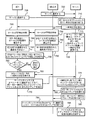
図7に関してより詳細に下に説明するように、本発明の1つまたは複数の実施形態は、P2Pで媒介されるデータ転送が要求されるとき、および表向きはユーザまたはオペレータの観点から、データ転送がP2Pを介して発生するときに、サーバで媒介されるデータ転送の実装に導くものである。言い換えると、P2Pで媒介されるデータ転送は、サーバリダイレクトの態様に関して、送信側またはターゲットのそれぞれのオペレータに通知することなく、サーバに「リダイレクト」され、サーバを介して伝達される。少なくとも1つの実施形態では、サーバリダイレクト機能は、P2Pを介して、またはサーバを介した伝達のためにオペレータのP2Pに特有のデータ転送要求を無効にするように機能する他の基準に基づいて、そうでなければ匿名で実施されるであろうデータ転送を追跡するために、法の執行を許可するために監視(たとえば盗聴)機能を実装するために実装され得る。 As described in more detail below with respect to FIG. 7, one or more embodiments of the present invention provide data transfer when P2P-mediated data transfer is required and from the user or operator's perspective. Leads to the implementation of server-mediated data transfer when occurs over P2P. In other words, the P2P mediated data transfer is “redirected” to the server and communicated through the server without notifying the sender or target operator regarding the server redirection aspect. In at least one embodiment, the server redirection function is based on other criteria that function to override the operator's P2P specific data transfer request via P2P or for transmission via the server, It can be implemented to implement a monitoring (eg, eavesdropping) function to allow law enforcement to track data transfers that would otherwise be performed anonymously.
図7は、本発明の実施形態によるサーバリダイレクトに関連するP2Pで開始されたデータ転送を実装するプロセスを示す図である。図7を参照すると、UE2…Nは、インターネット接続を介して、アプリケーションサーバ170などのサーバに登録する(700)。図7の実施形態では、サーバは、サーバがUE2…Nおよび/またはそれぞれのオペレータに接触することができる、UE2…Nに対する1つまたは複数の一意のユーザアドレスおよび/またはネットワークアドレスを登録する。UE1は、また、オプションとして、700と同じように、705でそれ自体をサーバに登録する。サーバは、UE2…Nおよび(オプションで)UE1に一時的なIDを割り当て(710)、次いで、UE2…Nおよび(オプションで)UE1に一時的なIDを報告する(715)。例では、一時的なIDは、一時的なIDが、P2P接続されたUE間でどのように交換されるかを管理する命令だけでなく、P2Pで開始されるデータ転送が、関連する一時的なIDの指示とともにサーバにリダイレクトされるときにトリガするための命令とともに、715で送られ得る。あるいは、命令は、UE1…Nの1つまたは複数にプリインストールされ得る。UE1…Nに一時的なIDを割り当てた後、サーバは、ネットワークインターフェースを介して関連するUEまたは関連するオペレータに接触され得る、対応する一意のユーザアドレスおよび/または一意のネットワークアドレスに、一時的なIDをマッピングするテーブルを維持(たとえば、生成または更新)する。
FIG. 7 is a diagram illustrating a process for implementing P2P-initiated data transfer related to server redirection according to an embodiment of the present invention. Referring to FIG. 7, UE2... N registers with a server such as
後のある時点で、UE1…Nがそれぞれ、図5に示した所与のP2P通信範囲500に入ると想定する。UE1…Nが所与のP2P通信範囲500内にある間、UE1…Nのそれぞれは、(たとえば、それぞれ図6の600から605と同様に)ローカルP2P検出手順を実行する(725および730)。725および730のローカルのP2P検出手順に基づいて、UE1…Nは相互に検出し、P2P通信が媒介され得る1つまたは複数のローカルP2P接続を形成する(735および740)。たとえば、735および740のローカルP2P検出手順は、UE1を伝えるために、ローカルP2P通信インターフェース505を介して、UE1が識別子(たとえばSSID、割り当てられた一時的なIDなど)をブロードキャストすることを含むことができ、UE2は、ローカルP2P通信インターフェース505を監視することによってUE1のブロードキャストされたSSIDを検出し(または逆)、その後、UE1および2は、ローカルのP2P接続をセットアップする。次いで、このプロセスは、所与のP2P通信範囲500の追加のP2P対応のUEについて繰り返され得る。この時点で、UE1…Nは、ローカルP2P接続を確立済みであるが、UE1…Nが、1つまたは複数の他のUEが信頼された連絡先ではないと決定する可能性がある(745および750)。UE1…Nが1つまたは複数の他のUEを信頼された連絡先と認識しない場合、特定のプライベート情報の交換(たとえばオペレータの一意のユーザアドレスまたは関連するUEの一意のネットワークアドレス情報)は、一般的に、実行前に、それぞれのUEのそれぞれのオペレータによって手作業で承認される必要がある(すなわち、どちらかのUEが信頼していない)。
Assume that at some later time, UE1... N each enter a given
UE1…NがローカルP2P接続を介して接続され続けている間に、UE1のオペレータ(「オペレータ1」)は、UE2…Nおよび/またはUE2…Nのそれぞれのオペレータ(「オペレータ2…N」)にファイルを送り、および/またはメディアをストリーム送信することを決定すると想定する(755)。たとえば、オペレータ1は、UE2…Nにメディアをストリーム送信することを望む場合がある。図6の635とは違い、755では、UE1のオペレータ1は、(たとえば640に似たターゲットインターフェースとしてP2Pを選択することによってなど)ローカルP2P接続を介して、彼/彼女がファイルおよび/またはメディアストリームの転送を実装することを希望することを示していると想定する。
While UE1 ... N continues to be connected via the local P2P connection, the operator of UE1 ("
755でオペレータに要求されたP2P転送の検出に応じて、UE1は、P2P転送を傍受し、サーバにファイルおよび/またはメディアストリームをリダイレクトするべきかどうかを決定する(760)。760の決定は、様々な異なる方法では実行され得る。たとえば、UE1には、(i)UE1によって開始されたすべてのP2P送信(たとえば、法執行機関は、UE1および/またはオペレータ1の電話を盗聴するための令状を持っている)、(ii)指定されたターゲットUE1に向けられたUE1からのP2P送信(たとえば、法執行機関は、指定されたターゲットUEおよび/またはそれらの関連するオペレータの電話を盗聴するための令状を持っている)、(iii)特定のメディアタイプを含むP2P送信(たとえば、オーディオ、ビデオ、暗号化されたデータファイル、著作権で保護されたものなど)、(iv)特定の時刻および/または特定の場所で発生するP2P送信(たとえば法執行機関が盗聴するための令状を持っている家の中)、(v)オペレータ(たとえば、オペレータが後にこのルールについて忘れ、曲をP2P転送することを依頼する場合でも、オペレータは、記録を維持するためにサーバを介して任意の曲が転送されることを望む場合がある)または他の何らかのエンティティ(たとえばIT管理者は、1つまたは複数の企業ユーザによって運用されるデバイスに適用される企業ポリシーの一部としてP2Pオーバーライドルールを確立することができる)によって指定され得るP2Pオーバーライドルールを満たすP2P送信、または(vi)それらの任意の組合せを傍受するように、UE1に指示するサーバリダイレクト命令(たとえば、715で、一時的なIDに関連してダウンロードされたか、または何らかの個別の供給手順を介して)が供給され得る。 In response to detecting the P2P transfer requested by the operator at 755, UE1 intercepts the P2P transfer and determines whether to redirect the file and / or media stream to the server (760). The 760 determinations can be performed in a variety of different ways. For example, for UE1, (i) all P2P transmissions initiated by UE1 (for example, law enforcement has a warrant to eavesdrop on UE1 and / or operator 1's phone), (ii) specified P2P transmission from UE1 destined to the designated target UE1 (e.g., law enforcement has a warrant to eavesdrop on the designated target UE and / or their associated operator's phone), (iii ) P2P transmissions with specific media types (e.g. audio, video, encrypted data files, copyrighted ones, etc.), (iv) P2P transmissions occurring at specific times and / or specific locations (E.g. in a house where law enforcement has a warrant for eavesdropping), (v) an operator (e.g. even if the operator later forgets about this rule and asks the music to be P2P transferred) , You may want to transfer any song through the server to keep records) or some other entity (e.g. an IT administrator on a device operated by one or more corporate users Instruct UE1 to intercept P2P transmissions that meet P2P override rules that can be specified by (which can establish P2P override rules as part of the applicable corporate policy), or (vi) any combination thereof Server redirection instructions (e.g., downloaded at 715 in connection with a temporary ID or via some separate provisioning procedure) may be provided.
760で、UE1がサーバにファイルおよび/またはメディアストリームをリダイレクトしないことを決定した場合、プロセスは図6の670に進み、サーバリダイレクトなしでP2P転送を進めることが許可される。そうでない場合、760で、UE1がサーバにファイルおよび/またはメディアストリームをリダイレクトすることを決定した場合、765で、UE1は、UE2…Nに対する一時的なIDを取得する。765で、UE1は、また、オプションとして、UE2…Nのいずれかにそれ自体の一時的なIDを送ることができる。また、765に示した一時的なID交換は、(たとえば、それぞれのUEを識別するブロードキャストされたSSIDに等しい一時的なIDを設定することによってなど)ローカルP2P接続が735および740で確立された場合、および/または725および730のローカルP2P検出手順の間など、初期の時点で代わりに実装され得る。 If at 760, UE1 decides not to redirect the file and / or media stream to the server, the process proceeds to 670 in FIG. 6 and is allowed to proceed with the P2P transfer without server redirection. Otherwise, if at 760, UE1 decides to redirect the file and / or media stream to the server, at 765, UE1 obtains a temporary ID for UE2 ... N. At 765, UE1 can also optionally send its own temporary ID to any of UE2 ... N. Also, the temporary ID exchange shown in 765 has established a local P2P connection at 735 and 740 (for example, by setting a temporary ID equal to the broadcast SSID identifying each UE) And / or may be implemented instead at an early point in time, such as during 725 and 730 local P2P detection procedures.
図7を参照すると、UE2…Nの一時的なIDを取得した後、UE1は、サーバリダイレクトについてオペレータ1に通知することなく、UE2…Nの一時的なIDとともにサーバにファイルおよび/またはメディアストリームを送信する(770)。言い換えると、オペレータ1は、P2Pで媒介されたデータ転送を要求したが、オペレータ1には知られておらず、データ転送は、サーバで媒介されたデータ転送としてサーバにリダイレクトされる。理解されるように、この偽装(deception)は、ユーザインターフェース(UI)の交換を伴う場合がある(たとえば、UE1の「4G」または「3G」のインジケータがブロックされ得て、代わりに「P2P」識別子が示され得るため、実際には事実ではないが、データ転送がP2Pを介して実際に発生しているかのように、オペレータ1には見える)。サーバは、UE1から受信された一時的なIDに基づいて、一意のネットワークアドレスおよび/または一意のユーザアドレスをルックアップし(775)、次いで、UE2…Nにファイルおよび/またはメディアストリームを伝達する(780)。オプションとして、サーバで媒介されたデータ転送がグループ通信である場合(すなわち、Nは2よりも大きいため、ファイルおよび/またはメディアストリームは、複数のターゲットUEに送られる)、サーバは、UE1…Nに一時的なグループIDを割り当てることができるため、各ターゲットUEの個々の一時的なIDを別々にリストに記載するというニーズなしで、一時的なグループIDを含む、サーバで受信された次のデータ転送は、通信グループとしてUE1…Nにマッピングされる(785)(たとえば、そのため、一時的なグループIDを接続するUE3からのデータ転送は、UE1…NからUEに相互に伝達されるなど)。そのため、サーバ自体は、次に、様々なUEおよび/またはオペレータの一意のユーザアドレスおよび/または一意のネットワークアドレスにマッピングされる、個々の一時的なIDに一時的なグループIDをマッピングすることができる。
Referring to FIG. 7, after obtaining the temporary ID of UE2 ... N, UE1 does not notify
790で、UE2…Nは、それぞれのオペレータにサーバリダイレクトについて通知することなく、サーバからファイルおよび/またはメディアストリームを受信する。たとえば、上に示したオペレータ1の偽装と同様に、UIの交換は、UE2…NでもP2P偽装を促進するために活用され得る(たとえば、UE2…Nの「4G」または「3G」のインジケータがブロックされ得て、代わりに「P2P」識別子が示され得るため、実際には事実ではないが、データ転送がP2Pを介して実際に発生しているかのように、オペレータ2には見える)。
At 790, UE2... N receives files and / or media streams from the server without notifying each operator about server redirection. For example, similar to the
795で、サーバは、ファイルおよび/またはメディアストリームのサーバで媒介された転送の記録を生成する。図7に明示的に示していないが、795で生成された記録は、サーバによって維持されているデータベースにアーカイブまたは記憶され得て、サーバ(またはサーバの管理者)は、後で、記録の1つまたは複数に対してデータ要求を受信することができる。たとえば、適切な令状を持った法執行機関は、UE4に起因するすべてのビデオストリーム、または特定の日付範囲にUE2によって受信されたすべてのテキストメッセージ、またはUE1…Nのいずれかから特定の電子メールアドレスに送られたすべての電子メールなどを要求することができる。他の例では、795で生成された記録は、サーバでローカルに記憶されている記録に加えて、またはその代わりに、個別の監視サーバへ転送され得る。個別の監視サーバへ特定の記録を転送するサーバの決定は、サーバによって実行される1つまたは複数の記録転送ポリシー(record forwarding policy)に基づく場合がある。たとえば、FBIが特定のユーザの通信に関連する盗聴の令状を持っている場合、特定のユーザに関連付けられた記録(たとえば、特定のユーザとの間で送受信されたファイルおよび/またはメディアストリーム)は、リアルタイムにFBIによって運用される監視サーバへ転送され得て、そこで転送された記録は、FBIによって検査に利用可能である。 At 795, the server generates a record of the server-mediated transfer of the file and / or media stream. Although not explicitly shown in FIG. 7, the record generated at 795 can be archived or stored in a database maintained by the server, and the server (or server administrator) can later record one of the records. Data requests can be received for one or more. For example, a law enforcement agency with the appropriate warrant may request that all video streams attributed to UE4, or all text messages received by UE2 for a specific date range, or a specific email from UE1… N You can request all emails sent to the address. In other examples, the records generated at 795 may be transferred to a separate monitoring server in addition to or instead of the records stored locally at the server. The determination of a server to forward a particular record to an individual monitoring server may be based on one or more record forwarding policies implemented by the server. For example, if the FBI has an eavesdropping warrant related to a particular user's communication, records associated with that particular user (for example, files and / or media streams sent to and received from a particular user) Can be transferred in real time to a monitoring server operated by the FBI, where the transferred records are available for inspection by the FBI.
図7は、サーバリダイレクトが、要求されたP2Pで媒介されたデータ転送の代わりに発生する例示的な実装を示している一方、図8は、P2Pで媒介されたデータ転送に加えてサーバリダイレクトが発生する代替実装に導かれるものである。 Figure 7 shows an exemplary implementation where server redirection occurs instead of the requested P2P mediated data transfer, while Figure 8 shows that server redirection is in addition to P2P mediated data transfer. This leads to alternative implementations that occur.
図8を参照すると、765でUE2…Nの一時的なIDを取得した後、UE1は、サーバリダイレクトについてオペレータ1に通知することなく、UE2…Nの一時的なIDとともにサーバにファイルおよび/またはメディアストリームを送信し(800)(たとえば、図7の770に類似する)、サーバは、UE1から受信された一時的なIDに基づいて、一意のネットワークアドレスおよび/または一意のユーザアドレスをルックアップし(805)(たとえば、図7の775に類似する)、サーバで媒介されるデータ転送がグループ通信である場合、サーバは、オプションとして、UE1…Nに一時的なグループIDを割り当てる(810)(たとえば、図7の785に類似する)。図8で、サーバに、図7のようにUE2…Nにファイルおよび/またはメディアストリームを伝達させる代わりに、UE1は、735および740からローカルP2P接続を介してUE2…Nにファイルおよび/またはメディアストリームを送る(815)。この場合、UE1は、P2Pデータ転送自体を回避する代わりに、サーバにもファイルおよび/またはメディアストリームが送られているという事実を単に隠す必要があり、UE2…Nは、800で発生したサーバリダイレクトについて認識することなく、ファイルおよび/またはメディアストリームがP2Pを介して発生したことを単に認識している。この場合、サーバは、805からの一時的なIDルックアップ動作に基づいて、ファイルおよび/またはメディアストリームのサーバで媒介される転送の記録を生成する(820)(たとえば、図7の795に類似する)。795に関して上に示したように、他の例では、820で生成された記録は、サーバにローカルに記憶されている記録に加えて、またはその代わりに、個別の監視サーバへ転送され得る。個別の監視サーバへ特定の記録を転送するというサーバの決定は、サーバによって実行された1つまたは複数の記録転送ポリシーに基づく場合がある。たとえば、FBIが特定のユーザの通信に関連する盗聴の令状を持っている場合、特定のユーザに関連付けられた記録(たとえば、特定のユーザとの間で送受信されたファイルおよび/またはメディアストリーム)は、リアルタイムにFBIによって運用される監視サーバへ転送され得て、そこで転送された記録は、FBIによって検査するために利用可能である。
Referring to FIG. 8, after obtaining the temporary ID of UE2 ... N at 765, UE1 does not notify
図7〜図8は、データ転送のために送信および/または受信するデバイスのオペレータに透過的な方法で発生するサーバリダイレクトの実施形態に関し、本発明の他の実施形態は、サーバリダイレクトに関して必ずしも偽装でないサーバで媒介されるデータ転送に関する。特に、図9〜図10は、UEがP2P接続されていないときでも、それぞれのUEの間で非P2P通信を実装するために、2つ以上のUEに対してP2P接続された通信状態を定義することに導かれる。 FIGS. 7-8 relate to embodiments of server redirection that occur in a manner that is transparent to the operator of the device sending and / or receiving for data transfer, and other embodiments of the present invention are not necessarily impersonating with respect to server redirection. Related to non-server-mediated data transfer. In particular, FIGS. 9 to 10 define a communication state in which P2P connections are made to two or more UEs in order to implement non-P2P communication between each UE even when the UEs are not P2P connected. Led to do.
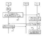
図9に関して、700〜750はすでに実行済みで、その後、UE1…Nは、735および740で確立されたローカルP2P接続を介して接続され続けることを想定する。次に、UE1のオペレータ(「オペレータ1」)は、UE2…Nおよび/またはUE2…Nのそれぞれのオペレータ(「オペレータ2…N」)に、ファイルを送信および/またはメディアをストリーム送信することを決定することを想定する(900)。たとえば、オペレータ1は、UE2…Nにメディアをストリーム送信することを望む場合がある。図7の755とは違い、900で、UE1のオペレータ1は、サーバを介して彼/彼女がファイルおよび/またはメディアストリームの転送を実装することを希望することを示すことを想定する(たとえば640に似たターゲットインターフェースとしてネットワークインターフェースを選択することによってなど)。
With respect to FIG. 9, assume that 700-750 have already been performed, after which UE1... N continues to be connected via the local P2P connection established at 735 and 740. Next, the operator of UE1 ("
900でのオペレータに要求されたサーバで媒介されるデータ転送の検出に応じて、905で、UE1は、UE2…Nに対する一時的なIDを取得する(たとえば、図7の765に類似する)。図7の765と同様に、905で、UE1は、また、オプションとして、UE2…Nのいずれかにそれ自体の一時的なIDを送ることができる。また、905に示した一時的なID交換は、(たとえば、それぞれのUEを識別するブロードキャストされたSSIDに等しい一時的なIDを設定することによってなど)ローカルP2P接続が735および740で確立された場合、および/または725および730のローカルP2P検出手順の間など、初期の時点で代わりに実装され得る。 In response to the server-mediated data transfer detection requested by the operator at 900, UE1 obtains a temporary ID for UE2 ... N at 905 (eg, similar to 765 in FIG. 7). Similar to 765 in FIG. 7, at 905, UE1 can also optionally send its own temporary ID to any of UE2 ... N. Also, the temporary ID exchange shown in 905 indicates that local P2P connections were established at 735 and 740 (for example, by setting a temporary ID equal to the broadcast SSID that identifies each UE) And / or may be implemented instead at an early point in time, such as during 725 and 730 local P2P detection procedures.
図9を参照すると、UE2…Nの一時的なIDを取得した後、UE1は、UE2…Nの一時的なIDとともにサーバにファイルおよび/またはメディアストリームを送信する(910)。910の送信は必ずしも、データ転送のサーバで媒介される実装について、オペレータ1に通知することなく発生する必要はないという点を除いて、図9の910は、図7の770に似ている。サーバは、UE1から受信された一時的なIDに基づいて、一意のネットワークアドレスおよび/または一意のユーザアドレスをルックアップし(915)(たとえば、図7の775に類似する)、次いで、UE2…Nにファイルおよび/またはメディアストリームを伝達する(920)(たとえば、図7の780に類似する)。オプションとして、サーバで媒介されたデータ転送がグループ通信である場合(すなわち、Nは2よりも大きいため、ファイルおよび/またはメディアストリームは、複数のターゲットUEに送られる)、サーバは、UE1…Nに一時的なグループIDを割り当てることができるため、各ターゲットUEの個々の一時的なIDを別々にリストに記載するニーズなく、一時的なグループIDを含む、サーバで受信された次のデータ転送は、通信グループとしてUE1…Nにマッピングされる(925)(たとえば、図7の785に類似する)。そのため、サーバ自体は、次に、様々なUEおよび/またはオペレータの一意のユーザアドレスおよび/または一意のネットワークアドレスにマッピングされる、個々の一時的なIDに一時的なグループIDをマッピングすることができる。
Referring to FIG. 9, after obtaining the temporary ID of UE2... N, UE1 transmits a file and / or media stream to the server along with the temporary ID of UE2. 910 in FIG. 9 is similar to 770 in FIG. 7 except that the transmission of 910 does not necessarily have to occur without notifying
930で、サーバは、ファイルおよび/またはメディアストリームのサーバで媒介される転送の記録を生成する(たとえば、図7の795に類似する)。図7に明示的に示していないが、930で生成された記録は、ローカルまたはリモートのデータベースにアーカイブされ得て、サーバ(またはサーバの管理者)は、後に、記録の1つまたは複数に対するデータ要求を受信することができる。たとえば、盗聴しない場合には、UE1…Nの1つまたは複数は、1つまたは複数のアーカイブされた記録のコピーを要求することができる。 At 930, the server generates a record of the file and / or media stream mediated transfer (eg, similar to 795 of FIG. 7). Although not explicitly shown in FIG. 7, the records generated at 930 can be archived to a local or remote database, and the server (or server administrator) can later provide data for one or more of the records. A request can be received. For example, if not eavesdropping, one or more of UE1 ... N may request a copy of one or more archived records.
後のある時点で、UE1は、所与のP2P通信範囲500内にないため、735で確立されたローカルP2P接続は終了することを想定する(935)(たとえば、Nが2よりも大きい場合でも、UE2と3の間など、740で確立された個別のローカルP2P接続が維持され得るなど)。サーバは、P2P切断の後にも、930から、一時的なIDとUE2…N、および/または一時的なグループIDとUE1…Nの間の関連付けを維持することを想定する。次に、UE1のオペレータ1は、UE2…Nおよび/またはUE2…Nのそれぞれのオペレータ(「オペレータ2…N」)に、追加のファイルを送信および/または追加のメディアをストリーム送信することを決定する(940)。この時点で、UE1からUE2…Nへの追加のファイルおよび/またはメディアストリームのP2P転送は可能ではない。それによって、P2P転送を試みる代わりに、UE1は、(i)905で取得されたUE2…Nの一時的なID、または(ii)925でオプションで取得された一時的なグループIDとともにサーバに追加のファイルおよび/またはメディアストリームを送信する(945)。他の例では、図9に示すようにオペレータ1がUE1を制御している場合、またはあるいはオペレータ1が例に示した他の何らかのUEを制御している間に、940の決定が発生する場合がある。たとえば、UE1は、900〜925の間にUE2…Nのオペレータとの会議の間に、オペレータ1によって運用されるタブレットPCに対応することができる。その後、オペレータ1は、異なるUE(たとえば携帯電話)を運用しており、940で決定されたデータを送ることを希望する。この場合、940〜945は、タブレットPCの代わりに携帯電話を介して実行され得るため、上記のプロセスの異なる部分を実行するUEは、少なくとも1つの実施形態のそれぞれのプロセスの全体にわたって同じ状態を維持する必要はない。
At some later time, assume that UE1 is not within the given
サーバは、UE1から受信された一時的なID(または一時的なグループID)に基づいて、一意のネットワークアドレスおよび/または一意のユーザアドレスをルックアップし(950)、次いで、UE2…Nおよび/またはそれぞれのオペレータに追加のファイルおよび/またはメディアストリームを伝達する(955)。言い換えると、955の伝達は、実際には、UE2…Nに直接的に伝達される必要はないが、これは確かに可能である。たとえば、オペレータ2が、その一時的なIDに関連してサーバによって維持される一意のユーザアドレス(たとえば電子メールアドレスまたはSkypeユーザ名)を持っている場合、サーバは、電子メールアドレスまたはSkypeユーザ名に、追加のファイルおよび/またはメディアストリームを転送することができ、オペレータ2が、異なるUEを運用している場合(たとえばUE X)、次いで、オペレータ2は、実際に、UE2の代わりにUE Xの追加のファイルおよび/またはメディアストリームを受信することができる。960で、サーバは、追加のファイルおよび/またはメディアストリームのサーバで媒介される転送の記録を生成する(たとえば、930に類似する)。図7の795および図8の820に関して上に示したように、他の例では、930および/または960で生成された記録は、サーバでローカルに記憶されている記録に加えて、またはその代わりに、個別の監視サーバへ転送され得る。個別の監視サーバへ特定の記録を転送するというサーバの決定は、サーバによって実行された1つまたは複数の記録転送ポリシーに基づく場合がある。たとえば、FBIが特定のユーザの通信に関連する盗聴の令状を持っている場合、特定のユーザに関連付けられた記録(たとえば、特定のユーザとの間で送受信されたファイルおよび/またはメディアストリーム)は、リアルタイムにFBIによって運用される監視サーバへ転送することができ、そこで転送された記録は、FBIによって検査するために利用可能である。図9の935と960との間に発生するサーバで媒介されるデータ転送は、UE2…N(または一時的なグループID)の一時的なIDと、オペレータ2…Nのそれぞれの一意のユーザアドレスおよび/またはUE1がUE2…NとのP2P範囲外になった後のUE2…Nのネットワークアドレスとの間の記憶されたマッピングに基づいている。しかしながら、図10に示すように、サーバで媒介されるデータ転送は、また、UE1に戻るように向けられ得る。
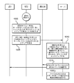
The server looks up the unique network address and / or unique user address based on the temporary ID (or temporary group ID) received from UE1, (950), and then UE2 ... N and / or Alternatively, additional files and / or media streams are communicated to each operator (955). In other words, the transmission of 955 does not actually have to be transmitted directly to UE2 ... N, but this is certainly possible. For example, if
図10を参照すると、Nは2よりも大きいため、UE1…Nは、少なくともUE3を含むと想定する。図9の960の後、UE1は、すでに所与のP2P通信範囲500内にないため、735で確立されたローカルP2P接続は終了するが、オペレータ2は、UE1および3…Nおよび/またはUE2…Nのそれぞれのオペレータ(「オペレータ1および3…N」)に、ファイルを送信および/または追加のメディアをストリーム送信することを決定することを想定する(1000)。この時点で、UE2からUE1への追加のファイルおよび/またはメディアストリームのP2P転送は可能ではない(ただし、理論上は、UE2は、状況に依存してUE3…NとのローカルP2P接続を保持することができる)。それによって、P2P転送を試みる代わりに、UE2は、(i)905で取得されたUE1および3…Nの一時的なID、または(ii)925でオプションで取得された一時的なグループIDとともにサーバにファイルおよび/またはメディアストリームを送信する(1005)。他の例では、図10に示すようにオペレータ2がUE2を制御している場合、または代わりに、オペレータ2が例に示した他の何らかのUEを制御している間に、1000の送信が発生する場合がある。たとえば、UE2は、900〜925の間にUE1および3…Nのオペレータとの会議の間に、オペレータ2によって運用されるタブレットPCに対応することができる。その後、オペレータ2は、異なるUE(たとえば携帯電話)を運用しており、1000で決定されたデータを送ることを希望する。この場合、1000〜1005は、タブレットPCの代わりに携帯電話を介して実行され得るため、上記のプロセスの異なる部分を実行するUEは、少なくとも一実施形態のそれぞれのプロセスの全体にわたって同じ状態を維持する必要はない。
Referring to FIG. 10, since N is greater than 2, it is assumed that UE1 ... N includes at least UE3. After 960 in FIG. 9, UE1 is not already in the given
サーバは、UE2から受信された一時的なID(または一時的なグループID)に基づいて、一意のネットワークアドレスおよび/または一意のユーザアドレスをルックアップし(1010)、次いで、UE1および3…Nおよび/またはそれぞれのオペレータに追加のファイルおよび/またはメディアストリームを伝達する(1015)。言い換えると、1015の伝達は、実際には、UE1および3…Nに直接的に伝達される必要はないが、これは確かに可能である。たとえば、オペレータ3が、その一時的なIDに関連してサーバによって維持される一意のユーザアドレス(たとえば電子メールアドレスまたはSkypeユーザ名)を持っている場合、サーバは、電子メールアドレスまたはSkypeユーザ名に、追加のファイルおよび/またはメディアストリームを転送することができ、オペレータ3が異なるUE(たとえばUE X)を運用している場合、オペレータ3は、実際に、UE3の代わりにUE Xの追加のファイルおよび/またはメディアストリームを受信することができる。1020で、サーバは、追加のファイルおよび/またはメディアストリームのサーバで媒介される転送の記録を記憶する(たとえば、960に類似する)。図7の795、図8の820、図9の930、および図9の960に関して上に示したように、他の例では、1020で生成された記録は、サーバにローカルに記憶されている記録に加えて、またはその代わりに、個別の監視サーバへ転送され得る。個別の監視サーバへ特定の記録を転送するというサーバの決定は、サーバによって実行された1つまたは複数の記録転送ポリシーに基づく場合がある。たとえば、FBIが特定のユーザの通信に関連する盗聴の令状を持っている場合、特定のユーザに関連付けられた記録(たとえば、特定のユーザとの間で送受信されたファイルおよび/またはメディアストリーム)は、リアルタイムにFBIによって運用される監視サーバへ転送することができ、そこ転送された記録は、FBIによって検査するために利用可能である。
The server looks up the unique network address and / or unique user address based on the temporary ID (or temporary group ID) received from UE2 (1010), and then UE1 and 3 ... N And / or communicate additional files and / or media streams to the respective operators (1015). In other words, the transmission of 1015 does not actually have to be transmitted directly to UE1 and 3 ... N, but this is certainly possible. For example, if
情報および信号は、様々な異なる技術および手法のいずれかを使用して表していることを当業者は理解されるであろう。たとえば、上の記述の全体にわたって使われているデータ、命令、コマンド、情報、信号、ビット、シンボル、およびチップは、電圧、電流、電磁波、磁界もしくは電磁粒子、光学的フィールドもしくは光学的粒子、またはそれらの任意の組合せによって表すことができる。 Those of skill in the art will understand that information and signals may be represented using any of a variety of different technologies and techniques. For example, data, instructions, commands, information, signals, bits, symbols, and chips used throughout the above description are voltages, currents, electromagnetic waves, magnetic fields or electromagnetic particles, optical fields or optical particles, or It can be represented by any combination thereof.
さらに、本明細書に開示した実施形態に関して記述した様々な実例となる論理ブロック、モジュール、回路、およびアルゴリズムステップは、電子ハードウェア、コンピュータソフトウェア、または両方の組合せとして実装できることを当業者なら自明であろう。ハードウェアおよびソフトウェアのこの互換性を明白に示すために、様々な実例となるコンポーネント、ブロック、モジュール、回路、およびステップを、それらの機能の点から一般的に記述した。そのような機能をハードウェアとして実装するかソフトウェアとして実装するかは、全体的なシステムに課された特定の用途および設計制約に依存している。熟練者であれば、特定の各用途に対して様々な方法で記述した機能を実装することができるが、そのような実装の決定は、本発明の範囲から逸脱するものとして解釈するべきでない。 Further, those skilled in the art will appreciate that the various illustrative logic blocks, modules, circuits, and algorithm steps described with respect to the embodiments disclosed herein can be implemented as electronic hardware, computer software, or a combination of both. I will. To clearly illustrate this interchangeability of hardware and software, various illustrative components, blocks, modules, circuits, and steps have been described generically in terms of their functionality. Whether such functionality is implemented as hardware or software depends upon the particular application and design constraints imposed on the overall system. Those skilled in the art can implement the functions described in various ways for each particular application, but such implementation decisions should not be construed as departing from the scope of the invention.
本明細書に開示した実施形態に関して記述した様々な説明の論理ブロック、モジュール、および回路は、汎用プロセッサ、デジタル信号プロセッサ(DSP)、特定用途向け集積回路(ASIC)、フィールドプログラマブルゲートアレイ(FPGA)もしくは他のプログラマブルロジックデバイス、個別のゲートもしくはトランジスタロジック、個別のハードウェアコンポーネント、または本明細書に記述した機能を実行するために設計されたそれらの任意の組合せで実装または実行することができる。汎用プロセッサは、マイクロプロセッサでもよいが、代替案では、プロセッサは、任意の従来のプロセッサ、コントローラ、マイクロコントローラ、またはステートマシンでもよい。また、プロセッサは、たとえば、DSPおよびマイクロプロセッサ、複数のマイクロプロセッサ、DSPコアに関連する1つまたは複数のマイクロプロセッサ、または他のそのような構成の組合せなど、コンピューティングデバイスの組合せとして実装することができる。 Various illustrative logic blocks, modules, and circuits described with respect to the embodiments disclosed herein include general purpose processors, digital signal processors (DSPs), application specific integrated circuits (ASICs), field programmable gate arrays (FPGAs). Alternatively, it may be implemented or implemented with other programmable logic devices, individual gate or transistor logic, individual hardware components, or any combination thereof designed to perform the functions described herein. A general purpose processor may be a microprocessor, but in the alternative, the processor may be any conventional processor, controller, microcontroller, or state machine. A processor may also be implemented as a combination of computing devices such as, for example, a DSP and a microprocessor, a plurality of microprocessors, one or more microprocessors associated with a DSP core, or any other combination of such configurations. Can do.
本明細書に開示した実施形態に関して記述した方法、順序、および/またはアルゴリズムは、ハードウェア、プロセッサによって実行されるソフトウェアモジュール、または2つの組合せで直接的に具体化することができる。ソフトウェアモジュールは、RAMメモリ、フラッシュメモリ、ROMメモリ、EPROMメモリ、EEPROMメモリ、レジスタ、ハードディスク、リムーバブルディスク、CD-ROM、または当技術分野で既知の記憶媒体の他の形態に存在することができる。代表的な記憶媒体は、プロセッサが記憶媒体から情報を読み出し、かつ情報を書き込めるようにプロセッサに結合される。代替案では、記憶媒体はプロセッサと一体型でもよい。プロセッサおよび記憶媒体はASICに存在することができる。ASICは、ユーザ端末(たとえばUE)に存在することができる。代替案では、プロセッサおよび記憶媒体は、ユーザ端末の個別の構成要素として存在することができる。 The methods, sequences, and / or algorithms described with respect to the embodiments disclosed herein can be directly embodied in hardware, software modules executed by a processor, or a combination of the two. A software module may reside in RAM memory, flash memory, ROM memory, EPROM memory, EEPROM memory, registers, hard disk, removable disk, CD-ROM, or other form of storage medium known in the art. An exemplary storage medium is coupled to the processor such that the processor can read information from, and write information to, the storage medium. In the alternative, the storage medium may be integral to the processor. The processor and the storage medium can reside in an ASIC. The ASIC can reside in a user terminal (eg, UE). In the alternative, the processor and the storage medium may reside as discrete components in a user terminal.
1つまたは複数の代表的な実施形態では、記述された機能は、ハードウェア、ソフトウェア、ファームウェア、またはそれらの任意の組合せにおいて実装することができる。ソフトウェアに実装した場合、機能は、1つまたは複数の命令またはコードとしてコンピュータ可読媒体に格納するか、またはそこに送信することができる。コンピュータ可読媒体は、ある場所から別の場所へのコンピュータプログラムの転送を円滑にする任意の媒体を含むコンピュータ記憶媒体と通信媒体の両方を含む。記憶媒体は、コンピュータによってアクセスできる任意の利用可能な媒体でもよい。限定を目的とせずに例を挙げると、そのようなコンピュータ可読媒体は、RAM、ROM、EEPROM、CD-ROMもしくは他の光学ディスク記憶装置、磁気ディスク記憶装置もしくは他の磁気記憶装置、または命令またはデータ構造の形で望まれるプログラムコードを運ぶか格納するために使用でき、コンピュータによってアクセスできる他の媒体を含むことができる。また、どのような接続も正しくはコンピュータ可読媒体と呼ばれる。たとえば、同軸ケーブル、光ファイバケーブル、ツイストペア、デジタル加入者線(DSL)、または赤外線、無線、およびマイクロ波などの無線技術を使用して、ソフトウェアがウェブサイト、サーバ、または他の遠隔ソースから伝送される場合、同軸ケーブル、光ファイバケーブル、ツイストペア、DSL、または赤外線、無線、およびマイクロ波など無線技術は、媒体の定義に含まれる。本明細書に使用する場合、ディスク(disk)およびディスク(disc)は、コンパクトディスク(CD)、レーザーディスク(登録商標)、光ディスク、デジタルバーサタイルディスク(DVD)、フロッピー(登録商標)ディスク、およびブルーレイディスクを含み、ディスク(disk)は通常、磁気的にデータを再生する一方、ディスク(disc)は、レーザーを用いてデータを光学的に再生する。上記の組合せも、コンピュータ可読媒体の範囲内に含まれている。 In one or more exemplary embodiments, the functions described can be implemented in hardware, software, firmware, or any combination thereof. If implemented in software, the functions may be stored on or transmitted over as one or more instructions or code on a computer-readable medium. Computer-readable media includes both computer storage media and communication media including any medium that facilitates transfer of a computer program from one place to another. A storage media may be any available media that can be accessed by a computer. By way of example, and not limitation, such computer-readable media may be RAM, ROM, EEPROM, CD-ROM or other optical disk storage, magnetic disk storage or other magnetic storage, or instructions or Other media that can be used to carry or store the desired program code in the form of a data structure and that can be accessed by a computer can be included. Also, any connection is correctly called a computer readable medium. For example, software can be transmitted from a website, server, or other remote source using coaxial cable, fiber optic cable, twisted pair, digital subscriber line (DSL), or wireless technology such as infrared, wireless, and microwave If so, wireless technologies such as coaxial cable, fiber optic cable, twisted pair, DSL, or infrared, wireless, and microwave are included in the definition of the medium. As used herein, a disk and a disc are a compact disc (CD), a laser disc (registered trademark), an optical disc, a digital versatile disc (DVD), a floppy (registered trademark) disc, and a Blu-ray disc. Including a disk, the disk normally reproduces data magnetically, while the disk optically reproduces data using a laser. Combinations of the above are also included within the scope of computer-readable media.
前述の開示は、本発明の説明的な実施形態を示していているが、添付された請求項によって規定される本発明の範囲から逸脱することなく、本明細書において様々な変更および修正が可能であることに注意されたい。本明細書に記述した本発明の実施形態による方法の請求項の機能、ステップ、および/または動作は、特定の順序で実行する必要はない。さらに、本発明の要素は、単数形で記述または請求されている場合があるが、単数に制限することが明示的に述べられていない限り、複数が意図されるものである。 While the foregoing disclosure shows illustrative embodiments of the present invention, various changes and modifications can be made herein without departing from the scope of the invention as defined by the appended claims. Please note that. The functions, steps and / or actions of the method claims described herein according to embodiments of the invention need not be performed in any particular order. Furthermore, although elements of the invention may be described or claimed in the singular, the plural is intended unless expressly stated to be limited to the singular.
100 ワイヤレス通信システム
104 エアインターフェース
106 エアインターフェース
108 エアインターフェース
120 RAN
125 アクセスポイント(AP)
140 コアネットワーク
170 アプリケーションサーバ
175 インターネット
200A UE
200B UE
202 プラットフォーム
205A アンテナ
205B タッチスクリーンディスプレイ
206 送受信装置
208 特定用途向け集積回路(ASIC)
210 アプリケーションプログラミングインターフェース(API)
210A ディスプレイ
210B 周辺のボタン
212 メモリ
214 ローカルデータベース
215A ボタン
215B 周辺のボタン
220A キーパッド
220B 周辺のボタン
225B 周辺のボタン
230B フロントパネルボタン
300 通信デバイス
304 ネットワークアクセスポイント
305 情報を受信および/または送信するように構成されたロジック
310 情報を処理するように構成されたロジック
315 情報を格納するように構成されたロジック
320 情報を提示するように構成されたロジック
325 ローカルユーザ入力を受信するように構成されたロジック
400 サーバ
401 プロセッサ
402 揮発性メモリ
403 ディスクドライブ
404 ネットワークアクセスポート
406 ディスクドライブ
407 ネットワーク
500 P2P通信範囲
505 インターフェース
505 ローカルP2P通信インターフェース
510 第1のネットワーク通信インターフェース
515 第2のネットワーク通信インターフェース
520 基地局
100 wireless communication system
104 Air interface
106 Air interface
108 Air interface
120 RAN
125 Access point (AP)
140 core network
170 Application server
175 Internet
200A UE
200B UE
202 platform
205A antenna
205B touch screen display
206 Transceiver
208 Application Specific Integrated Circuit (ASIC)
210 Application Programming Interface (API)
210A display
Buttons around 210B
212 memory
214 Local database
215A button
Buttons around 215B
220A keypad
Buttons around 220B
225B peripheral buttons
230B Front panel button
300 communication devices
304 Network access point
305 Logic configured to receive and / or send information
310 Logic configured to process information
315 Logic configured to store information
320 Logic configured to present information
325 Logic configured to receive local user input
400 servers
401 processor
402 volatile memory
403 disk drive
404 network access port
406 disk drive
407 network
500 P2P communication range
505 interface
505 Local P2P communication interface
510 First network communication interface
515 Second network communication interface
520 base station
Claims (30)
前記サービスを提供しているネットワークに依存しないローカルのピアツーピア(P2P)インターフェースを介して、前記第1のクライアントデバイスが通信することができる第2のクライアントデバイスを検出するステップと、
前記ローカルP2Pインターフェースを介して、前記第1のクライアントデバイスと前記第2のクライアントデバイスとの間にローカルP2P接続を確立するステップと、
前記ローカルP2P接続を通じて、前記第2のクライアントデバイスに対する一時的な識別子を受信するステップであって、前記一時的な識別子は、前記第1のクライアントデバイスが、前記サービスを提供しているネットワークを介して前記第2のクライアントデバイスに接触され得る一意のネットワークアドレスを識別するのに不十分である、ステップと、
前記第1のクライアントデバイスのオペレータから、前記ローカルP2P接続を通じて前記第2のクライアントデバイスにデータを送信するための要求を受信するステップと、
前記ローカルP2P接続が前記第1のクライアントデバイスと前記第2のクライアントデバイスとの間の通信に利用可能な状態を維持している間に前記要求に応じて、前記データがサーバに送られていることを前記第1のクライアントデバイスの前記オペレータに通知することなく、前記一時的な識別子の指示とともに、前記サービスを提供しているネットワークを介して前記サーバに前記データを送信するステップと
を含む方法。 A method of operating a first client device configured to connect to a network providing a service, comprising:
Detecting a second client device with which the first client device can communicate via a local peer-to-peer (P2P) interface independent of the serving network;
Establishing a local P2P connection between the first client device and the second client device via the local P2P interface;
Receiving a temporary identifier for the second client device through the local P2P connection, wherein the temporary identifier is received via a network in which the first client device provides the service. Insufficient to identify a unique network address that can be contacted with the second client device; and
Receiving a request from an operator of the first client device to send data to the second client device over the local P2P connection;
In response to the request, the data is being sent to a server while the local P2P connection remains available for communication between the first client device and the second client device. Transmitting the data to the server via the network providing the service, together with an indication of the temporary identifier, without notifying the operator of the first client device .
をさらに含む請求項3に記載の方法。 The method of claim 3, further comprising configuring a user interface (UI) that falsely indicates that the data is sent to the server via the local P2P connection instead of the network providing the service. the method of.
をさらに含み、前記サーバに前記データを送信するステップは、前記分析に応じて発生する請求項1に記載の方法。 Analyzing the request to determine whether to perform a server redirect of the data to the server based on a set of server redirect instructions, the step of transmitting the data to the server; The method of claim 1, which occurs in response to the analysis.
サービスを提供しているネットワークを介して第1のクライアントデバイスに接触され得る一意のネットワークアドレスを登録するステップと、
前記第1のクライアントデバイスに、他のクライアントデバイスが前記登録された一意のネットワークアドレスを識別するのに不十分である一時的な識別子を割り当てるステップと、
前記第1のクライアントデバイスおよび第2のクライアントデバイスがローカルのピアツーピア(P2P)接続を介して接続されている間に、前記第2のクライアントデバイスから、前記一時的な識別子の指示とともに前記第1のクライアントデバイスに送信されるデータを受信するステップと、
前記登録された一意のネットワークアドレスに前記一時的な識別子の指示を関連付けるステップと、
前記関連付けに基づいて、前記第1のクライアントデバイスと前記第2のクライアントデバイスとの間の前記データ送信の記録を生成するステップと
を含む方法。 A method of operating a server,
Registering a unique network address that can be contacted by the first client device via the serving network;
Assigning to the first client device a temporary identifier that is not sufficient for other client devices to identify the registered unique network address;
While the first client device and the second client device are connected via a local peer-to-peer (P2P) connection, the first client device with the temporary identifier indication from the second client device. Receiving data sent to the client device;
Associating the temporary identifier indication with the registered unique network address;
Generating a record of the data transmission between the first client device and the second client device based on the association.
をさらに含む請求項10に記載の方法。 Transferring the data to the first client device based on an expectation that the data transmission will not occur via the local P2P connection between the first client device and the second client device. The method of claim 10, further comprising:
をさらに含む請求項10に記載の方法。 11. The method of claim 10, further comprising storing the record locally in memory maintained by the server.
をさらに含む請求項10に記載の方法。 11. The method of claim 10, further comprising the step of transferring the record to at least one external server based on one or more record transfer policies.
請求項10に記載の方法。 The method of claim 10, wherein the data corresponds to one or more files and / or one or more real-time media streams.
(i)サービスを提供しているネットワークを介して第1のクライアントデバイスに接触され得る、または(ii)前記第1のクライアントデバイスのオペレータに接触され得る一意の連絡先アドレスを登録するステップと、
前記第1のクライアントデバイスに、他のクライアントデバイスが前記登録された一意の連絡先アドレスを識別するのに不十分である一時的な識別子を割り当てるステップと、
前記第1のクライアントデバイスおよび第2のクライアントデバイスがローカルのピアツーピア(P2P)接続を介して接続されている間に、前記第2のクライアントデバイスから、前記一時的な識別子の指示とともに前記第1のクライアントデバイスおよび/または前記第1のクライアントデバイスのオペレータに送信されるデータに対する要求を受信するステップと、
前記第1および第2のクライアントデバイスが前記ローカルP2P接続を介して接続されている間に、前記登録された一意の連絡先アドレスを使用して、前記第1のクライアントデバイスおよび/または前記第1のクライアントデバイスの前記オペレータに前記データを伝達するステップと、
(i)前記第2のクライアントデバイスおよび/または前記第2のクライアントデバイスのオペレータと、(ii)前記第1のクライアントデバイスおよび/または前記第1のクライアントデバイスのオペレータとの間で補助的な通信を許可するために、前記第1および第2のクライアントデバイスが前記ローカルのP2P接続から切断された後、前記一時的な識別子と前記第1のクライアントデバイスとの間の関連付けを維持するステップと
を含む方法。 A method of operating a server,
(i) registering a unique contact address that can be contacted by a first client device via a network that provides services, or (ii) that can be contacted by an operator of said first client device;
Assigning to the first client device a temporary identifier that is not sufficient for other client devices to identify the registered unique contact address;
While the first client device and the second client device are connected via a local peer-to-peer (P2P) connection, the first client device with the temporary identifier indication from the second client device. Receiving a request for data sent to a client device and / or an operator of said first client device;
While the first and second client devices are connected via the local P2P connection, using the registered unique contact address, the first client device and / or the first Communicating the data to the operator of the client device of:
(i) auxiliary communication between the second client device and / or the operator of the second client device and (ii) the operator of the first client device and / or the first client device Maintaining an association between the temporary identifier and the first client device after the first and second client devices have been disconnected from the local P2P connection. Including methods.
前記第1および第2のクライアントデバイスが、前記ローカルP2P接続から切断されている間に、前記登録された一意の連絡先アドレスを使用して、前記第1のクライアントデバイスおよび/または前記第1のクライアントデバイスの前記オペレータに前記補助的なデータを伝達するステップと
をさらに含む請求項16に記載の方法。 Sent from a given device operated by the operator of the second client device to the first client device and / or the operator of the first client device along with another indication of the temporary identifier Receiving an auxiliary request for auxiliary data to be performed;
While the first and second client devices are disconnected from the local P2P connection, using the registered unique contact address, the first client device and / or the first client device 17. The method of claim 16, further comprising communicating the auxiliary data to the operator of a client device.
前記データおよび前記補助的なデータは、前記第1のクライアントデバイスおよび/または前記第1のクライアントデバイスの前記オペレータに加えて、1つまたは複数の追加のクライアントデバイスおよび/またはクライアントデバイスオペレータに伝達される
請求項17に記載の方法。 The temporary identifier is a temporary group identifier configured to be mapped to a plurality of different client devices and / or operator unique contact addresses;
The data and the auxiliary data are communicated to one or more additional client devices and / or client device operators in addition to the first client device and / or the operator of the first client device. 18. The method according to claim 17.
請求項16に記載の方法。 The maintaining step may be contacted with the second client device via the serving network and / or another unique contact that may be contacted with the operator of the second client device. The method of claim 16, further maintaining an address.
前記第1および第2のクライアントデバイスが、前記ローカルP2P接続から切断されている間に、前記別の一意の連絡先アドレスを使用して、前記第2のクライアントデバイスおよび/または前記第2のクライアントデバイスの前記オペレータに前記補助的なデータを伝達するステップと
をさらに含む請求項20に記載の方法。 Sent from a given device operated by the operator of the first client device to the second client device and / or the operator of the second client device along with another indication of the temporary identifier Receiving an auxiliary request for auxiliary data to be performed;
While the first and second client devices are disconnected from the local P2P connection, using the other unique contact address, the second client device and / or the second client 21. The method of claim 20, further comprising communicating the auxiliary data to the operator of a device.
前記データおよび前記補助的なデータは、前記第2のクライアントデバイスおよび/または前記第2のクライアントデバイスの前記オペレータに加えて、1つまたは複数の追加のクライアントデバイスおよび/またはクライアントデバイスオペレータに伝達される
請求項21に記載の方法。 The temporary identifier is a temporary group identifier configured to be mapped to a plurality of different client devices and / or operator unique contact addresses;
The data and the auxiliary data are communicated to one or more additional client devices and / or client device operators in addition to the second client device and / or the operator of the second client device. The method according to claim 21.
前記第1のクライアントデバイスに、他のクライアントデバイスが前記登録された一意の連絡先アドレスを識別するのに不十分である一時的な識別子を割り当てるように構成された論理手段と、
前記第1のクライアントデバイスおよび第2のクライアントデバイスがローカルのピアツーピア(P2P)接続を介して接続されている間に、前記第2のクライアントデバイスから、前記一時的な識別子の指示とともに前記第1のクライアントデバイスおよび/または前記第1のクライアントデバイスの前記オペレータに送信されるデータに対する要求を受信するように構成された論理手段と、
前記第1および第2のクライアントデバイスが前記ローカルP2P接続を介して接続されている間に、前記登録された一意の連絡先アドレスを使用して、前記第1のクライアントデバイスおよび/または前記第1のクライアントデバイスの前記オペレータに前記データを伝達するように構成された論理手段と、
(i)前記第2のクライアントデバイスおよび/または前記第2のクライアントデバイスのオペレータと、(ii)前記第1のクライアントデバイスおよび/または前記第1のクライアントデバイスの前記オペレータとの間で補助的な通信を許可するために、前記第1および第2のクライアントデバイスが前記ローカルのP2P接続から切断された後、前記一時的な識別子と前記第1のクライアントデバイスとの間の関連付けを維持するように構成された論理手段と
を含むサーバ。 (i) configured to register a unique contact address that may be contacted by a first client device via a network that provides service, or (ii) that may be contacted by an operator of said first client device Logical means,
Logical means configured to assign a temporary identifier to the first client device that is insufficient for other client devices to identify the registered unique contact address;
While the first client device and the second client device are connected via a local peer-to-peer (P2P) connection, the first client device with the temporary identifier indication from the second client device. Logical means configured to receive a request for data sent to the operator of the client device and / or the first client device;
While the first and second client devices are connected via the local P2P connection, using the registered unique contact address, the first client device and / or the first Logic means configured to communicate the data to the operator of the client device of:
(i) auxiliary between the second client device and / or the operator of the second client device and (ii) the operator of the first client device and / or the first client device To maintain an association between the temporary identifier and the first client device after the first and second client devices are disconnected from the local P2P connection to allow communication. A server including configured logic means.
前記第1および第2のクライアントデバイスが、前記ローカルP2P接続から切断されている間に、前記登録された一意の連絡先アドレスを使用して、前記第1のクライアントデバイスおよび/または前記第1のクライアントデバイスの前記オペレータに前記補助的なデータを伝達することと
をさらに含む請求項24に記載のサーバ。 Sent from a given device operated by the operator of the second client device to the first client device and / or the operator of the first client device along with another indication of the temporary identifier Receiving an auxiliary request for auxiliary data to be performed;
While the first and second client devices are disconnected from the local P2P connection, using the registered unique contact address, the first client device and / or the first client device 25. The server of claim 24, further comprising communicating the auxiliary data to the operator of a client device.
前記データおよび前記補助的なデータは、前記第1のクライアントデバイスおよび/または前記第1のクライアントデバイスの前記オペレータに加えて、1つまたは複数の追加のクライアントデバイスおよび/またはクライアントデバイスオペレータに伝達される
請求項25に記載のサーバ。 The temporary identifier is a temporary group identifier configured to be mapped to a plurality of different client devices and / or operator unique contact addresses;
The data and the auxiliary data are communicated to one or more additional client devices and / or client device operators in addition to the first client device and / or the operator of the first client device. The server according to claim 25.
請求項24に記載のサーバ。 The maintaining may be contacted with the second client device via the serving network and / or another unique contact that may be contacted with the operator of the second client device 25. The server of claim 24, further maintaining an address.
前記第1および第2のクライアントデバイスが、前記ローカルP2P接続から切断されている間に、前記別の一意の連絡先アドレスを使用して、前記第2のクライアントデバイスおよび/または前記第2のクライアントデバイスの前記オペレータに前記補助的なデータを伝達することと
をさらに含む請求項27に記載のサーバ。 Sent from a given device operated by the operator of the first client device to the second client device and / or the operator of the second client device along with another indication of the temporary identifier Receiving an auxiliary request for auxiliary data to be performed;
While the first and second client devices are disconnected from the local P2P connection, using the other unique contact address, the second client device and / or the second client 28. The server of claim 27, further comprising communicating the auxiliary data to the operator of a device.
前記データおよび前記補助的なデータは、前記第2のクライアントデバイスおよび/または前記第2のクライアントデバイスの前記オペレータに加えて、1つまたは複数の追加のクライアントデバイスおよび/またはクライアントデバイスオペレータに伝達される
請求項28に記載のサーバ。 The temporary identifier is a temporary group identifier configured to be mapped to a plurality of different client devices and / or operator unique contact addresses;
The data and the auxiliary data are communicated to one or more additional client devices and / or client device operators in addition to the second client device and / or the operator of the second client device. The server according to claim 28.
Applications Claiming Priority (3)
| Application Number | Priority Date | Filing Date | Title |
|---|---|---|---|
| US14/251,265 | 2014-04-11 | ||
| US14/251,265 US9392057B2 (en) | 2014-04-11 | 2014-04-11 | Selectively exchanging data between P2P-capable client devices via a server |
| PCT/US2015/020594 WO2015156958A1 (en) | 2014-04-11 | 2015-03-13 | Selectively exchanging data between p2p-capable client devices via a server |
Publications (2)
| Publication Number | Publication Date |
|---|---|
| JP2017516201A true JP2017516201A (en) | 2017-06-15 |
| JP2017516201A5 JP2017516201A5 (en) | 2018-04-05 |
Family
ID=52875243
Family Applications (1)
| Application Number | Title | Priority Date | Filing Date |
|---|---|---|---|
| JP2016560984A Ceased JP2017516201A (en) | 2014-04-11 | 2015-03-13 | Selective exchange of data between P2P compatible client devices via a server |
Country Status (7)
| Country | Link |
|---|---|
| US (1) | US9392057B2 (en) |
| EP (1) | EP3130124B1 (en) |
| JP (1) | JP2017516201A (en) |
| KR (1) | KR20160142854A (en) |
| CN (1) | CN106134162A (en) |
| BR (1) | BR112016023657A2 (en) |
| WO (1) | WO2015156958A1 (en) |
Cited By (1)
| Publication number | Priority date | Publication date | Assignee | Title |
|---|---|---|---|---|
| US11582314B1 (en) * | 2021-11-29 | 2023-02-14 | Industrial Technology Research Institute | Method for assisting unregistered user device to access private network service and communication system |
Families Citing this family (6)
| Publication number | Priority date | Publication date | Assignee | Title |
|---|---|---|---|---|
| US10034161B2 (en) * | 2016-03-17 | 2018-07-24 | Karan Singh Bakshi | System and method for providing internet connectivity to radio frequency devices without internet facility through smart devices |
| CN106302661B (en) * | 2016-08-02 | 2019-08-13 | 网宿科技股份有限公司 | P2P data accelerated method, device and system |
| US10834170B2 (en) * | 2018-03-19 | 2020-11-10 | Citrix Systems, Inc. | Cloud authenticated offline file sharing |
| US11489686B2 (en) | 2020-01-14 | 2022-11-01 | Citrix Systems, Inc. | Virtual meetings in ad-hoc networks |
| CN114531446B (en) * | 2020-10-31 | 2023-04-18 | 华为技术有限公司 | Data distribution method, device and system based on P2P |
| US11290523B1 (en) * | 2021-06-22 | 2022-03-29 | International Business Machines Corporation | High-speed transfer of data from device to service |
Citations (3)
| Publication number | Priority date | Publication date | Assignee | Title |
|---|---|---|---|---|
| US6640241B1 (en) * | 1999-07-19 | 2003-10-28 | Groove Networks, Inc. | Method and apparatus for activity-based collaboration by a computer system equipped with a communications manager |
| JP2010522472A (en) * | 2007-03-23 | 2010-07-01 | ソニー株式会社 | Method and apparatus for transferring files to a client using a peer-to-peer file transfer model and a client-server file transfer model |
| JP2013504806A (en) * | 2009-09-14 | 2013-02-07 | アリババ グループ ホールディング リミテッド | Method, apparatus and system for file transfer based on file directory |
Family Cites Families (16)
| Publication number | Priority date | Publication date | Assignee | Title |
|---|---|---|---|---|
| CN1617473A (en) * | 2003-11-10 | 2005-05-18 | 皇家飞利浦电子股份有限公司 | Method and device for clearing p2p interference in support p2p mode communication system |
| US7342895B2 (en) * | 2004-01-30 | 2008-03-11 | Mark Serpa | Method and system for peer-to-peer wireless communication over unlicensed communication spectrum |
| US8086842B2 (en) * | 2006-04-21 | 2011-12-27 | Microsoft Corporation | Peer-to-peer contact exchange |
| US20080133767A1 (en) | 2006-11-22 | 2008-06-05 | Metis Enterprise Technologies Llc | Real-time multicast peer-to-peer video streaming platform |
| KR101466393B1 (en) * | 2007-08-03 | 2014-11-28 | 삼성전자주식회사 | Method and apparatus for performing peer to peer communications in a communication system |
| US7936736B2 (en) * | 2008-09-08 | 2011-05-03 | Proctor Jr James Arthur | Enforcing policies in wireless communication using exchanged identities |
| JP5660050B2 (en) | 2009-12-28 | 2015-01-28 | 日本電気株式会社 | User information utilization system, apparatus, method and program |
| EP2373075A1 (en) | 2010-03-30 | 2011-10-05 | British Telecommunications public limited company | System and method for WLAN traffic monitoring |
| US20120076303A1 (en) | 2010-09-24 | 2012-03-29 | Rogers Communications Inc. | Intercept access point for communications within local breakouts |
| US8539086B2 (en) | 2011-03-23 | 2013-09-17 | Color Labs, Inc. | User device group formation |
| US9021223B2 (en) * | 2011-07-22 | 2015-04-28 | Xiotech Corporation | Resilient mirroring |
| US20140007154A1 (en) | 2012-06-29 | 2014-01-02 | United Video Properties, Inc. | Systems and methods for providing individualized control of media assets |
| GB2507546B (en) * | 2012-11-02 | 2015-06-10 | Broadcom Corp | Mobile communications networks |
| CA2892271A1 (en) * | 2012-11-23 | 2014-05-30 | Calgary Scientific Inc. | Methods and systems for peer-to-peer discovery and connection from a collaborative application session |
| US20140337478A1 (en) * | 2013-05-07 | 2014-11-13 | Social Communications Company | Peer-to-peer network communications |
| US8917311B1 (en) * | 2014-03-31 | 2014-12-23 | Apple Inc. | Establishing a connection for a video call |
-
2014
- 2014-04-11 US US14/251,265 patent/US9392057B2/en active Active
-
2015
- 2015-03-13 JP JP2016560984A patent/JP2017516201A/en not_active Ceased
- 2015-03-13 BR BR112016023657A patent/BR112016023657A2/en not_active IP Right Cessation
- 2015-03-13 EP EP15716606.7A patent/EP3130124B1/en not_active Not-in-force
- 2015-03-13 WO PCT/US2015/020594 patent/WO2015156958A1/en active Application Filing
- 2015-03-13 CN CN201580017516.XA patent/CN106134162A/en active Pending
- 2015-03-13 KR KR1020167030536A patent/KR20160142854A/en unknown
Patent Citations (3)
| Publication number | Priority date | Publication date | Assignee | Title |
|---|---|---|---|---|
| US6640241B1 (en) * | 1999-07-19 | 2003-10-28 | Groove Networks, Inc. | Method and apparatus for activity-based collaboration by a computer system equipped with a communications manager |
| JP2010522472A (en) * | 2007-03-23 | 2010-07-01 | ソニー株式会社 | Method and apparatus for transferring files to a client using a peer-to-peer file transfer model and a client-server file transfer model |
| JP2013504806A (en) * | 2009-09-14 | 2013-02-07 | アリババ グループ ホールディング リミテッド | Method, apparatus and system for file transfer based on file directory |
Cited By (1)
| Publication number | Priority date | Publication date | Assignee | Title |
|---|---|---|---|---|
| US11582314B1 (en) * | 2021-11-29 | 2023-02-14 | Industrial Technology Research Institute | Method for assisting unregistered user device to access private network service and communication system |
Also Published As
| Publication number | Publication date |
|---|---|
| CN106134162A (en) | 2016-11-16 |
| EP3130124B1 (en) | 2018-06-13 |
| US20150296004A1 (en) | 2015-10-15 |
| WO2015156958A1 (en) | 2015-10-15 |
| BR112016023657A2 (en) | 2017-08-15 |
| KR20160142854A (en) | 2016-12-13 |
| US9392057B2 (en) | 2016-07-12 |
| EP3130124A1 (en) | 2017-02-15 |
Similar Documents
| Publication | Publication Date | Title |
|---|---|---|
| JP2017516201A (en) | Selective exchange of data between P2P compatible client devices via a server | |
| JP6066538B1 (en) | Peer-based authentication | |
| KR101602613B1 (en) | Exchanging a contact profile between client devices during a communication session | |
| US9143912B2 (en) | Method and apparatus for sharing a communication among wireless devices | |
| JP6594406B2 (en) | Trigger communication actions based on the relationship between neighboring client devices determined by the client | |
| CN105284166B (en) | Network assisted device-to-device discovery for peer-to-peer applications | |
| US20160105291A1 (en) | Establishing a multicast signaling control channel based on a multicast address that is related to floor arbitration for a p2p session | |
| WO2014161449A1 (en) | Method and device for implementing proximity communication service | |
| US20160105786A1 (en) | Leveraging peer-to-peer discovery messages for group activity notification | |
| US10212568B2 (en) | Selective user interaction in a dynamic, proxmity-based group of wireless communication devices | |
| US9584996B2 (en) | Selectively triggering a communicative action based on whether a quorum condition for a peer-to-peer group is satisfied | |
| US9537986B2 (en) | Dynamic contact sharing in a mesh network | |
| JP2018524935A (en) | Link quality-based resource allocation in device-to-device communication | |
| US9398411B2 (en) | Dispatch console client functionality | |
| WO2016149473A1 (en) | Systems and methods for forming a group based on proximity of devices | |
| JP6596493B2 (en) | Efficient group communication utilizing LTE-D discovery for application layer context communication | |
| US11070677B1 (en) | Techniques for media call multiway relay escalation |
Legal Events
| Date | Code | Title | Description |
|---|---|---|---|
| A521 | Request for written amendment filed |
Free format text: JAPANESE INTERMEDIATE CODE: A523 Effective date: 20180226 |
|
| A621 | Written request for application examination |
Free format text: JAPANESE INTERMEDIATE CODE: A621 Effective date: 20180226 |
|
| A977 | Report on retrieval |
Free format text: JAPANESE INTERMEDIATE CODE: A971007 Effective date: 20181226 |
|
| A01 | Written decision to grant a patent or to grant a registration (utility model) |
Free format text: JAPANESE INTERMEDIATE CODE: A01 Effective date: 20190104 |
|
| A045 | Written measure of dismissal of application [lapsed due to lack of payment] |
Free format text: JAPANESE INTERMEDIATE CODE: A045 Effective date: 20190527 |