JP2017516090A - Method and system for detecting wake turbulence caused by an aircraft - Google Patents
Method and system for detecting wake turbulence caused by an aircraft Download PDFInfo
- Publication number
- JP2017516090A JP2017516090A JP2016564993A JP2016564993A JP2017516090A JP 2017516090 A JP2017516090 A JP 2017516090A JP 2016564993 A JP2016564993 A JP 2016564993A JP 2016564993 A JP2016564993 A JP 2016564993A JP 2017516090 A JP2017516090 A JP 2017516090A
- Authority
- JP
- Japan
- Prior art keywords
- aircraft
- turbulence
- aperture
- corridor
- time
- Prior art date
- Legal status (The legal status is an assumption and is not a legal conclusion. Google has not performed a legal analysis and makes no representation as to the accuracy of the status listed.)
- Pending
Links
- 238000000034 method Methods 0.000 title claims abstract description 45
- 238000013459 approach Methods 0.000 claims abstract description 46
- 230000008033 biological extinction Effects 0.000 claims abstract description 39
- 230000006835 compression Effects 0.000 claims abstract description 11
- 238000007906 compression Methods 0.000 claims abstract description 11
- 238000002592 echocardiography Methods 0.000 claims abstract description 8
- 230000008569 process Effects 0.000 claims abstract description 7
- 230000008034 disappearance Effects 0.000 claims description 8
- 238000012545 processing Methods 0.000 claims description 6
- 238000005259 measurement Methods 0.000 description 19
- SDIXRDNYIMOKSG-UHFFFAOYSA-L disodium methyl arsenate Chemical compound [Na+].[Na+].C[As]([O-])([O-])=O SDIXRDNYIMOKSG-UHFFFAOYSA-L 0.000 description 10
- 230000005540 biological transmission Effects 0.000 description 7
- 238000001514 detection method Methods 0.000 description 4
- 230000007423 decrease Effects 0.000 description 3
- 238000013461 design Methods 0.000 description 3
- 238000010586 diagram Methods 0.000 description 3
- 238000002955 isolation Methods 0.000 description 3
- 238000000926 separation method Methods 0.000 description 3
- 230000008901 benefit Effects 0.000 description 2
- 230000008859 change Effects 0.000 description 2
- 230000003247 decreasing effect Effects 0.000 description 2
- 238000005516 engineering process Methods 0.000 description 2
- 238000012935 Averaging Methods 0.000 description 1
- 208000028752 abnormal posture Diseases 0.000 description 1
- 239000006096 absorbing agent Substances 0.000 description 1
- 238000007792 addition Methods 0.000 description 1
- 238000003491 array Methods 0.000 description 1
- 238000007664 blowing Methods 0.000 description 1
- 238000012512 characterization method Methods 0.000 description 1
- 238000004891 communication Methods 0.000 description 1
- 239000006260 foam Substances 0.000 description 1
- 229920001903 high density polyethylene Polymers 0.000 description 1
- 239000004700 high-density polyethylene Substances 0.000 description 1
- 238000005286 illumination Methods 0.000 description 1
- 230000001788 irregular Effects 0.000 description 1
- 230000002045 lasting effect Effects 0.000 description 1
- 239000000463 material Substances 0.000 description 1
- 230000007246 mechanism Effects 0.000 description 1
- 238000012986 modification Methods 0.000 description 1
- 230000004048 modification Effects 0.000 description 1
- 239000004033 plastic Substances 0.000 description 1
- 229920003023 plastic Polymers 0.000 description 1
- 238000011160 research Methods 0.000 description 1
- 238000004904 shortening Methods 0.000 description 1
- 239000000779 smoke Substances 0.000 description 1
- 238000003756 stirring Methods 0.000 description 1
- 238000010408 sweeping Methods 0.000 description 1
- XLYOFNOQVPJJNP-UHFFFAOYSA-N water Chemical compound O XLYOFNOQVPJJNP-UHFFFAOYSA-N 0.000 description 1
Images


Classifications
-
- G—PHYSICS
- G01—MEASURING; TESTING
- G01S—RADIO DIRECTION-FINDING; RADIO NAVIGATION; DETERMINING DISTANCE OR VELOCITY BY USE OF RADIO WAVES; LOCATING OR PRESENCE-DETECTING BY USE OF THE REFLECTION OR RERADIATION OF RADIO WAVES; ANALOGOUS ARRANGEMENTS USING OTHER WAVES
- G01S15/00—Systems using the reflection or reradiation of acoustic waves, e.g. sonar systems
- G01S15/88—Sonar systems specially adapted for specific applications
- G01S15/885—Meteorological systems
-
- B—PERFORMING OPERATIONS; TRANSPORTING
- B64—AIRCRAFT; AVIATION; COSMONAUTICS
- B64F—GROUND OR AIRCRAFT-CARRIER-DECK INSTALLATIONS SPECIALLY ADAPTED FOR USE IN CONNECTION WITH AIRCRAFT; DESIGNING, MANUFACTURING, ASSEMBLING, CLEANING, MAINTAINING OR REPAIRING AIRCRAFT, NOT OTHERWISE PROVIDED FOR; HANDLING, TRANSPORTING, TESTING OR INSPECTING AIRCRAFT COMPONENTS, NOT OTHERWISE PROVIDED FOR
- B64F1/00—Ground or aircraft-carrier-deck installations
- B64F1/36—Other airport installations
-
- G—PHYSICS
- G01—MEASURING; TESTING
- G01N—INVESTIGATING OR ANALYSING MATERIALS BY DETERMINING THEIR CHEMICAL OR PHYSICAL PROPERTIES
- G01N29/00—Investigating or analysing materials by the use of ultrasonic, sonic or infrasonic waves; Visualisation of the interior of objects by transmitting ultrasonic or sonic waves through the object
- G01N29/02—Analysing fluids
-
- G—PHYSICS
- G01—MEASURING; TESTING
- G01S—RADIO DIRECTION-FINDING; RADIO NAVIGATION; DETERMINING DISTANCE OR VELOCITY BY USE OF RADIO WAVES; LOCATING OR PRESENCE-DETECTING BY USE OF THE REFLECTION OR RERADIATION OF RADIO WAVES; ANALOGOUS ARRANGEMENTS USING OTHER WAVES
- G01S15/00—Systems using the reflection or reradiation of acoustic waves, e.g. sonar systems
- G01S15/003—Bistatic sonar systems; Multistatic sonar systems
-
- G—PHYSICS
- G01—MEASURING; TESTING
- G01S—RADIO DIRECTION-FINDING; RADIO NAVIGATION; DETERMINING DISTANCE OR VELOCITY BY USE OF RADIO WAVES; LOCATING OR PRESENCE-DETECTING BY USE OF THE REFLECTION OR RERADIATION OF RADIO WAVES; ANALOGOUS ARRANGEMENTS USING OTHER WAVES
- G01S15/00—Systems using the reflection or reradiation of acoustic waves, e.g. sonar systems
- G01S15/02—Systems using the reflection or reradiation of acoustic waves, e.g. sonar systems using reflection of acoustic waves
- G01S15/06—Systems determining the position data of a target
- G01S15/08—Systems for measuring distance only
- G01S15/10—Systems for measuring distance only using transmission of interrupted, pulse-modulated waves
- G01S15/102—Systems for measuring distance only using transmission of interrupted, pulse-modulated waves using transmission of pulses having some particular characteristics
- G01S15/104—Systems for measuring distance only using transmission of interrupted, pulse-modulated waves using transmission of pulses having some particular characteristics wherein the transmitted pulses use a frequency- or phase-modulated carrier wave
-
- G—PHYSICS
- G01—MEASURING; TESTING
- G01W—METEOROLOGY
- G01W1/00—Meteorology
-
- G—PHYSICS
- G01—MEASURING; TESTING
- G01N—INVESTIGATING OR ANALYSING MATERIALS BY DETERMINING THEIR CHEMICAL OR PHYSICAL PROPERTIES
- G01N2291/00—Indexing codes associated with group G01N29/00
- G01N2291/02—Indexing codes associated with the analysed material
- G01N2291/021—Gases
- G01N2291/0215—Mixtures of three or more gases, e.g. air
-
- G—PHYSICS
- G01—MEASURING; TESTING
- G01N—INVESTIGATING OR ANALYSING MATERIALS BY DETERMINING THEIR CHEMICAL OR PHYSICAL PROPERTIES
- G01N2291/00—Indexing codes associated with group G01N29/00
- G01N2291/04—Wave modes and trajectories
- G01N2291/044—Internal reflections (echoes), e.g. on walls or defects
-
- G—PHYSICS
- G01—MEASURING; TESTING
- G01W—METEOROLOGY
- G01W1/00—Meteorology
- G01W2001/003—Clear air turbulence detection or forecasting, e.g. for aircrafts
-
- G—PHYSICS
- G08—SIGNALLING
- G08G—TRAFFIC CONTROL SYSTEMS
- G08G5/00—Traffic control systems for aircraft, e.g. air-traffic control [ATC]
- G08G5/0073—Surveillance aids
- G08G5/0091—Surveillance aids for monitoring atmospheric conditions
Landscapes
- Engineering & Computer Science (AREA)
- Radar, Positioning & Navigation (AREA)
- Remote Sensing (AREA)
- Physics & Mathematics (AREA)
- General Physics & Mathematics (AREA)
- Computer Networks & Wireless Communication (AREA)
- Acoustics & Sound (AREA)
- Environmental & Geological Engineering (AREA)
- Life Sciences & Earth Sciences (AREA)
- Atmospheric Sciences (AREA)
- Aviation & Aerospace Engineering (AREA)
- Environmental Sciences (AREA)
- Ecology (AREA)
- Biodiversity & Conservation Biology (AREA)
- Mechanical Engineering (AREA)
- General Health & Medical Sciences (AREA)
- Pathology (AREA)
- Immunology (AREA)
- Health & Medical Sciences (AREA)
- Biochemistry (AREA)
- Analytical Chemistry (AREA)
- Chemical & Material Sciences (AREA)
- Traffic Control Systems (AREA)
- Radar Systems Or Details Thereof (AREA)
- Investigating Or Analyzing Materials By The Use Of Ultrasonic Waves (AREA)
- Measurement Of Velocity Or Position Using Acoustic Or Ultrasonic Waves (AREA)
Abstract
空港周辺の航空機進入又は離陸コリドーと関連付けられたアパーチャ内の航空機によって引き起こされた後方乱気流を含む大気乱流及び/又はウィンドシアを検出する方法が開示される。この方法は、パルス圧縮に適した波形を有する音響信号をアパーチャ内に送信し、大気乱流及び/又はウィンドシアからの音響信号の後方散乱音響エコーを受信する。方法は、更に、整合フィルタ受信機内で音響エコーを処理して大気乱流の大きさを提供し、航空機によって引き起こされた後方乱気流及び/又はウィンドシアが少なくともアパーチャ内において設定閾値より低下するのにかかる時間である航空機によって引き起こされた消滅時間を識別する。空港周辺の航空機進入又は離陸コリドーと関連付けられた航空機によって引き起こされた後方乱気流を含む大気乱流及び/又はウィンドシアを検出するシステムも開示される。【選択図】図10A method for detecting atmospheric turbulence and / or wind shear including wake turbulence caused by an aircraft in an aperture associated with an aircraft approach or takeoff corridor around an airport is disclosed. This method transmits an acoustic signal having a waveform suitable for pulse compression into the aperture and receives backscattered acoustic echoes of the acoustic signal from atmospheric turbulence and / or wind shear. The method further processes the acoustic echoes in the matched filter receiver to provide atmospheric turbulence magnitude so that wake turbulence and / or wind shear caused by the aircraft falls below a set threshold at least in the aperture. Identify the extinction time caused by the aircraft, which is such time. A system for detecting atmospheric turbulence and / or wind shear including wake turbulence caused by an aircraft associated with an aircraft approach or takeoff corridor around an airport is also disclosed. [Selection] Figure 10
Description
本発明は、大気探測で使用されるSODARシステムの分野、特に、空港周辺の航空機進入又は離陸コリドー内で航空機によって引き起こされた後方乱気流及び/又はウィンドシアを検出する方法及びシステムに関する。方法及びシステムは、航空機によって引き起こされた後方乱気流及び/又はウィンドシアを実時間で検出することができ、また乱気流の消滅までの時間を測定することができる。 The present invention relates to the field of SODAR systems used in atmospheric sounding, and more particularly to a method and system for detecting wake turbulence and / or wind shear caused by an aircraft in an aircraft approach or takeoff corridor around an airport. The method and system can detect wake turbulence and / or wind shear caused by the aircraft in real time and can measure the time to turbulence extinction.
航空機によって引き起こされた後方渦及び関連する乱気流を検出する必要性は、十分に確認されており、SESARと呼ばれる欧州のプログラム(非特許文献1)と、NextGenと呼ばれる北アメリカの類似のプログラム(非特許文献2)に記載されている。これらの2つのプログラムは、ICAO ASBU文書(非特許文献3)に要約されている。これらのプログラムの目的を達成するには、航空機によって引き起された後方乱気流の位置と強さを実時間でかつ全ての気象条件で検出できる技術及びシステムが必要である。詳細には、空港の進入又は離陸コリドー内の後方乱気流を検出することができるシステムが必要であり、空港の進入又は離陸コリドーは、先行航空機からの後方乱気流を受けた後続航空機が、重大な結果となりうる異常姿勢となる可能性がある危険な領域である。 The need to detect wake vortices and associated turbulence caused by aircraft has been well confirmed, a European program called SESAR (Non-Patent Document 1) and a similar North American program called NextGen (non- Patent Document 2). These two programs are summarized in the ICAO ASBU document (Non-Patent Document 3). Achieving the objectives of these programs requires techniques and systems that can detect the location and strength of wake turbulence caused by aircraft in real time and in all weather conditions. Specifically, there is a need for a system that can detect wake turbulence in an airport approach or take-off corridor, where an airport approach or take-off corridor is a critical result of a subsequent aircraft that has received wake turbulence from a preceding aircraft. This is a dangerous area that can be an abnormal posture.
航空機からの後流は、揚力を生成するために必要とされる空気の移動のために生じる。この後流は、幾つかの形態に発展することがあり、それらの形態は全て、後続航空機にとって潜在的に危険である。後流は、大気状態により20秒〜数分続く渦になることがある。この渦は、80〜200m/sで回転する約1mのコア径を有するコア渦を誘発したり、それらがまとまって5〜20m/sで回転する最大30mの直径を有する大きいコア渦になることもある様々な状態を有する可能性がある。渦は常に強い乱気流又はそれに関連するウィンドシアを有し、渦に遭遇する航空機の飛行を乱す可能性がある。航空機によって引き起こされた後流は、渦段階を経ることなく乱気流に直接発展することがある。従って、進入コリドーの安全性を測定するプロセスは、航空機によって引き起こされた全ての後流を検出できなければならない。乱気流が常に航空機後流と関連しているので、確実な仕組みは、後方乱気流を直接検出することである。しかしながら、航空機によって引き起こされた後流渦を検出するだけでは、後続航空機のための進入コリドーが、先行航空機によって誘起又は生成された乱気流に対して安全であることを保証するには十分でないことがある。 The wake from the aircraft arises because of the air movement required to generate lift. This wake can evolve into several forms, all of which are potentially dangerous for the following aircraft. The wake can be a vortex lasting from 20 seconds to several minutes depending on atmospheric conditions. This vortex induces core vortices with a core diameter of about 1 m rotating at 80-200 m / s, or they become large core vortices with a maximum diameter of 30 m rotating together at 5-20 m / s There are also various possible states. Vortices always have strong turbulence or associated wind shear, which can disrupt the flight of aircraft that encounter vortices. The wake caused by an aircraft may develop directly into turbulence without going through a vortex stage. Therefore, the process of measuring the safety of the approach corridor must be able to detect all wakes caused by the aircraft. Since turbulence is always associated with aircraft wake, a reliable mechanism is to detect wake turbulence directly. However, just detecting the wake vortex caused by the aircraft may not be sufficient to ensure that the approach corridor for the following aircraft is safe against turbulence induced or generated by the preceding aircraft. is there.
航空機によって引き起こされた後流渦を検出する様々な手法は、RADAR、LIDAR及びSODARを使用しており、その目的は、後流渦の位置を検出して追跡できるようにすることである。また、航空機によって引き起こされた後流渦の強さを測定する幾つかの試みがあり、その幾つかは成功し幾つか成功していない。それらの取り組みの要約は、非特許文献4に示されている。 Various approaches to detecting wake vortices caused by aircraft use RADAR, LIDAR and SODAR, the purpose of which is to allow detection and tracking of the position of wake vortices. There have also been several attempts to measure the strength of wake vortices caused by aircraft, some of which have succeeded and some have not. A summary of these efforts is given in Non-Patent Document 4.
前述の取り組みでは、SESAR、NextGen又はICAO ASBUプログラムに概説された利点を提供するために運用システムに必要とされるような、航空機によって引き起こされた全てのタイプの後方乱気流を実時間で且つ全ての気象条件で確実に検出できるシステムが得られなかった。 The above-mentioned efforts will capture all types of wake turbulence caused by aircraft in real time and all that is required for operational systems to provide the benefits outlined in the SESAR, NextGen or ICAO ASBU programs. A system that can reliably detect the weather conditions could not be obtained.
特許文献1に示された既知の航空機渦システムは、後方渦を検出するために音波の屈折を使用するが、少数の渦の存在しか検出できない。これは、この技術が、約80m/sを超える回転速度を有する、航空機によって引き起こされた1対の渦の一方しか検出できず(非特許文献5)、その結果、やはり存在する航空機後流と関連したもっと低速の渦や乱気流を検出できないことによって起こる。特許文献1のシステムは、航空機によって引き起こされた後流渦及び/又は乱気流の確実な指示を提供しないことがある。 The known aircraft vortex system shown in US Pat. No. 6,057,096 uses sonic refraction to detect posterior vortices, but can only detect the presence of a small number of vortices. This is because this technique can only detect one of a pair of vortices caused by an aircraft having a rotational speed of greater than about 80 m / s (Non-Patent Document 5), resulting in an aircraft wake that still exists. This is caused by the failure to detect the associated slower vortices and turbulence. The system of U.S. Pat. No. 6,057,836 may not provide a reliable indication of wake vortices and / or turbulence caused by an aircraft.
特許文献1にも概説された既知の音響風センサは、走査受信機ビームを使用して単一送信機のビーム内にある渦しか検出できないという制限を有し、従って、検出の確率が運用システムに必要とされるよりも低い。類似のシステムは、非特許文献6に概説されており、この文献には、航空機後流渦を検出するパルス化及びCW音響システムの両方が記載されている。詳細には、図3−34は、後方散乱パルス化、前方散乱パルス化及び前方散乱CWシステムを示す。図4−1には、前方散乱CWシステムの絵図が示されている。CWシステムには本質的にレンジ情報がないが、レンジは、送信機及び/又は受信機ビームを掃引することによって得ることができる。 The known acoustic wind sensor outlined in U.S. Pat. No. 6,053,099 has the limitation that it can only detect vortices within the beam of a single transmitter using a scanning receiver beam, so the probability of detection is Lower than needed. A similar system is outlined in [6], which describes both pulsed and CW acoustic systems that detect aircraft wake vortices. Specifically, FIG. 3-34 shows a backscatter pulsed, forward scattered pulsed, and forward scattered CW system. FIG. 4A shows a pictorial diagram of the forward scattering CW system. Although there is essentially no range information in the CW system, the range can be obtained by sweeping the transmitter and / or receiver beams.
特許文献2と特許文献3に示されたチャープ式SODARを使用して後流渦を検出するこれまでの試みは、渦のコアによるパルス圧縮波形(チャープ)を有する音響信号の屈折からなっていた。このシステムは、渦コアが80m/sを超える速度で回転する場合は渦高さの正確な測定値を提供したが、80m/s未満で回転する渦又は航空機後方乱気流と関連した乱気流を確実に検出できなかった。何故なら、後方散乱信号対雑音比が低すぎて検出できず、また航空機によって引き起こされた全ての後方乱気流の強さ又は減衰時間に関する信頼性の高い情報を得ることができなかったためである。飛行経路内の全ての航空機関連乱気流の検出が不十分なのは、単一の送信機アンテナが、アンテナの上の領域を部分的にしか十分な送信信号で照射しないためでる。十分な送信信号とは、必要な信号対雑音比と有用な「合成アパーチャ」を提供するための飛行経路のカバー幅を得るのに十分な送信信号である。従って、特許文献2は、飛行経路が後続航空機にとって安全かどうか決定するのに必要な「合成アパーチャ」内の全ての航空機誘起後流渦を検出できない。 Previous attempts to detect wake vortices using the chirped SODAR shown in Patent Document 2 and Patent Document 3 consisted of refraction of an acoustic signal having a pulse compression waveform (chirp) by the vortex core. . This system provided an accurate measurement of vortex height when the vortex core rotates at speeds above 80 m / s, but ensures turbulence associated with vortices rotating below 80 m / s or aircraft wake turbulence. It was not detected. This is because the backscatter signal-to-noise ratio was too low to be detected and reliable information about the strength or decay time of all the back turbulence caused by the aircraft could not be obtained. The lack of detection of all aircraft-related turbulence in the flight path is due to the fact that a single transmitter antenna illuminates the area above the antenna only partially with sufficient transmission signal. A sufficient transmit signal is a transmit signal sufficient to obtain the necessary signal-to-noise ratio and flight path coverage to provide a useful “synthetic aperture”. Thus, U.S. Pat. No. 6,057,059 cannot detect all aircraft-induced wake vortices in the “synthetic aperture” necessary to determine if the flight path is safe for the following aircraft.
特許文献4、特許文献5、及び特許文献6に開示されたチャープ式SODARは、従来の短パルスSODARより45dB高い利得、また他の先行技術に開示されたチャープSODARシステムより25dB高い利得を有する。後者のシステムは、各振幅測定値をチャープSODARの更新レートで独立に使用して後方乱気流測定値を提供する。後者のシステムは、比較的高いチャープレート(例えば、少なくとも1000Hz/秒)のチャープ信号形式を使用し、整合フィルタ受信機内でIIRウィンドウ線形位相フィルタを使用し、且つ改良されたアンテナ設計を使用することによって先行技術を改良する。チャープ音響信号は、パルス圧縮又は整合フィルタ受信機で使用するのに適することが分かっている波形クラスに属する。パルス圧縮波形と整合フィルタの好適な紹介は、非特許文献7に示されている。 The chirped SODARs disclosed in US Pat. Nos. 5,057,069 and 5,057,059 have a gain that is 45dB higher than conventional short pulse SODAR and 25dB higher than the chirped SODAR system disclosed in other prior art. The latter system provides wake turbulence measurements using each amplitude measurement independently at the update rate of the chirp SODAR. The latter system uses a relatively high chirp plate (eg, at least 1000 Hz / sec) chirp signal format, uses an IIR window linear phase filter in the matched filter receiver, and uses an improved antenna design By improving the prior art. Chirped acoustic signals belong to a waveform class that has been found suitable for use in pulse compression or matched filter receivers. A suitable introduction of pulse compression waveforms and matched filters is given in Non-Patent Document 7.
改良されたアンテナ設計は、分離を最大にする内部吸音材を有する二重側壁、並びに比較的低いサイドローブを有するオフセット給電アンテナを備える。アンテナ設計は、また、最大135dBaのサウンドレベルを送信することを可能にする比較的高効率の圧縮ドライバを有する。これにより、チャープSODARは、平均化なしに実質的に全てのタイプの大気乱流を実時間で測定することができ、これは、どのSODAR、LIDAR又はRADARシステムもこれまで利用できなかった機能である。乱気流の測定は、小規模な温度不連続性及び/又は大気の変動によって音響エネルギーが後方散乱されたときに達成されうる。 The improved antenna design includes a double side wall with an internal sound absorber that maximizes isolation, as well as an offset feed antenna with a relatively low side lobe. The antenna design also has a relatively high efficiency compression driver that allows transmission of sound levels up to 135 dBa. This allows chirp SODAR to measure virtually all types of atmospheric turbulence in real time without averaging, a feature that has never been available to any SODAR, LIDAR or RADAR system. is there. Turbulence measurements can be achieved when acoustic energy is backscattered by small temperature discontinuities and / or atmospheric variations.
到着と離陸に安全な航空機アパーチャについては、以前に非特許文献8で検討されている。後者の参考文献に開示されたアパーチャは、モデル化された後流渦が航空機コリドーに関してどのように描かれうるかを示す文脈でのものであるが、その概念を後方乱気流の実時間測定に適用することやそのような実時間測定システムを実現する方法については提案されていない。例えば、特許文献2は、「合成アパーチャ」を開示すが、非合成アパーチャを有するシステムを構築する方法を開示していない。 Aircraft apertures that are safe for arrival and takeoff have been previously discussed in [8]. The aperture disclosed in the latter reference is in the context of how a modeled wake vortex can be drawn with respect to an aircraft corridor, but applies that concept to real-time measurement of wake turbulence No proposals have been made on how to implement such a real-time measurement system. For example, Patent Document 2 discloses “synthetic aperture”, but does not disclose a method for constructing a system having a non-synthetic aperture.
航空機後流渦の位置と消滅時間を推測する後流渦挙動モデリングに基づく予測システムを作成するために、過去30年に亘って多くの試みがなされてきた。しかしながら、航空機産業界の幾つかの部門は、渦の実時間測定の代わりの予測/推論的情報の実行可能性を疑問視してきた。従って、本出願人が知る限り、進入又は離陸コリドー内の安全な航空機間隔を得るために、アパーチャ内の航空機後方乱気流を実時間で測定する方法を示す既知の音響パルス圧縮システムはない。 Many attempts have been made over the past 30 years to create a prediction system based on wake vortex behavior modeling that estimates the position and annihilation time of aircraft wake vortices. However, some sectors in the aircraft industry have questioned the feasibility of predictive / inferred information instead of real-time measurements of vortices. Thus, to the best of Applicants' knowledge, there is no known acoustic pulse compression system that shows how to measure aircraft wake turbulence in an aperture in real time to obtain a safe aircraft spacing in an approach or takeoff corridor.
本明細書で使用される用語「乱気流」は、速度及び/又は方向が変化する風で特徴付けられる小規模で不規則な空気の動きを示す。乱気流は、大気を混合し攪拌し、水蒸気、煙及び他の物質並びにエネルギーを、垂直方向と水平方向両方に分散させるので重要である。 As used herein, the term “turbulence” refers to small, irregular air movements characterized by winds that vary in speed and / or direction. Turbulence is important because it mixes and stirs the atmosphere and disperses water vapor, smoke and other materials and energy both vertically and horizontally.
本明細書で使用される用語「アパーチャ」は、空港近くの進入又は離陸コリドーに沿ったスライス又は断面を示す。アパーチャは、航空機が乱気流を生成又は誘起する範囲内で且つ先行航空機が後方乱気流を引き起こした後で後続航空機が通る領域を有する。また、用語「アパーチャ」は、進入及び離陸コリドーを含む航空機コリドーの間で航空機によって引き起こされた後方乱気流が移動することがある領域全体を示すことががある。 The term “aperture” as used herein refers to a slice or cross section along an approach or takeoff corridor near an airport. The aperture has an area within which the aircraft generates or induces turbulence and through which the subsequent aircraft passes after the preceding aircraft causes wake turbulence. Also, the term “aperture” may refer to the entire region where wake turbulence caused by an aircraft may move between aircraft corridors, including approach and takeoff corridors.
下の表は、チャープ式SODARが、航空機後方乱気流測定システムの要件を満たすことができる技術であることを示す。LIDAR又はRADARソリューションは、分解能と更新レートの制限により、表に示された性能レベルに近いレベルを達成できない。表中の更新レートは重要である。何故なら、アパーチャ内の乱気流が明確で航空機間隔を最適化できることを確実にするには十分な時間分解能が必要になるためである。 The table below shows that chirped SODAR is a technology that can meet the requirements of an aircraft wake turbulence measurement system. LIDAR or RADAR solutions cannot achieve levels close to the performance levels shown in the table due to resolution and update rate limitations. The update rate in the table is important. This is because sufficient time resolution is required to ensure that the turbulence in the aperture is clear and the aircraft spacing can be optimized.

今日までのほとんどの研究は、航空機後流渦軌跡を測定し、次にこの挙動のモデルを開発しようとすることに集中してきた。これは、後流渦挙動を表現するために必要な多くのパラメータが、極めて変化しやすく、実際に得ることが困難か不可能であるため成功していない。 Most research to date has focused on measuring aircraft wake vortex trajectories and then developing models of this behavior. This is unsuccessful because many of the parameters required to represent the wake vortex behavior are highly variable and difficult or impossible to obtain in practice.
後流渦問題は、多数のパラメータが関係するので全く複雑である。様々な運用シナリオを除いても、問題は、渦を生成する航空機、渦に遭遇する航空機及びそれらの間に介在する大気によって導入されるパラメータを含む。渦は、最初に、重量、翼幅、速度、フラップ及びスポイラ設定、地面までの近さ、エンジン推進力、揚力分布等を含む、渦を生成する航空機のパラメータによって特徴付けられる。遭遇(安全又は危険)は、速度、翼幅、ロール制御権限、飛行フェーズ等を含む、後続航空機のパラメータによって特徴付けられる。また、風、横風、大気安定度、バックグラウンド大気乱気流等を含む気象変数は、どれだけ長い間渦が危険な状態にあるかを決定するのに大きな役割を果たす。 The wake vortex problem is quite complex because of the many parameters involved. Except for various operational scenarios, the problem involves parameters introduced by the aircraft generating vortices, the aircraft encountering the vortices, and the atmosphere intervening therebetween. The vortex is initially characterized by the aircraft parameters that generate the vortex, including weight, wing span, speed, flap and spoiler settings, proximity to the ground, engine propulsion, lift distribution, and the like. Encounters (safety or danger) are characterized by parameters of the following aircraft, including speed, wing span, roll control authority, flight phase, etc. Also, meteorological variables, including wind, crosswind, atmospheric stability, background atmospheric turbulence, etc., play a major role in determining how long vortices are in danger.
空港に到着する航空機と空港から離陸する航空機の現在の分離時間は、乱気流遭遇を最小にするために慎重に設定されてきた。この設定は、一般に慎重であり、コリドー内で後方乱気流の位置又は強さを実際に測定することなく、分離時間内に乱気流が消滅するか又は離陸又は到着コリドーから移動したとの推定に依存する。 The current separation time between aircraft arriving at and taking off from the airport has been carefully set to minimize turbulence encounters. This setting is generally cautious and depends on the assumption that the turbulence disappears or has taken off from the takeoff or arrival corridor within the separation time without actually measuring the location or strength of the wake turbulence in the corridor .
本出願人は、先行航空機からの後方乱気流が、進入又は離陸コリドー内で安全閾値まで減少するのにかかる時間の長さを実時間で決定することができれば、到着及び離陸時の航空機分離時間を短くできる可能性が高いと認識する。航空機後方乱気流の安全閾値の決定は、航空機によって許容できる乱気流レベルが異なるので、比較的複雑である。更に、この決定は、極めて変化しやすい通常又はバックグラウンド大気乱流の存在によって複雑になることがある。従って、実際の安全乱気流閾値を正確に測定するには、大気バックグラウンド乱流の状態の予備的知識も必要とする。航空機後方乱気流の安全閾値を実時間で決定することによって、空港設備の能力と利用率を高めるだけでなく、安全性が改善されることがある。 Applicant can determine the aircraft separation time at arrival and takeoff if the wake turbulence from the preceding aircraft can determine in real time the length of time it takes for the approach or takeoff corridor to decrease to the safety threshold. Recognize that there is a high possibility of shortening. The determination of the aircraft wake turbulence safety threshold is relatively complex because the turbulence levels that can be tolerated by the aircraft vary. Furthermore, this determination can be complicated by the presence of normal or background atmospheric turbulence that is highly variable. Therefore, prior knowledge of atmospheric background turbulence conditions is also required to accurately measure actual safe turbulence thresholds. In addition to increasing the capacity and utilization of airport facilities, determining safety thresholds for aircraft wake turbulence in real time may improve safety.
本発明の方法及びシステムは、アパーチャ内で航空機によって生成又は誘起された乱気流を含むアパーチャ内の大気乱流を測定して、アパーチャ内の乱気流の様々なタイプと、航空機によって生成又は誘起された乱気流がアパーチャ内で設定又は安全レベル又は閾値以下に低下するのにかかる時間である消滅時間を決定する。消滅時間が実時間で測定される場合は、後続航空機がアパーチャを通過するのに安全又は最適な間隔時間を決定するために適切な安全性又は時間バッファ又は余裕を適用してもよい。 The method and system of the present invention measures atmospheric turbulence in an aperture, including turbulence generated or induced by an aircraft in the aperture, and various types of turbulence in the aperture and turbulence generated or induced by the aircraft. Determines the extinction time, which is the time it takes to fall below a set or safe level or threshold within the aperture. If the extinction time is measured in real time, an appropriate safety or time buffer or margin may be applied to determine a safe or optimal interval time for the following aircraft to pass through the aperture.
先行技術として示された特許文書又は他の物に対する本明細書における参照は、その文書又は物が既知であること、又はそれに含まれる情報が、いずれかのクレームの優先日に一般知識の一部であったことを是認又は示唆するものとして解釈されるべきでない。 A reference herein to a patent document or other object indicated as prior art is a part of the general knowledge that the document or object is known or that the information contained therein is the priority date of any claim. Should not be construed as endorsing or suggesting.
本明細書(クレームを含む)において用語「含む」が使用される場合は、述べた特徴、完全体(integer)整数、段階又は構成要素の存在を指定するが、1以上の他の特徴、完全体、段階、構成要素又はそれらのグループの存在を除外しないと解釈されるべきである。 Where the term “comprising” is used in this specification (including the claims), it specifies the presence of the stated feature, integer integer, step or component, but one or more other features, complete It should be construed not to exclude the presence of bodies, stages, components or groups thereof.
本発明の一の態様によれば、空港周辺の航空機進入又は離陸コリドーと関連付けられたアパーチャ内の航空機によって引き起こされた後方乱気流を含む大気乱流及び/又はウィンドシアを検出する方法が提供され、方法は、パルス圧縮に適した波形を有する音響信号をアパーチャ内に送信する段階と、大気乱流及び/又はウィンドシアからの音響信号の後方散乱音響エコーを受信する段階と、音響エコーを整合フィルタ受信機内で処理して大気乱流の測定を行う段階と、航空機によって引き起こされた後方乱気流を識別して、航空機によって引き起こされた後方乱気流及び/又はウィンドシアが少なくともアパーチャ内において設定閾値より低くなるまでにかかる時間である消滅時間を決定する段階とを含む。 In accordance with one aspect of the present invention, a method is provided for detecting atmospheric turbulence and / or wind shear including wake turbulence caused by an aircraft in an aperture associated with an aircraft approach or takeoff corridor around an airport, The method includes transmitting an acoustic signal having a waveform suitable for pulse compression into an aperture, receiving backscattered acoustic echo of the acoustic signal from atmospheric turbulence and / or wind shear, and a filter that matches the acoustic echo. Process in the receiver to measure atmospheric turbulence and identify wake turbulence caused by the aircraft so that the wake wake and / or wind shear caused by the aircraft is lower than the set threshold at least in the aperture Determining the extinction time, which is the time it takes to complete.
好ましくは、音響信号は、レンジ誤差を減少させ及び/又は分解能を最適化するために少なくとも1kHz/秒の周波数変動率のチャープを含む。好ましい一実施形態では、複数の音響信号が、複数の送信機アンテナによって送信されうる。アパーチャの許容できるカバー範囲を得るために、実質的に航空機進入又は離陸コリドーを横切って複数の送信機アンテナが配置されてもよい。複数の音響信号は、実質的に同じ周波数で送信され、正及び負チャープを含んでもよい。別の好ましい実施形態では、複数の音響信号が、同じ周波数で送信され、正及び負チャープを含んでいてもよい。 Preferably, the acoustic signal includes a chirp with a frequency variation rate of at least 1 kHz / second to reduce range errors and / or optimize resolution. In a preferred embodiment, multiple acoustic signals may be transmitted by multiple transmitter antennas. Multiple transmitter antennas may be positioned substantially across the aircraft approach or takeoff corridor to obtain an acceptable coverage of the aperture. The plurality of acoustic signals are transmitted at substantially the same frequency and may include positive and negative chirps. In another preferred embodiment, multiple acoustic signals may be transmitted at the same frequency and include positive and negative chirps.
後方散乱された音響エコーが、複数の受信機アンテナによって受信されてもよい。アパーチャの許容できるカバー範囲を得るために、実質的に航空機進入又は離陸コリドーを横切って複数の受信機アンテナが配置されてもよい。 Backscattered acoustic echoes may be received by multiple receiver antennas. Multiple receiver antennas may be positioned substantially across the aircraft approach or takeoff corridor to obtain an acceptable coverage of the aperture.
処理する段階は、整合フィルタ受信機をエミュレートして複数の受信機アンテナによって受信した後方散乱音響エコーの大きさを決定することを含んでもよく、この大きさは、アパーチャ内の乱気流及び/又はウィンドシアのレベルを示す。方法は、航空機によって引き起こされた後方乱気流と、航空機によって引き起こされた後方乱気流以外のバックグラウンド大気乱流とを識別又は区別することを含んでもよい。方法は、更に、各受信機アンテナからの振幅を比較して乱気流及び/又はウィンドシアの水平位置を確定する段階を含んでもよい。 Processing may include emulating a matched filter receiver to determine the magnitude of backscattered acoustic echo received by the plurality of receiver antennas, the magnitude being turbulent in the aperture and / or Indicates the level of wind shear. The method may include identifying or distinguishing wake turbulence caused by the aircraft and background atmospheric turbulence other than wake turbulence caused by the aircraft. The method may further include comparing the amplitude from each receiver antenna to determine the turbulence and / or wind shear horizontal position.
実質的に航空機進入又は離陸コリドー全体に沿って消滅時間が計算されてもよい。方法は、ウィンドプロファイルから推定乱流消滅時間を導出し、推定消滅時間プロファイルを、1以上のアパーチャにおいて得られた実際の乱流消滅時間で補正する段階を含んでもよい。 The extinction time may be calculated along substantially the entire aircraft approach or takeoff corridor. The method may include deriving an estimated turbulence extinction time from the wind profile and correcting the estimated annihilation time profile with an actual turbulence extinction time obtained at one or more apertures.
補正する段階は、1個又は複数のアパーチャから得られた実際の消滅時間を測定されたウィンドプロファイルと共に使用して航空機進入又は離陸コリドーに沿って補間を適用し、航空機進入又は離陸コリドーに沿った実際の航空機後方乱気流消滅時間を得てもよい。航空機間隔時間を得るために、安全マージンが消滅時間に加えられてもよい。好ましくは、閾値は、後続航空機がアパーチャ内を通過することが比較的安全になるように設定される。 The correcting step applies the interpolation along the aircraft approach or takeoff corridor using the actual extinction time obtained from one or more apertures along with the measured wind profile, along the aircraft approach or takeoff corridor. An actual aircraft wake turbulence extinction time may be obtained. A safety margin may be added to the extinction time to obtain aircraft interval time. Preferably, the threshold is set so that it is relatively safe for the following aircraft to pass through the aperture.
本発明の更に他の様相によれば、空港周辺の航空機進入又は離陸コリドーと関連付けられたアパーチャ内の航空機によって引き起こされた後方乱気流を含む大気乱流及び/又はウィンドシアを検出するシステムが提供され、システムは、パルス圧縮に適した波形を有する音響信号をアパーチャ内に送信する少なくとも1個の送信機アンテナと、大気乱流及び/又はウィンドシアからの音響信号の後方散乱音響エコーを受信する少なくとも1個の受信機アンテナと、音響エコーを処理して大気乱流の大きさ(measure)を提供する整合フィルタ受信機と、航空機によって引き起こされた後方乱気流を区別して、航空機後方乱気流及び/又はウィンドシアが少なくともアパーチャ内で設定閾値より低下するのにかかる時間である消滅時間を決定する手段とを含む。 In accordance with yet another aspect of the present invention, a system is provided for detecting atmospheric turbulence and / or wind shear, including wake turbulence caused by aircraft in an aperture associated with an aircraft approach or takeoff corridor around an airport. The system receives at least one transmitter antenna that transmits an acoustic signal having a waveform suitable for pulse compression into the aperture, and at least receives backscattered acoustic echoes of the acoustic signal from atmospheric turbulence and / or wind shear. Distinguish aircraft wake turbulence and / or wind by distinguishing one receiver antenna, matched filter receiver that processes acoustic echoes to provide a measure of atmospheric turbulence, and aircraft wake turbulence A method for determining the extinction time, which is the time it takes for shear to drop below the set threshold at least within the aperture Including steps.
次に、本発明の好ましい実施形態を添付図面を参照して説明する。 Next, preferred embodiments of the present invention will be described with reference to the accompanying drawings.
本発明は、空港周辺の航空機到着又は離陸コリドーのアパーチャ又はセクション内で航空機によって引き起こされた後方乱気流及び/又はウィンドシアを検出する改善された方法及びシステムを提供することができる。本発明は、アパーチャ内の様々なタイプのバックグラウンド大気及び航空機によって引き起こされた後方乱気流の存在を確実に検出することができる。これは、音響チャープ信号ビームを繰り返し送信し、受信された即ち後方散乱した音響エコー信号の振幅を繰り返し測定して、後方乱気流がアパーチャ内にあることを確認することによって行われる。後方散乱音響エコー技術は、全ての気象条件で様々なタイプの航空機後方乱気流を検出することができる。 The present invention can provide an improved method and system for detecting wake turbulence and / or wind shear caused by an aircraft within an aperture or section of an aircraft arrival or takeoff corridor around an airport. The present invention can reliably detect the presence of various types of background atmosphere in the aperture and wake turbulence caused by the aircraft. This is done by repeatedly transmitting the acoustic chirp signal beam and repeatedly measuring the amplitude of the received or backscattered acoustic echo signal to confirm that the wake turbulence is in the aperture. Backscatter acoustic echo technology can detect various types of aircraft wake turbulence in all weather conditions.
実時間での乱気流の探索のためのアパーチャの十分なカバー範囲を得るために、幾つかの送信機と受信機を使用してアパーチャをカバーしてもよい。ビームが実質的に垂直に向けられた状態で幾つかのチャープ信号送信機と受信機を使用することによって、飛行経路コリドーに対して垂直のアパーチャがカバーされて、単一ビームを走査する必要性や合成アパーチャを構成する必要性がなくなる。そのような構成は、アパーチャ全体に亘って読取値を得るためにかかる時間を最小にすることによって、飛行経路コリドーのアパーチャ内の後方乱気流を検出できる確率を大幅に改善できる。 In order to obtain sufficient aperture coverage for real-time turbulence search, several transmitters and receivers may be used to cover the aperture. The need to scan a single beam with the aperture perpendicular to the flight path corridor covered by using several chirp signal transmitters and receivers with the beam oriented substantially vertically And the need to construct a synthetic aperture. Such an arrangement can greatly improve the probability of detecting wake turbulence in the aperture of the flight path corridor by minimizing the time taken to obtain readings across the aperture.
この手法の利点は、送信機からの乱気流の距離の大きさを得ることができ、アパーチャ内で乱気流の位置を突き止めることができることである。乱気流の位置が突き止められてそのレベルが決定された後、乱気流の繰り返し測定を使用して、航空機がアパーチャ内を通った後で乱気流が安全又は設定閾値より下がる時間が測定できる。システムが、乱気流を測定するように適応されるので、乱気流がないことは、アパーチャが後続航空機にとって安全であることを示しているであろう。 The advantage of this approach is that the magnitude of the turbulence distance from the transmitter can be obtained and the location of the turbulence can be located in the aperture. After the location of the turbulence has been located and its level determined, repeated measurements of turbulence can be used to measure the time that the turbulence falls below a safe or set threshold after the aircraft has passed through the aperture. Since the system is adapted to measure turbulence, the absence of turbulence will indicate that the aperture is safe for the following aircraft.
一連の受信機に亘って受信された信号の振幅を使用して、最も激しい乱気流の水平位置を決定することができる。各送信機に使用される音響チャープ信号は、単一周波数帯を含んでもよい。或いは、異なる周波数帯を各送信機のために使用して、乱気流の位置の水平方向の識別力を高めてもよい。利用可能な周波数帯の数は、周波数が増大するチャープと周波数が減少するチャープが使用される場合に2倍になりうる。水平位置が分かっている場合、乱気流を水平方向に追跡して、乱気流が安全又は設定閾値よりいつ低下するかに関する追加情報を提供することができる。 The amplitude of the signal received across the series of receivers can be used to determine the horizontal position of the most intense turbulence. The acoustic chirp signal used for each transmitter may include a single frequency band. Alternatively, different frequency bands may be used for each transmitter to increase the horizontal discrimination of turbulence positions. The number of available frequency bands can be doubled when a chirp with increasing frequency and a chirp with decreasing frequency are used. If the horizontal position is known, the turbulence can be tracked horizontally to provide additional information regarding when the turbulence falls below a safe or set threshold.
乱気流の強さは、戻り信号の振幅と直接関連付けられる。即ち、航空機が通った後で乱気流が安全又は設定レベル又は閾値まで低下するのにかかる時間を測定することにより、消滅時間の比較的正しい測定が提供されうる。閾値レベルは、大気乱流のレベルに応じて調整する必要があるであろう。消滅時間、即ち乱気流が設定閾値まで低下するのにかかる時間は、極めて変化しやすく、航空機タイプ、フラップ設定、重量、横風、及び大気乱流等に依存するであろう。そのような変化し易さは、乱流消滅時間についての信頼性の高い値を得るために実時間測定が必要であることを意味する。 The strength of the turbulence is directly related to the amplitude of the return signal. That is, by measuring the time it takes for turbulence to drop to a safe or set level or threshold after the aircraft has passed, a relatively correct measurement of extinction time can be provided. The threshold level may need to be adjusted depending on the level of atmospheric turbulence. The extinction time, i.e., the time it takes for turbulence to drop to the set threshold, is highly variable and will depend on aircraft type, flap settings, weight, crosswind, atmospheric turbulence, and the like. Such ease of change means that real-time measurements are required to obtain a reliable value for the turbulence extinction time.
飛行コリドーのアパーチャ内の乱流消滅時間を、補間によって、進入又は離陸コリドーに沿った風プロファイル情報と組み合わせて、乱気流がコリドー全体から出るのにかかる時間を推定することができる。横風は、後方乱気流が進入又は離陸コリドーを出るのにかかる時間を決定するであろう。風は高度によって変化するので、乱流消滅時間も進入又は離陸コリドーに沿って変化する。乱気流がコリドーから出る時間の推定を改善するために、進入又は離陸コリドーに沿って追加のアパーチャが追加してもよい。 Turbulence extinction time in the aperture of the flight corridor can be combined with wind profile information along the approach or takeoff corridor by interpolation to estimate the time it takes for turbulence to exit the entire corridor. The crosswind will determine the time it takes for the wake turbulence to leave the approach or takeoff corridor. As the wind changes with altitude, the turbulence extinction time also changes along the approach or takeoff corridor. Additional apertures may be added along the approach or take-off corridor to improve the estimation of the time turbulence leaves the corridor.
図1は、空港周辺の進入又は離陸コリドー内の航空機後方乱気流の存在を決定する一般的な音響チャープシステムを示す。このシステムは、コンピュータ10、コンピュータ10に取り付けられたサウンドカード15、パワーアンプ20、複数の送信機アンテナ25、複数の受信機アンテナ30、及び関連した受信機前置増幅器35を備える。コンピュータ10は、パルス圧縮波形を有するチャープ信号を生成し、このチャープ信号はサウンドカード15に送られ、次いでオーディオパワーアンプ20と送信機アンテナ25に送られる。
FIG. 1 illustrates a general acoustic chirp system that determines the presence of aircraft wake turbulence in an approach or takeoff corridor around an airport. The system includes a
各送信機アンテナ25は、音響送信機ビーム26を発生し、各受信機アンテナ30は、受信機ローブパターン31を有する。各送信機アンテナ25は、両側に受信機アンテナ30を有し、図2に示されたようなアパーチャ60の一部分をカバーする、それによりコリドー全体が、幾つかの送信機及び受信機アンテナを用いてカバーされうる。
Each
各送信機アンテナ25は、周波数が同一でも異なっていてもよい音響チャープ信号を放射する。各送信機アンテナ25のビーム26と、各受信機アンテナ30のローブパターン31とは、図1に示されたように重なって、送信機受信機対についての送信機ビーム26と等しいカバー領域を提供する。航空機によって引き起こされた後方乱気流によって後方散乱されたチャープ信号は、受信機アンテナ30の受信機ローブパターン31によって捉えられ、受信機前置増幅器35、サウンドカード15、そして整合フィルタ受信機が実装されたコンピュータ10(図15を参照)に渡されて、後方乱気流の大きさが得られる。
Each
後方乱気流は、アパーチャ60内を通る航空機の翼によって作られ、様々な受信機ビーム31に現われて、比較的高い乱気流(例えば、図9の205)の概略水平位置を決定することができる。高い乱気流が、吹く風によって消滅するかアパーチャ60から出てしまえば、比較的低い乱気流(例えば、図8の185)は、後続航空機にとって危険ではないであろう。アパーチャ60の寸法は、空港滑走路に対するアパーチャの位置に依存する。
The wake turbulence is created by the wings of the aircraft passing through the
図2は、送信機アンテナ25と受信機アンテナ30とアパーチャ60の間の一般的関係を示す。アパーチャ60は、高さ45と幅41を有し、通常、地面40の上方にある。送信機アンテナ25と受信機アンテナ30は、アパーチャ60の適切なカバー範囲を提供するためにアパーチャ60の下に配置される。より大きいアパーチャ60は、より多数の送信機及び受信機アンテナ55を矢印方向50に追加することによってカバーされうる。
FIG. 2 shows the general relationship among the
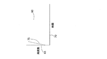
図3は、アパーチャ60から受信したチャープ信号の順方向送信チャープ信号75とエコー信号80を示す。順方向チャープ信号75は、例えば1000Hzの周波数範囲65を有し、例えば1秒の時間区分70に亘って増大して、1000Hz/秒のチャープレートを生成する。様々なチャープパラメータを使用できるが、チャープレートは、レンジ誤差を回避し及び/又は分解能を最適化するために十分に高くなければならない。チャープ75が送信された後、エコー信号80がアパーチャ60から受信される。
FIG. 3 shows a forward
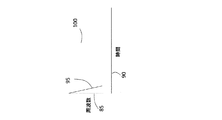
図4は、逆方向送信チャープ信号95と、アパーチャ60から受信したエコー信号100を示す。逆方向チャープ信号95は、例えば1000Hzの周波数レンジ85を有し、例えば1秒の時間区分90に亘って減少する。チャープ95が送信された後でアパーチャ60からエコー信号100が受信される。
FIG. 4 shows the reverse
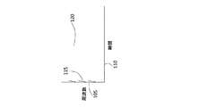
図5は、複数の同時に送信された順方向送信チャープ信号95と、アパーチャ60から受信したエコー信号120を示す。各順方向チャープ信号115は、周波数範囲105を有し、時間区分110に亘って増大する。チャープ信号115が送信された後でアパーチャ60からエコー信号120が受信される。
FIG. 5 shows a plurality of simultaneously transmitted forward transmit
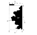
図6は、図15に関して後述されるような、コンピュータ10に実装された1個の整合フィルタ受信機で処理した後の1個の受信機チャネルについての後方散乱信号135a、135b及び135cを示す。信号135a、b,cは、送信機アンテナ25のビーム26内の乱気流から後方散乱される。地面からの乱気流の高度は、高度スケール125によって表わされ、アパーチャ下部126は地面から高度50mにあり、アパーチャ上部127は地面から100mにある。乱気流の振幅は、乱気流レベルスケール130によって表わされ、乱気流閾値131は40である。乱気流の測定値135a,b,cはそれぞれ、航空機が通過した49、56及び63秒後における値が示される。最初の2個の乱気流測定値135a及び135bは、アパーチャ126の下部より上にあり且つ航空機によって引き起こされた後方乱気流による、閾値131を超える高い乱気流を有する。第3の乱気流測定値135cは、アパーチャ126の下部より下にあり且つ航空機によって引き起こされた後方乱気流以外の大気のバックグラウンド乱流レベルによる乱気流を有する。乱気流135cは、乱気流閾値131より上にあるが、乱気流は、アパーチャ126の下部より下である。この場合、アパーチャ内の乱気流は、63秒後に安全閾値131より低い値となって消滅した。
FIG. 6 shows backscattered
図7は、地上145に対する空港滑走路140、進入又は離陸コリドー150、及びコリドー150に沿ったアパーチャ155及び160を示す。送信機及び受信機アレイ165及び170はそれぞれ、アパーチャ155及び160の下に配置される。
FIG. 7 shows an
図8は、航空機によって引き起こされた乱気流がなく且つ航空機によって引き起こされた後方乱気流以外のバックグラウンド大気乱流だけがあるアパーチャ内の比較的低い乱気流を示す。アパーチャの幅180は100mであり、滑走路センターラインを中心にしてプラス及びマイナス方向に50mである。アパーチャの高さ175は、地上より50〜100mである。乱気流グレースケール190は、アパーチャ内の乱気流185の0〜100のレベルを示す。グレースケールが明るいほど乱気流のレベルが低いことを表す。
FIG. 8 shows a relatively low turbulence in the aperture where there is no turbulence caused by the aircraft and there is only background atmospheric turbulence other than wake turbulence caused by the aircraft. The
図9は、航空機によって引き起こされた乱気流が存在するアパーチャ内の比較的高い乱気流を示す。アパーチャの幅200は100mであり、滑走路センターラインを中心にしてプラス及びマイナス方向に50mである。アパーチャの高さ195は、地上より50〜100mである。乱気流グレースケール210は、アパーチャ内の乱気流205のレベルを示す。グレースケールが濃いほど乱気流のレベルが高いことを表す。例えば、グレースケール上の乱気流レベル80に遭遇すると、航空機に45度を超える厳しいロールが生じるであろう。これと対照的に、設定閾値又はレベル(40)の乱気流に遭遇してもほとんど気づかないであろう。
FIG. 9 shows a relatively high turbulence in the aperture where there is turbulence caused by the aircraft. The
乱気流が図9に示されたレベルから図8に示されたレベルまで減少するのにかかる時間が、乱流消滅時間である。乱流が、図8に示されたレベルまで減少した後は、別の航空機が進入又は離陸コリドー上のアパーチャを通過することは安全である。乱流消滅時間は、ACARS等の既存のシステムによって他の航空機に同報通信されてもよく、従来の通信手段によって航空交通管制システムに直接送信されてもよい。 The time taken for the turbulent air flow to decrease from the level shown in FIG. 9 to the level shown in FIG. 8 is the turbulent flow disappearance time. After the turbulence has decreased to the level shown in FIG. 8, it is safe for another aircraft to pass through the aperture on the approach or takeoff corridor. The turbulence extinction time may be broadcast to other aircraft by an existing system such as ACARS, or may be sent directly to the air traffic control system by conventional communication means.
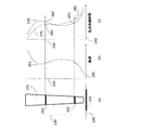
図10a〜図10cは、滑走路コリドー、及びコリドーに沿った関連するウィンドプロファイルと関連する乱流消滅時間を示し、乱流消滅時間は、ウィンドプロファイルと関連して得られる。図10aは、地上220、進入又は離陸端から見た滑走路225、進入又は離陸コリドー245、地上からの高度230、コリドー245内の異なる高度にある2個のアパーチャ250,251を示す。図10bは、滑走路225を横切る方向の風速235の高度230に対する変化を含むウィンドプロファイル265を示す。後方乱気流の消滅時間は、横風265がアパーチャ250,251から後方乱気流205を追い出すのにかかる時間であると考えられる。
FIGS. 10a-10c show runway corridors and turbulence extinction times associated with associated wind profiles along the corridor, where the turbulence extinction times are obtained in relation to the wind profiles. FIG. 10 a shows the
図10cを参照すると、後方乱流消滅時間240の推定プロファイル270が、アパーチャ幅41(図2を参照)を横風速度265で割ることによって得られる。乱流消滅時間が、横風以外の因子によって左右されることがあるので、図10cに示された後方乱流消滅時間の推定プロファイル270は、実際の乱流消滅時間の測定値を得ることによって修正されなければならない。これは、アパーチャ250,251から実際の消滅時間測定値が得られる高度における推定消滅時間270を補正することにより行うことができる。即ち、推定消滅時間255,260を実際の消滅時間280,285に変換することによって行うことができる。次に、推定消滅時間270と新しい値280及び285を使用した補間によって、実際の消滅時間275の完全プロファイルを得ることができる。
Referring to FIG. 10c, an estimated
図11は、比較的効率が高く、サイドローブレベルが低く、アイソレーションが優れているという特性を有する高性能アンテナ構造体の断面図を示し、これらの特性は、乱気流の正確な測定に役立つ。そのようなアンテナ構造は、送信機と受信機の両方に使用されうる。アンテナ構造は、地面285に配置され、垂直方向に向けられうる。アンテナ構造体は、基部290によって地面285に保持されうる。アンテナ構造体の側壁は、円形又は四角形とし、50mmの空気によって分離されたHDPE8mm厚プラスチックの層295及び300から作ることができる。内側には、2個の外側部分の縁を越える音波の回折を最小にするために、比較的高品質のUV安定化吸音発泡材305が、2個の外側層の縁よりも上方に広がっていてもよい。オフセット放物面反射器310は、直径1.2mの衛星アンテナタイプProdelinシリーズ1123を含んでいてもよい。ドライバ315は、40度ホーン320が取り付けられたBMSオーディオタイプ4591を含んでいてもよい。ホーン320は、最適な効率と比較的低いサイドローブレベルを保証するために放物面反射器310の適正な照射を提供することができる。
FIG. 11 shows a cross-sectional view of a high performance antenna structure that has the characteristics of relatively high efficiency, low sidelobe levels, and excellent isolation, which are useful for accurate measurement of turbulence. Such an antenna structure can be used for both transmitter and receiver. The antenna structure can be placed on the
図12は、送信機及び受信機アンテナの変形された構成を示し、送信機と受信機アンテナは、ビーム形状410をそれぞれ有する同じアンテナ装置405を備える。切換スイッチ400は、コンピュータ11によって操作されてもよく、それによりチャープパルス信号が送信されている間に、スイッチ400がアンテナ405を送信機増幅器21に接続する。送信パルスの終わりに、スイッチ400が切り換えられて、アンテナ405が受信機前置増幅器35に接続される。この構成は、アンテナ405の数を半分にすることができるが、送信機増幅器21がアンテナ405に接続されている間の測定について最小レンジも設定する。最小レンジは、送信チャープのパルス幅と音速の半分を掛けたものである。
FIG. 12 shows a modified configuration of the transmitter and receiver antennas, where the transmitter and receiver antennas comprise the
図13は、航空機がアパーチャを通過した後でアパーチャ内の乱気流が設定閾値より低くなるまでの時間を測定するプロセスの例を示す。時間軸500は、航空機がアパーチャを通過するときのゼロから始まり、乱気流軸505は、乱気流の繰り返し測定から得られた乱気流520の実際のレベルを示す。レベル515は、設定乱気流閾値(40)であり、このレベルより低ければ、別の航空機がアパーチャを通過するのは安全であろう。航空機によって引き起こされた乱気流520は、最初に、バックグラウンド乱流レベル510を超え、最終的にある時間期間後にそのレベルに戻る。大気バックグラウンド乱流は時間と共に大きく変化するので、現在の大気乱流510を確定するためにバックグラウンド乱流レベルの移動平均が必要とされ、その現在の大気乱流510から、大気乱流510にマージン530を加えることによって、航空機によって引き起こされた後方乱気流の適正レベル(515)を識別又は取得できる。時間0に航空機がアパーチャを通過してから乱気流が設定閾値より低下するまでの時間期間が乱流消滅時間525である。乱流消滅時間525に安全マージン526を加えることによって、航空機間隔時間527を得ることができる。
FIG. 13 shows an example of a process for measuring the time after the aircraft passes through the aperture until the turbulence in the aperture falls below a set threshold.
図14は、アパーチャが滑走路600に対してどのように測定されるかを示す。滑走路600は、アパーチャ幅620を計算する基礎となる。滑走路610からのアパーチャの距離に0.03を掛けてサイドマージン605を得ることができる。サイドマージン605を滑走路幅615に加えてアパーチャ幅620を得ることができる。地面635からのアパーチャの下側の高度630は、無障害物表面として知られ、各滑走路進入に固有である。アパーチャの高度640は、アパーチャの位置における航空機進入路の高度である。
FIG. 14 shows how the aperture is measured relative to the
図15は、図2のコンピュータ11の要素を示す。コンピュータ11は、foやt(df/dt)(チャープレート)等のチャープパラメータ入力700を有する。デジタル生成されたチャープ730は、サウンドカード16内のD/Aコンバータに加えられて、パワーアンプ21に加えられるアナログチャープ信号735を生成する。受信したアナログエコー信号は、前置増幅器35に加えられて、次にサウンドカード16内のADコンバータに加えられて、デジタル出力740を生成する。デジタル出力740は、整合フィルタ受信機725に加えられる。整合フィルタ受信機725は、2個の構成要素、即ち、整合フィルタ715に加えられる対象周波数範囲を選択する入力FIRデジタルフィルタ710を有する。整合フィルタ715は、周波数領域内で動作して、受信されフィルタリングされたデジタル信号745が、周波数領域内で送信チャープの逆関数(inverse)760と掛けられた(755)後で、逆FFT750から受信信号の大きさ出力720が得られる。大きさ出力720は、大気中の乱流レベルを直接示すものでもよく、大気乱流データ510と実際の乱流レベル520とを提供するために使用されてもよい(図13を参照)。
FIG. 15 shows elements of the
最後に、本発明の趣旨又は範囲から逸脱することなく、前述した部分の構成及び配置に様々な変更、修正及び/又は追加を導入することができることを理解されたい。 Finally, it should be understood that various changes, modifications and / or additions may be made to the structure and arrangement of the parts described above without departing from the spirit or scope of the invention.
10 コンピュータ
15 サウンドカード
20 パワーアンプ
25 送信機アンテナ
30 受信機アンテナ
140 空港滑走路
145 地上
150 進入又は離陸コリドー
155,160 アパーチャ
165 送信機アレイ
170 受信機アレイ
205 後方乱気流
10
Claims (32)
パルス圧縮に適した波形を有する音響信号を前記アパーチャ内に送信する段階と、
前記大気乱流及び/又はウィンドシアからの音響信号の後方散乱音響エコーを受信する段階と、
音響エコーを整合フィルタ受信機内で処理して前記大気乱流の測定を行う段階と、
前記航空機によって引き起こされた後方乱気流を識別して、前記航空機によって引き起こされた後方乱気流及び/又はウィンドシアが少なくとも前記アパーチャ内において設定閾値より低くなるのにかかる時間である消滅時間を決定する段階と、を含む方法。 A method for detecting atmospheric turbulence and / or wind shear including wake turbulence caused by an aircraft in an aperture associated with an aircraft approach or takeoff corridor around an airport, comprising:
Transmitting an acoustic signal having a waveform suitable for pulse compression into the aperture;
Receiving backscattered acoustic echoes of acoustic signals from said atmospheric turbulence and / or wind shear;
Processing acoustic echoes in a matched filter receiver to measure the atmospheric turbulence;
Identifying wake turbulence caused by the aircraft and determining an extinction time, which is the time it takes for the wake turbulence and / or wind shear caused by the aircraft to fall below a set threshold in at least the aperture; , Including methods.
パルス圧縮に適した波形を有する音響信号を前記アパーチャ内に送信する少なくとも1個の送信機アンテナと、
前記大気乱流及び/又はウィンドシアからの音響信号の後方散乱音響エコーを受信する少なくとも1個の受信機アンテナと、
前記音響エコーを処理して前記大気乱流の測定を行う整合フィルタ受信機と、
前記航空機によって引き起こされた後方乱気流を識別して、前記航空機によって引き起こされた後方乱気流及び/又はウィンドシアが少なくとも前記アパーチャ内の設定閾値より低くなるのにかかる時間である消滅時間を決定する手段と、を含むシステム。 A system for detecting atmospheric turbulence and / or wind shear, including wake turbulence caused by aircraft in an aperture associated with an aircraft approach or takeoff corridor around an airport,
At least one transmitter antenna for transmitting an acoustic signal having a waveform suitable for pulse compression into the aperture;
At least one receiver antenna for receiving backscattered acoustic echoes of acoustic signals from said atmospheric turbulence and / or wind shear;
A matched filter receiver that processes the acoustic echo to measure the atmospheric turbulence;
Means for identifying wake turbulence caused by the aircraft and determining an extinction time that is the time it takes for the wake turbulence and / or wind shear caused by the aircraft to be at least below a set threshold in the aperture; , Including system.
Applications Claiming Priority (3)
| Application Number | Priority Date | Filing Date | Title |
|---|---|---|---|
| AU2014901525A AU2014901525A0 (en) | 2014-04-28 | Method and system for detecting aircraft wake turbulence | |
| AU2014901525 | 2014-04-28 | ||
| PCT/AU2015/000238 WO2015164905A1 (en) | 2014-04-28 | 2015-04-21 | Method and system for detecting aircraft induced wake turbulence |
Publications (1)
| Publication Number | Publication Date |
|---|---|
| JP2017516090A true JP2017516090A (en) | 2017-06-15 |
Family
ID=54357903
Family Applications (1)
| Application Number | Title | Priority Date | Filing Date |
|---|---|---|---|
| JP2016564993A Pending JP2017516090A (en) | 2014-04-28 | 2015-04-21 | Method and system for detecting wake turbulence caused by an aircraft |
Country Status (8)
| Country | Link |
|---|---|
| US (1) | US10545234B2 (en) |
| EP (1) | EP3137856A4 (en) |
| JP (1) | JP2017516090A (en) |
| CN (1) | CN106687775A (en) |
| AU (2) | AU2015252745A1 (en) |
| CA (1) | CA2947312A1 (en) |
| SG (2) | SG11201608924SA (en) |
| WO (1) | WO2015164905A1 (en) |
Families Citing this family (7)
| Publication number | Priority date | Publication date | Assignee | Title |
|---|---|---|---|---|
| CN106840598B (en) * | 2017-02-10 | 2019-01-29 | 中国人民解放军国防科学技术大学 | Condition of raining based on side looking radar is got off the plane wake flow circular rector estimation method |
| CN108387885B (en) * | 2018-03-01 | 2020-07-17 | 中国人民解放军国防科技大学 | Aircraft wake characteristic parameter inversion method under clear sky condition based on laser radar detection |
| GB2578893B (en) * | 2018-11-12 | 2021-10-06 | Ge Aviat Systems Ltd | Flight management system and method of updating flight calculations |
| EP3899552A4 (en) * | 2018-12-20 | 2022-11-16 | Electro Magnetic Measurements Pty Ltd | Method for improving performance of a sodar system |
| CN110927693B (en) * | 2019-12-23 | 2021-07-27 | 航天南湖电子信息技术股份有限公司 | Pulse compression method combining matched filtering with sparse inversion |
| CN112193433B (en) * | 2020-09-14 | 2022-02-25 | 中国航天科工集团第二研究院 | Aircraft wake flow detection system and method based on wavefront information |
| CN112419790B (en) * | 2020-11-05 | 2022-05-10 | 南京莱斯信息技术股份有限公司 | Airplane berth departure state detection method |
Family Cites Families (5)
| Publication number | Priority date | Publication date | Assignee | Title |
|---|---|---|---|---|
| US5519618A (en) * | 1993-08-02 | 1996-05-21 | Massachusetts Institute Of Technology | Airport surface safety logic |
| JP3664066B2 (en) * | 2000-10-11 | 2005-06-22 | 三菱電機株式会社 | Air traffic control support system |
| AU2003904198A0 (en) * | 2003-08-11 | 2003-08-21 | Tele-Ip Limited | Detection of wake vortexes and the like in the lower atmosphere |
| US7703319B2 (en) * | 2005-02-28 | 2010-04-27 | Tele-Ip Limited | Characterization of aircraft wake vortices |
| JP5419447B2 (en) * | 2005-06-20 | 2014-02-19 | ウインドビッドコ ピーティーワイ エルティーデー | Observation of lower atmosphere soda |
-
2015
- 2015-04-21 CA CA2947312A patent/CA2947312A1/en not_active Abandoned
- 2015-04-21 US US15/306,926 patent/US10545234B2/en active Active
- 2015-04-21 CN CN201580022992.0A patent/CN106687775A/en active Pending
- 2015-04-21 JP JP2016564993A patent/JP2017516090A/en active Pending
- 2015-04-21 SG SG11201608924SA patent/SG11201608924SA/en unknown
- 2015-04-21 WO PCT/AU2015/000238 patent/WO2015164905A1/en active Application Filing
- 2015-04-21 EP EP15786557.7A patent/EP3137856A4/en not_active Withdrawn
- 2015-04-21 AU AU2015252745A patent/AU2015252745A1/en not_active Abandoned
- 2015-04-21 SG SG10201809319RA patent/SG10201809319RA/en unknown
-
2020
- 2020-09-24 AU AU2020239745A patent/AU2020239745A1/en not_active Abandoned
Also Published As
| Publication number | Publication date |
|---|---|
| SG10201809319RA (en) | 2018-11-29 |
| US20170045615A1 (en) | 2017-02-16 |
| CA2947312A1 (en) | 2015-11-05 |
| WO2015164905A1 (en) | 2015-11-05 |
| AU2015252745A1 (en) | 2016-12-01 |
| EP3137856A1 (en) | 2017-03-08 |
| SG11201608924SA (en) | 2016-11-29 |
| US10545234B2 (en) | 2020-01-28 |
| AU2020239745A1 (en) | 2020-10-22 |
| CN106687775A (en) | 2017-05-17 |
| EP3137856A4 (en) | 2017-12-27 |
Similar Documents
| Publication | Publication Date | Title |
|---|---|---|
| JP2017516090A (en) | Method and system for detecting wake turbulence caused by an aircraft | |
| US20220413121A1 (en) | Radar based system and method for detection of an object and generation of plots holding radial velocity data, and system for detection and classification of unmanned aerial vehicles, uavs | |
| JP2596499B2 (en) | On-board weather radar for wind shear detection. | |
| US7307576B1 (en) | Hazardous and non-hazardous weather identification system and method | |
| US7394723B2 (en) | Atmospheric turbulence hazard detector | |
| US8279109B1 (en) | Aircraft bird strike avoidance method and apparatus using transponder | |
| EP1654562B1 (en) | Detection of wake vortices and the like in the lower atmosphere | |
| US20050232082A1 (en) | Measurement of air characteristics in the lower atmosphere | |
| JPH10227853A (en) | Radar equipment and its radar signal processing method | |
| NO301141B1 (en) | System for detecting and measuring atmospheric movements | |
| US5093662A (en) | Low altitude wind shear detection with airport surveillance radars | |
| Rubin | Radar–acoustic detection of aircraft wake vortices | |
| AU655661B2 (en) | Rainfall detection | |
| US7703319B2 (en) | Characterization of aircraft wake vortices | |
| Finn et al. | The feasibility of unmanned aerial vehicle-based acoustic atmospheric tomography | |
| RU188985U1 (en) | Meteorological Acoustic Doppler Locator with Sound Translucent Dome | |
| CN113866727A (en) | Extreme low-altitude flight target detection power equivalent test method | |
| US20130100773A1 (en) | Wide-area wind velocity profiler | |
| AU2004263911B2 (en) | Detection of wake vortices and the like in the lower atmosphere | |
| Zadeh et al. | Experimental Results on Rain Detection at Ka-Band based on Range-Doppler Signal Processing | |
| Rubin | The generation and detection of sound emitted by aircraft wake vortices in ground effect | |
| AU2006216125B2 (en) | Characterization of aircraft wake vortices | |
| DK201770852A1 (en) | Radar based system and method for detection of an object and generation of plots holding radial velocity data | |
| Buehler et al. | Radar Detection of Turbulence in the Upper Troposphere |