JP2017513643A - Pre-doped solid substrates for intravascular devices - Google Patents
Pre-doped solid substrates for intravascular devices Download PDFInfo
- Publication number
- JP2017513643A JP2017513643A JP2016564309A JP2016564309A JP2017513643A JP 2017513643 A JP2017513643 A JP 2017513643A JP 2016564309 A JP2016564309 A JP 2016564309A JP 2016564309 A JP2016564309 A JP 2016564309A JP 2017513643 A JP2017513643 A JP 2017513643A
- Authority
- JP
- Japan
- Prior art keywords
- flex circuit
- transducer
- polymeric material
- doped
- ultrasound device
- Prior art date
- Legal status (The legal status is an assumption and is not a legal conclusion. Google has not performed a legal analysis and makes no representation as to the accuracy of the status listed.)
- Ceased
Links
- 239000007787 solid Substances 0.000 title abstract description 22
- 239000000758 substrate Substances 0.000 title description 4
- 239000000463 material Substances 0.000 claims abstract description 65
- 238000002608 intravascular ultrasound Methods 0.000 claims abstract description 57
- 238000000034 method Methods 0.000 claims abstract description 27
- 230000007704 transition Effects 0.000 claims description 16
- 239000000853 adhesive Substances 0.000 claims description 10
- 230000001070 adhesive effect Effects 0.000 claims description 10
- 239000003550 marker Substances 0.000 claims description 9
- 239000000126 substance Substances 0.000 claims description 5
- 238000013016 damping Methods 0.000 claims description 3
- 238000001746 injection moulding Methods 0.000 claims description 3
- 239000007769 metal material Substances 0.000 claims 1
- 238000003384 imaging method Methods 0.000 abstract description 31
- 238000002604 ultrasonography Methods 0.000 abstract description 7
- 239000007788 liquid Substances 0.000 description 9
- 238000013461 design Methods 0.000 description 6
- 239000010408 film Substances 0.000 description 6
- 239000011358 absorbing material Substances 0.000 description 4
- 238000004519 manufacturing process Methods 0.000 description 4
- 230000008569 process Effects 0.000 description 4
- 239000010935 stainless steel Substances 0.000 description 4
- 229910001220 stainless steel Inorganic materials 0.000 description 4
- 238000001125 extrusion Methods 0.000 description 3
- 229910052751 metal Inorganic materials 0.000 description 3
- 239000002184 metal Substances 0.000 description 3
- 239000002861 polymer material Substances 0.000 description 3
- 238000012545 processing Methods 0.000 description 3
- 239000004593 Epoxy Substances 0.000 description 2
- PXHVJJICTQNCMI-UHFFFAOYSA-N Nickel Chemical compound [Ni] PXHVJJICTQNCMI-UHFFFAOYSA-N 0.000 description 2
- 239000002033 PVDF binder Substances 0.000 description 2
- 229920002614 Polyether block amide Polymers 0.000 description 2
- 239000004698 Polyethylene Substances 0.000 description 2
- 238000010521 absorption reaction Methods 0.000 description 2
- 230000003321 amplification Effects 0.000 description 2
- 238000013459 approach Methods 0.000 description 2
- 230000008901 benefit Effects 0.000 description 2
- 238000010586 diagram Methods 0.000 description 2
- PCHJSUWPFVWCPO-UHFFFAOYSA-N gold Chemical compound [Au] PCHJSUWPFVWCPO-UHFFFAOYSA-N 0.000 description 2
- 229910052737 gold Inorganic materials 0.000 description 2
- 239000010931 gold Substances 0.000 description 2
- 230000007246 mechanism Effects 0.000 description 2
- 238000003199 nucleic acid amplification method Methods 0.000 description 2
- BASFCYQUMIYNBI-UHFFFAOYSA-N platinum Chemical compound [Pt] BASFCYQUMIYNBI-UHFFFAOYSA-N 0.000 description 2
- 229920003223 poly(pyromellitimide-1,4-diphenyl ether) Polymers 0.000 description 2
- 229920001721 polyimide Polymers 0.000 description 2
- 229920002981 polyvinylidene fluoride Polymers 0.000 description 2
- -1 without limitation Substances 0.000 description 2
- VYZAMTAEIAYCRO-UHFFFAOYSA-N Chromium Chemical compound [Cr] VYZAMTAEIAYCRO-UHFFFAOYSA-N 0.000 description 1
- RYGMFSIKBFXOCR-UHFFFAOYSA-N Copper Chemical compound [Cu] RYGMFSIKBFXOCR-UHFFFAOYSA-N 0.000 description 1
- 239000004677 Nylon Substances 0.000 description 1
- 239000004696 Poly ether ether ketone Substances 0.000 description 1
- 239000004697 Polyetherimide Substances 0.000 description 1
- 239000004642 Polyimide Substances 0.000 description 1
- BQCADISMDOOEFD-UHFFFAOYSA-N Silver Chemical compound [Ag] BQCADISMDOOEFD-UHFFFAOYSA-N 0.000 description 1
- 239000004809 Teflon Substances 0.000 description 1
- 229920006362 Teflon® Polymers 0.000 description 1
- ATJFFYVFTNAWJD-UHFFFAOYSA-N Tin Chemical compound [Sn] ATJFFYVFTNAWJD-UHFFFAOYSA-N 0.000 description 1
- 229920001646 UPILEX Polymers 0.000 description 1
- 230000002776 aggregation Effects 0.000 description 1
- 238000004220 aggregation Methods 0.000 description 1
- 229910045601 alloy Inorganic materials 0.000 description 1
- 239000000956 alloy Substances 0.000 description 1
- 229910052782 aluminium Inorganic materials 0.000 description 1
- XAGFODPZIPBFFR-UHFFFAOYSA-N aluminium Chemical compound [Al] XAGFODPZIPBFFR-UHFFFAOYSA-N 0.000 description 1
- 210000001367 artery Anatomy 0.000 description 1
- 229910052788 barium Inorganic materials 0.000 description 1
- DSAJWYNOEDNPEQ-UHFFFAOYSA-N barium atom Chemical compound [Ba] DSAJWYNOEDNPEQ-UHFFFAOYSA-N 0.000 description 1
- JUPQTSLXMOCDHR-UHFFFAOYSA-N benzene-1,4-diol;bis(4-fluorophenyl)methanone Chemical compound OC1=CC=C(O)C=C1.C1=CC(F)=CC=C1C(=O)C1=CC=C(F)C=C1 JUPQTSLXMOCDHR-UHFFFAOYSA-N 0.000 description 1
- 230000015572 biosynthetic process Effects 0.000 description 1
- 229910052797 bismuth Inorganic materials 0.000 description 1
- JCXGWMGPZLAOME-UHFFFAOYSA-N bismuth atom Chemical compound [Bi] JCXGWMGPZLAOME-UHFFFAOYSA-N 0.000 description 1
- 239000008280 blood Substances 0.000 description 1
- 210000004369 blood Anatomy 0.000 description 1
- 210000004204 blood vessel Anatomy 0.000 description 1
- 210000004556 brain Anatomy 0.000 description 1
- 229910052804 chromium Inorganic materials 0.000 description 1
- 239000011651 chromium Substances 0.000 description 1
- 238000004891 communication Methods 0.000 description 1
- 239000004020 conductor Substances 0.000 description 1
- 229910052802 copper Inorganic materials 0.000 description 1
- 239000010949 copper Substances 0.000 description 1
- 230000008878 coupling Effects 0.000 description 1
- 238000010168 coupling process Methods 0.000 description 1
- 238000005859 coupling reaction Methods 0.000 description 1
- 239000013078 crystal Substances 0.000 description 1
- 238000005520 cutting process Methods 0.000 description 1
- 230000002526 effect on cardiovascular system Effects 0.000 description 1
- 230000000694 effects Effects 0.000 description 1
- 238000005516 engineering process Methods 0.000 description 1
- 238000005530 etching Methods 0.000 description 1
- 229920000840 ethylene tetrafluoroethylene copolymer Polymers 0.000 description 1
- 238000001914 filtration Methods 0.000 description 1
- 210000001145 finger joint Anatomy 0.000 description 1
- 230000006870 function Effects 0.000 description 1
- 210000000232 gallbladder Anatomy 0.000 description 1
- 210000002216 heart Anatomy 0.000 description 1
- 210000003709 heart valve Anatomy 0.000 description 1
- 230000006872 improvement Effects 0.000 description 1
- 238000001727 in vivo Methods 0.000 description 1
- 239000012774 insulation material Substances 0.000 description 1
- 210000000936 intestine Anatomy 0.000 description 1
- 229910052741 iridium Inorganic materials 0.000 description 1
- GKOZUEZYRPOHIO-UHFFFAOYSA-N iridium atom Chemical compound [Ir] GKOZUEZYRPOHIO-UHFFFAOYSA-N 0.000 description 1
- 210000003734 kidney Anatomy 0.000 description 1
- 210000004185 liver Anatomy 0.000 description 1
- 210000004072 lung Anatomy 0.000 description 1
- 238000012986 modification Methods 0.000 description 1
- 230000004048 modification Effects 0.000 description 1
- 238000000465 moulding Methods 0.000 description 1
- 230000001537 neural effect Effects 0.000 description 1
- 229910052759 nickel Inorganic materials 0.000 description 1
- 229910052755 nonmetal Inorganic materials 0.000 description 1
- 229920001778 nylon Polymers 0.000 description 1
- 210000000056 organ Anatomy 0.000 description 1
- 210000000496 pancreas Anatomy 0.000 description 1
- 210000000578 peripheral nerve Anatomy 0.000 description 1
- 230000035699 permeability Effects 0.000 description 1
- 238000007747 plating Methods 0.000 description 1
- 229910052697 platinum Inorganic materials 0.000 description 1
- 229920000052 poly(p-xylylene) Polymers 0.000 description 1
- 239000004417 polycarbonate Substances 0.000 description 1
- 229920000515 polycarbonate Polymers 0.000 description 1
- 229920000728 polyester Polymers 0.000 description 1
- 229920006267 polyester film Polymers 0.000 description 1
- 229920002530 polyetherether ketone Polymers 0.000 description 1
- 229920001601 polyetherimide Polymers 0.000 description 1
- 229920000573 polyethylene Polymers 0.000 description 1
- 229920006290 polyethylene naphthalate film Polymers 0.000 description 1
- 229920000642 polymer Polymers 0.000 description 1
- 229920001343 polytetrafluoroethylene Polymers 0.000 description 1
- 239000004810 polytetrafluoroethylene Substances 0.000 description 1
- 230000001737 promoting effect Effects 0.000 description 1
- 229910052703 rhodium Inorganic materials 0.000 description 1
- 239000010948 rhodium Substances 0.000 description 1
- MHOVAHRLVXNVSD-UHFFFAOYSA-N rhodium atom Chemical compound [Rh] MHOVAHRLVXNVSD-UHFFFAOYSA-N 0.000 description 1
- 239000000523 sample Substances 0.000 description 1
- 229910052709 silver Inorganic materials 0.000 description 1
- 239000004332 silver Substances 0.000 description 1
- 229910000679 solder Inorganic materials 0.000 description 1
- 210000000278 spinal cord Anatomy 0.000 description 1
- 238000004544 sputter deposition Methods 0.000 description 1
- 238000006467 substitution reaction Methods 0.000 description 1
- CCEKAJIANROZEO-UHFFFAOYSA-N sulfluramid Chemical group CCNS(=O)(=O)C(F)(F)C(F)(F)C(F)(F)C(F)(F)C(F)(F)C(F)(F)C(F)(F)C(F)(F)F CCEKAJIANROZEO-UHFFFAOYSA-N 0.000 description 1
- 229910052715 tantalum Inorganic materials 0.000 description 1
- GUVRBAGPIYLISA-UHFFFAOYSA-N tantalum atom Chemical compound [Ta] GUVRBAGPIYLISA-UHFFFAOYSA-N 0.000 description 1
- BFKJFAAPBSQJPD-UHFFFAOYSA-N tetrafluoroethene Chemical compound FC(F)=C(F)F BFKJFAAPBSQJPD-UHFFFAOYSA-N 0.000 description 1
- 239000010409 thin film Substances 0.000 description 1
- 229910052718 tin Inorganic materials 0.000 description 1
- WFKWXMTUELFFGS-UHFFFAOYSA-N tungsten Chemical compound [W] WFKWXMTUELFFGS-UHFFFAOYSA-N 0.000 description 1
- 229910052721 tungsten Inorganic materials 0.000 description 1
- 239000010937 tungsten Substances 0.000 description 1
- 210000003708 urethra Anatomy 0.000 description 1
- 238000004804 winding Methods 0.000 description 1
Images


Classifications
-
- A—HUMAN NECESSITIES
- A61—MEDICAL OR VETERINARY SCIENCE; HYGIENE
- A61B—DIAGNOSIS; SURGERY; IDENTIFICATION
- A61B8/00—Diagnosis using ultrasonic, sonic or infrasonic waves
- A61B8/44—Constructional features of the ultrasonic, sonic or infrasonic diagnostic device
- A61B8/4444—Constructional features of the ultrasonic, sonic or infrasonic diagnostic device related to the probe
- A61B8/445—Details of catheter construction
-
- A—HUMAN NECESSITIES
- A61—MEDICAL OR VETERINARY SCIENCE; HYGIENE
- A61B—DIAGNOSIS; SURGERY; IDENTIFICATION
- A61B8/00—Diagnosis using ultrasonic, sonic or infrasonic waves
- A61B8/08—Detecting organic movements or changes, e.g. tumours, cysts, swellings
- A61B8/0891—Detecting organic movements or changes, e.g. tumours, cysts, swellings for diagnosis of blood vessels
-
- A—HUMAN NECESSITIES
- A61—MEDICAL OR VETERINARY SCIENCE; HYGIENE
- A61B—DIAGNOSIS; SURGERY; IDENTIFICATION
- A61B8/00—Diagnosis using ultrasonic, sonic or infrasonic waves
- A61B8/12—Diagnosis using ultrasonic, sonic or infrasonic waves in body cavities or body tracts, e.g. by using catheters
-
- A—HUMAN NECESSITIES
- A61—MEDICAL OR VETERINARY SCIENCE; HYGIENE
- A61B—DIAGNOSIS; SURGERY; IDENTIFICATION
- A61B8/00—Diagnosis using ultrasonic, sonic or infrasonic waves
- A61B8/44—Constructional features of the ultrasonic, sonic or infrasonic diagnostic device
- A61B8/4483—Constructional features of the ultrasonic, sonic or infrasonic diagnostic device characterised by features of the ultrasound transducer
- A61B8/4494—Constructional features of the ultrasonic, sonic or infrasonic diagnostic device characterised by features of the ultrasound transducer characterised by the arrangement of the transducer elements
-
- B—PERFORMING OPERATIONS; TRANSPORTING
- B06—GENERATING OR TRANSMITTING MECHANICAL VIBRATIONS IN GENERAL
- B06B—METHODS OR APPARATUS FOR GENERATING OR TRANSMITTING MECHANICAL VIBRATIONS OF INFRASONIC, SONIC, OR ULTRASONIC FREQUENCY, e.g. FOR PERFORMING MECHANICAL WORK IN GENERAL
- B06B1/00—Methods or apparatus for generating mechanical vibrations of infrasonic, sonic, or ultrasonic frequency
- B06B1/02—Methods or apparatus for generating mechanical vibrations of infrasonic, sonic, or ultrasonic frequency making use of electrical energy
- B06B1/06—Methods or apparatus for generating mechanical vibrations of infrasonic, sonic, or ultrasonic frequency making use of electrical energy operating with piezoelectric effect or with electrostriction
- B06B1/0644—Methods or apparatus for generating mechanical vibrations of infrasonic, sonic, or ultrasonic frequency making use of electrical energy operating with piezoelectric effect or with electrostriction using a single piezoelectric element
- B06B1/0662—Methods or apparatus for generating mechanical vibrations of infrasonic, sonic, or ultrasonic frequency making use of electrical energy operating with piezoelectric effect or with electrostriction using a single piezoelectric element with an electrode on the sensitive surface
- B06B1/0681—Methods or apparatus for generating mechanical vibrations of infrasonic, sonic, or ultrasonic frequency making use of electrical energy operating with piezoelectric effect or with electrostriction using a single piezoelectric element with an electrode on the sensitive surface and a damping structure
- B06B1/0685—Methods or apparatus for generating mechanical vibrations of infrasonic, sonic, or ultrasonic frequency making use of electrical energy operating with piezoelectric effect or with electrostriction using a single piezoelectric element with an electrode on the sensitive surface and a damping structure on the back only of piezoelectric elements
-
- G—PHYSICS
- G10—MUSICAL INSTRUMENTS; ACOUSTICS
- G10K—SOUND-PRODUCING DEVICES; METHODS OR DEVICES FOR PROTECTING AGAINST, OR FOR DAMPING, NOISE OR OTHER ACOUSTIC WAVES IN GENERAL; ACOUSTICS NOT OTHERWISE PROVIDED FOR
- G10K11/00—Methods or devices for transmitting, conducting or directing sound in general; Methods or devices for protecting against, or for damping, noise or other acoustic waves in general
- G10K11/002—Devices for damping, suppressing, obstructing or conducting sound in acoustic devices
Abstract
システム、デバイス及び方法は、音響減衰物質をドープされた重合物質から成る構造単体に取り付けられている超音波トランスデューサのアレイを含むソリッドステート血管内超音波(IVUS)イメージングシステムを提供する。単体を組み立てるための、音響減衰物質をドープされた重合物質の使用は、IVUSイメージング信号に関連する信号対雑音比を改善するのを助ける。The systems, devices, and methods provide a solid state intravascular ultrasound (IVUS) imaging system that includes an array of ultrasound transducers attached to a structural unit composed of a polymeric material doped with an acoustic attenuating material. The use of a polymeric material doped with a sound attenuating material to assemble the unit helps to improve the signal to noise ratio associated with the IVUS imaging signal.
Description
本開示は、概して、血管内超音波(IVUS;IntraVascular UltraSound)イメージングシステムの音響性能を改善及び最適化することに関係があり、特に、ソリッドステートIVUSイメージングシステムに関係がある。本開示に従う様々な実施形態において、ソリッドステートIVUSイメージングシステムは、フレックス回路へ接続されており且つ構造単体(uni-body)に取り付けられている超音波トランスデューサのアレイを含んでよい。単体は、音響減衰物質をプレドープされた重合物質から成ってよい。このようにして、IVUSイメージングシステムに関連する信号対雑音比、従って、IVUS画像の全体の品質は、改善され得る。 The present disclosure relates generally to improving and optimizing the acoustic performance of intravascular ultrasound (IVUS) imaging systems, and in particular to solid state IVUS imaging systems. In various embodiments in accordance with the present disclosure, a solid state IVUS imaging system may include an array of ultrasound transducers connected to a flex circuit and attached to a uni-body. The simple substance may consist of a polymeric material pre-doped with an acoustic attenuating material. In this way, the signal to noise ratio associated with the IVUS imaging system, and thus the overall quality of the IVUS image, can be improved.
IVUSイメージングシステムは、治療の必要性を判断するために、インターベンションを誘導するために、及び/又は施された治療の有効性を評価するために、患者の身体内の管(例えば、動脈)を評価する診断ツールとして、インターベンショナル心臓学において広く使用されている。IVUSイメージングシステムで広く使用されている血管内デバイスの2つのタイプは、回転式及びソリッドステートである。従来の回転式血管内デバイスは、関心のある管の中に挿入された血管内デバイスの鞘内で継続的に回転するフレキシブル駆動ケーブルを含んでよい。他方で、ソリッドステート血管内デバイスは、トランスデューサ制御回路の組に接続されているデバイスの外周の周りに分布した超音波トランスデューサ(通常は32又は64個)のアレイを含む超音波スキャナアセンブリを持っている。トランスデューサ制御回路は、超音波パルスを送信し且つイメージングのためのエコー信号を受信する個々のトランスデューサ又はトランスデューサのサブセットを選択する。送信−受信トランスデューサ対のシーケンスを経ることによって、ソリッドステート血管内デバイスは、可動部なしで、機械的にスキャンされたトランスデューサ要素の効果を合成することができる。更には、可動部がないので、インターフェイスは単純化され、スキャナアセンブリは、簡単な電気ケーブルによりイメージングシステムへ直接に配線され得る。 IVUS imaging systems can be used to determine the need for treatment, to guide interventions, and / or to evaluate the effectiveness of a given treatment (eg, arteries) within a patient's body. Is widely used in interventional cardiology as a diagnostic tool. Two types of intravascular devices that are widely used in IVUS imaging systems are rotary and solid state. A conventional rotating intravascular device may include a flexible drive cable that rotates continuously within the sheath of the intravascular device inserted into the tube of interest. On the other hand, solid state intravascular devices have an ultrasound scanner assembly that includes an array of ultrasound transducers (typically 32 or 64) distributed around the periphery of the device connected to a set of transducer control circuits. Yes. The transducer control circuit selects individual transducers or a subset of transducers that transmit ultrasound pulses and receive echo signals for imaging. By going through a sequence of transmit-receive transducer pairs, the solid-state intravascular device can synthesize the effects of the mechanically scanned transducer elements without moving parts. Furthermore, since there are no moving parts, the interface is simplified and the scanner assembly can be wired directly to the imaging system by a simple electrical cable.
従来のソリッドステート血管内デバイスにおけるトランスデューサは、通常は、ステンレス鋼単体に巻き付けられているフレックス回路の上に取り付けられる。フレックス回路は、その場合に、ステンレス鋼単体の上に定められる。更には、音響性能を改善するよう、フレックス回路とステンレス鋼単体の表面との間の如何なる空洞も、液状裏当て材を充填される。アセンブリは、次いで、液状裏当て材が固まってくっつくことを可能にするよう硬化される。固まると、如何なる余分の裏当て材も洗浄される。 Transducers in conventional solid state endovascular devices are usually mounted on a flex circuit that is wrapped around a single piece of stainless steel. The flex circuit is then defined on a single piece of stainless steel. Furthermore, any cavities between the flex circuit and the surface of the stainless steel alone are filled with a liquid backing to improve acoustic performance. The assembly is then cured to allow the liquid backing material to set and stick. Once set, any excess backing material is cleaned.
従来のソリッドステート血管内デバイスは、IVUSイメージングの間に高い音響性能を確保することができる。特に、上述されたように、従来のソリッドステート血管内デバイスでは、フレックス回路とステンレス鋼単体の表面との間の空洞は、音響性能を改善するよう液状裏当て材を充填される。しかし、液状裏当て材は、通常、直径が0.007インチである開口を通じて注入されるので、エアポケットは空洞内に形成され得、これは、ソリッドステート血管内デバイスの音響性能を低下させる。また、液状裏当て材の注入により異なった空洞の充電において一貫性を確保する方法はない。従って、音響性能は、トランスデューサの異なった所定のサブセットを使用する場合に、一貫性がなく且つ非一様である。最終的に、アセンブリは、液状裏当て材を硬化するよう加熱され、次いで、如何なる余分の裏当て材も除去するよう洗浄され、それによって、従来のソリッドステート血管内デバイスを製造することに関連した時間及び費用を望ましくなく増大させる。 Conventional solid state intravascular devices can ensure high acoustic performance during IVUS imaging. In particular, as described above, in a conventional solid state endovascular device, the cavity between the flex circuit and the surface of the stainless steel alone is filled with a liquid backing to improve acoustic performance. However, since the liquid backing is typically injected through an opening that is 0.007 inches in diameter, air pockets can be formed in the cavity, which reduces the acoustic performance of the solid state intravascular device. There is no way to ensure consistency in charging different cavities by injecting a liquid backing. Thus, the acoustic performance is inconsistent and non-uniform when using different predetermined subsets of transducers. Finally, the assembly was heated to cure the liquid backing and then washed to remove any excess backing, thereby relating to manufacturing a conventional solid state endovascular device. Undesirably increases time and cost.
そのようなものとして、ソリッドステートIVUSイメージングシステムを製造することに関連した時間及び費用を管理しながら、ソリッドステートIVUSイメージングシステムの音響性能を改善及び最適化する必要性が依然としてある。本願で開示されているデバイス、システム及び方法は、従来のデバイスの欠点の1つ以上を解消する。 As such, there remains a need to improve and optimize the acoustic performance of solid state IVUS imaging systems while managing the time and expense associated with manufacturing solid state IVUS imaging systems. The devices, systems, and methods disclosed herein overcome one or more of the disadvantages of conventional devices.
一態様において、本開示は、スキャナアセンブリを有し、該スキャナアセンブリは、
内腔領域を含むフェルールと、音響減衰物質をドープされた重合物質から成り、前記フェルールの少なくとも一部を囲む単体と、トランスデューサアレイを含み、前記単体の上に取り付けられるフレックス回路とを含む、デバイスを提供する。いくつかの実施形態において、前記フェルール及び前記単体は、形状が円筒型であってよい。更に、前記フェルールは、金属又は重合体から成ってよい。いくつかの実施形態において、前記フェルールの前記内腔領域は、ガイドワイヤを受容するような大きさ及び形状にされてよい。いくつかの実施形態において、前記音響減衰物質は、エポキシのような、如何なるタイプの導電接着剤であってもよい。いくつかの実施形態において、前記重合物質は、前記音響減衰物質を一様にドープされてよい。前記フレックス回路は、前記単体の周りに巻き付けられた構成において前記フレックス回路を巻き付けることによって、前記単体に取り付けられてよい。前記フレックス回路は、接着剤により前記単体に固定されてよい。いくつかの実施形態において、前記単体は複数の放射線不透過マーカーを含んでよい。前記複数の放射線不透過マーカーは、前記単体の外面に固定されている別個の要素を含んでよい。前記単体は、前記複数の放射線不透過マーカーを形成するよう放射線不透過物質をドープされてよい。更には、前記単体は、前記フレックス回路によって覆われている前記単体の部分において少なくとも1つの放射線不透過マーカーを含んでよい。いくつかの実施形態において、前記単体は、制御領域及びトランスデューサ領域を含んでよく、前記制御領域は、前記トランスデューサ領域に対して断面形状を有する。いくつかの実施形態において、前記単体は、非円形断面形状を有する前記制御領域と、円形断面形状を有する前記トランスデューサ領域との間で形状が変化する遷移区間を含んでよい。
In one aspect, the present disclosure includes a scanner assembly, the scanner assembly comprising:
A device comprising a ferrule including a lumen region, a unitary body made of a polymer material doped with a sound attenuating material, surrounding at least a portion of the ferrule, and a flex circuit including a transducer array and mounted on the unitary body I will provide a. In some embodiments, the ferrule and the single body may be cylindrical in shape. Further, the ferrule may be made of metal or polymer. In some embodiments, the lumen region of the ferrule may be sized and shaped to receive a guide wire. In some embodiments, the sound attenuating material may be any type of conductive adhesive, such as an epoxy. In some embodiments, the polymeric material may be uniformly doped with the sound attenuating material. The flex circuit may be attached to the unit by wrapping the flex circuit in a configuration wound around the unit. The flex circuit may be fixed to the single body with an adhesive. In some embodiments, the single body may include a plurality of radiopaque markers. The plurality of radiopaque markers may include separate elements secured to the outer surface of the unitary body. The single body may be doped with a radiopaque material to form the plurality of radiopaque markers. Further, the single piece may include at least one radiopaque marker in the single piece covered by the flex circuit. In some embodiments, the unit may include a control region and a transducer region, the control region having a cross-sectional shape with respect to the transducer region. In some embodiments, the unit may include a transition section that changes shape between the control region having a non-circular cross-sectional shape and the transducer region having a circular cross-sectional shape.
他の態様において、本開示は、血管内超音波(IVUS)デバイスのスキャナアセンブリを提供する方法を提供する。方法は、音響減衰物質をドープされた重合物質を設けるステップと、前記ドープされた重合物質により単体を組み立てるステップと、トランスデューサアレイを備えるフレックス回路を前記組み立てられた単体の上に取り付けるステップとを含んでよい。前記フレックス回路を取り付けるステップは、接着剤を用いて前記フレックス回路を前記単体の上に固定することを含んでよい。いくつかの実施形態において、前記組み立てるステップは、ダイを用いて前記ドープされた重合物質をスエージ加工すること、前記ドープされた重合物質を射出成形すること、及び/又は前記ドープされた重合物質を押出成形することを含んでよい。いくつかの実施形態において、前記単体を設けるステップは、前記音響減衰物質を前記重合物質に一様にドープすることを含んでよい。方法は、複数の放射線不透過マーカーを前記単体の外面に固定するステップを更に含んでよい。いくつかの実施形態において、前記複数の放射線不透過マーカーは別個の要素であってよい。いくつかの実施形態において、前記単体は、複数の放射線不透過マーカーを形成するよう放射線不透過物質をドープされてよい。いくつかの実施形態において、少なくとも1つの放射線不透過マーカーは、前記フレックス回路によって覆われている前記単体の部分において設けられてよい。 In another aspect, the present disclosure provides a method of providing a scanner assembly for an intravascular ultrasound (IVUS) device. The method includes providing a polymeric material doped with an acoustic damping material, assembling a unitary body with the doped polymeric material, and mounting a flex circuit comprising a transducer array on the assembled unitary body. It's okay. The step of attaching the flex circuit may include securing the flex circuit onto the unit using an adhesive. In some embodiments, the step of assembling includes swaging the doped polymeric material using a die, injection molding the doped polymeric material, and / or the doped polymeric material. Extruding may be included. In some embodiments, the step of providing the simple substance may comprise uniformly doping the polymeric material with the sound attenuating material. The method may further comprise securing a plurality of radiopaque markers to the outer surface of the unit. In some embodiments, the plurality of radiopaque markers may be separate elements. In some embodiments, the single body may be doped with a radiopaque material to form a plurality of radiopaque markers. In some embodiments, at least one radiopaque marker may be provided in the unitary portion covered by the flex circuit.
前述の概要及び以下の詳細な説明はいずれも、当然ながら例及び説明であり、本開示の適用範囲を制限することなしに本開示の理解を提供することを目的とする点が理解されるべきである。それに関連して、本開示の更なる態様、特徴、及び利点は、以下の詳細な説明から当業者に明らかであろう。 It is to be understood that both the foregoing summary and the following detailed description are, of course, examples and descriptions, and are intended to provide an understanding of the present disclosure without limiting the scope of the disclosure. It is. In that regard, further aspects, features, and advantages of the present disclosure will be apparent to those skilled in the art from the following detailed description.
添付の図面は、本願において説明を伴って開示されているデバイス及び方法の実施形態を表し、本開示の原理を説明するのに役立つ。本明細書の全体を通じて、同じ要素は、記載されているどの実施形態でも、同じ参照符号により参照されるときはいつでも、共通の要素を指す。一箇所において特定の要素に帰するとされた特性、属性、機能、相互関係は、特段別なふうに示されない限りは、他の箇所で同じ参照符号によって参照される場合にそれらの要素に当てはまる。 The accompanying drawings illustrate embodiments of the devices and methods disclosed with the description herein and serve to explain the principles of the disclosure. Throughout this specification, the same elements refer to common elements, whenever referred to by the same reference numerals, in any of the described embodiments. Properties, attributes, functions, and interrelationships attributed to a particular element in one location apply to those elements when referred to by the same reference signs elsewhere unless otherwise indicated.
以下で参照される図は、単に、本開示の基礎的な教示の説明を簡単にするために、描かれている。次の実施形態を形成する部分の数、位置、関係、及び寸法に対する図の拡張は、説明されるか、あるいは、以下の説明が読まれ理解された後に当業者が備えている技能の範囲内にある。更には、特定の力、重さ、強さ、及び同様の要件に従うための正確な寸法及び寸法比は、以下の説明が読まれ理解された後に同様に当業者が備えている技能の範囲内にある。 The figures referenced below are merely drawn to simplify the description of the basic teachings of the present disclosure. Drawing extensions to the number, position, relationship, and dimensions of the parts forming the following embodiments will be described or within the skill of one skilled in the art after the following description has been read and understood. It is in. Furthermore, the exact dimensions and size ratios to comply with specific forces, weights, strengths, and similar requirements are within the skill of those skilled in the art as well after reading and understanding the following description. It is in.
以下は、本発明を記載するために使用される夫々の図の簡単な説明であり、よって、単に実例を目的として提示されており、本発明の適用範囲を制限すべきではない。
本開示の原理の理解を促すことを目的として、これより、図面に表されている実施形態が参照され、特殊言語は、それらの実施形態を記載するために使用される。それでもなお、本開示の適用範囲への制限は意図されないことが理解される。記載されているデバイス、システム、及び方法、並びに本開示の原理の如何なる更なる用途への如何なる変更及び更なる改良も、本開示が関係している技術において通常の知識を有する者に普通に思い浮かぶように、十分に熟考され、本開示内に含まれている。例えば、IVUSシステムは、心臓血管イメージングに関して記載されているが、この用途に制限されるよう意図されないことが理解される。システムは、密閉されたキャビティ内のイメージングを必要とする如何なる用途にも同様に適している。特に、一実施形態に関して記載されている特徴、コンポーネント、及び/又はステップは、本開示の他の実施形態に関して記載されている特徴、コンポーネント、及び/又はステップと組み合わされてよいことが十分に熟考されている。簡潔さのために、それらの組み合わせの多数の繰り返しは、別々に記載されない。 For the purposes of promoting an understanding of the principles of the disclosure, reference will now be made to the embodiments illustrated in the drawings, and special language will be used to describe those embodiments. Nevertheless, it is understood that no limitation to the scope of the present disclosure is intended. Any changes and further improvements to the described devices, systems, and methods, and any further uses of the principles of the present disclosure will be common to those having ordinary skill in the art to which this disclosure pertains. As such, it is well contemplated and included within this disclosure. For example, although an IVUS system has been described for cardiovascular imaging, it is understood that it is not intended to be limited to this application. The system is equally suitable for any application that requires imaging in a sealed cavity. In particular, it is sufficiently contemplated that features, components, and / or steps described with respect to one embodiment may be combined with features, components, and / or steps described with respect to other embodiments of the present disclosure. Has been. For brevity, many repetitions of these combinations are not described separately.
上述されたように、ソリッドステートIVUSイメージングシステムの音響性能を改善及び最適化する必要性がある。本開示は、血管内超音波(IVUS)イメージングシステム、特に、ソリッドステートIVUSイメージングシステムの音響性能を改善し且つ最適化するデバイス、システム、及び方法を記載する。特に、本開示は、音響減衰物質を注入又はプレドープされた重合物質でできている構造単体においてIVUSトランスデューサ及びフレックス回路を取り付けることを開示する。音響減衰物質をプレドープされた重合物質の使用は、単体の長さ全体にわたって一貫した音響吸収を可能にし、IVUS信号に関連した信号対雑音比を改善する。これは、IVUSイメージングシステムの全体の音響性能を最適化する。また、単体を構成する固体のプレドープされた重合物質の使用は、如何なる液状裏当て材も使用する必要性を排除する。そのようなものとして、本開示提案されているデバイス及びシステムの実施形態は、従来のソリッドステートIVUSイメージングシステムに関して観測され得る一貫性がなく且つ非一様な音響性能を回避する。更には、目下開示されているデバイス及びシステムの実施形態は、如何なる液状裏当て材も加熱及び硬化する必要がないので、改善された製造可能性を有する。ソリッドステートIVUSシステムを製造することに関連した全体のコストも削減される。 As mentioned above, there is a need to improve and optimize the acoustic performance of solid state IVUS imaging systems. The present disclosure describes devices, systems, and methods for improving and optimizing the acoustic performance of intravascular ultrasound (IVUS) imaging systems, particularly solid state IVUS imaging systems. In particular, the present disclosure discloses mounting the IVUS transducer and flex circuit in a unitary structure made of a polymeric material that is injected or pre-doped with an acoustic attenuating material. The use of a polymeric material pre-doped with an acoustic attenuating material allows for consistent acoustic absorption throughout the length of a single unit and improves the signal to noise ratio associated with the IVUS signal. This optimizes the overall acoustic performance of the IVUS imaging system. Also, the use of a solid pre-doped polymeric material that constitutes a single unit eliminates the need to use any liquid backing material. As such, the proposed device and system embodiments of the present disclosure avoid inconsistent and non-uniform acoustic performance that can be observed with conventional solid state IVUS imaging systems. Furthermore, the presently disclosed device and system embodiments have improved manufacturability because no liquid backing need be heated and cured. The overall cost associated with manufacturing a solid state IVUS system is also reduced.
図1は、本開示の実施形態に従う血管内超音波(IVUS)イメージングシステム100の概略図である。いくつかの実施形態において、IVUSイメージングシステム100は、圧電性ジルコン酸塩トランスデューサ(PZT;piezoelectric zirconate transducer)ソリッドステートIVUSイメージングシステムであってよい。他の実施形態では、システム100は、容量性マイクロマシン超音波トランスデューサ(CMUT;capacitive micromachined ultrasonic transducer)、及び/又は圧電型マイクロマシン超音波トランスデューサ(PMUT;piezoelectric micromachined ultrasonic transducer)を組み込んでよい。IVUSイメージングシステム100は、IVUS血管内デバイス102、患者インターフェイスモジュール(PIM;patient interface module)104、IVUSコンソール若しくはプロセッシングシステム106、及び/又はモニタ108を含んでよい。
FIG. 1 is a schematic diagram of an intravascular ultrasound (IVUS)
高いレベルで、IVUS血管内デバイス102は、イメージングシステム100の遠位端にあるスキャナアセンブリ110に含まれるトランスデューサから超音波エネルギを発する。超音波エネルギは、スキャナ110を囲む組織構造によって反射され、組織からのエコー信号は、スキャナ110に含まれている回路によって受信され増幅されてよい。PIM104は、スキャナアセンブリ110の動作を制御するようIVUSコンソール106とIVUS血管内デバイス102との間の信号の通信を助けてよい。これは、スキャナを設定し、送信器回路をトリガする制御信号を生成及び/又は供給することと、スキャナアセンブリ110によって捕捉されたエコー信号をIVUSコンソール106へ転送することとを含んでよい。エコー信号に関して、PIM104は、受信された信号を転送してよく、いくつかの実施形態では、信号をコンソール106へ転送する前に予備的な信号処理を実施してよい。例えば、PIM104は、信号をコンソール106へ転送する前に、データの増幅、フィルタリング、及び/又は集約を実施してよい。一実施形態において、PIM104はまた、スキャナ100内の回路の動作をサポートするようハイ及びロー電圧DC電力を供給してよい。IVUSコンソール106は、PIM104を経由してスキャナ110からエコーデータを受け取ってよく、スキャナ100を囲む組織の画像を生成するようデータを処理してよい。コンソール106はまた、モニタ108において画像を表示してよい。
At a high level, the IVUS
いくつかの実施形態において、血管内デバイスは、Volcano Corporationから入手可能なEagleEye(登録商標)カテーテル、及び米国特許第7846101号で開示されているもののような、旧来のソリッドステート血管内デバイスと同様のいくつかの機構を含む。なお、米国特許第7846101号は、その全文を参照により本願に援用される。例えば、IVUSデバイス102は、デバイス102の遠位端にある超音波スキャナアセンブリ110と、デバイス102の縦長の本体に沿って延在するケーブル112とを含んでよい。ケーブル112は、デバイス102の近位端にあるコネクタ114において終端してよい。コネクタ114は、ケーブル112をPIM104へ電気的に結合してよく、IVUSデバイス102をPIM104へ物理的に接続してよい。いくつかの実施形態において、IVUSデバイス102は、ガイドワイヤ出口ポート116を更に含んでよい。然るに、いくつかの場合に、IVUSデバイスは、ラピッドエクスチェンジ・カテーテルであってよい。ガイドワイヤ出口ポート116は、ガイドワイヤ118が、デバイス102を管120に通すために、遠位端に向かって挿入されることを可能にしてよい。管120は、撮像され得る生体内の液体で満たされた又は囲まれた自然又は人工の構造物に相当してよく、例えば、制限なしに、肝臓、心臓、腎臓、胆嚢、膵臓、肺を含む臓器;ダクト;腸;脳、硬膜嚢、脊髄及び末梢神経を含む神経系統;尿道;並びに身体の血液又は他の系統内の弁を含むことができる。自然の構造物を撮像することに加えて、画像は、例えば、制限なしに、心臓弁、ステント、シャント、フィルタ、及び身体内に置かれた他のデバイスのような、人工構造物を撮像することを更に含んでよい。実施形態において、IVUSデバイス102は、遠位端の近くにある可膨張バルーン部122を含んでよい。バルーン部122は、IVUSデバイスの長さに沿って移動し、膨張部(図示せず。)において終わる内腔に開かれてよい。バルーン122は、膨張部を介して選択的に膨張又は収縮してよい。
In some embodiments, the intravascular device is similar to traditional solid state intravascular devices, such as the EagleEye® catheter available from Volcano Corporation, and the one disclosed in US Pat. No. 7,846,101. Includes several mechanisms. U.S. Pat. No. 7,846,101 is hereby incorporated by reference in its entirety. For example, the
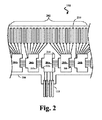
図2は、本開示の実施形態に従う超音波スキャナアセンブリ110の部分の上面図である。図2は、超音波スキャナアセンブリ110をその平坦な形態において表す。スキャナアセンブリ110は、フレックス回路206に取り付けられているトランスデューサアレイ202及びトランスデューサ制御回路204(コントローラ204a及び204bを含む。)を含んでよい。トランスデューサアレイ202は、如何なる個数及びタイプの超音波エコートランスデューサ210も含んでよい。なお、明りょうさのために、図2では、限られた数の超音波トランスデューサしか表されていない。いくつかの実施形態において、トランスデューサアレイ202は、64個の個別的な超音波トランスデューサ210を含んでよい。いくつかの実施形態において、トランスデューサアレイ202は、32個の超音波トランスデューサを含んでよい。他の個数が考えられており、提供される。いくつかの実施形態において、トランスデューサアレイ202の超音波トランスデューサ210は、例えば、米国特許第6641540号で開示されているような、高分子圧電材を用いて微小電気機械システム(MEMS;microelectromechanical system)基材の上に製造された圧電型マイクロマシン超音波トランスデューサ(PMUT)であってよい。なお、米国特許第6641540号は、その全文を参照により本願に援用される。代替の実施形態では、トランスデューサアレイは、バルクPZTトランスデューサ、容量性マイクロマシン超音波トランスデューサ(CMUT)、単結晶圧電材、他の適切な超音波送信器及び受信機、並びに/又はそれらの組み合わせのような、圧電性ジルコン酸塩トランスデューサ(PZT)を含んでよい。
FIG. 2 is a top view of a portion of an
表されている実施形態では、スキャナアセンブリ110は、9個のトランスデューサ制御回路204を含んでよく、そのうちの5個が図示されている。4、8、9、16、17及びそれ以上を含む他の個数のトランスデューサ制御回路204を組み込む設計は、他の実施形態において利用されてよい。いくつかの実施形態では、単一のコントローラがマスタコントローラに指定されてよく、ケーブル112から直接に信号を受信するよう構成されてよい。残りのコントローラはスレーブコントローラであってよい。表されている実施形態では、マスタコントローラ204aは、いずれのトランスデューサ210も直接に制御しない。他の実施形態では、マスタコントローラ204aは、スレーブコントローラ204bと同数のトランスデューサ210を有してよく、あるいは、スレーブコントローラ204bと比較して少ないトランスデューサ210の組を有してよい。表されている実施形態では、単一のマスタコントローラ204a及び8個のスレーブコントローラ204bが設けられている。8個のトランスデューサは、夫々のスレーブコントローラ204bへ割り当てられてよい。そのようなコントローラは、それらが駆動することができるトランスデューサの数に基づき8チャネルコントローラと称され得る。
In the illustrated embodiment, the
マスタコントローラ204aは、設定データに基づきスレーブコントローラ204bのための夫々の制御信号を生成及び/又は供給し、且つ、ケーブル112を介して受信されたトリガを送信してよい。マスタコントローラ204aはまた、スレーブコントローラ204bからエコーデータを受け取って、該エコーデータをケーブル112を介して再送信してよい。そうするよう、いくつかの実施形態では、マスタコントローラ204aは、エコー増幅器(図示せず。)を含んでよい。この構成において、マスタコントローラ204aは、増幅されていないか又は部分的に増幅されたエコーデータを受け取ってよく、そして、ケーブル112に沿ってエコーデータを駆動するための必要な増幅を実施してよい。
The master controller 204a may generate and / or supply respective control signals for the
実施形態において、フレックス回路206は、構造支持体を提供してよく、トランスデューサ制御回路204を夫々のトランスデューサ210へ物理的且つ電気的に接続してよい。フレックス回路206は、KAPTON(デュポンの登録商標)のような可撓性のポリイミド材のフィルム層を含んでよい。他の適切な材料は、ポリエステルフィルム、ポリイミドフィルム、ポリエチレン・ナフタレートフィルム、又はポリエーテルイミドフィルム、及び他の可撓性の印刷回路基板、並びにUpilex(宇部興産株式会社の登録商標)及びTEFLON(E.I.デュポンの登録商標)を含む。本開示に従って、フィルム層は、いくつかの場合に円筒形トロイドを形成するように単体構造に巻き付けられるよう構成されてよい。従って、フィルム層の厚さは、一般に、スキャナアセンブリ110における湾曲の程度に関係があってよい。いくつかの実施形態において、フィルム層は、5μmから100μmの間であってよく、いくつかの特定の実施形態によれば、12.7μmから25m1μmの間であってよい。
In embodiments, the
いくつかの実施形態において、フレックス回路206は、フィルム層に形成された導電性トレースを更に含んでよい。そのような導電性トレースは、トランスデューサ制御回路204とトランスデューサ210との間で信号を運んでよく、且つ、ケーブル112の導体を接続するパッドの組を提供してよい。導電性トレースのための適切な材料は、銅、金、アルミニウム、銀、タンタル、ニッケル、及びスズを含み、スパッタリング、めっき、及びエッチングのような加工によってフレックス回路206に溶着されてよい。いくつかの実施形態において、フレックス回路206はクロム密着層を含んでよい。導電性トレースの幅及び厚さは、フレックス回路206がトロイドを形成するよう丸められる場合に適切な導電性及び弾性を提供するよう選択されてよい。それに関連して、導電性トレースの厚さの範囲の例は10から50μの間であってよい。例えば、実施形態において、20μmの導電性トレースは、20μmの間隔で分けられてよい。導電性トレースの幅は、トレースに結合されるワイヤの幅又はデバイスのパッドのサイズによって更に決定されてよい。
In some embodiments, the
回路は、完成したスキャナアセンブリを形成するよう丸められ得るので、マスタコントローラ及びスレーブコントローラの両方を含む制御回路204は、然るべく成形されてよい。これは、隣接する制御回路204の端とインターフェイス接続するよう構成された制御回路204の端を含んでよい。いくつかの実施形態において、制御回路204は、互いに噛み合う歯212a及び212bを含んでよい。例えば、制御回路204は、ボックスジョイント又はフィンガージョイントを形成するよう隣接する制御回路204の凹凸212bと噛み合う凹凸212aを有して形成されてよい。いくつかの実施形態において、制御回路204は、単独で又は凹凸と組み合わせて、面取り縁214を含んでよい。面取り縁214は、隣接する制御回路204の端に接するよう構成されてよい。いくつかのそのような実施形態では、隣接する制御回路の端は、同様に面取りされてよい。いくつかの実施形態において、コントローラ204の夫々は、同様の凹凸インターフェイスを用いて2つの隣接するコントローラと噛み合ってよい。
Since the circuit can be rolled to form a completed scanner assembly, the control circuit 204 including both the master controller and the slave controller may be shaped accordingly. This may include the end of the control circuit 204 configured to interface with the end of the adjacent control circuit 204. In some embodiments, the control circuit 204 may include teeth 212a and 212b that mesh with each other. For example, the control circuit 204 may be formed with an unevenness 212a that meshes with the unevenness 212b of the adjacent control circuit 204 to form a box joint or a finger joint. In some embodiments, the control circuit 204 may include a
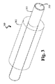
図3は、本開示の実施形態に従う例となる取付構造300を表す。取付構造300は、固体単体302によって少なくとも部分的に囲まれているフェルール301を含んでよい。一実施形態では、フェルール301は円筒形状を有してよい。なお、フェルール301の他の形状も、幾何学的、非幾何学的、対称的、非対称的、断面形状を含め、考えられる。フェルール301は、金属又は非金属基板から形成されてよい。フェルール301内の内腔領域303は、開いており、ガイドワイヤ出口ポート116と連通し、それによって、スキャナアセンブリ110及び関連する血管内デバイスがガイドワイヤにわたって進めるようにすることができる。いくつかの実施形態において、単体302は、スキャナアセンブリ110の円筒形状に適合するよう円筒形状を有する。単体302は、音響吸収物質を注入又はプレドープされた重合物質から成ってよい。重合物質は、ナイロン、ペバックス(登録商標)、PE、カプトン(登録商標)、PTFE、PVDF、ポリカーボネイト、PEEK(登録商標)、PET ETFE、又は何らかの他のタイプの押し出し若しくはモールド加工された管類であってよい。音響吸収物質は、エポキシのような、如何なるタイプの導電接着剤であってもよい。いくつかの実施形態において、フレックス回路206は、取付構造300において取り付けられ、又は実装されてよい。例えば、フレックス回路206は、単体302の周りに巻き付けられた構成においてフレックス回路206を巻き付けることによって、単体302に実装されてよい。更には、又は選択的に、フレックス回路206は、トランスデューサアレイ202を含み、如何なる反響又は音響障害も更に制限するよう接着剤により単体302の外面に固定されてよい。単体302は、フレックス回路206及び接続されているトランスデューサアレイ202を適切に支持することができる重合物質から成る固体構造物であってよい。音響吸収物質を一様にドープされている重合物質の使用は、単体302の長さ全体にわたる一貫した音の吸収を可能にする。これは、トランスデューサ210によって与えられるエコー信号及び超音波パルスに関連した信号対雑音比を改善し、それによって、IVUSイメージングシステムの全体の音響性能を最適化する。
FIG. 3 depicts an
いくつかの実施形態において、単体302は、中が空洞の円筒形ダイを通るプレドープされたポリマー材料をスエージ加工することによって製造されてよい。いくつかの実施形態において、単体302の所望の形状のモールドが設計されてよく、プレドープされた重合物質がモールド内に注入されてよい。いくつかの実施形態において、単体302は、所望の断面形状を有する構造体を作るよう押し出し加工を使用することによって製造されてよい。切断、完了、破砕、テーパリング、テクスチャリング、などのような追加の加工は、単体302を画定するよう、モールド、スエージ及び/又は押し出し加工された構造体に対して実施されてよい。
In some embodiments, the
図4は、本開示の実施形態に従う他の例となる取付構造400を表す。表されている実施形態では、単体302は、複数の放射線不透過マーカー410を含んでよい。いくつかの実施形態において、単体の重合物質は、単体上の所望の位置において放射線不透過マーカー410を形成するよう、放射線不透過物質をドープ及び/又はコーティングされる。他の実施形態では、放射線不透過マーカー410は、単体302の外面上に固定して貼り付けられた円周バンドのような別個の要素であってよい。放射線不透過マーカー410は、制限なしに、金、タングステン、イリジウム、ロジウム、白金、バリウム、ビスマス、並びにそれらの結合及び/又は合金を含む1つ以上の放射線不透過物質から形成されてよい。一実施形態では、単体302は、フレックス回路206及びトランスデューサ210によって覆われている部分において複数の放射線不透過マーカーを含んでよい。他の実施形態では、単体302は、単体302の大部分又は全体の長さに沿って複数の放射線不透過マーカーを含んでよい。複数の放射線不透過マーカーは、等しい又は可変なサイズであってよく、単体302において等距離の所に又は可変的に位置づけられてよい。一実施形態では、放射線不透過マーカーの幅は、2つの隣接する放射線不透過マーカーの間の距離に略等しいか又はそれに比例してよい。IVUSデバイス102が患者の身体に挿入されるとオペレータがトランスデューサ210の位置を正確に観測及び追跡することを可能にするよう、フレックス回路206及びトランスデューサ210によって覆われている部分において複数の放射線不透過マーカーを含むことが有利である。トランスデューサ210の正確な位置を知ることは、イメージングのために関心のある管内の所望の位置におけるトランスデューサ210の正確な配置を可能にする。これは、オペレータが、イメージングプロシージャの間に、デバイス102内のトランスデューサ210の位置を推測又は推定するよう求められる場合を減らすことができる。そのようなものとして、イメージングプロシージャの全体の効率は高められる。放射線不透過マーカーは、他のタイプの血管内の又は血管外で得られた患者データに対する血管内デバイスにより得られた画像のコレジストレーションを助けるよう血管内デバイス及び/又はトランスデューサの位置を追跡するためにも利用され得る。
FIG. 4 depicts another
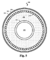
図5は、本開示の実施形態に従うスキャナアセンブリ110のトランスデューサ領域500の断面図を表す。表されている実施形態では、トランスデューサ領域500は、その巻かれた形において表されている。それに関して、いくつかの場合に、スキャナは、平坦構成から巻かれた又は更には円筒型の構成へ変化する。例えば、いくつかの実施形態において、技術は、“ULTRASONIC TRANSDUCER ARRAY AND METHOD OF MANUFACTURING THE SAME”と題された米国特許第6776763号、及び“HIGH RESOLUTION INTRAVASCULAR ULTRASOUND TRANSDUCER ASSEMBLY HAVING A FLEXIBLE SUBSTRATE”と題された米国特許第7226418号のうちの1つ以上において開示されているように利用される。なお、それらの特許文献の夫々は、その全文を参照により本願に援用される。
FIG. 5 depicts a cross-sectional view of
名称が示すように、スキャナのトランスデューサ領域500は、フレックス回路206に、特に、フレックス回路206のトレースに取り付けられているトランスデューサを含む。表されている実施形態では、フレックス回路206は、導電接地レイヤ502と、接地レイヤ502を絶縁し覆うために且つスキャナを環境から保護するために使用される外側部材504とを更に含んでよい。外側部材504のための絶縁材は、それらの生体適合性、耐久性、親水性若しくは疎水性、低摩擦特性、超音波浸透性、及び/又は他の適切な基準のために選択されてよい。例えば、外側部材はParylene(ユニオン・カーバイドの登録商標)を含んでよい。他の適切な材料は、ポリエステル若しくはPVDFのような熱収縮チューブ、Pebax(アルケマ社の登録商標)若しくはポリエチレンのような溶融成形可能なレイヤ、及び/又は他の適切な薄膜材料を含む。示されるように、超音波トランスデューサ210のサイズ、形状、及び間隔は、トランスデューサ領域500の形状を少なくとも部分的に画定する。64個の超音波トランスデューサ210を有する実施形態では、トランスデューサ領域500の断面は、図示されるように、円形又は略円形であってよい。
As the name implies, the
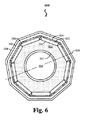
図6は、本開示の実施形態に従う超音波スキャナアセンブリ110の制御領域600の断面図を表す。制御領域600は、フレックス回路206へ接続されている9個のトランスデューサ制御回路204を含んでよい。いくつかの実施形態において、制御回路204は、フレックス回路206の夫々のトレースへ制御回路を結合するよう夫々の接点バンプ602を含んでよい。形成の間に、接点は加熱されてよく、半田が流れて接点バンプ602のメタルコアをフレックス回路206のトレースと接続させる。アンダーフィル材料604は、結合強度を強め且つ制御領域の構造支持を提供するよう、制御回路204とフレックス回路206との間に適用されてよい。アンダーフィル材料604はまた、接点バンプ602を含む導電構造体を絶縁し、且つ、熱伝導を促してよい。トランスデューサ制御回路204に隣接するフレックス回路206の部分は平坦であるから、より少ないがより大きい制御回路に代えて、より狭いがより多いトランスデューサ制御回路204を利用することは、より円形の断面を生じる。その結果として、8個、9個、16個又はそれ以上のトランスデューサ制御回路204を利用する設計は、4個又は5個のトランスデューサ制御回路204による設計よりも円形の断面を有することになる。これは、スキャナアセンブリ110の有効径608を小さくするという利点を有する。更には、より狭いトランスデューサ制御回路204が使用され得るので、デバイス102の長手軸に沿った非可撓性の制御領域600の長さは低減され得る。
FIG. 6 depicts a cross-sectional view of the
加えて、より円形の断面を生じするためにより狭く且つより多いトランスデューサ制御回路204を利用することは、それがより短い遷移区間を可能にするので、有利である。図7は、本開示の実施形態に従う例となる超音波スキャナアセンブリ110の部分の斜視図を表す。スキャナアセンブリ110は、フェルール701及び単体702を含んでよい。単体702は、トランスデューサ領域500、制御領域600、及び遷移区間700を含んでよい。いくつかの実施形態において、制御領域600の形態又は形状は、収容されるトランスデューサ制御回路204の数に基づいてよい。例えば、一実施形態では、制御領域600の形状は、4個のトランスデューサ制御回路204を収容するよう正方形のようであってよい。いくつかの実施形態において、制御領域600の形状は、8個のトランスデューサ制御回路204を収容するよう八角形のようであってよい。いくつかの実施形態において、9個のトランスデューサ制御回路204が収容されるよう設計され、制御領域600の形状は、図6に表されるように、九角形のようであってよい。
In addition, utilizing a narrower and more transducer control circuit 204 to produce a more circular cross-section is advantageous because it allows for a shorter transition interval. FIG. 7 depicts a perspective view of a portion of an example
遷移区間700は、トランスデューサ領域500と制御領域600との間に位置してよい。トランスデューサ領域500及び制御領域600と対照的に、遷移区間700は、剛構造がない。遷移区間700の断面形状は、いくつかの場合に、隣接する領域500及び600によって画定される。一般に、遷移区間700の断面形状は、トランスデューサ領域500の断面形状と制御領域600の断面形状との間で変化する。遷移区間700は、フレックス回路206及び/又は導電トレースにストレスを加えうる鋭角を減らすために使用されてよい。本開示で提案されている関連する制御領域600のより円形の断面により、例えば、8個、9個、16個又はそれ以上のトランスデューサ制御回路204を利用する実施形態は、より短い遷移区間700を支援する。すなわち、トランスデューサ制御回路204及び超音波トランスデューサ210はいずれもフレックス回路206内で平坦領域を生じさせるので、物理的により狭いデバイスを代用することは、夫々の個々のデバイスによって引き起こされるフレックス回路206の非円形領域を減らす。従って、例えば、9個のトランスデューサ制御回路を利用する設計は、4個のトランスデューサ制御回路204を利用する設計に対してより円形の制御領域600を有し、更には、より短い遷移区間700を提供する。4個の制御回路204による例となる実施形態では、遷移区間700は、略正方形形状から略円形形状へ変化するために、おおよそ1から1.5カテーテル直径である。これは、3Frカテーテルについて1000から1500μmであるということになる。対照的に、9個の制御回路204の実施によれば、遷移区間700は、おおよそ0.5から0.75カテーテル直径、すなわち、3Frカテーテルについて500μmから750μmである。このようにして、より狭く且つより多いトランスデューサ制御回路204を組み込む設計は、より短いスキャナアセンブリ110をもたらし得る。スキャナアセンブリ110は、デバイスの周囲部分と比較して、通常は柔軟性がなく、すなわち硬いので、アセンブリ110の長さを低減することは、複雑な血管枝を通って誘導することができ且つ患者への不快感が少ない、よりアジャイルなIVUSデバイスをもたらす。
The
上述されたように、単体702は、トランスデューサ領域500、制御領域600、及び/又は遷移区間700が所望の断面形状を有するように、スエージ加工、モールドの使用、及び/又は押し出し加工のうちのいずれか1つ以上によって製造されてよい。それに関して、トランスデューサ領域500、制御領域600、及び遷移区間700のうちの2つ以上は、別々に形成され、次いで、(例えば、接着剤又は他の適切な結合メカニズムを用いて)つなぎ合わされてよい。代替的に、トランスデューサ領域500、制御領域600、及び遷移区間700は、スエージ加工、モールド加工、及び/又は押し出し加工を介して単一コンポーネントとして一体的に形成されてよい。
As described above, the
図8は、本開示の実施形態に従ってスキャナアセンブリ110を提供する例となる方法を表す。方法はステップ800から開始する。ステップ801で、音響吸収物質をドープされた重合物質が設けられる。追加的に、又は選択的に、重合物質は、上述されたように、放射線不透過マーカーを含んでよい。ステップ802で、単体は、ドープされた重合物質を用いて製造される。いくつかの実施形態において、単体は、先に論じられたスエージ加工、射出成形、及び/又は押し出し加工を用いて製造されてよい。いくつかの実施形態において、単体はフェルールに取り付けられてよい。例えば、単体は、図3に示されるように、フェルールを少なくとも部分的に囲んでよい。ステップ804で、フレックス回路は、接着剤を用いて単体に固定される。ステップ805で、フレックス回路を伴う単体は、血管内デバイスの遠位部分に組み入れられる。いくつかの実施形態において、単体は、フレックス回路とともに、血管内デバイスのスキャナアセンブリ110の部分として含まれる。方法はステップ806で終了する。
FIG. 8 depicts an exemplary method of providing a
当然に、例となる実施形態はIVUSデバイスに関して記載されているが、本開示はそのように制限されない。よって、例えば、制限されない例として、カテーテル、ガイドワイヤ、及びプローブのような、1つ以上の検知要素を備える他の侵襲的な医用デバイスは、検知要素及び/又は関連する制御回路を実装するために同様のアプローチを利用してよい。例えば、いくつかの場合に、圧力検知及び/又はフロー検知のための血管内デバイスは、本開示に従う同様のアプローチを利用する。 Of course, although exemplary embodiments have been described with respect to IVUS devices, the present disclosure is not so limited. Thus, for example, as a non-limiting example, other invasive medical devices that include one or more sensing elements, such as catheters, guidewires, and probes, to implement the sensing elements and / or associated control circuitry. A similar approach may be used. For example, in some cases, an intravascular device for pressure sensing and / or flow sensing utilizes a similar approach in accordance with the present disclosure.
当業者に明らかなように、本開示によって包含される実施形態は、上記の例となる実施形態に制限されない。それに関して、実例となる実施形態が図示及び記載されてきたが、幅広い変更、変形、及び置換が前述の開示において考えられている。そのような変形例は、本開示の適用範囲から逸脱することなしに、前述の開示に対して行われてよいことが理解される。然るに、添付の特許請求の範囲は、本開示に従う様態において広く解釈されるべきである。 As will be apparent to those skilled in the art, the embodiments encompassed by this disclosure are not limited to the example embodiments described above. In that regard, although illustrative embodiments have been shown and described, a wide range of changes, modifications, and substitutions are contemplated in the foregoing disclosure. It will be understood that such variations may be made to the foregoing disclosure without departing from the scope of the disclosure. Accordingly, the appended claims should be construed broadly in a manner consistent with the present disclosure.
Claims (24)
内腔領域を含むフェルールと、
音響減衰物質をドープされた重合物質を含み、前記フェルールの少なくとも一部を囲む単体と、
トランスデューサアレイを含み、前記単体の上に取り付けられるフレックス回路と
を含む、血管内超音波デバイス。 A scanner assembly, the scanner assembly comprising:
A ferrule including a lumen region;
A simple substance comprising a polymeric material doped with a sound attenuating material and surrounding at least a portion of the ferrule;
An intravascular ultrasound device comprising: a transducer array; and a flex circuit mounted on the unit.
請求項1に記載の血管内超音波デバイス。 The ferrule and the simple substance are cylindrical.
The intravascular ultrasound device according to claim 1.
請求項1に記載の血管内超音波デバイス。 The ferrule includes a metallic material;
The intravascular ultrasound device according to claim 1.
請求項1に記載の血管内超音波デバイス。 The ferrule includes a polymeric material;
The intravascular ultrasound device according to claim 1.
請求項1に記載の血管内超音波デバイス。 The lumen region of the ferrule is sized and shaped to receive a guide wire;
The intravascular ultrasound device according to claim 1.
請求項1に記載の血管内超音波デバイス。 The acoustic damping material is a conductive adhesive;
The intravascular ultrasound device according to claim 1.
請求項1に記載の血管内超音波デバイス。 The polymerized material is uniformly doped with the sound attenuating material;
The intravascular ultrasound device according to claim 1.
請求項1に記載の血管内超音波デバイス。 The flex circuit is wound around the unit;
The intravascular ultrasound device according to claim 1.
請求項8に記載の血管内超音波デバイス。 The flex circuit is fixed to the unit by an adhesive;
The intravascular ultrasonic device according to claim 8.
請求項1に記載の血管内超音波デバイス。 The single body includes a plurality of radiopaque markers,
The intravascular ultrasound device according to claim 1.
請求項10に記載の血管内超音波デバイス。 The plurality of radiopaque markers includes a separate element secured to the outer surface of the unit.
The intravascular ultrasonic device according to claim 10.
請求項10に記載の血管内超音波デバイス。 The element is doped with a radiopaque material to form the plurality of radiopaque markers;
The intravascular ultrasonic device according to claim 10.
請求項10に記載の血管内超音波デバイス。 The single piece includes at least one of the plurality of radiopaque markers in the single piece covered by the flex circuit.
The intravascular ultrasonic device according to claim 10.
請求項1に記載の血管内超音波デバイス。 The single body includes a control region and a transducer region, and the control region has a cross-sectional shape different from that of the transducer region.
The intravascular ultrasound device according to claim 1.
請求項14に記載の血管内超音波デバイス。 The single unit includes a transition section whose shape changes between the transducer region having a circular cross-sectional shape and the control region having a non-circular cross-sectional shape.
The intravascular ultrasound device according to claim 14.
音響減衰物質をドープされた重合物質を設けるステップと、
前記ドープされた重合物質により単体を組み立てるステップと、
トランスデューサアレイを備えるフレックス回路を前記組み立てられた単体の上に取り付けるステップと
を有する方法。 A method of forming a scanner assembly for an intravascular ultrasound device comprising:
Providing a polymeric material doped with a sound attenuating material;
Assembling a single body with the doped polymeric material;
Mounting a flex circuit comprising a transducer array on the assembled unit.
請求項16に記載の方法。 The step of attaching the flex circuit includes securing the flex circuit onto the unit using an adhesive.
The method of claim 16.
請求項16に記載の方法。 Assembling the unit includes swaging the doped polymeric material using a die.
The method of claim 16.
請求項16に記載の方法。 Assembling the unit includes injection molding the doped polymeric material;
The method of claim 16.
請求項16に記載の方法。 Assembling the unit includes extruding the doped polymeric material;
The method of claim 16.
請求項16に記載の方法。 Providing the polymeric material comprises doping the polymeric material with the acoustic damping material;
The method of claim 16.
を更に有する請求項16に記載の方法。 The method of claim 16, further comprising the step of securing a plurality of radiopaque markers to the outer surface of the unitary body.
を更に有する請求項16に記載の方法。 The method of claim 16, further comprising: doping the single body with a radiopaque material to form a plurality of radiopaque markers.
請求項22に記載の方法。 The single piece includes at least one radiopaque marker in the single piece covered by the flex circuit;
The method of claim 22.
Applications Claiming Priority (3)
| Application Number | Priority Date | Filing Date | Title |
|---|---|---|---|
| US201461985220P | 2014-04-28 | 2014-04-28 | |
| US61/985,220 | 2014-04-28 | ||
| PCT/US2015/027292 WO2015167923A1 (en) | 2014-04-28 | 2015-04-23 | Pre-doped solid substrate for intravascular devices |
Publications (1)
| Publication Number | Publication Date |
|---|---|
| JP2017513643A true JP2017513643A (en) | 2017-06-01 |
Family
ID=54333649
Family Applications (1)
| Application Number | Title | Priority Date | Filing Date |
|---|---|---|---|
| JP2016564309A Ceased JP2017513643A (en) | 2014-04-28 | 2015-04-23 | Pre-doped solid substrates for intravascular devices |
Country Status (4)
| Country | Link |
|---|---|
| US (1) | US11413017B2 (en) |
| EP (1) | EP3136975B8 (en) |
| JP (1) | JP2017513643A (en) |
| WO (1) | WO2015167923A1 (en) |
Cited By (2)
| Publication number | Priority date | Publication date | Assignee | Title |
|---|---|---|---|---|
| JP2021500981A (en) * | 2017-10-31 | 2021-01-14 | コーニンクレッカ フィリップス エヌ ヴェKoninklijke Philips N.V. | Ultrasonic scanner assembly |
| JP2021505260A (en) * | 2017-12-08 | 2021-02-18 | コーニンクレッカ フィリップス エヌ ヴェKoninklijke Philips N.V. | Rewind-type flexible substrate for intracavitary ultrasound imaging equipment |
Families Citing this family (26)
| Publication number | Priority date | Publication date | Assignee | Title |
|---|---|---|---|---|
| EP3020443B1 (en) | 2008-12-08 | 2020-07-22 | Scientia Vascular, LLC | Micro-cutting machine for forming cuts in products |
| US10363389B2 (en) | 2009-04-03 | 2019-07-30 | Scientia Vascular, Llc | Micro-fabricated guidewire devices having varying diameters |
| US11406791B2 (en) | 2009-04-03 | 2022-08-09 | Scientia Vascular, Inc. | Micro-fabricated guidewire devices having varying diameters |
| US10780298B2 (en) | 2013-08-22 | 2020-09-22 | The Regents Of The University Of Michigan | Histotripsy using very short monopolar ultrasound pulses |
| US11161146B2 (en) * | 2015-09-03 | 2021-11-02 | Koninklijke Philips N.V. | IC die, probe and ultrasound system |
| US11224407B2 (en) | 2016-03-30 | 2022-01-18 | Koninklijke Philips N.V. | Conductive support member for intravascular imaging device and associated devices, systems, and methods |
| US11464480B2 (en) | 2016-03-30 | 2022-10-11 | Koninklijke Philips N.V. | Imaging assembly for intravascular imaging device and associated devices, systems, and methods |
| CN106137258A (en) * | 2016-06-27 | 2016-11-23 | 中国科学院苏州生物医学工程技术研究所 | Miniature ultrasonic device |
| US11207502B2 (en) | 2016-07-18 | 2021-12-28 | Scientia Vascular, Llc | Guidewire devices having shapeable tips and bypass cuts |
| US11052228B2 (en) | 2016-07-18 | 2021-07-06 | Scientia Vascular, Llc | Guidewire devices having shapeable tips and bypass cuts |
| US10821268B2 (en) * | 2016-09-14 | 2020-11-03 | Scientia Vascular, Llc | Integrated coil vascular devices |
| US11759174B2 (en) | 2016-09-29 | 2023-09-19 | Philips Image Guided Therapy Corporation | Flexible imaging assembly for intraluminal imaging and associated devices, systems, and methods |
| US11452541B2 (en) | 2016-12-22 | 2022-09-27 | Scientia Vascular, Inc. | Intravascular device having a selectively deflectable tip |
| US20210128105A1 (en) * | 2017-01-12 | 2021-05-06 | Koninklijke Philips N.V. | Support members for connection of components in intraluminal devices, systems, and methods |
| JP7118076B2 (en) * | 2017-02-06 | 2022-08-15 | コーニンクレッカ フィリップス エヌ ヴェ | Intraluminal imaging device including wire interconnects for imaging assembly |
| ES2869148T3 (en) | 2017-05-26 | 2021-10-25 | Scientia Vascular Llc | Microfabricated medical device with a non-helical cutting arrangement |
| WO2019110334A1 (en) | 2017-12-08 | 2019-06-13 | Koninklijke Philips N.V. | Rolled flexible substrate with integrated window for intraluminal ultrasound imaging device |
| WO2019110698A1 (en) * | 2017-12-08 | 2019-06-13 | Koninklijke Philips N.V. | Rolled flexible substrate with non-perpendicular transducer separation for intraluminal ultrasound imaging device |
| US11305095B2 (en) | 2018-02-22 | 2022-04-19 | Scientia Vascular, Llc | Microfabricated catheter having an intermediate preferred bending section |
| US11890136B2 (en) * | 2018-08-22 | 2024-02-06 | Philips Image Guided Therapy Corporation | Fluid barrier for intraluminal ultrasound imaging and associated devices, systems, and methods |
| WO2020053040A1 (en) | 2018-09-10 | 2020-03-19 | Koninklijke Philips N.V. | Grating lobes reduction for ultrasound images and associated devices, systems, and methods |
| EP3886737A4 (en) | 2018-11-28 | 2022-08-24 | Histosonics, Inc. | Histotripsy systems and methods |
| US11523802B2 (en) | 2018-12-16 | 2022-12-13 | Koninklijke Philips N.V. | Grating lobe artefact minimization for ultrasound images and associated devices, systems, and methods |
| CN113271866A (en) | 2019-01-07 | 2021-08-17 | 皇家飞利浦有限公司 | Interleaved transmit sequences and motion estimation in ultrasound images and associated systems, devices and methods |
| US11484294B2 (en) | 2019-02-05 | 2022-11-01 | Philips Image Guided Therapy Corporation | Clutter reduction for ultrasound images and associated devices, systems, and methods |
| AU2021213168A1 (en) | 2020-01-28 | 2022-09-01 | The Regents Of The University Of Michigan | Systems and methods for histotripsy immunosensitization |
Citations (8)
| Publication number | Priority date | Publication date | Assignee | Title |
|---|---|---|---|---|
| JPH07505790A (en) * | 1991-11-08 | 1995-06-29 | バクスター インターナショナル インコーポレーテッド | Transfer catheter and ultrasound probe for use with the same |
| JPH10192281A (en) * | 1997-01-08 | 1998-07-28 | Endosonics Corp | Ultrasonic transducer assembly |
| JPH11501245A (en) * | 1995-12-26 | 1999-02-02 | エンドーソニックス・コーポレイション | High-resolution intravascular ultrasound transducer device with flexible substrate |
| JP2005342535A (en) * | 1993-02-01 | 2005-12-15 | Volcano Corp | Ultrasound catheter probe |
| JP2010535583A (en) * | 2007-08-03 | 2010-11-25 | ボストン サイエンティフィック リミテッド | Guide wire and method for manufacturing guide wire |
| JP2011517286A (en) * | 2007-11-02 | 2011-06-02 | ボストン サイエンティフィック リミテッド | Long medical device with moldable tip |
| JP2012503370A (en) * | 2008-09-18 | 2012-02-02 | ビジュアルソニックス インコーポレイテッド | Ultrasonic transducer and other component manufacturing method |
| WO2014043704A1 (en) * | 2012-09-17 | 2014-03-20 | Boston Scientific Scimed, Inc. | Pressure sensing guidewire |
Family Cites Families (21)
| Publication number | Priority date | Publication date | Assignee | Title |
|---|---|---|---|---|
| US4932413A (en) | 1989-03-13 | 1990-06-12 | Schneider (Usa), Inc. | Guidewire exchange catheter |
| US5188106A (en) * | 1991-03-08 | 1993-02-23 | Telectronics Pacing Systems, Inc. | Method and apparatus for chronically monitoring the hemodynamic state of a patient using doppler ultrasound |
| US5135535A (en) | 1991-06-11 | 1992-08-04 | Advanced Cardiovascular Systems, Inc. | Catheter system with catheter and guidewire exchange |
| US20070016071A1 (en) * | 1993-02-01 | 2007-01-18 | Volcano Corporation | Ultrasound transducer assembly |
| EP0671221B1 (en) | 1994-03-11 | 2000-04-26 | Intravascular Research Limited | Ultrasonic transducer array and method of manufacturing the same |
| US5531700A (en) | 1994-07-29 | 1996-07-02 | Cardiovascular Imaging Systems, Inc. | Convertible tip catheters and sheaths |
| US5648941A (en) | 1995-09-29 | 1997-07-15 | Hewlett-Packard Company | Transducer backing material |
| US6605062B1 (en) | 1999-09-02 | 2003-08-12 | Advanced Cardiovascular Systems, Inc. | Catheter for guidewire support or exchange |
| US6641540B2 (en) | 2000-12-01 | 2003-11-04 | The Cleveland Clinic Foundation | Miniature ultrasound transducer |
| US20030114732A1 (en) * | 2001-12-18 | 2003-06-19 | Advanced Cardiovascular Systems, Inc. | Sheath for guiding imaging instruments |
| KR100467056B1 (en) | 2002-08-31 | 2005-01-24 | (주)유인바이오테크 | Automatic blood pressure measuring instrument and method |
| US6831394B2 (en) | 2002-12-11 | 2004-12-14 | General Electric Company | Backing material for micromachined ultrasonic transducer devices |
| US20040193034A1 (en) | 2003-03-28 | 2004-09-30 | Lawrence Wasicek | Combined long rail/short rail IVUS catheter |
| JP4319644B2 (en) | 2004-06-15 | 2009-08-26 | 株式会社東芝 | Acoustic backing composition, ultrasonic probe, and ultrasonic diagnostic apparatus |
| JP4601471B2 (en) * | 2004-11-12 | 2010-12-22 | 富士フイルム株式会社 | Ultrasonic transducer array and manufacturing method thereof |
| US7867169B2 (en) * | 2005-12-02 | 2011-01-11 | Abbott Cardiovascular Systems Inc. | Echogenic needle catheter configured to produce an improved ultrasound image |
| US7794402B2 (en) * | 2006-05-15 | 2010-09-14 | Advanced Cardiovascular Systems, Inc. | Echogenic needle catheter configured to produce an improved ultrasound image |
| US8226566B2 (en) * | 2009-06-12 | 2012-07-24 | Flowcardia, Inc. | Device and method for vascular re-entry |
| EP2787894B1 (en) | 2011-12-08 | 2020-11-11 | Volcano Corporation | Imaging device for visualizing an occluded vessel |
| US20140180072A1 (en) * | 2012-12-21 | 2014-06-26 | Volcano Corporation | System and Method for Precisely Locating an Intravascular Device |
| WO2014105725A1 (en) * | 2012-12-28 | 2014-07-03 | Volcano Corporation | Intravascular ultrasound imaging apparatus, interface architecture, and method of manufacturing |
-
2015
- 2015-04-23 JP JP2016564309A patent/JP2017513643A/en not_active Ceased
- 2015-04-23 US US14/694,547 patent/US11413017B2/en active Active
- 2015-04-23 EP EP15786403.4A patent/EP3136975B8/en active Active
- 2015-04-23 WO PCT/US2015/027292 patent/WO2015167923A1/en active Application Filing
Patent Citations (8)
| Publication number | Priority date | Publication date | Assignee | Title |
|---|---|---|---|---|
| JPH07505790A (en) * | 1991-11-08 | 1995-06-29 | バクスター インターナショナル インコーポレーテッド | Transfer catheter and ultrasound probe for use with the same |
| JP2005342535A (en) * | 1993-02-01 | 2005-12-15 | Volcano Corp | Ultrasound catheter probe |
| JPH11501245A (en) * | 1995-12-26 | 1999-02-02 | エンドーソニックス・コーポレイション | High-resolution intravascular ultrasound transducer device with flexible substrate |
| JPH10192281A (en) * | 1997-01-08 | 1998-07-28 | Endosonics Corp | Ultrasonic transducer assembly |
| JP2010535583A (en) * | 2007-08-03 | 2010-11-25 | ボストン サイエンティフィック リミテッド | Guide wire and method for manufacturing guide wire |
| JP2011517286A (en) * | 2007-11-02 | 2011-06-02 | ボストン サイエンティフィック リミテッド | Long medical device with moldable tip |
| JP2012503370A (en) * | 2008-09-18 | 2012-02-02 | ビジュアルソニックス インコーポレイテッド | Ultrasonic transducer and other component manufacturing method |
| WO2014043704A1 (en) * | 2012-09-17 | 2014-03-20 | Boston Scientific Scimed, Inc. | Pressure sensing guidewire |
Cited By (3)
| Publication number | Priority date | Publication date | Assignee | Title |
|---|---|---|---|---|
| JP2021500981A (en) * | 2017-10-31 | 2021-01-14 | コーニンクレッカ フィリップス エヌ ヴェKoninklijke Philips N.V. | Ultrasonic scanner assembly |
| JP7168662B2 (en) | 2017-10-31 | 2022-11-09 | コーニンクレッカ フィリップス エヌ ヴェ | ultrasound scanner assembly |
| JP2021505260A (en) * | 2017-12-08 | 2021-02-18 | コーニンクレッカ フィリップス エヌ ヴェKoninklijke Philips N.V. | Rewind-type flexible substrate for intracavitary ultrasound imaging equipment |
Also Published As
| Publication number | Publication date |
|---|---|
| EP3136975B8 (en) | 2020-04-22 |
| US20150305710A1 (en) | 2015-10-29 |
| EP3136975A1 (en) | 2017-03-08 |
| WO2015167923A1 (en) | 2015-11-05 |
| EP3136975A4 (en) | 2017-05-17 |
| EP3136975B1 (en) | 2020-03-11 |
| US11413017B2 (en) | 2022-08-16 |
Similar Documents
| Publication | Publication Date | Title |
|---|---|---|
| US11413017B2 (en) | Pre-doped solid substrate for intravascular devices | |
| US20210059642A1 (en) | Intravascular ultrasound device with impedance matching structure | |
| JP6526925B2 (en) | Imaging assembly for intravascular imaging device and related devices, systems and methods | |
| EP3576630B1 (en) | Intraluminal imaging device with wire interconnection for imaging assembly | |
| US20220087640A1 (en) | Strain relief for intraluminal ultrasound imaging and associated devices, systems, and methods | |
| JP7427006B2 (en) | Substrate with increased flexibility for intraluminal ultrasound imaging assemblies | |
| JP2019528959A (en) | Flexible imaging assembly for intraluminal imaging and related devices, systems and methods | |
| EP3749213B1 (en) | Flexible support member for intraluminal imaging device and associated devices, systems, and methods | |
| EP3621526B1 (en) | Intraluminal imaging device | |
| EP3568081B1 (en) | Support members for connection of components in intraluminal devices, systems, and methods | |
| JP7109428B2 (en) | Electrical grounding of diagnostic imaging assemblies and related intraluminal devices, systems, and methods |
Legal Events
| Date | Code | Title | Description |
|---|---|---|---|
| A521 | Request for written amendment filed |
Free format text: JAPANESE INTERMEDIATE CODE: A523 Effective date: 20161031 |
|
| A621 | Written request for application examination |
Free format text: JAPANESE INTERMEDIATE CODE: A621 Effective date: 20180418 |
|
| A131 | Notification of reasons for refusal |
Free format text: JAPANESE INTERMEDIATE CODE: A131 Effective date: 20190129 |
|
| A977 | Report on retrieval |
Free format text: JAPANESE INTERMEDIATE CODE: A971007 Effective date: 20190125 |
|
| A521 | Request for written amendment filed |
Free format text: JAPANESE INTERMEDIATE CODE: A523 Effective date: 20190404 |
|
| A131 | Notification of reasons for refusal |
Free format text: JAPANESE INTERMEDIATE CODE: A131 Effective date: 20190625 |
|
| A601 | Written request for extension of time |
Free format text: JAPANESE INTERMEDIATE CODE: A601 Effective date: 20190918 |
|
| A521 | Request for written amendment filed |
Free format text: JAPANESE INTERMEDIATE CODE: A523 Effective date: 20191213 |
|
| A131 | Notification of reasons for refusal |
Free format text: JAPANESE INTERMEDIATE CODE: A131 Effective date: 20200114 |
|
| A521 | Request for written amendment filed |
Free format text: JAPANESE INTERMEDIATE CODE: A523 Effective date: 20200407 |
|
| A01 | Written decision to grant a patent or to grant a registration (utility model) |
Free format text: JAPANESE INTERMEDIATE CODE: A01 Effective date: 20200714 |
|
| A045 | Written measure of dismissal of application [lapsed due to lack of payment] |
Free format text: JAPANESE INTERMEDIATE CODE: A045 Effective date: 20201124 |