JP2017512723A - Resealable container and closed package - Google Patents
Resealable container and closed package Download PDFInfo
- Publication number
- JP2017512723A JP2017512723A JP2016558600A JP2016558600A JP2017512723A JP 2017512723 A JP2017512723 A JP 2017512723A JP 2016558600 A JP2016558600 A JP 2016558600A JP 2016558600 A JP2016558600 A JP 2016558600A JP 2017512723 A JP2017512723 A JP 2017512723A
- Authority
- JP
- Japan
- Prior art keywords
- container
- closure cap
- annular
- closure
- resealable
- Prior art date
- Legal status (The legal status is an assumption and is not a legal conclusion. Google has not performed a legal analysis and makes no representation as to the accuracy of the status listed.)
- Ceased
Links
- 238000007789 sealing Methods 0.000 claims abstract description 13
- 239000011324 bead Substances 0.000 claims description 20
- 238000012360 testing method Methods 0.000 claims description 16
- 238000009434 installation Methods 0.000 claims description 6
- 239000007787 solid Substances 0.000 claims description 4
- XLYOFNOQVPJJNP-UHFFFAOYSA-N water Substances O XLYOFNOQVPJJNP-UHFFFAOYSA-N 0.000 claims description 4
- 230000000593 degrading effect Effects 0.000 claims 1
- 230000002093 peripheral effect Effects 0.000 abstract description 3
- 239000003086 colorant Substances 0.000 description 17
- 239000004033 plastic Substances 0.000 description 16
- 229920003023 plastic Polymers 0.000 description 16
- 239000003973 paint Substances 0.000 description 12
- 230000013011 mating Effects 0.000 description 5
- 238000000034 method Methods 0.000 description 5
- 239000004743 Polypropylene Substances 0.000 description 4
- 229920001577 copolymer Polymers 0.000 description 4
- 239000006185 dispersion Substances 0.000 description 4
- 239000002184 metal Substances 0.000 description 4
- 229920001155 polypropylene Polymers 0.000 description 4
- 239000000463 material Substances 0.000 description 3
- 238000000465 moulding Methods 0.000 description 3
- -1 polypropylene Polymers 0.000 description 3
- 238000010101 extrusion blow moulding Methods 0.000 description 2
- 229920001903 high density polyethylene Polymers 0.000 description 2
- 239000004700 high-density polyethylene Substances 0.000 description 2
- 239000007788 liquid Substances 0.000 description 2
- 238000004519 manufacturing process Methods 0.000 description 2
- 239000005020 polyethylene terephthalate Substances 0.000 description 2
- 229920000139 polyethylene terephthalate Polymers 0.000 description 2
- 230000000284 resting effect Effects 0.000 description 2
- 239000000853 adhesive Substances 0.000 description 1
- 230000001070 adhesive effect Effects 0.000 description 1
- 230000002238 attenuated effect Effects 0.000 description 1
- 238000004140 cleaning Methods 0.000 description 1
- 238000011109 contamination Methods 0.000 description 1
- 238000005520 cutting process Methods 0.000 description 1
- 230000003670 easy-to-clean Effects 0.000 description 1
- 230000000694 effects Effects 0.000 description 1
- 238000001704 evaporation Methods 0.000 description 1
- 230000008020 evaporation Effects 0.000 description 1
- 210000003811 finger Anatomy 0.000 description 1
- 239000006260 foam Substances 0.000 description 1
- 230000006872 improvement Effects 0.000 description 1
- 239000006193 liquid solution Substances 0.000 description 1
- 230000014759 maintenance of location Effects 0.000 description 1
- 230000007246 mechanism Effects 0.000 description 1
- 239000000203 mixture Substances 0.000 description 1
- 229920000642 polymer Polymers 0.000 description 1
- 230000008569 process Effects 0.000 description 1
- 238000004064 recycling Methods 0.000 description 1
- 230000009467 reduction Effects 0.000 description 1
- 230000003014 reinforcing effect Effects 0.000 description 1
- 238000000926 separation method Methods 0.000 description 1
- 230000007480 spreading Effects 0.000 description 1
- 238000003892 spreading Methods 0.000 description 1
- 239000004094 surface-active agent Substances 0.000 description 1
- 210000003813 thumb Anatomy 0.000 description 1
- 239000002699 waste material Substances 0.000 description 1
Images


Classifications
-
- B—PERFORMING OPERATIONS; TRANSPORTING
- B65—CONVEYING; PACKING; STORING; HANDLING THIN OR FILAMENTARY MATERIAL
- B65D—CONTAINERS FOR STORAGE OR TRANSPORT OF ARTICLES OR MATERIALS, e.g. BAGS, BARRELS, BOTTLES, BOXES, CANS, CARTONS, CRATES, DRUMS, JARS, TANKS, HOPPERS, FORWARDING CONTAINERS; ACCESSORIES, CLOSURES, OR FITTINGS THEREFOR; PACKAGING ELEMENTS; PACKAGES
- B65D41/00—Caps, e.g. crown caps or crown seals, i.e. members having parts arranged for engagement with the external periphery of a neck or wall defining a pouring opening or discharge aperture; Protective cap-like covers for closure members, e.g. decorative covers of metal foil or paper
- B65D41/02—Caps or cap-like covers without lines of weakness, tearing strips, tags, or like opening or removal devices
- B65D41/04—Threaded or like caps or cap-like covers secured by rotation
- B65D41/0407—Threaded or like caps or cap-like covers secured by rotation with integral sealing means
- B65D41/0414—Threaded or like caps or cap-like covers secured by rotation with integral sealing means formed by a plug, collar, flange, rib or the like contacting the internal surface of a container neck
-
- B—PERFORMING OPERATIONS; TRANSPORTING
- B65—CONVEYING; PACKING; STORING; HANDLING THIN OR FILAMENTARY MATERIAL
- B65D—CONTAINERS FOR STORAGE OR TRANSPORT OF ARTICLES OR MATERIALS, e.g. BAGS, BARRELS, BOTTLES, BOXES, CANS, CARTONS, CRATES, DRUMS, JARS, TANKS, HOPPERS, FORWARDING CONTAINERS; ACCESSORIES, CLOSURES, OR FITTINGS THEREFOR; PACKAGING ELEMENTS; PACKAGES
- B65D1/00—Rigid or semi-rigid containers having bodies formed in one piece, e.g. by casting metallic material, by moulding plastics, by blowing vitreous material, by throwing ceramic material, by moulding pulped fibrous material or by deep-drawing operations performed on sheet material
- B65D1/02—Bottles or similar containers with necks or like restricted apertures, designed for pouring contents
- B65D1/0223—Bottles or similar containers with necks or like restricted apertures, designed for pouring contents characterised by shape
- B65D1/023—Neck construction
- B65D1/0246—Closure retaining means, e.g. beads, screw-threads
-
- B—PERFORMING OPERATIONS; TRANSPORTING
- B65—CONVEYING; PACKING; STORING; HANDLING THIN OR FILAMENTARY MATERIAL
- B65D—CONTAINERS FOR STORAGE OR TRANSPORT OF ARTICLES OR MATERIALS, e.g. BAGS, BARRELS, BOTTLES, BOXES, CANS, CARTONS, CRATES, DRUMS, JARS, TANKS, HOPPERS, FORWARDING CONTAINERS; ACCESSORIES, CLOSURES, OR FITTINGS THEREFOR; PACKAGING ELEMENTS; PACKAGES
- B65D1/00—Rigid or semi-rigid containers having bodies formed in one piece, e.g. by casting metallic material, by moulding plastics, by blowing vitreous material, by throwing ceramic material, by moulding pulped fibrous material or by deep-drawing operations performed on sheet material
- B65D1/40—Details of walls
- B65D1/42—Reinforcing or strengthening parts or members
- B65D1/44—Corrugations
-
- B—PERFORMING OPERATIONS; TRANSPORTING
- B65—CONVEYING; PACKING; STORING; HANDLING THIN OR FILAMENTARY MATERIAL
- B65D—CONTAINERS FOR STORAGE OR TRANSPORT OF ARTICLES OR MATERIALS, e.g. BAGS, BARRELS, BOTTLES, BOXES, CANS, CARTONS, CRATES, DRUMS, JARS, TANKS, HOPPERS, FORWARDING CONTAINERS; ACCESSORIES, CLOSURES, OR FITTINGS THEREFOR; PACKAGING ELEMENTS; PACKAGES
- B65D41/00—Caps, e.g. crown caps or crown seals, i.e. members having parts arranged for engagement with the external periphery of a neck or wall defining a pouring opening or discharge aperture; Protective cap-like covers for closure members, e.g. decorative covers of metal foil or paper
- B65D41/02—Caps or cap-like covers without lines of weakness, tearing strips, tags, or like opening or removal devices
- B65D41/04—Threaded or like caps or cap-like covers secured by rotation
- B65D41/0407—Threaded or like caps or cap-like covers secured by rotation with integral sealing means
- B65D41/0414—Threaded or like caps or cap-like covers secured by rotation with integral sealing means formed by a plug, collar, flange, rib or the like contacting the internal surface of a container neck
- B65D41/0421—Threaded or like caps or cap-like covers secured by rotation with integral sealing means formed by a plug, collar, flange, rib or the like contacting the internal surface of a container neck and combined with integral sealing means contacting other surfaces of a container neck
-
- B—PERFORMING OPERATIONS; TRANSPORTING
- B65—CONVEYING; PACKING; STORING; HANDLING THIN OR FILAMENTARY MATERIAL
- B65D—CONTAINERS FOR STORAGE OR TRANSPORT OF ARTICLES OR MATERIALS, e.g. BAGS, BARRELS, BOTTLES, BOXES, CANS, CARTONS, CRATES, DRUMS, JARS, TANKS, HOPPERS, FORWARDING CONTAINERS; ACCESSORIES, CLOSURES, OR FITTINGS THEREFOR; PACKAGING ELEMENTS; PACKAGES
- B65D2501/00—Containers having bodies formed in one piece
- B65D2501/0009—Bottles or similar containers with necks or like restricted apertures designed for pouring contents
- B65D2501/0018—Ribs
- B65D2501/0027—Hollow longitudinal ribs
-
- B—PERFORMING OPERATIONS; TRANSPORTING
- B65—CONVEYING; PACKING; STORING; HANDLING THIN OR FILAMENTARY MATERIAL
- B65D—CONTAINERS FOR STORAGE OR TRANSPORT OF ARTICLES OR MATERIALS, e.g. BAGS, BARRELS, BOTTLES, BOXES, CANS, CARTONS, CRATES, DRUMS, JARS, TANKS, HOPPERS, FORWARDING CONTAINERS; ACCESSORIES, CLOSURES, OR FITTINGS THEREFOR; PACKAGING ELEMENTS; PACKAGES
- B65D41/00—Caps, e.g. crown caps or crown seals, i.e. members having parts arranged for engagement with the external periphery of a neck or wall defining a pouring opening or discharge aperture; Protective cap-like covers for closure members, e.g. decorative covers of metal foil or paper
- B65D41/02—Caps or cap-like covers without lines of weakness, tearing strips, tags, or like opening or removal devices
- B65D41/04—Threaded or like caps or cap-like covers secured by rotation
Landscapes
- Engineering & Computer Science (AREA)
- Mechanical Engineering (AREA)
- Ceramic Engineering (AREA)
- Closures For Containers (AREA)
- Containers Having Bodies Formed In One Piece (AREA)
Abstract
再密閉可能な容器及び閉鎖パッケージは、容器と、閉鎖キャップと、を含む。容器は、長手方向中心軸と、仕上げ部分と、を有する。仕上げ部分は、雄ねじと、環状リップと、密閉面と、を含む。雄ねじは、約13度の対称的なフランク角を有する、1.5回転の完全なねじ山を含む。リップは、中心軸に対して直角の平面から約0度〜約5度の角度で、首部から半径方向内向きに延在する。密閉面は、リップの外面にある。閉鎖キャップは、円周縁部を画定する端部壁と、端部壁から突出する環状スカートと、環状スカートの内面に画定される雌ねじと、を含む。雌ねじは、雄ねじとねじ係合可能である。雌ねじは、SP400Finish用の「M」字状の断面を有する。Resealable containers and closed packages include a container and a closure cap. The container has a central longitudinal axis and a finish portion. The finishing portion includes an external thread, an annular lip, and a sealing surface. The male thread includes a full 1.5-turn thread with a symmetric flank angle of about 13 degrees. The lip extends radially inward from the neck at an angle of about 0 degrees to about 5 degrees from a plane perpendicular to the central axis. The sealing surface is on the outer surface of the lip. The closure cap includes an end wall defining a circular peripheral edge, an annular skirt projecting from the end wall, and an internal thread defined on the inner surface of the annular skirt. The female screw can be screw-engaged with the male screw. The female thread has an “M” shaped cross section for SP400Finish.
Description
汎用着色剤などのいくつかの分散体に基づく着色剤は、1クォートの金属缶にパッケージされる。着色剤分配器に充填するために、金属缶は、開けるための様々なツールが必要である。そのような着色剤分配器は、1つ以上の着色剤をベース塗料に提供して、所望の色の塗料を提供するために使用される。汎用の分散体に基づく着色剤の金属缶を開けるために使用される一般的な方法は、カーペットナイフ、及び「チャーチキー」型の三角形の缶切りによるものである。開けるための器具及び使用方法はどちらも、着色剤を注ぐべき小さい開口部を缶の頂部に残す。この開口部により、分配器に加えるのに時間がかかることになり、金属容器を完全に空にすることができず、また、容器を適切に洗浄して環境に優しい処理を行うために、この開口部を利用することができない。 Colorants based on some dispersions, such as universal colorants, are packaged in 1 quart metal cans. In order to fill the colorant distributor, the metal can requires various tools to open. Such colorant distributors are used to provide one or more colorants to the base paint to provide the desired color paint. Common methods used to open metal cans of colorants based on universal dispersions are by carpet knives and “church key” type triangular can openers. Both the opening tool and the method of use leave a small opening at the top of the can where the colorant should be poured. This opening will take time to add to the distributor, the metal container cannot be completely emptied, and this is necessary for proper cleaning and environmentally friendly processing of the container. The opening cannot be used.
日常的に着色剤分配器に充填する際には、多数の1クォート容器が必要である。この分配器の再充填過程は、かなりの時間的拘束を必要とする。典型的に、混合して均一な着色剤を提供するためには、分配器に充填する前に、着色剤を収容している容器を、従来の塗料混合機などにおいて振り混ぜる。従来の塗料混合機の例は、頂板と底板との間に容器を挟持し、容器を激しく振り混ぜて、内容物を混合する。いくつかの事例において、トレイシェーカーは、同時に複数の容器を保持して混合する。そのような機器での混合には、約3〜5分かかる。1クォート全ての着色剤を使用しない場合、容器は、翌日まで保管される。部分的に充填して空いた容器を再密閉するいかなる方法もなく、容器の潜在的な汚染、流出、成分の蒸発を生じさせ、また、再混合を不可能にする。全てのキャニスタへの充填が完了した時点で、全ての1クォート缶は、通常の廃棄物として処分される。リサイクルすることはできない。 When filling the colorant distributor on a daily basis, a large number of 1 quart containers are required. This refilling process of the distributor requires considerable time constraints. Typically, to provide a uniform colorant upon mixing, the container containing the colorant is shaken, such as in a conventional paint mixer, before filling the dispenser. In an example of a conventional paint mixer, a container is sandwiched between a top plate and a bottom plate, and the container is vigorously shaken to mix the contents. In some cases, the tray shaker holds and mixes multiple containers at the same time. Mixing with such equipment takes about 3-5 minutes. If one quart of all colorant is not used, the container is stored until the next day. There is no way to reseal a partially filled empty container, causing potential contamination of the container, spillage, evaporation of components, and making remixing impossible. When all canisters are filled, all 1 quart cans are disposed of as normal waste. It cannot be recycled.
本開示の実施例の特徴及び利点は、以下の詳細な説明及び図面を参照することにより明らかになり、図中、同じ参照番号は、類似しているが可能性として同一でない、構成要素に対応する。簡潔にするために、上で説明される機能を有する参照番号または特徴は、それらが現れる他の図面と関連して説明される場合があり、または説明されない場合がある。 The features and advantages of embodiments of the present disclosure will become apparent by reference to the following detailed description and drawings, wherein like reference numerals correspond to similar, but possibly not identical, components. To do. For the sake of brevity, reference numerals or features having the functions described above may or may not be described in connection with other drawings in which they appear.
本開示のプラスチック容器のいくつかの実施例は、色素固体が分離することなく液体溶液中に懸濁された維持を維持するように、一般に、液体ビヒクル、一般的には界面活性剤の混合物中に分散する10%を超える色素固体を含有する、分散体に基づく着色剤、例えば汎用着色剤を保管するために使用することができる。本開示の容器の実施例は、液体着色剤を保管し、様々な塗料ベースからカスタマイズした色を作るために使用される塗料分配機械の中へ分配するために使用される。本開示の容器は、上に記載されるように、塗料を形成するための日常的な着色剤分配器の充填の改善を提供する。したがって、開け易いこと、完全に再密閉可能であること、充填速度が速いこと、並びに処分するために、及びリサイクルできるようにするために容易に洗浄されることが、本開示の容器の望ましい特性であり得る。プラスチック容器は、補強特徴を含み、よって、容器は、着色剤の均質性を提供するために必要である混合または振盪中に、容器に広がる力に耐えることができる。なお更に、本明細書で開示される再密閉可能な容器及び閉鎖パッケージの実施例の密閉及び閉鎖キャップの保持能力は、容器及び閉鎖パッケージの最初の開口及びその後の再密閉によって減弱されない。 Some examples of plastic containers of the present disclosure are generally in a liquid vehicle, typically a mixture of surfactants, so that the dye solids remain maintained in a liquid solution without separation. Can be used to store colorants based on dispersions, such as general purpose colorants, containing more than 10% of dye solids dispersed in The container embodiments of the present disclosure are used to store liquid colorants and dispense them into paint dispensing machines that are used to create customized colors from various paint bases. The containers of the present disclosure provide improved filling of routine colorant distributors to form paints as described above. Thus, desirable properties of the container of the present disclosure are easy to open, fully resealable, fast filling speed, and easy to clean for disposal and recycling. It can be. Plastic containers include reinforcing features so that the container can withstand the forces spreading on the container during mixing or shaking that is necessary to provide colorant homogeneity. Still further, the sealing and closure cap retention capabilities of the resealable container and closure package embodiments disclosed herein are not attenuated by the initial opening and subsequent reseal of the container and closure package.
容器の首部に係合する閉鎖キャップの環状スカート部分の安全部分を有するプラスチック容器及び閉鎖パッケージを試験した。試験は、安全部分がキャップの係合解除を防止し、それによって、落下試験中にパッケージの内容物が漏出することを防止することを示した。例えば、既存の閉鎖キャップを容器から回して外すことができるようにする前に、脆弱安全ストリップまたはジップストリップを取り外さなければならない。しかしながら、試験は、既存の閉鎖キャップを容器に再設置した場合に、同じ落下試験中に密閉されたパッケージの漏出が生じることを示した。 Plastic containers and closure packages having a safety portion of the annular skirt portion of the closure cap that engages the neck of the container were tested. Tests have shown that the safety part prevents the cap from disengaging, thereby preventing leakage of the package contents during the drop test. For example, the fragile safety strip or zip strip must be removed before the existing closure cap can be unscrewed from the container. However, tests have shown that sealed package leakage occurs during the same drop test when the existing closure cap is reinstalled in the container.
漏出は、着色水を充填した容器を一片の吸い取り紙の上に容器を横にして配置することによって判定することができる。適切な期間の後、例えば5分後に、いかなる水も視認されなければ、その容器には漏出が生じていない。容器の圧力に対する周囲の気圧は、ゼロゲージ圧力〜1/2大気(50.6キロパスカル)真空の範囲になり得る。真空試験は、漏出の可能性を増加させ得る高さの変化の影響をシミュレーションする、より厳しい試験である。 Leakage can be determined by placing a container filled with colored water on a piece of blotter paper with the container lying on its side. If no water is visible after an appropriate period of time, for example after 5 minutes, the container has not leaked. Ambient pressure relative to vessel pressure can range from zero gauge pressure to ½ atmospheric (50.6 kilopascal) vacuum. The vacuum test is a more severe test that simulates the effects of height changes that can increase the likelihood of leakage.
ASTMインターナショナルは、D2911−10、「プラスチック瓶に関する寸法及び許容差の標準仕様」(Standard Specification for Dimensions and Tolerances for Plastic Bottles)を発行した。標準ねじの例は、D2911−10の図1に表されるように、「M」字状のねじ山を有する89 SP400である。 ASTM International has issued D2911-10, “Standard Specification for Dimensions and Tolerances for Plastic Bottles”. An example of a standard screw is 89 SP400 with “M” shaped threads, as represented in FIG. 1 of D2911-10.
既存の閉鎖キャップの標準噛合ねじと組み合わせられる既存の容器の標準ねじは、安全機能がなければ落下試験で漏出を起す可能性がある。いくつかの既存の容器及び閉鎖キャップの組み合わせは、変形可能なロック部分を有するか、または既存の閉鎖キャップを容器から取り外すことができるようにする前に変形させる必要がある子供に安全なタブを有する。 Existing container standard threads combined with existing closure cap standard mating screws may leak in drop tests without safety features. Some existing container and closure cap combinations have a deformable locking part or a child-safe tab that needs to be deformed before the existing closure cap can be removed from the container. Have.
いくつかの事例において、既存の閉鎖キャップは、金型のキャップを回して外すことなく、製造金型からキャップを取り出すことを可能にする断続ねじ山を伴って製作される。金型からキャップを取り出すことができるようにし、それによって、大量生産のコストを低減する同じ機構もまた、安全特徴なしで試験したときに落下試験中に既存のキャップに漏出を生じさせると考えられる。 In some instances, existing closure caps are fabricated with interrupted threads that allow the cap to be removed from the production mold without unscrewing the mold cap. The same mechanism that allows the cap to be removed from the mold, thereby reducing the cost of mass production, is also believed to cause leakage to existing caps during drop testing when tested without safety features .
D2911−10は、SP400フィニッシュについて、最低で完全1回転のねじ山を要求している。本開示では、最低で完全1.5回転のねじ山が使用される。このように標準最低値を50パーセントの増加させたことで、キャップをボトルに設置したときに、より強いねじ山係合を可能にする。 D2911- 10 requires a minimum of one full turn thread for the SP400 finish. In this disclosure, a minimum of 1.5 full turns is used. This increase in the standard minimum by 50 percent allows for stronger thread engagement when the cap is installed in the bottle.
既存の容器/閉鎖パッケージとはかなり対照的に、本開示の実施例は、本開示の閉鎖キャップをより多い回転数係合する、強力なねじ山を有する。これまで知られていなかった首部仕上げと、本明細書に記載される強力なねじ山及び再密閉可能なシールを有する閉鎖キャップとの組み合わせは、落下試験において、容器及び閉鎖パッケージが、閉鎖キャップを取り外し、再設置した後にも、閉鎖キャップを最初に設置した後に容器及び閉鎖パッケージが機能するのと同じように機能する、再密閉可能な容器及び閉鎖パッケージを提供する。首部仕上げ、及びプラスチック容器を伴う閉鎖キャップに対する改善の組み合わせは、分散体に基づく色素の容器として、特定の有用性を提供することができる。 In sharp contrast to existing containers / closed packages, the embodiments of the present disclosure have strong threads that engage the closure caps of the present disclosure at higher rotational speeds. The combination of a previously unknown neck finish and a closure cap with strong threads and a resealable seal as described herein allows the container and closure package to be Provided is a resealable container and closure package that, after removal and re-installation, functions in the same way that the container and closure package function after the initial installation of the closure cap. The combination of a neck finish and an improvement over a closure cap with a plastic container can provide particular utility as a dispersion-based dye container.
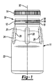
本開示の再密閉可能な容器及び閉鎖パッケージの実施例は、図1及び図2に示され、また、全般的に参照番号10で表される。例えば1クォート(0.95リットル)、1.5クォート(1.42リットル)、及び0.5ガロン(1.89リットル)サイズの容器を、容器11を形成することができる任意の方法によって形成することができる。容器11を形成することができる方法の一例は、高密度ポリエチレン(HDPE)からの押出ブロー成型である。本明細書で開示される容器の実施例は、ポリプロピレン(PP)またはポリエチレンテレフタル酸塩(PET)を含む他のプラスチックから成型することができる。図1を参照すると、再密閉可能な容器及び閉鎖パッケージ10は、円形断面(図8を参照されたい)である首部12を有する容器11を含む。首部12は、少なくとも50mmの直径の広口を有する。少なくとも60mmの直径も有用であり、特に、70〜100mmまたはそれ以上の直径が想定される。首部12は、閉鎖キャップ14によって密閉することができ、また、閉鎖キャップ14を首部12に対して連続して開口及び閉鎖して、容器11の内部空間内の内容物を分配し効果的に密閉することを可能にするように構成することができる。図1には、閉鎖キャップ14が示され、閉鎖キャップ14の内部空間内に含まれる螺旋ねじ山が首部12のねじ山16に合致する。示されるように、首部12は、隆起した環状首部ビード18を含む。
An example of a resealable container and closure package of the present disclosure is shown in FIGS. 1 and 2 and is generally designated by the
首部12から延在して、容器11は、首部12よりも大きい直径である肩部20を含む。実施例において、肩部20は、全体を通して円形断面を有することができる。しかしながら、本開示の他の実施例では、他の断面形状も可能であり、例えば、楕円断面、長方形断面、及び正方形断面も本明細書で開示される。円形断面を維持することによって、本開示の容器を、既存の塗料缶取り扱い機器により容易に嵌合させることができると考えられる。
Extending from the
図1に表される実施例において、肩部20は、首部12から漸進的に拡大する。図3及び図5に表される実施例に示されるように、肩部の他の実施例を提供することができる。肩部20の下側は、容器11の円筒本体22である。本体22は、均一な外壁を有し、また、ほぼ全体にわって円形断面を有することができる。肩部20と同様に、本体22には、円形断面以外を提供することができる。
In the embodiment depicted in FIG. 1, the
参照番号24によって示される容器11の握り部分は、複数の円周方向に離間配置されたリブ26を含み、これらのリブは、プラスチック容器11の強度を増加させ、また、容器11を従来の塗料混合機器で使用することを可能にし、それでも、そのような機器での激しい振盪中に、容器11の完全性を維持する。リブ26は、図1に示されるように、容器11の内部空間に向かって延在する凹みである。リブ26は、図1に示されるような凹み、または図3においてリブ26’によって示されるような外面からの突出部の形態とすることができることを理解されたい。
The grip portion of the
容器11は、別々に成型するか、または別々に形成し、その後に、容器11に加える必要がある、いかなるハンドルアクセサリも含まない。更に、本開示の容器11は、容器11から横方向に延在または突出する、いかなるハンドル構成も含まない。したがって、容器11の金型は、比較的単純な構造であり、また、均一な厚さを獲得し易い比較的容易な成型を可能にする。
The
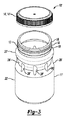
図3は、本開示による、再密閉可能な容器及び閉鎖パッケージ10’の別の実施例の分解斜視図である。図3に示されるプラスチック容器11’は、例えば、1クォート(0.95リットル)、1.5クォート(1.42リットル)、及び0.5ガロン(1.89リットル)サイズに製作することができる。容器11’は、上で説明される容器11を形成するために使用されるように、プラスチック材料から押出ブロー成型によって形成することができる。容器11’は、円形断面(図8を参照されたい)である首部12を含む。図4に表される首部12は、図1に表される首部12と同一である。このように、首部12は、同じく図1に表される閉鎖キャップ14と同一である閉鎖キャップ14によって密閉することができ、また、閉鎖キャップ14を首部12に対して連続して開口及び閉鎖して、容器11’の内部空間内の内容物を分配し効果的に密閉することを可能にするように構成することができる。図3に表されるように、首部12は、閉鎖キャップ14の内部空間に含まれるねじ山に合致する、螺旋ねじ山16を含む。首部12も同様に、図1に表される隆起した環状首部ビード18と同一である、隆起した環状首部ビード18を含む。
FIG. 3 is an exploded perspective view of another embodiment of a resealable container and closure package 10 'according to the present disclosure. The
首部12の下側で、容器11’は、首部12よりも大きい直径である肩部20を含む。肩部20’は、好ましくは、全体を通して円形断面を有する。容器11’と図1の容器11との特定の違いは、肩部20’の形状である。肩部20’は、容器11の肩部20と比較して肩部20’よりも小さい直径を有する握り部分24’と最終的に融合する、丸みのある形状であり、該形状は、首部から握り部分24まで拡大し、本体部分22と融合するまで拡大し続ける。
Below the
円周握り部分24’は、容器11’の周りの円周凹みの形態で、肩部20’と本体22’との間に位置付けられる。握り部分24’は、肩部20’及び本体22’の双方の外径よりも小さい外径を有し、ユーザが、容器11’を片手で、典型的には手の親指と人差し指との間で保持することを可能にする。図1に表される容器11と同様に、図3に表される容器11’は、別々に成型するか、または別々に形成し、その後に、容器に加える必要がある、ハンドルアクセサリを含まない。更に、本開示の容器11’は、容器11’から横方向に延在または突出する、いかなるハンドル構成も含まない。したがって、容器11’の金型は、比較的単純な構造であり、また、均一な厚さを獲得し易い比較的簡単な成型を可能にする。細い直径の握り部分24’は、頂部から底部まで本開示の容器11’の円形断面を維持し、また、本開示の容器11’を、従来の塗料缶取り扱い及び振盪機器で利用することを可能にする。
A circumferential grip portion 24 'is positioned between the shoulder 20' and the body 22 'in the form of a circumferential recess around the container 11'. The grip portion 24 'has an outer diameter that is smaller than the outer diameter of both the shoulder 20' and the body 22 'so that the user can hold the container 11' with one hand, typically between the thumb and index finger of the hand. Makes it possible to hold on. Similar to the
容器11’をある程度強化するために、握り部分24’は、握り部分24’に沿って円周方向に離間され、該握り部分の中へ成型される、複数の垂直リブ26’を含む。リブ26’は、図3に示されるように外面からの突出部とすることができ、または図1及び図5にそれぞれ例示される容器11、11’’に示されるような凹みとすることができる。リブ26’は、容器11’の強度を高め、また特に、従来の塗料混合機器で行われる激しい振盪に耐える強度を提供する。
In order to strengthen the container 11 'to some extent, the grip portion 24' includes a plurality of vertical ribs 26 'spaced circumferentially along the grip portion 24' and molded into the grip portion. The rib 26 'can be a protrusion from the outer surface as shown in FIG. 3, or it can be a recess as shown in the
肩部20’の下側は、容器11’の円筒本体22’である。本体22’は、均一な外壁、及びほぼ全体にわたる円形断面を有する。本体22’には、円形断面以外を提供することができる。 Below the shoulder 20 'is a cylindrical body 22' of the container 11 '. The body 22 'has a uniform outer wall and a substantially circular cross section. The body 22 'can be provided with other than a circular cross section.
図4は、図1に表される再密閉可能な容器及び閉鎖パッケージ10の実施例の分解斜視図である。
4 is an exploded perspective view of the embodiment of the resealable container and
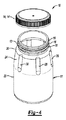
図5は、本開示による、再密閉可能な容器及び閉鎖パッケージ10’’の更なる一実施例の分解斜視図である。図5には、本開示のプラスチック容器11’’の更に別の実施例が示される。プラスチック容器11’’は、容器11及び11’と同じプラスチック材料で形成することができる。ここでも、容器11’’は、任意の適切な成型技法によって形成することができる。図5に表される首部12は、図1に表される首部12と同一である。このように、首部12は、同じく図1に表される閉鎖キャップ14と同一である閉鎖キャップ14によって密閉することができ、また、閉鎖キャップ14を首部12に対して連続して開口及び閉鎖して、容器11’’の内部空間内の内容物を分配し効果的に密閉することを可能にすることができる。図5に表されるように、首部12は、閉鎖キャップ14の内部空間に形成されるねじ山に合致する、螺旋ねじ山16を含む。首部12も同様に、図1に表される隆起した環状首部ビード18と同一である、隆起した環状首部ビードを含む。
FIG. 5 is an exploded perspective view of a further embodiment of a resealable container and closure package 10 '' according to the present disclosure. FIG. 5 shows yet another embodiment of the
図5に表される容器11’’の握り部分24’’は、図3に表される容器11’のように、円周の窪んだリングによって形成されない。しかしながら、容器11’’の握り部分24’’は、複数の円周方向に離間配置されたリブ26’’を含み、これらのリブは、プラスチック容器11’’の強度を増加させ、また、容器11’’を既存の塗料混合機器で使用することを可能にし、それでも、そのような機器での激しい振盪中に、容器11’’の完全性を維持する。リブ26’’は、図5に示されるように、凹みであり、または、換言すれば、容器11’’の内部空間に向かって延在する。リブ26’’は、図1に示されるような凹み、または図3においてリブ26’によって示されるような外面からの突出部の形態とすることができることを理解されたい。
The
握り部分24’’の下側は、本体部分22’’である。本体部分22’’は、均一な外壁、及びほぼ全体にわたる円形断面を有することができる。同様に、握り部分24’’及び首部12は、円形断面を有することができる。容器11’’の握り部分24’’は、首部12から本体部分22’’まで拡大させることができる。
The lower side of the
図6は、本開示の容器11、11’、11’’の一実施例の首部仕上げ部分30の側面図である。図7は、図6に示される実施例の首部仕上げ部分のねじ山プロファイルの詳細を表す拡大側面図である。再密閉可能な容器及び閉鎖パッケージ10、10’、10’’(図1、図3、及び図5)は、容器11、11’、11’’及び閉鎖キャップ14、14’を含む。容器11、11’、11’’は、容器11、11’、11’’の首部12に形成される長手方向中心軸32及び仕上げ部分30を含む。仕上げ部分30は、仕上げ部分30に確立される、一条螺旋雄ねじ構成16を含む。雄ねじ構成16は、約1.5回転の連続するねじ山の完全なねじ山プロファイル34を含む。完全なねじ山プロファイル34は、約13度の対称的な雄ねじフランク角36を有する。
FIG. 6 is a side view of the
本明細書で使用するときに、用語「フランク角」は、軸平面において測定される個々のフランクと中心軸32に対して垂直な面との間の角度を意味する。本明細書で使用するときに、用語「フランク」は、ねじ山の頂上と谷底とを接続するいずれかの表面を意味する。本明細書で使用するときに、用語「頂上」は、ねじ山のフランクにつながり、ねじ山が突出する円筒から最も遠くにある表面を意味する。雄ねじの頂上は、雄ねじの大径にあり、一方で、雌ねじの頂上は、雌ねじの小径にある。本明細書で使用するときに、用語「谷底」は、2つの隣接するねじ山のフランクにつながる表面を意味する。本明細書で使用するときに、完全なねじ山プロファイル34は、頂上及び谷底の完全な形態を有するねじ山プロファイルである。完全なねじ山プロファイル34は、ねじ山に沿ってほぼ一定である。完全なプロファイルは、導入部分を含まない。ねじ山は、全くねじ山のない状態(すなわち、螺入物体のねじなし部分)から完全に発達したねじ山までねじ山プロファイルが漸進的に変化する、導入部分を有することができる。ねじ山のそのような導入部分は、ねじ山と噛合部品の噛合ねじ山との位置合わせをより容易に行うことができる。
As used herein, the term “flank angle” means the angle between an individual flank measured in the axial plane and a plane perpendicular to the
更に図6及び図7を参照すると、仕上げ部分30は更に、中心軸32に対して直角の平面44から約0度〜約5度の角度42で、首部12の内径40から半径方向内向きに延在する弾性環状リップ38を含む。仕上げ部分30はなお更に、弾性環状リップ38の外面48に配置される、密閉面46を含む。
With further reference to FIGS. 6 and 7, the
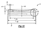
隆起した環状首部ビード18は、環状リップ38の遠位にある、首部12の外面56に配置される。隆起した環状首部ビード18の円錐台形面64は、環状リップ38からの距離が増加するにつれて、直径が増加する。隆起した環状首部ビード18の円筒面66は、円錐台形面64の最大直径68で画定される。環状リップ38の遠位にある円筒面66の縁部70は、長手方向中心軸32に対して垂直な仕上げ底部平面72を画定する。
The raised
雄ねじ構成16は、88.73(mm)ミリメートル〜89.63mmの大径Tを有する。雄ねじ構成16は、85.68mm〜86.58mmの小径Eを有する。首部12は、73.66mmの最小内径Iを有する。
The
環状リップ38の頂縁部92は、再密閉可能な容器及び閉鎖パッケージ10、10’、10’’の密閉容積94の遠位にある。環状リップ38の頂縁部92は、小径Eよりも7.62mm小さい、内側リップ直径96を画定する。環状リップ38の頂縁部92と雄ねじ構成16との間の最短距離Sは、3.23mm〜3.99mmである。環状リップ38の頂縁部92と、円錐台形面64と長手方向中心軸32と同軸な直径87.89mm〜88.39mmの円筒との交差点で測定した隆起した環状首部ビード18の円錐台形面64との最短距離Hは、15.06mm〜15.82mmである。円錐台形面の最大直径68は、89.92mm〜90.42mmである。環状リップ38の頂縁部92と仕上げ底部平面72との間の垂直距離H2は、16.32mm〜17.08mmである。
The top edge 92 of the
パッケージ10、10’、10’’は更に、閉鎖キャップ14、14’を含む。図8〜図12は、本開示による、閉鎖キャップ14の一実施例を表す。本開示の実施例において、閉鎖キャップ14は、耐衝撃性コポリマーから成型することができる。本開示の耐衝撃性コポリマーの一例は、1パーセントのKemamide(登録商標)E(Chemtura Corp.,本社Philadelphia、PAから入手可能)を有するPinnacle PP 3220ポリプロピレン衝撃コポリマー(Pinnacle Polymers、Garyville、LAから入手可能)である。耐衝撃性コポリマーは、本開示の再密閉可能な容器及び閉鎖パッケージの優れた落下試験性能に寄与すると考えられる。閉鎖キャップ14は、円周縁部52を画定する端部壁50を含む。閉鎖キャップ14は、端部壁50から突出する環状スカート54を有する。隆起した環状キャップビード74は、閉鎖キャップ14に配置されて、閉鎖キャップ14が容器11、11’、11’’に設置されたときに密閉面46に密閉係合する。雌ねじ60は、環状スカート54の内面62に画定される。雌ねじ60は、雄ねじ構成16とねじ係合可能である(図13を参照されたい)。雌ねじ60は、SP400フィニッシュ用の「M」字状の断面を有する(ASTM D2911−10を参照されたい)。しかしながら、SP400フィニッシュと噛合する「M」字状の断面が使用されているが、本開示の容器は、SP400フィニッシュを有しないことを理解されたい。更に、標準仕上げと噛合させるには標準キャップが選択されるので、このキャップは標準キャップではない。
The
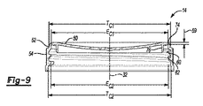
当業界においては、標準首部仕上げ及びキャップの使用が求められている。典型的には、標準首部仕上げが選択され、選択した首部仕上げに合致するように標準キャップが選択される。標準でない閉鎖具を開発するには、ツーリングを設計及び創作し、次いで、容器/キャップの試験を繰り返すことが必要である。容器の市場では価格競争が激しく、したがって、標準部品から逸脱することは極端に高価になると考えられている。それでもなお、本開示の発明者らは、プラスチック容器用のあらゆる既存の閉鎖具及び首部仕上げに勝る特性を有する閉鎖具及び首部仕上げの創作に努めた。図9に示されるように、円周縁部52の外径TC1は、89.20mmである。環状スカート54は、円周縁部52に対向する85.98mmの内壁直径EC1を有する。雌ねじ60は、86.11mmの小径EC2を有する。雌ねじ60は、89.38mmの大径TC2を有する。端部壁の厚さは、1.6mmである。
The industry requires the use of standard neck finishes and caps. Typically, a standard neck finish is selected and a standard cap is selected to match the selected neck finish. Developing non-standard closures requires designing and creating the tooling and then repeating the container / cap test. Price competition in the container market is fierce, and thus deviating from standard parts is considered extremely expensive. Nonetheless, the inventors of the present disclosure have sought to create closures and neck finishes that have properties superior to any existing closures and neck finishes for plastic containers. As shown in FIG. 9, the outer diameter T C1 of the circular peripheral edge 52 is 89.20 mm. The
図8〜図12に表される本開示の実施例において、環状プラグシール76は、端部壁50から中心軸32に対してほぼ平行に延在することができる。環状プラグシール76は、首部12の内径40よりも約0.19インチ(4.83mm)大きい、78.49mmの非応力状態のプラグシール外径78を有することができる。環状プラグシール76は、環状プラグシール76の先端82に外側フィレットまたは面取り80を有することができる。閉鎖キャップ14が容器11、11’、11’’に設置されたときに、環状プラグシール76は、環状リップ38に密閉係合して、環状リップ38との締まり嵌めを形成することができる(図13を参照されたい)。
In the embodiment of the present disclosure represented in FIGS. 8-12, the annular plug seal 76 can extend from the end wall 50 substantially parallel to the
図10は、環状プラグシール76を有する閉鎖キャップ14の更なる寸法を表す。閉鎖キャップ14のねじ付き部分の下側で、環状スカート54は、約93.98mmの外径57及び約89.99mmの内径58を有する、フレア部分55を有する。閉鎖キャップ14は、環状スカート54からの中心軸32に対して平行な最大距離において、頂部平面45を画定する。例示のために、端部壁50がテーブル面(図示せず)に静置された状態で閉鎖キャップ14を配置した場合は、テーブル表面が頂部平面にある。頂部平面45と雌ねじ60の任意の部分との間の最短距離47は、4.85mmである。環状プラグシール76の壁厚49は、1.19mmである。
FIG. 10 represents a further dimension of the
図11は、より詳細に示される、閉鎖キャップ14の拡大断面図である。環状プラグシール76は、90.6度の内部抜き勾配61及び90.5度の外部抜き勾配63を有する。隆起した環状キャップビード74の端部壁からの突出距離65は、0.74mmである。閉鎖キャップ14は、端部壁50からの中心軸32に対して平行な最大距離において、底部平面51を画定する。例示のために、環状スカート54のフレア部分55がテーブル面(図示せず)に静置された状態で閉鎖キャップ14を配置した場合は、テーブル表面が底部平面51にある。内部面取り79は、閉鎖キャップの底部平面51と44.5度の内部面取り角81をなして表される。内部面取り幅83は、0.91mmであり、底部平面51上への突出として測定される。
FIG. 11 is an enlarged cross-sectional view of the
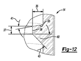
図12は、雌ねじのねじ山プロファイルの詳細を表す。ねじピッチは、0.2インチ(5.08mm)である。先行フランク角43は、45度である。後続フランク角41は、10度である。本明細書で使用するときに、「先行フランク」は、ねじ山と噛合ねじ山とを組み立てようとしているときに、噛合ねじ山に面するねじ山のフランクを意味する。後続フランクは、先行フランクの反対側である。雌ねじ頂上39は、1.19mmの雌ねじ頂上幅37を有する。雌ねじ高さ35は、1.63mmである。
FIG. 12 shows details of the thread profile of the internal thread. The screw pitch is 0.2 inches (5.08 mm). The leading
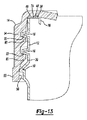
図13は、閉鎖キャップ14及び容器11、11’、11’’の係合の詳細を表す、再密閉可能な容器及び閉鎖パッケージ10、10’、10’’の一部分の拡大側断面図である。雌ねじ60は、後続フランク33において雄ねじ16に係合する。隆起した環状首部ビード18は、環状スカート54のフレア部分55と接触し、該フレア部分を支持する。隆起した環状首部ビード18による環状スカート54のフレア部分55の支持は、衝撃中の閉鎖キャップ14の歪みに抵抗するのを補助し、また、本開示の優れた耐漏出性に寄与する。隆起した環状キャップビード74は、弾性環状リップ38を僅かに偏向させ、弾性環状リップ38の外面48に配置される密閉面46に密閉係合する。環状プラグシール76は、環状リップ38に密閉係合し、環状リップ38との締まり嵌めを形成する。
FIG. 13 is an enlarged side cross-sectional view of a portion of the resealable container and
図14に表される本開示の実施例において、閉鎖キャップ14’にはプラグシールが含まれない。図14に表される実施例は、閉鎖キャップ14’が容器11、11’、11’’に設置されたときに、閉鎖キャップ14’の端部壁50の内面86と接触して保持されて、閉鎖キャップ14’と容器との間に密閉ガスケット88を形成する、ライナーディスク84を含む。閉鎖キャップ14’が容器11、11’、11’’から分離されたときに、ライナーディスク84を保持するために、環状スカート54の内面62には複数のライナー保持ラグ90が画定される。ライナーディスク84は、接着剤(図示せず)によって環状スカート54の内面62に貼付することができる。ライナーディスク84は、コーティング発泡ライナーディスクとすることができる。一実施例において、ライナーディスク84は、約0.64mmの厚さを有することができる。一実施例において、ライナーディスク84は、ライナー材料のシートを共押し出し加工し、該シートからライナーディスクを切り取ることによって形成することができる。
In the embodiment of the present disclosure depicted in FIG. 14, the closure cap 14 'does not include a plug seal. The embodiment depicted in FIG. 14 is held in contact with the inner surface 86 of the end wall 50 of the
本開示の実施例において、閉鎖キャップ14、14’を容器11に設置した状態での再密閉可能な容器及び閉鎖パッケージ10の内部容積98は、約1.5クォート(1.42リットル)である。本明細書で使用するときに、再密閉可能な容器及び閉鎖パッケージ10、10’、10’’の内部容積98は、ASTM D2911−10「プラスチック瓶に関する寸法及び許容差の標準仕様」(Standard Specification for Dimensions and Tolerances for Plastic Bottles)の8.1節の「ボトル容量」(Bottle Capacity)、または同等物によって決定される、「ボトル容量」を意味する。
In an embodiment of the present disclosure, the internal volume 98 of the resealable container and
他の実施例において、閉鎖キャップ14、14’を容器11’に設置した状態での再密閉可能な容器及び閉鎖パッケージ10’の内部容積98は、約1クォート(0.95リットル)である。更に他の実施形態において、閉鎖キャップ14、14’を容器11’’に設置した状態での再密閉可能な容器及び閉鎖パッケージ10’’の内部容積98は、約0.5ガロン(1.89リットル)である。
In another embodiment, the internal volume 98 of the resealable container and closure package 10 'with the closure caps 14, 14' installed in the container 11 'is about 1 quart (0.95 liter). In yet another embodiment, the internal volume 98 of the resealable container and
閉鎖キャップ14、14’を容器11、11’、11’’に設置した状態で、再密閉可能な容器及び閉鎖パッケージ10、10’、10’’は、容器の底部を12フィートの高さから滑らかな中実のコンクリート床に衝突させる落下試験の後に、いかなる可視的な水漏れも生じない。
With the closure caps 14, 14 ′ installed in the
本開示の実施例において、閉鎖キャップ14、14’を容器11、11’、11’’に最初に設置した後に標本に対して行われる落下試験と、その後の、閉鎖キャップ14、14’を容器に3回目に設置した後に同じ標本に対して行われる落下試験との間で、標本の密閉性能にいかなる低下も伴わずに、閉鎖キャップ14、14’を、再密閉可能な容器及び閉鎖パッケージ10、10’、10’’の標本に関して、少なくとも3回、容器11、11’、11’’に対して取り外し可能かつ再設置可能である。
In an embodiment of the present disclosure, a drop test is performed on the specimen after the closure caps 14, 14 ′ are first installed in the
閉鎖キャップ14、14’は、閉鎖キャップ14、14’の部分間の脆弱接続部に打ち勝つことなく、閉鎖キャップ14、14’の容器11、11’、11’’への最初の設置後に、容器11、11’、11’’から取り外すことができる。
The closure caps 14, 14 ′ can be used after the first installation of the closure caps 14, 14 ′ in the
単語「a」及び「an」、並びに他の単数形の指示語の使用は、別途文脈上明らかに指示のある場合を除き、明細書及び特許請求の範囲の双方において、複数形を含む場合があることを理解されたい。 The use of the words “a” and “an” and other singular forms may include the plural in both the specification and the claims, unless the context clearly indicates otherwise. I want you to understand.
本明細書に提供される範囲は、提示された範囲、及び提示された範囲内の任意の値またはサブ範囲を含むことを理解されたい。例えば、約0度〜約5度という範囲は、約0度〜約5度の明示的に記載された範囲だけでなく、1度、1.2度、2.5度、4.0度などの別個の値、及び約1.5度〜約4.5度、約2.0度〜約3.0度などのサブ範囲も含むものと解釈されたい。更に、値を記載するために「約」を利用したときには、提示された値からの僅かな変動(最大±10%)を包含することを意味する。 It is to be understood that the ranges provided herein include the presented range and any value or sub-range within the presented range. For example, the range of about 0 degrees to about 5 degrees is not only the explicitly described range of about 0 degrees to about 5 degrees, but also 1 degree, 1.2 degrees, 2.5 degrees, 4.0 degrees, etc. As well as sub-ranges such as about 1.5 degrees to about 4.5 degrees, about 2.0 degrees to about 3.0 degrees, and the like. Further, when “about” is used to describe a value, it is meant to encompass slight variations (up to ± 10%) from the value presented.
更に、明細書全体を通しての「ある実施例」、「別の実施例」、「一実施例」などの記述は、実施例に関連して記載される特定の要素(例えば、特徴、構造、及び/または特性)が、本明細書に記載される少なくとも1つの実施例に含まれ、他の実施例に存在する場合もあれば、存在しない場合もあることを意味する。加えて、任意の実施例について記載された要素は、別途文脈が明確に指示しない限り、様々な実施例において任意の適切な様式で組み合わせられ得ることを理解されたい。 Further, throughout the specification, descriptions such as “one embodiment,” “another embodiment,” “one embodiment,” and the like refer to particular elements (eg, features, structures, and Is included in at least one embodiment described herein and may or may not be present in other embodiments. In addition, it should be understood that elements described for any embodiment may be combined in any suitable manner in the various embodiments, unless the context clearly indicates otherwise.
いくつかの実施例が詳細に記載されているが、開示された実施例は、修正され得ることが当業者に明らかになるであろう。したがって、上の説明は、限定的なものとみなすべきではない。 While several embodiments have been described in detail, it will be apparent to those skilled in the art that the disclosed embodiments can be modified. Accordingly, the above description should not be taken as limiting.
Claims (12)
容器であって
長手方向中心軸、と
前記容器の首部に形成される仕上げ部分であって、
前記仕上げ部分に確立される一条螺旋雄ねじ構成であって、前記雄ねじ構成が、前記約1.5回転の連続するねじ山の完全なねじ山プロファイルを含み、前記完全なねじ山プロファイルが、約13度の対称的な雄ねじフランク角を有する、一条螺旋雄ねじ構成と、
前記中心軸に対して直角の平面から約0度〜約5度の角度で、前記首部の内径から半径方向内向きに延在する弾性環状リップと、
前記環状リップの外面に配置される密閉面と、を含む、仕上げ部分と、を含む、容器と、
閉鎖キャップであって、
円周縁部を画定する端部壁と、
前記端部壁から突出する環状スカートと、
前記環状スカートの内面に画定される雌ねじと、を含み、
前記雌ねじが、前記雄ねじ構成とねじ係合可能であり、
前記雌ねじが、SP400フィニッシュ用の「M」字状の断面を有する、閉鎖キャップと、
を備える、前記再密閉可能な容器及び閉鎖パッケージ。 A resealable container and a closed package,
A container, a longitudinal central axis, and a finishing portion formed on a neck of the container,
A single spiral male thread configuration established in the finished portion, wherein the male thread configuration includes a complete thread profile of the continuous thread of about 1.5 turns, wherein the complete thread profile is about 13 A single spiral male thread configuration having a symmetrical male thread flank angle of degrees;
An elastic annular lip extending radially inward from the inner diameter of the neck at an angle of about 0 to about 5 degrees from a plane perpendicular to the central axis;
A container including a sealing portion disposed on an outer surface of the annular lip, and a finishing portion.
A closure cap,
An end wall defining a circumferential edge;
An annular skirt protruding from the end wall;
An internal thread defined on the inner surface of the annular skirt,
The female thread is threadably engageable with the male thread configuration;
A closure cap, wherein the internal thread has an "M" shaped cross section for SP400 finish;
Said resealable container and closed package.
前記環状リップからの距離が増加するにつれて直径が増加する、前記隆起した環状首部ビードの円錐台形状表面と、
前記円錐台形面の最大直径の場所に画定される、前記隆起した環状首部ビードの円筒面と、
前記長手方向中心軸に対して垂直な仕上げ底部平面を画定する、環状リップの遠位にある前記円筒面の縁部と、を更に備える、請求項1に記載の前記再密閉可能な容器及び閉鎖パッケージ。 A raised annular neck bead disposed on the outer surface of the neck distal to the tubular lip;
A frustoconical surface of the raised annular neck bead that increases in diameter as the distance from the annular lip increases;
A cylindrical surface of the raised annular neck bead defined at a maximum diameter location of the frustoconical surface;
The resealable container and closure of claim 1, further comprising an edge of the cylindrical surface distal to the annular lip that defines a finished bottom plane perpendicular to the longitudinal central axis. package.
前記環状プラグシールが、前記首部の前記内径よりも約0.19インチ大きい、非応力状態のプラグシール外径を有し、
前記環状プラグシールが、前記環状プラグシールの先端に外側フィレットまたは面取りを有し、
前記閉鎖キャップが前記容器に設置されたときに、前記環状プラグシールが、前記環状リップに密閉係合して、前記環状リップとの締まり嵌めを形成する、請求項3に記載の前記再密閉可能な容器及び閉鎖パッケージ。 An annular plug seal extending substantially parallel to the central axis from the end wall;
The annular plug seal has an unstressed plug seal outer diameter that is about 0.19 inches greater than the inner diameter of the neck;
The annular plug seal has an outer fillet or chamfer at the tip of the annular plug seal;
The resealable claim of claim 3, wherein the annular plug seal is in sealing engagement with the annular lip to form an interference fit with the annular lip when the closure cap is installed in the container. Container and closed package.
前記閉鎖キャップが前記容器から分離されたときに、前記ライナーディスクを保持するために前記環状スカートの前記内面に画定される、複数のライナー保持ラグと、を更に備える、請求項1に記載の前記再密閉可能な容器及び閉鎖パッケージ。 A liner that is held in contact with the inner surface of the end wall of the closure cap so as to form a sealing gasket between the closure cap and the container when the closure cap is installed in the container. A disc,
The liner of claim 1, further comprising a plurality of liner retaining lugs defined on the inner surface of the annular skirt to retain the liner disk when the closure cap is separated from the container. Resealable container and closed package.
前記雄ねじ構成が、85.68mm〜86.58mmの小径を有し、
前記首部が、73.66mmの最小内径を有し、
前記環状リップの頂縁部が、前記再密閉可能な容器及び閉鎖パッケージの密閉容積の遠位にあり、前記環状リップの前記頂縁部が、前記小径よりも7.62mm小さい内側リップ直径を画定し、
前記環状リップの前記頂縁部と前記雄ねじ構成との間の最短距離が、3.23mm〜3.99mmであり、
前記環状リップの前記頂縁部と、87.89mm〜88.39mmのビード表面直径で測定した前記隆起した環状首部ビードの前記円錐台形面との間の最短距離が、15.06mm〜15.82mmであり、
前記円錐台形面の最大直径が、89.92mm〜90.42mmであり、
前記環状リップの前記頂縁部と前記仕上げ底部平面との間の垂直距離が、16.32mm〜17.08mmである、請求項1に記載の前記再密閉可能な容器及び閉鎖パッケージ。 The male thread configuration has a large diameter of 88.73 (mm) millimeters to 89.63 mm;
The male thread configuration has a small diameter of 85.68 mm to 86.58 mm;
The neck has a minimum inner diameter of 73.66 mm;
The top edge of the annular lip is distal to the sealed volume of the resealable container and the closed package, and the top edge of the annular lip defines an inner lip diameter that is 7.62 mm less than the small diameter. And
The shortest distance between the top edge of the annular lip and the male thread configuration is 3.23 mm to 3.99 mm;
The shortest distance between the top edge of the annular lip and the frustoconical surface of the raised annular neck bead measured at a bead surface diameter of 87.89 mm to 88.39 mm is 15.06 mm to 15.82 mm. And
The frustoconical surface has a maximum diameter of 89.92 mm to 90.42 mm;
The resealable container and closure package of claim 1, wherein the vertical distance between the top edge of the annular lip and the finished bottom plane is 16.32 mm to 17.08 mm.
Applications Claiming Priority (3)
| Application Number | Priority Date | Filing Date | Title |
|---|---|---|---|
| US14/224,589 | 2014-03-25 | ||
| US14/224,589 US9254941B2 (en) | 2014-03-25 | 2014-03-25 | Resealable container and closure package |
| PCT/US2015/022314 WO2015148555A1 (en) | 2014-03-25 | 2015-03-24 | Resealable container and closure package |
Publications (2)
| Publication Number | Publication Date |
|---|---|
| JP2017512723A true JP2017512723A (en) | 2017-05-25 |
| JP2017512723A5 JP2017512723A5 (en) | 2019-07-04 |
Family
ID=54189298
Family Applications (1)
| Application Number | Title | Priority Date | Filing Date |
|---|---|---|---|
| JP2016558600A Ceased JP2017512723A (en) | 2014-03-25 | 2015-03-24 | Resealable container and closed package |
Country Status (7)
| Country | Link |
|---|---|
| US (1) | US9254941B2 (en) |
| EP (1) | EP3122645A4 (en) |
| JP (1) | JP2017512723A (en) |
| KR (1) | KR20160138123A (en) |
| CN (1) | CN106103295B (en) |
| BR (1) | BR112016021843A2 (en) |
| WO (1) | WO2015148555A1 (en) |
Cited By (1)
| Publication number | Priority date | Publication date | Assignee | Title |
|---|---|---|---|---|
| JP2021155107A (en) * | 2020-03-30 | 2021-10-07 | 日本山村硝子株式会社 | Resin cap |
Families Citing this family (12)
| Publication number | Priority date | Publication date | Assignee | Title |
|---|---|---|---|---|
| KR20150110528A (en) * | 2013-01-25 | 2015-10-02 | 도칸 고교 가부시키가이샤 | Container sealing device |
| US11136167B2 (en) | 2014-06-26 | 2021-10-05 | Plastipak Packaging, Inc. | Plastic container with threaded neck finish |
| AU2015279687A1 (en) * | 2014-06-26 | 2017-02-02 | Plastipak Packaging, Inc. | Plastic container with threaded neck finish |
| CH710295A1 (en) * | 2014-10-29 | 2016-04-29 | Alpla Werke Alwin Lehner Gmbh & Co Kg | Stretch blow molded plastic containers, especially plastic bottles, to compensate for changes in volume of the medium. |
| US11577877B2 (en) | 2016-10-21 | 2023-02-14 | Amcor Rigid Packaging Usa, Llc | Lightweight polymeric container finish |
| BR112018007218B1 (en) * | 2016-10-21 | 2022-08-02 | Amcor Rigid Plastics Usa, Llc | POLYMERIC CONTAINER |
| US11577876B2 (en) | 2016-10-21 | 2023-02-14 | Amcor Rigid Packaging Usa, Llc | Lightweight polymeric container finish |
| US11708188B2 (en) | 2016-10-21 | 2023-07-25 | Amcor Rigid Packaging Usa, Llc | Lightweight polymeric container finish |
| US11578296B2 (en) * | 2016-11-30 | 2023-02-14 | Corning Incorporated | Reinforced barbed closure |
| US20190062007A1 (en) * | 2017-08-31 | 2019-02-28 | Silgan White Cap LLC | Closure With Angled Plug Seal |
| CN113967708B (en) * | 2021-11-26 | 2024-06-18 | 广东欧亚包装有限公司 | ROPP screw ware |
| IT202200021171A1 (en) * | 2022-10-14 | 2024-04-14 | Giflor S R L | PLASTIC CONTAINER |
Citations (8)
| Publication number | Priority date | Publication date | Assignee | Title |
|---|---|---|---|---|
| JPS5254355U (en) * | 1975-10-15 | 1977-04-19 | ||
| US4798303A (en) * | 1987-04-15 | 1989-01-17 | Chesebrough-Pond's Inc. | Continuous thread closure assembly |
| US5213224A (en) * | 1990-08-09 | 1993-05-25 | Portola Packaging, Inc. | Snap-on, screw-off cap and container neck |
| JPH08113258A (en) * | 1994-10-17 | 1996-05-07 | Shibasaki Seisakusho:Kk | Synthetic resin cap |
| US5553727A (en) * | 1995-04-27 | 1996-09-10 | Consumer Cap Corporation | Tamper-evident cap and neck finish |
| JP2007530377A (en) * | 2004-03-27 | 2007-11-01 | エンゲルハード・コーポレーシヨン | container |
| US20080169262A1 (en) * | 2007-01-12 | 2008-07-17 | Phoenix Closures, Inc. | Closure with ring ribs |
| JP2009502676A (en) * | 2005-07-26 | 2009-01-29 | レクサム プリスクリプション プロダクツ インコーポレイテッド | Package that can be converted to child resistant closure and non-child resistant operation |
Family Cites Families (19)
| Publication number | Priority date | Publication date | Assignee | Title |
|---|---|---|---|---|
| GB1172608A (en) * | 1967-11-01 | 1969-12-03 | Design Link | Improvements in screw-threaded bottle closures. |
| GB2189228A (en) * | 1986-04-18 | 1987-10-21 | John Stewart Hamilton | Screw threaded aseptic closure |
| US5127784A (en) | 1989-04-19 | 1992-07-07 | Halliburton Company | Fatigue-resistant buttress thread |
| US5667089A (en) * | 1994-03-23 | 1997-09-16 | Phoenix Closures, Inc. | Closure having a wrap-around seal |
| JPH10119997A (en) | 1996-10-21 | 1998-05-12 | House Foods Corp | Screw cap, container, and connection structure thereof |
| US5950849A (en) | 1997-05-12 | 1999-09-14 | Phoenix Closures, Inc. | Container closure with ribbed enlarged grasping region |
| US20050029219A1 (en) * | 1999-11-08 | 2005-02-10 | White Cap, Inc. | Closure for thin-walled containers having a multi-lead threaded neck |
| US7168581B2 (en) * | 2001-12-21 | 2007-01-30 | Rexam Medical Packaging Inc. | Closure for a retort processed container having a peelable seal |
| US7431168B2 (en) * | 2001-12-21 | 2008-10-07 | Rexam Medical Packaging Inc. | Closure for a retort processed container having a peelable seal |
| KR100553806B1 (en) | 2002-09-27 | 2006-02-22 | 가부시키가이샤 니프코 | Bottle-shaped container cap |
| US8002133B2 (en) | 2004-03-27 | 2011-08-23 | Basf Corporation | Colorant container |
| US7694835B1 (en) | 2005-01-04 | 2010-04-13 | Rexam Closures And Containers Inc. | Drafted neck finish having angled thread face and closure package |
| US7651004B2 (en) | 2005-05-12 | 2010-01-26 | Rexam Closure Systems Inc. | Linerless closure and package |
| FR2899567B1 (en) * | 2006-04-07 | 2010-08-13 | Eaux Minerales D Evian Saeme S | CLOSURE SYSTEM FOR CONTAINER |
| US7735664B1 (en) | 2006-04-18 | 2010-06-15 | Portola Packaging, Inc. | Tapered thread structure |
| JP5170619B2 (en) * | 2007-05-11 | 2013-03-27 | ユニバーサル製缶株式会社 | Plastic cap and bottle with cap |
| ES2548289T3 (en) | 2007-06-05 | 2015-10-15 | Tetra Laval Holdings & Finance S.A. | Closure for a container of a pourable food product and method of production thereof |
| US8308005B2 (en) | 2008-01-30 | 2012-11-13 | Amcor Limited | Preform and container having debossed support flange |
| DE102008014952A1 (en) | 2008-03-19 | 2009-09-24 | Z-Werkzeugbau-Gmbh | screw cap |
-
2014
- 2014-03-25 US US14/224,589 patent/US9254941B2/en active Active
-
2015
- 2015-03-24 EP EP15768989.4A patent/EP3122645A4/en not_active Withdrawn
- 2015-03-24 JP JP2016558600A patent/JP2017512723A/en not_active Ceased
- 2015-03-24 WO PCT/US2015/022314 patent/WO2015148555A1/en active Application Filing
- 2015-03-24 CN CN201580015705.3A patent/CN106103295B/en not_active Expired - Fee Related
- 2015-03-24 BR BR112016021843A patent/BR112016021843A2/en not_active Application Discontinuation
- 2015-03-24 KR KR1020167028597A patent/KR20160138123A/en not_active Application Discontinuation
Patent Citations (9)
| Publication number | Priority date | Publication date | Assignee | Title |
|---|---|---|---|---|
| JPS5254355U (en) * | 1975-10-15 | 1977-04-19 | ||
| US4798303A (en) * | 1987-04-15 | 1989-01-17 | Chesebrough-Pond's Inc. | Continuous thread closure assembly |
| US5213224A (en) * | 1990-08-09 | 1993-05-25 | Portola Packaging, Inc. | Snap-on, screw-off cap and container neck |
| JPH08113258A (en) * | 1994-10-17 | 1996-05-07 | Shibasaki Seisakusho:Kk | Synthetic resin cap |
| US5553727A (en) * | 1995-04-27 | 1996-09-10 | Consumer Cap Corporation | Tamper-evident cap and neck finish |
| US5553727C1 (en) * | 1995-04-27 | 2001-09-04 | Rical Sa | Tamper-evident cap and neck finish |
| JP2007530377A (en) * | 2004-03-27 | 2007-11-01 | エンゲルハード・コーポレーシヨン | container |
| JP2009502676A (en) * | 2005-07-26 | 2009-01-29 | レクサム プリスクリプション プロダクツ インコーポレイテッド | Package that can be converted to child resistant closure and non-child resistant operation |
| US20080169262A1 (en) * | 2007-01-12 | 2008-07-17 | Phoenix Closures, Inc. | Closure with ring ribs |
Cited By (1)
| Publication number | Priority date | Publication date | Assignee | Title |
|---|---|---|---|---|
| JP2021155107A (en) * | 2020-03-30 | 2021-10-07 | 日本山村硝子株式会社 | Resin cap |
Also Published As
| Publication number | Publication date |
|---|---|
| CN106103295A (en) | 2016-11-09 |
| WO2015148555A1 (en) | 2015-10-01 |
| CN106103295B (en) | 2018-07-03 |
| BR112016021843A2 (en) | 2017-08-15 |
| EP3122645A4 (en) | 2017-03-22 |
| KR20160138123A (en) | 2016-12-02 |
| US9254941B2 (en) | 2016-02-09 |
| US20150274378A1 (en) | 2015-10-01 |
| EP3122645A1 (en) | 2017-02-01 |
Similar Documents
| Publication | Publication Date | Title |
|---|---|---|
| JP2017512723A (en) | Resealable container and closed package | |
| US8322913B2 (en) | Method of mixing paint by shaking container | |
| US5238130A (en) | Closure for a container | |
| US8317042B2 (en) | Lightweight container | |
| JPH05506416A (en) | Container and sealing body | |
| EP3112287A1 (en) | Molded plastic body for dispensing liquid | |
| JP6497801B2 (en) | Weighing container | |
| US20180273255A1 (en) | Sealable container arrangement | |
| US3220618A (en) | Metered liquid dispensing closure | |
| MXPA06010978A (en) | Container | |
| US4682704A (en) | Floating cap seal | |
| JP6188229B2 (en) | cap | |
| JP6848360B2 (en) | Sealed spout | |
| US20200062459A1 (en) | Integrally moulded plastic plug ring cap | |
| US20230102427A1 (en) | Caps for paint container lids | |
| JP2011219112A (en) | Sealing structure for screw type cap | |
| GB2605207A (en) | Leakproof closure cap | |
| WO1987006914A1 (en) | Floating cap seal | |
| JP2021107254A (en) | Replacement cap and container | |
| JP2023154928A (en) | Cap, container, container with cap and container with contents stored | |
| JP2023154927A (en) | Cap, container, container with cap and container with contents stored | |
| JP2021133988A (en) | Barrier cap | |
| EP3532392A1 (en) | Plastic container with integrated spout for directional pour |
Legal Events
| Date | Code | Title | Description |
|---|---|---|---|
| A621 | Written request for application examination |
Free format text: JAPANESE INTERMEDIATE CODE: A621 Effective date: 20180319 |
|
| A977 | Report on retrieval |
Free format text: JAPANESE INTERMEDIATE CODE: A971007 Effective date: 20190221 |
|
| A131 | Notification of reasons for refusal |
Free format text: JAPANESE INTERMEDIATE CODE: A131 Effective date: 20190304 |
|
| A524 | Written submission of copy of amendment under article 19 pct |
Free format text: JAPANESE INTERMEDIATE CODE: A524 Effective date: 20190531 |
|
| A131 | Notification of reasons for refusal |
Free format text: JAPANESE INTERMEDIATE CODE: A131 Effective date: 20191105 |
|
| A521 | Request for written amendment filed |
Free format text: JAPANESE INTERMEDIATE CODE: A523 Effective date: 20200205 |
|
| A01 | Written decision to grant a patent or to grant a registration (utility model) |
Free format text: JAPANESE INTERMEDIATE CODE: A01 Effective date: 20200811 |
|
| A045 | Written measure of dismissal of application [lapsed due to lack of payment] |
Free format text: JAPANESE INTERMEDIATE CODE: A045 Effective date: 20201222 |