JP2017512514A - Electronically monitored and portable point-of-care hand hygiene dispenser with security function - Google Patents
Electronically monitored and portable point-of-care hand hygiene dispenser with security function Download PDFInfo
- Publication number
- JP2017512514A JP2017512514A JP2016553314A JP2016553314A JP2017512514A JP 2017512514 A JP2017512514 A JP 2017512514A JP 2016553314 A JP2016553314 A JP 2016553314A JP 2016553314 A JP2016553314 A JP 2016553314A JP 2017512514 A JP2017512514 A JP 2017512514A
- Authority
- JP
- Japan
- Prior art keywords
- dispenser
- point
- care
- hand hygiene
- cover
- Prior art date
- Legal status (The legal status is an assumption and is not a legal conclusion. Google has not performed a legal analysis and makes no representation as to the accuracy of the status listed.)
- Pending
Links
Images


Classifications
-
- E—FIXED CONSTRUCTIONS
- E05—LOCKS; KEYS; WINDOW OR DOOR FITTINGS; SAFES
- E05B—LOCKS; ACCESSORIES THEREFOR; HANDCUFFS
- E05B65/00—Locks or fastenings for special use
- E05B65/006—Locks or fastenings for special use for covers or panels
-
- A—HUMAN NECESSITIES
- A47—FURNITURE; DOMESTIC ARTICLES OR APPLIANCES; COFFEE MILLS; SPICE MILLS; SUCTION CLEANERS IN GENERAL
- A47K—SANITARY EQUIPMENT NOT OTHERWISE PROVIDED FOR; TOILET ACCESSORIES
- A47K5/00—Holders or dispensers for soap, toothpaste, or the like
- A47K5/06—Dispensers for soap
- A47K5/12—Dispensers for soap for liquid or pasty soap
- A47K5/1211—Dispensers for soap for liquid or pasty soap using pressure on soap, e.g. with piston
-
- A—HUMAN NECESSITIES
- A47—FURNITURE; DOMESTIC ARTICLES OR APPLIANCES; COFFEE MILLS; SPICE MILLS; SUCTION CLEANERS IN GENERAL
- A47K—SANITARY EQUIPMENT NOT OTHERWISE PROVIDED FOR; TOILET ACCESSORIES
- A47K5/00—Holders or dispensers for soap, toothpaste, or the like
- A47K5/06—Dispensers for soap
- A47K5/12—Dispensers for soap for liquid or pasty soap
- A47K5/1217—Electrical control means for the dispensing mechanism
-
- E—FIXED CONSTRUCTIONS
- E05—LOCKS; KEYS; WINDOW OR DOOR FITTINGS; SAFES
- E05B—LOCKS; ACCESSORIES THEREFOR; HANDCUFFS
- E05B35/00—Locks for use with special keys or a plurality of keys ; keys therefor
- E05B35/002—Locks for use with special keys or a plurality of keys ; keys therefor for flexible keys
-
- E—FIXED CONSTRUCTIONS
- E05—LOCKS; KEYS; WINDOW OR DOOR FITTINGS; SAFES
- E05B—LOCKS; ACCESSORIES THEREFOR; HANDCUFFS
- E05B65/00—Locks or fastenings for special use
- E05B65/06—Locks or fastenings for special use for swing doors or windows, i.e. opening inwards and outwards
-
- G—PHYSICS
- G08—SIGNALLING
- G08B—SIGNALLING OR CALLING SYSTEMS; ORDER TELEGRAPHS; ALARM SYSTEMS
- G08B13/00—Burglar, theft or intruder alarms
- G08B13/22—Electrical actuation
-
- G—PHYSICS
- G08—SIGNALLING
- G08B—SIGNALLING OR CALLING SYSTEMS; ORDER TELEGRAPHS; ALARM SYSTEMS
- G08B21/00—Alarms responsive to a single specified undesired or abnormal condition and not otherwise provided for
- G08B21/18—Status alarms
- G08B21/24—Reminder alarms, e.g. anti-loss alarms
- G08B21/245—Reminder of hygiene compliance policies, e.g. of washing hands
-
- A—HUMAN NECESSITIES
- A47—FURNITURE; DOMESTIC ARTICLES OR APPLIANCES; COFFEE MILLS; SPICE MILLS; SUCTION CLEANERS IN GENERAL
- A47K—SANITARY EQUIPMENT NOT OTHERWISE PROVIDED FOR; TOILET ACCESSORIES
- A47K2201/00—Details of connections of bathroom accessories, e.g. fixing soap or towel holder to a wall
-
- H—ELECTRICITY
- H04—ELECTRIC COMMUNICATION TECHNIQUE
- H04W—WIRELESS COMMUNICATION NETWORKS
- H04W52/00—Power management, e.g. TPC [Transmission Power Control], power saving or power classes
- H04W52/04—TPC
- H04W52/38—TPC being performed in particular situations
- H04W52/383—TPC being performed in particular situations power control in peer-to-peer links
Abstract
ポイントオブケア衛生ディスペンサー及び電子的手衛生事象監視システムの様々な実施形態が開示される。1つの実施形態は、ポイントオブケアディスペンサー及び対応する電子監視システムに関し、ポイントオブケアディスペンサーは、複数の所定の対象区域の間で移動可能である。別の実施形態は、対応するディスペンサーカバー連結部と本体連結部とを有する安全なポイントオブケアディスペンサーに関する。更なる実施形態は、ディスペンサーカバー及び本体を有するポイントオブケアディスペンサーと、閉塞状態においてディスペンサーカバーを本体と固定するように構成された拘束機構と、ポイントオブケアディスペンサーと共に取り付けるために構成されたドッキングユニットと、を備える、ポイントオブケア分注システムに関する。Various embodiments of point-of-care hygiene dispensers and electronic hand hygiene event monitoring systems are disclosed. One embodiment relates to a point-of-care dispenser and a corresponding electronic monitoring system, where the point-of-care dispenser is movable between a plurality of predetermined target areas. Another embodiment relates to a secure point-of-care dispenser having a corresponding dispenser cover connection and body connection. Further embodiments include a point-of-care dispenser having a dispenser cover and a body, a restraining mechanism configured to secure the dispenser cover to the body in the closed state, and a docking unit configured for attachment with the point-of-care dispenser And a point-of-care dispensing system.
Description
[関連出願]
本願は、「Electronically Monitored and Portable Point-of-Care Hand Hygiene Dispenser Having Security Features」と題されて2014年2月20日に出願された米国仮出願番号14/185568号を参照して優先権を主張し、本明細書においてその全体において参照により組み込まれる。
[Related applications]
This application claims priority with reference to US Provisional Application No. 14/185568, filed February 20, 2014 entitled "Electronically Monitored and Portable Point-of-Care Hand Hygiene Dispenser Having Security Features" And incorporated herein by reference in its entirety.
職場における手のケアは、仕事に関する活動及び働く人の健康の両方に関係する。手衛生は、特にヘルスケア、食事の準備及び食事の提供を含む特定の活動及びサービスのため不可欠である。手衛生は、健康的な環境を維持しバクテリア、ウイルス及び微生物を生じさせる他の病気の拡散を制限するために、実際に全ての職場に対して重要である。手衛生は、石鹸及び水による洗浄によって、及び、水又は製品のすすぎを必要としない殺菌製品のような液体の使用によって実行され得る。手衛生のために使用される衛生製品は、手衛生が望まれる場所に配置されるディスペンサーによって通常分注される。手肌のケア製品は、働く人のパフォーマンス及び生産性を低減し得る手肌の異常の回避及び治療において働く人の健康を促進し得る。 Hand care in the workplace relates to both work activities and the health of workers. Hand hygiene is essential for certain activities and services, including in particular health care, meal preparation and meal delivery. Hand hygiene is actually important for all workplaces in order to maintain a healthy environment and limit the spread of other diseases that give rise to bacteria, viruses and microorganisms. Hand hygiene can be performed by washing with soap and water and by using liquids such as sterilized products that do not require rinsing of water or products. Hygiene products used for hand hygiene are usually dispensed by a dispenser located where hand hygiene is desired. Hand skin care products can promote the health of a worker in avoiding and treating hand skin abnormalities that can reduce the performance and productivity of the worker.
HAIsとしても知られる医療関連感染の拡散は、医療施設においてかつてないほど課題となってきている。HAIsは、医療施設で働く人の手を介した患者又は環境表面のような様々な源から別の患者又は表面への、バクテリア、ウイルス及び微生物を生じさせる他の病気の伝染に起因する。こうした伝染の結果は、それまで感染していなかった患者の感染となり得る。医療施設は、MRSA(メチシリン耐性黄色ブドウ球菌)、VRSA(バンコマイシン耐性黄色ブドウ球菌)、及び、他の薬剤耐性微生物と長年戦ってきた。これらの問題は近年より明らかとなってきた。米国のみで年間生じる約2、000、000のこうしたHAIsが、約100、000人の死者を出すものと推測される。これらの感染と関連した特別なコストは、数十億ドルと見積もられる。 The spread of medical-related infections, also known as HAIs, has become more challenging than ever in medical facilities. HAIs result from the transmission of other diseases that give rise to bacteria, viruses and microorganisms from various sources, such as a patient or environmental surface, through the hands of a person working in a medical facility to another patient or surface. The result of such an infection can be an infection of a patient who was not previously infected. Medical facilities have been fighting for years with MRSA (methicillin-resistant Staphylococcus aureus), VRSA (vancomycin-resistant Staphylococcus aureus), and other drug-resistant microorganisms. These problems have become more apparent in recent years. It is estimated that about 2,000,000 of these HAIs that occur annually in the United States alone will cause about 100,000 deaths. The special costs associated with these infections are estimated at billions of dollars.
健康管理機関は、HAIsの拡散を防ぎ且つ制御することを模索している。こうした試みの1つの重要な側面は、健康管理専門家が手衛生の最適な実行を順守することを確実とすることを模索することである。手衛生の最適な実行の順守を監視するための1つの方法は、手衛生製品ディスペンサーの使用を監視することである。こうしたディスペンサーの使用は、手衛生が実行されたことを示す。ディスペンサーは、本願の出願人に対して譲渡され参照により本明細書に組み込まれる特許文献1及び特許文献2により開示されたディスペンサーのように、使用を報告するように構成されている。 Health care organizations are seeking to prevent and control the spread of HAIs. One important aspect of these attempts is to seek to ensure that health care professionals adhere to the best practices of hand hygiene. One way to monitor adherence to optimal practice of hand hygiene is to monitor the use of hand hygiene product dispensers. Use of such a dispenser indicates that hand hygiene has been performed. The dispenser is configured to report use, such as the dispenser disclosed by US Pat.
世界保健機関は、医療の場における手衛生の5つの時点を特定した。手衛生の行動のためのこれらの5つの時点は、1)患者の接触前、2)無菌タスクの実行前、3)体液露出リスクの後、4)患者の接触後、及び、5)患者の周囲との接触後、である。これらの5つの時点は、医療の場内の手衛生のためのガイドラインを提供する。こうしたガイドラインの順守は、5つの時点の各々において医療機関内の場所における手衛生事象(hand hygiene events)の数の監視に基づいて評価され得る。 The World Health Organization has identified five points of hand hygiene in the medical setting. These five time points for hand hygiene behavior are: 1) before patient contact, 2) before performing aseptic tasks, 3) after fluid exposure risk, 4) after patient contact, and 5) After contact with the surroundings. These five time points provide guidelines for hand hygiene in the medical setting. Adherence to these guidelines can be assessed based on monitoring the number of hand hygiene events at locations within the healthcare facility at each of the five time points.
手衛生のガイドライン又は推奨される実行の順守は、直接的観察、製品消費の追跡、及び、より近年の電子的監視システムを含む、いくつかの手法の1つを用いて監視されてもよい。手衛生ディスペンサー使用事象を監視するために低コストの電子機器を使用することにより、所定時間に亘る所定の対象領域のための順守率が確認され得る。 Compliance with hand hygiene guidelines or recommended practices may be monitored using one of several approaches, including direct observation, product consumption tracking, and more recent electronic monitoring systems. By using low cost electronics to monitor hand hygiene dispenser usage events, compliance rates for a given area of interest over a given time can be ascertained.
いくつかの低コスト監視システムは、固定された位置におけるディスペンサーによるため、収集されるディスペンサー使用事象は、正しい対象領域に対して割り当てられる。しかしながら、こうしたディスペンサー監視システムは、携帯可能な機器に固定されたディスペンサーを監視することができない、何故ならば、使用事象が収集されたときにどこに機器があるのかをシステムが判断できないためである。施設内の携帯可能な機器/ディスペンサーの位置を追跡するために、RTLS(リアルタイム位置情報システム)技術を使用することが可能であり得る。しかしながら、この手法は、任意の所定のディスペンサーの位置を正確に測量する(triangulate)ために施設を複数の区域へと分割する大がかりなRF設備の導入を必要とするため、「低コスト」策として適さない。測量システムは、視野状態の相当量の位置誤差欠線(position error absent line)にもさらされる。 Some low-cost monitoring systems rely on dispensers at fixed locations so that dispenser usage events that are collected are assigned to the correct target area. However, such dispenser monitoring systems cannot monitor dispensers that are fixed to portable devices because the system cannot determine where the device is when a use event is collected. It may be possible to use RTLS (Real Time Location Information System) technology to track the location of portable devices / dispensers within the facility. However, this approach requires the introduction of extensive RF equipment that divides the facility into multiple areas to accurately triangulate the location of any given dispenser, and as a “low cost” measure Not suitable. Surveying systems are also exposed to a significant amount of position error absent lines in the field of view.
アルコールベースの手の殺菌剤が医療環境においてより日常的なものとなるにつれて他の問題も生じる。こうした問題は、盗難を含み、ある場合において、製品の消費も含む。いくつかの従来のシステムは、「容易な」盗難に対抗して、製品のボトルを固定することを試みている。しかしながら、これらは、概して、アクセスしようとする長期の試みに耐えない「特徴公開型の(knack-open)」手法に基づく。更に、従来のポイントオブケアディスペンサーは、犯人が製品パックのみを取り外せない場合にはディスペンサー全体が容易に取り外し可能な締め付け機構のような、「固定し易い」取り付けオプションをたびたび使用する。 Other problems arise as alcohol-based hand disinfectants become more routine in the medical environment. These issues include theft and, in some cases, product consumption. Some conventional systems attempt to secure product bottles against "easy" theft. However, these are generally based on “knack-open” approaches that cannot withstand long-term attempts to access. Further, conventional point-of-care dispensers often use “easy to fix” attachment options, such as a clamping mechanism that allows the entire dispenser to be easily removed if the criminal cannot remove only the product pack.
したがって、本発明者らは、1)多様な位置にしっかりと設置されることができ、2)手衛生製品の盗難を完全に防ぐためにしっかりと拘束可能であり、及び/又は、3)低コストな手衛生順守監視システムへと一体化されることができ、これによりディスペンサー使用事象が収集され関連する所定の対象領域に対して割り当てられる、ポイントオブケアディスペンサーの必要性を認識している。 Thus, we can 1) be securely installed at various locations, 2) be securely restrained to completely prevent theft of hand hygiene products, and / or 3) low cost Recognizing the need for a point-of-care dispenser that can be integrated into a comprehensive hand hygiene compliance monitoring system, whereby dispenser usage events are collected and assigned to the associated predetermined area of interest.
ポイントオブケア衛生ディスペンサー及び電子的手衛生事象監視システムの様々な実施形態が開示される。1つの実施形態は、ポイントオブケアディスペンサー及び対応する電子監視システムに関し、ポイントオブケアディスペンサーは、複数の所定の対象区域の間で移動可能である。ポイントオブケアディスペンサーの駆動は、ポイントオブケアディスペンサーが駆動された1つの所定の対象区域に全般的に制限された送信範囲を有する第1のパワーレベルでRF送信事象を生じさせる。実施形態は、それぞれの所定の対象区域内に配置された複数のRF送受信機を更に有する。それぞれのRF送受信機は、それぞれの所定の対象区域におけるポイントオブケアディスペンサーからRF送信事象を受信し、当該所定の対象区域を超えて拡がる送信範囲を有する第2のパワーレベルで、駆動に対応する更なるRF信号を送信するように構成される。 Various embodiments of point-of-care hygiene dispensers and electronic hand hygiene event monitoring systems are disclosed. One embodiment relates to a point-of-care dispenser and a corresponding electronic monitoring system, where the point-of-care dispenser is movable between a plurality of predetermined target areas. Driving the point-of-care dispenser causes an RF transmission event at a first power level having a transmission range that is generally limited to one predetermined area of interest where the point-of-care dispenser is driven. Embodiments further include a plurality of RF transceivers disposed within each predetermined area of interest. Each RF transceiver receives an RF transmission event from a point-of-care dispenser in each predetermined target area and corresponds to driving at a second power level having a transmission range that extends beyond the predetermined target area. It is configured to transmit additional RF signals.
別の実施形態は、固定されたポイントオブケアディスペンサーに関する。ポイントオブケアディスペンサーは、手衛生カートリッジチャンバを画定する内部を有する本体と、ディスペンサーカバーであって、本体に対する開放状態と本体に対する閉塞状態との間の当該ディスペンサーカバーの枢動運動のために本体と結合されたディスペンサーカバーと、を備える。ポイントオブケアディスペンサーは更に、アンダーカット機構を有する、本体に対して固定された少なくとも1つの本体連結部と、ディスペンサーカバーに対して固定された少なくとも1つのディスペンサーカバー連結部と、を有し、少なくとも1つのディスペンサーカバーは、アンダーカット機構を有する。少なくとも1つのディスペンサーカバー連結部のアンダーカット機構及び少なくとも1つの本体連結部のアンダーカット機構は、ディスペンサーカバーが本体に対して閉塞位置にあるときに互いに係合する。アンダーカット機構の間の係合は、ディスペンサーカバーを閉塞状態から開放状態へと動かすために使用される、てこの力の増加に応じて強まる。 Another embodiment relates to a fixed point-of-care dispenser. A point-of-care dispenser includes a body having an interior defining a hand hygiene cartridge chamber and a dispenser cover for pivotal movement of the dispenser cover between an open state relative to the body and a closed state relative to the body. A combined dispenser cover. The point-of-care dispenser further comprises at least one body connection secured to the body having an undercut mechanism, and at least one dispenser cover connection secured to the dispenser cover, at least One dispenser cover has an undercut mechanism. The undercut mechanism of the at least one dispenser cover connecting portion and the undercut mechanism of the at least one main body connecting portion engage with each other when the dispenser cover is in the closed position with respect to the main body. Engagement between the undercut mechanisms increases with increasing leverage that is used to move the dispenser cover from the closed state to the open state.
更なる実施形態は、ディスペンサーカバー及び本体を有するポイントオブケアディスペンサーと、閉塞状態においてディスペンサーカバーを本体と固定するように構成された拘束機構と、ポイントオブケアディスペンサーと共に取り付けるように構成されたドッキングユニットと、を備えるポイントオブケア分注システムに関する。ドッキングユニット及びポイントオブケアディスペンサーは、ディスペンサーカバー及び本体が開放状態にあるときにのみドッキングユニットからポイントオブケアディスペンサーを解放するためにアクセス可能な更なる拘束機構により、相互連結される。 Further embodiments include a point-of-care dispenser having a dispenser cover and a body, a restraining mechanism configured to secure the dispenser cover to the body in the closed state, and a docking unit configured to attach with the point-of-care dispenser. And a point-of-care dispensing system. The docking unit and the point-of-care dispenser are interconnected by a further restraining mechanism that is accessible to release the point-of-care dispenser from the docking unit only when the dispenser cover and body are in the open state.
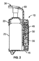
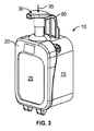
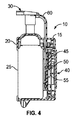
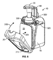
図1から図4は、本体15及びディスペンサーカバー20を有するポイントオブケア(point-of-care)ディスペンサー10を示す。本体15及びディスペンサーカバー20は、手衛生カートリッジ25又は手衛生製品のための他の容器を収容するように寸法化されている。手衛生製品は、ケアディスペンサーの上部において分注ポンプ30を矢印35により示される方向に駆動することによって手衛生カートリッジ25から分注される。
FIGS. 1-4 show a point-of-
分注ポンプ30が駆動されたことを示す超低パワーのRF信号を提供するために様々な低パワー送信要素が本体15の後部に配置されている。この例示において、全般的に40で示される超低パワー送信要素は、本体15の後部に配置される。この例示において、超低パワー送信要素40は、超低パワー無線ユニット45と、トリガー磁石50と、リードスイッチ55と、を有する。
Various low power transmission elements are located at the rear of the
操作時、分注ポンプ30が押されると、その移動は、追従部60によって追跡される。トリガー磁石50は、分注ポンプ30が押されて解放されたときに追従部60と共に移動するように構成されている。同様に、トリガー磁石50の動作は、超低パワー無線ユニット45を起動するリードスイッチ55を駆動させる。リードスイッチ55によってトリガー磁石50の磁場が作用するため、超低パワー無線ユニット45が励磁され、超低パワーRF信号送信によってディスペンサー使用事象を送信する。2.5秒といった所定時間内に生じる複数回の押し込みは、複数の作動による単一の使用事象を示すように校合されてもよい。
In operation, when the dispensing
トリガー磁石50は、手衛生製品の適した量を分注するためにポンプが十分に作動される手衛生事象のみを報告するように配置される。ストロークの上部へとポンプが戻るとき、追従部60も戻しばねによって推進され、トリガー磁石50の磁石がリードスイッチ55に作用する磁場を生成しないことを確実とする。
The
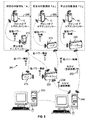
ポイントオブケアディスペンサー10の相対位置は、所定の対象領域内でポイントオブケアディスペンサー10が作動されるときに追跡されてもよい。図5は、こうした追跡を実行し得る電子的手衛生事象監視システム200を示す。
The relative position of the point of
この例示において、ポイントオブケアディスペンサー10は、矢印205によって示されるように、所定の対象区域A、B及びCの間で携帯可能である。ポイントオブケアディスペンサー10の駆動は、ポイントオブケアディスペンサー10と、各所定の対象区域A、B又はC内にそれぞれ配置された対応するより高いパワーの送受信機と、の間の最大距離に全般的に制限された範囲を有する、第1のパワーレベルのRF送信事象をもたらす。範囲は、複数の所定の対象区域のうちの第1の区域におけるポイントオブケアディスペンサー10からのRF送信事象が、複数の所定の対象区域のうちの第2の区域における送受信機によって受信されないように、選択されてもよい。しかしながら、いくつかの例では、第1の対象区域からのRF送信事象は、偶発的に第2の所定の対象区域へと伝わる。しかしながら、RF送信事象は異なる振幅を有し、対応する送受信機は、たとえば所定の信号振幅を超えて生じるRF送信事象のみを受け入れ/応答することによって、信号振幅を用いて、異なる所定の対象区域において生じるRF送信事象間を特定し得る。それぞれの所定の対象区域における送受信機は、異なる区域の大きさに適合するように、異なる所定の信号振幅に対して応答するように構成されてもよい。追加的に、携帯可能なポイントオブケアディスペンサー10は、ディスペンサー使用事象と共に、携帯可能なディスペンサーである事象のソースを特定する身元確認を送信するように構成されてもよい。この追加により、ディスペンサー使用事象は、事象の受信の際に、特定されてもよい。
In this illustration, the point-of-
1つの例示において、第1のパワーレベルは、約1メートルから3メートルまでの間の送信範囲を有する超低パワー信号であってもよい。超低パワー信号のレベルは、超低パワー無線ユニット45に対するトリガー磁石50及びリードスイッチ55の相対運動によって生成されるパワーに対応してもよい。手衛生事象監視システム200において複数のポイントオブケアディスペンサーが使用されてもよく、この場合において、各ポイントオブケアディスペンサーが、他から各特定のポイントオブケアディスペンサーを区別する固有のデジタルコードを送信してもよい。
In one example, the first power level may be an ultra low power signal having a transmission range between about 1 meter and 3 meters. The level of the ultra low power signal may correspond to the power generated by the relative movement of the
複数の所定の対象区域の間でポイントオブケアディスペンサー10が移動される様々な状況が存在する。たとえば、ポイントオブケアディスペンサー10は、患者のベッド、IVユニット、患者監視システム等に対して取り付けるために構成されてもよく、ポイントオブケアディスペンサー10が取り付けられる特定の対象物は、複数の所定の対象区域の間で移動できる。
There are various situations in which the point of
手衛生事象監視システム200は、所定の対象区域におけるディスペンサーの使用を監視する。医療施設において、例えば、対象区域は、識別された患者を看護する位置に対応してもよい。監視システム200は、所定の対象区域内に及び所定の対象区域に関連付けられてそれぞれ配置された複数のRF送受信機を有する。RF送受信機によって受信されるディスペンサー使用事象は、RF送受信機が配置された対象区域に関連付けられている。
Hand hygiene
RF送受信機のそれぞれは、それぞれの所定の対象区域内のポイントオブケアディスペンサーからRF送信事象を受信し、当該所定の対象区域を超えて拡がる範囲を有する第2のパワーレベルで、更なるRF信号を送信するように構成されている。1つの例示において、第2のパワーレベルは、約30メートルから60メートルまでの間の送信範囲を有してもよい。 Each of the RF transceivers receives an RF transmission event from a point-of-care dispenser within a respective predetermined area of interest and further RF signals at a second power level having a range extending beyond the predetermined area of interest. Is configured to send. In one illustration, the second power level may have a transmission range between about 30 meters and 60 meters.
複数のRF送受信機の1つ以上は、壁、デスク、ドア等のようなそれぞれの所定の対象区域内の固定された位置に配置されてもよい。複数のRF送受信機の少なくとも1つは、1)所定の対象区域Aに示されたような固定されたポイントオブケアディスペンサー210、2)所定の対象区域Bに示されたような固定されたハブ215、及び/又は、3)所定の対象区域Cに示されたようなゲートウェイ220であってもよい。1つの例示において、超低パワー無線ユニット45は送受信機であってもよく、この場合において、監視システムネットワークを構成する固定された位置のポイントオブケアディスペンサー、ハブ及びゲートウェイは、ポイントオブケアディスペンサー10が送信する短距離メッセージを受信し認識する機能を有してもよい。第2のパワーレベルで送信する固定されたポイントオブケアディスペンサーからの事象ではなく、携帯可能なディスペンサーから受信された事象を識別することが、これらの事象を送信するために、固定されたポイントオブケアディスペンサーにとって好適となるかもしれず、別の固定されたポイントオブケアディスペンサーによる再送を必要とすることはない。
One or more of the plurality of RF transceivers may be located at a fixed location within each predetermined area of interest, such as a wall, desk, door, or the like. At least one of the plurality of RF transceivers is: 1) a fixed point-of-care dispenser 210 as shown in the predetermined target area A, 2) a fixed hub as shown in the predetermined
ポイントオブケアディスペンサーによって送信され、固定された位置の装置(ディスペンサー/ハブ/ゲートウェイ)によって収集されたディスペンサー使用事象データは、固定された位置の送受信機と関連付けられた所定の対象領域に割り当てられ得る。これは、残りのシステムを通してポイントオブケアディスペンサー使用事象データを送信する前に、固定された位置の装置の特定の身元確認をポイントオブケアディスペンサー使用事象データに付加することによって、実現されてもよい。言い換えれば、ポイントオブケアディスペンサー10がその送信における固有の識別子を有する場合において、固定された位置の送受信機の固有の識別子は、残りのシステムに対してポイントオブケアディスペンサーの固有の識別子を送信する前に、ポイントオブケアディスペンサーの固有の識別子に付加される。
Dispenser usage event data transmitted by a point-of-care dispenser and collected by a fixed location device (dispenser / hub / gateway) may be assigned to a predetermined area of interest associated with a fixed location transceiver. . This may be accomplished by adding a specific identification of the fixed location device to the point-of-care dispenser usage event data before sending the point-of-care dispenser usage event data through the rest of the system. . In other words, if the point-of-
手洗い事象データは、各所定の対象区域内のより高いパワーの送受信機から、1)GSM(登録商標)230、2)ゲートウェイ220、及び/又は、3)ハブ215の1つ以上へと送信され、1つ以上のコンピュータ245へと送信される。コンピュータ245は、コンピュータ250に対して事象データを通信してもよく、事象データは、医療施設による使用に適したフォーマットへとコンパイルされる。
Hand wash event data is sent from one or more of the higher power transceivers in each predetermined area of interest to 1)
一度ポイントオブケアディスペンサー使用データが監視システムネットワークに入ると、固定されたディスペンサーの使用データと同様にネットワークによって処理され、データ収集サーバまで送られる。壁に取り付けられたディスペンサー及びポイントオブケアディスペンサーの両方からのディスペンサー使用データは、次いで、関連する所定の対象領域に割り当てられることができ、その領域のための手衛生順守計算において使用され得る。 Once the point-of-care dispenser usage data enters the surveillance system network, it is processed by the network and sent to the data collection server in the same way as the fixed dispenser usage data. Dispenser usage data from both wall-mounted dispensers and point-of-care dispensers can then be assigned to an associated predetermined target area and used in hand hygiene compliance calculations for that area.
図6から図12は、手衛生カートリッジ25の盗難といった問題に対処するセキュリティー機能を有するポイントオブケアディスペンサー10の様々な要素の例示である。図6は、開放位置にあるポイントオブケアディスペンサー10を、本体15のチャンバ内に装着された手衛生カートリッジ25と共に示す。図示された例において、手衛生カートリッジ25は、矢印305の方向に沿って本体15内へと挿入される。ディスペンサーカバー20は、次いで、ヒンジ連結部315周りに矢印310により示された方向に閉塞位置へと回転され得る。
FIGS. 6-12 are illustrations of various elements of the point-of-
閉塞位置において、ディスペンサーカバー20及び本体15の複数の要素は、ディスペンサーカバー20の上部と本体15の上部とを互いに拘束するように互いに係合する。図示された例において、ディスペンサーカバー20のディスペンサーカバー拘束要素は、ポイントオブケアディスペンサー10が閉塞されたときに、本体15の対応する本体拘束要素と滑らかに係合する。しかしながら、一度ディスペンサーカバー20及び本体15の拘束要素が係合されると、ポイントオブケアディスペンサー10を拘束解除するための鍵325が用いられない限り、権限のないアクセスが防止される。権限のない個人によるディスペンサーカバー20を本体15からこじ開けようとする試みは、拘束要素をより堅くより大きな力で互いに係合させ、これにより手衛生カートリッジ25の盗難を阻止する。
In the closed position, the
本体15の拘束機構は、本体15の上部においてチャンバの両側に配置された、手衛生カートリッジ25を保持するために用いられる拘束アーム350を有する。それぞれの拘束アーム350は、クロスバー360と係合する後部355を有し、クロスバー360は、拘束アーム350を互いに連結するために後部355の間で延びる。各拘束アーム350の後部355は、本体15の内側表面から延びるタブ375に対する付勢力370を提供する拘束ばね365で終端する。1つの例示において、拘束ばね365は、弾性材料から形成され、本体15の後部の長さに沿って延びる。このように構成されたとき、拘束ばね365は、タブ375と係合する上部380で終端する対向する端部を有してもよい。湾曲部385は、各上部380からそれぞれ延び、拘束ばね365の下側横断部材390の中間部で終端する。湾曲部385は、後部355が上方向にタブ375に対して動かされたときに変形する。この変形は、上方移動に対抗する下方向への付勢力370をもたらす。
The restraining mechanism of the
各拘束アーム350は、概ね円形断面を有する枢動部400を更に有する。鍵筒405は、各拘束アーム350の枢動部400から本体15の外部へ向かって延び、ここで鍵325を受容してもよい。レール410は、枢動部400の下方に配置され、一方の側でタブ415と係合し、他方の側で枢動ばね420と係合する。1つの例示において、枢動ばね420は、鍵筒405の下部と固定係合する第1の端部430と、レール410近傍の第2の広がった端部435と、を含む、可撓性アーム425を有する。枢動部400がその軸線周りに回転されるとき、広がった端部435は、レール410と係合して可撓性アーム425を変形させ、これにより拘束アーム350の回転に抗する付勢力を提供する。拘束ばね365及び枢動ばね420の組み合わされた付勢力は、拘束アーム350をそれらの通常位置へと方向付け、拘束アーム350の下側後部は、それぞれのレール410上に載る。
Each restraining
各拘束アーム350の前側部は、本体連結部440の主要部において終端する。図示された例の各本体連結部440は、枢動部400から延びるアーム445と、鉛直方向に沿ってアーム445を少なくとも部分的に貫通して延びる開口部450と、係止要素460と、を有する。係止要素460の後部は、平面と、本体連結部のアンダーカットを形成するへりと、を有する。係止要素460の前部は、概ね曲面化された下側面と、後方に傾斜した上側面と、を有する。
The front side portion of each restraining
ディスペンサーカバー連結部465は、それぞれの本体連結部440と係合するようにディスペンサーカバー20の内部表面から延びる。それぞれのディスペンサーカバー連結部465は、ディスペンサーカバー20の後部へ向かって延び、係止要素460を受容するように構成された矩形開口部470において終端する、一対の平行な側壁を有してもよい。側壁は、ディスペンサーカバー連結部のアンダーカットを形成するように、矩形開口部470の下側縁においてクロスバー473によって連結されてもよい。ディスペンサーカバー連結部のアンダーカットは、拘束アーム350の開口部450と係合するように構成される。更に、それぞれの側壁は、ディスペンサーカバー20が本体15を閉塞するときに、係止要素460の前部と係合するように構成されたそれぞれのカム475において終端してもよい。
The dispenser
図7は、本体15を閉塞するようにディスペンサーカバー20が矢印310の方向に回転されたときの本体連結部440及びディスペンサーカバー連結部465を示す。この動作の間、係止要素460の後方に傾斜した上側面は、それぞれのカム475の対応する湾曲表面と係合し、これにより拘束ばね365及び枢動ばね420の力に対抗して枢動部400周りにレバーアームを回転させる。カム動作は、ディスペンサーカバー20の閉塞位置への滑らかな移動を提供し、ディスペンサーカバー20は本体15と拘束される。このように、本体連結部440及びディスペンサーカバー連結部465の両方の導入面は、閉塞位置への互いの通過を容易にする。
FIG. 7 shows the main
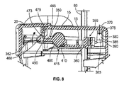
図8及び図9は、閉塞位置にある本体15及びディスペンサーカバー20を示す。一度ディスペンサーカバー20が部分的閉塞位置から図8及び図9に示される完全閉塞位置へと回転されると、係止要素460の後方に傾斜した上側表面は、もはやそれぞれのカム475の湾曲表面と係合されない。その代わり、拘束アーム350は、ディスペンサーカバー連結部465との係合、特にディスペンサーカバー連結部のアンダーカットとの係合へと係止要素460を駆動するように、拘束ばね365及び枢動ばね420の力に応じて矢印352により示されるようにそれらの枢動部400周りに回転する。この位置において、各係止要素460のへりは、対応するディスペンサーカバー連結部465の矩形開口部470内へと延びる。同様に、閉塞位置において、各矩形開口部470の下側縁におけるクロスバーは、それぞれのアーム445において開口部450と係合する。本体15に対してディスペンサーカバー20が完全に閉塞されると、拘束ばね365によって提供される力は、本体連結部440及びディスペンサーカバー連結部465の主要な機構が互いに完全に係合されることを確実にする。
8 and 9 show the
ポイントオブケアディスペンサー10のディスペンサーカバー20が、これを開放しようとする要求されていない企てにおいててこの力を受ける場合、付与される荷重が増加するにつれて、拘束の完全性が実質的に増加する。より詳細には、本体連結部440のアンダーカット機構及びディスペンサーカバー連結部465のアンダーカット機構は、これらが引き離されるにつれ、互いにより堅く係合する。
If the
拘束の安全性の更なる向上のため、外部から付与された力がポイントオブケアディスペンサー10内から拘束を取り除くのを阻止する付加的な機構が、鍵筒405内に構築されている。より詳細には、鍵筒405は、組み立ての間、鍵筒405がディスペンサー本体の拘束保持機構を乗り上げ且つ乗り越すように弾性的に変形可能である。一度拘束がかかると、ポイントオブケアディスペンサー内へとアクセスしようとする企てにおいて力が付与されたときに、拘束保持機構によって、拘束が保持され更なる内方又は外方への移動のいずれもが制限される。
In order to further improve the safety of the restraint, an additional mechanism is constructed in the
盗難に対して拘束されたままにするためのポイントオブケアディスペンサー10の機能と同じくらい重要なものは、開放することを許可された者によって容易に開放され、これらの者が使用済みの手衛生製品のパックを交換するためにアクセスすることを可能にする、ポイントオブケアディスペンサー10の機能である。ポイントオブケアディスペンサー10を開放しやすくする一例が、図11及び図12に示される。ここで、鍵筒405を介して枢動部400を拘束ばね365により提供される付勢力に抗して矢印327の方向に回転させるために鍵325が使用され、これにより、ディスペンサーカバー連結部465から本体連結部440を係合解除させ、ポイントオブケアディスペンサー10が矢印477で示される方向に開放されるのを可能とする。ポイントオブケアディスペンサー10の開放の過程の間、本体15の前縁と一体の複数のカバー開放ばね480は、矢印483の方向に力を働かせ、ディスペンサーカバー20を開放させるように駆動するのを支援する。この過程の間にカバーを略自動的な方法で開放することを確実とすることにより、操作者は拘束解除過程が成し遂げられたという視覚的指示を受けるため、鍵325の過度の回転により引き起こされる拘束部の損傷を回避することができる。
As important as the function of the point-of-
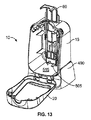
ポイントオブケアディスペンサー10内に手衛生カートリッジ25を固定することに加え、適切な位置からのポイントオブケアディスペンサー10全体の要求されていない除去を制限するために、同様に安全な取り付けのオプションが望まれ得る。これに関し、図13から図17は、水平ドッキングユニット490に取り付けられたポイントオブケアディスペンサー10を示す。この水平ドッキングユニット490は、例えばヘルスケア機器の部品の上部水平表面上に、しっかりと機械的に締結されてもよい。機械的締結は、例えばオーバーベッドテーブル又はナイトスタンドに水平ドッキングユニット490をねじで固定又は接着的に固定することを含み得る。
In addition to securing the
ポイントオブケアディスペンサー10を水平ドッキングユニット490に固定するのに用いられる要素は、ディスペンサーカバー20を本体15から係合解除させてディスペンサー10が開放されるときにのみディスペンサー10の除去を可能とするように構成されてもよい。この目的を達成するため、ポイントオブケアディスペンサー10を水平ドッキングユニット490に固定するのに用いられる要素は、ディスペンサーが開放されたときにのみ操作可能である。
The elements used to secure the point-of-
図13〜図17に示された例では、水平ドッキングユニット490は、ポイントオブケアディスペンサー10の底前部及び底後部において対応する取り付け受容部500と係合するように構成された複数の取り付けタブ495を有する。取り付けタブ495を取り付け受容部500と係合させることにより、水平ドッキングユニット490の固定タブ505は、ポイントオブケアディスペンサー10の床部515を貫通する開口部510を通って延びる。固定タブ505は、水平ドッキングユニット490からディスペンサー10を取り外すために付与されるより大きな力が、固定タブ505と開口縁部との間の固定力において、対応する増加を生じさせるように、開口部510の1つ以上の縁部と係合するアンダーカットを有する。しかしながら、一度ディスペンサー10が開放されると、固定タブ505は、ディスペンサー10を水平ドッキングユニット490から解放するように、開口部510の外側に弾性的に方向付けられてもよい。
In the example shown in FIGS. 13-17, the
図18及び図19は、様々な個別の締め付けオプションを示し、機械的固定部及び/又は不正防止の機械的固定部の使用を通して、ポイントオブケアディスペンサー10を様々なヘルスケア機器にしっかりと取り付けることができる。このような機器は、矩形及び環状レール(水平)と、支持部(鉛直)と、をしばしば有する。より詳細には、図18は、ポイントオブケアディスペンサー10の後部に固定されたブラケット520を示し、ブラケット520は、水平な支持部に対してディスペンサー10を固定するように構成されている。図19は、ポイントオブケアディスペンサー10の後部に対して固定された更なるブラケット525を示し、ブラケット525は、鉛直な支持部に対してディスペンサー10を固定するように構成されている。
FIGS. 18 and 19 show various individual tightening options and secure the point-of-
図20は、ポイントオブケアディスペンサー10の後部に対して固定されたブラケット530を示し、ブラケット530は、オーバーベッドテーブルの鉛直な脚部にポイントオブケアディスペンサー10を取り付けるように特別に設計されている。図21は、ブラケット530を用いて鉛直な脚部535に対して取り付けられたポイントオブケアディスペンサー10を示す。繰り返すと、取り付けブラケット530の除去を成功させるためには機械的な道具が必要とされるため、機械的な取り付けの使用により、機会を伺う泥棒に対するディスペンサー10の安全性を維持することができる。
FIG. 20 shows a
Claims (20)
複数の所定の対象区域の間で移動可能なポイントオブケアディスペンサーであって、当該ポイントオブケアディスペンサーの駆動が、当該ポイントオブケアディスペンサーが駆動された1つの前記所定の対象区域に全般的に制限された送信範囲を有する第1のパワーレベルでRF送信事象を生じさせる、ポイントオブケアディスペンサーと、
それぞれの前記所定の対象区域内に配置された複数のRF送受信機と、を具備し、
それぞれの前記RF送受信機が、それぞれの前記所定の対象区域におけるポイントオブケアディスペンサーから前記RF送信事象を受信し、当該所定の対象区域を超えて拡がる送信範囲を有する第2のパワーレベルで更なるRF信号を送信するように構成された、電子的手衛生事象監視システム。 An electronic hand hygiene event monitoring system,
A point-of-care dispenser that is movable between a plurality of predetermined target areas, wherein the driving of the point-of-care dispenser is generally limited to the one predetermined target area in which the point-of-care dispenser is driven A point-of-care dispenser for generating an RF transmission event at a first power level having a specified transmission range;
A plurality of RF transceivers arranged in each of the predetermined target areas,
Each said RF transceiver receives said RF transmission event from a point-of-care dispenser in each said predetermined target area and further at a second power level having a transmission range extending beyond said predetermined target area An electronic hand hygiene event monitoring system configured to transmit an RF signal.
手衛生カートリッジチャンバを画定する内部を有する本体と、
ディスペンサーカバーであって、前記本体に対する開放状態と前記本体に対する閉塞状態との間の当該ディスペンサーカバーの枢動運動のために、前記本体と結合された、ディスペンサーカバーと、
アンダーカット機構を有する、前記本体に対して固定された少なくとも1つの本体連結部と、
前記ディスペンサーカバーに対して固定された少なくとも1つのディスペンサーカバー連結部と、を具備し、
前記少なくとも1つのディスペンサーカバーが、アンダーカット機構を有し、前記少なくとも1つのディスペンサーカバー連結部の前記アンダーカット機構と、前記少なくとも1つの本体連結部の前記アンダーカット機構とが、前記ディスペンサーカバーが前記本体に対して閉塞位置にあるときに互いに係合し、前記アンダーカット機構の間の係合は、前記ディスペンサーカバーを前記閉塞状態から前記開放状態へと動かすために使用されるてこの力の増加に応じて強まる、ポイントオブケアディスペンサー。 A point of care dispenser,
A body having an interior defining a hand hygiene cartridge chamber;
A dispenser cover coupled to the body for pivotal movement of the dispenser cover between an open state relative to the body and a closed state relative to the body;
At least one body connecting portion fixed to the body having an undercut mechanism;
And at least one dispenser cover connecting portion fixed to the dispenser cover,
The at least one dispenser cover has an undercut mechanism, and the undercut mechanism of the at least one dispenser cover connecting portion and the undercut mechanism of the at least one main body connecting portion include the dispenser cover, Engaging with each other when in the closed position relative to the body, the engagement between the undercut mechanisms increases the leverage used to move the dispenser cover from the closed state to the open state. A point-of-care dispenser that strengthens according to your needs.
拘束ばねと、
拘束アームであって、
前記拘束ばねと係合するように構成された後部と
前記拘束アームの枢動軸周りの回転を可能とするように構成された枢動部と
前記アームの前部近傍に形成された係止要素と
前記係止要素近傍で前記拘束アームを少なくとも部分的に貫通して延びる鉛直開口部と
を有する拘束アームと、を具備する、請求項11に記載のポイントオブケアディスペンサー。 The at least one body connecting portion is
A restraining spring;
A restraining arm,
A rear portion configured to engage with the restraining spring; a pivot portion configured to allow rotation of the restraining arm about a pivot axis; and a locking element formed in the vicinity of the front portion of the arm. A point-of-care dispenser according to claim 11, comprising: a restraining arm having: and a vertical opening extending at least partially through the restraining arm in the vicinity of the locking element.
前記ディスペンサーカバーの後部に向かって延び、前記係止要素を受容するように構成された矩形開口部において終端する、一対の平行な側壁と、
前記拘束アームの前記鉛直開口部と係合するように構成された前記ディスペンサーカバー連結部のアンダーカットを形成するために、前記矩形開口部の下側縁近傍に配置されたクロスバーと、を具備する、請求項12に記載のポイントオブケアディスペンサー。 The dispenser cover connecting portion is
A pair of parallel side walls extending toward the rear of the dispenser cover and terminating in a rectangular opening configured to receive the locking element;
A crossbar disposed near the lower edge of the rectangular opening to form an undercut of the dispenser cover coupling portion configured to engage the vertical opening of the restraining arm. The point-of-care dispenser according to claim 12.
ディスペンサーカバー及び本体を有するポイントオブケアディスペンサーと、
閉塞状態において前記ディスペンサーカバーを前記本体と固定するように構成された拘束機構であって、前記閉塞状態において前記ディスペンサーカバーが前記本体と固定されたときに、前記ポイントオブケアディスペンサーの内部に主に配置される、拘束機構と、
前記ポイントオブケアディスペンサーと共に取り付けるように構成されたドッキングユニットと、を具備し、
前記ドッキングユニット及び前記ポイントオブケアディスペンサーが、前記ディスペンサーカバー及び前記本体が開放状態にあるときにのみ前記ポイントオブケアディスペンサーを前記ドッキングユニットから解放するためにアクセス可能な更なる拘束機構により、相互連結されている、ポイントオブケア分注システム。 A point-of-care dispensing system,
A point-of-care dispenser having a dispenser cover and body;
A restraining mechanism configured to fix the dispenser cover to the main body in the closed state, and is mainly inside the point-of-care dispenser when the dispenser cover is fixed to the main body in the closed state. A restraining mechanism disposed;
A docking unit configured to be attached with the point-of-care dispenser,
The docking unit and the point-of-care dispenser are interconnected by a further restraining mechanism that is accessible to release the point-of-care dispenser from the docking unit only when the dispenser cover and the body are open. A point-of-care dispensing system.
Applications Claiming Priority (3)
| Application Number | Priority Date | Filing Date | Title |
|---|---|---|---|
| US14/185,568 US20150235549A1 (en) | 2014-02-20 | 2014-02-20 | Electronically monitored and portable point-of-care hand hygiene dispenser having security features |
| US14/185,568 | 2014-02-20 | ||
| PCT/US2015/011328 WO2015126538A1 (en) | 2014-02-20 | 2015-01-14 | Electronically monitored and portable point-of-care hand hygiene dispenser having security features |
Related Child Applications (1)
| Application Number | Title | Priority Date | Filing Date |
|---|---|---|---|
| JP2019093185A Division JP6788070B2 (en) | 2014-02-20 | 2019-05-16 | Electronically monitored and portable point of care hand hygiene dispenser with security features |
Publications (1)
| Publication Number | Publication Date |
|---|---|
| JP2017512514A true JP2017512514A (en) | 2017-05-25 |
Family
ID=53798606
Family Applications (2)
| Application Number | Title | Priority Date | Filing Date |
|---|---|---|---|
| JP2016553314A Pending JP2017512514A (en) | 2014-02-20 | 2015-01-14 | Electronically monitored and portable point-of-care hand hygiene dispenser with security function |
| JP2019093185A Active JP6788070B2 (en) | 2014-02-20 | 2019-05-16 | Electronically monitored and portable point of care hand hygiene dispenser with security features |
Family Applications After (1)
| Application Number | Title | Priority Date | Filing Date |
|---|---|---|---|
| JP2019093185A Active JP6788070B2 (en) | 2014-02-20 | 2019-05-16 | Electronically monitored and portable point of care hand hygiene dispenser with security features |
Country Status (13)
| Country | Link |
|---|---|
| US (3) | US20150235549A1 (en) |
| EP (1) | EP3108463B1 (en) |
| JP (2) | JP2017512514A (en) |
| CN (1) | CN106233351B (en) |
| AU (1) | AU2015219485B2 (en) |
| BR (1) | BR112016019207B1 (en) |
| CA (1) | CA2939449C (en) |
| MX (1) | MX366203B (en) |
| NZ (1) | NZ723185A (en) |
| PL (1) | PL3108463T3 (en) |
| RU (1) | RU2671716C2 (en) |
| SG (2) | SG10201707529XA (en) |
| WO (1) | WO2015126538A1 (en) |
Families Citing this family (24)
| Publication number | Priority date | Publication date | Assignee | Title |
|---|---|---|---|---|
| USRE48951E1 (en) | 2015-08-05 | 2022-03-01 | Ecolab Usa Inc. | Hand hygiene compliance monitoring |
| CA3085086C (en) | 2011-12-06 | 2023-08-08 | Delta Faucet Company | Ozone distribution in a faucet |
| CN107073507B (en) * | 2014-10-27 | 2019-07-05 | 格瑞克明尼苏达有限公司 | Quick release solenoid component |
| US10022023B2 (en) * | 2015-04-07 | 2018-07-17 | Vi-Jon, Inc. | Dispenser assembly |
| US9940819B2 (en) | 2015-05-06 | 2018-04-10 | The Uab Research Foundation | Systems and methods for encouraging hand washing compliance |
| US10149575B2 (en) | 2015-10-08 | 2018-12-11 | Gojo Industries, Inc. | Slide open refillable dispenser |
| CA3007437C (en) | 2015-12-21 | 2021-09-28 | Delta Faucet Company | Fluid delivery system including a disinfectant device |
| US10044710B2 (en) | 2016-02-22 | 2018-08-07 | Bpip Limited Liability Company | Device and method for validating a user using an intelligent voice print |
| US11000160B1 (en) * | 2016-05-20 | 2021-05-11 | Romell K. Jackson | Below table sanitary system and method of use |
| GB2559103A (en) * | 2016-10-14 | 2018-08-01 | Bradley Mark | Dispensing system |
| US11272815B2 (en) * | 2017-03-07 | 2022-03-15 | Ecolab Usa Inc. | Monitoring modules for hand hygiene dispensers |
| AU2017439486B2 (en) * | 2017-11-17 | 2021-05-20 | Essity Hygiene And Health Aktiebolag | A hygiene monitoring system |
| CN111684500B (en) * | 2018-02-08 | 2022-03-04 | 易希提卫生与保健公司 | Sanitary fixture mounting |
| DE202018106397U1 (en) | 2018-11-12 | 2019-01-29 | Icon Guest Concepts & Supply Gmbh | Device for dispensing a liquid product |
| CN109528045A (en) * | 2018-11-20 | 2019-03-29 | 慈溪市舒润卫浴实业有限公司 | A kind of Novel bathroom liquid storage device |
| IT201800010692A1 (en) * | 2018-11-29 | 2020-05-29 | Gfl S A | DISPENSING GROUP |
| US11284333B2 (en) | 2018-12-20 | 2022-03-22 | Ecolab Usa Inc. | Adaptive route, bi-directional network communication |
| WO2021021611A1 (en) * | 2019-07-26 | 2021-02-04 | Gojo Industries, Inc. | Systems and methods for increased accuracy for tracking hygiene compliance |
| WO2021190741A1 (en) * | 2020-03-25 | 2021-09-30 | Essity Hygiene And Health Aktiebolag | Bracket |
| US11332279B2 (en) * | 2020-09-25 | 2022-05-17 | World Club Supply Corporation | Liquid dispenser apparatus |
| USD1010444S1 (en) | 2021-08-13 | 2024-01-09 | World Club Supply Corp. | Combined pump top and skirt |
| USD994498S1 (en) | 2021-08-13 | 2023-08-08 | World Club Supply Corporation | Liquid dispenser |
| USD996975S1 (en) | 2021-08-13 | 2023-08-29 | World Club Supply Corporation | Liquid dispenser apparatus |
| US11744413B2 (en) | 2021-10-07 | 2023-09-05 | Deb Ip Limited | Dispenser assembly |
Citations (2)
| Publication number | Priority date | Publication date | Assignee | Title |
|---|---|---|---|---|
| US20090195385A1 (en) * | 2008-02-04 | 2009-08-06 | Ching Ching Huang | Proactive hand hygiene monitoring system |
| US20130122807A1 (en) * | 2011-11-08 | 2013-05-16 | Versus Technology, Inc. | Systems and methods for effecting good hygiene practices |
Family Cites Families (27)
| Publication number | Priority date | Publication date | Assignee | Title |
|---|---|---|---|---|
| US5226625A (en) * | 1991-08-05 | 1993-07-13 | Bobrick Washroom Equipment, Inc. | Container mounting system |
| US6269837B1 (en) * | 1998-11-09 | 2001-08-07 | The Procter & Gamble Company | Rechargeable dispensing system |
| US6131773A (en) * | 1998-12-30 | 2000-10-17 | Steris Inc | Mounting and locking mechanism for a soap dispenser |
| US7174678B2 (en) | 1999-04-22 | 2007-02-13 | Hill-Rom Services, Inc. | Modular patient room |
| US6619509B2 (en) * | 2000-04-10 | 2003-09-16 | The Dial Corporation | Liquid dispenser |
| US6392546B1 (en) * | 2000-09-07 | 2002-05-21 | Judson L. Smith | Hand washing compliance measurement and recording system |
| US7051987B2 (en) * | 2003-07-31 | 2006-05-30 | Yi-Chen Chen | Liquid soap dispenser |
| CA2496412C (en) * | 2005-02-09 | 2013-06-18 | Hygiene-Technik Inc. | Fluid dispenser lock defeater |
| US7845520B2 (en) * | 2005-03-15 | 2010-12-07 | Kimberly-Clark Worldwide, Inc. | Mounting plate and kit to provide water resistance for a dispenser |
| US20070028999A1 (en) * | 2005-06-22 | 2007-02-08 | Roger Bissonnette | Inflatable Elastomeric Plug For A Dual Containment Piping System |
| DK2317700T3 (en) * | 2006-02-10 | 2016-08-22 | Hyintel Ltd | A system and method for monitoring hygiene standards compliance |
| US7854354B2 (en) * | 2006-06-12 | 2010-12-21 | Rodney Laible | Docking station for a liquid container including a liquid dispenser |
| US20070289987A1 (en) * | 2006-06-16 | 2007-12-20 | Paul Francis Tramontina | Modular Hand Care System |
| WO2008088424A1 (en) * | 2006-11-01 | 2008-07-24 | Infection Prevention Systems, Inc. | Hand hygiene verification/tracking system and method |
| WO2008119158A1 (en) * | 2007-03-30 | 2008-10-09 | Toronto Rehabilitation Institute | Hand hygiene compliance system |
| US8237558B2 (en) * | 2007-03-30 | 2012-08-07 | University Health Network | Hand hygiene compliance system |
| US8350706B2 (en) * | 2009-06-30 | 2013-01-08 | Gojo Industries, Inc. | Hygiene compliance monitoring system |
| US8561847B2 (en) * | 2009-07-20 | 2013-10-22 | Gojo Industries, Inc. | Dispenser housing with locking mechanism |
| US8479956B2 (en) * | 2009-11-03 | 2013-07-09 | The Dial Corporation | Soap dispenser having a keyed bottle system |
| US20110121974A1 (en) * | 2009-11-20 | 2011-05-26 | Versus Technology, Inc. | Real-time method and system for monitoring hygiene compliance within a tracking environment |
| US8564431B2 (en) * | 2010-01-07 | 2013-10-22 | Ultraclenz, Llc | Wireless monitoring and communication for sanitizer dispenser systems |
| US20120248140A1 (en) * | 2010-01-22 | 2012-10-04 | Mert Iseri | Portable hand sanitation dispenser |
| DE202010009176U1 (en) * | 2010-06-17 | 2011-12-19 | Ada Cosmetic Gmbh | Wanddosierspender |
| US8744623B2 (en) * | 2011-05-26 | 2014-06-03 | Ecolab Usa Inc. | Timed dispenser and audit system |
| US20130262034A1 (en) * | 2012-04-03 | 2013-10-03 | Mert Iseri | Hand hygiene tracking system |
| US9060655B2 (en) * | 2012-06-13 | 2015-06-23 | Swipesense, Inc. | Dispenser for hand sanitizer |
| US9340337B2 (en) * | 2012-05-01 | 2016-05-17 | Ecolab Usa Inc. | Dispenser with lockable pushbutton |
-
2014
- 2014-02-20 US US14/185,568 patent/US20150235549A1/en not_active Abandoned
-
2015
- 2015-01-14 NZ NZ723185A patent/NZ723185A/en unknown
- 2015-01-14 EP EP15752876.1A patent/EP3108463B1/en active Active
- 2015-01-14 CA CA2939449A patent/CA2939449C/en active Active
- 2015-01-14 BR BR112016019207-9A patent/BR112016019207B1/en active IP Right Grant
- 2015-01-14 WO PCT/US2015/011328 patent/WO2015126538A1/en active Application Filing
- 2015-01-14 PL PL15752876T patent/PL3108463T3/en unknown
- 2015-01-14 RU RU2016136315A patent/RU2671716C2/en active
- 2015-01-14 JP JP2016553314A patent/JP2017512514A/en active Pending
- 2015-01-14 AU AU2015219485A patent/AU2015219485B2/en active Active
- 2015-01-14 MX MX2016010633A patent/MX366203B/en active IP Right Grant
- 2015-01-14 SG SG10201707529XA patent/SG10201707529XA/en unknown
- 2015-01-14 SG SG11201606829UA patent/SG11201606829UA/en unknown
- 2015-01-14 CN CN201580009485.3A patent/CN106233351B/en active Active
- 2015-10-16 US US14/885,475 patent/US9920553B2/en active Active
-
2018
- 2018-03-13 US US15/919,772 patent/US20180202195A1/en not_active Abandoned
-
2019
- 2019-05-16 JP JP2019093185A patent/JP6788070B2/en active Active
Patent Citations (2)
| Publication number | Priority date | Publication date | Assignee | Title |
|---|---|---|---|---|
| US20090195385A1 (en) * | 2008-02-04 | 2009-08-06 | Ching Ching Huang | Proactive hand hygiene monitoring system |
| US20130122807A1 (en) * | 2011-11-08 | 2013-05-16 | Versus Technology, Inc. | Systems and methods for effecting good hygiene practices |
Also Published As
| Publication number | Publication date |
|---|---|
| BR112016019207B1 (en) | 2022-04-05 |
| US20150235549A1 (en) | 2015-08-20 |
| SG11201606829UA (en) | 2016-09-29 |
| RU2016136315A3 (en) | 2018-09-10 |
| PL3108463T3 (en) | 2019-03-29 |
| EP3108463A1 (en) | 2016-12-28 |
| WO2015126538A1 (en) | 2015-08-27 |
| US9920553B2 (en) | 2018-03-20 |
| NZ723185A (en) | 2020-05-29 |
| US20180202195A1 (en) | 2018-07-19 |
| BR112016019207A2 (en) | 2017-08-15 |
| CA2939449A1 (en) | 2015-08-27 |
| EP3108463A4 (en) | 2017-10-18 |
| SG10201707529XA (en) | 2017-10-30 |
| JP2019130415A (en) | 2019-08-08 |
| RU2671716C2 (en) | 2018-11-06 |
| AU2015219485A1 (en) | 2016-09-01 |
| US20160040455A1 (en) | 2016-02-11 |
| MX366203B (en) | 2019-07-02 |
| MX2016010633A (en) | 2016-11-23 |
| CN106233351A (en) | 2016-12-14 |
| AU2015219485B2 (en) | 2019-01-03 |
| EP3108463B1 (en) | 2018-10-10 |
| RU2016136315A (en) | 2018-03-23 |
| CA2939449C (en) | 2020-02-25 |
| JP6788070B2 (en) | 2020-11-18 |
| CN106233351B (en) | 2018-12-04 |
Similar Documents
| Publication | Publication Date | Title |
|---|---|---|
| JP6788070B2 (en) | Electronically monitored and portable point of care hand hygiene dispenser with security features | |
| AU2018201272B2 (en) | Sanitization protocol monitoring/compliance systems, apparatuses, methods, and software | |
| US10240361B2 (en) | Apparatus for dispensing sanitizer fluid and recording data pertaining to hand sanitization | |
| US10042984B2 (en) | System and method for monitoring hand hygiene | |
| US7551092B1 (en) | Sanitary monitoring system to monitor the hand sanitation of health care workers or other required sanitary activities | |
| US9030325B2 (en) | Hand washing enforcement system | |
| US20130229276A1 (en) | Systems and Methods for Providing Hand Washing and Sanitizing Alerts | |
| EP2956918B1 (en) | Hand hygiene dispenser monitor | |
| US20090324444A1 (en) | Door opening system | |
| US20130300572A1 (en) | System and method for hand cleansing | |
| GB2537179A (en) | Dispenser Apparatus | |
| US20220193287A1 (en) | Internet of things sanitization sprayer | |
| US20100321187A1 (en) | Dispensing and accountability system and method for assuring washing of hands | |
| US8922378B2 (en) | Dispensing and accountability system and method for assuring washing of hands | |
| Alić et al. | Ultra-low Power Beacon-based Hand Hygiene Assistance System for Hospitals and Care Facilities | |
| AU2015202919A1 (en) | A system and method of hygiene control |
Legal Events
| Date | Code | Title | Description |
|---|---|---|---|
| A621 | Written request for application examination |
Free format text: JAPANESE INTERMEDIATE CODE: A621 Effective date: 20171114 |
|
| A131 | Notification of reasons for refusal |
Free format text: JAPANESE INTERMEDIATE CODE: A131 Effective date: 20190205 |
|
| A601 | Written request for extension of time |
Free format text: JAPANESE INTERMEDIATE CODE: A601 Effective date: 20190424 |
|
| A02 | Decision of refusal |
Free format text: JAPANESE INTERMEDIATE CODE: A02 Effective date: 20191008 |