JP2017511532A - Method for configuring a software defined PCI Express (PCI-E) switch - Google Patents
Method for configuring a software defined PCI Express (PCI-E) switch Download PDFInfo
- Publication number
- JP2017511532A JP2017511532A JP2016555801A JP2016555801A JP2017511532A JP 2017511532 A JP2017511532 A JP 2017511532A JP 2016555801 A JP2016555801 A JP 2016555801A JP 2016555801 A JP2016555801 A JP 2016555801A JP 2017511532 A JP2017511532 A JP 2017511532A
- Authority
- JP
- Japan
- Prior art keywords
- packet
- switch
- node
- pci
- tlp
- Prior art date
- Legal status (The legal status is an assumption and is not a legal conclusion. Google has not performed a legal analysis and makes no representation as to the accuracy of the status listed.)
- Pending
Links
Images


Classifications
-
- G—PHYSICS
- G06—COMPUTING; CALCULATING OR COUNTING
- G06F—ELECTRIC DIGITAL DATA PROCESSING
- G06F13/00—Interconnection of, or transfer of information or other signals between, memories, input/output devices or central processing units
- G06F13/38—Information transfer, e.g. on bus
- G06F13/40—Bus structure
- G06F13/4004—Coupling between buses
- G06F13/4022—Coupling between buses using switching circuits, e.g. switching matrix, connection or expansion network
Landscapes
- Engineering & Computer Science (AREA)
- Physics & Mathematics (AREA)
- General Engineering & Computer Science (AREA)
- Theoretical Computer Science (AREA)
- Mathematical Physics (AREA)
- Computer Hardware Design (AREA)
- General Physics & Mathematics (AREA)
- Data Exchanges In Wide-Area Networks (AREA)
- Bus Control (AREA)
Abstract
本発明は、一般にネットワーキングおよびコンピュータアーキテクチャの技術分野に関し、より詳細には、ソフトウェア定義ネットワーク(SDN)ボックスと、少なくとも1つの上流ノードと、複数の下流ノードとを含むシステムを構成する手法に関するものである。ノードはいくつかのグループに分割され得る。各グループに、単一の上流ノードと、少なくとも1つの下流ノードとがある。上流ノードと下流ノードの間のすべてのパケットはSDNボックスによって転送される。SDNボックスは「PCI-Eスイッチ」として働き、上流ノードを各下流ノードと相互接続して、カプセル化されたパケット(内部はPCI-Eパケットである)を転送する。全体の通信プロセスを通じて、上流ノードは下流ノードを通常のローカルPCI-Eデバイスとして扱う。The present invention relates generally to the technical fields of networking and computer architecture, and more particularly to techniques for configuring a system that includes a software defined network (SDN) box, at least one upstream node, and a plurality of downstream nodes. is there. The nodes can be divided into several groups. Each group has a single upstream node and at least one downstream node. All packets between upstream and downstream nodes are forwarded by the SDN box. The SDN box acts as a “PCI-E switch”, interconnects the upstream node with each downstream node, and forwards the encapsulated packet (internally a PCI-E packet). Throughout the entire communication process, the upstream node treats the downstream node as a normal local PCI-E device.
Description
本発明は、一般にネットワーキングおよびコンピュータアーキテクチャの技術分野に関し、より詳細には、ソフトウェア定義ネットワーク(SDN)ボックス、上流ノードおよび下流ノードから成るシステムを構成する手法に関するものである。 The present invention relates generally to the technical fields of networking and computer architecture, and more particularly to techniques for constructing a system consisting of a software defined network (SDN) box, an upstream node, and a downstream node.
PCI-E(周辺装置相互接続エクスプレス)は、コンピュータシステムにおいて周辺デバイスを相互接続するのに用いられる第3世代の高性能I/Oバスである。PCI-Eは、PCIと称される前世代のI/Oバスと同一の用法モデルを採用する。PCI-Eは、メモリのリード/ライト、I/Oのリード/ライトおよびコンフィギュレーションのリード/ライトのトランザクションなどのよく知られているトランザクションをサポートする。既存のOSおよびデバイスドライバは、PCI-Eシステムにおいて変更なしで動作することができる(PCI-Eに関する詳細は、Ravi Budruk、Don Anderson、Tom Shanleyによる、Addison- Wesley Professional、2004年の「PCI Express system architecture」を参照されたい)。 PCI-E (Peripheral Device Interconnect Express) is a third generation high performance I / O bus used to interconnect peripheral devices in a computer system. PCI-E uses the same usage model as the previous generation I / O bus called PCI. PCI-E supports well-known transactions such as memory read / write, I / O read / write, and configuration read / write transactions. Existing OS and device drivers can work without modification on PCI-E systems (for more information on PCI-E, see Ravi Budruk, Don Anderson, Tom Shanley, Addison-Wesley Professional, 2004 PCI Express see system architecture).
サーバの中にそれほどスペースがないので、PCI-Eスロットの数は通常制限されている。上記の問題に取り組むためにExpEther(Express Ethernet、http://www.expether.org/を参照されたい)が提案されている。ExpEtherは、PCI-Eをイーサネットにわたって拡張する。PCI-Eパケットは、PCI-Eパケットの送り手側においてPCI-E-over-Ethernetパケットにカプセル化され、次いで、イーサネットスイッチによって転送されて、送付先へ転送されたときPCI-Eパケットへとデカプセル化(カプセル開放)される(特開(Japanese Unexamined Patent Application)公開公報(First Publication)第2007-219873A号を参照されたい)。 Because there is not much space in the server, the number of PCI-E slots is usually limited. ExpEther (Express Ethernet, see http://www.expether.org/) has been proposed to address the above issues. ExpEther extends PCI-E over Ethernet. The PCI-E packet is encapsulated in a PCI-E-over-Ethernet packet at the sender side of the PCI-E packet, then forwarded by the Ethernet switch and into the PCI-E packet when forwarded to the destination. Decapsulated (open capsule) (see Japanese Publication Patent Application No. 2007-219873A).
特定のタイプのパケットが、ExpEtherにおけるキープアライブメッセージとして働くようにブロードキャストされる。それに関連したタイムアウト値がある。タイムアウトが期限切れになり、依然として、そのような受信したキープアライブパケットがなければ、上流のノードが既に運転停止していると推断される。一旦、障害が検知されると、接続されている下流のノードは、できるだけ早く別の利用可能な上流のノードに移管されるべきである。 Certain types of packets are broadcast to act as keep alive messages in ExpEther. There is a timeout value associated with it. If the timeout expires and there is still no such received keepalive packet, it is assumed that the upstream node has already been shut down. Once a failure is detected, the connected downstream node should be transferred to another available upstream node as soon as possible.
現在のExpEtherでは、高速の故障検知を達成するのは困難である。故障検知がより高速になればキープアライブパケットのタイムアウト値がより短くなるので、ブロードキャストのトラフィックがより多くなる。ブロードキャストのトラフィックがより多くなれば、ネットワークデバイスの処理量が増加する。 With the current ExpEther, it is difficult to achieve high-speed failure detection. The faster the failure detection, the shorter the keep-alive packet time-out value, and thus the more broadcast traffic. The more broadcast traffic, the greater the processing capacity of the network device.
本発明は、上記の高速の障害検知およびExpEtherのハンドオーバの問題を解決するために提案されるものである。本発明は、PCI-E、イーサネットおよびSDNに基づくシステムを構成する方法を提供する。提案されるシステムは、上流ノード、下流ノードおよびSDNボックスから成るものである。 The present invention is proposed to solve the above-described problems of high-speed failure detection and ExpEther handover. The present invention provides a method for configuring a system based on PCI-E, Ethernet and SDN. The proposed system consists of an upstream node, a downstream node and an SDN box.
提案される本発明のシステムでは、上流ノードと下流ノードの両方にカプセル化/デカプセル化モジュールがある。上流ノード(CPU、メモリ、ハードディスクおよび様々なI/Oデバイスから成り得る)はコンピュータシステムとして作用し、下流ノードはPCI-Eデバイスとして作用し、これらはSDNボックスによって接続されている。上流ノードはPCI-Eパケットによって下流ノードにアクセスする。上流ノードと下流ノードの両方にとって、通信プロセスは以下の通りである。PCI-Eパケットを送信するときは、PCI-Eパケットを特定のパケットヘッダとともにカプセル化して、ネットワーク(たとえば、それだけではないがイーサネット)によって送信する。カプセル化されたパケットを受信するときは、特定のパケットヘッダを除去し、それをPCI-Eパケットへとデカプセル化する。SDNボックスは「PCI-Eスイッチ」として働き、特定のネットワークを介して上流ノードと下流ノードを相互接続して、カプセル化されたパケットを転送する。 In the proposed system of the present invention, there is an encapsulation / decapsulation module at both the upstream and downstream nodes. The upstream node (which can consist of a CPU, memory, hard disk and various I / O devices) acts as a computer system, and the downstream node acts as a PCI-E device, which are connected by an SDN box. The upstream node accesses the downstream node by a PCI-E packet. For both upstream and downstream nodes, the communication process is as follows. When transmitting a PCI-E packet, the PCI-E packet is encapsulated with a specific packet header and transmitted over a network (eg, Ethernet, but not limited to it). When receiving an encapsulated packet, it removes the specific packet header and decapsulates it into a PCI-E packet. The SDN box acts as a “PCI-E switch” and interconnects the upstream and downstream nodes via a specific network to transfer the encapsulated packets.
提案される本発明のシステムでは、上流ノードが運転停止したとき、SDNボックスに対して通知が配送されることになる(SDNボックスはOpenFlow(https://www.opennetworking.org/sdn-resources/onf-specifications/openflowを参照されたい)によって実施され得るが、それだけではない。OpenFlowが用いられると、上流ノードが運転停止したとき、OFPPS_LINK_DOWNメッセージがOpenFlowスイッチからOpenFlowコントローラへ送信されることになる)。その上、SDNボックス上にPCI-Eのルーティング表が維持され、接続されている下流ノードのグループIDを変更することにより、ハンドオーバも達成され得る。 In the proposed system of the present invention, when an upstream node is shut down, a notification is delivered to the SDN box (the SDN box is openFlow (https://www.opennetworking.org/sdn-resources/ (See onf-specifications / openflow), but that is not the case. When OpenFlow is used, when an upstream node goes down, an OFPPS_LINK_DOWN message will be sent from the OpenFlow switch to the OpenFlow controller) . Moreover, a PCI-E routing table is maintained on the SDN box, and handover can be achieved by changing the group ID of the connected downstream node.
前述の、また他の、例示の目的、態様、および利点を説明するために、図面を参照しながら本発明の例示的実施形態の以下の詳細な説明を用いることにする。 To illustrate the foregoing and other illustrative purposes, aspects, and advantages, the following detailed description of exemplary embodiments of the invention will be used with reference to the drawings.
以下の説明では、本発明の好ましい一実施形態が、好ましい処理ステップおよびデータ構造に関して説明される。 In the following description, a preferred embodiment of the present invention will be described with respect to preferred processing steps and data structures.
<システムの構成要素>
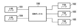
図1は、ソフトウェア定義ネットワーク(SDN)ボックス106、上流ノード101および104ならびに下流ノード102、103および105を有するコンピュータシステムのシステムアーキテクチャの一実施形態を示すブロック図である。各構成要素は、ネットワーク(それだけではないが、たとえばイーサネット)によって接続されている。一般に、システムには少なくとも1つのグループがある。図1には2つのグループがある。1つのグループは、上流ノード101および下流ノード102および下流ノード103から成る。他のグループは上流ノード104および下流ノード105から成る。各グループに、単一の上流ノードと、少なくとも1つの下流ノードとがある。上流ノードと下流ノードの間のすべてのパケットはSDNボックスによって転送される。
<System components>
FIG. 1 is a block diagram illustrating one embodiment of a system architecture of a computer system having a software defined network (SDN)
<可能な実装形態のシステムアーキテクチャ>
図2Aおよび図2Bは、SDNボックスが少なくとも1つのソフトウェア定義スイッチ(SDスイッチ)と少なくとも1つのソフトウェア定義スイッチのコントローラ(SDSWコントローラ)とから成る、1つの可能な実装形態のシステムアーキテクチャの一実施形態を示すブロック図である。
<System architecture of possible implementations>
2A and 2B illustrate one embodiment of a system architecture of one possible implementation where the SDN box consists of at least one software defined switch (SD switch) and at least one software defined switch controller (SDSW controller). FIG.
図2Aにおいて、SDNボックス206はSDスイッチ208およびSDSWコントローラ207から成る。SDスイッチ208とSDSWコントローラ207の間に通信チャネルがある。上流ノードと下流ノードは2つのグループに分割され得て、各グループは単一の上流ノードおよび少なくとも1つの下流ノードから成る。上流ノード201ならびに2つの下流ノード202および203は、それぞれSDスイッチ208の第1のポート(#1)、第2のポート(#2)および第3のポート(#3)に接続されている。上流ノード204および下流ノード205は、それぞれSDスイッチ208の第4のポート(#4)および第5のポート(#5)に接続されている。
In FIG. 2A, the
図2Bにおいて、SDNボックス206は、SDスイッチ208、209、211および212、ならびにSDSWコントローラ207および210から成る。SDSWコントローラ207とSDスイッチ208の間、およびSDSWコントローラ207とSDスイッチ209の間にそれぞれ通信チャネルがある。さらに、SDSWコントローラ210とSDスイッチ211の間、およびSDSWコントローラ210とSDスイッチ212の間にもそれぞれ通信チャネルがある。上流ノードと下流ノードは2つのグループに分割され得て、各グループは単一の上流ノードおよび少なくとも1つの下流ノードから成る。上流ノード201ならびに2つの下流ノード202および203が1つのグループに属し、上流ノード204および下流ノード205が別のグループに属する。
In FIG. 2B, the
図2Aおよび図2Bにおいて、すべてのSDスイッチが、(それだけではないが)たとえばイーサネットといった特定のネットワークによって接続されている。SDSWコントローラとSDスイッチの間の通信は、(それだけではないが)たとえばOpenFlowといった特定のプロトコルにおけるものである。 In FIGS. 2A and 2B, all SD switches are connected by a specific network, such as, but not limited to, Ethernet. The communication between the SDSW controller and the SD switch is (but not only) in a specific protocol such as OpenFlow.
図3は、上流ノードのシステムアーキテクチャの一実施形態を示すブロック図である。一般に、コンピュータシステムは、CPU、メモリ、ハードディスクおよび様々なI/Oデバイスから成る。システムアーキテクチャについてより明瞭に説明するために、ここではその他の構成要素が省略されている。上流ノード301は、少なくとも中央処理装置(CPU)302、カプセル化/デカプセル化(ENCAP/DECAP)モジュール303およびネットワークインターフェースカード(NIC)304から成る。CPU 302は、基本的動作、算術演算、論理演算、およびシステムの入出力動作を遂行することにより、コンピュータプログラムの命令を実行するハードウェア構成要素である。NIC 304は、上流ノード301を、SDNボックスが配置されているネットワークに接続するハードウェア構成要素である。カプセル化/デカプセル化モジュール303は、通信プロセス中の、PCI-Eパケットのカプセル化と、受信したカプセル化されたパケットのデカプセル化とを担当している。CPU 302とカプセル化/デカプセル化モジュール303は論理的に接続されており、カプセル化/デカプセル化モジュール303とNIC 304はそれぞれ接続されている。言い換えれば、接続するやり方は制限されず、(それだけではないが)たとえばPCI-Eバスプロトコルといったハードウェアのやり方、または任意のソフトウェアのやり方のいずれかでよい。
FIG. 3 is a block diagram illustrating one embodiment of an upstream node system architecture. In general, a computer system consists of a CPU, memory, hard disk and various I / O devices. Other components are omitted here for a clearer description of the system architecture. The
図4は、下流ノードのシステムアーキテクチャの一実施形態を示すブロック図である。下流ノードはCPU、メモリ、ハードディスクおよび様々なデバイスから成り得る。システムアーキテクチャについてより明瞭に説明するために、ここではその他の構成要素が省略されている。下流ノード401は、少なくともメモリ402、カプセル化/デカプセル化(ENCAP/DECAP)モジュール403およびネットワークインターフェースカード(NIC)404から成る。NIC 404は、下流ノード401を、SDNボックスが配置されているネットワークに接続するハードウェア構成要素である。カプセル化/デカプセル化モジュール403は、通信プロセス中の、PCI-Eパケットのカプセル化と、受信したカプセル化されたパケットのデカプセル化とを担当している。メモリ402とカプセル化/デカプセル化モジュール403は接続されており、カプセル化/デカプセル化モジュール403とNIC 404は、それぞれ論理的に接続されている。言い換えれば、接続するやり方は制限されず、(それだけではないが)たとえばPCI-Eバスプロトコルといったハードウェアのやり方、または任意のソフトウェアのやり方のいずれかでよい。
FIG. 4 is a block diagram illustrating one embodiment of a downstream node system architecture. Downstream nodes can consist of CPU, memory, hard disk and various devices. Other components are omitted here for a clearer description of the system architecture. The
<SDNボックス内のパケット処理>
図5は、ソフトウェア定義(SD)スイッチのシステムアーキテクチャの一実施形態を示すブロック図である。SDスイッチ501は、少なくともRecvDモジュール502、SendDモジュール503、SendC(制御プレーンに送信する)モジュール504、RecvC(制御プレーンから受信する)モジュール509、デカプセル化(DECAP)モジュール505、カプセル化(ENCAP)モジュール506、パケットバッファ(PKT BUFFER)モジュール507およびスレーブトランザクションレイヤパケット(TLP)ルーティング表操作モジュール508から成る。RecvDモジュール502は、上流ノードおよび下流ノードからの受信を担当している。SendDモジュール503は上流ノードおよび下流ノードへの送信を担当している。RecvCモジュール509はSDSWコントローラからの受信を担当している。SendCモジュール504はSDSWコントローラへの送信を担当している。デカプセル化モジュール505は、カプセル化されたパケットをPCI-Eパケットへとデカプセル化する。カプセル化モジュール506はPCI-Eパケットをカプセル化する。パケットバッファモジュール507はパケットのバッファリングを担当している。TLPルーティング表操作モジュール508は、新規のスレーブTLPルーティング表の項目を生成して挿入することができ、スレーブTLPルーティング表の検索機能をサポートする。
<Packet processing in SDN box>
FIG. 5 is a block diagram illustrating one embodiment of a software-defined (SD) switch system architecture. The
図6は、ソフトウェア定義スイッチのコントローラ(SDSWコントローラ)のシステムアーキテクチャの一実施形態を示すブロック図である。SDSWコントローラは、少なくともRecvSWモジュール602、SendSWモジュール603、マスタTLPルーティング表操作モジュール604、およびmsgパーサモジュール605から成る。RecvSWモジュール602はSDスイッチからの受信を担当している。SendSWモジュール603はSDスイッチへの送信を担当している。マスタTLPルーティング表操作モジュール604は、新規のマスタTLPルーティング表の項目を生成して挿入することができ、マスタTLPルーティング表の検索機能をサポートする。msgパーサモジュール605が抽出する情報は、1)ノードID(ノードの固有のID)と、2)ノードのタイプ(上流ノードまたは下流ノード)と、3)各ノードの(上流または下流の)送付先アドレスと、4)ノードに接続されているSDスイッチの(上流または下流の)ポート番号と、5)グループに対して用いられるVLANタグ(基礎をなすネットワークがイーサネットであるときのみ必要)と、6)図13に示される、受信したパケットからのTLPルーティングID(TLPルーティングの固有のID)とを含む。
FIG. 6 is a block diagram illustrating an embodiment of a system architecture of a controller (SDSW controller) for a software defined switch. The SDSW controller includes at least a
SDNボックスは、少なくとも1つのSDSWコントローラおよび少なくとも1つのSDスイッチから成る。全体の処理プロセスは以下の通りである。カプセル化されたパケット(その内部のパケットはPCI-Eパケットである)がSDスイッチ501のRcevDモジュール502によって受信されると、デカプセル化モジュール505によってPCI-Eパケットへとデカプセル化され、それからTLPルーティングIDが抽出される。次いで、スレーブTLPルーティング表操作モジュール508が、抽出されたTLPルーティングIDに基づいてスレーブTLPルーティング表を回復することになる。
> 見つからない場合には、パケットはパケットバッファモジュール507においてバッファリングされ、次いで、クエリパケット(TLPルーティングID、ノードタイプ、ノードID、ならびに図13に示されるような他の関連情報を含有している)が、クエリ(SendC)モジュール504によってSDSWコントローラ601へ送信されることになる。SDSWコントローラ601の側において、クエリが、受信(RecvSW)モジュール602によって受信される。SDSWコントローラ601のマスタTLPルーティング表は、マスタTLPルーティング表操作モジュール604によって、TLPルーティングIDに基づいてさらに回復されることになる。
◇ 見つからない場合には、SDSWコントローラ601のマスタTLPルーティング表操作モジュール604は、msgパーサモジュール605によって抽出された情報に基づいて、1)ノードID(ノードの固有のID)と、2)ノードのタイプ(上流ノードまたは下流ノード)と、3)各ノードの(上流または下流の)送付先アドレスと、4)ノードに接続されているSDスイッチの(上流または下流の)ポート番号と、5)グループに対して用いられるVLANタグ(基礎をなすネットワークがイーサネットであるときのみ必要)と、6)図13に示されるTLPルーティングID(TLPルーティングの固有のID)とを含む新規の表項目を生成することになる。次いで、それがマスタTLPルーティング表に挿入される。SDSWコントローラ601の送信(SendSW)モジュール603は、PCI-E-over-EthernetパケットをブロードキャストするようにSDスイッチ501に通知することになる。
◇ 見つかった場合には、SDSWコントローラ601の送信(SendSW)モジュール603は、カプセル化されたPCI-Eパケットを、回復された送付先アドレスに従って転送するようにSDスイッチ501に通知することになる。この通知はRecvCモジュール509において処理され、同一の新規の表項目が、SDスイッチ501のスレーブTLPルーティング表操作モジュール508によって、スレーブTLPルーティング表に挿入される。
> 見つかった場合には、PCI-Eパケットは、カプセル化モジュール506によってカプセル化パケットヘッダとともにカプセル化されることになり、カプセル化パケットヘッダは、スレーブTLPルーティング表操作モジュール508によって戻される送付先アドレスとして回復されたアドレスで満たされている。
The SDN box consists of at least one SDSW controller and at least one SD switch. The overall processing process is as follows. When an encapsulated packet (its internal packet is a PCI-E packet) is received by the
> If not found, the packet is buffered in the
◇ If not found, the master TLP routing
If found, the send (SendSW)
> If found, the PCI-E packet will be encapsulated by the
<DEVINFOパケットフォーマット>
上流ノードと下流ノードの間の全体の通信プロセス中、2種類のパケットが用いられる。一方はPCI-Eパケットであり、メモリのリード/ライト、I/Oのリード/ライト、コンフィグのリード/ライトの動作中に用いられる。他方は、本発明において新しく定義された、DEVINFOパケットと称されるものである。DEVINFOパケットは、1)上流ノードと下流ノードの間の通信を開始すること、および、2)一定間隔で周期的に、上流ノードと下流ノードに互いの存続を気付かせること、のために用いられる。DEVINFOのパケットフォーマットは、(それだけではないが)少なくとも、1)ノードID(ノードの固有のID)と、2)ノードのタイプ(上流ノードまたは下流ノード)と、3)(上流または下流の)ノードのソースアドレスと、4)TLPルーティングID(TLPルーティングにおいて用いられる固有のID)とのデータフィールドを含有している。図7は、DEVINFOパケットのパケットフォーマットの可能な定義の一実施形態を示す表である。
<DEVINFO packet format>
Two types of packets are used during the entire communication process between the upstream and downstream nodes. One is a PCI-E packet, which is used during memory read / write, I / O read / write, and config read / write operations. The other is a DEVINFO packet newly defined in the present invention. DEVINFO packets are used for 1) initiating communication between upstream and downstream nodes, and 2) periodically making upstream and downstream nodes aware of each other's existence at regular intervals. . The packet format of DEVINFO is (but not only) at least 1) node ID (node unique ID), 2) node type (upstream node or downstream node), and 3) node (upstream or downstream) Data field of 4) TLP routing ID (unique ID used in TLP routing). FIG. 7 is a table illustrating one embodiment of possible definitions of the packet format of the DEVINFO packet.
<上流ノードと下流ノードの間の通信>
図8は、上流ノード801、SDNボックス802および下流ノード803の間のメモリのリード/ライトのシーケンス図である(I/Oのリード/ライトおよびコンフィグのリード/ライトのプロセスは同一のシーケンスを辿るので省略されている)。通信プロセスは以下の通りである。
(1)上流ノード801は、下流ノード803のメモリにアクセスするとき(たとえばメモリのリード/ライト動作)、PCI-Eパケットを送信する。ステップ804において、PCI-Eパケットは、カプセル化/デカプセル化モジュール303によってパケットヘッダとともにカプセル化されて、NIC 304から送出される。
(2)カプセル化されたパケットが、SDNボックス802におけるSDスイッチの特定のポートに到達する。ステップ805において、カプセル化されたパケットがデカプセル化され、次いで、ステップ806においてそれらの内部情報が抽出される。次いで、ステップ807において、デカプセル化されたパケットがカプセル化されて下流ノード803へ転送される。
(3)カプセル化されたパケットは、下流ノード803において受信されると、ステップ808においてPCI-Eパケットへとデカプセル化される。
<Communication between upstream and downstream nodes>
FIG. 8 is a sequence diagram of memory read / write between the
(1) The
(2) The encapsulated packet reaches a specific port of the SD switch in the SDN box 802. In
(3) When the encapsulated packet is received by the
下流ノードから上流ノードへの通信プロセス(たとえばメモリリードの結果に対する返答)は、上記のステップと同一である。図は省略されている。 The communication process from the downstream node to the upstream node (for example, a response to the result of the memory read) is the same as the above steps. The figure is omitted.
図9は、上流ノードまたは下流ノードがPCI-Eパケットを送出するやり方の一実施形態を示す流れ図である。
(1)ノード(上流ノードまたは下流ノードのいずれか)がステップ901においてパケットを送出しようとするとき、ステップ902においてそれがDEVINFOパケットであれば、ステップ903において、(カプセル化パケットヘッダの)送付先アドレスはブロードキャストアドレスでなければならない。
(2)送付先アドレスがブロードキャストアドレスでなければ、それは必ずPCI-Eパケットであり、(カプセル化パケットヘッダにおける)送付先アドレスは所定のフォーマットでなければならず、ステップ904においてSDスイッチによって認識され得る。
(3)最終的に、パケットは外側のパケットヘッダとともにカプセル化され、送付先アドレスはステップ903およびステップ904から生じる。外側のパケットヘッダのタイプは、基礎をなすネットワークに依拠するものである。たとえば基礎をなすネットワークがイーサネットであれば、イーサネットのパケットヘッダが外側のパケットヘッダとして追加されてステップ905で送出される。
FIG. 9 is a flow diagram illustrating one embodiment of how upstream or downstream nodes send PCI-E packets.
(1) When a node (either upstream node or downstream node) tries to send a packet in step 901, if it is a DEVINFO packet in
(2) If the destination address is not a broadcast address, it must be a PCI-E packet, and the destination address (in the encapsulated packet header) must be in a predetermined format and is recognized by the SD switch in
(3) Finally, the packet is encapsulated with the outer packet header and the destination address comes from
図10は、上流ノードまたは下流ノードがカプセル化されたパケットを受信するやり方の一実施形態を示す流れ図である。
(1)ステップ1001において、カプセル化されたパケットを受信すると、ステップ1002において、パケットがPCI-Eパケットへとデカプセル化されることになる。
FIG. 10 is a flow diagram illustrating one embodiment of how upstream or downstream nodes receive encapsulated packets.
(1) When an encapsulated packet is received in
図11は、SDスイッチが、カプセル化されたパケットを処理するやり方の一実施形態を示す流れ図である。SDスイッチのプロセスは以下の通りである。
(1)ステップ1101において、SDSWコントローラからのパケットがなければ、ステップ1104において、パケットが特定のカプセル化されたパケットに属するものであるかどうかチェックされる。パケットが特定のカプセル化されたパケットに属するものでなければ、ステップ1105において、パケットは他のパケットのルーチンにおいてさらに処理されることになる。
(2)パケットが上流ノードまたは下流ノードからのカプセル化されたパケットであれば、ステップ1106において、そのTLPルーティングIDが抽出され、それに基づいてスレーブTLPルーティング表が回復されることになる。見つからない場合には、ステップ1108においてパケットがバッファリングされ、SDSWコントローラに対してクエリ要求が送信される。見つかった場合には、ステップ1107において、パケットが、回復されたアドレスを送付先アドレスとして満たされたカプセル化ヘッダとともにカプセル化されて送出されることになる。
(3)ステップ1101において、SDSWコントローラから受信したパケットがある場合、ステップ1102において、搬送されるTLPルーティング情報が抽出され、ステップ1103において、スレーブルーティング表に新規の表項目を追加する。次いで、ステップ1107において、以前のバッファリングされたパケットがさらに処理されることになる(パケットをカプセル化し、回復された送付先アドレスを満たして、それを送信する)。
FIG. 11 is a flow diagram illustrating one embodiment of how the SD switch processes encapsulated packets. The SD switch process is as follows.
(1) If there is no packet from the SDSW controller in
(2) If the packet is an encapsulated packet from an upstream node or a downstream node, the TLP routing ID is extracted in step 1106, and the slave TLP routing table is recovered based on the extracted TLP routing ID. If not found, the packet is buffered in
(3) If there is a packet received from the SDSW controller in
図12は、SDSWコントローラが、SDスイッチからのクエリ要求を処理し、TLP情報を抽出してマスタTLPルーティング表を更新し、最終的に、スレーブTLPルーティング表を更新するようにSDスイッチに通知するやり方の一実施形態を示す流れ図である。プロセスは以下の通りである。
(1)ステップ1201において、SDスイッチからのクエリ要求パケットが受信されている場合、ステップ1202においてTLPルーティング情報が抽出されることになる。
(2)ステップ1203において、TLPルーティング情報に基づいてマスタTLPルーティング表が回復されることになる。何も見つからなければ、ステップ1204において、マスタTLPルーティング表に新規の項目が追加されることになる。
(3)最終的に、ステップ1205において、SDスイッチに通知するために回復の結果が送出される。
Figure 12 shows that the SDSW controller processes the query request from the SD switch, extracts the TLP information, updates the master TLP routing table, and finally notifies the SD switch to update the slave TLP routing table. 6 is a flow diagram illustrating one embodiment of a manner. The process is as follows.
(1) If a query request packet from the SD switch is received in step 1201, TLP routing information is extracted in step 1202.
(2) In
(3) Finally, in
図13は、TLPルーティング表の可能なデータ構造であり、これは、基礎をなすネットワークがイーサネットであるとき、SDスイッチとSDSWコントローラの両方に対して用いられる。表は、1)ノードID(ノードの固有のID)の列と、2)ノードのタイプ(上流ノードまたは下流ノード)の列と、3)各ノードの(上流または下流の)送付先アドレスの列と、4)ノードに接続されているSDスイッチの(上流または下流の)ポート番号の列と、5)グループに対して用いられるVLANタグ(基礎をなすネットワークがイーサネットであるときのみ必要)の列と、6)TLPルーティングID(TLPルーティングの固有のID)の列とから成る。図13は、VLAN IDが1または2であるノードの2つのグループを示す。最初の3つの項目は、同一のVLAN ID 1を共有するので1つのグループに属する。ノードIDが1であるノードは上流ノードであり、そのMACアドレスはMAC_00である。ノードIDが1であるノードは、SDスイッチの第1のポートに接続され、TLP IDはbusO/devO/funcOである。ノードIDが2であるノードは下流ノードであり、そのMACアドレスはMAC_01である。ノードIDが2であるノードは、SDスイッチの第2のポートに接続され、TLP IDはbusl/devl/funclである。
FIG. 13 is a possible data structure for the TLP routing table, which is used for both the SD switch and the SDSW controller when the underlying network is Ethernet. The table shows 1) the node ID (node unique ID) column, 2) the node type (upstream or downstream node) column, and 3) the destination address column (upstream or downstream) of each node. And 4) a column of port numbers (upstream or downstream) of the SD switch connected to the node, and 5) a column of VLAN tags (needed only when the underlying network is Ethernet) used for the group And 6) a column of TLP routing ID (a unique ID of TLP routing). FIG. 13 shows two groups of nodes with
<障害検知およびハンドオーバ>
図14は、上流ノード1401、SDスイッチ(たとえば、それだけではないがOpenFlowスイッチ)1402、SDSWコントローラ(たとえば、それだけではないがOpenFlowコントローラ)1403および下流ノード(明瞭な説明のために省略されている)の間の障害検知およびハンドオーバのシーケンス図である。障害検知およびハンドオーバのプロセスは以下の通りである。
(1)一旦、ステップ1404において上流ノード1401に障害があると、リンクダウンネットワーク信号がSDスイッチ1402に送信されることになる。
(2)SDスイッチ1402は、リンクダウンネットワーク信号を受信すると、ステップ1405においてSDSWコントローラ1403に通知することになる。例のために、OpenFlowにおいて、OpenFlowスイッチはOpenFlowコントローラへOFPPS_LINK_DOWNメッセージを送信することになる。
(3)SDSWコントローラ1403は、SDスイッチ1402から通知を受信すると、ステップ1406において、ハンドオーバのための別の有効な上流ノードを見つけ、ステップ1407において、接続されている下流ノードのマスタTLPルーティング表を変更し、次いで、ステップ1408においてSDスイッチに通知することになる。
(4)SDスイッチ1402は、SDSWコントローラ1403から通知を受信すると、ステップ1409においてスレーブTLPルーティング表を変更することになる。その結果、接続されている下流ノードは、新規のグループIDとともに上流ノードにハンドオーバされる。
<Fault detection and handover>
FIG. 14 shows an
(1) Once there is a failure in the
(2) When receiving the link down network signal, the
(3) Upon receiving the notification from the
(4) When receiving the notification from the
本発明の好ましい実施形態が上記で説明され、図示されてきたが、これらは本発明の例示であり、限定するものと見なされるべきではないことを理解されたい。本発明の範囲から逸脱することなく、追加、省略、置換、および他の変更が可能である。したがって、本発明は前述の説明によって限定されるものと見なされるべきではなく、添付の特許請求の範囲の有効範囲によってのみ限定されるものである。 While preferred embodiments of the present invention have been described and illustrated above, it should be understood that these are illustrative of the invention and are not to be considered as limiting. Additions, omissions, substitutions, and other changes can be made without departing from the scope of the invention. Accordingly, the invention is not to be seen as limited by the foregoing description, but is only limited by the scope of the appended claims.
101 上流ノード
102 下流ノード
103 下流ノード
104 上流ノード
105 下流ノード
106 ソフトウェア定義ネットワーク(SDN)ボックス
201 上流ノード
202 下流ノード
203 下流ノード
204 上流ノード
205 下流ノード
206 SDNボックス
207 SDSWコントローラ
208 SDスイッチ
209 SDスイッチ
210 SDSWコントローラ
211 SDスイッチ
212 SDスイッチ
301 上流ノード
302 中央処理装置(CPU)
303 カプセル化/デカプセル化(ENCAP/DECAP)モジュール
304 ネットワークインターフェースカード(NIC)
401 下流ノード
402 メモリ
403 カプセル化/デカプセル化(ENCAP/DECAP)モジュール
404 ネットワークインターフェースカード(NIC)
501 SDスイッチ
502 RecvDモジュール
503 SendDモジュール
504 SendC(制御プレーンに送信する)モジュール
505 デカプセル化(DECAP)モジュール
506 カプセル化(ENCAP)モジュール
507 パケットバッファ(PKT BUFFER)モジュール
508 スレーブトランザクションレイヤパケット(TLP)ルーティング表操作モジュール
509 RecvC(制御プレーンから受信する)モジュール
601 ソフトウェア定義スイッチのコントローラ(SDSWコントローラ)
602 RecvSWモジュール
603 SendSWモジュール
604 マスタTLPルーティング表操作モジュール
801 上流ノード
802 SDNボックス
803 下流ノード
1401 上流ノード
1402 SDスイッチ
1403 SDSWコントローラ
101 upstream node
102 Downstream node
103 Downstream node
104 upstream node
105 Downstream node
106 Software Defined Network (SDN) box
201 upstream node
202 Downstream node
203 Downstream node
204 Upstream node
205 Downstream node
206 SDN box
207 SDSW controller
208 SD switch
209 SD switch
210 SDSW controller
211 SD switch
212 SD switch
301 upstream node
302 Central processing unit (CPU)
303 Encapsulation / Decapsulation (ENCAP / DECAP) module
304 Network interface card (NIC)
401 Downstream node
402 memory
403 Encapsulation / Decapsulation (ENCAP / DECAP) module
404 Network interface card (NIC)
501 SD switch
502 RecvD module
503 SendD module
504 SendC (send to control plane) module
505 DECAP module
506 Encapsulation (ENCAP) module
507 packet buffer (PKT BUFFER) module
508 Slave Transaction Layer Packet (TLP) Routing Table Manipulation Module
509 RecvC (receive from control plane) module
601 Software-defined switch controller (SDSW controller)
602 RecvSW module
603 SendSW module
604 Master TLP routing table manipulation module
801 upstream node
802 SDN box
803 Downstream node
1401 upstream node
1402 SD switch
1403 SDSW controller
Claims (9)
前記SDNボックスによって、前記ネットワークを介して、前記上流ノードと前記下流ノードを相互に接続するステップと、
前記上流ノードと前記下流ノードの一方の側においてPCI-Eパケットを送信するステップと、
前記PCI-Eパケットを特定のパケットヘッダとともにカプセル化するステップと、
前記SDNボックスによって、内部PCI-Eパケットとともに搬送されたトランザクションレイヤパケット(TLP)ルーティング識別子(ID)に基づいて、前記カプセル化されたパケットを前記ネットワークへ送信するステップと、
前記上流ノードと前記下流ノードの他方の側において、前記カプセル化されたパケットを受信するステップと、
受信したパケットから前記特定のパケットヘッダを除去するステップと、
前記受信したパケットを前記PCI-Eパケットへとデカプセル化するステップとを含む方法。 A method of using a software defined network (SDN) box as a peripheral component interconnect express (PCI-E) switch across a network including at least one upstream node, at least one downstream node and an SDN box, comprising:
Connecting the upstream node and the downstream node to each other via the network by the SDN box;
Transmitting a PCI-E packet on one side of the upstream node and the downstream node;
Encapsulating the PCI-E packet with a specific packet header;
Sending the encapsulated packet to the network based on a transaction layer packet (TLP) routing identifier (ID) carried by the SDN box along with an internal PCI-E packet;
Receiving the encapsulated packet on the other side of the upstream node and the downstream node;
Removing the specific packet header from the received packet;
Decapsulating the received packet into the PCI-E packet.
前記下流ノードが、I/Oデバイス、ネットワークインターフェースカード(NIC)およびカプセル化/デカプセル化モジュールを含む請求項1に記載の方法。 The upstream node includes a processing unit (CPU), a network interface card (NIC) and an encapsulation / decapsulation module,
The method of claim 1, wherein the downstream node comprises an I / O device, a network interface card (NIC) and an encapsulation / decapsulation module.
前記TLPルーティング表の中に送付先アドレスが見つかった場合、前記パケットをパケットヘッダとともにカプセル化し、前記送付先アドレスを満たして送出し、
前記TLPルーティング表の中に送付先アドレスが見つからない場合、前記パケットをバッファリングして、前記SDSWコントローラに対してクエリを送出するステップと、
前記SDSWコントローラを用いて、前記SDスイッチからの前記クエリ要求を解析し、TLPルーティング情報を抽出し、前記TLPルーティング情報を新規の表項目として前記マスタTLPルーティング表に追加して、前記SDスイッチに、前記スレーブTLPルーティング表を更新するように通知するステップとを含む請求項5に記載の方法。 Decapsulating the received packet from one of the upstream node and the downstream node using an SD switch, extracting the TLP routing ID, and recovering the slave TLP routing table based on the TLP routing ID There,
When a destination address is found in the TLP routing table, the packet is encapsulated with a packet header, and the destination address is satisfied and sent.
If the destination address is not found in the TLP routing table, buffering the packet and sending a query to the SDSW controller;
Using the SDSW controller, the query request from the SD switch is analyzed, TLP routing information is extracted, the TLP routing information is added to the master TLP routing table as a new table item, and the SD switch is added to the SD switch. And notifying the slave TLP routing table to be updated.
Applications Claiming Priority (1)
| Application Number | Priority Date | Filing Date | Title |
|---|---|---|---|
| PCT/JP2014/058146 WO2015141014A1 (en) | 2014-03-18 | 2014-03-18 | Method of constructing software-defined pci express (pci-e) switch |
Publications (1)
| Publication Number | Publication Date |
|---|---|
| JP2017511532A true JP2017511532A (en) | 2017-04-20 |
Family
ID=54144014
Family Applications (1)
| Application Number | Title | Priority Date | Filing Date |
|---|---|---|---|
| JP2016555801A Pending JP2017511532A (en) | 2014-03-18 | 2014-03-18 | Method for configuring a software defined PCI Express (PCI-E) switch |
Country Status (2)
| Country | Link |
|---|---|
| JP (1) | JP2017511532A (en) |
| WO (1) | WO2015141014A1 (en) |
Families Citing this family (3)
| Publication number | Priority date | Publication date | Assignee | Title |
|---|---|---|---|---|
| US11086812B2 (en) * | 2015-12-26 | 2021-08-10 | Intel Corporation | Platform environment control interface tunneling via enhanced serial peripheral interface |
| CN108512758B (en) * | 2018-03-07 | 2021-09-14 | 华为技术有限公司 | Message processing method, controller and forwarding equipment |
| US11005782B2 (en) | 2019-04-26 | 2021-05-11 | Dell Products L.P. | Multi-endpoint adapter/multi-processor packet routing system |
Citations (3)
| Publication number | Priority date | Publication date | Assignee | Title |
|---|---|---|---|---|
| JP2007219873A (en) * | 2006-02-17 | 2007-08-30 | Nec Corp | Switch and network bridge device |
| WO2013051386A1 (en) * | 2011-10-05 | 2013-04-11 | 日本電気株式会社 | Load reduction system, and load reduction method |
| JP2014003392A (en) * | 2012-06-15 | 2014-01-09 | Ntt Docomo Inc | Control node and communication control method |
-
2014
- 2014-03-18 WO PCT/JP2014/058146 patent/WO2015141014A1/en active Application Filing
- 2014-03-18 JP JP2016555801A patent/JP2017511532A/en active Pending
Patent Citations (3)
| Publication number | Priority date | Publication date | Assignee | Title |
|---|---|---|---|---|
| JP2007219873A (en) * | 2006-02-17 | 2007-08-30 | Nec Corp | Switch and network bridge device |
| WO2013051386A1 (en) * | 2011-10-05 | 2013-04-11 | 日本電気株式会社 | Load reduction system, and load reduction method |
| JP2014003392A (en) * | 2012-06-15 | 2014-01-09 | Ntt Docomo Inc | Control node and communication control method |
Also Published As
| Publication number | Publication date |
|---|---|
| WO2015141014A1 (en) | 2015-09-24 |
Similar Documents
| Publication | Publication Date | Title |
|---|---|---|
| US10778464B2 (en) | NSH encapsulation for traffic steering establishing a tunnel between virtual extensible local area network (VxLAN) tunnel end points (VTEPS) using a NSH encapsulation header comprising a VxLAN header whose VNI field has been replaced by an NSH shim | |
| US10684885B2 (en) | Port mirroring in a virtualized computing environment | |
| US10237177B2 (en) | Transfer device and transfer system | |
| WO2018120798A1 (en) | Vxlan packet processing method, device and system | |
| US8908704B2 (en) | Switch with dual-function management port | |
| US10193707B2 (en) | Packet transmission method and apparatus | |
| CN110022264B (en) | Method for controlling network congestion, access device and computer readable storage medium | |
| KR102342286B1 (en) | DCN message processing method, network device, and network system | |
| EP2843906B1 (en) | Method, apparatus, and system for data transmission | |
| US9703747B2 (en) | Remote console access of port extenders using protocol extension | |
| CN111682927B (en) | Message synchronization method, device, equipment and medium based on MLAG environment | |
| US20160330167A1 (en) | Arp Implementation Method, Switch Device, and Control Device | |
| CN103888386A (en) | Extensible virtual local area network message transmission method, device and system | |
| CN109412922B (en) | Method, forwarding device, controller and system for transmitting message | |
| WO2018188663A1 (en) | Method and device for information notification | |
| US20190158627A1 (en) | Method and device for generating forwarding information | |
| US7860027B2 (en) | Extending an IP everywhere network over a plurality of flooding domains | |
| WO2017157318A1 (en) | Link discovery method and apparatus | |
| CN107770027B (en) | Implementation method for providing GRE tunnel service based on OpenStack architecture | |
| EP3038296A1 (en) | Pool element status information synchronization method, pool register and pool element | |
| CN106100960B (en) | Method, device and system for Fabric intercommunication of cross-storage area network | |
| JP2017511532A (en) | Method for configuring a software defined PCI Express (PCI-E) switch | |
| US9036465B2 (en) | Hierarchical network with active redundant links | |
| US9819594B2 (en) | Information processing system and controlling method and controlling device for the same | |
| WO2019056239A1 (en) | Packet synchronization method and device |
Legal Events
| Date | Code | Title | Description |
|---|---|---|---|
| A131 | Notification of reasons for refusal |
Free format text: JAPANESE INTERMEDIATE CODE: A131 Effective date: 20170627 |
|
| A02 | Decision of refusal |
Free format text: JAPANESE INTERMEDIATE CODE: A02 Effective date: 20171219 |