JP2017511014A - Broadcast transmission device, operation method of broadcast transmission device, broadcast reception device, and operation method of broadcast reception device - Google Patents
Broadcast transmission device, operation method of broadcast transmission device, broadcast reception device, and operation method of broadcast reception device Download PDFInfo
- Publication number
- JP2017511014A JP2017511014A JP2016544440A JP2016544440A JP2017511014A JP 2017511014 A JP2017511014 A JP 2017511014A JP 2016544440 A JP2016544440 A JP 2016544440A JP 2016544440 A JP2016544440 A JP 2016544440A JP 2017511014 A JP2017511014 A JP 2017511014A
- Authority
- JP
- Japan
- Prior art keywords
- information
- packet
- data
- field
- transmission
- Prior art date
- Legal status (The legal status is an assumption and is not a legal conclusion. Google has not performed a legal analysis and makes no representation as to the accuracy of the status listed.)
- Pending
Links
Images


Classifications
-
- H—ELECTRICITY
- H04—ELECTRIC COMMUNICATION TECHNIQUE
- H04N—PICTORIAL COMMUNICATION, e.g. TELEVISION
- H04N21/00—Selective content distribution, e.g. interactive television or video on demand [VOD]
- H04N21/20—Servers specifically adapted for the distribution of content, e.g. VOD servers; Operations thereof
- H04N21/23—Processing of content or additional data; Elementary server operations; Server middleware
- H04N21/238—Interfacing the downstream path of the transmission network, e.g. adapting the transmission rate of a video stream to network bandwidth; Processing of multiplex streams
- H04N21/2381—Adapting the multiplex stream to a specific network, e.g. an Internet Protocol [IP] network
-
- H—ELECTRICITY
- H04—ELECTRIC COMMUNICATION TECHNIQUE
- H04L—TRANSMISSION OF DIGITAL INFORMATION, e.g. TELEGRAPHIC COMMUNICATION
- H04L1/00—Arrangements for detecting or preventing errors in the information received
- H04L1/004—Arrangements for detecting or preventing errors in the information received by using forward error control
- H04L1/0041—Arrangements at the transmitter end
-
- H—ELECTRICITY
- H04—ELECTRIC COMMUNICATION TECHNIQUE
- H04L—TRANSMISSION OF DIGITAL INFORMATION, e.g. TELEGRAPHIC COMMUNICATION
- H04L1/00—Arrangements for detecting or preventing errors in the information received
- H04L1/0078—Avoidance of errors by organising the transmitted data in a format specifically designed to deal with errors, e.g. location
- H04L1/0083—Formatting with frames or packets; Protocol or part of protocol for error control
-
- H—ELECTRICITY
- H04—ELECTRIC COMMUNICATION TECHNIQUE
- H04L—TRANSMISSION OF DIGITAL INFORMATION, e.g. TELEGRAPHIC COMMUNICATION
- H04L65/00—Network arrangements, protocols or services for supporting real-time applications in data packet communication
- H04L65/60—Network streaming of media packets
- H04L65/61—Network streaming of media packets for supporting one-way streaming services, e.g. Internet radio
- H04L65/611—Network streaming of media packets for supporting one-way streaming services, e.g. Internet radio for multicast or broadcast
-
- H—ELECTRICITY
- H04—ELECTRIC COMMUNICATION TECHNIQUE
- H04L—TRANSMISSION OF DIGITAL INFORMATION, e.g. TELEGRAPHIC COMMUNICATION
- H04L65/00—Network arrangements, protocols or services for supporting real-time applications in data packet communication
- H04L65/60—Network streaming of media packets
- H04L65/65—Network streaming protocols, e.g. real-time transport protocol [RTP] or real-time control protocol [RTCP]
-
- H—ELECTRICITY
- H04—ELECTRIC COMMUNICATION TECHNIQUE
- H04N—PICTORIAL COMMUNICATION, e.g. TELEVISION
- H04N21/00—Selective content distribution, e.g. interactive television or video on demand [VOD]
- H04N21/40—Client devices specifically adapted for the reception of or interaction with content, e.g. set-top-box [STB]; Operations thereof
- H04N21/43—Processing of content or additional data, e.g. demultiplexing additional data from a digital video stream; Elementary client operations, e.g. monitoring of home network or synchronising decoder's clock; Client middleware
- H04N21/4302—Content synchronisation processes, e.g. decoder synchronisation
- H04N21/4305—Synchronising client clock from received content stream, e.g. locking decoder clock with encoder clock, extraction of the PCR packets
-
- H—ELECTRICITY
- H04—ELECTRIC COMMUNICATION TECHNIQUE
- H04N—PICTORIAL COMMUNICATION, e.g. TELEVISION
- H04N21/00—Selective content distribution, e.g. interactive television or video on demand [VOD]
- H04N21/60—Network structure or processes for video distribution between server and client or between remote clients; Control signalling between clients, server and network components; Transmission of management data between server and client, e.g. sending from server to client commands for recording incoming content stream; Communication details between server and client
- H04N21/61—Network physical structure; Signal processing
- H04N21/6106—Network physical structure; Signal processing specially adapted to the downstream path of the transmission network
- H04N21/6112—Network physical structure; Signal processing specially adapted to the downstream path of the transmission network involving terrestrial transmission, e.g. DVB-T
-
- H—ELECTRICITY
- H04—ELECTRIC COMMUNICATION TECHNIQUE
- H04N—PICTORIAL COMMUNICATION, e.g. TELEVISION
- H04N21/00—Selective content distribution, e.g. interactive television or video on demand [VOD]
- H04N21/60—Network structure or processes for video distribution between server and client or between remote clients; Control signalling between clients, server and network components; Transmission of management data between server and client, e.g. sending from server to client commands for recording incoming content stream; Communication details between server and client
- H04N21/61—Network physical structure; Signal processing
- H04N21/6106—Network physical structure; Signal processing specially adapted to the downstream path of the transmission network
- H04N21/6125—Network physical structure; Signal processing specially adapted to the downstream path of the transmission network involving transmission via Internet
-
- H—ELECTRICITY
- H04—ELECTRIC COMMUNICATION TECHNIQUE
- H04N—PICTORIAL COMMUNICATION, e.g. TELEVISION
- H04N21/00—Selective content distribution, e.g. interactive television or video on demand [VOD]
- H04N21/60—Network structure or processes for video distribution between server and client or between remote clients; Control signalling between clients, server and network components; Transmission of management data between server and client, e.g. sending from server to client commands for recording incoming content stream; Communication details between server and client
- H04N21/63—Control signaling related to video distribution between client, server and network components; Network processes for video distribution between server and clients or between remote clients, e.g. transmitting basic layer and enhancement layers over different transmission paths, setting up a peer-to-peer communication via Internet between remote STB's; Communication protocols; Addressing
- H04N21/643—Communication protocols
- H04N21/6437—Real-time Transport Protocol [RTP]
-
- H—ELECTRICITY
- H04—ELECTRIC COMMUNICATION TECHNIQUE
- H04N—PICTORIAL COMMUNICATION, e.g. TELEVISION
- H04N21/00—Selective content distribution, e.g. interactive television or video on demand [VOD]
- H04N21/80—Generation or processing of content or additional data by content creator independently of the distribution process; Content per se
- H04N21/85—Assembly of content; Generation of multimedia applications
- H04N21/854—Content authoring
- H04N21/8547—Content authoring involving timestamps for synchronizing content
-
- H—ELECTRICITY
- H04—ELECTRIC COMMUNICATION TECHNIQUE
- H04L—TRANSMISSION OF DIGITAL INFORMATION, e.g. TELEGRAPHIC COMMUNICATION
- H04L65/00—Network arrangements, protocols or services for supporting real-time applications in data packet communication
- H04L65/60—Network streaming of media packets
- H04L65/70—Media network packetisation
Abstract
放送受信装置が開示される。本発明の一実施例によるほう送受信装置は、パケットを介した伝送の対象である伝送オブジェクトを含むパケットペイロードと前記パケットペイロードをシグナリングするパケットヘッダで区分される伝送パケットを受信する放送受信部と、前記伝送パケットから前記パケットヘッダを抽出し、前記抽出されたパケットヘッダから前記伝送オブジェクトの再生またはデコーティング時点に関する第1情報を抽出して、前記第1情報に基づいて前記伝送オブジェクトを出力する制御部と、を含む。【選択図】図78A broadcast receiving apparatus is disclosed. According to an embodiment of the present invention, a transmission / reception apparatus includes a broadcast receiving unit that receives a packet that includes a transmission object that is a transmission object through a packet and a transmission packet that is divided by a packet header that signals the packet payload; Control for extracting the packet header from the transmission packet, extracting first information related to playback or decoding time of the transmission object from the extracted packet header, and outputting the transmission object based on the first information Part. [Selection] Figure 78
Description
本発明は放送伝送装置、放送伝送装置の動作方法、放送受信装置及び放送受信装置の動作方法に関するものである。 The present invention relates to a broadcast transmission apparatus, an operation method of the broadcast transmission apparatus, a broadcast reception apparatus, and an operation method of the broadcast reception apparatus.
最近のデジタル放送は、地上波放送網を介してA/Vを受信しインターネット網を介してA/V及び向上された(Enhancement)データを受信するようにするハイブリッド放送をサポートするためのサービス及びコンテンツ伝送同期化方式を必要としている。 Recent digital broadcasts include services for supporting hybrid broadcasts that receive A / V over a terrestrial broadcast network and receive A / V and enhanced data over the Internet network, and A content transmission synchronization method is required.
特に、今後DTVサービスで活用される有力なアプリケーションのうち一つとして従来の地上波放送網と共にインターネット網との連動を介したハイブリッド放送サービスがある。ハイブリッド放送サービスは地上波放送網を介して伝送される放送コンテンツに関する向上されたデータまたは放送コンテンツの一部をインターネット網を介してリアルタイムに伝送することで、ユーザが多様なコンテンツを経験することができる。よって、放送コンテンツを地上波放送網及びインターネット網両方を介して伝送し受信する放送伝送装置と放送受信装置が必要である。 In particular, one of the promising applications to be utilized in the DTV service in the future is a hybrid broadcasting service through linkage with the Internet network together with a conventional terrestrial broadcasting network. The hybrid broadcasting service allows users to experience various contents by transmitting improved data related to broadcast contents transmitted via the terrestrial broadcast network or part of the broadcast contents in real time via the Internet network. it can. Therefore, there is a need for a broadcast transmission apparatus and a broadcast reception apparatus that transmit and receive broadcast content via both the terrestrial broadcast network and the Internet network.
本発明の実施例は、地上波放送網とインターネット網が連動する次世代ハイブリッド放送をサポートする放送伝送装置、放送伝送装置の動作方法、放送受信装置及び放送受信装置の動作方法を提供することを目的とする。 Embodiments of the present invention provide a broadcast transmission apparatus that supports next-generation hybrid broadcasting in which a terrestrial broadcast network and an Internet network are linked, an operation method of the broadcast transmission apparatus, a broadcast reception apparatus, and an operation method of the broadcast reception apparatus. Objective.
特に、本発明の一実施例は放送サービスのリアルタイムのコンテンツ伝送プロトコル上において、メディアファイルフォーマットベースのデータ伝送のための伝送パケットのペイロード(Payload)フォーマットを利用する放送伝送装置、放送伝送装置の動作方法、放送受信装置及び放送受信装置の動作方法を提供することを目的とする。 In particular, an embodiment of the present invention is a broadcast transmission apparatus that uses a payload format of a transmission packet for data transmission based on a media file format on a real-time content transmission protocol of a broadcast service, and an operation of the broadcast transmission apparatus. It is an object to provide a method, a broadcast receiving apparatus, and an operation method of the broadcast receiving apparatus.
特に、本発明の一実施例は伝送しようとするオブジェクト(Object)のタイプ(type)及びオブジェクトのタイミング情報を伝送するための伝送パケット構造を利用する放送伝送装置、放送伝送装置の動作方法、放送受信装置及び放送受信装置の動作方法を提供することを目的とする。 In particular, an embodiment of the present invention relates to a broadcast transmission apparatus that uses a transmission packet structure for transmitting the type of an object to be transmitted and the timing information of the object, a method for operating the broadcast transmission apparatus, and broadcasting. It is an object of the present invention to provide an operation method of a receiving apparatus and a broadcast receiving apparatus.
特に、本発明の一実施例は伝送しようとするオブジェクト別に相異なるタイミング情報をマッピングするための伝送パケット構造を利用する放送伝送装置、放送伝送装置の動作方法、放送受信装置及び放送受信装置の動作方法を提供することを目的とする。 In particular, an embodiment of the present invention relates to a broadcast transmission apparatus using a transmission packet structure for mapping different timing information for each object to be transmitted, a method for operating the broadcast transmission apparatus, a broadcast reception apparatus, and an operation of the broadcast reception apparatus. It aims to provide a method.
特に、本発明の一実施例は伝送パケットを流動的に構成するための伝送パケット構造を利用する放送伝送装置、放送伝送装置の動作方法、放送受信装置及び放送受信装置の動作方法を提供することを目的とする。 In particular, an embodiment of the present invention provides a broadcast transmission apparatus, a broadcast transmission apparatus operation method, a broadcast reception apparatus, and a broadcast reception apparatus operation method using a transmission packet structure for fluidly configuring transmission packets. With the goal.
本発明の一実施例による放送受信装置は、パケットを介した伝送の対象である伝送オブジェクトを含むパケットペイロードと前記パケットペイロードをシグナリングするパケットヘッダで区分される伝送パケットを受信する放送受信部と、前記伝送パケットから前記パケットヘッダを抽出し、前記抽出されたパケットヘッダから前記伝送オブジェクトの再生またはデコーティング時点に関する第1情報を抽出して、前記第1情報に基づいて前記伝送オブジェクトを出力する制御部と、を含む。 A broadcast receiving apparatus according to an embodiment of the present invention includes a broadcast receiving unit that receives a packet that includes a transmission object that is a transmission object to be transmitted via a packet and a transmission packet that is divided by a packet header that signals the packet payload; Control for extracting the packet header from the transmission packet, extracting first information related to playback or decoding time of the transmission object from the extracted packet header, and outputting the transmission object based on the first information Part.
この際、前記制御部は前記パケットヘッダから前記伝送オブジェクトのタイプを示す第2情報を取得する。 At this time, the control unit obtains second information indicating the type of the transmission object from the packet header.
この際、前記第2情報は前記伝送オブジェクトのタイプがISO BMFFベースのレギュラーファイルである第1タイプ、HTTPによるエンティティ(entity)である第2タイプ及びオーディオまたはビデオアクセスユニットである第3タイプのうち少なくとも一つである。 At this time, the second information includes a first type in which the type of the transmission object is an ISO BMFF-based regular file, a second type that is an entity by HTTP, and a third type that is an audio or video access unit. At least one.
この際、前記第1情報は前記伝送オブジェクトのタイムスタンプを含む第1時間情報及び前記第1時間情報とマッピングされる基本タイムラインのタイムスタンプを含む第2時間情報のうち少なくとも一つを含む。 At this time, the first information includes at least one of first time information including a time stamp of the transmission object and second time information including a time stamp of a basic timeline mapped to the first time information.
この際、前記パケットヘッダは前記第1時間情報とマッピングされる基本タイムラインに関するデータの位置情報を含む。 At this time, the packet header includes position information of data related to the basic timeline mapped with the first time information.
この際、前記制御部は前記パケットヘッダに前記第2時間情報が含まれているのか否かに関する情報を前記拡張されたヘッダから取得する。 At this time, the control unit acquires information on whether or not the second time information is included in the packet header from the extended header.
この際、前記制御部は前記第1時間情報のフォーマット情報及び第2時間情報のフォーマット情報のうち少なくとも一つを前記パケットヘッダから取得する。 At this time, the control unit acquires at least one of the format information of the first time information and the format information of the second time information from the packet header.
この際、前記制御部は前記第1情報及び第2情報を前記パケットヘッダの一部として、前記パケットヘッダに選択的に含まれる拡張されたヘッダから取得する。 At this time, the control unit acquires the first information and the second information as part of the packet header from an extended header that is selectively included in the packet header.
この際、前記制御部は前記パケットヘッダから前記伝送パケットの構造タイプの情報を取得する。 At this time, the control unit acquires information on the structure type of the transmission packet from the packet header.
この際、前記伝送パケットの構造タイプはパケットヘッダ、拡張されたヘッダ、ペイロード識別子及びオブジェクトデータを含む第1構造タイプ、パケットヘッダ及び拡張されたヘッダのみを含む第2構造タイプ、パケットヘッダ、拡張されたヘッダ及びオブジェクトデータのみを含む第3構造タイプを含む。 At this time, the structure type of the transmission packet includes a packet header, an extended header, a first structure type including a payload identifier and object data, a second structure type including only the packet header and the extended header, a packet header, and an extended. A third structure type that includes only header and object data.
この際、前記第1構造タイプはオブジェクトデータのオフセット情報を更に含む。 At this time, the first structure type further includes offset information of the object data.
また、本発明の一実施例による放送受信装置の動作方法は、パケットを介した伝送の対象である伝送オブジェクトのデータを含むパケットペイロードと前記パケットペイロードをシグナリングするパケットヘッダで区分される伝送パケットを受信するステップと、前記伝送パケットから前記パケットヘッダを抽出するステップと、前記抽出されたパケットヘッダから前記伝送オブジェクトの再生及びデコーティング時点に関する第1情報を取得するステップと、前記第1情報に基づいて前記伝送オブジェクトを出力するステップと、を含む。 In addition, the operation method of the broadcast receiving apparatus according to an embodiment of the present invention includes a packet that includes data of a transmission object to be transmitted via a packet, and a transmission packet that is divided by a packet header that signals the packet payload. Receiving the packet, extracting the packet header from the transmission packet, obtaining first information about playback and decoding time of the transmission object from the extracted packet header, and based on the first information And outputting the transmission object.
この際、前記動作方法は前記パケットヘッダから前記伝送オブジェクトのタイプを示す第2情報を取得するステップを更に含む。 At this time, the operation method further includes obtaining second information indicating the type of the transmission object from the packet header.
この際、前記第2情報は前記伝送オブジェクトのタイプがISO BMFFベースのレギュラーファイルである第1タイプ、HTTPによるエンティティである第2タイプ及びオーディオまたはビデオアクセスユニットである第3タイプのうち少なくとも一つである。 At this time, the second information includes at least one of a first type in which the type of the transmission object is an ISO BMFF-based regular file, a second type that is an entity based on HTTP, and a third type that is an audio or video access unit. It is.
この際、前記第1情報は前記伝送オブジェクトのタイムスタンプを含む第1時間情報及び前記第1時間情報とマッピングされる基本タイムラインのタイムスタンプを含む第2時間情報のうち少なくとも一つを含む。 At this time, the first information includes at least one of first time information including a time stamp of the transmission object and second time information including a time stamp of a basic timeline mapped to the first time information.
この際、前記パケットヘッダは前記第1時間情報とマッピングされる基本タイムラインに関するデータの位置情報を含む。 At this time, the packet header includes position information of data related to the basic timeline mapped with the first time information.
この際、前記動作方法は前記パケットヘッダに前記第2時間情報が含まれているのか否かに関する情報を前記拡張されたヘッダから取得するステップを更に含む。 At this time, the operation method further includes a step of obtaining information on whether or not the second time information is included in the packet header from the extended header.
この際、前記動作方法は前記第1情報及び第2情報を前記パケットヘッダの一部として、前記パケットヘッダに選択的に含まれる拡張されたヘッダから取得するステップを更に含む。 At this time, the operation method further includes obtaining the first information and the second information as part of the packet header from an extended header that is selectively included in the packet header.
この際、前記動作方法は前記パケットヘッダから前記伝送パケットの構造タイプの情報を取得する。 At this time, the operation method acquires the structure type information of the transmission packet from the packet header.
この際、前記伝送パケットの構造タイプはパケットヘッダ、拡張されたヘッダ、ペイロード識別子及びオブジェクトデータを含む第1構造タイプ、パケットヘッダ及び拡張されたヘッダのみを含む第2構造タイプ、パケットヘッダ、拡張されたヘッダ及びオブジェクトデータのみを含む第3構造タイプを含む。 At this time, the structure type of the transmission packet includes a packet header, an extended header, a first structure type including a payload identifier and object data, a second structure type including only the packet header and the extended header, a packet header, and an extended. A third structure type that includes only header and object data.
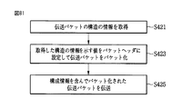
また、本発明の一実施例による放送伝送装置は、パケットを介した伝送の対象である伝送オブジェクトを取得し、前記伝送オブジェクトの再生及びデコーティング時点に関する第1情報及び前記伝送オブジェクトのタイプを示す第2情報のうち少なくとも一つを取得し、前記取得した第1情報及び第2情報のうち少なくとも一つをパケットヘッダに設定してパケット化する制御部と、前記パケット化されたデータを伝送パケットを介して伝送する伝送部と、を含む。 In addition, the broadcast transmission apparatus according to an embodiment of the present invention acquires a transmission object that is a transmission target via a packet, and indicates first information regarding playback and decoding time of the transmission object and the type of the transmission object. A controller that acquires at least one of the second information, sets at least one of the acquired first information and second information in a packet header, and packetizes the packet, and transmits the packetized data as a transmission packet And a transmission unit that transmits the data via the network.
また、本発明の一実施例による放送伝送装置の動作方法は、パケットを介した伝送の対象である伝送オブジェクトを取得するステップと、前記伝送オブジェクトの再生及びデコーティング時点に関する第1情報及び前記伝送オブジェクトのタイプを示す第2情報のうち少なくとも一つを取得するステップと、前記取得した第1情報及び第2情報をパケットヘッダに設定して伝送パケットをパケット化するステップと、前記パケット化された伝送パケットを伝送するステップと、を含む。 According to another aspect of the present invention, there is provided a broadcast transmission apparatus operating method comprising: obtaining a transmission object to be transmitted via a packet; first information regarding playback and decoding times of the transmission object; and the transmission Acquiring at least one of second information indicating an object type; setting the acquired first information and second information in a packet header to packetize a transmission packet; and packetizing the packet Transmitting a transmission packet.
本発明の一実施例は、一つの伝送パケットが一つのファイルフォーマットベースのメディアデータまたは多数のファイルフォーマットベースのメディアデータを含む場合、該当伝送パケットを効率的に伝送し受信する放送伝送装置、放送伝送装置の動作方法、放送受信装置及び放送受信装置の動作方法を提供する。 According to an embodiment of the present invention, when one transmission packet includes one file format-based media data or a plurality of file format-based media data, a broadcast transmission apparatus and a broadcasting device that efficiently transmit and receive the transmission packet Provided are an operation method of a transmission apparatus, a broadcast reception apparatus, and an operation method of the broadcast reception apparatus.
また、本発明の一実施例は、一つの伝送パケットが一つ以上のメタデータを含む場合、該当伝送パケットを効率的に伝送し受信する放送伝送装置、放送伝送装置の動作方法、放送受信装置及び放送受信装置の動作方法を提供する。 Also, according to one embodiment of the present invention, when one transmission packet includes one or more metadata, a broadcast transmission apparatus that efficiently transmits and receives the transmission packet, an operation method of the broadcast transmission apparatus, and a broadcast reception apparatus And an operation method of the broadcast receiving apparatus.
特に、本発明の一実施例は、伝送しようとするオブジェクトのタイプ及びオブジェクトのタイミング情報を伝送するための伝送パケット構造を利用する放送伝送装置、放送伝送装置の動作方法、放送受信装置及び放送受信装置の動作方法を提供する。 In particular, an embodiment of the present invention relates to a broadcast transmission apparatus, a broadcast transmission apparatus operating method, a broadcast reception apparatus, and a broadcast reception using a transmission packet structure for transmitting the type of object to be transmitted and the timing information of the object. A method of operating an apparatus is provided.
特に、本発明の一実施例は、伝送しようとするオブジェクト別に相異なるタイミング情報をマッピングするための伝送パケット構造を利用する放送伝送装置、放送伝送装置の動作方法、放送受信装置及び放送受信装置の動作方法を提供する。 In particular, an embodiment of the present invention relates to a broadcast transmission apparatus that uses a transmission packet structure for mapping different timing information for each object to be transmitted, a method of operating the broadcast transmission apparatus, a broadcast reception apparatus, and a broadcast reception apparatus. Provide a method of operation.
特に、本発明の一実施例は、伝送パケットを流動的に構成するための伝送パケット構造を利用する放送伝送装置、放送伝送装置の動作方法、放送受信装置及び放送受信装置の動作方法を提供する。 In particular, an embodiment of the present invention provides a broadcast transmission apparatus, a broadcast transmission apparatus operation method, a broadcast reception apparatus, and a broadcast reception apparatus operation method using a transmission packet structure for fluidly configuring transmission packets. .
以下、添付した図面を参照して本発明の実施例について本発明の属する技術分野における通常の知識を有する者が容易に実施し得るようにより詳しく説明する。しかし、本発明は様々な相異なる形態に実装されてもよく、ここで説明する実施例に限ることはない。そして、図面で本発明を明確に説明するために説明とは関係のない部分は省略しており、明細書全体を通して類似した部分に対しては類似した図面符号を付けている。 Hereinafter, embodiments of the present invention will be described in detail with reference to the accompanying drawings so that those skilled in the art to which the present invention pertains can easily implement the embodiments. However, the present invention may be implemented in various different forms and is not limited to the embodiments described herein. In order to clearly describe the present invention in the drawings, parts not related to the description are omitted, and like parts are denoted by like reference numerals throughout the specification.
また、ある部分がある構成要素を「含む」とする際、これは特に反対する記載がない限り、他の構成要素を除くのではなく他の構成要素を更に含むことを意味する。 In addition, when a part includes a component, this means that the component does not exclude other components but includes other components unless otherwise stated.
本発明の好ましい実施例について具体的に説明し、その例は添付した図面に示す。添付した図面を参照した以下の詳細な説明は本発明の実施例によって実現される実施例のみを示すというより、本発明の好ましい実施例を説明するためのものである。以下の詳細な説明は本発明に対する徹底した理解を提供するために細部事項を含む。しかし、本発明がこのような細部事項なしに実行可能であることは当業者にとって自明である。 Reference will now be made in detail to the preferred embodiments of the present invention, examples of which are illustrated in the accompanying drawings. The following detailed description, with reference to the accompanying drawings, is intended to illustrate the preferred embodiment of the present invention, rather than to show only the embodiment realized by the embodiment of the present invention. The following detailed description includes details to provide a thorough understanding of the present invention. However, it will be apparent to those skilled in the art that the present invention may be practiced without such details.
本発明で使用される殆どの用語は該当分野で広く使用される一般的なものから選択されているが、一部の用語は出願人によって任意に選択され、その意味は必要に応じて次の説明で詳細に述べている。よって、本発明は用語の単純な名称や意味ではなく用語の意図された意味に基づいて理解すべきである。 Most of the terms used in the present invention are selected from general terms widely used in the corresponding field, but some terms are arbitrarily selected by the applicant, and the meaning is as follows. It is described in detail in the explanation. Thus, the present invention should be understood based on the intended meaning of the term and not the simple name or meaning of the term.
本発明は次世代放送サービスに関する放送信号送信及び受信装置及びその方法を提供する。本発明の一実施例による次世代放送サービスは地上波放送サービス、モバイル放送サービス、UHD TVサービスなどを含む。本発明は一実施例によって非MIMO(non−Multiple Input Multiple Output)またはMIMO方式を介して次世代放送サービスに関する放送信号を処理する。本発明の一実施例による非MIMO方式はMISO(Multiple Input Single Output)方式、SISO(Single Input Single Output)方式などを含む。 The present invention provides an apparatus and method for transmitting and receiving broadcast signals for next-generation broadcasting services. The next generation broadcasting service according to an embodiment of the present invention includes a terrestrial broadcasting service, a mobile broadcasting service, a UHD TV service, and the like. The present invention processes a broadcast signal related to a next-generation broadcasting service through a non-MIMO (non-Multiple Input Multiple Output) or a MIMO scheme according to an embodiment. Non-MIMO schemes according to an embodiment of the present invention include a MISO (Multiple Input Single Output) scheme, a SISO (Single Input Single Output) scheme, and the like.
以下、説明の便宜上、MISOまたはMIMO方式は2つのアンテナを使用するが、本発明は2つ以上のアンテナを使用するシステムに適用される。 Hereinafter, for convenience of explanation, the MISO or MIMO scheme uses two antennas, but the present invention is applied to a system using two or more antennas.
本発明は特定用途に要求される性能を達成しながら受信器の複雑度を最小化するために最適化された3つのフィジカルプロファイル(PHY profile)(ベース(base)、ハンドヘルド(handheld)、アドバンスド(advanced)プロファイル)を定義する。フィジカルプロファイルは該当する受信器が実装すべき全てのサブセットである。 The present invention provides three physical profiles (base), handheld, advanced (optimized to minimize receiver complexity while achieving the performance required for specific applications. advanced) profile). The physical profile is all subsets that should be implemented by the corresponding receiver.
3つのフィジカルプロファイルは殆どの機能ブロックを共有するが、特定ブロック及び/またはパラメータでは多少異なる。後に追加にフィジカルプロファイルが定義されてもよい。システムの発展のために、フューチャープロファイルはFEF(future extension frame)を介して単一RF(radio frequency)チャネルに存在するプロファイルとマルチプレキシングされてもよい。各フィジカルプロファイルに関する詳細な内容は後述する。 The three physical profiles share most of the functional blocks, but are somewhat different for specific blocks and / or parameters. Additional physical profiles may be defined later. Due to the development of the system, the future profile may be multiplexed with a profile existing in a single radio frequency (RF) channel via a feature extension frame (FEF). Detailed contents regarding each physical profile will be described later.
1.ベースプロファイル 1. Base profile
ベースプロファイルは主にルーフトップ(roof−top)アンテナと連結される固定された受信装置の主な用途を示す。ベースプロファイルはある場所に移動されるが、割と停止された受信範疇に属する携帯用装置も含む。ベースプロファイルの用途は多少改善された実行によってハンドヘルド装置または車両用に拡張されるが、このような使用用途はベースプロファイル受信器の動作では期待されない。 The base profile mainly indicates the main application of a fixed receiving device coupled with a roof-top antenna. The base profile is moved to a certain location, but also includes portable devices that belong to the suspended reception category. Although the use of base profiles is extended for handheld devices or vehicles with somewhat improved implementation, such use is not expected in the operation of base profile receivers.
受信のターゲット信号対雑音比の範囲は略10乃至20dBであるが、これは従来の放送システム(例えば、ATSC A/53)の15dB信号対雑音比の受信能力を含む。受信器の複雑度及び消費電力はハンドヘルドプロファイルを使用するバッテリで駆動されるハンドヘルド装置より重要ではない。ベースプロファイルに関する重要システムパラメータを下記表1に示す。 The range of the target signal to noise ratio for reception is approximately 10 to 20 dB, which includes the reception capability of the 15 dB signal to noise ratio of conventional broadcast systems (eg, ATSC A / 53). The complexity and power consumption of the receiver is less important than a battery-powered handheld device that uses a handheld profile. The important system parameters for the base profile are shown in Table 1 below.

2.ハンドヘルドプロファイル 2. Handheld profile
ハンドヘルドプロファイルはバッテリ電源で駆動されるハンドヘルド及び車両用装置での使用のために設計される。該当装置は歩行者及び車両速度で移動する。受信器の複雑度だけでなく、消費電力ははハンドヘルドプロファイルの装置の実装のために非常に重要である。ハンドヘルドプロファイルのターゲット信号対雑音比の範囲は略0乃至10dBであるが、より低い室内受信のために意図される場合、0dBの下に達するように設定してもよい。 The handheld profile is designed for use in battery-powered handheld and vehicle equipment. The device moves at pedestrian and vehicle speeds. Power consumption as well as receiver complexity is very important for the implementation of handheld profile devices. The target signal to noise ratio range of the handheld profile is approximately 0 to 10 dB, but may be set to reach below 0 dB when intended for lower room reception.
低信号対雑音比の能力だけでなく、受信器の移動性によって現れたドップラー効果に関する復元力はハンドヘルドプロファイルの最も重要な性能属性である。ハンドヘルドプロファイルに関する重要システムパラメータを下記表2に示す。 Not only the capability of the low signal-to-noise ratio, but also the resilience regarding the Doppler effect manifested by the mobility of the receiver is the most important performance attribute of the handheld profile. The important system parameters for handheld profiles are shown in Table 2 below.
3.アドバンスドプロファイル 3. Advanced profile
アドバンスドプロファイルはより大きい実行複雑度に対する対価としてより高いチャネル能力を提供する。該当プロファイルはMIMO送信及び受信を使用することを要求し、UHD TVサービスはターゲット用途であって、そのために該当プロファイルが特別に設計される。向上された能力は与えられた帯域幅でサービス数の増加、例えば多数のSDTV及びHDTVサービスを許容するのにも使用される。 The advanced profile provides higher channel capability as a price for higher execution complexity. The corresponding profile requires the use of MIMO transmission and reception, and the UHD TV service is a target application, for which the corresponding profile is specially designed. The improved capability is also used to allow an increase in the number of services, eg a large number of SDTV and HDTV services, in a given bandwidth.
アドバンスドプロファイルのターゲット信号対雑音比は略20乃至30dBである。MIMO伝送は、初期には従来の楕円分極の伝送装備を使用し、後に全出力高次分極伝送に拡張される。アドバンスドプロファイルに関する重要システムパラメータを下記表3に示す。 The target signal-to-noise ratio of the advanced profile is approximately 20 to 30 dB. MIMO transmission initially uses conventional elliptically polarized transmission equipment and is later extended to full power higher order polarization transmission. Table 3 below shows important system parameters related to the advanced profile.
この場合、ベースプロファイルは地上波放送サービス及びモバイル放送サービス両方に対するプロファイルとして使用される。即ち、ベースプロファイルは、モバイルプロファイルを含むプロファイルの概念を定義するために使用される。また、アドバンスドプロファイルはMIMOを有するベースプロファイルに対するアドバンスドプロファイル及びMIMOを有するハンドヘルドプロファイルに対するアドバンスドプロファイルとして区分される。そして、該当3つのプロファイルは設計者の意図によって変更される。 In this case, the base profile is used as a profile for both the terrestrial broadcast service and the mobile broadcast service. That is, the base profile is used to define the concept of profiles including mobile profiles. The advanced profile is classified as an advanced profile for a base profile having MIMO and an advanced profile for a handheld profile having MIMO. Then, the corresponding three profiles are changed according to the intention of the designer.
以下の用語及び定義は本発明に適用される。以下の用語及び定義は設計に応じて変更されてもよい。 The following terms and definitions apply to the present invention. The following terms and definitions may vary depending on the design.
補助ストリーム:フューチャーエクステンション(future extension、将来の拡張)または放送局やネットワーク運営者によって要求されることで使用されるまだ定義されていない変調及びコーティングのデータを伝達するセルのシーケンス Auxiliary stream: a sequence of cells carrying future extension, or undefined modulation and coating data used as required by broadcasters and network operators
ベースデータパイプ(base data pipe):サービスシグナリングデータを伝達するデータパイプ Base data pipe: a data pipe that carries service signaling data
ベースバンドフレーム(またはBBFRAME):一つのFECエンコーディング過程(BCH及びLDPCエンコーディング)に対する入力を形成するKbchビットの集合 Baseband frame (or BBFRAME): a set of Kbch bits that form the input for one FEC encoding process (BCH and LDPC encoding)
セル(cell):OFDM伝送の一つのキャリアによって伝達される変調値 Cell: modulation value carried by one carrier in OFDM transmission
コーディングブロック(coded block):PLS1データのLDPCエンコーディングされたブロックまたはPLS2データのLDPCエンコーディングされたブロックのうち一つ Coding block: one of an LDPC encoded block of PLS1 data or an LDPC encoded block of PLS2 data
データパイプ(data pipe):一つまたは多数のサービスまたはサービスコンポーネントを伝達するサービスデータまたは関連するメタデータを伝達する物理層でのロジカルチャネル Data pipe: a logical channel in the physical layer that carries service data or related metadata that carries one or many services or service components
データパイプユニット(DPU、data pipe unit):データセルをフレームでのデータパイプに割り当てる基本ユニット Data pipe unit (DPU, data pipe unit): a basic unit that allocates data cells to data pipes in a frame
データシンボル(data symbol):プリアンブルではなくフレームでのOFDMシンボル(フレームシグナリングシンボル及びフレームエッジ(edge)シンボルはデータシンボルに含まれる)。 Data symbol: OFDM symbol in a frame, not a preamble (frame signaling symbols and frame edge symbols are included in the data symbols).
DP_ID:該当8ビットフィールドはSYSTEM_IDによって識別されたシステム内でデータパイプを唯一に識別する。 DP_ID: The corresponding 8-bit field uniquely identifies the data pipe in the system identified by the SYSTEM_ID.
ダミーセル(dummy cell):PLSシグナリング、データパイプまたは補助ストリームのために使用されていない残りの容量を詰めるのに使用される擬似ランダム値を伝達するセル Dummy cell: A cell carrying a pseudo-random value used to fill the remaining capacity not used for PLS signaling, data pipes or auxiliary streams
EAC(非常警報チャネル):EAS情報データを伝達するフレームの一部 EAC (Emergency Alarm Channel): Part of a frame carrying EAS information data
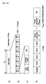
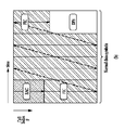
フレーム(frame):プリアンブルから始まってフレームエッジシンボルで終了される物理層タイムスロット Frame: a physical layer time slot that starts with a preamble and ends with a frame edge symbol
フレームレペティションユニット(frame repetition unit、フレーム繰り返し単位):スーパーフレーム(super−frame)で8回繰り返されるFEFを含む同じまたは異なるフィジカルプロファイルに属するフレームの集合 Frame repetition unit (frame repetition unit): a set of frames belonging to the same or different physical profiles including FEF repeated eight times in a super-frame (super-frame)
FIC(高速情報チャネル):サービスと該当ベースデータパイプの間におけるマッピング情報を伝達するフレームのロジカルチャネル FIC (Fast Information Channel): Logical channel of the frame that carries mapping information between the service and the corresponding base data pipe
FECBLOCK:データパイプのLDPCエンコーディングされたビットの集合 FECBLOCK: a set of LDPC encoded bits of a data pipe
FFTサイズ:基本周期Tのサイクルで表現されたアクティブシンボル周期Tsと同じ特定モードに使用される名目上のFFTサイズ FFT size: Nominal FFT size used in the same specific mode as the active symbol period Ts expressed by the cycle of the basic period T
フレームシグナリングシンボル(frame signaling symbol):PLSデータの一部を伝達するFFTサイズ、ガードインターバル(guard interval)及びスキャッタ(scattered)ファイルパターンの特定の組み合わせにおいて、フレームの開始に使用されるより高いパイロット密度を有するOFDMシンボル Frame signaling symbol: higher pilot density used for the start of a frame in a specific combination of FFT size, guard interval and scattered file pattern carrying part of the PLS data OFDM symbol with
フレームエッジシンボル(frame edge symbol):FFTサイズ、ガードインターバル及びスキャッタパイロットパターンの特定の組み合わせにおいて、フレームの端で使用されるより高いパイロット密度を有するOFDMシンボル Frame edge symbol: an OFDM symbol with higher pilot density used at the end of the frame in a specific combination of FFT size, guard interval and scatter pilot pattern
フレームグループ(frame−group):スーパーフレームで同じフィジカルタイプを有する全てのフレームの集合 Frame-group: a set of all frames with the same physical type in a superframe
フューチャーエクステンションフレーム(future extention frame、将来の拡張フレーム):プリアンブルで始まる、将来の拡張に使用可能なスーパーフレーム内での物理層タイムスロット Future extension frame (future extension frame): A physical layer time slot within a superframe that can be used for future extensions, starting with a preamble.
フューチャーキャスト(futurecast)UTBシステム:入力が一つ以上のMPEG2−TSまたはIP(Internet protocol)または一般ストリームであり、出力がRFシグナルである提案された物理層放送システム。 Futurecast UTB system: A proposed physical layer broadcasting system in which the input is one or more MPEG2-TS or IP (Internet protocol) or general stream and the output is an RF signal.
インプットストリーム(input stream、入力ストリーム):システムによって最終ユーザに伝達されるサービスの調和(ensemble)のためのデータのストリーム Input stream: a stream of data for the ensemble of services delivered by the system to the end user
ノーマル(normal)データシンボル:フレームシグナリングシンボル及びフレームエッジシンボルを除くデータシンボル Normal data symbol: Data symbol excluding frame signaling symbol and frame edge symbol
フィジカルプロファイル(PHY profile):該当する受信器が実装すべき全ての構造とサブセット PHY profile: all structures and subsets that the receiver should implement
PLS:PLS1及びPLS2で構成された物理層シグナリングデータ PLS: Physical layer signaling data composed of PLS1 and PLS2
PLS1:PLS2をデコーティングするのに必要なパラメータだけでなく、システムに関する基本情報を伝達する固定されたサイズ、コーディング、変調を有するFSSに伝達されるPLSデータの第1集合 PLS1: A first set of PLS data that is conveyed to the FSS with a fixed size, coding, modulation that conveys basic information about the system as well as the parameters needed to decode PLS2
NOTE:PLS1データはフレームグループのデュレーション(duration)の間に一定である。 NOTE: PLS1 data is constant during the duration of the frame group.
PLS2:データパイプ及びシステムに関するより詳細なPLSデータを伝達するFSSに伝送されるPLSデータの第2集合 PLS2: A second set of PLS data transmitted to the FSS that conveys more detailed PLS data about the data pipe and system
PLS2ダイナミック(dynamic、動的)データ:フレームごとにダイナミックに変化するPLS2データ PLS2 dynamic data: PLS2 data that dynamically changes from frame to frame
PLS2スタティック(static、静的)データ:フレームのデュレーションの間にスタティックなPLS2データ PLS2 static data: static PLS2 data during the duration of the frame
プリアンブルシグナリングデータ(preamble signaling data):プリアンブルシンボルによって伝達されてシステムの基本モードを確認するのに使用されるシグナリングデータ Preamble signaling data: Signaling data carried by a preamble symbol and used to confirm the basic mode of the system.
プリアンブルシンボル(preamble symbol):基本PLSデータを伝達し、フレームの開始に位置する固定された長さのパイロットシンボル Preamble symbol: A pilot symbol of fixed length that carries basic PLS data and is located at the start of a frame
NOTE:プリアンブルシンボルはシステム信号、そのタイミング、周波数オフセット及びFFTサイズを検出するために高速初期バンドスキャンに主に使用される。 NOTE: Preamble symbols are mainly used for fast initial band scan to detect the system signal, its timing, frequency offset and FFT size.
将来の使用(future use)のためのリザーブド(reserved):現在の文書で定義されていないが、将来に定義される可能性がある。 Reserved for future use: Not defined in the current document, but may be defined in the future.
スーパーフレーム(superframe):8つのフレーム反復単位の集合 Superframe: a set of 8 frame repeat units
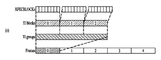
タイムインターリービングブロック(time interliving block、TI block):タイムインターリーバメモリの一つの用途に当たる、タイムインターリービングが実行されるセルの集合 Time interleaving block (TI block): A set of cells on which time interleaving is performed, which corresponds to one use of a time interleaver memory
タイムインターリービンググループ(time interliving group、TI group):整数、ダイナミックに変化するXFECBLOCKの数で形成された、特定データのパイプに対するダイナミック容量割り当てが実行される単位 Time interleaving group (TI group): an integer, a unit in which dynamic capacity allocation is performed for a pipe of specific data, formed by an integer, the number of dynamically changing XFECBLOCK
NOTE:タイムインターリービンググループは一つのフレームに直接マッピングされるか多数のフレームにマッピングされる。タイムインターリービンググループは一つ以上のタイムインターリービングブロックを含む。 NOTE: A time interleaving group is mapped directly to one frame or to many frames. The time interleaving group includes one or more time interleaving blocks.
第1タイプデータパイプ(Type 1 DP):全てのデータパイプがフレームにTDM(time division multiplexing)方式にマッピングされるフレームのデータパイプ
First type data pipe (
第2タイプデータパイプ(Type 2 DP):全てのデータパイプがフレームにFDM方式にマッピングされるフレームのデータパイプ
Second type data pipe (
XFEBLOCK:一つのLDPC FECBLOCKの全てのビットを担当するNcellsセルの集合 XFEBLOCK: A set of Ncells cells responsible for all bits of one LDPC FECBLOCK
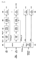
図1は、本発明の一実施例に係る次世代放送サービスに対する放送信号送信装置の構造を示す。 FIG. 1 shows a structure of a broadcast signal transmitting apparatus for a next-generation broadcast service according to an embodiment of the present invention.
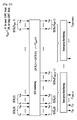
本発明の一実施例に係る次世代放送サービスに対する放送信号送信装置は、インプットフォーマットブロック(Input Format block)1000、BICM(bit interleaved coding & modulation)ブロック1010、フレームビルディングブロック(Frame building block)1020、OFDM(orthogonal frequency division multiplexing)生成ブロック(OFDM generation block)1030、及びシグナリング生成ブロック1040を含むことができる。放送信号送信装置の各ブロックの動作について説明する。
A broadcasting signal transmission apparatus for a next generation broadcasting service according to an embodiment of the present invention includes an
IPストリーム/パケット及びMPEG2-TSは、主なインプットフォーマットであり、他のストリームタイプは一般ストリームとして扱われる。これらのデータ入力に加えて、管理情報が入力されて各入力ストリームに対する該当帯域幅のスケジューリング及び割当を制御する。1つまたは多数のTSストリーム、IPストリーム及び/または一般ストリーム入力が同時に許容される。 IP stream / packet and MPEG2-TS are the main input formats, and other stream types are treated as general streams. In addition to these data inputs, management information is input to control the scheduling and allocation of the corresponding bandwidth for each input stream. One or multiple TS streams, IP streams and / or general stream inputs are allowed simultaneously.
インプットフォーマットブロック1000は、それぞれの入力ストリームを独立的なコーディング及び変調が適用される1つまたは多数のデータパイプにデマルチプレックスすることができる。データパイプは、堅固性(robustness)制御の基本単位であり、これはQoS(Quality of Service)に影響を及ぼす。1つまたは多数のサービスまたはサービスコンポーネントが1つのデータパイプによって伝達される。インプットフォーマットブロック1000の詳しい動作は後述する。
The
データパイプは1つまたは多数のサービスまたは、サービスコンポーネントを伝達できるサービスデータまたは関連メタデータを伝達する物理層(physical layer)におけるロジカルチャネルである。 A data pipe is a logical channel in the physical layer that carries service data or related metadata that can carry one or many services or service components.
また、データパイプユニットは、1つのフレームでデータセルをデータパイプに割り当てるための基本ユニットである。 The data pipe unit is a basic unit for allocating data cells to data pipes in one frame.
BICMブロック1010で、パリティ(parity)データはエラー訂正のために追加され、エンコーディングされたビットストリームは複素数値のコンステレーションシンボルにマッピングされる。該当シンボルは、該当データパイプに使用される特定インターリービング深さにかけてインターリービングされる。アドバンスドプロファイルにおいて、BICMブロック1010でMIMOエンコーディングが実行され、追加データ経路がMIMO伝送のために出力に追加される。BICMブロック1010の詳しい動作は後述する。
In
フレームビルディングブロック1020は、1つのフレーム内で入力データパイプのデータセルをOFDMシンボルにマッピングすることができる。マッピング後、周波数領域ダイバーシティーのために、特に周波数選択的フェーディングチャネルを防止するために、周波数インターリービングが利用される。フレームビルディングブロック1020の詳しい動作は後述する。 The frame building block 1020 can map the data cells of the input data pipe to OFDM symbols within one frame. After mapping, frequency interleaving is utilized for frequency domain diversity, especially to prevent frequency selective fading channels. Detailed operation of the frame building block 1020 will be described later.
プリアンブルを各フレームの始まりに挿入した後、OFDM生成ブロック1030は、サイクリックプレフィックス(cyclic prefix)をガードインターバルとして有する既存のOFDM変調を適用することができる。アンテナスペースダイバーシティーのために、分散した(distributed)MISO方式が送信機にかけて適用される。また、PAPR(peak-to-average power ratio)方式が時間領域で実行される。柔軟なネットワーク方式のために、該当提案は多様なFFTサイズ、ガードインターバル長さ、該当パイロットパターンの集合を提供する。OFDM生成ブロック1030の詳しい動作は後述する。
After inserting the preamble at the beginning of each frame, the
シグナリング生成ブロック1040は、各機能ブロックの動作に使用される物理層(physical layer)シグナリング情報を生成することができる。また、該当シグナリング情報は、関心のあるサービスが受信機側で適切に回復するように伝送される。シグナリング生成ブロック1040の詳しい動作は後述する。
The
図2、3、4は、本発明の実施例に係るインプットフォーマットブロック1000を示す。各図面について説明する。
2, 3 and 4 show an
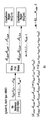
図2は、本発明の一実施例に係るインプットフォーマットブロックを示す。図2は、入力信号が単一入力ストリーム(single input stream)であるときのインプットフォーマットブロックを示す。 FIG. 2 shows an input format block according to an embodiment of the present invention. FIG. 2 shows an input format block when the input signal is a single input stream.
図2に図示されたインプットフォーマットブロックは、図1を参照して説明したインプットフォーマットブロック1000の一実施例に該当する。
The input format block shown in FIG. 2 corresponds to an embodiment of the
物理層(physical layer)への入力は、1つまたは多数のデータストリームからなることができる。それぞれのデータストリームは、1つのデータパイプによって伝達される。モードアダプテーション(mode adaptaion)モジュールは、入力されるデータストリームをBBF(baseband frame)のデータフィールドにスライスする。該当システムは、3種類の入力データストリーム、すなわちMPEG2-TS、IP、GS(generic stream)をサポートする。MPEG2-TSは、最初のバイトが同期バイト(0x47)の固定長(188バイト)のパケットを特徴とする。IPストリームは、IPパケットヘッダ内でシグナリングされる可変長IPデータグラムパケットから構成される。該当システムは、IPストリームに対してIPv4とIPv6の両方をサポートする。GSは、カプセル化パケットヘッダ内でシグナリングされる可変長パケットまたは一定の長さパケットから構成される。 The input to the physical layer can consist of one or multiple data streams. Each data stream is carried by one data pipe. The mode adaptation module slices an input data stream into BBF (baseband frame) data fields. The corresponding system supports three types of input data streams, namely MPEG2-TS, IP, and GS (generic stream). MPEG2-TS is characterized by a fixed-length (188 bytes) packet in which the first byte is a synchronization byte (0x47). The IP stream consists of variable length IP datagram packets signaled in the IP packet header. The corresponding system supports both IPv4 and IPv6 for the IP stream. The GS is composed of a variable length packet or a fixed length packet signaled in an encapsulated packet header.
(a)は信号データパイプに対するモードアダプテーション(mode adaptaion)ブロック2000及びストリームアダプテーション(stream adaptation)2010を示し、(b)はPLSデータを生成及び処理するためのPLS生成ブロック2020及びPLSスクランブラ2030を示す。各ブロックの動作について説明する。
(a) shows a
入力ストリームスプリッタは、入力されたTS、IP、GSストリームを多数のサービスまたはサービスコンポーネント(オーディオ、ビデオなど)ストリームに分割する。モードアダプテーション(mode adaptaion)モジュール2010は、CRCエンコーダ、BB(baseband)フレームスライサー、及びBBフレームヘッダ挿入ブロックから構成される。
The input stream splitter splits an input TS, IP, GS stream into a number of service or service component (audio, video, etc.) streams. The
CRCエンコーダは、ユーザパケット(user packet、UP)レベルでのエラー検出のための3種類のCRCエンコーディング、すなわちCRC-8、CRC-16、CRC-32を提供する。算出されたCRCバイトは、UPの後に添付される。CRC-8はTSストリームに使用され、CRC-32はIPストリームに使用される。GSストリームがCRCエンコーディングを提供しない場合、提案されたCRCエンコーディングが適用されなければならない。 The CRC encoder provides three types of CRC encoding, ie CRC-8, CRC-16, and CRC-32, for error detection at the user packet (UP) level. The calculated CRC byte is attached after UP. CRC-8 is used for the TS stream, and CRC-32 is used for the IP stream. If the GS stream does not provide CRC encoding, the proposed CRC encoding must be applied.
BBフレームスライサーは、入力を内部ロジカルビットフォーマットにマッピングする。最初の受信ビットはMSBと定義する。BBフレームスライサーは、使用可能データフィールド容量と同じ数の入力ビットを割り当てる。BBFペイロードと同じ数の入力ビットを割り当てるために、UPストリームがBBFのデータフィールドに適合するようにスライスされる。 The BB frame slicer maps the input to the internal logical bit format. The first received bit is defined as MSB. The BB frame slicer allocates the same number of input bits as the usable data field capacity. To allocate the same number of input bits as the BBF payload, the UP stream is sliced to fit into the BBF data field.
BBフレームヘッダ挿入ブロックは、2バイトの固定長BBFヘッダをBBフレームの前に挿入することができる。BBFヘッダは、STUFFI(1ビット)、SYNCD(13ビット)、及びRFU(2ビット)から構成される。固定された2バイトBBFヘッダだけでなく、BBFは2バイトBBFヘッダの終わりに拡張フィールド(1または3バイト)を有することができる。 The BB frame header insertion block can insert a 2-byte fixed-length BBF header before the BB frame. The BBF header is composed of STUFFI (1 bit), SYNCD (13 bits), and RFU (2 bits). In addition to the fixed 2-byte BBF header, the BBF can have an extension field (1 or 3 bytes) at the end of the 2-byte BBF header.
ストリームアダプテーション(stream adaptation)2010は、スタッフィング(stuffing)挿入ブロック及びBBスクランブラから構成される。
The
スタッフィング挿入ブロックは、スタッフィングフィールドをBBフレームのペイロードに挿入することができる。ストリームアダプテーション(stream adaptation)に対する入力データがBBフレームを満たすことに十分である場合、STUFFIは0に設定され、BBFはスタッフィングフィールドを有しない。そうでない場合、STUFFIは1に設定され、スタッフィングフィールドはBBFヘッダ直後に挿入される。スタッフィングフィールドは、2バイトのスタッフィングフィールドヘッダ及び可変サイズのスタッフィングデータを含む。 The stuffing insertion block can insert a stuffing field into the payload of the BB frame. If the input data for stream adaptation is sufficient to fill the BB frame, STUFFI is set to 0 and BBF has no stuffing field. Otherwise, STUFFI is set to 1 and the stuffing field is inserted immediately after the BBF header. The stuffing field includes a 2-byte stuffing field header and variable-size stuffing data.
BBスクランブラは、エネルギー分散のために完全なBBFをスクランブリングする。スクランブリングシーケンスはBBFと同期化される。スクランブリングシーケンスはフィードバックシフトレジスタによって生成される。 The BB scrambler scrambles the complete BBF for energy distribution. The scrambling sequence is synchronized with BBF. The scrambling sequence is generated by a feedback shift register.
PLS生成ブロック2020は、PLSデータを生成することができる。PLSは、受信機でフィジカルレイヤ(physical layer)データパイプに接続できる手段を提供する。PLSデータは、PLS1データ及びPLS2データから構成される。
The
PLS1データは、PLS2データのデコーディングに必要なパラメータだけでなく、システムに関する基本情報を伝達する固定されたサイズ、コーディング、変調を有するフレームでFSSに伝達されるPLSデータの最初の集合である。PLS1データは、PLS2データの受信及びデコーディングに要請されるパラメータを含む基本送信パラメータを提供する。また、PLS1データは、フレームグループのデュレーションの間一定である。 The PLS1 data is the first set of PLS data that is transmitted to the FSS in a frame having a fixed size, coding, and modulation that conveys basic information about the system as well as parameters required for decoding the PLS2 data. The PLS1 data provides basic transmission parameters including parameters required for receiving and decoding the PLS2 data. The PLS1 data is constant during the duration of the frame group.
PLS2データは、データパイプ及びシステムに関するより詳細なPLSデータを伝達するFSSに伝送されるPLSデータの二番目の集合である。PLS2は、受信機が所望するデータパイプのデコーディングに十分な情報を提供するパラメータを含む。PLS2シグナリングは、さらにPLS2スタティックデータ(PLS2-STATデータ)及びPLS2ダイナミックデータ(PLS2-DYNデータ)の二種類のパラメータから構成される。PLS2スタティックデータは、フレームグループのデュレーションの間スタティックのPLS2データであり、PLS2ダイナミックデータは、フレームごとにダイナミックに変化するPLS2データである。 PLS2 data is the second set of PLS data that is transmitted to the FSS that conveys more detailed PLS data about the data pipe and system. PLS2 includes parameters that provide sufficient information for the decoding of the data pipe desired by the receiver. PLS2 signaling is further composed of two types of parameters, PLS2 static data (PLS2-STAT data) and PLS2 dynamic data (PLS2-DYN data). PLS2 static data is static PLS2 data during the duration of a frame group, and PLS2 dynamic data is PLS2 data that dynamically changes from frame to frame.
PLSデータについての詳しい内容は後述する。 Details of the PLS data will be described later.
PLSスクランブラ2030は、エネルギー分散のために生成されたPLSデータをスクランブリングすることができる。
The
前述したブロックは、省略してもよく、類似または同一機能を有するブロックによって代替することもできる。 The blocks described above may be omitted, and may be replaced by blocks having similar or identical functions.
図3は、本発明の他の一実施例に係るインプットフォーマットブロックを示す。 FIG. 3 shows an input format block according to another embodiment of the present invention.
図3に図示されたインプットフォーマットブロックは、図1を参照して説明したインプットフォーマットブロック1000の一実施例に該当する。
The input format block shown in FIG. 3 corresponds to an embodiment of the
図3は、入力信号がマルチインプットストリーム(multi input stream)に該当する場合、インプットフォーマットブロックのモードアダプテーション(mode adaptaion)ブロックを示す。 FIG. 3 shows a mode adaptation block of an input format block when the input signal corresponds to a multi input stream.
マルチインプットストリーム(multi input stream)を処理するためのインプットフォーマットブロックのモードアダプテーション(mode adaptaion)ブロックは、マルチインプットストリームを独立的に処理することができる。 A mode adaptation block of an input format block for processing a multi input stream can process the multi-input stream independently.
図3に示すように、マルチインプットストリーム(multi input stream)をそれぞれ処理するためのモードアダプテーション(mode adaptaion)ブロックは、インプットストリームスプリッタ(input stream splitter)3000、インプットストリームシンクロナイザー(input stream synchronizer)3010、補償遅延(compensating delay)ブロック3020、ヌルパケット削除ブロック(null packet deletion block)3030、ヘッダ圧縮ブロック(header compression block)3040、CRCエンコーダ(CRC encoder)3050、BBフレームスライサー(BB frame slicer)3060、及びBBヘッダ挿入ブロック(BB header insertion block)3070を含むことができる。モードアダプテーション(mode adaptaion)ブロックの各ブロックについて説明する。
As shown in FIG. 3, a mode adaptation block for processing a multi input stream includes an
CRCエンコーダ3050、BBフレームスライサー3060、及びBBヘッダ挿入ブロック3070の動作は、図2を参照して説明したCRCエンコーダ、BBフレームスライサー、及びBBヘッダ挿入ブロックの動作に該当するので、その説明は省略する。
The operations of the CRC encoder 3050, the
インプットストリームスプリッタ3000は、入力されたTS、IP、GSストリームを多数のサービスまたはサービスコンポーネント(オーディオ、ビデオなど)ストリームに分割する。
The
インプットストリームシンクロナイザー3010はISSYと呼ぶことができる。ISSYは、いかなる入力データフォーマットに対してもCBR(constant bit rate)及び一定のEnd-to-End伝送遅延を保証する適合な手段を提供することができる。ISSYは、TSを伝達する多数のデータパイプの場合に常に利用され、GSストリームを伝達する多数のデータパイプに選択的に利用される。
補償遅延(compensating delay)ブロック3020は、受信機で追加メモリを必要とせず、TSパケット再結合メカニズムを許容するために、ISSY情報の挿入による分割されたTSパケットストリームを遅延させることができる。
Compensating
ヌルパケット削除ブロック3030は、TS入力ストリームの場合のみに使用される。いくつかのTS入力ストリームまたは分割されたTSストリームは、VBR(variable bit-rate)サービスをCBR TSストリームに収容するために存在する多数のヌルパケットを有することができる。この場合、不必要な伝送オーバーヘッドを避けるために、ヌルパケットは識別され伝送されないようにすることができる。受信機で、除去されたヌルパケットは、伝送に挿入されたDNP(deleted null-packet、削除されたヌルパケット)カウンターを参照して、本来存在していた正確な場所に再挿入することができ、CBRが保証されタイムスタンプ(PCR)を更新する必要がなくなる。
The null
ヘッダ圧縮ブロック3040は、TSまたはIP入力ストリームに対する伝送効率を増加させるために、パケットヘッダ圧縮を提供することができる。受信機は、ヘッダの特定部分に対するアプリオリ(a priori)情報を持つことがあるので、この既知の情報(known information)は送信機から削除することができる。
The
TSに対して、受信機は同期バイト構成(0x47)及びパケット長さ(188バイト)に関するアプリオリ情報を有することができる。入力されたTSが1つのPIDのみを有するコンテンツを伝達すれば、すなわち、1つのサービスコンポーネント(ビデオ、オーディオなど)またはサービスサブコンポーネント(SVCベースレイヤ、SVCエンハンスメントレイヤ、MVCベースビュー、またはMVC依存ビュー)に対してのみ、TSパケットヘッダ圧縮がTSに(選択的に)適用されるようにすることができる。TSパケットヘッダ圧縮は、入力ストリームがIPストリームである場合選択的に使用される。 For TS, the receiver can have a priori information on the sync byte configuration (0x47) and packet length (188 bytes). If the input TS carries content with only one PID, ie one service component (video, audio, etc.) or service subcomponent (SVC base layer, SVC enhancement layer, MVC base view, or MVC dependent view) Only) TS packet header compression can be (optionally) applied to the TS. TS packet header compression is selectively used when the input stream is an IP stream.
前記ブロックは、省略または類似または同一機能を有するブロックで代替することができる。 The block may be omitted or replaced with a block having similar or identical functions.
図4は、インプットシグナルが複数のインプットストリームに対応するとき、インプットフォーマットモジュールのストリーム適応ブロックを示す。 FIG. 4 shows a stream adaptation block of the input format module when the input signal corresponds to a plurality of input streams.
図4に示すインプットフォーマット設定ブロックは、図1を参照して説明したインプットフォーマットブロック1000の一実施形態に相当します。
The input format setting block shown in FIG. 4 corresponds to an embodiment of the
入力信号は、複数の入力ストリームに対応する場合、図4は、モジュールのフォーマットの入力ストリーム適応ブロックを示す図です。 If the input signal corresponds to multiple input streams, Figure 4 shows the input stream adaptation block in the module format.
図4に示すように、複数のインプットストリームをそれぞれ処理するためのモード適応ブロックは、スケジューラ4000、1フレーム遅延ブロック4010、スタッフィング挿入ブロック4020、インバンドシグナリング4030、BBフレームスクランブラ4040、PLS生成ブロック4050、及びPLSスクランブラ4060を含むことができる。説明はストリーム適応ブロックのそれぞれのブロックに対して提供される。
As shown in FIG. 4, the mode adaptation blocks for processing a plurality of input streams are a
スタッフィングデータブロック4020、BBフレームスクランブラ4040、PLS生成ブロック4050及びPLSスクランブラ4060は、図2に図示されたスタッフィング挿入ブロック、BBスクランブラ、PLS生成ブロック及びPLSスクランブラに対応する。従って、それに関する説明は省略する。
The stuffing
スケジューラ4000は、それぞれのDPのFECBLOCKの量から全体フレームにわたる全体的なセル割当を決定することができる。PLS、EAC及びFICのための割当を含んで、スケジューラは、フレームのFSS内PLSセルまたはインバンドシグナリングに伝送されるPLS2-DYNデータの値を生成する。FECBLOCK、EAC及びFICに関する詳しい説明は後述する。
The
1フレーム遅延ブロック4010は、DP内に挿入されるインバンドシグナリング情報のための現在のフレームを介して伝送される次のフレームに対するスケジューリング情報のような1つの伝送フレームによるインプットデータを遅延させることができる。
The one
インバンドシグナリング4030は、フレームのDP内PLS2データの遅延されない部分に挿入される。
In-
上述したブロックは、類似または同一機能を有するブロックによって省略または代替することができる。 The blocks described above can be omitted or replaced by blocks having similar or identical functions.
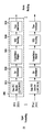
図5は、本発明の一実施例に係るBICMブロックを示す。 FIG. 5 shows a BICM block according to an embodiment of the present invention.
図5に図示されたBICMブロックは、図1を参照して説明したBICMブロック1010の一実施例に該当する。
The BICM block shown in FIG. 5 corresponds to an embodiment of the
上述したように、本発明の一実施例に係る次世代放送サービスに対する放送信号送信装置は、地上波放送サービス、モバイル放送サービス、UHDTVサービスなどを提供することができる。 As described above, the broadcast signal transmission apparatus for the next generation broadcast service according to an embodiment of the present invention can provide a terrestrial broadcast service, a mobile broadcast service, a UHDTV service, and the like.
QoSが本発明の一実施例に係る次世代放送サービスに対する放送信号送信装置によって提供されるサービスの特性に依存するので、それぞれのサービスに該当するデータはそれぞれ異なる方式を介して処理されなければならない。従って、本発明の一実施例に係るBICMブロックは、SISO、MISO、MIMO方式をそれぞれのデータ経路に該当するデータパイプに独立的に適用することで、各データパイプを独立的に処理することができる。結果的に、本発明の一実施例に係る次世代放送サービスに対する放送信号送信装置は、それぞれのデータパイプを介して伝送される各サービスまたはサービスコンポーネントに対するQoSを調節することができる。 Since QoS depends on the characteristics of the service provided by the broadcast signal transmitting apparatus for the next-generation broadcasting service according to an embodiment of the present invention, data corresponding to each service must be processed through different methods. . Therefore, the BICM block according to an embodiment of the present invention can process each data pipe independently by independently applying the SISO, MISO, and MIMO methods to the data pipe corresponding to each data path. it can. As a result, the broadcast signal transmitting apparatus for the next generation broadcasting service according to an embodiment of the present invention can adjust the QoS for each service or service component transmitted through each data pipe.
(a)はベースプロファイル及びハンドヘルドプロファイルによって共有されるBICMブロックを示し、(b)はアドバンスドプロファイルのBICMブロックを示す。 (a) shows the BICM block shared by the base profile and the handheld profile, and (b) shows the BICM block of the advanced profile.
ベースプロファイル及びハンドヘルドプロファイルによって共有されるBICMブロック及びアドバンスドプロファイルのBICMブロックは、それぞれのデータパイプを処理するための複数の処理ブロックを含むことができる。 The BICM block shared by the base profile and the handheld profile and the BICM block of the advanced profile can include a plurality of processing blocks for processing each data pipe.
ベースプロファイル及びハンドヘルドプロファイルに対するBICMブロック及びアドバンスドプロファイルに対するBICMブロックのそれぞれの処理ブロックについて説明する。 The processing blocks of the BICM block for the base profile and the handheld profile and the BICM block for the advanced profile will be described.
ベースプロファイル及びハンドヘルドプロファイルに対するBICMブロックの処理ブロック5000は、データFECエンコーダ5010、ビットインターリーバ5020、コンステレーションマッパ5030、SSD(signal space diversity)エンコーディングブロック5040、タイムインターリーバ5050を含むことができる。
The
データFECエンコーダ5010は、外部コーディング(BCH)及び内部コーディング(LDPC)を利用してFECBLOCK手順を生成するために、入力BBFにFECエンコーディングを実行する。外部コーディング(BCH)は、選択的なコーディング方法である。データFECエンコーダ5010の具体的な動作については後述する。
The
ビットインターリーバ5020は、効率的に実現可能な構造を提供しながらデータFECエンコーダ5010の出力をインターリービングして、LDPCコード及び変調方式の組合せで最適化された性能を達成することができる。ビットインターリーバ5020の具体的な動作については後述する。
The bit interleaver 5020 can interleave the output of the
コンステレーションマッパ5030は、QPSK、QAM-16、不均一QAM(NUQ-64、NUQ-256、NUQ-1024)または不均一コンステレーション(NUC-16、NUC-64、NUC-256、NUC-1024)を利用して、ベース及びハンドヘルドプロファイルにおいてビットインターリーバ5020からのそれぞれのセルワードを変調したり、アドバンスドプロファイルにおいてセルワードデマルチプレクサ5010-1からのセルワードを変調して、パワーが正規化されたコンステレーションポイントelを提供することができる。該当コンステレーションマッピングは、データパイプに対してのみ適用される。NUQが任意の形態を有する反面、QAM-16及びNUQは正四角形形状を有することが観察される。それぞれのコンステレーションが90度の倍数だけ回転すれば、回転したコンステレーションは本来のものと正確に重なる。回転対称特性によって実数及び虚数コンポーネントの容量及び平均パワーがお互いに等しくなる。NUQ及びNUCはいずれも各コードレート(code rate)に対して特別に定義され、使用される特定の1つは、PLS2データに保管されたパラメータDP_MODによってシグナリングされる。
The
タイムインターリーバ5050は、データパイプレベルで動作することができる。タイムインターリービングのパラメータは、それぞれのデータパイプに対して異なるように設定することができる。タイムインターリーバ5050の具体的な動作に関しては後述する。
The
アドバンスドプロファイルに対するBICMブロックの処理ブロック5000-1は、データFECエンコーダ、ビットインターリーバ、コンステレーションマッパ、及びタイムインターリーバを含むことができる。ただし、処理ブロック5000-1は、セルワードデマルチプレクサ5010-1及びMIMOエンコーディングブロック5020-1をさらに含むという点で、処理ブロック5000と区別される。
The processing block 5000-1 of the BICM block for the advanced profile may include a data FEC encoder, a bit interleaver, a constellation mapper, and a time interleaver. However, the processing block 5000-1 is distinguished from the
また、処理ブロック5000-1におけるデータFECエンコーダ、ビットインターリーバ、コンステレーションマッパ、タイムインターリーバの動作は、前述したデータFECエンコーダ5010、ビットインターリーバ5020、コンステレーションマッパ5030、タイムインターリーバ5050の動作に該当するので、その説明は省略する。
The operations of the data FEC encoder, bit interleaver, constellation mapper, and time interleaver in the processing block 5000-1 are the same as those of the
セルワードデマルチプレクサ5010-1は、アドバンスドプロファイルのデータパイプがMIMO処理のために単一セルワードストリームをデュアルセルワードストリームに分離するために使用される。セルワードデマルチプレクサ5010-1の具体的な動作に関しては後述する。 The cell word demultiplexer 5010-1 is used by an advanced profile data pipe to separate a single cell word stream into a dual cell word stream for MIMO processing. The specific operation of the cell word demultiplexer 5010-1 will be described later.
MIMOエンコーディングブロック5020-1は、MIMOエンコーディング方式を利用してセルワードデマルチプレクサ5010-1の出力を処理することができる。MIMOエンコーディング方式は、放送信号送信のために最適化されている。MIMO技術は、容量増加を得るための有望な方式であるが、チャネル特性に依存する。特に、放送に対して、異なる信号電波特性による2つのアンテナの間の受信信号パワーの差またはチャネルの強いLOSコンポーネントは、MIMOから容量利得を得難くする。提案されたMIMOエンコーディング方式は、MIMO出力信号のうちの1つの位相ランダム化及び回転に基づくプリコーディングを利用してこの問題を克服する。 The MIMO encoding block 5020-1 can process the output of the cell word demultiplexer 5010-1 using a MIMO encoding scheme. The MIMO encoding scheme is optimized for broadcast signal transmission. MIMO technology is a promising scheme for gaining capacity but depends on channel characteristics. In particular, for broadcasting, a difference in received signal power between two antennas due to different signal radio wave characteristics or a LOS component with a strong channel makes it difficult to obtain a capacity gain from MIMO. The proposed MIMO encoding scheme overcomes this problem using precoding based on phase randomization and rotation of one of the MIMO output signals.
MIMOエンコーディングは、送信機及び受信機の両方において少なくとも2つのアンテナを必要とする2x2MIMOシステムのために意図されている。2つのMIMOエンコーディングモードは、本提案であるFR-SM(full-rate spatial multiplexing)及びFRFD-SM(full-rate full-diversity spatial multiplexing)で定義される。FR-SMエンコーディングは、受信機側での比較的小さい複雑度増加で容量増加を提供する反面、FRFD-SMエンコーディングは、受信機側での大きい複雑度増加で容量増加及び追加的なダイバーシティー利得を提供する。提案されたMIMOエンコーディング方式は、アンテナ極性配置を制限しない。 MIMO encoding is intended for 2x2 MIMO systems that require at least two antennas at both the transmitter and receiver. Two MIMO encoding modes are defined by the proposed FR-SM (full-rate spatial multiplexing) and FRFD-SM (full-rate full-diversity spatial multiplexing). While FR-SM encoding provides increased capacity with a relatively small complexity increase at the receiver side, FRFD-SM encoding increases capacity and additional diversity gain with a large increase in complexity at the receiver side. I will provide a. The proposed MIMO encoding scheme does not limit the antenna polarity arrangement.
MIMO処理は、アドバンスドプロファイルフレームに要請されるが、これはアドバンスドプロファイルフレームにおけるすべてのデータパイプが、MIMOエンコーダによって処理されるということを意味する。MIMO処理は、データパイプレベルで適用される。コンステレーションマッパ出力ペア(pair)のNUQ(e1、i及びe2、i)は、MIMOエンコーダの入力に供給される。MIMOエンコーダ出力ペア(g1、i及びg2、i)は、それぞれの送信アンテナの同一キャリアk及びOFDMシンボルlによって伝送される。 MIMO processing is required for the advanced profile frame, which means that all data pipes in the advanced profile frame are processed by the MIMO encoder. MIMO processing is applied at the data pipe level. The NUQ (e1, i and e2, i) of the constellation mapper output pair is supplied to the input of the MIMO encoder. The MIMO encoder output pair (g1, i and g2, i) is transmitted by the same carrier k and OFDM symbol l of each transmit antenna.
前述したブロックは、省略または類似または同一機能を有するブロックで代替することができる。 The blocks described above can be omitted or replaced with blocks having similar or identical functions.
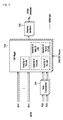
図6は、本発明の他の実施例に係るBICMブロックを示す。 FIG. 6 shows a BICM block according to another embodiment of the present invention.
図6に図示されたBICMブロックは、図1を参照して説明したBICMブロック1010の一実施例に該当する。
The BICM block shown in FIG. 6 corresponds to an embodiment of the
図6は、PLS、EAC、及びFICを保護するためのBICMブロックを示す。EACは、EAS情報データを伝達するフレームの一部であり、FICは、サービスと該当するベースデータパイプの間でマッピング情報を伝達するフレームにおけるロジカルチャネルである。EAC及びFICに対する詳細な説明は後述する。 FIG. 6 shows a BICM block for protecting PLS, EAC, and FIC. EAC is a part of a frame for transmitting EAS information data, and FIC is a logical channel in a frame for transmitting mapping information between a service and a corresponding base data pipe. Detailed descriptions of EAC and FIC will be described later.
図6に示すように、PLS、EAC、及びFICを保護するためのBICMブロックは、PLS FECエンコーダ6000、ビットインターリーバ6010、及びコンステレーションマッパ6020を含むことができる。
As shown in FIG. 6, a BICM block for protecting PLS, EAC, and FIC may include a PLS FEC encoder 6000, a bit interleaver 6010, and a
また、PLS FECエンコーダ6000は、スクランブラ、BCHエンコーディング/ゼロ挿入ブロック、LDPCエンコーディングブロック、及びLDPCパリティパンクチャリング(puncturing)ブロックを含むことができる。BICMブロックの各ブロックについて説明する。 In addition, the PLS FEC encoder 6000 may include a scrambler, a BCH encoding / zero insertion block, an LDPC encoding block, and an LDPC parity puncturing block. Each block of the BICM block will be described.
PLS FECエンコーダ6000は、スクランブリングされたPLS1/2データ、EAC及びFICセクションをエンコーディングすることができる。 The PLS FEC encoder 6000 can encode scrambled PLS1 / 2 data, EAC and FIC sections.
スクランブラは、BCHエンコーディング及びショートニング(shortening)及びパンクチャリングされたLDPCエンコーディング前にPLS1データ及びPLS2データをスクランブリングすることができる。 The scrambler can scramble PLS1 data and PLS2 data before BCH encoding and shortening and punctured LDPC encoding.
BCHエンコーディング/ゼロ挿入ブロックは、PLS保護のためのショートニングされたBCHコードを利用して、スクランブリングされたPLS1/2データに外部エンコーディングを行い、BCHエンコーディング後ゼロビットを挿入することができる。PLS1データに対してのみ、ゼロ挿入の出力ビットがLDPCエンコーディング前にパーミュテーション(permutation)される。 The BCH encoding / zero insertion block can perform external encoding on the scrambled PLS1 / 2 data using a shortened BCH code for PLS protection, and insert zero bits after BCH encoding. For PLS1 data only, the zero-inserted output bits are permutated before LDPC encoding.
LDPCエンコーディングブロックは、LDPCコードを利用してBCHエンコーディング/ゼロ挿入ブロックの出力をエンコーディングすることができる。完全なコーディングブロックを生成するために、Cldpc及びパリティビットPldpcはそれぞれのゼロが挿入されたPLS情報ブロックIldpcから組織的にエンコーディングされ、その後に添付される。 The LDPC encoding block can encode the output of the BCH encoding / zero insertion block using an LDPC code. In order to generate a complete coding block, Cldpc and parity bits Pldpc are systematically encoded from the PLS information block Ildpc with each zero inserted and then appended.
PLS1及びPLS2に対するLDPCコードパラメータは、次の表4のようである。 The LDPC code parameters for PLS1 and PLS2 are as shown in Table 4 below.
LDPCパリティパンクチャリングブロックは、PLS1データ及びPLS2データに対してパンクチャリングを行うことができる。 The LDPC parity puncturing block can perform puncturing on PLS1 data and PLS2 data.
ショートニングがPLS1データ保護に適用されると、一部LDPCパリティビットはLDPCエンコーディング後パンクチャリングされる。また、PLS2データ保護のために、PLS2のLDPCパリティビットがLDPCエンコーディング後パンクチャリングされる。これらパンクチャリングされたビットは伝送されない。 When shortening is applied to PLS1 data protection, some LDPC parity bits are punctured after LDPC encoding. In order to protect PLS2 data, the LDPC parity bits of PLS2 are punctured after LDPC encoding. These punctured bits are not transmitted.
ビットインターリーバ6010は、それぞれのショートニング及びパンクチャリングされたPLS1データ及びPLS2データをインターリービングすることができる。 The bit interleaver 6010 can interleave the respective shortened and punctured PLS1 data and PLS2 data.
コンステレーションマッパ6020は、ビットインターリービングされたPLS1データ及びPLS2データをコンステレーションにマッピングすることができる。
The
前述したブロックは、省略または類似または同一機能を有するブロックで代替することができる。 The blocks described above can be omitted or replaced with blocks having similar or identical functions.
図7は、本発明の一実施例に係るフレームビルディングブロック(frame building block)を示す。 FIG. 7 shows a frame building block according to an embodiment of the present invention.
図7に図示したフレームビルディングブロックは、図1を参照して説明したフレームビルディングブロック1020の一実施例に該当する。 The frame building block illustrated in FIG. 7 corresponds to an embodiment of the frame building block 1020 described with reference to FIG.
図7に示すように、フレームビルディングブロックは遅延補償ブロック7000、セルマッパ(cell mapper)7010、及び周波数インターリーバ(frequency interleaver)7020を含むことができる。フレームビルディングブロックの各ブロックに関して説明する。
As shown in FIG. 7, the frame building block may include a
遅延補償ブロック7000は、データパイプと該当するPLSデータの間のタイミングを調節して、送信機側でデータパイプと該当するPLSデータ間の同時性(co-time)を保証することができる。インプットフォーマットブロック及びBICMブロックによるデータパイプの遅延を対処することで、PLSデータはデータパイプだけ遅延される。BICMブロックの遅延は、主にタイムインターリーバ5050によるものである。インバンド(In-band)シグナリングデータは、次のタイムインターリービンググループの情報をシグナリングされるデータパイプより1フレーム前に伝達されるようにすることができる。遅延補償ブロックは、それに合わせてインバンド(In-band)シグナリングデータを遅延させる。
The
セルマッパ7010は、PLS、EAC、FIC、データパイプ、補助ストリーム、及びダミーセルをフレーム内でOFDMシンボルのアクティブ(active)キャリアにマッピングすることができる。セルマッパ7010の基本機能は、それぞれのデータパイプ、PLSセル、及びEAC/FICセルに対するタイムインターリービングによって生成されたデータセルを、存在すれば、1つのフレーム内でそれぞれのOFDMシンボルに該当するアクティブ(active)OFDMセルのアレイにマッピングするものである。(PSI(program specific information)/SIのような)サービスシグナリングデータは、個別的に収集されてデータパイプによって送信される。セルマッパは、フレーム構造の構成及びスケジューラーによって生成されたダイナミックインフォメーション(dynamic information)に応じて動作する。フレームに関する詳しい内容は後述する。 The cell mapper 7010 may map the PLS, EAC, FIC, data pipe, auxiliary stream, and dummy cell to the active carrier of the OFDM symbol in the frame. The basic function of the cell mapper 7010 is that data cells generated by time interleaving for each data pipe, PLS cell, and EAC / FIC cell, if present, are active corresponding to each OFDM symbol within one frame ( active) maps to an array of OFDM cells. Service signaling data (such as PSI (program specific information) / SI) is collected individually and transmitted over a data pipe. The cell mapper operates according to the structure of the frame structure and the dynamic information generated by the scheduler. Detailed contents regarding the frame will be described later.
周波数インターリーバ7020は、セルマッパ7010から受信されたデータセルをランダムにインターリービングして、周波数ダイバーシティーを提供することができる。また、周波数インターリーバ7020は、単一フレームで最大のインターリービング利得を得るために、他のインターリービングシード(seed)順を利用して、2つの順次的なOFDMシンボルから構成されたOFDMシンボルペア(pair)で動作することができる。
The
前述したブロックは、省略または類似または同一機能を有するブロックで代替することができる。 The blocks described above can be omitted or replaced with blocks having similar or identical functions.
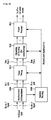
図8は、本発明の一実施例に係るOFDM生成ブロックを示す。 FIG. 8 shows an OFDM generation block according to an embodiment of the present invention.
図8に図示されたOFDM生成ブロックは、図1を参照して説明したOFDM生成ブロック1030の一実施例に該当する。
The OFDM generation block shown in FIG. 8 corresponds to an embodiment of the
OFDM生成ブロックは、フレームビルディングブロックによって生成されたセルによってOFDMキャリアを変調して、パイロットを挿入し、伝送のための時間領域信号を生成する。また、該当ブロックは順次ガードインターバルを挿入し、PAPR減少処理を適用して最終RF信号を生成する。 The OFDM generation block modulates an OFDM carrier with cells generated by the frame building block, inserts pilots, and generates a time domain signal for transmission. In addition, the corresponding block sequentially inserts a guard interval and applies a PAPR reduction process to generate a final RF signal.
図8に示すように、OFDM生成ブロックは、パイロット及びリザーブドトーン挿入ブロック(pilot and reserved tone insertion block)8000、2D-eSFN(single frequency network)エンコーディングブロック8010、IFFT(inverse fast Fourier transform)ブロック8020、PAPR減少ブロック8030、ガードインターバル挿入ブロック(guard interval insertion block)8040、プリアンブル挿入ブロック(preamble insertion block)8050、その他システム挿入ブロック8060、及びDACブロック8070を含むことができる。
As shown in FIG. 8, the OFDM generation block includes a pilot and reserved
パイロットと予約トーン挿入ブロック8000は、パイロットや予約済みのトーンを挿入することができます。
Pilot and reserved
OFDMシンボル内の種々のセルが送信値が受信機において事前に知られているパイロットとして既知の基準情報で変調されます。パイロット・セルの情報は、分散パイロット、継続的なパイロット、エッジパイロット、FSS(フレームシグナリングシンボル)のパイロットとPES(フレームエッジシンボル)のパイロットから構成されています。各パイロットは、パイロットタイプとパイロットパターンに応じて特定の昇圧電力レベルで送信されます。パイロット情報の値は、値の系列、任意の所与のシンボルを各送信キャリアのための1つである参照配列に由来します。パイロットは、フレーム同期、周波数同期、時間同期、チャネル推定、および送信モードの識別に使用することができ、また、位相雑音を追跡するために使用することができます。 Various cells within the OFDM symbol are modulated with reference information known as pilots whose transmit values are known in advance at the receiver. Pilot cell information consists of distributed pilot, continuous pilot, edge pilot, FSS (frame signaling symbol) pilot and PES (frame edge symbol) pilot. Each pilot is transmitted at a specific boost power level depending on the pilot type and pilot pattern. The value of the pilot information comes from a sequence of values, a reference array that is one given for each transmitted carrier, any given symbol. The pilot can be used for frame synchronization, frequency synchronization, time synchronization, channel estimation, and transmission mode identification, and can be used to track phase noise.
参照配列から取られた参照情報は、フレームのプリアンブル、PSS及びPESを除くすべてのシンボルに散乱パイロット・セルで送信されます。継続的なパイロットは、フレームのすべてのシンボルに挿入されます。継続的なパイロットの数及び位置は、PPTの大きさと散乱パイロットパターンの両方に依存します。エッジキャリアは、プリアンブルシンボルを除くすべてのシンボルのエッジパイロットです。これらは、スペクトルの端までの周波数補間を可能にするために挿入されています。PSSパイロットはPSS(複数可)に挿入され、PESパイロットは、PESに挿入されています。これらは、フレームのエッジまでの時間補間を可能にするために挿入されています。 The reference information taken from the reference sequence is transmitted in the scattered pilot cells to all symbols except the frame preamble, PSS and PES. Continuous pilots are inserted at every symbol of the frame. The number and location of continuous pilots depends on both the PPT size and the scattered pilot pattern. The edge carrier is the edge pilot for all symbols except the preamble symbol. They are inserted to allow frequency interpolation to the end of the spectrum. The PSS pilot is inserted into the PSS (s) and the PES pilot is inserted into the PES. These are inserted to allow time interpolation to the edge of the frame.
本発明の実施形態に係るシステムは、分散MISO方式が、必要に応じて、非常に強固な伝送モードをサポートするために使用されるSPNのネットワークをサポートします。2D-ESPNは、SPNネットワーク内の異なる送信機サイトに位置して、それぞれが複数の送信アンテナを使用する分散MISO方式です。 The system according to an embodiment of the present invention supports a network of SPNs where the distributed MISO method is used to support a very robust transmission mode if necessary. 2D-ESPN is a distributed MISO method that is located at different transmitter sites in the SPN network, each using multiple transmit antennas.
2D-ESPNの符号化ブロック8010は、SPNの設定時間と周波数ダイバーシティーの両方を作成するために、複数の送信機から送信された信号の位相を歪めるために2D-ESPN処理を処理することができます。したがって、低いフラットフェージングや長い時間のために、深いフェージングバーストエラーを軽減することができます。 The 2D-ESPN encoding block 8010 may process 2D-ESPN processing to distort the phase of signals transmitted from multiple transmitters in order to create both SPN setup time and frequency diversity. I can do it. Therefore, deep fading burst errors can be reduced due to low flat fading and long time.
IPPTブロック8020は、OPDM変調方式を用いた2D-ESPNの符号化ブロック8010の出力を調節することができます。パイロット(または予約トーンなど)として指定されていないデータシンボルの任意のセルは、周波数インターリーバからのデータセルの1つを運びます。セルは、OPDMキャリアにマップされます。
PAPR低減ブロック8030は、時間領域内の様々なPAPR低減アルゴリズムを使用して入力信号のPAPR低減を行うことができます。 The PAPR reduction block 8030 can perform PAPR reduction of input signals using various PAPR reduction algorithms in the time domain.
ガードインターバル挿入ブロック8040は、ガードインターバルを挿入することができますし、プリアンブル挿入ブロック8050は、信号の前にプリアンブルを挿入することができます。プリアンブルの構造の詳細については後述します。他のシステムの挿入ブロック8060は、放送サービスを提供する二つ以上の異なるブロードキャスト送信/受信システムのデータが同時に同じRP信号帯域幅で送信することができ、時間領域におけるブロードキャスト送信/受信システムの複数の信号を多重化することができます。この場合、2つ以上の異なるブロードキャスト送信/受信システムは、異なるブロードキャストサービスを提供するシステムを指します。異なるブロードキャストサービスは、それぞれの放送サービスに関連するデータは、異なるフレームを介して送信することができる等の地上波放送サービス、モバイル放送サービスを意味することができます。
The guard
DACブロック8070は、アナログ信号と出力アナログ信号に入力されたデジタル信号に変換することができます。DACブロック7800から出力された信号は、物理層プロファイルに応じて複数の出力アンテナを介して送信されることができます。本発明の実施形態に係る送信アンテナは、垂直または水平の極性を有することができます。
The
上記ブロックは省略する、又は設計に応じて、類似または同一の機能を有するブロックに置き換えることができます。 The above blocks can be omitted or replaced with blocks with similar or identical functions depending on the design.
図9は、本発明の一実施例に係る次世代放送サービスに対する放送信号受信装置の構造を示す。 FIG. 9 shows a structure of a broadcast signal receiving apparatus for the next generation broadcasting service according to an embodiment of the present invention.
本発明の一実施例に係る次世代放送サービスに対する放送信号受信装置は、図1を参照して説明した次世代放送サービスに対する放送信号送信装置に対応する。 The broadcast signal receiver for the next-generation broadcast service according to an embodiment of the present invention corresponds to the broadcast signal transmitter for the next-generation broadcast service described with reference to FIG.
本発明の一実施例に係る次世代放送サービスに対する放送信号受信装置は、同期及び復調モジュール(synchronization & demodulation module)9000、フレーム解析モジュール(frame parsing module)9010、デマッピング及びデコーディングモジュール(demapping & decoding module)9020、出力プロセッサ(output processor)9030、及びシグナリングデコーディングモジュール(signaling decoding module)9040を含むことができる。放送信号受信装置の各モジュールの動作について説明する。
A broadcasting signal receiver for a next generation broadcasting service according to an embodiment of the present invention includes a synchronization and
同期及び復調モジュール9000は、m個の受信アンテナを介して入力信号を受信し、放送信号受信装置に該当するシステムに対して信号検出及び同期化を実行し、放送信号送信装置によって実行される手順の逆過程に該当する復調を実行することができる。
The synchronization and
フレーム解析モジュール9100は、入力信号フレームを解析し、ユーザによって選択されたサービスが伝送されるデータを抽出することができる。放送信号送信装置がインターリービングを実行すると、フレーム解析モジュール9100は、インターリービングの逆過程に該当するデインターリービングを実行することができる。この場合、抽出されるべき信号及びデータの位置が、シグナリングデコーディングモジュール9400から出力されたデータをデコーディングすることで取得され、放送信号送信装置によって生成されたスケジューリング情報が復元される。 The frame analysis module 9100 can analyze an input signal frame and extract data on which a service selected by a user is transmitted. When the broadcast signal transmitting apparatus performs interleaving, the frame analysis module 9100 can perform deinterleaving corresponding to the reverse process of interleaving. In this case, the position of the signal and data to be extracted is obtained by decoding the data output from the signaling decoding module 9400, and the scheduling information generated by the broadcast signal transmitting apparatus is restored.
デマッピング及びデコーディングモジュール9200は、入力信号をビット領域データに変換した後、必要に応じてビット領域データをデインターリービングすることができる。デマッピング及びデコーディングモジュール9200は、伝送効率のために適用されたマッピングに対するデマッピングを実行し、デコーディングを介して伝送チャネルで発生したエラーを訂正することができる。この場合、デマッピング及びデコーディングモジュール9200は、シグナリングデコーディングモジュール9400から出力されたデータをデコーディングすることで、デマッピング及びデコーディングのために必要な伝送パラメータを取得することができる。 The demapping and decoding module 9200 may deinterleave the bit area data as necessary after converting the input signal into the bit area data. The demapping and decoding module 9200 may perform demapping on the mapping applied for transmission efficiency and correct errors generated in the transmission channel via decoding. In this case, the demapping and decoding module 9200 can acquire transmission parameters necessary for demapping and decoding by decoding data output from the signaling decoding module 9400.
出力プロセッサ9300は、伝送効率を向上させるために、放送信号送信装置によって適用される多様な圧縮/信号処理手順の逆過程を実行することができる。この場合、出力プロセッサ9300は、シグナリングデコーディングモジュール9400から出力されたデータから必要な制御情報を取得することができる。出力プロセッサ8300の出力は、放送信号送信装置に入力される信号に該当し、例えばMPEG-TS、IPストリーム(v4またはv6)及びGSである。 The output processor 9300 may perform reverse processes of various compression / signal processing procedures applied by the broadcast signal transmission apparatus in order to improve transmission efficiency. In this case, the output processor 9300 can obtain necessary control information from the data output from the signaling decoding module 9400. The output of the output processor 8300 corresponds to a signal input to the broadcast signal transmission apparatus, and is, for example, MPEG-TS, IP stream (v4 or v6), and GS.
シグナリングデコーディングモジュール9400は、同期及び復調モジュール9000によって復調された信号からPLS情報を取得することができる。上述したように、フレーム解析モジュール9100、デマッピング及びデコーディングモジュール9200、出力プロセッサ9300は、シグナリングデコーディングモジュール9400から出力されたデータを利用してその機能を実行することができる。
The signaling decoding module 9400 may obtain PLS information from the signal demodulated by the synchronization and
図10は、本発明の一実施例に係るフレーム構造を示す。 FIG. 10 shows a frame structure according to an embodiment of the present invention.
図10は、フレームタイプの構成例及びスーパーフレームにおけるFRU(frame repetition unit、フレーム繰返し単位)を示す。(a)は、本発明の一実施例に係るスーパーフレームを示し、(b)は、本発明の一実施例に係るFRUを示し、(c)はFRUでの多様なフィジカルプロファイル(PHY profile)のフレームを示し、(d)はフレームの構造を示す。 FIG. 10 shows a configuration example of a frame type and FRU (frame repetition unit) in a super frame. (a) shows a superframe according to an embodiment of the present invention, (b) shows an FRU according to an embodiment of the present invention, (c) shows various physical profiles (PHY profiles) in the FRU. (D) shows the structure of the frame.
スーパーフレームは、8個のFRUで構成することができる。FRUはフレームのTDMに対する基本マルチプレックス単位であり、スーパーフレームで8回繰り返される。 A superframe can consist of 8 FRUs. The FRU is a basic multiplex unit for the TDM of a frame and is repeated 8 times in a superframe.
FRUで各フレームは、フィジカルプロファイル(ベース、ハンドヘルド、アドバンスドプロファイル)のうちの1つまたはFEFに属する。FRUでフレームの最大許容数は4であり、与えられたフィジカルプロファイルは、FRUで0回〜4回のいずれかの回数だけ出現できる(例えば、ベース、ベース、ハンドヘルド、アドバンスド)。フィジカルプロファイルの定義は、必要に応じてプリアンブルにおけるPHY_PROFILEのリザーブド値(reserved value)を利用して拡張可能である。 In the FRU, each frame belongs to one of the physical profiles (base, handheld, advanced profile) or FEF. The maximum allowable number of frames in FRU is 4, and a given physical profile can appear anywhere from 0 to 4 times in FRU (eg, base, base, handheld, advanced). The definition of the physical profile can be extended using the reserved value (reserved value) of PHY_PROFILE in the preamble as necessary.
FEF部分は、含まれる場合FRUの終わりに挿入される。FEFがFRUに含まれる場合、FEFの最大数はスーパーフレームで8である。FEF部分がお互いに隣接することは推奨されない。 The FEF part is inserted at the end of the FRU if included. When FEF is included in FRU, the maximum number of FEF is 8 in superframe. It is not recommended that the FEF parts be adjacent to each other.
1つのフレームは、多数のOFDMシンボル及びプリアンブルにさらに分離される。(d)に示したように、フレームは、プリアンブル、1つ以上のFSS、ノーマルデータシンボル、FESを含む。 One frame is further separated into a number of OFDM symbols and preambles. As shown in (d), the frame includes a preamble, one or more FSSs, normal data symbols, and FES.
プリアンブルは、高速フューチャーキャストUTBシステム信号検出を可能にし、信号の効率的な送信及び受信のための基本伝送パラメータの集合を提供する特別なシンボルである。プリアンブルについての詳しい内容は後述する。 The preamble is a special symbol that enables fast future cast UTB system signal detection and provides a set of basic transmission parameters for efficient transmission and reception of signals. Detailed contents of the preamble will be described later.
FSSの主な目的は、PLSデータを伝達することである。高速同期化及びチャネル推定のために、これに伴うPLSデータの高速デコーディングのために、FSSはノーマルデータシンボルより高密度なパイロットパターンを有する。FESはFSSと完全に同一なパイロットを有するが、これはFESの直前のシンボルに対して外挿(extrapolation)なしにFES内での周波数のみの補間(interpolation)及び時間的補間(temporal interpolation)を可能とする。 The main purpose of FSS is to communicate PLS data. For fast synchronization and channel estimation, the FSS has a higher density pilot pattern than normal data symbols due to the accompanying fast decoding of PLS data. FES has exactly the same pilot as FSS, but this performs frequency-only interpolation and temporal interpolation within FES without extrapolation on the symbol immediately preceding FES. Make it possible.
図11は、本発明の一実施例に係るフレームのシグナリング階層構造(signaling hierarchy structure)を示す。 FIG. 11 illustrates a signaling hierarchy structure of a frame according to an embodiment of the present invention.
図11は、シグナリング階層構造を示すが、これは3つの主な部分であるプリアンブルシグナリングデータ11000、PLS1データ11010、及びPLS2データ11020に分割される。各フレームごとにプリアンブル信号によって伝達されるプリアンブルの目的は、フレームの基本伝送パラメータ及び伝送タイプを示すことである。PLS1は、受信機が関心のあるデータパイプに接続するためのパラメータを含むPLS2データに接続してデコーディングすることができるようにする。PLS2は、各フレームごとに伝達され、2つの主な部分であるPLS2-STATデータとPLS2-DYNデータに分割される。PLS2データのスタティック及びダイナミック部分には、必要に応じてパディングがなされる。
FIG. 11 shows a signaling hierarchy, which is divided into three main parts:
図12は、本発明の一実施例に係るプリアンブルシグナリングデータを示す。 FIG. 12 shows preamble signaling data according to an embodiment of the present invention.
プリアンブルシグナリングデータは、受信機がフレーム構造内でPLSデータに接続し、データパイプを追跡できるようにするために必要な21ビットの情報を伝達する。プリアンブルシグナリングデータについての詳しい内容は、次のようである。 Preamble signaling data carries 21 bits of information necessary for the receiver to connect to the PLS data in the frame structure and track the data pipe. Detailed contents of the preamble signaling data are as follows.
PHY_PROFILE:該当3ビットフィールドは、現在のフレームのフィジカルプロファイルタイプを示す。異なるフィジカルプロファイルタイプのマッピングは、以下の表5に示す。 PHY_PROFILE: The corresponding 3-bit field indicates the physical profile type of the current frame. The mapping of the different physical profile types is shown in Table 5 below.
FFT_SIZE:該当2ビットフィールドは、以下の表6で説明するように、フレームグループ内で現在のフレームのFFTサイズを示す。 FFT_SIZE: The corresponding 2-bit field indicates the FFT size of the current frame in the frame group, as described in Table 6 below.
GI_FRACTION:該当3ビットフィールドは、以下の表7で説明するように、現在のスーパーフレームにおけるガードインターバルの一部(fraction)値を示す。 GI_FRACTION: The corresponding 3-bit field indicates a fraction value of the guard interval in the current superframe as described in Table 7 below.
EAC_FLAG:該当1ビットフィールドは、EACが現在のフレームに提供されるのか否かを示す。該当フィールドが1に設定されると、EASが現在のフレームに提供される。該当フィールドが0に設定されると、EASが現在のフレームに伝達されない。該当フィールドは、スーパーフレーム内でダイナミックに転換される。 EAC_FLAG: The corresponding 1-bit field indicates whether an EAC is provided in the current frame. If the field is set to 1, EAS is provided for the current frame. If the corresponding field is set to 0, EAS is not transmitted to the current frame. The corresponding field is dynamically changed within the superframe.
PILOT_MODE:該当1ビットフィールドは、現在のフレームグループで現在のフレームに対してパイロットモードがモバイルモードであるのかまたは固定モードであるのかを示す。該当フィールドが0に設定されると、モバイルパイロットモードが使用される。該当フィールドが1に設定されると、固定パイロットモードが使用される。 PILOT_MODE: The corresponding 1-bit field indicates whether the pilot mode is the mobile mode or the fixed mode for the current frame in the current frame group. When the corresponding field is set to 0, the mobile pilot mode is used. If the corresponding field is set to 1, the fixed pilot mode is used.
PAPR_FLAG:該当1ビットフィールドは、現在のフレームグループで現在のフレームに対してPAPR減少が使用されているのか否かを示す。該当フィールドが1に設定されると、トーン予約(tone reservation)がPAPR減少のために使用される。該当フィールドが0に設定されると、PAPR減少が使用されない。 PAPR_FLAG: The corresponding 1-bit field indicates whether or not PAPR reduction is used for the current frame in the current frame group. If the corresponding field is set to 1, tone reservation is used for PAPR reduction. If the field is set to 0, PAPR reduction is not used.
FRU_CONFIGURE:該当3ビットフィールドは、現在のスーパーフレームで存在するFRUのフィジカルプロファイルタイプ構成を示す。現在のスーパーフレームですべてのプリアンブルにおける該当フィールドで、現在のスーパーフレームで伝達されるすべてのプロファイルタイプが識別される。該当3ビットフィールドは、以下の表8に示したように、それぞれのプロファイルに対して異なるように定義される。 FRU_CONFIGURE: The corresponding 3-bit field indicates the physical profile type configuration of the FRU existing in the current superframe. In the corresponding field in all preambles in the current superframe, all profile types carried in the current superframe are identified. The corresponding 3-bit field is defined differently for each profile as shown in Table 8 below.
RESERVED:該当7ビットフィールドは、将来使用のためにリザーブされる(reserved)。 RESERVED: The corresponding 7-bit field is reserved for future use.
図13は、本発明の一実施例に係るPLS1データを示す。 FIG. 13 shows PLS1 data according to an embodiment of the present invention.
PLS1データは、PLS2の受信及びデコーディングを可能とするために必要なパラメータを含んだ基本伝送パラメータを提供する。上述したように、PLS1データは、1つのフレームグループの全体デュレーションの間変化しない。PLS1データのシグナリングフィールドの具体的な定義は次のようである。 PLS1 data provides basic transmission parameters including parameters necessary to enable PLS2 reception and decoding. As described above, PLS1 data does not change during the entire duration of one frame group. The specific definition of the signaling field of PLS1 data is as follows.
PREAMBLE_DATA:該当20ビットフィールドは、EAC_FLAGを除いたプリアンブルシグナリングデータのコピーである。 PREAMBLE_DATA: The corresponding 20-bit field is a copy of preamble signaling data excluding EAC_FLAG.
NUM_FRAME_FRU:該当2ビットフィールドは、FRU当たりのフレーム数を示す。 NUM_FRAME_FRU: The corresponding 2-bit field indicates the number of frames per FRU.
PAYLOAD_TYPE:該当3ビットフィールドは、フレームグループで伝達されるペイロードデータのフォーマットを示す。PAYLOAD_TYPEは、表9に示したようにシグナリングされる。 PAYLOAD_TYPE: The corresponding 3-bit field indicates the format of payload data transmitted in the frame group. PAYLOAD_TYPE is signaled as shown in Table 9.
NUM_FSS:該当2ビットフィールドは、現在のフレームでFSSの数を示す。 NUM_FSS: The corresponding 2-bit field indicates the number of FSSs in the current frame.
SYSTEM_VERSION:該当8ビットフィールドは、伝送される信号フォーマットのバージョンを示す。SYSTEM_VERSIONは主バージョン及び副バージョンの2つの4ビットフィールドに分離される。 SYSTEM_VERSION: The corresponding 8-bit field indicates the version of the signal format to be transmitted. SYSTEM_VERSION is separated into two 4-bit fields: main version and subversion.
主バージョン:SYSTEM_VERSIONフィールドのMSBである4ビットは、主バージョン情報を示す。主バージョンフィールドにおける変化は互換が不可能な変化を示す。デフォルト値は0000である。この標準に記述されたバージョンに対して、値が0000に設定される。 Main version: 4 bits that are MSBs of the SYSTEM_VERSION field indicate main version information. Changes in the main version field indicate changes that are not compatible. The default value is 0000. The value is set to 0000 for the version described in this standard.
副バージョン:SYSTEM_VERSIONフィールドのLSBである4ビットは、副バージョン情報を示す。副バージョンフィールドにおける変化は互換が可能である。 Subversion: 4 bits which are LSBs of the SYSTEM_VERSION field indicate subversion information. Changes in the subversion field are interchangeable.
CELL_ID:これは、ATSCネットワークで地理的セルを一意に識別する16ビットフィールドである。ATSCセルカバレッジは、フューチャーキャストUTBシステム当たりに使用される周波数の数に応じて1つ以上の周波数から構成される。CELL_IDの値が知られていないか特定されないと、該当フィールドは0に設定される。 CELL_ID: This is a 16-bit field that uniquely identifies a geographic cell in an ATSC network. ATSC cell coverage is composed of one or more frequencies depending on the number of frequencies used per Futurecast UTB system. If the value of CELL_ID is not known or not specified, the corresponding field is set to 0.
NETWORK_ID:これは現在のATSCネットワークを一意に識別する16ビットフィールドである。 NETWORK_ID: This is a 16-bit field that uniquely identifies the current ATSC network.
SYSTEM_ID:該当16ビットフィールドは、ATSCネットワーク内でフューチャーキャストUTBシステムを一意に識別する。フューチャーキャストUTBシステムは、入力が1つ以上の入力ストリーム(TS、IP、GS)であり、出力がRF信号である地上波放送システムである。フューチャーキャストUTBシステムは、存在する場合FEF及び1つ以上のフィジカルプロファイルを伝達する。同一フューチャーキャストUTBシステムは、異なる入力ストリームを伝達し、異なる地理的領域で異なるRFを使用でき、ローカルサービス挿入を許容する。フレーム構造及びスケジューリングは1つの場所で制御され、フューチャーキャストUTBシステム内ですべての伝送に対して同一である。1つ以上のフューチャーキャストUTBシステムは、すべて同一フィジカル構造及び構成を有する同一SYSTEM_IDの意味を持つことができる。 SYSTEM_ID: The corresponding 16-bit field uniquely identifies the Futurecast UTB system within the ATSC network. The Futurecast UTB system is a terrestrial broadcasting system in which an input is one or more input streams (TS, IP, GS) and an output is an RF signal. The Futurecast UTB system conveys the FEF and one or more physical profiles when present. The same Futurecast UTB system can carry different input streams, use different RFs in different geographic regions, and allow local service insertion. The frame structure and scheduling are controlled in one place and are the same for all transmissions in the Futurecast UTB system. One or more future cast UTB systems can all have the same SYSTEM_ID meaning with the same physical structure and configuration.
次のループ(loop)は、各フレームタイプの長さ及びFRU構成を示すFRU_PHY_PROFILE、FRU_FRAME_LENGTH、FRU_GI_FRACTION、RESERVEDから構成される。ループ(loop)のサイズは、FRU内で4つのフィジカルプロファイル(FEF含む)がシグナリングされるように固定される。NUM_FRAME_FRUが4より小さいと、使用されないフィールドはゼロで満たされる。 The next loop is composed of FRU_PHY_PROFILE, FRU_FRAME_LENGTH, FRU_GI_FRACTION, and RESERVED indicating the length and FRU configuration of each frame type. The size of the loop is fixed so that four physical profiles (including FEF) are signaled in the FRU. If NUM_FRAME_FRU is less than 4, unused fields are filled with zeros.
FRU_PHY_PROFILE:該当3ビットフィールドは、関連したFRUの(i+1)番目のフレーム(iはループ(loop)インデックス)のフィジカルプロファイルタイプを示す。該当フィールドは、表8に示したものと同一シグナリングフォーマットを用いる。 FRU_PHY_PROFILE: The corresponding 3-bit field indicates the physical profile type of the (i + 1) -th frame (i is a loop index) of the related FRU. The corresponding field uses the same signaling format as shown in Table 8.
FRU_FRAME_LENGTH:該当2ビットフィールドは、関連したFRUの(i+1)番目のフレームの長さを示す。FRU_GI_FRACTIONと一緒にFRU_FRAME_LENGTHを使用すると、フレームデュレーションの正確な値が得られる。 FRU_FRAME_LENGTH: The corresponding 2-bit field indicates the length of the (i + 1) th frame of the related FRU. Use FRU_FRAME_LENGTH with FRU_GI_FRACTION to get the exact frame duration value.
FRU_GI_FRACTION:該当3ビットフィールドは、関連したFRUの(i+1)番目のフレームのガードインターバルの一部値を示す。FRU_GI_FRACTIONは、表7に従ってシグナリングされる。 FRU_GI_FRACTION: The corresponding 3-bit field indicates a partial value of the guard interval of the (i + 1) th frame of the related FRU. FRU_GI_FRACTION is signaled according to Table 7.
RESERVED:該当4ビットフィールドは、将来使用のためにリザーブされる(reserved)。 RESERVED: The corresponding 4-bit field is reserved for future use.
次のフィールドは、PLS2データをデコーディングするためのパラメータを提供する。 The next field provides parameters for decoding the PLS2 data.
PLS2_FEC_TYPE:該当2ビットフィールドは、PLS2保護によって使用されるFECタイプを示す。FECタイプは、表10に従ってシグナリングされる。LDPCコードについての詳しい内容は後述する。 PLS2_FEC_TYPE: The corresponding 2-bit field indicates the FEC type used by PLS2 protection. The FEC type is signaled according to Table 10. Details of the LDPC code will be described later.
PLS2_MOD:該当3ビットフィールドは、PLS2によって使用される変調タイプを示す。変調タイプは、表11に従ってシグナリングされる。 PLS2_MOD: The corresponding 3-bit field indicates a modulation type used by PLS2. The modulation type is signaled according to Table 11.
PLS2_SIZE_CELL:該当15ビットフィールドは、現在のフレームグループで伝達されるPLS2に対するすべてのコーディングブロックのサイズ(QAMセルの数として特定される)のCtotal_partial_blockを示す。該当値は、現在のフレームグループの全体デュレーションの間一定である。 PLS2_SIZE_CELL: The corresponding 15-bit field indicates Ctotal_partial_block of the size of all coding blocks (specified as the number of QAM cells) for PLS2 transmitted in the current frame group. The value is constant during the entire duration of the current frame group.
PLS2_STAT_SIZE_BIT:該当14ビットフィールドは、現在のフレームグループに対するPLS2-STATのサイズをビット数で示す。該当値は、現在のフレームグループの全体デュレーションの間一定である。 PLS2_STAT_SIZE_BIT: The corresponding 14-bit field indicates the size of PLS2-STAT for the current frame group in the number of bits. The value is constant during the entire duration of the current frame group.
PLS2_DYN_SIZE_BIT:該当14ビットフィールドは、現在のフレームグループに対するPLS2-DYNのサイズをビット数で示す。該当値は、現在のフレームグループの全体デュレーションの間一定である。 PLS2_DYN_SIZE_BIT: The corresponding 14-bit field indicates the size of PLS2-DYN for the current frame group in the number of bits. The value is constant during the entire duration of the current frame group.
PLS2_REP_FLAG:該当1ビットフラッグは、PLS2繰返しモードが現在のフレームグループで使用されているのか否かを示す。該当フィールドの値が1に設定されると、PLS2繰返しモードは活性化される。該当フィールドの値が0に設定されると、PLS2繰返しモードは非活性化される。 PLS2_REP_FLAG: The corresponding 1-bit flag indicates whether the PLS2 repeat mode is used in the current frame group. When the value of the corresponding field is set to 1, the PLS2 repeat mode is activated. When the value of the corresponding field is set to 0, the PLS2 repeat mode is deactivated.
PLS2_REP_SIZE_CELL:該当15ビットフィールドは、PLS2繰返しが使用される場合、現在のフレームグループの各フレームごとに伝達されるPLS2に対する部分コーディングブロックのサイズ(QAMセルの数として特定される)のCtotal_partial_blockを示す。繰返しが使用されない場合、該当フィールドの値は0と同一である。該当値は、現在のフレームグループの全体デュレーションの間一定である。 PLS2_REP_SIZE_CELL: The corresponding 15-bit field indicates Ctotal_partial_block of the size of the partial coding block (specified as the number of QAM cells) for PLS2 transmitted for each frame of the current frame group when PLS2 repetition is used. If repetition is not used, the value of the corresponding field is equal to 0. The value is constant during the entire duration of the current frame group.
PLS2_NEXT_FEC_TYPE:該当2ビットフィールドは、次のフレームグループの各フレームで伝達されるPLS2に使用されるFECタイプを示す。FECタイプは、表10に従ってシグナリングされる。 PLS2_NEXT_FEC_TYPE: The corresponding 2-bit field indicates the FEC type used for PLS2 transmitted in each frame of the next frame group. The FEC type is signaled according to Table 10.
PLS2_NEXT_MOD:該当3ビットフィールドは、次のフレームグループの各フレームで伝達されるPLS2に使用される変調タイプを示す。変調タイプは、表11に従ってシグナリングされる。 PLS2_NEXT_MOD: The corresponding 3-bit field indicates a modulation type used for PLS2 transmitted in each frame of the next frame group. The modulation type is signaled according to Table 11.
PLS2_NEXT_REP_FLAG:該当1ビットフラッグは、PLS2繰返しモードが次のフレームグループで使用されているのか否かを示す。該当フィールドの値が1に設定されると、PLS2繰返しモードは活性化される。該当フィールドの値が0に設定されると、PLS2繰返しモードは非活性化される。 PLS2_NEXT_REP_FLAG: The corresponding 1-bit flag indicates whether or not the PLS2 repeat mode is used in the next frame group. When the value of the corresponding field is set to 1, the PLS2 repeat mode is activated. When the value of the corresponding field is set to 0, the PLS2 repeat mode is deactivated.
PLS2_NEXT_REP_SIZE_CELL:該当15ビットフィールドは、PLS2繰返しが使用される場合、次のフレームグループの各フレームごとに伝達されるPLS2に対する全体コーディングブロックのサイズ(QAMセルの数として特定される)のCtotal_full_blockを示す。次のフレームグループで繰返しが使用されない場合、該当フィールドの値は0と同一である。該当値は、現在のフレームグループの全体デュレーションの間一定である。 PLS2_NEXT_REP_SIZE_CELL: The corresponding 15-bit field indicates Ctotal_full_block of the size of the entire coding block (specified as the number of QAM cells) for PLS2 transmitted for each frame of the next frame group when PLS2 repetition is used. If repetition is not used in the next frame group, the value of the corresponding field is equal to 0. The value is constant during the entire duration of the current frame group.
PLS2_NEXT_REP_STAT_SIZE_BIT:該当14ビットフィールドは、次のフレームグループに対するPLS2-STATのサイズをビット数で示す。該当値は、現在のフレームグループにおいて一定である。 PLS2_NEXT_REP_STAT_SIZE_BIT: The corresponding 14-bit field indicates the size of PLS2-STAT for the next frame group in the number of bits. The corresponding value is constant in the current frame group.
PLS2_NEXT_REP_DYN_SIZE_BIT:該当14ビットフィールドは、次のフレームグループに対するPLS2-DYNのサイズをビット数で示す。該当値は、現在のフレームグループにおいて一定である。 PLS2_NEXT_REP_DYN_SIZE_BIT: The corresponding 14-bit field indicates the size of PLS2-DYN for the next frame group in the number of bits. The corresponding value is constant in the current frame group.
PLS2_AP_MODE:該当2ビットフィールドは、現在のフレームグループでPLS2に対して追加パリティが提供されるのか否かを示す。該当値は、現在のフレームグループの全体デュレーションの間一定である。以下の表12は、該当フィールドの値を提供する。該当フィールドの値が00に設定されると、現在のフレームグループで追加パリティがPLS2に対して使用されない。 PLS2_AP_MODE: The corresponding 2-bit field indicates whether or not additional parity is provided to PLS2 in the current frame group. The value is constant during the entire duration of the current frame group. Table 12 below provides values for the corresponding fields. If the value of the corresponding field is set to 00, no additional parity is used for PLS2 in the current frame group.
PLS2_AP_SIZE_CELL:該当15ビットフィールドは、PLS2の追加パリティビットのサイズ(QAMセルの数として特定される)を示す。該当値は、現在のフレームグループの全体デュレーションの間一定である。 PLS2_AP_SIZE_CELL: The corresponding 15-bit field indicates the size of the additional parity bit of PLS2 (specified as the number of QAM cells). The value is constant during the entire duration of the current frame group.
PLS2_NEXT_AP_MODE:該当2ビットフィールドは、次のフレームグループの各フレームごとにPLS2シグナリングに対して追加パリティが提供されるのか否かを示す。該当値は、現在のフレームグループの全体デュレーションの間一定である。表12は、該当フィールドの値を定義する。 PLS2_NEXT_AP_MODE: The corresponding 2-bit field indicates whether additional parity is provided for PLS2 signaling for each frame of the next frame group. The value is constant during the entire duration of the current frame group. Table 12 defines the value of the corresponding field.
PLS2_NEXT_AP_SIZE_CELL:該当15ビットフィールドは、次のフレームグループの各フレームごとにPLS2の追加パリティビットのサイズ(QAMセルの数として特定される)を示す。該当値は、現在のフレームグループの全体デュレーションの間一定である。 PLS2_NEXT_AP_SIZE_CELL: The corresponding 15-bit field indicates the size of the additional parity bit of PLS2 (specified as the number of QAM cells) for each frame of the next frame group. The value is constant during the entire duration of the current frame group.
RESERVED:該当32ビットフィールドは、将来使用のためにリザーブされる(reserved)。 RESERVED: The corresponding 32-bit field is reserved for future use.
CRC_32:全体PLS1シグナリングに適用される32ビットエラー検出コード。 CRC_32: 32-bit error detection code applied to the entire PLS1 signaling.
図14は、本発明の一実施例に係るPLS2データを示す。 FIG. 14 shows PLS2 data according to an embodiment of the present invention.
図14は、PLS2データのPLS2-STATデータを示す。PLS2-STATデータは、フレームグループ内で同一である反面、PLS2-DYNデータは、現在のフレームに対して特定の情報を提供する。 FIG. 14 shows PLS2-STAT data of PLS2 data. While PLS2-STAT data is the same within a frame group, PLS2-DYN data provides specific information for the current frame.
PLS2-STATデータのフィールドについて次に具体的に説明する。 Next, the PLS2-STAT data field will be described in detail.
FIC_FLAG:該当1ビットフィールドは、FICが現在のフレームグループで使用されているのか否かを示す。該当フィールドの値が1に設定されると、FICは現在のフレームで提供される。該当フィールドの値が0に設定されると、FICは現在のフレームで伝達されない。該当値は、現在のフレームグループの全体デュレーションの間一定である。 FIC_FLAG: The corresponding 1-bit field indicates whether or not the FIC is used in the current frame group. If the value of the corresponding field is set to 1, the FIC is provided in the current frame. If the value of the corresponding field is set to 0, the FIC is not transmitted in the current frame. The value is constant during the entire duration of the current frame group.
AUX_FLAG:該当1ビットフィールドは、補助ストリームが現在のフレームグループで使用されているのか否かを示す。該当フィールドの値が1に設定されると、補助ストリームは現在のフレームで提供される。該当フィールドの値が0に設定されると、補助フレームは現在のフレームで伝達されない。該当値は、現在のフレームグループの全体デュレーションの間一定である。 AUX_FLAG: The corresponding 1-bit field indicates whether the auxiliary stream is used in the current frame group. If the value of the corresponding field is set to 1, the auxiliary stream is provided in the current frame. If the value of the corresponding field is set to 0, the auxiliary frame is not transmitted in the current frame. The value is constant during the entire duration of the current frame group.
NUM_DP:該当6ビットフィールドは、現在のフレーム内で伝達されるデータパイプの数を示す。該当フィールドの値は1から64の間であり、データパイプの数はNUM_DP+1である。
NUM_DP: The corresponding 6-bit field indicates the number of data pipes transmitted in the current frame. The value of the corresponding field is between 1 and 64, and the number of data pipes is
DP_ID:該当6ビットフィールドは、フィジカルプロファイル内でDPを一意に識別する。 DP_ID: The corresponding 6-bit field uniquely identifies the DP in the physical profile.
DP_TYPE:該当3ビットフィールドは、データパイプのタイプを示す。これは、以下の表13に従ってシグナリングされる。 DP_TYPE: The corresponding 3-bit field indicates the type of the data pipe. This is signaled according to Table 13 below.
DP_GROUP_ID:該当8ビットフィールドは、現在のデータパイプが関連しているデータパイプグループを識別する。これは、受信機が同一DP_GROUP_IDを有するようになる特定サービスと関連しているサービスコンポーネントのデータパイプに接続するために使用される。 DP_GROUP_ID: The corresponding 8-bit field identifies the data pipe group to which the current data pipe is related. This is used to connect to the data pipe of the service component associated with the specific service that the receiver will have the same DP_GROUP_ID.
BASE_DP_ID:該当6ビットフィールドは、管理層で使用される(PSI/SIのような)サービスシグナリングデータを伝達するデータパイプを示す。BASE_DP_IDによって示すデータパイプは、サービスデータと一緒にサービスシグナリングデータを伝達するノーマルデータパイプであるか、サービスシグナリングデータだけを伝達する専用データパイプである。 BASE_DP_ID: The corresponding 6-bit field indicates a data pipe for transmitting service signaling data (such as PSI / SI) used in the management layer. The data pipe indicated by BASE_DP_ID is a normal data pipe that transmits service signaling data together with service data, or a dedicated data pipe that transmits only service signaling data.
DP_FEC_TYPE:該当2ビットフィールドは、関連したデータパイプによって使用されるFECタイプを示す。FECタイプは、以下の表14に従ってシグナリングされる。 DP_FEC_TYPE: The corresponding 2-bit field indicates the FEC type used by the associated data pipe. The FEC type is signaled according to Table 14 below.
DP_COD:該当4ビットフィールドは、関連したデータパイプによって使用されるコードレート(code rate)を示す。コードレート(code rate)は、以下の表15に従ってシグナリングされる。 DP_COD: The corresponding 4-bit field indicates the code rate used by the associated data pipe. The code rate is signaled according to Table 15 below.
DP_MOD:該当4ビットフィールドは、関連したデータパイプによって使用される変調を示す。変調は、以下の表16に従ってシグナリングされる。 DP_MOD: The corresponding 4-bit field indicates the modulation used by the associated data pipe. The modulation is signaled according to Table 16 below.
DP_SSD_FLAG:該当1ビットフィールドは、SSDモードが関連したデータパイプで使用されているのか否かを示す。該当フィールドの値が1に設定されると、SSDは使用される。該当フィールドの値が0に設定されると、SSDは使用されない。 DP_SSD_FLAG: The corresponding 1-bit field indicates whether the SSD mode is used in the related data pipe. If the value of the corresponding field is set to 1, SSD is used. If the value of the corresponding field is set to 0, the SSD is not used.
次のフィールドは、PHY_PROFILEがアドバンスドプロファイルを示す010と同一であるときのみ現れる。 The next field appears only when PHY_PROFILE is identical to 010 indicating the advanced profile.
DP_MIMO:該当3ビットフィールドは、どのタイプのMIMOエンコーディング処理が関連したデータパイプに適用されるのかを示す。MIMOエンコーディング処理のタイプは、以下の表17に従ってシグナリングされる。 DP_MIMO: The corresponding 3-bit field indicates which type of MIMO encoding process is applied to the associated data pipe. The type of MIMO encoding process is signaled according to Table 17 below.
DP_TI_TYPE:該当1ビットフィールドは、タイムインターリービングのタイプを示す。0の値は、1つのタイムインターリービンググループが1つのフレームに該当し、1つ以上のタイムインターリービングブロックを含むことを示す。1の値は、1つのタイムインターリービンググループが1つより多いフレームで伝達され、1つのタイムインターリービングブロックのみを含むことを示す。 DP_TI_TYPE: The corresponding 1-bit field indicates the type of time interleaving. A value of 0 indicates that one time interleaving group corresponds to one frame and includes one or more time interleaving blocks. A value of 1 indicates that one time interleaving group is conveyed in more than one frame and includes only one time interleaving block.
DP_TI_LENGTH:該当2ビットフィールド(許容値は1、2、4、8のみ)の使用は、次のようなDP_TI_TYPEフィールド内で設定される値によって決定される。 DP_TI_LENGTH: Use of the corresponding 2-bit field (allowable values are 1, 2, 4, and 8 only) is determined by a value set in the DP_TI_TYPE field as follows.
DP_TI_TYPEの値が1に設定されると、該当フィールドは、それぞれのタイムインターリービンググループがマッピングされるフレームの数であるPIを示し、タイムインターリービンググループ当たり1つのタイムインターリービングブロックが存在する(NTI=1)。該当2ビットフィールドで許容されるPIの値は、以下の表18に定義される。 When the DP_TI_TYPE value is set to 1, the corresponding field indicates PI, which is the number of frames to which each time interleaving group is mapped, and there is one time interleaving block per time interleaving group (NTI = 1). The PI values allowed in the corresponding 2-bit field are defined in Table 18 below.
DP_TI_TYPEの値が0に設定されると、該当フィールドはタイムインターリービンググループ当たりタイムインターリービングブロックの数であるNTIを示し、フレーム当たり1つのタイムインターリービンググループが存在する(PI=1)。該当2ビットフィールドで許容されるPIの値は、以下の表18に定義される。 When the value of DP_TI_TYPE is set to 0, the corresponding field indicates NTI, which is the number of time interleaving blocks per time interleaving group, and there is one time interleaving group per frame (PI = 1). The PI values allowed in the corresponding 2-bit field are defined in Table 18 below.
DP_FRAME_INTERVAL:該当2ビットフィールドは、関連したデータパイプに対するフレームグループ内でフレーム間隔(IJUMP)を示し、許容値は1、2、4、8(該当する2ビットフィールドは、それぞれ00、01、10、11)である。フレームグループのすべてのフレームに現れないデータパイプに対して、該当フィールドの値は、順次的なフレーム間の間隔と同一である。例えば、データパイプが1、5、9、13等のフレームに現れると、該当フィールドの値は4に設定される。すべてのフレームに現れるデータパイプに対して、該当フィールドの値は1に設定される。 DP_FRAME_INTERVAL: The corresponding 2-bit field indicates the frame interval (IJUMP) within the frame group for the associated data pipe, and the allowable values are 1, 2, 4, 8 (the corresponding 2-bit field is 00, 01, 10, 11). For data pipes that do not appear in all frames of the frame group, the value of the corresponding field is the same as the interval between sequential frames. For example, when a data pipe appears in a frame such as 1, 5, 9, 13, etc., the value of the corresponding field is set to 4. The value of the corresponding field is set to 1 for data pipes that appear in all frames.
DP_TI_BYPASS:該当1ビットフィールドは、タイムインターリーバ5050の使用可能性を決定する。データパイプに対してタイムインターリービングが使用されないと、該当フィールド値は1に設定される。反面、タイムインターリービングが使用されると、該当フィールド値は0に設定される。
DP_TI_BYPASS: The corresponding 1-bit field determines the availability of the
DP_FIRST_FRAME_IDX:該当5ビットフィールドは、現在のデータパイプが発生するスーパーフレームの最初のフレームのインデックスを示す。DP_FIRST_FRAME_IDXの値は0から31の間である。 DP_FIRST_FRAME_IDX: The corresponding 5-bit field indicates the index of the first frame of the super frame generated by the current data pipe. The value of DP_FIRST_FRAME_IDX is between 0 and 31.
DP_NUM_BLOCK_MAX:該当10ビットフィールドは、該当データパイプに対するDP_NUM_BLOCKSの最大値を示す。該当フィールドの値は、DP_NUM_BLOCKSと同一範囲を有する。 DP_NUM_BLOCK_MAX: The corresponding 10-bit field indicates the maximum value of DP_NUM_BLOCKS for the corresponding data pipe. The value of the corresponding field has the same range as DP_NUM_BLOCKS.
DP_PAYLOAD_TYPE:該当2ビットフィールドは、与えられたデータパイプによって伝達されるペイロードデータのタイプを示す。DP_PAYLOAD_TYPEは、以下の表19に従ってシグナリングされる。 DP_PAYLOAD_TYPE: The corresponding 2-bit field indicates the type of payload data transmitted by a given data pipe. DP_PAYLOAD_TYPE is signaled according to Table 19 below.
DP_INBAND_MODE:該当2ビットフィールドは、現在のデータパイプがインバンド(In-band)シグナリング情報を伝達するのか否かを示す。インバンド(In-band)シグナリングタイプは、以下の表20に従ってシグナリングされる。 DP_INBAND_MODE: The corresponding 2-bit field indicates whether or not the current data pipe transmits in-band signaling information. The in-band signaling type is signaled according to Table 20 below.
DP_PROTOCOL_TYPE:該当2ビットフィールドは、与えられたデータパイプによって伝達されるペイロードのプロトコルタイプを示す。ペイロードのプロトコルタイプは、入力ペイロードタイプが選択されると、以下の表21に従ってシグナリングされる。 DP_PROTOCOL_TYPE: The corresponding 2-bit field indicates the protocol type of the payload transmitted by the given data pipe. The payload protocol type is signaled according to Table 21 below when the input payload type is selected.
DP_CRC_MODE:該当2ビットフィールドは、CRCエンコーディングがインプットフォーマットブロックで使用されているのか否かを示す。CRCモードは、以下の表22に従ってシグナリングされる。 DP_CRC_MODE: The corresponding 2-bit field indicates whether CRC encoding is used in the input format block. The CRC mode is signaled according to Table 22 below.
DNP_MODE:該当2ビットフィールドは、DP_PAYLOAD_TYPEがTS(「00」)に設定される場合に関連したデータパイプによって使用されるヌルパケット削除モードを示す。DNP_MODEは、以下の表23に従ってシグナリングされる。DP_PAYLOAD_TYPEがTS(「00」)ではない場合、DNP_MODEは00の値に設定される。 DNP_MODE: The corresponding 2-bit field indicates a null packet deletion mode used by the associated data pipe when DP_PAYLOAD_TYPE is set to TS (“00”). DNP_MODE is signaled according to Table 23 below. If DP_PAYLOAD_TYPE is not TS (“00”), DNP_MODE is set to a value of 00.
ISSY_MODE:該当2ビットフィールドは、DP_PAYLOAD_TYPEがTS(「00」)に設定される場合に関連したデータパイプによって使用されるISSYモードを示す。ISSY_MODEは、以下の表24に従ってシグナリングされる。DP_PAYLOAD_TYPEがTS(「00」)ではない場合、ISSY_MODEは00の値に設定される。 ISSY_MODE: The corresponding 2-bit field indicates the ISSY mode used by the associated data pipe when DP_PAYLOAD_TYPE is set to TS (“00”). ISSY_MODE is signaled according to Table 24 below. If DP_PAYLOAD_TYPE is not TS (“00”), ISSY_MODE is set to a value of 00.
HC_MODE_TS:該当2ビットフィールドは、DP_PAYLOAD_TYPEがTS(「00」)に設定される場合に関連したデータパイプによって使用されるTSヘッダ圧縮モードを示す。HC_MODE_TSは、以下の表25に従ってシグナリングされる。 HC_MODE_TS: The corresponding 2-bit field indicates a TS header compression mode used by the associated data pipe when DP_PAYLOAD_TYPE is set to TS (“00”). HC_MODE_TS is signaled according to Table 25 below.
HC_MODE_IP:該当2ビットフィールドは、DP_PAYLOAD_TYPEがIP(「01」)に設定される場合にIPヘッダ圧縮モードを示す。HC_MODE_IPは、以下の表26に従ってシグナリングされる。 HC_MODE_IP: The corresponding 2-bit field indicates the IP header compression mode when DP_PAYLOAD_TYPE is set to IP (“01”). HC_MODE_IP is signaled according to Table 26 below.
PID:該当13ビットフィールドは、DP_PAYLOAD_TYPEがTS(「00」)に設定され、HC_MODE_TSが01または10に設定される場合にTSヘッダ圧縮のためのPID数を示す。 PID: The corresponding 13-bit field indicates the number of PIDs for compression of the TS header when DP_PAYLOAD_TYPE is set to TS (“00”) and HC_MODE_TS is set to 01 or 10.
RESERVED:該当8ビットフィールドは、将来使用のためにリザーブされる(reserved)。 RESERVED: The corresponding 8-bit field is reserved for future use.
次のフィールドは、FIC_FLAGが1と同一であるときのみ現れる。 The next field appears only when FIC_FLAG is equal to 1.
FIC_VERSION:該当8ビットフィールドは、FICのバージョンナンバーを示す。 FIC_VERSION: The corresponding 8-bit field indicates the FIC version number.
FIC_LENGTH_BYTE:該当13ビットフィールドは、FICの長さをバイト単位で示す。 FIC_LENGTH_BYTE: The corresponding 13-bit field indicates the length of the FIC in bytes.
RESERVED:該当8ビットフィールドは、将来使用のためにリザーブされる(reserved)。 RESERVED: The corresponding 8-bit field is reserved for future use.
次のフィールドは、AUX_FLAGが1と同一であるときのみ現れる。 The next field appears only when AUX_FLAG is equal to 1.
NUM_AUX:該当4ビットフィールドは、補助ストリームの数を示す。ゼロは補助ストリームが使用されないことを示す。 NUM_AUX: The corresponding 4-bit field indicates the number of auxiliary streams. Zero indicates that the auxiliary stream is not used.
AUX_CONFIG_RFU:該当8ビットフィールドは、将来使用のためにリザーブされる(reserved)。 AUX_CONFIG_RFU: The corresponding 8-bit field is reserved for future use.
AUX_STREAM_TYPE:該当4ビットは、現在の補助ストリームのタイプを示すための将来使用のためにリザーブされる(reserved)。 AUX_STREAM_TYPE: The corresponding 4 bits are reserved for future use to indicate the current auxiliary stream type.
AUX_PRIVATE_CONFIG:該当28ビットフィールドは、補助ストリームをシグナリングするための将来使用のためにリザーブされる(reserved)。 AUX_PRIVATE_CONFIG: The corresponding 28-bit field is reserved for future use for signaling the auxiliary stream.
図15は、本発明の他の一実施例に係るPLS2データを示す。 FIG. 15 shows PLS2 data according to another embodiment of the present invention.
図15は、PLS2データのPLS2-DYNを示す。PLS2-DYNデータの値は、1つのフレームグループのデュレーションの間変化できる反面、フィールドのサイズは一定である。 FIG. 15 shows PLS2-DYN of PLS2 data. The value of PLS2-DYN data can change during the duration of one frame group, but the field size is constant.
PLS2-DYNデータのフィールドの具体的な内容は、次のようである。 The specific contents of the PLS2-DYN data field are as follows.
FRAME_INDEX:該当5ビットフィールドは、スーパーフレーム内で現在のフレームのフレームインデックスを示す。スーパーフレームの最初のフレームのインデックスは0に設定される。 FRAME_INDEX: The corresponding 5-bit field indicates the frame index of the current frame in the superframe. The index of the first frame of the superframe is set to zero.
PLS_CHANGE_COUNTER:該当4ビットフィールドは、構成が変化する前のスーパーフレームの数を示す。構成が変化する次のスーパーフレームは、該当フィールド内でシグナリングされる値によって示す。該当フィールドの値が0000に設定されると、これはいかなる予定された変化も予測されないことを意味する。例えば、1の値は次のスーパーフレームに変化があることを示す。 PLS_CHANGE_COUNTER: The corresponding 4-bit field indicates the number of superframes before the configuration changes. The next superframe whose configuration changes is indicated by the value signaled in the corresponding field. If the value of the corresponding field is set to 0000, this means that no scheduled change is predicted. For example, a value of 1 indicates that there is a change in the next superframe.
FIC_CHANGE_COUNTER:該当4ビットフィールドは、構成(すなわち、FICのコンテンツ)が変化する前のスーパーフレームの数を示す。構成が変化する次のスーパーフレームは、該当フィールド内でシグナリングされる値によって示す。該当フィールドの値が0000に設定されると、これはいかなる予定された変化も予測されないことを意味する。例えば、0001の値は次のスーパーフレームに変化があることを示す。 FIC_CHANGE_COUNTER: The corresponding 4-bit field indicates the number of superframes before the configuration (that is, the FIC content) changes. The next superframe whose configuration changes is indicated by the value signaled in the corresponding field. If the value of the corresponding field is set to 0000, this means that no scheduled change is predicted. For example, a value of 0001 indicates that there is a change in the next superframe.
RESERVED:該当16ビットフィールドは、将来使用のためにリザーブされる(reserved)。 RESERVED: The corresponding 16-bit field is reserved for future use.
次のフィールドは、現在のフレームで伝達されるデータパイプに関連したパラメータを説明するNUM_DPにおけるループ(loop)に現れる。 The next field appears in a loop in NUM_DP that describes the parameters associated with the data pipe carried in the current frame.
DP_ID:該当6ビットフィールドは、フィジカルプロファイル内でデータパイプを一意に示す。 DP_ID: The corresponding 6-bit field uniquely indicates the data pipe in the physical profile.
DP_START:該当15ビット(または13ビット)フィールドは、DPUアドレッシング(addressing)方式を使用してデータパイプの最初の開始位置を示す。DP_STARTフィールドは、以下の表27に示したように、フィジカルプロファイル及びFFTサイズに応じて異なる長さを有する。 DP_START: The corresponding 15-bit (or 13-bit) field indicates the first start position of the data pipe using the DPU addressing method. As shown in Table 27 below, the DP_START field has a different length depending on the physical profile and the FFT size.
DP_NUM_BLOCK:該当10ビットフィールドは、現在のデータパイプに対する現在のタイムインターリービンググループでFECブロックの数を示す。DP_NUM_BLOCKの値は0から1023の間にある。 DP_NUM_BLOCK: The corresponding 10-bit field indicates the number of FEC blocks in the current time interleaving group for the current data pipe. The value of DP_NUM_BLOCK is between 0 and 1023.
RESERVED:該当8ビットフィールドは、将来使用のためにリザーブされる(reserved)。 RESERVED: The corresponding 8-bit field is reserved for future use.
次のフィールドは、EACに関連したFICパラメータを示す。 The next field shows the FIC parameters associated with the EAC.
EAC_FLAG:該当1ビットフィールドは、現在のフレームでEACの存在を示す。該当ビットは、プリアンブルでEAC_FLAGと同一値である。 EAC_FLAG: The corresponding 1-bit field indicates the presence of EAC in the current frame. The corresponding bit has the same value as EAC_FLAG in the preamble.
EAS_WAKE_UP_VERSION_NUM:該当8ビットフィールドは、自動活性化指示のバージョンナンバーを示す。 EAS_WAKE_UP_VERSION_NUM: The corresponding 8-bit field indicates the version number of the automatic activation instruction.
EAC_FLAGフィールドが1と同一であれば、次の12ビットがEAC_LENGTH_BYTEフィールドに割り当てられる。EAC_FLAGフィールドが0と同一であれば、次の12ビットがEAC_COUNTERに割り当てられる。 If the EAC_FLAG field is the same as 1, then the next 12 bits are assigned to the EAC_LENGTH_BYTE field. If the EAC_FLAG field is equal to 0, the next 12 bits are assigned to EAC_COUNTER.
EAC_LENGTH_BYTE:該当12ビットフィールドは、EACの長さをバイトで示す。 EAC_LENGTH_BYTE: The corresponding 12-bit field indicates the length of the EAC in bytes.
EAC_COUNTER:該当12ビットフィールドは、EACが到達するフレームの前のフレームの数を示す。 EAC_COUNTER: The corresponding 12-bit field indicates the number of frames before the frame reached by the EAC.
次のフィールドは、AUX_FLAGフィールドが1と同一である場合のみ現れる。 The next field appears only if the AUX_FLAG field is identical to 1.
AUX_PRIVATE_DYN:該当48ビットフィールドは、補助ストリームをシグナリングするための将来使用のためにリザーブされる(reserved)。該当フィールドの意味は、設定可能なPLS2-STATでAUX_STREAM_TYPEの値に依存する。 AUX_PRIVATE_DYN: The corresponding 48-bit field is reserved for future use for signaling the auxiliary stream. The meaning of the corresponding field depends on the value of AUX_STREAM_TYPE in PLS2-STAT that can be set.
CRC_32:全体PLS2に適用される32ビットエラー検出コード。 CRC_32: 32-bit error detection code applied to the entire PLS2.
図16は、本発明の一実施例に係るフレームの論理(logical)構造を示す。 FIG. 16 illustrates a logical structure of a frame according to an embodiment of the present invention.
上述したように、PLS、EAC、FIC、データパイプ、補助ストリーム、ダミーセルは、フレームでOFDMシンボルのアクティブ(active)キャリアにマッピングされる。PLS1及びPLS2は、まず1つ以上のFSSにマッピングされる。その後、EACが存在する場合、EACセルは直後のPLSフィールドにマッピングされる。次にFICが存在する場合FICセルがマッピングされる。データパイプは、PLS次にマッピングされるか、EACまたはFICが存在する場合、EACまたはFIC以後にマッピングされる。タイプ1データパイプがまずマッピングされ、タイプ2データパイプが次にマッピングされる。データパイプのタイプの具体的な内容は後述する。一部の場合、データパイプはEASに対する一部特殊データまたはサービスシグナリングデータを伝達することができる。補助ストリームまたはストリームは、存在する場合データパイプを次にマッピングし、ここには順次ダミーセルが後を追う。前述した順序、すなわち、PLS、EAC、FIC、データパイプ、補助ストリーム、及びダミーセルの順序で全部一緒にマッピングすると、フレームでセル容量を正確に満たす。
As described above, the PLS, EAC, FIC, data pipe, auxiliary stream, and dummy cell are mapped to the active carrier of the OFDM symbol in the frame. PLS1 and PLS2 are first mapped to one or more FSSs. Thereafter, if an EAC exists, the EAC cell is mapped to the immediately following PLS field. Next, when the FIC exists, the FIC cell is mapped. The datapipe is mapped to the PLS next or after the EAC or FIC if an EAC or FIC exists.
図17は、本発明の一実施例に係るPLSマッピングを示す。 FIG. 17 shows PLS mapping according to an embodiment of the present invention.
PLSセルは、FSSのアクティブ(active)キャリアにマッピングされる。PLSが占めるセルの数に応じて、1つ以上のシンボルがFSSと指定され、FSSの数NFSSは、PLS1でのNUM_FSSによってシグナリングされる。FSSは、PLSセルを伝達する特殊なシンボルである。堅固性及び遅延時間(latency)は、PLSで重大な問題であるから、FSSは高いパイロット密度を有しており、高速同期化及びFSS内での周波数のみのインターポレーション(interpolation、補間)を可能とする。 The PLS cell is mapped to an FSS active carrier. Depending on the number of cells occupied by the PLS, one or more symbols are designated as FSS, and the number of FSSs NFSS is signaled by NUM_FSS in PLS1. FSS is a special symbol that conveys PLS cells. Since robustness and latency are critical issues in PLS, FSS has a high pilot density, which allows fast synchronization and frequency-only interpolation within FSS. Make it possible.
PLSセルは、図17の例に示したようにトップダウン方式でFSSのアクティブ(active)キャリアにマッピングされる。PLS1セルは、まず最初のFSSの最初のセルからセルインデックスの昇順にマッピングされる。PLS2セルは、PLS1の最後のセルの直後を追い、マッピングは最初のFSSの最後のセルインデックスまで下方向に続く。必要なPLSセルの合計数が1つのFSSのアクティブ(active)キャリアの数を超えると、マッピングは次のFSSに進行し、最初のFSSと完全に同一方式で続けられる。 As shown in the example of FIG. 17, the PLS cell is mapped to the FSS active carrier in a top-down manner. The PLS1 cell is mapped in ascending order of cell index from the first cell of the first FSS. The PLS2 cell follows immediately after the last cell of PLS1, and the mapping continues down to the last cell index of the first FSS. If the total number of required PLS cells exceeds the number of active carriers in one FSS, the mapping proceeds to the next FSS and continues in exactly the same manner as the first FSS.
PLSマッピングが完了した後、データパイプが次に伝達される。EAC、FICまたは両方とも現在のフレームに存在すれば、EAC及びFICは、PLSとノーマルデータパイプの間に配置される。 After the PLS mapping is complete, the data pipe is then communicated. If EAC, FIC, or both are present in the current frame, EAC and FIC are placed between the PLS and the normal data pipe.
図18は、本発明の一実施例に係るEACマッピングを示す。 FIG. 18 illustrates EAC mapping according to an embodiment of the present invention.
EACは、EASメッセージを伝達する専用チャネルであり、EASに対するデータパイプに連結される。EASサポートは提供されるが、EAC自体はすべてのフレームに存在してもよく、存在しなくてもよい。EACが存在する場合、EACはPLS2セルの直後にマッピングされる。PLSセルを除いて、FIC、データパイプ、補助ストリームまたはダミーセルのいずれもEACの前に位置しない。EACセルのマッピング手順はPLSと完全に同一である。 The EAC is a dedicated channel for transmitting EAS messages and is connected to a data pipe for the EAS. Although EAS support is provided, the EAC itself may or may not be present in every frame. If an EAC is present, the EAC is mapped immediately after the PLS2 cell. With the exception of the PLS cell, no FIC, data pipe, auxiliary stream or dummy cell is located before the EAC. The EAC cell mapping procedure is completely the same as PLS.
EACセルは、図18の例に示したようにPLS2の次のセルからセルインデックスの昇順にマッピングされる。EASメッセージの大きさに応じて、図18に示したようにEACセルは少ないシンボルを占めることができる。 As shown in the example of FIG. 18, the EAC cells are mapped in ascending order of the cell index from the next cell after PLS2. Depending on the size of the EAS message, the EAC cell can occupy a small number of symbols as shown in FIG.
EACセルは、PLS2の最後のセルの直後を追い、マッピングは最後のFSSの最後のセルインデックスまで下方向に続く。必要なEACセルの合計数が最後のFSSの残っているアクティブ(active)キャリアの数を超えると、EACマッピングは次のシンボルに進行し、FSSと完全に同一方式で続けられる。この場合、EACのマッピングがなされる次のシンボルは、ノーマルデータシンボルであり、これはFSSより多いアクティブ(active)キャリアを有する。 The EAC cell follows immediately after the last cell of PLS2, and the mapping continues down to the last cell index of the last FSS. If the total number of required EAC cells exceeds the number of remaining active carriers in the last FSS, the EAC mapping proceeds to the next symbol and continues in exactly the same manner as the FSS. In this case, the next symbol to which the EAC is mapped is a normal data symbol, which has more active carriers than FSS.
EACマッピングが完了した後、存在する場合FICが次に伝達される。FICが伝送されないと(PLS2フィールドでシグナリングとして)、データパイプがEACの最後のセルの直後を追う。 After the EAC mapping is complete, the FIC is communicated next if it exists. If no FIC is transmitted (as signaling in the PLS2 field), the data pipe follows immediately after the last cell in the EAC.
図19は、本発明の一実施例に係るFICマッピングを示す。 FIG. 19 shows FIC mapping according to an embodiment of the present invention.
(a)はEACを伴わないFICセルのマッピングの例を示し、(b)はEACを伴うFICセルのマッピングの例を示す。 (a) shows an example of FIC cell mapping without EAC, and (b) shows an example of FIC cell mapping with EAC.
FICは、高速サービス取得及びチャネルスキャンを可能とするために、階層間情報(cross-layer information)を伝達する専用チャネルである。該当情報は、主にデータパイプ間のチャネルバインディング(channel binding)情報及び各放送局のサービスを含む。高速スキャンのために、受信機はFICをデコーディングし、放送局ID、サービス数、BASE_DP_IDのような情報を取得することができる。高速サービス取得のために、FICだけでなくベースデータパイプもBASE_DP_IDを利用してデコーディングすることができる。ベースデータパイプが伝送するコンテンツを除いて、ベースデータパイプはノーマルデータパイプと正確に同一方式でエンコーディングされ、フレームにマッピングされる。従って、ベースデータパイプに対する追加説明が不必要である。FICデータが生成されて管理層で消費される。FICデータのコンテンツは、管理層仕様に説明されたとおりである。 The FIC is a dedicated channel that conveys cross-layer information to enable high-speed service acquisition and channel scanning. The relevant information mainly includes channel binding information between data pipes and services of each broadcasting station. For high-speed scanning, the receiver can decode the FIC and obtain information such as the broadcast station ID, the number of services, and BASE_DP_ID. For high-speed service acquisition, not only FIC but also base data pipe can be decoded using BASE_DP_ID. Except for the content transmitted by the base data pipe, the base data pipe is encoded in exactly the same manner as the normal data pipe and mapped to the frame. Thus, additional explanation for the base data pipe is unnecessary. FIC data is generated and consumed by the management layer. The contents of the FIC data are as described in the management layer specification.
FICデータは選択的であり、FICの使用はPLS2のスタティックな部分でFIC_FLAGパラメータによってシグナリングされる。FICが使用されると、FIC_FLAGは1に設定され、FICに対するシグナリングフィールドはPLS2のスタティックな部分で定義される。該当フィールドでシグナリングされるのはFIC_VERSIONであり、FIC_LENGTH_BYTE FICはPLS2と同じ変調、コーディング、タイムインターリービングパラメータを用いる。FICは、PLS2_MOD及びPLS2_FECのような同じシグナリングパラメータを共有する。FICデータは存在する場合PLS2の後にマッピングされ、EACが存在する場合EACの直後にマッピングされる。ノーマルデータパイプ、補助ストリーム、またはダミーセルのいずれもFICの前に位置しない。FICセルをマッピングする方法はEACと完全に同一であり、これはまたPLSと同一である。 FIC data is optional and the use of FIC is signaled by the FIC_FLAG parameter in the static part of PLS2. When FIC is used, FIC_FLAG is set to 1 and the signaling field for FIC is defined in the static part of PLS2. FIC_VERSION is signaled in the corresponding field, and FIC_LENGTH_BYTE FIC uses the same modulation, coding, and time interleaving parameters as PLS2. The FIC shares the same signaling parameters such as PLS2_MOD and PLS2_FEC. FIC data is mapped after PLS2 if present, and is mapped immediately after EAC if EAC is present. None of the normal data pipes, auxiliary streams, or dummy cells are located before the FIC. The method of mapping FIC cells is exactly the same as EAC, which is also the same as PLS.
PLS後のEACが存在しない場合、FICセルは(a)の例に示したように、PLS2の次のセルからセルインデックスの昇順にマッピングされる。FICデータサイズに応じて、(b)に示したように、FICセルは数個のシンボルに対してマッピングされる。 When there is no EAC after PLS, FIC cells are mapped in ascending order of cell index from the next cell of PLS2, as shown in the example of (a). Depending on the FIC data size, as shown in (b), the FIC cell is mapped to several symbols.
FICセルはPLS2の最後のセルの直後を追い、マッピングは最後のFSSの最後のセルインデックスまで下方向に続く。必要なFICセルの合計数が最後のFSSの残っているアクティブ(active)キャリアの数を超えると、残りのFICセルのマッピングは次のシンボルに進行され、これはFSSと完全に同一方式で続けられる。この場合、FICがマッピングされる次のシンボルはノーマルデータシンボルであり、これはFSSより多いアクティブ(active)キャリアを有する。 The FIC cell follows immediately after the last cell of PLS2, and the mapping continues down to the last cell index of the last FSS. When the total number of required FIC cells exceeds the number of remaining active carriers in the last FSS, the remaining FIC cell mapping proceeds to the next symbol, which continues in exactly the same manner as the FSS. It is done. In this case, the next symbol to which the FIC is mapped is a normal data symbol, which has more active carriers than FSS.
EASメッセージが現在のフレームで伝送されると、EACはFICより先にマッピングされ、(b)に示したようにEACの次のセルからFICセルは、セルインデックスの昇順にマッピングされる。 When the EAS message is transmitted in the current frame, the EAC is mapped before the FIC, and the FIC cells from the cell next to the EAC are mapped in ascending order of the cell index as shown in (b).
FICマッピングが完了した後、1つ以上のデータパイプがマッピングされ、以後存在する場合補助ストリーム、ダミーセルが後を追う。 After the FIC mapping is completed, one or more data pipes are mapped, and the auxiliary stream and dummy cell follow if they exist afterwards.
図20は、本発明の一実施例に係るDPのタイプを示す。 FIG. 20 shows a type of DP according to an embodiment of the present invention.
(a)はtype1DPを示し、(b)はType2DPを示す。 (a) shows type1DP, (b) shows Type2DP.
前のチャネル、すなわち、PLS、EAC、及びFICがマッピングされ、DPのセルがマッピングされる。DPはマッピング方法によって2つのタイプのうちの1つでカテゴリー化される。 The previous channels, ie, PLS, EAC, and FIC are mapped, and the DP cell is mapped. DPs are categorized as one of two types by mapping method.
Type1DP:DPはTDMによってマッピングされる。
Type2DP:DPはFDMによってマッピングされる。
PLSの静的なパート内のDP_TYPEフィールドによってDPのタイプが指示される。図20は、Type1DP及びType2DPのマッピング順序を示す。Type1DPはまずセルインデックスの昇順にマッピングされ、最後のセルインデックスに到達すれば、シンボルインデックスは1つ増加する。次のシンボルで、DPはp=0から始めてセルインデックスの昇順にマッピングが続けられる。1つのフレームで多数のDPが一緒にマッピングされ、Type1DPのそれぞれは、DPのTDMマルチプレックスに似て時間に応じてグルーピングされる。
The DP type is indicated by the DP_TYPE field in the static part of the PLS. FIG. 20 shows the mapping order of
Type2DPはまずシンボルインデックスの昇順にマッピングされ、フレームの最後のOFDMシンボルに到達した後、セルインデックスは1つ増加し、シンボルインデックスは最初に利用可能なシンボルに戻り、シンボルインデックスを増加させる。1つのフレーム内で多数のDPをマッピングした後、Type2DPのそれぞれはDPのFMDマルチプレックスに似て周波数に応じてグルーピングされる。
Type1DP及びType2DPは、1つの制限が必要となると、1つのフレームに共存することができる。Type1DPは常にType2DPに先行する。Type1及びType2を伝送するOFDMセルの総数は、DPの伝送のためのOFDMセルの総数を超過できない。
DDP1は、Type1DPによって占有されたOFDMセルの数である。DDP2はType2DPによって占有されたセルの数である。PLS、EAC、FICはすべてType1DPに応じて同じ方法でマッピングされるので、それらはすべて「Type1マッピングルール」に従う。従って、全体としては、Type1マッピングは常にType2マッピングに先行する。
DDP1 is the number of OFDM cells occupied by
図21は、本発明の一実施例に係るDPマッピングを示す。 FIG. 21 shows DP mapping according to an embodiment of the present invention.
(a)はtype1DPマッピングのためのOFDMセルのアドレス指定を示し、(b)はType2DPのためのマッピングのためのOFDMセルのアドレス指定を示す。
(a) shows the addressing of the OFDM cell for
Type1DP(0、…、DDP11)マッピングのためのOFDMセルのアドレス指定は、type1DPのアクティブデータセルのために定義される。アドレス指定スキームは、アクティブデータセルによって割り当てられたType1DPのそれぞれのためのTlsからセルの順序を定義する。また、これはPLS2の動的部分内のDPの位置をシグナルするために使用される。
OFDM cell addressing for
EAC及びFICなしに、アドレス0は最後のFSSのPLSを伝送する最後のセルに直ちに続くセルを参照する。もし、EACが伝送され、FICが対応するフレーム内にない場合、アドレス0はEACを伝送する最後のセルに直ちに続くセルを参照する。Type1DPのためのアドレス0は(a)に示されたように、2つの異なるケースを考慮して計算される。(a)の例では、PLS、EAC及びFICは全部伝送されると仮定される。EAC及びFICのうちの1つまたは両方ともが省略された場合に拡張が容易である。もしFICですべてのセルをマッピングした後FSS内に残っているセルがある場合、(a)の左側のように示すことができる。
Without EAC and FIC,
Type2DP(0、…、DDP21)マッピングのためのOFDMセルのアドレス指定は、Type2DPのアクティブデータセルのために定義される。アドレス指定スキームは、アクティブデータセルによって割り当てられたType2DPのそれぞれのためのTlsからセルの順序を定義する。また、これはPLS2の動的部分内のDPの位置をシグナルするために使用される。
OFDM cell addressing for
(b)に示されたように3つの若干異なるケースが可能である。(b)の左側に示された最初のケースの場合、最後のFSS内のセルはType2マッピングに利用可能である。中間に示された二番目のケースの場合、FICは一般的なシンボルのセルに割り当てられるが、FICセルの数はCFSSより大きくない。(b)の右側に示された三番目のケースの場合、シンボルにマッピングされたFICセルの数がCFSSを超える点を除いて二番目のケースと同一である。
Three slightly different cases are possible as shown in (b). In the first case shown on the left side of (b), the last cell in the FSS is available for
PLS、EAC及びFICがType1の例のように同じ「type1マッピングルール」に従うので、type1DP がType2DPに先行するケースへの拡張が容易である。
Since PLS, EAC, and FIC follow the same “
データパイプユニット(DPU)は、フレーム内のDPにセルを割り当てるための基本単位です。 A data pipe unit (DPU) is the basic unit for assigning cells to DPs in a frame.
DPUは、フレーム内DPを割り当てるためのシグナリングユニットと一緒に定義される。セルマッパ7010は、DPのそれぞれのためのTIsによって生成されたセルをマッピングすることができる。タイムインターリーバ5050は、TI-ブロックのシリーズ及びセルのセットから構成されるXFECBLOCKの可変数を含むTI-ブロックそれぞれを出力する。XFECBLOCK内のセルの数NcellsはFECBLOCKの大きさ、Nldpc、及びコンステレーションシンボル当たり伝送されたビットの数に従属する。DPUは、PHYプロファイルにサポートされるXFECBLOCK内のセル数のすべての可能な値の最大公約数として定義される。セル内のDPUの長さはLDPUで定義される。PHYプロファイルのそれぞれは、FECBLOCK大きさの異なる組み合わせ及びコンステレーションシンボル当たりの異なるビット数をサポートするので、LDPU はPHYプロファイルに基づいて定義される。
A DPU is defined along with a signaling unit for assigning an intra-frame DP. Cell mapper 7010 may map cells generated by TIs for each of the DPs. The
図22は、本発明の一実施例に係るFEC構造を示す。 FIG. 22 shows an FEC structure according to an embodiment of the present invention.
図22は、ビットインターリービング前の本発明の一実施例に係るFEC構造を示す。上述したように、データFECエンコーダは、外部コーディング(BCH)及び内部コーディング(LDPC)を利用してFECBLOCK手順を生成するために、入力BBFにFECエンコーディングを実行することができる。図示されたFEC構造はFECBLOCKに該当する。また、FECBLOCK及びFEC構造はLDPCコードワードの長さに該当する同一値を有する。 FIG. 22 shows an FEC structure according to an embodiment of the present invention before bit interleaving. As described above, the data FEC encoder can perform FEC encoding on the input BBF in order to generate the FECBLOCK procedure using outer coding (BCH) and inner coding (LDPC). The FEC structure shown corresponds to FECBLOCK. Also, the FECBLOCK and FEC structures have the same value corresponding to the length of the LDPC codeword.
図22に示されたように、BCHエンコーディングがそれぞれのBBF(Kbchビット)に適用された後、LDPCエンコーディングがBCH-エンコーディングされたBBF(Kldpcビット=Nbchビット)に適用される。 As shown in FIG. 22, after BCH encoding is applied to each BBF (Kbch bit), LDPC encoding is applied to BCH-encoded BBF (Kldpc bit = Nbch bit).
Nldpcの値は、64800ビット(long FECBLOCK)または16200ビット(short FECBLOCK)である。 The value of Nldpc is 64800 bits (long FECBLOCK) or 16200 bits (short FECBLOCK).
以下の表28及び表29は、long FECBLOCK及びshort FECBLOCKのそれぞれに対するFECエンコーディングパラメータを示す。 Tables 28 and 29 below show the FEC encoding parameters for long FECBLOCK and short FECBLOCK, respectively.
BCHエンコーディング及びLDPCエンコーディングの具体的な動作は次のようである。 The specific operation of BCH encoding and LDPC encoding is as follows.
12-エラー訂正BCHコードがBBFの外部エンコーディングに使用される。short FECBLOCK及びlong FECBLOCKに対するBBF生成多項式は、すべての多項式を乗算することで得られる。 12-Error correction BCH code is used for BBF external encoding. BBF generator polynomials for short FECBLOCK and long FECBLOCK are obtained by multiplying all polynomials.
LDPCコードは、外部BCHエンコーディングの出力をエンコーディングするために使用される。完成されたBldpc(FECBLOCK)を生成するために、Pldpc(パリティビット)がそれぞれのIldpc(BCH-エンコーディングされたBBF)から組織的にエンコーディングされ、Ildpcに添付される。完成されたBldpc(FECBLOCK)は次の数式で表現される。 The LDPC code is used to encode the output of external BCH encoding. In order to generate a completed Bldpc (FECBLOCK), Pldpc (parity bits) are systematically encoded from each Ildpc (BCH-encoded BBF) and attached to the Ildpc. The completed Bldpc (FECBLOCK) is expressed by the following formula.
long FECBLOCK及びshort FECBLOCKに対するパラメータは、上記表28及び29にそれぞれ与えられる。 Parameters for long FECBLOCK and short FECBLOCK are given in Tables 28 and 29 above, respectively.
long FECBLOCKに対してNldpc-Kldpcパリティビットを計算する具体的な手順は次のようである。 The specific procedure for calculating Nldpc-Kldpc parity bits for long FECBLOCK is as follows.
1)パリティビット初期化 1) Parity bit initialization
2)パリティチェックマトリックスのアドレスの最初の行で特定されたパリティビットアドレスで最初の情報ビットi0の累算(accumulate)。パリティチェックマトリックスのアドレスの詳細な内容は後述する。例えば、比率13/15に対して、
2) Accumulate the first information bit i0 at the parity bit address specified in the first row of the parity check matrix address. The detailed contents of the parity check matrix address will be described later. For example, for the
3)次の359個の情報ビットis、s=1、2、…、359に対して、次の数式を利用してパリティビットアドレスでisを累算(accumulate)。 3) Accumulate is with the parity bit address for the next 359 information bits is, s = 1, 2,..., 359 using the following formula:
ここで、xは最初のビットi0に該当するパリティビット累算器のアドレスを示し、Qldpcはパリティチェックマトリックスのアドレスで特定されたコードレート(code rate)依存定数である。前記例である比率13/15に対する、従って情報ビットi1に対するQldpc=24に引き続き、次の動作が実行される。
Here, x indicates the address of the parity bit accumulator corresponding to the first bit i0, and Qldpc is a code rate dependent constant specified by the address of the parity check matrix. Following Qldpc = 24 for the
4)361番目情報ビットi360に対して、パリティビット累算器のアドレスは、パリティチェックマトリックスのアドレスの二番目行に与えられる。同一方式で、次の359個の情報ビットis、s=361、362、…、719に対するパリティビット累算器のアドレスは、数式6を利用して得られる。ここで、xは情報ビットi360に該当するパリティビット累算器のアドレス、すなわちパリティチェックマトリックスの二行目のエントリーを示す。 4) For the 361st information bit i360, the address of the parity bit accumulator is given to the second row of the address of the parity check matrix. In the same manner, the address of the parity bit accumulator for the next 359 information bits is, s = 361, 362,. Here, x indicates the address of the parity bit accumulator corresponding to the information bit i360, that is, the entry in the second row of the parity check matrix.
5)同一方式で、360個の新しい情報ビットのすべてのグループに対して、パリティチェックマトリックスのアドレスからの新しい行は、パリティビット累算器のアドレスを求めることに使用される。 5) In the same manner, for all groups of 360 new information bits, the new row from the parity check matrix address is used to determine the address of the parity bit accumulator.
すべての情報ビットが利用された後、最終パリティビットが次のように得られる。 After all information bits are used, the final parity bit is obtained as follows.
6)i=1で始まり次の動作を順次実行 6) Start with i = 1 and execute the next operation sequentially.
ここで、pi、i=0、1、...Nldpc-Kldpc-1の最終コンテンツは、パリティビットpiと同一である。 Here, the final content of pi, i = 0, 1,... Nldpc-Kldpc-1 is the same as the parity bit pi.
表30を表31に代替し、long FECBLOCKに対するパリティチェックマトリックスのアドレスをshort FECBLOCKに対するパリティチェックマトリックスのアドレスに代替することを除いて、short FECBLOCKに対する該当LDPCエンコーディング手順は、long FECBLOCKに対するt LDPCエンコーディング手順に従う。 The corresponding LDPC encoding procedure for short FECBLOCK is the t LDPC encoding procedure for long FECBLOCK, except that Table 30 is replaced with Table 31 and the parity check matrix address for long FECBLOCK is replaced with the parity check matrix address for short FECBLOCK. Follow.
図23は、本発明の一実施例に係るビットインターリービングを示す。 FIG. 23 illustrates bit interleaving according to an embodiment of the present invention.
LDPCエンコーダの出力はビット-インターリーブされ、グループ内インターリービング及びQCB(Quasi-Cyclic Block)によるパリティインターリービングから構成される。 The output of the LDPC encoder is bit-interleaved and consists of intra-group interleaving and parity interleaving by QCB (Quasi-Cyclic Block).
(a)はQCBインターリービングを示し、(b)はグループ内インターリービングを示す。 (a) shows QCB interleaving, and (b) shows intra-group interleaving.
グループ内インターリービングプロセスは、QCBインターリービング出力のQCブロックNQCB_IGと一緒に実行される。グループ内インターリービングは、360列及びNQCB_IG行を使用したグループ内のビットを読み出しまたは書き込みするプロセスを有する。書き込み動作で、QCBインターリービング出力からビットは行方向に書き込まれる。読み出し動作が実行されると、それぞれの行からmビットを列方向に読み出すことが実行される。MはNUCの1及びNUQの2と同一である。
The intra-group interleaving process is executed together with the QC block NQCB_IG of the QCB interleaving output. Intra-group interleaving has the process of reading or writing the bits in the group using 360 columns and NQCB_IG rows. In a write operation, bits are written in the row direction from the QCB interleaving output. When the read operation is executed, m bits are read from each row in the column direction. M is identical to
図24は、本発明の一実施例に係るセルワードデマルチプレックスを示す。 FIG. 24 shows a cell word demultiplexing according to an embodiment of the present invention.
(a)は8及び12bpcu MIMOに対するセルワードデマルチプレックスを示し、(b)は10bpcu MIMOのためのセルワードデマルチプレックスを示す。 (a) shows cell word demultiplexing for 8 and 12 bpcu MIMO, and (b) shows cell word demultiplexing for 10 bpcu MIMO.
それぞれのビットインターリービング出力のそれぞれのセルワード(c0、l、c1、l、…、cnmod-1、l)は、1つのXFECBLOCKのためのセルワードデマルチプレックス処理を説明した(a)に示されたように、(d1、0、m、d1、1、m…、d1、Nmod-1、m)及び(d2、0、m、d2、1、m…、d2、Nmod-1、m)でデマルチプレックスされる。 Each cell word (c0, l, c1, l,..., Cnmod-1, l) of each bit interleaving output is shown in (a) describing the cell word demultiplexing process for one XFECBLOCK. (D1, 0, m, d1, 1, m ..., d1, Nmod-1, m) and (d2, 0, m, d2, 1, m ..., d2, Nmod-1, m) Demultiplexed.
MIMOエンコーディングのためのNUQの他のタイプを利用する10bpcu MIMOケースのために、NUQ-1024のためのビットインターリーバが再使用される。ビットインターリーバ出力のそれぞれのセルワード(c0、l、c1、l、…、c9、l)は、(b)に示されたように(d1、0、m、d1、1、m…、d1、3、m)及び(d2、0、m、d2、1、m…、d2、5、m)でデマルチプレックスされる。 For the 10 bpcu MIMO case that utilizes other types of NUQ for MIMO encoding, the bit interleaver for NUQ-1024 is reused. Each cell word (c0, l, c1, l,..., C9, l) of the bit interleaver output is (d1, 0, m, d1, 1, m..., D1, as shown in (b). 3, m) and (d2, 0, m, d2, 1, m..., D2, 5, m).
図25は、本発明の一実施例に係るタイムインターリービングを示す。 FIG. 25 illustrates time interleaving according to an embodiment of the present invention.
(a)〜(c)は、タイムインターリービングモードの例を示す。 (a)-(c) shows the example of time interleaving mode.
タイムインターリーバは、データパイプレベルで動作する。タイムインターリービングのパラメータは、それぞれのデータパイプに対して異なるように設定することができる。 The time interleaver operates at the data pipe level. The time interleaving parameters can be set differently for each data pipe.
PLS2-STATデータの一部に現れる次のパラメータは、タイムインターリービングを構成する。 The next parameter that appears in part of the PLS2-STAT data constitutes time interleaving.
DP_TI_TYPE(許容値:0または1):タイムインターリービングモードを示す。0はタイムインターリービンググループ当たり多数のタイムインターリービングブロック(1つ以上のタイムインターリービングブロック)を有するモードを示す。この場合、1つのタイムインターリービンググループは、1つのフレームに(フレーム間インターリービングなしに)直接マッピングされる。1はタイムインターリービンググループ当たり1つのタイムインターリービングブロックのみを有するモードを示す。この場合、タイムインターリービングブロックは、1つ以上のフレームにかけて拡散される(フレーム間インターリービング)。 DP_TI_TYPE (allowable value: 0 or 1): indicates a time interleaving mode. 0 indicates a mode having multiple time interleaving blocks (one or more time interleaving blocks) per time interleaving group. In this case, one time interleaving group is directly mapped to one frame (without inter-frame interleaving). 1 indicates a mode having only one time interleaving block per time interleaving group. In this case, the time interleaving block is spread over one or more frames (interframe interleaving).
DP_TI_LENGTH:DP_TI_TYPE=「0」である場合、該当パラメータはタイムインターリービンググループ当たりタイムインターリービングブロックの数NTIである。DP_TI_TYPE=「1」である場合、該当パラメータは1つのタイムインターリービンググループから拡散されるフレームの数PIである。 DP_TI_LENGTH: When DP_TI_TYPE = “0”, the corresponding parameter is the number NTI of time interleaving blocks per time interleaving group. When DP_TI_TYPE = “1”, the corresponding parameter is the number PI of frames spread from one time interleaving group.
DP_NUM_BLOCK_MAX(許容値:0〜1023):タイムインターリービンググループ当たりXFECBLOCKの最大数を示す。 DP_NUM_BLOCK_MAX (allowable value: 0 to 1023): indicates the maximum number of XFECBLOCKs per time interleaving group.
DP_FRAME_INTERVAL(許容値:1、2、4、8):与えられたフィジカルプロファイルの同じデータパイプを伝達する2つの順次的なフレームの間のフレームの数IJUMPを示す。 DP_FRAME_INTERVAL (allowable values: 1, 2, 4, 8): indicates the number of frames IJUMP between two sequential frames that carry the same data pipe of a given physical profile.
DP_TI_BYPASS(許容値:0または1):タイムインターリービングがデータフレームに利用されないと、該当パラメータは1に設定される。タイムインターリービングが利用されると、0に設定される。 DP_TI_BYPASS (allowable value: 0 or 1): If time interleaving is not used for the data frame, the corresponding parameter is set to 1. Set to 0 if time interleaving is used.
さらに、PLS2-DYNデータからのパラメータDP_NUM_BLOCKは、データグループの1つのタイムインターリービンググループによって伝達されるXFECBLOCKの数を示す。 Further, the parameter DP_NUM_BLOCK from the PLS2-DYN data indicates the number of XFECBLOCKs transmitted by one time interleaving group of the data group.
タイムインターリービングがデータフレームに利用されないと、次のタイムインターリービンググループ、タイムインターリービング動作、タイムインターリービングモードは考慮されない。しかし、スケジューラーからのダイナミック構成情報のための遅延補償ブロックは相変らず必要である。それぞれのデータパイプで、SSD/MIMOエンコーディングから受信したXFECBLOCKは、タイムインターリービンググループでグルーピングされる。すなわち、それぞれのタイムインターリービンググループは、整数個のXFECBLOCKの集合であり、ダイナミックに変化する数のXFECBLOCKを含むことができる。インデックスnのタイムインターリービンググループにあるXFECBLOCKの数は、NxBLOCK_Group(n)で示され、PLS2-DYNデータでDP_NUM_BLOCKとしてシグナリングされる。このとき、NxBLOCK_Group(n)は、最小値0から最大値が1023である最大値NxBLOCK_Group_MAX(DP_NUM_BLOCK_MAXに該当)まで変化することができる。
If time interleaving is not used for the data frame, the next time interleaving group, time interleaving operation, and time interleaving mode are not considered. However, a delay compensation block for dynamic configuration information from the scheduler is still necessary. In each data pipe, XFECBLOCKs received from SSD / MIMO encoding are grouped in a time interleaving group. That is, each time interleaving group is a set of an integer number of XFECBLOCKs, and can include a dynamically changing number of XFECBLOCKs. The number of XFECBLOCKs in the time interleaving group with index n is indicated by NxBLOCK_Group (n) and is signaled as DP_NUM_BLOCK in PLS2-DYN data. At this time, NxBLOCK_Group (n) can change from a
それぞれのタイムインターリービンググループは、1つのフレームに直接マッピングまたはPI個のフレームにかけて拡散される。また、それぞれのタイムインターリービンググループは、1つ以上(NTI個)のタイムインターリービングブロックに分離する。ここで、それぞれのタイムインターリービングブロックは、タイムインターリーバメモリの1つの使用に該当する。タイムインターリービンググループ内のタイムインターリービングブロックは、若干異なる数のXFECBLOCKを含むことができる。タイムインターリービンググループが多数のタイムインターリービングブロックに分離されると、タイムインターリービンググループは、1つのフレームのみに直接マッピングされる。以下の表32に示したように、タイムインターリービングには3種類のオプションがある(タイムインターリービングを省略する追加オプション除外)。 Each time interleaving group is mapped directly to one frame or spread over PI frames. Also, each time interleaving group is separated into one or more (NTI) time interleaving blocks. Here, each time interleaving block corresponds to one use of the time interleaver memory. A time interleaving block within a time interleaving group may include a slightly different number of XFECBLOCKs. When the time interleaving group is separated into a number of time interleaving blocks, the time interleaving group is directly mapped to only one frame. As shown in Table 32 below, there are three types of options for time interleaving (excluding additional options that omit time interleaving).
各DPでは、TIメモリは、(SSD/ MIMO符号化ブロックから出力XFECBLOCKs)入力XFECBLOCKsを格納します。入力XFECBLOCKsは次のように定義されているものとします。 For each DP, the TI memory stores the input XFECBLOCKs (output XFECBLOCKs from the SSD / MIMO coding block). Assume that the input XFECBLOCKs is defined as follows:
dn,s,r,qは、n番目のTIグループのs番目のTIブロック内r番目XFECBLOCKのq番目のセルであり、SSDの出力とMIMOエンコーディングは、次のように表現される。 d n, s, r, q is the q-th cell of the r-th XFECBLOCK in the s-th TI block of the n-th TI group, and the SSD output and MIMO encoding are expressed as follows.
また、時間インターリーバからXFCEブロックとして定義される出力を仮定。 Also, assume an output defined as an XFCE block from the time interleaver.
一般的に、タイムインターリーバは、フレーム生成過程以前にデータパイプデータに対するバッファとしても作用する。これは、それぞれのデータパイプに対して2つのメモリバンクで達成される。最初のタイムインターリービングブロックは最初のバンクに記入される。最初のバンクから読み取られる間、二番目のタイムインターリービングブロックが二番目バンクに記入される。 In general, the time interleaver also acts as a buffer for data pipe data before the frame generation process. This is accomplished with two memory banks for each data pipe. The first time interleaving block is entered in the first bank. While being read from the first bank, a second time interleaving block is entered in the second bank.
図26は、本発明の一実施例に係るツイスト行列ブロックインターリーバの基本動作を示す。 FIG. 26 shows a basic operation of the twist matrix block interleaver according to one embodiment of the present invention.
結果的に、読み取られるセルの位置は座標
図27は、本発明の他の一実施例に係るツイスト行列ブロックインターリーバの動作を示す。 FIG. 27 shows an operation of the twist matrix block interleaver according to another embodiment of the present invention.
さらに具体的に、図27は、
タイムインターリービンググループの数は3に設定される。タイムインターリーバのオプションは、DP_TI_TYPE=「0」、DP_FRAME_INTERVAL=「1」、DP_TI_LENGTH=「1」、すなわちNTI=1、IJUMP=1、PI=1によってPLS2-STATデータでシグナリングされる。それぞれNcells=30であるXFECBLOCKのタイムインターリービンググループ当たりの数は、それぞれのNxBLOCK_TI(0、0)=3、NxBLOCK_TI(1、0)=6、NxBLOCK_TI(2、0)=5によってPLS2-DYNデータでシグナリングされる。XFECBLOCKの最大数はNxBLOCK_Group_MAXによってPLS2-STATデータでシグナリングされて、これは
図28は、本発明の一実施例に係るツイスト行列ブロックインターリーバの対角線方向の読み取りパターンを示す。 FIG. 28 shows a read pattern in the diagonal direction of the twisted matrix block interleaver according to one embodiment of the present invention.
図29は、本発明の一実施例に係るそれぞれのインターリービングアレイからのインターリービングされたXFECBLOCKを示す。 FIG. 29 illustrates an interleaved XFECBLOCK from each interleaving array according to one embodiment of the present invention.
図29は、パラメータ
これは、様々な修正および変更が本発明の精神または範囲から逸脱することなく本発明においてなされ得ることが当業者によって理解されるであろう。したがって、本発明は、修正をカバーし、本発明の変形例は、それらが添付の特許請求の範囲およびその均等物の範囲内に設けられていることを意図しています。 It will be understood by those skilled in the art that various modifications and changes can be made in the present invention without departing from the spirit or scope of the invention. Accordingly, the invention is intended to cover modifications and variations of the invention are intended to be within the scope of the appended claims and their equivalents.
装置および方法の両方の発明は、本明細書に記載され、装置および方法の両方の発明の説明は、互いに相補的に適用可能であってもよいです。 Both apparatus and method inventions are described herein, and the description of both apparatus and method inventions may be applicable complementary to each other.
図30は、本発明の一実施例による放送サービスをサポートするためのプロトコルスタックを示す図である。 FIG. 30 is a diagram illustrating a protocol stack for supporting a broadcast service according to an embodiment of the present invention.
本発明の一実施例による放送サービスは視聴覚データ(Audio/Video、A/V)だけでなくHTML5アプリケーション、双方向サービス、ACRサービス、セカンドスクリーン(second screen)サービス、個人化(personalization)サービスなどの付加サービスを提供する。 Broadcast services according to an embodiment of the present invention include not only audiovisual data (Audio / Video, A / V) but also HTML5 applications, interactive services, ACR services, second screen services, personalization services, and the like. Provide additional services.
このような放送サービスは地上波、ケーブル衛星などの放送信号である物理層を介して伝送される。また、本発明の一実施例による放送サービスはインターネット通信網(broadband)を介して伝送される。 Such a broadcast service is transmitted through a physical layer, which is a broadcast signal such as terrestrial and cable satellite. In addition, a broadcasting service according to an embodiment of the present invention is transmitted through an internet communication network.
放送サービスが地上波、ケーブル衛星などの放送信号である物理層を介して伝送される場合、放送受信装置はエンカプセレーション(encapsulation)されたMPEG−2伝送ストリーム(Transport Stream、TS)とエンカプセレーションされたIPデータグラムを放送信号をデモジュレーションして抽出する。放送受信装置はIPデータグラムからユーザデータグラムプロトコル(User Datagram Protocol、UDP)データグラムを抽出する。放送受信装置はUDPデータグラムからシグナリング情報を抽出する。この際、シグナリング情報はXML形態である。また、放送受信装置はUDPデータグラムから非同期階層コーディング/階層コーディング伝送(Asynchoronous Layered Coding/Layered Coding Transport、ALC/LCT)パケットを抽出する。放送受信装置はALC/LCTパケットから単方向ファイル伝送(File Delivery over Unidirectional Transport、FLUTE)パケットを抽出する。この際、FLUTEパケットはリアルタイムオーディオ/ビデオ/字幕データ、非リアルタイム(Non−Real Time, NRT)データと電子サービスガイド(Electronic Service Guide、ESG)データを含む。また、放送受信装置はUDPデータグラムからリアルタイム伝送プロトコル(例えば、Real−time Transport Protocol、RTCP)パケット及びRTP制御プロトコル(RTP Control Protocol、RTCP)パケットを抽出する。放送受信装置はRTP/RTCPパケットのようなリアルタイム伝送パケットからA/Vデータ及び付加データを抽出する。この際、NRTデータ、A/Vデータ及び付加データのうち少なくともいずれか一つはISOベースメディアファイルフォーマット(ISO Base Media File Format、ISO BMFF)の形態である。また、放送受信装置はMPEG−2 TSパケットまたはIPパケットからNRTデータ、A/Vデータ、PSI/PSIPのようなシグナリング情報を抽出する。この際、シグナリング情報はXMLまたはバイナリの形態である。 When a broadcast service is transmitted through a physical layer that is a broadcast signal such as a terrestrial wave or a cable satellite, the broadcast receiving apparatus transmits an encapsulated MPEG-2 transport stream (Transport Stream, TS) and an encapsulated signal. The modulated IP datagram is extracted by demodulating the broadcast signal. The broadcast receiving apparatus extracts a user datagram protocol (UDP) datagram from the IP datagram. The broadcast receiving apparatus extracts signaling information from the UDP datagram. At this time, the signaling information is in XML format. The broadcast receiving apparatus extracts an asynchronous layered coding / layered coding transport (ALC / LCT) packet from the UDP datagram. The broadcast receiving apparatus extracts a file delivery over universal transport (FLUTE) packet from the ALC / LCT packet. At this time, the FLUTE packet includes real-time audio / video / caption data, non-real time (NRT) data, and electronic service guide (ESG) data. Further, the broadcast receiving apparatus extracts a real-time transmission protocol (for example, Real-time Transport Protocol, RTCP) packet and an RTP control protocol (RTP Control Protocol, RTCP) packet from the UDP datagram. The broadcast receiving apparatus extracts A / V data and additional data from a real-time transmission packet such as an RTP / RTCP packet. At this time, at least one of NRT data, A / V data, and additional data is in the form of an ISO base media file format (ISO Base Media File Format, ISO BMFF). Also, the broadcast receiving apparatus extracts signaling information such as NRT data, A / V data, and PSI / PSIP from the MPEG-2 TS packet or IP packet. At this time, the signaling information is in the form of XML or binary.
放送サービスがインターネット通信網を介して伝送される場合、放送受信装置はインターネット通信網からIPパケットを受信する。放送受信装置はTCPパケットからHTTPパケットを抽出する。放送受信装置はHTTPパケットからA/V、付加データ、シグナリング情報などを抽出する。この際、A/V及び付加データのうち少なくとも少なくともいずれか一つはISO BMFFの形態である。また、シグナリング情報はXML形態である。 When the broadcast service is transmitted via the Internet communication network, the broadcast receiving apparatus receives an IP packet from the Internet communication network. The broadcast receiving apparatus extracts an HTTP packet from the TCP packet. The broadcast receiving apparatus extracts A / V, additional data, signaling information, and the like from the HTTP packet. At this time, at least one of A / V and additional data is in the form of ISO BMFF. The signaling information is in XML format.
具体的な放送サービスを伝送する伝送フレームと伝送パケットについては、図31乃至図34を参照して説明する。 A transmission frame and a transmission packet for transmitting a specific broadcast service will be described with reference to FIGS.
図31は、本発明の一実施例による放送伝送フレームを示す図である。 FIG. 31 is a diagram illustrating a broadcast transmission frame according to an embodiment of the present invention.
図31の実施例において、放送伝送フレームはP1パート、L1パート、共通PLP(Common PLP)パート、インターリーブされたPLP(Scheduled&Interleaved PSP’s)パート及び補助データ(Auxiliary data)パートを含む。 In the embodiment of FIG. 31, the broadcast transmission frame includes a P1 part, an L1 part, a common PLP (Common PLP) part, an interleaved PLP (Scheduled & Interleaved PSP's) part, and an auxiliary data (Auxiliary data) part.
図31の実施例において、放送伝送装置は放送伝送フレーム(transport frame)のP1パートを介して伝送シグナル探知(transport signal detection)のための情報を伝送する。また、放送伝送装置はP1パートを介して放送信号チューニングのためのチューニング情報を伝送する。 In the embodiment of FIG. 31, the broadcast transmission apparatus transmits information for transport signal detection through the P1 part of the broadcast frame. Also, the broadcast transmission apparatus transmits tuning information for tuning broadcast signals via the P1 part.
図31の実施例において、放送伝送装置はL1パートを介して放送伝送フレームの構成及びそれぞれのPLPの特性を伝送する。この際、放送受信装置100はP1に基づいてL1パートをデコーディングして放送伝送フレームの構成及びそれぞれのPLPの特性を取得する。
In the embodiment of FIG. 31, the broadcast transmission apparatus transmits the configuration of the broadcast transmission frame and the characteristics of each PLP via the L1 part. At this time, the
図31の実施例において、放送伝送装置はCommon PLPパートを介してPLP間に共通に適用される情報を伝送する。具体的な実施例において、放送伝送フレームはCommon PLPパートを含まなくてもよい。 In the embodiment of FIG. 31, the broadcast transmission apparatus transmits information that is commonly applied between PLPs via a Common PLP part. In a specific embodiment, the broadcast transmission frame may not include the Common PLP part.
図31の実施例において、放送伝送装置は放送サービスに含まれた複数のコンポーネントをインターリーブされたPLPパートを介して伝送する。この際、インターリーブされたPLPパートは複数のPLPを含む。 In the embodiment of FIG. 31, the broadcast transmission apparatus transmits a plurality of components included in a broadcast service via an interleaved PLP part. At this time, the interleaved PLP part includes a plurality of PLPs.
図31の実施例において、放送伝送装置はそれぞれの放送サービスを構成するコンポーネントがそれぞれどのPLPに伝送されるのかをL1パートまたはCommon PLPパートを介してシグナリングする。但し、放送受信装置100が放送サービススキャンのために具体的な放送サービス情報を取得するためにはインターリーブされたPLPパートの複数のPLPを全てデコーディングすべきである。
In the embodiment of FIG. 31, the broadcast transmission apparatus signals to which PLP each component constituting each broadcast service is transmitted via the L1 part or the Common PLP part. However, in order for the
図31の実施例とは異なって、放送伝送装置は放送伝送フレームを介して伝送される放送サービスと放送サービスに含まれたコンポーネントに関する情報を含む別途のパートを含む放送伝送フレームを伝送する。この際、放送受信装置100は別途のパートを介して迅速に放送サービスと放送サービスに含まれたコンポーネントに関する情報を取得する。これについては図32を参照して説明する。
Unlike the embodiment of FIG. 31, the broadcast transmission apparatus transmits a broadcast transmission frame including a broadcast service transmitted via the broadcast transmission frame and a separate part including information about components included in the broadcast service. At this time, the
図32は、本発明の他の実施例による放送伝送フレームを示す図である。 FIG. 32 is a diagram illustrating a broadcast transmission frame according to another embodiment of the present invention.
図32の実施例において、放送伝送フレームはP1パート、L1パート、高速情報チャネル(Fast Information Channel、FIC)パート、インターリーブされたPLPパート及び補助データパートを含む。 In the embodiment of FIG. 32, the broadcast transmission frame includes a P1 part, an L1 part, a fast information channel (FIC) part, an interleaved PLP part, and an auxiliary data part.
FICパートを除く他のパートは図31の実施例と同じである。 Except for the FIC part, the other parts are the same as in the embodiment of FIG.
放送伝送装置はFICパートを介して高速情報を伝送する。高速情報は伝送フレームを介して伝送される放送ストリームの構成情報(configuration information)、簡略な放送サービス情報及び該当サービス/コンポーネントに関するサービスシグナリングを含む。放送受信装置100はFICパートに基づいて放送サービスをスキャンする。詳しくは、放送受信装置100はFICパートから放送サービスに関する情報を抽出する。
The broadcast transmission apparatus transmits high-speed information via the FIC part. The high-speed information includes configuration information (broadcast information) of the broadcast stream transmitted through the transmission frame, simple broadcast service information, and service signaling regarding the corresponding service / component. The
図33は、本発明の一実施例による放送サービスを伝送する伝送パケットの構造を示す図である。 FIG. 33 is a diagram illustrating a structure of a transmission packet for transmitting a broadcast service according to an embodiment of the present invention.
図33の実施例において、放送サービスを伝送する伝送パケットはNetwork Protocolフィールド、Error Indicatorフィールド、Stuffing Indicatorフィールド、Pointer fieldフィールド、Stuffing bytesフィールド及びペイロードデータを含む。 In the example of FIG. 33, a transmission packet for transmitting a broadcast service includes a network protocol field, an error indicator field, a stuffing indicator field, a pointer field field, a stuffing bytes field, and payload data.
Network Protocolフィールドはネットワークプロトコルがどのタイプであるのかを示す。具体的な実施例において、Network Protocolフィールドの値はIPv4プロトコルであるのかまたはフレームドパケットタイプであるのかを示す。詳しくは、図34の実施例のようにNetwork Protocolフィールドの値が000であればIPv4プロトコルを示す。また、詳しくは、図34の実施例のようにNetwork Protocolフィールドの値が111であればframed_packet_typeプロトコルを示す。この際、framed_packet_typeはA/153によって定義されたプロトコルである。詳しくは、framed_packet_typeは長さに関する情報を示すフィールドを含まないネットワークパケットプロトコルを示す。具体的な実施例において、Network Protocolフィールドは3ビットフィールドである。 The Network Protocol field indicates what type the network protocol is. In a specific embodiment, the value of the Network Protocol field indicates whether it is an IPv4 protocol or a framed packet type. Specifically, if the value of the Network Protocol field is 000 as in the embodiment of FIG. 34, the IPv4 protocol is indicated. More specifically, if the value of the Network Protocol field is 111 as in the embodiment of FIG. 34, the framed_packet_type protocol is indicated. At this time, framed_packet_type is a protocol defined by A / 153. Specifically, framed_packet_type indicates a network packet protocol that does not include a field indicating information on length. In a specific embodiment, the Network Protocol field is a 3-bit field.
Error Indicatorフィールドは該当伝送パケットにエラーが検出されたのかを示す。詳しくは、Error Indicatorフィールドの値が0であれば該当パケットからエラーが検出されないことを示し、Error Indicatorフィールドの値が1であれば該当パケットからエラーが検出されたことを示す。具体的な実施例において、Error Indicatorフィールドは1ビットフィールドである。 The Error Indicator field indicates whether an error is detected in the transmission packet. Specifically, if the value of the Error Indicator field is 0, it indicates that no error is detected from the corresponding packet, and if the value of the Error Indicator field is 1, it indicates that an error is detected from the corresponding packet. In a specific embodiment, the Error Indicator field is a 1-bit field.
Stuffing Indicatorフィールドは該当伝送パケットにスタッフィングバイト(stuffing bytes)が含まれているのかを示す。この際、スタッフィングバイトは固定されたパケットの長さを維持するためにペイロードに含まれるデータを示す。具体的な実施例において、Stuffing Indicatorフィールドの値が1であれば伝送パケットがスタッフィングバイトを含み、Stuffing Indicatorフィールドの値が0であれば伝送パケットがスタッフィングバイトを含まないことを示す。具体的な実施例において、Stuffing Indicatorフィールドは1ビットフィールドである。 The Stuffing Indicator field indicates whether the transmission packet includes stuffing bytes. At this time, the stuffing byte indicates data included in the payload in order to maintain a fixed packet length. In a specific embodiment, if the value of the Stuffing Indicator field is 1, the transmission packet includes a stuffing byte, and if the value of the Stuffing Indicator field is 0, it indicates that the transmission packet does not include a stuffing byte. In a specific embodiment, the Stuffing Indicator field is a 1-bit field.
Pointer fieldフィールドは該当伝送パケットのペイロード部分で新たなネットワークパケットの開始地点を示す。具体的な実施例において、Pointer fieldフィールドの値が0x7FFであれば新たなネットワークパケットの開始地点がないことを示す。また、具体的な実施例において、Pointer fieldフィールドの値が0x7FFではなければ伝送パケットヘッダの最後の部分から新たなネットワークパケットの開始地点までのオフセット(offset)値を示す。具体的な実施例において、Pointer fieldフィールドは11ビットフィールドである。 The Pointer field field indicates the start point of a new network packet in the payload portion of the corresponding transmission packet. In a specific embodiment, if the value of the Pointer field is 0x7FF, it indicates that there is no new network packet start point. Further, in a specific embodiment, if the value of the Pointer field is not 0x7FF, an offset value from the last part of the transmission packet header to the start point of a new network packet is indicated. In a specific embodiment, the Pointer field field is an 11 bit field.
Stuffing_Bytesフィールドは、固定されたパケット長さを維持するためにヘッダとペイロードデータの間を詰めるスタッフィングバイトを示す。 The Stuffing_Bytes field indicates stuffing bytes that are packed between the header and the payload data in order to maintain a fixed packet length.
このような放送サービスを受信するための放送受信装置の構成については、図34を参照して説明する。 The configuration of a broadcast receiving apparatus for receiving such a broadcast service will be described with reference to FIG.
図35は、本発明の一実施例による放送受信装置の構成を示す図である。 FIG. 35 is a diagram showing a configuration of a broadcast receiving apparatus according to an embodiment of the present invention.
図35の実施例において、放送受信装置100は放送受信部110、インターネットプロトコル通信部130及び制御部150を含む。
35, the
放送受信部110はチャネル同期化部(channel synchronizer)111、チャネルイコライザ(channel equalizer)113及びチャネルデコーダ(channel decoder)115を含む。
The
チャネル同期化部111は、放送信号を受信する基底帯域(baseband)でデコーディングが可能になるようにシンボル周波数とタイミングを同期化する。
The
チャネルイコライザ113は同期化された放送信号の歪みを補償する。詳しくは、チャネルイコライザ113はマルチパス(multipath)、ドップラー効果などによる同期化された信号の歪みを補償する。
The
チャネルデコーダ115は歪みが補償された信号をデコーディングする。詳しくは、チャネルデコーダ115は歪みが補償された放送信号から伝送フレームを抽出する。この際、チャネルデコーダ115は前方誤り訂正(Forward Error Correction、FEC)を行う。
The
IP通信部130はインターネット網を介してデータを受信し伝送する。
The
制御部150はシグナリングでデコーダ151、伝送パケットインタフェース153、広帯域パケットインタフェース155、基底帯域動作制御部157、共通プロトコルスタック(Common Protocol Stack)159、サービスマップデータベース161、サービスシグナリングチャネルプロセッシングバッファ(buffer)及びパーサー(parser)163、A/Vプロセッサ165、放送サービスガイドプロセッサ167、アプリケーションプロセッサ169及びサービスガイドデータベース171を含む。
The
シグナリングデコーダ151は放送信号のシグナリング情報をデコーディングする。
The signaling
伝送パケットインタフェース153は放送信号から伝送パケットを抽出する。この際、伝送パケットインタフェース153は抽出した伝送パケットからシグナリング情報またはIPデータグラムなどのデータを抽出する。 The transmission packet interface 153 extracts a transmission packet from the broadcast signal. At this time, the transmission packet interface 153 extracts signaling information or data such as an IP datagram from the extracted transmission packet.
広帯域パケットインタフェース155はインターネット網から受信したデータからIPパケットを抽出する。この際、広帯域パケットインタフェース155はIPパケットからシグナリングデータまたはIPデータグラムを抽出する。
The
基底帯域動作制御部157は、基底帯域から放送情報受信情報を受信することに関する動作を制御する。
The baseband
共通プロトコルスタック159は、伝送パケットからオーディオまたはビデオを抽出する。
The
A/Vプロセッサ159は、オーディオまたはビデオ処理する。
The A /
サービスシグナリングチャネルプロセッシングバッファ及びパーサ163は放送サービスをシグナリングするシグナリング情報をパーシングしバッファリングする。詳しくは、シグナリングチャネルプロセッシングバッファ及びパーサ163はIPデータグラムから放送サービスをシグナリングするシグナリング情報をパーシングしバッファリングする。
The service signaling channel processing buffer and
サービスマップデータベース165は放送サービスに関する情報を含む放送サービスリストを貯蔵する。
The
サービスガイドプロセッサ167は、地上波放送サービスのプログラムを案内する地上波放送サービスガイドデータを処理する。
The
アプリケーションプロセッサ169は、放送信号からアプリケーション関連情報を抽出し処理する。
The
サービスガイドデータベース171は、放送サービスのプログラム情報を貯蔵する。
The
図36は、本発明の他の実施例による放送受信装置の構成を示す図である。 FIG. 36 is a diagram showing a configuration of a broadcast receiving apparatus according to another embodiment of the present invention.
図36は、本発明の他の実施例による放送受信装置の構成を示す図である。 FIG. 36 is a diagram showing a configuration of a broadcast receiving apparatus according to another embodiment of the present invention.
図36の実施例において、放送受信装置100は放送受信部110、インターネットプロトコル通信部130及び制御部150を含む。
In the embodiment of FIG. 36, the
放送受信部110は、放送受信部が行う複数の機能それぞれを行う一つまたは複数のプロセッサ、一つまたは複数の回路及び一つまたは複数のハードウェアモジュールを含む。詳しくは、放送受信部110は様々な半導体部品が一つに集積されるシステム・オン・チップ(System On Chip、SOC)である。この際、SOCはグラフィック、オーディオ、ビデオ、モデムなど各種マルチメディア用部品とプロセッサとDRAMなど半導体が一つに統合された半導体であってもよい。放送受信部110は物理層モジュール119、物理層IPフレームモジュール117を含む。物理層モジュール119は放送網の放送チャネルを介して放送関連信号を受信し処理する。物理層IPフレームモジュール117は物理層モジュール119から取得したIPデータグラムなどのデータパケットを特定フレームに変換する。例えば、物理層モジュール119はIPデータグラムなどをRS FrameまたはGSEなどに変換する。
The
IP通信部130は、IP通信部130が行う複数の機能それぞれを行う一つまたは複数のプロセッサ、一つまたは複数の回路及び一つまたは複数のハードウェアモジュールを含む。詳しくは、IP通信部130は様々な半導体部品が一つに集積されるシステム・オン・チップである。この際、SOCはグラフィック、オーディオ、ビデオ、モデムなど各種マルチメディア用部品とプロセッサとDRAMなど半導体が一つに統合された半導体であってもよい。IP通信部130はインターネット通信網を介してサービス、コンテンツ及びシグナリングデータのうち少なくともいずれか一つを取得するための放送受信装置100の動作を制御する。
The
制御部150は、制御部150が行う複数の機能それぞれを行う一つまたは複数のプロセッサ、一つまたは複数の回路及び一つまたは複数のハードウェアモジュールを含む。詳しくは、制御部150は様々な半導体部品が一つに集積されるシステム・オン・チップである。この際、SOCはグラフィック、オーディオ、ビデオ、モデムなど各種マルチメディア用部品とプロセッサとDRAMなど半導体が一つに統合された半導体であってもよい。制御部150はシグナリングデコーダ151、サービスマップデータベース161、サービスシグナリングチャネルパーサ163、アプリケーションシグナリングパーサ166、アラートシグナリングパーサ168、ターゲットシグナリングパーサ170、ターゲッティングプロセッサ173、A/Vプロセッサ161、アラーティングプロセッサ162、アプリケーションプロセッサ169、スケジュールドストリーミングデコーダ181、ファイルデコーダ182、ユーザ要求ストリーミングデコーダ183、ファイルデータベース184、コンポーネント同期化部185、サービス/コンテンツ取得制御部187、再分配モジュール189、装置マネージャ193及びデータシェアリング部191のうち少なくともいずれか一つを含む。
The
サービス/コンテンツ取得制御部187は、放送網またはインターネット通信網を介して取得したサービス、コンテンツ、サービスまたはコンテンツに関するシグナリングデータを取得するための受信器の動作を制御する。
The service / content
シグナリングデコーダ151は、シグナリング情報をデコーディングする。
The signaling
サービスシグナリングパーサ163は、サービスシグナリング情報をパーシングする。
The
アプリケーションシグナリングパーサ166はサービスに関するシグナリング情報を抽出しパーシングする。この際、サービスに関するシグナリング情報はサービススキャンに関するシグナリング情報であってもよい。また、サービスに関するシグナリング情報はサービスを介して提供されるコンテンツに関するシグナリング情報であってもよい。 The application signaling parser 166 extracts and parses signaling information related to the service. At this time, the signaling information related to the service may be signaling information related to the service scan. Further, the signaling information related to the service may be signaling information related to content provided through the service.
アラートシグナリングパーサ168は、アラーティングに関するシグナリング情報を抽出しパーシングする。
The
ターゲットシグナリングパーサ170は、サービスまたはコンテンツを個人化(personalization)するための情報またはターゲッティング情報をシグナリングする情報を抽出しパーシングする。
The
ターゲッティングプロセッサ173は、サービスまたはコンテンツを個人化するための情報を処理する。 The targeting processor 173 processes information for personalizing the service or content.
アラーティングプロセッサ162は、アラーティングに関するシグナリング情報を処理する。
The alerting
アプリケーションプロセッサ169はアプリケーション関連情報及びアプリケーションの実行を制御する。詳しくは、アプリケーションプロセッサ169はダウンロードされたアプリケーションの状態及び表示パラメータを処理する。
The
A/Vプロセッサ161は、デコーディングされたオーディオまたはビデオ、アプリケーションデータなどに基づいてオーディオ/ビデオのレンダリング関連動作を処理する。
The A /
スケジュールドストリーミングデコーダ181は、予め放送局などのコンテンツ提供者が決めたスケジュール通りにストリーミングされるコンテンツであるスケジュールドストリーミングをデコーディングする。
The scheduled
ファイルデコーダ182はダウンロードされたファイルをデコーディングする。特に、ファイルデコーダ182はインターネット通信網を介してダウンロードされたファイルをデコーディングする。 The file decoder 182 decodes the downloaded file. In particular, the file decoder 182 decodes a file downloaded via the Internet communication network.
ユーザ要求ストリーミングデコーダ183は、ユーザの要求によって提供されるコンテンツ(On Demand Content)をデコーディングする。
The user
ファイルデータベース184はファイルを貯蔵する。詳しくは、ファイルデータベース184はインターネット通信網を介してダウンロードしたファイルを貯蔵する。 The file database 184 stores files. Specifically, the file database 184 stores files downloaded via the Internet communication network.
コンポーネント同期化部185はコンテンツまたはサービスを同期化する。詳しくは、コンポーネント同期化部185はスケジュールドストリーミングデコーダ181、ファイルデコーダ182及びユーザ要求ストリーミングデコーダ183のうち少なくともいずれか一つを介して取得したコンテンツの再生時間に関する同期化を行う。
The
サービス/コンテンツ取得制御部187は、サービス、コンテンツ、サービスまたはコンテンツに関するシグナリング情報のうち少なくともいずれか一つを取得するための受信器の動作を制御する。
The service / content
再分配モジュール189は放送網を介してサービスまたはコンテンツを受信することができない場合、サービス、コンテンツ、サービス関連情報及びコンテンツ関連情報のうち少なくともいずれか一つの取得をサポートするための動作を行う。詳しくは、外部の装置マネージャ300にサービス、コンテンツ、サービス関連情報及びコンテンツ関連情報のうち少なくとも一つを要求する。この際、外部の管理装置300はコンテンツサーバである。
The
装置マネージャ193は連動可能な外部装置を管理する。詳しくは、装置マネージャ193は外部装置の追加、削除及び更新のうち少なくともいずれか一つを行う。また、外部装置は放送受信装置100との連結及びデータ交換が可能である。
The
データシェアリング部191は放送受信装置100と外部装置間のデータ伝送動作を行い、交換関連情報を処理する。詳しくは、データシェアリング部191は外部装置にA/Vデータまたはシグナリング情報を伝送する。また、データシェアリング部191は外部装置からA/Vデータまたはシグナリング情報を受信する。
The
図37は、本発明の一実施例による放送サービスシグナリングテーブルと放送サービス伝送経路シグナリング情報が放送サービスと放送サービス伝送経路をシグナリングすることを示す図である。 FIG. 37 is a diagram illustrating that the broadcast service signaling table and the broadcast service transmission path signaling information signal the broadcast service and the broadcast service transmission path according to an embodiment of the present invention.
放送サービスシグナリングテーブルは放送サービス情報をシグナリングする。詳しくは、放送サービスが含むメディアコンポーネントをシグナリングする。また、放送サービスシグナリングテーブルは放送サービスと放送サービスが含むメディアコンポーネントの伝送経路をシグナリングする。このため、放送サービスシグナリングテーブルは放送サービス伝送経路シグナリング情報を含む。図37の実施例において、放送サービスシグナリングテーブルは複数の放送サービスに関する情報を含む。この際、放送サービスシグナリングテーブルは複数の放送サービスそれぞれに含まれた複数のメディアコンポーネントをシグナリングするメディアコンポーネントシグナリング情報を含む。特に、放送サービスシグナリングテーブルは複数のメディアコンポーネントの伝送経路をシグナリングする放送サービス伝送経路シグナリング情報を含む。例えば、放送サービスシグナリングテーブルを介して放送受信装置100はサービス(Service)0に含まれるビデオ(Video)0が物理層パイプ(PLP)0を介して伝送されることが分かる。また、放送サービスシグナリングテーブルを介して放送受信装置100はサービス(Service)Nに含まれるオーディオ(Audio)1がインターネット網を介して伝送されることが分かる。この際、物理層パイプ(Physical Layer Pipe、PLP)は物理層の上で識別可能な一連の論理的データ伝達経路である。PLPはデータパイプ(data pipe)など他の用語で称されてもよい。
The broadcast service signaling table signals broadcast service information. Specifically, the media component included in the broadcast service is signaled. The broadcast service signaling table signals the broadcast service and the transmission path of the media component included in the broadcast service. Therefore, the broadcast service signaling table includes broadcast service transmission path signaling information. In the embodiment of FIG. 37, the broadcast service signaling table includes information regarding a plurality of broadcast services. At this time, the broadcast service signaling table includes media component signaling information for signaling a plurality of media components included in each of the plurality of broadcast services. In particular, the broadcast service signaling table includes broadcast service transmission path signaling information for signaling transmission paths of a plurality of media components. For example, the
図38乃至図43を介して、放送サービスシグナリングテーブルについて詳しく説明する。 The broadcast service signaling table will be described in detail with reference to FIGS.
図38は、本発明の一実施例による放送サービスシグナリングテーブルを示す図である。 FIG. 38 is a diagram illustrating a broadcast service signaling table according to an embodiment of the present invention.
放送サービスシグナリングテーブルは放送サービスを識別する情報、放送サービスの現在状態を示す情報、放送サービスの名前、放送サービスのチャネルナンバー、放送サービスに対する保護アルゴリズムの適用可否を示す情報、放送サービスのカテゴリー情報及び放送サービスが含むメディアコンポーネントをシグナリングするメディアコンポーネントシグナリング情報のうち少なくともいずれか一つを含む。放送サービスが含むメディアコンポーネントをシグナリングするメディアコンポーネントシグナリング情報はそれぞれのメディアコンポーネントが該当放送サービスに必須であるのかを示す情報を含む。また、放送サービスが含むメディアコンポーネントをシグナリングするメディアコンポーネントシグナリング情報はそれぞれのコンポーネントに関する情報を含む。 The broadcast service signaling table includes information identifying the broadcast service, information indicating the current status of the broadcast service, name of the broadcast service, channel number of the broadcast service, information indicating whether or not a protection algorithm is applicable to the broadcast service, category information of the broadcast service It includes at least one of media component signaling information for signaling a media component included in the broadcast service. The media component signaling information for signaling media components included in the broadcast service includes information indicating whether each media component is essential for the corresponding broadcast service. Also, media component signaling information for signaling media components included in the broadcast service includes information on each component.
詳しくは、図38の実施例のように放送サービスシグナリングテーブルは、table_idフィールド、section_syntax_indicatorフィールド、private_indicatorフィールド、section_lengthフィールド、table_id_extensionフィールド、version_numberフィールド、Current_next_indicatorフィールド、section_numberフィールド、last_section_numberフィールド、num_serviceフィールド、service_idフィールド、service_statusフィールド、SP_indicatorフィールド、short_service_name_lengthフィールド、short_service_nameフィールド、channel_numberフィールド、service_categoryフィールド、num_componentsフィールド、essential_component_indicatorフィールド、num_component_level_descriptorフィールド、component_level_descriptorフィールド、num_service_level_descriptorsフィールド及びservice_level_descriptorフィールドのうち少なくともいずれか一つを含む。 Specifically, as in the embodiment of FIG. 38, the broadcast service signaling table includes a table_id field, a section_syntax_indicator field, a private_indicator field, a section_length field, a table_id_extension field, a version_number field, a current_number field, a current_number field, a current_number field, and a current_number field. service_status field, SP_indicator field, short_service_name_length Field includes short_service_name field channel_number field, Service_category field, Num_components field, Essential_component_indicator field, Num_component_level_descriptor field, Component_level_descriptor field, at least one of num_service_level_descriptors field and service_level_descriptor field.
table_idフィールドは放送サービスシグナリング情報テーブルの識別子を示す。この際、table_idフィールドの値はATSC A/65で定義されたreserved id値のうち一つである。具体的な実施例において、table_idフィールドは8ビットである。 The table_id field indicates an identifier of the broadcast service signaling information table. At this time, the value of the table_id field is one of the reserved id values defined by ATSC A / 65. In a specific embodiment, the table_id field is 8 bits.
section_syntax_indicatorフィールドは放送サービスシグナリング情報テーブルのMPEG−2 TS標準のlong形式のprivate section tableであるのか否かを示す。具体的な実施例において、section_syntax_indicatorフィールドは1ビットフィールドである。 The section_syntax_indicator field indicates whether the private section table is a long format of the MPEG-2 TS standard of the broadcast service signaling information table. In a specific embodiment, the section_syntax_indicator field is a 1-bit field.
private_indicatorフィールドは現在のテーブルがprivate sectionに当たるのかを示す。具体的な実施例において、private_indicatorフィールドは1ビットフィールドである。 The private_indicator field indicates whether the current table corresponds to the private section. In a specific embodiment, the private_indicator field is a 1-bit field.
section_lengthフィールドはsection_lengthフィールドの後に含まれたsectionの長さを示す。具体的な実施例において、section_lengthフィールドは12ビットである。 The section_length field indicates the length of the section included after the section_length field. In a specific embodiment, the section_length field is 12 bits.
table_id_extensionフィールドはtable_idフィールドと結合して放送サービスシグナリング情報テーブルを識別する値を示す。特に、table_idフィールドはサービスシグナリング情報テーブルのプロトコルバージョンを示すSMT_protocol_versionフィールドを含む。具体的な実施例において、SMT_protocol_versionフィールドは8ビットフィールドである。 The table_id_extension field is combined with the table_id field to indicate a value for identifying the broadcast service signaling information table. In particular, the table_id field includes an SMT_protocol_version field indicating the protocol version of the service signaling information table. In a specific embodiment, the SMT_protocol_version field is an 8-bit field.
version_numberフィールドはサービスシグナリングテーブルのバージョンを示す。放送受信装置100はversion_numberフィールドの値に基づいてサービスシグナリング情報テーブルの情報利用可否を決定する。詳しくは、version_numberフィールドの値が以前に受信したサービスシグナリングテーブルのバージョンと同じであればサービスシグナリングテーブルの情報を利用しなくてもよい。具体的な実施例において、version_numberフィールドは5ビットフィールドである。
The version_number field indicates the version of the service signaling table. The
Current_next_indicatorフィールドは放送サービスシグナリングテーブルの情報が現在使用可能であるのかを示す。詳しくは、Current_next_indicatorフィールドの値が1であれば放送サービスシグナリングテーブルの情報が使用可能であることを示す。また、Current_next_indicatorフィールドの値が1であれば放送サービスシグナリングテーブルの情報を次に使用可能であることを示す。具体的な実施例において、Current_next_indicatorフィールドは1ビットフィールドである。 The Current_next_indicator field indicates whether information in the broadcast service signaling table is currently available. Specifically, if the value of the Current_next_indicator field is 1, it indicates that the information in the broadcast service signaling table can be used. Also, if the value of the Current_next_indicator field is 1, it indicates that the information in the broadcast service signaling table can be used next. In a specific embodiment, the Current_next_indicator field is a 1-bit field.
section_numberフィールドは現在のセクションの番号を示す。具体的な実施例において、section_numberフィールドは8ビットフィールドである。 The section_number field indicates the number of the current section. In a specific embodiment, the section_number field is an 8-bit field.
last_section_numberフィールドが最後のセクションの番号を示す。放送サービスシグナリングテーブルの大きさが大きければ複数のセクションに分けられて伝送される。この際、放送受信装置100はsection_numberフィールドとlast_section_numberフィールドに基づいてサービスシグナリングテーブルに必要な全てのセクションの受信可否を判断する。具体的な実施例において、last_section_numberフィールドは8ビットフィールドである。
The last_section_number field indicates the number of the last section. If the size of the broadcast service signaling table is large, it is divided into a plurality of sections and transmitted. At this time, the
service_idフィールドは放送サービスを識別する識別子を示す。具体的な実施例において、service_idフィールドは16ビットのフィールドである。 The service_id field indicates an identifier for identifying a broadcast service. In a specific embodiment, the service_id field is a 16-bit field.
service_statusフィールドは放送サービスの現在状態を示す。詳しくは、放送サービスが現在利用可能であるのかを示す。具体的な実施例において、service_statusフィールドの値が1であれば放送サービスが現在利用可能であることを示す。具体的な実施例において、放送受信装置100はservice_statusフィールドの値に基づいて該当放送サービスを放送サービスリスト及び放送サービスガイドに表示するのかを決定する。例えば、放送受信装置100は該当放送サービスが使用不可能であれば該当放送サービスを放送リストと放送サービスガイドに表示しなくてもよい。他の具体的な実施例において、放送受信装置100はservice_statusフィールドの値に基づいて該当放送サービスに関するアクセスを制限する。例えば、該当放送サービスが使用不可能であれば放送受信装置100は該当放送サービスに対するチャネルアップ/ダウンキーを介したアクセスを制限する。具体的な実施例において、service_statusフィールドは2ビットフィールドである。
The service_status field indicates the current state of the broadcast service. Specifically, it indicates whether the broadcast service is currently available. In a specific embodiment, if the value of the service_status field is 1, it indicates that the broadcast service is currently available. In a specific embodiment, the
SP_indicatorフィールドは該当放送サービス内の一つ以上のコンポーネントにサービスプロテクション(protection)が適用されたのかを示す。例えば、SP_indicatorフィールドの値が1であれば該当放送サービス内の一つ以上のコンポーネントでサービスプロテクションが適用されていることを示す。具体的な実施例において、SP_indicatorフィールドは1ビットフィールドである。 The SP_indicator field indicates whether service protection is applied to one or more components in the corresponding broadcast service. For example, if the value of the SP_indicator field is 1, it indicates that service protection is applied to one or more components in the corresponding broadcast service. In a specific embodiment, the SP_indicator field is a 1-bit field.
short_service_name_lengthフィールドはshort_service_nameフィールドの大きさを示す。 The short_service_name_length field indicates the size of the short_service_name field.
short_service_nameフィールドは放送サービスの名前を示す。詳しくは、short_service_nameフィールドは放送サービスの名前を要約して表示する。 The short_service_name field indicates the name of the broadcast service. Specifically, the short_service_name field summarizes and displays the name of the broadcast service.
channel_numberフィールドは放送サービスの仮想のチャネルナンバーを表示する。 The channel_number field displays the virtual channel number of the broadcast service.
service_categoryフィールドは放送サービスのカテゴリーを示す。詳しくは、service_categoryフィールドはTVサービス、ラジオサービス、放送サービスガイド、RIサービス及び緊急警告(Emergency Alerting)のうちいずれか一つを示す。例えば、図39の実施例のようにservice_categoryフィールドの値が0x01であればTVサービスを示し、service_categoryフィールドの値が0x02であればラジオサービスを示し、service_categoryフィールドの値が0x08であればサービスガイドを示し、service_categoryフィールドの値が0x09であれば緊急情報を示す。具体的な実施例において、service_categoryフィールドは6ビットフィールドである。 The service_category field indicates the category of the broadcast service. Specifically, the service_category field indicates any one of a TV service, a radio service, a broadcast service guide, an RI service, and an emergency alert. For example, if the value of the service_category field is 0x01 as in the embodiment of FIG. 39, it indicates a TV service, if the value of the service_category field is 0x02, indicates a radio service, and if the value of the service_category field is 0x08, the service guide is displayed. If the value of the service_category field is 0x09, it indicates emergency information. In a specific embodiment, the service_category field is a 6-bit field.
num_componentsフィールドは該当放送サービスが含むメディアコンポーネントの個数を示す。具体的な実施例において、num_componentsフィールドは5ビットフィールドである。 The num_components field indicates the number of media components included in the corresponding broadcast service. In a specific embodiment, the num_components field is a 5-bit field.
essential_component_indicatorフィールドは該当メディアコンポーネントが該当放送サービス再生(presentation)のために必要な必須メディアコンポーネントであるのかを示す。具体的な実施例において、num_componentsフィールドは1ビットフィールドである。 The essential_component_indicator field indicates whether the corresponding media component is an indispensable media component necessary for the corresponding broadcast service reproduction (presentation). In a specific embodiment, the num_components field is a 1-bit field.
num_component_level_descriptorフィールドはcomponent_level_descriptorフィールドの個数を示す。具体的な実施例において、num_component_level_descriptorフィールドは4ビットフィールドである。 The num_component_level_descriptor field indicates the number of component_level_descriptor fields. In a specific embodiment, the num_component_level_descriptor field is a 4-bit field.
component_level_descriptorフィールドは該当コンポーネントに関する付加的な属性を含む。 The component_level_descriptor field includes additional attributes regarding the corresponding component.
num_service_level_descriptorsフィールドはservice_level_descriptorフィールドの個数を示す。具体的な実施例において、num_service_level_descriptorsフィールドは4ビットフィールドである。 The num_service_level_descriptors field indicates the number of service_level_descriptor fields. In a specific embodiment, the num_service_level_descriptors field is a 4-bit field.
service_level_descriptorフィールドは該当サービスに関する付加的な属性を含む。 The service_level_descriptor field includes additional attributes related to the corresponding service.
サービスシグナリングテーブルはアンサンブルに関する情報を更に含む。アンサンブルは一つ以上のサービスが同じ前方誤り訂正が適用されて伝送されれば一つ以上のサービスの集合を示す。これについては図49を参照してより詳しく説明する。 The service signaling table further includes information about the ensemble. An ensemble indicates a set of one or more services if one or more services are transmitted with the same forward error correction applied. This will be described in more detail with reference to FIG.
図40は、本発明の他の実施例による放送サービスシグナリングテーブルを示す。 FIG. 40 shows a broadcast service signaling table according to another embodiment of the present invention.
詳しくは、図40の実施例のように放送サービスシグナリングテーブルはnum_ensemble_level_descriptorsフィールドとensemble_level_descriptorsフィールドを更に含む。 Specifically, as in the embodiment of FIG. 40, the broadcast service signaling table further includes a num_ensemble_level_descriptors field and an ensemble_level_descriptors field.
num_ensemble_level_descriptorsフィールドはensemble_level_descriptorsフィールドの個数を示す。具体的な実施例において、num_ensemble_level_descriptorsフィールドは4ビットフィールドである。 The num_ensemble_level_descriptors field indicates the number of the encapsulable_level_descriptors field. In a specific embodiment, the num_ensemble_level_descriptors field is a 4-bit field.
ensemble_level_descriptorsフィールドは該当アンサンブルに関する付加的な属性を含む。 The ensemble_level_descriptors field includes additional attributes related to the ensemble.
また、サービスシグナリングテーブルはメディアコンポーネントを識別するためにメディアコンポーネントを識別するストリーム識別子情報を更に含む。これについては図41を参照して詳しく説明する。 The service signaling table further includes stream identifier information for identifying the media component to identify the media component. This will be described in detail with reference to FIG.
図41は、本発明の一実施例によるストリーム識別子ディスクリプタを示す図である。 FIG. 41 is a diagram illustrating a stream identifier descriptor according to an embodiment of the present invention.
ストリーム識別子情報はdescriptor_tagフィールド、descriptor_lengthフィールド及びcomponent_tagフィールドのうちいずれか一つを含む。 The stream identifier information includes any one of a descriptor_tag field, a descriptor_length field, and a component_tag field.
descriptor_tagフィールドは該当ディスクリプタがストリーム識別子情報を含むディスクリプタであることを示す。具体的な実施例において、descriptor_tagフィールドは8ビットフィールドである。 The descriptor_tag field indicates that the corresponding descriptor is a descriptor including stream identifier information. In a specific embodiment, the descriptor_tag field is an 8-bit field.
descriptor_lengthフィールドは該当フィールドの後のストリーム識別子情報の長さを示す。具体的な実施例において、descriptor_lengthフィールドは8ビットフィールドである。 The descriptor_length field indicates the length of the stream identifier information after the corresponding field. In a specific embodiment, the descriptor_length field is an 8-bit field.
component_tagフィールドはメディアコンポーネントを識別するメディアコンポーネント識別子を示す。この際、メディアコンポーネント識別子は該当シグナリング情報テーブルの上で他のメディアコンポーネントのメディアコンポーネント識別子とは異なる唯一(unique)の値を有する。本発明の具体的な実施例において、component_tagフィールドは8ビットフィールドである。 The component_tag field indicates a media component identifier that identifies the media component. At this time, the media component identifier has a unique value different from the media component identifiers of other media components on the corresponding signaling information table. In a specific embodiment of the invention, the component_tag field is an 8-bit field.
放送サービスシグナリングテーブルを伝送し受信する動作については図42乃至図46を参照して説明する。 The operation of transmitting and receiving the broadcast service signaling table will be described with reference to FIGS.
上の放送サービスシグナリングテーブルはビットストリーム形式で説明したが、具体的な実施例によって放送サービスシグナリングテーブルはXML形式であってもよい。 Although the above broadcast service signaling table is described in the bit stream format, the broadcast service signaling table may be in the XML format according to a specific embodiment.
図42は、本発明の一実施例による放送伝送装置が放送サービスシグナリングテーブルを伝送する動作を示す図である。 FIG. 42 is a diagram illustrating an operation in which a broadcast transmission apparatus according to an embodiment of the present invention transmits a broadcast service signaling table.
本発明の一実施例による放送伝送装置は、放送信号を伝送する伝送部及び放送伝送装置の動作を制御する制御部を含む。伝送部は伝送部が行う複数の機能それぞれを行う一つまたは複数のプロセッサ、一つまたは複数の回路及び一つまたは複数のハードウェアモジュールを含む。詳しくは、放送受信部110は様々な半導体部品が一つに集積されるシステム・オン・チップである。この際、SOCはグラフィック、オーディオ、ビデオ、モデムなど各種マルチメディア用部品とプロセッサとDRAMなど半導体が一つに統合された半導体であってもよい。制御部は制御部が行う複数の機能それぞれを行う一つまたは複数のプロセッサ、一つまたは複数の回路及び一つまたは複数のハードウェアモジュールを含む。詳しくは、放送受信部110は様々な半導体部品が一つに集積されるシステム・オン・チップである。この際、SOCはグラフィック、オーディオ、ビデオ、モデムなど各種マルチメディア用部品とプロセッサとDRAMなど半導体が一つに統合された半導体であってもよい。
A broadcast transmission apparatus according to an embodiment of the present invention includes a transmission unit that transmits a broadcast signal and a control unit that controls the operation of the broadcast transmission apparatus. The transmission unit includes one or more processors, one or more circuits, and one or more hardware modules that perform a plurality of functions performed by the transmission unit. Specifically, the
放送伝送装置は制御部を介して伝送パケットに含ませて伝送するデータを取得するS101。放送伝送措置が伝送するデータはリアルタイムコンテンツまたはリアルタイムコンテンツに関するメタデータである。詳しくは、リアルタイムコンテンツは地上波放送網などを介して伝送される放送A/Vコンテンツまたは放送A/Vコンテンツに関する向上されたデータである。 The broadcast transmission apparatus acquires data to be transmitted by being included in the transmission packet via the control unit S101. The data transmitted by the broadcast transmission measure is real-time content or metadata related to real-time content. Specifically, real-time content is broadcast A / V content or improved data related to broadcast A / V content transmitted via a terrestrial broadcast network or the like.
放送伝送装置は、制御部を介して取得したデータがデータ伝送のために使用する伝送パケットが含められる容量を超過するのか否かを判断するS103。詳しくは、放送伝送装置が使用する伝送パケットが固定されたパケット長さを使用するプロトコルをベースにする。この際、伝送しようとするデータがパケットがカバーし得る容量を超えれば円滑なデータの伝送が難しくなる恐れがある。また、伝送しようとするデータがパケットに比べて非常に小さければ、一つのパケットに小容量のデータ一つのみを伝送することは非効率なパケットの活用になりかねない。よって、上述した非効率性を克服するために放送伝送装置は制御部を介して伝送パケットとデータの大きさを比較する。 The broadcast transmission apparatus determines whether data acquired via the control unit exceeds a capacity in which a transmission packet used for data transmission is included (S103). Specifically, the transmission packet used by the broadcast transmission apparatus is based on a protocol that uses a fixed packet length. At this time, if the data to be transmitted exceeds the capacity that can be covered by the packet, smooth data transmission may be difficult. Also, if the data to be transmitted is very small compared to the packet, transmitting only a small amount of data in one packet can be an inefficient use of the packet. Therefore, in order to overcome the above-described inefficiency, the broadcast transmission apparatus compares the size of the transmission packet with the data via the control unit.
もし、放送伝送装置が伝送するデータを伝送パケットが含められない容量と判断した場合、放送伝送装置は制御部を介して伝送するデータを分割(Segment)するS107。分割されたデータは複数のパケットに分けられて伝送される。そして、複数の伝送パケットは分割されたデータを識別するための情報を追加的に含む。他の実施例において、分割されたデータを識別するための情報は伝送パケットではなく別途のデータグラムを介して伝送されてもよい。 If it is determined that the data transmitted by the broadcast transmission apparatus has a capacity that does not include a transmission packet, the broadcast transmission apparatus segments the data transmitted via the control unit (S107). The divided data is divided into a plurality of packets and transmitted. The plurality of transmission packets additionally include information for identifying the divided data. In another embodiment, the information for identifying the divided data may be transmitted via a separate datagram instead of the transmission packet.
放送伝送装置は制御部を介して分割されたデータまたは伝送パケットより小さい容量を有するデータをパケット化(packetizing)するS109。詳しくは、放送伝送装置はデータを伝送可能な形態に加工する。加工された放送パケットはパケットヘッダ(Packet header)とパケットペイロード(Packet payload)を含む。また、パケットペイロードはデータとペイロードのヘッダを含む。ここで、ペイロードヘッダはパケットヘッダとは別にパケットペイロードに含まれたペイロードデータをシグナリングするためのフィールドである。また、分割されたデータを含むパケットペイロードはペイロードのヘッダと共に分割されたデータヘッダを含む。ここで、分割されたデータヘッダはペイロードとは別にパケットペイロードに含まれたペイロードデータをシグナリングするためのフィールドである。 The broadcast transmission apparatus packetizes data divided through the control unit or data having a smaller capacity than the transmission packet (S109). Specifically, the broadcast transmission apparatus processes data into a form that can be transmitted. The processed broadcast packet includes a packet header and a packet payload. The packet payload includes data and a payload header. Here, the payload header is a field for signaling payload data included in the packet payload separately from the packet header. Further, the packet payload including the divided data includes a divided data header together with the payload header. Here, the divided data header is a field for signaling payload data included in the packet payload separately from the payload.
一実施例において、放送伝送装置は一つのデータを一つのパケットにパケット化する。他の実施例において、放送伝送装置は複数のデータを一つのパケットにパケット化する。また他の実施例において、放送伝送装置は一つのデータを複数のパケットに分割してパケット化する。 In one embodiment, the broadcast transmission apparatus packetizes one data into one packet. In another embodiment, the broadcast transmission apparatus packetizes a plurality of data into one packet. In another embodiment, the broadcast transmission apparatus divides one data into a plurality of packets and packetizes them.
上述したように、データの容量またはパケットの長さに応じてパケット化された伝送パケットが異なり得る。よって、放送伝送装置は互いに異なる伝送パケットを区別可能な形態に伝送する必要がある。一実施例において、放送伝送装置は制御部を介して伝送パケットのペイロードヘッダにパケットの形態を示す情報を含ませてデータをパケット化する。他の実施例において、放送伝送装置の制御部はペイロードヘッダに含まれた情報のみで伝送するデータを区別することが難しければ、伝送パケットの種類を識別する情報を追加的に含ませてデータをパケット化する。 As described above, the packetized transmission packet may be different depending on the data capacity or the packet length. Accordingly, the broadcast transmission apparatus needs to transmit different transmission packets in a distinguishable form. In one embodiment, the broadcast transmission apparatus packetizes data by including information indicating the packet form in the payload header of the transmission packet via the control unit. In another embodiment, if it is difficult for the control unit of the broadcast transmission apparatus to distinguish the data to be transmitted using only the information included in the payload header, the control unit of the broadcast transmission apparatus additionally includes information for identifying the type of the transmission packet. Packetize.
放送伝送装置は伝送部を介してパケット化された放送パケットを伝送するS111。一実施例において、放送パケットは地上波放送網を介して伝送される。他の実施例において、放送パケットの伝送はインターネット網を介して行われてもよい。 The broadcast transmission apparatus transmits the packetized broadcast packet via the transmission unit S111. In one embodiment, broadcast packets are transmitted over a terrestrial broadcast network. In another embodiment, transmission of broadcast packets may be performed via the Internet network.
図43は、本発明の一実施例による放送受信装置がパケット化された放送パケットを受信する動作を示す図である。 FIG. 43 is a diagram illustrating an operation in which a broadcast receiving apparatus according to an embodiment of the present invention receives packetized broadcast packets.
放送受信装置100は、放送受信部110を介してパケット化された伝送パケットを受信するS201。
The
放送受信装置100は制御部150を介して受信された伝送パケットからペイロードヘッダを抽出するS203。制御部150は伝送パケットのペイロードからデータを含むペイロードデータとデータをシグナリングするペイロードヘッダを取得する。詳しくは、放送受信装置100の制御部150はパケットペイロードに含まれた放送コンテンツ及び放送コンテンツに関する向上されたコンテンツのうち少なくとも一つを提供するための付加的な情報を受信した伝送パケットから抽出する。
The
一実施例において、放送受信装置100の制御部150はペイロードヘッダからペイロードエラー判断情報、ペイロード優先順位情報及びペイロードタイプ情報のうち少なくとも一つを抽出する。詳しくは、ペイロードエラー判断情報は放送パケットに含まれたペイロードにエラーが存在するのか、または該当ペイロードが決められたシンタックス(syntax)に違反する内容を含んでいるのか否かを判断する。
In one embodiment, the
また、優先順位情報はペイロードに含まれたデータの優先順位を示す。詳しくは、優先順位はペイロードに含まれたデータの属性情報を示す。例えば、ファイルフォーマットメディアデータのシグナリング情報を含んでいるペイロードの場合、該当パケットの優先順位情報は最も高い優先順位に設定されている。 Further, the priority order information indicates the priority order of data included in the payload. Specifically, the priority indicates attribute information of data included in the payload. For example, in the case of a payload including signaling information of file format media data, the priority information of the packet is set to the highest priority.
また、ペイロードタイプ情報はペイロードデータを含むパケットペイロードのタイプを示す。例えば、放送伝送装置が一つのパケットペイロードに一つのデータをパケット化したのか、または複数のパケットペイロードに一つのデータを分けてパケット化したのか否かを示す。 The payload type information indicates the type of packet payload including payload data. For example, it indicates whether the broadcast transmission apparatus packetized one data into one packet payload or divided one data into a plurality of packet payloads.
放送受信装置100は制御部150を介して抽出されたペイロードヘッダに含まれた情報からペイロードに含まれたデータがメディアデータであるのか否かを判断するS205。詳しくは、放送受信装置100の制御部150はパケットヘッダ情報に基づいて該当パケットに含まれたペイロードのタイプを判断する。一実施例において、ペイロードのタイプは放送コンテンツ及び放送コンテンツに関する向上されたコンテンツのうち少なくとも一つを含むメディアデータであってもよい。他の実施例において、ペイロードのタイプはメディアデータを提供するのに必要な付加情報を含むメタデータであってもよい。
The
放送受信装置100の制御部150はペイロードに含まれたデータがメディアデータであると判断した場合、全体のメディアデータが受信した一つの伝送パケットに含まれているのか否かを判断するS207。具体的な実施例において、伝送パケットの長さと全体メディアデータの容量に応じて、放送伝送装置は一つの伝送パケットに全体メディアデータをパケット化する。他の実施例において、放送伝送装置は全体メディアデータを分けてそれぞれ異なる伝送パケットにパケット化する。よって、放送受信装置100の制御部150はコンテンツ出力のための完全なメディアデータを抽出するために放送パケットのタイプをペイロードヘッダを介して判断する。
When the
一方、本発明の一実施例において、放送受信装置100の制御部150はペイロードに含まれたメディアデータではないと判断した場合は下記図66で詳しく説明する。
On the other hand, in the embodiment of the present invention, when the
一つの伝送パケットに全体のメディアデータが含まれていると判断した場合、制御部150は一つのパケットペイロードからメディアデータを抽出するS209。一実施例において、放送受信装置100の制御部150は一つの伝送パケットから一つのメディアデータのみを抽出する。他の実施例において、放送受信装置100の制御部150は一つの伝送パケットから複数のメディアデータを抽出する。一方、一つの伝送パケットに全体のメディアデータが含まれていないと判断した場合、制御部150はペイロードヘッダ及びセグメントデータヘッダに基づいて複数のパケットペイロード部からメディアデータを抽出するS211。詳しくは、制御部150はペイロードヘッダ及びセグメントデータヘッダから分けられてパケット化されたメディアデータの情報を取得する。よって、制御部150は取得した情報に応じて分けられたメディアデータを識別することができる。つまり、制御部150は取得した情報に応じて分けられたメディアデータの順番を取得する。制御部150は該当順番に基づいて互いに異なる伝送パケットから取得したメディアデータを連結させる(concatenate)。
If it is determined that the entire media data is included in one transmission packet, the
放送受信装置100は制御部150を介してコンテンツを提供するS213。一実施例において、制御部150は抽出したメディアデータに基づいてコンテンツを提供する。他の実施例において、制御部150は連結されたメディアデータに基づいてコンテンツを提供する。
The
A/Vコンテンツを出力する。他の実施例において、放送受信装置100はA/Vコンテンツに関する向上されたデータを出力してもよい。
A / V content is output. In another embodiment, the
図44は、本発明の実施例によるパケット構成を示す図である。 FIG. 44 is a diagram illustrating a packet configuration according to an embodiment of the present invention.
パケットベースのデータ伝送プロトコルの上において、一般的に各パケットは図40に示したようにパケットヘッダとパケットペイロードで構成される。パケットヘッダはパケットが含んでいるパケットペイロードの情報を含む。パケットペイロードは放送網またはインターネット網で伝送しようとするメディアデータを含む。パケットペイロードが含むメディアデータはオーディオ、ビデオ、向上されたサービス及び付加情報のうち少なくともいずれか一つである。 On the packet-based data transmission protocol, each packet is generally composed of a packet header and a packet payload as shown in FIG. The packet header includes information on the packet payload included in the packet. The packet payload includes media data to be transmitted through a broadcast network or the Internet network. The media data included in the packet payload is at least one of audio, video, improved service, and additional information.
図45は、本発明の実施例によるリアルタイムコンテンツ伝送のためのRTPパケットの構造を示す図である。 FIG. 45 is a diagram illustrating a structure of an RTP packet for real-time content transmission according to an embodiment of the present invention.
RTPパケットはRPT Header及びRTP Payloadを含む。更に、RTP HeaderはTimestamp、Synchronization source identifier及びContributing source identifierのうち少なくとも一つを含む。 The RTP packet includes an RPT header and an RTP payload. Further, the RTP Header includes at least one of Timestamp, Synchronization source identifier, and Contributing source identifier.
RTP HeaderはV(version)フィールド、P(padding)フィールド、X(extension)フィールド、CCフィールド、M(Marker bit)フィールド、Payload Typeフィールド、Sequence Numberフィールド及びTimestampフィールドのうち少なくとも一つのフィールドを含む。 The RTP Header includes at least one of a V (version) field, a P (padding) field, an X (extension) field, a CC field, an M (Marker bit) field, a Payload Type field, a Sequence Number field, and a Timestamp field.
Vフィールドは該当RTPバージョンの情報を示す。具体的な実施例において、Vフィールドは2ビットである。 The V field indicates information on the corresponding RTP version. In a specific embodiment, the V field is 2 bits.
Pフィールドはペイロード内のパディングビットの存在の有無を示す。具体的な実施例において、Pフィールドは1ビットである。 The P field indicates the presence / absence of padding bits in the payload. In a specific embodiment, the P field is 1 bit.
XフィールドはRTP Header内のextensionフィールドの存在の有無を示す。具体的な実施例において、Xフィールドは1ビットである。 The X field indicates the presence / absence of an extension field in the RTP Header. In a specific embodiment, the X field is 1 bit.
CCフィールドはContributing sourceの数を示す。具体的な実施例において、CCフィールドは4ビットである。 The CC field indicates the number of Contributing sources. In a specific embodiment, the CC field is 4 bits.
M(Marker bit)フィールドはPayload Typeに応じて互いに異なる意味を示す。例えば、transport objectがファイルであればファイルの最後を示す。他の例として、transport objectがビデオまたはオーディオデータであれば関連するアクセスユニット(access unit)の最初または最後のオブジェクトであることを示す。具体的な実施例において、Mフィールドは1ビットである。 M (Marker bit) fields have different meanings depending on the Payload Type. For example, if the transport object is a file, it indicates the end of the file. As another example, if the transport object is video or audio data, it indicates the first or last object of the associated access unit. In a specific embodiment, the M field is 1 bit.
Payload TypeフィールドはRTP Payloadのタイプを示す。具体的な実施例において、Payload Typeフィールドは7ビットである。 The Payload Type field indicates the type of RTP Payload. In a specific embodiment, the Payload Type field is 7 bits.
Sequence NumberフィールドはRTPパケットのシーケンスナンバーを示す。具体的な実施例において、Sequence Numberフィールドは16ビットである。 The Sequence Number field indicates the sequence number of the RTP packet. In a specific embodiment, the Sequence Number field is 16 bits.
TimestampフィールドはRTPパケットに関する時間情報を示す。TimestampフィールドはPayload Typeフィールドの値に応じて異なるように解釈される。具体的な実施例において、Timestampフィールドは32ビットである。 The Timestamp field indicates time information regarding the RTP packet. The Timestamp field is interpreted differently depending on the value of the Payload Type field. In a specific embodiment, the Timestamp field is 32 bits.
RTP PayloadはRTP HeaderのPayload Typeに応じてオーディオ/ビデオアクセスユニットが含まれる。例えば、H.264の場合NAL(network abstract layer) unitなどが含まれる。 The RTP Payload includes an audio / video access unit according to the Payload Type of the RTP Header. For example, H.M. In the case of H.264, NAL (network abstract layer) unit is included.
図46は、本発明の一実施例によるISO base media format(以下、ISO BMFF)をベースにするメディアファイルフォーマットを示す図である。 FIG. 46 is a diagram illustrating a media file format based on the ISO base media format (hereinafter, ISO BMFF) according to an embodiment of the present invention.
図46に示したように、メディアファイルフォーマットは一般に一つのftypと一つまたはそれ以上のmoov、moof及びmdatを含む。 As shown in FIG. 46, the media file format generally includes one ftyp and one or more moov, moof and mdat.
ftypはメディアファイルのタイプ及び適合性を示す。ftypはメディアファイルでできるだけ前に位置する。 ftyp indicates the type and suitability of the media file. ftyp is positioned as early as possible in the media file.
moovは全てのメディアデータのためのコンテナである。詳しくは、プレゼンテーションのシングルトラック(track)のためのコンテナボックスである。プレゼンテーションは一つまたはそれ以上のトラックで構成される。それぞれのトラックはプレゼンテーション内で他のトラックとは独立している。一実施例において、トラックはメディアデータを含み、他の実施例において、トラックはパケット化されたストリーミングプロトコルのための情報を含む。 A moov is a container for all media data. Specifically, it is a container box for a single track of a presentation. A presentation consists of one or more tracks. Each track is independent of the other tracks in the presentation. In one embodiment, the track contains media data, and in another embodiment, the track contains information for a packetized streaming protocol.
mdatはメディアデータのコンテナであり、moofはmdatのための情報を含んでいる。 mdat is a container for media data, and moof includes information for mdat.
図47は、本発明の一実施例によるパケットペイロードのペイロードヘッダの構成を示す図である。 FIG. 47 is a diagram showing the structure of the payload header of the packet payload according to one embodiment of the present invention.
現在、リアルタイム伝送プロトコルは殆どメディアファイルのアクセスユニットなどをベースに伝送している。詳しくは、アクセスユニットとはメディアファイルまたはデータを伝送する最小単位を意味する。よって、メディアファイルフォーマットベースのデータをリアルタイムで伝送する方式に関する考慮が不十分なことろがある。 Currently, almost all real-time transmission protocols are based on media file access units. Specifically, the access unit means a minimum unit for transmitting a media file or data. Therefore, there may be insufficient consideration regarding a method for transmitting media file format-based data in real time.
本発明の一実施例による放送伝送装置は、一つの伝送パケットに含まれたペイロードを介して一つのファイルフォーマットベースのメディアデータを伝送する。この場合、伝送パケットはシングルユニットパケット(single unit packet)であるといえる。他の実施例において、放送伝送装置は一つの伝送パケットに含まれたペイロードを介して複数のファイルフォーマットベースのメディアデータを伝送する。この場合の伝送パケットはアグリゲーションパケット(Aggregation packet)であるといえる。また他の実施例による放送伝送装置は一つのファイルフォーマットベースのメディアデータを様々な伝送パケットに分けて伝送する。この場合の伝送パケットはフラグメンテッドパケット(Fragmented packet)であるといえる。更に他の実施例において、放送伝送装置は一つの伝送パケットのペイロードを介してメディアストリームに関する一つまたは複数のメタデータを伝送する。更に他の実施例において、放送伝送装置は一つのメタデータを複数の伝送パケットのペイロードを介して伝送する。 A broadcast transmission apparatus according to an embodiment of the present invention transmits media data based on one file format via a payload included in one transmission packet. In this case, the transmission packet can be said to be a single unit packet. In another embodiment, the broadcast transmission apparatus transmits a plurality of file format-based media data via a payload included in one transmission packet. The transmission packet in this case can be said to be an aggregation packet. A broadcast transmission apparatus according to another embodiment transmits one file format-based media data in various transmission packets. It can be said that the transmission packet in this case is a fragmented packet. In yet another embodiment, the broadcast transmission apparatus transmits one or more metadata related to the media stream via the payload of one transmission packet. In still another embodiment, the broadcast transmission apparatus transmits one metadata via payloads of a plurality of transmission packets.
また、本発明の一実施例による放送伝送装置は多様なプロトコルを介してメディアデータを伝送する。上述したプロトコルはリアルタイム伝送プロトコル(real−time transport protocol(RTP))、非同期階層化コーディング(asynchronous layered coding(ALD))及び階層化コーディング伝送(layered coding transport(LCT))のうち少なくとも一つである。 Also, the broadcast transmission apparatus according to an embodiment of the present invention transmits media data through various protocols. The above-described protocol is at least one of a real-time transport protocol (RTP), an asynchronous layered coding (ALD), and a layered coding transport (LCT). .
詳しくは、放送伝送装置は伝送パケットのヘッダにペイロードタイプに関する情報を示すフィールドを挿入し、該当フィールドを介してペイロード内にファイルフォーマットベースのメディアデータが含まれていることを示す。例えば、RPTの場合、ヘッダのPayload typeフィールドがペイロードのデータタイプを示し、該当フィールドに特定値をファイルフォーマットベースのメディアデータのためのPayload type値として割り当てる。そして、この場合RTPパケットヘッダのMフィールドは一つのメディアファイルの最後を含むデータがパケットのペイロードに含まれれば1にセッティングされる。 Specifically, the broadcast transmission apparatus inserts a field indicating information regarding the payload type into the header of the transmission packet, and indicates that the file format-based media data is included in the payload via the corresponding field. For example, in the case of RPT, the Payload type field of the header indicates the data type of the payload, and a specific value is assigned to the corresponding field as a Payload type value for file format-based media data. In this case, the M field of the RTP packet header is set to 1 if data including the end of one media file is included in the packet payload.
上述した課題を解決するため、本発明の一実施例によるペイロードヘッダはペイロードが含むデータの上にエラーまたはシンタックスエラーがあるのか否かを示す情報、データの優先順位を示す情報及びデータのタイプを示す情報のうち少なくとも一つを含む。この場合、ペイロードヘッダに含まれたペイロードが含むデータ上のエラーまたはシンタックスエラーを示す情報をFフィールドという。一実施例において、ペイロードヘッダに含まれたペイロードが含むデータ上のエラーまたはシンタックスエラーを示す情報はforbidden_zero_bitであって、ペイロードが含むデータ上にエラーが発生するかシンタックス違反が発生すれば1にセッティングされる。詳しくは、ペイロードヘッダに含まれたペイロードが含むデータ上にエラーまたはシンタックスエラーを示す情報は1ビットである。 In order to solve the above-described problem, a payload header according to an embodiment of the present invention includes information indicating whether or not there is an error or syntax error on data included in the payload, information indicating the priority order of data, and a data type. Includes at least one of the information indicating. In this case, information indicating an error or syntax error on data included in the payload included in the payload header is referred to as an F field. In one embodiment, the information indicating the error or syntax error on the data included in the payload included in the payload header is forbidden_zero_bit, and 1 if an error occurs on the data included in the payload or a syntax violation occurs. Set to Specifically, information indicating an error or syntax error on data included in the payload included in the payload header is 1 bit.
また、この場合ペイロードヘッダに含まれたデータの優先順位を示す情報はPriorityフィールドといえる。一実施例において、データの優先順位を示す情報はペイロードデータの優先順位を示すフィールドである。そして、データの優先順位を示す情報はペイロードデータがメディアファイルフォーマット上で重要なメタデータを含むのか否かを示す。 In this case, information indicating the priority order of data included in the payload header can be said to be a Priority field. In one embodiment, the information indicating the priority of data is a field indicating the priority of payload data. The information indicating the priority order of data indicates whether or not the payload data includes important metadata on the media file format.
ISO BMFFを例に挙げると、ftypまたはmoovなどを含むペイロードデータの場合、データの優先順位を示す情報は最も高い順位にセッティングされる。一実施例において、データの優先順位を示す情報は放送伝送装置の制御部を介して、最も高い優先順位(highest)、最も高い優先順位に比べ相対的に低い順位(medium)、最も低い順位(low)を示す。この場合、データの優先順位を示す情報は最も高い優先順位で0x00、最も高い優先順位に比べ相対的に低い順位で0x01、そして最も低い順位で0x02に設定される。上述した設定値は一実施例に過ぎず、他の任意の値に設定されてもよい。 Taking ISO BMFF as an example, in the case of payload data including ftyp or moov, information indicating the priority order of data is set to the highest order. In one embodiment, the information indicating the priority order of the data is transmitted through the control unit of the broadcast transmission apparatus to the highest priority (highest), the lower priority (medium) compared to the highest priority, and the lowest priority ( low). In this case, the information indicating the data priority is set to 0x00 at the highest priority, 0x01 at a relatively lower rank than the highest priority, and 0x02 at the lowest. The set value described above is merely an example, and may be set to any other value.
また、この場合データのタイプを示す情報をTypeフィールドという。詳しくは、データのタイプを示す情報を介して放送受信装置100の制御部150は伝送パケットが一つのパケットに一つのデータを伝送するパケットであるのか、一つのパケットで複数の互いに異なるデータを伝送するパケットであるのか、または一つのデータを複数個に分けたデータを伝送するパケットであるのかを識別する。
In this case, information indicating the data type is referred to as a Type field. Specifically, the
また、放送受信装置100の制御部150はデータのタイプを示す情報を介して伝送パケットがコンテンツの時間情報を含むメタデータを伝送するパケットであるのか、伝送パケットがコンテンツの説明情報を含むメタデータを伝送するパケットであるのかを識別する。
In addition, the
一実施例において、放送伝送装置が一つのパケットで一つのデータを伝送するパケットであればデータのタイプを示す情報を0x00に設定する。また、放送伝送装置は一つのパケットで複数の互いに異なるデータを伝送するパケットであればデータのタイプを示す情報を0x01に設定する。また、放送伝送装置は一つのデータを分けたデータを伝送するパケットであればデータのタイプを示す情報を0x02に設定する。 In one embodiment, if the broadcast transmission apparatus transmits one data in one packet, information indicating the data type is set to 0x00. Also, the broadcast transmission apparatus sets information indicating the data type to 0x01 if the packet transmits a plurality of different data in one packet. Also, the broadcast transmission apparatus sets information indicating the data type to 0x02 if the packet is for transmitting data obtained by dividing one piece of data.
また、放送伝送装置はメディアデータではなくコンテンツの再生またはデコーティング時間情報を含むメタデータをパケット化して伝送する。この場合、放送伝送装置はデータのタイプを示す情報を0x03に設定する。一方、上述した時間情報をタイムライン(timeline)データという。 Also, the broadcast transmission apparatus packetizes and transmits metadata including content reproduction or decoding time information instead of media data. In this case, the broadcast transmission apparatus sets information indicating the data type to 0x03. On the other hand, the time information described above is referred to as timeline data.
また、放送伝送装置はコンテンツの説明情報を含むメタデータをパケット化して伝送する。この場合、放送伝送装置ははデータのタイプを示す情報を0x04に設定する。一方、上述した情報をラベリング(labeling)データという。 The broadcast transmission apparatus packetizes and transmits metadata including content description information. In this case, the broadcast transmission apparatus sets information indicating the data type to 0x04. On the other hand, the information described above is referred to as labeling data.
しかし、上述した設定値は一実施例に過ぎず、本発明が上述した値に限ることはない。具体的な実施例において、typeフィールドは5ビットである。 However, the set value described above is merely an example, and the present invention is not limited to the value described above. In a specific embodiment, the type field is 5 bits.
図48乃至図49は、一つのパケットに一つのメディアがパケット化された伝送パケットのペイロード構成を示す。 48 to 49 show the payload structure of a transmission packet in which one medium is packetized in one packet.
図48に示したように、一つのパケットに一つのメディアデータが含まれたパケットをシングルユニットパケットという。シングルユニットパケットのペイロードはペイロードヘッダとペイロードデータを含む。ペイロードデータは一つのファイルフォーマットベースのメディアデータを含むフラグメンテッドデータを含む。一実施例において、伝送プロトコルが固定長さの伝送パケットを使用すれば、ペイロードデータはフラグメンテッドデータ以外にパディングビットを追加に含む。ここで、パディングビットとは伝送パケットでデータを詰めてから残った空間を詰めるためのビットをいう。 As shown in FIG. 48, a packet in which one media data is included in one packet is referred to as a single unit packet. The payload of a single unit packet includes a payload header and payload data. The payload data includes fragmented data including one file format-based media data. In one embodiment, if the transmission protocol uses a fixed-length transmission packet, the payload data includes additional padding bits in addition to the fragmented data. Here, the padding bits are bits for filling the remaining space after filling the data with the transmission packet.
図49は、図48に示した伝送パケットの具体的な例を示す図である。図49に示したように、ペイロードヘッダはペイロードが含むデータ上にエラーまたはシンタックスエラーがあるのか否かを示す情報、データの優先順位を示す情報およびデータのタイプを示す情報のうち少なくとも一つを含む。 49 is a diagram illustrating a specific example of the transmission packet illustrated in FIG. 48. As shown in FIG. 49, the payload header includes at least one of information indicating whether or not there is an error or syntax error on the data included in the payload, information indicating the priority order of data, and information indicating the type of data. including.
図49に示した一実施例において、ペイロードが含むデータ上にエラーまたはインタックスエラーがあるのか否かを示す情報はエラー及びシンタックスの違反がないとの内容を示す値を含む。具体的な実施例において、該当値は0である。 In the embodiment shown in FIG. 49, the information indicating whether or not there is an error or an syntax error on the data included in the payload includes a value indicating the content that there is no error and no syntax violation. In a specific embodiment, the value is 0.
データの優先順位を示す情報はペイロードデータ内のメディアファイルがftypなどの重要なデータを含むため最も高い優先順位を有する。上述したように、ftypの場合メディアファイルをシグナリングするための情報を含むため最も高い優先順位を有する。具体的な実施例において、最も高い優先順位を示す値は0x00である。 The information indicating the priority of data has the highest priority because the media file in the payload data includes important data such as ftyp. As described above, the case of ftyp has the highest priority because it includes information for signaling a media file. In a specific embodiment, the value indicating the highest priority is 0x00.
データのタイプを示す情報は一つのパケットペイロード内に一つのメディアファイルが全て含まれているためシングルユニットパケットを示す。具体的な実施例において、データのタイプを示す情報は0x00値を有する。追加にメディアファイルの長さと伝送プロトコルに応じてパディングビットが選択的にペイロードデータに挿入される。 The information indicating the data type indicates a single unit packet because one media file is all included in one packet payload. In a specific embodiment, the information indicating the type of data has a 0x00 value. In addition, padding bits are selectively inserted into the payload data according to the length of the media file and the transmission protocol.
図50乃至図51は、一つのパケットに複数の互いに異なるメディアデータがパケット化された伝送パケットの構成を示す。上述したパケットはアグリゲーションパケットといえる。図50に示したように、一つの伝送パケットのペイロードが複数の互いに異なるファイルフォーマットベースのメディアデータを含む場合、ペイロードデータは複数のアグリゲーションユニットを含む。それぞれのアグリゲーションユニットは互いに異なるファイルフォーマットベースのメディアデータを含む。追加に伝送プロトコルが固定長さのパケットを使用すればペイロードデータはパディングビットを含む。 50 to 51 show the configuration of a transmission packet in which a plurality of different media data is packetized into one packet. The above-described packet can be said to be an aggregation packet. As shown in FIG. 50, when the payload of one transmission packet includes a plurality of different file format-based media data, the payload data includes a plurality of aggregation units. Each aggregation unit includes different file format-based media data. In addition, if the transmission protocol uses a fixed-length packet, the payload data includes padding bits.
一実施例において、一つのアグリゲーションユニットはアグリゲーションユニットの長さを示す情報及びアグリゲーションデータのうち少なくとも一つを含む。この場合、アグリゲーションユニットの長さを示す情報をAggregation unit lengthフィールドという。具体的な実施例において、アグリゲーションユニットは16ビットである。また、アグリゲーションユニットデータは一つのファイルが含むデータを示す。 In one embodiment, one aggregation unit includes at least one of information indicating the length of the aggregation unit and aggregation data. In this case, information indicating the length of the aggregation unit is referred to as an aggregation unit length field. In a specific embodiment, the aggregation unit is 16 bits. Further, the aggregation unit data indicates data included in one file.
図51はアグリゲーションユニットの構成を示す他の実施例であって、一つのアグリゲーションユニットは図50の実施例で追加にアグリゲーションユニット内に含まれたファイルのタイプを示す情報を更に含む。 FIG. 51 is another embodiment showing the configuration of the aggregation unit, and one aggregation unit further includes information indicating the type of file included in the aggregation unit in the embodiment of FIG.
アグリゲーションのタイプを示す情報をAggregation unit typeフィールドという。具体的な実施例において、放送伝送装置はアグリゲーションタイプを0x00に設定する。 Information indicating the type of aggregation is referred to as an aggregation unit type field. In a specific embodiment, the broadcast transmission apparatus sets the aggregation type to 0x00.
他の実施例において、アグリゲーションタイプはMPEG−DASH(Dynamic Adaptive Streaming over HTTP))におけるセルフ・イニシャライジングセグメント(Self−initializing Segment)形態のファイルを該当アグリゲーションユニットが含んでいることを示す。ここで、セルフ・イニシャライジングセグメントは別途のイニシャライジングセグメントなしにイニシャライジングセグメントとメディアセグメントを統合したものである。詳しくは、メディアセグメントとメディアセグメントのメディア形態を含む。具体的な実施例において、この場合、放送伝送装置はアグリゲーションタイプを0x01に設定する。 In another embodiment, the aggregation type indicates that the aggregation unit includes a file in the form of a self-initializing segment in MPEG-DASH (Dynamic Adaptive Streaming over HTTP). Here, the self initializing segment is obtained by integrating the initializing segment and the media segment without a separate initializing segment. Specifically, it includes a media segment and a media form of the media segment. In a specific embodiment, in this case, the broadcast transmission apparatus sets the aggregation type to 0x01.
更に他の実施例において、アグリゲーションタイプはMPEG−DASHにおけるイニシャライジングセグメント形態のファイルを該当アグリゲーションユニットが含んでいることを示す。ここで、イニシャライジングセグメントはISO BMFFに従うフォーマットである。詳しくは、イニシャライジングセグメントはftyp、moovを含むべきである。そして、moofを含んではならない。具体的な実施例において、この場合、放送伝送装置はアグリゲーションタイプを0x02に設定する。 In yet another embodiment, the aggregation type indicates that the aggregation unit includes a file in the form of an initialization segment in MPEG-DASH. Here, the initialization segment has a format according to ISO BMFF. Specifically, the initializing segment should include ftyp and moov. And it should not contain moof. In a specific embodiment, in this case, the broadcast transmission apparatus sets the aggregation type to 0x02.
図52乃至図58は、一つのメディアデータが複数の伝送パケットに分けられてパケット化された伝送パケット(以下、フラグメンテッドパケット)のペイロード構成を示す図である。図52は、フラグメンテッドパケットのペイロード構成の一実施例を示す図である。図52に示したように、フラグメンテッドパケットのペイロードはフラグメンテーションユニット(fragmentation unit)を含む。追加に、フラグメンテッドパケットのペイロードは伝送プロトコルが固定長さのパケットを使用する場合、パディングビットが含まれる。 52 to 58 are diagrams showing the payload structure of a transmission packet (hereinafter referred to as a fragmented packet) in which one media data is divided into a plurality of transmission packets and packetized. FIG. 52 is a diagram illustrating an example of a payload configuration of a fragmented packet. As shown in FIG. 52, the payload of the fragmented packet includes a fragmentation unit. In addition, the payload of the fragmented packet includes padding bits when the transmission protocol uses a fixed length packet.
一実施例において、フラグメンテーションユニット(FU)はフラグメンテーションユニットヘッダ(Fragmentation unit header)及びフラグメンテーションユニットデータ(Fragmentation unit data)のうち少なくともいずれか一つを含む。フラグメンテーションユニットデータは一つのファイルフォーマットベースのメディアデータの一部分を含む。フラグメンテーションユニットヘッダはフラグメンテーションユニットデータの情報を含む。 In one embodiment, the fragmentation unit (FU) includes at least one of a fragmentation unit header and a fragmentation unit data (Fragmentation unit data). The fragmentation unit data includes a portion of one file format-based media data. The fragmentation unit header includes information on fragmentation unit data.
詳しくは、フラグメンテーションユニットヘッダはフラグメンテーションユニットデータが全体ファイルのメディアデータのうち開始部分のデータを含んでいるのか否かの情報、フラグメンテーションユニットデータが全体ファイルのメディアデータのうち終了部分のデータを含んでいるのか否かを示す情報、及びフラグメンテーションユニットのタイプを示す情報のうち少なくともいずれか一つを含む。 In detail, the fragmentation unit header includes information on whether or not the fragmentation unit data includes the data of the start portion of the media data of the entire file, and the fragmentation unit data includes the data of the end portion of the media data of the entire file. At least one of information indicating whether or not the information is present and information indicating the type of the fragmentation unit.
一実施例において、全体ファイルのメディアデータのうち開始部分のデータを含んでいるのか否かを示す情報をStart bitフィールドという。詳しくは、開始部分のデータは全体メディアデータの最初のビットを含む全体データの一部である。 In one embodiment, information indicating whether or not the start portion of the media data of the entire file is included is referred to as a “Start bit field”. Specifically, the data of the start portion is a part of the entire data including the first bit of the entire media data.
例えば、該当ペイロードのフラグメントユニットが開始部分のデータを含んでいる場合、放送伝送装置は全体ファイルのメディアデータのうち開始部分のデータを含んでいるのか否かを示す情報を1に設定する。詳しくは、全体ファイルのメディアデータのうち開始部分のデータを含んでいるのか否かを示す情報は1ビットである。 For example, when the fragment unit of the corresponding payload includes the data of the start portion, the broadcast transmission apparatus sets information indicating whether the start portion data is included in the media data of the entire file to 1. Specifically, the information indicating whether or not the data of the start portion is included in the media data of the entire file is 1 bit.
一実施例において、全体ファイルのメディアデータのうち最後の部分のデータを含んでいるのか否かを示す情報をEnd bitフィールドという。詳しくは、最後の部分のデータは全体メディアデータの最後のビットを含む全体データの一部である。 In one embodiment, information indicating whether or not the last part of the media data of the entire file is included is referred to as an “End bit field”. Specifically, the last part of the data is a part of the whole data including the last bit of the whole media data.
例えば、該当ペイロードのフラグメンテーションユニットデータが最後の部分のデータを含んでいる場合、放送伝送装置は全体ファイルのメディアデータのうち最後の部分のデータを含んでいるのか否かを示す情報を1に設定する。詳しくは、全体ファイルのメディアデータのうち最後の部分のデータを含んでいるのか否かを示す情報は1ビットである。 For example, when the fragmentation unit data of the corresponding payload includes the data of the last part, the broadcast transmission apparatus sets information indicating whether or not the last part of the media data of the entire file is included to 1 To do. Specifically, the information indicating whether or not the last part of the media data of the entire file is included is 1 bit.
一実施例において、フラグメンテーションユニットのタイプを示す情報はフラグメンテーションユニットタイプフィールドという。 In one embodiment, the information indicating the type of fragmentation unit is referred to as a fragmentation unit type field.
一実施例において、フラグメンテーションユニットタイプは該当パケットがファイルフォーマットベースの基本的なファイルをフラグメンテーションユニットが含んでいることを示す。詳しくは、ファイルフォーマットベースの基本的なファイルはISO BMFFをベースにするファイルフォーマットを有するメディアファイルである。具体的な実施例において、放送伝送装置はフラグメンテーションユニットタイプを0x00に設定する。 In one embodiment, the fragmentation unit type indicates that the packet contains a basic file based on the file format. Specifically, the basic file format-based file is a media file having a file format based on ISO BMFF. In a specific embodiment, the broadcast transmission apparatus sets the fragmentation unit type to 0x00.
他の実施例において、フラグメンテーションユニットタイプはMPEG−DASH(Dynamic Adaptive Streaming over HTTP)におけるセルフ・イニシャライジングセグメント形態のファイルを該当フラグメンテーションユニットが含んでいることを示す。具体的な実施例において、この場合、放送伝送装置はフラグメンテーションユニットタイプを0x01に設定する。 In another embodiment, the fragmentation unit type indicates that the fragmentation unit includes a file in the form of a self-initializing segment in MPEG-DASH (Dynamic Adaptive Streaming over HTTP). In a specific embodiment, in this case, the broadcast transmission apparatus sets the fragmentation unit type to 0x01.
更に他の実施例において、フラグメンテーションユニットタイプはMPEG−DASHにおけるイニシャライジングセグメント形態のファイルを該当フラグメンテーションユニットが含んでいることを示す。具体的な実施例において、この場合、放送伝送装置はフラグメンテーションユニットタイプを0x02に設定する。 In yet another embodiment, the fragmentation unit type indicates that the corresponding fragmentation unit includes a file in the form of an initialization segment in MPEG-DASH. In a specific embodiment, in this case, the broadcast transmission apparatus sets the fragmentation unit type to 0x02.
更に他の実施例において、フラグメンテーションユニットタイプはMPEG−DASHにおけるメディアセグメント形態のファイルを該当フラグメンテーションユニットが含んでいることを示す。具体的な実施例において、この場合、放送伝送装置はフラグメンテーションユニットタイプを0x03に設定する。 In yet another embodiment, the fragmentation unit type indicates that the corresponding fragmentation unit includes a file in the form of a media segment in MPEG-DASH. In a specific embodiment, in this case, the broadcast transmission apparatus sets the fragmentation unit type to 0x03.
詳しくは、フラグメンテーションユニットタイプを示す情報は6ビットである。 Specifically, the information indicating the fragmentation unit type is 6 bits.
図53は、フラグメンテッドパケットのペイロード構成の他の実施例を示す図である。図53の実施例は伝送パケットのヘッダに伝送パケットの順番に関する情報が存在しない場合に適用される。 FIG. 53 is a diagram showing another embodiment of the payload structure of a fragmented packet. The embodiment of FIG. 53 is applied when there is no information regarding the order of transmission packets in the header of the transmission packet.
図53に示したように、フラグメンテーションユニット(FU)に含まれたフラグメンテーションユニットヘッダはフラグメンテーションユニットデータが全体ファイルのメディアデータのうち開始部分のデータを含んでいるのか否かの情報、フラグメンテーションユニットデータが全体ファイルのメディアデータのうち終了部分のデータを含んでいるのか否かを示す情報、及びフラグメンテーションユニットのタイプを示す情報、及びフラグメンテーションユニットの全体データにおける順番を示す情報のうち少なくともいずれか一つを含む。上述した情報のうちフラグメンテーションユニットの順番を示す情報を除く残りの情報は図52で説明した通りである。 As shown in FIG. 53, the fragmentation unit header included in the fragmentation unit (FU) includes information on whether or not the fragmentation unit data includes the start part of the media data of the entire file, and the fragmentation unit data includes At least one of information indicating whether or not the end portion of the media data of the entire file is included, information indicating the type of the fragmentation unit, and information indicating the order in the entire data of the fragmentation unit Including. The remaining information except the information indicating the order of the fragmentation units in the information described above is as described with reference to FIG.
フラグメンテーションユニットの順番を示す情報はFragmentation numberフィールドという。詳しくは、放送伝送装置はファイルフォーマットベースのメディアデータが複数のフラグメンテッドパケットに分けられた場合、フラグメンテーションユニットの順番を示す情報に値を設定して該当パケットの順番を割り当てる。詳しくは、Fragmentation numberフィールドは8ビットである。 Information indicating the order of fragmentation units is called a fragmentation number field. Specifically, when the file format-based media data is divided into a plurality of fragmented packets, the broadcast transmission apparatus sets a value in information indicating the order of the fragmentation units and assigns the order of the corresponding packets. Specifically, the Fragmentation number field is 8 bits.
図54は、本発明の一実施例において、放送伝送装置がISO BMFFベースのメディアファイルをフラグメンテーションして複数個のパケットに分けることを示す図である。図54に示したように、ISO BMFFベースのメディアファイルはftyp、moovと複数のmoof及びmdatを含む。 FIG. 54 is a diagram illustrating that the broadcast transmission apparatus fragments an ISO BMFF-based media file into a plurality of packets according to an embodiment of the present invention. As shown in FIG. 54, the ISO BMFF-based media file includes ftyp, moov, and a plurality of moof and mdat.
放送伝送装置はISO BMFFベースのメディアファイルを複数個に分けてそれぞれ異なるフラグメンテーションユニットデータに含ませる。また、放送伝送装置はISO BMFFベースのメディアファイルを分けながらペイロードヘッダに関する情報を含ませる。 The broadcast transmission apparatus divides a plurality of ISO BMFF-based media files into different fragmentation unit data. Also, the broadcast transmission apparatus includes information related to the payload header while separating the ISO BMFF-based media file.
図55は、図54の放送伝送装置はパケット化した第1フラグメンテーションユニットデータの具体的な実施例を示す図である。 FIG. 55 is a diagram showing a specific example of the first fragmentation unit data packetized by the broadcast transmission apparatus of FIG.
図55に示したように、本発明の一実施例において、放送伝送装置はペイロードのFフィールドを該当パケットにエラーまたはシンタックスのエラーがないと判断して0に設定する。 As shown in FIG. 55, in one embodiment of the present invention, the broadcast transmission apparatus determines that there is no error or syntax error in the corresponding packet and sets the F field of the payload to 0.
また、放送伝送装置はPriorityフィールドを最も高い優先順位を示す値に設定する。詳しくは、該当値は0x00である。 In addition, the broadcast transmission apparatus sets the Priority field to a value indicating the highest priority. Specifically, the corresponding value is 0x00.
また、放送伝送装置はTypeフィールドを該当パケットが一つのファイルフォーマットベースのメディアファイルを様々なペイロードに分けて伝送するパケットを示す値に設定する。詳しくは、該当値は0x02である。 Also, the broadcast transmission apparatus sets the Type field to a value indicating a packet in which the corresponding packet is transmitted by dividing a file format-based media file into various payloads. Specifically, the corresponding value is 0x02.
ペイロードデータはフラグメンテーションユニットを含み、更にフラグメンテーションユニットはStart bitフィールド、フラグメンテーションユニットタイプフィールド及びフラグメンテーションユニットデータフィールドを含む。 The payload data includes a fragmentation unit, and the fragmentation unit further includes a start bit field, a fragmentation unit type field, and a fragmentation unit data field.
放送伝送装置はStart bitフィールドを該当パケットがメディアファイルの開始データを含む内容を示す値に設定する。詳しくは、図54において第1フラグメンテーションユニットがメディアデータの開始データを含むため、放送伝送装置は該当内容を示す値をStart bitフィールドに設定する。 The broadcast transmission apparatus sets the Start bit field to a value indicating the content of the corresponding packet including the start data of the media file. Specifically, in FIG. 54, since the first fragmentation unit includes start data of media data, the broadcast transmission apparatus sets a value indicating the corresponding content in the Start bit field.
一方、放送伝送装置は図55で例示したように第1フラグメンテーションユニットのEnd bitフィールドをメディアファイルの最後の部分のデータを含んでいないとの内容を示す値に設定する。具体的な実施例において、放送伝送装置は該当パケットがメディアファイルの最後の部分のデータを含んでいないとの内容を示すためにEnd bitフィールドを0に設定する。 On the other hand, as illustrated in FIG. 55, the broadcast transmission apparatus sets the End bit field of the first fragmentation unit to a value indicating the content that the data of the last part of the media file is not included. In a specific embodiment, the broadcast transmission apparatus sets the End bit field to 0 to indicate the content that the corresponding packet does not include the data of the last part of the media file.
一方、放送伝送装置は図55で例示したように第1フラグメンテーションユニットがファイルフォーマットベースの基本的な形態のファイルを含んでいるとの内容をフラグメンテーションユニットタイプフィールドに設定する。詳しくは、ファイルフォーマットベースの基本的な形態とは、ISO BMFFに従うファイルフォーマットデータである。具体的な実施例において、放送伝送装置はフラグメンテーションユニットタイプフィールドを0x00に設定し該当内容を示す。 On the other hand, the broadcast transmission apparatus sets, in the fragmentation unit type field, the content that the first fragmentation unit includes a file in the basic format based on the file format as illustrated in FIG. Specifically, the basic format of the file format base is file format data according to ISO BMFF. In a specific embodiment, the broadcast transmission apparatus sets the fragmentation unit type field to 0x00 to indicate the corresponding contents.
図56乃至図58は、図54のフラグメンテーションユニットデータのうち開始データを除く残りのデータを含むフラグメンテーションユニットの一実施例を示す図である。 56 to 58 are diagrams showing an example of the fragmentation unit including the remaining data excluding the start data in the fragmentation unit data of FIG.
図56に示したように、本発明の一実施例において、放送伝送装置はペイロードヘッダのFフィールドを該当パケットにエラーまたはシンタックスエラーがないことを示す値に設定する。具体的な実施例において、放送伝送装置はFフィールドを0に設定する。また、放送伝送装置は図56に示したペイロードデータが相対的に低い優先順位を示すことを示す値としてPriorityフィールドを設定する。 As shown in FIG. 56, in one embodiment of the present invention, the broadcast transmission apparatus sets the F field of the payload header to a value indicating that there is no error or syntax error in the corresponding packet. In a specific embodiment, the broadcast transmission apparatus sets the F field to 0. Also, the broadcast transmission apparatus sets the Priority field as a value indicating that the payload data shown in FIG. 56 indicates a relatively low priority.
具体的な実施例において、第2フラグメンテーションユニットからは全体メディアデータをシグナリングするデータを含まない可能性がある。よって、第1フラグメンテーションユニットより優先順位が相対的に低いため、Priorityフィールドが相対的に低い優先順位を有する値に設定される。例えば、該当値は0x01である。 In a specific embodiment, the second fragmentation unit may not include data signaling the entire media data. Therefore, since the priority is relatively lower than that of the first fragmentation unit, the Priority field is set to a value having a relatively lower priority. For example, the corresponding value is 0x01.
また、放送伝送装置はTypeフィールドを該当パケットが一つのファイルフォーマットベースのメディアファイルを様々なペイロードに分けて伝送するパケットを示すFragmented packetとして0x02に設定する。図57は、ペイロードデータが開始データを含むフラグメンテーションユニットデータ及び最後のデータを含むフラグメンテーションユニットデータを含まない場合のペイロード構成を示す。 Also, the broadcast transmission apparatus sets the Type field to 0x02 as a Fragmented packet indicating a packet in which a corresponding packet is transmitted by dividing a file format-based media file into various payloads. FIG. 57 shows a payload structure when payload data does not include fragmentation unit data including start data and fragmentation unit data including last data.
本発明の一実施例において、放送伝送装置は図57のフラグメンテーションユニットデータが開始データ及び最後のデータを含んでいないため、Start bitフィールド及びEnd bitフィールドを該当情報を示す値として設定する。具体的な実施例において、放送伝送装置はStart bit及びEnd bitフィールドを全て0に設定する。 In one embodiment of the present invention, since the fragmentation unit data of FIG. 57 does not include the start data and the last data, the broadcast transmission apparatus sets the Start bit field and the End bit field as values indicating the corresponding information. In a specific embodiment, the broadcast transmission apparatus sets both the Start bit and End bit fields to 0.
また、放送伝送装置はフラグメンテーションユニットタイプフィールドを特定値に設定する。詳しくは、ファイルフォーマットベースの基本的な形態とは、ISO BMFFに従うファイルフォーマットデータである。具体的な実施例において、放送伝送装置はフラグメンテーションユニットタイプフィールドを0x00に設定し該当内容を示す。パケットに分けられたそれぞれのファイルフォーマットベースのメディアデータは全体ファイルで固有の順番を有する。放送受信装置100は制御部150を介して分けられたフラグメンテーションユニットデータが全体データのうち開始部分を含むことをStart bitフィールドに基づいて識別する。また、フラグメンテーションユニットデータが全体データのうち最後の部分を示すことをEnd bitフィールドに基づいて識別する。しかし、Start bitフィールド及びEnd bitフィールドのみでは識別が不可能な場合がある。
Also, the broadcast transmission apparatus sets the fragmentation unit type field to a specific value. Specifically, the basic format of the file format base is file format data according to ISO BMFF. In a specific embodiment, the broadcast transmission apparatus sets the fragmentation unit type field to 0x00 to indicate the corresponding contents. Each file format-based media data divided into packets has a unique order in the entire file. The
フラグメンテーションユニットデータが全体データのうち開始データまたは最後のデータを含んでいない場合、放送受信装置100は一実施例においてペイロードに含まれたフラグメンテーションユニットデータの順番を示す情報を介して該当パケットを識別する。詳しくは、フラグメンテーションユニットデータの順番を示す情報はフラグメンテーションナンバーフィールドである。また、放送伝送装置は該当フラグメンテーションユニットデータの順番を上述したフラグメンテーションフィールドに設定する。
When the fragmentation unit data does not include the start data or the last data of the entire data, the
しかし、他の実施例において、伝送パケットはフラグメンテーションユニットデータの順番情報を含まなくてもよい。この場合、一実施例において、放送伝送装置はパケットヘッダにフラグメンテーションユニットデータの順番を識別するための情報を挿入する。パケットヘッダに含まれたフラグメンテーションユニットデータの順番を識別するための情報はシーケンスナンバーフィールドである。他の実施例において、放送伝送装置はIPデータグラムのオフセット情報にフラグメンテーションユニットデータの順番を識別するための情報を挿入してもよい。 However, in other embodiments, the transmission packet may not include the order information of the fragmentation unit data. In this case, in one embodiment, the broadcast transmission apparatus inserts information for identifying the order of fragmentation unit data in the packet header. Information for identifying the order of fragmentation unit data included in the packet header is a sequence number field. In another embodiment, the broadcast transmission apparatus may insert information for identifying the order of fragmentation unit data in the offset information of the IP datagram.
図58は、分けられた全体メディアのうち最後のデータを含むフラグメンテーションユニットを含むペイロードの構成を示す図である。詳しくは、図58はペイロードデータが開始データを含むフラグメンテーションユニットデータを含まないが、最後のデータを含むフラグメンテーションユニットデータを含む場合のペイロード構成を示す。 FIG. 58 is a diagram showing a structure of a payload including a fragmentation unit including the last data in the divided whole media. Specifically, FIG. 58 shows the payload configuration when the payload data does not include fragmentation unit data including start data, but includes fragmentation unit data including the last data.
本発明の一実施例において、放送伝送装置は図58のフラグメンテーションユニットデータが最後のデータを含んでいるため、Start bitフィールド及びEnd bitフィールドを該当情報を示す値として設定する。具体的な実施例において、放送伝送装置はStart bitフィールドを0に設定する。そして、放送伝送装置はEnd bitフィールドを1に設定する。 In one embodiment of the present invention, since the fragmentation unit data of FIG. 58 includes the last data, the broadcast transmission apparatus sets the Start bit field and the End bit field as values indicating the corresponding information. In a specific embodiment, the broadcast transmission apparatus sets the Start bit field to 0. The broadcast transmission apparatus sets the End bit field to 1.
また、放送伝送装置はフラグメンテーションユニットタイプフィールドを該当パケットを含むメディアデータがISO BMFFベースのftypから始まる基本的な形態のファイルを含む内容を示すように設定する。具体的な実施例において、放送伝送装置はフラグメンテーションユニットタイプフィールドを0x00に設定する。 Also, the broadcast transmission apparatus sets the fragmentation unit type field so that the media data including the corresponding packet indicates the content including the basic form file starting from ISO BMFF based ftyp. In a specific embodiment, the broadcast transmission apparatus sets the fragmentation unit type field to 0x00.
放送伝送装置が伝送パケットを介して伝送するデータは上述したメディアデータと共にメタデータ(metadata)がある。 The data transmitted through the transmission packet by the broadcast transmission apparatus includes metadata as well as the above-described media data.
メタデータはメディアデータを提供するために必要な付加情報を示す。以下、図56乃至図66ではメタデータを伝送パケットにパケット化して伝送及び受信する放送伝送装置、放送伝送装置の動作方法、放送受信装置及び放送受信装置の動作方法を提案する。 The metadata indicates additional information necessary for providing media data. In the following, FIGS. 56 to 66 propose a broadcast transmission apparatus, a broadcast transmission apparatus operating method, a broadcast reception apparatus, and a broadcast reception apparatus operation method for packetizing and transmitting metadata into transmission packets.
また、以下ではメタデータの一例としてタイムライン情報を中心に説明する。タイムライン情報とはメディアコンテンツのための一連の時間情報である。詳しくは、タイムライン情報は再生またはデコーディングするための一連の時間情報である。 In the following description, timeline information will be mainly described as an example of metadata. Timeline information is a series of time information for media content. Specifically, the timeline information is a series of time information for reproduction or decoding.
また、タイムラインの情報は基本タイムライン(Base timeline)情報を含む。基本タイムラインとは、複数の互いに異なる伝送網を介して伝送されるメディアデータを同期化するために必要な基準タイムラインを意味する。詳しくは、第1伝送網を介して伝送されるメディアデータのタイムラインに第2伝送網を介して伝送されるメディアデータのタイムラインをマッピングする場合、第1伝送網を介して伝送されるメディアデータのタイムラインが基本タイムラインとなる。 The timeline information includes basic timeline information. The basic timeline means a reference timeline necessary for synchronizing media data transmitted through a plurality of different transmission networks. Specifically, when mapping the timeline of media data transmitted via the second transmission network to the timeline of media data transmitted via the first transmission network, the media transmitted via the first transmission network The timeline of data becomes the basic timeline.
一方、放送伝送装置はメタデータをXMLのフォーマットで表現する。また、放送伝送装置はメタデータをシグナリングテーブルに含まれるデスクリプタの形態に表現してもよい。 On the other hand, the broadcast transmission apparatus expresses metadata in an XML format. In addition, the broadcast transmission apparatus may express the metadata in the form of a descriptor included in the signaling table.
図59は、本発明の一実施例によるメタデータのタイムラインシグナリングテーブルを示す図である。 FIG. 59 is a diagram illustrating a metadata timeline signaling table according to an embodiment of the present invention.
本発明の一実施例において、タイムラインシグナリングテーブルはタイムラインに関するメタデータであることを示す情報または該当メタデータがタイムラインコンポーネントアクセスユニット(timeline component access unit)構造を含んでいることを示す情報を含む。上述した情報をidentifierフィールドという。具体的な実施例において、identifierフィールドは8ビットである。 In one embodiment of the present invention, the timeline signaling table includes information indicating that the timeline signaling table is metadata related to the timeline or information indicating that the corresponding metadata includes a timeline component access unit structure. Including. The above-described information is referred to as an identifier field. In a specific embodiment, the identifier field is 8 bits.
また、本発明の一実施例において、タイムラインシグナリングテーブルはタイムラインコンポーネントアクセスユニットのタイムライン情報の長さを示す情報を含む。上述した情報をAU_lengthフィールドという。具体的な実施例において、AU_lengthフィールドは32ビットである。 In one embodiment of the present invention, the timeline signaling table includes information indicating the length of the timeline information of the timeline component access unit. The information described above is referred to as an AU_length field. In a specific embodiment, the AU_length field is 32 bits.
また、本発明の一実施例において、タイムラインシグナリングテーブルはタイムラインコンポーネントアクセスユニットに関するサービス及びコンテンツコンポーネントに関する位置情報を含んでいるのか否かを示す情報を含む。上述した情報をlocation_flagフィールドという。具体的な実施例において、location_flagフィールドは1ビットである。 In one embodiment of the present invention, the timeline signaling table includes information indicating whether or not the timeline component access unit includes a service related to the timeline component access unit and location information related to the content component. The above-described information is called a location_flag field. In a specific embodiment, the location_flag field is 1 bit.
また、本発明の一実施例において、タイムラインシグナリングテーブルはタイムラインコンポーネントアクセスユニットが含むタイムスタンプのバージョン情報を含む。タイムスタンプとは連続したタイムラインで該当アクセスユニットが出力されるべき時間情報を示す。上述した情報をtimestamp_versionフィールドという。具体的な実施例において、timestamp_versionフィールドは1ビットである。 In one embodiment of the present invention, the timeline signaling table includes version information of a time stamp included in the timeline component access unit. The time stamp indicates time information for the corresponding access unit to be output in a continuous timeline. The information described above is referred to as a timestamp_version field. In a specific embodiment, the timestamp_version field is 1 bit.
また、本発明の一実施例において、タイムラインシグナリングテーブルはタイムラインコンポーネントアクセスユニットのタイムスタンプのタイプ情報を含む。上述した情報をlocation_typeフィールドという。 In one embodiment of the present invention, the timeline signaling table includes time stamp type information of a timeline component access unit. The information described above is referred to as a location_type field.
一実施例において、タイムラインコンポーネントアクセスユニットに関するサービスまたはコンテンツコンポーネントのデコーディング時点を示す値が設定される。詳しくは、コンテンツコンポーネントのデコーティング時点はデコーティングタイムスタンプ(decoding timestamp)という。具体的な一実施例において、放送伝送装置はタイムスタンプのタイプ情報を該当情報がデコーディング時点を示せば0x00に設定する。 In one embodiment, a value is set that indicates a decoding time of a service or content component related to a timeline component access unit. In detail, the decoding time point of the content component is called a decoding time stamp. In a specific embodiment, the broadcast transmission apparatus sets the time stamp type information to 0x00 if the corresponding information indicates the decoding time point.
他の実施例において、タイムラインコンポーネントアクセスユニットに関するサービスまたはコンテンツコンポーネント再生時点を示す値が設定される。詳しくは、コンテンツコンポーネントの再生時点はプレゼンテーションタイムスタンプ(presentation timestamp)という。具体的な一実施例において、放送伝送装置はタイムスタンプのタイプ情報を該当情報がプレゼンテーション時点を示せば0x01に設定する。 In another embodiment, a value indicating the service or content component playback time for the timeline component access unit is set. Specifically, the playback time point of the content component is referred to as a presentation time stamp. In a specific embodiment, the broadcast transmission apparatus sets the time stamp type information to 0x01 if the corresponding information indicates the presentation time point.
一方、具体的な実施例において、timestamp_typeフィールドは1ビットである。 On the other hand, in a specific embodiment, the timestamp_type field is 1 bit.
また、本発明の一実施例において、タイムラインシグナリングテーブルはタイムラインコンポーネントアクセスユニットのタイムラインスタンプフォーマット情報を含む。上述した情報をtimestamp_formatフィールドという。 In one embodiment of the present invention, the timeline signaling table includes timeline stamp format information of a timeline component access unit. The information described above is referred to as a timestamp_format field.
一実施例において、タイムスタンプフォーマット情報はタイムラインコンポーネントアクセスユニットが含むタイムスタンプがメディアタイム(Media time)のフォーマットであることを示す。具体的な一実施例において、放送伝送装置はtimestamp_formatフィールドを0x00に設定して該当アクセスユニットのタイムスタンプフォーマットがメディアタイムフォーマットであることを示す。 In one embodiment, the time stamp format information indicates that the time stamp included in the timeline component access unit is in the format of media time. In a specific embodiment, the broadcast transmission apparatus sets a timestamp_format field to 0x00 to indicate that the time stamp format of the corresponding access unit is a media time format.
他の実施例において、タイムスタンプフォーマット情報はタイムラインコンポーネントアクセスユニットに含まれたタイムスタンプがネットワークタイムプロトコル(network time protocol(NTP))のフォーマットであることを示す。具体的な一実施例において、放送伝送装置はtimestamp_formatフィールドを0x01に設定して該当アクセスユニットのタイムスタンプフォーマットがNTPフォーマットであることを示す。 In another embodiment, the time stamp format information indicates that the time stamp included in the timeline component access unit is in a network time protocol (NTP) format. In a specific embodiment, the broadcast transmission apparatus sets a timestamp_format field to 0x01 to indicate that the time stamp format of the corresponding access unit is an NTP format.
また他の実施例において、タイムスタンプフォーマット情報はタイムラインコンポーネントアクセスユニットが含むタイムスタンプがプレシジョンタイムプロトコル(precision time protocol(PTP))のフォーマットであることを示す。具体的な一実施例において、放送伝送装置はtimestamp_formatフィールドを0x02に設定して該当アクセスユニットのタイムスタンプフォーマットがPTPフォーマットであることを示す。 In another embodiment, the time stamp format information indicates that the time stamp included in the timeline component access unit is in the format of a precision time protocol (PTP). In a specific embodiment, the broadcast transmission apparatus sets a timestamp_format field to 0x02 to indicate that the time stamp format of the corresponding access unit is a PTP format.
更に他の実施例において、タイムスタンプフォーマット情報はタイムラインコンポーネントアクセスユニットが含むタイムスタンプがタイムコード(timecode)のフォーマットであることを示す。具体的な一実施例において、放送伝送装置はtimestamp_formatフィールドを0x03に設定して該当アクセスユニットのタイムスタンプフォーマットがタイムコードフォーマットであることを示す。一方、具体的な実施例において、timestamp_formatフィールドは4ビットである。 In still another embodiment, the time stamp format information indicates that the time stamp included in the timeline component access unit is in a time code format. In a specific embodiment, the broadcast transmission apparatus sets a timestamp_format field to 0x03 to indicate that the time stamp format of the corresponding access unit is a time code format. On the other hand, in a specific embodiment, the timestamp_format field is 4 bits.
また、本発明の一実施例において、タイムラインシグナリングテーブルはタイムラインコンポーネントアクセスユニットが含む情報に関するサービスまたはコンテンツのコンポーネントに関する位置情報を含む。上述した情報をlocationフィールドという。 Also, in one embodiment of the present invention, the timeline signaling table includes location information regarding a service or content component regarding information included in the timeline component access unit. The information described above is called a location field.
また、本発明の一実施例において、タイムラインシグナリングテーブルは上述した位置情報の長さを示す情報を含む。位置情報の長さを示す情報をlocation_lengthフィールドという。具体的な実施例において、location_lengthフィールド8ビットである。 In one embodiment of the present invention, the timeline signaling table includes information indicating the length of the position information described above. Information indicating the length of the position information is referred to as a location_length field. In a specific embodiment, the location_length field is 8 bits.
また、本発明の一実施例において、タイムラインシグナリングテーブルはタイムラインマッチングの基準になり得る基本タイムラインのタイムスタンプフォーマットバージョン情報を含む。上述した情報をorigin_timestamp_versionフィールドという。 In one embodiment of the present invention, the timeline signaling table includes time stamp format version information of a basic timeline that can be a reference for timeline matching. The information described above is referred to as an origin_timestamp_version field.
一実施例において、origin_timestamp_versionフィールドが0に設定されればタイムスタンプフォーマットが32ビットのフォーマットを有することを示す。他の実施例において、origin_timestamp_versionフィールドが1に設定されればタイムスタンプフォーマットが64ビットのフォーマットを有することを示す。 In one embodiment, if the origin_timestamp_version field is set to 0, it indicates that the time stamp format has a 32-bit format. In another embodiment, if the origin_timestamp_version field is set to 1, it indicates that the time stamp format has a 64-bit format.
また、本発明の一実施例において、タイムラインシグナリングテーブルは基本タイムラインのタイムスタンプタイプ情報を含む。上述した情報をorigine_timestamp_typeフィールドという。 In one embodiment of the present invention, the timeline signaling table includes time stamp type information of the basic timeline. The information described above is referred to as an origin_timestamp_type field.
一実施例において、origine_timestamp_typeフィールドは基本タイムラインに関するサービスまたはコンテンツコンポーネントのデコーディング時点を示す値が設定される。詳しくは、コンテンツコンポーネントのデコーディング時点はデコーティングタイムスタンプ(decoding timestamp)という。具体的な一実施例において、放送伝送装置は該当情報がデコーディング時点を示す場合、origine_timestamp_typeフィールドを0x00に設定する。 In one embodiment, the origin_timestamp_type field is set to a value indicating the decoding time of the service or content component related to the basic timeline. In detail, the decoding time point of the content component is referred to as a decoding timestamp. In a specific embodiment, the broadcast transmission apparatus sets an origin_timestamp_type field to 0x00 when the corresponding information indicates a decoding time point.
他の実施例において、origine_timestamp_typeフィールドは基本タイムラインに関するサービスまたはコンテンツコンポーネントの再生時点を示す値が設定される。詳しくは、コンテンツコンポーネントの再生時点はプレゼンテーションタイムスタンプ(presentation timestamp)という。具体的な一実施例において、放送伝送装置は該当情報がプレゼンテーション時点を示す場合、origine_timestamp_typeフィールド0x01に設定する。 In another embodiment, the origin_timestamp_type field is set to a value indicating the playback time of a service or content component related to the basic timeline. Specifically, the playback time point of the content component is referred to as a presentation time stamp. In a specific embodiment, the broadcast transmission apparatus sets the origin_timestamp_type field 0x01 when the corresponding information indicates the presentation time.
本発明の一実施例において、タイムラインシグナリングテーブルは基本タイムラインに対するタイムスタンプフォーマット情報を含む。上述した情報をorigine_timestamp_formatフィールドという。 In one embodiment of the present invention, the timeline signaling table includes time stamp format information for a basic timeline. The information described above is referred to as an origin_timestamp_format field.
一実施例において、origine_timestamp_formatフィールドは基本タイムラインのタイムスタンプがメディアタイムのフォーマットであることを示す。具体的な一実施例において、放送伝送装置はorigine_timestamp_formatフィールドを0x00に設定して該当基本タイムラインのタイムスタンプフォーマットがメディアタイムフォーマットであることを示す。 In one embodiment, the origin_timestamp_format field indicates that the time stamp of the basic timeline is a media time format. In a specific embodiment, the broadcast transmission apparatus sets an origin_timestamp_format field to 0x00 to indicate that the time stamp format of the corresponding basic timeline is a media time format.
他の実施例において、origine_timestamp_formatフィールドは基本タイムラインのタイムスタンプがネットワークタイムプロトコル(NTP)のフォーマットであることを示す。具体的な一実施例において、放送伝送装置はorigine_timestamp_formatフィールドを0x01に設定して該当基本タイムラインのタイムスタンプフォーマットがNTPフォーマットであることを示す。 In another embodiment, the origin_timestamp_format field indicates that the time stamp of the basic timeline is in network time protocol (NTP) format. In a specific embodiment, the broadcast transmission apparatus sets an origin_timestamp_format field to 0x01 to indicate that the time stamp format of the corresponding basic timeline is an NTP format.
また他の実施例において、origine_timestamp_formatフィールドは基本タイムラインのタイムスタンプがプレシジョンタイムプロトコル(PTP)のフォーマットであることを示す。具体的な一実施例において、放送伝送装置はtimestamp_formatフィールドを0x02に設定して該当基本タイムラインのタイムスタンプフォーマットがPTPフォーマットであることを示す。 In another embodiment, the origin_timestamp_format field indicates that the time stamp of the basic timeline is in the precision time protocol (PTP) format. In a specific embodiment, the broadcast transmission apparatus sets a timestamp_format field to 0x02 to indicate that the time stamp format of the corresponding basic timeline is a PTP format.
更に他の実施例において、origine_timestamp_formatフィールドは基本タイムラインのタイムスタンプがタイムコード(timecode)のフォーマットであることを示す。具体的な一実施例において、放送伝送装置はtimestamp_formatフィールドを0x03に設定して該当基本タイムラインのタイムスタンプフォーマットがタイムコードフォーマットであることを示す。 In yet another embodiment, the origin_timestamp_format field indicates that the time stamp of the basic timeline is in the time code format. In a specific embodiment, the broadcast transmission apparatus sets a timestamp_format field to 0x03 to indicate that the time stamp format of the corresponding basic timeline is a time code format.
また、本発明の一実施例において、タイムラインシグナリングテーブルはタイムラインマッチングの基準になり得る基本タイムラインに関するサービス及びコンテンツコンポーネントの位置情報を含んでいるのか否かを含む情報を含む。上述した情報をorigin_location_flagフィールドという。一実施例において、origin_location_flagフィールドが0以外の値に設定される場合、timeline AUはorigin_location_lengthフィールド及びorigin_locationフィールドのうち少なくともいずれか一つを含む。 Also, in one embodiment of the present invention, the timeline signaling table includes information including whether or not it includes location information of services and content components related to a basic timeline that can be a reference for timeline matching. The information described above is referred to as an origin_location_flag field. In one embodiment, when the origin_location_flag field is set to a value other than 0, the timeline AU includes at least one of the origin_location_length field and the origin_location field.
また、本発明の一実施例において、タイムラインシグナリングテーブルは基本タイムラインに関するサービスまたはコンテンツに対する位置情報を含む。上述した情報をorigin_locationフィールドという。具体的な一実施例において、origin_locationフィールドに含まれる情報はIPアドレス、ポートナンバーまたはURIの形態である。 Also, in one embodiment of the present invention, the timeline signaling table includes location information for services or content related to the basic timeline. The information described above is referred to as an origin_location field. In a specific embodiment, the information included in the origin_location field is in the form of an IP address, a port number or a URI.
また、本発明の一実施例において、タイムラインシグナリングテーブルは基本タイムラインに関するサービス及びコンテンツに対する位置情報の長さの情報を含む。上述した情報をorigin_location_lengthフィールドという。具体的な一実施例において、origin_location_lengthフィールドは8ビットである。 Also, in one embodiment of the present invention, the timeline signaling table includes information on the length of location information for services and contents related to the basic timeline. The above-described information is referred to as an origin_location_length field. In a specific embodiment, the origin_location_length field is 8 bits.
また、本発明の一実施例において、タイムラインシグナリングテーブルはマッピングの基本になる基本タイムラインがメディアタイムの形態であれば、使用可能なタイムスケール(time scale)の情報を含む。上述した情報をorigin_timescaleフィールドという。例えば、MPEG−2 TSの場合、タイムスケールは9000Hzを示す。具体的な一実施例において、origin_timescaleフィールドは32ビットである。 In one embodiment of the present invention, the timeline signaling table includes information on a usable time scale if the basic timeline on which mapping is based is in the form of media time. The information described above is referred to as an origin_timescale field. For example, in the case of MPEG-2 TS, the time scale indicates 9000 Hz. In a specific embodiment, the origin_timescale field is 32 bits.
また、本発明の一実施例において、タイムラインシグナリングテーブルは基本タイムライン上のメディアタイム情報を含む。上述した情報をorigin_media_timeフィールドという。一方、origin_media_timeフィールドはorigin_timestamp_typeフィールドに応じてその意味が異なり得る。例えば、origin_timestamp_typeフィールドがPTSを意味すればorigin_media_timeフィールドは再生時点を示す。他の例として、origin_timestamp_typeフィールドがDTSを意味すればorigin_media_timeフィールドはデコーディング時点を示す。具体的な一実施例において、origin_media_timeフィールドはorigin_timestamp_versionフィールドが0に設定されれば32ビットであり、origin_timestamp_versionフィールドが1に設定されれば64ビットである。 In one embodiment of the present invention, the timeline signaling table includes media time information on the basic timeline. The information described above is referred to as an origin_media_time field. On the other hand, the meaning of the origin_media_time field may be different depending on the origin_timestamp_type field. For example, if the origin_timestamp_type field means PTS, the origin_media_time field indicates the playback time. As another example, if the origin_timestamp_type field indicates DTS, the origin_media_time field indicates a decoding time point. In a specific embodiment, the origin_media_time field is 32 bits if the origin_timestamp_version field is set to 0, and 64 bits if the origin_timestamp_version field is set to 1.
また、本発明の一実施例において、タイムラインシグナリングテーブルは基本タイムラインタイムスタンプ情報を含む。上述した情報をorigin_timestampフィールドという。基本タイムラインタイムスタンプ情報はorigin_timestamp_formatフィールドの値に応じて互いに異なるフォーマットのタイムスタンプを示す。また、origin_timestamp_typeフィールドの値に応じて基本タイムラインタイムスタンプ情報が互いに異なる意味を示す。例えば、origin_timestamp_typeフィールドがPTSをシグナリングすれば基本タイムラインタイムスタンプ情報は再生時間を示す。 In one embodiment of the present invention, the timeline signaling table includes basic timeline time stamp information. The information described above is referred to as an origin_timestamp field. The basic timeline time stamp information indicates time stamps of different formats according to the value of the origin_timestamp_format field. In addition, the basic timeline time stamp information has different meanings depending on the value of the origin_timestamp_type field. For example, if the origin_timestamp_type field signals PTS, the basic timeline time stamp information indicates the playback time.
例えば、origin_timestamp_typeフィールドがDTSを示し、origin_timestamp_formatフィールドが0x01であれば、該当origin_timestamp_typeフィールドはNTPで表現されたデコーディング時点を示す。具体的な一実施例において、origin_timestampフィールドはorigin_timestamp_versionフィールドが0であれば32ビットであり、origin_timestamp_versionフィールドが1であれば64ビットである。 For example, if the origin_timestamp_type field indicates DTS and the origin_timestamp_format field is 0x01, the corresponding origin_timestamp_type field indicates a decoding time point expressed in NTP. In a specific embodiment, the origin_timestamp field is 32 bits if the origin_timestamp_version field is 0, and 64 bits if the origin_timestamp_version field is 1.
一実施例において、origin_timestamp_formatフィールドがreservedを示す場合、timeline AUはprivate_data_lengthフィールド及びprivate_data_byte()フィールドのうち少なくとも一つを含む。 In one embodiment, when the origin_timestamp_format field indicates reserved, the timeline AU includes at least one of a private_data_length field and a private_data_byte () field.
private_data_lengthフィールドはprivate_data_byte()フィールドのバイト単位の長さを示す。具体的な一実施例において、private_data_lengthフィールドは16ビットである。 The private_data_length field indicates the length in bytes of the private_data_byte () field. In one specific embodiment, the private_data_length field is 16 bits.
private_data_byte()フィールドはprivate_data_lengthフィールドが示す長さだけprivatelyを定義するか、後に拡張内容を含む。 The private_data_byte () field defines private for the length indicated by the private_data_length field, or includes extended contents later.
図60は、伝送パケットのペイロードデータに一つのメタデータがパケット化されたペイロードデータの構成を示す図である。一実施例において、ペイロードデータはメタデータを含み、メタデータはメディアストリーム関連タイムラインデータを含む。また、一実施例において、放送伝送装置が伝送プロトコルに固定長さのパケットを含めばペイロードデータはパディングデータを追加に含む。 FIG. 60 is a diagram illustrating a configuration of payload data in which one piece of metadata is packetized in payload data of a transmission packet. In one embodiment, the payload data includes metadata, and the metadata includes media stream related timeline data. In one embodiment, if the broadcast transmission apparatus includes a fixed-length packet in the transmission protocol, the payload data additionally includes padding data.
図61は、伝送パケットのペイロードデータがタイムラインに対するメタデータを含む場合の実施例を示す図である。 FIG. 61 is a diagram illustrating an embodiment in the case where payload data of a transmission packet includes metadata for a timeline.
図61に示したように、一実施例において、ペイロードヘッダはFフィールド、Priorityフィールド及びTypeフィールドのうち少なくとも一つを含む。 As shown in FIG. 61, in one embodiment, the payload header includes at least one of an F field, a Priority field, and a Type field.
一実施例において、放送伝送装置はFフィールドをペイロード内にエラーが存在せずシンタックスの違反もないことを示す値に設定する。詳しくは、放送伝送装置はFフィールドを0に設定する。また、ペイロードデータがメディアファイル構成の重要なデータを全て含むため、放送伝送装置はPriorityフィールドを最も高い優先順位を示す値に設定する。詳しくは、放送伝送装置はPriorityフィールドを0x00に設定する。また、放送伝送装置はTypeフィールドをペイロード内にタイムライン情報のメタデータを含む情報を示す値に設定する。詳しくは、放送伝送装置はTypeフィールドを0x03に設定する。また、メタデータは図59のシンタックスを含む。 In one embodiment, the broadcast transmission apparatus sets the F field to a value indicating that there is no error in the payload and there is no syntax violation. Specifically, the broadcast transmission apparatus sets the F field to 0. Since the payload data includes all important data of the media file structure, the broadcast transmission apparatus sets the Priority field to a value indicating the highest priority. Specifically, the broadcast transmission apparatus sets the Priority field to 0x00. In addition, the broadcast transmission apparatus sets the Type field to a value indicating information including metadata of timeline information in the payload. Specifically, the broadcast transmission apparatus sets the Type field to 0x03. The metadata includes the syntax of FIG.
図62は、一つの伝送パケットに多数のメタデータがパケット化された場合を示す図である。 FIG. 62 is a diagram illustrating a case where a large number of metadata is packetized in one transmission packet.
図62に示したように、一つの伝送パケットが多数のメタデータを含む場合をアグリゲーションパケットという。一実施例において、ペイロードデータは複数のアグリゲーションユニットを含む。 As shown in FIG. 62, a case where one transmission packet includes a large number of metadata is referred to as an aggregation packet. In one embodiment, the payload data includes a plurality of aggregation units.
一実施例において、アグリゲーションユニットはメタデータの長さを示す情報を含む。他の実施例において、アグリゲーションユニットはメタデータヘッダフィールドが別途に存在する場合、メタデータヘッダフィールド及びメタデータフィールドの長さの合計を示す情報を含む。上述した情報はmetadata lengthフィールドという。 In one embodiment, the aggregation unit includes information indicating the length of the metadata. In another embodiment, the aggregation unit includes information indicating the total length of the metadata header field and the metadata field when the metadata header field exists separately. The above-described information is referred to as a metadata length field.
図63は、一つの伝送パケットが多数個のタイムライン情報を含む場合を示す図である。詳しくは、一つのメディアストリームに関してそれぞれの基準が異なる複数個のタイムライン情報を一つの伝送パケットが含んでいる場合を示す。一実施例において、伝送パケットはペイロードパケットを含むが、ペイロードヘッダの内容は図62の内容のようである。 FIG. 63 is a diagram illustrating a case where one transmission packet includes multiple pieces of timeline information. Specifically, a case where one transmission packet includes a plurality of timeline information having different standards for one media stream is shown. In one embodiment, the transmission packet includes a payload packet, but the content of the payload header is as shown in FIG.
また、一実施例において、ペイロードデータは2つのアグリゲーションユニットを含む。しかし、ペイロードデータが含むアグリゲーションユニットの個数は2つ以上であってもよい。 In one embodiment, the payload data includes two aggregation units. However, the number of aggregation units included in the payload data may be two or more.
一実施例において、それぞれのアグリゲーションユニットは図62に示したようにmetadata lengthフィールド、metadata headerフィールド及びタイムライン情報を含むメタデータフィールドのうち少なくともいずれか一つを含む。 In one embodiment, each aggregation unit includes at least one of a metadata length field, a metadata header field, and a metadata field including timeline information as shown in FIG.
しかし、図63に示した第1アグリゲーションユニットは第1タイムラインを含むメタデータフィールドを含み、第2アグリゲーションユニットは第2タイムラインを含むメタデータフィールドを含む。具体的な実施例において、タイムラインは互いに異なる基準に基づくデータを有する。例えば、第1タイムラインはメディアタイムラインに基づくデータを有し、第2タイムラインはNTPに基づくデータを有する。 However, the first aggregation unit shown in FIG. 63 includes a metadata field including a first timeline, and the second aggregation unit includes a metadata field including a second timeline. In a specific embodiment, the timeline has data based on different criteria. For example, the first timeline has data based on the media timeline, and the second timeline has data based on NTP.
図64は、一つのメタデータを複数個の伝送パケットに分けてパケット化したパケットペイロードを示す図である。 FIG. 64 is a diagram showing a packet payload obtained by dividing one metadata into a plurality of transmission packets.
一実施例において、一つのメタデータの長さが伝送パケットの長さより長いことがあるが、この場合、放送伝送装置は該当メタデータを様々な伝送パケットに分けて伝送する。図64に示したように、伝送パケットはペイロードヘッダ、メタデータフラグメントヘッダ及びメタデータフラグメントのうち少なくとも一つを含む。追加に伝送プロトコルが固定長さのパケットを使用する場合、伝送パケットはパディングビットを含んでもよい。 In one embodiment, the length of one metadata may be longer than the length of a transmission packet. In this case, the broadcast transmission apparatus transmits the corresponding metadata in various transmission packets. As shown in FIG. 64, the transmission packet includes at least one of a payload header, a metadata fragment header, and a metadata fragment. In addition, when the transmission protocol uses a fixed-length packet, the transmission packet may include padding bits.
図64に示したように、一実施例において、メタデータフラグメントヘッダは該当伝送パケットの該当伝送パケットのペイロードデータに含まれたメタデータフラグメントが全体メタデータの開始部分を含んでいるのか否かを示す情報を含む。詳しくは、開始部分のデータは全体メディアデータの最初のビットを含む全体データの一部である。上述した情報はstart bitフィールドという。具体的な実施例において、start bitフィールドは1ビットである。一実施例において、放送伝送装置は該当伝送パケットが含んでいるメタデータフラグメントが全体のメタデータの開始部分を含んでいる場合にstart bitフィールドを1に設定する。 As shown in FIG. 64, in one embodiment, the metadata fragment header indicates whether the metadata fragment included in the payload data of the transmission packet of the corresponding transmission packet includes the start part of the entire metadata. Contains information to indicate. Specifically, the data of the start portion is a part of the entire data including the first bit of the entire media data. The information described above is called a start bit field. In a specific embodiment, the start bit field is 1 bit. In one embodiment, the broadcast transmission apparatus sets the start bit field to 1 when the metadata fragment included in the transmission packet includes the start portion of the entire metadata.
他の一実施例において、メタデータフラグメントヘッダは該当伝送パケットの該当伝送パケットのペイロードデータに含まれたメタデータフラグメントが全体メタデータの終了部分を含んでいるのか否かを示す情報を含む。詳しくは、終了部分のデータは全体メディアデータの最後のビットを含む全体データの一部である。上述した情報はend bitフィールドという。具体的な実施例において、end bitフィールド1ビットである。一実施例において、放送伝送装置は該当伝送パケットが含んでいるメタデータフラグメントが全体のメタデータの終了部分を含んでいる場合にend bitフィールドを1に設定する。 In another embodiment, the metadata fragment header includes information indicating whether the metadata fragment included in the payload data of the transmission packet of the transmission packet includes the end portion of the entire metadata. Specifically, the end portion data is a part of the entire data including the last bit of the entire media data. The information described above is referred to as an end bit field. In a specific embodiment, the end bit field is 1 bit. In one embodiment, the broadcast transmission apparatus sets the end bit field to 1 when the metadata fragment included in the transmission packet includes the end portion of the entire metadata.
また他の実施例において、メタデータヘッダはメタデータタイプを示す情報を含む。上述した情報はmetadata typeフィールドという。具体的な実施例において、メタデータタイプが該当メタデータフラグメントがタイムライン情報を含んでいることを示す。この場合、放送伝送装置はmetadata typeフィールドを0x00に設定する。他の実施例において、メタデータタイプが該当メタデータフラグメントがラベリング関連メタデータを含んでいることを示す。この場合、放送伝送装置はmetadata typeフィールドを0x01に設定する。また、具体的な実施例において、metadata typeフィールドは5ビットである。 In another embodiment, the metadata header includes information indicating a metadata type. The above-described information is referred to as a metadata type field. In a specific embodiment, the metadata type indicates that the corresponding metadata fragment includes timeline information. In this case, the broadcast transmission apparatus sets the metadata type field to 0x00. In another embodiment, the metadata type indicates that the corresponding metadata fragment includes labeling related metadata. In this case, the broadcast transmission apparatus sets the metadata type field to 0x01. In a specific embodiment, the metadata type field is 5 bits.
図65は、メタデータフラグメントヘッダの他の実施例を示す図である。ここで、図64と同じ部分の説明は省略する。 FIG. 65 is a diagram illustrating another example of the metadata fragment header. Here, the description of the same part as in FIG. 64 is omitted.
本発明の一実施例において、フラグメントヘッダは該当パケットペイロードに含まれたメタデータフラグメントの順番を示す情報を含む。上述した情報はfragment numberという。放送受信装置100はパケットペイロードに含まれたメタデータフラグメント順番情報に基づいて該当パケットが何番目のメタデータを含んでいるのかを判断する。
In one embodiment of the present invention, the fragment header includes information indicating the order of metadata fragments included in the corresponding packet payload. The information described above is called a fragment number. The
図66は、本発明の一実施例による放送受信装置が放送パケットを受信する動作を示す図である。 FIG. 66 is a diagram illustrating an operation in which a broadcast receiving apparatus according to an embodiment of the present invention receives a broadcast packet.
放送受信装置100の制御部150は図43のS205でペイロードに含まれたデータがメディアデータではないと判断した場合、一つの伝送パケットに全体のメタデータが含まれているのか否かを判断するS301。詳しくは、制御部105はペイロードヘッダ情報からペイロードに含まれたデータがメディアデータではなくメタデータであることを判断する。そして、制御部150は該当メタデータの全体が一つの伝送パケットに全て含まれて伝送されたのか否かを判断する。上述したように一つの伝送パケットに一つまたは複数の互いに異なるメタデータが含まれる。または、一つのメタデータが分けられて複数の互いに異なる伝送パケットに含まれる。
When the
本発明の一実施例において、放送受信装置100の制御部150が一つの伝送パケットに全体のメタデータが含まれていると判断した場合、制御部150は一つのパケットペイロードからメタデータを抽出するS303。詳しくは、制御部150はペイロードヘッダを抽出し、抽出したペイロードに基づいてメタデータを抽出する。一実施例において、制御部150は一つのパケットペイロードから一つのメタデータを抽出する。他の実施例において、制御部150は一つのパケットペイロードから複数のメタデータを抽出してもよい。本発明のまた他の実施例において、放送受信装置100の制御部150が一つのメタデータが複数の伝送パケットに分けられて含まれていると判断することがある。この場合、制御部150は複数のパケットペイロードからメタデータを抽出するS305。具体的な実施例において、一つのメタデータが複数の伝送パケットに分けられてパケット化される。放送受信装置100の制御部150はパケットペイロードからメタデータシグナリングデータを取得する。そして、制御部150は取得したシグナリングデータに基づいて複数のパケットペイロードからメタデータを抽出する。
In one embodiment of the present invention, when the
放送受信装置100の制御部150は抽出したメタデータに基づいてコンテンツを提供するS307。具体的な一実施例において、制御部150はメタデータからコンテンツの再生またはデコーティング時間情報を取得する。また他の実施例において、制御部150はメタデータからコンテンツを説明する情報を取得してもよい。
The
図67は、放送網を介してはRTPプロトコルを利用してビデオストリームを伝送し、インターネット網を介してはファイルフォーマットベースのメディアデータを利用してビデオストリームを伝送する場合を示す図である。この場合、放送受信装置100はタイムライン関連メタデータを含むRTPパケット或いはIP/UDPパケットを受信した後、RTPプロトコルベースのオーディオストリームとDASHベースのビデオストリーム間のタイムラインをマッチングして関連するストリーム間のデコーディング及び再生を可能にする。
FIG. 67 is a diagram illustrating a case where a video stream is transmitted using the RTP protocol via the broadcast network and a video stream is transmitted using file format-based media data via the Internet network. In this case, after receiving the RTP packet or the IP / UDP packet including the timeline related metadata, the
上述したように、従来の放送伝送装置は伝送パケットに含まれたデータ(またはオブジェクト)の再生に関する時間情報をペイロードに載せて伝送していた。または放送伝送装置は時間情報を伝送するための別途のシグナリングを伝送していた。従来のような方法の場合、別途の伝送パケットまたはパケットペイロードに時間情報を載せるためパケットヘッダの容量または伝送パケットの容量が相対的に小さくなる長所があった。しかし、従来の方法の場合、伝送しようとするデータと別途のパケットで時間情報を伝送するため正確で迅速な同期の観点では効率が落ちることがあった。 As described above, a conventional broadcast transmission apparatus transmits time information related to reproduction of data (or an object) included in a transmission packet on a payload. Alternatively, the broadcast transmission apparatus transmits separate signaling for transmitting time information. The conventional method has an advantage that the capacity of the packet header or the capacity of the transmission packet becomes relatively small because time information is put on a separate transmission packet or packet payload. However, in the case of the conventional method, the time information is transmitted with the data to be transmitted and a separate packet, so that efficiency may be lowered in terms of accurate and quick synchronization.
一方、本発明の実施例ではリアルタイムのコンテンツをサポートするための伝送パケットのパケットヘッダにパケットデコーティングまたは再生に関する時間情報を含ませる。よって、該当パケットの時間情報が該当パケットのヘッダに含まれているため、従来の方法に比べ相対的に正確で迅速な同期化が可能になる。特に、本発明の一実施例では上述したデコーディングまたは再生に関する時間情報をパケットヘッダ内の拡張されたヘッダ(Extended Header)に設定して伝送パケットをパケット化する内容を提案する。ここで、拡張されたヘッダは必須ではないが、容量変換が可能な選択的なヘッダフィールドを含むパケットヘッダの一部であってもよい。また、伝送パケットはオブジェクトに基づいて生成され、よって、オブジェクトは伝送パケットを介して伝送しようとする対象になり得る。オブジェクトはセッションに含まれて伝送されてもよい。 Meanwhile, in the embodiment of the present invention, time information related to packet decoding or reproduction is included in a packet header of a transmission packet for supporting real-time content. Therefore, since the time information of the packet is included in the header of the packet, relatively accurate and quick synchronization can be achieved as compared with the conventional method. In particular, according to an embodiment of the present invention, the content of packetizing a transmission packet by setting the time information related to decoding or reproduction described above in an extended header in the packet header is proposed. Here, the extended header is not essential, but may be a part of a packet header including a selective header field capable of capacity conversion. Also, the transmission packet is generated based on the object, and thus the object can be a target to be transmitted via the transmission packet. The object may be transmitted by being included in the session.
図68は、本発明の一実施例による伝送パケットの構成を示す図である。図68に示した伝送パケットは信頼性のあるデータ伝送をサポートする伝送プロトコルを利用する。具体的な実施例において、信頼性のあるデータ伝送プロトコルは非同期階層化コーディング(ALC)である。他の実施例において、信頼性のあるデータ伝送プロトコルは階層化コーディング伝送(LCT)である。 FIG. 68 is a diagram showing the structure of a transmission packet according to an embodiment of the present invention. The transmission packet shown in FIG. 68 uses a transmission protocol that supports reliable data transmission. In a specific embodiment, the reliable data transmission protocol is asynchronous layered coding (ALC). In another embodiment, the reliable data transmission protocol is layered coding transmission (LCT).
本発明の一実施例によるパケットヘッダは、パケットのバージョン情報を含む。詳しくは、該当伝送プロトコルを利用する伝送パケットのバージョン情報を含む。具体的な実施例において、上述した情報はVフィールドである。また、Vフィールドは4ビットである。 The packet header according to an embodiment of the present invention includes packet version information. Specifically, it includes version information of a transmission packet that uses the corresponding transmission protocol. In a specific embodiment, the information described above is a V field. The V field is 4 bits.
また、本発明の一実施例によるパケットヘッダは、輻輳制御(congestion control)のための情報の長さに関する情報を含む。詳しくは、輻輳制御のための情報の長さと輻輳制御のための情報の長さの基本単位にかけられる関連する倍数情報を含む。 In addition, the packet header according to an embodiment of the present invention includes information related to the length of information for congestion control. Specifically, it includes information length for congestion control and related multiple information multiplied by the basic unit of information length for congestion control.
具体的な実施例において、上述した情報はCフィールドである。一実施例においてCフィールドは0x00に設定されるが、この場合、輻輳制御のための情報の長さが32ビットであることを示す。他の実施例においてCフィールドは0x01に設定されるが、この場合、輻輳制御のための情報の長さが64ビットである。また他の実施例においてCフィールドは0x02に設定されるが、この場合、輻輳制御のための情報の長さが96ビットである。更に他の実施例においてCフィールドは0x03に設定されるが、この場合、輻輳制御のための情報の長さが128ビットである。Cフィールドは2ビットである。 In a specific embodiment, the information described above is a C field. In one embodiment, the C field is set to 0x00, which indicates that the length of information for congestion control is 32 bits. In another embodiment, the C field is set to 0x01. In this case, the length of information for congestion control is 64 bits. In another embodiment, the C field is set to 0x02. In this case, the length of information for congestion control is 96 bits. In still another embodiment, the C field is set to 0x03. In this case, the length of information for congestion control is 128 bits. The C field is 2 bits.
また、本発明の一実施例によるパケットヘッダはプロトコルに特化した情報を含む。具体的な実施例において、上述した情報はPSIフィールドである。また、PSIフィールドは2ビットである。 In addition, the packet header according to an embodiment of the present invention includes protocol-specific information. In a specific embodiment, the information described above is a PSI field. The PSI field is 2 bits.
また、本発明の一実施例によるパケットヘッダは伝送セッションの識別情報を示すフィールドの長さに関する情報を含む。詳しくは、伝送セッションの識別情報を示すフィールドの倍数情報を含む。上述した情報はSフィールドという。Sフィールドは1ビットである。 In addition, the packet header according to an embodiment of the present invention includes information regarding the length of a field indicating transmission session identification information. Specifically, it includes multiple field information indicating transmission session identification information. The information described above is called the S field. The S field is 1 bit.
また、本発明の一実施例によるパケットヘッダは伝送オブジェクトの識別情報を示すフィールドの長さに関する情報を含む。詳しくは、伝送オブジェクトの識別情報を示すフィールドの基本長さにかけられる倍数情報を含む。上述した情報はOフィールドという。Oフィールドは12ビットである。 In addition, the packet header according to an embodiment of the present invention includes information regarding the length of a field indicating identification information of a transmission object. Specifically, it includes multiple information multiplied by the basic length of the field indicating the identification information of the transmission object. The information described above is referred to as the O field. The O field is 12 bits.
また、本発明の一実施例によるパケットヘッダは伝送セッションの識別情報を示すフィールドの長さに関する追加の情報を含む。そして、パケットヘッダは伝送オブジェクトの識別情報を示すフィールドの長さに関する追加の情報を含む。追加の情報はハーフワード(half−word)の追加可否情報である。伝送パケットの識別情報を示すフィールド及び伝送オブジェクトの識別情報を示すフィールドは存在すべきであるため、SフィールドとHフィールドまたはOフィールドとHフィールドは同時に0(Zero)を示すことができない。 Also, the packet header according to an embodiment of the present invention includes additional information regarding the length of a field indicating transmission session identification information. The packet header includes additional information regarding the length of the field indicating the identification information of the transmission object. The additional information is halfword (half-word) addability information. Since the field indicating the identification information of the transmission packet and the field indicating the identification information of the transmission object should exist, the S field and the H field or the O field and the H field cannot simultaneously indicate 0 (Zero).
また、本発明の一実施例によるパケットヘッダは、セッションが終了されるか終了が迫ることを示す情報を含む。上述した情報をAフィールドという。具体的な実施例において、Aフィールドがセッションの終了または終了の切迫を示せば1に設定される。よって、通常Aフィールドは0に設定される。放送伝送装置がAフィールドを1に設定する場合、セッションを介して最後のパケットが伝送されていることを示す。Aフィールドが1に設定されると、放送伝送装置は該当パケットに続く全てのパケットの伝送が終了されるまでAフィールドを1に維持すべきである。また、放送受信装置はAフィールドが1に設定される場合、放送伝送装置がセッションを介したパケット伝送をもうすぐ中断することを認識する。つまり、放送受信装置はAフィールドが1に設定されるとセッションを介してそれ以上のパケット伝送はないと認識する。一実施例において、Aフィールドは1ビットである。 In addition, the packet header according to an embodiment of the present invention includes information indicating that the session is to be ended or is about to end. The above-mentioned information is called A field. In a specific embodiment, the A field is set to 1 if it indicates the end of a session or imminence of termination. Therefore, the normal A field is set to 0. When the broadcast transmission apparatus sets the A field to 1, it indicates that the last packet is transmitted through the session. When the A field is set to 1, the broadcast transmission apparatus should maintain the A field at 1 until transmission of all packets following the packet is completed. In addition, when the A field is set to 1, the broadcast receiving apparatus recognizes that the broadcast transmission apparatus will soon suspend packet transmission via the session. That is, when the A field is set to 1, the broadcast receiving apparatus recognizes that there is no further packet transmission through the session. In one embodiment, the A field is 1 bit.
また、本発明の一実施例によるパケットヘッダは、オブジェクトの伝送が終了されるか終了が迫ることを示す情報を含む。上述した情報をBフィールドという。具体的な実施例において、放送伝送装置はオブジェクトの伝送終了が迫ればBフィールドは1に設定される。よって、通常Bフィールドは0に設定される。伝送オブジェクトを識別する情報が伝送パケットに存在しなければBフィールドは1に設定される。そして、アウト・オブ・バンド(out−of−band)情報によって識別されたオブジェクト伝送の終了が迫ることを示す。また、Bフィールドはオブジェクトのための最後のパケットが伝送されれば1に設定される。また、Bフィールドはオブジェクトのための最後のパケットが伝送されれば1に設定される。放送伝送装置は特定オブジェクトのためのパケットのフィールドが1に設定されると、該当パケットに続く全てのパケットの伝送が終了されるまでBフィールドを1に設定すべきである。放送受信装置100はBフィールドが1に設定されると、放送伝送装置がオブジェクトのためのパケットの伝送をもうすぐ中断することを認識する。つまり、放送受信装置100は1に設定されたBフィールドからセッションを介したそれ以上のオブジェクトの伝送はないと認識する。一実施例において、Bフィールドは1ビットである。
In addition, the packet header according to the embodiment of the present invention includes information indicating that the transmission of the object is finished or is about to be finished. The above-mentioned information is called B field. In a specific embodiment, the broadcast transmission apparatus sets the B field to 1 when the object transmission is about to end. Therefore, the normal B field is set to 0. The B field is set to 1 if there is no information identifying the transmission object in the transmission packet. Then, the end of the object transmission identified by the out-of-band information is indicated. The B field is set to 1 if the last packet for the object is transmitted. The B field is set to 1 if the last packet for the object is transmitted. When the packet field for a specific object is set to 1, the broadcast transmission apparatus should set the B field to 1 until transmission of all the packets following the packet is completed. When the B field is set to 1, the
また、本発明の一実施例によるパケットヘッダは、ヘッダの全長を示す情報を含む。上述した情報をHDR_LENフィールドという。HDR_LENフィールドは32の倍数ビットである。具体的な実施例において、HDR_LENフィールドが5に設定されればパケットヘッダの全長は32の5倍の数である160ビットである。また、HDR_LENフィールドは8ビットである。
In addition, the packet header according to an embodiment of the present invention includes information indicating the total length of the header. The information described above is referred to as an HDR_LEN field. The HDR_LEN field is a multiple of 32 bits. In a specific embodiment, if the HDR_LEN field is set to 5, the total length of the packet header is 160 bits, which is 5
また、本発明の一実施例によるパケットヘッダは、対応するパケットに含まれたペイロードのエンコーディングまたはデコーディングに関する情報を含む。上述した情報をCodepointフィールドという。一実施例において、Codepointフィールドは8ビットである。 In addition, the packet header according to an embodiment of the present invention includes information on encoding or decoding of the payload included in the corresponding packet. The information described above is called a codepoint field. In one embodiment, the Codepoint field is 8 bits.
また、本発明の一実施例によるパケットヘッダは、ヘッダの輻輳を制御するための情報を含む。上述した情報をCongestion Control Information(以下、CCI)フィールドという。具体的な実施例において、CCIフィールドはCurrent time slot index(CTSI)フィールド、channel numberフィールド及びpacket sequence numberフィールドのうち少なくともいずれか一つを含む。 The packet header according to an embodiment of the present invention includes information for controlling header congestion. The information described above is referred to as a “Congestion Control Information” (hereinafter, CCI) field. In a specific embodiment, the CCI field includes at least one of a current time slot index (CTSI) field, a channel number field, and a packet sequence number field.
また、本発明の一実施例によるパケットヘッダは、伝送セッションを識別するための情報を含む。上述した情報は伝送セッション識別子(Transport Session Identifier(以下、TSI))である。また、TSI情報を含むパケットヘッダ内のフィールドをTSIフィールドという。 The packet header according to an embodiment of the present invention includes information for identifying a transmission session. The above-described information is a transmission session identifier (hereinafter referred to as TSI). A field in the packet header including TSI information is called a TSI field.
また、本発明の一実施例によるパケットヘッダは、伝送セッションを介して伝送されるオブジェクトを識別するための情報を含む。上述した情報は伝送オブジェクト識別子(Transport Object Identifier(以下、TOI))である。また、TOI情報を含むパケットヘッダ内のフィールドをTOIフィールドという。 The packet header according to an embodiment of the present invention includes information for identifying an object transmitted through a transmission session. The above-described information is a transport object identifier (hereinafter referred to as TOI). A field in the packet header including TOI information is referred to as a TOI field.
また、本発明の一実施例によるパケットヘッダは、追加の情報を伝送するための情報を含む。上述した情報をHeader Extensionフィールドという。一実施例において、追加の情報は伝送オブジェクトの再生に関する時間情報である。他の実施例において、追加の情報は伝送オブジェクトのデコーディングに関する時間情報である。 The packet header according to an embodiment of the present invention includes information for transmitting additional information. The information described above is referred to as a “Header Extension field”. In one embodiment, the additional information is time information regarding playback of the transmission object. In another embodiment, the additional information is time information regarding the decoding of the transmission object.
また、本発明の一実施例による伝送パケットはペイロード識別情報を含む。一実施例において、識別情報はForward Error Correction(FEC) schemeに関するペイロード識別情報である。ここで、FECはRFC 5019に定義されているペイロードフォーマットのあるタイプである。FECはRTPまたはSRTPで使用される。上述した情報はFEC Payload IDフィールドという。 The transmission packet according to an embodiment of the present invention includes payload identification information. In one embodiment, the identification information is payload identification information related to a Forward Error Correction (FEC) scheme. Here, FEC is a type of payload format defined in RFC 5019. FEC is used in RTP or SRTP. The information described above is referred to as an FEC Payload ID field.
一実施例において、FEC Payload IDフィールドはオブジェクトのソースブロックを識別するための情報を含む。上述した情報はSource block numberフィールドという。例えば、Source block numberフィールドがNに設定されるとオブジェクト内のソースブロックは0からN−1にナンバリングされる。 In one embodiment, the FEC Payload ID field contains information for identifying the source block of the object. The above-described information is referred to as a source block number field. For example, if the source block number field is set to N, the source blocks in the object are numbered from 0 to N-1.
他の実施例において、FEC Payload IDフィールドは特定エンコーディングシンボルを識別するための情報を含む。上述した情報はEncording symbol IDフィールドという。 In another embodiment, the FEC Payload ID field includes information for identifying a particular encoding symbol. The above-described information is referred to as an encoding symbol ID field.
また、本発明の一実施例において、伝送パケットはペイロード内のデータを含む。上述したデータを含んでいるフィールドをEncoding symbol(s)フィールドという。一実施例において、放送受信装置100はEncoding symbol(s)フィールドを抽出してオブジェクトを再構成する。詳しくは、パケットペイロードを介して伝送されるソースブロックからEncoding symbol(s)フィールド内のデータが生成される。
In one embodiment of the present invention, the transmission packet includes data in the payload. A field containing the above-mentioned data is called an encoding symbol (s) field. In one embodiment, the
図69は、本発明の一実施例によるパケットヘッダの構成を示す図である。 FIG. 69 is a diagram showing the structure of a packet header according to an embodiment of the present invention.
リアルタイムコンテンツの伝送をサポートするためには、放送受信装置100が受信した伝送パケットにパケットの属性情報及びデコーディングまたは再生に関するタイミング情報が含まれることが効果的である。よって、上述した課題を解決するために、図69に示したようにパケットヘッダが構成される。
In order to support the transmission of real-time content, it is effective that the transmission packet received by the
図69のパケットヘッダは図68のパケットヘッダと殆どの構成が同じである。よって、同じ部分の説明は省略する。 The packet header in FIG. 69 is almost the same as the packet header in FIG. Therefore, the description of the same part is omitted.
本発明の一実施例によるパケットヘッダは伝送のためのオブジェクトタイプを示す情報を含む。上述した情報はtypeフィールドという。typeフィールドは2ビットである。 The packet header according to an embodiment of the present invention includes information indicating an object type for transmission. The information described above is called a type field. The type field is 2 bits.
具体的な実施例において、typeフィールドは伝送のためのオブジェクトのタイプがレギュラーファイル(regular file)であることを示す。ここで、レギュラーファイルはISO BMFFベースのメディアファイルである。詳しくは、レギュラーファイルはメディアファイルをISO BMFF形式にエンカプセレーションしたものである。この場合、typeフィールドは01(2)に設定される。他の実施例において、typeフィールドは伝送のためのオブジェクトのタイプがHTTP entityタイプであることを示す。この場合、typeフィールドは10(2)に設定される。また他の実施例において、typeフィールドは伝送のためのオブジェクトのタイプがオーディオアクセスユニット(Audio access unit)またはビデオアクセスユニット(Video access unit)であることを示す。また、typeフィールドはオブジェクトのタイプがネットワーク抽象化層(NAL)ユニットであることを示してもよい。この場合、typeフィールドは11(2)に設定される。 In a specific embodiment, the type field indicates that the type of object for transmission is a regular file. Here, the regular file is an ISO BMFF-based media file. Specifically, a regular file is a media file encapsulated in ISO BMFF format. In this case, the type field is set to 01 (2) . In another embodiment, the type field indicates that the type of object for transmission is an HTTP entity type. In this case, the type field is set to 10 (2) . In another embodiment, the type field indicates that an object type for transmission is an audio access unit or a video access unit. The type field may also indicate that the type of object is a network abstraction layer (NAL) unit. In this case, the type field is set to 11 (2) .
また、本発明の一実施例によるパケットヘッダは伝送パケットが伝送オブジェクトの最初の部分または最後の部分を含んでいることを示す。伝送パケットが伝送オブジェクトの最初の部分または最後の部分を示すことを示す情報はマーカービット(marker bit))である。具体的な実施例において、マーカービットはMフィールドである。詳しくは、Mフィールドはtypeフィールドの値に応じて異なるように解釈される。例えば、伝送のためのオブジェクトタイプがファイルであれば該当伝送パケットがファイルの最後の部分を含んでいることを示す。ここで、最後の部分とはファイルの最後のビットを含んでいる部分である。他の例として、伝送のためのオブジェクトタイプがAVデータ(Audio or Video)であれば該当伝送パケットがアクセスユニットの最初または最後のビットを含んでいることを示す。 The packet header according to an embodiment of the present invention indicates that the transmission packet includes the first part or the last part of the transmission object. Information indicating that the transmission packet indicates the first part or the last part of the transmission object is a marker bit. In a specific embodiment, the marker bit is an M field. Specifically, the M field is interpreted differently depending on the value of the type field. For example, if the object type for transmission is a file, it indicates that the corresponding transmission packet includes the last part of the file. Here, the last part is a part including the last bit of the file. As another example, if the object type for transmission is AV data (Audio or Video), it indicates that the corresponding transmission packet includes the first or last bit of the access unit.
図70乃至図71は、時間情報を含む拡張されたヘッダの構成を示す図である。図70乃至図71に示した拡張されたヘッダは図69に示したヘッダ拡張フィールドに含まれる。 FIG. 70 to FIG. 71 are diagrams showing the structure of an extended header including time information. The extended header shown in FIGS. 70 to 71 is included in the header extension field shown in FIG.
図70に示したように、本発明の一実施例による拡張されたヘッダは拡張されたヘッダのタイプ情報を含む。上述した情報はHET(Header Extension Type)フィールドという。 As shown in FIG. 70, the extended header according to an embodiment of the present invention includes extended header type information. The information described above is called a HET (Header Extension Type) field.
また、一実施例による拡張されたヘッダは拡張されたヘッダの長さ情報を含む。上述した情報はHEL(Header Extension Length)フィールドという。 In addition, the extended header according to an embodiment includes extended header length information. The above-described information is referred to as a HEL (Header Extension Length) field.
また、一実施例による拡張されたヘッダは放送伝送装置の現在の時間を示す。つまり、拡張されたヘッダは放送伝送装置の該当パケットの伝送時間情報を含む。例えば、放送伝送装置はサーバである。具体的な実施例において、放送伝送装置の現在の時間を示す情報はSender Current Time(以下、SCT)フィールドである。 Also, the extended header according to one embodiment indicates the current time of the broadcast transmission apparatus. That is, the extended header includes transmission time information of the corresponding packet of the broadcast transmission apparatus. For example, the broadcast transmission apparatus is a server. In a specific embodiment, the information indicating the current time of the broadcast transmission apparatus is a Sender Current Time (hereinafter referred to as SCT) field.
また、一実施例による拡張されたヘッダはSCTフィールドが64ビットであるのか否かを示す。詳しくは、拡張されたヘッダはSCTフィールドが64ビットで構成されて拡張されたヘッダに含まれているのか否かを示す。具体的な実施例において、SCTフィールドが64ビットであるのか否かを示す情報はSCT Hiフィールドである。 Also, the extended header according to one embodiment indicates whether or not the SCT field is 64 bits. Specifically, the extended header indicates whether the SCT field is composed of 64 bits and is included in the extended header. In a specific embodiment, the information indicating whether the SCT field is 64 bits is an SCT Hi field.
また、一実施例による拡張されたヘッダはSCTフィールドが32ビットであるのか否かを示す。詳しくは、拡張されたヘッダはSCTフィールドが32ビットで構成されて拡張されたヘッダに含まれているのか否かを示す。具体的な実施例において、SCTフィールドが32ビットであるのか否かを示す情報はSCT Lowフィールドである。 Also, the extended header according to one embodiment indicates whether the SCT field is 32 bits. Specifically, the extended header indicates whether or not the SCT field includes 32 bits and is included in the extended header. In a specific embodiment, the information indicating whether the SCT field is 32 bits is an SCT Low field.
また、一実施例による拡張されたヘッダは伝送のためのオブジェクトの予想される残余時間情報を含む。上述した情報はExpected Residual Time(以下、ERT)フィールドという。 Also, the extended header according to one embodiment includes the expected remaining time information of the object for transmission. The information described above is referred to as an Expected Residual Time (hereinafter, ERT) field.
また、一実施例による拡張されたヘッダはERTフィールドが該当パケットに存在するのか否かを示す。該当情報はERT flagフィールドである。 Also, the extended header according to an embodiment indicates whether an ERT field is present in the corresponding packet. The corresponding information is an ERT flag field.
また、一実施例による拡張されたヘッダはセッションが最後に変化した時間情報を含む。上述した情報はSLCフィールドである。 Also, the extended header according to one embodiment includes time information when the session last changed. The information described above is an SLC field.
また、一実施例による拡張されたヘッダはSLCフィールドが該当パケットに存在するのか否かを示す。該当情報はSLC flagフィールドである。 Also, the extended header according to one embodiment indicates whether or not the SLC field is present in the corresponding packet. The corresponding information is an SLC flag field.
また、一実施例による拡張されたヘッダはERTフィールドが該当パケットに存在するのか否かを示す。該当情報はERT flagフィールドである。 Also, the extended header according to an embodiment indicates whether an ERT field is present in the corresponding packet. The corresponding information is an ERT flag field.
また、一実施例による拡張されたヘッダは放送伝送装置が利用する伝送プロトコルに応じて拡張して使用し得るフィールドを含む。該当情報はPI−specitif Useフィールドである。 In addition, the extended header according to the embodiment includes a field that can be extended and used according to a transmission protocol used by the broadcast transmission apparatus. The corresponding information is a PI-specific Use field.
図71は、図70の拡張されたヘッダに構成を追加した他の実施例による拡張されたヘッダを示す図である。 FIG. 71 is a diagram illustrating an extended header according to another embodiment in which a configuration is added to the extended header of FIG.
他の実施例による拡張されたヘッダはパケットペイロードに含まれたデータのタイミング情報を含む。上述した情報はTimestampフィールドである。例えば、Timestampフィールドはパケットペイロードに含まれたデータの最初のバイトがデコーディングされる時点に対する情報を含む。他の例として、Timestampフィールドはデータの再生時点に関する情報を含む。加えて、Timestampフィールドはタイムスケール情報またはタイムスケールに基づくタイミング情報を含んでもよい。ここで、タイムスケール情報は伝送オブジェクトのデコーディングまたは再生時点に対する時間を示す単位である。タイムスケールに基づいたタイミング情報である場合、放送受信装置はTimestampフィールドの値をタイムスケールをかけてデコーディングまたは再生時点に関する情報を取得する。 The extended header according to another embodiment includes timing information of data included in the packet payload. The information described above is a Timestamp field. For example, the Timestamp field includes information about the time when the first byte of data included in the packet payload is decoded. As another example, the Timestamp field includes information regarding the playback time of data. In addition, the Timestamp field may include time scale information or timing information based on the time scale. Here, the time scale information is a unit indicating time with respect to the decoding or playback time of the transmission object. In the case of the timing information based on the time scale, the broadcast receiving apparatus obtains information on the time point of decoding or reproduction by multiplying the value of the Timestamp field by the time scale.
他の実施例による拡張されたヘッダはTimestampフィールドのフォーマット情報を含む。上述した情報はTS formatフィールドである。具体的な実施例において、TS formatフィールドは伝送パケットに含まれたタイミング情報がメディアタイムのフォーマットであることを示す。メディアタイムは任意のメディアタイムラインによるメディア再生時間である。この場合、TS formatフィールドは0x01に設定される。また、TS formatフィールドは伝送パケットに含まれたタイミング情報がNTPのフォーマットであることを示す。この場合、TS formatフィールドは0x02に設定される。また、TS formatフィールドは伝送パケットに含まれたタイミング情報がノーマル再生タイムのフォーマットであることを示す。ノーマル再生タイムのフォーマットは再生開始時点から相対的に表現される再生時間であり、これは時、分、秒、秒以下の小数点単位で表現される。この場合、TS formatフィールドは0x03に設定される。また、TS formatフィールドは伝送パケットに含まれたタイミング情報がSMPTE time codeのフォーマットであることを示す。SMPTE(Society of Motion Picture and Television Engineers) time codeはSMPTEで定義したタイムコードである。詳しくは、SMPTEタイムコードはSMPTEでビデオの個別的なフレームラベリングのために定義した時間情報形式である。この場合、TS formatフィールドは0x04に設定される。また、TS formatフィールドは伝送パケットに含まれたタイミング情報が90KHzベースのタイミング情報であることを示す。この場合、TS formatフィールドは0x05に設定される。 The extended header according to another embodiment includes format information of the Timestamp field. The information described above is a TS format field. In a specific embodiment, the TS format field indicates that the timing information included in the transmission packet is a media time format. The media time is a media playback time according to an arbitrary media timeline. In this case, the TS format field is set to 0x01. The TS format field indicates that the timing information included in the transmission packet is in the NTP format. In this case, the TS format field is set to 0x02. The TS format field indicates that the timing information included in the transmission packet is in the normal playback time format. The format of the normal playback time is a playback time expressed relative to the playback start time, and this is expressed in units of decimals of hours, minutes, seconds and seconds. In this case, the TS format field is set to 0x03. The TS format field indicates that the timing information included in the transmission packet is in the SMPTE time code format. SMPTE (Society of Motion Picture and Television Engineers) time code is a time code defined in SMPTE. Specifically, the SMPTE time code is a time information format defined by SMPTE for individual frame labeling of video. In this case, the TS format field is set to 0x04. The TS format field indicates that the timing information included in the transmission packet is 90 KHz-based timing information. In this case, the TS format field is set to 0x05.
また他の実施例による拡張されたヘッダはTimestampフィールドの構成を示す。タイミング情報の構成を示す情報をTS versionフィールドという。例えば、TS versionフィールドはtimestampフィールドが32ビットであることを示す。この場合、TS versionフィールドは0に設定される。他の例として、TS versionフィールドはtimestampフィールドが64ビットであることを示す。この場合、TS versionフィールドは1に設定される。 An extended header according to another embodiment indicates the structure of the Timestamp field. Information indicating the structure of the timing information is referred to as a TS version field. For example, the TS version field indicates that the timestamp field is 32 bits. In this case, the TS version field is set to 0. As another example, the TS version field indicates that the timestamp field is 64 bits. In this case, the TS version field is set to 1.
図72乃至図75は、本発明の一実施例による拡張されたヘッダの構成を示す図である。詳しくは、図72乃至図75に示した拡張されたヘッダ構造は伝送のためのオブジェクトタイプ情報及びタイミング情報のうち少なくとも一つを含む。また、該当拡張されたヘッダ構造は上述した拡張されたヘッダフィールドに含まれる。また、コンテンツを伝送するパケットヘッダの一部として称される。 FIGS. 72 to 75 are diagrams showing the structure of an extended header according to an embodiment of the present invention. Specifically, the extended header structure shown in FIGS. 72 to 75 includes at least one of object type information and timing information for transmission. Further, the corresponding extended header structure is included in the extended header field described above. It is also referred to as a part of a packet header for transmitting content.
図72に示したように、本発明の他の実施例による拡張されたヘッダの構造(EXT_OBJ_INFO)はヘッダ拡張部分のタイプ情報を含む。上述したタイプ情報はHETフィールドという。また、拡張されたヘッダ構造は拡張部分の長さ情報を含む。上述した長さ情報はHELフィールドという。また、拡張されたヘッダ構造は伝送オブジェクトのタイプ情報を含む。上述したオブジェクトタイプ情報はObject typeフィールドという。 As shown in FIG. 72, an extended header structure (EXT_OBJ_INFO) according to another embodiment of the present invention includes header extension type information. The type information described above is called a HET field. The extended header structure includes length information of the extended part. The length information described above is called a HEL field. Also, the extended header structure includes type information of the transmission object. The object type information described above is called an Object type field.
具体的な実施例において、Object typeフィールドは伝送オブジェクトがレギュラーファイルのタイプであることを示す。ここで、レギュラーファイルはISO BMFFベースのメディアファイルである。詳しくは、レギュラーファイルはメディアファイルをISO BMFF形式にエンカプセレーションしたものである。この場合、Object typeフィールドは0x01に設定される。他の実施例において、Object typeフィールドは伝送オブジェクトがHTTP entityタイプであることを示す。この場合、Object typeフィールドは0x02に設定される。また他の実施例において、Object typeフィールドは伝送オブジェクトがオーディオデータタイプであることを示す。Object typeフィールドは伝送オブジェクトがAACをベースにするオーディオデータタイプであることを示す。この際、AACに基づくオーディオデータタイプはAACにエンコーディングされたオーディオデータである。この場合、Object typeフィールドは0x03に設定される。更に他の実施例において、Object typeフィールドは伝送オブジェクトがビデオデータタイプであることを示す。詳しくは、Object typeフィールドが伝送オブジェクトがH.264タイプであることを示す。この場合、Object typeフィールドは0x04に設定される。更に他の実施例において、Object typeフィールドは伝送オブジェクトがHEVCベースのビデオデータタイプであることを示す。この際、HEVCベースのビデオタイプはHEVCにエンコーディングされたビデオデータである。この場合、Object typeフィールドは0x05に設定される。更に他の実施例において、Object typeフィールドは伝送オブジェクトがISO BMFFベースのファイルタイプであることを示す。この場合、Object typeフィールドは0x06に設定される。更に他の実施例において、Object typeフィールドは伝送オブジェクトがメタデータであることを示す。この場合、Object typeフィールドは0x07に設定される。 In a specific embodiment, the Object type field indicates that the transmission object is a regular file type. Here, the regular file is an ISO BMFF-based media file. Specifically, a regular file is a media file encapsulated in ISO BMFF format. In this case, the Object type field is set to 0x01. In another embodiment, the Object type field indicates that the transmission object is of the HTTP entity type. In this case, the Object type field is set to 0x02. In another embodiment, the Object type field indicates that the transmission object is an audio data type. The Object type field indicates that the transmission object is an audio data type based on AAC. At this time, the audio data type based on AAC is audio data encoded in AAC. In this case, the Object type field is set to 0x03. In yet another embodiment, the Object type field indicates that the transmission object is a video data type. Specifically, the Object type field indicates that the transmission object is H.264. Indicates that the type is H.264. In this case, the Object type field is set to 0x04. In yet another embodiment, the Object type field indicates that the transmission object is a HEVC based video data type. At this time, the HEVC-based video type is video data encoded in HEVC. In this case, the Object type field is set to 0x05. In yet another embodiment, the Object type field indicates that the transmission object is an ISO BMFF based file type. In this case, the Object type field is set to 0x06. In yet another embodiment, the Object type field indicates that the transmission object is metadata. In this case, the Object type field is set to 0x07.
また、本発明の他の実施例による拡張されたヘッダの構造(EXT_OBJ_INFO)はヘッダ伝送パケットが伝送オブジェクトの最初の部分または最後の部分を含むことを示す。伝送パケットが伝送オブジェクトの最初の部分または最後の部分を示す情報はマーカービットである。具体的な実施例において、マーカービットはMフィールドである。詳しくは、MフィールドはObject typeフィールドの値に応じて異なるように解釈される。例えば、伝送のためのオブジェクトタイプがファイルであれば該当伝送パケットがファイルの最後の部分を含んでいることを示す。ここで、最後の部分とはファイルの最後のビットを含んでいる部分である。他の例として、伝送のためのオブジェクトタイプがAVデータであれば該当伝送パケットがアクセスユニットの最初または最後のビットを含んでいることを示す。 Also, the extended header structure (EXT_OBJ_INFO) according to another embodiment of the present invention indicates that the header transmission packet includes the first part or the last part of the transmission object. Information indicating that the transmission packet indicates the first part or the last part of the transmission object is a marker bit. In a specific embodiment, the marker bit is an M field. Specifically, the M field is interpreted differently depending on the value of the Object type field. For example, if the object type for transmission is a file, it indicates that the corresponding transmission packet includes the last part of the file. Here, the last part is a part including the last bit of the file. As another example, if the object type for transmission is AV data, it indicates that the corresponding transmission packet includes the first or last bit of the access unit.
また、本発明の他の実施例による拡張されたヘッダの構造(EXT_OBJ_INFO)はパケットペイロードに含まれたデータのタイミング情報を含む。上述した情報はTimestampフィールドである。例えば、Timestampフィールドはパケットペイロードに含まれたデータの最初のバイトがデコーディングされる時点に対する情報を含む。他の例として、Timestampフィールドはデータの再生時点に関する情報を含む。加えて、Timestampフィールドはタイムスケール情報またはタイムスケールに基づくタイミング情報を含んでもよい。ここで、タイムスケール情報は伝送オブジェクトのデコーディングまたは再生時点に対する時間を示す単位である。タイムスケールに基づいたタイミング情報である場合、放送受信装置はTimestampフィールドの値をタイムスケールをかけてデコーディングまたは再生時点に関する情報を取得する。 The extended header structure (EXT_OBJ_INFO) according to another embodiment of the present invention includes timing information of data included in the packet payload. The information described above is a Timestamp field. For example, the Timestamp field includes information about the time when the first byte of data included in the packet payload is decoded. As another example, the Timestamp field includes information regarding the playback time of data. In addition, the Timestamp field may include time scale information or timing information based on the time scale. Here, the time scale information is a unit indicating time with respect to the decoding or playback time of the transmission object. In the case of the timing information based on the time scale, the broadcast receiving apparatus obtains information on the time point of decoding or reproduction by multiplying the value of the Timestamp field by the time scale.
図73は、図72の拡張されたヘッダの構成に一部の構成が追加された他の実施例を示す図である。 FIG. 73 is a diagram showing another embodiment in which a part of the configuration is added to the expanded header configuration of FIG.
図73に示したように、本発明の他の実施例による拡張されたヘッダの構造は該当拡張されたヘッダの構造にTimestampフィールドが存在するのか否かを示す。Timestampフィールドが存在するかを示す情報はTS flagフィールドという。具体的な実施例において、TS flagフィールドが1に設定されればTS flagフィールドは該当ヘッダ構造にTimestampフィールドが存在することを示す。 As shown in FIG. 73, an extended header structure according to another embodiment of the present invention indicates whether a Timestamp field is present in the corresponding extended header structure. Information indicating whether the Timestamp field exists is referred to as a TS flag field. In a specific embodiment, if the TS flag field is set to 1, the TS flag field indicates that a Timestamp field exists in the corresponding header structure.
また、本発明の他の実施例による拡張されたヘッダの構造はTimestampフィールドのフォーマット情報を含む。上述した情報はTS formatフィールドである。具体的な実施例において、TS formatフィールドは伝送パケットに含まれたタイミング情報がメディアタイムのフォーマットであることを示す。メディアタイムは任意のメディアタイムラインによるメディア再生時間である。この場合、TS formatフィールドは0x01に設定される。また、TS formatフィールドは伝送パケットに含まれたタイミング情報がNTPのフォーマットであることを示す。この場合、TS formatフィールドは0x02に設定される。また、TS formatフィールドは伝送パケットに含まれたタイミング情報がノーマル再生タイムのフォーマットであることを示す。ノーマル再生タイムのフォーマットは再生開始時点から相対的に表現される再生時間であり、これは時、分、秒、秒以下の小数点単位で表現される。この場合、TS formatフィールドは0x03に設定される。また、TS formatフィールドは伝送パケットに含まれたタイミング情報がSMPTE time codeのフォーマットであることを示す。SMPTE time codeはSMPTEで定義したタイムコードである。この場合、TS formatフィールドは0x04に設定される。また、TS formatフィールドは伝送パケットに含まれたタイミング情報が90KHzベースのタイミング情報であることを示す。この場合、TS formatフィールドは0x05に設定される。 Also, the extended header structure according to another embodiment of the present invention includes format information of a Timestamp field. The information described above is a TS format field. In a specific embodiment, the TS format field indicates that the timing information included in the transmission packet is a media time format. The media time is a media playback time according to an arbitrary media timeline. In this case, the TS format field is set to 0x01. The TS format field indicates that the timing information included in the transmission packet is in the NTP format. In this case, the TS format field is set to 0x02. The TS format field indicates that the timing information included in the transmission packet is in the normal playback time format. The format of the normal playback time is a playback time expressed relative to the playback start time, and this is expressed in units of decimals of hours, minutes, seconds and seconds. In this case, the TS format field is set to 0x03. The TS format field indicates that the timing information included in the transmission packet is in the SMPTE time code format. SMPTE time code is a time code defined by SMPTE. In this case, the TS format field is set to 0x04. The TS format field indicates that the timing information included in the transmission packet is 90 KHz-based timing information. In this case, the TS format field is set to 0x05.
また、本発明のまた他の実施例による拡張されたヘッダはTimestampフィールドの構成を示す。詳しくは、拡張されたヘッダの構造はTimestampフィールドに含まれたオブジェクトの再生またはデコーディングに関するタイミング情報の構成を示す。上述した情報をTS versionフィールドという。例えば、TS versionフィールドはtimestampフィールドが32ビットであることを示す。この場合、TS versionフィールドは0に設定される。他の例として、TS versionフィールドはtimestampフィールドが64ビットであることを示す。この場合、TS versionフィールドは1に設定される。 The extended header according to another embodiment of the present invention indicates the structure of the Timestamp field. In detail, the structure of the extended header indicates a structure of timing information related to reproduction or decoding of an object included in the Timestamp field. The information described above is referred to as a TS version field. For example, the TS version field indicates that the timestamp field is 32 bits. In this case, the TS version field is set to 0. As another example, the TS version field indicates that the timestamp field is 64 bits. In this case, the TS version field is set to 1.
図74は、図72の拡張されたヘッダの構成に一部の構成が追加されたまた他の実施例を示す図である。 FIG. 74 is a diagram showing still another embodiment in which a part of the configuration is added to the configuration of the expanded header of FIG.
図74に示したように、本発明のまた他の実施例による拡張されたヘッダの構造は伝送オブジェクトに関する付加情報を含む。具体的な実施例において、拡張されたヘッダの構造はオブジェクトの位置情報を含む。例えば、オブジェクトの位置情報はISO BMFFをベースにするセグメントのURL情報を示す。詳しくは、オブジェクトの位置情報はISO BMFFをベースにするセグメントをダウンロード可能なURL情報を示す。この場合、伝送オブジェクトに関する付加情報はExtensionフィールドである。 As shown in FIG. 74, the extended header structure according to another embodiment of the present invention includes additional information about a transmission object. In a specific embodiment, the extended header structure includes object location information. For example, the object position information indicates URL information of a segment based on ISO BMFF. Specifically, the position information of the object indicates URL information that can download a segment based on ISO BMFF. In this case, the additional information regarding the transmission object is an Extension field.
また。本発明の他の実施例による拡張されたヘッダの構造は該当拡張されたヘッダの構造にExtensionフィールドが存在するのか否かを示す。この場合、Extensionフィールドが存在するのか否かを示す情報はExt Flagフィールドという。 Also. The extended header structure according to another embodiment of the present invention indicates whether an extension field exists in the extended header structure. In this case, information indicating whether or not the Extension field exists is called an Ext Flag field.
図75は、図72の新たなヘッダの拡張構造がパケットヘッダの一部に使用された一実施例を示す図である。図75に示したように、パケットヘッダの一部が伝送オブジェクトのタイミング情報を含む。伝送オブジェクトのタイミング情報を含むパケットヘッダの一部はEXT_MEDIA_TIMEフィールドである。 FIG. 75 is a diagram showing an embodiment in which the new header extension structure of FIG. 72 is used as part of the packet header. As shown in FIG. 75, part of the packet header includes transmission object timing information. A part of the packet header including the timing information of the transmission object is an EXT_MEDIA_TIME field.
EXT_MEDIA_TIMEフィールドはパケットペイロードに含まれたデータのタイミング情報を含む。上述した情報はTimestampフィールドである。例えば、Timestampフィールドはパケットペイロードに含まれたデータの最初のバイトがデコーディングされる時点に対する情報を含む。他の例として、Timestampフィールドはデータの再生時点に関する情報を含む。加えて、Timestampフィールドはタイムスケール情報またはタイムスケールに基づくタイミング情報を含んでもよい。ここで、タイムスケール情報は伝送オブジェクトのデコーディングまたは再生時点に対する時間を示す単位である。タイムスケールに基づいたタイミング情報である場合、放送受信装置はTimestampフィールドの値にタイムスケールをかけてデコーディングまたは再生時点に関する情報を取得する。 The EXT_MEDIA_TIME field includes timing information of data included in the packet payload. The information described above is a Timestamp field. For example, the Timestamp field includes information about the time when the first byte of data included in the packet payload is decoded. As another example, the Timestamp field includes information regarding the playback time of data. In addition, the Timestamp field may include time scale information or timing information based on the time scale. Here, the time scale information is a unit indicating time with respect to the decoding or playback time of the transmission object. In the case of timing information based on the time scale, the broadcast receiving apparatus obtains information related to the decoding or playback time by multiplying the value of the Timestamp field by the time scale.
また、EXT_MEDIA_TIMEフィールドはTimestampフィールドのフォーマット情報を含む。上述した情報はTS formatフィールドである。具体的な実施例において、TS formatフィールドは伝送パケットに含まれたタイミング情報がメディアタイムのフォーマットであることを示す。この場合、TS formatフィールドは0x01に設定される。また、TS formatフィールドは伝送パケットに含まれたタイミング情報がNTPのフォーマットであることを示す。この場合、TS formatフィールドは0x02に設定される。また、TS formatフィールドは伝送パケットに含まれたタイミング情報がノーマル再生タイムのフォーマットであることを示す。この場合、TS formatフィールドは0x03に設定される。また、TS formatフィールドは伝送パケットに含まれたタイミング情報がSMPTE time codeのフォーマットであることを示す。SMPTE time codeはSMPTEで定義したタイムコードである。この場合、TS formatフィールドは0x04に設定される。また、TS formatフィールドは伝送パケットに含まれたタイミング情報が90KHzベースのタイミング情報であることを示す。この場合、TS formatフィールドは0x05に設定される。また、TS formatフィールドは伝送パケットに含まれたタイミング情報がGPS timeフォーマットであることを示す。この場合、TS formatフィールドは0x06に設定される。 The EXT_MEDIA_TIME field includes format information of the Timestamp field. The information described above is a TS format field. In a specific embodiment, the TS format field indicates that the timing information included in the transmission packet is a media time format. In this case, the TS format field is set to 0x01. The TS format field indicates that the timing information included in the transmission packet is in the NTP format. In this case, the TS format field is set to 0x02. The TS format field indicates that the timing information included in the transmission packet is in the normal playback time format. In this case, the TS format field is set to 0x03. The TS format field indicates that the timing information included in the transmission packet is in the SMPTE time code format. SMPTE time code is a time code defined by SMPTE. In this case, the TS format field is set to 0x04. The TS format field indicates that the timing information included in the transmission packet is 90 KHz-based timing information. In this case, the TS format field is set to 0x05. The TS format field indicates that the timing information included in the transmission packet is in the GPS time format. In this case, the TS format field is set to 0x06.
また、EXT_MEDIA_TIMEフィールドはTimestampフィールドのフォーマットの構成を示す。拡張されたヘッダの構造はTimestampフィールドのフォーマットに含まれたオブジェクト再生またはデコーディングに関するタイミング情報の構成を示す。上述した情報をTS versionフィールドという。例えば、TS versionフィールドはtimestampフィールドが32ビットであることを示す。この場合、TS versionフィールドは0に設定される。他の例として、TS versionフィールドはtimestampフィールドが64ビットであることを示す。この場合、TS versionフィールドは1に設定される。 The EXT_MEDIA_TIME field indicates the format structure of the Timestamp field. The structure of the extended header indicates the structure of timing information related to object playback or decoding included in the format of the Timestamp field. The information described above is referred to as a TS version field. For example, the TS version field indicates that the timestamp field is 32 bits. In this case, the TS version field is set to 0. As another example, the TS version field indicates that the timestamp field is 64 bits. In this case, the TS version field is set to 1.
また、EXT_MEDIA_TIMEフィールドはタイミング情報に関する追加的な情報を含む。例えば、マッピングされるタイミング情報に関するデータ情報が含まれる。タイミング情報に関する追加の情報はExtensionフィールドという。 The EXT_MEDIA_TIME field includes additional information related to timing information. For example, data information regarding timing information to be mapped is included. Additional information regarding timing information is referred to as an Extension field.
また、EXT_MEDIA_TIMEフィールドはExtensionフィールドの構成に関する情報を含む。詳しくは、Extensionフィールドには多様な情報が含まれ、多様な情報ごとにフラッグが集合を成している。この場合、フラッグの集合をExt flagフィールドという。 The EXT_MEDIA_TIME field includes information related to the configuration of the Extension field. Specifically, the Extension field includes various information, and flags form a set for each of the various information. In this case, the set of flags is called an Ext flag field.
放送受信装置100が放送受信部を介して受信した伝送オブジェクトが他の形式または他の基準時間を有するタイミング情報と同期化する必要がある。詳しくは、放送受信装置100は伝送オブジェクトのタイミング情報とは異なる形式または基準時間を有する同期化のための基準になる基本タイムラインに伝送オブジェクトのタイミング情報を同期化すべきである。一実施例において、同期化するタイミング情報は伝送オブジェクトの再生タイミングである。他の実施例において、同期化するタイミング情報は伝送オブジェクトのデコーディングタイミングである。この場合、放送伝送装置は他のタイミング情報と伝送オブジェクトのタイミング情報間のマッピング関係に関する情報を放送受信装置100に伝送すべきである。上述した課題を解決するための本発明の一実施例において、上述したtimeline_component_AUを含むメタデータを一つの伝送オブジェクトにして伝送する。
The transmission object received by the
上述した課題を解決するための他の実施例において、上述した拡張されたヘッダは伝送オブジェクトのタイミング情報とは異なる別途のマッピング情報を含む。詳しくは、拡張されたヘッダ(EXT_TIME_MAP)は伝送オブジェクトのタイムスタンプを他のタイムラインにマッピングするための情報を含む。例えば、放送受信装置100は制御部150を介して上述した情報を利用してパケットペイロードの再生時間をGPSタイムにマッピングする。この場合、GPSタイムが基本タイムラインである。
In another embodiment for solving the above-described problem, the extended header described above includes separate mapping information different from the timing information of the transmission object. Specifically, the extended header (EXT_TIME_MAP) includes information for mapping the time stamp of the transmission object to another timeline. For example, the
図76は、本発明の一実施例による他のタイミング情報とのマッピングをサポートするための拡張されたヘッダの構成を示す図である。 FIG. 76 is a diagram illustrating a configuration of an extended header for supporting mapping with other timing information according to an embodiment of the present invention.
図76に示したように、拡張されたヘッダはTimestampフィールドのフォーマット情報を含む。上述した情報はTS formatフィールドである。具体的な実施例において、TS formatフィールドは伝送パケットに含まれたタイミング情報がメディアタイムのフォーマットであることを示す。この場合、TS formatフィールドは0x01に設定される。また、TS formatフィールドは伝送パケットに含まれたタイミング情報がNTPのフォーマットであることを示す。この場合、TS formatフィールドは0x02に設定される。また、TS formatフィールドは伝送パケットに含まれたタイミング情報がノーマル再生タイムのフォーマットであることを示す。この場合、TS formatフィールドは0x03に設定される。また、TS formatフィールドは伝送パケットに含まれたタイミング情報がSMPTE time codeのフォーマットであることを示す。SMPTE time codeはSMPTEで定義したタイムコードである。この場合、TS formatフィールドは0x04に設定される。また、TS formatフィールドは伝送パケットに含まれたタイミング情報が90KHzベースのタイミング情報であることを示す。この場合、TS formatフィールドは0x05に設定される。また、TS formatフィールドは伝送パケットに含まれたタイミング情報がGPS timeフォーマットであることを示す。この場合、TS formatフィールドは0x06に設定される。 As shown in FIG. 76, the extended header includes format information of the Timestamp field. The information described above is a TS format field. In a specific embodiment, the TS format field indicates that the timing information included in the transmission packet is a media time format. In this case, the TS format field is set to 0x01. The TS format field indicates that the timing information included in the transmission packet is in the NTP format. In this case, the TS format field is set to 0x02. The TS format field indicates that the timing information included in the transmission packet is in the normal playback time format. In this case, the TS format field is set to 0x03. The TS format field indicates that the timing information included in the transmission packet is in the SMPTE time code format. SMPTE time code is a time code defined by SMPTE. In this case, the TS format field is set to 0x04. The TS format field indicates that the timing information included in the transmission packet is 90 KHz-based timing information. In this case, the TS format field is set to 0x05. The TS format field indicates that the timing information included in the transmission packet is in the GPS time format. In this case, the TS format field is set to 0x06.
また、拡張されたヘッダはTimestampフィールドのバージョンまたは構成を示す。拡張されたヘッダの構造はTimestampフィールドのフォーマットに含まれたオブジェクト再生またはデコーディングに関するタイミング情報の構成を示す。上述した情報をTS versionフィールドという。例えば、TS versionフィールドはtimestampフィールドが32ビットであることを示す。この場合、TS versionフィールドは0に設定される。他の例として、TS versionフィールドはtimestampフィールドが64ビットであることを示す。この場合、TS versionフィールドは1に設定される。 The extended header indicates the version or configuration of the Timestamp field. The structure of the extended header indicates the structure of timing information related to object playback or decoding included in the format of the Timestamp field. The information described above is referred to as a TS version field. For example, the TS version field indicates that the timestamp field is 32 bits. In this case, the TS version field is set to 0. As another example, the TS version field indicates that the timestamp field is 64 bits. In this case, the TS version field is set to 1.
また、拡張されたヘッダは伝送オブジェクトのタイムスタンプがマッピングされるタイムラインのタイミング情報が存在するのか否かを示す。この場合、存在を示す情報はOTS flagフィールドという。具体的な一実施例において、OTS flagフィールドが1に設定された場合、伝送オブジェクトのタイムスタンプがマッピングされるタイムラインのタイミング情報が存在することを示す。 The extended header indicates whether or not there is timing information of a timeline to which the time stamp of the transmission object is mapped. In this case, the information indicating the presence is referred to as an OTS flag field. In a specific embodiment, when the OTS flag field is set to 1, it indicates that there is timeline timing information to which the time stamp of the transmission object is mapped.
また、拡張されたヘッダは伝送オブジェクトのタイムスタンプがマッピングされるタイムラインのスタンプフォーマットを示す。詳しくは、伝送オブジェクトのタイムスタンプはオブジェクトの再生時間及びデコーディング時間のうち少なくとも一つである。また、伝送オブジェクトがタイムスタンプとマッピングされるタイムラインは基本タイムラインである。ここで、基本タイムラインは複数の互いに異なるタイムライン間の同期化のために必要な基準タイムラインである。 The extended header indicates a timeline stamp format to which the time stamp of the transmission object is mapped. Specifically, the time stamp of the transmission object is at least one of the playback time and decoding time of the object. The timeline in which the transmission object is mapped with the time stamp is a basic timeline. Here, the basic timeline is a reference timeline necessary for synchronization between a plurality of different timelines.
上述した情報はOTS formatフィールドである。具体的な実施例において、OTS formatフィールドは伝送パケットに含まれた伝送オブジェクトのタイムスタンプとマッピングされるタイムスタンプがメディアタイムのフォーマットであることを示す。この場合、OTS formatフィールドは0x01に設定される。また、OTS formatフィールドは伝送パケットに含まれたタイミング情報がNTPのフォーマットであることを示す。この場合、TS formatフィールドは0x02に設定される。また、OTS formatフィールドは伝送パケットに含まれた伝送オブジェクトのタイムスタンプとマッピングされるタイムスタンプがノーマル再生タイムのフォーマットであることを示す。この場合、OTS formatフィールドは0x03に設定される。また、OTS formatフィールドは伝送パケットに含まれた伝送オブジェクトのタイムスタンプとマッピングされるタイムスタンプがSMPTE time codeのフォーマットであることを示す。SMPTE time codeはSMPTEで定義したタイムコードである。この場合、OTS formatフィールドは0x04に設定される。また、OTS formatフィールドは伝送パケットに含まれた伝送オブジェクトのタイムスタンプとマッピングされるタイムスタンプが90KHzベースのタイミング情報であることを示す。この場合、OTS formatフィールドは0x05に設定される。また、OTS formatフィールドは伝送パケットに含まれた伝送オブジェクトのタイムスタンプとマッピングされるタイムスタンプがGPS timeフォーマットであることを示す。この場合、OTS formatフィールドは0x06に設定される。 The information described above is an OTS format field. In a specific embodiment, the OTS format field indicates that the time stamp mapped with the time stamp of the transmission object included in the transmission packet is a media time format. In this case, the OTS format field is set to 0x01. The OTS format field indicates that the timing information included in the transmission packet is in the NTP format. In this case, the TS format field is set to 0x02. The OTS format field indicates that the time stamp mapped to the time stamp of the transmission object included in the transmission packet is in the normal playback time format. In this case, the OTS format field is set to 0x03. The OTS format field indicates that the time stamp mapped to the time stamp of the transmission object included in the transmission packet is in the format of SMPTE time code. SMPTE time code is a time code defined by SMPTE. In this case, the OTS format field is set to 0x04. The OTS format field indicates that the time stamp mapped with the time stamp of the transmission object included in the transmission packet is 90 KHz-based timing information. In this case, the OTS format field is set to 0x05. The OTS format field indicates that the time stamp mapped with the time stamp of the transmission object included in the transmission packet is in the GPS time format. In this case, the OTS format field is set to 0x06.
また、拡張されたヘッダはオブジェクトのタイムスタンプと伝送オブジェクトのタイムスタンプとマッピングされるタイムラインのタイムスタンプのバージョンまたは構成を示す。詳しくは、伝送オブジェクトのタイムスタンプはオブジェクト再生時間またはデコーディング時間のうち少なくとも一つである。また、伝送オブジェクトのタイムスタンプとマッピングされるタイムラインは基本タイムラインである。ここで、基本タイムラインは複数の互いに異なるタイムライン間の同期化のために必要な基準タイムラインである。 The extended header indicates the version or configuration of the time stamp of the timeline that is mapped to the time stamp of the object and the time stamp of the transmission object. Specifically, the time stamp of the transmission object is at least one of an object playback time and a decoding time. The timeline mapped with the time stamp of the transmission object is a basic timeline. Here, the basic timeline is a reference timeline necessary for synchronization between a plurality of different timelines.
この場合、伝送オブジェクトのタイムスタンプとマッピングされるタイムスタンプの構成またはバージョンを示す情報をOTS versionフィールドという。例えば、OTS versionフィールドは伝送オブジェクトのタイムスタンプとマッピングされるタイムスタンプが32ビットであることを示す。この場合、OTS versionフィールドは0に設定される。他の例として、OTS versionフィールドは伝送オブジェクトのタイムスタンプとマッピングされるタイムスタンプが64ビットであることを示す。この場合、OTS versionフィールドは1に設定される。 In this case, information indicating the configuration or version of the time stamp mapped with the time stamp of the transmission object is referred to as an OTS version field. For example, the OTS version field indicates that the time stamp mapped with the time stamp of the transmission object is 32 bits. In this case, the OTS version field is set to 0. As another example, the OTS version field indicates that the time stamp mapped to the time stamp of the transmission object is 64 bits. In this case, the OTS version field is set to 1.
また、拡張されたヘッダは位置情報を含むのか否かを示す。この場合、位置情報を含むのか否かを示す情報はLocation flagフィールドである。例えば、Location flagフィールドが1に設定されれば該当拡張されたヘッダに位置情報が含まれていることを示す。 Further, the extended header indicates whether or not it includes position information. In this case, the information indicating whether or not the position information is included is a Location flag field. For example, if the Location flag field is set to 1, it indicates that position information is included in the corresponding extended header.
また、拡張されたヘッダは伝送オブジェクトのタイムスタンプ及び伝送オブジェクトのタイムスタンプと伝送オブジェクトのタイムスタンプとマッピングされるタイムラインのタイミング情報を含む。上述した情報はTimestampフィールドという。 The extended header includes the time stamp of the transmission object, the time stamp of the transmission object, and the timing information of the timeline mapped to the time stamp of the transmission object. The information described above is referred to as a Timestamp field.
また、拡張されたヘッダは拡張されたヘッダのタイムスタンプと伝送オブジェクトのタイムスタンプとマッピングされる伝送オブジェクトに関するタイミング情報を含む。上述した情報はOrigin time stampフィールドという。 The extended header includes timing information about the transmission object to be mapped to the time stamp of the extended header and the time stamp of the transmission object. The above-described information is referred to as an Origin time stamp field.
また、拡張されたヘッダは伝送オブジェクトのタイムスタンプとマッピングされるタイムラインに関するデータの位置情報を含む。上述した情報はLocationフィールドという。一実施例において、特定ISO BMFFベースのデータセグメントのタイムラインとマッピングが必要であればLocationフィールドは該当セグメントのURLを含む。 Further, the extended header includes the position information of the data related to the timeline to be mapped with the time stamp of the transmission object. The information described above is referred to as a Location field. In one embodiment, if a timeline and mapping of a specific ISO BMFF-based data segment is required, the Location field includes the URL of the corresponding segment.
図77は、本発明の一実施例による放送伝送装置の動作方法を示す図である。 FIG. 77 is a diagram illustrating an operation method of a broadcast transmission apparatus according to an embodiment of the present invention.
放送伝送装置は制御部を介して伝送のためのオブジェクトを取得するS401。一実施例において、オブジェクトはAVコンテンツである。他の実施例において、オブジェクトはAVコンテンツに関する向上されたデータである。 The broadcast transmission apparatus acquires an object for transmission via the control unit S401. In one embodiment, the object is AV content. In other embodiments, the object is enhanced data regarding AV content.
放送伝送装置は制御部を介してオブジェクトの時間情報及びフォーマット情報を取得するS403。一実施例において、時間情報は伝送オブジェクトのタイムスタンプである。他の実施例において、時間情報は伝送オブジェクトのタイムスタンプとマッピングされるタイムラインのタイミング情報である。また他の実施例において、時間情報は拡張されたヘッダ構造のタイムスタンプである。更に他の実施例において、時間情報は拡張されたヘッダ構造のタイムスタンプとマッピングされる伝送オブジェクトのタイミング情報である。また、フォーマット情報はレギュラーファイル、HTTPエンティティ及びオーディオまたはビデオアクセスユニットのうち少なくとも一つである。 The broadcast transmission apparatus acquires time information and format information of the object via the control unit S403. In one embodiment, the time information is a time stamp of the transmission object. In another embodiment, the time information is timeline timing information mapped to the time stamp of the transmission object. In another embodiment, the time information is an extended header structure time stamp. In yet another embodiment, the time information is transmission object timing information that is mapped to an extended header structure time stamp. The format information is at least one of a regular file, an HTTP entity, and an audio or video access unit.
詳しくは、伝送オブジェクトのタイムスタンプはオブジェクトの再生時間及びデコーディング時間のうち少なくとも一つである。また、伝送オブジェクトがタイムスタンプとマッピングされるタイムラインは基本タイムラインである。ここで、基本タイムラインは複数の互いに異なるタイムライン間の同期化のために必要な基準タイムラインである。例えば、基本タイムラインがGPS timeであってもよく、伝送オブジェクトをGPS timeと同期化するための情報が上述した拡張されたヘッダに含まれてもよい。 Specifically, the time stamp of the transmission object is at least one of the playback time and decoding time of the object. The timeline in which the transmission object is mapped with the time stamp is a basic timeline. Here, the basic timeline is a reference timeline necessary for synchronization between a plurality of different timelines. For example, the basic timeline may be GPS time, and information for synchronizing the transmission object with GPS time may be included in the extended header described above.
放送伝送装置は制御部を介して取得した時間情報及びフォーマット情報をパケットヘッダに設定して伝送パケットをパケット化するS405。詳しくは、放送伝送装置の制御部は取得した時間情報を含むパケットヘッダ及びデータを含むパケットデータを伝送プロトコルに応じてパケット化する。他の実施例において、放送伝送装置は制御部を介してパケットヘッダに選択的に含まれる拡張されたヘッダに時間情報及びフォーマット情報を設定する。 The broadcast transmission apparatus sets the time information and format information acquired via the control unit in the packet header to packetize the transmission packet (S405). Specifically, the control unit of the broadcast transmission apparatus packetizes the packet header including the acquired time information and the packet data including the data according to the transmission protocol. In another embodiment, the broadcast transmission apparatus sets time information and format information in an extended header that is selectively included in the packet header via the control unit.
詳しくは、時間情報はオブジェクトの再生時間に関する情報である。再生時間に関する情報は伝送オブジェクトの再生時点(タイミング情報)及びデコーディング時点(タイミング情報)のうち少なくとも一つである。他の実施例において、追加の情報は伝送オブジェクトのタイプ情報である。放送伝送装置は一般的なパケットヘッダに、拡張されたヘッダがパケットヘッダに存在するか、拡張されたヘッダの長さ及び拡張されたヘッダのタイプ情報のうち少なくとも一つを設定する。 Specifically, the time information is information related to the reproduction time of the object. The information regarding the playback time is at least one of the playback time point (timing information) and the decoding time point (timing information) of the transmission object. In another embodiment, the additional information is transmission object type information. The broadcast transmission apparatus sets, in a general packet header, at least one of an extended header existing in the packet header, an extended header length, and an extended header type information.
放送伝送装置は伝送部を介してパケット化された伝送パケットを伝送するS407。伝送部は伝送パケットを地上波放送網及びインターネット網のうち少なくとも一つを介して伝送する。 The broadcast transmission apparatus transmits the packetized transmission packet via the transmission unit S407. The transmission unit transmits the transmission packet via at least one of the terrestrial broadcasting network and the Internet network.
図78は、本発明の一実施例による放送受信装置の動作方法を示す図である。 FIG. 78 is a diagram illustrating an operation method of a broadcast receiving apparatus according to an embodiment of the present invention.
放送受信装置100は放送受信部110を介して伝送パケットを受信するS411。図77において、説明のように伝送パケットはパケットヘッダ及びパケットペイロードを含むが、パケットヘッダは拡張されたヘッダを選択的に含む。
The
放送受信装置100の制御部150は受信した伝送パケットからパケットヘッダ及び拡張されたヘッダを抽出するS412。具体的な実施例において、制御部150は伝送パケットに含まれたパケットヘッダを抽出する。また、パケットヘッダに選択的に含まれる拡張されたヘッダをパケットヘッダから抽出する。
The
放送受信装置100の制御部150はパケットヘッダに基づいて伝送オブジェクトに関する時間情報及び伝送オブジェクトのフォーマット情報のうち少なくとも一つを取得するS413。他の実施例において、制御部150はパケットヘッダに選択的に含まれる拡張されたヘッダから前記時間情報及びフォーマット情報のうち少なくとも一つを取得する。具体的な実施例において、制御部150は拡張されたヘッダに基づいて伝送オブジェクトのタイムスタンプを取得する。また、制御部150は伝送オブジェクトのフォーマット情報を取得する。伝送オブジェクトのフォーマット情報はレギュラーファイル、HTTPエンティティ及びオーディオまたはビデオアクセスユニットのうち少なくとも一つを示す。ここで、レギュラーファイルとはISO BMFFベースのメディアファイルである。
The
放送受信装置100の制御部150はパケットヘッダから他の時間情報とマッピングするための情報を取得できるのか否かを判断するS414。詳しくは、制御部150は該当伝送オブジェクトのための時間情報とマッピングされる他の時間情報がパケットヘッダに存在するのか否かを判断する。他の実施例において、制御部150はパケットヘッダに選択的に含まれる拡張されたヘッダから抽出された特定情報に基づいて判断する。
The
一実施例において、制御部150がパケットヘッダから他の時間情報とマッピングするための情報を取得できると判断した場合、制御部150はパケットヘッダからマッピングのための情報を取得するS415。ここで、他の時間情報は上述した基本タイムラインのタイミング情報である。また、タイミング情報は伝送オブジェクトの再生タイミング情報及びデコーディングタイミング情報のうち少なくとも一つを含む。具体的な実施例において、制御部150はパケットヘッダに基づいて伝送オブジェクトとマッピングされるタイムラインのタイミング情報を取得する。他の実施例において、制御部150はパケットヘッダに基づいてパケットヘッダのタイムスタンプとマッピングされる伝送オブジェクトのタイミング情報を取得する。また、制御部150はパケットヘッダに基づいて伝送オブジェクトとマッピングされるデータの位置情報を取得する。また他の実施例において、制御部150はパケットヘッダに選択的に含まれる拡張されたヘッダからマッピングのための情報を取得してもよい。
In one embodiment, if the
放送受信装置100の制御部150は取得した時間情報に基づいて伝送オブジェクトを出力するS416。一実施例において、制御部150が他の時間情報とマッピング情報を取得できなかった場合、該当伝送オブジェクトのタイムスタンプに基づいてオブジェクトを出力する。他の実施例において、制御部150が他の時間情報とマッピング情報を取得した場合、該当マッピング情報及びオブジェクトのタイムスタンプに基づいてオブジェクトを出力する。
The
図79は、伝送パケットの構成に対する情報を含むパケットヘッダの構成を示す図である。 FIG. 79 is a diagram illustrating a configuration of a packet header including information on a configuration of a transmission packet.
本発明の一実施例によるパケットヘッダは全体の伝送オブジェクトのうち最初または最後の部分のデータがパケットペイロードに含まれていることを示す。この場合、最初または最後の部分のデータが含まれていることを示す情報はマーカービットである。また、マーカービットはMフィールドである。Mフィールドは1ビットである。 The packet header according to the embodiment of the present invention indicates that the packet payload includes data of the first or last part of the entire transmission object. In this case, information indicating that the data of the first or last part is included is a marker bit. The marker bit is an M field. The M field is 1 bit.
また、本発明の一実施例によるパケットヘッダは該当伝送パケットの構成に関する情報を含む。この場合、伝送パケットの構成に関する情報はTypeフィールドである。Typeフィールドは2ビットである。 In addition, the packet header according to an embodiment of the present invention includes information regarding the configuration of the corresponding transmission packet. In this case, information regarding the configuration of the transmission packet is a Type field. The Type field is 2 bits.
他の場合、伝送パケットの構成に関する情報はCodepointフィールドである。Codepointフィールドは8ビットである。 In other cases, the information regarding the configuration of the transmission packet is a Codepoint field. The Codepoint field is 8 bits.
具体的な一実施例において、Typeフィールドは該当伝送パケットがレギュラーパケット構造であることを示す。詳しくは、該当パケットが図68に示した従来の伝送パケット構造をそのまま使用していることを示す。この場合、伝送パケットはパケットヘッダ、拡張されたヘッダ、パケットペイロード識別子及びデータのうち少なくともいずれか一つを含む。また、放送伝送装置はTypeフィールドを0x00に設定する。 In a specific embodiment, the Type field indicates that the corresponding transmission packet has a regular packet structure. Specifically, it shows that the corresponding packet uses the conventional transmission packet structure shown in FIG. 68 as it is. In this case, the transmission packet includes at least one of a packet header, an extended header, a packet payload identifier, and data. In addition, the broadcast transmission apparatus sets the Type field to 0x00.
また、具体的な一実施例において、Typeフィールドは該当伝送パケットがペイロードを含んでいないことを示す。詳しくは、該当伝送パケットがパケットヘッダ及び拡張されたヘッダのみを含んでいることを示す。この場合、放送伝送装置はTypeフィールドを0x01に設定する。 In one specific embodiment, the Type field indicates that the transmission packet does not include a payload. Specifically, it indicates that the transmission packet includes only the packet header and the extended header. In this case, the broadcast transmission apparatus sets the Type field to 0x01.
また、具体的な一実施例において、Typeフィールドは該当伝送パケットが全体の伝送オブジェクトに対するオフセット情報を含むことを示す。ここで、オフセット情報とは該当伝送パケットのエンコーディングシンボルフィールドが含んでいるデータのオフセット情報である。つまり、オフセット情報は全体の伝送オブジェクトから該当伝送パケットの構造と構成は同じであるが、ペイロード識別子フィールドがデータオフセットフィールドに代替される。この場合、放送伝送装置はTypeフィールドを0x02に設定する。 In one specific embodiment, the Type field indicates that the corresponding transmission packet includes offset information for the entire transmission object. Here, the offset information is offset information of data included in the encoding symbol field of the transmission packet. That is, the offset information has the same structure and configuration from the entire transmission object, but the payload identifier field is replaced with the data offset field. In this case, the broadcast transmission apparatus sets the Type field to 0x02.
また、具体的な一実施例において、Typeフィールドは該当伝送パケットが従来のレギュラー伝送パケットの構造とは異なる構成を含むことを示す。この場合、放送伝送装置はTypeフィールドを0x03に設定する。具体的な一実施例において、Typeフィールドは該当伝送パケットがペイロード識別子フィールドを含んでいないことを示す。この場合、放送伝送装置はTypeフィールドを0x04に設定する。 In one specific embodiment, the Type field indicates that the transmission packet includes a configuration different from that of the conventional regular transmission packet. In this case, the broadcast transmission apparatus sets the Type field to 0x03. In a specific embodiment, the Type field indicates that the corresponding transmission packet does not include a payload identifier field. In this case, the broadcast transmission apparatus sets the Type field to 0x04.
図80は、図79の伝送パケットの構成を示す図である。図80に示したように、Typeフィールドは伝送パケットの構造を示す。しかし、図80に示した伝送パケットに限ることはなく、必ずしも図80に設定された値に本発明が限定されることはない。 FIG. 80 is a diagram showing the configuration of the transmission packet of FIG. As shown in FIG. 80, the Type field indicates the structure of the transmission packet. However, the present invention is not limited to the transmission packet shown in FIG. 80, and the present invention is not necessarily limited to the values set in FIG.
図81は、本発明の一実施例による放送伝送装置の動作方法を示す図である。 FIG. 81 is a diagram illustrating an operation method of a broadcast transmission apparatus according to an embodiment of the present invention.
放送伝送装置は制御部を介して伝送のためのオブジェクトを取得するS421。一実施例において、伝送パケットの構造は従来のレギュラーパケット構造である。他の実施例において、伝送パケットの構造は従来のパケットヘッダ及び拡張されたヘッダのみで構成された構造である。また他の実施例において、伝送パケットの構造は従来のペイロード識別子を代替する構成を含む構造である。更に他の実施例において、伝送パケットの構造はペイロード識別子を含まない構造である。 The broadcast transmission apparatus acquires an object for transmission via the control unit S421. In one embodiment, the structure of the transmission packet is a conventional regular packet structure. In another embodiment, the transmission packet has a conventional packet header and an extended header. In another embodiment, the structure of the transmission packet includes a structure that replaces the conventional payload identifier. In yet another embodiment, the structure of the transmission packet is a structure that does not include a payload identifier.
放送伝送装置は制御部を介して取得した伝送パケットの構造に基づいて、該当構造の情報を示す値をパケットヘッダに設定して伝送パケットをパケット化するS423。詳しくは、制御部は該当構造の情報をTypeフィールドに設定する。 The broadcast transmission apparatus sets the value indicating the information of the corresponding structure in the packet header based on the structure of the transmission packet acquired through the control unit, and packetizes the transmission packet in S423. Specifically, the control unit sets information on the corresponding structure in the Type field.
放送伝送装置は伝送部を介してパケット化された伝送パケットを伝送するS425。一実施例において、伝送部はパケット化された伝送パケットを地上波の放送網で伝送する。他の実施例において、伝送部はパケット化された伝送パケットをインターネット網で伝送してもよい。 The broadcast transmission apparatus transmits the packetized transmission packet via the transmission unit S425. In one embodiment, the transmission unit transmits the packetized transmission packet through a terrestrial broadcasting network. In another embodiment, the transmission unit may transmit the packetized transmission packet through the Internet network.
図82は、本発明の一実施例による放送受信装置の動作方法を示す図である。 FIG. 82 is a diagram illustrating an operation method of a broadcast receiving apparatus according to an embodiment of the present invention.
放送受信装置100は放送受信部110を介して伝送パケットを受信するS431。一実施例において、放送受信部110は地上波放送網を介して伝送パケットを受信する。他の実施例において、IPコミュニケーションユニット130はインターネット網を介して伝送パケットを受信する。
The
放送受信装置100は制御部150を介して受信した伝送パケットからパケットヘッダを抽出するS433。詳しくは、伝送パケットはパケットヘッダ及びパケットペイロードのうち少なくとも一つを含む。よって、制御部150は伝送パケットからペイロードをシグナリングするパケットヘッダを抽出する。
The
放送受信装置100は抽出したパケットヘッダから伝送パケットの構成情報を取得するS435。詳しくは、パケットヘッダは伝送パケットの構造を示す情報を含む。よって、放送受信装置100は制御部150を介してパケットヘッダから伝送パケットの構造を示す情報を取得する。一実施例において、伝送パケットの構造は従来のレギュラー伝送パケット構造である。他の実施例において、伝送パケットの構造は従来のパケットヘッダ及び拡張されたヘッダのみを含む構造である。また他の実施例において、伝送パケットの構造はパケットペイロード識別子を代替するオフセット情報を含む構造である。更に他の実施例において、伝送パケットの構造はパケットペイロード識別子を含まない構造である。
The
これまで実施例に説明された特徴、構造、効果などは本発明の少なくとも一つの実施例に含まれ、必ずしも一つの実施例にのみ限定されることはない。また、各実施例で例示された特徴、構造、効果などは実施例の属する技術分野の通常の知識を有する者によって他の実施例に対しても組み合わせられるか変形されて実施可能なものである。よって、このような組み合わせと変形に関する内容は本発明の範囲に含まれると解釈すべきである。 The features, structures, effects, and the like described so far in the embodiments are included in at least one embodiment of the present invention, and are not necessarily limited to only one embodiment. In addition, the features, structures, effects, and the like exemplified in each embodiment can be implemented by being combined with or modified by another person having ordinary knowledge in the technical field to which the embodiment belongs. . Therefore, the contents regarding such combinations and modifications should be construed as being included in the scope of the present invention.
これまで実施例を中心に説明したが、これは単なる例示であって本発明を限定するものではなく、本発明の属する分野の通常の知識を有する者であれば本実施例の本質的な特性を逸脱しない範囲内で前記に例示されていない様々な変形と応用が可能であることが分かる。例えば、実施例に具体的に示した各構成要素は変形して実施可能なものである。そして、このような変形と応用に関する差は添付した特許請求の範囲で規定する本発明の範囲に含まれると解釈すべきである。 Although the embodiment has been mainly described so far, this is merely an example and is not intended to limit the present invention. Any person having ordinary knowledge in the field to which the present invention belongs will be described. It will be understood that various modifications and applications not exemplified above are possible without departing from the scope of the present invention. For example, each component specifically shown in the embodiments can be modified and implemented. Such differences in modification and application should be construed as being included in the scope of the present invention as defined in the appended claims.
Claims (20)
前記伝送パケットから前記パケットヘッダを抽出し、前記抽出されたパケットヘッダから前記伝送オブジェクトの再生またはデコーティング時点に関する第1情報を抽出して、前記第1情報に基づいて前記伝送オブジェクトを出力する制御部と、を含む、放送受信装置。 A broadcast receiver that receives a transmission packet that is divided into a packet payload including a transmission object to be transmitted via a packet and a packet header that signals the packet payload;
Control for extracting the packet header from the transmission packet, extracting first information related to playback or decoding time of the transmission object from the extracted packet header, and outputting the transmission object based on the first information A broadcast receiving device.
前記伝送パケットから前記パケットヘッダを抽出するステップと、
前記抽出されたパケットヘッダから前記伝送オブジェクトの再生またはデコーティング時点に関する第1情報を取得するステップと、
前記第1情報に基づいて前記伝送オブジェクトを出力するステップと、を含む、放送受信装置の動作方法。 Receiving a transmission packet divided into a packet payload including a transmission object to be transmitted via a packet and a packet header signaling the packet payload;
Extracting the packet header from the transmission packet;
Obtaining from the extracted packet header first information regarding the playback or decoding time of the transmission object;
And outputting the transmission object based on the first information.
前記パケット化されたデータを伝送パケットを介して伝送する伝送部と、を含み、
前記制御部は前記第1情報及び前記第2情報を前記パケットヘッダの一部として、前記パケットヘッダに選択的に含まれる拡張されたヘッダに設定する、放送伝送装置。 Obtaining a transmission object to be transmitted via a packet, obtaining at least one of first information on reproduction or decoding time of the transmission object and second information indicating a type of the transmission object; A control unit that sets at least one of the acquired first information and second information in a packet header for packetization;
A transmission unit for transmitting the packetized data via a transmission packet,
The control unit sets the first information and the second information as an extended header selectively included in the packet header as a part of the packet header.
前記伝送オブジェクトの再生またはデコーティング時点に関する第1情報及び前記伝送オブジェクトのタイプを示す第2情報のうち少なくとも一つを取得するステップと、
伝送パケットをパケット化するために前記取得した第1情報及び第2情報をパケットヘッダに設定するステップと、
前記パケット化された伝送パケットを伝送するステップと、を含む、放送伝送装置の動作方法。 Obtaining a transmission object to be transmitted via a packet;
Obtaining at least one of first information regarding playback or decoding time of the transmission object and second information indicating a type of the transmission object;
Setting the acquired first information and second information in a packet header to packetize the transmission packet;
Transmitting the packetized transmission packet, and operating the broadcast transmission apparatus.
Applications Claiming Priority (3)
| Application Number | Priority Date | Filing Date | Title |
|---|---|---|---|
| US201461923186P | 2014-01-02 | 2014-01-02 | |
| US61/923,186 | 2014-01-02 | ||
| PCT/KR2014/013081 WO2015102394A1 (en) | 2014-01-02 | 2014-12-30 | Broadcast transmission device and operating method thereof, and broadcast reception device and operating method thereof |
Related Child Applications (1)
| Application Number | Title | Priority Date | Filing Date |
|---|---|---|---|
| JP2018137708A Division JP6784725B2 (en) | 2014-01-02 | 2018-07-23 | Broadcast transmission device, operation method of broadcast transmission device, operation method of broadcast receiver and broadcast receiver |
Publications (1)
| Publication Number | Publication Date |
|---|---|
| JP2017511014A true JP2017511014A (en) | 2017-04-13 |
Family
ID=53493670
Family Applications (2)
| Application Number | Title | Priority Date | Filing Date |
|---|---|---|---|
| JP2016544440A Pending JP2017511014A (en) | 2014-01-02 | 2014-12-30 | Broadcast transmission device, operation method of broadcast transmission device, broadcast reception device, and operation method of broadcast reception device |
| JP2018137708A Active JP6784725B2 (en) | 2014-01-02 | 2018-07-23 | Broadcast transmission device, operation method of broadcast transmission device, operation method of broadcast receiver and broadcast receiver |
Family Applications After (1)
| Application Number | Title | Priority Date | Filing Date |
|---|---|---|---|
| JP2018137708A Active JP6784725B2 (en) | 2014-01-02 | 2018-07-23 | Broadcast transmission device, operation method of broadcast transmission device, operation method of broadcast receiver and broadcast receiver |
Country Status (6)
| Country | Link |
|---|---|
| US (3) | US10694260B2 (en) |
| EP (1) | EP3090566A4 (en) |
| JP (2) | JP2017511014A (en) |
| KR (1) | KR101759854B1 (en) |
| CN (1) | CN105900435B (en) |
| WO (1) | WO2015102394A1 (en) |
Families Citing this family (7)
| Publication number | Priority date | Publication date | Assignee | Title |
|---|---|---|---|---|
| JP5725242B1 (en) * | 2014-06-04 | 2015-05-27 | ソニー株式会社 | Transmitting apparatus, transmitting method, receiving apparatus, and receiving method |
| DE102014112901A1 (en) * | 2014-09-08 | 2016-03-10 | Phoenix Contact Gmbh & Co. Kg | Communication device, communication system and method for the synchronized transmission of telegrams |
| US10320646B2 (en) * | 2014-12-31 | 2019-06-11 | Telefonaktiebolaget Lm Ericsson (Publ) | Apparatus and method to use PTP timestamps for two-way delay and delay variation measurement in IP networks |
| US10078356B2 (en) * | 2015-08-20 | 2018-09-18 | Intel Corporation | Apparatus and method for saving and restoring data for power saving in a processor |
| CN109644124B (en) * | 2016-07-06 | 2021-12-07 | 瑞典爱立信有限公司 | Transmission and reception of time stamp information |
| US20180349445A1 (en) * | 2017-05-31 | 2018-12-06 | General Electric Company | Prioritizing data ingestion services |
| JP7170621B2 (en) * | 2018-12-10 | 2022-11-14 | 株式会社東芝 | CONTENT DISTRIBUTION SYSTEM, CONTENT DISTRIBUTION DEVICE, AND METHOD |
Citations (5)
| Publication number | Priority date | Publication date | Assignee | Title |
|---|---|---|---|---|
| JP2006238003A (en) * | 2005-02-24 | 2006-09-07 | Matsushita Electric Ind Co Ltd | Demultiplexing device |
| WO2011105082A1 (en) * | 2010-02-26 | 2011-09-01 | Panasonic Corporation | Transmission method, transmission apparatus, reception method, and reception apparatus |
| US20120189010A1 (en) * | 2010-12-26 | 2012-07-26 | Lg Electronics Inc. | Method for transmitting broadcast service, method for receiving the broadcasting service, and apparatus for receiving the broadcasting service |
| US20130034032A1 (en) * | 2011-08-05 | 2013-02-07 | Nokia Corporation | Accessing Service Guide Information in a Broadcast System |
| WO2013111630A1 (en) * | 2012-01-24 | 2013-08-01 | ソニー株式会社 | Receiving device, receiving method, program, and information processing system |
Family Cites Families (19)
| Publication number | Priority date | Publication date | Assignee | Title |
|---|---|---|---|---|
| US6868125B2 (en) | 2001-11-29 | 2005-03-15 | Thomson Licensing S.A. | Transport stream to program stream conversion |
| US7656813B2 (en) * | 2001-12-14 | 2010-02-02 | Hughes Network Systems, Inc. | Inroute training in a two-way satellite system |
| US20060184790A1 (en) * | 2004-03-26 | 2006-08-17 | Microsoft Corporation | Protecting elementary stream content |
| US7376150B2 (en) | 2004-07-30 | 2008-05-20 | Nokia Corporation | Point-to-point repair response mechanism for point-to-multipoint transmission systems |
| JP4636896B2 (en) | 2005-02-17 | 2011-02-23 | 三洋電機株式会社 | STREAM DATA REPRODUCING DEVICE, STREAM DATA REPRODUCING PROGRAM, AND STREAM DATA REPRODUCING METHOD |
| JP2006333350A (en) | 2005-05-30 | 2006-12-07 | Kyocera Corp | Digital broadcasting system, digital broadcast receiver, broadcasting apparatus, and management apparatus |
| CN101228148A (en) | 2005-06-29 | 2008-07-23 | 马尔斯公司 | Thermally-processed cocoa products useful for vascular health improvement |
| US20070002851A1 (en) * | 2005-06-30 | 2007-01-04 | Toni Paila | Transmission and reception of session packets |
| KR100864826B1 (en) | 2006-09-29 | 2008-10-23 | 한국전자통신연구원 | Method and Apparatus for 3D still image service over digital broadcasting |
| JP5710130B2 (en) | 2009-02-13 | 2015-04-30 | Necパーソナルコンピュータ株式会社 | Playback apparatus, control method, and program |
| JP5284534B2 (en) | 2009-03-16 | 2013-09-11 | コニンクリジケ ケーピーエヌ エヌブィー | Modified stream synchronization |
| US9060300B2 (en) | 2009-11-10 | 2015-06-16 | Lg Electronics Inc. | Method and apparatus for efficiently receiving broadcast control message using MAC PDU header in wireless access system |
| EP3627798A1 (en) | 2010-01-27 | 2020-03-25 | Koninklijke KPN N.V. | Method, system and device for synchronization of media streams |
| EP2362653A1 (en) | 2010-02-26 | 2011-08-31 | Panasonic Corporation | Transport stream packet header compression |
| WO2011132883A2 (en) | 2010-04-19 | 2011-10-27 | 엘지전자 주식회사 | Method for transmitting/receiving internet-based content and transmitter/receiver using same |
| WO2011142564A2 (en) * | 2010-05-10 | 2011-11-17 | 엘지전자 주식회사 | Apparatus for transmitting a broadcast signal, apparatus for receiving a broadcast signal, and method for transmitting/receiving a broadcast signal using an apparatus for transmitting/receiving a broadcast signal |
| CN103733631B (en) | 2011-06-20 | 2017-02-15 | Lg电子株式会社 | Media content transceiving method and transceiving apparatus using same |
| US20140098745A1 (en) * | 2012-10-04 | 2014-04-10 | Qualcomm Incorporated | Method and system for compressing data packets in lte evolved multicast broadcast multimedia service |
| US10645432B2 (en) * | 2015-01-07 | 2020-05-05 | Samsung Electronics Co., Ltd. | Method and apparatus for transmitting and receiving media information in communication system |
-
2014
- 2014-12-30 CN CN201480072059.XA patent/CN105900435B/en active Active
- 2014-12-30 US US15/109,526 patent/US10694260B2/en active Active
- 2014-12-30 EP EP14877233.8A patent/EP3090566A4/en not_active Withdrawn
- 2014-12-30 KR KR1020167013501A patent/KR101759854B1/en active IP Right Grant
- 2014-12-30 JP JP2016544440A patent/JP2017511014A/en active Pending
- 2014-12-30 WO PCT/KR2014/013081 patent/WO2015102394A1/en active Application Filing
-
2018
- 2018-07-23 JP JP2018137708A patent/JP6784725B2/en active Active
-
2020
- 2020-05-04 US US16/866,128 patent/US11057684B2/en active Active
-
2021
- 2021-05-27 US US17/332,639 patent/US20210360329A1/en not_active Abandoned
Patent Citations (5)
| Publication number | Priority date | Publication date | Assignee | Title |
|---|---|---|---|---|
| JP2006238003A (en) * | 2005-02-24 | 2006-09-07 | Matsushita Electric Ind Co Ltd | Demultiplexing device |
| WO2011105082A1 (en) * | 2010-02-26 | 2011-09-01 | Panasonic Corporation | Transmission method, transmission apparatus, reception method, and reception apparatus |
| US20120189010A1 (en) * | 2010-12-26 | 2012-07-26 | Lg Electronics Inc. | Method for transmitting broadcast service, method for receiving the broadcasting service, and apparatus for receiving the broadcasting service |
| US20130034032A1 (en) * | 2011-08-05 | 2013-02-07 | Nokia Corporation | Accessing Service Guide Information in a Broadcast System |
| WO2013111630A1 (en) * | 2012-01-24 | 2013-08-01 | ソニー株式会社 | Receiving device, receiving method, program, and information processing system |
Non-Patent Citations (3)
| Title |
|---|
| DETAILS OF THE NEW TRANSPORT PROTOCOL, [ONLINE], JPN6015021213, 14 December 2013 (2013-12-14), ISSN: 0003783302 * |
| LUBY, ET. AL., LAYERED CODING TRANSPORT (LCT) BUILDING BLOCK, [ONLINE], JPN6017030914, December 2002 (2002-12-01), ISSN: 0003916199 * |
| QUALCOMM INCORPORATED: "MI-EMO: FLUTE Enhancements - A possible way forward, [online]", 3GPP TSG-SA WG4#76 S4-131189, JPN6017030916, 8 November 2013 (2013-11-08), ISSN: 0003783301 * |
Also Published As
| Publication number | Publication date |
|---|---|
| US20160337707A1 (en) | 2016-11-17 |
| EP3090566A4 (en) | 2018-01-24 |
| JP6784725B2 (en) | 2020-11-11 |
| EP3090566A1 (en) | 2016-11-09 |
| JP2018207499A (en) | 2018-12-27 |
| US20210360329A1 (en) | 2021-11-18 |
| CN105900435A (en) | 2016-08-24 |
| CN105900435B (en) | 2019-06-18 |
| KR101759854B1 (en) | 2017-07-19 |
| KR20160074654A (en) | 2016-06-28 |
| US10694260B2 (en) | 2020-06-23 |
| WO2015102394A1 (en) | 2015-07-09 |
| US20200275164A1 (en) | 2020-08-27 |
| US11057684B2 (en) | 2021-07-06 |
Similar Documents
| Publication | Publication Date | Title |
|---|---|---|
| US11095703B2 (en) | Apparatuses and methods for transmitting or receiving a broadcast content via one or more networks | |
| KR101877159B1 (en) | Broadcasting transmission device, method for operating broadcasting transmission device, broadcasting reception device, and method for operating broadcasting reception device | |
| US20200359106A1 (en) | Broadcast transmission device, broadcast reception device, operating method of broadcast transmission device, and operating method of broadcast reception device | |
| JP6784725B2 (en) | Broadcast transmission device, operation method of broadcast transmission device, operation method of broadcast receiver and broadcast receiver | |
| JP6466951B2 (en) | Apparatus and method for transmitting and receiving broadcast content via one or more networks | |
| KR101875664B1 (en) | Method and apparatus for transmitting/receiving broadcast signal | |
| KR20160018536A (en) | Apparatus for transmitting broadcast signals, apparatus for receiving broadcast signals, method for transmitting broadcast signals and method for receiving broadcast signals | |
| KR101796621B1 (en) | Broadcast transmission device and operating method thereof, and broadcast reception device and operating method thereof | |
| KR101759956B1 (en) | Broadcast signal transmission apparatus, broadcast signal reception apparatus, broadcast signal transmission method, and broadcast signal reception method | |
| US20170055025A1 (en) | Broadcast transmission apparatus, broadcast reception apparatus, operation method of the broadcast transmission apparatus and operation method of the broadcast reception apparatus | |
| KR101788065B1 (en) | Broadcast signal transmission device, broadcast signal receiving device, broadcast signal transmission method and broadcast signal receiving method | |
| KR101844235B1 (en) | Apparatuses and methods for transmitting or receiving a broadcast content via one or more networks | |
| KR101841947B1 (en) | Broadcasting transmitting apparatus, method for operating broadcasting transmitting apparatus, broadcasting receiving apparatus, and method for operating broadcasting receiving apparatus |
Legal Events
| Date | Code | Title | Description |
|---|---|---|---|
| A977 | Report on retrieval |
Free format text: JAPANESE INTERMEDIATE CODE: A971007 Effective date: 20170713 |
|
| A131 | Notification of reasons for refusal |
Free format text: JAPANESE INTERMEDIATE CODE: A131 Effective date: 20170822 |
|
| A521 | Request for written amendment filed |
Free format text: JAPANESE INTERMEDIATE CODE: A523 Effective date: 20171113 |
|
| A131 | Notification of reasons for refusal |
Free format text: JAPANESE INTERMEDIATE CODE: A131 Effective date: 20180424 |
|
| A521 | Request for written amendment filed |
Free format text: JAPANESE INTERMEDIATE CODE: A523 Effective date: 20180723 |
|
| A02 | Decision of refusal |
Free format text: JAPANESE INTERMEDIATE CODE: A02 Effective date: 20181113 |