JP2017510516A - Apparatus and method for commetering - Google Patents
Apparatus and method for commetering Download PDFInfo
- Publication number
- JP2017510516A JP2017510516A JP2016547534A JP2016547534A JP2017510516A JP 2017510516 A JP2017510516 A JP 2017510516A JP 2016547534 A JP2016547534 A JP 2016547534A JP 2016547534 A JP2016547534 A JP 2016547534A JP 2017510516 A JP2017510516 A JP 2017510516A
- Authority
- JP
- Japan
- Prior art keywords
- product
- nozzle
- metering
- orifice
- products
- Prior art date
- Legal status (The legal status is an assumption and is not a legal conclusion. Google has not performed a legal analysis and makes no representation as to the accuracy of the status listed.)
- Pending
Links
Images


Classifications
-
- A—HUMAN NECESSITIES
- A23—FOODS OR FOODSTUFFS; TREATMENT THEREOF, NOT COVERED BY OTHER CLASSES
- A23G—COCOA; COCOA PRODUCTS, e.g. CHOCOLATE; SUBSTITUTES FOR COCOA OR COCOA PRODUCTS; CONFECTIONERY; CHEWING GUM; ICE-CREAM; PREPARATION THEREOF
- A23G9/00—Frozen sweets, e.g. ice confectionery, ice-cream; Mixtures therefor
- A23G9/04—Production of frozen sweets, e.g. ice-cream
- A23G9/22—Details, component parts or accessories of apparatus insofar as not peculiar to a single one of the preceding groups
- A23G9/28—Details, component parts or accessories of apparatus insofar as not peculiar to a single one of the preceding groups for portioning or dispensing
- A23G9/281—Details, component parts or accessories of apparatus insofar as not peculiar to a single one of the preceding groups for portioning or dispensing at the discharge end of freezing chambers
- A23G9/282—Details, component parts or accessories of apparatus insofar as not peculiar to a single one of the preceding groups for portioning or dispensing at the discharge end of freezing chambers for dispensing multi-flavour ice-creams
-
- B—PERFORMING OPERATIONS; TRANSPORTING
- B65—CONVEYING; PACKING; STORING; HANDLING THIN OR FILAMENTARY MATERIAL
- B65B—MACHINES, APPARATUS OR DEVICES FOR, OR METHODS OF, PACKAGING ARTICLES OR MATERIALS; UNPACKING
- B65B3/00—Packaging plastic material, semiliquids, liquids or mixed solids and liquids, in individual containers or receptacles, e.g. bags, sacks, boxes, cartons, cans, or jars
- B65B3/26—Methods or devices for controlling the quantity of the material fed or filled
- B65B3/30—Methods or devices for controlling the quantity of the material fed or filled by volumetric measurement
- B65B3/32—Methods or devices for controlling the quantity of the material fed or filled by volumetric measurement by pistons co-operating with measuring chambers
- B65B3/326—Methods or devices for controlling the quantity of the material fed or filled by volumetric measurement by pistons co-operating with measuring chambers for dosing several products to be mixed
-
- B—PERFORMING OPERATIONS; TRANSPORTING
- B65—CONVEYING; PACKING; STORING; HANDLING THIN OR FILAMENTARY MATERIAL
- B65B—MACHINES, APPARATUS OR DEVICES FOR, OR METHODS OF, PACKAGING ARTICLES OR MATERIALS; UNPACKING
- B65B39/00—Nozzles, funnels or guides for introducing articles or materials into containers or wrappers
- B65B39/001—Nozzles, funnels or guides for introducing articles or materials into containers or wrappers with flow cut-off means, e.g. valves
- B65B39/004—Nozzles, funnels or guides for introducing articles or materials into containers or wrappers with flow cut-off means, e.g. valves moving linearly
- B65B39/005—Nozzles, funnels or guides for introducing articles or materials into containers or wrappers with flow cut-off means, e.g. valves moving linearly transverse to flow direction
-
- B—PERFORMING OPERATIONS; TRANSPORTING
- B65—CONVEYING; PACKING; STORING; HANDLING THIN OR FILAMENTARY MATERIAL
- B65B—MACHINES, APPARATUS OR DEVICES FOR, OR METHODS OF, PACKAGING ARTICLES OR MATERIALS; UNPACKING
- B65B43/00—Forming, feeding, opening or setting-up containers or receptacles in association with packaging
- B65B43/42—Feeding or positioning bags, boxes, or cartons in the distended, opened, or set-up state; Feeding preformed rigid containers, e.g. tins, capsules, glass tubes, glasses, to the packaging position; Locating containers or receptacles at the filling position; Supporting containers or receptacles during the filling operation
- B65B43/54—Means for supporting containers or receptacles during the filling operation
- B65B43/59—Means for supporting containers or receptacles during the filling operation vertically movable
-
- B—PERFORMING OPERATIONS; TRANSPORTING
- B65—CONVEYING; PACKING; STORING; HANDLING THIN OR FILAMENTARY MATERIAL
- B65B—MACHINES, APPARATUS OR DEVICES FOR, OR METHODS OF, PACKAGING ARTICLES OR MATERIALS; UNPACKING
- B65B39/00—Nozzles, funnels or guides for introducing articles or materials into containers or wrappers
- B65B2039/009—Multiple outlets
-
- B—PERFORMING OPERATIONS; TRANSPORTING
- B65—CONVEYING; PACKING; STORING; HANDLING THIN OR FILAMENTARY MATERIAL
- B65B—MACHINES, APPARATUS OR DEVICES FOR, OR METHODS OF, PACKAGING ARTICLES OR MATERIALS; UNPACKING
- B65B2220/00—Specific aspects of the packaging operation
- B65B2220/14—Adding more than one type of material or article to the same package
Abstract
本発明は、液状及び/又はペースト状の製品をコメータリングするための装置であって、第1製品を計量するための第1計量ユニット(41)と、第2製品を計量するための第2計量ユニット(42)と、第1計量ユニット(41)によって提供され、第1オリフィス(11)へと開く第1ダクト(1)及び第2計量ユニット(42)によって提供され、第2オリフィス(21)へと開く第2ダクト(2)及び第3オリフィスに開く第3ダクト(3)を含む、ノズル(B)とを含み、装置は、前記第3ダクト(3)が第1計量ユニット(41)及び第2計量ユニット(42)によって提供されるようにして構成され、よって第1製品及び第2製品の混合物が、前記第3オリフィス(31)によって排出されることを特徴とする、装置に関する。本発明はまた、関連する計量方法に関する。【選択図】 図6The present invention is an apparatus for metering liquid and / or pasty products, a first weighing unit (41) for weighing a first product and a second for weighing a second product. A metering unit (42), provided by a first metering unit (41) and provided by a first duct (1) and a second metering unit (42) that open to a first orifice (11), and a second orifice (21 ) And a nozzle (B) comprising a second duct (2) that opens into a third orifice and a third duct (3) that opens into a third orifice, the device comprising a third metering unit (41 ) And the second metering unit (42), so that the mixture of the first product and the second product is discharged by the third orifice (31).The invention also relates to a related weighing method. [Selection] Figure 6
Description
本開示は、特定の食品製品における液体及び/又はペースト状の製品を計測するための装置及び方法に関する。 The present disclosure relates to an apparatus and method for measuring liquid and / or pasty products in a particular food product.
これはより具体的には、容器にこれらの製品を充填するために、いくつかの液体及び/又はペースト状の製品を計測する分野に関する。「コメータリング(co-metering)」と称される技術は、容器を充填するために、いくつかの製品を同時に押し出しすることからなる。 This more particularly relates to the field of measuring several liquid and / or pasty products in order to fill containers with these products. A technique called “co-metering” consists of extruding several products simultaneously to fill a container.
コメータリングの一般的原理は、2つ以上の計測ユニットを介して生成されたいくつかの製品を、いわゆるコメータリングノズルに供給するものである。計測ユニットは例えば、ピストンポンプシステムを含む。ノズルは、分量の製品を、組織的な方法で容器内に放出するために使用される。 The general principle of commuting is to supply several products produced via two or more measuring units to so-called commuting nozzles. The measurement unit includes, for example, a piston pump system. The nozzle is used to discharge a quantity of product into the container in a systematic manner.
食品製品分野において、製品に形状及び魅力的かつ新しい視覚的外観を付与するため、典型的には透明である容器内における、2つ以上の製品のコメータリングが使用されることが一層多くなっている。この技術は例えば、容器に乳製品を充填するために頻繁に使用される。一般的にこの方法は、透明な容器内に封入される新鮮な乳製品デザートにおいて使用されることが一層多くなっている。 In the food product field, the use of more than one product metering in containers that are typically transparent is increasingly used to give the product a shape and an attractive and new visual appearance. Yes. This technique is frequently used, for example, to fill containers with dairy products. In general, this method is increasingly used in fresh dairy desserts enclosed in a transparent container.
例えば、コメータリングは、最終製品(例えば、容器内のデザート)に、着色され、対照的な視覚的外観を付与することを可能にする。コメータリングした製品の間の質感の違いもまた、消費者に新しい味覚的経験をもたらし得る。容器内に異なる製品を適切に導入することにより、対照的な視覚的外観及び質感を得ることが可能となる。しかしながら、異なる製品の層がその後、単純に垂直に互いに重ねられ、これは最終製品に刷新的な視覚的外観をもたらさない。これは、コメータリング中に、いくつかの製品の同時的導入によって解決される。 For example, the metering allows the final product (eg, dessert in a container) to be colored and give a contrasting visual appearance. The difference in texture between the metered products can also bring a new taste experience to consumers. By properly introducing different products into the container, it is possible to obtain a contrasting visual appearance and texture. However, the different product layers are then simply stacked one on top of the other, which does not give the final product a fresh visual appearance. This is solved by the simultaneous introduction of several products during the metering.
コメータリングの一般的原理は、米国特許第3,267,971号に開示されている。この文献において、使用されるノズルは、所望の設計(容器の外側から見た最終的な外観)に特有の形状を有する。最も単純な設計は、一連の垂直なストリップである。 The general principle of commetering is disclosed in US Pat. No. 3,267,971. In this document, the nozzle used has a shape that is specific to the desired design (final appearance as seen from the outside of the container). The simplest design is a series of vertical strips.
他の既知の装置は、特に製品が、ノズルに含まれるいくつかのダクトを介して注出されるときに、特定の設計を可能にする。ノズルはしたがって、一般的に少なくとも、コメータリングした製品(典型的には2つ)と同数のオリフィスへのダクト開口部を含む。これらのダクトは、連続的に、逐次的に、又は交互に供給されてもよい。文献フランス特許第2,708,563号はしたがって、多数のダクト及びオリフィスを備えるノズルを含むコメータリング装置を提示している。 Other known devices allow specific designs, especially when the product is dispensed through several ducts contained in the nozzle. The nozzle therefore generally includes at least duct openings to the same number of orifices as the product being metered (typically two). These ducts may be supplied continuously, sequentially or alternately. The document French Patent No. 2,708,563 therefore presents a metering device comprising a nozzle with a number of ducts and orifices.
最終的な製品の魅力的又はオリジナルの外観を付与するため、いくつかの製品をコメータリングする間に、ノズルと、充填された容器との間に相対的な垂直及び/又は回転運動を生じることは、既知である。したがって、ノズル及び/又は容器は、運動を固定されてもよい。これは、ジグザグなど一定のオリジナリティを有するパターン、又は二重螺旋で互いに重ねられた製品を得ることを可能にする。 In order to give the attractive or original appearance of the final product, a relative vertical and / or rotational movement is produced between the nozzle and the filled container while composing several products. Is known. Thus, the nozzle and / or container may be fixed in motion. This makes it possible to obtain a pattern with a certain originality, such as a zigzag, or products that are superimposed on each other in a double helix.
この技術はそれでも、いくつかの技術的課題を有する。一般的に、コメータリングされる製品の数は2つに限定される(極稀に3つ)。実際、いくつかの製品を容器に量り取ることは、包装ラインにいくつかの異なる製品を供給することを含み、これらの製品それぞれに特化した計量及び分配システムの使用を必要とする。存在する計量ユニットが多いほど、それらの並置に関連してバルクを工業的に管理するのが困難であり、機械の全体的設計及び製造費用が高くなる。これが、いくつの機械が2つの計量ユニットを備えておりながら、3つのユニットを備える機械が遥かに少ないことの理由である。一定の包装用機械において得られる使用可能な空間もまた制限されており、いくつかの計量ユニット及びノズルホルダツールの並置を可能にはしない。 This technique still has several technical challenges. In general, the number of products to be metered is limited to two (very rarely three). In fact, weighing several products into a container involves supplying several different products to the packaging line, and requires the use of specialized weighing and dispensing systems for each of these products. The more weighing units that are present, the more difficult it is to industrially manage the bulk in relation to their juxtaposition and the higher the overall design and manufacturing costs of the machine. This is why there are far fewer machines with three units, although some machines have two weighing units. The available space available on certain packaging machines is also limited and does not allow the juxtaposition of several weighing units and nozzle holder tools.
本発明は、より少数の計量ユニットを含む包装ラインにおいて、非常に異なる視覚的外観又は質感を備える、少なくとも3つの製品を含む最終的な製品を得ることを可能にする、コメータリングのための装置及び方法を得ようとするものである。 The present invention is an apparatus for metering that makes it possible to obtain a final product comprising at least three products with a very different visual appearance or texture in a packaging line comprising fewer weighing units. And to obtain a method.
したがって、本発明は、
第1製品を計量するための第1計量ユニットと、
第2製品を計量するための第2計量ユニットと、
第1計量ユニットによって提供され、第1オリフィスへと開く第1ダクト及び第2計量ユニットによって提供され、第2オリフィスへと開く第2ダクトを含む、ノズルとを含む、液状及び/又ペースト状の製品をコメータリングするための装置に関する。本発明によるこのような装置において、ノズルは、第3オリフィスに開く第3ダクトを含み、装置は、第3ダクトが第1及び第2計量ユニットによって放出されるようにして構成され、よって第1及び第2製品の混合物が、第3オリフィスによって排出される。
Therefore, the present invention
A first weighing unit for weighing a first product;
A second weighing unit for weighing a second product;
Liquid and / or pasty, including a first duct provided by the first metering unit and open to the first orifice and a second duct provided by the second metering unit and comprising the second duct opening to the second orifice; The present invention relates to a device for metering products. In such a device according to the invention, the nozzle comprises a third duct opening into the third orifice, the device being configured such that the third duct is discharged by the first and second metering units, and thus the first And the mixture of the second product is discharged by the third orifice.
したがって、第1及び第2製品の混合物は、特に上記第1及び第2製品が非常に異なる色、形状及び/又は質感を有する場合に、第1及び第2製品とは別個の第3製品として顕れる。このような装置を使用して得ることができる最終製品はしたがって、明らかに異なる視覚的外観又は質感を備える、少なくとも3つの製品を含むものとして見える。 Thus, the mixture of the first and second products is a third product that is separate from the first and second products, especially when the first and second products have very different colors, shapes and / or textures. Appears. The final product that can be obtained using such a device thus appears to comprise at least three products with a distinctly different visual appearance or texture.
一実施形態に従い、装置は第4オリフィス付近で開いているノズルの第4ダクトに接続された、第3計量ユニットを含む。ノズルはその後、第5オリフィスに接続された第5ダクトを有利に含んでもよく、装置は、第5ダクトが第3計量ユニット及び第1計量ユニットによって提供されるように構成されている。ノズルはその後、第6オリフィスに接続された第6ダクトを有利に含んでもよく、装置は、第6ダクトが第3計量ユニット及び第2計量ユニットによって提供されるように構成されている。 According to one embodiment, the apparatus includes a third metering unit connected to the fourth duct of the nozzle that is open near the fourth orifice. The nozzle may then advantageously include a fifth duct connected to the fifth orifice, and the device is configured such that the fifth duct is provided by the third metering unit and the first metering unit. The nozzle may then advantageously include a sixth duct connected to the sixth orifice, and the device is configured such that the sixth duct is provided by the third metering unit and the second metering unit.
本発明による装置は、2つの計量ユニットから来る製品の混合物を均一化するように構成された静的ミキサを有利に含んでもよい。 The device according to the invention may advantageously include a static mixer configured to homogenize the mixture of products coming from the two metering units.
静的ミキサは、ノズルに一体化されてもよい。換言すると、ノズルは、静的ミキサを含んでもよい。 The static mixer may be integrated into the nozzle. In other words, the nozzle may include a static mixer.
コメータリングした製品の混合物及び均一化など、最大数の機能をノズルへと集約することにより、非常に小型の装置が得られることがある。更に、既存の生産ラインは、本発明の一実施形態による装置を得るように、容易になり得る。 By consolidating the maximum number of functions into the nozzle, such as a mixture and homogenization of the metered product, very small devices may be obtained. Furthermore, an existing production line can be as easy as obtaining a device according to an embodiment of the invention.
好ましくは、装置は、ノズルのダクトのうちの少なくとも1つを逐次的に提供する手段を含む。 Preferably, the apparatus includes means for sequentially providing at least one of the ducts of the nozzle.
計量ユニットは特に、ピストン、又は偏心ローター型ポンプを含むことがある。 The metering unit may in particular include a piston or an eccentric rotor type pump.
装置は、容器ホルダと、ノズルと容器ホルダとの間の相対運動を生じるのに好適な手段とを含んでもよい。任意により、ノズルのダクトの逐次的提供と組み合わせた、このような相対運動は、魅力的又はオリジナルのパターンの生成を可能にする。 The apparatus may comprise a container holder and means suitable for producing a relative movement between the nozzle and the container holder. Such relative movement, optionally combined with the sequential provision of nozzle ducts, allows the creation of attractive or original patterns.
ノズルは、可動であり得る。容器ホルダは、可動であり得る。ノズル及び容器ホルダは両方とも可動である。可動性という概念は本明細書において、地面に対して固定された装置の要素と連結された固定された基準面にあるものと理解される。 The nozzle can be movable. The container holder can be movable. Both the nozzle and the container holder are movable. The concept of mobility is understood here to be in a fixed reference plane connected to elements of the device fixed to the ground.
したがって、本発明はまた、
コメータリング装置に第1製品及び第2製品を供給するステップと、
いくつかのオリフィスを含むコメータリング装置のノズルを介して、第1製品をノズルの第1オリフィスを通じて、第2製品をノズルの第2オリフィスを通じて、第1及び第2製品の混合物をノズルの第3オリフィスを通じて、容器内へと同時に及び/又は逐次的に放出するステップとを含む、液体及び/又はペースト状の製品のためのコメータリングするための方法に関する。
Therefore, the present invention also provides
Supplying a first product and a second product to the metering device;
Via a nozzle of a commetering device comprising several orifices, the first product passes through the first orifice of the nozzle, the second product passes through the second orifice of the nozzle, and the mixture of the first and second products passes through the nozzle third. To a method for commutating for liquid and / or pasty products comprising the step of simultaneously and / or sequentially discharging through an orifice into a container.
方法は更に、上記混合物の放出の前に、第1及び第2製品の混合物を均質化するステップを更に含み得る。 The method can further include homogenizing the mixture of the first and second products prior to release of the mixture.
したがって、コメータリング方法の終わりにおいて、これにより明確に区別された視覚的外観又は質感を備える、少なくとも3つの製品を含むように見える、最終製品を得ることが可能である。 It is therefore possible to obtain a final product that appears to contain at least three products with a clearly differentiated visual appearance or texture at the end of the metering method.
最後に、本発明は、液体及び/又はペースト状の製品をコメータリングする方法を実施することによって得られる、製品に関する。 Finally, the present invention relates to a product obtained by carrying out a method of commutating a liquid and / or pasty product.
本発明の他の特徴及び利点はまた、コメータリングの一般的関連において本発明を記載する、以下の記載において明らかになる。 Other features and advantages of the present invention will also become apparent in the following description, which describes the present invention in the general context of commuting.
添付の図面において、以下が、非限定的な例として提示されている。 In the accompanying drawings, the following are presented as non-limiting examples.
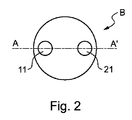
図1は、容器内に包装できるように、2つの液状又はペースト状の製品を送出するための、当該技術分野において既知である、いくつかのオリフィス11、21を備える、ノズルBを、図2に見られる平面AAに沿った断面図で、図式的に示している。包装は典型的には、透明又は半透明であり得る容器において行われてもよい。
FIG. 1 shows a nozzle B comprising
図2は、図1に示されるノズルの1つの面を図式的に例示しており、この面上にいくつかのダクトが開いて、ノズルのオリフィス12、22を形成している。
FIG. 2 schematically illustrates one face of the nozzle shown in FIG. 1, on which several ducts are opened to form
第1オリフィス11へと開いている第1ダクト1は、第1のペースト状の又は液状製品P1を注出するよう意図されている。第2オリフィス21へと開いている第2ダクト2は、第1のペースト状の又は液状製品P2を注出するよう意図されている。
The first duct 1 that opens to the
第1製品及び第2製品P2は、互いに高度に対照的であり得る。この対照は、例えば、色、味、質感、粘度、オーバーラン(overrun)など、製品P1及びP2の1つ以上の感覚刺激特性から生じ得る。いずれにせよ、第1製品P1及び第2製品P2は、互いに異なる。好ましくは、第1製品P1及び第2製品P2は、食品製品、例えば、乳製品デザートに使用される調製物である。 The first product and the second product P2 may be highly in contrast to each other. This control may arise from one or more sensory stimulation properties of products P1 and P2, such as color, taste, texture, viscosity, overrun, and the like. In any case, the first product P1 and the second product P2 are different from each other. Preferably, the first product P1 and the second product P2 are preparations used for food products, for example dairy desserts.
非限定的な例として、第1製品P1及び第2製品P2は、互いに異なり、以下の:
ピューレ、コンポート、クーリ、又はシロップなど、主にフルーツ系の調製物;
ヨーグルト、フレッシュチーズ、クオーク、クリームなど、任意により風味を付けた乳製品調製物;
チョコレートプリン、バニラプリン、カラメル、チョコレートムース、ゼリーなど、ペースト状の調製物から選択される。
As a non-limiting example, the first product P1 and the second product P2 are different from each other and are:
Mainly fruit-based preparations such as puree, compote, courier or syrup;
Optionally flavored dairy preparations such as yogurt, fresh cheese, quark, cream;
It is selected from pasty preparations such as chocolate pudding, vanilla pudding, caramel, chocolate mousse and jelly.
例えば、及び非限定的に、計量される2つの製品は、チョコレートプリン及びバニラプリン、赤色のフルーツクーリ及びフレッシュチーズ、又は白い乳製品ムース及びカラメルクーリであり得る。 For example, and without limitation, the two products to be weighed can be chocolate pudding and vanilla pudding, red fruit cucumber and fresh cheese, or white dairy mousse and caramel cucumber.
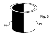
図3は、最終製品、すなわち、図1及び図2に示されるノズルを備えるコメータリング装置を使用して得ることができる、典型的には透明である容器内のいくつかのペースト状の又は液状製品のコメータリングから得られる製品を図式的に示している。図3に示される例は、最終製品がとり得る最も単純な外観(すなわち、容器内で同じ数量で横並びにされた第1製品P1及び第2製品P2の分配)と対応している。第1オリフィス11及び第2オリフィス21は、本明細書において丸い口を備えるものとして示される。しかしながら、製品のための最終的な所望の外観による、任意の口の形状が想到され得る。
FIG. 3 shows several pasty or liquid in a container that is typically transparent, which can be obtained using the end product, ie, a metering device comprising the nozzle shown in FIGS. Fig. 3 schematically shows a product resulting from product commingling. The example shown in FIG. 3 corresponds to the simplest appearance that the final product can take (ie, the distribution of the first product P1 and the second product P2 placed side by side in the same quantity in the container). The
一般的に、コメータリング分野において、容器内における異なる製品の混合を避け、容器内のコメータリングした製品を所望の方法で分配するため、一定のノウハウが必要である。 In general, in the field of metering, certain know-how is required to avoid mixing different products in the container and to distribute the metered product in the container in the desired manner.
当然、異なるペースト状の又は液状製品の容積を計量及び分配するための、良好な技能を有する必要があるが、計量部材中において、ノズルのオリフィスを通じた容器内への放出の間、これらの異なる製品の流れの良好な技能を有することがまた、特に必要である。 Of course, it is necessary to have good skills to meter and dispense different pasty or liquid product volumes, but in the metering member these differ during discharge into the container through the nozzle orifice. It is also particularly necessary to have good product flow skills.
例えば、これらの製品の放出速度は、これらの混合を避けるために、制御及び低減される必要がある。 For example, the release rate of these products needs to be controlled and reduced to avoid mixing them.
工業用機械により必要とされる計量時間はまた、主な制約要因となる。実際、より高い生産性のため、計量動作の全てが、短い周期(多くの場合は2秒未満、又は更に1秒未満)に従って行われなければならない。 The metering time required by industrial machines is also a major limiting factor. In fact, for higher productivity, all metering operations must be performed according to a short period (often less than 2 seconds, or even less than 1 second).
計量の機械化はまた、主要な工業的制約要因であるが、これは計量装置がいわゆるマルチトラックライン(すなわち、いくつかの容器が同時に充填される)において一般的に使用されるためである。このような工業的計量ラインにおいて、一般的に、10〜24個以上の容器が、同時に計量される。したがって、ライン上の容器の上に、充填される容器と同じ数の装置が並置され得るように、計量装置は小型でなくてはならない。 Weighing mechanization is also a major industrial constraint because it is commonly used in so-called multi-track lines (ie, several containers are filled simultaneously). In such an industrial weighing line, generally 10 to 24 or more containers are weighed simultaneously. Therefore, the weighing device must be small so that as many devices as the containers to be filled can be juxtaposed on top of the containers on the line.
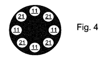
当然、図3に示されるよりも多くのオリジナルの外観が得られ、これを行うための様々な手段及び方法が当該技術分野において既知である。例えば、2つのオリフィスを有する代わりに、ノズルBは、図4に示されるように、より多いオリフィスを有してもよい。実際、ノズルBは、各オリフィスが、第1製品P1又は第2製品P2のいずれかを放出するように、構成されている。したがって、ノズル内には、第1オリフィス11のセット内に開く第1ダクト1のセット及び第2オリフィス21のセット内に開く第2ダクト2のセットが存在する。
Of course, more original appearance is obtained than shown in FIG. 3, and various means and methods for doing this are known in the art. For example, instead of having two orifices, nozzle B may have more orifices, as shown in FIG. In fact, the nozzle B is configured such that each orifice emits either the first product P1 or the second product P2. Thus, within the nozzle, there is a set of first ducts 1 that open into the set of
当該技術分野において既知であり、かつ図4に示される実施形態に従い、ノズルBは円形に構成された8つのオリフィスを含んでおり、製品P1を分配する1つのオリフィスが、これと直接隣接し、第2製品P2を分配するように意図された2つのオリフィスの間にあるようになっている、及びその逆である。 In accordance with the embodiment known in the art and shown in FIG. 4, nozzle B includes eight orifices configured in a circle, with one orifice that dispenses product P1 directly adjacent thereto, It is intended to be between two orifices intended to dispense the second product P2, and vice versa.
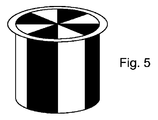
図4に示されるノズルを使用して得ることができる、透明な容器内の最終製品の外観が、図5に示されている。第1製品P1及び第2製品P2は、ノズルが有するオリフィスと同じ数の垂直セクター内に分配される。この場合において、ここで示される例においては、各オリフィスにより等しい量で製品が放出されるが、容器内の最終製品は、第2製品P2の4つのセクターと交互に円形を成す第1製品P1の4つのセクターを有する。 The appearance of the final product in a transparent container that can be obtained using the nozzle shown in FIG. 4 is shown in FIG. The first product P1 and the second product P2 are distributed in the same number of vertical sectors as the orifices of the nozzles. In this case, in the example shown here, each orifice discharges an equal amount of product, but the final product in the container is a first product P1 which is circular with alternating four sectors of the second product P2. There are four sectors.
製品の螺旋状の積層体はまた、その充填中に容器を回転させることにより、任意の方法で得られる。 A spiral laminate of the product can also be obtained in any way by rotating the container during its filling.
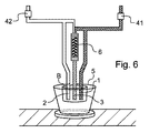
図6は、本発明の一実施形態による、液状及び/又はペースト状の製品をコメータリングするための装置を図式的に示している。 FIG. 6 schematically shows an apparatus for metering liquid and / or pasty products according to an embodiment of the invention.
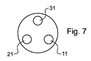
装置は、第1計量ユニット31及び第2計量ユニット32を含む。第1計量ユニット41及び第2計量ユニット42は、正確な量の製品を容器5に導入し、製品の流れを正確に制御することを可能にする。
The apparatus includes a first weighing
製品を制御するために最も一般的に使用される、計量機器は、容積型ポンプである。最も適切なものは、ピストン原理に基づくものである。ピストンの運動は、計測される容積を決定し、動的軸推進速度は、動的な吸引及び放出を決定する。実際、推進及び吸引速度を制御することは重要である。放出速度は、出口における製品流を管理することを可能にし、吸引速度は、ピストンチャンバに製品を適切に充填することを可能にし、これは、各周期において導入される分量の適切な規則性を保証する。吸引速度はそれでも、計量された製品の構造破壊を避けるために、制御及び調節されなくてはならない。 The most commonly used metering device to control the product is a positive displacement pump. The most appropriate one is based on the piston principle. The motion of the piston determines the measured volume, and the dynamic axial propulsion speed determines the dynamic suction and release. In fact, it is important to control the propulsion and suction speed. The discharge rate makes it possible to manage the product flow at the outlet, and the suction rate allows the piston chamber to be properly filled with product, which gives the proper regularity of the quantity introduced in each cycle. Guarantee. The suction speed must still be controlled and adjusted to avoid structural destruction of the weighed product.
その他の種類のポンプもまた使用され得る。いわゆる容積型プッシュポンプは、特に適切である。容積型ポンプは、チャンバの容積の増加に続く、減少を原理として作用する。容積型ポンプの中でも、ローブポンプ(lobe pumps)、正弦ポンプ、膜ポンプ、螺旋ポンプが既知である。典型的には、偏心ローター型の容積型ポンプが使用され得る。一般的にもモーノポンプを参照する。これらは充填された(固体粒子を含む)及び/又は非常に粘性の製品に特に適している。容積型ポンプの中で、いわゆるローブ又は蠕動ポンプもまた、コメータリングのために良好に使用され得る。 Other types of pumps can also be used. So-called positive displacement push pumps are particularly suitable. The positive displacement pump works on the principle of a decrease following an increase in the volume of the chamber. Among positive displacement pumps, lobe pumps, sinusoidal pumps, membrane pumps and spiral pumps are known. Typically, an eccentric rotor type positive displacement pump can be used. In general, reference is also made to the MONO pump. They are particularly suitable for filled (including solid particles) and / or very viscous products. Among positive displacement pumps, so-called lobe or peristaltic pumps can also be successfully used for metering.
本発明による装置において、第1計量ユニット31は、第1製品P1を測定するように構成されている。装置はしたがって、第1計測ユニット41の第1製品P1を供給するのを可能にする。第2計測ユニット42は、第2製品P2を計測するように構成されている。装置はしたがって、第2計測ユニット32の第2製品P2の供給を可能にする。
In the device according to the invention, the first weighing
装置は製品を放出するためのノズルBを含む。ノズルは第1ダクト1及び第2ダクト2を含み、これらはそれぞれ、第1計量ユニット41により第1製品P1を、第2計量ユニット42によって第2製品P2を供給される。本発明において、ノズルは、第3ダクト3を含む。第1ダクト1は、ノズルBの第1オリフィス11へと開き、第2ダクト2はノズルBの第2オリフィス21へと開き、第3ダクトは、ノズルの第3オリフィス31へと開いている。
The device includes a nozzle B for discharging the product. The nozzle includes a first duct 1 and a
第3ダクト3は、第1計量装置41によって及び第2計量装置42によって提供され、第3オリフィスは、第1製品P1及び第2製品P2の混合物M3を放出するようになっている。混合物M3は、第1製品P1及び第2製品P2が異なる色及び/又は明確に異なる質感により高度に対照的であるかぎり、第1製品P1及び第2製品P2のものとは非常に異なる、陰影、色合い及び/又は質感を有し、これが厳密には第3製品を含むという印象をもたらす。
The
混合物M3は、均質であってもよく、又は第1製品P1及び第2製品P2の部分的な混合物であってもよい。第1製品P1及び第2製品P2の割り合いは、混合物M3の所望の外観又は質感を得るようになり得る。 The mixture M3 may be homogeneous or may be a partial mixture of the first product P1 and the second product P2. The proportion of the first product P1 and the second product P2 can come to obtain the desired appearance or texture of the mixture M3.
第1製品及び第2製品P2の適切な混合を生じるために装置が使用されてもよい。静的ミキサ6が使用されてもよい。これは典型的には、第1計量ユニット41及び第2計量ユニット42によって提供される導管内において、第3ダクト3内、又は第3ダクトの上流に、設置されてもよい。
An apparatus may be used to produce proper mixing of the first product and the second product P2. A
図6に記載される装置は、図8に図式的に示される外観を有する最終製品を得ることを可能にする。第1製品P1、第2製品P2及び混合物M3は、3つの垂直セクターに分配される。 The apparatus described in FIG. 6 makes it possible to obtain a final product having the appearance schematically shown in FIG. The first product P1, the second product P2 and the mixture M3 are distributed in three vertical sectors.
ノズルBと容器5との間に相対運動を生じることにより、よりオリジナルで魅力的な外観を得ることが可能である。例えば、図6に示される装置において、容器は、計量装置によりこれを充填する間に、ホルダを回転させることによって回転される。これにより図9に図式的に示される外観を有する最終製品(すなわち、三重螺旋で積み重ねた製品を有する)を得ることが可能である。 By producing a relative movement between the nozzle B and the container 5, it is possible to obtain a more original and attractive appearance. For example, in the apparatus shown in FIG. 6, the container is rotated by rotating the holder while filling it by the metering device. This makes it possible to obtain a final product (ie having products stacked in a triple helix) having the appearance schematically shown in FIG.
図6に示される装置の多くの代替物は、本発明の範囲から逸脱することなく設計することができる。典型的には、ノズルBは4つ以上のダクト及び4つ以上のオリフィスを有し得る。したがって、図11に示されるノズル自体は、8つのオリフィスを有し、この場合、第1製品P1を放出する2つの第1オリフィス11、第2製品P2を放出するための4つの第2オリフィス21及び混合物M3を放出するための2つの第3オリフィス31を有する。更に、特に第3ダクト3が形成され、製品が供給される方法に関し、本発明のいくつかの代替が想到され得る。アセンブリをより小型にするため、かつ2つの計量ユニットを備えた既存のラインを容易に適合することができるように、混合物M3は、ノズルBの第3ダクト内に直接形成されてもよい。
Many alternatives to the apparatus shown in FIG. 6 can be designed without departing from the scope of the present invention. Typically, nozzle B may have 4 or more ducts and 4 or more orifices. Accordingly, the nozzle itself shown in FIG. 11 has eight orifices, in this case, two
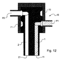
図10は更に、本発明の一実施形態において、いくつかのオリフィス11、21、31(この場合においては8つのオリフィス)を備えるノズルを図式的な断面図で示している。図10は実際に、第1ダクト1を通る断面及び第3ダクト3を通る断面を、同じ図を示すために、図11に示される扇型A−A’に沿った2つの断面で示している。
FIG. 10 further illustrates in schematic cross-section a nozzle comprising
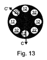
図12は、図13の扇型C−C’によって画定される2つの平面に沿って、図10及び図11に示されるものと同じノズルを、図式的断面図で示している。したがって同じ図は、第1ダクト1を通る断面及び第2ダクト2を通る断面を示している。
FIG. 12 shows in schematic cross section the same nozzle as shown in FIGS. 10 and 11 along two planes defined by the sector C-C ′ of FIG. 13. Thus, the same figure shows a cross section through the first duct 1 and a cross section through the
図10〜13に示されるノズルには、ノズルの2つの別個の区分において、第1計量ユニット41及び第2計量ユニット42によりそれぞれ、第1製品P1及び第2製品P2が供給される。各区分は周辺溝部、すなわち、第1周辺溝部71及び第2周辺溝部72を含む。各第1、第2、又は第3ダクトはそれぞれ、第1周辺溝部71、第2周辺溝部72、又は第1周辺溝部71及び第2周辺溝部72のそれぞれを軽く叩くことによって提供される。
The nozzles shown in FIGS. 10-13 are supplied with a first product P1 and a second product P2, respectively, by a
図10〜13に示されるノズルの使用により、図14に図式的に示される外観を有する最終製品を得ることを可能にする。第1製品P1、第2製品P2及び混合物M3は、ノズルのオリフィスと同数の垂直方向の扇型で分配され、扇型の分布は、ノズルBのオリフィスの分布によって画定される。 Use of the nozzles shown in FIGS. 10-13 makes it possible to obtain a final product having the appearance schematically shown in FIG. The first product P1, the second product P2 and the mixture M3 are distributed in the same number of vertical fan shapes as the nozzle orifices, the fan distribution being defined by the nozzle B orifice distribution.
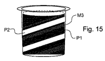
ノズルBと容器5との間の相対的回転運動により、図15に示される外観を有する最終製品を有することが可能となる。第1製品P1、第2製品P2及び混合物M3は、ノズルBのオリフィスの分布に従い、螺旋状に積層される。 The relative rotational movement between the nozzle B and the container 5 makes it possible to have a final product having the appearance shown in FIG. The first product P1, the second product P2, and the mixture M3 are spirally stacked according to the orifice distribution of the nozzle B.
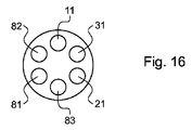
本発明の別の実施形態により、装置は、第3製品を計量するための第3計量ユニットを含み得る。図16に示されるように、多数のオリフィスを含むノズルBは、第1製品P1を放出するための第1オリフィス11に加えて、第2製品P2を放出する第2オリフィス、混合物M3を放出するための第3オリフィス31、第3製品を放出するための第4オリフィス81を有する。第3製品はその後、第4オリフィス81へと開く、装置の第4ダクト内で循環する。
According to another embodiment of the invention, the apparatus may include a third weighing unit for weighing a third product. As shown in FIG. 16, the nozzle B including a plurality of orifices discharges a mixture M3, a second orifice that discharges the second product P2, in addition to the
本発明の様々な実施形態により、固有の陰影、色及び/又は質感を備える、できるだけ多くの混合物を得るため、第1、第2及び第3製品のいくつかの組み合わせられてもよい。異なる陰影、色及び/又は質感の最大7つの製品(又は混合物)は、コメータリング装置が、異なる製品:1)第1製品P1、2)第2製品P2、3)第3製品P3、4)第1製品P1及び第2製品P2の混合物M3、5)第1製品P1及び第3製品P3の別の混合物、6)第2製品P2及び第3製品P3の別の混合物、7)3つの製品の別の混合物をそれぞれ供給された3つの計量ユニットを含むときに、ノズルBによってもたらされ得る。 Various embodiments of the present invention may combine several of the first, second and third products in order to obtain as many mixtures as possible with unique shadows, colors and / or textures. A maximum of seven products (or mixtures) with different shades, colors and / or textures are produced by different metering devices: 1) 1st product P1, 2) 2nd product P2, 3) 3rd product P3, 4) Mixture M3 of the first product P1 and the second product P2, 5) Another mixture of the first product P1 and the third product P3, 6) Another mixture of the second product P2 and the third product P3, 7) Three products Can be provided by nozzle B when it includes three metering units, each fed with another mixture.
図16に示される例において、6つの製品又は混合物が、提供されてもよく、上述のノズルオリフィスに加えて、ノズルは、第5オリフィス81及び第6オリフィス82を有し、装置は、本明細書において示される例において、第5オリフィス81を通じて第1製品P1及び第3製品P3の混合物を、第6オリフィス82を通じて第2製品P2及び第3製品P3の混合物を分配するように構成されている。
In the example shown in FIG. 16, six products or mixtures may be provided, in addition to the nozzle orifices described above, the nozzle has a
このような装置の構成において、いくつかの製品の混合物を分配するように意図されたノズルの各ダクトは、静的ミキサなどの混合手段を備えていてもよい。 In such a device configuration, each duct of the nozzle intended to dispense a mixture of several products may be provided with mixing means such as a static mixer.
装置は、ダクトの少なくとも1つのための、逐次的な供給手段(図示されない)を含んでもよい。換言すると、装置は、一定のダクトの供給及びしたがって、上記逐次的供給手段の1つを介して供給されるダクトのいずれか1つ以上による、製品又は混合物の供給を、を急激に、又は段階的に停止及び再開するための手段を含んでもよい。逐次的供給手段は例えば、適切な計量ユニットを駆動する手段を含む。これらもまた、又は代替的に、コメータリング中における所与のダクトにおける製品(又は混合物)の流れを中断するために、例えば、ソレノイド弁などの分配弁を含んでもよい。 The apparatus may include sequential supply means (not shown) for at least one of the ducts. In other words, the apparatus abruptly or stages the supply of a constant duct and thus the supply of the product or mixture by any one or more of the ducts supplied via one of the sequential supply means. Means for automatically stopping and resuming may be included. The sequential supply means includes, for example, means for driving a suitable metering unit. These may also or alternatively include a distribution valve, such as a solenoid valve, for example, to interrupt the flow of product (or mixture) in a given duct during the metering.
本発明はしたがって、典型的には、2つの製品のみを計量するために設けられ、2つの計量ユニットのみを備える、包装ラインにおいて、3つの製品を含むように、視覚的に(又は質感において)見える、最終製品を得ることを可能とする。 The present invention is therefore visually (or in texture) to include three products in a packaging line which is typically provided for weighing only two products and comprises only two weighing units. Makes it possible to get the final product visible.
本発明はしたがって、多くの製品、特に食品製品の製造に適用可能である。例えば、バニラプリン及びダークチョコレートプリンでは、バニラプリン、ミルクチョコレートプリン及びダークチョコレートプリンという、3つの別個の製品を含むように見える最終製品を得ることが可能である。同様に、ホワイトチーズ及び赤いフルーツクーリでは、ホワイトチーズ及びイチゴチーズを含み、赤いクーリのラインで大理石模様にされているように見える最終製品を得ることが可能である。白い乳製品ムース及びカラメルは、暗いカラメルの縞模様がある、白いムース及びクリカラメルムースが並置されるのを示している最終製品を得ることが可能である。 The present invention is therefore applicable to the manufacture of many products, particularly food products. For example, with vanilla pudding and dark chocolate pudding, it is possible to obtain a final product that appears to contain three separate products: vanilla pudding, milk chocolate pudding and dark chocolate pudding. Similarly, with white cheese and red fruit cucumber, it is possible to obtain a final product that includes white cheese and strawberry cheese and appears to be marbled with a line of red cucumber. White dairy mousse and caramel can obtain a final product with dark caramel stripes, showing white mousse and chestnut caramel mousse juxtaposed.
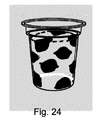
本発明はしたがって、比較的単純な装置を使用した、この分野において未知である、態様の多様性を得ることを可能にする。本発明を、液状又はペースト状の製品を計量又はコメータリングする分野における一定の方法又はノウハウと組み合わせることにより、広範な新規の、又は魅力的態様が得られる。技能が重要である一定のパラメータが以下に記載され、これらのパラメータを習得することによって得られる最終的な製品の様々な態様又はパターンが図17〜27に示されている。 The present invention thus makes it possible to obtain a variety of aspects that are unknown in the field, using relatively simple devices. By combining the present invention with certain methods or know-how in the field of metering or metering liquid or pasty products, a wide range of novel or attractive aspects can be obtained. Certain parameters where skill is important are described below, and various aspects or patterns of the final product obtained by mastering these parameters are shown in FIGS.
パラメータは、計量される製品の特性、計量装置の設計(全体的構造、計量技術の選択、又はノズルの設計)、装置の制御及び計量中にノズルと充填された容器との相対位置の制御を考慮することに関する。 Parameters include the characteristics of the product to be weighed, the design of the weighing device (overall structure, choice of weighing technology, or nozzle design), control of the device and control of the relative position between the nozzle and the filled container during weighing. Related to consideration.
計量される製品のレオロジーは、正確に考慮されなくてはならない。実際、計量される製品の粘度、又はレオロジー挙動の違いは、コメータリングの困難さを増加させる。多くのレオロジー挙動パラメータが考慮される必要があり、製品は、粘性又は液状、ベタベタ又はつるつる、泡状又は非泡状であり得る。同じレオロジー挙動を有する2つの半粘性製品はコメータリングしやすいが、非常に流動性の高い製品及び非常に粘性の製品による場合、又は非常に高密度の製品が空気の多いムース内で計量される場合、状況はより複雑なものとなる。密度の違いは、一定の状況においては、2つの製品を分離するために有利に使用され得る。例えば、これは容器の底部で急速に固化するゲル状ミルク内のカラメルを計量する場合に妥当する。 The rheology of the product to be weighed must be accurately taken into account. In fact, differences in the viscosity or rheological behavior of the product being weighed increase the difficulty of commuting. Many rheological behavior parameters need to be considered, and the product can be viscous or liquid, solid or slippery, foamy or non-foamed. Two semi-viscous products with the same rheological behavior are easy to meter, but with very fluid and very viscous products, or very dense products are metered in an airy mousse If so, the situation becomes more complicated. The difference in density can be advantageously used to separate the two products in certain situations. For example, this is appropriate when weighing caramel in gelled milk that solidifies rapidly at the bottom of the container.
推進及び吸引速度を制御するため、単純な空気ピストン、又は単純な電気モーターは最適ではない。サーボモータシステムを使用した、自動デジタルシステムを使用したモーター化が好ましい。これは、所望の製品の流れを得るために計量された製品の特性にこれらを適合するために、ポンプの可動要素(典型的には、ピストンの運動軸)の加速及び運動時間を管理することを可能にする。このようなモーター化及び自動化による管理は計量ユニットのそれぞれの同期を可能にする。大きく異なる粘度を有する2つの製品を押す際、例えば、ノズルノーズからの両方の製品を同時に出すために、より粘性の高いものを押すことを予測するのが適切である。 Simple air pistons or simple electric motors are not optimal for controlling propulsion and suction speeds. Motorization using an automatic digital system using a servo motor system is preferred. This manages the acceleration and movement time of the pump's moving elements (typically the axis of motion of the piston) to adapt them to the characteristics of the product weighed to obtain the desired product flow. Enable. Such motorized and automated management allows the respective weighing units to be synchronized. When pushing two products with vastly different viscosities, it is appropriate to predict pushing more viscous ones, for example, to deliver both products from the nozzle nose at the same time.
各製品料と関連するピストンの別個のモーター化が有利に使用される。 A separate motorization of the piston associated with each product charge is advantageously used.
吸入弁の開放及び閉鎖時間及び計量ユニット及びノズルからの放出は、各計量ユニットによる製品の押出とは別個に、有利に駆動される。 The opening and closing times of the intake valves and the discharge from the metering units and nozzles are advantageously driven separately from the product extrusion by each metering unit.
コントローラに一体化されたパラメータの品質により、典型的には各製造操作者のために、明確な手続きをもたらし、計量装置の調節ためのセーフガード及び回収手段をもたらすことが望ましい。これは、所望のコメータリングの結果を確実に、繰り返し得るのを可能にする。 Due to the quality of the parameters integrated into the controller, it is desirable to provide a clear procedure, typically for each manufacturing operator, and to provide safeguards and recovery means for adjusting the metering device. This makes it possible to ensure that the desired result of the metering can be obtained repeatedly.
それでも、古いコメータリング装置は多くの場合、例えば、共有される駆動バーによって、一連のピストン計量ユニットの単一のモーター化を実行する。これらの装置の問題の1つは、様々なピストンにより変位する体積の制御性の低さにある。実際、ピストン計量ユニットにより吸引される体積は、製品分配システムにおいて一般的に見られる、圧力差(たとえ、極僅かでも)に対して敏感である。更に単一の駆動バーでは、他の計量ユニットの設定を変更することなく、特定の計量ユニットを個別に調節することは不可能である。この問題を可決するために追加的なシステムが使用される。例えば、ピストンの運動の更なる調節を可能にするため、機械部品が追加されてもよい。別のシステムにより、所与の計量ユニットにより計量される製品が被る圧力損失は、計量における圧力差の効果を補正するために調節される。 Nevertheless, older commetering devices often perform a single motorization of a series of piston metering units, for example by means of a shared drive bar. One of the problems with these devices is the poor controllability of the volume displaced by the various pistons. In fact, the volume drawn by the piston metering unit is sensitive to pressure differences (even very little) commonly found in product dispensing systems. Furthermore, with a single drive bar, it is not possible to individually adjust a particular weighing unit without changing the settings of other weighing units. An additional system is used to pass this problem. For example, mechanical parts may be added to allow further adjustment of piston movement. With another system, the pressure loss experienced by the product weighed by a given metering unit is adjusted to compensate for the effect of the pressure difference on the metering.
製品のコメータリングにおいて制御されるべき重要な態様の1つは、計量される製品又は混合物の流速である。この態様に影響する重要なパラメータの1つは、使用される直径、形状、断面、ホース及びダクト、並びにノズルオリフィスの選択である。これは、適切な流路断面を計算することによって流速を適切することを含む。過剰な加速によって製品が剪断される(これは製品の変性を生じることがある)のを防ぐことを可能にし、これは場合によって計量される製品又は混合物に対し、これの放出中に、容器内でこれを方向付けるために有用なエネルギーを付与することを可能にする。更に、異なるコメータリングされた製品の混合を避けるため、製品の各排出速度が比較的近いままであることが望ましい。製品が層状のままであることを確実にすることも重要である。典型的には、0.5m/秒の速度のときに、容器の底部及び流体の混合を生じる流体の運動に最も影響を与えやすい。一般的に、0.5〜0.25m/秒が、工業的コメータリング方法の、適度な流速を形成する。 One important aspect to be controlled in product metering is the flow rate of the product or mixture being metered. One of the important parameters affecting this aspect is the choice of diameter, shape, cross section, hoses and ducts used, and nozzle orifices. This includes adjusting the flow rate by calculating the appropriate channel cross section. It makes it possible to prevent the product from being sheared by excessive acceleration (this can lead to denaturation of the product), which in the container during discharge of the optionally metered product or mixture Makes it possible to apply useful energy to orient this. In addition, it is desirable that each product discharge rate remain relatively close to avoid mixing differently metered products. It is also important to ensure that the product remains layered. Typically, at a speed of 0.5 m / sec, it is most likely to affect the movement of the fluid resulting in mixing of the bottom of the container and the fluid. In general, 0.5 to 0.25 m / sec forms a reasonable flow rate for an industrial co-metering process.
出願者は更に、製品の流れの動力学(速度、加速)が、最終製品の様々な視覚的対応につながることに気づいた。 Applicants have further realized that product flow dynamics (speed, acceleration) lead to various visual correspondences of the final product.
更に、製品流の制御は一般的に、過剰な圧力損失により中断されることが多い。これらの圧力低下は多くの場合、計量ノズルよりかなり上流の、装置の技術的設計における適切な技能に依存する。パイプ及びホースの直径の選択は重要であり、様々な製品の粘度に依存する。エルボー、弁及び圧力低下の原因となる他の装置又は構成を低減することも適切である。 Furthermore, product flow control is often interrupted by excessive pressure losses. These pressure drops often depend on appropriate skills in the technical design of the device, well upstream from the metering nozzle. The selection of pipe and hose diameters is important and depends on the viscosity of the various products. It is also appropriate to reduce elbows, valves and other devices or configurations that cause pressure drops.
コメータリング製品それぞれが経験する異なる圧力低下は、ノズル出口における製品の非同時的な到達を生じ得る。よって放出される製品流を正確に制御するのは困難である。 The different pressure drops experienced by each commuter product can result in a non-simultaneous arrival of the product at the nozzle outlet. Thus, it is difficult to accurately control the product stream that is released.
計量又はコメータリング装置の各計量ユニットは一般的に、ホッパーにより計量される製品を供給される。計量機器の様々な部品を提供する、ホッパー内の製品濃度のばらつきは、流れの規則性に悪影響を及ぼし得る。ホッパー内で一定の濃度を維持するために製品の供給を調節することは、流れの良好な規則性を得るために正の要因である。 Each weighing unit of a weighing or metering device is generally supplied with a product to be weighed by a hopper. Variations in product concentration within the hopper that provide the various parts of the weighing equipment can adversely affect flow regularity. Adjusting the product supply to maintain a constant concentration in the hopper is a positive factor to obtain good flow regularity.
更に、同じホッパー内の圧力の良好な制御は、計量、又はコメータリング方法の残りにおけるより高い一貫性をもたらす。典型的に、ホッパー内に空気の加圧を形成することにより、圧力を生成し、一定の圧力を維持するための機器は、ホッパー内の圧力を正確に制御するために使用され得る。これは、例えば、空気混入した製品及びフォームなど、圧縮性製品を計量又はコメータリングするときに、特に有用であり、実用的である。 Furthermore, a good control of the pressure in the same hopper results in a higher consistency in the rest of the metering, or metering method. Typically, equipment for generating pressure and maintaining a constant pressure by creating an air pressurization in the hopper can be used to accurately control the pressure in the hopper. This is particularly useful and practical when metering or metering compressible products, such as, for example, aerated products and foams.
計量ユニットの上流における圧力損失は、重要な態様を形成する。実際、ホッパーと、計量部材(例えば、ピストンポンプ)との間のダクト(不十分な直径、多くのエルボーの存在)の不適切な設計による過剰な圧力損失は、下流で得られる結果、したがって計量品質に悪影響を与え得る。それぞれノズルを提供するいくつかの計量ユニットを含むシステムにおいて、計量ユニットの上流における圧力損失の不均衡は、計量ユニットそれぞれによって計量される体積の不均衡を生じる。いくつかの装置は、不均衡を低減させるか、又は圧力損失を平衡させるのを可能にする。また、計量ユニット、典型的にはピストン計量ユニットが、計量された製品をホッパー内に直接引くように、装置を構成することが可能である。 The pressure loss upstream of the metering unit forms an important aspect. In fact, excessive pressure loss due to improper design of the duct (insufficient diameter, presence of many elbows) between the hopper and the metering member (eg piston pump) is a result obtained downstream and therefore metered Can adversely affect quality. In a system including several metering units each providing a nozzle, an imbalance in pressure loss upstream of the metering unit results in an imbalance in the volume metered by each metering unit. Some devices make it possible to reduce imbalances or to balance pressure losses. It is also possible to configure the device such that a weighing unit, typically a piston weighing unit, pulls the weighed product directly into the hopper.
計量ユニットの下流における圧力損失は、別の重要な態様を形成する。実際、圧力損失は、製品の適切な流れを分断し得る。計量部材と計量ノズルとの間の分断は、最小の潜在的圧力損失を生じる傾向を有するべきである。圧力損失は特に、計量ユニットと放出ノズルとの間の距離に関連し、これは計量装置の一般的構造によって決定される。計量ユニットと、ノズルとの間の圧力損失を制限するため、1つの単純な解決法は、上記の計量ユニットを、ノズル及び容器に真っ直ぐ、かつできるだけ近く位置付けることを含む。装置が全体的に小型であることが、したがって重要である。 Pressure loss downstream of the metering unit forms another important aspect. In fact, pressure loss can disrupt the proper flow of the product. The break between the metering member and the metering nozzle should have a tendency to produce minimal potential pressure loss. The pressure loss is particularly related to the distance between the metering unit and the discharge nozzle, which is determined by the general structure of the metering device. In order to limit the pressure loss between the metering unit and the nozzle, one simple solution involves positioning the metering unit straight and as close as possible to the nozzle and container. It is therefore important that the device is entirely small.
しかしながら、このような解決法は、可動ノズルと両立させることが難しい。更に、容器の上に位置付けられた計量ユニットを備えるこの構成はまた、いわゆる「衛生的」なマシンの設計を複雑にする。 However, such a solution is difficult to make compatible with a movable nozzle. Furthermore, this arrangement with a weighing unit positioned on the container also complicates the design of so-called “hygienic” machines.
実際、衛生目的のために層状の流れが使用される、これらの超清浄包装マシンにおいて、計量ユニットを、包装エンクロージャ(容器のための充填ラインを含む)の外側にこれらの可動部品とオフセットすることが好ましい。計量ピストンはしたがって、包装される容器と垂直に位置する自由空間のために、包装エンクロージャの外側に配置されることが多い。ノズルのみが包装エンクロージャ内に残り、可撓性及び/又は剛性パイプによって計量ユニットに接続される。これは計量ユニットとノズルとの間に顕著な圧力損失を生じる。 In fact, in these ultra-clean packaging machines where laminar flow is used for hygiene purposes, offset the weighing unit with these moving parts outside the packaging enclosure (including the filling line for containers) Is preferred. The metering piston is therefore often arranged outside the packaging enclosure because of the free space located perpendicular to the container to be packaged. Only the nozzle remains in the packaging enclosure and is connected to the weighing unit by a flexible and / or rigid pipe. This creates a significant pressure loss between the metering unit and the nozzle.
計量ユニットの上流及び下流の残圧もまた、影響のあるパラメータであり、その制御が重要である。計量ユニットの下流における圧力が高い場合、充填中(計量する製品で充填するとき)に、製品の計量チャンバへと逆流が生じる。これは、実際に吸引された体積の正確な情報を歪め、典型的にはポンプの変位と対応しないものとする。この現象を最小化するため、装置は、計量段階(吸引又は放出)において、すぐ上流又は下流におけるゾーンから計量チャンバを分離する、分離弁のシステムを備えてもよい。回転摺動弁タイプの弁が、この目的のために使用されてもよい。 The residual pressure upstream and downstream of the metering unit is also an influential parameter and its control is important. If the pressure downstream of the metering unit is high, there will be a back flow into the product weighing chamber during filling (when filling with the product to be weighed). This distorts the exact information of the volume actually aspirated and typically does not correspond to the displacement of the pump. In order to minimize this phenomenon, the device may comprise a system of separation valves that separates the metering chamber from the zone immediately upstream or downstream in the metering phase (suction or discharge). A rotary sliding valve type valve may be used for this purpose.
一般的に、計量ユニットのすぐ下流にある計量弁を使用せず、オフセットノズルを有する計量装置は、比較的不規則であり、かつ不正確である。この構成において、計量終了時の製品のデッドスペース(すなわち、計量ユニットとノズル閉鎖弁との間に位置付けられる残留体積)は、多くの場合、変位及び計量される製品の量よりも遥かに大きい。 Generally, a metering device that does not use a metering valve immediately downstream of the metering unit and has an offset nozzle is relatively irregular and inaccurate. In this configuration, the dead space of the product at the end of the metering (i.e. the residual volume located between the metering unit and the nozzle closing valve) is often much larger than the amount of product to be displaced and metered.
計量ユニットの下流の残圧は、高速で計量が行われる場合、製品が粘性かつ粘り気がある場合、製品が圧縮性である場合、及びパイプの下流の長さが長い場合に、更に重要である。これらのパラメータの1つ(又は組み合わせ)が、高い残圧を生じる場合、計量のための押圧の終了時と、圧力均衡までの戻りとの間に必要な時間は最少である。この現象は、ノズルのオリフィスの出口における、製品のきれいな分断にとって望ましくなく、滴り及び溢れが生じ得る。ムースを計量する場合、例えば、放出操作の間に動的に圧縮されるムースは、計量ユニットを放出ノズルと接続するパイプ内における2つの計量サイクルの間に膨張する傾向がある。 The residual pressure downstream of the metering unit is even more important when metering at high speeds, when the product is viscous and sticky, when the product is compressible, and when the length downstream of the pipe is long . If one (or combination) of these parameters produces a high residual pressure, the time required between the end of the metering press and the return to pressure balance is minimal. This phenomenon is undesirable for clean breakage of the product at the outlet of the nozzle orifice and can cause dripping and overflow. When metering mousses, for example, a mousse that is dynamically compressed during the discharge operation tends to expand between two metering cycles in the pipe connecting the metering unit with the discharge nozzle.
更に、オーバーランにより体積が増加する、粘性の、粘り気のある製品(オーバーラン製品と呼ばれるもの、例えば、ホイップクリーム)の流れは、特に、ノズルの出口オリフィスにおいて、きれいに分断するのが難しい。計量後に製品が膨張すると、例えば、重力によって溢れが生じることがある。 Furthermore, the flow of a viscous, sticky product (called an overrun product, such as whipped cream), which increases in volume due to overrun, is difficult to break cleanly, especially at the nozzle exit orifice. If the product expands after weighing, for example, overflow may occur due to gravity.
この漏れを避け、ノズルオリフィス内のいずれかの圧力を迅速に相殺するためにいくつかの技術が存在する。 Several techniques exist to avoid this leak and quickly cancel any pressure in the nozzle orifice.
これらの技術の1つは、閉鎖弁の高さを放出オリフィスに位置付けることによって、製品の放出を分断させることから成る。したがって、デッドスペース(すなわち、回路内において、閉鎖弁と放出オリフィスとの間の残りのスペース)が、無い、又は実質的に無い。 One of these techniques consists of disrupting product discharge by positioning the height of the shut-off valve at the discharge orifice. Thus, there is no or substantially no dead space (ie, the remaining space between the closure valve and the discharge orifice in the circuit).
ノズルにより単一の製品を、単一のオリフィスへと注入するのに好適な装置の単純な解決法は、ノズルに多数の放出オリフィスが設けられているときに、実施が困難である。 A simple solution of a device suitable for injecting a single product into a single orifice by means of a nozzle is difficult to implement when the nozzle is provided with a large number of discharge orifices.
いくつかの弁システムは、いくつかの放出オリフィスを同時に閉鎖することを可能にするように構成されている。これは典型的には、平坦な膜、球形の膜、複雑に機械加工されたゲート、回転面及びいわゆる「摺動」システムにおいて妥当する。 Some valve systems are configured to allow several discharge orifices to be closed simultaneously. This is typically relevant in flat membranes, spherical membranes, complex machined gates, rotating surfaces and so-called “sliding” systems.
これらの可動部品の洗浄の容易性、これらの摩耗、密封の問題、充填される容器と垂直にこれらの弁を追加することにより生じるバルクは、このようなシステムの適用を特に複雑にする要因であり得る。 The ease of cleaning these moving parts, their wear, sealing problems, and the bulk created by adding these valves perpendicular to the container to be filled are factors that make the application of such a system particularly complex. possible.
溢れを避けるための1つの技術は、計量の終了時の製品を再吸引することから成る。これは、計量サイクルの最後に、放出オリフィスに僅かな負圧を形成することによって行われる。この僅かに低い圧力は例えば、回路に、ノズルの上流に位置付けられた2つの膜弁(例えば、いわゆる「スリーブ」膜タイプ)を設けることによって、生成されてもよい。より低い圧力を生成するため、2つの弁が同時に閉鎖され、その後、下流の方の弁(放出オリフィスの最も近く)が再開放される。この真空は代替的に、開放することにより、回路内の圧力を再び平衡させて、ノズルの放出オリフィスの上流の圧力低下を生じることを可能にする、特定の製品出口によって形成されてもよい。 One technique for avoiding overflow consists of re-aspirating the product at the end of the metering. This is done by creating a slight negative pressure at the discharge orifice at the end of the metering cycle. This slightly lower pressure may be generated, for example, by providing the circuit with two membrane valves positioned upstream of the nozzle (eg, the so-called “sleeve” membrane type). In order to produce a lower pressure, the two valves are closed simultaneously, after which the downstream valve (closest to the discharge orifice) is reopened. This vacuum may alternatively be formed by a specific product outlet that allows opening to rebalance the pressure in the circuit, resulting in a pressure drop upstream of the discharge orifice of the nozzle.
二重空気システムによって支援される、封止部材による閉鎖もまた、このより低い圧力を生成することができ、2つの空気部材の一方が、完全な閉鎖の後に、封止部材を僅かに後方に戻す。適切な設計を有する、回転閉鎖ゲートを使用して計量した直後に、製品の再吸引効果を得ることも可能である。容積回転ポンプを使用する計量システムにおいて、ポンプの短い後方への戻りもまた、この再吸引を可能にし得る。最後に、サーボモータによってピストンのモーター化を行うシステムにおいて、この「再吸引」は、ピストン軸の運動の単純で適切なプログラミングによって行うことができる。 Closing with a sealing member, assisted by a dual air system, can also generate this lower pressure, with one of the two air members slightly pushing the sealing member rearward after complete closure. return. It is also possible to obtain a product re-suction effect immediately after weighing using a rotating closure gate with a suitable design. In a metering system using a volumetric rotary pump, a short backward return of the pump may also allow this re-aspiration. Finally, in a system where the piston is motorized by a servo motor, this “re-suction” can be done by simple and appropriate programming of the movement of the piston shaft.
いくつかの製品のコメータリングの間、ノズルのオリフィスの出口における、製品の放出速度に加えて、容器内へと落下する高さは、製品の混合を避け、容器内の規則的外観を達成することを考慮に入れるために、重要なパラメータである。 During the metering of some products, in addition to the product discharge rate at the outlet of the nozzle orifice, the height falling into the container avoids product mixing and achieves a regular appearance in the container This is an important parameter to take into account.
これらのコメータリングの間における、製品の表面に関するノズルの位置(高さ)を一定に維持することで、規則的な線を形成することが可能となる。これは、プリフォーム容器を使用する、又はマシンのノズルの垂直変位システムを使用する、包装ライン上の容器を上昇させるシステムを使用して、得られる。換言すると、製品の実質的に一定の落下高さを維持するために、容器がノズルに対して移動されるか、又はノズルは容器に対して移動されるかのいずれかである。使用される包装マシンが、「フォームフィルシールと一般的に称されるタイプのものであるとき(すなわち、充填された容器を成形し、これを封止するマシン、特に、いわゆる「水平フォームフィルシール」マシン)、ノズルの運動のためのシステムは特に好適である。落下高さはしたがって、いわゆる垂直図3、5、8及び14に示されるように、いわゆる垂直の、又は区域ごとの計量によって、最終製品を得るために重要なパラメータである。 A regular line can be formed by keeping the position (height) of the nozzle relative to the surface of the product constant between these metering rings. This is obtained using a system that raises the container on the packaging line, using a preform container, or using a vertical displacement system of the machine nozzle. In other words, in order to maintain a substantially constant drop height of the product, either the container is moved relative to the nozzle or the nozzle is moved relative to the container. When the packaging machine used is of the type commonly referred to as “foam fill seal” (ie a machine for molding and sealing filled containers, in particular so-called “horizontal foam fill seals” "Machine", a system for the movement of the nozzle is particularly suitable. The drop height is therefore an important parameter for obtaining the final product by so-called vertical or area-by-zone weighing, as shown in so-called vertical figures 3, 5, 8 and 14.
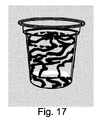
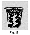
逆に、一定の態様を得るために、製品の落下高さのばらつきを利用することが可能である。典型的に、充填中に、ノズル及び容器を互いに遠ざけるか、又は近づけることによって、製品のより多くの、又はより少ないランダムな落下が生じる。製品はその後、傾いた又は水平の層として組織化し、例えば、図17及び18に示される態様の1つを得ることが可能となる。 Conversely, in order to obtain a certain aspect, it is possible to use the variation in the drop height of the product. Typically, during filling, moving the nozzle and container away from or close to each other will result in more or less random drops of product. The product is then organized as a tilted or horizontal layer, making it possible to obtain, for example, one of the embodiments shown in FIGS.
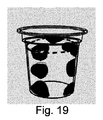
製品の不連続な流れと関連する、計量中におけるノズル及び/又は容器の昇降運動の減速又は中断は、図19に示される態様を得ることが可能となり、別の製品の泡が含まれる、製品を含む最終製品の態様が含まれることを意味する。「ブラシ無しサーボ」と称されるタイプのモーター化は、ノズル及び容器の相対運動を制御することを非常に容易にする。 The slowing or interruption of the lifting movement of the nozzle and / or container during metering, associated with the discontinuous flow of the product, makes it possible to obtain the embodiment shown in FIG. 19 and includes another product foam Is meant to include an embodiment of the final product. A motorization of the type called “brushless servo” makes it very easy to control the relative movement of the nozzle and the container.
更に、容器の中間位置におけるノズルの停止は、コメータリングされた製品の表面を、これに均質な態様を付与することによって、仕上げることを可能にする。計量の終了時における外側オリフィスと、製品との間の僅かな接触の後、上方位置に向かって急激に上昇する運動により、ネバネバし、粘性であり、粘り気のある製品(例えば、ミルクカラメル、ムースなど)の溢れ及び流れを避けることができる。 Furthermore, the stop of the nozzle in the middle position of the container makes it possible to finish the surface of the metered product by giving it a homogeneous aspect. After a slight contact between the outer orifice at the end of the metering and the product, a suddenly upward movement toward the upper position causes the product to be sticky, viscous and sticky (eg milk caramel, mousse) Etc.) can be avoided.
ホイップクリームなど、オーバーランした製品において、例えば、計量の終了時に、ノズルの容器に対する(又はより具体的には、容器内の製品の高さに対する)運動の適切な制御は、最終製品の表面にドーム形状を得ることを可能にする。 In overrun products, such as whipped cream, for example, at the end of weighing, proper control of movement of the nozzle relative to the container (or more specifically to the height of the product in the container) can be achieved on the surface of the final product. It makes it possible to obtain a dome shape.
液体製品において、製品の落下中において、製品の落下とは反対の運動を働かせること及び落下をできるだけ低減することによって、製品落下中のいずれかの飛散効果、又はいずれかの混合のリスクを制限することが可能となる。これは、製品を混合するリスクを最小化することによって、低粘度の製品の上に液体を静かに堆積するために特に重要である。 In liquid products, limit the risk of any splashing effects or any mixing during the product fall by applying the opposite movement to the product drop and reducing the fall as much as possible during the product fall. It becomes possible. This is particularly important for gently depositing liquid on low viscosity products by minimizing the risk of mixing the products.
更に、計量中に、製品の放出動力学の適切な制御と関連する、製品の落下高さを制御することによりまた、例えば、第1製品内に第2製品を、この第1製品の所望の深さに、位置付けることが可能となる。 In addition, during metering, by controlling the drop height of the product in conjunction with the appropriate control of the product release kinetics, for example, the second product in the first product may be It becomes possible to position to the depth.
更に、ノズル及び/又は容器に垂直運動をかけることにより、ノズル及び/又は容器に回転運動を付与し、図9及び図15に示されるように、最終製品の渦巻状又は螺旋状の態様を付与することが可能となる。 Further, by applying a vertical motion to the nozzle and / or container, a rotational motion is imparted to the nozzle and / or container, giving a spiral or spiral aspect of the final product as shown in FIGS. It becomes possible to do.
いくつかの容器が計量され、かつ同時に充填される、大容量マシンにおいて、例えば、いくつかの容器の、関節回転のための歯車又はノッチ付きベルトによる機械的システムなど、いくつかのシステムが、この機能を実行するために想到されてもよい。使用されるシステムは特に、工業的に製造されるペーストの装飾分野において既知のシステムと同様であってもよい。 In large capacity machines where several containers are weighed and filled at the same time, several systems, such as a mechanical system of several containers with gears or notched belts for joint rotation, It may be envisaged to perform the function. The system used may in particular be similar to systems known in the decorative field of industrially produced pastes.
計量サイクル中において、容器又はノズルによって行われる回転数を調節する、回転速度が、広範な螺旋を得ることを可能にする。高い回転数(計量サイクルの持続時間にわたり得ることは困難であるが)は、コメータリングした製品の層をほぼ水平に配置することを可能にする。最終製品は次に、典型的には、図20に示される態様を有する。 During the metering cycle, the rotational speed, which adjusts the number of revolutions performed by the container or nozzle, makes it possible to obtain a wide range of spirals. The high rotational speed (although difficult to obtain over the duration of the metering cycle) allows the layer of the metered product to be placed almost horizontally. The final product then typically has the embodiment shown in FIG.
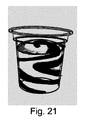
計量中における回転方向における交互の容積は、製品に図21に示されるようにジグザグの螺旋状の態様を付与する。 The alternating volume in the direction of rotation during metering gives the product a zigzag helical form as shown in FIG.
容器に対するノズルの回転又は上昇を制御するためにサーボモータを使用することにより、得られる態様の多様性を更に増加させるように、加速を微調整することが可能となる。上昇中に変動する速度を適用することによって螺旋を垂直に伸ばす、又は逆に、ノズルの上昇速度を間欠的に減速させることによってより広い対照的なゾーンを生成することが可能である。 By using a servomotor to control the rotation or elevation of the nozzle relative to the container, it is possible to fine tune the acceleration so as to further increase the variety of aspects obtained. It is possible to create a wider contrast zone by extending the helix vertically by applying varying speeds during ascent, or conversely by slowing down the nozzle ascent rate intermittently.
ノズルの放出オリフィスの形状、断面、数及び位置が、容器内で製品がどう組織されるかに全て影響するパラメータを形成する。 The shape, cross-section, number and position of the discharge orifice of the nozzle form parameters that all influence how the product is organized in the container.
円形である、オリフィスの分布(ノズルが実質的回転形状を有することを考慮し、ノズルの中心から等間隔である)は、単純な垂直の計量中において、扇型の形状を生じ、製品は直線的に分離し、中心部から容器の周辺部に向かって広がっている。このような分布は、図3、5及び8に示されている。 The distribution of the orifice, which is circular (considering that the nozzle has a substantially rotating shape, is equidistant from the center of the nozzle) produces a fan-shaped shape during simple vertical metering, and the product is straight Separating from the center to the periphery of the container. Such a distribution is shown in FIGS.
コメータリングした製品が非常に異なる粘度を有する場合、ノズルの中心から異なる距離で各製品を放出することをそれぞれ意図された、オリフィスを位置付けるために、製品の分布におけるこのような規則性を得ることが適切である。 Obtaining such regularity in the distribution of products to position the orifices, each intended to emit each product at different distances from the center of the nozzle, if the metered products have very different viscosities Is appropriate.
コメータリングされた製品の1つがノズルの中心に位置するオリフィスを通じて放出される場合、この製品は、容器内において膨張している間に、他の製品を容器の縁部の方に押し戻す傾向があり、横方向のデザインを備える、縞状の分布を生じる。製品の動的な粘度に依存する、所望の結果を得るための、オリフィスの正確な位置は、適切な試行によって一般的得られ、かつ微調整される。 If one of the commuted products is ejected through an orifice located in the center of the nozzle, this product tends to push the other product back towards the edge of the container while expanding in the container. This produces a striped distribution with a lateral design. Depending on the dynamic viscosity of the product, the exact position of the orifice to obtain the desired result is generally obtained and fine tuned by appropriate trials.
更に、製品の1つの放出オリフィスの断面が、この製品に、他の製品よりも高い放出速度を付与するために低減される場合、この製品は、容器内においてジグザグ又は縞状に構成される傾向がある。 Furthermore, if the cross section of one discharge orifice of the product is reduced to give the product a higher release rate than the other products, the product will tend to be zigzag or striped in the container. There is.
異なる製品の放出オリフィスは、単一の平面に位置付けられないことがある。これは、適用可能な場合、計量中及びその終了時において様々な製品の間の接触を避けることが可能にする。このような接触は、局地的な混合により、異なる製品の間の際立った対照性を得ることに反することとなる。 Different product discharge orifices may not be located in a single plane. This makes it possible to avoid contact between the various products during weighing and at the end when applicable. Such contact would be contrary to gaining outstanding contrast between different products due to local mixing.
逆に、製品の1つの出口オリフィスを、第2の製品の放出オリフィス内に、又は他の製品の放出オリフィスより僅かに上流に、開かせることは興味深いことである。 Conversely, it is interesting to have one outlet orifice of the product open in the discharge orifice of the second product, or slightly upstream from the discharge orifice of the other product.
これは2つの製品の「穏やかな」、又は不完全な混合物を生じ、例えば、大理石模様など、特定の視覚効果を生じる。混合物の均一性は、上記第2製品の出口ダクトの内側に配置されたバッフルを使用することによって、調節することができる。混合物の均質性は、静止ミキサを使用することによって増加し得る。 This results in a “mild” or incomplete mixture of the two products, for example certain visual effects such as marble patterns. The uniformity of the mixture can be adjusted by using a baffle located inside the outlet duct of the second product. The homogeneity of the mixture can be increased by using a static mixer.
ノズルを作製するために選択される材料も重要である。ノズルは一般的にステンレススチールから作製される。ステンレススチールよりも、製品に対して疎水性の挙動を備えるいくつかのプラスチックもまた使用され得る。異なる材料を混合することも可能である。セラミックもまた使用され得る。 The material selected to make the nozzle is also important. The nozzle is typically made from stainless steel. Some plastics with a more hydrophobic behavior towards the product than stainless steel can also be used. It is also possible to mix different materials. Ceramic can also be used.
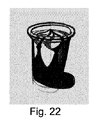
最終製品の更に他の態様を得るために、異なる製品の分量の放出段階を適宜ずらす(したがってこれらは全てが全体的に同時に放出されることはない)ことが可能である。したがって、第1の製品、その後第2の製品の放出を開始することが可能である。第1製品は、容器の底部を被覆し、一方で第2製品の放出が開始される。このように得られる最終製品の1つの代表的な態様が、図22に示される。同じ原理が当然、3つ以上の製品のコメータリングに適用可能である。 In order to obtain yet another aspect of the final product, it is possible to stagger the release steps of the different product quantities accordingly (thus not all of them being released simultaneously overall). It is therefore possible to start the release of the first product and then the second product. The first product covers the bottom of the container while the second product begins to be released. One exemplary embodiment of the final product thus obtained is shown in FIG. The same principle can of course be applied to the metering of more than two products.
製品を重複する層状に構成するために、第2製品の放出が開始するときに、第1製品の放出が停止される場合、これは更に可能である。 This is further possible if the release of the first product is stopped when the release of the second product is started in order to configure the product in overlapping layers.
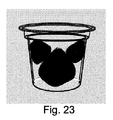
製品の一方が交互の様式で計測される一方で、他方が連続的に計測され、点の形状を有する態様が得られ得る。点の形状はまた、ノズルと容器との間の相対垂直運動により影響される。更に、第2製品はまた、その分布が、図23及び図24に示される、重複しない点を得ることを可能にする様々なダクト内において交互に分布し得る。 One of the products can be measured in an alternating fashion while the other is continuously measured, resulting in an embodiment having a point shape. The point shape is also affected by the relative vertical motion between the nozzle and the container. Furthermore, the second product can also be distributed alternately in various ducts whose distribution makes it possible to obtain non-overlapping points as shown in FIGS.
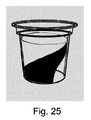
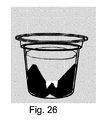
更に、1つの放出される製品の流れを段階的に低減させながら、第2の製品の流れを増加させることにより、容器内の製品の分布は、図25に示されるような角錐の形状、又は図26に示されるような二重、三重などの角錐形状を示し得る。 Furthermore, by increasing the flow of the second product while gradually reducing the flow of one discharged product, the distribution of the product in the container is a pyramid shape as shown in FIG. A pyramid shape such as double or triple as shown in FIG. 26 may be shown.
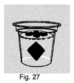
先に説明された技術の組み合わせは、図27に示される最終製品のような、魅力的な幾何学的形状を有する、複雑な態様を備える最終製品を得ることを可能にする。 The combination of the techniques described above makes it possible to obtain a final product with a complex aspect having an attractive geometry, such as the final product shown in FIG.
サーモスタットで制御したノズル、又は計量ユニットを使用することも可能である。実際、いくつかの製品は、これらの凝固点よりも高い温度において計量されるべきである。これは特に、チョコレート又はいくつかのゲルにおいて妥当する。計量ユニット及び/又はノズルはその後、凝固又は増粘した製品によるいずれかの目詰りを避けるために、有利に温度調整される。これは包装ラインが停止したときに、特に重要である。 It is also possible to use a thermostat controlled nozzle or a metering unit. In fact, some products should be weighed at temperatures above their freezing point. This is especially true in chocolate or some gels. The metering unit and / or nozzle is then advantageously temperature adjusted in order to avoid any clogging with the solidified or thickened product. This is particularly important when the packaging line is stopped.
更に、製品を実質的に均一な温度に維持するため、又は相分離を避けるため、製品を連続的に再循環させて停滞しないようにすることが可能である。この場合、循環している製品の部分のみがその後計量され、一般的に大部分を構成している別の部分は、ホッパーの方に戻される。 In addition, the product can be continuously recirculated to avoid stagnation in order to maintain the product at a substantially uniform temperature or to avoid phase separation. In this case, only the part of the product that is circulated is then weighed, and the other part, which generally constitutes the majority, is returned to the hopper.
上記により示されるように、コメータリングの良好な技能は、正確な構成及び相互作用する多くのパラメータの制御を必要とし、よって所望の結果を達成する、完全な調節を行うことは複雑であり得る。 As indicated by the above, a good skill in commuting requires precise configuration and control of many interacting parameters, and thus it can be complex to make a perfect adjustment to achieve the desired result. .
コメータリングした製品の放出を制御し、製品の落下高さを動的に調節し、必要に応じて、回転運動を適合させるため、20を超える、異なるパラメータが調節及び/又は制御される必要がある。したがって、計量機器全てが、特に製造操作者に向けた、高性能自動化及び特に正様々なパラメータのための明確な読み取りシステムを使用することが好ましい。 More than 20 different parameters need to be adjusted and / or controlled to control the release of the commuted product, dynamically adjust the drop height of the product, and adapt the rotational movement as needed. is there. Therefore, it is preferred that all weighing equipment use high-performance automation and a clear reading system, especially for a wide variety of parameters, especially for manufacturing operators.
所望の結果を得ることを可能にするパラメータのセットが保存されてもよい。このようなセットがレシピを構成する。このレシピは特に、デジタル記憶手段に保存されてもよい。レシピは、計量、又はコメータリング装置の電子制御装置によって呼び出すことができる。このようなレシピに基づき、1つ以上の関連するパラメータのバリエーションが、魅力的な視覚的態様の完全な配列を得ることを可能にする。 A set of parameters that allows to obtain the desired result may be stored. Such a set constitutes a recipe. This recipe may in particular be stored in digital storage means. The recipe can be recalled by the electronic control unit of the metering or commuting device. Based on such a recipe, one or more related parameter variations make it possible to obtain a complete array of attractive visual features.
Claims (14)
第1製品を(P1)を計量するための第1計量ユニット(41)と、
第2製品(P2)を計量するための第2計量ユニット(42)と、
前記第1計量ユニット(41)によって提供されており、第1オリフィス(11)に開いている第1ダクト(1)、及び前記第2計量ユニット(42)によって提供されており、第2オリフィス(21)に開いている第2ダクト(2)を含む、ノズル(B)と
を含む、装置において、
前記ノズル(B)は、第3オリフィスに開いている第3ダクト(3)を含んでおり、前記装置は、前記第3ダクト(3)が前記第1計量ユニット(41)及び前記第2計量ユニット(42)によって提供されるように構成されており、よって前記第1製品(P1)及び前記第2製品(P2)の混合物(M3)が、前記第3オリフィス(31)によって排出されることを特徴とする、装置。 An apparatus for co-metering liquid and / or pasty products,
A first weighing unit (41) for weighing (P1) a first product;
A second weighing unit (42) for weighing the second product (P2);
Provided by the first metering unit (41) and provided by the first duct (1) open to the first orifice (11) and the second metering unit (42), the second orifice ( 21) comprising a second duct (2) open to 21), comprising a nozzle (B),
The nozzle (B) includes a third duct (3) that is open to a third orifice, and the apparatus includes the third duct (3), the first metering unit (41) and the second metering unit. Configured to be provided by a unit (42), so that the mixture (M3) of the first product (P1) and the second product (P2) is discharged by the third orifice (31). A device characterized by.
コメータリング装置に第1製品(P1)及び第2製品(P2)を供給するステップと、
いくつかのオリフィスを含む前記コメータリング装置のノズル(B)を介して、前記第1製品を前記ノズル(B)の第1オリフィス(11)を通じて、前記第2製品を前記ノズル(B)の第2オリフィス(21)を通じて、前記第1及び第2製品の混合物(M3)を前記ノズル(B)の第3オリフィス(31)を通じて、容器内へと同時に及び/又は逐次的に放出するステップとを含む、方法。 A method for metering a liquid and / or pasty product comprising:
Supplying a first product (P1) and a second product (P2) to the metering device;
Via the nozzle (B) of the commuting device comprising several orifices, the first product passes through the first orifice (11) of the nozzle (B) and the second product passes through the nozzle (B). Simultaneously and / or sequentially discharging the mixture of the first and second products (M3) through the second orifice (21) through the third orifice (31) of the nozzle (B) into the container. Including.
ピューレ、コンポート、クーリ、又はシロップなど、主にフルーツ系の調製物;
発酵乳、フレッシュチーズ、クオーク、クリームなど、任意により風味を付けた乳製品調製物;
チョコレートプリン、バニラプリン、カラメル、チョコレートシロップ、チョコレートムース、ゼリーなど、ペースト状の調製物から選択される、請求項10〜12のいずれか一項に記載の方法。 The first product P1 and the second product P2 are different from each other.
Mainly fruit-based preparations such as puree, compote, courier or syrup;
Optionally flavored dairy preparations such as fermented milk, fresh cheese, quark, cream;
13. A method according to any one of claims 10 to 12, selected from pasty preparations such as chocolate pudding, vanilla pudding, caramel, chocolate syrup, chocolate mousse, jelly and the like.
Applications Claiming Priority (3)
| Application Number | Priority Date | Filing Date | Title |
|---|---|---|---|
| EP14152622.8 | 2014-01-27 | ||
| EP14152622 | 2014-01-27 | ||
| PCT/EP2014/077785 WO2015110226A1 (en) | 2014-01-27 | 2014-12-15 | Device and method for co-metering |
Publications (1)
| Publication Number | Publication Date |
|---|---|
| JP2017510516A true JP2017510516A (en) | 2017-04-13 |
Family
ID=49999799
Family Applications (1)
| Application Number | Title | Priority Date | Filing Date |
|---|---|---|---|
| JP2016547534A Pending JP2017510516A (en) | 2014-01-27 | 2014-12-15 | Apparatus and method for commetering |
Country Status (16)
| Country | Link |
|---|---|
| US (2) | US10299495B2 (en) |
| EP (1) | EP3099578B1 (en) |
| JP (1) | JP2017510516A (en) |
| CN (1) | CN106414244B (en) |
| AU (1) | AU2014378631B2 (en) |
| CA (1) | CA2933593C (en) |
| CL (1) | CL2016001837A1 (en) |
| ES (1) | ES2664072T3 (en) |
| HR (1) | HRP20180658T1 (en) |
| MX (1) | MX2016009239A (en) |
| MY (1) | MY179168A (en) |
| PH (1) | PH12016501314A1 (en) |
| PL (1) | PL3099578T3 (en) |
| PT (1) | PT3099578T (en) |
| RU (1) | RU2667767C2 (en) |
| WO (1) | WO2015110226A1 (en) |
Cited By (2)
| Publication number | Priority date | Publication date | Assignee | Title |
|---|---|---|---|---|
| JP2019216654A (en) * | 2018-06-19 | 2019-12-26 | 株式会社鈴乃蔵 | Process for producing jelly |
| WO2023243301A1 (en) * | 2022-06-14 | 2023-12-21 | 大和製罐株式会社 | Molded food, production method thereof and molded food packed in container |
Families Citing this family (12)
| Publication number | Priority date | Publication date | Assignee | Title |
|---|---|---|---|---|
| EP3468381B1 (en) * | 2016-06-13 | 2023-04-26 | Société des Produits Nestlé S.A. | Device, system and method for dosing a pasty food product with solid pieces and a sauce into a container |
| IT201700016823A1 (en) * | 2017-02-15 | 2018-08-15 | Gd Spa | Method and device for filling a cartridge for an aerosol generating device with a liquid. |
| US11104461B2 (en) * | 2017-09-15 | 2021-08-31 | Campbell Soup Company | Two-phase filling apparatus and methods |
| CN112188933B (en) * | 2018-06-21 | 2022-08-16 | 宝洁公司 | Integrated dispensing nozzle for co-injection of two or more liquids and method of use thereof |
| WO2019241989A1 (en) | 2018-06-22 | 2019-12-26 | The Procter & Gamble Company | Liquid filling system and method of using same |
| EP3934440A1 (en) * | 2019-03-04 | 2022-01-12 | Unilever IP Holdings B.V. | Apparatus for preparation of frozen confection products |
| RU198571U1 (en) * | 2019-10-01 | 2020-07-16 | Общество с Ограниченной Ответственностью "ФАРМПРИНТ" | Liquid dosing automation device |
| MX2022012805A (en) | 2020-04-20 | 2022-10-31 | Nestle Sa | Food product with a heterogeneous sugar distribution. |
| RU2758959C1 (en) * | 2020-11-06 | 2021-11-03 | Общество с ограниченной ответственностью "Мусихин. Мир мёда" | Method for filling food products |
| DE102020131724A1 (en) * | 2020-11-30 | 2022-06-02 | Ampack Gmbh | Dosing device, food preparation system and method for operating a dosing device |
| EP4244139A1 (en) * | 2021-01-05 | 2023-09-20 | Société des Produits Nestlé S.A. | Apparatuses and methods for enclosing a filling in a food product |
| CN117881298A (en) * | 2022-01-12 | 2024-04-12 | 广州工商学院 | Rose and Chinese yam jelly processing system based on hazard analysis and key control point system |
Citations (7)
| Publication number | Priority date | Publication date | Assignee | Title |
|---|---|---|---|---|
| JPS63187877U (en) * | 1987-05-26 | 1988-12-01 | ||
| JPH01301611A (en) * | 1988-02-02 | 1989-12-05 | Pola Chem Ind Inc | Method for filling transparent cosmetic having solid pattern and multiple filling nozzle used for the filling |
| JPH02264950A (en) * | 1989-04-06 | 1990-10-29 | Fuji Photo Film Co Ltd | Container for replenishment |
| JPH11346660A (en) * | 1998-06-12 | 1999-12-21 | Akutagawa Seika Kk | Decorated food and its production and production device |
| JP2012504945A (en) * | 2008-10-14 | 2012-03-01 | ネステク ソシエテ アノニム | Method for co-filling dairy products and co-filled composite dairy products |
| WO2013079411A1 (en) * | 2011-11-28 | 2013-06-06 | Robert Bosch Gmbh | Device for simultaneously filling at least two foods of different compositions into one container |
| WO2013083981A2 (en) * | 2011-12-06 | 2013-06-13 | Kraft Foods Global Brands Llc | Confectionery products and their manufacture |
Family Cites Families (14)
| Publication number | Priority date | Publication date | Assignee | Title |
|---|---|---|---|---|
| US3267971A (en) | 1963-07-22 | 1966-08-23 | Seymour C Graham | Packaging apparatus and process |
| SU870250A1 (en) * | 1979-09-24 | 1981-10-07 | Ждановская Кондитерская Фабрика | Metering-out device |
| US4966205A (en) * | 1988-02-02 | 1990-10-30 | Pola Chemical Industries Ltd. | Method and apparatus for charging transparent material |
| US6231902B1 (en) | 1993-03-18 | 2001-05-15 | Nestec S.A. | Mousse containing sterilized pieces of chocolate |
| FR2708563B1 (en) | 1993-08-02 | 1995-10-27 | Erca | Unit and method for dosing and distribution of liquid and / or pasty products. |
| CN2302198Y (en) * | 1995-11-10 | 1998-12-30 | 宋献诚 | Multi-function semi-fluid cool drink food filling machine |
| JP3663299B2 (en) * | 1998-06-12 | 2005-06-22 | 芥川製菓株式会社 | Decorative food production equipment |
| WO2002000029A1 (en) | 2000-06-26 | 2002-01-03 | Societe Des Produits Nestle S.A. | Fermented milk product and process |
| US7472805B2 (en) * | 2004-08-26 | 2009-01-06 | Imi Vision Limited | Beverage dispenser |
| EP1673981B1 (en) | 2004-12-21 | 2015-07-29 | Unilever PLC | Apparatus and process for preparing a frozen confection |
| IL172097A0 (en) * | 2004-12-21 | 2009-02-11 | Unilever Plc | Apparatus and process for preparing a frozen confection |
| EP2403631B1 (en) | 2009-03-06 | 2013-09-04 | Colgate-Palmolive Company | Apparatus and method for filling a container with at least two components of a composition |
| EP2639163B1 (en) * | 2012-03-15 | 2014-09-10 | Antonio Mengibar, S.A. | Method and apparatus for generating a filling pattern for filling containers |
| DK178040B1 (en) * | 2013-03-11 | 2015-04-07 | Gram Equipment As | Filling assembly and method of filling a confectionery product into a mold or container |
-
2014
- 2014-12-15 CN CN201480073750.XA patent/CN106414244B/en active Active
- 2014-12-15 AU AU2014378631A patent/AU2014378631B2/en active Active
- 2014-12-15 ES ES14811934.0T patent/ES2664072T3/en active Active
- 2014-12-15 CA CA2933593A patent/CA2933593C/en active Active
- 2014-12-15 MY MYPI2016702361A patent/MY179168A/en unknown
- 2014-12-15 EP EP14811934.0A patent/EP3099578B1/en active Active
- 2014-12-15 PL PL14811934T patent/PL3099578T3/en unknown
- 2014-12-15 PT PT148119340T patent/PT3099578T/en unknown
- 2014-12-15 US US15/114,270 patent/US10299495B2/en not_active Expired - Fee Related
- 2014-12-15 WO PCT/EP2014/077785 patent/WO2015110226A1/en active Application Filing
- 2014-12-15 RU RU2016135011A patent/RU2667767C2/en active
- 2014-12-15 JP JP2016547534A patent/JP2017510516A/en active Pending
- 2014-12-15 MX MX2016009239A patent/MX2016009239A/en unknown
-
2016
- 2016-07-01 PH PH12016501314A patent/PH12016501314A1/en unknown
- 2016-07-19 CL CL2016001837A patent/CL2016001837A1/en unknown
-
2018
- 2018-04-25 HR HRP20180658TT patent/HRP20180658T1/en unknown
-
2019
- 2019-04-12 US US16/382,821 patent/US11019833B2/en active Active
Patent Citations (8)
| Publication number | Priority date | Publication date | Assignee | Title |
|---|---|---|---|---|
| JPS63187877U (en) * | 1987-05-26 | 1988-12-01 | ||
| JPH01301611A (en) * | 1988-02-02 | 1989-12-05 | Pola Chem Ind Inc | Method for filling transparent cosmetic having solid pattern and multiple filling nozzle used for the filling |
| JPH02264950A (en) * | 1989-04-06 | 1990-10-29 | Fuji Photo Film Co Ltd | Container for replenishment |
| JPH11346660A (en) * | 1998-06-12 | 1999-12-21 | Akutagawa Seika Kk | Decorated food and its production and production device |
| JP2012504945A (en) * | 2008-10-14 | 2012-03-01 | ネステク ソシエテ アノニム | Method for co-filling dairy products and co-filled composite dairy products |
| WO2013079411A1 (en) * | 2011-11-28 | 2013-06-06 | Robert Bosch Gmbh | Device for simultaneously filling at least two foods of different compositions into one container |
| US20140326360A1 (en) * | 2011-11-28 | 2014-11-06 | Robert Bosch Gmbh | Device for simultaneously filling at least two foods of different compositions into one container |
| WO2013083981A2 (en) * | 2011-12-06 | 2013-06-13 | Kraft Foods Global Brands Llc | Confectionery products and their manufacture |
Cited By (3)
| Publication number | Priority date | Publication date | Assignee | Title |
|---|---|---|---|---|
| JP2019216654A (en) * | 2018-06-19 | 2019-12-26 | 株式会社鈴乃蔵 | Process for producing jelly |
| JP7138490B2 (en) | 2018-06-19 | 2022-09-16 | 株式会社鈴乃蔵 | Method for making jelly |
| WO2023243301A1 (en) * | 2022-06-14 | 2023-12-21 | 大和製罐株式会社 | Molded food, production method thereof and molded food packed in container |
Also Published As
| Publication number | Publication date |
|---|---|
| EP3099578A1 (en) | 2016-12-07 |
| WO2015110226A1 (en) | 2015-07-30 |
| ES2664072T3 (en) | 2018-04-18 |
| US11019833B2 (en) | 2021-06-01 |
| PT3099578T (en) | 2018-05-09 |
| RU2667767C2 (en) | 2018-09-24 |
| US20180168185A1 (en) | 2018-06-21 |
| PH12016501314B1 (en) | 2016-08-15 |
| EP3099578B1 (en) | 2018-02-28 |
| RU2016135011A3 (en) | 2018-07-17 |
| US10299495B2 (en) | 2019-05-28 |
| AU2014378631A1 (en) | 2016-07-14 |
| CN106414244A (en) | 2017-02-15 |
| CA2933593A1 (en) | 2015-07-30 |
| MX2016009239A (en) | 2016-10-03 |
| PL3099578T3 (en) | 2018-08-31 |
| CN106414244B (en) | 2019-08-20 |
| HRP20180658T1 (en) | 2018-06-01 |
| CL2016001837A1 (en) | 2017-01-20 |
| RU2016135011A (en) | 2018-03-05 |
| AU2014378631B2 (en) | 2019-10-03 |
| MY179168A (en) | 2020-10-30 |
| US20190320680A1 (en) | 2019-10-24 |
| PH12016501314A1 (en) | 2016-08-15 |
| CA2933593C (en) | 2021-01-12 |
Similar Documents
| Publication | Publication Date | Title |
|---|---|---|
| US11019833B2 (en) | Device and method for co-metering | |
| US6758056B1 (en) | Apparatus and process for molding frozen ice confectionery compositions into articles | |
| JP5134674B2 (en) | Deposition administration device | |
| EP3017702B1 (en) | Machine for making variegated ice cream or ice cream shake | |
| US6543248B2 (en) | Apparatus for molding frozen confectionery compositions into articles | |
| EP3148346B1 (en) | Apparatus and process for the manufacture of a frozen confection | |
| CA2638193C (en) | Method for producing a confectionery product | |
| CN101282654A (en) | Apparatus and method for making multiple component confectionery product | |
| EP3573470B1 (en) | Shake product blending and dispensing process | |
| US4184613A (en) | Apparatus for combining a plurality of viscous streams to form a patterned product | |
| RU2706626C2 (en) | Method for manufacturing filled and closed container, device for implementing method and container made by said method | |
| CN104126742B (en) | A kind of device for preparing the rice dumpling for being embedded with strip pattern | |
| US8757997B2 (en) | Deposited hard shell and soft chewy center candy and method of making | |
| JP2003235453A (en) | Patterned chocolate confectionary and method for producing the same, and apparatus for production thereof | |
| AU2018265195B2 (en) | Method and apparatus for preparing an edible food composition | |
| BR112016016355B1 (en) | DEVICE AND METHOD FOR CODOSING LIQUID AND/OR PASTY PRODUCTS | |
| US20180168181A1 (en) | Deposited hard shell and soft chewy center candy and method of making | |
| JP3057847U (en) | Manufacturing method and apparatus for manufacturing food products having patterned shapes | |
| WO2003097329A1 (en) | Method and apparatus for the extrusion of material |
Legal Events
| Date | Code | Title | Description |
|---|---|---|---|
| A621 | Written request for application examination |
Free format text: JAPANESE INTERMEDIATE CODE: A621 Effective date: 20171213 |
|
| A977 | Report on retrieval |
Free format text: JAPANESE INTERMEDIATE CODE: A971007 Effective date: 20181115 |
|
| A131 | Notification of reasons for refusal |
Free format text: JAPANESE INTERMEDIATE CODE: A131 Effective date: 20181120 |
|
| A601 | Written request for extension of time |
Free format text: JAPANESE INTERMEDIATE CODE: A601 Effective date: 20190220 |
|
| A601 | Written request for extension of time |
Free format text: JAPANESE INTERMEDIATE CODE: A601 Effective date: 20190422 |
|
| A521 | Request for written amendment filed |
Free format text: JAPANESE INTERMEDIATE CODE: A523 Effective date: 20190517 |
|
| A711 | Notification of change in applicant |
Free format text: JAPANESE INTERMEDIATE CODE: A712 Effective date: 20190614 |
|
| A02 | Decision of refusal |
Free format text: JAPANESE INTERMEDIATE CODE: A02 Effective date: 20191029 |