JP2017510101A - Front-end multiplexer topology for set-top boxes - Google Patents
Front-end multiplexer topology for set-top boxes Download PDFInfo
- Publication number
- JP2017510101A JP2017510101A JP2016539307A JP2016539307A JP2017510101A JP 2017510101 A JP2017510101 A JP 2017510101A JP 2016539307 A JP2016539307 A JP 2016539307A JP 2016539307 A JP2016539307 A JP 2016539307A JP 2017510101 A JP2017510101 A JP 2017510101A
- Authority
- JP
- Japan
- Prior art keywords
- subband
- signal
- filtered signal
- frequency
- diplexer
- Prior art date
- Legal status (The legal status is an assumption and is not a legal conclusion. Google has not performed a legal analysis and makes no representation as to the accuracy of the status listed.)
- Withdrawn
Links
Images


Classifications
-
- H—ELECTRICITY
- H04—ELECTRIC COMMUNICATION TECHNIQUE
- H04N—PICTORIAL COMMUNICATION, e.g. TELEVISION
- H04N7/00—Television systems
- H04N7/20—Adaptations for transmission via a GHz frequency band, e.g. via satellite
-
- H—ELECTRICITY
- H04—ELECTRIC COMMUNICATION TECHNIQUE
- H04N—PICTORIAL COMMUNICATION, e.g. TELEVISION
- H04N21/00—Selective content distribution, e.g. interactive television or video on demand [VOD]
- H04N21/40—Client devices specifically adapted for the reception of or interaction with content, e.g. set-top-box [STB]; Operations thereof
- H04N21/41—Structure of client; Structure of client peripherals
- H04N21/426—Internal components of the client ; Characteristics thereof
- H04N21/42607—Internal components of the client ; Characteristics thereof for processing the incoming bitstream
- H04N21/42615—Internal components of the client ; Characteristics thereof for processing the incoming bitstream involving specific demultiplexing arrangements
-
- H—ELECTRICITY
- H04—ELECTRIC COMMUNICATION TECHNIQUE
- H04B—TRANSMISSION
- H04B1/00—Details of transmission systems, not covered by a single one of groups H04B3/00 - H04B13/00; Details of transmission systems not characterised by the medium used for transmission
- H04B1/005—Details of transmission systems, not covered by a single one of groups H04B3/00 - H04B13/00; Details of transmission systems not characterised by the medium used for transmission adapting radio receivers, transmitters andtransceivers for operation on two or more bands, i.e. frequency ranges
- H04B1/0053—Details of transmission systems, not covered by a single one of groups H04B3/00 - H04B13/00; Details of transmission systems not characterised by the medium used for transmission adapting radio receivers, transmitters andtransceivers for operation on two or more bands, i.e. frequency ranges with common antenna for more than one band
- H04B1/0057—Details of transmission systems, not covered by a single one of groups H04B3/00 - H04B13/00; Details of transmission systems not characterised by the medium used for transmission adapting radio receivers, transmitters andtransceivers for operation on two or more bands, i.e. frequency ranges with common antenna for more than one band using diplexing or multiplexing filters for selecting the desired band
-
- H—ELECTRICITY
- H04—ELECTRIC COMMUNICATION TECHNIQUE
- H04L—TRANSMISSION OF DIGITAL INFORMATION, e.g. TELEGRAPHIC COMMUNICATION
- H04L12/00—Data switching networks
- H04L12/28—Data switching networks characterised by path configuration, e.g. LAN [Local Area Networks] or WAN [Wide Area Networks]
- H04L12/2803—Home automation networks
- H04L12/2838—Distribution of signals within a home automation network, e.g. involving splitting/multiplexing signals to/from different paths
-
- H—ELECTRICITY
- H04—ELECTRIC COMMUNICATION TECHNIQUE
- H04N—PICTORIAL COMMUNICATION, e.g. TELEVISION
- H04N21/00—Selective content distribution, e.g. interactive television or video on demand [VOD]
- H04N21/40—Client devices specifically adapted for the reception of or interaction with content, e.g. set-top-box [STB]; Operations thereof
- H04N21/41—Structure of client; Structure of client peripherals
- H04N21/426—Internal components of the client ; Characteristics thereof
Abstract
衛星信号を処理する装置及び方法が提供される。スイッチ(116)は、少なくとも2つの周波数サブバンドを含む所定の周波数範囲を有する入力信号を受信する。第1のダイプレクサ(110)はスイッチの第1の出力部へ接続され、第1及び第2の周波数サブバンドを含む第1のフィルタ処理された信号と、第3の周波数サブバンドを含む第2のフィルタ処理された信号とを生成する。第2のダイプレクサ(104)はスイッチの第2の出力部へ接続され、第1の周波数サブバンドを含む第3のフィルタ処理された信号と、第2の周波数サブバンドを含む第4のフィルタ処理された信号とを生成する。コントローラ(602)は、第1及び第2のモードの間で動作するようスイッチを作動させる。第1のモードで、スイッチは、第1及び第2のフィルタ処理された信号を生成するよう入力信号を第1のダイプレクサへ供給し、第1のダイプレクサは、第1のフィルタ処理された信号から第3及び第4のフィルタ処理された信号を生成するよう第1のフィルタ処理された信号を第2のダイプレクサへ供給する。第2のフィルタ処理された信号は、それから第1のタイプのデータを導出するようコントローラへ供給され、第3及び第4のフィルタ処理された信号は、それらから第2の異なるタイプのデータを導出するよう前記コントローラへ供給される。第2のモードで、スイッチは、入力信号から第3及び第4のフィルタ処理された信号を生成するよう入力信号を第2のダイプレクサへ供給し、第2のダイプレクサは、第3及び第4のフィルタ処理された信号をコントローラへ供給してそれらから第2の異なるタイプのデータが導出されるようにする。An apparatus and method for processing satellite signals is provided. The switch (116) receives an input signal having a predetermined frequency range including at least two frequency subbands. A first diplexer (110) is connected to the first output of the switch and has a first filtered signal including first and second frequency subbands and a second including a third frequency subband. Of the filtered signal. A second diplexer (104) is connected to the second output of the switch, and a third filtered signal including the first frequency subband and a fourth filtering process including the second frequency subband. Generated signal. The controller (602) activates the switch to operate between the first and second modes. In the first mode, the switch provides an input signal to the first diplexer to generate first and second filtered signals, and the first diplexer extracts the first filtered signal from the first filtered signal. A first filtered signal is provided to a second diplexer to generate third and fourth filtered signals. The second filtered signal is then fed to the controller to derive a first type of data, and the third and fourth filtered signals derive a second different type of data therefrom. To the controller. In the second mode, the switch provides an input signal to the second diplexer to generate third and fourth filtered signals from the input signal, and the second diplexer The filtered signals are supplied to the controller so that a second different type of data is derived therefrom.
Description
本発明は、衛星信号処理するセットトップボックスに関係があり、特に、衛星信号を受信する入力でのリターンロス及び選択性の両方を改善する新規のフロントエンドに関係がある。 The present invention relates to set-top boxes for satellite signal processing, and in particular to a new front end that improves both return loss and selectivity at the input receiving satellite signals.
衛星プロバイダから信号を受信するセットトップボックス(STB;Set-Top Box)は、当該技術でよく知られている。そのようなSTBは、2つの異なる種類の信号を処理するよう求められる。第1のタイプの信号は、衛星テレビジョンデータ(例えば、レガシー信号)を含む周波数バンドを有する。第2のタイプの信号は、ネットワーキングデータのためにリザーブされている衛星信号バンドの部分を有し、衛星信号は単線マルチスイッチ(SWM;Single Wire-Multiswitch)信号に変換される。通常、ネットワーキングデータのためにリザーブされるバンドは、マルチメディア・オーバー・コアックス・アライアンス(MoCA;Multimedia over Coax Alliance)標準に従って構造化される。MoCAバンドにおけるデータは、STBによって送受信されるインターネットデータと、特定の場所にある複数のSTBが互いと通信することができるようにするローカルエリアネットワーキングデータとを通常は含む。よって、STBの設計者は、両方のタイプの信号を受信し処理することができるSTBアーキテクチャを提供しなければならない。レガシー信号及びSWM信号の両方を処理することができる、例となるSTBは、図1において示されている。 Set-top boxes (STBs) that receive signals from satellite providers are well known in the art. Such STBs are required to process two different types of signals. The first type of signal has a frequency band that includes satellite television data (eg, legacy signals). The second type of signal has a portion of the satellite signal band that is reserved for networking data, and the satellite signal is converted to a single wire-multiswitch (SWM) signal. Typically, the bands reserved for networking data are structured according to the Multimedia over Coax Alliance (MoCA) standard. Data in the MoCA band typically includes Internet data transmitted and received by the STB and local area networking data that allows multiple STBs at a particular location to communicate with each other. Thus, STB designers must provide an STB architecture that can receive and process both types of signals. An exemplary STB that can process both legacy and SWM signals is shown in FIG.
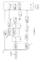
図1は、従来のSTB1のブロック図である。STB1は、STB1の完全な動作を制御するコントローラ30を有する。STB1は、衛星受信器屋外ユニット(LNB又はSWMユニット。図示せず。)からRF入力信号2を受信するFコネクタ4を有する。衛星信号が受信されて、入力信号2を生成するよう処理される方法は、よく知られており、本発明と密接な関係にない。STB1は、2.3MHz FSKトランシーバであるSWM回路7を更に有する。SWM回路7は、衛星トランスポンダをSWMチャネルへ移すために、屋外のSWMユニットへコマンドを送る。加えて、SWM回路7はまた、屋外ユニットのステータス/応答を受け、その情報をコントローラ30へ提供してよい。Fコネクタ4を介して受信される入力信号2は、フルスペクトル信号であり、レガシー信号については22kHzから2150MHzの、又はSWM信号については2.3MHzから2150MHzの範囲に及ぶ。フルスペクトル入力信号2は第1のダイプレクサ6へ供給される。第1のダイプレクサ6は、950MHzよりも大きい信号の部分が通過することができるよう信号を減衰させる第1のハイパスフィルタ(HPF;High Pass Filter)8を有する。第1のダイプレクサ6は、816MHzを下回る信号の部分が通過することができるよう信号を減衰させる第1のローパスフィルタ(LPF;Low Pass Filter)9を更に有する。第1のLPF9によってフィルタ処理される信号2の部分は、一般に、統合デジタル放送−衛星サービス(ISDB−T;Integrated Services Digital Broadcasting-Terrestrial)標準に従ってフォーマットされたデジタルテレビジョンデータを含む。LPF9によってフィルタ処理される信号の部分は、好ましくない信号である88から108MHzのFM放送バンドを更に含む。略174MHzのカットオフ周波数を有するHPF13は、第1のLPF9の出力部へ接続されており、LPF9によってフィルタ処理された信号2の部分を受信する。HPF13は、FMバンド、SWMトーン又はDisEqCトーンを除去する。レガシーモードにおいて、22kHzのDisEqC信号は、LNBのような屋外ユニット、又は屋外アンテナスイッチへコマンドを送るために使用される。SWMモードにおいて、2.3MHzのFSK信号は、衛星アンテナから来る衛星トランスポンダへSWMチャネルを割り当てるよう、屋外のSWMモジュールと通信するために使用され、この信号は、上記のSWM回路7によって処理される。ISDB−Tデータは、そのチューニングのためにISDB−Tチューナ10へ供給される。チューニングされた信号は、復調のためにISDB−T復調器11へ供給される。復調された信号はコントローラ30へ供給される。コントローラ30は、当該技術で知られている更なる処理を実行し、復調されたISDB−T信号を夫々の出力部34へ送る。信号出力部34は、ここでは単に例として示されており、STB設計の技術でよく知られているように、STB1は、STB1を表示スクリーン又はモニタへ接続する複数の異なる出力コネクタを有してよい。出力部は、制限なしに、HDMI(登録商標)ポート、コンポジットビデオポート、コンポーネント・ビデオポート、DVIポート、VGAポート、及び同軸出力ポートを含んでよい。
FIG. 1 is a block diagram of a
950MHzよりも大きい周波数を有する信号の部分は、第1のHPF8によってフィルタ処理され、第1のスイッチ12へ更に供給される。第1のスイッチ12は、HPF8によってフィルタ処理された信号の部分によってとられる経路を画定するよう選択的に制御可能な単極双投スイッチであってよい。コントローラ30は、そのセットアップ時に、レガシー信号又はSWM信号のいずれか一方を受信し処理するよう予めプログラムされる。STB1によって処理されるべき信号がレガシー信号であるとコントローラ30が決定する場合には、第1のスイッチ12は、第1のHPF8によってフィルタ処理された信号を第2のスイッチ22へ送るよう構成される。第2のスイッチ22は、フィルタ処理された衛星信号を、そのチューニングのためにレガシーチューナ(ネットワークチューナとも呼ばれる。)24へ供給する。フィルタ処理された衛星信号は、レガシーチューナ24によって分割され、1つの信号はコントローラ30のレガシー復調器25へ供給され、一方、他の出力は、コントローラ30のA3チューナ及び復調器29によって受信される前に、増幅器26によって増幅され、バラン28を通される。レガシー復調器25並びにA3チューナ及び復調器29のうちの少なくとも1つは、当該技術で知られるように表示デバイスでの表示のために、信号を夫々の出力部34へ供給する。
The portion of the signal having a frequency greater than 950 MHz is filtered by the first HPF 8 and further supplied to the
Fコネクタ4で受信される信号がSWM信号であるとコントローラ30が決定すると、第1のスイッチ12は、第1のHPF8によってフィルタ処理された信号の部分が第2のダイプレクサ14へ供給されることを可能にするよう構成される。第2のダイプレクサ14は、略1250MHzを下回る信号の部分にフィルタをかける第2のHPF18と、略1050MHzを上回る信号の部分にフィルタをかける第2のLPF16とを有する。第2のLPF16の出力は、略950MHzから1050MHzの間の範囲に及ぶ周波数バンドを有する信号である。この周波数バンドでのデータは、MoCAデータを表し、MoCAトランシーバ20を介してコントローラ30のMoCAモジュール21へ供給される。MoCAデータが処理される方法は、よく知られており、更に論じられる必要はない。
When the
第2のダイプレクサ14の第2のHPF18の出力は、衛星データを表す、略1250MHzから2150MHzの間の範囲に及ぶ周波数バンドを有する信号である。第2のHPF18によって出力された信号は、第2のスイッチ22へ供給され、レガシーチューナ24へ出力される。この信号は、上述されたのと同様に処理され、繰り返される必要はない。
The output of the
よって、レガシー信号及びSWM信号の両方を処理することができるSTBを有するために、従来のSTB1は、図2においてより詳細に示されるようなデュアルダイプレクサアーキテクチャを有する。図2は、図1において上述されたデュアルダイプレクサアーキテクチャのより詳細な図である。図2において、第1のダイプレクサ6は、略806MHzを下回る周波数を有する第1のフィルタ処理された信号と、略950MHzから2150MHzの間の範囲に及ぶ周波数バンドを有する第2のフィルタ処理された信号とを供給するよう、Fコネクタ4で接続される。第1のフィルタ処理された信号は、ISDB−Tフォーマットのデジタルテレビジョンデータを含み、一方、第2のフィルタ処理された信号は、入力信号2がレガシー信号である場合には衛星データを含み、あるいは、入力信号2がSWM信号である場合にはMoCA及び衛星データを含む。第1のダイプレクサ6によってフィルタ処理された信号がレガシー信号である場合には、950MHzよりも大きい信号の全スペクトルは、上述されたようにチューナへ供給される。対照的に、第1のダイプレクサ6によってフィルタ処理された信号がSWM信号である場合には、フィルタ処理された信号は、MoCAデータを含む周波数バンドのみを含む出力信号と、チューニングのために衛星テレビジョンデータを含む周波数バンドを含む更なる出力信号とを生成するよう、更なるフィルタリングのために第2のダイプレクサ14へ供給される。
Thus, in order to have an STB that can process both legacy and SWM signals, the
図1及び2で示されている従来のSTB設計に付随する欠点は、MoCA信号及び衛星信号を生成するはずである第2のダイプレクサ14は設計するのが難しいことである。これは、小さなトランジェントバンドが存在するためである。最適に有効であるよう、第2のダイプレクサ14は、略1050MHzで100から200MHz周波数バンド内の略50dBのMoCA除去を必要とする。除去要件に付随する制約及びスイッチに固有の制約を考慮して、許容可能な程度のリターンロスを得ることは難しい。リターンロスは、伝送線路上の電力の反射により生じる信号電力の損失である。STBがそれに適用された電力をルーティングすることができない場合には、それは反射されてFコネクタに戻り、ホームネットワーク上で接続されている他のSTBへ出力され得る。よって、2つのダイプレクサを含む従来のSTB設計は、次善レベルのリターンロスをもたらす。そのため、システム内のリターンロスの量を改善しながら、レガシーモード及びSWMモードの両方において動作することができるSTBを提供する必要性が存在する。本原理に従うシステムは、それら及び他の従来技術のシステムに付随する欠点を改善する。
A disadvantage associated with the conventional STB design shown in FIGS. 1 and 2 is that the
一実施形態において、衛星信号を処理する装置が提供される。スイッチは、所定の周波数範囲を有する入力信号を受信する。前記所定の周波数範囲は少なくとも2つの周波数サブバンドを含む。第1のダイプレクサは、前記スイッチの第1の出力部へ接続され、第1の周波数サブバンド及び第2の周波数サブバンドを含む第1のフィルタ処理された信号と、第3の周波数サブバンドを含む第2のフィルタ処理された信号とを生成する。第2のダイプレクサは、前記スイッチの第2の出力部へ接続され、前記第1の周波数サブバンドを含む第3のフィルタ処理された信号と、前記第2の周波数サブバンドを含む第4のフィルタ処理された信号とを生成する。コントローラは、第1のモードと第2のモードとの間で動作するよう前記スイッチを作動させる。前記第1のモードにおいて、前記スイッチは、前記第1のフィルタ処理された信号及び前記第2のフィルタ処理された信号を生成するよう、前記入力信号を前記第1のダイプレクサへ供給し、該第1のダイプレクサは、前記第1のフィルタ処理された信号から前記第3のフィルタ処理された信号及び前記第4のフィルタ処理された信号を生成するよう、前記第1のフィルタ処理された信号を前記第2のダイプレクサへ供給し、前記第2のフィルタ処理された信号は、それから第1のタイプのデータを導出するよう前記コントローラへ供給され、前記第3のフィルタ処理された信号及び前記第4のフィルタ処理された信号は、それらから第2の異なるタイプのデータを導出するよう前記コントローラへ供給される。前記第2のモードにおいて、前記スイッチは、前記入力信号から前記第3のフィルタ処理された信号及び前記第4のフィルタ処理された信号を生成するよう、前記入力信号を前記第2のダイプレクサへ供給し、前記第2のダイプレクサは、前記第3のフィルタ処理された信号及び前記第4のフィルタ処理された信号を前記コントローラへ供給してそれらから前記第2の異なるタイプのデータが導出されるようにする。 In one embodiment, an apparatus for processing satellite signals is provided. The switch receives an input signal having a predetermined frequency range. The predetermined frequency range includes at least two frequency subbands. A first diplexer is connected to the first output of the switch, and includes a first filtered signal including a first frequency subband and a second frequency subband, and a third frequency subband. A second filtered signal is generated. A second diplexer is connected to the second output of the switch, and a third filtered signal including the first frequency subband and a fourth filter including the second frequency subband. And generate a processed signal. The controller activates the switch to operate between the first mode and the second mode. In the first mode, the switch provides the input signal to the first diplexer to generate the first filtered signal and the second filtered signal, and the second mode A first diplexer that generates the third filtered signal and the fourth filtered signal from the first filtered signal to generate the first filtered signal; A second diplexer is provided, and the second filtered signal is provided to the controller to derive a first type of data therefrom, the third filtered signal and the fourth filtered signal. The filtered signals are supplied to the controller to derive a second different type of data therefrom. In the second mode, the switch provides the input signal to the second diplexer to generate the third filtered signal and the fourth filtered signal from the input signal. And the second diplexer supplies the third filtered signal and the fourth filtered signal to the controller, from which the second different type of data is derived. To.
他の実施形態において、衛星信号を処理する方法が提供される。当該方法は、スイッチにおいて、少なくとも2つの周波数サブバンドを含む所定の周波数範囲を有する入力信号を受信するステップと、第1のモードと第2のモードとの間で動作するようコントローラによって前記スイッチを作動させるステップとを有する。前記第1のモードで動作するよう前記スイッチを作動させることに応答して、第1のダイプレクサが前記スイッチの第1の出力部へ接続され、前記入力信号が前記第1のダイプレクサへ供給される。第1のフィルタ処理された信号が生成され、該第1のフィルタ処理された信号は、第1の周波数サブバンド及び第2の周波数サブバンドを含む。第2のフィルタ処理された信号が生成され、該第2のフィルタ処理された信号は、第3の周波数サブバンドを含む。前記第1のフィルタ処理された信号は第2のダイプレクサへ供給され、該第2のダイプレクサは、前記第1の周波数サブバンドを含む第3のフィルタ処理された信号と、前記第2の周波数サブバンドを含む第4のフィルタ処理された信号とを生成する。前記第3のフィルタ処理された信号及び前記第4のフィルタ処理された信号は、前記第1のフィルタ処理された信号に基づき生成される。前記第2のモードで動作するよう前記スイッチを作動させることに応答して、前記スイッチの第2の出力部は前記第2のダイプレクサへ接続され、前記入力信号は、前記第2のダイプレクサへ供給される。前記第2のダイプレクサは、前記入力信号に基づき、前記第1の周波数サブバンドを含む前記第3のフィルタ処理された信号と、前記第2の周波数サブバンドを含む前記第4のフィルタ処理された信号とを生成する。前記第1のダイプレクサからの前記第2のフィルタ処理された信号は、第1のタイプのデータを導出するよう、前記コントローラへ供給される。前記第3のフィルタ処理された信号及び前記第4のフィルタ処理された信号は、第2の異なるタイプのデータを導出するよう、前記第2のダイプレクサから前記コントローラへ供給される。 In another embodiment, a method for processing satellite signals is provided. The method includes receiving, at a switch, an input signal having a predetermined frequency range including at least two frequency subbands, and causing the switch to operate between a first mode and a second mode. Actuating. In response to actuating the switch to operate in the first mode, a first diplexer is connected to a first output of the switch and the input signal is provided to the first diplexer. . A first filtered signal is generated, and the first filtered signal includes a first frequency subband and a second frequency subband. A second filtered signal is generated, and the second filtered signal includes a third frequency subband. The first filtered signal is provided to a second diplexer that includes a third filtered signal including the first frequency subband and the second frequency subband. A fourth filtered signal including a band is generated. The third filtered signal and the fourth filtered signal are generated based on the first filtered signal. In response to activating the switch to operate in the second mode, a second output of the switch is connected to the second diplexer and the input signal is supplied to the second diplexer. Is done. The second diplexer is based on the input signal, the third filtered signal including the first frequency subband, and the fourth filtered signal including the second frequency subband. Signal. The second filtered signal from the first diplexer is provided to the controller to derive a first type of data. The third filtered signal and the fourth filtered signal are provided from the second diplexer to the controller to derive a second different type of data.
図示されている要素は、ハードウェア、ソフトウェア、又はそれらの組み合わせの様々な形態において実装されてよいことが理解されるべきである。望ましくは、それらの要素は、1つ以上の適切にプログラムされた汎用デバイスにおいてハードウェア及びソフトウェアを組み合わせて実装される。そのようなデバイスは、プロセッサ、メモリ、及び入出力インターフェイスを含んでよい。 It should be understood that the illustrated elements may be implemented in various forms of hardware, software, or a combination thereof. Desirably, the elements are implemented in a combination of hardware and software in one or more appropriately programmed general purpose devices. Such a device may include a processor, a memory, and an input / output interface.
本明細書は、本開示の原理を説明する。よって、明らかなように、当業者であれば、ここで明示的に記載又は図示されていなくても、本開示の原理を具現し且つその主旨及び適用範囲内に含まれる様々な配置を想到可能である。 This specification illustrates the principles of the present disclosure. Thus, as will be apparent, those skilled in the art can devise various arrangements that embody the principles of the present disclosure and fall within the spirit and scope of the present disclosure, even if not explicitly described or illustrated herein. It is.
ここで挙げられている全ての例及び条件付き言語は、当該技術を促進することに本発明者によって寄与される概念及び本開示の原理を読者が理解するのを助ける教育上の目的を意図され、そのような具体的に挙げられている例及び条件に制限されないと解釈されるべきである。 All examples and conditional languages listed herein are intended for educational purposes to help the reader understand the concepts contributed by the inventor and the principles of this disclosure to promote the technology. And should not be construed as limited to such specifically recited examples and conditions.
更に、本開示の原理、態様、及び実施形態、並びにそれらの具体例をここで挙げている全ての記述は、その構造上の同等物及び機能上の同等物の両方を包含するよう意図される。加えて、そのような同等物は、現在知られている同等物に加えて、将来開発される同等物、すなわち、構造にかかわらず同じ機能を実装するよう開発されたあらゆる要素、の両方を含むことが意図される。 Furthermore, all statements herein reciting principles, aspects, and embodiments of the disclosure, and specific examples thereof, are intended to encompass both structural and functional equivalents thereof. . In addition, such equivalents include both equivalents that will be developed in the future, in addition to currently known equivalents, i.e. any element developed to implement the same function regardless of structure. Is intended.
よって、例えば、当業者に明らかなように、ここで提示されるブロック図は、本開示の原理を具現する実例となる回路構成の概念図を表す。同様に、明らかなように、如何なるフローチャート、フロー図、状態遷移図、擬似コード、及び同様のものも、コンピュータ可読媒体において実質的に表現され、故にコンピュータ又はプロセッサによって、そのようなコンピュータ又はプロセッサが明示的に示されていようがいまいが、実行され得る様々なプロセスを表す。 Thus, for example, as will be apparent to those skilled in the art, the block diagrams presented herein represent conceptual diagrams of illustrative circuit configurations that embody the principles of the present disclosure. Similarly, as will be appreciated, any flowchart, flow diagram, state transition diagram, pseudocode, and the like is substantially represented in a computer-readable medium, and thus by a computer or processor, such a computer or processor Represents the various processes that can be executed, whether explicitly indicated.
図示されている様々な要素の機能は、専用のハードウェア、及び、適切なソフトウェアに関連してソフトウェアを実行することが可能なハードウェア、の使用を通じて提供されてよい。プロセッサによって提供される場合に、機能は、単一の専用プロセッサによって、単一の共有プロセッサによって、又は、一部が共有され得る複数の個別プロセッサによって、提供されてよい。更に、語「プロセッサ」又は「コントローラ」の明示的な使用は、ソフトウェアを実行することが可能なハードウェアにもっぱら言及すると解釈されるべきではなく、制限なしに、デジタル信号プロセッサ(“DSP”)ハードウェア、ソフトウェアを格納するリードオンリーメモリ(“ROM”)、ランダムアクセスメモリ(“RAM”)、及び不揮発性ストレージを暗に含んでよい。 The functionality of the various elements shown may be provided through the use of dedicated hardware and hardware capable of executing software in conjunction with appropriate software. When provided by a processor, functionality may be provided by a single dedicated processor, by a single shared processor, or by multiple individual processors, some of which may be shared. Furthermore, the explicit use of the word “processor” or “controller” should not be construed to refer exclusively to hardware capable of executing software, without limitation, a digital signal processor (“DSP”). Hardware, read only memory ("ROM") for storing software, random access memory ("RAM"), and non-volatile storage may be implicitly included.
ここで使用される場合に、語「コンポーネント」及び/又は「モジュール」は、ハードウェア、又はハードウェア及び実行中のソフトウェアの組み合わせ、に言及するよう意図される。例えば、コンポーネントは、制限なしに、プロセッサで実行されるプロセス、プロセッサ、オブジェクト、実行ファイル、及び/又はマイクロチップ、並びに同様のものであることができる。実例として、プロセッサで実行されるアプリケーション及びプロセッサは、いずれもコンポーネントであることができる。1つ以上のコンポーネントがプロセス内に存在することができ、コンポーネントは1つのシステムにおいてローカライズされ及び/又は2つ以上のシステムの間で分配され得る。図示される様々なコンポーネントの機能は、専用のハードウェア、及び、適切なソフトウェアに関連してソフトウェアを実行することが可能なハードウェア、の使用を通じて提供され得る。 As used herein, the terms “component” and / or “module” are intended to refer to hardware, or a combination of hardware and running software. For example, a component can be, without limitation, a process running on a processor, a processor, an object, an executable, and / or a microchip, and the like. By way of illustration, both an application running on a processor and the processor can be a component. One or more components can be present in the process, and the components can be localized in one system and / or distributed between two or more systems. The functionality of the various components shown can be provided through the use of dedicated hardware and hardware capable of executing software in conjunction with appropriate software.
従来及び/又はカスタムの他のハードウェアも含まれてよい。同様に、図示されている如何なるスイッチも、単に概念的である。それらの機能は、プログラムロジックの動作を通じて、専用のロジックを通じて、プログラム制御及び専用のロジックのインタラクションを通じて、又は手動によってさえ実行されてよい。特定の技術は、文脈からより具体的に理解されるように実施者によって選択可能である。 Other hardware, conventional and / or custom, may also be included. Similarly, any switches shown are merely conceptual. These functions may be performed through the operation of program logic, through dedicated logic, through program control and dedicated logic interaction, or even manually. The particular technique can be selected by the practitioner as will be more specifically understood from the context.
本願の特許請求の範囲において、特定の機能を実施する手段として表されている如何なる要素も、例えば、a)その機能を実施する回路素子の組み合わせ、又はb)あらゆる形をとり、従って、ファームウェア、マイクロコード又は同様ものを含むソフトウェアであって、機能を実施するよう当該ソフトウェアを実行する適切な回路構成と組み合わされるソフトウェアを含め、その機能を実施する如何なる方法も包含するよう意図される。そのような特許請求の範囲によって定義される本開示は、挙げられている様々な手段によって提供される機能が、特許請求の範囲が要求しているように組み合わされて1つにされるという事実にある。よって、そのような機能を提供することができる如何なる手段も、ここで示されているものと同等であると見なされる。これより、図面を参照して、主題が説明される。図面において、同じ参照符号は、全体を通して同じ要素を参照するために使用される。以下の記載では、説明のために、多数の具体的な詳細が、主題の完全な理解を提供するために示されている。なお、明らかなように、主題の実施形態は、それらの具体的な詳細によらずとも実施され得る。他の事例では、よく知られている構造及びデバイスは、実施形態を記載することを助けるために、ブロック図形式において示されている。 In the claims of this application, any element expressed as a means for performing a particular function may take the form of, for example, a) a combination of circuit elements performing that function, or b) any form of firmware, Software, including microcode or the like, is intended to encompass any method of performing that function, including software combined with appropriate circuitry to execute the software to perform the function. The present disclosure, as defined by such claims, provides the fact that the functions provided by the various means recited can be combined into one, as required by the claims. It is in. It is thus regarded that any means that can provide those functionalities are equivalent to those shown herein. The subject matter will now be described with reference to the drawings. In the drawings, the same reference numerals are used to refer to the same elements throughout. In the following description, for purposes of explanation, numerous specific details are set forth in order to provide a thorough understanding of the subject matter. It will be appreciated that the subject embodiments may be practiced without these specific details. In other instances, well-known structures and devices are shown in block diagram form in order to assist in describing the embodiments.
本発明は、衛星通信を介して受信された入力信号を処理する際に使用されるセットトップボックス(STB)のための新規のフロントエンドアーキテクチャを提供する。発明原理に従って、フロントエンドは、有利に、STBのFコネクタでのリターンロスを改善しながら、STBがレガシー衛星信号及びSWM衛星信号の両方を処理することを可能にする。フロントエンドは、有利に、STBが、略174MHzから2150MHzの範囲に及ぶ周波数バンドを有するフルスペクトル入力信号を、ISDB−Tバンド、高RF MoCAバンド及び衛星チューナバンドを含む幾つかのサブバンドに分けることを可能にする。フルスペクトル信号をそれらのサブバンドに分ける場合に、サブバンド間のトランジェントバンドは極めて小さく(100MHzから200MHz程度)、設計されるように高周波サブバンド(例えば、MoCAサブバンド及び衛星サブバンド)のための除去要件を実施することが絶対不可欠である。そうでなければ、夫々のサブバンド内のデータは失われるか、あるいは、別なふうに妥協され得る。フルスペクトル入力信号からサブバンドを生成するために使用される現在のフィルタリング技術に付随する問題を最小限とするよう、装置は、有利に、バンドパス/バンドストップ・ダイプレクサを使用する。ダイプレクサは、有利に、下流に位置する従来の衛星ハイパスフィルタとともに、極めて急峻なMoCA除去を提供する。このトポロジは、STBの回路構成を簡素化し、Fコネクタでのリターンロスの程度を改善する。LPF/HPFダイプレクサしか使用しないことに付随して特定の問題がある。具体的に、FコネクタでMoCAバンド及び衛星バンドについて許容可能な程度のリターンロスを有しながら、MoCA周波数バンドの適切な除去を達成することは困難である。 The present invention provides a novel front-end architecture for a set top box (STB) used in processing input signals received via satellite communications. In accordance with the inventive principles, the front end advantageously allows the STB to process both legacy and SWM satellite signals while improving return loss at the STB F connector. The front end advantageously divides the full spectrum input signal with the STB having a frequency band ranging from approximately 174 MHz to 2150 MHz into several subbands including ISDB-T band, high RF MoCA band and satellite tuner band. Make it possible. When splitting a full spectrum signal into those subbands, the transient band between subbands is very small (about 100 MHz to 200 MHz) and because of the high frequency subbands (eg MoCA subband and satellite subband) as designed. It is absolutely essential to implement the removal requirements. Otherwise, the data in each subband can be lost or otherwise compromised. In order to minimize the problems associated with current filtering techniques used to generate subbands from full spectrum input signals, the apparatus advantageously uses a bandpass / bandstop diplexer. The diplexer advantageously provides very steep MoCA removal along with conventional satellite high pass filters located downstream. This topology simplifies the STB circuit configuration and improves the degree of return loss at the F connector. There are certain problems associated with using only LPF / HPF diplexers. Specifically, it is difficult to achieve proper removal of the MoCA frequency band while having an acceptable return loss for the MoCA band and satellite band at the F connector.
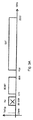
衛星STBは、MoCAデータのためにリザーブされる衛星データに割り当てられるスペクトルの部分を有するSWMモードでのMoCAデータを含まないレガシー衛星信号を処理することができる必要があるので、発明原理に従うフロントエンド装置は、有利に、特定のSTBで受信される信号のタイプに基づき、適切なフィルタリング技術を提供する。図3A及び3Bは、レガシー信号及びSWM信号の夫々のスペクトル及びサブバンドを表す。図3Aでは、レガシー信号のフルスペクトルが与えられている。レガシー信号内のデータのフルスペクトル範囲は、174MHzから2150MHzの間である。レガシー信号は、異なるタイプのデータを有する2つの別個のサブバンドを含む。第1のサブバンドはISDBTサブバンドである。ISDBTサブバンドは、174MHzから806MHzの周波数範囲を有し、ISDB−T標準に従ってフォーマットされたデジタルテレビジョンデータを提供する。第2のサブバンドは、衛星サブバンドであり、図3AではSATとラベルを付されている。衛星サブバンドは、デジタルテレビジョンデータ及びオーディオデータを含み、950から2150MHzの間の範囲に及ぶ周波数を有する。様々なタイプのデータによって占有される衛星サブバンドの部分は知られており、これ以上は論じられる必要がない。 The satellite STB needs to be able to process legacy satellite signals that do not contain MoCA data in SWM mode with a portion of the spectrum assigned to the satellite data reserved for MoCA data, so the front end in accordance with the principles of the invention The apparatus advantageously provides an appropriate filtering technique based on the type of signal received at a particular STB. 3A and 3B represent the respective spectra and subbands of the legacy signal and the SWM signal. In FIG. 3A, the full spectrum of the legacy signal is given. The full spectral range of the data in the legacy signal is between 174 MHz and 2150 MHz. Legacy signals include two separate subbands with different types of data. The first subband is the ISDBT subband. The ISDBT subband has a frequency range of 174 MHz to 806 MHz and provides digital television data formatted according to the ISDB-T standard. The second subband is a satellite subband and is labeled SAT in FIG. 3A. The satellite subband contains digital television data and audio data and has a frequency ranging between 950 and 2150 MHz. The portion of the satellite subband that is occupied by various types of data is known and need not be discussed further.
図3Bは、特定のSTBによって受信され得る入力SWM信号のフルスペクトルを表す。図3BにおけるSWM信号は3つのサブバンドを有する。第1のサブバンドは、図3Aにおける第1のサブバンドと同じであり、ISDBTフォーマットのデジタルテレビジョン信号に相当する。第1のサブバンドの周波数バンドは、174MHzから806MHzの範囲に及ぶ。第2のサブバンドは、MoCAに関連したデータを含むMoCAバンドである。第2の(MoCA)サブバンドに付随する周波数範囲は、950MHzから1050MHzの間である。SWM信号における第3のサブバンドは、衛星データサブバンドに相当し、1250MHzから2150MHzの間の範囲に及ぶ。第3のサブバンドにおけるデータは、レガシー信号の第2のサブバンドに含まれるのと同じタイプのデータを含んでよい。 FIG. 3B represents the full spectrum of the input SWM signal that can be received by a particular STB. The SWM signal in FIG. 3B has three subbands. The first subband is the same as the first subband in FIG. 3A and corresponds to a digital television signal in the ISDBT format. The frequency band of the first subband ranges from 174 MHz to 806 MHz. The second subband is a MoCA band including data related to MoCA. The frequency range associated with the second (MoCA) subband is between 950 MHz and 1050 MHz. The third subband in the SWM signal corresponds to the satellite data subband and ranges from 1250 MHz to 2150 MHz. The data in the third subband may include the same type of data that is included in the second subband of the legacy signal.
FM放送バンド88〜108MHzは不要な信号であり、ISDB−Tローパスフィルタとカスケード接続されたハイパスフィルタが、FMバンド、SWMトーン又はDisEqCトーンを除去するよう適用される。レガシーモードにおいて、22kHzのDisEqC信号は、LNBのような屋外ユニット、又は屋外のアンテナスイッチへコマンドを送るために使用される。SWMモードにおいて、2.3MHzのFSK信号は、衛星アンテナから来る衛星トランスポンダへSWMチャネルを割り当てるよう、屋外のSWMモジュールと通信するために使用される。 The FM broadcast band 88-108 MHz is an unnecessary signal, and a high-pass filter cascaded with the ISDB-T low-pass filter is applied to remove the FM band, SWM tone or DisEqC tone. In legacy mode, the 22 kHz DisEqC signal is used to send commands to an outdoor unit such as an LNB or an outdoor antenna switch. In SWM mode, the 2.3 MHz FSK signal is used to communicate with the outdoor SWM module to allocate the SWM channel to the satellite transponder coming from the satellite antenna.
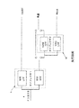
衛星STBによって処理され得る2つのタイプの入力信号の実例は、発明原理に従うフロントエンドトポロジによって解決される課題を理解することへのカギである。図3BにおけるSWM信号を参照し直すと、MoCAバンドと衛星バンドとの間には、トランジェントバンドと呼ばれる、使用されていない特定の周波数空間が存在する。それらのサブバンドをフルスペクトル信号から除去するために、様々なフィルタは、特定の用途に使用されない信号の部分を減衰させる必要がある。十分な減衰は、フィルタが意図されたように動作することを可能にするよう、望ましいサブバンドの間のトランジェントバンドが十分な長さを持つことを求める。図1及び2で論じられたような従前の繰り返しにおいて、夫々が適切な中心周波数を有するローパスフィルタ及びハイパスフィルタの組み合わせを含むダイプレクサのカスケードが使用されてきた。しかし、それらのフィルタのための周波数範囲は、許容可能な程度のリターンロスを提供しない。これは、MoCAサブバンドが通過するために、フルスペクトル入力信号の略1.1GHz部分において100MHzから200MHzの範囲内で略50dBの除去が存在すべきであるからです。これを打開するよう、発明原理に従うフロントエンドは、バンドストップフィルタ及びバンドパスフィルタから形成される第1のダイプレクサをFコネクタと第2プレクサとの間に置くようSTBのトポロジを変更する。第2のダイプレクサは、所定の中心周波数を有するハイパスフィルタと、ハイパスフィルタの中心周波数よりも低い所定の中心周波数を有するローパスフィルタとを含む。選択性及びリターンロスを改善する本発明のトポロジは、図4で表されている。装置は、Fコネクタと第1及び第2のダイプレクサの夫々との間に位置するスイッチを更に含む。よって、信号のタイプを検出することに応答して、スイッチは、出力が第2のダイプレクサへの入力として供給される第1のダイプレクサ、又は単に、原入力信号にフィルタをかける第2のダイプレクサ、のいずれか一方とFコネクタを接続するよう、選択的に制御される。 Examples of the two types of input signals that can be processed by the satellite STB are key to understanding the problem solved by the front-end topology according to the inventive principles. Referring back to the SWM signal in FIG. 3B, a specific unused frequency space called a transient band exists between the MoCA band and the satellite band. In order to remove those subbands from the full spectrum signal, various filters need to attenuate portions of the signal that are not used for a particular application. Sufficient attenuation requires that the transient band between the desired subbands be of sufficient length to allow the filter to operate as intended. In previous iterations, as discussed in FIGS. 1 and 2, a diplexer cascade has been used that includes a combination of a low pass filter and a high pass filter, each having an appropriate center frequency. However, the frequency range for these filters does not provide an acceptable return loss. This is because there should be approximately 50 dB of rejection in the range of 100 MHz to 200 MHz in the approximately 1.1 GHz portion of the full spectrum input signal in order for the MoCA subband to pass. In order to overcome this, the front end according to the principle of the invention changes the topology of the STB so that the first diplexer formed by the band stop filter and the band pass filter is placed between the F connector and the second plexer. The second diplexer includes a high-pass filter having a predetermined center frequency and a low-pass filter having a predetermined center frequency that is lower than the center frequency of the high-pass filter. The topology of the present invention that improves selectivity and return loss is represented in FIG. The apparatus further includes a switch located between the F connector and each of the first and second diplexers. Thus, in response to detecting the type of signal, the switch is either a first diplexer whose output is provided as an input to a second diplexer, or simply a second diplexer that filters the original input signal; Is selectively controlled so as to connect the F connector to either one of these.
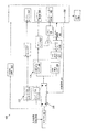
フルスペクトルSWM信号の処理の間に選択性を改善するフロントエンドトポロジを含む装置100は、図4に示されている。図4に示されているコンポーネントは、衛星信号を処理するためにSTB内に通常は含まれており、本発明の原理を説明するよう明りょうさを目的として使用される略された多数のコンポーネントを含む。発明原理に従うSTBのより詳細な説明は、図6に関連して以降で記載される。
An
入力信号はFコネクタ102を介して受信される。受信される入力信号は、第1のタイプの入力信号又は第2のタイプの入力信号であってよい。装置100は、入力信号が第1のタイプ又は第2のタイプのいずれであるのかを知るよう事前設定される。第1のタイプの入力信号は、夫々が異なるタイプのデータを含む少なくとも2つの異なるサブバンドを含み、一方、第2のタイプの入力信号は、夫々がデータを含む少なくとも3つの異なるサブバンドを含む。第1及び第2のタイプの入力信号の夫々における第1のサブバンドは、同じタイプのデータが含まれている。同様に、第1のタイプの入力信号の第2のサブバンド及び第2のタイプの入力信号の第3のサブバンドも、同じタイプのデータを含む。しかし、第2のタイプの入力信号の第2のサブバンドに含まれるデータは、第1のタイプの入力信号には存在しない。一実施形態において、第1のタイプの入力信号は、図3Aで表されているのと同様のレガシー信号であり、一方、第2のタイプの入力信号は、図3Bで表されているのと同様のSWM信号である。
The input signal is received via the
装置100は第1のダイプレクサ110を含む。第1のダイプレクサ110は、信号の所定の部分を減衰させながら信号の残り部分を如何なる減衰もなしに通すバンドストップ(BS)フィルタ112を含む。バンドストップフィルタ112の出力は、第1のフィルタ処理された信号である。第1のダイプレクサ110は、所定の周波数範囲内の信号の部分を通しながらパスバンドの外にある残り部分を減衰させるバンドパス(BP)フィルタ114を更に含む。バンドパスフィルタ114の出力は、第2のフィルタ処理された信号である。BSフィルタ112及びBPフィルタ114の夫々は、略同じ中心周波数を有する。これは、有利なことに、所定のサブバンドの十分な除去を提供しながら、他のサブバンドがBSフィルタ112を介して通されることを可能にすると同時に、除去されるバンドがBPフィルタのパスバンドであることを可能にする。一実施形態において、BSフィルタ112及びBPフィルタ114は、略1GHzの夫々の中心周波数を有し、それによって、1つの伝送経路において入力信号の部分の所定の除去を提供しながら第2の別の伝送線路における使用のために除去された部分を保つために必要とされるスペクトルを低減する。例えば、BSフィルタ112は、第2のタイプの入力信号における第2のサブバンドに対応する信号の部分を除去することによって第1のフィルタ処理された信号を生成し、更なる処理のためにより低い周波数及びより高い周波数を有する信号の部分を提供する。同時に、BPフィルタ114は、第2のサブバンドの周波数を上回る周波数及びそれを下回る周波数を有する第2のタイプの入力信号の部分を減衰させることによって第2のフィルタ処理された信号を生成する。
The
装置100は、所定のカットオフ周波数を下回る信号の部分が通ることを可能にして第3のフィルタ処理された信号を生成するローパスフィルタ(LPF)106を含む第2のダイプレクサ104を更に含む。第2のダイプレクサ104は、別のより高い所定のカットオフ周波数を上回る信号の部分が通ることを可能にして第4のフィルタ処理された信号を生成するハイパスフィルタ(HPF)108を更に含む。一実施形態において、LPF106のカットオフ周波数は806MHであって、第1のタイプの入力信号又は第2のタイプの入力信号のいずれか一方の第1のサブバンド(例えば、ISDBTサブバンド)におけるデータが通ることを可能にする。この実施形態では、HPF108のカットオフ周波数は950MHzであって、第1のタイプの入力信号の第2のサブバンド及び第2のタイプの入力信号の第3のサブバンドにおけるデータが通ることを可能にする。全ての他の事例では、LPF106及びHPF108は、信号の残り部分を減衰させる。
The
スイッチ116は、Fコネクタで受信される入力信号のタイプに応じて、Fコネクタ102を第1のダイプレクサ110又は第2のダイプレクサ104と選択的に接続する。システムコントローラ(図6に図示及び説明される。)から供給される制御信号118は、受信される信号のタイプを識別する。第1の動作モードにおいて、装置は、Fコネクタ102で第2のタイプの入力信号を受信するよう構成される。第1の動作モードでは、スイッチ116は、Fコネクタ102を第1のダイプレクサ110と接続し、更には、第1のダイプレクサ110のBSフィルタ112の出力を第2のダイプレクサ104と接続するよう構成される。この構成は、有利なことに、BSフィルタ112が第2のサブバンドに対応する第2のタイプの入力信号の部分を減衰させることを可能にし、それによって第2のフィルタ処理された信号を生成しながら、より高い周波数及びより低い周波数を有する入力信号の部分を第1のフィルタ処理された信号を第2のダイプレクサ104へ供給する。次いで、第2のダイプレクサ104は、除去されるバンドを下回るサブバンド及びそのバンドを上回るサブバンドを含む変更された第2のタイプの入力信号に相当する第1のフィルタ処理された信号を受信し、それによって、LPF106及びHPF108が、第3及び第4のフィルタ処理された信号を夫々生成するようそれらの夫々のサブバンドにフィルタをかけることを可能にする。より具体的には、LPF106は、LPF106のカットオフ周波数を上回る第2のタイプの入力信号の部分を減衰させ、ISDBTフォーマットのテレビジョンデータを表す第1のサブバンドを出力する。同時に、第2のダイプレクサ104のHPF108は、HPF108のカットオフ周波数を下回る第2のタイプの入力信号の部分を減衰させ、衛星データを表す第3のサブバンドを出力する。
The
加えて、BPフィルタ114を含むことは、有利なことに、第2のサブバンド(例えば、MoCAデータ)の周波数範囲に実質的に対応するパスバンドを定義し、全ての他の周波数を減衰させる。よって、BPフィルタ114の出力は、MoCAデータに対応する第2のタイプの入力信号の第2のサブバンドに相当する。
In addition, including a
制御信号118は、代替的に、装置100が第2の動作モードにおいて動作すべきことを示してよい。このモードでは、装置は、Fコネクタ102で第1のタイプの信号を受信するよう構成されてよい。装置が第2のモードで動作していることを示す制御信号118に応答して、スイッチ116は、Fコネクタ102を第2のダイプレクサ104と接続する。その接続時に、第2のダイプレクサ104のLPF106は、LPF106のカットオフ周波数を上回る第1のタイプの入力信号の部分を減衰させ、ISDBTフォーマットのテレビジョンデータを表す第1のサブバンド(例えば、第3のフィルタ処理された信号)を出力する。同時に、第2のダイプレクサ104のHPF108は、HPF108のカットオフ周波数を下回る第1のタイプの信号の部分を減衰させ、衛星データを表す第2のサブバンド(例えば、第4のフィルタ処理された信号)を出力する。
The control signal 118 may alternatively indicate that the
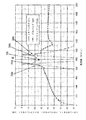
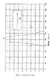
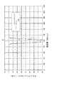
図4で記載されるトポロジは、有利なことに、図7に示されるように、Fコネクタ102での許容可能なレベルのリターンロスを有し、選択性は、図7B及び図7Cに示されるように、設計要件を十分に満足することができ、BSフィルタ112は、1.1GHz前後の入力信号の70MHz内の略60dBの除去を提供する。
The topology described in FIG. 4 advantageously has an acceptable level of return loss at the
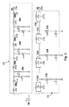
図4の第1のダイプレクサ110の例となる回路図は、図5に示されている。第1のダイプレクサ110は、バンドストップフィルタ112及びバンドパスフィルタ114を含む。バンドパスフィルタ114は、直列に配置されているインダクタ及びキャパシタから形成されている直列共振回路506a〜506dの複数の組と、並列に配置されているインダクタ及びキャパシタから形成されている並列共振回路508a〜508cの組とを含む。直列共振回路506a〜506cの夫々は、夫々の並列共振回路508a〜508cが後に続く。最後の直列共振回路506dは出力部504へ接続されている。
An exemplary circuit diagram of the
第1のダイプレクサ110のバンドストップフィルタ112は、並列に配置されているインダクタ及びキャパシタから形成されている並列共振フィルタ510a〜510dの複数の組と、直列に配置されているインダクタ及びキャパシタから形成されている直列共振フィルタ512a〜512cの組とを含む。夫々の並列共振フィルタ510a〜510cは、夫々の直列共振フィルタ512a〜512cが後に続く。並列共振フィルタ510dの出力は出力部506へ接続されている。
The
図5に示されるように、ダイプレクサは7次ダイプレクサである。なお、これは、単なる一例として記載されており、ダイプレクサは如何なる次数であってもよく、当業者であれば、入力信号の1つのサブバンドを除去するバンドストップフィルタと、その除去されるサブバンドのみが通過することができるようにするバンドパスフィルタとを有効に生成するよう如何にして直列及び並列共振フィルタのコンポーネントを設計すべきかを理解するであろう。 As shown in FIG. 5, the diplexer is a seventh order diplexer. This is described only as an example, and the diplexer may be of any order. Those skilled in the art will recognize a band stop filter that removes one subband of the input signal, and the subband to be removed. It will be understood how the components of series and parallel resonant filters should be designed to effectively generate a bandpass filter that allows only the light to pass through.
発明原理に従うフロントエンドを含む例となるSTB600は、図6で表されている。STB600は、その動作を制御するための命令を実行するコントローラ602を含む。コントローラ602は、全てのMoCA関連データを処理及びルーティングするためのMoCAモジュール604を含む。コントローラ602は、STB600によって受信されるチューニングされたデジタルテレビジョンデータを処理するためのレガシー復調器606並びにA3チューナ及び復調器608を更に含む。STB600は、第1のタイプの入力信号101a又は第2のタイプの入力信号101bの一方を選択的に受信するFコネクタ102を更に含む。STB600のコントローラ602は、第1のタイプの入力信号又は第2のタイプの入力信号の両方を処理するための命令を実行することができ、一方、コントローラ602は、第1又は第2のタイプの入力信号の一方を処理するよう事前設定される。この設定は、一般に、衛星受信器が組み込まれて、STB600がユーザの位置において設けられる場合に、実行される。STB600は、3.3MHz FSKトランシーバであるSWM回路607を更に含む。SWM回路607は、衛星トランスポンダをSWMチャネルに移すために、屋外のSWMユニットへコマンドを送る。加えて、SWM回路607は、屋外ユニットのステータス/応答を更に受信し、その情報をコントローラ602へ提供してよい。
An
STB600は、MoCAトランシーバ610、レガシーチューナ612及びISDBTチューナ618を更に含む。MoCAトランシーバ610は、第2のタイプの入力信号101bの特定のサブバンドを構成するMoCA信号を処理する。特に、MoCAサブバンドは、950MHzから1050MHzの周波数範囲によって定義される。MoCA信号は、STB600とそれに対してホームネットワーク(例えば、ホーム内で配線された同軸ケーブル)を介して接続されている他のSTBとの間のMoCAデータの送信及び受信を可能にする。MoCAトランシーバ610によって処理されたMoCAデータは、コントローラ602のMoCAモジュール604へ更に供給される。MoCAモジュール604は、MoCA標準に従う全てのアルゴリズムを含み、MoCAデータの処理を更に進める。
The
レガシーチューナ612は、950MHzから2150MHzの周波数範囲を有する第1のタイプの入力信号101aの第2のサブバンド、又は1250MHzから2150Mの周波数範囲を有する第2のタイプの入力信号101bの第3のサブバンドのいずれか一方を形成する衛星データ(例えば、ネットワーキングデータ)を処理する。レガシーチューナ612は、RF入力信号を増幅器614及びバラン616を介してA3チューナ及び復調器608へ分けるループスルー増幅器を有する。レガシー復調器606並びにA3チューナ及び復調器608は、表示又は他の処理のために、復調された衛星データを夫々の出力部603へ選択的に供給する。レガシー復調器606は、夫々の衛星TVチャネルについて、周波数、FECレート、シンボルレートのような衛星ネットワーク情報を復号し、A3チューナ及び復調器608は、衛星TVチャネルデータを復号し、データストリームを処理及び視聴出力のためにビデオデコーダへ送る。出力部603は、HDMIコンポーネント及び/又はコンポジットビデオポートを含む如何なるタイプの視聴覚出力ポートも含んでよい。出力部603は、ネットワーキングデータを出力するためのEthernet(登録商標)ポートを更に含んでよい。出力部のそれらのタイプは、単なる一例として与えられており、如何なるタイプの出力部もSTB600内に含まれてよい。
The legacy tuner 612 is a second subband of the first type of input signal 101a having a frequency range of 950 MHz to 2150 MHz, or a third sub of the second type of input signal 101b having a frequency range of 1250 MHz to 2150M. Process satellite data (eg, networking data) forming either one of the bands. Legacy tuner 612 has a loop-through amplifier that splits the RF input signal into A3 tuner and
ISDBTチューナ618は、第1の入力信号101a又は第2の入力信号101bのいずれか一方の第1のサブバンドに含まれるデータを選択的にチューニングする。第1のサブバンドは、174MHzから806MHzの間の周波数範囲を有し、ISDBTフォーマットのデジタルテレビジョンデータを含む。ISDBTチューナ618は、この周波数範囲における入力信号を受信し、ユーザによって選択された特定の周波数にチューニングする。チューニングされた信号は、ISDBTチューナ618によって復調され、コントローラ602によって夫々の出力部603へ供給される。ISDBTチューナ618より上流には、略174MHzのカットオフ周波数を有するハイパスフィルタ617がある。ハイパスフィルタ617は、FMバンド、SWMトーン又はDisEqCトーンを除去する。レガシーモードにおいて、22kHzのDisEqC信号は、LNBのような屋外ユニット、又は屋外のアンテナスイッチへコマンドを送るために使用される。SWMモードにおいて、2.3MHzのFSK信号は、衛星アンテナから来る衛星トランスポンダへSWMチャネルを割り当てるよう、屋外のSWMモジュールと通信するために使用され、個の信号は、上記のSWM回路607によって処理される。
The ISDBT tuner 618 selectively tunes data included in the first subband of either the first input signal 101a or the second input signal 101b. The first subband has a frequency range between 174 MHz and 806 MHz and includes digital television data in ISDBT format. The ISDBT tuner 618 receives input signals in this frequency range and tunes to a specific frequency selected by the user. The tuned signal is demodulated by the ISDBT tuner 618 and supplied to the respective output units 603 by the controller 602. Upstream from the ISDBT tuner 618 is a
STB600は第1のダイプレクサ110を含む。第1のダイプレクサ110は、所定の周波数バンド内のデータを除去するよう入力信号101を減衰させるとともに、更なる処理のために全ての他の周波数で入力信号のデータを通すバンドストップフィルタ112を含む。第1のダイプレクサ110は、所望のパスバンドの外にある全ての周波数で入力信号を減衰させるバンドパスフィルタ114を含む。よって、バンドパスフィルタ114は、更なる処理のために出力されるべき特定のサブバンドを入力信号から選択する。STB600は第2のダイプレクサ104を更に含む。第2のダイプレクサ104は、所定のカットオフ周波数を上回る入力信号を減衰させるローパスフィルタ106と、所定のカットオフ周波数を下回る入力信号を減衰させるハイパスフィルタ108とを含む。ローパスフィルタ106のカットオフ周波数は、ハイパスフィルタ108のカットオフ周波数よりも低い。
The
スイッチ116は、Fコネクタ102を、第1の動作モードでは第1のダイプレクサ110と、第2の動作モードでは第2のダイプレクサ104と選択的に接続する。STB600の動作モードは、Fコネクタ102で受信される入力信号のタイプに基づき決定される。第1の動作モードにおいて、STB600は、図3Bで示されるような第2のタイプの入力信号を受信するよう構成される。第2のタイプの入力信号は、MoCAデータを含む追加のサブバンドを有する。第2の動作モードにおいて、STB600は、図3Aで示されるような第1のタイプの入力信号を受信するよう構成される。第1のタイプの入力信号はレガシー信号であり、MoCAデータのサブバンドを含まない。
The
コントローラ602は、STB600が動作すべき動作のタイプを決定することに応答してスイッチ116を設定する制御信号118を発する。第1の動作モードにおいて、コントローラ602は、STB600がFコネクタ102で第2のタイプの入力信号を受信するよう構成されると決定する。第2のタイプの入力信号は、ISDBTデータに対応する、174MHzから806MHzの周波数範囲を持った第1のサブバンドと、MoCAデータに対応する、950MHzから1050MHzの周波数範囲を持った第2のサブバンドと、衛星データに対応する、1250MHzから2150MHzの周波数範囲を持った第3のサブバンドとを含む。制御信号118は、Fコネクタ102を第1のダイプレクサ110と接続するようスイッチ116を設定し、更には、バンドストップフィルタ112の出力を第2のダイプレクサ104へ接続する。第2のタイプの入力信号101bは、スイッチ116を介して第1のダイプレクサ110へ供給される。バンドストップフィルタ112は、第2のサブバンド(例えば、MoCAデータ)に対応する周波数で第2のタイプの入力信号を減衰させながら第1のサブバンド及び第3のサブバンドが第1のフィルタ処理された信号として第2のダイプレクサ104へ後述される更なるフィルタリングのために供給されることを可能にすることによって、第1のフィルタ処理された信号を生成する。
Controller 602 issues a control signal 118 that sets
第2の入力信号101bは、バンドパスフィルタ114によって更にフィルタをかけられる。バンドパスフィルタ114は、950MHzから1050MHzの間のパスバンドによって定義された周波数の外の周波数で第2のタイプの入力信号101bを減衰させることによって、第2のフィルタ処理された信号を生成する。このように、バンドパスフィルタ114によって出力される信号は、当該技術で知られている更なる処理のためにMoCAトランシーバ610へ供給されるMoCA関連データを含む第2のサブバンドに対応する。
The second input signal 101b is further filtered by a
第2のダイプレクサ104は、入力として、第1のフィルタ処理された信号を受信する。第1のフィルタ処理された信号は、第3のフィルタ処理された信号を生成するようローパスフィルタ106によって、そして、第4のフィルタ処理された信号を生成するようハイパスフィルタ108によってフィルタをかけられる。ローパスフィルタ106は、806MHzよりも大きい周波数で入力信号を減衰させ、第1のサブバンドを実質的に含む信号をISDBTチューナ618へ出力する。ISDBTチューナ618は、信号を然るべく処理し、チューニングされた信号は、コントローラ602による出力の前にISDBT復調器620によって復調される。加えて、第1のタイプの入力信号101aは、ハイパスフィルタ108によってフィルタをかけられる。ハイパスフィルタ108は、950MHzに満たない周波数で第1のタイプの入力信号を減衰させ、第2のサブバンドを実質的に含む信号を、コントローラ602によって出力される前に、レガシーチューナ612へ出力する。
The
STB600が第2のモードで動作すべきとコントローラ602が決定する場合に、制御信号118は、Fコネクタ102を第2のダイプレクサ104と接続するようスイッチ116を設定する。動作において、ISDBTデータに対応する、174MHzから806MHzの周波数を持った第1のサブバンドと、衛星データに対応する、950MHzから2150MHzの周波数範囲を持った第2のサブバンドとを有する第1のタイプの入力信号101aが、Fコネクタ102で受信される。スイッチ116は、Fコネクタ102を第2のダイプレクサ104と接続するよう設定されるので、第1のタイプの入力信号101aは、第3のフィルタ処理された信号を生成するようローパスフィルタ106によって、そして、第4のフィルタ処理された信号を生成するようハイパスフィルタ108によってフィルタをかけられる。ローパスフィルタ106は、806MHzよりも大きい周波数で入力信号を減衰させ、第1のサブバンドを実質的に含む信号をISDBTチューナ618へ出力する。ISDBTチューナ618は、信号を然るべく処理し、チューニングされた信号は、コントローラ602による出力の前にISDBT復調器620によって復調される。加えて、第1のタイプの入力信号101aは、ハイパスフィルタ108によってフィルタをかけられる。ハイパスフィルタ108は、950MHzに満たない周波数で第1のタイプの入力信号を減衰させ、第2のサブバンドを実質的に含む信号を、コントローラ602によって出力される前に、レガシーチューナ612へ出力する。
When the controller 602 determines that the
図6におけるSTB600のトポロジは、有利なことに、Fコネクタ102でのリターンロスを改善し、BSフィルタ112は、1.1GHz前後の入力信号の70MHz内での略60dBの除去を提供する。
The
図7A乃至7Dは、図4乃至6における第1のダイプレクサ110の周波数応答のグラフ表示を提供する。それらのグラフは、STB600が第1のモードにおいて動作しており、第1のダイプレクサ110を用いて、第2のダイプレクサ104によるフィルタリングより前にMoCA除去を提供する場合において、改善されたリターンロス及び選択性の視覚表現を更に提供する。702のラベルを付された線は、パスバンド周波数特性を表す。これは、図7Bにおいて明らかに示されている。一方、704のラベルを付された線は、バンドストップ周波数応答を表し、図7Cにおいて明らかに示されており、706のラベルを付された線は、所与の周波数バンドでのリターンロスを表し、図7Dにおいて明らかに示されている。線702a及び704aは、略950MHzで集まり、それによって、バンドストップの下限を設定する。線702b及び704bは、バンドストップの上限に相当する略1050MHzで集まる。第1のダイプレクサ110にこの構成を使用することによって、装置は、有利なことに、MoCAバンド950MHzから1050MHzにわたって60dBの除去を達成する。図7Aから、MoCAパスバンドの選択性は急勾配であり、1050MHzから1250MHzへの遷移は80dBに達し得ることが分かる。更には、Fコネクタでのリターンロスは、STB設計にとって課題である衛星バンドでの略35dBの大変望ましいレベルに達することができる。このことは大いに望ましい。これは、10dBよりも大きいリターンロスが優れたワイドバンド設計に相当し、ほとんどのSTBが8dB以上のリターンロス設計要件を有することが、従来より理解されているためである。図7Dは、図4乃至6のダイプレクサによって処理される入力信号の全てのサブバンドに対するこの大いに望ましいリターンロスを示す。図7Aは、図7B乃至7Dの個々のプロットを含む結合プロットである。
7A-7D provide a graphical representation of the frequency response of the
図8は、発明原理に従うSTB600によって衛星信号が処理される方法を詳述するフロー図である。ステップ802で、入力信号はスイッチ116で受信される。入力信号は所定の周波数範囲を有し、所定の周波数範囲は少なくとも2つの周波数サブバンドを含む。ステップ804で、コントローラ602は、第1のモードと第2のモードとの間で動作するようスイッチ116を作動させる。第1のモードで動作するようスイッチ116を作動させることに応答して、ステップ806で、第1のダイプレクサ110はスイッチ116の第1の出力部へ接続され、ステップ808で、入力信号は第1のダイプレクサ110へ供給される。ステップ810で、第1のフィルタ処理された信号が生成される。第1のフィルタ処理された信号は、第1の周波数サブバンド及び第2の周波数サブバンドを含む。ステップ812で、第2のフィルタ処理された信号は生成され、第3の周波数サブバンドを含む。ステップ814で、第1のフィルタ処理された信号は第2のダイプレクサ104へ供給される。第1のフィルタ処理された信号に基づき、ステップ816で、第1の周波数サブバンドを含む第3のフィルタ処理された信号及び第2の周波数サブバンドを含む第4のフィルタ処理された信号は生成される。ステップ818で、第2のフィルタ処理された信号は、第1のタイプのデータを導出するよう、第1のダイプレクサ110からコントローラ602へ供給される。ステップ820で、第3及び第4のフィルタ処理された信号は、第2の別のタイプのデータを導出するようコントローラ602へ供給される。
FIG. 8 is a flow diagram detailing how satellite signals are processed by the
ステップ804へ戻って、第2のモードで動作するようスイッチ116を作動させることに応答して、ステップ805で、スイッチ116の第2の出力部は第2のダイプレクサ104へ接続される。ステップ807で、入力信号は第2のダイプレクサ104へ供給される。ステップ809で、第1の周波数サブバンドを含む第3のフィルタ処理された信号及び第2の周波数サブバンドを含む第4のフィルタ処理された信号は、入力信号を用いて生成される。第3及び第4のフィルタ処理された信号が第2の動作モードにおいて生成されると、プロセスはステップ820で続き、これによって、第3及び第4のフィルタ処理された信号は、第2の別のタイプのデータを導出するようコントローラ602へ供給される。
Returning to step 804, in response to actuating the
ここで記載される実施は、例えば、方法若しくはプロセス、装置、又はハードウェア及びソフトウェアの組み合わせにおいて実施されてよい。たとえ単一の実施形態に関してしか論じられないとしても(例えば、方法としてしか論じられないとしても)、論じられている特徴の実施は、他の形態(例えば、ハードウェアによる装置、ハードウェア及びソフトウェアによる装置、又はコンピュータ可読媒体)においても実施されてよい。装置は、例えば、適切なハードウェア、ソフトウェア、及びファームウェアにおいて実施されてよい。方法は、例えば、プロセッサのような装置において実施されてよい。プロセッサは、如何なるプロセッシングデバイスも指し、例えば、コンピュータ、マイクロプロセッサ、集積回路、又はプログラム可能なロジックデバイスを含む。プロセッシングデバイスは、例えば、コンピュータ、携帯電話機、タブレット、ポータブル/パーソナルデジタルアシスタント(“PDA”)、及びエンドユーザ間の情報のやり取りを助ける他のデバイスのような、通信デバイスを更に含む。 The implementations described herein may be implemented, for example, in a method or process, an apparatus, or a combination of hardware and software. Even if discussed only with respect to a single embodiment (e.g., only discussed as a method), implementation of the discussed features may take other forms (e.g., hardware devices, hardware and software). Or a computer readable medium). The device may be implemented, for example, in suitable hardware, software, and firmware. The method may be implemented in an apparatus such as a processor, for example. A processor refers to any processing device, including, for example, a computer, a microprocessor, an integrated circuit, or a programmable logic device. Processing devices further include communication devices such as, for example, computers, mobile phones, tablets, portable / personal digital assistants (“PDAs”), and other devices that facilitate the exchange of information between end users.
加えて、方法は、プロセッサによって実行される命令によって実施されてよく、そのような命令は、プロセッサ、あるいは、例えば、集積回路、ソフトウェア担体又は他の記憶デバイス(例えば、ハードディスク、コンパクトディスケット、ランダムアクセスメモリ(“RAM”)、リードオンリーメモリ(“ROM”)又はあらゆる他の磁気、光、若しくは固体状態媒体)のようなコンピュータ可読媒体において記憶されてよい。命令は、上記の媒体のいずれかのようなコンピュータ可読媒体において有形に具現されるアプリケーションプログラムを形成してよい。当然に、プロセッサは、プロセッサユニットの部分として、例えば、プロセスを実行するための命令を有するコンピュータ可読媒体を含んでよい。命令は、本発明の方法に対応し、実行される場合に、汎用コンピュータを、本発明の方法を実行する特定のマシンに変えることができる。 In addition, the method may be implemented by instructions executed by a processor, such instructions being either a processor or, for example, an integrated circuit, software carrier or other storage device (eg, hard disk, compact diskette, random access). It may be stored in a computer readable medium, such as memory (“RAM”), read only memory (“ROM”) or any other magnetic, optical, or solid state medium. The instructions may form an application program that is tangibly embodied on a computer-readable medium, such as any of the media described above. Of course, the processor may include a computer readable medium having instructions for performing the process, for example, as part of the processor unit. The instructions, when executed in response to the method of the present invention, can turn a general purpose computer into a specific machine that performs the method of the present invention.
上述されたものは、実施形態の例を含む。当然、実施形態を説明する目的でコンポーネント又はメソッドロジの考えられるあらゆる組み合わせを記載することは不可能であり、当業者であれば、実施形態の更なる組み合わせ及び置換が可能であると認識することができる。然るに、主題は、添付の図面の主旨及び適用範囲内にある全てのそのような代替、改良及び変更を包含するよう意図される。更には、語「含む(includes)」が詳細な説明又は特許請求の範囲のいずれかにおいて使用される限りにおいて、そのような語は、語「有する(comprising)」が請求項において‘つなぎ語(transitional word)’として用いられる場合に解釈されるように、語「有する」と同様に包括的であるよう意図される。 What has been described above includes examples of the embodiments. Of course, it is not possible to describe every possible combination of components or method logic for the purpose of describing the embodiment, and those skilled in the art will recognize that further combinations and substitutions of the embodiment are possible. Can do. Accordingly, the subject matter is intended to embrace all such alterations, modifications and variations that fall within the spirit and scope of the accompanying drawings. Furthermore, to the extent that the word “includes” is used in either the detailed description or in the claims, such a word can be interpreted as the word “comprising” It is intended to be as inclusive as the word “having” as interpreted when used as a transitional word) ′.
上述されたものは、実施形態の例を含む。当然、実施形態を説明する目的でコンポーネント又はメソッドロジの考えられるあらゆる組み合わせを記載することは不可能であり、当業者であれば、実施形態の更なる組み合わせ及び置換が可能であると認識することができる。然るに、主題は、添付の図面の主旨及び適用範囲内にある全てのそのような代替、改良及び変更を包含するよう意図される。更には、語「含む(includes)」が詳細な説明又は特許請求の範囲のいずれかにおいて使用される限りにおいて、そのような語は、語「有する(comprising)」が請求項において‘つなぎ語(transitional word)’として用いられる場合に解釈されるように、語「有する」と同様に包括的であるよう意図される。
上記の実施形態に加えて、以下の付記を開示する。
(付記1)
衛星信号を処理する装置であって、
少なくとも2つの周波数サブバンドを含む所定の周波数範囲を有する入力信号を受信するスイッチと、
前記スイッチの第1の出力部へ接続され、第1の周波数サブバンド及び第2の周波数サブバンドを含む第1のフィルタ処理された信号と、第3の周波数サブバンドを含む第2のフィルタ処理された信号とを生成する第1のダイプレクサと、
前記スイッチの第2の出力部へ接続され、前記第1の周波数サブバンドを含む第3のフィルタ処理された信号と、前記第2の周波数サブバンドを含む第4のフィルタ処理された信号とを生成する第2のダイプレクサと、
第1のモードと第2のモードとの間で動作するよう前記スイッチを作動させるコントローラと
を有し、
前記第1のモードにおいて、前記スイッチは、前記第1のフィルタ処理された信号及び前記第2のフィルタ処理された信号を生成するよう、前記入力信号を前記第1のダイプレクサへ供給し、該第1のダイプレクサは、前記第1のフィルタ処理された信号から前記第3のフィルタ処理された信号及び前記第4のフィルタ処理された信号を生成するよう、前記第1のフィルタ処理された信号を前記第2のダイプレクサへ供給し、前記第2のフィルタ処理された信号は、それから第1のタイプのデータを導出するよう前記コントローラへ供給され、前記第3のフィルタ処理された信号及び前記第4のフィルタ処理された信号は、それらから第2の異なるタイプのデータを導出するよう前記コントローラへ供給され、
前記第2のモードにおいて、前記スイッチは、前記入力信号から前記第3のフィルタ処理された信号及び前記第4のフィルタ処理された信号を生成するよう、前記入力信号を前記第2のダイプレクサへ供給し、前記第2のダイプレクサは、前記第3のフィルタ処理された信号及び前記第4のフィルタ処理された信号を前記コントローラへ供給してそれらから前記第2の異なるタイプのデータが導出されるようにする、
装置。
(付記2)
前記第1のダイプレクサは、バンドストップフィルタ及びバンドパスフィルタを含み、
前記バンドパスフィルタのパスバンドは、前記バンドストップフィルタによって拒絶されるバンドと等しい、
付記1に記載の装置。
(付記3)
前記第2のダイプレクサは、ハイパスフィルタ及びローパスフィルタを含み、
前記ローパスフィルタのカットオフ周波数は、前記ハイパスフィルタのカットオフ周波数よりも小さい、
付記1に記載の装置。
(付記4)
前記入力信号は、レガシー衛星信号及び単線マルチスイッチ(SWM)モード信号のうちの1つを含む、
付記1に記載の装置。
(付記5)
前記レガシー衛星信号は、ISDBTデータを有する第1のサブバンドと、衛星データを有する第2のサブバンドとを含み、
前記第2のサブバンドは、前記第1のサブバンドよりも高い周波数範囲を有する、
付記4に記載の装置。
(付記6)
前記SWMモード信号は、ISDBTデータを有する第1のサブバンドと、MoCAデータを有する第2のサブバンドと、衛星データを有する第3のサブバンドとを含み、
前記第2のサブバンドは、前記第1のサブバンドの周波数範囲と前記第3のサブバンドの周波数範囲との間の周波数範囲を有する、
付記4に記載の装置。
(付記7)
衛星信号を処理する方法であって、
スイッチにおいて、少なくとも2つの周波数サブバンドを含む所定の周波数範囲を有する入力信号を受信するステップと、
第1のモードと第2のモードとの間で動作するようコントローラによって前記スイッチを作動させるステップであって、
前記第1のモードで動作するよう前記スイッチを作動させることに応答して、
第1のダイプレクサを前記スイッチの第1の出力部へ接続し、
前記入力信号を前記第1のダイプレクサへ供給し、
第1の周波数サブバンド及び第2の周波数サブバンドを含む第1のフィルタ処理された信号と、第3の周波数サブバンドを含む第2のフィルタ処理された信号とを生成し、
前記第1のフィルタ処理された信号を第2のダイプレクサへ供給し、
前記第1のフィルタ処理された信号に基づき、前記第1の周波数サブバンドを含む第3のフィルタ処理された信号と、前記第2の周波数サブバンドを含む第4のフィルタ処理された信号とを生成し、
前記第2のモードで動作するよう前記スイッチを作動させることに応答して、
前記スイッチの第2の出力部を前記第2のダイプレクサへ接続し、
前記入力信号を前記第2のダイプレクサへ供給し、
前記入力信号に基づき、前記第1の周波数サブバンドを含む前記第3のフィルタ処理された信号と、前記第2の周波数サブバンドを含む前記第4のフィルタ処理された信号とを生成し、
前記第1のダイプレクサから前記第2のフィルタ処理された信号を前記コントローラへ供給して、第1のタイプのデータを導出し、
前記第2のダイプレクサから前記第3のフィルタ処理された信号及び前記第4のフィルタ処理された信号を前記コントローラへ供給して、第2の異なるタイプのデータを導出する、前記作動させるステップと
を有する方法。
(付記8)
前記第1のモードにおける前記生成するステップは、
前記第1のフィルタ処理された信号を生成するようバンドパスフィルタを使用することと、
前記第2のフィルタ処理された信号を生成するようバンドストップフィルタを使用することと
を含み、
前記バンドパスフィルタのパスバンドは、前記バンドストップフィルタによって拒絶される周波数バンドと等しい、
付記7に記載の方法。
(付記9)
前記第2のモードにおける前記生成するステップは、
前記第3のフィルタ処理された信号を生成するようローパスフィルタを使用することと、
前記第4のフィルタ処理された信号を生成するようハイパスフィルタを使用することと
を含み、
前記ローパスフィルタのカットオフ周波数は、前記ハイパスフィルタのカットオフ周波数よりも小さい、
付記7に記載の方法。
(付記10)
前記入力信号は、レガシー衛星信号及び単線マルチスイッチ(SWM)モード信号のうちの1つを含む、
付記7に記載の方法。
(付記11)
前記レガシー衛星信号は、ISDBTデータを有する第1のサブバンドと、衛星データを有する第2のサブバンドとを含み、
前記第2のサブバンドは、前記第1のサブバンドよりも高い周波数範囲を有する、
付記10に記載の方法。
(付記12)
前記SWMモード信号は、ISDBTデータを有する第1のサブバンドと、MoCAデータを有する第2のサブバンドと、衛星データを有する第3のサブバンドとを含み、
前記第2のサブバンドは、前記第1のサブバンドの周波数範囲と前記第3のサブバンドの周波数範囲との間の周波数範囲を有する、
付記10に記載の方法。
(付記13)
衛星信号を処理する装置であって、
少なくとも2つの周波数サブバンドを含む所定の周波数範囲を有する入力信号を受信する受信手段と、
前記受信手段の第1の出力部へ接続される第1のフィルタリング手段であって、第1の周波数サブバンド及び第2の周波数サブバンドを含む第1のフィルタ処理された信号と、第3の周波数サブバンドを含む第2のフィルタ処理された信号とを生成する前記第1のフィルタリング手段と、
前記受信手段の第2の出力部へ接続される第2のフィルタリング手段であって、前記第1の周波数サブバンドを含む第3のフィルタ処理された信号と、前記第2の周波数サブバンドを含む第4のフィルタ処理された信号とを生成する前記第2のフィルタリング手段と、
第1のモードと第2のモードとの間で動作するよう前記受信手段を作動させる作動手段であって、
前記第1のモードにおいて、前記受信手段は、前記第1のフィルタ処理された信号及び前記第2のフィルタ処理された信号を生成するよう、前記入力信号を前記第1のフィルタリング手段へ供給し、該第1のフィルタリング手段は、前記第1のフィルタ処理された信号から前記第3のフィルタ処理された信号及び前記第4のフィルタ処理された信号を生成するよう、前記第1のフィルタ処理された信号を前記第2のフィルタリング手段へ供給し、
前記第2のモードにおいて、前記受信手段は、前記入力信号から前記第3のフィルタ処理された信号及び前記第4のフィルタ処理された信号を生成するよう、前記入力信号を前記第2のフィルタリング手段へ供給する、前記作動手段と、
フィルタ処理された信号を処理する処理手段であって、
前記第1のモードにおいて、前記第2のフィルタ処理された信号を受信してそれから第1のタイプのデータを導出し、前記第3のフィルタ処理された信号及び前記第4のフィルタ処理された信号を受信してそれらから第2の異なるタイプのデータを導出し、
前記第2のモードにおいて、前記入力信号に基づき生成された前記第3のフィルタ処理された信号及び前記第4のフィルタ処理された信号を受信してそれらから前記第2の異なるタイプのデータを導出する、前記処理手段と
を有する装置。
(付記14)
前記第1のフィルタリング手段は、バンドストップフィルタ及びバンドパスフィルタを含む第1のダイプレクサを有し、
前記バンドパスフィルタのパスバンドは、前記バンドストップフィルタによって拒絶されるバンドと等しい、
付記13に記載の装置。
(付記15)
前記第2のフィルタリング手段は、ハイパスフィルタ及びローパスフィルタを含む第2のダイプレクサを有し、
前記ローパスフィルタのカットオフ周波数は、前記ハイパスフィルタのカットオフ周波数よりも小さい、
付記14に記載の装置。
(付記16)
前記入力信号は、レガシー衛星信号及び単線マルチスイッチ(SWM)モード信号のうちの1つを含む、
付記13に記載の装置。
(付記17)
前記レガシー衛星信号は、ISDBTデータを有する第1のサブバンドと、衛星データを有する第2のサブバンドとを含み、
前記第2のサブバンドは、前記第1のサブバンドよりも高い周波数範囲を有する、
付記16に記載の装置。
(付記18)
前記SWMモード信号は、ISDBTデータを有する第1のサブバンドと、MoCAデータを有する第2のサブバンドと、衛星データを有する第3のサブバンドとを含み、
前記第2のサブバンドは、前記第1のサブバンドの周波数範囲と前記第3のサブバンドの周波数範囲との間の周波数範囲を有する、0
付記16に記載の装置。
What has been described above includes examples of the embodiments. Of course, it is not possible to describe every possible combination of components or method logic for the purpose of describing the embodiment, and those skilled in the art will recognize that further combinations and substitutions of the embodiment are possible. Can do. Accordingly, the subject matter is intended to embrace all such alterations, modifications and variations that fall within the spirit and scope of the accompanying drawings. Furthermore, to the extent that the word “includes” is used in either the detailed description or in the claims, such a word can be interpreted as the word “comprising” It is intended to be as inclusive as the word “having” as interpreted when used as a transitional word) ′.
In addition to the above embodiment, the following supplementary notes are disclosed.
(Appendix 1)
A device for processing satellite signals,
A switch for receiving an input signal having a predetermined frequency range including at least two frequency subbands;
A first filtered signal connected to the first output of the switch and including a first frequency subband and a second frequency subband and a second filtered process including a third frequency subband A first diplexer for generating a processed signal;
A third filtered signal connected to a second output of the switch and including the first frequency subband and a fourth filtered signal including the second frequency subband; A second diplexer to generate;
A controller that activates the switch to operate between a first mode and a second mode;
Have
In the first mode, the switch provides the input signal to the first diplexer to generate the first filtered signal and the second filtered signal, and the second mode A first diplexer that generates the third filtered signal and the fourth filtered signal from the first filtered signal to generate the first filtered signal; A second diplexer is provided, and the second filtered signal is provided to the controller to derive a first type of data therefrom, the third filtered signal and the fourth filtered signal. The filtered signals are fed to the controller to derive a second different type of data therefrom;
In the second mode, the switch provides the input signal to the second diplexer to generate the third filtered signal and the fourth filtered signal from the input signal. And the second diplexer supplies the third filtered signal and the fourth filtered signal to the controller, from which the second different type of data is derived. To
apparatus.
(Appendix 2)
The first diplexer includes a band stop filter and a band pass filter;
The passband of the bandpass filter is equal to the band rejected by the bandstop filter;
The apparatus according to
(Appendix 3)
The second diplexer includes a high pass filter and a low pass filter,
The cutoff frequency of the low-pass filter is smaller than the cutoff frequency of the high-pass filter,
The apparatus according to
(Appendix 4)
The input signal includes one of a legacy satellite signal and a single-wire multi-switch (SWM) mode signal,
The apparatus according to
(Appendix 5)
The legacy satellite signal includes a first subband having ISDBT data and a second subband having satellite data;
The second subband has a higher frequency range than the first subband;
The apparatus according to appendix 4.
(Appendix 6)
The SWM mode signal includes a first subband having ISDBT data, a second subband having MoCA data, and a third subband having satellite data;
The second subband has a frequency range between a frequency range of the first subband and a frequency range of the third subband;
The apparatus according to appendix 4.
(Appendix 7)
A method for processing satellite signals, comprising:
Receiving an input signal at a switch having a predetermined frequency range including at least two frequency subbands;
Activating the switch by a controller to operate between a first mode and a second mode, comprising:
In response to actuating the switch to operate in the first mode,
Connecting a first diplexer to the first output of the switch;
Supplying the input signal to the first diplexer;
Generating a first filtered signal including a first frequency subband and a second frequency subband, and a second filtered signal including a third frequency subband;
Providing the first filtered signal to a second diplexer;
Based on the first filtered signal, a third filtered signal including the first frequency subband and a fourth filtered signal including the second frequency subband. Generate
In response to actuating the switch to operate in the second mode,
Connecting a second output of the switch to the second diplexer;
Supplying the input signal to the second diplexer;
Generating, based on the input signal, the third filtered signal including the first frequency subband and the fourth filtered signal including the second frequency subband;
Providing the second filtered signal from the first diplexer to the controller to derive a first type of data;
Providing the third filtered signal and the fourth filtered signal from the second diplexer to the controller to derive a second different type of data;
Having a method.
(Appendix 8)
The generating step in the first mode comprises:
Using a bandpass filter to generate the first filtered signal;
Using a band stop filter to generate the second filtered signal;
Including
The passband of the bandpass filter is equal to the frequency band rejected by the bandstop filter;
The method according to appendix 7.
(Appendix 9)
The generating step in the second mode comprises:
Using a low pass filter to generate the third filtered signal;
Using a high pass filter to generate the fourth filtered signal;
Including
The cutoff frequency of the low-pass filter is smaller than the cutoff frequency of the high-pass filter,
The method according to appendix 7.
(Appendix 10)
The input signal includes one of a legacy satellite signal and a single-wire multi-switch (SWM) mode signal,
The method according to appendix 7.
(Appendix 11)
The legacy satellite signal includes a first subband having ISDBT data and a second subband having satellite data;
The second subband has a higher frequency range than the first subband;
The method according to
(Appendix 12)
The SWM mode signal includes a first subband having ISDBT data, a second subband having MoCA data, and a third subband having satellite data;
The second subband has a frequency range between a frequency range of the first subband and a frequency range of the third subband;
The method according to
(Appendix 13)
A device for processing satellite signals,
Receiving means for receiving an input signal having a predetermined frequency range including at least two frequency subbands;
A first filtering means connected to a first output of the receiving means, the first filtered signal including a first frequency subband and a second frequency subband; and a third Said first filtering means for generating a second filtered signal comprising frequency subbands;
A second filtering means connected to a second output of the receiving means, comprising a third filtered signal including the first frequency subband and the second frequency subband; Said second filtering means for generating a fourth filtered signal;
Actuating means for actuating the receiving means to operate between a first mode and a second mode,
In the first mode, the receiving means supplies the input signal to the first filtering means to generate the first filtered signal and the second filtered signal; The first filtering means is first filtered to generate the third filtered signal and the fourth filtered signal from the first filtered signal. Supplying a signal to the second filtering means;
In the second mode, the receiving means converts the input signal to the second filtering means so as to generate the third filtered signal and the fourth filtered signal from the input signal. Supplying said actuating means;
Processing means for processing the filtered signal,
In the first mode, receiving the second filtered signal and deriving a first type of data therefrom, the third filtered signal and the fourth filtered signal And deriving a second different type of data therefrom,
Receiving the third filtered signal and the fourth filtered signal generated based on the input signal in the second mode and deriving the second different type of data therefrom; And said processing means
Having a device.
(Appendix 14)
The first filtering means includes a first diplexer including a band stop filter and a band pass filter,
The passband of the bandpass filter is equal to the band rejected by the bandstop filter;
The apparatus according to
(Appendix 15)
The second filtering means has a second diplexer including a high-pass filter and a low-pass filter,
The cutoff frequency of the low-pass filter is smaller than the cutoff frequency of the high-pass filter,
The apparatus according to
(Appendix 16)
The input signal includes one of a legacy satellite signal and a single-wire multi-switch (SWM) mode signal,
The apparatus according to
(Appendix 17)
The legacy satellite signal includes a first subband having ISDBT data and a second subband having satellite data;
The second subband has a higher frequency range than the first subband;
The apparatus according to
(Appendix 18)
The SWM mode signal includes a first subband having ISDBT data, a second subband having MoCA data, and a third subband having satellite data;
The second subband has a frequency range between the frequency range of the first subband and the frequency range of the third subband, 0
The apparatus according to
Claims (18)
少なくとも2つの周波数サブバンドを含む所定の周波数範囲を有する入力信号を受信するスイッチと、
前記スイッチの第1の出力部へ接続され、第1の周波数サブバンド及び第2の周波数サブバンドを含む第1のフィルタ処理された信号と、第3の周波数サブバンドを含む第2のフィルタ処理された信号とを生成する第1のダイプレクサと、
前記スイッチの第2の出力部へ接続され、前記第1の周波数サブバンドを含む第3のフィルタ処理された信号と、前記第2の周波数サブバンドを含む第4のフィルタ処理された信号とを生成する第2のダイプレクサと、
第1のモードと第2のモードとの間で動作するよう前記スイッチを作動させるコントローラと
を有し、
前記第1のモードにおいて、前記スイッチは、前記第1のフィルタ処理された信号及び前記第2のフィルタ処理された信号を生成するよう、前記入力信号を前記第1のダイプレクサへ供給し、該第1のダイプレクサは、前記第1のフィルタ処理された信号から前記第3のフィルタ処理された信号及び前記第4のフィルタ処理された信号を生成するよう、前記第1のフィルタ処理された信号を前記第2のダイプレクサへ供給し、前記第2のフィルタ処理された信号は、それから第1のタイプのデータを導出するよう前記コントローラへ供給され、前記第3のフィルタ処理された信号及び前記第4のフィルタ処理された信号は、それらから第2の異なるタイプのデータを導出するよう前記コントローラへ供給され、
前記第2のモードにおいて、前記スイッチは、前記入力信号から前記第3のフィルタ処理された信号及び前記第4のフィルタ処理された信号を生成するよう、前記入力信号を前記第2のダイプレクサへ供給し、前記第2のダイプレクサは、前記第3のフィルタ処理された信号及び前記第4のフィルタ処理された信号を前記コントローラへ供給してそれらから前記第2の異なるタイプのデータが導出されるようにする、
装置。 A device for processing satellite signals,
A switch for receiving an input signal having a predetermined frequency range including at least two frequency subbands;
A first filtered signal connected to the first output of the switch and including a first frequency subband and a second frequency subband and a second filtered process including a third frequency subband A first diplexer for generating a processed signal;
A third filtered signal connected to a second output of the switch and including the first frequency subband and a fourth filtered signal including the second frequency subband; A second diplexer to generate;
A controller for operating the switch to operate between a first mode and a second mode;
In the first mode, the switch provides the input signal to the first diplexer to generate the first filtered signal and the second filtered signal, and the second mode A first diplexer that generates the third filtered signal and the fourth filtered signal from the first filtered signal to generate the first filtered signal; A second diplexer is provided, and the second filtered signal is provided to the controller to derive a first type of data therefrom, the third filtered signal and the fourth filtered signal. The filtered signals are fed to the controller to derive a second different type of data therefrom;
In the second mode, the switch provides the input signal to the second diplexer to generate the third filtered signal and the fourth filtered signal from the input signal. And the second diplexer supplies the third filtered signal and the fourth filtered signal to the controller, from which the second different type of data is derived. To
apparatus.
前記バンドパスフィルタのパスバンドは、前記バンドストップフィルタによって拒絶されるバンドと等しい、
請求項1に記載の装置。 The first diplexer includes a band stop filter and a band pass filter;
The passband of the bandpass filter is equal to the band rejected by the bandstop filter;
The apparatus of claim 1.
前記ローパスフィルタのカットオフ周波数は、前記ハイパスフィルタのカットオフ周波数よりも小さい、
請求項1に記載の装置。 The second diplexer includes a high pass filter and a low pass filter,
The cutoff frequency of the low-pass filter is smaller than the cutoff frequency of the high-pass filter,
The apparatus of claim 1.
請求項1に記載の装置。 The input signal includes one of a legacy satellite signal and a single-wire multi-switch (SWM) mode signal,
The apparatus of claim 1.
前記第2のサブバンドは、前記第1のサブバンドよりも高い周波数範囲を有する、
請求項4に記載の装置。 The legacy satellite signal includes a first subband having ISDBT data and a second subband having satellite data;
The second subband has a higher frequency range than the first subband;
The apparatus according to claim 4.
前記第2のサブバンドは、前記第1のサブバンドの周波数範囲と前記第3のサブバンドの周波数範囲との間の周波数範囲を有する、
請求項4に記載の装置。 The SWM mode signal includes a first subband having ISDBT data, a second subband having MoCA data, and a third subband having satellite data;
The second subband has a frequency range between a frequency range of the first subband and a frequency range of the third subband;
The apparatus according to claim 4.
スイッチにおいて、少なくとも2つの周波数サブバンドを含む所定の周波数範囲を有する入力信号を受信するステップと、
第1のモードと第2のモードとの間で動作するようコントローラによって前記スイッチを作動させるステップであって、
前記第1のモードで動作するよう前記スイッチを作動させることに応答して、
第1のダイプレクサを前記スイッチの第1の出力部へ接続し、
前記入力信号を前記第1のダイプレクサへ供給し、
第1の周波数サブバンド及び第2の周波数サブバンドを含む第1のフィルタ処理された信号と、第3の周波数サブバンドを含む第2のフィルタ処理された信号とを生成し、
前記第1のフィルタ処理された信号を第2のダイプレクサへ供給し、
前記第1のフィルタ処理された信号に基づき、前記第1の周波数サブバンドを含む第3のフィルタ処理された信号と、前記第2の周波数サブバンドを含む第4のフィルタ処理された信号とを生成し、
前記第2のモードで動作するよう前記スイッチを作動させることに応答して、
前記スイッチの第2の出力部を前記第2のダイプレクサへ接続し、
前記入力信号を前記第2のダイプレクサへ供給し、
前記入力信号に基づき、前記第1の周波数サブバンドを含む前記第3のフィルタ処理された信号と、前記第2の周波数サブバンドを含む前記第4のフィルタ処理された信号とを生成し、
前記第1のダイプレクサから前記第2のフィルタ処理された信号を前記コントローラへ供給して、第1のタイプのデータを導出し、
前記第2のダイプレクサから前記第3のフィルタ処理された信号及び前記第4のフィルタ処理された信号を前記コントローラへ供給して、第2の異なるタイプのデータを導出する、前記作動させるステップと
を有する方法。 A method for processing satellite signals, comprising:
Receiving an input signal at a switch having a predetermined frequency range including at least two frequency subbands;
Activating the switch by a controller to operate between a first mode and a second mode, comprising:
In response to actuating the switch to operate in the first mode,
Connecting a first diplexer to the first output of the switch;
Supplying the input signal to the first diplexer;
Generating a first filtered signal including a first frequency subband and a second frequency subband, and a second filtered signal including a third frequency subband;
Providing the first filtered signal to a second diplexer;
Based on the first filtered signal, a third filtered signal including the first frequency subband and a fourth filtered signal including the second frequency subband. Generate
In response to actuating the switch to operate in the second mode,
Connecting a second output of the switch to the second diplexer;
Supplying the input signal to the second diplexer;
Generating, based on the input signal, the third filtered signal including the first frequency subband and the fourth filtered signal including the second frequency subband;
Providing the second filtered signal from the first diplexer to the controller to derive a first type of data;
Providing the third filtered signal and the fourth filtered signal from the second diplexer to the controller to derive a second different type of data; How to have.
前記第1のフィルタ処理された信号を生成するようバンドパスフィルタを使用することと、
前記第2のフィルタ処理された信号を生成するようバンドストップフィルタを使用することと
を含み、
前記バンドパスフィルタのパスバンドは、前記バンドストップフィルタによって拒絶される周波数バンドと等しい、
請求項7に記載の方法。 The generating step in the first mode comprises:
Using a bandpass filter to generate the first filtered signal;
Using a band stop filter to generate the second filtered signal,
The passband of the bandpass filter is equal to the frequency band rejected by the bandstop filter;
The method of claim 7.
前記第3のフィルタ処理された信号を生成するようローパスフィルタを使用することと、
前記第4のフィルタ処理された信号を生成するようハイパスフィルタを使用することと
を含み、
前記ローパスフィルタのカットオフ周波数は、前記ハイパスフィルタのカットオフ周波数よりも小さい、
請求項7に記載の方法。 The generating step in the second mode comprises:
Using a low pass filter to generate the third filtered signal;
Using a high pass filter to generate the fourth filtered signal,
The cutoff frequency of the low-pass filter is smaller than the cutoff frequency of the high-pass filter,
The method of claim 7.
請求項7に記載の方法。 The input signal includes one of a legacy satellite signal and a single-wire multi-switch (SWM) mode signal,
The method of claim 7.
前記第2のサブバンドは、前記第1のサブバンドよりも高い周波数範囲を有する、
請求項10に記載の方法。 The legacy satellite signal includes a first subband having ISDBT data and a second subband having satellite data;
The second subband has a higher frequency range than the first subband;
The method of claim 10.
前記第2のサブバンドは、前記第1のサブバンドの周波数範囲と前記第3のサブバンドの周波数範囲との間の周波数範囲を有する、
請求項10に記載の方法。 The SWM mode signal includes a first subband having ISDBT data, a second subband having MoCA data, and a third subband having satellite data;
The second subband has a frequency range between a frequency range of the first subband and a frequency range of the third subband;
The method of claim 10.
少なくとも2つの周波数サブバンドを含む所定の周波数範囲を有する入力信号を受信する受信手段と、
前記受信手段の第1の出力部へ接続される第1のフィルタリング手段であって、第1の周波数サブバンド及び第2の周波数サブバンドを含む第1のフィルタ処理された信号と、第3の周波数サブバンドを含む第2のフィルタ処理された信号とを生成する前記第1のフィルタリング手段と、
前記受信手段の第2の出力部へ接続される第2のフィルタリング手段であって、前記第1の周波数サブバンドを含む第3のフィルタ処理された信号と、前記第2の周波数サブバンドを含む第4のフィルタ処理された信号とを生成する前記第2のフィルタリング手段と、
第1のモードと第2のモードとの間で動作するよう前記受信手段を作動させる作動手段であって、
前記第1のモードにおいて、前記受信手段は、前記第1のフィルタ処理された信号及び前記第2のフィルタ処理された信号を生成するよう、前記入力信号を前記第1のフィルタリング手段へ供給し、該第1のフィルタリング手段は、前記第1のフィルタ処理された信号から前記第3のフィルタ処理された信号及び前記第4のフィルタ処理された信号を生成するよう、前記第1のフィルタ処理された信号を前記第2のフィルタリング手段へ供給し、
前記第2のモードにおいて、前記受信手段は、前記入力信号から前記第3のフィルタ処理された信号及び前記第4のフィルタ処理された信号を生成するよう、前記入力信号を前記第2のフィルタリング手段へ供給する、前記作動手段と、
フィルタ処理された信号を処理する処理手段であって、
前記第1のモードにおいて、前記第2のフィルタ処理された信号を受信してそれから第1のタイプのデータを導出し、前記第3のフィルタ処理された信号及び前記第4のフィルタ処理された信号を受信してそれらから第2の異なるタイプのデータを導出し、
前記第2のモードにおいて、前記入力信号に基づき生成された前記第3のフィルタ処理された信号及び前記第4のフィルタ処理された信号を受信してそれらから前記第2の異なるタイプのデータを導出する、前記処理手段と
を有する装置。 A device for processing satellite signals,
Receiving means for receiving an input signal having a predetermined frequency range including at least two frequency subbands;
A first filtering means connected to a first output of the receiving means, the first filtered signal including a first frequency subband and a second frequency subband; and a third Said first filtering means for generating a second filtered signal comprising frequency subbands;
A second filtering means connected to a second output of the receiving means, comprising a third filtered signal including the first frequency subband and the second frequency subband; Said second filtering means for generating a fourth filtered signal;
Actuating means for actuating the receiving means to operate between a first mode and a second mode,
In the first mode, the receiving means supplies the input signal to the first filtering means to generate the first filtered signal and the second filtered signal; The first filtering means is first filtered to generate the third filtered signal and the fourth filtered signal from the first filtered signal. Supplying a signal to the second filtering means;
In the second mode, the receiving means converts the input signal to the second filtering means so as to generate the third filtered signal and the fourth filtered signal from the input signal. Supplying said actuating means;
Processing means for processing the filtered signal,
In the first mode, receiving the second filtered signal and deriving a first type of data therefrom, the third filtered signal and the fourth filtered signal And deriving a second different type of data therefrom,
Receiving the third filtered signal and the fourth filtered signal generated based on the input signal in the second mode and deriving the second different type of data therefrom; An apparatus comprising: the processing means.
前記バンドパスフィルタのパスバンドは、前記バンドストップフィルタによって拒絶されるバンドと等しい、
請求項13に記載の装置。 The first filtering means includes a first diplexer including a band stop filter and a band pass filter,
The passband of the bandpass filter is equal to the band rejected by the bandstop filter;
The apparatus of claim 13.
前記ローパスフィルタのカットオフ周波数は、前記ハイパスフィルタのカットオフ周波数よりも小さい、
請求項14に記載の装置。 The second filtering means has a second diplexer including a high-pass filter and a low-pass filter,
The cutoff frequency of the low-pass filter is smaller than the cutoff frequency of the high-pass filter,
The apparatus according to claim 14.
請求項13に記載の装置。 The input signal includes one of a legacy satellite signal and a single-wire multi-switch (SWM) mode signal,
The apparatus of claim 13.
前記第2のサブバンドは、前記第1のサブバンドよりも高い周波数範囲を有する、
請求項16に記載の装置。 The legacy satellite signal includes a first subband having ISDBT data and a second subband having satellite data;
The second subband has a higher frequency range than the first subband;
The apparatus of claim 16.
前記第2のサブバンドは、前記第1のサブバンドの周波数範囲と前記第3のサブバンドの周波数範囲との間の周波数範囲を有する、
請求項16に記載の装置。 The SWM mode signal includes a first subband having ISDBT data, a second subband having MoCA data, and a third subband having satellite data;
The second subband has a frequency range between a frequency range of the first subband and a frequency range of the third subband;
The apparatus of claim 16.
Applications Claiming Priority (1)
| Application Number | Priority Date | Filing Date | Title |
|---|---|---|---|
| PCT/US2013/075915 WO2015094203A1 (en) | 2013-12-18 | 2013-12-18 | Front end multiplexer topology for a set top box |
Publications (1)
| Publication Number | Publication Date |
|---|---|
| JP2017510101A true JP2017510101A (en) | 2017-04-06 |
Family
ID=49918895
Family Applications (1)
| Application Number | Title | Priority Date | Filing Date |
|---|---|---|---|
| JP2016539307A Withdrawn JP2017510101A (en) | 2013-12-18 | 2013-12-18 | Front-end multiplexer topology for set-top boxes |
Country Status (7)
| Country | Link |
|---|---|
| US (1) | US9877061B2 (en) |
| EP (1) | EP3085025B1 (en) |
| JP (1) | JP2017510101A (en) |
| KR (1) | KR20160101035A (en) |
| CN (1) | CN105830396A (en) |
| BR (1) | BR112016013777B1 (en) |
| WO (1) | WO2015094203A1 (en) |
Cited By (1)
| Publication number | Priority date | Publication date | Assignee | Title |
|---|---|---|---|---|
| WO2019082485A1 (en) * | 2017-10-27 | 2019-05-02 | ソニーセミコンダクタソリューションズ株式会社 | Tuner device |
Families Citing this family (4)
| Publication number | Priority date | Publication date | Assignee | Title |
|---|---|---|---|---|
| CN106572538B (en) * | 2015-10-13 | 2020-10-23 | 华为技术有限公司 | Communication method, device and system |
| US10601655B2 (en) | 2015-12-04 | 2020-03-24 | Skyworks Solutions, Inc. | Dynamic multiplexer configuration process |
| CN106791557A (en) * | 2017-02-22 | 2017-05-31 | 贝思特宽带通讯(烟台)有限公司 | Signal processing method and signal amplifying apparatus for processing MoCA signals |
| US11057615B2 (en) * | 2018-09-18 | 2021-07-06 | Antronix Inc. | Inventory tracking in cable TV system |
Family Cites Families (5)
| Publication number | Priority date | Publication date | Assignee | Title |
|---|---|---|---|---|
| US9094226B2 (en) * | 2000-08-30 | 2015-07-28 | Broadcom Corporation | Home network system and method |
| CN100448213C (en) * | 2007-01-17 | 2008-12-31 | 陈勇 | HFC network wideband access system based on MoCA technology |
| JP2012516634A (en) * | 2009-01-30 | 2012-07-19 | トムソン ライセンシング | System and method for integrating home network communication and broadcast reception in a set top box |
| US20110080517A1 (en) * | 2009-10-01 | 2011-04-07 | The Directv Group, Inc. | Phase noise and frequency error resilient demodulation scheme for moca |
| EP2525572A1 (en) | 2011-05-19 | 2012-11-21 | Maxlinear, Inc. | System and method in a broadband receiver for efficiently receiving and processing signals |
-
2013
- 2013-12-18 US US15/105,425 patent/US9877061B2/en active Active
- 2013-12-18 EP EP13818127.6A patent/EP3085025B1/en active Active
- 2013-12-18 KR KR1020167018934A patent/KR20160101035A/en not_active Application Discontinuation
- 2013-12-18 JP JP2016539307A patent/JP2017510101A/en not_active Withdrawn
- 2013-12-18 WO PCT/US2013/075915 patent/WO2015094203A1/en active Application Filing
- 2013-12-18 BR BR112016013777-9A patent/BR112016013777B1/en active IP Right Grant
- 2013-12-18 CN CN201380081758.6A patent/CN105830396A/en active Pending
Cited By (4)
| Publication number | Priority date | Publication date | Assignee | Title |
|---|---|---|---|---|
| WO2019082485A1 (en) * | 2017-10-27 | 2019-05-02 | ソニーセミコンダクタソリューションズ株式会社 | Tuner device |
| JPWO2019082485A1 (en) * | 2017-10-27 | 2020-11-19 | ソニーセミコンダクタソリューションズ株式会社 | Tuner device |
| US11265026B2 (en) | 2017-10-27 | 2022-03-01 | Sony Semiconductor Solutions Corporation | Tuner device |
| JP7173472B2 (en) | 2017-10-27 | 2022-11-16 | ソニーセミコンダクタソリューションズ株式会社 | Tuner device |
Also Published As
| Publication number | Publication date |
|---|---|
| CN105830396A (en) | 2016-08-03 |
| EP3085025B1 (en) | 2019-02-06 |
| US20170026685A1 (en) | 2017-01-26 |
| EP3085025A1 (en) | 2016-10-26 |
| US9877061B2 (en) | 2018-01-23 |
| BR112016013777B1 (en) | 2022-10-25 |
| BR112016013777A2 (en) | 2017-08-08 |
| WO2015094203A1 (en) | 2015-06-25 |
| KR20160101035A (en) | 2016-08-24 |
Similar Documents
| Publication | Publication Date | Title |
|---|---|---|
| JP2017510101A (en) | Front-end multiplexer topology for set-top boxes | |
| US8463228B2 (en) | System and method for combined home network communications and broadcast reception in a settop box | |
| EP2073541A2 (en) | Systems and methods for providing a moca compatability strategy | |
| US9369107B2 (en) | Apparatus and method for filtering singals in a receiver | |
| EP2829021B1 (en) | Apparatus and method for providing operational status for multiple communication networks | |
| US20080231759A1 (en) | Removing interfering signals in a broadband radio frequency receiver | |
| US20130178182A1 (en) | System for Processing Composite Wideband Signals | |
| US9413327B2 (en) | Apparatus and method for filtering a signal | |
| EP2862275B1 (en) | Apparatus and method for inserting electrical power or control signals into a diplexer circuit | |
| US20150195477A1 (en) | Apparatus and method for processing a radio frequency signal | |
| WO2015164445A1 (en) | Apparatus and method for controlling current in a device due to electrostatic discharge or surge event | |
| US20130222700A1 (en) | Scanning Algorithm for Embedded Network Devices | |
| CN108289240A (en) | Method, terminal and the computer-readable medium of DTV fast channel switching | |
| JP2006253885A (en) | Receiver | |
| JP2009118056A (en) | Tuner and broadcasting receiver equipped therewith | |
| KR101588697B1 (en) | Receiving apparatus of broadcasting signal | |
| KR20170011179A (en) | Broadcast signal receiving apparatus and controlling method thereof | |
| JP2014160937A (en) | Broadcast receiver | |
| JP2008283315A (en) | Communication equipment, frequency channel setting method, program and recording medium | |
| WO2018041518A1 (en) | System for multiple-common interface management configuration in an image display device | |
| US20170127125A1 (en) | System, Apparatus and Method for Distribution of a Signal on a Single Cable | |
| JP2006339744A (en) | Branching filter attached television terminal and series unit | |
| JP2002300421A (en) | Series unit |
Legal Events
| Date | Code | Title | Description |
|---|---|---|---|
| A761 | Written withdrawal of application |
Free format text: JAPANESE INTERMEDIATE CODE: A761 Effective date: 20170323 |