JP2017510037A - Fuel cell cartridge - Google Patents
Fuel cell cartridge Download PDFInfo
- Publication number
- JP2017510037A JP2017510037A JP2016557987A JP2016557987A JP2017510037A JP 2017510037 A JP2017510037 A JP 2017510037A JP 2016557987 A JP2016557987 A JP 2016557987A JP 2016557987 A JP2016557987 A JP 2016557987A JP 2017510037 A JP2017510037 A JP 2017510037A
- Authority
- JP
- Japan
- Prior art keywords
- water
- module
- fuel cell
- reactor
- gas
- Prior art date
- Legal status (The legal status is an assumption and is not a legal conclusion. Google has not performed a legal analysis and makes no representation as to the accuracy of the status listed.)
- Pending
Links
Images


Classifications
-
- H—ELECTRICITY
- H01—ELECTRIC ELEMENTS
- H01M—PROCESSES OR MEANS, e.g. BATTERIES, FOR THE DIRECT CONVERSION OF CHEMICAL ENERGY INTO ELECTRICAL ENERGY
- H01M8/00—Fuel cells; Manufacture thereof
- H01M8/04—Auxiliary arrangements, e.g. for control of pressure or for circulation of fluids
- H01M8/04082—Arrangements for control of reactant parameters, e.g. pressure or concentration
- H01M8/04201—Reactant storage and supply, e.g. means for feeding, pipes
- H01M8/04208—Cartridges, cryogenic media or cryogenic reservoirs
-
- C—CHEMISTRY; METALLURGY
- C01—INORGANIC CHEMISTRY
- C01B—NON-METALLIC ELEMENTS; COMPOUNDS THEREOF; METALLOIDS OR COMPOUNDS THEREOF NOT COVERED BY SUBCLASS C01C
- C01B3/00—Hydrogen; Gaseous mixtures containing hydrogen; Separation of hydrogen from mixtures containing it; Purification of hydrogen
- C01B3/02—Production of hydrogen or of gaseous mixtures containing a substantial proportion of hydrogen
- C01B3/06—Production of hydrogen or of gaseous mixtures containing a substantial proportion of hydrogen by reaction of inorganic compounds containing electro-positively bound hydrogen, e.g. water, acids, bases, ammonia, with inorganic reducing agents
- C01B3/065—Production of hydrogen or of gaseous mixtures containing a substantial proportion of hydrogen by reaction of inorganic compounds containing electro-positively bound hydrogen, e.g. water, acids, bases, ammonia, with inorganic reducing agents from a hydride
-
- H—ELECTRICITY
- H01—ELECTRIC ELEMENTS
- H01M—PROCESSES OR MEANS, e.g. BATTERIES, FOR THE DIRECT CONVERSION OF CHEMICAL ENERGY INTO ELECTRICAL ENERGY
- H01M8/00—Fuel cells; Manufacture thereof
- H01M8/04—Auxiliary arrangements, e.g. for control of pressure or for circulation of fluids
- H01M8/04291—Arrangements for managing water in solid electrolyte fuel cell systems
-
- H—ELECTRICITY
- H01—ELECTRIC ELEMENTS
- H01M—PROCESSES OR MEANS, e.g. BATTERIES, FOR THE DIRECT CONVERSION OF CHEMICAL ENERGY INTO ELECTRICAL ENERGY
- H01M8/00—Fuel cells; Manufacture thereof
- H01M8/04—Auxiliary arrangements, e.g. for control of pressure or for circulation of fluids
- H01M8/04298—Processes for controlling fuel cells or fuel cell systems
- H01M8/04694—Processes for controlling fuel cells or fuel cell systems characterised by variables to be controlled
- H01M8/04746—Pressure; Flow
- H01M8/04776—Pressure; Flow at auxiliary devices, e.g. reformer, compressor, burner
-
- H—ELECTRICITY
- H01—ELECTRIC ELEMENTS
- H01M—PROCESSES OR MEANS, e.g. BATTERIES, FOR THE DIRECT CONVERSION OF CHEMICAL ENERGY INTO ELECTRICAL ENERGY
- H01M8/00—Fuel cells; Manufacture thereof
- H01M8/06—Combination of fuel cells with means for production of reactants or for treatment of residues
- H01M8/0606—Combination of fuel cells with means for production of reactants or for treatment of residues with means for production of gaseous reactants
- H01M8/065—Combination of fuel cells with means for production of reactants or for treatment of residues with means for production of gaseous reactants by dissolution of metals or alloys; by dehydriding metallic substances
-
- B—PERFORMING OPERATIONS; TRANSPORTING
- B01—PHYSICAL OR CHEMICAL PROCESSES OR APPARATUS IN GENERAL
- B01J—CHEMICAL OR PHYSICAL PROCESSES, e.g. CATALYSIS OR COLLOID CHEMISTRY; THEIR RELEVANT APPARATUS
- B01J2219/00—Chemical, physical or physico-chemical processes in general; Their relevant apparatus
- B01J2219/00002—Chemical plants
- B01J2219/00018—Construction aspects
- B01J2219/0002—Plants assembled from modules joined together
-
- H—ELECTRICITY
- H01—ELECTRIC ELEMENTS
- H01M—PROCESSES OR MEANS, e.g. BATTERIES, FOR THE DIRECT CONVERSION OF CHEMICAL ENERGY INTO ELECTRICAL ENERGY
- H01M2250/00—Fuel cells for particular applications; Specific features of fuel cell system
- H01M2250/30—Fuel cells in portable systems, e.g. mobile phone, laptop
-
- Y—GENERAL TAGGING OF NEW TECHNOLOGICAL DEVELOPMENTS; GENERAL TAGGING OF CROSS-SECTIONAL TECHNOLOGIES SPANNING OVER SEVERAL SECTIONS OF THE IPC; TECHNICAL SUBJECTS COVERED BY FORMER USPC CROSS-REFERENCE ART COLLECTIONS [XRACs] AND DIGESTS
- Y02—TECHNOLOGIES OR APPLICATIONS FOR MITIGATION OR ADAPTATION AGAINST CLIMATE CHANGE
- Y02B—CLIMATE CHANGE MITIGATION TECHNOLOGIES RELATED TO BUILDINGS, e.g. HOUSING, HOUSE APPLIANCES OR RELATED END-USER APPLICATIONS
- Y02B90/00—Enabling technologies or technologies with a potential or indirect contribution to GHG emissions mitigation
- Y02B90/10—Applications of fuel cells in buildings
-
- Y—GENERAL TAGGING OF NEW TECHNOLOGICAL DEVELOPMENTS; GENERAL TAGGING OF CROSS-SECTIONAL TECHNOLOGIES SPANNING OVER SEVERAL SECTIONS OF THE IPC; TECHNICAL SUBJECTS COVERED BY FORMER USPC CROSS-REFERENCE ART COLLECTIONS [XRACs] AND DIGESTS
- Y02—TECHNOLOGIES OR APPLICATIONS FOR MITIGATION OR ADAPTATION AGAINST CLIMATE CHANGE
- Y02E—REDUCTION OF GREENHOUSE GAS [GHG] EMISSIONS, RELATED TO ENERGY GENERATION, TRANSMISSION OR DISTRIBUTION
- Y02E60/00—Enabling technologies; Technologies with a potential or indirect contribution to GHG emissions mitigation
- Y02E60/30—Hydrogen technology
- Y02E60/36—Hydrogen production from non-carbon containing sources, e.g. by water electrolysis
-
- Y—GENERAL TAGGING OF NEW TECHNOLOGICAL DEVELOPMENTS; GENERAL TAGGING OF CROSS-SECTIONAL TECHNOLOGIES SPANNING OVER SEVERAL SECTIONS OF THE IPC; TECHNICAL SUBJECTS COVERED BY FORMER USPC CROSS-REFERENCE ART COLLECTIONS [XRACs] AND DIGESTS
- Y02—TECHNOLOGIES OR APPLICATIONS FOR MITIGATION OR ADAPTATION AGAINST CLIMATE CHANGE
- Y02E—REDUCTION OF GREENHOUSE GAS [GHG] EMISSIONS, RELATED TO ENERGY GENERATION, TRANSMISSION OR DISTRIBUTION
- Y02E60/00—Enabling technologies; Technologies with a potential or indirect contribution to GHG emissions mitigation
- Y02E60/30—Hydrogen technology
- Y02E60/50—Fuel cells
Landscapes
- Chemical & Material Sciences (AREA)
- Engineering & Computer Science (AREA)
- Chemical Kinetics & Catalysis (AREA)
- Sustainable Development (AREA)
- Sustainable Energy (AREA)
- Life Sciences & Earth Sciences (AREA)
- Manufacturing & Machinery (AREA)
- Electrochemistry (AREA)
- General Chemical & Material Sciences (AREA)
- Organic Chemistry (AREA)
- Health & Medical Sciences (AREA)
- General Health & Medical Sciences (AREA)
- Combustion & Propulsion (AREA)
- Inorganic Chemistry (AREA)
- Fuel Cell (AREA)
Abstract
本開示は、燃料電池カートリッジに関連した、システム、装置、機器、および/または方法に関する。具体的には、開示するシステム、装置、機器、および/または方法は、燃料電池で使用するための水素ガスを生成するための小型燃料電池カートリッジに関する。いくつかの燃料電池カートリッジ例は、反応物を貯蔵するための反応器モジュール、水を貯蔵するための水モジュール、および反応器モジュールと水モジュールを連結する接合部分を含み得る。接合部分は、水が、反応器モジュール内の反応物と混合して、ガス排出口から放出され得るガス(例えば、水素ガス)を形成するように、水が水モジュールから反応器モジュールに流れるのを可能にし得る。【選択図】図1AThe present disclosure relates to systems, apparatus, devices, and / or methods related to fuel cell cartridges. Specifically, the disclosed system, apparatus, equipment, and / or method relate to a small fuel cell cartridge for generating hydrogen gas for use in a fuel cell. Some example fuel cell cartridges may include a reactor module for storing reactants, a water module for storing water, and a junction that connects the reactor module and the water module. The junction allows water to flow from the water module to the reactor module such that the water mixes with the reactants in the reactor module to form a gas (eg, hydrogen gas) that can be released from the gas outlet. Can make it possible. [Selection] Figure 1A
Description
関連出願の相互参照
本出願は、2014年3月19日に出願された「Fuel Cell Cartridge」という名称の米国仮特許出願第61/955,357号に対する優先権を主張し、その内容が、全ての図面および添付書類を含め、本参照により、全体として本明細書に完全に記載されているかのように、本明細書に組み込まれる。
CROSS REFERENCE TO RELATED APPLICATIONS This application claims priority to US Provisional Patent Application No. 61 / 955,357, filed March 19, 2014, entitled “Fuel Cell Cartridge”, the contents of which are all Which is incorporated herein by reference in its entirety, as if fully set forth herein.
燃料電池は、外部源燃料を電流に変換する、電気化学的エネルギー変換装置である。多くの燃料電池は、燃料として水素を、酸化剤として酸素(通常は空気から)を使用する。かかる燃料電池の副生成物は水であり、このため、燃料電池は、環境への影響が極めて低い発電装置となる。 A fuel cell is an electrochemical energy conversion device that converts external source fuel into electrical current. Many fuel cells use hydrogen as the fuel and oxygen (usually from air) as the oxidant. The by-product of such a fuel cell is water, which makes the fuel cell a power generation device that has a very low environmental impact.
燃料電池は、ガソリンタービン、内燃エンジン、および電池などの、発電のための他の多くの技術と競合する。燃料電池は、直流(DC)電圧を供給し、それは、据置き型発電、照明、バックアップ電力、家庭用電化製品、電動自転車などの個人用移動装置、および造園機器を含む、多数の用途、ならびに他の用途に利用できる。利用可能な多種多様な燃料電池があり、その各々は発電のために異なる化学的性質を利用する。燃料電池は、通常、それらの作動温度および利用する電解質系のタイプに従って分類される。1つの一般的な燃料電池は、ポリマー交換膜燃料電池(PEMFC)であり、その酸化剤として酸素(通常は空気)を用いて、燃料として水素を使用する。それは、高電力密度および通常80℃未満の低作動温度を有する。これらの燃料電池は、パッケージングおよびシステム実装要件が適度で、信頼性がある。 Fuel cells compete with many other technologies for power generation, such as gasoline turbines, internal combustion engines, and batteries. Fuel cells provide direct current (DC) voltage, which has many applications, including stationary power generation, lighting, backup power, home appliances, personal mobile devices such as electric bicycles, and landscaping equipment, and It can be used for other purposes. There are a wide variety of fuel cells available, each utilizing different chemistries for power generation. Fuel cells are usually classified according to their operating temperature and the type of electrolyte system utilized. One common fuel cell is a polymer exchange membrane fuel cell (PEMFC), which uses oxygen (usually air) as its oxidant and hydrogen as the fuel. It has a high power density and a low operating temperature, usually less than 80 ° C. These fuel cells have reasonable packaging and system mounting requirements and are reliable.
水素貯蔵および生成の課題は、PEM燃料電池が広範に採用されるのを制限してきた。分子状水素は、質量ベースで非常に高いエネルギー密度を有するが、周囲条件におけるガスとしては、容量で非常に低いエネルギー密度しか有していない。高圧および極低温を含め、水素を携帯機器用途に対して供給するために採用された技術は、広く普及しているが、ほとんどの場合、水素ガスを要望に応じて確実に放出する化学物質に重点が置かれてきた。水素を物質中に貯蔵するために使用される3つの広く受け入れられた機構は、吸収、吸着、および化学反応である。 The challenges of hydrogen storage and production have limited the widespread adoption of PEM fuel cells. Molecular hydrogen has a very high energy density on a mass basis, but the gas at ambient conditions has a very low energy density by volume. Technologies adopted to supply hydrogen for portable device applications, including high pressure and cryogenic temperature, are widely used, but in most cases, chemicals that reliably release hydrogen gas upon request Emphasis has been placed. The three widely accepted mechanisms used to store hydrogen in materials are absorption, adsorption, and chemical reaction.
燃料電池に燃料供給するための吸収性水素貯蔵(absorptive hydrogen storage)では、水素ガスは、高圧で、金属水素化物などの、特定の結晶性物質の大部分に直接吸収される。MgH2、NaAlH4、およびLaNi5H6などの金属水素化物は、水素ガスを可逆的に貯蔵するために使用できる。しかし、金属水素化物系は、しばしば、貧弱な比エネルギー(すなわち、金属水素化物への水素貯蔵の低質量比)および貧弱な入力/出力流動特性に悩まされる。水素流動特性は、金属水素化物の吸熱特性によって駆動される(内部温度が、水素を除去すると低下し、水素で再充電すると上昇する)。これらの特性のために、金属水素化物は重くなる傾向があり、それらを急速に充電および/または放電するために複雑なシステムを必要とする。例えば、加圧水素ガスを、金属水素化物または何らかの他の水素ベースの化学燃料を含むカートリッジに貯蔵し、次いで、カートリッジから制御可能な方法で放出するように設計されたシステムに対する米国特許第7,271,567号を参照されたい。このシステムは、消費された水素の量を推定するために、金属水素化物燃料自体の温度および/もしくは圧力を測定することにより、ならびに/または燃料電池の電流出力を測定することにより、燃料電池に供給可能な残りの水素レベルも監視する。 In absorptive hydrogen storage for fueling fuel cells, hydrogen gas is directly absorbed by most of certain crystalline materials, such as metal hydrides, at high pressure. Metal hydrides such as MgH2, NaAlH4, and LaNi5H6 can be used to reversibly store hydrogen gas. However, metal hydride systems are often plagued by poor specific energy (ie, low mass ratio of hydrogen storage to metal hydride) and poor input / output flow characteristics. The hydrogen flow characteristics are driven by the endothermic characteristics of the metal hydride (internal temperature decreases when hydrogen is removed and increases when recharged with hydrogen). Because of these properties, metal hydrides tend to be heavy and require complex systems to charge and / or discharge them rapidly. For example, US Pat. No. 7,271 to a system designed to store pressurized hydrogen gas in a cartridge containing a metal hydride or some other hydrogen-based chemical fuel and then release it from the cartridge in a controllable manner. 567. This system can be used to estimate the amount of hydrogen consumed by measuring the temperature and / or pressure of the metal hydride fuel itself and / or by measuring the current output of the fuel cell. The remaining available hydrogen level is also monitored.
燃料電池に燃料供給するための吸着性水素貯蔵では、分子状水素は、物理吸着または化学吸着のいずれかにより化学燃料と結合される。水素化リチウム(LiH)、水素化アルミニウムリチウム(LiAlH4)、水素化ホウ素リチウム(LiBH4)、水素化ナトリウム(NaH)、水素化ホウ素ナトリウム(NaBH4)、および同様のものなどの、化学的水素化物は、水素ガスを不可逆的に貯蔵するために使用される。化学的水素化物は、以下に示すように、水と反応すると、大量の水素ガスを生じる:
NaBH4+2H2O→NaBO2+4H2
In adsorptive hydrogen storage for fueling a fuel cell, molecular hydrogen is combined with a chemical fuel by either physical adsorption or chemical adsorption. Chemical hydrides such as lithium hydride (LiH), lithium aluminum hydride (LiAlH4), lithium borohydride (LiBH4), sodium hydride (NaH), sodium borohydride (NaBH4), and the like are Used for irreversible storage of hydrogen gas. Chemical hydrides produce large amounts of hydrogen gas when reacted with water, as shown below:
NaBH4 + 2H 2 O → NaBO 2 + 4H 2
化学的水素化物の水との反応を確実に制御して燃料貯蔵装置から水素ガスを放出するために、水のpHの制御と併せて、触媒を使用する必要がある。その上、化学的水素化物は、多くの場合、水素化物がその水素ガスを早く放出するのを防ぐために、不活性な安定化液のスラリーに包含される。 In order to reliably control the reaction of the chemical hydride with water and release hydrogen gas from the fuel storage device, it is necessary to use a catalyst in conjunction with the control of the pH of the water. Moreover, chemical hydrides are often included in an inert stabilizing liquid slurry to prevent the hydride from releasing its hydrogen gas quickly.
燃料電池用に水素を製造するための化学反応方法では、水素貯蔵および水素放出は、多くの場合、化学燃料の温度または圧力における穏やかな変化によって触媒される。温度によって触媒される、この化学系の一例は、以下の反応によるアンモニアボランからの水素生成である:
NH3BH3→NH2BH2+H2→NHBH+H2
In chemical reaction processes for producing hydrogen for fuel cells, hydrogen storage and hydrogen release are often catalyzed by moderate changes in the temperature or pressure of the chemical fuel. An example of this chemical system, catalyzed by temperature, is hydrogen production from ammonia borane by the following reaction:
NH 3 BH 3 → NH 2 BH 2 + H 2 → NHBH + H 2
第1の反応は6.1重量%水素を放出して、約120℃で起こり、他方、第2の反応は別の6.5重量%水素を放出して、約160℃で起こる。これらの化学反応方法は、水素ガスを生成するための開始剤として水を使用せず、システムpHの厳格な管理を必要とせず、また、多くの場合、別個の触媒材料を必要としない。しかし、これらの化学反応方法は、多くの場合、よくある熱暴走の発生に起因した、システム制御問題に悩まされる。例えば、アンモニアボランからの水素生成を熱的に開始して、かつ熱暴走から保護するように設計されたシステムに対する、米国特許第7,682,411号を参照されたい。例えば、熱的水素放出条件を変更するために触媒および溶媒を使用する化学反応方法に対する、米国特許第7,316,788号および第7,578,992号を参照されたい。 The first reaction releases 6.1 wt% hydrogen and occurs at about 120 ° C., while the second reaction releases another 6.5 wt% hydrogen and occurs at about 160 ° C. These chemical reaction methods do not use water as an initiator to produce hydrogen gas, do not require tight control of the system pH, and often do not require a separate catalyst material. However, these chemical reaction methods often suffer from system control problems due to the occurrence of common thermal runaway. See, for example, US Pat. No. 7,682,411 for a system designed to thermally initiate hydrogen production from ammonia borane and protect it from thermal runaway. See, for example, US Pat. Nos. 7,316,788 and 7,578,992 for chemical reaction methods that use catalysts and solvents to alter thermal hydrogen evolution conditions.
燃料電池に対するますます多くの用途が開発されるにつれて、水素を燃料電池システムに供給する燃料電池カートリッジに対する新規で改善された設計が必要とされる。 As more and more applications for fuel cells are developed, new and improved designs for fuel cell cartridges that supply hydrogen to fuel cell systems are needed.
一態様では、本開示は、燃料電池カートリッジを開示し、それは、反応物を貯蔵するための反応器モジュール、水を貯蔵するための水モジュール、およびそれらの間の接合部分を含み得る。接合部分は、水が、反応器モジュール内の反応物と混合して、ガス排出口から放出され得るガスを形成するように、水が水モジュールから反応器モジュールに流れるのを可能にし得る。 In one aspect, the present disclosure discloses a fuel cell cartridge, which may include a reactor module for storing reactants, a water module for storing water, and a junction therebetween. The junction may allow water to flow from the water module to the reactor module such that the water mixes with the reactants in the reactor module to form a gas that can be released from the gas outlet.
別の態様では、本開示は、水素ガスを製造する方法を開示し、それは、水モジュールの端部を反応器モジュールに連結することを含み得る。水モジュールは水を貯蔵し得、反応器モジュールは反応物を貯蔵し得る。本方法は、水モジュール内の水の少なくとも一部が反応器モジュール内の反応物と混合し、それにより水素ガスを生じるように、水モジュールと反応器モジュールとの間の水の流れを制御することも含み得る。 In another aspect, the present disclosure discloses a method for producing hydrogen gas, which may include coupling an end of a water module to a reactor module. The water module can store water and the reactor module can store the reactants. The method controls the flow of water between the water module and the reactor module such that at least a portion of the water in the water module mixes with the reactants in the reactor module, thereby producing hydrogen gas. Can also include.
さらに別の態様では、本開示は、水素ガス製造システムを開示し、それは、筐体、および筐体内の接合部分、ならびに水素ガスを排出するための排出口を含み得る。筐体内部の接合部分は、筐体内に反応器空洞および水空洞を画定し得る。反応器空洞は、反応器空洞内の反応物が水空洞からの水と接触して水素ガスを生じるように、水空洞と流体連結し得る。 In yet another aspect, the present disclosure discloses a hydrogen gas production system, which may include a housing and a joint in the housing, and an outlet for discharging hydrogen gas. A junction within the housing can define a reactor cavity and a water cavity within the housing. The reactor cavity can be in fluid communication with the water cavity such that reactants in the reactor cavity come into contact with water from the water cavity to produce hydrogen gas.
本開示の前述および他の特徴は、付随する図面と併せて、以下の記述および添付の特許請求の範囲からさらに完全に明らかになるであろう。これらの図面は本開示に従ったいくつかの実施形態を示しており、従って、その範囲を制限すると見なされないことを理解したうえ、本開示は、付随の図面の使用を通じて、追加の特異性および詳細とともに記述される。 The foregoing and other features of the present disclosure will become more fully apparent from the following description and appended claims, taken in conjunction with the accompanying drawings. With the understanding that these drawings illustrate some embodiments according to the present disclosure and therefore are not considered to limit its scope, the present disclosure, through the use of the accompanying drawings, has additional specificity. And described with details.
図面中のすべてのコールアウトおよび記述は、この参照により、本明細書に記載されているかのように本明細書に組み込まれる。 All callouts and descriptions in the drawings are hereby incorporated by reference as if set forth herein.
以下の詳細な記述では、本明細書の一部を形成する、付随の図面に対する参照が行われる。図面では、別段の指示がない限り、同様の記号は同様の構成要素を識別する。詳細な記述で説明される例示的実施形態および図面は、制限することを意図しておらず、説明を目的とする。本明細書で提示する主題の精神または範囲から逸脱することなく、他の実施形態が利用され得、他の変更が行われ得る。本開示の態様は、本明細書におおまかに記述し、かつ、図面で説明するように、多種多様な異なる構成で配置され、置換され、組み合わされ、また設計され得、その各々は、明示的に企図されて、本開示の一部をなすことが容易に理解されるであろう。 In the following detailed description, references are made to the accompanying drawings that form a part hereof. In the drawings, similar symbols identify similar components, unless context dictates otherwise. The illustrative embodiments and figures described in the detailed description are not intended to be limiting and are for the purpose of illustration. Other embodiments may be utilized and other changes may be made without departing from the spirit or scope of the subject matter presented herein. Aspects of the present disclosure may be arranged, replaced, combined, and designed in a wide variety of different configurations, each as expressly described herein and illustrated in the drawings, each of which is expressly Will be readily understood as part of this disclosure.
本開示は、燃料電池カートリッジに関連した、システム、装置、機器、および/または方法に関する。具体的には、開示するシステム、装置、機器、および/または方法は、燃料電池で使用するための水素ガスを生成するための小型燃料電池カートリッジに関する。 The present disclosure relates to systems, apparatus, devices, and / or methods related to fuel cell cartridges. Specifically, the disclosed system, apparatus, equipment, and / or method relate to a small fuel cell cartridge for generating hydrogen gas for use in a fuel cell.
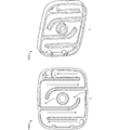
図1A、図1B、図2A、図2B、図2C、図4A、図4B、図5A、図5B、図6A、図6B、図7A、および図7Bは、本開示の少なくともいくつかの例に従った様々な燃料電池カートリッジ例100、200、220、240、400、500、600、620、700の略図である。いくつかの例では、燃料電池カートリッジ(または単に、カートリッジ)100、200、220、240、400、500、600、620、700は、水モジュール102、202、222、242、402、502、602、622、702、反応器モジュール104、204、224、244、404、504、604、624、704、およびその2つの間の接合部分106、206、226、246、406、506、606、626、706を含み得る。いくつかの例では、燃料電池カートリッジ100、200、220、240、400、500、600、620、700は、燃料電池110と連結するための制御マニホールドも含み得る。いくつかの例では、燃料電池カートリッジ100、200、220、240、400、500、600、620、700は、水モジュール102、202、222、242、402、502、602、622、702と、反応器モジュール104、204、224、244、404、504、604、624、704との間の水の流れを制御するための、水制御機構112、212、232、252、412、512、612、632、712も含み得る。
1A, 1B, 2A, 2B, 2C, 4A, 4B, 5A, 5B, 6A, 6B, 7A, and 7B are provided in at least some examples of the present disclosure. 4 is a schematic illustration of various exemplary
いくつかの燃料電池カートリッジ例は、採用する水制御機構のタイプに基づき、「アクティブな」燃料電池カートリッジ200、620、700または「パッシブな」燃料電池カートリッジ100、220、240、400、500、600と見なされ得る。
Some example fuel cell cartridges are based on the type of water control mechanism employed, depending on the “active”
例えば、図2A、図6B、図7A、および図7Bの燃料電池カートリッジ200、620、700は、燃料電池カートリッジ200、620、700内に水の流れを起こして制御する外部水制御機構212、632、712のためにアクティブと見なされる。これらの外部制御機構212、632、712は、一般に、作動するために外部電力を必要とする。一般に、アクティブな燃料電池カートリッジシステム200、620、700は、ポンプ212、632,712または代替手段を利用して、要求に応じて、または他の制御変数に基づき、反応物への水の供給を制御する。アクティブシステム200、620、700は、反応器モジュール204、624、704またはチャンバーへの水の流れを電子的に制御するために水ポンプ212、632、712を使用し得るが;このアーキテクチャでは、燃料電池コストがより高くなり、かつ、燃料電池システムがより複雑になる。例えば、これらの図に示すように、水ポンプ212、632、712は、取水口、吐水口、および/または水素ガス排出口に対する流体接続を介して、燃料電池カートリッジ200、620、700と連結し得る。図に見られるように、水は、カートリッジ200、620、700から水ポンプ212、632,712を通って引き込まれ、カートリッジ200、620、700へ送り返され得る。他のアクティブなカートリッジアーキテクチャも本開示によって企図される。
For example, the
図1A、図1B、図2B、図2C、図4A、図4B、図5A、図5B、および図6Aの燃料電池カートリッジ100、220、240、400、500、600は、水の流れを燃料電池カートリッジ100、220、240、400、500、600内に起こすために外部機構を必要としないので、パッシブと見なされる。例えば、これらの図で示す燃料電池カートリッジ100、220、240、400、500、600は、その中で、水モジュール102、222、242、402、502、602からの水を反応器モジュール104、224、244、404、504、604へ流し込むばね112、232、252、412、512、612で水が圧縮される。パッシブシステム例では、水は、ばね112、232、252、412、512、612、ブラダー(bladder)、ガスの超過圧力、および/またはガスの圧力フィードバックによって加圧され得る。いくつかのパッシブシステム例100、220、240、400、500、600は、水を反応器モジュール104、224、244、404、504、604、またはチャンバーへ圧送するために、ばね112、232、252、412、512、612を使用し得る。いくつかの例では、ばね112、232、252、412、512、612は、先細にされ得、それにより、完全に圧縮された場合に非常に平らにできる。パッシブシステム100、220、240、400、500、600は、それらが電子制御を必要としないという点において好都合であり得る。
The
いくつかのパッシブ燃料電池カートリッジシステム100、220、240、400、500、600では、システムは、加圧水供給を使用して、自動制御されるようになり;水は、下流圧力が水源より低い場合に流れることができ、下流圧力が高ければ停止する。このタイプのシステムは、関与するセンサーまたはアクチュエータ要素がないので、パッシブアーキテクチャと考えられる。
In some passive fuel
いくつかの例では、「ハイブリッド」のアクティブ/パッシブアーキテクチャが提供され得、ばねが水を加圧するが、機械的アクチュエータがオン/オフ水弁を作動させる。これは、アクティブシステムの制御の高度化の多くを可能にし得るが、パッシブシステムの簡潔さの多くも提供する。例えば、弁を作動させるための作動機構は、通常、実際の水ポンプよりも作製するコストが低い構成要素を含む。かかるハイブリッドシステムは、水素出口に対する単一の流体接続のみを必要とする接合部分を有し得る。 In some examples, a “hybrid” active / passive architecture may be provided where the spring pressurizes the water while the mechanical actuator activates the on / off water valve. This may allow much of the sophistication of control of the active system, but also provides much of the simplicity of the passive system. For example, an actuation mechanism for actuating a valve typically includes components that are less expensive to make than an actual water pump. Such a hybrid system may have a junction that requires only a single fluid connection to the hydrogen outlet.
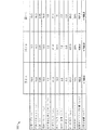
図3は、本開示の少なくともいくつかの例に従った、それぞれ図2A、図2B、および図2Cの燃料電池カートリッジ例200、220、240の特性例を示す表300である。
FIG. 3 is a table 300 illustrating example characteristics of the example
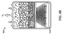
図4A、図4B、図5A、および図5Bは、本開示の少なくともいくつかの例に従ったいくつかの燃料電池カートリッジ例400、500の構造および動作を示す。図4Aおよび図4Bは、燃料電池カートリッジ例400が、筐体414および筐体414内部の仕切り406を含み得ることを示す。仕切り406は、水空洞402を反応器空洞404から分離する。しかし、仕切り406は、幾らかの水が水空洞402から反応器空洞404へ流れるのを可能にする。この例における反応器空洞404は、NaSi反応物415を貯蔵し、NaSi反応物415は、図4Bに示すように、水と接触すると水素ガスを生じる。この水素ガスは、燃料電池カートリッジ400から放出されて、カートリッジ400が連結されている燃料電池に入り得る。
4A, 4B, 5A, and 5B illustrate the structure and operation of several example
図4Aおよび図4Bは、筐体414内部に固定された仕切り406を示しているが、本開示は、水空洞402の容積および反応器空洞404の容積の両方が可動仕切り406の位置に基づき変動するように、仕切り406が筐体414内部で移動可能な例を企図する。
4A and 4B show the
図5Aおよび図5Bは、燃料電池カートリッジ例500が、図4Aおよび図4Bの例とは異なる構成ではあるが、筐体514および筐体514内部の仕切り506を含み得ることを示す。これらの図では、仕切り506は、垂直円筒構成において水空洞502を反応器空洞504から分離する。仕切り506は、基本的に、水空洞502が反応器空洞504の周りを囲むように、カートリッジ500のより大きい直径の筐体514内部の円筒である。仕切り506は、幾らかの水が水空洞502から反応器空洞504へ流れるのを可能にする。この例における反応器空洞504は、NaSi反応物515を貯蔵し、NaSi反応物515は、図5Bに示すように、水と接触すると水素ガスを生じる。この水素ガスは、燃料電池カートリッジ500から放出されて、カートリッジ500が連結されている燃料電池に入り得る。
5A and 5B illustrate that the example
作動中、水空洞102、402、502、602内のピストン112、412、512、612は、水空洞102、402、502、602内部のばね112、412、512、612が圧縮または伸長し、それ故に、燃料電池カートリッジ100、400、500、600内部の水の流れを変更するように、動き得る。水素圧力が増大すると、反応器室104、404、504、604へ流入する水が停止する。この時点で、水素圧力は、ピストン112、412、512、612を押すばね112、412、512、612によって生じた水圧と一致するか、または上回る。これにより、それ以降、追加の水素生成が停止する。燃料電池は、次いで、必要に応じて水素を消費し;それに応じて、反応器室104、404、504、604内の圧力がわずかに減少し、それ故に、追加の加圧水が反応器室104、404、504、604に流入して、さらなる水素が生成できるようになる。このプロセスが継続する。
In operation, the
いくつかの例では、ピストン112、412、512、612は、水モジュール102、402、502、602と反応器モジュール104、404、504、604との間の圧力差によって動き得る。例えば、図4Aは、「フレッシュ」状態のピストン112、412、512、612を示す。空気間隙116、416、516、616内には幾分かの正圧/不活性ガス/空気がある。空気間隙116、416、516、616は、多孔質フィルタ要素を含み得る。燃料電池カートリッジ100、400、500、600が燃料電池システムと係合するときにピストン112、412、512、612開口部/弁が開くと、この圧力が解放されて、ばね112、412、512、612およびピストン112、412、512、612が上方に移動して水を押し、逆止弁を通って反応物115、415、515、615(例えば、NaSi)と反応する。水素ガスが、次いで、(図4Bに示すように)空気間隙116、416、516、616を充填して出る。燃料電池システムが切り離されると、水素ガス圧力は、(図1Aに示すように)ばね112、412、512、612を適切な位置に保って、逆止弁を閉じる。余分な圧力は安全弁を通って解放され得る。
In some examples, the
ピストン112、412、512、612が第1の位置にある場合、ばね112、412、512、612は伸長され得、かつ水は水空洞102、402、502、602内に留まり得て、反応器空洞104、404、504、604内の反応物115、415、515、615と反応しない。ピストン112、412、512、612が動くと、(図5Bに示すように)ばね112、412、512、612が圧縮し始め得、水が水空洞102、402、502、602から反応器空洞104、404、504、604に流入し始め得て、水は、反応器空洞104、404、504、604内の反応物115、415、515、615と反応し始めて、水素ガスを生じ得る。ピストン112、412、512、612が第2の位置に移動すると、水空洞102、402、502、602からの水の全部または実質的に全部が反応器空洞104、404、504、604内に入るように、ばね112、412、512、612が圧縮されて、再び水素ガスを生じ得る。水素ガスは、ガス排出口を通って燃料電池カートリッジ100、400、500、600から放出され得、ガス排出口は燃料電池と流体連結され得る。
When the
図7Aおよび図7Bは、本開示の少なくともいくつかの例に従った別の燃料電池カートリッジ例700を概略的に示す。これらのカートリッジ700は、水モジュール702の内部の(または、水モジュール702を画定する)ブラダー712、およびブラダー712と燃料電池カートリッジ700の側壁との間に画定された反応器モジュール704を含むアクティブカートリッジである。ブラダー712は、拡張または縮小して、カートリッジ700内部の流体の圧力を変更し得る。カートリッジ700における圧力の変化は、カートリッジ700内の流体の流れを変更する。例えば、図7Aは、ブラダー712が、水ポンプ712からの水で比較的いっぱいであることを示している。水ポンプ712が水を反応物/燃料715(例えば、NaSi)に送り込むと、図7Bに示すように、ブラダー712の内部の水が燃料電池カートリッジ700から出る。これにより、反応器モジュール704内に水/反応物の混合物のための余地が増える。反応物715と水の化学反応は、いくつかの例では、水素ガスおよび他の副生成物(例えば、廃棄物)を生じ得る。水素ガスは、ガス排出口を通って燃料電池カートリッジ700から放出され得、ガス排出口は燃料電池と流体連結され得る。
7A and 7B schematically illustrate another example
図8は、アクティブな燃料電池カートリッジと併用するための詳細なコントローラ例800を概略的に示す。この比例積分微分(PID)コントローラは、水反応系に関するポンプとともに利用され得る。この構成では、燃料電池電流が、現在の水素消費率を計算するために使用される。反応した%、水反応混合物タイプ、環境温度、および他のパラメータを包含するシステムモデルに基づき、必要な公称水流量が推定され得る。圧力は、燃料電池カートリッジ内の実際の水素圧力対所望の水素圧力に基づき、誤差を生成するために使用され得る。圧力誤差およびシステムモデルは、PID制御ループにより、その後、燃料電池カートリッジ内の実際の水流量を制御するために使用され得る。他の制御パラメータおよびルックアップテーブルもこの例に含まれる。例えば、提示したシステムでは、システムの圧力が増大するにつれて、ポンプから実際に供給される水流が減少し得る。システムモデルおよびポンプ駆動は、生成されたルックアップテーブルで適切に補われ得る。 FIG. 8 schematically illustrates a detailed controller example 800 for use with an active fuel cell cartridge. This proportional integral derivative (PID) controller can be utilized with a pump for a water reaction system. In this configuration, the fuel cell current is used to calculate the current hydrogen consumption rate. Based on a system model that includes% reacted, water reaction mixture type, ambient temperature, and other parameters, the required nominal water flow rate can be estimated. The pressure can be used to generate an error based on the actual hydrogen pressure in the fuel cell cartridge versus the desired hydrogen pressure. The pressure error and system model can then be used by the PID control loop to control the actual water flow in the fuel cell cartridge. Other control parameters and lookup tables are also included in this example. For example, in the system presented, the water flow actually supplied from the pump may decrease as the system pressure increases. The system model and pump drive can be appropriately supplemented with the generated lookup table.
図9は、パッシブな燃料電池カートリッジ例900を概略的に示す。本開示は、従来の燃料電池(FC)は通常、燃料電池によって消費される水素が、生成された電流+燃料クロスオーバーまたはパージ損失の総計に比例する、一定圧力で、またはそれに近い圧力で動作することを企図する。定常状態条件において、ばねから生じた水圧は、構成要素を通じたわずかな損失があるが、燃料電池の機能する圧力にほぼ等しいであろう。制御構成要素は主に、過渡的条件において利用される。例えば、システムの起動時に、燃料電池における水素圧力はゼロである。パッシブシステムを開始する場合、ばね圧と燃料電池圧との間に比較的大きな圧力差があるだろう。これにより、かなりの水スパイク(water spike)が生成でき、水スパイクは次いで、実際の水素生成時における幾らかの遅延に起因して、非常に大規模な水素圧力オーバーシュートという結果になるであろう。この水の流入を減速するために水オリフィス(R−オリフィス−H2O)が使用されて、もっと緩やかな起動を可能にする。
FIG. 9 schematically illustrates an example passive
偽の水素生成スパイクの場合には、水圧を留めるために、逆止弁などの弁が使用され得る。それができない場合は、システムを振動させ得る。 In the case of a false hydrogen production spike, a valve such as a check valve can be used to keep the water pressure. If that is not possible, the system can be vibrated.
反応器モジュールは、化学反応を通して、液体水を水素ガスに変換する。 The reactor module converts liquid water into hydrogen gas through a chemical reaction.
水素生成の偽期間(spurious period)がある場合、R−オリフィス−H2が、燃料電池によって観察される圧力を制限する。その上、水素カートリッジは、圧力安全弁(図示せず)を有し得る。高圧状態の場合、R−オリフィス−H2は、過剰なガス圧力が、燃料電池に伝達されるのではなく、排出できるようにする。 If there is a spurious period of hydrogen generation, R-orifice-H2 limits the pressure observed by the fuel cell. In addition, the hydrogen cartridge may have a pressure relief valve (not shown). In the high pressure state, the R-orifice-H2 allows excess gas pressure to be exhausted rather than transmitted to the fuel cell.
水弁は、水を制御して反応をオンまたはオフにするために使用され得る。弁は、カートリッジが燃料電池に機械的に結合されると、水流条件に対して閉じるように構成できる。いくつかの例では、アクチュエータが弁のオンまたはオフを制御するために使用されて、パッシブアーキテクチャに対して追加の制御を提供できる。図では、冗長性のために、2つの水弁が示されている。単一の水弁と単一の水素弁、または複数の水弁および/もしくは複数の水素弁などの他の構成も、本開示の範囲内である。 The water valve can be used to control the water to turn the reaction on or off. The valve can be configured to close against water flow conditions when the cartridge is mechanically coupled to the fuel cell. In some examples, an actuator can be used to control the valve on or off to provide additional control over the passive architecture. In the figure, two water valves are shown for redundancy. Other configurations such as a single water valve and a single hydrogen valve, or multiple water valves and / or multiple hydrogen valves are also within the scope of this disclosure.
図10は、シリコンブラダーが水モジュールの内部で膨張する非ばねベースの圧力機構を備えた燃料電池カートリッジ部例1000を示す。示された構成では、ブラダーは、水を収容すること、水を加圧すること、水モジュールキャップにおいてチャネルシールを水モジュール筐体接合部分に提供すること、および水モジュールキャップにおいて水素シールをモジュール筐体接合部分に提供することを含む、複数の機能を有し得る。
FIG. 10 shows an example fuel
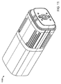
図11〜図20Bは、本開示の少なくともいくつかの例に従った、燃料電池カートリッジ例1100、1200、1300およびその部分1400、1500、1600、1700、1800、1900、2000、2100の様々な構造および動作の態様を示す。これらの図における燃料電池カートリッジ例1100、1200、1300およびその部分1400、1500、1600、1700、1800、1900、2000、2100は、可搬性が要因であり得る用途に対して使用され得る。いくつかの構成例では、そのカートリッジ例1100、1200、1300は、66cc/分の水素ガスを出力し得、それは、5Wの正味電力とほぼ同等である。各カートリッジ1100、1200、1300は、少なくとも19リットルの水素ガスを出力可能であり得、それは、約25W時のエネルギーに相当する。カートリッジ1100、1200、1300は、反応物、ナトリウムシリサイド(sodium silicide)またはナトリウムシリサイド/水素化ホウ素ナトリウムの混合物などの、水反応物質を使用し得る。水反応物質は、水と結合すると水素を生じる。
FIGS. 11-20B illustrate various configurations of example
図11〜図20Bの燃料電池カートリッジ例1100、1200、1300およびその部分1400、1500、1600、1700、1800、1900、2000、2100では、加圧水が反応器モジュール1204、1304、1404に入って水と接触すると、反応が始まり、水素圧力が対応して増大する。水素圧力が増大すると、反応器モジュール1204、1304、1404に流入している水が停止する。この時点で、水素圧力は、ピストンを押すばねによって生じた水圧と一致するか、または上回る。これにより、それ以降、追加の水素生成が停止する。燃料電池カートリッジ1100、1200、1300に連結された燃料電池は、次いで、必要に応じて水素を消費し得;それに応じて、反応器モジュール1204、1304、1404内の圧力がわずかに減少し、それ故に、追加の加圧水が反応器モジュール1204、1304、1404に流入して、さらなる水素が生成できるようになる。このプロセスは必要に応じて継続して、水素の制御された生成および燃料電池への放出をもたらす。
In the example
いくつかの例では、反応器モジュール1204、1304、1404は、水モジュール1202、1302、1402、1602、1702、1802、1902、2002から独立したエンティティ(separate entity)として作製され得、それは、工場またはサービスセンターのいずれかで完全なカートリッジに組み立てられ得る。この目的を達成するために、開発されたカートリッジは3つの主要な構成要素:反応器モジュール1204、1304、1404、水モジュール1202、1302、1402、1602、1702、1802、1902、2002、およびカートリッジ筐体1214、1314を含む。
In some examples, the
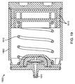
反応器モジュール1204、1304、1404は、NaSi/Na4BH4燃料、ならびに上部および下部に、水素が反応器モジュール1204、1304、1404から全ての方向に放出できるガス透過性膜を含み得る。反応器モジュール1204、1304、1404は、散水器(water spreader)も含み得、散水器は、反応器モジュール1204、1304、1404内部において、ほぼ200の位置で水を散布する。この散水器は、水の散布を均等に制御するように構成され得る。図15Aおよび図15Bに示すように、スリップオン式の濾過キャップ1500が、ガス流路を長くして、濾過媒体への曝露を拡張するための迷路構造内で使用され得る。いくつかの例では、反応器筐体は反応器モジュール1204、1304、1404の側壁を補強し、潜在的な液漏れを捕捉して、放出される水素がフィルタモジュールへ入るための経路を提供する。反応器モジュール1204、1304、1404および濾過モジュールの両方は、この反応器モジュール筐体内部に収容され得る。反応器モジュール1204、1304、1404は、筐体側壁上のスナップ式の結合機構(例えば、磁気)を利用して、それを水モジュール1202、1302、1402、1602、1702、1802、1902、2002に取り付ける。バンドまたは複数のバンド1225、1325は、ガスシールに圧力を印加するために接合点で使用されて、反応器モジュール筐体クリップ上の曲げ応力を最小限にし得、かつ、カートリッジを耐タンパー性にする。
水モジュール1802、1902上の反応器モジュールへの接合部分1811、1911は、ガスおよび液体が水モジュールへ、または水モジュールから流れるための密封された通路を提供する突起特徴を有し得る。少なくとも1つのポートが液体専用にされ得、少なくとも1つのポートがガス専用にされ得る。この接合部分1811、1911は、水モジュール1802、1902が異なる反応器モジュールで再使用できるようにする。
The
水モジュール1802、1902は、水素を燃料電池にもたらすのに十分な大量の水を含み得、水供給/制御機構を含み得る。このモジュールは、水貯蔵器、水圧のためのばね、燃料電池接合部分で作動される水弁、再充填用グロメット(refilling grommet),水制御オリフィス、および水素出口オリフィスを含み得る。パッシブなばね懸架式水噴射が圧力差を用いて水供給を駆動し得る。このアーキテクチャを用いると、燃料カートリッジ内のより低い圧力によって、圧力を均等にするための水のより高速な噴射が可能になる。同様に、カートリッジ内で水素生成率が過度に高くなると、水噴射プロセスが完全に停止し得る。
The
プランジャー1813、1913は、水を吐水口および反応器モジュールへ押し入れ得る。プランジャー1813、1913は、任意の形状であり得、とりわけ、長方形、半長方形、および円形などの断面形状を有することを含む。プランジャー1813、1913は、本明細書に記載のチャネル1617、1717内の2つのコーナー上を水/ガスが通過できるようにする。代替設計では、ガス/水経路1617、1717の組合せを4つ全てのコーナー上に含み得る。水および/またはガス濾過が、必要に応じて、それらの経路1617、1717に追加され得る。経路1617、1717は、プランジャー1813、1913が対称的な形状を維持するようにカスタマイズでき、対称的な形状は密封をさらに容易にし得る。
作動弁が水流出を制御するために適切な位置にある;これは、燃料電池が係合された後にのみ水素の供給を確実にする。 The actuating valve is in the proper position to control water outflow; this ensures a hydrogen supply only after the fuel cell is engaged.
いくつかの例では、グロメットは、モジュールがサービスセンターで充填される場合に繰り返して再使用できるように、使用後にモジュールに水を再充填するために使用され得る。グロメット、または類似の機構は、水モジュールが充填されるときに水を水モジュールに入れることができるようにするため、および水モジュール内部からの水圧に耐える際に漏れを防ぐために、使用できる。グロメットは、小さな穴に圧入され得る。従って、それは、常に圧縮状態にあり得、それは、堅牢な水シールを提供するために必要である。デュロメーター、引裂強度、および厚さは全て、カスタマイズされるパラメータであり得る。 In some examples, the grommets can be used to refill the module after use so that it can be reused repeatedly when the module is filled at a service center. A grommet, or similar mechanism, can be used to allow water to enter the water module when the water module is filled and to prevent leakage in withstanding water pressure from within the water module. The grommet can be pressed into a small hole. Thus, it can always be in a compressed state, which is necessary to provide a robust water seal. Durometer, tear strength, and thickness can all be customized parameters.
図18A、図18B、および図19に詳細に示すように、水は、水供給の自動制御を可能にするために反応器モジュールに対して調整された、所望の力対歪みプロファイルで、ばね1812、1912を使用して加圧され得る。水は、下流の圧力が、ある歪みにおけるばね力よりも低い場合に反応器モジュールに供給され、下流の圧力が高すぎる場合に停止する。水は、水モジュールから逆止弁を通って供給される。この調整機能は、追加の水が反応物に振動的かつ過剰に供給されるのを防ぎ得る。それは、生成物および/または副生成物が上流の水源まで流れるのを防ぐためにも使用され得る。
As shown in detail in FIGS. 18A, 18B, and 19, the water is
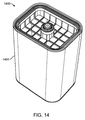
図17に示すように、水モジュール1702は、ガスまたは液体を、水モジュール1702本体の長さに沿って制御マニホールドまで運ぶためのチャネル1717を含み得る。これは、制御マニホールドがカートリッジの一方の端部に配置できるようにし得る。これは、再使用可能な接合部分の設計を可能にして、制御ハードウェアの実装を単純化し得る。
As shown in FIG. 17, the
水モジュール1602、1702、1802、1902、2002は、カートリッジ内に残っている燃料の量を容易に視覚化できるようにするために、透明であり得る。
The
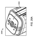
図20Aに示すように、カートリッジ接合部分が燃料電池システムと結合すると、弁が作動して、流れが制御マニホールドを通過できるようにする。カートリッジが分離されると、弁は遮断位置に戻って、水およびガス流チャネルが漏れを防ぐために密封される。これらのポペット弁は、カスタムウェーブのあるばね、および/または端面シールの適切な圧縮を提供するためのカスタムサイズにされた圧縮ばねで留められる。 As shown in FIG. 20A, when the cartridge interface is coupled to the fuel cell system, the valve is activated to allow flow to pass through the control manifold. When the cartridge is separated, the valve returns to the shut-off position and the water and gas flow channels are sealed to prevent leakage. These poppet valves are clamped with custom wavy springs and / or custom sized compression springs to provide proper compression of the end face seal.
カートリッジ/燃料電池接合部分は、制御マニホールドを含み得、燃料電池をカートリッジに磁気的に接合し得る。このように、燃料電池をカートリッジに容易に「スナップ留め」して、これを簡便な電力供給システムにする。燃料電池上の2本のピンがカートリッジ内の水弁を押し下げ得る。構成要素が正しく接合されると、水が反応器モジュールに流入できるようにする。システムが取り外されると、金属板が解放されて、水弁が閉位置で再度密封し、このようにして、水の流れを停止する。このカートリッジ/燃料電池接合部分の独特の設計は、カートリッジが燃料電池と正しく接合されている場合に限り、水素が生成できるようにする。接合部分は、メモリチップデータもカートリッジから燃料電池へ伝達し得る。 The cartridge / fuel cell interface may include a control manifold and may magnetically bond the fuel cell to the cartridge. In this way, the fuel cell is easily “snapped” to the cartridge, making it a simple power supply system. Two pins on the fuel cell can push down the water valve in the cartridge. When the components are properly joined, it allows water to flow into the reactor module. When the system is removed, the metal plate is released and the water valve reseals in the closed position, thus stopping the flow of water. This unique design of the cartridge / fuel cell interface allows hydrogen to be generated only when the cartridge is properly bonded to the fuel cell. The junction may also transmit memory chip data from the cartridge to the fuel cell.
カートリッジ/燃料電池接合部分はスナップ作用により、水素ポートまたはガス排出口の周囲のガスシールで、燃料電池とカートリッジとの間の接続を固定できるようにし得る。スナップ作用は、直接的もしくは間接的にラッチを押下する必要なく、2つの部分の接続および分離を可能にする磁気または他の固定機能によって達成できる。同じ接合部分が、水弁または水素弁に機械力を印加して、水素生成を効果的に開始および停止できる。 The cartridge / fuel cell interface may be snapped so that a connection between the fuel cell and the cartridge can be secured with a gas seal around the hydrogen port or gas outlet. The snapping action can be achieved by a magnetic or other locking feature that allows the two parts to be connected and disconnected without having to press the latch directly or indirectly. The same joint can effectively start and stop hydrogen production by applying mechanical force to the water valve or hydrogen valve.
同じ接合部分が、データ通信ピンを提供できる。例えば、メモリチップがカートリッジ上に配置でき、カートリッジのシリアル番号、反応器の状態、反応した割合、または他の基本変数の読取りを容易にする。データをメモリに書き込むこともでき、有用性情報、消費情報、または燃料電池利用パラメータを書き込む。 The same joint can provide a data communication pin. For example, a memory chip can be placed on the cartridge to facilitate reading of the cartridge serial number, reactor status, percentage reacted, or other basic variables. Data can also be written to memory, writing utility information, consumption information, or fuel cell usage parameters.
水素密封のために必要なシールを圧縮するために比較的少量の磁力が必要であることがわかっている。シール例は、Oリングまたはカスタムオーバーモールドした構成要素を含み得る。 It has been found that a relatively small amount of magnetic force is required to compress the seal required for hydrogen sealing. Examples of seals can include O-rings or custom overmolded components.
図20Bに示すように、水素弁は、作動弁と同様に作動し得る。一旦、水素ポートが閉じられると、残りの水素が反応器の内側に保持され、それは、燃料節約および安全性に役立ち得る。 As shown in FIG. 20B, the hydrogen valve can operate in the same manner as the actuation valve. Once the hydrogen port is closed, the remaining hydrogen is retained inside the reactor, which can help fuel savings and safety.
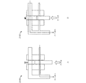
図21A、図21B、図22A、および図22Bは、本開示の少なくともいくつかの例に従った燃料電池カートリッジ例のための、スイッチング機構例2100、2200の略図である。これらの図は、水流量制御のために水オリフィス間で切り替えるための圧力作動弁例2100、2200を示す。この機構2100、2200は、反応器モジュール内部の圧力に基づき、流れが調整できるようにする。反応器モジュール内で圧力が増大すると、弁を作動させて、水流の経路または水オリフィスのいずれかを変更して異なる制約を設けることができる。この機構2100、2200は、再設定できるか、または再設定不能かのいずれかであり得る。それは、水要件が定常状態操作とは異なる場合、起動または開始/再開操作に対して有用であり得る。
21A, 21B, 22A, and 22B are schematic diagrams of
本明細書では様々な態様および実施形態が開示されているが、他の態様および実施形態が当業者には明らかであろう。本明細書で開示した様々な態様および実施形態は、説明のためであり、制限することを意図するものでなく、真の範囲および精神は以下の特許請求の範囲で示されている。 While various aspects and embodiments have been disclosed herein, other aspects and embodiments will be apparent to those skilled in the art. The various aspects and embodiments disclosed herein are for purposes of illustration and are not intended to be limiting, with the true scope and spirit being indicated by the following claims.
Claims (20)
水を貯蔵するための水モジュールと、
前記反応器モジュールと前記水モジュールを連結するための接合部分であって、前記接合部分が、前記水が前記反応器モジュール内の前記反応物と混合して、ガス排出口から放出され得るガスを形成するように、前記水が前記水モジュールから前記反応器モジュールに流れるのを可能にする、接合部分と
を備える、燃料電池カートリッジ。 A reactor module for storing reactants;
A water module for storing water;
A connecting portion for connecting the reactor module and the water module, wherein the connecting portion mixes the water with the reactants in the reactor module and discharges a gas that can be discharged from a gas outlet; A fuel cell cartridge comprising: a junction to allow the water to flow from the water module to the reactor module.
請求項1に記載の燃料電池カートリッジ。 Further comprising a water control mechanism disposed within the water module, wherein the water control mechanism is configured to control the flow of water between the water module and the reactor module;
The fuel cell cartridge according to claim 1.
前記流体が、前記少なくとも1つのチャネルを経て前記水モジュールと前記反応器モジュールとの間を流れる、
請求項1に記載の燃料電池カートリッジ。 The water module includes at least one channel extending from a first end of the water module to a second end of the water module, the at least one channel allowing fluid to pass therethrough. Made possible and
The fluid flows between the water module and the reactor module via the at least one channel;
The fuel cell cartridge according to claim 1.
前記水モジュールの前記第2の端部が制御マニホールドに連結されている、
請求項5に記載の燃料電池カートリッジ。 The first end of the water module is connected to the reactor module via the junction, and the second end of the water module is connected to a control manifold;
The fuel cell cartridge according to claim 5.
前記反応器モジュールが反応物で再充填され得る、
請求項1に記載の燃料電池カートリッジ。 The water module can be refilled with water, and the reactor module can be refilled with reactants;
The fuel cell cartridge according to claim 1.
水モジュールの第1の端部を反応器モジュールに連結することであって、前記水モジュールが水を貯蔵し、かつ、前記反応器モジュールが反応物を貯蔵する、水モジュールの第1の端部を反応器モジュールに連結することと、
前記水モジュール内の前記水の少なくとも一部が前記反応器モジュール内の前記反応物と混合し、それにより前記水素ガスを生じるように、前記水モジュールと前記反応器モジュールとの間の前記水の前記流れを制御することと、
を含む、方法。 A method for producing hydrogen gas, the method comprising:
Connecting a first end of a water module to a reactor module, wherein the water module stores water and the reactor module stores a reactant. Connecting to the reactor module;
The water between the water module and the reactor module such that at least a portion of the water in the water module mixes with the reactants in the reactor module, thereby producing the hydrogen gas. Controlling the flow;
Including the method.
請求項13に記載の方法。 Further comprising directing the hydrogen gas through at least one channel in the water module to a control manifold coupled to a second end of the water module;
The method of claim 13.
請求項13に記載の方法。 Further comprising coupling the control manifold to a fuel cell such that the hydrogen gas is released from the control manifold and enters the fuel cell.
The method of claim 13.
筐体と、
前記筐体内部に配置された接合部分であって、前記接合部分が、前記筐体内に、少なくとも1つの反応器空洞および少なくとも1つの水空洞を画定し、前記少なくとも1つの反応器空洞が前記少なくとも1つの水空洞と流体連結していて、前記反応器空洞内の反応物が前記水空洞からの水と接触して水素ガスを生じる、前記筐体内部に配置された接合部分と、
前記水素ガスを排出するための前記筐体内の排出口と
を備える、水素ガス製造システム。 A hydrogen gas production system,
A housing,
A joining portion disposed within the housing, the joining portion defining at least one reactor cavity and at least one water cavity within the housing, wherein the at least one reactor cavity is the at least one; A joint disposed within the housing that is fluidly connected to one water cavity and wherein the reactants in the reactor cavity contact the water from the water cavity to produce hydrogen gas;
A hydrogen gas production system comprising: an exhaust port in the housing for discharging the hydrogen gas.
Applications Claiming Priority (3)
| Application Number | Priority Date | Filing Date | Title |
|---|---|---|---|
| US201461955357P | 2014-03-19 | 2014-03-19 | |
| US61/955,357 | 2014-03-19 | ||
| PCT/US2015/021557 WO2015143212A1 (en) | 2014-03-19 | 2015-03-19 | Fuel cell cartridge |
Publications (1)
| Publication Number | Publication Date |
|---|---|
| JP2017510037A true JP2017510037A (en) | 2017-04-06 |
Family
ID=54145344
Family Applications (1)
| Application Number | Title | Priority Date | Filing Date |
|---|---|---|---|
| JP2016557987A Pending JP2017510037A (en) | 2014-03-19 | 2015-03-19 | Fuel cell cartridge |
Country Status (5)
| Country | Link |
|---|---|
| US (1) | US10355295B2 (en) |
| EP (1) | EP3120404A4 (en) |
| JP (1) | JP2017510037A (en) |
| CN (1) | CN106575779A (en) |
| WO (1) | WO2015143212A1 (en) |
Families Citing this family (3)
| Publication number | Priority date | Publication date | Assignee | Title |
|---|---|---|---|---|
| SE540499C2 (en) | 2016-01-05 | 2018-09-25 | Myfc Ab | Distribution of reactant solution in a fuel cartridge |
| SE540539C2 (en) | 2016-01-05 | 2018-09-25 | Myfc Ab | Fuel cartridge |
| CN114477085B (en) * | 2022-01-19 | 2024-01-05 | 中国电建集团吉林省电力勘测设计院有限公司 | Hydrogen energy synthesis system |
Citations (5)
| Publication number | Priority date | Publication date | Assignee | Title |
|---|---|---|---|---|
| JP2006069869A (en) * | 2004-09-06 | 2006-03-16 | Materials & Energy Research Institute Tokyo Ltd | Hydrogen generation method, hydrogen generation device and fuel cell system |
| JP2009039710A (en) * | 2007-07-13 | 2009-02-26 | Commiss Energ Atom | Potable gas generation device and electric fuel cell power source equipped with the same |
| JP2009230902A (en) * | 2008-03-19 | 2009-10-08 | Aquafairy Kk | Fuel cell |
| JP2013049584A (en) * | 2011-08-30 | 2013-03-14 | Seiko Instruments Inc | Hydrogen generator and fuel cell |
| JP2013518805A (en) * | 2010-02-08 | 2013-05-23 | エバレデイ バツテリ カンパニー インコーポレーテツド | Fuel cell cartridge |
Family Cites Families (11)
| Publication number | Priority date | Publication date | Assignee | Title |
|---|---|---|---|---|
| GB0021386D0 (en) | 2000-09-01 | 2000-10-18 | Secr Defence | Hydrogen source |
| US8002853B2 (en) * | 2003-07-29 | 2011-08-23 | Societe Bic | Hydrogen-generating fuel cell cartridges |
| US7481858B2 (en) * | 2005-02-25 | 2009-01-27 | Societe Bic | Hydrogen generating fuel cell cartridges |
| US20050162122A1 (en) | 2004-01-22 | 2005-07-28 | Dunn Glenn M. | Fuel cell power and management system, and technique for controlling and/or operating same |
| US7316788B2 (en) | 2004-02-12 | 2008-01-08 | Battelle Memorial Institute | Materials for storage and release of hydrogen and methods for preparing and using same |
| US7285142B1 (en) | 2006-04-28 | 2007-10-23 | University Of Central Florida Research Foundation, Inc. | Catalytic dehydrogenation of amine borane complexes |
| JP4280784B2 (en) * | 2007-07-06 | 2009-06-17 | 三菱鉛筆株式会社 | Gas generator |
| JP5631324B2 (en) * | 2008-11-03 | 2014-11-26 | ソシエテ ビックSociete Bic | Gas generator |
| MX2011010292A (en) * | 2009-03-30 | 2012-01-27 | Signa Chemistry Inc | Hydrogen generation systems and methods utilizing sodium silicide and sodium silica gel materials. |
| US8951312B2 (en) * | 2011-11-09 | 2015-02-10 | Alvin Gabriel Stern | Compact, safe and portable hydrogen generation apparatus for hydrogen on-demand applications |
| GB2511566B (en) * | 2013-03-08 | 2018-09-26 | Intelligent Energy Ltd | Gas supply cartridge |
-
2015
- 2015-03-19 WO PCT/US2015/021557 patent/WO2015143212A1/en active Application Filing
- 2015-03-19 CN CN201580014913.1A patent/CN106575779A/en active Pending
- 2015-03-19 JP JP2016557987A patent/JP2017510037A/en active Pending
- 2015-03-19 EP EP15764542.5A patent/EP3120404A4/en not_active Withdrawn
-
2016
- 2016-09-15 US US15/266,958 patent/US10355295B2/en not_active Expired - Fee Related
Patent Citations (5)
| Publication number | Priority date | Publication date | Assignee | Title |
|---|---|---|---|---|
| JP2006069869A (en) * | 2004-09-06 | 2006-03-16 | Materials & Energy Research Institute Tokyo Ltd | Hydrogen generation method, hydrogen generation device and fuel cell system |
| JP2009039710A (en) * | 2007-07-13 | 2009-02-26 | Commiss Energ Atom | Potable gas generation device and electric fuel cell power source equipped with the same |
| JP2009230902A (en) * | 2008-03-19 | 2009-10-08 | Aquafairy Kk | Fuel cell |
| JP2013518805A (en) * | 2010-02-08 | 2013-05-23 | エバレデイ バツテリ カンパニー インコーポレーテツド | Fuel cell cartridge |
| JP2013049584A (en) * | 2011-08-30 | 2013-03-14 | Seiko Instruments Inc | Hydrogen generator and fuel cell |
Also Published As
| Publication number | Publication date |
|---|---|
| CN106575779A (en) | 2017-04-19 |
| EP3120404A4 (en) | 2018-04-11 |
| WO2015143212A9 (en) | 2016-05-06 |
| EP3120404A1 (en) | 2017-01-25 |
| US20170005349A1 (en) | 2017-01-05 |
| WO2015143212A1 (en) | 2015-09-24 |
| US10355295B2 (en) | 2019-07-16 |
Similar Documents
| Publication | Publication Date | Title |
|---|---|---|
| CA2597221C (en) | Hydrogen generating fuel cell cartridges | |
| CA2597139C (en) | Hydrogen generating fuel cell cartridges | |
| CN103629406B (en) | Hydrogen-generating fuel cell cartridges | |
| EP3006803B1 (en) | Hydrogen generating fuel cell cartridges | |
| US8632928B2 (en) | Water reactive hydrogen fuel cell power system | |
| EP2726405B1 (en) | Hydrogen gas generator | |
| US10355295B2 (en) | Fuel cell cartridge | |
| US9174843B2 (en) | Valve having concentric fluid paths | |
| US20150207161A1 (en) | Hydrogen Generator System With Liquid Interface |
Legal Events
| Date | Code | Title | Description |
|---|---|---|---|
| A621 | Written request for application examination |
Free format text: JAPANESE INTERMEDIATE CODE: A621 Effective date: 20180220 |
|
| A977 | Report on retrieval |
Free format text: JAPANESE INTERMEDIATE CODE: A971007 Effective date: 20180824 |
|
| A131 | Notification of reasons for refusal |
Free format text: JAPANESE INTERMEDIATE CODE: A131 Effective date: 20180904 |
|
| A601 | Written request for extension of time |
Free format text: JAPANESE INTERMEDIATE CODE: A601 Effective date: 20181115 |
|
| A601 | Written request for extension of time |
Free format text: JAPANESE INTERMEDIATE CODE: A601 Effective date: 20190128 |
|
| A521 | Request for written amendment filed |
Free format text: JAPANESE INTERMEDIATE CODE: A523 Effective date: 20190301 |
|
| A131 | Notification of reasons for refusal |
Free format text: JAPANESE INTERMEDIATE CODE: A131 Effective date: 20190806 |
|
| A02 | Decision of refusal |
Free format text: JAPANESE INTERMEDIATE CODE: A02 Effective date: 20200331 |