JP2017509978A - Event-based reasoning and learning for stochastic spiking Bayesian networks - Google Patents
Event-based reasoning and learning for stochastic spiking Bayesian networks Download PDFInfo
- Publication number
- JP2017509978A JP2017509978A JP2016553286A JP2016553286A JP2017509978A JP 2017509978 A JP2017509978 A JP 2017509978A JP 2016553286 A JP2016553286 A JP 2016553286A JP 2016553286 A JP2016553286 A JP 2016553286A JP 2017509978 A JP2017509978 A JP 2017509978A
- Authority
- JP
- Japan
- Prior art keywords
- event
- output
- input event
- input
- node state
- Prior art date
- Legal status (The legal status is an assumption and is not a legal conclusion. Google has not performed a legal analysis and makes no representation as to the accuracy of the status listed.)
- Pending
Links
Images


Classifications
-
- G—PHYSICS
- G06—COMPUTING; CALCULATING OR COUNTING
- G06N—COMPUTING ARRANGEMENTS BASED ON SPECIFIC COMPUTATIONAL MODELS
- G06N3/00—Computing arrangements based on biological models
- G06N3/02—Neural networks
- G06N3/08—Learning methods
-
- G—PHYSICS
- G06—COMPUTING; CALCULATING OR COUNTING
- G06N—COMPUTING ARRANGEMENTS BASED ON SPECIFIC COMPUTATIONAL MODELS
- G06N3/00—Computing arrangements based on biological models
- G06N3/02—Neural networks
- G06N3/04—Architecture, e.g. interconnection topology
- G06N3/049—Temporal neural networks, e.g. delay elements, oscillating neurons or pulsed inputs
-
- G—PHYSICS
- G06—COMPUTING; CALCULATING OR COUNTING
- G06N—COMPUTING ARRANGEMENTS BASED ON SPECIFIC COMPUTATIONAL MODELS
- G06N7/00—Computing arrangements based on specific mathematical models
- G06N7/01—Probabilistic graphical models, e.g. probabilistic networks
Abstract
事象に基づくベイジアン推論および学習を行う方法は、各ノードにおいて入力事象を受信することを含む。方法は、中間値を得るために入力事象にバイアス重みおよび/または結合重みを加えることも含む。方法は、中間値に基づいてノード状態を決定することをさらに含む。さらに、方法は、確率論的点過程により出力事象を生成するためにノード状態に基づいて事後確率を表す出力事象率を計算することを含む。A method for event-based Bayesian inference and learning includes receiving an input event at each node. The method also includes adding bias weights and / or joint weights to the input event to obtain an intermediate value. The method further includes determining a node state based on the intermediate value. Further, the method includes calculating an output event rate that represents the posterior probability based on the node state to generate an output event by a stochastic point process.
Description
[0001] 本出願は、2014年2月21日に出願された米国仮特許出願第61/943,147号、および2014年3月6日に出願された米国仮特許出願第61/949,154号の利益を主張するものであり、それらの開示は、ここにおける引用によってそれらの全体が明示で組み入れられている。 [0001] This application is based on US Provisional Patent Application No. 61 / 943,147, filed February 21, 2014, and US Provisional Patent Application No. 61 / 949,154, filed March 6, 2014. All of which are expressly incorporated by reference herein in their entirety.
[0002] 本開示の幾つかの態様は、概して、ニューラルシステム工学に関するものであり、より具体的には、確率論的スパイキングベイジアンネットワークに関する事象に基づく推論および学習のためのシステムおよび方法に関するものである。 [0002] Some aspects of the present disclosure relate generally to neural system engineering, and more specifically to systems and methods for event-based reasoning and learning for probabilistic spiking Bayesian networks. It is.
[0003] 相互に結合された人工ニューロンのグループ(すなわち、ニューロンモデル)を備えることができる人工的なニューラルネットワークは、計算デバイスであるかまたは計算デバイスによって実行される方法を表す。人工的なニューラルネットワークは、生物学上のニューラルネットワークにおける対応する構造および/または機能を有することができる。しかしながら、人工的なニューラルネットワークは、伝統的な計算技法が厄介である、非実際的である、または不適切である幾つかの用途に関する革新的で有用な計算技法を提供することができる。人工的なニューラルネットワークは、観測から機能を推論することができるため、該ネットワークは、タスクまたはデータの複雑さが従来の技法を負担のかかるものにする用途において特に有用である。 [0003] An artificial neural network that can comprise a group of artificial neurons (ie, a neuron model) coupled together represents a method that is or is performed by a computing device. An artificial neural network can have a corresponding structure and / or function in a biological neural network. However, artificial neural networks can provide innovative and useful computational techniques for some applications where traditional computational techniques are cumbersome, impractical, or inappropriate. Since artificial neural networks can infer functionality from observations, they are particularly useful in applications where task or data complexity makes traditional techniques burdensome.
[0004] 本開示の一態様において、方法は、事象に基づくベイジアン推論および学習を行う。方法は、1つのグループのノードの各々において入力事象を受信することを含む。方法は、中間値を得るために入力事象にバイアス重みおよび/または結合重みを加えることも含む。さらに、方法は、中間値に基づいてノード状態を決定することを含む。方法は、確率論的点過程により出力事象を生成するためにノード状態に基づいて事後確率を表す出力事象率を計算することをさらに備える。
[0005] 本開示の他の態様において、装置は、事象に基づくベイジアン推論および学習を行う。装置は、メモリと、1つ以上のプロセッサと、を含む。プロセッサは、メモリに結合される。プロセッサは、一組のノードの各々において入力事象を受信するように構成される。プロセッサは、中間値を得るために入力事象にバイアス重みおよび/または結合重みを加えるようにも構成される。さらに、プロセッサは、中間値に基づいてノード状態を決定するように構成される。プロセッサは、確率論的点過程により出力事象を生成するためにノード状態に基づいて事後確率を表す出力事象率を計算するようにさらに構成される。
[0006] さらに他の態様において、事象に基づくベイジアン推論および学習を行うための装置が開示される。装置は、一組のノードの各々において入力事象を受信するための手段を有する。装置は、中間値を得るために入力事象にバイアス重みおよび/または結合重みを加えるための手段も有する。さらに、装置は、中間値に基づいてノード状態を決定するための手段を有する。さらに、装置は、確率論的点過程により出力事象を生成するためにノード状態に基づいて事後確率を表す出力事象率を計算するための手段を有する。
[0007] 本開示のさらに他の態様において、事象に基づくベイジアン推論および学習を行うためのコンピュータプログラム製品が開示される。コンピュータプログラム製品は、プログラムコードを符号化(encode)している非一時的なコンピュータ読み取り可能媒体を含む。プログラムコードは、一組のノードの各々において入力事象を受信するためのプログラムコードを含む。プログラムコードは、中間値を得るために入力事象にバイアス重みおよび/または結合重みを加えるためのプログラムコードも含む。さらに、プログラムコードは、中間値に基づいてノード状態を決定するためのプログラムコードを含む。プログラムコードは、確率論的点過程により出力事象を生成するためにノード状態に基づいて事後確率を表す出力事象率を計算するためのプログラムコードをさらに含む。
[0008] これは、後続する詳細な説明をより良く理解することができるようにするために本開示の特徴および技術上の利点をかなりおおまかに概説している。本開示の追加の特徴および利点が以下において説明される。この開示は、本開示の同じ目的を実行するためのその他の構造を変更または設計するための基礎として容易に利用できることが当業者によって認識されるべきである。該同等の構造は、添付される請求項において示される本開示の教示から逸脱するものではないことも当業者によって自覚されるべきである。その構成および動作方法の両方に関して、本開示の特徴を表すと確信される新規の特徴は、さらなる目的および利点とともに、添付される図と関係させて検討されたときに以下の説明からより良く理解されるであろう。しかしながら、各々の図は、例示および説明のみを目的として提供されるものであり、本開示の限界を定義するものであることは意図されないことが明示で理解されるべきである。
[0004] In one aspect of the present disclosure, the method performs event-based Bayesian inference and learning. The method includes receiving an input event at each of a group of nodes. The method also includes adding bias weights and / or joint weights to the input event to obtain an intermediate value. Further, the method includes determining a node state based on the intermediate value. The method further comprises calculating an output event rate that represents the posterior probability based on the node state to generate an output event by a stochastic point process.
[0005] In other aspects of the disclosure, the apparatus performs event-based Bayesian inference and learning. The apparatus includes a memory and one or more processors. The processor is coupled to the memory. The processor is configured to receive an input event at each of the set of nodes. The processor is also configured to add bias weights and / or coupling weights to the input event to obtain an intermediate value. Further, the processor is configured to determine a node state based on the intermediate value. The processor is further configured to calculate an output event rate that represents the posterior probability based on the node state to generate an output event by a probabilistic point process.
[0006] In yet another aspect, an apparatus for performing event-based Bayesian inference and learning is disclosed. The apparatus has means for receiving an input event at each of the set of nodes. The apparatus also has means for adding bias weights and / or joint weights to the input event to obtain an intermediate value. Furthermore, the apparatus has means for determining a node state based on the intermediate value. Furthermore, the apparatus has means for calculating an output event rate that represents the posterior probability based on the node state to generate an output event by a stochastic point process.
[0007] In yet another aspect of the present disclosure, a computer program product for performing event-based Bayesian inference and learning is disclosed. The computer program product includes a non-transitory computer readable medium encoding program code. The program code includes program code for receiving an input event at each of the set of nodes. The program code also includes program code for adding bias weights and / or coupling weights to input events to obtain intermediate values. Furthermore, the program code includes a program code for determining a node state based on the intermediate value. The program code further includes program code for calculating an output event rate that represents the posterior probability based on the node state to generate an output event by a probabilistic point process.
[0008] This outlined rather broadly the features and technical advantages of the present disclosure in order that the detailed description that follows may be better understood. Additional features and advantages of the present disclosure are described below. It should be appreciated by those skilled in the art that this disclosure can be readily used as a basis for modifying or designing other structures for carrying out the same purposes of the present disclosure. It should also be recognized by those skilled in the art that the equivalent structure does not depart from the teachings of the present disclosure as set forth in the appended claims. The novel features believed to be representative of the features of this disclosure, both in terms of their construction and method of operation, along with further objects and advantages, will be better understood from the following description when considered in conjunction with the accompanying figures. Will be done. However, it should be expressly understood that each drawing is provided for purposes of illustration and description only and is not intended to define the limitations of the present disclosure.
[0009] 本開示の特徴、性質、および利点は、同様の参照文字が全体を通じて相応に識別する図面と関連させたときに以下の詳細な説明からより明確になるであろう。
[0027] 添付される図面と関係させて以下において示される詳細な説明は、様々な構成に関する説明であることが意図されており、ここにおいて説明される概念を実施することができる唯一の構成を表すことは意図されていない。詳細な説明は、様々な概念に関する徹底的な理解を提供することを目的とする具体的な詳細を含む。しかしながら、これらの概念は、これらの具体的な詳細なしに実施可能であることが当業者にとって明らかになるであろう。幾つかの例において、よく知られた構造およびコンポーネントは、該概念を曖昧にすることを避けるためにブロック図の形態で示される。
[0028] 教示に基づき、本開示の適用範囲は、独立して実装されるかまたは本開示のいずれかのその他の態様と組み合わされているかにかかわらず、本開示のあらゆる態様を網羅することが意図されることを当業者は認識すべきである。例えば、装置は、示される態様のうちのあらゆる数を用いて実装することができ、方法は、示される態様のうちのあらゆる数を用いて実行することができる。さらに、本開示の適用範囲は、該装置または示される本開示の様々な態様に加えてのまたは示される本開示の様々な態様以外のその他の構造、機能、または構造と機能を用いて実行される方法を網羅することが意図される。開示される本開示のいずれの態様も、請求項の1つ以上の要素によって具現化することができることが理解されるべきである。
[0029] 単語“例示的な”は、ここでは、“例、実例、または例示”を意味するために使用される。ここにおいて“例示的な”として説明されるいずれの態様も、必ずしもその他の態様よりも好ましいまたは有利であると解釈されるべきでない。
[0030] ここにおいては特定の態様が説明されるが、これらの態様の数多くの変形および置換が本開示の適用範囲内にある。好ましい態様の幾つかの利益および利点が述べられているが、本開示の適用範囲は、特定の利益、用途または目標に限定されることは意図されない。むしろ、本開示の態様は、異なる技術、システム構成、ネットワークおよびプロトコルに対して広範囲にわたって適用可能であることが意図され、それらのうちの一部は、図内におけるおよび好ましい態様に関する以下の説明内における例として示される。詳細な説明および図面は、限定するのではなく本開示を単に例示するものであり、本開示適用範囲は、添付される請求項およびそれらの同等物によって定められる。
ニューラルシステム例、訓練および動作
[0031] 図1は、本開示の幾つかの態様による複数のレベルのニューロンを有する人工的なニューラルシステム例100を示す。ニューラルシステム100は、シナプス結合(すなわち、フィードフォワード結合)104のネットワークを通じて他のレベルのニューロンに結合された1つのレベルのニューロン102を有することができる。単純化を目的として、図1には2つのレベルのニューロンのみが例示されるが、ニューラルシステムにはそれよりも少ない又は多いレベルのニューロンが存在することができる。ニューロンのうちの一部は、側方結合を通じて同じ層のその他のニューロンに結合することができることが注目されるべきである。さらに、ニューロンのうちの一部は、フィードバック結合を通じて前層のニューロンに結合することができる。
[0032] 図1において例示されるように、レベル102内の各ニューロンは、前レベル(図1に示されていない)のニューロンによって生成することができる入力信号108を受信することができる。信号108は、レベル102ニューロンの入力電流を表すことができる。この電流は、膜電位を充電するためにニューロン膜上に蓄積することができる。膜電位がそれの閾値に達したときに、ニューロンは、発火し、次のニューロンレベル(例えば、レベル106)に伝達されるべき出力スパイクを生成することができる。幾つかのモデル化アプローチ法において、ニューロンは、次のニューロンレベルに信号を連続的に伝達することができる。この信号は、典型的には、膜電位の関数である。該挙動は、ハードウェアおよび/またはソフトウェアにおいてエミュレートまたはシミュレーションすることができ、以下において説明されるようなアナログおよびデジタル実装を含む。
[0033] 生物のニューロンにおいては、ニューロンが発火したときに生成される出力スパイクは、活動電位と呼ばれる。この電気信号は、相対的に高速で、過渡的な神経インパルスであり、約100mVの振幅および約1msの持続時間を有する。一連の結合されたニューロンを有するニューラルシステムの特定の実施形態において(例えば、図1における1つのニューロンレベルから他へのスパイクの伝達)、すべての活動電位は、基本的には、同じ振幅および持続時間を有し、従って、信号内の情報は、振幅ではなく、周波数およびスパイク数、またはスパイク時間のみによって表すことができる。活動電位によって搬送される情報は、スパイク、スパイクしたニューロン、およびその他のスパイクまたはスパイク(複数)に対するスパイク時間によって決定することができる。スパイクの重要性は、以下において説明されるように、ニューロン間の結合に加えられる重みによって決定することができる。
[0034] 1つのニューロンレベルから他へのスパイクの伝達は、図1において例示されるように、シナプス結合(または単に“シナプス”)104のネットワークを通じて達成することができる。シナプス104に対して、レベル102のニューロンは、シナプス前ニューロンとみなすことができ、レベル106のニューロンは、シナプス後ニューロンとみなすことができる。シナプス104は、レベル102のニューロンから出力信号(すなわち、スパイク)を受信し、調整可能なシナプス荷重w1 (i,i+1)、...、wP (i,i+1)によりそれらの信号をスケーリングすることができ、ここで、Pは、レベル102のニューロンとレベル106のニューロンと間のシナプス結合の総数であり、iは、ニューロンレベルのインジケータである。図1の例において、iは、ニューロンレベル102を表し、i+1は、ニューロンレベル106を表す。さらに、スケーリングされた信号は、レベル106における各ニューロンの入力信号として結合することができる。レベル106におけるすべてのニューロンは、対応する結合された入力信号に基づいて出力スパイク110を生成することができる。出力スパイク110は、(図1には示されていない)他のシナプス結合ネットワークを用いて他のニューロンレベルに伝達することができる。
[0035] 生物のシナプスは、シナプス後ニューロンでの興奮性または抑制性(過分極)活動のいずれも調停することができ、および、ニューロン信号を増幅する働きをすることもできる。興奮性信号は、膜電位を脱分極する(すなわち、静止電位に関する膜電位を高くする)。ある閾値を超えて膜電位を脱分極するためにある一定の期間内に十分な興奮性信号が受信される場合は、シナプス後ニューロンにおいて活動電位が発生する。対照的に、抑制性信号は、概して、膜電位を過分極する(すなわち、引き下げる)。抑制性信号は、十分に強い場合は、興奮性信号の和に対抗し、膜電位が閾値に達するのを防止する。シナプス興奮に対抗することに加えて、シナプス抑制は、自発的に能動的なニューロンを強力に制御することができる。自発的に能動的なニューロンとは、例えば、それの力学またはフィードバックに起因して、さらなる入力なしでスパイクするニューロンを意味する。これらのニューロンにおける活動電位の自発的な発生を抑制することによって、シナプス抑制は、ニューロンにおける発火パターンを形成することができ、そのことは、概してスカルプチャリング(sculpturing)と呼ばれる。様々なシナプス104は、希望される挙動に依存して、興奮性シナプスまたは抑制性シナプスの組み合わせとして働くことができる。
[0036] ニューラルシステム100は、汎用プロセッサ、デジタル信号プロセッサ(DSP)、特定用途向け集積回路(ASIC)、フィールドプログラマブルゲートアレイ(FPGA)またはその他のプログラマブルロジックデバイス(PLD)、ディスクリートゲートロジック、ディスクリートトランジスタロジック、ディスクリートハードウェアコンポーネントと、プロセッサによって実行されるソフトウェアモジュール、またはそれらの何らかの組み合わせによってエミュレートすることができる。ニューラルシステム100は、広範な用途、例えば、画像およびパターン認識、機械学習、モーター制御、等、において利用することができる。ニューラルシステム100内の各ニューロンは、ニューロン回路として実装することができる。出力スパイクを開始させる閾値まで荷電されたニューロン膜は、例えば、内部を流れる電流を積分するコンデンサとして実装することができる。
[0037] 一態様において、コンデンサは、ニューロン回路の電流積分デバイスとして取り除くことができ、および、より小型のメムリスタ(memristor)素子をその代わりに使用することができる。このアプローチ法は、ニューロン回路において、および、かさばるコンデンサが電流積分器として利用される様々なその他の用途において適用することができる。さらに、シナプス104の各々は、メムリスタ素子に基づいて実装することができ、ここで、シナプス荷重の変化は、メムリスタ抵抗の変化に関連することができる。ナノメートル規模のサイズのメムリスタを用いることで、ニューロン回路の面積を実質的に縮小し、シナプスを実質的に減少させることができ、大規模なニューラルシステムハードウェアの実装をより実用的にすることができる。
[0038] ニューラルシステム100をエミュレートするニューラルプロセッサの機能は、ニューロン間の結合の強度を制御することができるシナプス結合荷重に依存することができる。シナプス荷重は、プロセッサがパワーダウンされた後にプロセッサの機能を保存するために非揮発性メモリに格納することができる。一態様において、シナプス荷重メモリは、主ニューラルプロセッサチップから分離された外部のチップに実装することができる。シナプス荷重メモリは、交換可能なメモリカードとしてニューラルプロセッサとは別個にパッケージングすることができる。これは、ニューラルプロセッサに多様な機能を提供することができ、特定の機能は、ニューラルプロセッサに現在取り付けられているメモリカードに格納されたシナプス荷重に基づくことができる。
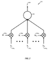
[0039] 図2は、本開示の幾つかの態様による計算ネットワーク(例えば、ニューラルシステムまたはニューラルネットワーク)の処理ユニット(例えば、ニューロンまたはニューロン回路)202の例示的な概略図200を示す。例えば、ニューロン202は、図1からのレベル102および106のニューロンのうちのいずれかに対応することができる。ニューロン202は、複数の入力信号2041乃至204Nを受信することができ、入力信号2041乃至204Nは、ニューラルシステムの外部の信号、または、同じニューラルシステムのその他のニューロンによって生成された信号、または両方であることができる。入力信号は、電流、コンダクタンス、電圧、実数値、および/または複素数値であることができる。入力信号は、固定小数点または浮動小数点表現を有する数値を備えることができる。これらの入力信号は、調整可能なシナプス荷重2061乃至206N(W1乃至WN)により信号をスケーリングするシナプス結合を通じてニューロン202に引き渡すことができ、ここで、Nは、ニューロン202の入力結合の総数であることができる。
[0040] ニューロン202は、出力信号208(すなわち、信号Y)を生成するために、スケーリングされた入力信号を結合し、結合されたスケーリングされた入力を使用することができる。出力信号208は、電流、コンダクタンス、電圧、実数値、および/または複素数値であることができる。出力信号は、固定小数点または浮動小数点表現を有する数値であることができる。次に、出力信号208は、同じニューラルシステムのその他のニューロンへの入力信号として、または、同じニューロン202への入力信号として、またはニューラルシステムの出力として、伝達することができる。
[0041] 処理ユニット(ニューロン)202は、電気回路によってエミュレートすることができ、それの入力および出力接続は、シナプス回路との電気的接続によってエミュレートすることができる。処理ユニット202およびそれの入力接続および出力接続は、ソフトウェアコードによってエミュレートすることができる。処理ユニット202は、電気回路によってエミュレートすることもでき、それの入力接続および出力接続は、ソフトウェアコードによってエミュレートすることができる。一態様において、計算ネットワーク内の処理ユニット202は、アナログ電気回路であることができる。他の態様において、処理ユニット202は、デジタル電気回路であることができる。さらに他の態様において、処理ユニット202は、アナログおよびデジタル構成要素を有する混合信号電気回路であることができる。計算ネットワークは、上記のいずれかの形態の処理ユニットを含むことができる。該処理ユニットを使用する計算ネットワーク(ニューラルシステムまたはニューラルネットワーク)は、広範な用途、例えば、画像およびパターン認識、機械学習、モーター制御、等、において利用することができる。
[0042] ニューラルネットワークの訓練中に、シナプス荷重(例えば、図1からの荷重w1 (i,i+i)、...、wP (i,i+i)および/または図2からの荷重2061乃至206N)は、学習則に従ってランダム値を用いて初期化し、増加または減少させることができる。学習則の例は、スパイク−タイミング依存可塑性(STDP)学習則、Hebb則、Oja則、Bienenstock−Copper−Munro(BCM)則、等を含むが、スパイク−タイミング依存可塑性(STDP)学習則、Hebb則、Oja則、Bienenstock−Copper−Munro(BCM)則、等に限定されないことを当業者は認識するであろう。幾つかの態様において、荷重は、2つの値のうちの1つに落ち着くまたは収束することができる(すなわち、荷重の2モード分布)。この効果は、各シナプス荷重に関するビット数を減少させるために、シナプス荷重を格納しているメモリからの読み取り速度およびメモリへの書き込み速度を上昇させるために、および、シナプスメモリの電力および/またはプロセッサ消費量を低減させるために利用することができる。
シナプスのタイプ
[0043] ニューラルネットワークのハードウェアモデルおよびソフトウェアモデルにおいて、シナプス関連機能の処理は、シナプスのタイプに基づくことができる。シナプスのタイプは、非可塑性シナプス(荷重および遅延の変化なし)、可塑性シナプス(荷重が変化することがある)、構造上の遅延可塑性シナプス(荷重および遅延が変化することがある)、完全可塑性シナプス(荷重、遅延および結合性が変化することがある)、およびそれらの変形(例えば、遅延が変化することがあるが、荷重および結合性の変化なし)であることができる。複数のタイプの利点は、処理を細分できることである。例えば、非可塑性シナプスは、実行されるべき可塑性関数を使用することができない(または、該
関数が完了するのを待つ)。同様に、遅延および荷重可塑性を、まとめてまたは別々に、順次にまたは平行して、行うことができる動作に細分することができる。異なるタイプのシナプスは、適用される異なる可塑性のタイプの各々に関して異なるルックアップテーブルまたは公式およびパラメータを有することができる。このように、方法は、シナプスのタイプに関して該当するテーブル、公式、およびパラメータにアクセスする。
[0027] The detailed description set forth below in connection with the accompanying drawings is intended as a description of various configurations and is the only configuration capable of implementing the concepts described herein. It is not intended to represent. The detailed description includes specific details that are intended to provide a thorough understanding of various concepts. However, it will be apparent to those skilled in the art that these concepts can be practiced without these specific details. In some instances, well-known structures and components are shown in block diagram form in order to avoid obscuring the concept.
[0028] Based on the teachings, the scope of the present disclosure may encompass any aspect of the present disclosure, whether implemented independently or in combination with any other aspect of the present disclosure. Those skilled in the art should recognize that this is intended. For example, an apparatus can be implemented using any number of the aspects shown and the method can be performed using any number of the aspects shown. Further, the scope of the present disclosure may be implemented using the apparatus or other structures, functions, or structures and functions in addition to or other than the various aspects of the present disclosure shown. It is intended to cover the methods. It should be understood that any aspect of the disclosure disclosed may be embodied by one or more elements of a claim.
[0029] The word “exemplary” is used herein to mean “example, instance, or illustration”. Any aspect described herein as "exemplary" is not necessarily to be construed as preferred or advantageous over other aspects.
[0030] Although particular aspects are described herein, many variations and permutations of these aspects are within the scope of the disclosure. Although some benefits and advantages of the preferred aspects are mentioned, the scope of the disclosure is not intended to be limited to particular benefits, uses, or goals. Rather, the aspects of the present disclosure are intended to be broadly applicable to different technologies, system configurations, networks and protocols, some of which are within the following description of the preferred embodiments in the figures and As an example. The detailed description and drawings are merely illustrative of the disclosure rather than limiting, the scope of the disclosure being defined by the appended claims and their equivalents.
Example neural system, training and operation
[0031] FIG. 1 illustrates an example artificial
[0032] As illustrated in FIG. 1, each neuron in
[0033] In biological neurons, the output spike that is generated when a neuron fires is called the action potential. This electrical signal is a relatively fast, transient nerve impulse, having an amplitude of about 100 mV and a duration of about 1 ms. In a particular embodiment of a neural system with a series of connected neurons (eg, transmission of spikes from one neuron level to another in FIG. 1), all action potentials are essentially the same amplitude and duration. It has time, so the information in the signal can be represented not by amplitude but by frequency and number of spikes, or only spike time. The information carried by the action potential can be determined by the spike time for spikes, spiked neurons, and other spikes or spikes. The importance of spikes can be determined by the weight applied to the connection between neurons, as will be explained below.
[0034] Transmission of spikes from one neuron level to another can be accomplished through a network of synaptic connections (or simply "synapses") 104, as illustrated in FIG. For
[0035] Biological synapses can mediate either excitatory or inhibitory (hyperpolarization) activity in post-synaptic neurons, and can also serve to amplify neuronal signals. The excitatory signal depolarizes the membrane potential (ie, increases the membrane potential relative to the resting potential). If sufficient excitatory signals are received within a certain period of time to depolarize the membrane potential beyond a certain threshold, an action potential is generated in the postsynaptic neuron. In contrast, inhibitory signals generally hyperpolarize (ie, reduce) membrane potential. If the inhibitory signal is strong enough, it counters the sum of excitatory signals and prevents the membrane potential from reaching the threshold. In addition to combating synaptic excitation, synaptic inhibition can potently control spontaneously active neurons. A spontaneously active neuron means a neuron that spikes without further input due to its dynamics or feedback, for example. By suppressing the spontaneous generation of action potentials in these neurons, synaptic inhibition can form a firing pattern in neurons, which is generally referred to as sculpting. The
The
[0037] In one aspect, the capacitor can be removed as a current integrating device of the neuron circuit, and a smaller memristor element can be used instead. This approach can be applied in neuron circuits and in various other applications where bulky capacitors are utilized as current integrators. Further, each of the
[0038] The function of the neural processor that emulates the
[0039] FIG. 2 illustrates an example schematic diagram 200 of a processing unit (eg, a neuron or neuron circuit) 202 of a computing network (eg, a neural system or neural network) according to some aspects of the present disclosure. For example, the
[0040] The
[0041] The processing unit (neuron) 202 can be emulated by an electrical circuit, and its input and output connections can be emulated by electrical connection with a synaptic circuit. The
[0042] During neural network training, synaptic loads (eg, loads w 1 (i, i + i) ,..., W P (i, i + i) from FIG. 1 and / or loads 206 1 through 1 from FIG. 206 N ) can be initialized with random values according to the learning rule and can be increased or decreased. Examples of learning rules include spike-timing dependent plasticity (STDP) learning rule, Hebb rule, Oja rule, Bienstock-Copper-Munro (BCM) rule, etc., but spike-timing dependent plasticity (STDP) learning rule, Hebb Those skilled in the art will recognize that they are not limited to the Law, Oja Law, Bienstock-Copper-Munro (BCM) Law, etc. In some aspects, the load can settle or converge to one of two values (ie, a bimodal distribution of loads). The effect is to reduce the number of bits for each synaptic load, to increase the read speed from and write to the memory storing the synaptic load, and to synaptic memory power and / or processor It can be used to reduce consumption.
Synaptic type
[0043] In the hardware model and software model of the neural network, the processing of synapse related functions can be based on the type of synapse. Synaptic types are: non-plastic synapses (no change in load and delay), plastic synapses (load may vary), structural delayed plastic synapses (load and delay may vary), fully plastic synapses (The load, delay and connectivity may change), and their deformations (eg, the delay may change, but no change in load and connectivity). The advantage of several types is that the processing can be subdivided. For example, a non-plastic synapse cannot use a plasticity function to be performed (or wait for the function to complete). Similarly, delay and load plasticity can be subdivided into operations that can be performed together or separately, sequentially or in parallel. Different types of synapses can have different look-up tables or formulas and parameters for each of the different types of plasticity applied. In this way, the method accesses the appropriate tables, formulas and parameters for the type of synapse.
[0044] スパイク−タイミングに依存する構造上の可塑性をシナプスの可塑性から独立して実行することができるという事実にはさらなる意味合いが存在する。構造上の可塑性は、荷重規模に変化がない場合でも実行することができる(例えば、荷重が最小値または最大値に達している、または何らかのその他の理由で変化されない場合、構造上の可塑性(すなわち、遅延変化量)は、スパイク前−後時間差の直接的な関数であることができる)。代替として、構造上の可塑性は、荷重変化量の関数としてまたは荷重または荷重の変化の限度に関連する条件に基づいて設定することができる。例えば、シナプス遅延は、荷重変化が生じたときのみまたは荷重がゼロに達している場合に変化することができ、ただし、荷重が最大値である場合は変化することができない。しかしながら、これらのプロセスを並行させてメモリアクセス数および重複を低減させることができるようにするために独立した機能を有するのが有利であることができる。
シナプス可塑性の決定
[0045] ニューロ可塑性(または、単に“可塑性”)は、脳内のニューロンおよびニューラルネットワークが新しい情報、感覚の刺激、発達、損傷、または機能不良に応答してそれらのシナプス結合および挙動を変えることができることである。可塑性は、生物学における学習と記憶、および計算上の神経科学およびニューラルネットワークにとって重要である。様々な形の可塑性、例えば、(例えば、Hebbian理論による)シナプス可塑性、スパイク−タイミング依存可塑性(STDP)、非シナプス可塑性、活動依存可塑性、構造上の可塑性、およびホメオスタティック可塑性、について研究されてきている。
[0044] There is a further implication of the fact that the structural plasticity depending on the spike-timing can be performed independently of the synaptic plasticity. Structural plasticity can be performed even when there is no change in load scale (eg, if the load has reached a minimum or maximum value, or is not changed for some other reason, ie structural plasticity (ie , Delay variation) can be a direct function of the time difference before and after spike). Alternatively, the structural plasticity can be set as a function of the load change or based on conditions associated with the load or limit of load change. For example, the synaptic delay can change only when a load change occurs or when the load reaches zero, but cannot change if the load is at a maximum value. However, it may be advantageous to have independent functions to allow these processes in parallel to reduce the number of memory accesses and duplication.
Determination of synaptic plasticity
[0045] Neuroplasticity (or simply “plasticity”) means that neurons and neural networks in the brain change their synaptic connections and behavior in response to new information, sensory stimulation, development, damage, or malfunction. It is possible to do. Plasticity is important for biology learning and memory, and computational neuroscience and neural networks. Various forms of plasticity have been studied, for example, synaptic plasticity (eg, according to Hebbian theory), spike-timing dependent plasticity (STDP), nonsynaptic plasticity, activity dependent plasticity, structural plasticity, and homeostatic plasticity. Yes.
[0046] STDPは、ニューロン間のシナプス結合の強度を調整する学習プロセスである。結合強度は、特定のニューロンの出力および受信された入力スパイク(すなわち、活動電位)の相対的タイミングに基づいて調整される。STDPプロセス下では、ある一定のニューロンへの入力スパイクが平均してそのニューロンの出力スパイク直前に発生する傾向がある場合に長期増強(LTP)が生じることができる。次に、その特定の入力は、多少より強くされる。他方、入力スパイクが平均して出力スパイクの直後に発生する傾向がある場合は長期抑圧(LTD)が生じることができる。次に、その特定の入力は多少より弱くされ、従って、“スパイク−タイミング依存可塑性”と呼ばれる。従って、シナプス後ニューロンの興奮の原因であると思われる入力は、将来貢献する可能性がさらにより高くなり、シナプス後スパイクの原因でない入力は、将来貢献する可能性が低くなる。このプロセスは、最初の組の結合の部分組が残り、他方すべてのその他の影響が意味のないレベルまで低下するまで継続する。 [0046] STDP is a learning process that adjusts the strength of synaptic connections between neurons. The bond strength is adjusted based on the relative timing of the output of a particular neuron and the received input spike (ie, action potential). Under the STDP process, long-term potentiation (LTP) can occur when an input spike to a certain neuron tends to occur on average just before that neuron's output spike. Then that particular input is made somewhat stronger. On the other hand, long-term suppression (LTD) can occur if the input spikes tend to occur on average immediately after the output spike. That particular input is then made somewhat weaker and is therefore referred to as “spike-timing dependent plasticity”. Thus, inputs that appear to be responsible for the excitement of post-synaptic neurons are even more likely to contribute in the future, and inputs that are not the cause of post-synaptic spikes are less likely to contribute in the future. This process continues until the first set of combined subsets remains, while all other effects have dropped to a meaningless level.
[0047] ニューロンは、概して、それの入力のうちの多くが短い期間(すなわち、出力を引き起こす上で十分に累積する)内に発生したときに出力スパイクを生成するため、典型的に残っている入力の部分組は、時間の点で相関する傾向があったそれらを含む。さらに、出力スパイクの前に発生する入力は強化されるため、最も早期の十分に累積的な相関関係の指示を提供する入力が、最終的には、ニューロンへの最後の入力になる。 [0047] Neurons typically remain because they typically generate output spikes when many of their inputs occur within a short period of time (ie, accumulate sufficiently to cause output). The subset of inputs includes those that tended to correlate in time. In addition, the input that occurs before the output spike is strengthened, so the input that provides the earliest fully cumulative correlation indication will eventually be the last input to the neuron.
[0048] STDP学習則は、シナプス前ニューロンのスパイク時間tpreとシナプス後ニューロンのスパイク時間tpostとの間の時間差(すなわち、t=tpost−tpre)の関数としてシナプス後ニューロンにシナプス前ニューロンを結合するシナプスのシナプス荷重を有効に好適化することができる。STDPの典型的な仕組みは、時間差が正である(シナプス前ニューロンがシナプス後ニューロンの前に発火する)場合はシナプス荷重を増大させ(すなわち、シナプスを増強し)、時間差が負である(シナプス後ニューロンがシナプス前ニューロンの前に発火する)場合はシナプス荷重を低減させる(すなわち、シナプスを抑圧する)ことである。 [0048] The STDP learning rule determines the presynaptic neuron as a function of the time difference between the presynaptic neuron spike time t pre and the post-synaptic neuron spike time t post (ie, t = t post −t pre ). It is possible to effectively optimize the synaptic load of synapses that connect neurons. The typical mechanism of STDP is to increase the synaptic load (ie, enhance the synapse) when the time difference is positive (presynaptic neurons fire before the post-synaptic neuron), and the time difference is negative (synaptic). When the post-neuron fires before the presynaptic neuron, it is to reduce the synaptic load (ie, suppress the synapse).
[0049] STDPプロセスにおいて、経時でのシナプス荷重の変化は、典型的には、以下によって与えられるように、指数的減衰を用いて達成することができる。 [0049] In the STDP process, the change in synaptic load over time can typically be achieved using exponential decay, as given by:

ここで、k+およびk−τsign(Δt)は、正および負のそれぞれの時間差に関する時定数であり、a+およびa−は、対応するスケーリングの大きさであり、μは、正の時間差および/または負の時間差に対して適用することができるオフセットである。 Where k + and k − τ sign (Δt) are the time constants for the positive and negative time differences, a + and a − are the corresponding scaling magnitudes, and μ is the positive time difference. And / or an offset that can be applied to negative time differences.
[0050] 図3は、STDPによるシナプス前スパイクおよびシナプス後スパイクの相対的タイミングの関数としてのシナプス荷重変化の例示的な概略図300を示す。シナプス前ニューロンがシナプス後ニューロンの前に発火する場合は、グラフ300の一部分302において例示されるように、対応するシナプス荷重を増大させることができる。この荷重増大は、シナプスのLTPと呼ぶことができる。LTPの量は、シナプス前スパイク時間とシナプス後スパイク時間との間の時間差の関数としてほぼ指数的に低減することがグラフ部分302から観察することができる。逆の発火順序は、グラフ300の一部分304において例示されるように、シナプス荷重を低減させ、シナプスのLTDを引き起こすことができる。
[0050] FIG. 3 shows an
[0051] 図3のグラフ300において例示されるように、負のオフセットμは、STDPグラフのLTP(原因)部分302に対して適用することができる。x軸(y=0)の交差点(point of cross−over)306は、層i−1からの原因入力に関する相関関係を考慮するために最大の時間のずれと一致するように構成することができる。フレームに基づく入力(すなわち、スパイクまたはパルスを備える特定の持続時間のフレームの形態である入力)の場合は、オフセット値μは、フレーム境界を反映させるように計算することができる。フレーム内の第1の入力スパイク(パルス)は、シナプス後電位によって直接モデル化されるようにまたはニューラル状態に対する影響の点で経時で減衰するとみなすことができる。フレーム内の第2の入力スパイク(パルス)が特定の時間フレームと相関関係にあるかまたは該当するとみなされる場合は、フレーム前後の該当する時間は、その時間フレーム境界で分離し、STDP曲線の1つ以上の部分をオフセットすることによって可塑性の点で異なる形で取り扱うことができ、従って、該当時間内の値は、異なることができる(例えば、1つのフレームよりも大きい場合は正、1つのフレームよりも小さい場合は負)。例えば、負のオフセットμは、オフセットLTPに設定することができ、従って、曲線は、実際には、フレーム時間よりも大きい前−後時間においてはゼロを下回り、従って、LTPではなくLTDの一部である。
ニューロンモデルおよび動作
[0052] 役に立つスパイキングニューロンモデルの設計に関しては幾つかの一般的な原則が存在する。良いニューロンモデルは、2つの計算領域、すなわち、一致検出(coincidence detection)および関数計算、の点で豊富な電位挙動を有することができる。さらに、良いニューロンモデルは、時間的コーディングを可能にするための2つの要素を有するべきである。すなわち、入力の到着時間は出力時間に影響を与え、一致検出は、狭い時間ウィンドウを有することができる。最後に、計算的に魅力的であるようにするために、良いニューロンモデルは、連続時間における閉形式解(closed form solution)および安定した挙動を有することができ、ニアアトラクタ(near attractor)と鞍点とを含む。換言すると、役に立つニューロンモデルは、実際的であり、豊富で、現実的で、生物学的に矛盾しない挙動をモデル化するために使用することができ、および、神経回路をエンジニアリングおよびリバースエンジニアリングするために使用することができるモデルである。
[0051] As illustrated in the
Neuron model and behavior
[0052] There are several general principles for designing useful spiking neuron models. A good neuron model can have abundant potential behavior in two computational domains: coincidence detection and functional computation. Furthermore, a good neuron model should have two elements to allow temporal coding. That is, input arrival time affects output time, and coincidence detection can have a narrow time window. Finally, to be computationally attractive, a good neuron model can have a closed form solution and a stable behavior in continuous time, with a near attractor and saddle point. Including. In other words, useful neuron models can be used to model realistic, rich, realistic and biologically consistent behaviors, and to engineer and reverse engineer neural circuits It is a model that can be used.
[0053] ニューロンモデルは、事象、例えば、入力の到着、出力スパイクまたはその他の事象、例えば、内部であるかまたは外部であるか、に依存することができる。豊富な挙動上のレパートリーを達成するために、複雑な挙動を呈することができるステートマシンマシンを望むことができる。入力による貢献(存在する場合)とは別個に、事象の発生自体がステートマシンに影響を及ぼし、事象に後続する力学を制約する可能性がある場合は、システムの将来の状態は、状態および入力の関数であるだけでなく、状態、事象、および入力の関数でもある。 [0053] The neuron model may depend on events, eg, input arrivals, output spikes or other events, eg, internal or external. To achieve a rich behavioral repertoire, one can desire a state machine machine that can exhibit complex behavior. Independent of the contribution by input (if any), the future state of the system is the state and input if the occurrence of the event itself affects the state machine and may constrain the dynamics following the event. As well as state, event, and input functions.
[0054] 一態様において、ニューロンnは、次の力学によって決定される膜電圧vn(t)を有するspiking leaky−integrate−and−fire(リークを有する積分発火スパイキング) ニューロンとしてモデル化することができる。 [0054] In one aspect, neuron n is modeled as a spiked leaky-integrate-and-fire neuron with a membrane voltage v n (t) determined by the following dynamics: Can do.
ここで、αおよびβは、パラメータであり、wm,nは、シナプス後ニューロンnにシナプス前ニューロンmを結合するシナプスに関するシナプス荷重であり、ym(t)は、ニューロンnの細胞体における到着までのΔtm,nに従って樹状突起または軸索遅延によって遅延させることができるニューロンのスパイキング出力である。 Where α and β are parameters, w m, n is the synaptic load for the synapse that connects the presynaptic neuron m to the post-synaptic neuron n, and y m (t) is in the cell body of neuron n The spiking output of a neuron that can be delayed by dendrite or axonal delay according to Δt m, n until arrival.
[0055] シナプス後ニューロンへの十分な入力が確立される時からシナプス後ニューロンが実際に発火する時までの遅延が存在することが注目されるべきである。力学的スパイキングニューロンモデル、例えば、Izhikevichの単純モデル、では、脱分極閾値vtとピークスパイク電圧vpeakとの間に差がある場合に時間遅延を被ることがある。例えば、単純モデルにおいて、ニューロン細胞体力学は、電圧および回収に関する微分方程式の対によって決定することができる。
すなわち、
[0055] It should be noted that there is a delay from when sufficient input to the post-synaptic neuron is established until when the post-synaptic neuron actually fires. A dynamic spiking neuron model, such as the simple model of Izikevic, may suffer a time delay if there is a difference between the depolarization threshold v t and the peak spike voltage v peak . For example, in a simple model, neuronal cell body dynamics can be determined by a differential equation pair for voltage and recovery.
That is,
ここで、vは、膜電位であり、uは、膜回収変数であり、kは、膜電圧vのタイムスケールを示すパラメータであり、aは、回収変数uのタイムスケールを示すパラメータであり、bは、膜電位vの閾下変動に対する回収変数uの感度を示すパラメータであり、vは、膜静止電位であり、Iは、シナプス電流であり、Cは、膜のキャパシタンスである。このモデルにより、ニューロンは、v>vpeakであるときにスパイクすると定義される。
Hunzinger Coldモデル
[0056] Hunzinger Coldニューロンモデルは、非常に様々な神経挙動を複製することができる最小デュアル領域(regime)スパイキング線形力学的モデルである。モデルの一次元または二次元線形力学は、2つの領域を有することができ、時定数(およびカップリング)は、領域に依存することができる。閾下領域では、時定数は、規約により負であり、概して生物学的に一致する線形方法で細胞を静止状態に戻す働きをする漏洩チャネル力学を表す。閾上領域における時定数は、規約により正であり、スパイク生成の際にレーテンシーを引き起こす一方で概して細胞をスパイクさせる耐漏洩(anti−leaky)チャネル力学を反映する。
[0057] 図4において例示されるように、モデル400の力学は、2つ(またはそれよりも多い)領域に分割することができる。これらの領域は、負領域402(互換可能な形でleaky−integrate−and−fire(LIF)領域とも呼ばれ、LIFニューロンモデルと混同しないこと)および正領域404(互換可能な形でanti−leaky−integrate−and−fire(LIF)領域とも呼ばれ、LIFニューロンモデルと混同しないこと)と呼ぶことができる。負領域402においては、状態は、将来の事象時に静止に向かう傾向がある(v)。この負領域において、モデルは、概して、時間的入力検出プロパティおよびその他の閾下挙動を呈する。正領域404においては、状態は、スパイキング事象に向かう傾向がある(vs)。この正領域において、モデルは、計算プロパティ、例えば、後続する入力事象に依存してスパイクすることのレーテンシーを引き起こす、を呈する。事象に関する力学の公式化およびこれらの2つの領域への力学の分離は、モデルの基本的な特徴である。
[0058] 線形デュアル領域二次元力学(状態vおよびu)は、規約によって以下のように定義することができる。
Here, v is a membrane potential, u is a membrane recovery variable, k is a parameter indicating a time scale of the membrane voltage v, a is a parameter indicating a time scale of the recovery variable u, b is a parameter indicating the sensitivity of the recovery variable u to subthreshold fluctuations in the membrane potential v, v is the membrane resting potential, I is the synaptic current, and C is the membrane capacitance. This model defines a neuron to spike when v> v peak .
Hunsinger Cold model
[0056] The Hunsinger Cold neuron model is a minimal dual-region spiking linear mechanical model that can replicate a wide variety of neural behaviors. The one-dimensional or two-dimensional linear mechanics of the model can have two regions, and the time constant (and coupling) can depend on the region. In the subthreshold region, the time constant is negative by convention and represents leakage channel dynamics that serve to return cells to a quiescent state in a generally biologically consistent linear manner. The time constant in the upper threshold region is positive by convention and reflects anti-leaky channel dynamics that typically cause cells to spike while causing latency during spike generation.
[0057] As illustrated in FIG. 4, the dynamics of the
[0058] Linear dual-region two-dimensional dynamics (states v and u) can be defined by convention as follows.
ここで、qρおよびrは、カップリングに関する線形変換変数である。
[0059] 記号ρは、ここにおいては、特定の領域に関する関係について論じるまたは特定の領域に関する関係を表現するときには、記号ρを負領域および正領域のそれぞれに関する符号“−”または“+”に代える規約を有する力学領域を表すために使用される。
[0060] モデル状態は、膜電位(電圧)vおよび回復電流uによって定義される。基本形では、領域は、基本的にはモデル状態によって決定される。正確かつ一般的な定義に関して微妙であるが重要である側面が存在するが、当面は、モデルは、電圧vが閾値(v+)を上回る場合は正領域にあり、そうでない場合は負領域402にあるとみなすこと。
[0061] 領域に依存する時定数は、負領域時定数であるτ−と、正領域時定数であるτ+と、を含む。回復電流時定数τuは、典型的には、領域から独立している。便宜上、負領域時定数τ−は、典型的には、τuがそうであるように、指数およびτ+が概して正になる正領域に関する場合と同じ電圧展開式を使用することができるように減衰を反映させるために負の量として指定される。
[0062] 2つの状態要素の力学は、ヌルクラインから状態をオフセットする変換によって事象時に結合することができ、ここで、変換変数は以下の通りである。
Where q ρ and r are linear transformation variables for coupling.
[0059] The symbol ρ here replaces the symbol ρ with the sign "-" or "+" for the negative and positive regions, respectively, when discussing or expressing the relationship for a particular region. Used to represent a dynamic region with conventions.
[0060] The model state is defined by the membrane potential (voltage) v and the recovery current u. In the basic form, the region is basically determined by the model state. Although there are subtle but important aspects of the exact and general definition, for the time being, the model is in the positive region when the voltage v is above the threshold (v + ), and the
The time constant depending on the region includes a negative region time constant τ − and a positive region time constant τ + . The recovery current time constant τ u is typically independent of the region. For convenience, the negative region time constant τ − is typically such that the same voltage expansion equation can be used as for the positive region where the exponent and τ + are generally positive, as is τ u. Specified as a negative amount to reflect the attenuation.
[0062] The dynamics of the two state elements can be combined at the event by a transformation that offsets the state from the null Klein, where the transformation variables are:
ここで、δ、ε、βおよびv−、v+はパラメータである。vρに関する2つの値は、2つの領域に関する基準電圧に関する基礎である。パラメータv−は、負領域に関する基礎電圧であり、膜電位は、概して、負領域ではv−に向かって減衰する。パラメータv+は、正領域に関する基礎電圧であり、膜電位は、概して、正領域ではv+から離れる傾向がある。
[0063] vおよびuに関するヌルクラインは、変換変数qρおよびrの負によってそれぞれ与えられる。パラメータδは、uヌルクラインの傾きを制御するスケールファクタである。パラメータεは、典型的には、−v−に設定される。パラメータβは、両方の領域におけるvヌルクラインの傾きを制御する抵抗値である。τρ時定数パラメータは、各領域において、指数減衰だけでなくヌルクラインの傾きも制御する。
[0064] モデルは、電圧vが値vsに達したときにスパイクすると定義することができる。後続して、状態は、(スパイク事象と同じであることができる)リセット事象時にリセットすることができる。
Here, δ, ε, β, and v − and v + are parameters. The two values for v ρ are the basis for the reference voltage for the two regions. The parameter v − is the basal voltage for the negative region and the membrane potential generally decays towards v − in the negative region. The parameter v + is the basal voltage for the positive region and the membrane potential generally tends to move away from v + in the positive region.
[0063] The null Klein for v and u is given by the negative of the transformation variables q ρ and r, respectively. The parameter δ is a scale factor that controls the slope of the u null line. Parameter ε is typically, -v - is set to. The parameter β is a resistance value that controls the slope of the v null null in both regions. The τ ρ time constant parameter controls not only exponential decay but also the null Klein slope in each region.
[0064] The model can be defined to spike when the voltage v reaches the value v s. Subsequently, the state can be reset upon a reset event (which can be the same as the spike event).
[0065] モーメントカップリング(momentary coupling)の原理により、状態(および、単一の指数項を有する)に関してだけでなく、特定の状態に達する時間に関しても閉形式解が可能である。閉形式状態解は以下の通りである。 [0065] The principle of moment coupling allows closed form solutions not only with respect to states (and with a single exponential term), but also with respect to the time to reach a particular state. The closed form state solution is:
[0066] 従って、モデル状態は、事象、例えば、入力(シナプス前スパイク)または出力(シナプス後スパイク)、の時点のみに更新することができる。動作は、いずれの特定の時点でも行うことができる(入力または出力が存在するかどうかを問わない)。 [0066] Accordingly, the model state can be updated only at the time of an event, eg, input (pre-synaptic spike) or output (post-synaptic spike). The action can take place at any particular time (regardless of whether there are inputs or outputs).
[0067] さらに、モーメントカップリング原理により、シナプス後スパイクの時間を予想することができ、従って、特定の状態に達する時間を反復法または数値法(例えば、オイラー数値法)なしで事前に決定することができる。前の電圧状態v0が与えられている場合、電圧状態vfに達するまでの時間遅延は以下によって与えられる。 [0067] Furthermore, the moment coupling principle allows the time of post-synaptic spikes to be predicted, and therefore the time to reach a particular state is determined in advance without iterative or numerical methods (eg, Euler numerical methods). be able to. Given the previous voltage state v 0 , the time delay to reach voltage state v f is given by:
[0068] スパイクは電圧状態vがvsに達する時間に発生すると定義される場合は、電圧がある所定の状態vにある時間から測定した場合のスパイクが発生するまでの時間量、または相対的遅延、に関する閉形式解は以下のようになる。 [0068] If spike is defined to occur at a time voltage state v reaches v s is the amount of time until the spike when measured from the time in a predetermined state v in which there is a voltage generated, or relative The closed form solution for the delay is
[0069] モデル力学に関する上の定義は、モデルが正領域にあるかまたは負領域にあるかに依存する。述べられるように、カップリングおよび領域ρは、事象の時点で計算することができる。状態伝播の目的上、領域およびカップリング(変換)変数は、最後の(前の)事象の時点での状態に基づいて定義することができる。スパイク出力時間を後続して予想する目的上、領域およびカップリング変数は、次の(現在の)事象時点での状態に基づいて定義することができる。 [0069] The above definition for model mechanics depends on whether the model is in the positive or negative region. As stated, the coupling and region ρ can be calculated at the time of the event. For state propagation purposes, regions and coupling (transformation) variables can be defined based on the state at the time of the last (previous) event. For the purpose of subsequently predicting the spike output time, the region and coupling variables can be defined based on the state at the time of the next (current) event.
[0070] Coldモデルの可能な実装は幾つか存在し、時間の点でのシミュレーション、エミュレーションまたはモデル化を行う。これは、例えば、事象更新モードと、ステップ−事象更新モードと、ステップ−更新モードと、を含む。事象更新は、状態が(特定の時点の)事象または“事象更新”に基づいて更新される更新である。ステップ更新は、モデルがある間隔(例えば、1ms)で更新される更新である。これは、反復法または数値法を必ずしも利用しない。事象に基づく実装は、ステップにおいてまたはステップ間で事象が発生した場合のみにモデルを更新することによってまたは“ステップ−事象”更新によってステップに基づくシミュレータ内での時間が限定された解決時にも可能である。
確率論的スパイキングニューラルネットワークに関する事象に基づく推論および学習
[0071] 本開示の態様は、事象に基づくベイジアン推論および学習を行うことが対象である。
[0070] There are several possible implementations of the Cold model, which simulate, emulate or model in time. This includes, for example, an event update mode, a step-event update mode, and a step-update mode. An event update is an update whose state is updated based on an event (at a particular point in time) or “event update”. The step update is an update in which the model is updated at a certain interval (for example, 1 ms). This does not necessarily make use of iterative or numerical methods. Event-based implementation is also possible by updating the model only when an event occurs between steps or between steps, or during time-limited resolution in a step-based simulator by “step-event” update. is there.
Event-based reasoning and learning for probabilistic spiking neural networks
[0071] Aspects of the present disclosure are directed to performing event-based Bayesian inference and learning.
[0072] 幾つかの態様において、スパイキングニューラルネットワークは、一般的なスパイク応答モデル(SRM)に準拠することができ、および、事象に基づくスパイクタイミング依存可塑性規則を学習のために使用することができる。これらは、神経形態学的ハードウェア設計において実装することができる。提案されるプロセスは完全に事象に基づくため、例えば、アドレス−事象表現に基づいて、センサからの事象ストリームを処理するのに役立つことができる。 [0072] In some aspects, the spiking neural network may conform to a general spike response model (SRM) and may use event-based spike timing dependent plasticity rules for learning. it can. These can be implemented in a neuromorphological hardware design. Since the proposed process is completely event based, it can be useful for processing event streams from sensors, for example, based on address-event representations.
[0073] 図5は、本開示の幾つかの態様による汎用プロセッサ502を用いた上記の事象に基づくベイジアン推論および学習の実装例500を示す。メモリブロック504には変数(神経信号)、シナプス荷重、計算ネットワーク(ニューラルネットワーク)に関連するシステムパラメータ、遅延、周波数ビン情報、ノード状態情報、バイアス重み情報、結合重み情報、および/または発火率情報を格納することができ、他方、汎用プロセッサ502で実行される命令は、プログラムメモリ506からロードすることができる。本開示の一態様において、汎用プロセッサ502にロードされた命令は、ノードにおいて入力事象を受信し、中間値に基づいてノード状態を決定し、および、確率論的点過程により出力事象を生成するためにノード状態に基づいて事後確率を表す出力事象率を計算するためのコードを備えることができる。
[0073] FIG. 5 illustrates an
[0074] 図6は、本開示の幾つかの態様による計算ネットワーク(ニューラルネットワーク)の個々の(分散された)処理ユニット(ニューラルプロセッサ)606と相互接続ネットワーク604を介してインタフェースすることができる前記の事象に基づくベイジアン推論および学習の実装例600を示す。メモリ602には変数(神経信号)、シナプス荷重、計算ネットワーク(ニューラルネットワーク)に関連するシステムパラメータ、遅延、周波数ビン情報、ノード状態情報、バイアス重み情報、結合重み情報、および/または発火率情報を格納することができ、および、メモリ602から相互接続ネットワーク604の接続を介して各処理ユニット(ニューラルプロセッサ)606内にロードすることができる。本開示の一態様において、処理ユニット606は、ノードにおいて入力事象を受信し、中間値を得るために入力事象にバイアス重みおよび結合重みを加え、中間値に基づいてノード状態を決定し、および、確率論的点過程に従って出力事象を生成するためにノード状態に基づいて事後確率を表す出力事象率を計算するように構成することができる。
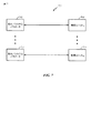
[0075] 図7は、上記の事象に基づくベイジアン推論および学習の実装例700を示す。図7において例示されるように、1つのメモリバンク702を計算ネットワーク(ニューラルネットワーク)の1つの処理ユニット704と直接インタフェースすることができる。各メモリバンク702は、変数(神経信号)、シナプス荷重、および/または対応する処理ユニット(ニューラルプロセッサ704に関連するシステムパラメータ、遅延、周波数ビン情報、ノード状態情報、バイアス重み情報、結合重み情報、および/または発火率情報を格納することができる。本開示の一態様において、処理ユニット704は、ノードにおいて入力事象を受信し、中間値を得るために入力事象にバイアス重みおよび結合重みを加え、中間値に基づいてノード状態を決定し、および、確率論的点過程により出力事象を生成するためにノード状態に基づいて事後確率を表す出力事象率を計算するように構成することができる。
[0076] 図8は、本開示の幾つかの態様によるニューラルネットワーク800の実装例を示す。図8において例示されるように、ニューラルネットワーク800は、ここにおいて説明される方法の様々な動作を実行することができる複数のローカル処理ユニット802を有することができる。各ローカル処理ユニット802は、ニューラルネットワークのパラメータを格納するローカル状態メモリ804とローカルパラメータメモリ806とを備えることができる。さらに、ローカル処理ユニット802は、ローカルモデルプログラムを格納するためのローカル(ニューロン)モデルプログラム(LMP)メモリ808、ローカル学習プログラムを格納するためのローカル学習プログラムを格納するためのローカル学習プログラム(LLP)メモリ810、およびローカル結合メモリ812を有することができる。さらに、図8において例示されるように、各ローカル処理ユニット802は、ローカル処理ユニットのローカルメモリに関する構成を提供するための構成プロセッサユニット814と、および、ローカル処理ユニット802間でのルーティングを提供するルーティングユニット816と、インタフェースすることができる。
[0077] 一構成において、ニューロンモデルは、ノードにおいて入力事象を受信し、中間値を得るために入力事象にバイアス重みおよび結合重みを加え、中間値に少なくとも部分的に基づいてノード状態を決定し、および、確率論的点過程により出力事象を生成するためにノード状態に基づいて事後確率を表す出力事象率を計算するように構成される。ニューロンモデルは、受信する手段と、加える手段と、決定する手段と、計算する手段と、を含む。一態様において、受信する手段、加える手段、決定する手段、および/または計算する手段は、示される機能を果たすように構成された汎用プロセッサ502、プログラムメモリ506、メモリブロック504、メモリ602、相互接続ネットワーク604、処理ユニット606、処理ユニット704、ローカル処理ユニット802、および/またはルーティング接続処理素子816であることができる。他の構成において、上記の手段は、上記の手段によって示される機能を果たすように構成されたいずれかのモジュールまたはいずれかの装置であることができる。
[0078] 本開示の幾つかの態様により、各ローカル処理ユニット802は、ニューラルネットワークの希望される1つ以上の機能上の特徴に基づいてニューラルネットワークのパラメータを決定し、および、決定されたパラメータがさらに好適化、チューニングおよび更新されるのに応じて希望される機能上の特徴に向けて1つ以上の機能上の特徴を発展させるように構成することができる。
[0079] 図9は、本開示の態様によるベイジアンネットワークを例示したブロック図900である。ベイジアンネットワークは、推理における確率変数の相互依存性の自然な表現を提供することができる。図9を参照し、ノードXおよびYが示される。ノードX(902)およびY(904)は、確率変数を備えることができ、および、XおよびYのある一定の相互依存性を有する有限の一組の状態の離散状態にあることができる。ノードおよびそれらの間での相互依存性は、幾つかの態様においては、スパイキングニューラルネットワークを介して表すことができる。例えば、スパイキングニューラルネットワークは、N個の観測可能な確率変数Y∈{1,...N}を受信することができる。本開示の態様により、観測された変数Yに関する遠因(underlying cause)X∈{1,...K}を決定することができる。
[0080] 図10は、本開示の幾つかの態様による事象に基づくベイジアン推論および学習を行うための例示的なアーキテクチャ1000を示したブロック図である。図10を参照し、入力事象ストリーム1002を受け取り、入力トレース(例えば、1006a乃至1006N)を生成するために使用することができる。入力事象ストリーム1002は、1本以上の(例えば、N本の)入力ラインを介して供給することができる。幾つかの態様において、入力ストリームは、入力の配列として構成することができる。例えば、配列の各入力、従って、各入力ライン、は、ディスプレイのピクセルに対応することができる。
[0081] 入力事象ストリーム1002は、スパイクまたはスパイク事象を備えることができる。入力事象ストリーム内の各スパイクまたはスパイク事象は、観測された変数Yのサンプルに対応することができる。幾つかの態様において、入力事象ストリーム1002は、例えば、時間の持続性(time persistence)を提供するためにフィルタ1004a乃至1004Nを介してフィルタリングすることができる。フィルタ1004a乃至1004Nは、例えば、方形パルスフィルタ、興奮性シナプス後電位(EPSP)フィルタ、またはいずれかのその他のフィルタであることができる。1つの例示的な態様において、フィルタ(例えば、1004a乃至1004N)は、以下のように表すことができる。
[0074] FIG. 6 is a block diagram of an
[0075] FIG. 7 shows an
[0076] FIG. 8 illustrates an example implementation of a
[0077] In one configuration, the neuron model receives an input event at a node, adds bias weights and coupling weights to the input event to obtain an intermediate value, and determines a node state based at least in part on the intermediate value. And an output event rate that represents the posterior probability based on the node state to generate an output event by a stochastic point process. The neuron model includes means for receiving, means for adding, means for determining, and means for calculating. In one aspect, the means for receiving, means for adding, means for determining, and / or means for calculating are
[0078] According to some aspects of the present disclosure, each
[0079] FIG. 9 is a block diagram 900 illustrating a Bayesian network according to aspects of the present disclosure. Bayesian networks can provide a natural representation of the interdependencies of random variables in reasoning. Referring to FIG. 9, nodes X and Y are shown. Nodes X (902) and Y (904) can comprise random variables and can be in a discrete state of a finite set of states with certain interdependencies of X and Y. The nodes and the interdependencies between them can be represented via a spiking neural network in some aspects. For example, a spiking neural network has N observable random variables Yε {1,. . . N} can be received. According to aspects of the present disclosure, an underlying cause X ∈ {1,. . . K} can be determined.
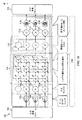
[0080] FIG. 10 is a block diagram illustrating an
[0081] The
ここで、εは、入力カーネル関数であり、tεは、入力カーネル関数のタイムサポート(time support)である。 Here, ε is an input kernel function, and t ε is a time support of the input kernel function.
[0082] 入力スパイク事象は、次のように、入力トレース1006a乃至1006Nを形成するためにフィルタ1004a乃至1004Nと畳み込んで積分することができる。 [0082] Input spike events can be convolved with filters 1004a through 1004N and integrated to form input traces 1006a through 1006N as follows.
ここで、ρnは、N個の観測が行われるy(n)のスパイク応答関数である。
[0083] バイアス重み(1008の最上行)および/または結合おもみ(1008の残りの行)は、重みが付けられた入力を形成するために入力トレース1006に加えることができる。バイアス項を指定してバイアス重みの各々に適用することができる。図10の例示的なアーキテクチャにおいて、バイアス項は1である(図15、要素1506を参照)。しかしながら、これは単に例示的であるにすぎず、設計上の選好に従って他のバイアス項に置き換えることができる。
[0084] 幾つかの態様において、バイアス重みおよび/または結合重み(1008)の各々は、対応する行内の入力トレース(例えば、1006a乃至1006N)に加えることができる。例えば、結合重みw1 1、w1 k、およびw1 Kを入力トレースu1に加えることができる。
[0085] ノード状態1010(例えば、v1、vk、およびvK)を決定するために各列内の重み付き入力を合計することができる。幾つかの態様において、ノード状態1010は、膜電位を備えることができる。ノード状態1010は、次のように表すことができる。
Here, ρ n is a spike response function of y (n) where N observations are made.
[0083] Bias weights (top row of 1008) and / or combined weights (remaining rows of 1008) can be added to
[0084] In some aspects, each of the bias weights and / or combination weights (1008) can be applied to input traces (eg, 1006a through 1006N) in the corresponding row. For example, joint weights w 1 1 , w 1 k , and w 1 K can be added to the input trace u 1 .
[0085] The weighted inputs in each column can be summed to determine the node state 1010 (eg, v 1 , v k , and v K ). In some aspects, the
ここで、kは、間隔であり、w0 kは、間隔kに関するバイアス重みである。 Here, k is an interval, and w 0 k is a bias weight for the interval k.
[0087] 幾つかの態様において、ノード状態は、例えば、ウィナー・テーク・オール(WTA)またはソフトWTA方式で正規化を用いて決定することができる。1つの例示的な態様において、ノード状態1010は、次の正規化式によって正規化することができる。
[0087] In some aspects, the node state may be determined using normalization, eg, in a winner take all (WTA) or soft WTA scheme. In one exemplary aspect, the
[0088]
ここで、λxは、平均合計発火率に対応する定数である。
[0089] ノード状態1010は、出力ノード(例えば、1012a、1012k、1012K)を介して出力事象ストリーム1016を生成するために確率論的過程(例えば、ポワソン過程)の対象となることができる。幾つかの態様において、確率論的過程または点過程は、出力事象率に対応する強度関数を備えることができる。出力事象率は、ノード状態1010に基づく事後確率を表すことができる。幾つかの態様において、出力事象率は、時間に基づいて計算することができる。代替として、幾つかの態様において、出力事象率は、事象に基づいて計算することができる。
[0090] 幾つかの態様において、出力ノード1012a乃至1012Kを介しての出力は、フィルタ1014a乃至1014Nを介してフィルタリングすることができる。1つの例示的な態様において、フィルタ1014a乃至1014Nは、デジタル出力を提供するためのデジタルフィルタを備えることができる。
[0091] 幾つかの態様において、ノードは、ニューロンであることができる。従って、出力事象ストリーム1016は、事後確率を表す出力発火率を有するスパイク事象であることができる。すなわち、ニューロンは、ニューロン状態(例えば、膜電位)の関数である発火の確率を有するスパイクを発火させることができる。例えば、出力ノード(例えば、1012a乃至1012K)(そして、従って、出力事象ストリーム)に関する発火率は以下によって与えることができる。
[0092]
[0088]
Here, λ x is a constant corresponding to the average total firing rate.
[0089] The
[0090] In some aspects, the output through
[0091] In some aspects, the node may be a neuron. Thus, the
[0092]
[0093] 幾つかの態様において、出力スパイク事象時間は、次のように出力発火率から計算することができる。
[0094]
[0093] In some aspects, the output spike event time can be calculated from the output firing rate as follows.
[0094]
ここで、ξ〜Exp(1)は、率パラメータ1を有する指数分布から導き出された乱数である。
Here, ξ to Exp (1) are random numbers derived from the exponential distribution having the
[0095] 幾つかの態様において、学習を実装するためにスパイクタイミング依存可塑性(STDP)規則を適用することができる。例えば、バイアス重みおよび/または結合重み(1008)の各々は、出力事象ストリーム1016(例えば、事後分布からの出力サンプル)に基づいて更新することができる。例えば、STDP規則は、次のように適用することができる。 [0095] In some aspects, spike timing dependent plasticity (STDP) rules can be applied to implement learning. For example, each of the bias weights and / or combination weights (1008) can be updated based on the output event stream 1016 (eg, output samples from the posterior distribution). For example, STDP rules can be applied as follows.
[0096]
[0097]
[0096]
[0097]
ここで、τ=r−1Δtおよびτ0=r0 −1Δtは、学習率rを制御し、c0は、定数である。 Here, τ = r −1 Δt and τ 0 = r 0 −1 Δt control the learning rate r, and c 0 is a constant.
[0098] 当然のことであるが、これは、単なる例示であるにすぎず、その他の学習則および/または学習モデルが学習を実装することができる。STDP学習則を用いることで、バイアスおよび/または結合重みを事象に基づいて更新することができる。例えば、幾つかの態様において、バイアスおよび/または結合重み1008は、スパイク事象が発生したときに更新することができる。
[0098] It will be appreciated that this is merely exemplary, and other learning rules and / or learning models may implement learning. By using STDP learning rules, bias and / or coupling weights can be updated based on events. For example, in some aspects, the bias and / or
[0099] 1つの例示的な態様において、アーキテクチャは、事象を検出するように動作させることができる。入力事象の場合は、入力トレース(例えば、入力トレース1006a乃至1006N)は、入力電流とみなすことができる受け取られた入力事象または事象(複数)に基づいて決定することができる。幾つかの態様において、入力電流は、例えば、受け取られた入力事象のタイミングに基づいて決定することができる入力事象オフセットに基づいて増減させることができる。 [0099] In one exemplary aspect, the architecture can be operated to detect events. For input events, input traces (eg, input traces 1006a-1006N) can be determined based on the received input event or events that can be considered as input current. In some aspects, the input current can be increased or decreased based on, for example, an input event offset that can be determined based on the timing of the received input event.
[00100] バイアス重みおよび/または結合重み1008は、入力電流に加えることができる。入力電流は、ニューロン状態1010を計算(または更新)するために合計することができる。次に、更新されたニューロン状態1010は、出力ニューロン1012a乃至1012Kに関する発火率を計算するために使用することができる。計算された発火率は、予想される出力事象タイミングを調整または更新することもできる。すなわち、出力ニューロン1012a乃至1012Kを介して出力される各事象またはスパイクに関して、更新された発火率に基づいて事象またはスパイクに関する予想されるタイミングを計算および更新することができる。予想される出力事象toutputの前のtinputの時点で入力事象が発生した場合は、ニューロンの瞬間的スパイクレートをλoldからλnewに変化させ、予想される出力事象時間を次のように更新することができる。
[00100] Bias weights and / or
[00102] 出力事象またはスパイクの場合、バイアス重みおよび/または結合重み(1008)は、例えば、上述されるSTDP規則を用いて更新することができる。これで、次の出力事象(例えば、スパイク)を推定することができる。 [00102] In the case of an output event or spike, the bias weight and / or the combined weight (1008) can be updated using, for example, the STDP rules described above. The next output event (eg, spike) can now be estimated.
[00103] このように、図9を参照し、Y(904)をサンプリングすることによって、X(902)の事前状態を推論することができる。さらに、Yの尤度が与えられている場合は、ある一定のXを与えることができる(例えば、出力ニューロンによって表すことができる)。 [00103] Thus, referring to FIG. 9, by sampling Y (904), the prior state of X (902) can be inferred. Furthermore, if a likelihood of Y is given, a certain X can be given (eg, can be represented by an output neuron).
[00104] 従って、例示的なアーキテクチャ1000を用いて数多くの用途を実現することができる。該用途は、パターン認識、空間的パターンの時間的系列の学習を含むことができ、ただし、パターン認識、空間的パターンの時間的系列の学習に限定されない。
[00104] Accordingly, a number of applications can be realized using the
[00105] 幾つかの態様において、図10のアーキテクチャは、モジュール化することができる。図11は、本開示の態様による事象に基づくベイジアン推論および学習を行うための例示的な推論エンジンモジュール1100を示したブロック図である。幾つかの態様において、推論エンジンモジュール1100の構成は、図10のアーキテクチャ1000のそれに対応することができる。
[00105] In some aspects, the architecture of FIG. 10 can be modularized. FIG. 11 is a block diagram illustrating an example
[00106] 図11を参照し、推論エンジンモジュール1100は、入力ブロック1102と、入力トレースブロック1006と、バイアスおよび結合重みブロック1008と、結合と、出力ブロック1110と、を含む。出力ブロックは、図10を参照して上述されるようにノード1010および1012a乃至1012Kを含むように構成することができる。推論エンジンモジュール1100は、より大型でより複雑なシステムを構築するために使用することができる。
Referring to FIG. 11,
[00107] 図12は、本開示の態様による事象に基づくベイジアン推論おび学習を行うためのモジュール1100を用いるアドレス事象表現(AER)センサのための例示的なアーキテクチャ1200を示したブロック図である。図12において示されるように、AERセンサ1202aおよび1202b(総じてAERセンサ1202と呼ばれる)は、事象をキャプチャすることができる。2つのAERセンサが示されているが、これは単なる例示であるにすぎず、1つ以上の入力を採用することができる。
[00107] FIG. 12 is a block diagram illustrating an
[00108] キャプチャされた事象は、フィーチャーモジュール(feature module)1204に供給することができる。フィーチャーモジュール1204は、図11の推論エンジンモジュール1100の形と同様のそれで構成および機能を有することができる。フィーチャーモジュール1204は、AERセンサ1202a−1202bから入力事象ストリームを受け取り、AERセンサ1202a−1202bの環境の観測されない特徴に対応する出力事象ストリームを生成することができる。観測されない特徴に関連する追加情報を決定するためにさらなる推論エンジンモジュール(例えば、1206a、1206b、および1206cであり、総じて推論エンジンモジュール1206と呼ぶことができる)を組み入れることができる。
[00108] The captured events can be provided to a
[00109] 一例において、AERセンサ1202a−1202bは、カメラを備えることができる。カメラは、例えば、ある所定の空間におけるオブジェクトの存在をキャプチャするように構成することができる。一例において、カメラは、所定の空間内のオブジェクトの位置に関する2D事象情報を提供することができる。フィーチャーモジュールの出力は、推論エンジンモジュール1206a、1206b、1206cに供給することができ、推論エンジンモジュール1206a、1206b、1206cは、所定の空間内のオブジェクトの3D座標の一部分を推論することができる。
[00109] In one example,
[00110] 推論エンジンモジュール1206a乃至1206cは、モジュール1206a乃至1206cの推論を向上させるためにスーパバイザ1208を介して訓練することができる。本例において、推論エンジンモジュール1206a乃至1206cの推論された座標(X、Y、Z)を、所定の空間内のオブジェクトの実際のまたは真の位置と比較することができる。幾つかの態様において、バイアスおよび/または結合重みは、モジュール1206a乃至1206cの各々からの推論の精度を向上させるために真の位置の情報に基づいて更新することができる。
[00110]
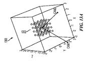
[00111] 図13Aは、空間1300を示し、空間内の幾つかの位置に配置された様々なオブジェクトを含む。カメラ(CAM1およびCAM2)は、ある所定の3D空間内のオブジェクトの存在を検出することができる。すなわち、幾つかの態様において、カメラによって所定の空間内においてオブジェクトが検出されたときには、カメラは、事象(例えば、スパイク事象)を生成することができる。図13Bおよび13Cにおいて、カメラ(例えば、CAM1およびCAM2)によって検出されたオブジェクト1302がそれぞれ示される。各々のカメラは、検出されたオブジェクト1302に対応する事象ストリームを生成することができる。図13Bおよび13Cにおいて示されるように、3Dオブジェクト1302の2D(例えば、xおよびy座標のみ)表現(1310および1320)が事象ストリーム内で表現される。従って、所定の空間内のオブジェクトの各々を正確に表現するために、第3の座標(例えば、z座標)を決定するのが有益であろう。
[00111] FIG. 13A shows a
[00112] 図12を参照し、AERセンサ1202aおよび1202bは、カメラ、例えば、図13のCAM1およびCAM2、を備えることができる。従って、カメラを介してキャプチャされた事象は、上述されるように事象に基づくベイジアン推論および学習を行うためのモジュール内に入力することができる。ベイジアン推論および学習のためのモジュール(例えば、推論エンジンモジュール1100)を用いて、図13Aにおいて示される所定の空間内のオブジェクトの位置(例えば、x、yおよびz座標)は、カメラ(例えば、CAM1およびCAM2)を介して提供された入力ストリームから決定することができる。
[00112] Referring to FIG. 12,
[00113] 例えば、CAM1およびCAM2は、各々、64×64入力(例えば、図13Bおよび13Cにおいて示される1302の表現)をフィーチャーモジュール1204に提供することができ、フィーチャーモジュール1204は、例えば、スパイキングニューラルネットワークの隠れ層を備えることができる。入力は、例えば、4×4格子に分割された空間内でカメラ(CAM1およびCAM2)が検知する物に基づくことができる。フィーチャーモジュール1204は、2つの64×64入力を64の3D空間出力に変換することができ、64の3D空間出力は、上述されるように推論および学習によって、推論エンジンモジュール1206a乃至206cによって受信される。推論エンジンモジュール1206a乃至206cは、上述されるように推論および学習によって、幾つかの座標、例えば、各次元において4つ、に出力を量子化することができる。このようにして、2D AERカメラ(例えば、図13のCAM1およびCAM2)のみを用いて3Dビジョンを実現することができる。各座標に関する64×64入力、64の特徴および4つの出力が説明されるが、本開示は、その数には限定されない。本3Dビジョン例においては、モジュールの各々でバイアス重みブロックは使用されない。
[00113] For example, CAM1 and CAM2 can each provide 64 × 64 inputs (eg, the representation of 1302 shown in FIGS. 13B and 13C) to
[00114] 幾つかの態様において、モジュールは、オブジェクトの真の位置(例えば、x、yおよびz座標)を訓練するためにスーパバイザ1208(例えば、SX、SYおよびSZ)を介して提供することができる実際のオブジェクト位置を用いて訓練することができる。推論エンジンモジュール1206a乃至206cが訓練された時点で、スーパバイザをディスエーブルにすることができ、推論エンジンモジュール1206a乃至206cは、スーパバイザ1208なしで操作することができる。
[00114] In some aspects, the module is provided via a supervisor 1208 (eg, S X , S Y and S Z ) to train the true position (eg, x, y and z coordinates) of the object. You can train with actual object positions that you can do. When the
[00115] 幾つかの態様において、事象に基づく推論および学習のためのアーキテクチャは、隠れマルコフモデルの学習のために構成することができる。マルコフモデルは、状態が非決定論的な方法で前の状態に依存するプロセスをモデル化する確率論的モデルである。隠れマルコフモデル(HMM)では、状態は、部分的のみに観測可能である。 [00115] In some aspects, an architecture for event-based reasoning and learning can be configured for learning a hidden Markov model. A Markov model is a probabilistic model that models processes whose states depend on previous states in a non-deterministic manner. In the Hidden Markov Model (HMM), the state is only partially observable.
[00116] 図14Aは、隠れマルコフモデルを例示した概略図1400である。図14Aを参照し、確率変数Xt∈{1,...,K}が隠されており、確率変数Yt∈{1,...,N}が可視である。{Xt}および{Yt}は、次の依存性を有する。
Xt→Yt 出力確率行列P(Yt=n|Xt=k)に基づく
Xt−1→Xt 遷移確率行列P(Yt=k|Xt−1=k’)に基づく
[00117] 出力確率は、ある特定の時間における隠れ変数(Xt)の状態が与えられている場合にその時間における観測された変数(Yt)の分布を決定する。他方、遷移確率は、時間t−1における隠された状態が与えられている場合に時間tにおける隠された状態をどのようにして選択することができるかを制御する。
[00118] 図14Bは、本開示の態様による隠れマルコフモデルに関する事象に基づく推論および学習のための例示的なアーキテクチャを示した高位ブロック図である。図14Bにおいて示されるように、アーキテクチャは、推論エンジンモジュール1452を含むことができ、推論エンジンモジュール1452は、理解および説明を容易にすることを目的として、Yをモジュール入力としておよびX^をモジュール出力として示す(X^は、Xの推定値である)。幾つかの態様において、YからX^への入力は瞬間的であることができる。X^出力は、フィードバック経路または反復結合1458を介してのモジュールへの入力であることもできる。フィードバック経路1458は、遅延が生じることがある。図14Bにおいて示されるように、遅延は、1つの期間であることができる。当然のことであるが、これは単なる例示であるにすぎず、限定するものではない。YからX^への結合は、バックワード結合(backward connection)であり、X^からのフィードバック結合1458は、フォワード結合(forward connection)であることが注目される。
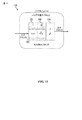
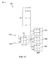
[00119] 図15は、本開示の態様による隠れマルコフモデルに関する事象に基づく推論および学習のための例示的なアーキテクチャ1500を示したブロック図である。図15を参照し、例示的なアーキテクチャ1500は、図10に関して上述されるコンポーネントに類似するコンポーネントを含む。
[00120] 入力事象ストリーム1502は、入力であり(図15の左上を参照)、入力トレース{un}(例えば、1506a、1506n、1506N)を生成するために使用することができる。ノード1510に関するノード状態を決定するためにバイアス重みおよび/または結合重みを入力トレースに加えて合計することができる。他方、ノード状態は、出力ノード1512a乃至1512Kに関する発火率を計算するためにおよび出力事象ストリーム1516を生成するために使用することができる。図14Bと同様に、出力事象ストリーム1516は、フィードバック経路1518を介して入力として供給することができる。
[00121] 幾つかの態様において、入力フィルタη(τ)を出力事象ストリーム1516に適用することができる。入力トレース{un}(例えば、1506a、1506n、1506N)は、図14Aにおいて示されるようにYからの入力に対応することができる。幾つかの態様において、結合重み{wm k}は、全体で、出力確率行列として働くことができる。幾つかの態様において、結合重み{wn k}は、以下によって与えることができる対数出力確率を備えることができる。
[00116] FIG. 14A is a schematic diagram 1400 illustrating a hidden Markov model. Referring to FIG. 14A, a random variable X t ε {1,. . . , K} are hidden and the random variable Y t ε {1,. . . , N} is visible. {X t } and {Y t } have the following dependencies:
Based on X t → Y t output probability matrix P (Y t = n | X t = k)
Based on X t−1 → X t transition probability matrix P (Y t = k | X t−1 = k ′)
[00117] The output probability determines the distribution of the observed variable (Y t ) at that time given the state of the hidden variable (X t ) at a particular time. On the other hand, the transition probability controls how the hidden state at time t can be selected given the hidden state at time t-1.
[00118] FIG. 14B is a high-level block diagram illustrating an exemplary architecture for event-based reasoning and learning for hidden Markov models according to aspects of the present disclosure. As shown in FIG. 14B, the architecture can include an
[00119] FIG. 15 is a block diagram illustrating an
[00120] The
[00121] In some aspects, an input filter η (τ) may be applied to the
ここで、Cは定数である。
[00122] 出力は、Xに対応することができ(図14A参照)、フィードバック経路1518を介して供給し、入力トレース{uk}(例えば、1506z、1506k、1506K)を生成するために使用することができる。幾つかの態様において、入力フィルタη(τ)(例えば、1504z、1504k、および1504K)は、ε(τ)の時間遅延バージョンとして構成することができ、従って、η(τ−1)=ε(τ)である。従って、入力トレース{uk}(例えば、1506z、1506k、1506K)は、入力トレース{un}(例えば、1506a、1506n、1506N)と対照的に1つの時間ステップだけ遅延されることがある。
[00123] 幾つかの態様において、結合重み{wkk’}(1508の最下部の3つの行)は、全体として、遷移確率行列として働くことができる。幾つかの態様において、結合重み{wkk’}は、以下によって与えることができる対数遷移確率を備えることができる。
Here, C is a constant.
[00122] The output can correspond to X (see FIG. 14A) and is fed through the feedback path 1518 and used to generate the input trace {u k } (eg, 1506z, 1506k, 1506K). be able to. In some aspects, the input filter η (τ) (eg, 1504z, 1504k, and 1504K) can be configured as a time-delayed version of ε (τ), and therefore η (τ-1) = ε ( τ). Thus, the input trace {u k } (eg, 1506z, 1506k, 1506K) may be delayed by one time step as opposed to the input trace {u n } (eg, 1506a, 1506n, 1506N).
[00123] In some aspects, the combined weights {w kk ′ } (the bottom three rows of 1508) can act as a transition probability matrix as a whole. In some aspects, the combination weight {w kk ′ } may comprise a log transition probability that may be given by:
ここで、Cは定数である。
[00124] このようにして、事象に基づく推論および学習のためのアーキテクチャは、隠れ変数の状態を決定するように構成することができ、従って、隠れマルコフモデルを解くために動作させることができる。
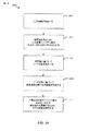
[00125] 図16は、本開示の態様による事象に基づくベイジアン推論および学習を行うための方法1600を例示する。ブロック1602において、プロセスは、ノードにおいて入力事象を受け取る。ノードは、ソフトウェアオブジェクト、ニューロン、ハードウェアモジュール、プロセッサで動作するソフトウェア、スパイキングニューラルネットワーク、等であることができる。
[00126] 幾つかの態様において、入力事象は、入力分布からのサンプルに対応することができる。さらに、幾つかの態様において、入力事象は、それらをパルスに変換するためにフィルタリングすることができる。例えば、入力事象は、方形パルスフィルタを用いてフィルタリングすることができる。
[00127] ブロック1604において、プロセスは、中間値を得るために入力事象にバイアス重みおよび結合重みを加える。ブロック1606において、プロセスは、中間値に基づいてノード状態を決定する。幾つかの態様において、ノード状態は、中間値を合計することによって決定することができる。
[00128] ブロック1608において、プロセスは、確率論的点過程により出力事象を生成するためにノード状態に基づいて事後確率を表す出力事象率を計算する。
[00129] さらに、ブロック1610において、プロセスは、対数尤度を表すバイアス重みおよび/または結合重みを更新するためにSTDP規則を適用する。幾つかの態様において、バイアス重みは、事後確率に対応することができ、結合重みは、対数尤度を表すことができる。
[00130] 幾つかの態様において、プロセスは、隠れマルコフモデルをさらに解くことができる。例えば、プロセスは、追加の入力事象を提供するためのフィードバックとして出力事象を供給することをさらに含むことができる。プロセスは、第2の組の中間値を得るために追加の入力事象に第2の組の結合重みを加えることを含むこともできる。プロセスは、ノード状態および中間値の第2の組に基づいて隠れノード状態を計算することをさらに含むことができる。幾つかの態様において、追加の入力事象は、追加の入力事象が時間的に遅延されるようにするためにフィルタリングすることができる。
[00131] 上述される方法の様々な動作は、対応する機能を実行することが可能なあらゆる適切な手段によって行うことができる。手段は、様々なハードウェアおよび/またはソフトウェアコンポーネントおよび/またはモジュールを含むことができ、回路、特定用途向け集積回路(ASIC)、またはプロセッサを含み、ただし、回路、特定用途向け集積回路(ASIC)、またはプロセッサに限定されない。概して、図において例示される動作が存在する場合は、それらの動作は、同様の数字を有する対応する手段プラス機能(means−plus−function)コンポーネントを有することができる。
[00132] ここで使用される場合において、用語“決定する”は、非常に様々な行動を包含する。例えば、“決定する”は、計算すること、演算すること、処理すること、導き出すこと、調査すること、検索すること(例えば、テーブル、データベース又は他のデータ構造における検索)、確認すること、等を含むことができる。さらに、“決定する”は、受信すること(例えば、情報を受信する)、アクセスすること(例えば、メモリ内のデータにアクセス)、等を含むことができる。さらに、“決定する”は、解決すること、選抜すること、選択すること、確立すること、等を含むことができる。
[00133] ここで使用されるばあいにおいて、項目のリストのうちの“少なくとも1つの”を指す句は、それらの項目のあらゆる組み合わせを意味し、単数を含む。一例として、“a、b、またはcのうちの少なくとも1つの”は、a、b、c、a−b、a−c、b−c、およびa−b−cを網羅することが意図される。
[00134] 本開示と関係させて説明される様々な例示的な論理ブロック、モジュール、および回路は、ここにおいて説明される機能を果たすように設計された汎用プロセッサ、デジタル信号プロセッサ(DSP)、特定用途向け集積回路(ASIC)、フィールドプログラマブルゲートアレイ信号(FPGA)、その他のプログラマブル論理デバイス、ディスクリートゲートロジック、ディスクリートトランジスタロジック、ディスクリートハードウェアコンポーネント、又はそれらのあらゆる組合せ、を用いて実装又は実行することが可能である。汎用プロセッサはマイクロプロセッサであることができるが、代替においては、プロセッサは、市販のどのようなプロセッサ、コントローラ、マイクロコントローラ、又はステートマシンであってもよい。プロセッサは、コンピューティングデバイスの組合せ、例えば、DSPと、1つのマイクロプロセッサとの組合せ、複数のマイクロプロセッサとの組合せ、DSPコアと関連する1つ以上のマイクロプロセッサとの組合せ、又はあらゆるその他の構成、として実装することもできる。
[00135] 本開示と関係させて説明される方法又はアルゴリズムのステップは、直接ハードウェア内において、プロセッサによって実行されるソフトウェアモジュール内において、又はそれらの2つの組み合わせ内において具現化することができる。ソフトウェアモジュールは、当業界において知られるあらゆる形態の記憶媒体において常駐することができる。使用することができる記憶媒体の幾つかの例は、ランダムアクセスメモリ(RAM)、読み取り専用メモリ(ROM)、フラッシュメモリ、消去可能プログラマブル読み取り専用メモリ(EPROM)、電気的消去可能プログラマブル読み取り専用メモリ(EEPROM(登録商標))、レジスタ、ハードディスク、取り外し可能なディスク、CD−ROM、等を含む。ソフトウェアモジュールは、単一の命令、または数多くの命令を備えることができ、および、幾つかの異なるコードセグメントにわたって、異なるプログラム間で、および複数の記憶媒体にわたって分散させることができる。記憶媒体は、プロセッサが記憶媒体から情報を読み出すこと及び記憶媒体に情報を書き込むことができるような形でプロセッサに結合することができる。代替においては、記憶媒体は、プロセッサと一体化することができる。
[00136] ここにおいて開示される方法は、説明される方法を達成するための1つ以上のステップまたは行動を備える。方法のステップおよび/または行動は、請求項の範囲から逸脱することなしに互換可能である。換言すると、ステップまたは行動の特定の順序が指定されないかぎり、特定のステップおよび/または行動の順序および/または使用は、請求項の範囲から逸脱せずに変更することができる。
[00137] ここにおいて説明される機能は、ハードウェア、ソフトウェア、ファームウェア、またはそれらのいずれかの組み合わせにおいて実装することができる。ハードウェアにおいて実装される場合は、ハードウェア構成例は、デバイス内の処理システムを備えることができる。処理システムは、バスアーキテクチャで実装することができる。バスは、処理システムの特定の用途および全体的なシステム上の制約事項に依存してあらゆる数の相互接続バスおよびブリッジを含むことができる。バスは、プロセッサと、機械読み取り可能媒体と、バスインタフェースと、を含む様々な回路をひとつにリンクすることができる。バスインタフェースは、とりわけ、バスを介して処理システムにネットワークアダプタを接続するために使用することができる。ネットワークアダプタは、信号処理機能を実装するために使用することができる。幾つかの態様に関して、ユーザインタフェース(例えば、キーパッド、ディスプレイ、マウス、ジョイスティック、等)もバスに接続することができる。バスは、様々なその他の回路、例えば、タイミングソース、周辺機器、電圧調整器、電力管理回路、等、もひとつにリンクすることができ、それらは当業者界においてよく知られており、従って、これ以上は説明されない。
[00138] プロセッサは、バスおよび一般的な処理を管理するのを担当することができ、機械読み取り可能媒体に格納されたソフトウェアの実行を含む。プロセッサは、1つ以上の汎用および/または専用プロセッサとともに実装することができる。例は、マイクロプロセッサと、マイクロコントローラと、DSPプロセッサと、ソフトウェアを実行することができるその他の回路と、を含む。ソフトウェアとは、命令、データ、またはそれらのあらゆる組み合わせ
を意味すると広義で解釈するものとし、ソフトウェア、ファームウェア、ミドルウェア、マイクロコード、ハードウェア記述言語、またはその他のいずれとして呼ばれるかを問わない。機械読み取り可能媒体は、例として、ランダムアクセスメモリ(RAM)、フラッシュメモリ、読み取り専用メモリ(ROM)、プログラマブル読み取り専用メモリ(PROM)、消去可能プログラマブル読み取り専用メモリ(EPROM)、電気的消去可能プログラマブル読み取り専用メモリ(EEPROM)、レジスタ、磁気ディスク、光ディスク、ハードドライブ、またはあらゆるその他の適切な記憶媒体、またはそれらのあらゆる組み合わせを含むことができる。機械読み取り可能媒体は、コンピュータプログラム製品において具現化することができる。コンピュータプログラム製品は、パッケージング材料を備えることができる。
Here, C is a constant.
[00124] In this way, the architecture for event-based reasoning and learning can be configured to determine the state of hidden variables and can therefore be operated to solve hidden Markov models.
[00125] FIG. 16 illustrates a
[00126] In some embodiments, the input event can correspond to a sample from the input distribution. Further, in some aspects, input events can be filtered to convert them to pulses. For example, input events can be filtered using a square pulse filter.
[00127] At
[00128] At
[00129] Further, at
[00130] In some aspects, the process can further solve a hidden Markov model. For example, the process can further include providing an output event as feedback to provide an additional input event. The process may also include adding a second set of coupling weights to the additional input events to obtain a second set of intermediate values. The process can further include calculating a hidden node state based on the second set of node states and intermediate values. In some aspects, additional input events can be filtered to ensure that additional input events are delayed in time.
[00131] The various operations of the methods described above can be performed by any suitable means capable of performing the corresponding function. The means can include various hardware and / or software components and / or modules, including a circuit, application specific integrated circuit (ASIC), or processor, provided that the circuit, application specific integrated circuit (ASIC). Or a processor. In general, if there are operations illustrated in the figures, those operations may have corresponding means-plus-function components having similar numbers.
[00132] As used herein, the term "determining" encompasses a wide variety of actions. For example, “determining” means calculating, computing, processing, deriving, exploring, searching (eg, searching in a table, database or other data structure), checking, etc. Can be included. Further, “determining” can include receiving (eg, receiving information), accessing (eg, accessing data in a memory) and the like. Further, “determining” can include resolving, selecting, selecting, establishing, and the like.
[00133] As used herein, the phrase "at least one" in a list of items means any combination of those items and includes the singular. By way of example, “at least one of a, b, or c” is intended to cover a, b, c, a-b, a-c, bc, and a-b-c. The
[00134] Various exemplary logic blocks, modules, and circuits described in connection with this disclosure are general purpose processors, digital signal processors (DSPs), specific, designed to perform the functions described herein. Implementation or implementation using application specific integrated circuits (ASICs), field programmable gate array signals (FPGAs), other programmable logic devices, discrete gate logic, discrete transistor logic, discrete hardware components, or any combination thereof Is possible. A general purpose processor may be a microprocessor, but in the alternative, the processor may be any commercially available processor, controller, microcontroller or state machine. A processor may be a combination of computing devices, eg, a combination of a DSP and a microprocessor, a combination of multiple microprocessors, a combination of one or more microprocessors associated with a DSP core, or any other configuration Can also be implemented.
[00135] The method or algorithm steps described in connection with the present disclosure may be embodied directly in hardware, in a software module executed by a processor, or in a combination of the two. A software module may reside in any form of storage medium that is known in the art. Some examples of storage media that can be used are random access memory (RAM), read only memory (ROM), flash memory, erasable programmable read only memory (EPROM), electrically erasable programmable read only memory ( EEPROM (registered trademark)), register, hard disk, removable disk, CD-ROM, and the like. A software module can comprise a single instruction, or many instructions, and can be distributed across several different code segments, between different programs, and across multiple storage media. A storage medium may be coupled to the processor such that the processor can read information from, and write information to, the storage medium. In the alternative, the storage medium may be integral to the processor.
[00136] The methods disclosed herein comprise one or more steps or actions for achieving the described method. The method steps and / or actions may be interchanged without departing from the scope of the claims. In other words, unless a specific order of steps or actions is specified, the order and / or use of specific steps and / or actions may be changed without departing from the scope of the claims.
[00137] The functions described herein may be implemented in hardware, software, firmware, or any combination thereof. If implemented in hardware, the example hardware configuration may comprise a processing system in the device. The processing system can be implemented with a bus architecture. The bus can include any number of interconnecting buses and bridges depending on the particular application of the processing system and overall system constraints. The bus can link together various circuits including a processor, a machine readable medium, and a bus interface. The bus interface can be used, among other things, to connect a network adapter to the processing system via the bus. Network adapters can be used to implement signal processing functions. For some aspects, a user interface (eg, keypad, display, mouse, joystick, etc.) can also be connected to the bus. The bus can also be linked to various other circuits, such as timing sources, peripherals, voltage regulators, power management circuits, etc., which are well known in the art and thus No further explanation will be given.
[00138] The processor may be responsible for managing the bus and general processing, including the execution of software stored on a machine-readable medium. A processor can be implemented with one or more general purpose and / or dedicated processors. Examples include a microprocessor, a microcontroller, a DSP processor, and other circuitry that can execute software. Software shall be interpreted broadly to mean instructions, data, or any combination thereof, whether referred to as software, firmware, middleware, microcode, hardware description language, or any other. Machine-readable media include, for example, random access memory (RAM), flash memory, read-only memory (ROM), programmable read-only memory (PROM), erasable programmable read-only memory (EPROM), electrically erasable programmable read It may include dedicated memory (EEPROM), registers, magnetic disk, optical disk, hard drive, or any other suitable storage medium, or any combination thereof. A machine-readable medium may be embodied in a computer program product. The computer program product can comprise packaging material.
[00139] ハードウェア実装において、機械読み取り可能媒体は、プロセッサから分離された処理システムの一部であることができる。しかしながら、当業者が容易に認識するように、機械読み取り可能媒体、またはそれのいずれかの部分は、処理システムの外部に存在することができる。例として、機械読み取り可能媒体は、送信ライン、データによって変調されるキャリア、および/またはデバイスから分離されたコンピュータ製品を含むことができ、それらのすべては、バスインタフェースを通じてプロセッサによってアクセスすることができる。代替として、またはさらに加えて、機械読み取り可能媒体、またはそれのいずれかの部分は、キャッシュおよび/または汎用レジスタファイルの場合のように、プロセッサと一体化することができる。論じられる様々なコンポーネント、例えば、ローカルコンポーネント、は、特定の場所を有するとして説明することができるが、それらは、様々な形で構成することもでき、例えば、幾つかのコンポーネントは、分散型コンピューティングシステムの一部として構成される。 [00139] In a hardware implementation, the machine-readable medium may be part of a processing system that is separate from the processor. However, as those skilled in the art will readily recognize, the machine-readable medium, or any portion thereof, can be external to the processing system. By way of example, a machine-readable medium can include a transmission line, a carrier modulated with data, and / or a computer product separated from a device, all of which can be accessed by a processor through a bus interface. . Alternatively or additionally, the machine-readable medium, or any portion thereof, may be integrated with the processor, as in the case of caches and / or general purpose register files. Although the various components discussed, e.g., local components, can be described as having a particular location, they can also be configured in various ways, e.g., some components are distributed computing. Configured as part of an operating system.
[00140] 処理システムは、プロセッサ機能を提供する1つ以上のマイクロプロセッサおよび機械読み取り可能媒体の少なくとも一部分を提供する外部メモリを有する汎用処理システムとして構成することができ、すべては、外部のバスアーキテクチャを通じてその他の支援回路とひとつにリンクされる。代替として、処理システムは、ここにおいて説明されるニューロンモデルおよびニューラルシステムモデルを実装するための1つ以上の神経形態学的プロセッサを備えることができる。他の代替として、処理システムは、プロセッサ、バスインタフェース、ユーザインタフェース、支援回路、および単一のチップ内に組み入れられた機械読み取り可能媒体の少なくとも一部分を有する特定用途向け集積回路(ASIC)とともに、または、1つ以上のフィールドプログラマブルゲートアレイ(FPGA)、プログラマブルロジックデバイス(PLD)、コントローラ、ステートマシン、ゲーテッド(gated)ロジック、ディスクリートハードウェアコンポーネント、または、この開示全体を通じて説明される様々な機能を実行することができる回路のあらゆる組み合わせとともに、実装することができる。当業者は、特定の用途および全体的なシステムに対して課せられた全体的な設計上の制約事項に依存して処理システムに関する説明される機能を実装するための最良の方法を認識するであろう。 [00140] The processing system can be configured as a general purpose processing system having one or more microprocessors that provide processor functionality and an external memory that provides at least a portion of the machine-readable medium, all of which are external bus architectures. And linked to other supporting circuits through Alternatively, the processing system can comprise one or more neuromorphological processors for implementing the neuron model and neural system model described herein. As another alternative, the processing system may include a processor, a bus interface, a user interface, support circuitry, and an application specific integrated circuit (ASIC) having at least a portion of a machine readable medium incorporated in a single chip, or One or more field programmable gate arrays (FPGAs), programmable logic devices (PLDs), controllers, state machines, gated logic, discrete hardware components, or perform various functions described throughout this disclosure It can be implemented with any combination of circuits that can. Those skilled in the art will recognize the best way to implement the described functionality for a processing system depending on the specific application and the overall design constraints imposed on the overall system. Let's go.
[00141] 機械読み取り可能媒体は、幾つかのソフトウェアモジュールを備えることができる。ソフトウェアモジュールは、プロセッサによって実行されたときに、様々な機能を実行することを処理システムに行わせる命令を含む。ソフトウェアモジュールは、送信モジュールと、受信モジュールと、を含むことができる。各ソフトウェアモジュールは、単一の記憶デバイス内に常駐することまたは複数の記憶デバイスにわたって分散させることができる。例として、ソフトウェアモジュールは、トリガリング事象が発生したときにハードドライブからRAM内にロードすることができる。ソフトウェアモジュールの実行中には、プロセッサは、アクセス速度を上げるために命令の一部をキャッシュ内にロードすることができる。次に、1つ以上のキャッシュラインをプロセッサによる実行のために一般的レジスタファイル内にロードすることができる。以下のソフトウェアモジュールの機能を参照するときに、該機能は、そのソフトウェアモジュールからの命令を実行するときにプロセッサによって実装される。 [00141] A machine-readable medium may comprise a number of software modules. A software module includes instructions that, when executed by a processor, cause the processing system to perform various functions. The software module can include a transmission module and a reception module. Each software module can reside within a single storage device or can be distributed across multiple storage devices. As an example, a software module can be loaded into RAM from a hard drive when a triggering event occurs. During execution of the software module, the processor can load some of the instructions into the cache to increase access speed. One or more cache lines can then be loaded into a general register file for execution by the processor. When referring to the function of a software module below, the function is implemented by the processor when executing instructions from that software module.
[00142] ソフトウェアにおいて実装される場合は、これらの機能は、コンピュータ読み取り可能媒体において1つ以上の命令またはコードとして格納することまたは送信することができる。コンピュータ読み取り可能媒体は、コンピュータ記憶媒体と、1つの場所から他へのコンピュータプログラムの転送を容易にするあらゆる媒体を含む通信媒体と、の両方を含む。記憶媒体は、コンピュータによってアクセス可能なあらゆる利用可能な媒体であることができる。一例として、および限定することなしに、該コンピュータ読み取り可能媒体は、RAM、ROM、EEPROM、CD−ROM又はその他の光学ディスク記憶装置、磁気ディスク記憶装置またはその他の磁気記憶デバイス、または、希望されるプログラムコードを命令またはデータ構造の形態で搬送または格納するために用いることができおよびコンピュータによってアクセス可能なその他の媒体、を備えることができる。さらに、いずれの接続も、コンピュータ読み取り可能媒体であると適切に呼ばれる。例えば、ソフトウェアが、同軸ケーブル、光ファイバケーブル、より対線、デジタル加入者ライン(DSL)、又は無線技術、例えば、赤外線、無線、及びマイクロ波、を用いてウェブサイト、サーバ、又はその他の遠隔ソースから送信される場合は、その同軸ケーブル、光ファイバケーブル、より対線、DSL、または無線技術、例えば赤外線、無線、及びマイクロ波、は、媒体の定義の中に含まれる。ここにおいて用いられるときのディスク(disk及びdisc)は、コンパクトディスク(CD)(disc)と、レーザーディスク(登録商標)(disc)と、光ディスク(disc)と、デジタルバーサタイルディスク(DVD)(disc)と、フロッピー(登録商標)ディスク(disk)と、ブルーレイディスク(disc)と、を含み、ここで、diskは通常は磁気的にデータを複製し、discは、レーザを用いて光学的にデータを複製する。従って、幾つかの態様において、コンピュータ読み取り可能媒体は、非一時的なコンピュータ読み取り可能媒体(例えば、有形の媒体)を備えることができる。さらに、その他の態様に関して、コンピュータ読み取り可能媒体は、一時的なコンピュータ読み取り可能媒体(例えば、信号)を備えることができる。上記の組み合わせも、コンピュータ読み取り可能媒体の適用範囲内に含められるべきである。 [00142] When implemented in software, the functions may be stored on or transmitted over as one or more instructions or code on a computer-readable medium. Computer-readable media includes both computer storage media and communication media including any medium that facilitates transfer of a computer program from one place to another. A storage media may be any available media that can be accessed by a computer. By way of example and not limitation, the computer-readable medium may be RAM, ROM, EEPROM, CD-ROM or other optical disk storage, magnetic disk storage or other magnetic storage device, or desired Any other medium that can be used to carry or store program code in the form of instructions or data structures and that is accessible by a computer can be provided. In addition, any connection is properly referred to as a computer-readable medium. For example, the software uses a coaxial cable, fiber optic cable, twisted pair, digital subscriber line (DSL), or wireless technology, eg, infrared, wireless, and microwave, to a website, server, or other remote When transmitted from a source, its coaxial cable, fiber optic cable, twisted pair, DSL, or wireless technologies such as infrared, wireless, and microwave are included in the definition of the medium. As used herein, the discs (disk and disc) are a compact disc (CD) (disc), a laser disc (registered trademark) (disc), an optical disc (disc), and a digital versatile disc (DVD) (disc). And a floppy disk (disk) and a Blu-ray disk (disk), where the disk normally replicates data magnetically, and the disk optically uses a laser to replicate data. Duplicate. Thus, in some aspects computer readable media may comprise non-transitory computer readable media (eg, tangible media). Moreover, with respect to other aspects, the computer-readable medium can comprise a transitory computer-readable medium (eg, a signal). Combinations of the above should also be included within the scope of computer-readable media.
[00143] 従って、幾つかの態様は、ここにおいて提示される動作を行うためのコンピュータプログラム製品を備えることができる。例えば、該コンピュータプログラム製品は、命令が格納されている(および/または符号化されている)コンピュータ読み取り可能媒体を備えることができ、命令は、ここにおいて説明される動作を行うために1つ以上のプロセッサによって実行可能である。幾つかの態様に関して、コンピュータプログラム製品は、パッケージング材料を含むことができる。 [00143] Accordingly, some aspects may comprise a computer program product for performing the operations presented herein. For example, the computer program product can comprise a computer-readable medium having instructions stored (and / or encoded) with one or more instructions to perform the operations described herein. Can be executed by other processors. For some aspects, the computer program product may include packaging material.
[00144] さらに、ここにおいて説明される方法および技法を実行するためのモジュールおよび/またはその他の該当する手段は、ユーザ端末および/または基地局によって適宜ダウンロードすることおよび/または別の方法で入手することができることが認識されるべきである。例えば、該デバイスは、ここにおいて説明される方法を実行するための手段の移動を容易にするためにサーバに結合することができる。代替として、ここにおいて説明される様々な方法は、記憶手段(例えば、RAM、ROM、物理的記憶媒体、例えば、コンパクトディスク(CD)またはフロッピーディスク、等)を介して提供することができ、従って、ユーザ端末および/または基地局は、デバイスに記憶手段を結合または提供した時点で様々な方法を入手することができる。さらに、ここにおいて説明される方法および技法をデバイスに提供するためのあらゆるその他の適切な技法を利用することができる。 [00144] Further, modules and / or other appropriate means for performing the methods and techniques described herein may be downloaded and / or otherwise obtained as appropriate by user terminals and / or base stations. It should be recognized that it can. For example, the device can be coupled to a server to facilitate movement of means for performing the methods described herein. Alternatively, the various methods described herein can be provided via storage means (eg, RAM, ROM, physical storage media such as a compact disk (CD) or floppy disk, etc.), and thus The user terminal and / or base station can obtain various methods at the time of coupling or providing storage means to the device. In addition, any other suitable technique for providing the devices with the methods and techniques described herein may be utilized.
[00145] 請求項は、上記の正確な構成およびコンポーネントに限定されないことが理解されるべきである。請求項の範囲から逸脱することなしに上述される方法および装置の配置、動作、および詳細の様々な修正、変更および変形を行うことができる。 [00145] It is to be understood that the claims are not limited to the precise configuration and components illustrated above. Various modifications, changes and variations in the arrangement, operation and details of the methods and apparatus described above may be made without departing from the scope of the claims.
[0073] 図5は、本開示の幾つかの態様による汎用プロセッサ502を用いた上記の事象に基づくベイジアン推論および学習の実装例500を示す。メモリブロック504には変数(神経信号)、シナプス荷重、計算ネットワーク(ニューラルネットワーク)に関連するシステムパラメータ、遅延、周波数ビン情報、ノード状態情報、バイアス重み情報、結合重み情報、および/または発火率情報を格納することができ、他方、汎用プロセッサ502で実行される命令は、プログラムメモリ506からロードすることができる。本開示の一態様において、汎用プロセッサ502にロードされた命令は、ノードにおいて入力事象を受信し、中間値を得るために入力事象にバイアス重みおよび結合重みを加え、中間値に基づいてノード状態を決定し、および、確率論的点過程により出力事象を生成するためにノード状態に基づいて事後確率を表す出力事象率を計算するためのコードを備えることができる。
[0073] FIG. 5 illustrates an
ここで、Cは定数である。
[00122] 出力は、Xに対応することができ(図14A参照)、フィードバック経路1518を介して供給し、入力トレース{uk}(例えば、1506z、1506k、1506K)を生成するために使用することができる。幾つかの態様において、入力フィルタη(τ)(例えば、1504z、1504k、および1504K)は、出力事象ストリーム1516に適用されることができる。入力フィルタη(τ)(例えば、1504z、1504k、および1504K)は、ε(τ)の時間遅延バージョンとして構成することができ、従って、η(τ−1)=ε(τ)である。従って、入力トレース{uk}(例えば、1506z、1506k、1506K)は、入力トレース{un}(例えば、1506a、1506n、1506N)と対照的に1つの時間ステップだけ遅延されることがある。
[00123] 幾つかの態様において、結合重み{wkk’}(1508の最下部の3つの行)は、全体として、遷移確率行列として働くことができる。幾つかの態様において、結合重み{wkk’}は、以下によって与えることができる対数遷移確率を備えることができる。
Here, C is a constant.
[00122] The output can correspond to X (see FIG. 14A) and is fed through the feedback path 1518 and used to generate the input trace {u k } (eg, 1506z, 1506k, 1506K). be able to. In some aspects, an input filter η (τ) (eg, 1504z, 1504k, and 1504K) may be applied to the
[00123] In some aspects, the combined weights {w kk ′ } (the bottom three rows of 1508) can act as a transition probability matrix as a whole. In some aspects, the combination weight {w kk ′ } may comprise a log transition probability that may be given by:
ここで、Cは定数である。
[00124] このようにして、事象に基づく推論および学習のためのアーキテクチャは、隠れ変数の状態を決定するように構成することができ、従って、隠れマルコフモデルを解くために動作させることができる。
[00125] 図16は、本開示の態様による事象に基づくベイジアン推論および学習を行うための方法1600を例示する。ブロック1602において、プロセスは、ノードにおいて入力事象を受け取る。ノードは、ソフトウェアオブジェクト、ニューロン、ハードウェアモジュール、プロセッサで動作するソフトウェア、スパイキングニューラルネットワーク、等であることができる。
[00126] 幾つかの態様において、入力事象は、入力分布からのサンプルに対応することができる。さらに、幾つかの態様において、入力事象は、それらをパルスに変換するためにフィルタリングすることができる。例えば、入力事象は、方形パルスフィルタを用いてフィルタリングすることができる。
[00127] ブロック1604において、プロセスは、中間値を得るために入力事象にバイアス重みおよび結合重みを加える。ブロック1606において、プロセスは、中間値に基づいてノード状態を決定する。幾つかの態様において、ノード状態は、中間値を合計することによって決定することができる。
[00128] ブロック1608において、プロセスは、確率論的点過程により出力事象を生成するためにノード状態に基づいて事後確率を表す出力事象率を計算する。
[00129] さらに、ブロック1610において、プロセスは、対数尤度を表すバイアス重みおよび/または結合重みを更新するためにSTDP規則を適用する。幾つかの態様において、バイアス重みは、事前確率に対応することができ、結合重みは、対数尤度を表すことができる。
[00130] 幾つかの態様において、プロセスは、隠れマルコフモデルをさらに解くことができる。例えば、プロセスは、追加の入力事象を提供するためのフィードバックとして出力事象を供給することをさらに含むことができる。プロセスは、第2の組の中間値を得るために追加の入力事象に第2の組の結合重みを加えることを含むこともできる。プロセスは、ノード状態および中間値の第2の組に基づいて隠れノード状態を計算することをさらに含むことができる。幾つかの態様において、追加の入力事象は、追加の入力事象が時間的に遅延されるようにするためにフィルタリングすることができる。
[00131] 上述される方法の様々な動作は、対応する機能を実行することが可能なあらゆる適切な手段によって行うことができる。手段は、様々なハードウェアおよび/またはソフトウェアコンポーネントおよび/またはモジュールを含むことができ、回路、特定用途向け集積回路(ASIC)、またはプロセッサを含み、ただし、回路、特定用途向け集積回路(ASIC)、またはプロセッサに限定されない。概して、図において例示される動作が存在する場合は、それらの動作は、同様の数字を有する対応する手段プラス機能(means−plus−function)コンポーネントを有することができる。
[00132] ここで使用される場合において、用語“決定する”は、非常に様々な行動を包含する。例えば、“決定する”は、計算すること、演算すること、処理すること、導き出すこと、調査すること、検索すること(例えば、テーブル、データベース又は他のデータ構造における検索)、確認すること、等を含むことができる。さらに、“決定する”は、受信すること(例えば、情報を受信する)、アクセスすること(例えば、メモリ内のデータにアクセス)、等を含むことができる。さらに、“決定する”は、解決すること、選抜すること、選択すること、確立すること、等を含むことができる。
[00133] ここで使用されるばあいにおいて、項目のリストのうちの“少なくとも1つの”を指す句は、それらの項目のあらゆる組み合わせを意味し、単数を含む。一例として、“a、b、またはcのうちの少なくとも1つの”は、a、b、c、a−b、a−c、b−c、およびa−b−cを網羅することが意図される。
[00134] 本開示と関係させて説明される様々な例示的な論理ブロック、モジュール、および回路は、ここにおいて説明される機能を果たすように設計された汎用プロセッサ、デジタル信号プロセッサ(DSP)、特定用途向け集積回路(ASIC)、フィールドプログラマブルゲートアレイ信号(FPGA)、その他のプログラマブル論理デバイス、ディスクリートゲートロジック、ディスクリートトランジスタロジック、ディスクリートハードウェアコンポーネント、又はそれらのあらゆる組合せ、を用いて実装又は実行することが可能である。汎用プロセッサはマイクロプロセッサであることができるが、代替においては、プロセッサは、市販のどのようなプロセッサ、コントローラ、マイクロコントローラ、又はステートマシンであってもよい。プロセッサは、コンピューティングデバイスの組合せ、例えば、DSPと、1つのマイクロプロセッサとの組合せ、複数のマイクロプロセッサとの組合せ、DSPコアと関連する1つ以上のマイクロプロセッサとの組合せ、又はあらゆるその他の構成、として実装することもできる。
[00135] 本開示と関係させて説明される方法又はアルゴリズムのステップは、直接ハードウェア内において、プロセッサによって実行されるソフトウェアモジュール内において、又はそれらの2つの組み合わせ内において具現化することができる。ソフトウェアモジュールは、当業界において知られるあらゆる形態の記憶媒体において常駐することができる。使用することができる記憶媒体の幾つかの例は、ランダムアクセスメモリ(RAM)、読み取り専用メモリ(ROM)、フラッシュメモリ、消去可能プログラマブル読み取り専用メモリ(EPROM)、電気的消去可能プログラマブル読み取り専用メモリ(EEPROM(登録商標))、レジスタ、ハードディスク、取り外し可能なディスク、CD−ROM、等を含む。ソフトウェアモジュールは、単一の命令、または数多くの命令を備えることができ、および、幾つかの異なるコードセグメントにわたって、異なるプログラム間で、および複数の記憶媒体にわたって分散させることができる。記憶媒体は、プロセッサが記憶媒体から情報を読み出すこと及び記憶媒体に情報を書き込むことができるような形でプロセッサに結合することができる。代替においては、記憶媒体は、プロセッサと一体化することができる。
[00136] ここにおいて開示される方法は、説明される方法を達成するための1つ以上のステップまたは行動を備える。方法のステップおよび/または行動は、請求項の範囲から逸脱することなしに互換可能である。換言すると、ステップまたは行動の特定の順序が指定されないかぎり、特定のステップおよび/または行動の順序および/または使用は、請求項の範囲から逸脱せずに変更することができる。
[00137] ここにおいて説明される機能は、ハードウェア、ソフトウェア、ファームウェア、またはそれらのいずれかの組み合わせにおいて実装することができる。ハードウェアにおいて実装される場合は、ハードウェア構成例は、デバイス内の処理システムを備えることができる。処理システムは、バスアーキテクチャで実装することができる。バスは、処理システムの特定の用途および全体的なシステム上の制約事項に依存してあらゆる数の相互接続バスおよびブリッジを含むことができる。バスは、プロセッサと、機械読み取り可能媒体と、バスインタフェースと、を含む様々な回路をひとつにリンクすることができる。バスインタフェースは、とりわけ、バスを介して処理システムにネットワークアダプタを接続するために使用することができる。ネットワークアダプタは、信号処理機能を実装するために使用することができる。幾つかの態様に関して、ユーザインタフェース(例えば、キーパッド、ディスプレイ、マウス、ジョイスティック、等)もバスに接続することができる。バスは、様々なその他の回路、例えば、タイミングソース、周辺機器、電圧調整器、電力管理回路、等、もひとつにリンクすることができ、それらは当業者界においてよく知られており、従って、これ以上は説明されない。
[00138] プロセッサは、バスおよび一般的な処理を管理するのを担当することができ、機械読み取り可能媒体に格納されたソフトウェアの実行を含む。プロセッサは、1つ以上の汎用および/または専用プロセッサとともに実装することができる。例は、マイクロプロセッサと、マイクロコントローラと、DSPプロセッサと、ソフトウェアを実行することができるその他の回路と、を含む。ソフトウェアとは、命令、データ、またはそれらのあらゆる組み合わせを意味すると広義で解釈するものとし、ソフトウェア、ファームウェア、ミドルウェア、マイクロコード、ハードウェア記述言語、またはその他のいずれとして呼ばれるかを問わない。機械読み取り可能媒体は、例として、ランダムアクセスメモリ(RAM)、フラッシュメモリ、読み取り専用メモリ(ROM)、プログラマブル読み取り専用メモリ(PROM)、消去可能プログラマブル読み取り専用メモリ(EPROM)、電気的消去可能プログラマブル読み取り専用メモリ(EEPROM)、レジスタ、磁気ディスク、光ディスク、ハードドライブ、またはあらゆるその他の適切な記憶媒体、またはそれらのあらゆる組み合わせを含むことができる。機械読み取り可能媒体は、コンピュータプログラム製品において具現化することができる。コンピュータプログラム製品は、パッケージング材料を備えることができる。
Here, C is a constant.
[00124] In this way, the architecture for event-based reasoning and learning can be configured to determine the state of hidden variables and can therefore be operated to solve hidden Markov models.
[00125] FIG. 16 illustrates a
[00126] In some embodiments, the input event can correspond to a sample from the input distribution. Further, in some aspects, input events can be filtered to convert them to pulses. For example, input events can be filtered using a square pulse filter.
[00127] At
[00128] At
[00129] Further, at
[00130] In some aspects, the process can further solve a hidden Markov model. For example, the process can further include providing an output event as feedback to provide an additional input event. The process may also include adding a second set of coupling weights to the additional input events to obtain a second set of intermediate values. The process can further include calculating a hidden node state based on the second set of node states and intermediate values. In some aspects, additional input events can be filtered to ensure that additional input events are delayed in time.
[00131] The various operations of the methods described above can be performed by any suitable means capable of performing the corresponding function. The means can include various hardware and / or software components and / or modules, including a circuit, application specific integrated circuit (ASIC), or processor, provided that the circuit, application specific integrated circuit (ASIC). Or a processor. In general, if there are operations illustrated in the figures, those operations may have corresponding means-plus-function components having similar numbers.
[00132] As used herein, the term "determining" encompasses a wide variety of actions. For example, “determining” means calculating, computing, processing, deriving, exploring, searching (eg, searching in a table, database or other data structure), checking, etc. Can be included. Further, “determining” can include receiving (eg, receiving information), accessing (eg, accessing data in a memory) and the like. Further, “determining” can include resolving, selecting, selecting, establishing, and the like.
[00133] As used herein, the phrase "at least one" in a list of items means any combination of those items and includes the singular. By way of example, “at least one of a, b, or c” is intended to cover a, b, c, a-b, a-c, bc, and a-b-c. The
[00134] Various exemplary logic blocks, modules, and circuits described in connection with this disclosure are general purpose processors, digital signal processors (DSPs), specific, designed to perform the functions described herein. Implementation or implementation using application specific integrated circuits (ASICs), field programmable gate array signals (FPGAs), other programmable logic devices, discrete gate logic, discrete transistor logic, discrete hardware components, or any combination thereof Is possible. A general purpose processor may be a microprocessor, but in the alternative, the processor may be any commercially available processor, controller, microcontroller or state machine. A processor may be a combination of computing devices, eg, a combination of a DSP and a microprocessor, a combination of multiple microprocessors, a combination of one or more microprocessors associated with a DSP core, or any other configuration Can also be implemented.
[00135] The method or algorithm steps described in connection with the present disclosure may be embodied directly in hardware, in a software module executed by a processor, or in a combination of the two. A software module may reside in any form of storage medium that is known in the art. Some examples of storage media that can be used are random access memory (RAM), read only memory (ROM), flash memory, erasable programmable read only memory (EPROM), electrically erasable programmable read only memory ( EEPROM (registered trademark)), register, hard disk, removable disk, CD-ROM, and the like. A software module can comprise a single instruction, or many instructions, and can be distributed across several different code segments, between different programs, and across multiple storage media. A storage medium may be coupled to the processor such that the processor can read information from, and write information to, the storage medium. In the alternative, the storage medium may be integral to the processor.
[00136] The methods disclosed herein comprise one or more steps or actions for achieving the described method. The method steps and / or actions may be interchanged without departing from the scope of the claims. In other words, unless a specific order of steps or actions is specified, the order and / or use of specific steps and / or actions may be changed without departing from the scope of the claims.
[00137] The functions described herein may be implemented in hardware, software, firmware, or any combination thereof. If implemented in hardware, the example hardware configuration may comprise a processing system in the device. The processing system can be implemented with a bus architecture. The bus can include any number of interconnecting buses and bridges depending on the particular application of the processing system and overall system constraints. The bus can link together various circuits including a processor, a machine readable medium, and a bus interface. The bus interface can be used, among other things, to connect a network adapter to the processing system via the bus. Network adapters can be used to implement signal processing functions. For some aspects, a user interface (eg, keypad, display, mouse, joystick, etc.) can also be connected to the bus. The bus can also be linked to various other circuits, such as timing sources, peripherals, voltage regulators, power management circuits, etc., which are well known in the art and thus No further explanation will be given.
[00138] The processor may be responsible for managing the bus and general processing, including the execution of software stored on a machine-readable medium. A processor can be implemented with one or more general purpose and / or dedicated processors. Examples include a microprocessor, a microcontroller, a DSP processor, and other circuitry that can execute software. Software shall be interpreted broadly to mean instructions, data, or any combination thereof, whether referred to as software, firmware, middleware, microcode, hardware description language, or any other. Machine-readable media include, for example, random access memory (RAM), flash memory, read-only memory (ROM), programmable read-only memory (PROM), erasable programmable read-only memory (EPROM), electrically erasable programmable read It may include dedicated memory (EEPROM), registers, magnetic disk, optical disk, hard drive, or any other suitable storage medium, or any combination thereof. A machine-readable medium may be embodied in a computer program product. The computer program product can comprise packaging material.
[00145] 請求項は、上記の正確な構成およびコンポーネントに限定されないことが理解されるべきである。請求項の範囲から逸脱することなしに上述される方法および装置の配置、動作、および詳細の様々な修正、変更および変形を行うことができる。
以下に本願発明の当初の特許請求の範囲に記載された発明を付記する。
[C1]
事象に基づくベイジアン推論および学習を行う方法であって、
複数のノードのうちの各々において入力事象を受信することと、
中間値を得るために前記入力事象にバイアス重みおよび/または結合重みを加えることと、
前記中間値に少なくとも部分的に基づいてノード状態を決定することと、
確率論的点過程により出力事象を生成するために前記ノード状態に少なくとも部分的に基づいて事後確率を表す出力事象率を計算することと、を備える、方法。
[C2]
前記入力事象をパルスに変換するために前記入力事象をフィルタリングすることをさらに備える、
C1に記載の方法。
[C3]
前記入力事象は、入力分布からのサンプルに対応する、
C1に記載の方法。
[C4]
前記バイアス重みは、事前確率に対応し、前記結合重みは、対数尤度を表す、
C1に記載の方法。
[C5]
前記ノードは、正規化される、
C1に記載の方法。
[C6]
前記ノードは、ニューロンを備える、
C1に記載の方法。
[C7]
前記入力事象は、スパイクトレーンを備え、前記出力事象率は、発火率を備える、
C1に記載の方法。
[C8]
前記点過程は、前記出力事象率に対応する強度関数を備える、
C1に記載の方法。
[C9]
前記計算することは、時間に基づいて行われる、
C1に記載の方法。
[C10]
前記計算することは、事象に基づいて行われる、
C1に記載の方法。
[C11]
前記決定することは、前記ノード状態を形成するために前記中間値を合計することを備える、
C1に記載の方法。
[C12]
前記入力事象は、定義された空間における三次元(3D)オブジェクトの二次元(2D)表現を備え、前記出力事象は、前記定義された空間における前記3Dオブジェクトの第3の座標を備える、
C1に記載の方法。
[C13]
前記入力事象は、少なくとも1つのセンサから供給される、
C12に記載の方法。
[C14]
前記少なくとも1つのセンサは、アドレス事象表現カメラである、
C13に記載の方法。
[C15]
追加の入力事象を提供するためのフィードバックとして前記出力事象を供給することと、
第2の組の中間値を得るために前記追加の入力事象に第2の組の結合重みを加えることと、
前記ノード状態および前記第2の組の中間値に少なくとも部分的に基づいて少なくとも1つの隠れノード状態を計算することと、をさらに備える、
C1に記載の方法。
[C16]
前記追加の入力事象が時間遅延されるように前記追加の入力事象をフィルタリングすることをさらに備える、
C15に記載の方法。
[C17]
前記結合重みは、出力確率行列を備え、前記第2の組の結合重みは、遷移確率行列を備える、
C15に記載の方法。
[C18]
事象に基づくベイジアン推論および学習を行うための装置であって、
メモリと、
前記メモリに結合された少なくとも1つのプロセッサを備え、前記少なくとも1つのプロセッサは、
複数のノードのうちの各々において入力事象を受信し、
中間値を得るために前記入力事象にバイアス重みおよび/または結合重みを加え、
前記中間値に少なくとも部分的に基づいてノード状態を決定し、および
確率論的点過程により出力事象を生成するために前記ノード状態に少なくとも部分的に基づいて事後確率を表す出力事象率を計算するように構成される、装置。
[C19]
前記少なくとも1つのプロセッサは、前記入力事象をパルスに変換するために前記入力事象をフィルタリングするようにさらに構成される、
C18に記載の装置。
[C20]
前記入力事象は、スパイクトレーンを備え、前記出力事象率は、発火率を備える、
C18に記載の装置。
[C21]
前記少なくとも1つのプロセッサは、時間に基づいて前記出力事象率を計算するようにさらに構成される、
C18に記載の装置。
[C22]
前記少なくとも1つのプロセッサは、事象に基づいて前記出力事象率を計算するようにさらに構成される、
C18に記載の装置。
[C23]
前記少なくとも1つのプロセッサは、前記ノード状態を形成するために前記中間値を合計することによって前記ノード状態を決定するようにさらに構成される、
C18に記載の装置。
[C24]
前記入力事象は、定義された空間における三次元(3D)オブジェクトの二次元(2D)表現を備え、前記出力事象は、前記定義された空間における前記3Dオブジェクトの第3の座標を備える、
C18に記載の装置。
[C25]
前記入力事象を供給するための少なくとも1つのセンサをさらに備える、
C24に記載の装置。
[C26]
前記少なくとも1つのプロセッサは、追加の入力事象を提供するためのフィードバックとして前記出力事象を供給し、
第2の組の中間値を得るために前記追加の入力事象に第2の組の結合重みを加え、および
前記ノード状態および前記第2の組の中間値に少なくとも部分的に基づいて少なくとも1つの隠れノード状態を計算するようにさらに構成される、
C18に記載の装置。
[C27]
前記少なくとも1つのプロセッサは、前記追加の入力事象が時間遅延されるように前記追加の入力事象をフィルタリングするようにさらに構成される、
C26に記載の装置。
[C28]
前記結合重みは、出力確率行列を備え、前記第2の組の結合重みは、遷移確率行列を備える、
C27に記載の装置。
[C29]
事象に基づくベイジアン推論および学習を行うための装置であって、
複数のノードのうちの各々において入力事象を受信するための手段と、
中間値を得るために前記入力事象にバイアス重みおよび/または結合重みを加えるための手段と、
前記中間値に少なくとも部分的に基づいてノード状態を決定するための手段と、
確率論的点過程により出力事象を生成するために前記ノード状態に少なくとも部分的に基づいて事後確率を表す出力事象率を計算するための手段と、を備える、装置。
[C30]
事象に基づくベイジアン推論および学習を行うためのコンピュータプログラム製品であって、
プログラムコードを符号化した非一時的なコンピュータ読み取り可能媒体を備え、前記プログラムコードは、
複数のノードのうちの各々において入力事象を受信するためのプログラムコードと、
中間値を得るために前記入力事象にバイアス重みおよび/または結合重みを加えるためのプログラムコードと、
前記中間値に少なくとも部分的に基づいてノード状態を決定するためのプログラムコードと、
確率論的点過程により出力事象を生成するために前記ノード状態に少なくとも部分的に基づいて事後確率を表す出力事象率を計算するためのプログラムコードと、を備える、コンピュータプログラム製品。
[00145] It is to be understood that the claims are not limited to the precise configuration and components illustrated above. Various modifications, changes and variations in the arrangement, operation and details of the methods and apparatus described above may be made without departing from the scope of the claims.
The invention described in the scope of the claims of the present invention is appended below.
[C1]
A method for event-based Bayesian inference and learning, comprising:
Receiving an input event at each of a plurality of nodes;
Adding bias weights and / or joint weights to the input event to obtain an intermediate value;
Determining a node state based at least in part on the intermediate value;
Calculating an output event rate representative of a posterior probability based at least in part on the node state to generate an output event by a probabilistic point process.
[C2]
Further comprising filtering the input event to convert the input event into a pulse;
The method according to C1.
[C3]
The input event corresponds to a sample from the input distribution;
The method according to C1.
[C4]
The bias weight corresponds to a prior probability, and the combination weight represents a log likelihood.
The method according to C1.
[C5]
The node is normalized,
The method according to C1.
[C6]
The node comprises a neuron;
The method according to C1.
[C7]
The input event comprises a spike train and the output event rate comprises a firing rate;
The method according to C1.
[C8]
The point process comprises an intensity function corresponding to the output event rate;
The method according to C1.
[C9]
The calculating is performed based on time.
The method according to C1.
[C10]
The calculating is based on an event;
The method according to C1.
[C11]
The determining comprises summing the intermediate values to form the node state;
The method according to C1.
[C12]
The input event comprises a two-dimensional (2D) representation of a three-dimensional (3D) object in a defined space, and the output event comprises a third coordinate of the 3D object in the defined space;
The method according to C1.
[C13]
The input event is supplied from at least one sensor;
The method according to C12.
[C14]
The at least one sensor is an address event representation camera;
The method according to C13.
[C15]
Providing the output event as feedback to provide an additional input event;
Adding a second set of coupling weights to the additional input event to obtain a second set of intermediate values;
Calculating at least one hidden node state based at least in part on the node state and the second set of intermediate values;
The method according to C1.
[C16]
Further filtering the additional input event such that the additional input event is time delayed.
The method according to C15.
[C17]
The joint weight comprises an output probability matrix, and the second set of joint weights comprises a transition probability matrix;
The method according to C15.
[C18]
An apparatus for performing event-based Bayesian inference and learning comprising:
Memory,
At least one processor coupled to the memory, the at least one processor comprising:
Receiving an input event at each of a plurality of nodes;
Adding bias weights and / or joint weights to the input event to obtain an intermediate value;
Determining a node state based at least in part on the intermediate value; and
An apparatus configured to calculate an output event rate representing a posterior probability based at least in part on the node state to generate an output event by a probabilistic point process.
[C19]
The at least one processor is further configured to filter the input event to convert the input event to a pulse;
The apparatus according to C18.
[C20]
The input event comprises a spike train and the output event rate comprises a firing rate;
The apparatus according to C18.
[C21]
The at least one processor is further configured to calculate the output event rate based on time;
The apparatus according to C18.
[C22]
The at least one processor is further configured to calculate the output event rate based on an event;
The apparatus according to C18.
[C23]
The at least one processor is further configured to determine the node state by summing the intermediate values to form the node state;
The apparatus according to C18.
[C24]
The input event comprises a two-dimensional (2D) representation of a three-dimensional (3D) object in a defined space, and the output event comprises a third coordinate of the 3D object in the defined space;
The apparatus according to C18.
[C25]
Further comprising at least one sensor for providing the input event;
The device according to C24.
[C26]
The at least one processor provides the output event as feedback to provide an additional input event;
Adding a second set of coupling weights to the additional input event to obtain a second set of intermediate values; and
Further configured to calculate at least one hidden node state based at least in part on the node state and the second set of intermediate values;
The apparatus according to C18.
[C27]
The at least one processor is further configured to filter the additional input event such that the additional input event is time delayed.
The device according to C26.
[C28]
The joint weight comprises an output probability matrix, and the second set of joint weights comprises a transition probability matrix;
The device according to C27.
[C29]
An apparatus for performing event-based Bayesian inference and learning comprising:
Means for receiving an input event at each of a plurality of nodes;
Means for adding bias weights and / or joint weights to the input event to obtain an intermediate value;
Means for determining a node state based at least in part on the intermediate value;
Means for calculating an output event rate representative of a posteriori probability based at least in part on the node state to generate an output event by a probabilistic point process.
[C30]
A computer program product for performing event-based Bayesian inference and learning, comprising:
A non-transitory computer readable medium encoded with the program code, the program code comprising:
Program code for receiving an input event at each of a plurality of nodes;
Program code for adding bias weights and / or coupling weights to the input event to obtain an intermediate value;
Program code for determining a node state based at least in part on the intermediate value;
Computer program product comprising: program code for calculating an output event rate representative of a posteriori probability based at least in part on the node state to generate an output event by a probabilistic point process.
Claims (30)
複数のノードのうちの各々において入力事象を受信することと、
中間値を得るために前記入力事象にバイアス重みおよび/または結合重みを加えることと、
前記中間値に少なくとも部分的に基づいてノード状態を決定することと、
確率論的点過程により出力事象を生成するために前記ノード状態に少なくとも部分的に基づいて事後確率を表す出力事象率を計算することと、を備える、方法。 A method for event-based Bayesian inference and learning, comprising:
Receiving an input event at each of a plurality of nodes;
Adding bias weights and / or joint weights to the input event to obtain an intermediate value;
Determining a node state based at least in part on the intermediate value;
Calculating an output event rate representative of a posterior probability based at least in part on the node state to generate an output event by a probabilistic point process.
請求項1に記載の方法。 Further comprising filtering the input event to convert the input event into a pulse;
The method of claim 1.
請求項1に記載の方法。 The input event corresponds to a sample from the input distribution;
The method of claim 1.
請求項1に記載の方法。 The bias weight corresponds to a prior probability, and the combination weight represents a log likelihood.
The method of claim 1.
請求項1に記載の方法。 The node is normalized,
The method of claim 1.
請求項1に記載の方法。 The node comprises a neuron;
The method of claim 1.
請求項1に記載の方法。 The input event comprises a spike train and the output event rate comprises a firing rate;
The method of claim 1.
請求項1に記載の方法。 The point process comprises an intensity function corresponding to the output event rate;
The method of claim 1.
請求項1に記載の方法。 The calculating is performed based on time.
The method of claim 1.
請求項1に記載の方法。 The calculating is based on an event;
The method of claim 1.
請求項1に記載の方法。 The determining comprises summing the intermediate values to form the node state;
The method of claim 1.
請求項1に記載の方法。 The input event comprises a two-dimensional (2D) representation of a three-dimensional (3D) object in a defined space, and the output event comprises a third coordinate of the 3D object in the defined space;
The method of claim 1.
請求項12に記載の方法。 The input event is supplied from at least one sensor;
The method of claim 12.
請求項13に記載の方法。 The at least one sensor is an address event representation camera;
The method of claim 13.
第2の組の中間値を得るために前記追加の入力事象に第2の組の結合重みを加えることと、
前記ノード状態および前記第2の組の中間値に少なくとも部分的に基づいて少なくとも1つの隠れノード状態を計算することと、をさらに備える、
請求項1に記載の方法。 Providing the output event as feedback to provide an additional input event;
Adding a second set of coupling weights to the additional input event to obtain a second set of intermediate values;
Calculating at least one hidden node state based at least in part on the node state and the second set of intermediate values;
The method of claim 1.
請求項15に記載の方法。 Further filtering the additional input event such that the additional input event is time delayed.
The method of claim 15.
請求項15に記載の方法。 The joint weight comprises an output probability matrix, and the second set of joint weights comprises a transition probability matrix;
The method of claim 15.
メモリと、
前記メモリに結合された少なくとも1つのプロセッサを備え、前記少なくとも1つのプロセッサは、
複数のノードのうちの各々において入力事象を受信し、
中間値を得るために前記入力事象にバイアス重みおよび/または結合重みを加え、
前記中間値に少なくとも部分的に基づいてノード状態を決定し、および
確率論的点過程により出力事象を生成するために前記ノード状態に少なくとも部分的に基づいて事後確率を表す出力事象率を計算するように構成される、装置。 An apparatus for performing event-based Bayesian inference and learning comprising:
Memory,
At least one processor coupled to the memory, the at least one processor comprising:
Receiving an input event at each of a plurality of nodes;
Adding bias weights and / or joint weights to the input event to obtain an intermediate value;
Determining a node state based at least in part on the intermediate value, and calculating an output event rate representing a posterior probability based at least in part on the node state to generate an output event by a stochastic point process Configured as an apparatus.
請求項18に記載の装置。 The at least one processor is further configured to filter the input event to convert the input event to a pulse;
The apparatus according to claim 18.
請求項18に記載の装置。 The input event comprises a spike train and the output event rate comprises a firing rate;
The apparatus according to claim 18.
請求項18に記載の装置。 The at least one processor is further configured to calculate the output event rate based on time;
The apparatus according to claim 18.
請求項18に記載の装置。 The at least one processor is further configured to calculate the output event rate based on an event;
The apparatus according to claim 18.
請求項18に記載の装置。 The at least one processor is further configured to determine the node state by summing the intermediate values to form the node state;
The apparatus according to claim 18.
請求項18に記載の装置。 The input event comprises a two-dimensional (2D) representation of a three-dimensional (3D) object in a defined space, and the output event comprises a third coordinate of the 3D object in the defined space;
The apparatus according to claim 18.
請求項24に記載の装置。 Further comprising at least one sensor for providing the input event;
25. The device according to claim 24.
第2の組の中間値を得るために前記追加の入力事象に第2の組の結合重みを加え、および
前記ノード状態および前記第2の組の中間値に少なくとも部分的に基づいて少なくとも1つの隠れノード状態を計算するようにさらに構成される、
請求項18に記載の装置。 The at least one processor provides the output event as feedback to provide an additional input event;
Adding a second set of combined weights to the additional input event to obtain a second set of intermediate values, and at least one based on the node state and the second set of intermediate values Further configured to compute a hidden node state,
The apparatus according to claim 18.
請求項26に記載の装置。 The at least one processor is further configured to filter the additional input event such that the additional input event is time delayed.
27. Apparatus according to claim 26.
請求項27に記載の装置。 The joint weight comprises an output probability matrix, and the second set of joint weights comprises a transition probability matrix;
28. The device of claim 27.
複数のノードのうちの各々において入力事象を受信するための手段と、
中間値を得るために前記入力事象にバイアス重みおよび/または結合重みを加えるための手段と、
前記中間値に少なくとも部分的に基づいてノード状態を決定するための手段と、
確率論的点過程により出力事象を生成するために前記ノード状態に少なくとも部分的に基づいて事後確率を表す出力事象率を計算するための手段と、を備える、装置。 An apparatus for performing event-based Bayesian inference and learning comprising:
Means for receiving an input event at each of a plurality of nodes;
Means for adding bias weights and / or joint weights to the input event to obtain an intermediate value;
Means for determining a node state based at least in part on the intermediate value;
Means for calculating an output event rate representative of a posterior probability based at least in part on the node state to generate an output event by a probabilistic point process.
プログラムコードを符号化した非一時的なコンピュータ読み取り可能媒体を備え、前記プログラムコードは、
複数のノードのうちの各々において入力事象を受信するためのプログラムコードと、
中間値を得るために前記入力事象にバイアス重みおよび/または結合重みを加えるためのプログラムコードと、
前記中間値に少なくとも部分的に基づいてノード状態を決定するためのプログラムコードと、
確率論的点過程により出力事象を生成するために前記ノード状態に少なくとも部分的に基づいて事後確率を表す出力事象率を計算するためのプログラムコードと、を備える、コンピュータプログラム製品。 A computer program product for performing event-based Bayesian inference and learning, comprising:
A non-transitory computer readable medium encoded with the program code, the program code comprising:
Program code for receiving an input event at each of a plurality of nodes;
Program code for adding bias weights and / or coupling weights to the input event to obtain an intermediate value;
Program code for determining a node state based at least in part on the intermediate value;
Computer program product comprising: program code for calculating an output event rate representative of a posteriori probability based at least in part on the node state to generate an output event by a probabilistic point process.
Applications Claiming Priority (7)
| Application Number | Priority Date | Filing Date | Title |
|---|---|---|---|
| US201461943147P | 2014-02-21 | 2014-02-21 | |
| US61/943,147 | 2014-02-21 | ||
| US201461949154P | 2014-03-06 | 2014-03-06 | |
| US61/949,154 | 2014-03-06 | ||
| US14/281,220 | 2014-05-19 | ||
| US14/281,220 US20150242745A1 (en) | 2014-02-21 | 2014-05-19 | Event-based inference and learning for stochastic spiking bayesian networks |
| PCT/US2015/016665 WO2015127110A2 (en) | 2014-02-21 | 2015-02-19 | Event-based inference and learning for stochastic spiking bayesian networks |
Publications (2)
| Publication Number | Publication Date |
|---|---|
| JP2017509978A true JP2017509978A (en) | 2017-04-06 |
| JP2017509978A5 JP2017509978A5 (en) | 2018-03-08 |
Family
ID=52627570
Family Applications (1)
| Application Number | Title | Priority Date | Filing Date |
|---|---|---|---|
| JP2016553286A Pending JP2017509978A (en) | 2014-02-21 | 2015-02-19 | Event-based reasoning and learning for stochastic spiking Bayesian networks |
Country Status (8)
| Country | Link |
|---|---|
| US (1) | US20150242745A1 (en) |
| EP (1) | EP3108410A2 (en) |
| JP (1) | JP2017509978A (en) |
| KR (1) | KR20160123309A (en) |
| CN (1) | CN106030620B (en) |
| CA (1) | CA2937949A1 (en) |
| TW (1) | TW201541374A (en) |
| WO (1) | WO2015127110A2 (en) |
Families Citing this family (17)
| Publication number | Priority date | Publication date | Assignee | Title |
|---|---|---|---|---|
| US10635968B2 (en) * | 2016-03-24 | 2020-04-28 | Intel Corporation | Technologies for memory management of neural networks with sparse connectivity |
| US11222278B2 (en) | 2016-09-08 | 2022-01-11 | Fujitsu Limited | Estimating conditional probabilities |
| US10108538B1 (en) * | 2017-07-31 | 2018-10-23 | Google Llc | Accessing prologue and epilogue data |
| EP3756144A4 (en) * | 2018-02-23 | 2022-06-22 | INTEL Corporation | Method, device and system to generate a bayesian inference with a spiking neural network |
| US11521053B2 (en) * | 2018-04-17 | 2022-12-06 | Hrl Laboratories, Llc | Network composition module for a bayesian neuromorphic compiler |
| US11288572B2 (en) * | 2018-04-17 | 2022-03-29 | Hrl Laboratories, Llc | Programming model for a bayesian neuromorphic compiler |
| CN108647725A (en) * | 2018-05-11 | 2018-10-12 | 国家计算机网络与信息安全管理中心 | A kind of neuron circuit for realizing static Hidden Markov Model reasoning |
| DE102018127383A1 (en) * | 2018-11-02 | 2020-05-07 | Universität Bremen | Data processing device with an artificial neural network and method for data processing |
| US20210397936A1 (en) * | 2018-11-13 | 2021-12-23 | The Board Of Trustees Of The University Of Illinois | Integrated memory system for high performance bayesian and classical inference of neural networks |
| EP3935574A1 (en) * | 2019-03-05 | 2022-01-12 | HRL Laboratories, LLC | Network -composition. module for a bayesian neuromorphic compiler |
| US11201893B2 (en) | 2019-10-08 | 2021-12-14 | The Boeing Company | Systems and methods for performing cybersecurity risk assessments |
| CN110956256B (en) * | 2019-12-09 | 2022-05-17 | 清华大学 | Method and device for realizing Bayes neural network by using memristor intrinsic noise |
| KR102535635B1 (en) * | 2020-11-26 | 2023-05-23 | 광운대학교 산학협력단 | Neuromorphic computing device |
| KR102595095B1 (en) * | 2020-11-26 | 2023-10-27 | 서울대학교산학협력단 | Toddler-inspired bayesian learning method and computing apparatus for performing the same |
| CN113191402B (en) * | 2021-04-14 | 2022-05-20 | 华中科技大学 | Memristor-based naive Bayes classifier design method, system and classifier |
| CN113516172B (en) * | 2021-05-19 | 2023-05-12 | 电子科技大学 | Image classification method based on Bayesian neural network error injection by random calculation |
| US20240095354A1 (en) * | 2022-09-14 | 2024-03-21 | Worcester Polytechnic Institute | Assurance model for an autonomous robotic system |
Family Cites Families (5)
| Publication number | Priority date | Publication date | Assignee | Title |
|---|---|---|---|---|
| US8943008B2 (en) * | 2011-09-21 | 2015-01-27 | Brain Corporation | Apparatus and methods for reinforcement learning in artificial neural networks |
| US9111224B2 (en) * | 2011-10-19 | 2015-08-18 | Qualcomm Incorporated | Method and apparatus for neural learning of natural multi-spike trains in spiking neural networks |
| US9111225B2 (en) * | 2012-02-08 | 2015-08-18 | Qualcomm Incorporated | Methods and apparatus for spiking neural computation |
| US9367797B2 (en) * | 2012-02-08 | 2016-06-14 | Jason Frank Hunzinger | Methods and apparatus for spiking neural computation |
| US20130204814A1 (en) * | 2012-02-08 | 2013-08-08 | Qualcomm Incorporated | Methods and apparatus for spiking neural computation |
-
2014
- 2014-05-19 US US14/281,220 patent/US20150242745A1/en not_active Abandoned
-
2015
- 2015-02-19 JP JP2016553286A patent/JP2017509978A/en active Pending
- 2015-02-19 EP EP15708074.8A patent/EP3108410A2/en not_active Withdrawn
- 2015-02-19 WO PCT/US2015/016665 patent/WO2015127110A2/en active Application Filing
- 2015-02-19 KR KR1020167022921A patent/KR20160123309A/en unknown
- 2015-02-19 CA CA2937949A patent/CA2937949A1/en not_active Abandoned
- 2015-02-19 CN CN201580009313.6A patent/CN106030620B/en active Active
- 2015-02-24 TW TW104105879A patent/TW201541374A/en unknown
Non-Patent Citations (1)
| Title |
|---|
| BERNHARD NESSLER ET AL.: "Bayesian Computation Emerges in Generic Cortical Microcircuits through Spike-Timing-Dependent Plast", PLOS COMPUTATIONAL BIOLOGY, vol. Volume 9, Issue 4, e1003037, JPN6019006825, 25 April 2013 (2013-04-25), pages pp. 1-30 * |
Also Published As
| Publication number | Publication date |
|---|---|
| WO2015127110A2 (en) | 2015-08-27 |
| TW201541374A (en) | 2015-11-01 |
| EP3108410A2 (en) | 2016-12-28 |
| US20150242745A1 (en) | 2015-08-27 |
| KR20160123309A (en) | 2016-10-25 |
| CN106030620B (en) | 2019-04-16 |
| CA2937949A1 (en) | 2015-08-27 |
| WO2015127110A3 (en) | 2015-12-03 |
| CN106030620A (en) | 2016-10-12 |
Similar Documents
| Publication | Publication Date | Title |
|---|---|---|
| JP2017509978A (en) | Event-based reasoning and learning for stochastic spiking Bayesian networks | |
| CN107077637B (en) | Differential encoding in neural networks | |
| JP6275868B2 (en) | Neural watchdog | |
| JP2017509982A (en) | In-situ neural network coprocessing | |
| JP2017525038A (en) | Decomposition of convolution operations in neural networks | |
| JP2017515205A (en) | Cold neuron spike timing back propagation | |
| JP2017513127A (en) | Training, recognition, and generation in a spiking deep belief network (DBN) | |
| JP2017509951A (en) | Construct a sparse neural network | |
| JP2017514215A (en) | Invariant object representation of images using spiking neural networks | |
| JP2017509952A (en) | Monitoring a neural network with a shadow network | |
| JP2017519268A (en) | Modulating plasticity by global scalar values in spiking neural networks | |
| JP2016538633A (en) | Evaluation of systems containing subsystems separable across multidimensional ranges | |
| JP2017509980A (en) | Dynamic spatial target selection | |
| WO2015153150A2 (en) | Probabilistic representation of large sequences using spiking neural network | |
| JP6219509B2 (en) | Assigning and examining synaptic delays dynamically | |
| JP2016537711A (en) | Congestion avoidance in spiking neuron networks | |
| JP6133517B2 (en) | Phase coding for coordinate transformation | |
| EP3063709A2 (en) | Doppler effect processing in a neural network model | |
| JP2017513110A (en) | Contextual real-time feedback for neuromorphic model development | |
| WO2015127106A1 (en) | Stochastic delay plasticity | |
| JP2017509979A (en) | Unbalanced crossing suppression mechanism for spatial target selection |
Legal Events
| Date | Code | Title | Description |
|---|---|---|---|
| A521 | Request for written amendment filed |
Free format text: JAPANESE INTERMEDIATE CODE: A523 Effective date: 20161104 Free format text: JAPANESE INTERMEDIATE CODE: A523 Effective date: 20161107 |
|
| A521 | Request for written amendment filed |
Free format text: JAPANESE INTERMEDIATE CODE: A523 Effective date: 20180123 |
|
| A621 | Written request for application examination |
Free format text: JAPANESE INTERMEDIATE CODE: A621 Effective date: 20180123 |
|
| A977 | Report on retrieval |
Free format text: JAPANESE INTERMEDIATE CODE: A971007 Effective date: 20190220 |
|
| A131 | Notification of reasons for refusal |
Free format text: JAPANESE INTERMEDIATE CODE: A131 Effective date: 20190305 |
|
| A02 | Decision of refusal |
Free format text: JAPANESE INTERMEDIATE CODE: A02 Effective date: 20191008 |