JP2017509552A - Unit and method for releasing a product for extraction or infusion beverage into a container forming a disposable capsule or pod - Google Patents
Unit and method for releasing a product for extraction or infusion beverage into a container forming a disposable capsule or pod Download PDFInfo
- Publication number
- JP2017509552A JP2017509552A JP2016550480A JP2016550480A JP2017509552A JP 2017509552 A JP2017509552 A JP 2017509552A JP 2016550480 A JP2016550480 A JP 2016550480A JP 2016550480 A JP2016550480 A JP 2016550480A JP 2017509552 A JP2017509552 A JP 2017509552A
- Authority
- JP
- Japan
- Prior art keywords
- discharge unit
- product
- receiving
- single dose
- discharge
- Prior art date
- Legal status (The legal status is an assumption and is not a legal conclusion. Google has not performed a legal analysis and makes no representation as to the accuracy of the status listed.)
- Pending
Links
Images


Classifications
-
- B—PERFORMING OPERATIONS; TRANSPORTING
- B65—CONVEYING; PACKING; STORING; HANDLING THIN OR FILAMENTARY MATERIAL
- B65B—MACHINES, APPARATUS OR DEVICES FOR, OR METHODS OF, PACKAGING ARTICLES OR MATERIALS; UNPACKING
- B65B1/00—Packaging fluent solid material, e.g. powders, granular or loose fibrous material, loose masses of small articles, in individual containers or receptacles, e.g. bags, sacks, boxes, cartons, cans, or jars
- B65B1/04—Methods of, or means for, filling the material into the containers or receptacles
-
- B—PERFORMING OPERATIONS; TRANSPORTING
- B65—CONVEYING; PACKING; STORING; HANDLING THIN OR FILAMENTARY MATERIAL
- B65B—MACHINES, APPARATUS OR DEVICES FOR, OR METHODS OF, PACKAGING ARTICLES OR MATERIALS; UNPACKING
- B65B1/00—Packaging fluent solid material, e.g. powders, granular or loose fibrous material, loose masses of small articles, in individual containers or receptacles, e.g. bags, sacks, boxes, cartons, cans, or jars
- B65B1/30—Devices or methods for controlling or determining the quantity or quality or the material fed or filled
- B65B1/36—Devices or methods for controlling or determining the quantity or quality or the material fed or filled by volumetric devices or methods
-
- B—PERFORMING OPERATIONS; TRANSPORTING
- B65—CONVEYING; PACKING; STORING; HANDLING THIN OR FILAMENTARY MATERIAL
- B65B—MACHINES, APPARATUS OR DEVICES FOR, OR METHODS OF, PACKAGING ARTICLES OR MATERIALS; UNPACKING
- B65B29/00—Packaging of materials presenting special problems
- B65B29/02—Packaging of substances, e.g. tea, which are intended to be infused in the package
- B65B29/022—Packaging of substances, e.g. tea, which are intended to be infused in the package packaging infusion material into capsules
Abstract
使い捨てのカプセル(3)を形成する容器(2)に抽出または注入飲料用製品を放出するユニットを開示する。ユニットは、所定の一回の分量(33)の製品を収容するとともに側壁を有する少なくとも一つの収容受け部(S1)と、一回の分量(33)の製品を定義するよう、収容受け部(S1)に製品を供給する装置(6)と、収容受け部(S1)における製品を圧縮する装置(70)と、閉経路(PS)に沿って受け部(S1)を移動させる装置(10)と、収容受け部(S1)から一回の分量を排出する装置(71)と、圧縮装置(70)および排出装置(71)を制御し動作させるユニット(15)と、を備える。制御・動作ユニット(15)は、一回の分量(33)を収容受け部(S1)の側壁と連結させ、ユニットの動作条件において一回の分量を押し出す機械的作用がない状態では収容受け部(S1)からの一回の分量が抜け出るのを防止するような圧縮を生成する力で圧縮装置(70)を制御するように構成されている。【選択図】図3Disclosed is a unit for discharging an extracted or infused beverage product into a container (2) forming a disposable capsule (3). The unit contains at least one receiving receptacle (S1) having a side wall and containing a predetermined quantity (33) of product, and a receiving receptacle (S1) to define a single quantity (33) of product. A device (6) for supplying the product to S1), a device (70) for compressing the product in the receiving receptacle (S1), and a device (10) for moving the receptacle (S1) along the closed path (PS) And a device (71) that discharges a single dose from the receiving receptacle (S1), and a unit (15) that controls and operates the compression device (70) and the discharge device (71). The control / operation unit (15) connects the single dose (33) with the side wall of the storage receptacle (S1), and in the state where there is no mechanical action to push out the single dose under the operating conditions of the unit, The compression device (70) is controlled by a force that generates compression that prevents a single dose from (S1) from falling out. [Selection] Figure 3
Description
本発明は、使い捨てカプセルまたはポッドを形成する容器に製品を放出するユニットおよび放出方法に関する。 The present invention relates to a unit and a method for discharging a product into a container forming a disposable capsule or pod.
抽出または注入飲料を製造する機械において用いられる従来技術のカプセルは、最も簡単な態様では、
穿孔可能なまたは穿孔された底部と、縁部を有する上部開口部とを有する硬質カップ状外部容器(必ずしもそうである必要はないが、通常円錐台形状である)と、
外部容器に収容される抽出または注入飲料に対する一回の分量の製品と、
(必ずしもそうである必要はないが、通常)圧力の下で液体を供給するノズルによって穿孔されるように設計され、硬質容器の開口部を(密閉して)封止するためにウェブから引き出される、ある長さ(一片)のシートと、
を備える。
Prior art capsules used in machines for producing extracted or infused beverages, in their simplest form,
A rigid cup-shaped outer container (not necessarily so, but usually in the shape of a truncated cone) having a pierceable or pierced bottom and a top opening with an edge;
A single serving of extracted or infused beverage contained in an external container;
Designed to be pierced by a nozzle that supplies liquid under pressure (although not necessarily so) and is pulled from the web to seal (tightly) the opening of the rigid container A sheet of length (one piece),
Is provided.
当該技術分野において、硬質カップ状容器への充填のための従来技術の機械が存在している。 There are prior art machines for filling hard cup containers in the art.
このような機械は、適当な供給装置により内部に所定量の製品が放出される複数の収容受け部を通常有する、硬質カップ状容器に製品を放出するためのユニットを備える。 Such machines comprise a unit for discharging a product into a rigid cup-shaped container, usually having a plurality of receiving receptacles into which a predetermined amount of product is discharged by a suitable supply device.
収容受け部の内側の製品すなわち一回の分量が、硬質カップ状容器の内側に放出される。 The product inside the receiving receptacle, i.e. a single dose, is discharged into the inside of the rigid cup-shaped container.
なお、これらの機械においては、充填された収容受け部から製品が意図せず抜け出る(escaping)ことを防止する必要性、すなわち、硬質カップ状容器が存在しない、または、それがまだ正確に収容受け部に対して配置されていないために放出が計画されない領域において、製品が収容受け部から抜け出ることを防止する必要性が強く感じられていることを記載しておく。 In these machines, it is necessary to prevent the product from unintentionally escaping from the filled receptacle, i.e. there is no rigid cup-like container or it is still exactly It should be noted that there is a strong need to prevent the product from slipping out of the receiving receptacle in an area where release is not planned because it is not arranged with respect to the part.
これらの機械における他の強く感じられるは、例えば収容受け部から硬質カップ状容器に向かって高速で落下する(重力によって)製品によって生成される乱流によって、硬質カップ状容器から製品が意図せずこぼれる(accidental escape)ことを防止することである。 Another strong feeling in these machines is that the product is unintentionally removed from the rigid cup by, for example, turbulence generated by the product that falls at high speed (by gravity) from the receptacle to the rigid cup. It is to prevent accidental escape.
この放出、すなわち意図しないこぼれは、カップ状容器を部分的にのみ充填し得ることになり、製品が無駄になる(すなわち、より一般的には一回の分量の精度が低くなり、苦情が発生する)、または、製品が硬質容器の首部の上に付いて、それ故に、後の、一片の密封シートで首部を封止する工程に悪影響が生じることを意味する。さらに、製品が硬質容器の外部に落ちると、機械内に望ましくない製品の堆積が生じ、機械を停止して除去する必要がある。 This release, i.e. unintentional spillage, can only partially fill the cup-like container, which wastes the product (i.e., more generally, the accuracy of a single dose is reduced and a complaint occurs) Or the product is placed on the neck of the rigid container, and hence the subsequent process of sealing the neck with a piece of sealing sheet is adversely affected. Furthermore, if the product falls outside the rigid container, undesirable product build-up occurs in the machine and the machine must be stopped and removed.
さらに、望ましくない位置に放出された製品は、ダメージを受ける可能性がある機械の移動要素または部品と接触する虞があるので、機械の全体的な信頼性が望ましくない製品の放出によって損なわれる。 In addition, the product released to undesired locations can come into contact with moving elements or parts of the machine that can be damaged, so the overall reliability of the machine is compromised by the release of the undesired product.
他のタイプの機械は、使い捨てポッドの一部を構成するストリップ状のフィルタ材(例えば紙ベースの材料)の上方に製品を放出する。 Another type of machine discharges the product above a strip of filter material (eg, paper-based material) that forms part of the disposable pod.
またこのタイプの機械においても、カップ状容器に関して上に強調した製品の意図しない放出の問題が、後で封止を受けるストリップ状のフィルタ材の区域に製品が存在していることにより、生じる。 Also in this type of machine, the problem of unintentional release of the product highlighted above with respect to the cup-like container arises due to the presence of the product in the area of the strip-shaped filter material which is later subjected to sealing.
したがって、製品の意図しない放出を防止する、使い捨てカプセルまたはポッドを形成する容器(硬質カップ状容器またはフィルタ要素)に抽出または注入飲料用の製品を放出する放出ユニットおよび方法が提供される必要性を、この分野における作業者が強く感じている。 Accordingly, there is a need to provide a discharge unit and method for discharging a product for extraction or infusion beverage into a container (a hard cup container or filter element) forming a disposable capsule or pod that prevents unintentional release of the product. , Workers in this field feel strongly.
さらに、本発明の一の目的は、高い動作信頼性を維持でき、包装機械の有効寿命を延ばすことができる、抽出または注入飲料用の製品を放出するユニットおよび前述の製品を放出する方法を提供することにある。 Furthermore, it is an object of the present invention to provide a unit for releasing a product for extraction or infused beverage and a method for releasing said product, which can maintain high operational reliability and extend the useful life of the packaging machine. There is to do.
本発明の他の目的は、特に簡単で、信頼性が高く、安価であり、同時に高い全体的生産性を維持する、抽出または注入飲料用の製品を放出するユニットおよび前述の製品を放出する方法を提供することにある。 Another object of the present invention is a unit for discharging a product for an extracted or infused beverage and a method for discharging said product, which are particularly simple, reliable and inexpensive and at the same time maintain a high overall productivity. Is to provide.
本発明の他の目的は、使い捨てカプセルまたはポッドが高品質な注入または抽出製品を収容して製造できる、抽出または注入飲料用の製品を放出するユニットおよび前述の製品を放出する方法を提供することにある。 Another object of the present invention is to provide a unit for releasing a product for extraction or infusion beverages and a method for releasing said product, wherein disposable capsules or pods can contain and manufacture high quality infusion or extraction products. It is in.
本発明の目的は、製品の意図しない放出を防止する、使い捨てカプセルまたはポッドを形成する容器(硬質カップ状容器またはフィルタ要素)に抽出または注入飲料用の製品を放出するユニットおよび方法を提供することによって、上述の必要性を満たし、上述の欠点を克服することにある。 It is an object of the present invention to provide a unit and method for releasing a product for extraction or infusion beverage into a container (hard cup or filter element) forming a disposable capsule or pod that prevents unintentional release of the product. Is to meet the above-mentioned needs and to overcome the above-mentioned drawbacks.
上記の目的に関連する本発明の技術的特徴は、以下の特許請求の範囲に明確に記載されており、その利点は、好ましい実施形態を示す添付の図面を参照した以下の詳細な説明から明らかとなろう。実施形態は、単なる例示であって、本発明の概念の範囲を限定するものではない。 The technical features of the present invention relating to the above objects are set forth with particularity in the following claims, the advantages of which are apparent from the following detailed description with reference to the accompanying drawings, which illustrate preferred embodiments. It will be. The embodiments are merely examples and do not limit the scope of the inventive concept.
図1は、本発明の好ましい実施形態にかかる放出ユニットを備えている、抽出または注入飲料用の使い捨てカプセルを形成する容器を包装するための機械の概略図である。 FIG. 1 is a schematic view of a machine for packaging a container forming a disposable capsule for an extracted or infused beverage comprising a discharge unit according to a preferred embodiment of the present invention.
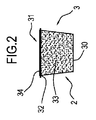
図2は、図1の機械によって生産することができる抽出または注入飲料用の使い捨てカプセルの概略図である。 FIG. 2 is a schematic view of a disposable capsule for extracted or infused beverages that can be produced by the machine of FIG.
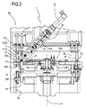
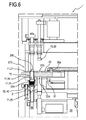
図3は、図1の機械の放出ユニットの側面図である。 FIG. 3 is a side view of the discharge unit of the machine of FIG.
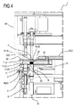
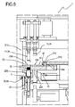
図4から図6は、異なる動作工程に応じて図3の放出ユニットの対応する側面図を部分的に断面で示す。 4 to 6 partially show in cross-section a corresponding side view of the discharge unit of FIG. 3 according to different operating steps.
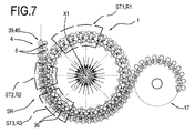
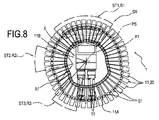
図7および図8は、図1の機械の放出ユニットの細部の平面図である。 7 and 8 are plan views of details of the discharge unit of the machine of FIG.
図9は、図1の機械の放出ユニットのさらなる実施形態の概略図である。 FIG. 9 is a schematic view of a further embodiment of the discharge unit of the machine of FIG.
添付の図面を参照して、符号1は、抽出または注入飲料用の使い捨てカプセル3またはポッドを形成する容器2に注入または抽出製品を放出するユニットを示している。
With reference to the accompanying drawings,
製品は好ましくは、コーヒー、茶、カモミール、牛乳、チョコレートもしくはこれらの組み合わせ等の粉末状、果粒状または葉状の固形製品である。 The product is preferably a powdered, fruity or leafy solid product such as coffee, tea, chamomile, milk, chocolate or combinations thereof.
放出ユニット1は、使い捨てカプセル3を形成する容器2に粉末状の製品好ましくはコーヒーを充填するのに特に好適である。
The
より具体的には、図2に示す通り、抽出または注入飲料用の使い捨てカプセル3は、限定するものではないが最小限の態様では、(通常、接頭円錐形を形成している)硬質カップ状容器2と、硬質容器2に収容される一回の分量33の抽出または注入製品と、硬質容器2の上部開口部31を閉じるための蓋34とを備える。硬質カップ状容器2は、基部30と、カラー32を有する上部開口部31と、を備える。
More specifically, as shown in FIG. 2, the
なお、このタイプのカプセル3は、一つ以上のフィルタ要素または製品保持要素(簡単化のため図示せず)を有することができることを記載しておく。
It should be noted that this type of
図2に示すカプセル3においては、硬質カップ状体2が、一回の分量33の製品が充填される容器を構成している。
In the
本発明にかかる放出ユニット1を用いて、他のタイプのカプセル、例えば、一回の分量33の製品が硬質体に連結されたフィルタ要素内に収容されるとともに保持されているカプセルや、硬質体が底部で閉じられており、また開けることができるカプセルに、充填することもできる。
Using the
言い換えれば、図示しないカプセルにおいては、フィルタ要素が、一回の分量33の製品を収容するとともに保持しており、フィルタ要素が連結される硬質体と組み合わされて、容器を構成することができる。
In other words, in a capsule (not shown), the filter element accommodates and holds a
なおまた、図示しない他の実施形態では、放出ユニット1は、使い捨てポッドの一部分を構成する一以上のストリップ状のフィルタ材(好ましくは紙ベースの)に製品を放出できることを記載しておく。
It should be noted that in other embodiments not shown, the
したがって、一以上のストリップ状のフィルタ材は、上述の容器2を構成する。
Therefore, one or more strip-shaped filter materials constitute the
以下の説明において、硬質カップ状体2を容器として記載するが、本発明を、
容器要素が、フィルタ要素(または一回の分量33の製品を収容するよう設計されたカプセルの他の部材)によって、およびフィルタ要素が接続されるそれぞれの硬質体によって形成されるカプセル、
または、一回の分量の製品を収容する一片以上のフィルタ材から構成されるポッドにも適用できることは理解されよう。
In the following description, the hard cup-
Capsules in which the container element is formed by a filter element (or other member of a capsule designed to accommodate a single dose of 33 products) and by the respective rigid body to which the filter element is connected,
Alternatively, it will be understood that the present invention can also be applied to a pod composed of one or more pieces of filter material containing a single quantity of product.
本発明にかかる使い捨てカプセル3を形成する容器2に抽出または注入飲料用の製品を放出するユニット1は、
一回の分量33の製品を収容するための、側壁を有する少なくとも一つの収容受け部S1と、
一回の分量33の製品を定義するよう、収容受け部S1に製品を供給するための装置6と、
一回の分量33を圧縮するよう、受け部S1に収容された一回の分量33に作用する、一回の分量33の製品を圧縮(コンパクト化)するための装置70と、
容器2を移送するためのライン4と、
閉経路PSに沿って少なくとも一つの第一受け部S1を移動させるための装置10と、
収容受け部S1の外部へと抜け出るのを制御するよう、収容受け部S1に収容された一回の分量33に作用する、収容受け部S1から一回の分量を排出するための装置71と、
圧縮装置70および排出装置71を制御し動作させるためのユニット15と、
を備える。
A
At least one receiving portion S1 having a side wall for receiving a single amount of
A
A device 70 for compressing (compacting) the product of the
A
A device 10 for moving at least one first receiving part S1 along a closed path PS;
A device 71 for discharging a single dose from the storage receptacle S1, acting on the
A
Is provided.
以下により詳細に説明する通り、一回の分量33の製品を圧縮して一回の分量33を密着させて、放出ユニット1の動作条件において、一回の分量33を収容受け部S1の側壁と安定して連結させるような力で圧縮装置70を作動させるように、制御・動作ユニット15が構成されている。
As will be described in more detail below, the
この連結により、放出ユニット1の動作条件において、一回の分量を押し出すための機械的作用がない状態では、すなわち一回の分量に作用する機械的押し出し要素が移動しない場合、製品が収容受け部S1から抜け出るのが防止される。
Due to this connection, in the operating condition of the
言い換えれば、一回の分量33と接触して収容受け部S1の外側へと直接押し出す機械的要素が不在の場合、一回の分量33と収容受け部S1との間の連結、および一回の分量33の製品に与えられた密着力は、放出ユニット1の動作条件において、一回の分量33の製品が(全体的にまたは部分的に)収容受け部S1からこぼれないようにされた連結、および密着力である。
In other words, if there is no mechanical element that contacts the
なお、語句「動作条件」は、放出ユニット1が使用時において動作する、例えば製品の条件(湿度、粘稠度、温度、粒径、弾性率など)並びに収容受け部S1の移動速度および軌道等の一セットの条件を意味することを記載しておく。
The phrase “operating condition” means that the
好ましくは、制御・動作ユニット15は約50,000〜約200,000Pa(つまり、約0.5気圧〜約2気圧)の圧力を生成する圧縮力を一回の分量33の製品に印加するよう圧縮装置70を動作させるよう構成される。
Preferably, the control and
一の面では、制御・動作ユニット15は、放出ユニット1の動作条件を示している、少なくとも一つの収容受け部S1の移動速度を表す信号を受信するよう構成されている。
In one aspect, the control /
この面では、制御・動作ユニット15は、少なくとも、少なくとも一つの収容受け部S1の移動速度を表す信号に応じて圧縮力を調整するよう、圧縮装置70を制御するように構成される。
In this aspect, the control /
この面では、収容受け部S1の内側の一回の分量の圧縮力は、一定である、または収容受け部S1の移動速度の増加とともに増加する。 In this aspect, the amount of compressive force in a single portion inside the receiving portion S1 is constant or increases with an increase in the moving speed of the receiving portion S1.
より具体的には、好ましくは、収容受け部S1の移動速度の所定の値から始まり、所定速度差を超過するまで、圧縮力は一定である。所定速度差を超えると、圧縮力は増加する。 More specifically, preferably, the compression force is constant, starting from a predetermined value of the moving speed of the housing receiving part S1, until a predetermined speed difference is exceeded. When the predetermined speed difference is exceeded, the compression force increases.
この面では、好ましくは、速度に応じた圧縮力は、「段差状に(ステッピング式に)」変更される。 In this aspect, preferably, the compressive force according to the speed is changed “in a step shape (stepping type)”.
直前に説明した面と組み合わせることができる、またはできない、さらに他の面では、制御・動作ユニット15は、放出ユニット1の上述の動作条件を示す製品の物理的/化学的特性(例えば湿度、粘稠度、温度、粒径、弾性率)を表す一つ以上の信号を受信するよう構成される。
In yet another aspect, which may or may not be combined with the previously described aspects, the control and
この面では、制御・動作ユニット15は、少なくとも、製品の化学的/物理的特性を表す一つ以上の信号に応じて収容受け部S1における一回の分量の圧縮力を調整するよう、圧縮装置70を制御するように構成される。
In this aspect, the control /
好適には、この面では、制御・動作ユニット15は、一回の分量33を形成する製品の湿度および/または粒径および/または温度および/または弾性率および/または粘稠度を表す一つ以上の信号に応じて収容受け部S1における一回の分量の圧縮力を調整するよう、圧縮装置70を制御する。
Preferably, in this aspect, the control and
例えば、湿った製品を、より湿っていない製品の圧縮力未満の圧縮力で圧縮することができる。 For example, a wet product can be compressed with a compression force that is less than the compression force of a less wet product.
収容受け部S1の移動に関して、以下に詳細を記載する。 Details regarding the movement of the housing receiving portion S1 will be described below.
好ましくは、第一実施形態においては、収容受け部S1の移動に関する閉経路PSは水平面内にある。 Preferably, in the first embodiment, the closed path PS related to the movement of the accommodation receiver S1 is in a horizontal plane.
あるいは、図9に示す第二実施形態においては、閉じた移動経路PSは鉛直面内にある。 Alternatively, in the second embodiment shown in FIG. 9, the closed movement path PS is in the vertical plane.
なお、好ましくは、移動装置10は、少なくとも一つの収容受け部S1を移動させるよう設計され、第一回転軸X1回りに閉経路PSに沿った回転において少なくとも一つの収容受け部S1を支持する第一回転軸X1回りに回転する第一要素9を備えることを記載しておく。 Preferably, the moving device 10 is designed to move at least one receiving receptacle S1, and supports the at least one receiving receptacle S1 in rotation around the first rotation axis X1 along the closed path PS. It is described that the first element 9 that rotates around one rotation axis X1 is provided.
好ましくは、一の実施形態においては、閉経路PSは円形状の経路である。 Preferably, in one embodiment, the closed path PS is a circular path.
さらにより一般的に言うと、好ましくは、閉経路PSを曲線状の経路である。 Even more generally speaking, the closed path PS is preferably a curved path.
好ましくは、収容受け部S1は、移動の所定方向に応じて閉経路PSに沿って移動する。 Preferably, the accommodation receiver S1 moves along the closed path PS in accordance with a predetermined direction of movement.
なお、必ずしも必須ではないが、好ましくは、閉経路PSに沿った収容受け部S1の移動方向は、閉経路PSに沿って受け部S1が完全に一周する移動の間に決して反転しないことを記載しておく。 Although not necessarily essential, it is preferable that the moving direction of the receiving portion S1 along the closed path PS is never reversed during the movement of the receiving portion S1 completely along the closed path PS. Keep it.
言い換えれば、それぞれの受け部S1に関して、閉経路PSに沿って運動が反転することはない。 In other words, the motion does not reverse along the closed path PS with respect to the respective receiving portions S1.
なお、回転軸X1は、図示する実施形態においては、鉛直方向であることを記載しておく。 It should be noted that the rotation axis X1 is a vertical direction in the illustrated embodiment.
あるいは、図9に示す実施形態において、回転軸X1は水平方向である。 Alternatively, in the embodiment shown in FIG. 9, the rotation axis X1 is in the horizontal direction.
好ましくは、放出ユニット1は、回転時に第一回転要素9によって担持されるよう第一回転要素9に放射状に配置される複数の収容受け部S1を備える。
Preferably, the
なお、好ましくは、収容受け部S1は、回転要素9の円の円弧に沿って配置され、さらにより好ましくは、第一軸X1の点を中心とする全周に沿って配置されることを記載しておく。 In addition, Preferably, accommodation receiving part S1 is arrange | positioned along the circular arc of the circle of the rotation element 9, More preferably, it arrange | positions along the perimeter centering on the point of the 1st axis | shaft X1. Keep it.
さらに好ましくは、第一収容受け部S1は、互いから等角状に第一軸X1の点を中心とする円周に沿って配置されている。 More preferably, the first receiving portions S1 are arranged equiangularly from each other along a circumference centered on the point of the first axis X1.
なおまた、それぞれの収容受け部S1は、供給装置6から製品を受ける領域、および製品が−排出装置71の押し出し作用によって−収容受け部S1から放出される領域に、周期的に移動することを記載しておく。
In addition, each of the receiving portions S1 periodically moves to a region that receives a product from the
なお、再び収容受け部S1(以下「第一受け部」ともいう)に関して、好ましくは、第一受け部は、側壁を有するキャビティ18と可動底壁Fとによって定義されることを記載しておく。
It should be noted that, with respect to the accommodation receiving portion S1 (hereinafter also referred to as “first receiving portion”), preferably, the first receiving portion is defined by the
この面では、好ましくは、放出ユニット1の圧縮装置70は、それぞれの収容受け部S1毎に、
下部位置と上部位置との間で移動可能であり、収容受け部S1の上述の可動底壁Fを形成する第一ピストン13と、
収容受け部S1の内側の容積を調整するよう、下部位置と上部位置との間で第一ピストン13を移動させるための第一ピストン13の移動手段14と、
を備える。
In this aspect, preferably, the compression device 70 of the
A
Moving means 14 of the
Is provided.
なお、第一ピストン13はそれぞれ回転要素9によって回転されることを記載しておく。
It should be noted that each
より具体的には、第一ピストン13は、回転要素9の軸X1に対して所定の径方向位置に配置される。
More specifically, the
好適には、放出ユニット1は、それぞれの収容受け部S1毎に、非動作位置と、第一ピストン13と協働して一回の分量33を圧縮するよう収容受け部S1の内側の一回の分量33を圧縮する動作位置と、の間で移動可能な圧縮要素26を備える。
Preferably, the
好ましくは、一回の分量33の圧縮は、圧縮方向に沿って行われ、これにより、収容受け部S1の側壁に向かって一回の分量33を径方向に押し潰す。
Preferably, the one-
好ましくは、圧縮要素26は、非動作位置と動作位置との間で鉛直方向に移動可能である。圧縮要素26は、充填ステーションSRの回転要素9に接続される(担持される)。好ましくは、ユニット1は、それぞれの収容受け部S1毎に、圧縮要素26を備える。
Preferably, the
図示しない他の実施形態において、圧縮要素26を省略し、固定接触要素例えばプレートで置き換えることもできる。一回の分量33の製品は、第一ピストン13の圧縮作用によって固定接触要素に向かって押圧される。
In other embodiments not shown, the
他の面では、排出装置71は、少なくとも一つの収容受け部S1の内側の一回の分量33と接触し、収容受け部S1の外側へと一回の分量を排出して放出する少なくとも一つの移動可能な排出要素36を備える。
In another aspect, the discharge device 71 contacts at least one
なお、こうして、収容受け部S1からの一回の分量の排出が、移動可能な排出要素36の押し出し作用(能動的な作用)によって行われることを記載しておく。
It should be noted that in this way, one discharge of the amount from the receiving receptacle S1 is performed by the pushing action (active action) of the
移動可能な排出要素36の押圧がない場合、圧縮装置70によって一回の分量33へと先に印加された圧力により、一回の分量は、したがって、収容受け部S1に着実にかつ安定して連結され、放出ユニット1の動作条件において、一回の分量33は(全体的にまたは部分的に)収容受け部S1から抜け出ることがなくなることになる。
In the absence of a pressing of the
好適には、制御・動作ユニット15は、一回の分量33に押し込む力を印加して、収容受け部S1の外側へと放出できるよう、移動可能な排出要素36を制御するように構成される。
Preferably, the control and
好適には、制御・動作ユニット15は、一回の分量33を収容受け部S1の外側へと押し出すよう、移動可能な排出要素36を制御するように構成される。
Preferably, the control and
本発明の一の面の好ましい実施形態では、制御・動作ユニット15は、一回の分量33の重力による落下の速度未満である排出速度で、一回の分量33を収容受け部S1の外側へと押し出すよう、移動可能な排出要素36を制御する。排出速度が低減されることにより、特に重力によって落下する速度未満に低減されることにより、容器2から離れ出る空気の乱流を最小限にすることができ、したがって、容器2から製品がこぼれるのを最小限にすることができる。
In a preferred embodiment of one aspect of the invention, the control and
好ましくは、ユニット1は、それぞれが収容受け部S1に機能的に作用するべく対応する収容受け部S1に関連している複数の排出要素36を備える。
Preferably, the
放出ユニット1の使用を簡潔に説明する。この使用に関する説明から、本発明の利点を見出すことができよう。
The use of the
供給装置6は、所定の放出領域において、収容受け部S1に所定量の製品を放出するよう構成される。
The
なお、製品が収容受け部S1へと放出された後、圧縮要素26が作動することを記載しておく。
It should be noted that the
圧縮要素26は、図3〜図8に示す実施形態において、収容受け部S1へと入り込んでいる一回の分量33の製品と接触して、一回の分量33を圧縮する。
In the embodiment shown in FIGS. 3 to 8, the
なお、収容受け部S1における製品は、底部Fによって支持され、収容受け部S1の側壁の内側に収容されることを記載しておく。 It should be noted that the product in the receiving portion S1 is supported by the bottom portion F and is stored inside the side wall of the receiving portion S1.
このため、圧縮要素26の作用は、製品が−底部および側壁の存在により収容受け部S1に閉じ込められて拘束されている−、径方向に拡大し、側壁と接触して側壁との連結が形成されることを意味する。
For this reason, the action of the
さらに、圧縮作用に従って、一回の分量33を形成する製品が密着する。
Furthermore, according to the compression action, the products forming a
圧縮の状態においては、すなわち、一回の分量が圧縮されたときには、押し出し作用が一回の分量に印加されない限り、収容受け部S1の底部Fがない状態であっても、一回の分量が(全体的にまたは部分的に)収容受け部S1から抜け出ない。 In the compressed state, that is, when a single dose is compressed, the single dose is reduced even if the bottom portion F of the receiving portion S1 is not present unless the pushing action is applied to the single dose. It does not come out of the receiving part S1 (in whole or in part).
このため、製品が意図せずこぼれることなく、収容受け部S1の底部Fを取り出すことができる(例えば、ピストン13がもはや上述の底壁Fを構成しないよう、ピストン13を移動させることができる)。
For this reason, the bottom F of the receiving portion S1 can be taken out without unintentionally spilling the product (for example, the
一回の分量33に印加される圧縮は、好適には、放出ユニット1の動作条件、すなわち収容受け部S1の速度および軌道、つまり処理される製品の化学的/物理的特性に依存する。一回の分量33を押し出す機械的作用がない場合、すなわち、一回の分量33と接触し収容受け部S1の外側へと押し出す機械的要素が不在の場合には、一回の分量33に印加される圧縮により、放出ユニット1の動作条件において、収容受け部S1から一回の分量33全体がまたは一回の分量33の一部が抜け出るのを防止する。
The compression applied to the
この面では、収容受け部S1からの一回の分量33の製品の排出が排出装置71を用いて実行される放出位置まで閉経路PSに沿って製品が抜け出ることなく、収容受け部S1を移動させることができる。
In this aspect, the product receiving portion S1 is moved along the closed path PS to the discharge position where the discharge of the product of the
この放出位置において、収容受け部S1から製品を排出することを目的とした押し出し作用を印加するよう、排出装置71は収容受け部S1において動作する。 In this discharge position, the discharge device 71 operates in the storage receiving portion S1 so as to apply a pushing action intended to discharge the product from the storage receiving portion S1.
なお、添付の図面に示す実施形態では、放出位置においては、収容受け部S1は底部Fがなく、排出装置71の作用によって、先に可動底部Fによって閉じられていた収容受け部S1の開口部を通じて一回の分量33を排出することが可能になることを記載しておく。
In the embodiment shown in the accompanying drawings, in the discharge position, the receiving portion S1 does not have the bottom portion F, and the opening portion of the receiving portion S1 previously closed by the movable bottom portion F by the action of the discharge device 71. Note that it is possible to discharge a
あるいは、図9に示す実施形態において(以下により詳細に説明する)、放出位置において、底部Fは、可動底部Fと反対側の開口部を通じて一回の分量を排出するよう一回の分量を圧縮して排出する機能を有する。 Alternatively, in the embodiment shown in FIG. 9 (discussed in more detail below), at the discharge position, the bottom F compresses a single dose to discharge a single dose through the opening opposite the movable bottom F. And has a function of discharging.
このため、本実施形態において、収容受け部S1の可動底部Fは圧縮装置70および排出装置71を構成する。 For this reason, in this embodiment, the movable bottom part F of the accommodation receiving part S1 constitutes the compression apparatus 70 and the discharge apparatus 71.
なお、本発明は、好適には、所定の値までの一回の分量の圧縮により、異なる処理ステーション間の収容受け部S1の移動の間に製品が抜け出るのを防止し、一回の分量33に対する押し出し作用によってのみ、一回の分量を収容受け部S1から追い出すことを可能にすることを記載しておく。
Note that the present invention preferably prevents the product from slipping out during the movement of the receiving portion S1 between different processing stations by compressing a single amount up to a predetermined value, and a
実際には、一回の分量の圧縮は、一回の分量が(製品と受け部の側壁との間の摩擦作用により)収容受け部S1の側壁に付着され、収容受け部S1において密着し、かつコンパクト化されたブロック状の製品になることを意味する。 In practice, a single compression is applied to the side wall of the receiving part S1 (due to the friction between the product and the side wall of the receiving part) and is in close contact with the receiving part S1, And it means to become a compact block-like product.
ユニット1は、好適には、使用時において、機械の可動部品が早く摩耗し信頼性が低下する原因となり、かつ、硬質体2が汚れる原因となる、放出ユニット1における製品の飛び散りを防止する。
The
なお、本発明にかかる放出ユニット1は、構造の点から特に簡単であり、同時に非常に融通性が高く、種々のタイプの製品および/または種々の大きさのカプセルもしくはポッドの部材に容易に適合可能であることを記載しておく。
The
また、本発明において定義される、抽出または注入飲料用の使い捨てカプセル3を包装するように設計される包装機械100は、上述した放出ユニット1と、容器2を移送するためのライン4と、使い捨てカプセル3の容器要素2を移送ライン4の対応する支持収容部5に送出するためのステーションSAと、容器2をそれぞれの一片の密封シート34で閉じるためのステーションSCと、移送ライン4の支持収容部5からカプセル3を取り出す取り出しステーションSUと、を備える。
Also, a
添付の図面に示す包装機械100のいくつかの部分を説明する。
Several parts of the
なお、機械100は、容器をすなわち硬質カップ状体2を移送する(すなわち、移動させる)のためのライン4を備えることを記載しておく。
It should be noted that the
移送ライン4は、第一移動経路Pに沿って延設されるとともに、第一経路Pに沿って連なって配置される硬質容器2を支持するための複数の受け部5を有する。
The
好ましくは、第一移動経路Pは水平面内にある閉経路である。 Preferably, the first movement path P is a closed path in a horizontal plane.
支持受け部5は一つずつ次々と配置されているが、必ずしも連続的に配置されている必要はない。
The
さらに、支持受け部5はそれぞれ、対応する延設の垂直軸を有する。
Further, each of the
なお、移送ライン4は、第一経路Pに沿って移動するよう支持収容部5が接続される移送要素39を備えることを記載しておく。
It should be noted that the
なお、移送要素39は、垂直軸回りに回転して移送要素39を移動させる移動手段17の周囲にループ状に閉じていることを記載しておく。 It should be noted that the transfer element 39 is closed in a loop around the moving means 17 that moves around the vertical axis to move the transfer element 39.
好ましくは、移送要素39は、チェーン40である。チェーン40は、対応する垂直軸回りに連続的に互いにヒンジ状に連結されて無限ループを形成する複数のリンクを備える。
Preferably, the transfer element 39 is a
なお、リンクのうちの少なくとも一つは、少なくとも一つの支持受け部5を備えており、少なくとも一つの支持受け部5は、開口部31が上方を向いた状態で配置され得る対応する硬質容器2に対する垂直軸を有することを記載しておく。
At least one of the links is provided with at least one
必ずしもそうである必要はないが、好ましくは、移送要素39が連続的に移動することができるよう、移動手段17は、垂直軸回りに連続的に回転する。 Although not necessarily so, preferably the moving means 17 is continuously rotated about a vertical axis so that the transfer element 39 can move continuously.
図示する実施形態において、ユニット1は、一回の分量33を受けるための位置P1と一回の分量33をそれぞれの容器(硬質体2)の内側に放出するための位置P2との間で閉経路PSに沿って、収容受け部S1の位置を調整するよう構成された、収容受け部S1の位置を調整するための装置11を備える。
In the illustrated embodiment, the
さらに、ユニット1は、上述の供給装置6が内部に配置される、少なくとも一つの収容受け部S1の内側に一回の分量33の形成するためのサブステーションST1を備える。
Further, the
放出ユニット1は、また、一回の分量を放出するための位置P2に配置される少なくとも一つの収容受け部S1から(移送ライン4によって移送された)容器2へと一回の分量の製品を放出するためのサブステーションST3を備える。
The
なお、圧縮装置70は、形成サブステーションST1と放出サブステーションST3との間の収容受け部S1の経路において動作することを記載しておく。 It should be noted that the compression device 70 operates in the path of the receiving portion S1 between the forming substation ST1 and the discharge substation ST3.
なお、排出装置71は放出サブステーションST3において動作することを記載しておく。 It should be noted that the discharge device 71 operates in the discharge substation ST3.
位置を調整するための装置11は、少なくとも一つの収容受け部S1を、一回の分量を形成するためのサブステーションST1においては一回の分量を受けるための位置P1に配置し、一回の分量を放出するためのサブステーションST3においては一回の分量を放出するための位置P2に配置するよう、構成されている。 The apparatus 11 for adjusting the position arranges at least one receiving receptacle S1 at a position P1 for receiving a single dose in the substation ST1 for forming a single dose. The substation ST3 for discharging a quantity is configured to be arranged at a position P2 for discharging a quantity once.
ユニット1および/または機械100の部品を構成するすべての上述の部材を、添付図面を特に参照してより詳細に説明する。
All the above-mentioned components constituting the
なお、それぞれの収容受け部S1は、一回の分量を形成するためのサブステーションST1と一回の分量を放出するためのサブステーションST3と周期的に−回転の間に−係合するよう、回転時には第一回転要素9によって移動することを記載しておく。 In addition, each accommodation receiving part S1 is engaged with the substation ST1 for forming a single dose and the substation ST3 for discharging a single dose periodically, during the rotation. It is described that the first rotating element 9 moves during rotation.
なお、位置を調整するための装置11は、収容受け部S1を、形成サブステーションST1においては受けるための位置P1に配置し、一回の分量を放出するためのサブステーションST3においては放出するための位置P2に配置することができることを記載しておく。 In addition, the apparatus 11 for adjusting the position arranges the receiving portion S1 at the position P1 for receiving in the forming substation ST1, and discharges it in the substation ST3 for discharging a single dose. It is described that it can be arranged at the position P2.
添付の図面に示す実施形態においては、収容受け部S1は径方向に移動可能に第一回転要素9によって支持されている。 In the embodiment shown in the accompanying drawings, the receiving portion S1 is supported by the first rotating element 9 so as to be movable in the radial direction.
この面に関して、調整装置11は、少なくとも一つの収容受け部S1を、第一回転軸X1に対して径方向に、一回の分量を受けるための位置P1と一回の分量を放出するための位置P2との間で移動させるよう構成されている。 With respect to this surface, the adjusting device 11 releases at least one accommodation receiving part S1 in the radial direction with respect to the first rotation axis X1 at a position P1 for receiving a single dose and a single dose. It is configured to move between the position P2.
より具体的には、調整装置11は、少なくとも一つの収容受け部S1を、送り方向(フォーワード)ストロークにおいては一回の分量を受けるための位置P1から一回の分量を放出するための位置P2へと、戻り方向(リターン)ストロークに応じては一回の分量を放出するための位置P2から一回の分量を受けるための位置P1へと、径方向に移動させるよう構成されている。 More specifically, the adjusting device 11 discharges at least one accommodation receiving portion S1 from a position P1 for receiving a single dose in a feed direction (forward) stroke. In accordance with the return direction (return) stroke, P2 is configured to move in a radial direction from a position P2 for discharging a single dose to a position P1 for receiving a single dose.
図示する実施形態においては、収容受け部S1は、一回の分量を収容するための要素20(好ましくは長手形状である)において形成される。 In the illustrated embodiment, the receiving receptacle S1 is formed in an element 20 (preferably in the shape of a longitudinal shape) for receiving a single dose.
好ましくは、収容受け部S1は、一回の分量を収容するための要素20に形成された貫通受け部である。 Preferably, the receiving portion S1 is a penetration receiving portion formed in the element 20 for receiving a single dose.
言い換えれば、収容受け部S1は、収容要素20の上面と下面との間で貫通するよう延設されている。 In other words, the accommodation receiving portion S1 extends so as to penetrate between the upper surface and the lower surface of the accommodation element 20.
好ましくは、収容受け部S1は円筒形状を有する、すなわち、断面が円形である。 Preferably, the receiving portion S1 has a cylindrical shape, that is, a circular cross section.
他の面では、放出ユニット1は、上部開口部23A,23Bおよび下部開口部22A,22Bが形成されている、収容要素20を収容するための(ハウジングのための)要素21を備える。
In another aspect, the
好ましくは、ハウジング要素21は、位置が変わらない状態で回転要素によって回転されるよう、回転要素9に固定される。 Preferably, the housing element 21 is fixed to the rotating element 9 so that it can be rotated by the rotating element without changing its position.
実際には、ハウジング要素21はハウジングキャビティを定義する。ハウジングキャビティの内側には、収容要素20が、一回の分量を受けるための上述の位置P1と一回の分量を放出するための位置P2との間で移動可能となるよう、移動可能に挿入される。 In practice, the housing element 21 defines a housing cavity. Inside the housing cavity, the receiving element 20 is movably inserted so as to be movable between the aforementioned position P1 for receiving a single dose and a position P2 for releasing a single dose. Is done.
容器要素21およびハウジング要素20は回転要素9によって支持され、よって、また、回転要素9の回転により、これらの要素20,21の回転が設定される。 The container element 21 and the housing element 20 are supported by the rotating element 9, so that the rotation of these elements 20, 21 is set by the rotation of the rotating element 9.
放出ユニット1はまた、互いに対向する側壁11A,11Bを有する軌道すなわちカム57を備える。好ましくは、軌道57は閉ループ経路に延設されている。
The
一回の分量を収容するための要素20は、一回の分量を収容するための要素20の位置を閉経路PSに沿って調整可能に、軌道57と係合するよう構成される。
The element 20 for receiving a single dose is configured to engage the
なお、軌道57は放出ユニット1のフレーム29に対して固定される、つまり、回転要素9とは一体的に回転しないことを記載しておく。
It should be noted that the
なお、実際には、一回の分量を収容するための要素20は、軌道57に挿入されるように設計された部分すなわちカム従動子20aを有することを記載しておく。
It should be noted that in practice, the element 20 for accommodating a single dose has a portion designed to be inserted into the
なお、部分20aと軌道57とが組み合わさって、閉経路PSに沿って収容受け部S1の位置を調整するよう構成されるカム装置を構成することを記載しておく。
It is described that the cam device configured to adjust the position of the receiving portion S1 along the closed path PS is configured by combining the
なおまた、収容要素20、ハウジング要素21およびカム装置20a,57により、閉経路PSに沿って収容受け部S1の位置を調整するための上記装置11が構成されることを記載しておく。
In addition, it is described that the device 11 for adjusting the position of the receiving portion S1 along the closed path PS is configured by the receiving element 20, the housing element 21, and the
なおまた、ハウジング要素21は、第一上部開口部23Aおよび第二上部開口部23Bが形成されている上部壁50を備えることを記載しておく。
It should be noted that the housing element 21 includes an
第一上部開口部23Aは軸X1に近い位置に配置されており、第二上部開口部23Bは軸X1から離れた位置に配置されている。
The first
またハウジング要素21は、第一下部開口部22Aおよび第二下部開口部22Bが形成されている下部壁51を備える。
The housing element 21 also includes a
第一下部開口部22Aは軸X1に近い位置に配置されており、第二下部開口部22Bは軸X1から離れた位置に配置されている。
The first
好ましくは、第一上部開口部23Aは第一下部開口部22Aと鉛直方向において重なり合っている。好ましくは、第二上部開口部23Bは第二下部開口部22Bと鉛直方向において重なり合っている。
Preferably, the first
第一および第二開口部22A,22B,23A,23Bは、ハウジング要素21によって定義されるとともに、内側に収容要素20が径方向に移動できるハウジングキャビティと連通状態にある。
The first and
収容要素20、したがって収容受け部S1は、
第一上部開口部23Aおよび第一下部開口部22Aが鉛直方向に並んでいる状態である、一回の分量33を受けるための第一位置P1と、
第二上部開口部23Bおよび第二下部開口部22Bが鉛直方向に並んでいる状態である、一回の分量33を受けるための第二位置P2と、
に配置されるよう移動可能である。
The storage element 20, and thus the storage receiver S1,
A first position P1 for receiving a
A second position P2 for receiving a
It is movable so that it may be arranged.
つまり、収容受け部S1が第1上部開口部23Aおよび下部開口部22Aと鉛直方向に並んで配置される場合、収容受け部S1は一回の分量を受けるための位置P1にあり、一方、収容受け部S1が第二上部開口部23Bおよび下部開口部22Bと鉛直方向に並んで配置される場合、収容受け部S1は一回の分量33を放出するための位置P2にある。
That is, when the accommodation receiving part S1 is arranged in the vertical direction with the first
なお、放出ユニット1はさらに、収容受け部S1の内側の一回の分量を圧縮するように構成される、一回の分量を圧縮するためのサブステーションST2を備えることを記載しておく。
In addition, it describes that the discharge | release
圧縮装置70は圧縮サブステーションST2において動作する。 The compression device 70 operates in the compression substation ST2.
圧縮サブステーションST2は、一回の分量を形成するためのサブステーションST1と一回の分量を放出するためのサブステーションST3との間で閉経路PSに沿って配置される。 The compression substation ST2 is arranged along the closed path PS between the substation ST1 for forming a single dose and the substation ST3 for discharging a single dose.
以下に、一回の分量を形成するサブステーションST1を説明する。 Below, substation ST1 which forms the amount of one time is demonstrated.
一回の分量を形成するためのサブステーションST1は、一回の分量を形成するための領域R1に配置される。 The substation ST1 for forming a single dose is arranged in a region R1 for forming a single dose.
一回の分量を形成するためのサブステーションST1には、一回の分量33を形成するための領域R1に配置された収容受け部S1の内側に(一回の分量33を構成する)所定量の製品を放出するよう設計された供給装置6が備えられる。
The substation ST1 for forming a single dose has a predetermined amount (constituting the single dose 33) inside the receiving portion S1 disposed in the region R1 for forming the
第一実施形態にかかる供給装置6は、底部に製品の出口を有する(使用時には製品が充填されている)ホッパ38を備える。
The
好ましくは、ホッパ38は、一つ以上の収容受け部S1の内側に製品を供給するために回転するよう設計された一つ以上のスクリューフィーダ41aを収容することができる。
Preferably, the hopper 38 can accommodate one or
一回の分量を形成するための領域R1における上述の第一ピストン13の移動に関して、以下に説明する。
The movement of the
好ましくは、上述の収容受け部S1が一回の分量を形成するための領域R1の内側にある場合、特に送入(インフィード)区域においては、収容受け部S1に関連する第一ピストン13は、収容受け部S1に所定空間を形成する所定の(鉛直)位置に配置される。
Preferably, when the above-described receiving portion S1 is inside the region R1 for forming a single dose, the
本発明により、一回の分量を形成するための領域R1において移動手段14を用いて第一ピストン13の位置を(鉛直方向に)変更することによって、収容受け部S1に収容される製品の量を変更することができる、あるいは言い換えれば、一回の分量33を変更することができる。基本的に、移動手段14は、一回の分量33を形成するための領域R1の送出区域において、一回の分量33を定義するよう、所望の供給位置に第一ピストン13を位置決めするよう設計されている。
According to the present invention, by changing the position of the first piston 13 (in the vertical direction) using the moving means 14 in the region R1 for forming a single dose, the amount of the product accommodated in the accommodation receiver S1. Can be changed, or in other words, the
圧縮装置70のいくつかの面を、図3〜図8に示す実施形態に関して、より詳細に説明する。 Several aspects of the compression device 70 will be described in more detail with respect to the embodiment shown in FIGS.
なお、圧縮要素26は、一回の分量を圧縮するためのサブステーションST2においては下降動作位置に配置されることを記載しておく。
It should be noted that the
圧縮要素26は、第一ピストン13の上方に配置される。
The
実際には、圧縮要素26は、下降動作位置において、収容要素20の上部壁50の第一上部開口部23Aを通じて挿入可能な位置に、回転要素9に対して配置される。
In practice, the
一方、第一ピストン13が収容要素20の下部壁51の第一下部開口部22Aを通過可能な位置に、第一ピストン13は回転要素9に対して配置される。
On the other hand, the
なお、製品を圧縮/コンパクト化するよう、第一収容部S1の内側に配置される一回の分量33との上部接触要素を、圧縮要素26の下面が圧縮領域R2において構成していることを記載しておく。
In order to compress / compact the product, the lower contact surface of the
言い換えれば、一回の分量33は、第一ピストン13と圧縮要素26との間で、圧縮要素26によって印加される圧縮の作用によって圧縮される。
In other words, the
あるいは、一回の分量33が形成されると、製品を圧縮するよう第一ピストン13を移動させることができ、そして、圧縮要素26を第一ピストン13に対する固定接触要素として機能させることができる。言い換えれば、一回の分量33を、第一ピストン13と圧縮要素26との間で、一方もしくは他方をまたは両方を動作させることによって、圧縮することができる。
Alternatively, once a
好適には、例えば、第一ピストン13および/または圧縮要素26に接続されたバネまたは空気圧式要素などの、過荷重を防止する装置を備えることもできる。
Suitably, a device for preventing overloading can also be provided, for example a spring or a pneumatic element connected to the
排出要素36は、容器2を上昇させるためのピストン23の上方に配置される。
The
なお、ユニット1はまた(図3〜図8に示す実施形態において)、一回の分量を放出するためのサブステーションST3において下部位置と容器2を上昇させる上部位置との間で移動可能である、容器2を上昇させるためのピストン23を備えることを記載しておく。
It should be noted that the
好ましくは、放出ユニット1は、それぞれの収容受け部S1に対して上昇ピストン23を備える。好ましくは、それぞれのピストン23は、回転要素9によって第一受け部S1と一体的に回転される。
Preferably, the
実際には、下降動作位置において、排出要素36が上部壁50の第二上部開口部23Bを通じて挿入可能な位置に、排出要素36はハウジング要素21に対して配置される。
Actually, the
なお、排出装置36の下面は、一回の分量を放出するための領域R3においては、収容受け部S1の内側に配置された一回の分量33と上部で接触し、一回の分量33を収容受け部S1の外部に向かって押圧して、上昇ピストン23によって上昇された容器2の内側に一回の分量を放出することを記載しておく。
Note that the lower surface of the
好適には、容器2が上昇ピストン23によって上昇されると、排出要素36は一回の分量33を押し出し、したがって、容器の外側への製品の飛び散りを最小限にするよう、容器2は収容受け部S1の近傍に配置される。
Preferably, when the
図示しない他の実施形態において、圧縮要素26は排出要素36を構成することができる。
In other embodiments not shown, the
なお、一つまたは複数の圧縮要素26、排出要素36、第一ピストン13および上昇ピストン23に関して、上述の要素/装置26,36およびピストン13,23は、回転要素9によって(鉛直方向に移動可能に)支持される、すなわち、所定の径方向位置に配置されることを記載しておく。
Note that with respect to one or
上述の通り、一つまたは複数の圧縮要素26、一つまたは複数の排出装置36、一つまたは複数の第一ピストン13および一つまたは複数の上昇ピストン23は、鉛直方向に移動可能である。
As described above, the one or
図9は、放出ユニット1が、水平回転軸X1回りに回転するよう設計された回転要素9を備えるさらなる実施形態を示す。
FIG. 9 shows a further embodiment in which the
回転要素9には、可動底部Fを有する複数の収容受け部S1が配置されている。 A plurality of receiving portions S1 having a movable bottom F are arranged on the rotating element 9.
可動底部Fは、排出装置71と、そしてまた圧縮装置70と、を構成する。 The movable bottom F constitutes a discharge device 71 and also a compression device 70.
言い換えれば、本実施形態において、底部Fは、一回の分量に対する圧縮要素26および排出要素36として機能する。
In other words, in the present embodiment, the bottom F functions as a
本実施形態では、好ましくは、機械は、(好ましくは紙で形成された)ウェブ状またはストリップ状のフィルタ材74を搬送するための装置73を備える。 In this embodiment, preferably the machine comprises a device 73 for conveying a web-like or strip-like filter material 74 (preferably formed of paper).
好適には、可動底部Fはさらに、一回の分量33が可動底部Fから分離し易くなるよう、回転軸X1に垂直な軸回りに回転する。
Preferably, the movable bottom F is further rotated about an axis perpendicular to the rotation axis X1 so that the
ウェブ状またはストリップ状のフィルタ材74は、収容受け部S1から放出された一回の分量を受けるよう設計されており、容器2を構成する。
The web-like or strip-like filter material 74 is designed to receive a single dose discharged from the receiving portion S <b> 1 and constitutes the
ウェブ状またはストリップ状のフィルタ材74の一片は、対応するポッドを構成することになる。 A piece of web-like or strip-like filter material 74 constitutes a corresponding pod.
なお、ホッパ38から製品を受けた後に、収容受け部S1は、収容受け部S1の送入(インフィード)の上部(底部Fの反対側)を閉じるように設計されており、(フレームに対して固定された)外側接触部76が形成されている角度範囲へと移動することを記載しておく。
After receiving the product from the hopper 38, the receiving portion S1 is designed so as to close the upper part (the opposite side of the bottom F) of the receiving (infeed) of the receiving portion S1 (with respect to the frame). It is described that the
この角度範囲においては、放出ユニット1の動作条件において、一回の分量33を収容受け部S1の側壁と安定して連結させるよう、約50,000〜約200,000Paの範囲(すなわち約0.5気圧〜約2気圧範囲)の圧力を生成する圧縮力で接触要素76と圧縮要素26の間に配置された一回の分量を圧縮するように、圧縮要素26は径方向に外側へ向かって移動される。
In this angular range, a range of about 50,000 to about 200,000 Pa (i.e., about 0. The
次に、収容受け部S1は、接触要素76が途切れる、製品を放出するための角度範囲に移動する。そこでは、一回の分量33を収容受け部S1の外部へと排出する(そして好ましくはその下にある容器2上に放出する)よう、圧縮要素26は外側に向かって径方向に移動される。
Next, the receiving part S1 moves to an angular range for discharging the product, where the
圧縮要素26が径方向に移動しない状態において、一回の分量を収容受け部S1の側壁と安定して連結させるような力で一回の分量33が圧縮されているので、接触要素76が途切れるとすぐに、一回の分量33の製品はまとまりのない状態で収容受け部S1から抜け出し始めることになり、大きな面積の下層のストリップ74上に載置されることになる。
In a state where the
なお、図9の実施形態において、一回の分量33は一回の分量を収容受け部S1から抜け出させようとする遠心力を受けるので、図3〜図8に示す実施形態と比較して、同じ動作速度、一回の分量33の製品の化学的/物理的特性およびサイズでは、一回の分量33がそれぞれの収容受け部S1から抜け出ないようにするために必要な圧縮圧がより高いことを記載しておく。
In the embodiment of FIG. 9, the
本発明ではまた、使い捨てのカプセル3またはポッドを形成する容器2へと抽出または注入飲料用の製品を放出する方法も定義される。
The present invention also defines a method for releasing a product for extraction or infusion beverage into a
方法は、
一連の容器2を第一移動経路Pに沿って移動させる工程と、
移動速度に応じて閉経路PSに沿って一回の分量33の製品を収容するよう設計されている少なくとも一つの収容受け部S1を移動させる工程と、
放出ユニットの収容受け部S1に一回の分量33の製品を放出する工程と、
製品を圧縮して密着させて、一回の分量33を収容受け部S1の側壁と安定して連結させ、放出ユニットの動作条件において、一回の分量を押し出す機械的作用がない状態で、つまり一回の分量に作用する押し出し要素が移動しない状態で、収容受け部S1から一回の分量が抜け出るのを防止する圧縮力で、それぞれの収容受け部S1における一回の分量33の製品を押圧する工程と、
収容受け部S1から一回の分量が抜け出るのを制御するよう、所定の放出区域において一回の分量に押圧のための機械的作用を与える工程と、
を含む。
The method is
Moving the series of
Moving at least one receiving receptacle S1 designed to receive a single dose of 33 products along the closed path PS according to the moving speed;
A step of discharging a product of a quantity of 33 into the receiving unit S1 of the discharge unit;
The product is compressed and brought into close contact, and the
Applying a mechanical action for pressing the single dose in a predetermined discharge area so as to control the single dose exiting from the receiving receptacle S1;
including.
言い換えれば、方法が、放出ユニット1の動作条件において、一回の分量33と接触し収容受け部S1の外側に直接押し出す機械的要素が不在の場合には、一回の分量33の製品が(全体的にまたは部分的に)収容受け部S1から抜け出ないよう、製品を圧縮して密着させて、一回の分量33を収容受け部S1の側壁と安定して連結させるような圧縮力で、それぞれの収容受け部S1における一回の分量33の製品を押圧する工程を含んでいる。
In other words, in the operating conditions of the
好適には、方法は、低い排出速度、特に重力による一回の分量33の落下速度未満で収容受け部S1から一回の分量が抜け出るよう制御するように、所定の放出区域において一回の分量に押圧のための機械的作用を与える工程を含んでいる。
Preferably, the method provides for a single dose in a given discharge area so as to control a single dose to exit the receiving receptacle S1 at a low discharge rate, in particular below the drop rate of a
好ましい実施形態において、方法はまた、放出ユニットの動作条件に応じて圧縮力を調整する工程を含んでいる。 In a preferred embodiment, the method also includes adjusting the compressive force depending on the operating conditions of the discharge unit.
他の面では、閉経路PSに沿って少なくとも一つの収容受け部S1を移動させる工程は、移動の所定方向に応じて曲線状の経路に沿って収容受け部S1を移動させる工程を含んでいる。 In another aspect, the step of moving at least one receiving receptacle S1 along the closed path PS includes the step of moving the receiving receptacle S1 along a curved path according to a predetermined direction of movement. .
この好ましい実施形態において、方法が、少なくとも一つの収容受け部S1の移動速度に応じて圧縮力を調整する工程を含んでいることには利点がある。 In this preferred embodiment, it is advantageous that the method includes the step of adjusting the compression force according to the moving speed of the at least one receiving receptacle S1.
好適には、方法は、一回の分量33の製品の化学的/物理的特性に応じて圧縮力を変更する工程を含んでいる。
Preferably, the method includes the step of changing the compressive force depending on the chemical / physical properties of a
好適には、方法は、一回の分量33を形成する製品の湿度および/または粒径および/または温度および/または弾性率および/または粘稠度に応じて圧縮力を変更する工程を含んでいる。
Preferably, the method comprises the step of changing the compressive force depending on the humidity and / or particle size and / or temperature and / or elastic modulus and / or consistency of the product forming the
Claims (26)
所定の一回の分量(33)の製品を収容するよう設計されるとともに側壁を有する少なくとも一つの収容受け部(S1)と、
前記所定の一回の分量(33)の製品を定義するよう、前記少なくとも一つの収容受け部(S1)に前記製品を供給するよう設計される供給装置(6)と、
前記少なくとも一つの収容受け部(S1)における前記一回の分量(33)の製品を圧縮するよう設計される圧縮装置(70)と、
閉経路(PS)に沿って前記少なくとも一つの受け部(S1)を移動させるよう設計される移動装置(10)と、
前記少なくとも一つの収容受け部(S1)から前記一回の分量(33)を排出するよう設計される排出装置(71)と、
前記圧縮装置(70)および前記排出装置(71)を制御し動作させるよう設計される制御・動作ユニット(15)と、
を備えており、
前記制御・動作ユニット(15)は、前記一回の分量(33)の製品を密着させて、一回の分量(33)を前記少なくとも一つの収容受け部(S1)の前記側壁と安定して連結させ、前記放出ユニットの動作条件において、前記一回の分量(33)を押し出す機械的作用がない状態では前記少なくとも一つの収容受け部(S1)から前記一回の分量(33)が抜け出るのを防止するよう、前記一回の分量(33)の製品に圧縮力を印加するよう前記圧縮装置(70)を制御するように構成されている放出ユニット。 A unit for discharging a product for extraction or infusion into a disposable capsule (3) or a container (2) forming a pod,
At least one receiving receptacle (S1) designed to receive a predetermined single dose (33) of the product and having a side wall;
A supply device (6) designed to supply said product to said at least one receiving receptacle (S1) so as to define said predetermined batch quantity (33) of product;
A compression device (70) designed to compress the single dose (33) of product in the at least one receiving receptacle (S1);
A moving device (10) designed to move the at least one receptacle (S1) along a closed path (PS);
A discharge device (71) designed to discharge the single dose (33) from the at least one receiving receptacle (S1);
A control and operation unit (15) designed to control and operate the compression device (70) and the discharge device (71);
With
The control / operation unit (15) makes the one-time amount (33) of the product in close contact with each other so that the one-time amount (33) is stably attached to the side wall of the at least one receiving portion (S1). In the operating condition of the discharge unit, the one-time quantity (33) comes out of the at least one receiving receptacle (S1) in a state where there is no mechanical action for pushing out the one-time quantity (33). A discharge unit configured to control the compression device (70) to apply a compressive force to the single dose (33) of the product so as to prevent damaging.
前記制御・動作ユニット(15)は、前記放出ユニットの前記動作条件を示している前記少なくとも一つの第一収容受け部(S1)の移動速度を表す信号を受信するよう構成されており、
前記制御・動作ユニット(15)は、少なくとも、前記少なくとも一つの第一収容受け部(S1)の前記移動速度を表す前記信号に応じて、前記少なくとも一つの第一収容受け部(S1)の内側の前記一回の分量(33)への前記圧縮力を調整するよう、前記圧縮装置(70)を制御するように構成される放出ユニット。 The discharge unit according to claim 1 or claim 2,
The control / operation unit (15) is configured to receive a signal representing a moving speed of the at least one first receiving portion (S1) indicating the operation condition of the discharge unit;
The control / operation unit (15) is arranged at least inside the at least one first receiving portion (S1) according to the signal representing the moving speed of the at least one first receiving portion (S1). A discharge unit configured to control the compression device (70) to adjust the compression force to the single dose (33).
前記制御・動作ユニット(15)は、前記放出ユニットの前記動作条件を示している前記製品の化学的/物理的特性を表す信号を受信するよう構成されており、
前記制御・動作ユニット(15)は、少なくとも、前記製品の前記化学的/物理的特性を表す前記信号に応じて、前記少なくとも一つの第一収容受け部(S1)の内側の前記一回の分量(33)への前記圧縮力を調整するよう、前記圧縮装置(70)を制御するように構成される放出ユニット。 The discharge unit according to any one of claims 1 to 4,
The control and operation unit (15) is configured to receive a signal representative of the chemical / physical properties of the product indicative of the operating conditions of the discharge unit;
The control and operation unit (15) is adapted to at least one dose inside the at least one first receiving receptacle (S1) in response to the signal representative of the chemical / physical properties of the product. A discharge unit configured to control the compression device (70) to adjust the compression force to (33).
を備える放出ユニット。 The discharge unit according to any one of claims 9 to 11, wherein a plurality of first receiving receptacles (S1) arranged radially on the first rotating element (9) to be carried during rotation.
A discharge unit comprising:
それぞれの収容受け部(S1)毎に、
下部位置と上部位置との間で移動可能であり、前記少なくとも一つの収容受け部(S1)の前記可動底壁(F)を形成する第一ピストン(13)と、
前記少なくとも一つの収容受け部(S1)の内部容積を調整するよう、前記下部位置と前記上部位置との間で前記第一ピストン(13)を移動させるための移動手段(14)と、
を備える放出ユニット。 The discharge unit according to claim 13,
For each receiving section (S1),
A first piston (13) which is movable between a lower position and an upper position and forms the movable bottom wall (F) of the at least one receiving receptacle (S1);
Moving means (14) for moving the first piston (13) between the lower position and the upper position to adjust the internal volume of the at least one receiving receptacle (S1);
A discharge unit comprising:
前記使い捨てカプセル(3)の容器(2)を移送するよう設計される移送ライン(4)と、
前記移送ライン(4)の対応する支持受け部(5)に前記容器(2)を供給するように設計される供給ステーション(SA)と、
請求項1から請求項20のいずれか1項に記載の放出ユニット(1)と、
前記容器(2)をそれぞれの一片の密封シート(34)で閉じる密閉ステーション(SC)と、
前記移送ライン(4)の前記支持受け部(5)から前記カプセル(3)を取り出すよう設計される取り出しステーション(SU)と、
を備える包装機械。 In a packaging machine (100) designed for packaging disposable capsules (3) for extracted or infused beverages,
A transfer line (4) designed to transfer a container (2) of said disposable capsule (3);
A supply station (SA) designed to supply the container (2) to a corresponding support receptacle (5) of the transfer line (4);
Discharge unit (1) according to any one of claims 1 to 20,
A sealing station (SC) for closing said container (2) with a respective piece of sealing sheet (34);
A removal station (SU) designed to remove the capsule (3) from the support receptacle (5) of the transfer line (4);
Packaging machine comprising.
一連の容器(2)を第一移動経路(P)に沿って移動させる工程と、
移動速度に応じて閉経路(PS)に沿って一回の分量(33)の製品を収容するよう設計されている少なくとも一つの収容受け部(S1)を移動させる工程と、
放出ユニットの前記少なくとも一つの収容受け部(S1)に一回の分量(33)の製品を放出する工程と、
前記製品を圧縮して密着させて、前記少なくとも一つの収容受け部(S1)の側壁と安定して連結させ、前記放出ユニットの動作条件において、前記一回の分量(33)を押し出す機械的作用がない状態では前記少なくとも一つの収容受け部(S1)から前記一回の分量(33)が抜け出るのを防止する圧縮力で、前記少なくとも一つの収容受け部(S1)における前記一回の分量(33)の製品を押圧する工程と、
前記少なくとも一つの収容受け部(S1)から前記一回の分量(33)が抜け出るのを制御するよう、所定の放出区域(R3)において前記一回の分量(33)を押し出す機械的作用を与える工程と、
を含む方法。 In a method for releasing a product for extraction or infusion beverage into a disposable capsule (3) or a container (2) forming a pod,
Moving the series of containers (2) along the first movement path (P);
Moving at least one receiving receptacle (S1) designed to accommodate a single dose (33) of product along the closed path (PS) according to the moving speed;
Discharging a quantity (33) of the product into the at least one receiving receptacle (S1) of the discharge unit;
The mechanical action of compressing and closely contacting the product, stably connecting with the side wall of the at least one receiving receptacle (S1), and extruding the single dose (33) under the operating conditions of the discharge unit In the absence, there is a compressive force that prevents the one-time amount (33) from coming out of the at least one receiving / receiving part (S1), and the one-time amount (at the at least one receiving / receiving part (S1)) ( 33) pressing the product;
A mechanical action is provided to push out the single dose (33) in a predetermined discharge area (R3) so as to control the single dose (33) exiting from the at least one receiving receptacle (S1). Process,
Including methods.
Applications Claiming Priority (3)
| Application Number | Priority Date | Filing Date | Title |
|---|---|---|---|
| ITBO2014A000053 | 2014-02-06 | ||
| ITBO20140053 | 2014-02-06 | ||
| PCT/IB2015/050820 WO2015118450A1 (en) | 2014-02-06 | 2015-02-03 | Unit and method for releasing product for extraction or infusion beverages in containers forming single-use capsules or pods |
Publications (1)
| Publication Number | Publication Date |
|---|---|
| JP2017509552A true JP2017509552A (en) | 2017-04-06 |
Family
ID=50349693
Family Applications (1)
| Application Number | Title | Priority Date | Filing Date |
|---|---|---|---|
| JP2016550480A Pending JP2017509552A (en) | 2014-02-06 | 2015-02-03 | Unit and method for releasing a product for extraction or infusion beverage into a container forming a disposable capsule or pod |
Country Status (6)
| Country | Link |
|---|---|
| US (1) | US10913554B2 (en) |
| EP (1) | EP3102490B1 (en) |
| JP (1) | JP2017509552A (en) |
| CN (1) | CN106132834B (en) |
| ES (1) | ES2675872T3 (en) |
| WO (1) | WO2015118450A1 (en) |
Families Citing this family (7)
| Publication number | Priority date | Publication date | Assignee | Title |
|---|---|---|---|---|
| USD802035S1 (en) * | 2015-03-31 | 2017-11-07 | Fuji Seal International, Inc. | Tubular cartridge |
| US11745906B2 (en) * | 2015-11-23 | 2023-09-05 | Cupper Llc | System, apparatus, and method for preparing a beverage cartridge |
| US10925430B2 (en) * | 2015-11-23 | 2021-02-23 | Mb2 Cup Development Llc | System, apparatus, and method for preparing a beverage cartridge |
| US20220361705A1 (en) * | 2015-11-23 | 2022-11-17 | Cupper, Llc | System, apparatus and method for preparing a beverage cartridge |
| IT201700077084A1 (en) * | 2017-07-10 | 2019-01-10 | Gima Spa | MACHINE AND PACKAGING METHOD OF POWDER PRODUCTS, FOR EXAMPLE COFFEE POWDER, WITHIN A CONTAINER. |
| US10414529B1 (en) | 2018-04-17 | 2019-09-17 | William S. Bayer | Machines and components for generating beverage pods for use in single serve beverage brewing machines |
| EP3620150B1 (en) * | 2018-09-06 | 2021-02-17 | Scitech Centre | A tamping assembly |
Family Cites Families (41)
| Publication number | Priority date | Publication date | Assignee | Title |
|---|---|---|---|---|
| US2567052A (en) * | 1947-09-17 | 1951-09-04 | Eben H Carruthers | Method and apparatus for packing flake materials |
| FR1562251A (en) * | 1968-02-22 | 1969-04-04 | ||
| US3552454A (en) * | 1968-10-22 | 1971-01-05 | William A Deming Sr | Can filler |
| US3578778A (en) * | 1969-03-07 | 1971-05-18 | Matthew Machine Co Inc | Packaging apparatus for filling individual containers |
| US3718164A (en) * | 1971-11-17 | 1973-02-27 | Allied Chem | Powder feeding device |
| US3893492A (en) * | 1973-08-06 | 1975-07-08 | John E Nohren | Apparatus and method for accurately dispensing and consolidating powdered material into receptacles |
| US3923084A (en) * | 1974-05-29 | 1975-12-02 | Matthews Machine Company Inc | Apparatus for packaging fluid materials in packets |
| SE7612834L (en) * | 1976-11-17 | 1978-05-18 | Christensson O W | METHOD AND DEVICE FOR PACKAGING POWDERED PRODUCTS |
| US4330252A (en) * | 1980-10-30 | 1982-05-18 | Bullock Kenneth W | Food packing machinery with differential force-controlled packing action |
| CA1259966A (en) * | 1985-02-27 | 1989-09-26 | Taizo Yamamoto | Capsule filling apparatus |
| SE509493C2 (en) * | 1990-04-26 | 1999-02-01 | Focke & Co | Method and apparatus for making bag-like packages for special chewing tobacco replacement |
| US5549144A (en) * | 1995-02-07 | 1996-08-27 | Cloud Corporation | Compression filler for aerateable powders |
| US5694741A (en) * | 1995-06-07 | 1997-12-09 | Southpac Trust International Inc. | Easter grass bag forming |
| US5653092A (en) * | 1995-10-06 | 1997-08-05 | Luthi Machinery & Engineering Co., Inc. | Filling device for food cans |
| IT1277108B1 (en) * | 1995-12-19 | 1997-11-04 | Opem Srl | MACHINE FOR PRODUCING, FROM CONTINUOUS FILM, ROUND AND NON-ROUND COFFEE PODS FOR AUTOMATIC ESPRESSO COFFEE MACHINES |
| FR2800709B1 (en) * | 1999-11-09 | 2001-12-14 | Cie Mediterraneenne Des Cafes | INSTALLATION AND METHOD FOR MANUFACTURING SINGLE PODS FOR INFUSION |
| ITBO20030475A1 (en) * | 2003-08-01 | 2005-02-02 | Roberto Conti | DEVICE FOR DOSING AND FORMING PODS FOR INFUSION PRODUCTS. |
| DE50306862D1 (en) * | 2003-11-28 | 2007-05-03 | Lely Entpr Ag | Humidity measuring device and method |
| US7578333B2 (en) * | 2004-07-20 | 2009-08-25 | Pregis Corporation | Machine and methods for the manufacture of air-filled cushions |
| ITBO20040450A1 (en) * | 2004-07-21 | 2004-10-21 | Ima Spa | DOSING DEVICE FOR THE SUPPLY OF INFUSION PRODUCT |
| ITBO20040784A1 (en) * | 2004-12-20 | 2005-03-20 | Ima Spa | PACKAGING MACHINE FOR THE REALIZATION AND PACKAGING OF ARTICLES CONTAINING INFUSION PRODUCTS |
| WO2007027206A2 (en) * | 2005-04-11 | 2007-03-08 | Coffee Equipment Company | Machine for brewing a beverage such as coffee and related method |
| US7954307B2 (en) * | 2006-01-31 | 2011-06-07 | R. A. Jones & Co. Inc. | Adjustable pouch forming, filling and sealing apparatus and methods |
| ITBO20060791A1 (en) * | 2006-11-22 | 2008-05-23 | Acma S P A | MACHINE FOR THE PRODUCTION OF BAGS OF UNCONTROL MATERIAL |
| ITBO20070303A1 (en) * | 2007-04-24 | 2008-10-25 | Aroma System Srl Gino | MACHINE FOR PACKAGING CAPSULES ALSO IN VACUUM AND / OR IN A CONTROLLED ATMOSPHERE |
| JP2013532101A (en) * | 2010-07-07 | 2013-08-15 | ネステク ソシエテ アノニム | Method and apparatus for producing beverage raw material capsules for beverage preparation |
| IT1402314B1 (en) * | 2010-09-16 | 2013-08-30 | Tecnomeccanica Srl | DEVICE AND METHOD OF SUPPLYING DOSES OF DISOMOGENOUS MATERIAL FROM INFUSION TO A PACKAGING MACHINE. |
| CN103501587A (en) * | 2010-12-06 | 2014-01-08 | 先锋国际良种公司 | System and method for combining, packaging, and separating blended seed product |
| US8875477B2 (en) * | 2011-01-22 | 2014-11-04 | Adrian Rivera | Beverage pod manufacturing machine |
| DE102011051603A1 (en) * | 2011-07-06 | 2013-01-10 | Maschinenfabrik Leonhardt Gmbh | Variable dosing system for heterogeneous, sensitive and non-pumpable foods with low liquid content |
| JP6032885B2 (en) * | 2011-11-17 | 2016-11-30 | 東洋自動機株式会社 | Rotary type bagging and packaging machine |
| ITBO20120068A1 (en) * | 2012-02-15 | 2013-08-16 | Ima Ind Srl | MACHINE FOR FORMATION OF DISPOSABLE DRINKS FOR BEVERAGES |
| ITBO20120170A1 (en) | 2012-03-29 | 2013-09-30 | Ima Ind Srl | MACHINE AND PROCEDURE FOR THE FORMATION OF DISPOSABLE DRINKS FOR DRINKS |
| IN2014DN10126A (en) * | 2012-07-04 | 2015-08-21 | Nestec Sa | |
| JPWO2014033918A1 (en) * | 2012-08-31 | 2016-08-08 | 株式会社ファブリカトヤマ | Method and apparatus for producing extraction bag package |
| ITBO20120706A1 (en) * | 2012-12-21 | 2014-06-22 | Ima Ind Srl | MACHINE FOR FORMING BAGS WITH INFUSION PRODUCTS |
| ITBO20130577A1 (en) * | 2013-10-18 | 2015-04-19 | Ima Ind Srl | UNITS AND METHOD OF FILLING WITH CONTAINMENT ELEMENTS FOR DISPOSABLE OR INFUSION DRINKS. |
| WO2015118446A1 (en) * | 2014-02-06 | 2015-08-13 | I.M.A. Industria Macchine Automatiche S.P.A. | Unit and method for filling containers forming single-use capsules for extraction or infusion beverages |
| JP2017524613A (en) * | 2014-07-08 | 2017-08-31 | ジーマ ソチエタ ペル アツィオニGima S.P.A | Unit and method for filling container elements of disposable capsules for extraction or infusion beverages |
| CN106604868B (en) * | 2014-07-08 | 2019-03-01 | 吉玛股份公司 | Fill the unit and method of the receiving element of disposable utricule |
| CN106660647B (en) * | 2014-08-06 | 2019-03-19 | 吉玛股份公司 | For filling the unit and method that form the receiving member of disposable utricule of extraction or infusion beverage |
-
2015
- 2015-02-03 WO PCT/IB2015/050820 patent/WO2015118450A1/en active Application Filing
- 2015-02-03 CN CN201580007500.0A patent/CN106132834B/en active Active
- 2015-02-03 JP JP2016550480A patent/JP2017509552A/en active Pending
- 2015-02-03 US US15/116,688 patent/US10913554B2/en active Active
- 2015-02-03 EP EP15707817.1A patent/EP3102490B1/en active Active
- 2015-02-03 ES ES15707817.1T patent/ES2675872T3/en active Active
Also Published As
| Publication number | Publication date |
|---|---|
| ES2675872T3 (en) | 2018-07-13 |
| CN106132834B (en) | 2019-01-08 |
| US10913554B2 (en) | 2021-02-09 |
| EP3102490A1 (en) | 2016-12-14 |
| CN106132834A (en) | 2016-11-16 |
| EP3102490B1 (en) | 2018-04-04 |
| US20160347483A1 (en) | 2016-12-01 |
| WO2015118450A1 (en) | 2015-08-13 |
Similar Documents
| Publication | Publication Date | Title |
|---|---|---|
| JP2017509552A (en) | Unit and method for releasing a product for extraction or infusion beverage into a container forming a disposable capsule or pod | |
| CN106163935B (en) | For filling the unit and method that form the container of disposable utricule of extraction or infusion beverage | |
| AU2002249501B2 (en) | Method for opening sealed containers for foodstuff products | |
| US10889397B2 (en) | Unit and method for filling containers of single-use capsules for extraction or infusion beverages | |
| US10173797B2 (en) | Unit for filling containing elements of single-use capsules for extraction or infusion beverages | |
| JP6373981B2 (en) | A unit and method for filling container elements of disposable capsules for extraction or infusion beverages. | |
| EP3166851B1 (en) | Unit and method for filling containing elements of single-use capsules | |
| JP2017524613A (en) | Unit and method for filling container elements of disposable capsules for extraction or infusion beverages |