JP2017509436A - Connection device, cleaning and / or disinfection device and method of operation thereof - Google Patents
Connection device, cleaning and / or disinfection device and method of operation thereof Download PDFInfo
- Publication number
- JP2017509436A JP2017509436A JP2016560519A JP2016560519A JP2017509436A JP 2017509436 A JP2017509436 A JP 2017509436A JP 2016560519 A JP2016560519 A JP 2016560519A JP 2016560519 A JP2016560519 A JP 2016560519A JP 2017509436 A JP2017509436 A JP 2017509436A
- Authority
- JP
- Japan
- Prior art keywords
- channel
- sealing element
- connection
- pressure
- overpressure
- Prior art date
- Legal status (The legal status is an assumption and is not a legal conclusion. Google has not performed a legal analysis and makes no representation as to the accuracy of the status listed.)
- Withdrawn
Links
Images


Classifications
-
- A—HUMAN NECESSITIES
- A61—MEDICAL OR VETERINARY SCIENCE; HYGIENE
- A61B—DIAGNOSIS; SURGERY; IDENTIFICATION
- A61B90/00—Instruments, implements or accessories specially adapted for surgery or diagnosis and not covered by any of the groups A61B1/00 - A61B50/00, e.g. for luxation treatment or for protecting wound edges
- A61B90/70—Cleaning devices specially adapted for surgical instruments
-
- A—HUMAN NECESSITIES
- A61—MEDICAL OR VETERINARY SCIENCE; HYGIENE
- A61B—DIAGNOSIS; SURGERY; IDENTIFICATION
- A61B1/00—Instruments for performing medical examinations of the interior of cavities or tubes of the body by visual or photographical inspection, e.g. endoscopes; Illuminating arrangements therefor
- A61B1/00112—Connection or coupling means
- A61B1/00121—Connectors, fasteners and adapters, e.g. on the endoscope handle
- A61B1/00128—Connectors, fasteners and adapters, e.g. on the endoscope handle mechanical, e.g. for tubes or pipes
-
- A—HUMAN NECESSITIES
- A61—MEDICAL OR VETERINARY SCIENCE; HYGIENE
- A61B—DIAGNOSIS; SURGERY; IDENTIFICATION
- A61B1/00—Instruments for performing medical examinations of the interior of cavities or tubes of the body by visual or photographical inspection, e.g. endoscopes; Illuminating arrangements therefor
- A61B1/12—Instruments for performing medical examinations of the interior of cavities or tubes of the body by visual or photographical inspection, e.g. endoscopes; Illuminating arrangements therefor with cooling or rinsing arrangements
- A61B1/121—Instruments for performing medical examinations of the interior of cavities or tubes of the body by visual or photographical inspection, e.g. endoscopes; Illuminating arrangements therefor with cooling or rinsing arrangements provided with means for cleaning post-use
- A61B1/125—Instruments for performing medical examinations of the interior of cavities or tubes of the body by visual or photographical inspection, e.g. endoscopes; Illuminating arrangements therefor with cooling or rinsing arrangements provided with means for cleaning post-use using fluid circuits
-
- A—HUMAN NECESSITIES
- A61—MEDICAL OR VETERINARY SCIENCE; HYGIENE
- A61L—METHODS OR APPARATUS FOR STERILISING MATERIALS OR OBJECTS IN GENERAL; DISINFECTION, STERILISATION OR DEODORISATION OF AIR; CHEMICAL ASPECTS OF BANDAGES, DRESSINGS, ABSORBENT PADS OR SURGICAL ARTICLES; MATERIALS FOR BANDAGES, DRESSINGS, ABSORBENT PADS OR SURGICAL ARTICLES
- A61L2/00—Methods or apparatus for disinfecting or sterilising materials or objects other than foodstuffs or contact lenses; Accessories therefor
- A61L2/16—Methods or apparatus for disinfecting or sterilising materials or objects other than foodstuffs or contact lenses; Accessories therefor using chemical substances
- A61L2/18—Liquid substances or solutions comprising solids or dissolved gases
-
- B—PERFORMING OPERATIONS; TRANSPORTING
- B08—CLEANING
- B08B—CLEANING IN GENERAL; PREVENTION OF FOULING IN GENERAL
- B08B3/00—Cleaning by methods involving the use or presence of liquid or steam
- B08B3/04—Cleaning involving contact with liquid
-
- F—MECHANICAL ENGINEERING; LIGHTING; HEATING; WEAPONS; BLASTING
- F16—ENGINEERING ELEMENTS AND UNITS; GENERAL MEASURES FOR PRODUCING AND MAINTAINING EFFECTIVE FUNCTIONING OF MACHINES OR INSTALLATIONS; THERMAL INSULATION IN GENERAL
- F16J—PISTONS; CYLINDERS; SEALINGS
- F16J15/00—Sealings
- F16J15/16—Sealings between relatively-moving surfaces
- F16J15/32—Sealings between relatively-moving surfaces with elastic sealings, e.g. O-rings
-
- F—MECHANICAL ENGINEERING; LIGHTING; HEATING; WEAPONS; BLASTING
- F16—ENGINEERING ELEMENTS AND UNITS; GENERAL MEASURES FOR PRODUCING AND MAINTAINING EFFECTIVE FUNCTIONING OF MACHINES OR INSTALLATIONS; THERMAL INSULATION IN GENERAL
- F16L—PIPES; JOINTS OR FITTINGS FOR PIPES; SUPPORTS FOR PIPES, CABLES OR PROTECTIVE TUBING; MEANS FOR THERMAL INSULATION IN GENERAL
- F16L37/00—Couplings of the quick-acting type
- F16L37/62—Couplings of the quick-acting type pneumatically or hydraulically actuated
-
- A—HUMAN NECESSITIES
- A61—MEDICAL OR VETERINARY SCIENCE; HYGIENE
- A61B—DIAGNOSIS; SURGERY; IDENTIFICATION
- A61B17/00—Surgical instruments, devices or methods, e.g. tourniquets
- A61B2017/00477—Coupling
-
- A—HUMAN NECESSITIES
- A61—MEDICAL OR VETERINARY SCIENCE; HYGIENE
- A61B—DIAGNOSIS; SURGERY; IDENTIFICATION
- A61B17/00—Surgical instruments, devices or methods, e.g. tourniquets
- A61B2017/00535—Surgical instruments, devices or methods, e.g. tourniquets pneumatically or hydraulically operated
- A61B2017/00544—Surgical instruments, devices or methods, e.g. tourniquets pneumatically or hydraulically operated pneumatically
-
- A—HUMAN NECESSITIES
- A61—MEDICAL OR VETERINARY SCIENCE; HYGIENE
- A61B—DIAGNOSIS; SURGERY; IDENTIFICATION
- A61B90/00—Instruments, implements or accessories specially adapted for surgery or diagnosis and not covered by any of the groups A61B1/00 - A61B50/00, e.g. for luxation treatment or for protecting wound edges
- A61B90/70—Cleaning devices specially adapted for surgical instruments
- A61B2090/701—Cleaning devices specially adapted for surgical instruments for flexible tubular instruments, e.g. endoscopes
-
- A—HUMAN NECESSITIES
- A61—MEDICAL OR VETERINARY SCIENCE; HYGIENE
- A61L—METHODS OR APPARATUS FOR STERILISING MATERIALS OR OBJECTS IN GENERAL; DISINFECTION, STERILISATION OR DEODORISATION OF AIR; CHEMICAL ASPECTS OF BANDAGES, DRESSINGS, ABSORBENT PADS OR SURGICAL ARTICLES; MATERIALS FOR BANDAGES, DRESSINGS, ABSORBENT PADS OR SURGICAL ARTICLES
- A61L2202/00—Aspects relating to methods or apparatus for disinfecting or sterilising materials or objects
- A61L2202/20—Targets to be treated
- A61L2202/24—Medical instruments, e.g. endoscopes, catheters, sharps
Abstract
すすぎシステム(50)を、洗浄される外科器具のチャネル、とりわけ内視鏡(32)の内視鏡チャネル(34)に連結するための接続装置(2)であって、前記接続装置(2)は、保持チャネル(14)を有する供給側連結装置(6)を備え、前記保持チャネル(14)は、前記保持チャネル(14)内で前記保持チャネル(14)の縦軸方向(A)に接続した状態で延出し、洗浄される前記外科器具のチャネルに連通する接続チャネル(4)の端部に設けられた接続要素(10)を受け入れるよう構成されており、前記保持チャネル(14)は、すすぎ液(5)を前記洗浄されるチャネルに供給するためのすすぎシステム(50)に接続され、前記連結装置(6)は封止要素を備える接続装置(2)であって、前記封止要素は弾性であり、油圧および/あるいは空圧で前記封止要素を作動させる手段が設けられ、前記油圧および/あるいは空圧で作動された封止要素が、前記接続要素(10)の前記連結(6)への液密接続が設けられ得る、あるいは設けられるように、前記縦軸方向(A)に直行する方向へ膨張することによって、前記封止要素の領域における前記保持チャネル(14)の断面を縮小することを特徴とする接続装置(2)。A connection device (2) for coupling a rinsing system (50) to a channel of a surgical instrument to be cleaned, in particular an endoscope channel (34) of an endoscope (32), said connection device (2) Comprises a supply coupling device (6) having a retention channel (14), said retention channel (14) being connected in the longitudinal direction (A) of said retention channel (14) within said retention channel (14) And is configured to receive a connection element (10) provided at the end of a connection channel (4) that communicates with the channel of the surgical instrument to be extended and cleaned. Connected to a rinsing system (50) for supplying a rinsing liquid (5) to the channel to be cleaned, said coupling device (6) being a connecting device (2) comprising a sealing element, said sealing element Is elastic Means are provided for actuating the sealing element with hydraulic and / or pneumatic pressure, and the sealing element activated with hydraulic and / or pneumatic pressure is a liquid to the connection (6) of the connecting element (10). Reducing the cross-section of the retaining channel (14) in the region of the sealing element by expanding in a direction perpendicular to the longitudinal axis (A) so that a tight connection may be provided. Feature connection device (2).
Description
本発明は、すすぎシステムを、洗浄される外科器具のチャネル、とりわけ内視鏡の内視鏡チャネルに連結するための接続装置であって、前記接続装置は、受け入れチャネルを有する供給側連結装置を備え、前記保持チャネルは、前記保持チャネル内で前記保持チャネルの縦軸方向に接続した状態で延出し、洗浄される前記外科器具のチャネルに連通する接続チャネルの端部に設けられた接続要素を受け入れるよう構成されており、前記保持チャネルは、すすぎ液を前記洗浄されるチャネルに供給するためのすすぎシステムに接続され、前記連結装置は封止要素を備える、接続装置に関する。 The invention relates to a connecting device for connecting a rinsing system to a channel of a surgical instrument to be cleaned, in particular an endoscope channel of an endoscope, the connecting device comprising a supply-side connecting device having a receiving channel. The retaining channel includes a connecting element provided at an end of the connecting channel that extends in the longitudinal direction of the retaining channel in the retaining channel and communicates with the channel of the surgical instrument to be cleaned. The connecting device is configured to receive, wherein the retention channel is connected to a rinsing system for supplying a rinsing liquid to the channel to be cleaned, and the coupling device comprises a sealing element.
加えて、本発明は、洗浄されるチャネルを有する外科器具、とりわけ内視鏡、を洗浄および/あるいは消毒するための、とりわけ洗浄される内視鏡チャネルを有する内視鏡を洗浄および/あるいは消毒するための洗浄および/あるいは消毒装置であって、洗浄および/あるいは消毒される前記外科器具、とりわけ内視鏡が、洗浄および/あるいは消毒される工程中、保持され得る、あるいは保持される洗浄チャンバを備える洗浄および/あるいは消毒装置に関する。 In addition, the present invention provides for cleaning and / or disinfecting a surgical instrument having a channel to be cleaned, especially an endoscope, and cleaning and / or disinfecting an endoscope having an endoscope channel to be cleaned. A cleaning chamber for cleaning and / or disinfecting, wherein the surgical instrument to be cleaned and / or disinfected, in particular the endoscope, can be retained or retained during the process of being cleaned and / or disinfected The present invention relates to a cleaning and / or disinfecting apparatus.
最後に、本発明は、このような洗浄および/あるいは消毒装置の操作方法に関する。
医療分野では、内視鏡を使用した後に、内視鏡のための洗浄・消毒装置、略してRDG−E、において再処理を行うことに対しての差し迫った需要がある。再処理は、一般的には、内視鏡の洗浄、消毒、および乾燥のステップを備える。1つあるいは2つの洗浄あるいは前洗浄ステージが、消毒の前にある。この後、浄水を用いたすすぎのステージ、および乾燥ステージが続く。洗浄および消毒には、1つまたは複数の消毒のための薬品が洗剤および洗浄剤にそれぞれ加えられる。
Finally, the invention relates to a method for operating such a cleaning and / or disinfection device.
In the medical field, after using an endoscope, there is an urgent need for reprocessing in a cleaning and disinfecting device for endoscopes, RDG-E for short. Reprocessing generally comprises endoscope cleaning, disinfection and drying steps. One or two cleaning or pre-cleaning stages are present before disinfection. This is followed by a rinsing stage with purified water and a drying stage. For cleaning and disinfection, one or more disinfecting chemicals are added to the detergent and cleaning agent, respectively.
内視鏡の再処理を行う際に、内視鏡チャネルの洗浄および消毒が非常に重要となる。内視鏡を再処理するため、チャネルがRDG−Eのすすぎ回路に接続される。特別な接続要素が接続に用いられる。内視鏡と接続要素との間の接続は通常手動で行われるが、接続要素と再処理装置との間の連結は、自動的に行われることが望ましい。RDG−Eの種類および構成によっては、1つあるいは複数の接続要素への手動接続は、困難であり、時間がかかり、かつ間違えが起こりやすい。 When the endoscope is reprocessed, cleaning and disinfection of the endoscope channel is very important. The channel is connected to the RDG-E rinse circuit to reprocess the endoscope. Special connection elements are used for the connection. Although the connection between the endoscope and the connection element is usually made manually, it is desirable that the connection between the connection element and the reprocessing device is made automatically. Depending on the type and configuration of RDG-E, manual connection to one or more connecting elements is difficult, time consuming and prone to mistakes.
例えば、製造会社オリンパスメディカルシステムズによる、ETD3という名の再処理装置が公知となっている。ETDは、Endo Thermo Disinfectorの略語である。この再処理装置は様々な再処理プログラムを備えており、いくつかの可撓性あるいは硬性内視鏡の再処理を同時に行うことが可能になっている。ETD装置において、該装置の接続要素とすすぎ回路とは自動的に連結される。 For example, a reprocessing device named ETD3 by the manufacturing company Olympus Medical Systems is known. ETD is an abbreviation for Endo Thermo Disinfector. This reprocessing apparatus includes various reprocessing programs, and can reprocess several flexible or rigid endoscopes simultaneously. In an ETD device, the connection elements of the device and the rinse circuit are automatically connected.
ETD3において、洗浄される内視鏡に接続された接続要素は、洗浄される内視鏡を受け入れる洗浄バスケットを挿入することによって、すすぎチャンバの後壁に受動的に連結される。代替的に、すすぎチャンバ側に位置するモジュールが連結に用いられ、接続プレート要素がETDにモータを用いて能動的に接続される。 In ETD 3, the connecting element connected to the endoscope to be cleaned is passively coupled to the rear wall of the rinse chamber by inserting a cleaning basket that receives the endoscope to be cleaned. Alternatively, a module located on the rinse chamber side is used for coupling, and the connecting plate element is actively connected to the ETD using a motor.
受動的な連結方法において、機械的な抵抗は克服されなければならない。これは、接続連結を挿入する際に、装置側の封止状態が確立されなければならないからである。加えて、通常ロックが必要であり、これには付加的な力の消費、あるいはユーザ側での追加のステップが必要となる。機械的に封止状態を克服することによって、更に余分な磨耗が起こる。加えて、ユーザによって加えられる力は、通常少なくとも部分的にすすぎチャンバの壁に影響する。特に、壁の厚さが最小限の場合は、望ましくない恒久的な変形を引き起こす。 In passive coupling methods, mechanical resistance must be overcome. This is because a sealing state on the device side must be established when inserting the connection link. In addition, a normal lock is required, which requires additional power consumption or additional steps on the user side. Excessive wear occurs by mechanically overcoming the sealing condition. In addition, the force applied by the user usually affects the walls of the rinse chamber at least partially. In particular, wall thicknesses that are minimal cause undesirable permanent deformation.
能動的な連結方法(モータを用いるもの等)には多大な費用がかかり、再処理装置に大きな設置スペースを必要とする。加えて、能動的に駆動されるシステムには、通常多くの点検が必要である。 Active connection methods (such as those using a motor) are very expensive and require a large installation space for the reprocessing apparatus. In addition, actively driven systems usually require a lot of inspection.
この従来技術を考慮すると、本発明によって解決されるべき目的は、洗浄されるチャネルのすすぎシステムへの確実かつ非常に低摩耗の連結を提供可能であり、とりわけ構造の労力が最小化される、接続装置、洗浄および/あるいは消毒装置および洗浄・消毒装置の操作方法を提供することである。 In view of this prior art, the object to be solved by the present invention is that it can provide a reliable and very low wear connection to the rinse system of the channel to be cleaned, in particular the construction effort is minimized, It is to provide a method for operating a connecting device, a cleaning and / or disinfection device and a cleaning / disinfection device.
当該目的は、すすぎシステムを、洗浄される外科器具のチャネル、とりわけ内視鏡の内視鏡チャネルに連結するための接続装置であって、前記接続装置は、保持チャネルを有する供給側連結装置を備え、前記保持チャネルは、前記保持チャネル内で前記保持チャネルの縦軸方向に接続した状態で延出し、洗浄される前記外科器具のチャネルに連通する接続チャネルの端部に設けられた接続要素を受容するよう構成されており、前記保持チャネルは、すすぎ液を前記洗浄されるチャネルに供給するためのすすぎシステムに接続され、前記連結装置は、封止要素を備える接続装置であって、前記封止要素は弾性であり、油圧および/あるいは空圧で前記封止要素を作動させる手段が設けられ、前記油圧および/あるいは空圧で作動された封止要素が、前記接続要素の前記連結への液密接続が設けられ得るか、あるいは設けられるように、前記縦軸方向に直行する方向へ膨張することによって、前記封止要素の領域における前記保持チャネルの断面を縮小することを特徴とする接続装置を用いることで達成される。 The object is a connecting device for connecting a rinsing system to a channel of a surgical instrument to be cleaned, in particular an endoscope channel of an endoscope, said connecting device comprising a supply-side connecting device having a holding channel. The retaining channel includes a connecting element provided at an end of the connecting channel that extends in the longitudinal direction of the retaining channel in the retaining channel and communicates with the channel of the surgical instrument to be cleaned. The retaining channel is connected to a rinsing system for supplying rinsing liquid to the channel to be cleaned, and the coupling device is a connecting device comprising a sealing element, the sealing device The stop element is elastic and is provided with means for actuating the sealing element with hydraulic and / or pneumatic pressure, the sealing element being operated with hydraulic and / or pneumatic pressure A cross-section of the retaining channel in the region of the sealing element by expanding in a direction orthogonal to the longitudinal axis, so that a liquid-tight connection to the coupling of the connecting element can or may be provided. This is achieved by using a connection device characterized by reducing the size.
本発明は、連結装置と、油圧および/あるいは空圧で作動される封止要素を用いる接続要素との間の液密接続は低摩耗で機能し、接続要素を連結装置に連結するための力を付加的に用いる必要はほとんどなく、単純な構成で実現可能である、という考えに基づいている。油圧および/あるいは空圧で作動可能な封止によって、確実に液密で衛生的に問題のない、接続要素の接続チャネルと洗浄される外科器具のチャネルとの間の封止状態が保障される。洗浄および/あるいは消毒する液体は、洗浄されるチャネルを確実かつ衛生的にすすぐことが可能なように、外側チャンバに触れることはない。 The present invention provides that the fluid tight connection between the coupling device and the connecting element using a hydraulically and / or pneumatically activated sealing element functions with low wear and force for coupling the connecting element to the coupling device. Is based on the idea that it can be realized with a simple configuration. A hydraulically and / or pneumatically actuated seal ensures a tight seal between the connection channel of the connection element and the channel of the surgical instrument to be cleaned, which is surely liquid-tight and hygienic. . The liquid to be cleaned and / or disinfected does not touch the outer chamber so that the channel to be cleaned can be rinsed reliably and hygienically.
一実施形態によると、前記接続装置は、過圧チャンバおよび圧空供給器が設けられ、前記圧空供給器は前記過圧チャンバに接続され、前記封止要素は前記過圧チャンバの壁の少なくとも一部分を形成する、という点において改善される。 According to one embodiment, the connection device is provided with an overpressure chamber and a pneumatic supply, the pressurized supply is connected to the overpressure chamber, and the sealing element connects at least a part of the wall of the overpressure chamber. It is improved in terms of forming.
封止要素は、過圧チャンバに圧空が供給されると膨張する。とりわけ、過圧チャンバには過圧が供給される。過圧とは、大気圧より高い圧力を示す。この過圧によって、封止要素は弾性変形し、連結装置と接続要素との間に封止状態が確実に確立するまで膨張する。 The sealing element expands when pressurized air is supplied to the overpressure chamber. In particular, the overpressure chamber is supplied with overpressure. The overpressure indicates a pressure higher than the atmospheric pressure. This overpressure causes the sealing element to elastically deform and expand until a sealed state is reliably established between the coupling device and the connecting element.
封止要素は、とりわけ独立した構成要素として設けられている。例えば、とりわけゴムあるいはシリコーン等の弾性ゴム材料で構成された、管状の封止が用いられ、その内側チャンバが過圧チャンバである。このような管状の封止、あるいはこのような封止管は、その内部に過圧を加えることによって、管の断面が大きくなるように膨張する。接続装置のこの構成は特に経済的である。 The sealing element is provided in particular as an independent component. For example, a tubular seal made of an elastic rubber material such as rubber or silicone is used, and its inner chamber is an overpressure chamber. Such a tubular seal, or such a sealed tube, expands so that the cross-section of the tube becomes large by applying an overpressure inside thereof. This configuration of the connecting device is particularly economical.
一実施形態によると、前記連結装置は更に前記過圧チャンバを備え、前記過圧チャンバは前記保持チャネルの外側の周長に沿って延出し、前記封止要素は前記過圧チャンバを前記過圧チャンバの内壁で制限する封止膜であり、前記壁は前記保持チャネルに対向している。 According to one embodiment, the coupling device further comprises the overpressure chamber, the overpressure chamber extending along the outer circumference of the holding channel, and the sealing element comprising the overpressure chamber with the overpressure chamber. It is a sealing film restricted by the inner wall of the chamber, and the wall faces the holding channel.
とりわけ、過圧チャンバは連結装置に一体化されており、言い換えれば、過圧チャンバは連結装置の一体的な構成要素である。
過圧チャンバを備える連結装置が、例えば射出成型工程において一般的な構成要素として経済的に製造可能であるということは有利である。封止要素は過圧チャンバの内壁に配置することによって、意図しないあるいは偶発的な破損から大きく保護されている。このことによって接続装置の信頼性および耐久性が向上している。
In particular, the overpressure chamber is integrated into the coupling device, in other words, the overpressure chamber is an integral component of the coupling device.
Advantageously, the coupling device with an overpressure chamber can be economically manufactured, for example as a common component in an injection molding process. By placing the sealing element on the inner wall of the overpressure chamber, it is greatly protected from unintentional or accidental breakage. This improves the reliability and durability of the connecting device.
更に、前記過圧チャンバは、前記保持チャネルの前記周長全体に沿って延出し、過圧を前記過圧チャンバに加えることによって、前記接続要素の前記連結装置への液密連結が設けられ得る、あるいは設けられ、封止台座が、前記過圧チャンバの前記内壁を超えて延出し、前記保持チャネルの前記断面を局所的に縮小する膨張した封止要素と、前記保持チャネル内で延出する前記接続要素の連結の外側との間に確立可能あるいは確立される、という点において接続装置は改善されている。 Furthermore, the overpressure chamber may extend along the entire circumference of the holding channel and a fluid tight connection of the connecting element to the coupling device may be provided by applying overpressure to the overpressure chamber. An expanded sealing element extending beyond the inner wall of the overpressure chamber and locally reducing the cross-section of the retention channel, and extending within the retention channel. The connection device is improved in that it can be established or established between the outside of the connection of the connection elements.
更に、連結装置の外側コンポーネントは、圧空供給器に接続された過圧チャンバを備え、前記過圧チャンバの前記内壁は、前記内壁が環状の空隙を有するように、前記保持チャネルの前記周長に沿ってリング状に遮られており、前記環状の空隙は、封止要素として前記弾性の封止膜によって封止されている。 Further, the outer component of the coupling device comprises an overpressure chamber connected to a pressurized air supply, the inner wall of the overpressure chamber being at the circumference of the holding channel such that the inner wall has an annular gap. The annular gap is sealed by the elastic sealing film as a sealing element.
封止要素が空圧の作動によって膨張する場合、過圧チャンバの内壁から発する接続要素の連結の外側と共に封止台座を形成する。
過圧チャンバと保持チャネルとの間の仕切り壁に導入された、封止要素、とりわけ弾性封止膜、例えばゴムあるいはシリコンのような、ゴム弾性材料で構成された膜は、接続要素が連結装置に挿入されていても、破損から大きく保護されている。封止要素への偶発的な破損は、実際には除外されている。このことによって、接続装置の信頼性および耐久性が向上している。
When the sealing element is inflated by pneumatic actuation, it forms a sealing pedestal with the outside of the connection of the connecting elements emanating from the inner wall of the overpressure chamber.
Sealing elements, in particular elastic sealing membranes introduced into the partition wall between the overpressure chamber and the holding channel, especially membranes made of a rubber elastic material, such as rubber or silicon, have connecting elements connected to the coupling device Even if inserted in, it is greatly protected from damage. Accidental damage to the sealing element is in fact excluded. This improves the reliability and durability of the connection device.
本発明の目的は、更に、洗浄されるチャネルを有する外科器具、とりわけ内視鏡、を洗浄および/あるいは消毒するため、とりわけ洗浄される内視鏡チャネルを有する内視鏡を洗浄および/あるいは消毒するための洗浄および/あるいは消毒装置であって、洗浄および/あるいは消毒される前記外科器具、とりわけ内視鏡が、洗浄および/あるいは消毒される工程中、保持され得る、あるいは保持される洗浄チャンバを備え、当該洗浄および/あるいは消毒装置は、1つあるいは複数の既述の実施の形態による接続装置が設けられ、前記接続装置は、とりわけ前記洗浄チャンバの壁に配置されているか、あるいは前記洗浄チャンバの壁に挿入されているという点において発展している洗浄および/あるいは消毒装置によって獲得される。 It is also an object of the present invention to clean and / or disinfect an endoscope having an endoscope channel to be cleaned, in particular, for cleaning and / or disinfecting a surgical instrument having a channel to be cleaned, in particular an endoscope. A cleaning chamber for cleaning and / or disinfecting, wherein the surgical instrument to be cleaned and / or disinfected, in particular the endoscope, can be retained or retained during the process of being cleaned and / or disinfected The cleaning and / or disinfecting device is provided with a connection device according to one or more of the previously described embodiments, the connection device being arranged in particular on the wall of the cleaning chamber or the cleaning device Acquired by a cleaning and / or disinfecting device that has evolved in that it is inserted into the wall of the chamber.
とりわけ、洗浄および/あるいは消毒装置は、例えば洗浄されるチャネル、とりわけ外科器具、とりわけ内視鏡、の内視鏡チャネルを洗浄および/あるいは消毒するための洗浄剤および/あるいは消毒薬を備えるすすぎ液貯留槽に加えて、複数のポンプ、センサおよびバルブを備える、すすぎシステムを備えている。 In particular, the cleaning and / or disinfecting device comprises a rinsing liquid comprising a cleaning agent and / or a disinfectant for cleaning and / or disinfecting the channel to be cleaned, in particular the surgical instrument, in particular the endoscope channel. In addition to the reservoir, a rinsing system is provided that includes a plurality of pumps, sensors and valves.
接続装置に関して既述された同一あるいは類似した利点は、洗浄および/あるいは消毒装置にも適用されるため、繰り返されない。
本発明による目的は更に、1つあるいは複数の記載された実施の形態による洗浄および/あるいは消毒装置の操作方法によって解決される。当該方法は、
−前記接続要素の連結を前記保持チャネルの前記縦軸方向に沿って前記供給側連結装置の前記保持チャネルに導入することと、
−作動された前記封止要素が、前記縦軸方向に直交する方向へ膨張することによって、前記保持チャネルの前記封止要素の前記領域における断面が縮小するように、油圧および/あるいは空圧で前記封止要素を作動させるべく、過圧下で前記封止要素に油圧および/あるいは空圧流体を供給することによって、前記封止要素に過圧を加えることと、
−前記保持チャネルから前記接続チャネルを介して流出する前記すすぎ液が、前記洗浄される外科器具の前記チャネルを洗浄および消毒するため、とりわけ内視鏡の内視鏡チャネルを洗浄および/あるいは消毒するために利用可能となるように、すすぎ液を前記保持チャネルに供給することと、
−前記接続要素が前記連結装置から解放されるように、前記流体による前記封止要素に対する前記過圧作用を減らすべく、前記油圧および/あるいは空圧流体の前記圧力を減圧すること、とのステップを備える。
The same or similar advantages already described with respect to the connecting device also apply to the cleaning and / or disinfection device and are not repeated.
The object according to the invention is further solved by a method of operating a cleaning and / or disinfecting device according to one or more described embodiments. The method is
Introducing the connection of the connection elements into the holding channel of the supply-side connecting device along the longitudinal direction of the holding channel;
-Hydraulically and / or pneumatically such that the actuated sealing element expands in a direction perpendicular to the longitudinal direction, thereby reducing the cross-section of the holding channel in the region of the sealing element. Applying overpressure to the sealing element by supplying hydraulic and / or pneumatic fluid to the sealing element under overpressure to actuate the sealing element;
The rinse liquid flowing out of the holding channel via the connection channel cleans and / or disinfects the endoscope channel of the endoscope, in particular, to clean and disinfect the channel of the surgical instrument to be cleaned Supplying a rinsing liquid to the retention channel so that it can be used for
Reducing the pressure of the hydraulic and / or pneumatic fluid in order to reduce the overpressure action on the sealing element by the fluid such that the connecting element is released from the coupling device; Is provided.
とりわけ、接続要素は洗浄される外科器具、とりわけ内視鏡に手動で接続される。更に、その後連結装置に接続される1つあるいは複数の接続要素の1つあるいは複数の連結は、とりわけ取り外し可能に、あるいは恒久的に外科器具を受け入れるための洗浄バスケットに取り付けられる。このような洗浄バスケットは洗浄および/あるいは消毒装置の洗浄チャンバに挿入され、この動作中に、接続要素の連結が保持チャネルの縦軸方向に沿って供給側連結装置の保持チャネルに挿入されることが好ましい。 In particular, the connecting element is manually connected to the surgical instrument to be cleaned, in particular an endoscope. Furthermore, the one or more connections of one or more connecting elements which are subsequently connected to the connection device are in particular removably or permanently attached to an irrigation basket for receiving surgical instruments. Such a cleaning basket is inserted into the cleaning chamber of the cleaning and / or disinfection device, and during this operation the connection of the connecting element is inserted into the holding channel of the supply side connecting device along the longitudinal axis of the holding channel. Is preferred.
この動作が封止状態の抵抗を克服する必要なく発生することは、有利である。また、接続要素をロックするための付加的な操作は省略される。
とりわけ、連結装置は、処理チャンバの後壁に配置されている。該装置は複数の接続要素に適合するように配置されており、とりわけ、洗浄バスケットが落とされた際に、接続要素の連結が連結装置の保持チャネルに挿入されるように、洗浄バスケットの複数のガイド、あるいは複数のストップと調整されている。
It is advantageous that this action occurs without having to overcome the sealed resistance. Further, an additional operation for locking the connection element is omitted.
In particular, the coupling device is arranged on the rear wall of the processing chamber. The device is arranged to fit a plurality of connecting elements, in particular a plurality of wash baskets such that when the wash basket is dropped, the connection of the connecting elements is inserted into the holding channel of the coupling device. It is adjusted with a guide or multiple stops.
更に、とりわけ、洗浄バスケットが端部位置に位置している旨をユーザに通知するために、最終的なストップが設けられている。
端部位置において、連結装置と接続要素との間の液密接点は、まだ確立されていない。とりわけ、端部位置に至るため、かつ接続要素と連結装置との間の接続を確立させるために、力を大きく作用させる必要はない。
Furthermore, a final stop is provided, among other things, to notify the user that the cleaning basket is located at the end position.
In the end position, the liquid tight point between the coupling device and the connecting element has not yet been established. In particular, it is not necessary to exert a large force in order to reach the end position and to establish a connection between the connecting element and the coupling device.
その後、ユーザが洗浄および/あるいは消毒装置を終了し、対応する洗浄および/あるいは消毒プログラムを選択した場合、封止要素は油圧および/あるいは空圧で作動され、封止要素を、とりわけ弾性的に、膨張させる。好ましくは、圧空が圧力チャンバに供給される。 Subsequently, when the user exits the cleaning and / or disinfection device and selects the corresponding cleaning and / or disinfection program, the sealing element is actuated hydraulically and / or pneumatically, making the sealing element particularly elastic Swell. Preferably, compressed air is supplied to the pressure chamber.
封止要素、あるいは封止膜、は連結の外側、とりわけ連結の外側、と封止要素との間に確実な封止状態が確立するまで変形する。この時点で外科器具の洗浄されるチャネル、とりわけ、内視鏡チャネル、に洗浄液が供給されてもよい。該チャネルはすすぎ液貯留槽から供給されたすすぎ液ですすがれる。該すすぎ液は例えば水および/あるいは洗浄および/あるいは消毒溶液である。とりわけ、水および/あるいは洗浄および/あるいは消毒溶液は、設定可能な温度以上に加熱される。 The sealing element, or sealing membrane, is deformed until a secure sealing condition is established between the outside of the connection, in particular the outside of the connection and the sealing element. At this point, cleaning fluid may be supplied to the channel to be cleaned of the surgical instrument, in particular the endoscope channel. The channel is rinsed with a rinsing liquid supplied from a rinsing liquid reservoir. The rinse solution is, for example, water and / or a cleaning and / or disinfecting solution. In particular, the water and / or cleaning and / or disinfecting solution is heated above a settable temperature.
別の実施の形態によると、本発明による方法は以下の追加のステップが提供されるように、発展している。
−少なくとも部分的に前記封止要素によって囲まれた過圧チャンバに圧空を供給することであって、前記圧空の供給圧力レベルは圧空供給器をオンあるいはオフに切り替えることによって変えられる、圧空を供給すること。
According to another embodiment, the method according to the invention has evolved such that the following additional steps are provided.
Supplying pressurized air to an overpressure chamber at least partially surrounded by the sealing element, the supply pressure level of the compressed air being varied by switching the pneumatic supply on or off To do.
−前記過圧チャンバにおける時間依存圧力を測定し、前記測定された圧力を設定可能な目標圧力と比較することであって、前記圧空供給器をオンあるいはオフに切り替えることによって、前記目標圧力は前記洗浄および/あるいは消毒工程の継続時間保持される、測定および比較を行うこと。 Measuring a time dependent pressure in the overpressure chamber and comparing the measured pressure with a configurable target pressure, wherein the target pressure is determined by switching the pneumatic supply on or off. Make measurements and comparisons that are maintained for the duration of the cleaning and / or disinfection process.
更に、前記圧力は、第1の時間の間、圧空供給器に接続された前記過圧チャンバの入り口において前記過圧チャンバ内で測定され、前記供給圧力レベルはその後段階的に変えられ、前記過圧チャンバにおいて顕著な前記供給圧力レベルの前記変化に対する前記圧力のステップ応答は測定および分析され、前記分析によって前記過圧チャンバの封止、とりわけ前記封止要素の封止に関する情報、および/あるいは前記保持チャネルにおける前記接続要素の連結の有無に関する情報が提供されることが好ましい。 Further, the pressure is measured in the overpressure chamber at an inlet of the overpressure chamber connected to a pneumatic supply during a first time, and the supply pressure level is subsequently changed in stages, The pressure step response to the change in the supply pressure level noticeable in the pressure chamber is measured and analyzed, and the analysis provides information on the sealing of the overpressure chamber, in particular the sealing of the sealing element, and / or the Information on the presence or absence of coupling of the connecting element in the holding channel is preferably provided.
別の実施の形態によると、前記分析は、設定可能な時間の間の前記測定された圧力の積分を形成すること、上昇を決定することおよび/あるいは時間の間にステップ応答として測定された圧力の二次導関数を形成することを含み、設定された目標値との比較が行われ、前記設定された目標値を上回るあるいは下回る場合、前記過圧チャンバの、とりわけ前記封止要素の封止が十分でないこと、および/あるいは前記保持チャネルにおける前記接続要素の前記連結の有無が想定される。 According to another embodiment, the analysis comprises forming an integral of the measured pressure during a configurable time, determining an increase and / or pressure measured as a step response during the time. Forming a second derivative of the first pressure of the overpressure chamber, in particular when the comparison is made with a set target value and above or below the set target value. Is not sufficient and / or the connection of the connecting elements in the holding channel is assumed.
言い換えると、該圧力は洗浄プログラムの継続時間の間保持される。わずかな漏れ量は補正される。
破損した封止要素および/あるいは保持チャネルにおける接続要素の連結の有無を検知するため、供給圧力レベルは段階的に変えられ、過圧チャンバの封止、あるいは供給圧力レベルの変化に対するステップ応答による封止要素の弾性作用が測定および分析される。
In other words, the pressure is maintained for the duration of the cleaning program. Small leaks are corrected.
The supply pressure level is changed in stages to detect the presence of a broken sealing element and / or connection element coupling in the holding channel, sealing the overpressure chamber or a step response to a change in supply pressure level. The elastic action of the stop element is measured and analyzed.
該分析は、とりわけ静圧を過圧チャンバに設定可能な第1の値と比較することを備える。
更に、該分析は、とりわけ第2の設定可能な時間の間に測定された圧力の積分を形成すること、および過圧チャンバに設定可能な第2の値と比較することを備える。
The analysis comprises, inter alia, comparing the static pressure with a first value that can be set in the overpressure chamber.
Furthermore, the analysis comprises, inter alia, forming an integral of the pressure measured during a second settable time and comparing it to a second value settable in the overpressure chamber.
加えて、該分析は、とりわけ上昇を決定することおよび/あるいは時間の間に測定された圧力の二次導関数を形成することを備える。
最後に、当該分析は、とりわけステップ応答として測定された圧力の振動の継続時間、振幅および/あるいは波長を分析することを備える。
In addition, the analysis comprises, inter alia, determining an increase and / or forming a second derivative of the pressure measured over time.
Finally, the analysis comprises inter alia analyzing the duration, amplitude and / or wavelength of the pressure oscillation measured as a step response.
圧力の降下が特定の閾値を超えた場合、このことは封止要素の欠陥、とりわけ、封止膜に欠陥があることを示唆していると考えられ、対応するエラーあるいは通知信号が出力される。この点において、閾値は、ステップ応答として測定された圧力の振動の継続時間、振幅および/あるいは波長と同様に、とりわけ第2の設定可能な時間の間に形成された積分、形成された上昇および/あるいは時間中に測定された圧力の二次導関数を参照して決定され、当該閾値を上回るあるいは下回る場合は、過剰な漏れ量が考えられる。 If the pressure drop exceeds a certain threshold, this may indicate that the sealing element is defective, especially the sealing film, and a corresponding error or notification signal is output. . In this respect, the threshold is the integral formed during the second settable time, the rise formed, and the like, as well as the duration, amplitude and / or wavelength of the pressure oscillation measured as a step response. If it is determined with reference to the second derivative of the pressure measured during the time and is above or below the threshold, an excessive amount of leakage is considered.
よって、封止要素の機能が確実にチェックされることは有利である。
保持チャネルにおける接続要素の連結の有無は、過圧チャンバの変化した内部の圧力に対する封止要素の機械的な、あるいは弾性的な反応によって検知される。封止要素は連結が保持チャネルであるか否かによって異なる弾性作用を示す。例えば、連結が封止要素に対応する対向力を及ぼし、更に弾性変形あるいは膨張に利用可能な容積を制限する。とりわけ、上昇および/あるいは時間中に測定された圧力の二次導関数の形成を分析することによって、連結が保持チャネルに配置されているかを決定することが可能である。更に、ステップ応答として測定された圧力の振動の継続時間、振幅および/あるいは波長の分析は、このため有益である。
It is therefore advantageous to ensure that the function of the sealing element is checked.
The presence or absence of coupling of the connecting element in the holding channel is detected by a mechanical or elastic response of the sealing element to the changed internal pressure of the overpressure chamber. The sealing element exhibits different elastic effects depending on whether the connection is a retention channel. For example, the connection exerts a counter force corresponding to the sealing element, further limiting the volume available for elastic deformation or expansion. In particular, it is possible to determine whether the connection is located in the holding channel by analyzing the rise and / or the formation of the second derivative of the pressure measured over time. Furthermore, analysis of the duration, amplitude and / or wavelength of the pressure oscillation measured as a step response is useful for this purpose.
洗浄工程が終了した後、圧空チャネルは換気され、それによって接続要素を連結装置から解放する。ユーザは封止状態を克服するために必要な力を用いることなく、清潔な外科器具の入ったバスケットを取り除くことが再度可能となる。 After the cleaning process is finished, the pneumatic channel is ventilated, thereby releasing the connecting element from the coupling device. The user is again able to remove the basket with clean surgical instruments without using the force necessary to overcome the seal.
本発明の更なる特徴は、本発明の実施形態の説明、請求項および添付の図面から明らかになるであろう。本発明の実施形態は、各特徴あるいはいくつかの特徴の組み合せを実現することが可能である。 Further features of the present invention will become apparent from the description of the embodiments of the invention, the claims and the accompanying drawings. Embodiments of the present invention can implement each feature or a combination of features.
本発明は、本発明の包括的な概念を限定することなく、図を参照した例示的な実施形態を用いて、以下で説明されている。該説明において、我々は、文中ではあまり詳細には説明されていない本発明の全ての詳細に関しては、特に図面を参照している。 The present invention is described below using exemplary embodiments with reference to the figures without limiting the generic concept of the invention. In the description, we refer in particular to the drawings for all details of the invention that are not described in great detail in the text.
図中では、同一あるいは類似するタイプの要素および/あるいはパーツには、再度紹介することを省くため、同一の符号が付されている。
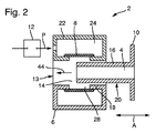
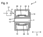
図1−4は、様々な作動状態における接続装置を概略的に示す長手方向の断面図である。接続装置2は、連結装置6および連結装置6に接続可能な接続要素10を備えている。連結装置6は供給側にあり、水あるいは洗浄および/あるいは消毒する液体などの、外科器具の洗浄されるチャネル、とりわけ内視鏡の内視鏡チャネルを洗浄および/あるいは消毒するためのすすぎ液5を供給する役割をする。
In the drawings, the same or similar types of elements and / or parts are given the same reference numerals in order to avoid reintroduction.
1-4 are longitudinal cross-sectional views schematically showing the connecting device in various operating states. The connecting
このような目的で、連結装置6、より正確には連結装置6の保持チャネル14は供給口13によってすすぎシステム50に接続されている。接続要素10の連結流路4は、外科器具の洗浄される流路に接続されている。
For this purpose, the
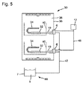
図5は、連結装置6が一体化された、同様な洗浄および消毒装置30を示している。該連結装置6は例えば、洗浄チャンバ36の後壁38に配置されている。洗浄および/あるいは消毒装置30は、洗浄されるチャネルを有する外科器具を洗浄および消毒する役割をする。例えば、内視鏡32を洗浄および/あるいは消毒する洗浄および/あるいは消毒装置30は、洗浄される内視鏡チャネル34と共に図示されている。
FIG. 5 shows a similar cleaning and disinfecting
供給口13(図1−4参照)は、すすぎ液5がその供給口13を介して連結装置6に供給可能なように、供給ライン42(図5参照)によってすすぎ液貯留槽7に接続されている。すすぎ液貯留槽7に加えて、すすぎシステム50は、複数のポンプ、センサおよびバルブ(図示なし)を備えている。
The supply port 13 (see FIG. 1-4) is connected to the rinse
接続要素10は、洗浄される内視鏡32に接続されている。よって接続要素10の接続チャネル4は、洗浄される内視鏡チャネル34と連通している。連結装置6と接続要素10との間に接続が確立した後に、チャネルは、すすぎ液貯留槽7からの洗浄および/あるいは消毒液等の、すすぎ液5ですすがれる。
The connecting
洗浄工程の最初に、接続要素10は、洗浄される内視鏡32に手動で接続されることが好ましい。使用された接続要素の連結16は、内視鏡32を保持するために、とりわけ洗浄バスケット40に取り外し可能に、あるいは恒久的に固定される。
At the beginning of the cleaning process, the connecting
洗浄される内視鏡32が入った洗浄バスケット40をユーザが洗浄および/あるいは消毒装置30の洗浄チャンバ36に落とした場合、この動作の間に、連結16が連結装置6の保持チャネル14に接続方向44に挿入される。接続装置は少なくとも保持チャネル14の縦軸方向Aに略平行である。とりわけ、保持チャネル14の断面は円形であり、連結16も同様である。
If the user drops the cleaning basket 40 containing the
連結装置6は、処理チャンバ36の後壁38に配置されていることが好ましい。連結装置6は洗浄バスケット40上の接続要素10の位置に適合するように配置されている。とりわけ、洗浄バスケット40上の接続要素2の位置と、処理チャンバ36の後壁38上の連結装置6の位置とは、洗浄バスケット40が挿入された際に、複数の連結16が関連する保持チャネル14に挿入されるように、洗浄バスケット40の複数のガイドおよびストップによって互いに調整されている。
The connecting
この動作は封止状態の抵抗を克服する必要なしに、有利に発生する。連結16の直径と保持チャネル14の直径とは、十分な許容差および間隙の寸法を考慮した上で、互いに調整されている。
This action advantageously occurs without having to overcome the sealed resistance. The diameter of the
連結16を保持チャネル14に挿入する工程は、図1−3に様々な連続状態で図示されている。
とりわけ、最終的なストップが、洗浄バスケットが端部位置に配置されている旨をユーザに通知するために設けられている。例えば接続要素10の鍔がシート6の平面側に対抗し、接続要素10に向かい合って位置するときに、該端部位置に至る。
The process of inserting the
In particular, a final stop is provided to notify the user that the cleaning basket is located at the end position. For example, when the flange of the connecting
図3に示される端部位置において、連結装置と接続要素6との間には、まだ液密の接触は確立されていない。とりわけ、端部位置に至るのに特定の力を加える必要はない。
接続要素10と連結装置6との間の液密な連結部は、油圧および/あるいは空圧で弾性封止要素を作動させることによって得られる。図示された例示的な実施形態によると、封止膜8が封止要素として設けられている。該封止膜8を作動させるために、連結装置6の外部コンポーネント22は、圧空供給器12の支援を受けて過圧が供給され得る過圧チャンバ24を備える。このような目的で、連結装置6は、圧空ライン46によって圧空供給器12に接続されている。
In the end position shown in FIG. 3, no fluid-tight contact has yet been established between the coupling device and the connecting
A fluid-tight connection between the connecting
設けられている封止膜8は弾性的に変形可能である。端部位置に達した後に、ユーザが洗浄および/あるいは消毒装置30を終了し、対応する洗浄および/あるいは消毒プログラムを選択した場合、過圧チャンバ24には、圧空供給器12の作動によって圧空Pが供給される。
The provided
膜8は、油圧および空圧によって作動され、膜8が縦軸方向Aと直交する方向へ膨張するため、膜8の領域において保持チャネル14の断面が、連結装置6を有する接続要素10の液密連結部が提供可能になるまで、あるいは提供されるまで縮小する。
The
封止要素、すなわち膜8は、過圧チャンバ24の内壁18上に、あるいは内壁18の内側に配置されている。該膜8は、空圧の作動、すなわち、過圧が過圧チャンバ24内で発生したときに、封止台座が膜8と接続要素10の連結16の外側20との間に確立するように、膨張可能である。連結装置6の外側コンポーネント22は、保持チャネル14の周長に沿って延出する環状の空隙28を備えている。これは保持チャネル14と過圧チャンバ24との間に延出する内壁18の環状の間断から発生している。環状の空隙28は、封止要素として弾性封止膜8によって封止されている。過圧チャンバ24には過圧が供給され、封止膜8は、確実な封止台座が設けられるように環状の空隙28を通して膨らむ。この状況が概略的に図4に示されている。
The sealing element, ie the
別の例示的な実施形態(図示なし)によると、環状あるいは管状の封止が設けられており、該封止も内壁18上に設けられ、保持チャネル14の内周に完全に沿って延出している。この例示的な実施形態において、外側コンポーネント22の内側の過圧チャンバ24は省略可能である。管状の封止の内側チャンバは、過圧チャンバ24の技術的な機能を想定している。この例示的な実施形態によると、内壁18はとりわけ管状の封止を受け入れ、保持する手段、例えば、周囲の溝を備えている。圧力のない状態において、このような管状の封止は、内壁18の内側に対抗して平坦に配置されている。管状の封止に圧力が供給されると、とりわけ、その周囲が大きくなり、封止と接続要素10の連結16の外側20との間に封止台座が得られるように、膨張する。
According to another exemplary embodiment (not shown), an annular or tubular seal is provided, which is also provided on the
圧空Pが連結16の過圧チャンバ24へと供給された後、圧空Pの供給圧力レベルは、圧空供給器12をオンあるいはオフに切り替えることによって変えられるか、あるいは、洗浄・消毒工程の間、保持される。このような目的で、過圧チャンバ24内の圧力は長時間測定され、対応するセンサ(図示なし)が設けられている。過圧チャンバ24の所望の圧力は、所定の基準値と比較することによって保持される。
After the compressed air P is supplied to the
これによって、洗浄および/あるいは消毒工程の間、封止台座が膜8と接続要素6の外側20との間に確実に存在する。洗浄および/あるいは消毒工程が終わった後に、連結装置6が接続要素10を解除するように、圧空Pは過圧チャンバ24から排出される。
This ensures that a sealing pedestal exists between the
封止要素の破損を検出するために、洗浄および/あるいは消毒装置30は、とりわけ圧空Pを過圧チャンバ24へ、ある供給圧力レベルで供給するよう構成されており、該供給圧力レベルは、圧空供給器12をオンあるいはオフに切り替えることによって変えられる。当該圧力は過圧チャンバ24への入口、あるいは過圧チャンバ24の供給ライン内で、第1の設定可能な時間の間測定される。その後、供給圧力レベルは段階的に変えられる。過圧チャンバ24の封止は、供給圧力レベルの変化に対して測定されたステップ応答を参照して、該ステップ応答を分析することによって検知される。
In order to detect a breakage of the sealing element, the cleaning and / or
この分析は、とりわけ、静圧を過圧チャンバ24に設定可能な第1の値と比較することを備える。更に、この分析は、とりわけ、第2の設定可能な時間の間に測定された圧力の積分を形成すること、および過圧チャンバ24に設定可能な第2の値と比較することを備える。加えて、該分析は、とりわけ、上昇を決定することおよび/あるいは時間の間に測定された圧力の二次導関数を形成することを備える。最後に、当該分析は、とりわけ、ステップ応答として測定された圧力の振動の継続時間、振幅および/あるいは波長を分析することを備える。
This analysis comprises, inter alia, comparing the static pressure with a first value that can be set in the
圧力の降下が特定の閾値を超えた場合、このことは封止要素の欠陥、とりわけ、封止膜8に欠陥があることを示唆していると考えられる。洗浄および/あるいは消毒装置30は、とりわけ、封止要素の点検あるいは交換を促す、対応するエラーあるいは通知信号を出力するよう構成されている。
If the pressure drop exceeds a certain threshold, this is thought to indicate a defect in the sealing element, in particular a defect in the
更に、接続要素10の連結16が保持チャネル14に存在するかしないかを、封止膜8の弾性反応を参照して決定することが可能である。過圧チャンバ24の内側の圧力が変化する場合、封止膜8は連結16が保持チャネル14内に存在するか否かによって、異なる弾性作用を見せる。
Furthermore, it is possible to determine whether or not the
例えば、連結16が封止膜8に対向力を及ぼし、更に弾性変形あるいは膨張に利用可能な容積を制限する。とりわけ、上昇および/あるいは時間中に測定された圧力の二次導関数の形成を分析することによって、連結16が保持チャネル14に配置されているかを決定することが可能である。更に、内側の圧力における変化に対するステップ応答として測定された圧力の振動の継続時間、振幅および/あるいは波長の分析することは、このため有益である。
For example, the
図から把握されるものも含め、挙げられた単独の特徴および他の特徴と組合せて開示されている個々の特徴の全ては、単独で、および組合せで、本発明の本質的な要素として考慮される。本発明による実施形態は個々の特徴、あるいはいくつかの特徴の組合せによって実現可能である。本発明の範囲において「とりわけ」あるいは「好ましくは」という語を用いて示された特徴は、任意の特徴であることが好ましい。 All of the individual features disclosed, including those taken from the figures, in combination with the single feature and other features, are considered alone and in combination as essential elements of the invention. The Embodiments according to the present invention can be realized by individual features or a combination of several features. Features indicated using the words “among others” or “preferably” within the scope of the present invention are preferably arbitrary features.
2…接続装置、4…接続チャネル、5…すすぎ液、6…連結装置、7…すすぎ液貯留槽、8…封止膜、10…接続要素、12…圧空供給器、13…供給口、14…保持チャネル、16…連結、18…内壁、20…外側、22…外側コンポーネント、24…過圧チャンバ、26…仕切り壁、28…環状の空隙、30…洗浄および/あるいは消毒装置、32…内視鏡、34…内視鏡チャネル、36…洗浄チャンバ、38…壁、40…洗浄バスケット、42…供給ライン、44…接続装置、46…圧空ライン、50…すすぎシステム、P…圧空、A…縦軸方向
DESCRIPTION OF
Claims (10)
−前記接続要素(10)の連結(16)を前記保持チャネル(14)の前記縦軸方向(A)に沿って前記供給側連結装置(6)の前記保持チャネル(14)に導入することと、
−作動された前記封止要素が、前記縦軸方向(A)に直交する方向へ膨張することによって、前記保持チャネル(14)の前記封止要素の前記領域における断面が縮小するように、油圧および/あるいは空圧で前記封止要素を作動させるべく、過圧下で前記封止要素に油圧および/あるいは空圧流体を供給することによって、前記封止要素に過圧を加えることと、
−前記保持チャネル(14)から前記接続チャネル(4)を介して流出する前記すすぎ液が、前記洗浄される外科器具の前記チャネルを洗浄および消毒するため、とりわけ内視鏡(32)の内視鏡チャネル(34)を洗浄および/あるいは消毒するために利用可能となるように、すすぎ液(5)を前記保持チャネル(14)に供給することと、
−前記接続要素(10)が前記連結装置(6)から解放されるように、前記流体による前記封止要素に対する前記過圧作用を減らすべく、前記油圧および/あるいは空圧流体の前記圧力を減圧すること、とのステップを備えることを特徴とする方法。 The operation method of the cleaning and / or disinfection device (30) according to claim 6,
Introducing the connection (16) of the connecting element (10) into the holding channel (14) of the supply side connecting device (6) along the longitudinal direction (A) of the holding channel (14); ,
Hydraulic pressure so that the actuated sealing element expands in a direction perpendicular to the longitudinal axis (A), thereby reducing the cross section in the region of the sealing element of the retaining channel (14); Applying overpressure to the sealing element by supplying hydraulic and / or pneumatic fluid to the sealing element under overpressure to operate the sealing element with air pressure; and / or
The endoscope (32), in particular, for the rinsing liquid flowing out of the holding channel (14) via the connecting channel (4) to clean and disinfect the channel of the surgical instrument to be cleaned. Supplying a rinsing liquid (5) to the retention channel (14) such that it can be used to clean and / or disinfect the mirror channel (34);
Reducing the pressure of the hydraulic and / or pneumatic fluid in order to reduce the overpressure action on the sealing element by the fluid such that the connecting element (10) is released from the coupling device (6); And a step comprising the steps of:
−前記過圧チャンバ(24)における時間依存圧力を測定し、前記測定された圧力を設定可能な目標圧力と比較することであって、前記圧空供給器(12)をオンあるいはオフに切り替えることによって、前記目標圧力は前記洗浄および/あるいは消毒工程の継続時間保持される、測定および比較を行うこととの追加のステップを備えていることを特徴とする、請求項7に記載の方法。 Supplying pressurized air (P) to an overpressure chamber (24) at least partly surrounded by the sealing element, the supply pressure level of the compressed air (P) turning on the pneumatic supply (12) Or supplying compressed air (P), which can be changed by switching off;
Measuring the time-dependent pressure in the overpressure chamber (24) and comparing the measured pressure with a settable target pressure, by switching the pneumatic supply (12) on or off 8. The method according to claim 7, characterized in that the target pressure is maintained for the duration of the cleaning and / or disinfection process, with the additional step of measuring and comparing.
Applications Claiming Priority (3)
| Application Number | Priority Date | Filing Date | Title |
|---|---|---|---|
| DE102014206020.6A DE102014206020A1 (en) | 2014-03-31 | 2014-03-31 | Connecting device, cleaning and / or disinfecting device and method for operating the same |
| DE102014206020.6 | 2014-03-31 | ||
| PCT/EP2015/055692 WO2015150080A1 (en) | 2014-03-31 | 2015-03-18 | Connecting device, cleaning and/or disinfecting device, and method for the operation thereof |
Publications (2)
| Publication Number | Publication Date |
|---|---|
| JP2017509436A true JP2017509436A (en) | 2017-04-06 |
| JP2017509436A5 JP2017509436A5 (en) | 2017-08-03 |
Family
ID=52774192
Family Applications (1)
| Application Number | Title | Priority Date | Filing Date |
|---|---|---|---|
| JP2016560519A Withdrawn JP2017509436A (en) | 2014-03-31 | 2015-03-18 | Connection device, cleaning and / or disinfection device and method of operation thereof |
Country Status (6)
| Country | Link |
|---|---|
| US (1) | US10085817B2 (en) |
| EP (1) | EP3125741B1 (en) |
| JP (1) | JP2017509436A (en) |
| CN (1) | CN105939649A (en) |
| DE (1) | DE102014206020A1 (en) |
| WO (1) | WO2015150080A1 (en) |
Cited By (1)
| Publication number | Priority date | Publication date | Assignee | Title |
|---|---|---|---|---|
| JP2020531171A (en) * | 2017-08-24 | 2020-11-05 | エルベ ユーエスエー, インコーポレイテッド | Equipment for improved visualization of endoscopic procedures |
Families Citing this family (4)
| Publication number | Priority date | Publication date | Assignee | Title |
|---|---|---|---|---|
| DE102016212672B3 (en) * | 2016-07-12 | 2017-07-06 | Olympus Winter & Ibe Gmbh | Device for checking the tightness of a surgical instrument, treatment device for the preparation of surgical instruments and use of a swellable material body |
| CN109475286B (en) * | 2016-09-21 | 2021-06-18 | 奥林巴斯株式会社 | Endoscope regeneration processor and endoscope water removal method |
| DE102017112169B3 (en) * | 2017-06-01 | 2018-07-26 | Olympus Winter & Ibe Gmbh | Preparation device for endoscopes |
| CN110811738A (en) * | 2019-11-29 | 2020-02-21 | 四川大学 | Hemostasis compressor for cardiology |
Family Cites Families (6)
| Publication number | Priority date | Publication date | Assignee | Title |
|---|---|---|---|---|
| US4042248A (en) * | 1976-09-16 | 1977-08-16 | General Motors Corporation | High pressure shaft seals |
| JPH028565A (en) * | 1988-01-11 | 1990-01-12 | Taiho Kogyo Co Ltd | Lip seal device |
| DE3737121A1 (en) * | 1987-11-02 | 1989-05-11 | Alexander Staeblein | Controllable sealing system for catheter and instrument insertion kits |
| US5931647A (en) * | 1993-11-23 | 1999-08-03 | Sarcos, Inc. | Volumetric pump with bi-directional piston seal |
| JP2004135946A (en) * | 2002-10-18 | 2004-05-13 | Olympus Corp | Apparatus for washing and disinfecting endoscope |
| JP5220435B2 (en) * | 2008-02-20 | 2013-06-26 | オリンパスメディカルシステムズ株式会社 | Cleaning tube and endoscope cleaning / disinfecting device |
-
2014
- 2014-03-31 DE DE102014206020.6A patent/DE102014206020A1/en not_active Withdrawn
-
2015
- 2015-03-18 EP EP15712834.9A patent/EP3125741B1/en active Active
- 2015-03-18 WO PCT/EP2015/055692 patent/WO2015150080A1/en active Application Filing
- 2015-03-18 CN CN201580006252.8A patent/CN105939649A/en active Pending
- 2015-03-18 JP JP2016560519A patent/JP2017509436A/en not_active Withdrawn
-
2016
- 2016-09-23 US US15/274,807 patent/US10085817B2/en not_active Expired - Fee Related
Cited By (2)
| Publication number | Priority date | Publication date | Assignee | Title |
|---|---|---|---|---|
| JP2020531171A (en) * | 2017-08-24 | 2020-11-05 | エルベ ユーエスエー, インコーポレイテッド | Equipment for improved visualization of endoscopic procedures |
| JP7269223B2 (en) | 2017-08-24 | 2023-05-08 | エルベ ユーエスエー, インコーポレイテッド | Apparatus for improved visualization of endoscopic procedures |
Also Published As
| Publication number | Publication date |
|---|---|
| WO2015150080A1 (en) | 2015-10-08 |
| EP3125741A1 (en) | 2017-02-08 |
| US20170007357A1 (en) | 2017-01-12 |
| EP3125741B1 (en) | 2020-06-10 |
| DE102014206020A1 (en) | 2015-10-01 |
| CN105939649A (en) | 2016-09-14 |
| US10085817B2 (en) | 2018-10-02 |
Similar Documents
| Publication | Publication Date | Title |
|---|---|---|
| JP2017509436A (en) | Connection device, cleaning and / or disinfection device and method of operation thereof | |
| RU2431503C2 (en) | Method of determining adequate connection of endoscope test channel | |
| JP5295493B2 (en) | Apparatus and method for imparting flow to a flow path in an endoscope | |
| JP5165479B2 (en) | Endoscope cleaning disinfection device | |
| JP2006334405A (en) | Connector for endoscope reprocessing device reduced in occurrence of clogging state | |
| JP2004202247A (en) | Method for detecting proper binding of fixture to channel of endoscope | |
| WO2015174231A1 (en) | Endoscope connector | |
| MXPA06003584A (en) | Automated endoscope reprocessor connection integrity testing via liquid suction. | |
| JP2017509436A5 (en) | ||
| JP4441550B2 (en) | Endoscope cleaning and disinfection device | |
| JP2006006565A (en) | Endoscope washing and disinfecting device | |
| JP3205321U (en) | Endoscope reprocessor | |
| EP3162278B1 (en) | Endoscope reprocessor | |
| JP5843990B1 (en) | Pre-cleaning kit for surgery support robot instrument | |
| WO2017033483A1 (en) | Endoscope reprocessor and leak test method for endoscope reprocessor | |
| JP6415887B2 (en) | Endoscope leak tester and endoscope reprocessing device | |
| JP6602602B2 (en) | Endoscope reprocessor and driving method of endoscope reprocessor | |
| JP6033514B1 (en) | Endoscope reprocessor and endoscope reprocessor leak test method | |
| JP4801286B2 (en) | Autoclave equipment | |
| JP6010271B1 (en) | Endoscope reprocessor | |
| US20240016375A1 (en) | Medical Device Reprocessor With Multi-Source Dispenser | |
| KR102026105B1 (en) | Semi-automatic endoscope cleaning system | |
| US20220313073A1 (en) | Fluid distributor for a reprocessing device for reprocessing a surgical instrument | |
| US20220330794A1 (en) | Endoscope reprocessor and actuation method for endoscope reprocessor | |
| JP2011087737A (en) | Holder for washing tubular medical instrument and washing method using the same |
Legal Events
| Date | Code | Title | Description |
|---|---|---|---|
| A521 | Written amendment |
Free format text: JAPANESE INTERMEDIATE CODE: A523 Effective date: 20170621 |
|
| A621 | Written request for application examination |
Free format text: JAPANESE INTERMEDIATE CODE: A621 Effective date: 20170621 |
|
| A761 | Written withdrawal of application |
Free format text: JAPANESE INTERMEDIATE CODE: A761 Effective date: 20171017 |
|
| A521 | Written amendment |
Free format text: JAPANESE INTERMEDIATE CODE: A821 Effective date: 20171017 |