JP2017509106A - Electrical conductor and method of forming electrical conductor - Google Patents
Electrical conductor and method of forming electrical conductor Download PDFInfo
- Publication number
- JP2017509106A JP2017509106A JP2016545849A JP2016545849A JP2017509106A JP 2017509106 A JP2017509106 A JP 2017509106A JP 2016545849 A JP2016545849 A JP 2016545849A JP 2016545849 A JP2016545849 A JP 2016545849A JP 2017509106 A JP2017509106 A JP 2017509106A
- Authority
- JP
- Japan
- Prior art keywords
- conductive material
- electrical conductor
- carbon
- graphite intercalation
- layer
- Prior art date
- Legal status (The legal status is an assumption and is not a legal conclusion. Google has not performed a legal analysis and makes no representation as to the accuracy of the status listed.)
- Granted
Links
- 239000004020 conductor Substances 0.000 title claims abstract description 119
- 238000000034 method Methods 0.000 title claims description 30
- OKTJSMMVPCPJKN-UHFFFAOYSA-N Carbon Chemical compound [C] OKTJSMMVPCPJKN-UHFFFAOYSA-N 0.000 claims abstract description 94
- 229910052799 carbon Inorganic materials 0.000 claims abstract description 45
- 238000009830 intercalation Methods 0.000 claims abstract description 39
- 229910002804 graphite Inorganic materials 0.000 claims abstract description 38
- 239000010439 graphite Substances 0.000 claims abstract description 38
- 230000002687 intercalation Effects 0.000 claims abstract description 38
- 150000001875 compounds Chemical class 0.000 claims abstract description 37
- 239000002245 particle Substances 0.000 claims abstract description 36
- 239000011159 matrix material Substances 0.000 claims description 19
- 239000000463 material Substances 0.000 claims description 15
- 229910021389 graphene Inorganic materials 0.000 claims description 11
- RYGMFSIKBFXOCR-UHFFFAOYSA-N Copper Chemical compound [Cu] RYGMFSIKBFXOCR-UHFFFAOYSA-N 0.000 claims description 9
- 229910052802 copper Inorganic materials 0.000 claims description 9
- 239000010949 copper Substances 0.000 claims description 9
- BQCADISMDOOEFD-UHFFFAOYSA-N Silver Chemical compound [Ag] BQCADISMDOOEFD-UHFFFAOYSA-N 0.000 claims description 7
- 229910052782 aluminium Inorganic materials 0.000 claims description 7
- XAGFODPZIPBFFR-UHFFFAOYSA-N aluminium Chemical compound [Al] XAGFODPZIPBFFR-UHFFFAOYSA-N 0.000 claims description 7
- PCHJSUWPFVWCPO-UHFFFAOYSA-N gold Chemical compound [Au] PCHJSUWPFVWCPO-UHFFFAOYSA-N 0.000 claims description 7
- 229910052737 gold Inorganic materials 0.000 claims description 7
- 239000010931 gold Substances 0.000 claims description 7
- 229910052709 silver Inorganic materials 0.000 claims description 7
- 239000004332 silver Substances 0.000 claims description 7
- 239000000835 fiber Substances 0.000 claims description 4
- WKBOTKDWSSQWDR-UHFFFAOYSA-N Bromine atom Chemical compound [Br] WKBOTKDWSSQWDR-UHFFFAOYSA-N 0.000 claims description 2
- OYPRJOBELJOOCE-UHFFFAOYSA-N Calcium Chemical compound [Ca] OYPRJOBELJOOCE-UHFFFAOYSA-N 0.000 claims description 2
- ZLMJMSJWJFRBEC-UHFFFAOYSA-N Potassium Chemical compound [K] ZLMJMSJWJFRBEC-UHFFFAOYSA-N 0.000 claims description 2
- GDTBXPJZTBHREO-UHFFFAOYSA-N bromine Substances BrBr GDTBXPJZTBHREO-UHFFFAOYSA-N 0.000 claims description 2
- 229910052794 bromium Inorganic materials 0.000 claims description 2
- 229910052791 calcium Inorganic materials 0.000 claims description 2
- 239000011575 calcium Substances 0.000 claims description 2
- 238000007772 electroless plating Methods 0.000 claims description 2
- 238000009713 electroplating Methods 0.000 claims description 2
- 238000010884 ion-beam technique Methods 0.000 claims description 2
- 238000007747 plating Methods 0.000 claims description 2
- 229910052700 potassium Inorganic materials 0.000 claims description 2
- 239000011591 potassium Substances 0.000 claims description 2
- 238000004544 sputter deposition Methods 0.000 claims description 2
- 239000010410 layer Substances 0.000 claims 14
- 239000012790 adhesive layer Substances 0.000 claims 2
- 238000005137 deposition process Methods 0.000 claims 1
- 239000011241 protective layer Substances 0.000 claims 1
- 239000000758 substrate Substances 0.000 claims 1
- 238000007704 wet chemistry method Methods 0.000 claims 1
- 238000004519 manufacturing process Methods 0.000 description 12
- 238000012423 maintenance Methods 0.000 description 11
- 230000006870 function Effects 0.000 description 8
- 229910052751 metal Inorganic materials 0.000 description 7
- 239000002184 metal Substances 0.000 description 7
- 238000010586 diagram Methods 0.000 description 6
- 230000008569 process Effects 0.000 description 5
- 230000007423 decrease Effects 0.000 description 2
- 239000007769 metal material Substances 0.000 description 2
- 238000012986 modification Methods 0.000 description 2
- 230000004048 modification Effects 0.000 description 2
- 230000008520 organization Effects 0.000 description 2
- 230000004580 weight loss Effects 0.000 description 2
- VYZAMTAEIAYCRO-UHFFFAOYSA-N Chromium Chemical compound [Cr] VYZAMTAEIAYCRO-UHFFFAOYSA-N 0.000 description 1
- -1 GIC 202 Chemical class 0.000 description 1
- RTAQQCXQSZGOHL-UHFFFAOYSA-N Titanium Chemical compound [Ti] RTAQQCXQSZGOHL-UHFFFAOYSA-N 0.000 description 1
- 230000009471 action Effects 0.000 description 1
- 239000000956 alloy Substances 0.000 description 1
- 238000013475 authorization Methods 0.000 description 1
- 238000005234 chemical deposition Methods 0.000 description 1
- 238000005229 chemical vapour deposition Methods 0.000 description 1
- 229910052804 chromium Inorganic materials 0.000 description 1
- 239000011651 chromium Substances 0.000 description 1
- 239000002131 composite material Substances 0.000 description 1
- 238000013461 design Methods 0.000 description 1
- 238000009792 diffusion process Methods 0.000 description 1
- 239000002019 doping agent Substances 0.000 description 1
- 230000007613 environmental effect Effects 0.000 description 1
- 238000004299 exfoliation Methods 0.000 description 1
- 239000000446 fuel Substances 0.000 description 1
- 230000010354 integration Effects 0.000 description 1
- 229910001092 metal group alloy Inorganic materials 0.000 description 1
- 230000003647 oxidation Effects 0.000 description 1
- 238000007254 oxidation reaction Methods 0.000 description 1
- 229910052719 titanium Inorganic materials 0.000 description 1
- 239000010936 titanium Substances 0.000 description 1
Images


Classifications
-
- H—ELECTRICITY
- H01—ELECTRIC ELEMENTS
- H01B—CABLES; CONDUCTORS; INSULATORS; SELECTION OF MATERIALS FOR THEIR CONDUCTIVE, INSULATING OR DIELECTRIC PROPERTIES
- H01B13/00—Apparatus or processes specially adapted for manufacturing conductors or cables
- H01B13/0026—Apparatus for manufacturing conducting or semi-conducting layers, e.g. deposition of metal
-
- H—ELECTRICITY
- H01—ELECTRIC ELEMENTS
- H01B—CABLES; CONDUCTORS; INSULATORS; SELECTION OF MATERIALS FOR THEIR CONDUCTIVE, INSULATING OR DIELECTRIC PROPERTIES
- H01B1/00—Conductors or conductive bodies characterised by the conductive materials; Selection of materials as conductors
- H01B1/02—Conductors or conductive bodies characterised by the conductive materials; Selection of materials as conductors mainly consisting of metals or alloys
-
- H—ELECTRICITY
- H01—ELECTRIC ELEMENTS
- H01B—CABLES; CONDUCTORS; INSULATORS; SELECTION OF MATERIALS FOR THEIR CONDUCTIVE, INSULATING OR DIELECTRIC PROPERTIES
- H01B1/00—Conductors or conductive bodies characterised by the conductive materials; Selection of materials as conductors
- H01B1/04—Conductors or conductive bodies characterised by the conductive materials; Selection of materials as conductors mainly consisting of carbon-silicon compounds, carbon or silicon
-
- H—ELECTRICITY
- H01—ELECTRIC ELEMENTS
- H01B—CABLES; CONDUCTORS; INSULATORS; SELECTION OF MATERIALS FOR THEIR CONDUCTIVE, INSULATING OR DIELECTRIC PROPERTIES
- H01B5/00—Non-insulated conductors or conductive bodies characterised by their form
- H01B5/14—Non-insulated conductors or conductive bodies characterised by their form comprising conductive layers or films on insulating-supports
Abstract
電気導体が提供される。電気導体は、黒鉛層間化合物、及び黒鉛層間化合物の少なくとも一部の上に延在する導電性材料の少なくとも1つの層を含む。黒鉛層間化合物は、炭素系粒子、及び炭素系粒子内にインターカレートされた複数のゲスト分子を含む。【選択図】図1An electrical conductor is provided. The electrical conductor includes a graphite intercalation compound and at least one layer of conductive material extending over at least a portion of the graphite intercalation compound. The graphite intercalation compound includes carbon-based particles and a plurality of guest molecules intercalated in the carbon-based particles. [Selection] Figure 1
Description
本開示の分野は、概して、電気導体に関し、より具体的には、黒鉛層間化合物から少なくとも部分的に形成された電気導体に関する。 The field of the disclosure relates generally to electrical conductors, and more specifically to electrical conductors formed at least partially from graphite intercalation compounds.
少なくとも一部の既知の用途においては、電力、電流、及び電気/電子信号は、典型的に、ワイヤ又はケーブルを通して伝導される。一般的に、既知の電線又はケーブルは、導体コア、及び導体コアの周囲に配置された絶縁ジャケットを含む。少なくとも一部の既知の導体コアは、銅、銀、金、及びアルミニウムなどの材料から製作される。これらの既知の材料は望ましい導電率を有するが、既知の金属電気導体と少なくとも同等の導電率を有する軽量化された電気導体を開発し、数多くの既知の用途において軽量化を行うことが継続的な目標である。例えば、航空宇宙産業では、航空機の軽量化は、典型的に、燃料効率の向上及び/又はペイロード容量の増大をもたらす。 In at least some known applications, power, current, and electrical / electronic signals are typically conducted through wires or cables. In general, known electrical wires or cables include a conductor core and an insulating jacket disposed around the conductor core. At least some known conductor cores are fabricated from materials such as copper, silver, gold, and aluminum. While these known materials have the desired conductivity, we continue to develop lighter electrical conductors that have at least the same electrical conductivity as known metal electrical conductors and to reduce weight in many known applications. Goal. For example, in the aerospace industry, lighter aircraft typically results in improved fuel efficiency and / or increased payload capacity.
同等の導電率を有する軽量化された電気導体を開発する少なくとも1つの既知の試みには、導電性の黒鉛層間化合物を形成することがある。インターカレーションは、黒鉛状炭素の複数のグラフェン層の間にゲスト分子又は原子を導入するプロセスである。より具体的には、少なくとも一部の既知のプロセスでは、黒鉛状炭素内の隣接する複数のグラフェン層間の比較的弱い接合強度に起因する拡散作用を介して、複数のグラフェン層の間に「ドーパント」ゲスト分子又は原子が効果的に導入される。同じ大きさの金属電気導体と比較したとき、黒鉛層間化合物は、望ましい導電率を有し、軽量であるが、一般的に壊れやすく、上昇温度に露出されたときにグラフェン層の剥離を起こしやすい。更に、ゲスト分子又は原子で黒鉛状炭素をインターカレートすることは、一般的に、黒鉛状炭素の面内導電率を増大させるのみであり、面に対して垂直な黒鉛状炭素の導電率は減少する。 At least one known attempt to develop a lighter electrical conductor with comparable conductivity is to form a conductive graphite intercalation compound. Intercalation is the process of introducing guest molecules or atoms between multiple graphene layers of graphitic carbon. More specifically, at least in some known processes, the “dopant” between the graphene layers is affected by a diffusion action due to the relatively weak bond strength between adjacent graphene layers in graphitic carbon. "Guest molecules or atoms are effectively introduced. When compared to metallic electrical conductors of the same size, graphite intercalation compounds have desirable conductivity and are lightweight, but generally fragile and prone to exfoliation of the graphene layer when exposed to elevated temperatures . Furthermore, intercalating graphitic carbon with guest molecules or atoms generally only increases the in-plane conductivity of graphitic carbon, and the conductivity of graphitic carbon perpendicular to the plane is Decrease.
本開示の1つの態様では、電気導体が提供される。電気導体は、黒鉛層間化合物、及び黒鉛層間化合物の少なくとも一部の上に延在する導電性材料の少なくとも1つの層を含む。黒鉛層間化合物は、炭素系粒子、及び炭素系粒子内にインターカレートされた複数のゲスト分子を含む。 In one aspect of the present disclosure, an electrical conductor is provided. The electrical conductor includes a graphite intercalation compound and at least one layer of conductive material extending over at least a portion of the graphite intercalation compound. The graphite intercalation compound includes carbon-based particles and a plurality of guest molecules intercalated in the carbon-based particles.
本開示の別の態様では、電気導体が提供される。電気導体は、導電性材料のベースマトリックス及びベースマトリックス内に分散された複数の黒鉛層間化合物を含む。複数の黒鉛層間化合物は、それぞれ、炭素系粒子、及び炭素系粒子内にインターカレートされた複数のゲスト分子を含む。 In another aspect of the present disclosure, an electrical conductor is provided. The electrical conductor includes a base matrix of conductive material and a plurality of graphite intercalation compounds dispersed within the base matrix. Each of the plurality of graphite intercalation compounds includes carbon-based particles and a plurality of guest molecules intercalated in the carbon-based particles.
本開示の更に別の態様では、電気導体を形成する方法が提供される。この方法は、炭素系粒子及び炭素系粒子内にインターカレートされた複数のゲスト分子を含む黒鉛層間化合物を設けることを含む。この方法は、黒鉛層間化合物の少なくとも一部の上に導電性材料を延在させることを更に含む。導電性材料は、導電性材料の少なくとも1つの層又は導電性材料のベースマトリックスの形態にある。 In yet another aspect of the present disclosure, a method of forming an electrical conductor is provided. The method includes providing a carbon-based particle and a graphite intercalation compound including a plurality of guest molecules intercalated within the carbon-based particle. The method further includes extending a conductive material over at least a portion of the graphite intercalation compound. The conductive material is in the form of at least one layer of conductive material or a base matrix of conductive material.
更に、本開示は、以下の条項による実施形態を含む。 Furthermore, the present disclosure includes embodiments according to the following clauses.
条項1
導電性材料のベースマトリックス及び前記ベースマトリックス内に分散された複数の黒鉛層間化合物を含む電気導体であって、前記複数の黒鉛層間化合物が、それぞれ、炭素系粒子、及び前記炭素系粒子内にインターカレートされた複数のゲスト分子を含む、電気導体。
Article 1
An electrical conductor comprising a base matrix of a conductive material and a plurality of graphite intercalation compounds dispersed in the base matrix, wherein the plurality of graphite intercalation compounds are intercalated in carbon-based particles and carbon-based particles, respectively. An electrical conductor containing a plurality of guest molecules that are calated.
条項2
複数の黒鉛層間化合物が、最大で電気導体の約70パーセントの容量を占める、条項1に記載の電気導体。
Article 2
The electrical conductor of clause 1, wherein the plurality of graphite intercalation compounds occupy up to about 70 percent capacity of the electrical conductor.
条項3
前記複数のゲスト分子が前記炭素系粒子に囲まれるように、前記ベースマトリックスが前記複数の黒鉛層間化合物の上に延在する、条項1に記載の電気導体。
Article 3
The electrical conductor of clause 1, wherein the base matrix extends over the plurality of graphite intercalation compounds such that the plurality of guest molecules are surrounded by the carbon-based particles.
条項4
前記炭素系粒子が、フレーク、プレートレット、繊維、球体、チューブ、及びロッドから選択された形状にある、条項1に記載の電気導体。
Article 4
The electrical conductor of clause 1, wherein the carbon-based particles are in a shape selected from flakes, platelets, fibers, spheres, tubes, and rods.
条項5
前記ベースマトリックスが、銅、銀、金、及びアルミニウムのうちの少なくとも1つから製作される、条項1に記載の電気導体。
Article 5
The electrical conductor of clause 1, wherein the base matrix is made from at least one of copper, silver, gold, and aluminum.
本明細書に記載された実装態様は、黒鉛層間化合物(GIC)から少なくとも部分的に形成された電気導体に関する。GICは、内部にインターカレートされた複数のゲスト分子を有する炭素系粒子から形成される。例示的な実装形態では、GICは次いで導電性材料によって囲まれ、本明細書で記載された電気導体が形成される。例えば、導電性材料は、導電性材料の少なくとも1つの層又はベースマトリックスの形態であってもよい。GICは、銅などの似たような大きさの金属電気導体に対して、約5倍の面内導電率及び約4分の1の重量を有し得る。このようにして、本明細書に記載の電気導体は、既知の金属導電性材料から形成された似たような大きさの電気導体に比べて、重量が少なく、少なくとも同等の導電率を有する。 The implementation described herein relates to an electrical conductor formed at least partially from a graphite intercalation compound (GIC). The GIC is formed from carbon-based particles having a plurality of guest molecules intercalated therein. In an exemplary implementation, the GIC is then surrounded by a conductive material to form the electrical conductors described herein. For example, the conductive material may be in the form of at least one layer of conductive material or a base matrix. A GIC can have an in-plane conductivity of about 5 times and a weight of about a quarter of a similarly sized metal electrical conductor such as copper. In this way, the electrical conductors described herein are lighter and have at least an equivalent electrical conductivity compared to similar sized electrical conductors formed from known metal conductive materials.
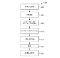
図面を参照すると、本開示の実装形態が、(図1に示す)航空機の製作及び保守方法100に照らして、且つ、(図2に示す)航空機102を通じて、説明され得る。仕様及び設計104を含む製作前段階において、航空機102のデータが製作プロセスの間に使用されてよく、且つ、機体に関連付けられる他の材料が調達106され得る。製作段階においては、航空機102のコンポーネント及びサブアセンブリの製作108とシステムインテグレーション110とが行われ、その後、航空機102はその認可及び納品112を経る。機体認可が成功裏に達成及び完遂されると、航空機102は運航114に供され得る。顧客により運航されている間、航空機102には、例えば、任意の改変、再構成、及び/又は改修などを含む、定期的且つ慣例的な定められた整備及び保守116が予定される。代替的な実行形態では、製作及び保守方法100は、航空機以外のビークルで実装され得る。
With reference to the drawings, implementations of the present disclosure may be described in the context of aircraft manufacturing and service method 100 (shown in FIG. 1) and through aircraft 102 (shown in FIG. 2). In the pre-production phase, including specifications and
航空機の製作及び/又は保守方法100に関連付けられる各部分及びプロセスは、システムインテグレータ、第三者、及び/又はオペレータ(例えば顧客)によって実施又は完了され得る。本明細書の目的のために、システムインテグレータは、限定するものではないが、任意の数の航空機製造者及び主要システムの下請業者を含んでもよく、第三者は、限定するものではないが、任意の数のベンダー、下請業者、及び供給業者を含んでもよく、且つ、オペレータは、航空会社、リース会社、軍事団体、サービス機関などであってもよい。
Each portion and process associated with aircraft manufacturing and / or
図2に示すように、方法100を通じて製作された航空機102は、複数のシステム120及び内装122を有する機体118を含み得る。高レベルのシステム120の例には、推進システム124、電気システム126、油圧システム128、及び/又は環境システム130のうちの1つ又は複数が含まれる。任意の数の他のシステムが含まれ得る。
As shown in FIG. 2,
本明細書に具現化された装置と方法は、方法100の1つ又は複数の任意の段階で採用してもよい。例えば、コンポーネント生産プロセス108に対応するコンポーネント又はサブアセンブリは、航空機102の運航中に生産されるコンポーネント又はサブアセンブリと似たような態様で作製又は製作され得る。更に、1つ又は複数の装置の実装形態、方法の実装形態、或いはそれらの組み合わせは、例えば、航空機102の組立てを実質的に効率化すること、及び/又は、航空機102の組立てのコストを削減することにより、製作段階108及び110で利用され得る。同様に、装置の実装形態、方法の実装形態、或いはそれらの組み合わせのうちの1つ又は複数は、航空機102が例えば定められた整備及び保守116において保守又は整備を受けている時に、利用され得る。
The devices and methods embodied herein may be employed at any one or more of the stages of
本明細書で使用される「航空機(aircraft)」という用語は、飛行機、無人機(UAV)、グライダー、ヘリコプター、及び/又は空域を移動する他の任意の物体を含み得るが、それらのみを含むとは限定されない。更に、代替的な実装形態では、本明細書に記載の航空機の製作及び保守方法は、任意の製作及び/又は保守作業で使用され得る。 As used herein, the term “aircraft” may include, but only includes, airplanes, unmanned aerial vehicles (UAVs), gliders, helicopters, and / or any other object moving in the airspace. It is not limited. Further, in alternative implementations, the aircraft fabrication and maintenance methods described herein may be used in any fabrication and / or maintenance operations.
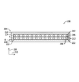
図3は、例示的な電気導体200の概略断面図である。例示的な実装形態では、電気導体200は、黒鉛層間化合物(graphite intercalation compound)(GIC)202、及びGIC202の少なくとも一部の上に延在する導電性材料の複数の層204を含む。GIC202は、炭素系粒子206及び炭素系粒子206内にインターカレートされた複数のゲスト分子208から形成される。炭素系粒子206は、電気導体200が本明細書で説明されているように機能することを可能にする任意の形状であってもよい。例示的な形状は、限定されないが、フレーク、プレートレット、繊維、球体、チューブ、及びロッドから選択される。更に、炭素系粒子206は、ほぼ平面方向210に延在するグラフェンの層212を含む高配向熱分解黒鉛などの黒鉛状炭素から製作される。
FIG. 3 is a schematic cross-sectional view of an exemplary
上述のように、ゲスト分子208は、炭素系粒子206内にインターカレートされる。より具体的には、ゲスト分子208は、炭素系粒子206の隣接するグラフェンの層212の間に位置決めされる。ゲスト分子208は、電気導体200が本明細書に記載のように機能することを可能にする任意の材料から製作してもよい。例示的な材料は、限定されないが、ブロム、カルシウム、及びカリウムを含む。
As described above, the
例示的な実装形態では、導電性材料の層204は、導電性材料の第1の層214、導電性材料の第2の層216、及び導電性材料の第3の層218を含む。第1の層214は、GIC202の少なくとも一部の上に延在し、第2の層216は、第1の層214の少なくとも一部の上に延在し、且つ第3の層218は、第2の層216の少なくとも一部の上に延在する。第1の層214、第2の層216、及び第3の層218は、それぞれ異なる機能を果たす。例えば、例示的な実装形態では、第1の層214は、第2の層216をGIC202に接着することを助け、第2の層216は、第1の層214及び第3の層218を形成するために用いられる材料よりも安価であり得る導電性材料から製作され、且つ第3の層218は、例えば、第2の層216を酸化及び/又は物理的歪みから保護することを助ける。代替的な実装形態は、電気導体200は、電気導体200が本明細書に記載のように機能することを可能にする任意の数の層204を含んでもよい。
In the exemplary implementation, the
各層204は、電気導体200が本明細書に記載のように機能することを可能にする任意の材料から製作してもよい。例示的な実装形態では、各層204は、異なる材料から製作される。第1の層214を製作するために用いられる例示的な材料は、限定されないが、クロム及びチタンを含む。第2の層216を製作するために用いられる例示的な材料は、限定されないが、銅、銀、金、及びアルミニウムを含む。第3の層218を製作するために用いられる例示的な材料は、限定されないが、銀、金、及びアルミニウムを含む。層204は、任意の適切なプロセスを通してGIC202の上に適用される。例示的なプロセスは、限定されないが、スパッタリング、イオンビームプレーティング、電気めっき、無電解めっき、湿式化学堆積、及び蒸着を含む。
Each
例示的な実装形態では、ゲスト分子208が炭素系粒子206に完全に囲まれるように、層204がGIC202の上に延在する。より具体的には、層204は、平面方向210及び平面方向210に対する法線方向220の両方においてGIC202の上に延在し、GIC202が導電性上層(図示せず)に包み込まれる。幾つかの実装形態では、法線方向220でGIC202の上に層204が延在することは、法線方向220で電気導体200内の導電率を増大させることを助ける。上述のように、炭素系粒子206内でインターカレートするゲスト分子208は、一般的に、平面方向210でGIC202の導電率を増大させるのみである。より具体的には、炭素系粒子206内でインターカレートするゲスト分子208は、隣接するグラフェン層212間の距離Dを増大させる。距離Dが増大するにつれて、法線方向220での炭素系粒子206の導電率は減少する。このように、例示的な実装形態では、複数の層204は、所与のGIC202から複数のGIC202への高い面内導電率の間で低抵抗配線経路を設け、それにより、導電性複合層(図示せず)が形成される。
In the exemplary implementation,
幾つかの実装形態では、細長い電気導体(図示せず)の形成を助けるために複数の電気導体200が相互接続され得る。例えば、細長い電気導体の形成を助けるために複数の電気導体200が物理的、化学的、及び/又は電気化学的に接合されてもよい。層204は導電性材料から形成されるため、複数の電気導体200を相互接続することは、実質的に連続的な電気導体を形成することを助ける。
In some implementations, a plurality of
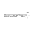
図4は、代替的な電気導体224の概略図である。例示的な実装形態では、電気導体224は、導電性材料のベースマトリックス226、及びベースマトリックス226内に分散された複数のGIC202を含む。ベースマトリックス226は、電気導体224が本明細書に記載のように機能することを可能にする任意の材料から製作される。例示的な実装形態では、ベースマトリックス226は、金属材料から製作される。本明細書で使用される「金属」という用語は、単一の金属材料又は金属合金材料を表し得る。ベースマトリックス226を製作するために用いられる例示的な材料は、限定されないが、銅、銀、金、及びアルミニウムを含む。
FIG. 4 is a schematic diagram of an alternative
GIC202は、概して、ベースマトリックス226の製作に用いられた材料よりも少ない重量、又はより大きな導電率を有するため、ベースマトリックス226内にGIC202を分散させることにより、ベースマトリックス材料のみから形成された似たような大きさの従来の電気導体よりも重量が低い電気導体224が形成される。従って、重量減少は、電気導体224内のGIC202の容量パーセントの関数である。電気導体224が本明細書に記載のように機能することを可能にする電気導体224内のGIC202の任意の容量パーセントが選択されてもよい。例示的な実装形態では、電気導体224内のGIC202の容量パーセントは、最大で電気導体224の約70パーセントの容量を占め、これにより、銅などの従来の電気導体に比べたとき、電気導体224が少なくとも約50パーセント重量減少する結果となり得る。
Because
図5は、電気導体200などの電気導体を形成する方法300を示すフロー図である。方法300は、GIC202などの黒鉛層間化合物を設けること(302)を含み、黒鉛層間化合物は、炭素系粒子206などの炭素系粒子、及び炭素系粒子内にインターカレートされたゲスト分子208などの複数のゲスト分子を含む。方法300は、黒鉛層間化合物の少なくとも一部の上に導電性材料の層204などの導電性材料を延在させること(304)を更に含む。導電性材料は、導電性材料の少なくとも1つの層又は導電性材料の、ベースマトリックス226などのベースマトリックスの形態にある。
FIG. 5 is a flow diagram illustrating a
本明細書に記載の実装形態は、似たような大きさの純粋金属の電気導体に対して、重量が少なく、且つ少なくとも同等の導電率を有する電気導体を含む。より具体的には、本明細書に記載の電気導体は、少なくとも部分的に黒鉛層間化合物から形成されている。上述のように、黒鉛層間化合物は、銅製電気導体などの純粋金属の電気導体に対して、約5倍の導電率及び約4分の1の重量を有し得る。このようにして、本明細書に記載の電気導体は、既知の金属導電性材料から形成された似たような大きさの電気導体に比べて、重量が少なく、少なくとも同等の導電率を有する。 Implementations described herein include electrical conductors that are light in weight and have at least an equivalent conductivity relative to similarly sized pure metal electrical conductors. More specifically, the electrical conductor described herein is at least partially formed from a graphite intercalation compound. As mentioned above, the graphite intercalation compound can have a conductivity of about 5 times and a weight of about a quarter of a pure metal electrical conductor, such as a copper electrical conductor. In this way, the electrical conductors described herein are lighter and have at least an equivalent electrical conductivity compared to similar sized electrical conductors formed from known metal conductive materials.
ここに記載した説明では、ベストモードを含む様々な実装形態を開示し、且つ当業者が任意のデバイス及びシステムの作成及び使用、並びに組込まれた任意の方法の実行を含め、様々な実装形態を実施することを可能にするために実施例を使用している。本開示の特許可能な範囲は特許請求の範囲によって定義されており、当業者であれば想起される他の実施例も含み得る。このような他の実施例は、それらが特許請求の範囲の文言と異ならない構造的要素を有する場合、或いは、それらが特許請求の範囲の文言とわずかに異なる均等な構造的要素を含む場合、特許請求の範囲の範囲内にあることが意図されている。 The description provided herein discloses various implementations, including the best mode, and includes various implementations, including the creation and use of any device and system, and the implementation of any embedded method. Examples are used to allow implementation. The patentable scope of the disclosure is defined by the claims, and may include other examples that occur to those skilled in the art. Such other embodiments may include structural elements that do not differ from the language of the claims, or if they include equivalent structural elements that are slightly different from the language of the claims, It is intended to be within the scope of the claims.
Claims (15)
炭素系粒子、及び
前記炭素系粒子内にインターカレートされた複数のゲスト分子を含む黒鉛層間化合物、並びに
前記黒鉛層間化合物の少なくとも一部の上に延在する導電性材料の少なくとも1つの層
を含む電気導体。 A graphite intercalation compound,
Carbon-based particles, and a graphite intercalation compound including a plurality of guest molecules intercalated in the carbon-based particles, and at least one layer of a conductive material extending on at least a part of the graphite intercalation compounds Including electrical conductors.
黒鉛層間化合物を設けることであって、前記黒鉛層間化合物が、炭素系粒子及び前記炭素系粒子内にインターカレートされた複数のゲスト分子を含む、設けること、並びに
前記黒鉛層間化合物の少なくとも一部の上に導電性材料を延在させることであって、前記導電性材料が、導電性材料の少なくとも1つの層又は導電性材料のベースマトリックスの形態にある、延在させること
を含む方法。 A method of forming an electrical conductor, comprising:
Providing a graphite intercalation compound, wherein the graphite intercalation compound comprises carbon-based particles and a plurality of guest molecules intercalated in the carbon-based particles, and at least a part of the graphite intercalation compounds Extending a conductive material over the substrate, wherein the conductive material is in the form of at least one layer of conductive material or a base matrix of conductive material.
Applications Claiming Priority (3)
| Application Number | Priority Date | Filing Date | Title |
|---|---|---|---|
| US14/151,229 | 2014-01-09 | ||
| US14/151,229 US20150194241A1 (en) | 2014-01-09 | 2014-01-09 | Electrical conductors and methods of forming thereof |
| PCT/US2014/055570 WO2015105537A1 (en) | 2014-01-09 | 2014-09-15 | Electrical conductors and methods of forming thereof |
Publications (2)
| Publication Number | Publication Date |
|---|---|
| JP2017509106A true JP2017509106A (en) | 2017-03-30 |
| JP6466459B2 JP6466459B2 (en) | 2019-02-06 |
Family
ID=51660606
Family Applications (1)
| Application Number | Title | Priority Date | Filing Date |
|---|---|---|---|
| JP2016545849A Active JP6466459B2 (en) | 2014-01-09 | 2014-09-15 | Electrical conductor and method of forming electrical conductor |
Country Status (5)
| Country | Link |
|---|---|
| US (1) | US20150194241A1 (en) |
| EP (1) | EP3092652B1 (en) |
| JP (1) | JP6466459B2 (en) |
| CN (1) | CN105706179B (en) |
| WO (1) | WO2015105537A1 (en) |
Families Citing this family (8)
| Publication number | Priority date | Publication date | Assignee | Title |
|---|---|---|---|---|
| WO2017122137A1 (en) * | 2016-01-11 | 2017-07-20 | King Abdullah University Of Science And Technology | Bromine intercalated graphite for lightweight composite conductors |
| US10939550B2 (en) | 2016-02-03 | 2021-03-02 | The Boeing Company | System and method of forming electrical interconnects |
| US9872384B2 (en) * | 2016-05-18 | 2018-01-16 | The Boeing Company | Elongated, ultra high conductivity electrical conductors for electronic components and vehicles, and methods for producing the same |
| US11127509B2 (en) | 2016-10-11 | 2021-09-21 | Ultraconductive Copper Company Inc. | Graphene-copper composite structure and manufacturing method |
| US10784024B2 (en) | 2017-08-30 | 2020-09-22 | Ultra Conductive Copper Company, Inc. | Wire-drawing method and system |
| US10828869B2 (en) | 2017-08-30 | 2020-11-10 | Ultra Conductive Copper Company, Inc. | Graphene-copper structure and manufacturing method |
| US10825586B2 (en) | 2017-08-30 | 2020-11-03 | Ultra Conductive Copper Company, Inc. | Method and system for forming a multilayer composite structure |
| US11203810B2 (en) * | 2019-05-13 | 2021-12-21 | The Boeing Company | Method and system for fabricating an electrical conductor on a substrate |
Citations (7)
| Publication number | Priority date | Publication date | Assignee | Title |
|---|---|---|---|---|
| JPS5150299A (en) * | 1974-08-23 | 1976-05-01 | Rinkaan Uogeeru Fuerudeinando | Kodonododenseino kokuensoseibutsu |
| US4373977A (en) * | 1981-06-25 | 1983-02-15 | The United States Of America As Represented By The Secretary Of The Army | Method of making a composite wire |
| JPS62115682A (en) * | 1985-08-27 | 1987-05-27 | インタ−カル カンパニ− | Electric contactor such as motor brush containing intercalated graphite |
| JPH03197129A (en) * | 1989-11-16 | 1991-08-28 | Le Carbone Lorraine | Multilayer material containing flexible graphite mechanically, electrically and thermally strengthened by means of metal |
| JPH0769762A (en) * | 1993-08-31 | 1995-03-14 | Yazaki Corp | Metal-plated carbon material and its production |
| JP2011213583A (en) * | 2010-03-15 | 2011-10-27 | Sekisui Chem Co Ltd | Method for producing graphite intercalation compound |
| JP2013243212A (en) * | 2012-05-18 | 2013-12-05 | Denso Corp | Thermal diffusion device |
Family Cites Families (12)
| Publication number | Priority date | Publication date | Assignee | Title |
|---|---|---|---|---|
| US4565649A (en) * | 1974-08-23 | 1986-01-21 | Intercal Company | Graphite intercalation compounds |
| JPS59164603A (en) * | 1983-03-09 | 1984-09-17 | Nobuatsu Watanabe | Three-component type interlaminar graphite compound consisting of graphite, metallic fluoride and fluorine, its manufacture and electrically conductive material made therefrom |
| US4887273A (en) * | 1985-03-27 | 1989-12-12 | Hitachi, Ltd. | Intercalation compound and generator of coherent radiation using the same |
| DE3677302D1 (en) * | 1985-08-27 | 1991-03-07 | Intercal Co | SEALING OBJECT FROM GRAPHITE STORAGE LINKS. |
| US4798771A (en) * | 1985-08-27 | 1989-01-17 | Intercal Company | Bearings and other support members made of intercalated graphite |
| US4642201A (en) * | 1985-08-27 | 1987-02-10 | Intercal Company | Compositions for improving the stability of intercalated graphite structural members |
| JPH04170310A (en) * | 1990-11-02 | 1992-06-18 | Alps Electric Co Ltd | Graphite intercalation compound and its production |
| JP3434928B2 (en) * | 1995-04-03 | 2003-08-11 | 科学技術振興事業団 | Graphite intercalation compound and method for producing the same |
| EP1746077A1 (en) * | 2005-06-21 | 2007-01-24 | Sgl Carbon Ag | Metal-coated graphite foil |
| CN101418107B (en) * | 2007-10-22 | 2012-11-21 | 东丽纤维研究所(中国)有限公司 | Nano graphite high conductivity composite material and preparation method |
| KR101652788B1 (en) * | 2009-02-17 | 2016-09-09 | 삼성전자주식회사 | Graphene sheet comprising intercalation compounds and process for preparing the same |
| US20110088931A1 (en) * | 2009-04-06 | 2011-04-21 | Vorbeck Materials Corp. | Multilayer Coatings and Coated Articles |
-
2014
- 2014-01-09 US US14/151,229 patent/US20150194241A1/en not_active Abandoned
- 2014-09-15 CN CN201480061227.5A patent/CN105706179B/en active Active
- 2014-09-15 WO PCT/US2014/055570 patent/WO2015105537A1/en active Application Filing
- 2014-09-15 EP EP14780938.8A patent/EP3092652B1/en active Active
- 2014-09-15 JP JP2016545849A patent/JP6466459B2/en active Active
Patent Citations (7)
| Publication number | Priority date | Publication date | Assignee | Title |
|---|---|---|---|---|
| JPS5150299A (en) * | 1974-08-23 | 1976-05-01 | Rinkaan Uogeeru Fuerudeinando | Kodonododenseino kokuensoseibutsu |
| US4373977A (en) * | 1981-06-25 | 1983-02-15 | The United States Of America As Represented By The Secretary Of The Army | Method of making a composite wire |
| JPS62115682A (en) * | 1985-08-27 | 1987-05-27 | インタ−カル カンパニ− | Electric contactor such as motor brush containing intercalated graphite |
| JPH03197129A (en) * | 1989-11-16 | 1991-08-28 | Le Carbone Lorraine | Multilayer material containing flexible graphite mechanically, electrically and thermally strengthened by means of metal |
| JPH0769762A (en) * | 1993-08-31 | 1995-03-14 | Yazaki Corp | Metal-plated carbon material and its production |
| JP2011213583A (en) * | 2010-03-15 | 2011-10-27 | Sekisui Chem Co Ltd | Method for producing graphite intercalation compound |
| JP2013243212A (en) * | 2012-05-18 | 2013-12-05 | Denso Corp | Thermal diffusion device |
Also Published As
| Publication number | Publication date |
|---|---|
| EP3092652A1 (en) | 2016-11-16 |
| CN105706179B (en) | 2017-12-19 |
| US20150194241A1 (en) | 2015-07-09 |
| CN105706179A (en) | 2016-06-22 |
| WO2015105537A1 (en) | 2015-07-16 |
| JP6466459B2 (en) | 2019-02-06 |
| EP3092652B1 (en) | 2019-11-13 |
Similar Documents
| Publication | Publication Date | Title |
|---|---|---|
| JP6466459B2 (en) | Electrical conductor and method of forming electrical conductor | |
| Alemour et al. | A review of using conductive composite materials in solving lightening strike and ice accumulation problems in aviation | |
| Wan et al. | Ultrathin densified carbon nanotube film with “metal-like” conductivity, superior mechanical strength, and ultrahigh electromagnetic interference shielding effectiveness | |
| Liang et al. | Structural design strategies of polymer matrix composites for electromagnetic interference shielding: a review | |
| Alemour et al. | Review of Electrical Properties of Graphene Conductive Composites. | |
| Song et al. | Carbon nanotube–multilayered graphene edge plane core–shell hybrid foams for ultrahigh‐performance electromagnetic‐interference shielding | |
| US8146861B2 (en) | Component with carbon nanotubes | |
| Raji et al. | Composites of graphene nanoribbon stacks and epoxy for joule heating and deicing of surfaces | |
| US10758936B2 (en) | Carbon nanomaterial composite sheet and method for making the same | |
| US8662449B2 (en) | CNT-tailored composite air-based structures | |
| KR102337222B1 (en) | Elongated, ultra high conductivity electrical conductors for electronic components and vehicles, and methods for producing the same | |
| US4704231A (en) | Low-density graphite-polymer electrical conductors | |
| JP5638397B2 (en) | Thermally efficient tool for manufacturing composite parts | |
| US20120125656A1 (en) | Cable | |
| De Bellis et al. | Electromagnetic absorbing nanocomposites including carbon fibers, nanotubes and graphene nanoplatelets | |
| CA2775860A1 (en) | Electrically conductive structure | |
| US11161320B2 (en) | Structural component | |
| EP3072680A1 (en) | High thermal conductivity composite base plate and output multiplexer chassis | |
| US9386694B1 (en) | Super light weight electronic circuit and low power distribution in aircraft systems | |
| US9552905B2 (en) | Structural integrated wiring loom | |
| CN103531272A (en) | Light radiation-resistant high-performance transmission cable for aerospace | |
| Alarifi et al. | Mitigation of lightning strikes on composite aircraft via micro and nanoscale materials | |
| CN104118998A (en) | Glass fiber coated with graphene through CVD | |
| US11158438B2 (en) | Carbon nanotube based cabling | |
| Vartak et al. | Embedment of carbon nanotubes in carbon fibre reinforced polymer for carrier plates in space payload |
Legal Events
| Date | Code | Title | Description |
|---|---|---|---|
| A621 | Written request for application examination |
Free format text: JAPANESE INTERMEDIATE CODE: A621 Effective date: 20170821 |
|
| A977 | Report on retrieval |
Free format text: JAPANESE INTERMEDIATE CODE: A971007 Effective date: 20180718 |
|
| A131 | Notification of reasons for refusal |
Free format text: JAPANESE INTERMEDIATE CODE: A131 Effective date: 20180828 |
|
| A521 | Request for written amendment filed |
Free format text: JAPANESE INTERMEDIATE CODE: A523 Effective date: 20181128 |
|
| TRDD | Decision of grant or rejection written | ||
| A01 | Written decision to grant a patent or to grant a registration (utility model) |
Free format text: JAPANESE INTERMEDIATE CODE: A01 Effective date: 20181218 |
|
| A61 | First payment of annual fees (during grant procedure) |
Free format text: JAPANESE INTERMEDIATE CODE: A61 Effective date: 20190109 |
|
| R150 | Certificate of patent or registration of utility model |
Ref document number: 6466459 Country of ref document: JP Free format text: JAPANESE INTERMEDIATE CODE: R150 |
|
| R250 | Receipt of annual fees |
Free format text: JAPANESE INTERMEDIATE CODE: R250 |
|
| R250 | Receipt of annual fees |
Free format text: JAPANESE INTERMEDIATE CODE: R250 |
|
| R250 | Receipt of annual fees |
Free format text: JAPANESE INTERMEDIATE CODE: R250 |