JP2017506386A - Time-varying temperature-based 2D and 3D wire routing - Google Patents
Time-varying temperature-based 2D and 3D wire routing Download PDFInfo
- Publication number
- JP2017506386A JP2017506386A JP2016549723A JP2016549723A JP2017506386A JP 2017506386 A JP2017506386 A JP 2017506386A JP 2016549723 A JP2016549723 A JP 2016549723A JP 2016549723 A JP2016549723 A JP 2016549723A JP 2017506386 A JP2017506386 A JP 2017506386A
- Authority
- JP
- Japan
- Prior art keywords
- route
- expected
- routes
- temperature
- substrate
- Prior art date
- Legal status (The legal status is an assumption and is not a legal conclusion. Google has not performed a legal analysis and makes no representation as to the accuracy of the status listed.)
- Pending
Links
Images


Classifications
-
- G—PHYSICS
- G06—COMPUTING; CALCULATING OR COUNTING
- G06F—ELECTRIC DIGITAL DATA PROCESSING
- G06F30/00—Computer-aided design [CAD]
- G06F30/30—Circuit design
- G06F30/39—Circuit design at the physical level
- G06F30/394—Routing
-
- G—PHYSICS
- G06—COMPUTING; CALCULATING OR COUNTING
- G06F—ELECTRIC DIGITAL DATA PROCESSING
- G06F2119/00—Details relating to the type or aim of the analysis or the optimisation
- G06F2119/08—Thermal analysis or thermal optimisation
-
- G—PHYSICS
- G06—COMPUTING; CALCULATING OR COUNTING
- G06F—ELECTRIC DIGITAL DATA PROCESSING
- G06F2119/00—Details relating to the type or aim of the analysis or the optimisation
- G06F2119/12—Timing analysis or timing optimisation
Abstract
様々な特徴は、温度に基づいてワイヤをルーティングする回路設計方式に関する。一態様では、ワイヤのためのルートを使用するかどうかを決定するとき、予想されるルートに沿った時変温度特性を考慮に入れる。たとえば、ルートは、どのルートが「最も平滑な」温度勾配に関連するかに基づいて、予想される2次元(2D)ルートまたは3次元(3D)ルートのセットの中から選択され得る。本開示の他の態様は、特に、堆積マルチレイヤ基板のレイヤ内の3Dルーティングとともに使用するために、調整可能な探索ウィンドウ、レイヤ配線密度、最悪スキュー値、および抵抗容量(RC)結合特性を決定または活用することに関する。Various features relate to circuit design schemes that route wires based on temperature. In one aspect, time-varying temperature characteristics along the expected route are taken into account when determining whether to use the route for the wire. For example, the route may be selected from among a set of expected two-dimensional (2D) routes or three-dimensional (3D) routes based on which route is associated with the “smooth” temperature gradient. Other aspects of the present disclosure determine adjustable search window, layer wiring density, worst-case skew value, and resistive capacitance (RC) coupling characteristics, particularly for use with 3D routing within layers of a deposited multilayer substrate Or about using it.
Description
関連出願の相互参照
本出願は、その全体が参照により本明細書に組み込まれている、「Temperature-Based Wire Routing」に関する2014年2月7日に出願した米国特許出願第14/175,429号の一部継続出願である「Time-Variant Temperature-Based 2D and 3-D Wire Routing」に関する、2014年7月24日に出願した米国特許出願第14/340,411号に対する優先権を主張するものである。
CROSS REFERENCE TO RELATED APPLICATIONS This application is a part of US patent application Ser. No. 14 / 175,429 filed Feb. 7, 2014 relating to “Temperature-Based Wire Routing”, which is incorporated herein by reference in its entirety. No. 14 / 340,411 filed on Jul. 24, 2014, with respect to “Time-Variant Temperature-Based 2D and 3-D Wire Routing”, which is a continuation-in-part application.
以下は、一般に、回路設計に関し、より詳細には、それだけには限らないが、時変(time-variant)温度特性に基づいて2次元(2D)または3次元(3D)でワイヤをルーティングすることに関する。 The following relates generally to circuit design, and more specifically, but not exclusively, to routing wires in two dimensions (2D) or three dimensions (3D) based on time-variant temperature characteristics. .
プリント回路基板(PCB)、集積回路(IC)、もしくは他の構造上またはそれらの中で、トレースまたは電気路と呼ばれることもある、ワイヤをルーティングするためのアルゴリズムは、それらのワイヤのためのルーティング要件を最も満たすルートを見出すことを試みる。一般に、ルーティング要件は、ワイヤが可能な限り短いことを規定する。このようにして、ワイヤを介した信号の伝送に関連する、電気消費および信号伝搬遅延は、少なくともある程度最小限に抑えられる。その上、より短いワイヤの使用は、より多くのワイヤが所与のエリア内でルーティングされることを可能にし、それによって、回路密度を改善する。 Algorithms for routing wires, sometimes called traces or electrical paths, on or in printed circuit boards (PCBs), integrated circuits (ICs), or other structures are routing for those wires Try to find the route that best meets your requirements. In general, routing requirements stipulate that wires are as short as possible. In this way, the electrical consumption and signal propagation delays associated with transmission of signals over the wire are minimized at least to some extent. Moreover, the use of shorter wires allows more wires to be routed within a given area, thereby improving circuit density.
いくつかのアプリケーションでは、ルーティング要件は、複数のワイヤの長さが等しいかまたはほぼ等しいことを指定する。たとえば、クロックツリーを用いる、または平行ワイヤを用いる(たとえば、バスもしくは差分信号のために)タイミングクリティカルな(timing critical)アプリケーションでは、等しい長さのワイヤを使用することは、ワイヤの信号伝搬特性に整合することを容易にする。したがって、1つまたは複数のデータソースからの1つまたは信号は、ほぼ同時に異なるワイヤを介して複数のデータシンクに到達し、それによって、データシンクにおいて信号間で所望されるタイミング関係を維持することができる。言い換えれば、異なるワイヤを介して送信される信号の相対的タイミングスキューを最小限に保つために、整合するワイヤが用いられる。 In some applications, the routing requirement specifies that the lengths of multiple wires are equal or nearly equal. For example, in timing critical applications using clock trees or using parallel wires (e.g. for buses or differential signals), using equal length wires can affect the signal propagation characteristics of the wires. Make it easy to align. Thus, one or signal from one or more data sources can reach multiple data sinks over different wires at about the same time, thereby maintaining the desired timing relationship between the signals at the data sink. Can do. In other words, matching wires are used to keep the relative timing skew of signals transmitted over different wires to a minimum.
タイミングスキューを低減するための他の技法が提案されている。たとえば、いくつかのシステムは、バッファを使用して、ワイヤに沿って遅延を制御し、それによって、タイミングスキューを低減する。他のシステムは、配線構造内に架橋を挿入して、タイミングスキューを低減させる。 Other techniques have been proposed to reduce timing skew. For example, some systems use buffers to control delay along the wire, thereby reducing timing skew. Other systems insert bridges in the wiring structure to reduce timing skew.
しかしながら、実際には、上記の技法は、タイミングスキューをあまり低減することができないか、またはある欠陥を有する場合がある。たとえば、様々な動作条件および環境要因がワイヤを介した信号の伝搬遅延に影響を及ぼす場合がある。したがって、ワイヤの長さが整合する場合ですら、異なるワイヤの信号伝搬特性に整合することは困難な場合がある。また、バッファ挿入など、能動的な技法は、電力消費の著しい増大をもたらし得る。加えて、架橋リンク挿入はワイヤの長さを増大し得るため、これらのシナリオでは、電力消費の増大が同様に見られる場合がある。上記に鑑みて、改善された回路設計技法の必要が存在する。 In practice, however, the above techniques may not be able to reduce timing skew much or have certain defects. For example, various operating conditions and environmental factors may affect the propagation delay of signals over the wire. Therefore, even when the wire lengths match, it may be difficult to match the signal propagation characteristics of different wires. Also, active techniques such as buffer insertion can result in a significant increase in power consumption. In addition, since bridging link insertion can increase the length of the wire, an increase in power consumption may be seen in these scenarios as well. In view of the above, there is a need for improved circuit design techniques.
上記の親出願は、少なくとも部分的に、様々な温度ベースの回路配線技法を提供することを対象とした。本出願は、少なくとも部分的に、追加のまたは代替の様々な温度ベースの回路配線技法を対象とする。 The above parent application was directed, at least in part, to providing various temperature-based circuit wiring techniques. This application is directed, at least in part, to a variety of additional or alternative temperature-based circuit wiring techniques.
一態様では、ルーティング装置は、メモリデバイスと、メモリデバイスに結合され、少なくとも1つの基板を介してワイヤをルーティングするための複数の予想されるルートを識別することと、予想されるルートの各々に関して、予想されるルートに関連する時変温度特性を決定することと、予想されるルートの時変温度特性に基づいて、予想されるルートのうちの1つを選択することと、選択されたルートの表示をメモリデバイス内に記憶することとを行うように構成された処理回路とを含む。 In one aspect, a routing apparatus identifies a memory device and a plurality of expected routes coupled to the memory device for routing wires through at least one substrate, and for each of the expected routes. Determining a time-varying temperature characteristic associated with the expected route, selecting one of the expected routes based on the time-varying temperature characteristic of the expected route, and selecting the selected route And a processing circuit configured to store the display in a memory device.
別の態様では、ルーティング方法は、少なくとも1つの基板を介してワイヤをルーティングするための複数の予想されるルートを識別するステップと、予想されるルートの各々に関して、予想されるルートに関連する時変温度特性を決定するステップと、予想されるルートの時変温度特性に基づいて、予想されるルートのうちの1つを選択するステップと、選択されたルートの表示を記憶するステップとを含む。 In another aspect, the routing method identifies a plurality of expected routes for routing wires through at least one substrate, and for each of the expected routes, when associated with the expected route. Determining a varying temperature characteristic, selecting one of the expected routes based on the time-varying temperature characteristic of the expected route, and storing an indication of the selected route .
さらに別の態様では、ルーティング装置は、少なくとも1つの基板を介してワイヤをルーティングするための複数の予想されるルートを識別するための手段と、予想されるルートの各々に関して、予想されるルートに関連する時変温度特性を決定するための手段と、予想されるルートの時変温度特性に基づいて、予想されるルートのうちの1つを選択するための手段と、選択されたルートの表示を記憶するための手段とを含む。 In yet another aspect, the routing device includes means for identifying a plurality of expected routes for routing the wire through the at least one substrate, and an expected route for each of the expected routes. Means for determining relevant time-varying temperature characteristics, means for selecting one of the expected routes based on the time-varying temperature characteristics of the expected route, and displaying the selected route For storing.
さらにまた別の態様では、複数の予想されるルートの中から最も平滑な時変温度勾配に関連して選択されたルートに沿ってその上にワイヤを形成した基板であって、その基板上でワイヤをルーティングするための複数の予想されるルートを識別することと、予想されるルートの各々に関して、予想されるルートに関連する時変温度勾配を決定することと、予想されるルートのうちのどれが予想されるルートの最も平滑な時変温度勾配を有するかに基づいて、予想されるルートのうちの1つを選択することと、基板を提供することと、選択されたルートに従って、基板上にワイヤを形成することとを含むプロセスによって作成される基板が提供される。 In yet another aspect, a substrate having wires formed thereon along a route selected in relation to the smoothest time-varying temperature gradient from among a plurality of expected routes, Identifying a plurality of expected routes for routing the wire, determining, for each of the expected routes, a time-varying temperature gradient associated with the expected route, and Based on which has the smoothest time-varying temperature gradient of the expected route, selecting one of the expected routes, providing the substrate, and according to the selected route, the substrate A substrate is provided that is made by a process that includes forming a wire thereon.
以下に記載される詳細な説明は、添付の図面とともに、様々な構成を説明することを意図しており、本明細書で説明する概念を実践することができる唯一の構成を表すことは意図していない。詳細な説明は、様々な概念の完全な理解を与えるために具体的な詳細を含む。しかしながら、これらの概念がこれらの具体的な詳細なしに実践され得ることは当業者に明らかであろう。場合によっては、そのような概念を曖昧にすることを回避するために、よく知られている構造および構成要素がブロック図の形態で示されている。 The detailed description set forth below is intended to illustrate various configurations, in conjunction with the accompanying drawings, and is intended to represent the only configurations in which the concepts described herein can be practiced. Not. The detailed description includes specific details for the purpose of providing a thorough understanding of various concepts. However, it will be apparent to those skilled in the art that these concepts can be practiced without these specific details. In some instances, well-known structures and components are shown in block diagram form in order to avoid obscuring such concepts.
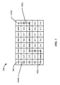
図1は、本開示のいくつかの態様による、温度に基づくルート選択の一例を示す。ルートポイントのグリッド100は、第1のエンドポイント102Aから第2のエンドポイント102Bにワイヤをルーティングするために画定される。各ルートポイントは、ルートポイントのグリッド100内の枠のうちの1つによって表される。したがって、図1の例では、40個のルートポイントが存在する。実際には、所与のルートポイントは、一般に、対応する枠の中央に位置することになる。
FIG. 1 illustrates an example of temperature-based route selection according to some aspects of the present disclosure. A
下でより詳細に論じるように、ルート選択方式は、各ルートポイントに関連する温度特性を決定(たとえば、推定)することを必要とする。これらの温度特性に基づいて、各ルートポイントの温度特性が第1のエンドポイント102Aおよび第2のエンドポイント102Bの温度特性と相関する範囲に関して決定が行われる。図1の例では、所与の枠内の数は、その枠に関する温度相関余因子を表し、ここで、0.99は、近似的な全温度相関を表し、0.0は温度相関の不在を表す。したがって、ルーティングポイントのグリッド100内の第1のルーティングポイント104は、第1のエンドポイント102Aおよび第2のエンドポイント102Bとの0.3の温度相関余因子を有する。異なる実装形態では(たとえば、0未満の値または1を超える値を含めて)異なる相関余因子範囲が使用され得ることを諒解されたい。
As discussed in more detail below, route selection schemes require determining (eg, estimating) the temperature characteristics associated with each route point. Based on these temperature characteristics, a determination is made regarding the extent to which the temperature characteristics of each route point correlate with the temperature characteristics of the
本明細書の教示によれば、第1のエンドポイント102Aと第2のエンドポイント102Bとの間の可能なルートのすべてのうちのどのルートが第1のエンドポイント102Aおよび第2のエンドポイント102Bと最良の温度相関を有するかを決定することによって、第1のエンドポイント102Aと第2のエンドポイント102Bとの間のルートが選択される。図1の例を続けると、最良のルートは、したがって、集合的に最高相関余因子を有するルートになる。したがって、第2の破線106Bによって表されたルートなど、任意の他の予想されるルートに対して、第1の破線106Aによって表されたルートが選択される。
According to the teachings herein, which of all possible routes between the
図1のルーティング方式は、したがって、エンドポイントの対間のルート上に存在する異なる温度条件から生じるタイミングスキュー問題を対象とする。たとえば、プリント回路基板(PCB)、集積回路(IC)、または他の回路内の構成要素の作業負荷差分は予想されるルーティングパスにわたって不均一な温度勾配をもたらし得る。特定の例として、プロセッサの作業負荷が非常に高いとき、IC内など、PCB上のプロセッサ周囲のエリアは、一般に、PCBまたはICの他のエリアよりも熱くなる。ワイヤ抵抗と温度との間の線形関係を仮定すると、高い温度分散(temperature variance)は、たとえば、100%程度までワイヤ上の伝搬遅延を増大させる可能性がある。 The routing scheme of FIG. 1 therefore addresses the timing skew problem that results from the different temperature conditions that exist on the route between the pair of endpoints. For example, workload differentials of components in a printed circuit board (PCB), integrated circuit (IC), or other circuit may result in a non-uniform temperature gradient across the expected routing path. As a specific example, when the processor workload is very high, the area around the processor on the PCB, such as in an IC, is generally hotter than other areas of the PCB or IC. Assuming a linear relationship between wire resistance and temperature, a high temperature variance can increase the propagation delay on the wire, for example, by as much as 100%.
その上、所与のエリア内の温度は経時的に変化し得る。著しい温度勾配が存在する場合、したがって、伝搬遅延、タイミングスキュー(たとえば、クロックスキュー)、およびスキュー変動の点で、システムに不確実性が付与され得る。さらに、PCB、ICなどの上で相互接続がグローバルにルーティングされるとき、これらの温度勾配の遅延およびスキューの影響はなお一層問題になる可能性がある。 Moreover, the temperature in a given area can change over time. If there are significant temperature gradients, therefore, uncertainty can be added to the system in terms of propagation delay, timing skew (eg, clock skew), and skew variation. Furthermore, the effects of these temperature gradient delays and skews can become even more problematic when interconnects are routed globally on PCBs, ICs, and the like.
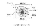
図2および図3は、異なる温度を受けたルーティングエリアの簡略化された例を示す。第1のエリア202Aは、第1のエリア202Aの近傍にある回路の動作の間、T1度の比較的高い温度を受ける。図2および図3の複雑性を低減するために、この回路は示されていない。第2のエリア202Bは、近くの回路の動作の間、T1度よりも低いT2度の温度を受ける。第3のエリア202Cは、近くの回路の動作の間、T2度よりも低いT3度の温度を受ける。
Figures 2 and 3 show simplified examples of routing areas subjected to different temperatures. The
概して、ワイヤの温度とワイヤの抵抗との間に直接的な関係が存在する。したがって、ワイヤに沿った温度差は、ワイヤを通る伝搬遅延に著しい影響を及ぼし得る。図2および図3は、ワイヤが高温のエリアを通過するときに生じ得る伝搬遅延の増大の一例を示す。 In general, there is a direct relationship between wire temperature and wire resistance. Thus, temperature differences along the wire can significantly affect the propagation delay through the wire. 2 and 3 show an example of an increase in propagation delay that can occur when a wire passes through a hot area.
図2では、ソースポイントSにおいて生成された信号は、まず、第1のワイヤセグメント204Aを介して第1のシンクポイントAに伝搬し、第2のワイヤセグメント204Bを介して第2のシンクポイントBに伝搬する。ソースポイントSから第1のシンクポイントAまでの伝搬遅延は1ナノ秒であるのに対して、ソースポイントSから第2のシンクポイントBまでの伝搬遅延は2ナノ秒である。第1のワイヤセグメント204Aも第2のワイヤセグメント204Bも、第1のエリアから第3のエリア202A〜202Cのいずれも通過しないことに留意されたい。
In FIG. 2, the signal generated at the source point S first propagates through the
図3では、第1のワイヤセグメント304Aは第1のエリアから第3のエリア202A〜202Cのいずれも通過しない。しかしながら、第2のワイヤセグメント304Bは、第1のエリアから第3のエリア202A〜202Cの各々を通過する。したがって、図3では、ソースポイントSから第2のシンクポイントBまでの伝搬遅延は4ナノ秒である。したがって、図2および図3は、ワイヤのうちの1つのワイヤためのルートが、ワイヤのうちの別のワイヤとは異なる温度を受けるエリアを通過する場合、異なるワイヤ(たとえば、ディスクリートワイヤまたはツリーの異なる分岐)上で搬送される信号間に著しい温度誘導タイミングスキューが生じ得ることを示す。
In FIG. 3, the
本開示は、いくつかの態様では、温度認識(thermal-aware)ルーティング方式の使用によって、温度誘導タイミングスキューおよびタイミングスキュー変動を最小限に抑えることに関する。有利には、そのような温度認識ルーティング方式は、バッファ挿入技法、架橋挿入技法、および他の従来のスキュー低減技法と対照的に、追加の金属ルーティングなしで、かつ/または電力消費の増大なしで、スキューおよびスキュー変動を効果的に低減する。 The disclosure relates in some aspects to minimizing temperature induced timing skew and timing skew variation through the use of a thermal-aware routing scheme. Advantageously, such temperature-aware routing schemes do not require additional metal routing and / or increase power consumption, in contrast to buffer insertion techniques, bridge insertion techniques, and other conventional skew reduction techniques. Effectively reduce skew and skew fluctuations.
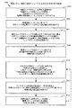
上記を念頭において、本開示による、温度認識ルーティング機能に関する動作の例が、図4のフローチャートに関してより詳細に説明される。便宜上、図4の動作は(または、本明細書で論じ、もしくは教示する他のどの動作も)、特定の構成要素によって実行されるものとして説明され得る。しかしながら、様々な実装形態では、これらの動作は、他のタイプの構成要素によって実行され得、かつ異なる数の構成要素を使用して実行され得ることを諒解されたい。また、本明細書で説明する動作のうちの1つまたは複数は、所与の実装形態において採用され得ないことも諒解されたい。 With the above in mind, an example of operations related to temperature aware routing functionality according to the present disclosure will be described in more detail with respect to the flowchart of FIG. For convenience, the operations of FIG. 4 (or any other operation discussed or taught herein) may be described as being performed by a particular component. However, it should be appreciated that in various implementations, these operations may be performed by other types of components and may be performed using a different number of components. It should also be appreciated that one or more of the operations described herein may not be employed in a given implementation.
図4は、本開示のいくつかの態様による、相関余因子行列に基づいてワイヤをルーティングするためのプロセス400を示す。プロセス400は、回路設計ツールまたは何らかの他の適切な装置内に位置し得る処理回路1810(図18)内で行われ得る。別の態様では、プロセス400は、図17に示す回路設計システム1700によって実装され得る。当然、本開示の範囲内の様々な態様では、プロセス400は、ワイヤルーティング動作をサポートすることができる任意の適切な装置によって実装され得る。
FIG. 4 illustrates a
プロセス400によって達成され得る目的の一例は、最も平滑な温度勾配を有し、可能な限り短いワイヤをやはりもたらす、ワイヤのためのルートを見出すことである。いくつかの態様では、平滑な温度勾配は、温度の急激な変化(たとえば、第1のしきい値レベルを超える温度等級の変化)が何もないか、またはごく少なく、大きな温度限界(たとえば、第1のしきい値レベルよりも大きい第2のしきい値を超える温度等級の差)を有さない温度交配を指す。平滑な温度勾配を実現することによって、さもなければルートに沿って温度差(temperature variations)によって生じ得るスキューおよびスキュー変動を低く保つことができる。加えて、(たとえば、迷路ルーティングを使用することにより)ワイヤの長さを短く保つことによって、ワイヤに関連する電力消費を低く保つことができる。
One example of an objective that can be achieved by
いくつかの実装形態では、温度に関して非常に相関するエンドポイント(たとえばピンペア(pin pairs))間のルートを見出すためにプロセス400が使用される。たとえば、このルーティング方式は、両方のエンドポイントが経時的に同じ温度であるか、またはそれに近い温度である傾向があるシナリオに特に有利であり得る。
In some implementations,
概して、プロセス400は、エンドポイントと最高温度相関を有するルートを見出すことを試みる。したがって、ルート選択プロセスは、非常に相関するエリア上にすべてのルーティング経路を構築することを試みる。そのように非常に相関するエリアを構築することによって、ルートにわたって見られる温度の何らかの変化はより平滑になる(たとえば、何らかの温度変化の等級はより小さくなる)傾向がある。したがって、ルートに関連するタイミングスキューおよびスキュー変動はますます制御され、予測可能になり得る。
In general,
このためにさらに、プロセス400は、いわゆる、ホットスポットを回避することもできる。たとえば、ルート選択プロセスは、選択されたルートが温度限界を受けた(すなわち、熱すぎる、または冷たすぎる)いずれのエリアも通過しないことを確実にし得る。
To this end, the
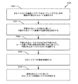
ブロック402で、時間的可変(temporal variant)空間相関行列(マップ)を生成する。ここで、ルーティングエリア(たとえば、PCBまたはIC全体)が、合計でN個のノードを有する均一グリッドに分割される。N個のノードの各々における温度は、次いで、たとえば、ランダムプロセスによってモデル化される。各ノードは、したがって、式1によって示されるN個の時間インスタンスにおいてサンプル化された温度シーケンスによって記述される。
Ln1 = {T(t1,n1),..., T(tp,n1),T(tp+1,n1),..., T(tN,n1)} (1)
Ln2 = {T(t1,n2),..., T(tp,n2),T(tp+1,n2),..., T(tN,n2)}
...
LnN = {T(t1,nN),..., T(tp,nN),T(tp+1,nN),..., T(tN,nN)}
At
L n1 = {T (t 1 , n 1 ), ..., T (t p , n 1 ), T (t p + 1 , n 1 ), ..., T (t N , n 1 )} (1)
L n2 = {T (t 1 , n 2 ), ..., T (t p , n 2 ), T (t p + 1 , n 2 ), ..., T (t N , n 2 )}
...
L nN = {T (t 1 , n N ), ..., T (t p , n N ), T (t p + 1 , n N ), ..., T (t N , n N )}
温度(空間)相関行列は、したがって、式2に示されるように定義され得る。
The temperature (spatial) correlation matrix can thus be defined as shown in

ここで、cov(i,j)は、式3に示されたように、ノード間の共分散行列である。 Here, cov (i, j) is a covariance matrix between nodes as shown in Equation 3.
式1で参照され、式4に示されたパラメータσiおよびσjは、それぞれ、ノードniおよびnjに関する標準偏差である。
Parameters σ i and σ j referred to in
最終的に、それぞれ、ノードniおよびnjに関する平均温度は式5に示される。 Finally, the average temperatures for nodes n i and n j are shown in Equation 5, respectively.
図4のブロック404で、ブロック402で生成された空間相関行列に基づいて、相関余因子行列(マップ)を生成する。本明細書で論じるように、いくつかの態様では、この動作は、指定されたワイヤターゲットポイント(たとえば、エンドポイント)に関してグリッド内の各ポイントの温度相関を決定することを必要とする。
In
ターゲットi,jに対するエリアP(CCp)内の相関余因子は、2つの対応する係数に基づいて(たとえば、それらの係数の積として、またはその和として)定義される。相関余因子が係数の積に基づく場合、CCp = cov(i,p) * cov(p,j)である。ここでも、高い相関余因子値を有するエリアは、両方のルーティングターゲットポイントとの高い相関を表す。 The correlation factor in area P (CCp) for target i, j is defined based on two corresponding coefficients (eg, as the product of these coefficients or as the sum thereof). When the correlation cofactor is based on the product of coefficients, CCp = cov (i, p) * cov (p, j). Again, areas with high correlation factor values represent a high correlation with both routing target points.
ブロック406で、相関余因子行列とルート距離とに基づいて、ワイヤをルーティングされる。いくつかの実装形態では、最も平滑な可能な温度勾配を有する最短のルートを見出す試みにおいて、温度認識ルーティングとともに、迷路ルーティングアルゴリズムなどのルーティングアルゴリズムが使用される。
At
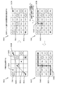
図5は、相関余因子行列に基づくルート選択の一例をグラフィカルな様式で示す。図5は、動作の順番、すなわち、第1の段階500A、第2の段階500B、第3の段階500C、および第4の段階500Dの順番で標示されたルート選択の4つの異なる段階におけるグリッドを示す。
FIG. 5 shows an example of route selection based on the cofactor matrix in a graphical manner. Figure 5 shows the grid in four different stages of route selection, labeled in order of operation, i.e.
この例では、第1の段階500Aは、第1のエンドポイント502Aと第2のエンドポイント502Bとの間の中間点を選択することを必要とする。この目的で、各々が単一の太丸によって表される4つの予想される中間点のセットが識別される。例示のために、第1の中間点504Aおよび第2の中間点504Bが図5において特に標示されている。予想される中間点の各々に関して温度相関余因子が算出され、好ましくは、第1のエンドポイントおよび第2のエンドポイント502Aおよび502Bに対して最高温度相関を有する予想される中間点がルートのための中間点として選択される。この例では、第2の中間点504Bは0.99の相関余因数を有し、したがって、この中間点がルーティング動作のための中間点として選択される。他の予想される中間点の相関余因数は図5の複雑性を低減するために標示されていない。
In this example, the
上記のように、いくつかの実装形態では、ルーティング動作はいわゆるホットスポットを回避する。ホットスポットは、図5に星として表されている。例示のために、これらのホットスポットのうちの第1のホットスポット506が特に標示されている。いくつかのシナリオでは、ホットスポットの存在は、場合によっては、所望される中間点の選択を妨げる可能性があることを諒解されたい。たとえば、ホットスポットは中間点に対する直接ルートを妨害する可能性がある。
As noted above, in some implementations, the routing operation avoids so-called hot spots. Hot spots are represented as stars in Figure 5. For illustration, the first
選択された中間点504Bがそのルートのために選択されると、第2の中間点504Bを通過するルートを識別する必要がある。具体的には、ルート選択は、第1の破線508Aによって概して表される、第2の中間点504Bから第1のエンドポイント502Aまでのルートを識別することを必要とする。加えて、ルート選択は、第2の破線508Bによって概して表される、第2の中間点504Bから第2のエンドポイント502Bまでのルートを識別することを必要とする。
Once the selected
この目的で、ルーティング動作は第2の段階500Bに進み、そこで、各ルーティングポイントに関する相関余因子が算出される。図1に示したように、相関余因子は、0.0からおよそ1.0(たとえば、0.9999)に及び得る。視覚的な助けとして、このルーティングポイントがそのルートのための中間点であることを強調するために、第2の中間点504Bに円が加えられている。
For this purpose, the routing operation proceeds to a
ルーティング動作は、次いで、第3の段階500Cに進み、そこで、第2の中間点504Bと第2のエンドポイント502Bとの間の所望されるルート510Aが識別される。本明細書で論じるように、最高相関余因子値を有するルートがここで選択される。また、このルート選択の間、ホットスポットが回避される。
The routing operation then proceeds to a
最終的に、ルーティング動作は第4の段階500Dに進み、そこで、第2の中間点504Bと第1のエンドポイント502Aとの間の所望されるルート510Bが識別される。ここでも、最高相関余因子値を有するルートが選択される。加えて、ホットスポットが回避される。
Eventually, the routing operation proceeds to a
次に、図6を参照すると、余因子行列の生成および使用についてより詳細に説明される。上述のように、高温度変動(temperature variability)は、ワイヤルートに関連する遅延およびスキューに著しい影響を及ぼし得る。本明細書で教示する温度認識ルーティングは、各ノード間の遅延を評価し、スキューおよびスキュー変動を低減させるために、距離と温度相関の両方を考慮することができる。 Next, the generation and use of the cofactor matrix will be described in more detail with reference to FIG. As mentioned above, temperature variability can significantly affect the delay and skew associated with the wire route. The temperature aware routing taught herein can account for both distance and temperature correlation to evaluate delay between each node and reduce skew and skew variation.
経時的な動的温度差は異なるスキューを生成するため、このルーティング方式は、より安定したスキュー変動を保証することを試みる際に、温度の視点から、最も平滑なルーティング経路を識別する。このルーティング方式は、空間相関および温度相関とともに、時変温度差を考慮する。時変温度マップを解析することによって、温度相関マップが次いで生成される。このようにして、このルーティング方式は、最高相関余因数値を有するルートを識別し、それによって、より良好な熱耐性を有するルートを提供し得る。加えて、温度相関マップによって示された何らかのホットスポットエリアを回避することによって、このルーティング方式は最悪スキューをさらに低減させることができる。 Because dynamic temperature differences over time generate different skews, this routing scheme identifies the smoothest routing path from a temperature perspective when attempting to guarantee a more stable skew variation. This routing scheme takes into account time-varying temperature differences as well as spatial and temperature correlations. A temperature correlation map is then generated by analyzing the time-varying temperature map. In this way, this routing scheme may identify the route with the highest correlation factor value, thereby providing a route with better heat tolerance. In addition, by avoiding any hot spot areas indicated by the temperature correlation map, this routing scheme can further reduce the worst skew.
最初に、回路設計プロセスは、PCB、IC、または何らかの他の適切な構造のエリア602内の回路を位置特定することを必要とする。これは、たとえば、適切なコンピュータ支援設計(CAD)システムを使用して達成され得る。
Initially, the circuit design process entails locating the circuit within
次いで、エリア602に関して空間温度解析604が実行される。いくつかの態様では、これは、ある時間期間にわたってエリア602の異なるポイントにおける温度を決定すること(たとえば、推定すること)を必要とする。たとえば、エリア602内に位置する回路の温度特性に関する情報、およびこれらの回路がどのように動作するように構成されているかに関する情報を有するシミュレーションプログラムは、回路が動作中であるとき、エリア602内の様々なポイントにおいて予想される温度の推定値を生成することができる。
A
エリア602内の回路の近傍にあるそのような時変温度をモデル化するために、PCB、IC、または他のルーティング構造上にグリッドが画定され、各グリッドに温度範囲が割り当てられる。この温度範囲は、測定または温度シミュレーションによって取得され得る。たとえば、これらの回路は、対応する温度プロファイルを取得するために、すべての動作状態を通して実行され得る(たとえば、回路に関する完全な命令セットがテストされ得る)。
To model such time-varying temperatures in the vicinity of the circuitry in
特定の非限定的な例として、温度解析は、マイクロアーキテクチャレベルの電力および温度シミュレーションを必要とし得る。エリア602は、合計でN個のノードを有する均一グリッドに分割される。(各々、時間期間tpを用いて)適切なベンチマークアプリケーションを順番に適用することによって、サイクル精度(ピコ秒の尺度)の動的電力を熱定数尺度(ミリ秒の尺度)で平均化することによって熱出力が取得される。この時変熱出力を入力として使用して、グリッド内の各ノードnjに関して異なる時間インスタンスtjにおいて、エリア602を介した一時的温度T(ti,nj)が算出される。温度差に関する相関を自動的に抽出するために、ランダムプロセスによって、N個のノードにおける温度をモデル化することができる。グリッド内の各ノードは、N個の時間インスタンスにおいてサンプル化された温度シーケンスによって、このようにして説明され得る。図6は、時間インスタンスt1からtNに関する3次元温度行列606をもたらす簡略化された例を示す。非限定的な例では、温度行列606は上に示された式1に対応する。行列606は「3次元行列」と呼ばれるが、これは行列606が値のN個の2Dアレイのセットを含むためであり、この場合、Nはノードの数であることに留意されたい。しかしながら、これは対応する基板が複数のレイヤを有すること、またはノードの3Dグリッドが活用されることを暗示しない。ノードの3Dグリッドが画定および活用されるマルチレイヤ基板の、図26以下の中で提供される詳細な例を参照されたい。
As a specific, non-limiting example, temperature analysis may require microarchitecture level power and temperature simulation.
相関算出608は、相関行列610を生成するための入力として温度行列606を使用する。非限定的な例では、相関算出608は上に示された式2〜5に対応する。そのような場合、相関行列610は、したがって、式2に対応することになる。たとえば、相関係数C(i,j)は事前算出され、表内に記憶され得る。
余因子計算612は、ルートのために指定されたターゲットポイント(たとえばエンドポイント)に関連する余因子行列614を生成するための入力として相関行列610を使用する。高い相関余因子値を有するグリッド内のポイントは、両方のルーティングターゲットポイントとの高い相関を表す。上記のように、いくつかの実装形態では、相関余因子は、2つのターゲットポイントに関連する係数の積に基づく: CCp = cov(i,p) * cov(p,j)。他の実装形態では、相関余因子は係数の和に基づく、CCp = cov(i,p) + cov(p,j)。2つのターゲットポイントを有するポイントの相関を示すのに役立つ他のアルゴリズムも同様に使用され得る。
The
最終的に、温度認識ルーティング616は、最高相関値を有するルート618を識別するための入力として、余因子行列614を使用する。たとえば、温度認識ルーティング616は、2つのターゲットポイント間の各予想されるルートに関する相関値を算出することができる。ルートに関する相関値は、そのルートに沿ったグリッドポイントに関連する個々の余因子値の関数である。たとえば、個々の余因子値は、そのルートに関する相関値を生成するために、一緒に乗算されてよく、一緒に加算されてよく、または何らかの他の方法で演算されてよい。
Finally, temperature awareness routing 616 uses
設計目的に応じて、様々な実装形態で(たとえば、迷路ルーティングなど)様々なタイプのルーティングアルゴリズムを用いることができる。温度認識ルーティングは、マンハッタンルーティング規則または他のルーティング規則を用いることができる。したがって、ルーティングは「上方」ルーティング選定もしくは「右側」ルーティング選定に制限されなくてよく、または画定されたルーティングウィンドウ内に留まるように制限されなくてもよい。したがって、これがルートのために優れたスキュー特性をもたらすシナリオでは、コース反転(たとえば、バックトラッキング)を用いることもできる。 Depending on the design objective, different types of routing algorithms can be used in different implementations (eg, maze routing, etc.). Temperature aware routing can use Manhattan routing rules or other routing rules. Thus, routing may not be limited to “upward” routing selections or “right” routing selections, or may be limited to stay within a defined routing window. Therefore, course inversion (eg, backtracking) can also be used in scenarios where this results in excellent skew characteristics for the route.
2次元または3次元のルーティングに関して、温度ベースのルーティングが使用され得る。たとえば、ルーティングは、PCBの異なるレイヤにわたって、ICの異なるレイヤにわたって、積層ICにわたって、または何らかの他のマルチレイヤ構造にわたって実行され得る。この場合、異なるレイヤ内のすべての予想されるルートポイントに関して温度マップが算出され得、この3次元温度マップに基づいてルーティング判定が行われる。図7および図8は、それぞれ、2つの異なるタイプの基板上のマルチレイヤルーティング(すなわち、3次元ルーティング)の2つの例を示す。追加の例については、図26以下を参照して下でより詳細に説明する。 For two-dimensional or three-dimensional routing, temperature-based routing can be used. For example, routing may be performed across different layers of the PCB, across different layers of IC, across stacked ICs, or over some other multilayer structure. In this case, a temperature map may be calculated for all possible route points in different layers and a routing decision is made based on this three-dimensional temperature map. FIGS. 7 and 8 each show two examples of multilayer routing (ie, three-dimensional routing) on two different types of substrates. Additional examples are described in more detail below with reference to FIG.
図7は、集積回路ダイ基板700上のルーティングの簡略化された例を示す。堆積技法および他の作製技法の使用により、基板700の様々なレイヤ上に回路702および金属ワイヤ(トレース)が形成される。この例では、ワイヤは、第1の金属レイヤ704(たとえば、第1のワイヤルーティングレイヤ)上および第2の金属レイヤ706(たとえば、第2のワイヤルーティングレイヤ)上に形成される。さらに、必要な場合、ワイヤは複数のレイヤ上にルーティングされ得、それによって、適切な位置において、ワイヤはあるレイヤから別のレイヤへの遷移708を含む。
FIG. 7 shows a simplified example of routing on the integrated
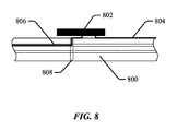
図8は、プリント回路基板の基板800上のルーティングの簡略化された例を示す。堆積技法および他の作成技法の使用により、回路802(この例では、表面実装構成要素)および金属ワイヤ(トレース)が基板800の様々なレイヤ上に形成されるか、またはそれらのレイヤに取り付けられる。この例では、ワイヤは、第1の金属レイヤ804(たとえば、第1のワイヤルーティングレイヤ)上および第2の金属レイヤ806(たとえば、第2のワイヤルーティングレイヤ)上に形成される。さらに、必要な場合、ワイヤは複数のレイヤ上にルーティングされてよく、それによって、いわゆるビア808は、あるレイヤ上のワイヤのあるセクションを別のレイヤのワイヤの別のセクションに電気的に結合する。
FIG. 8 shows a simplified example of routing on a printed
最終的に、ルーティング判定は、物理的要因ならびに温度要因を考慮に入れることができる。たとえば、重み係数をあるレイヤから別のレイヤへの遷移、ビアの使用、コース反転、または他の物理的要因と関連付けることができる。いくつかの態様では、これらの物理的要因は、ルートに関連する信号スキュー、電力消費、または何らかの他の動作パラメータに影響を及ぼし得る。したがって、重み付け係数を使用して、そのような影響を定量化することができる。したがって、(たとえば、最低スキューを有するルート、別のルートのスキューと最も整合するスキューを提供するルート、最低電力消費を有するルートなど)最良のルートの決定は、温度相関とこれらの他の重み係数の平衡に基づき得る。 Finally, the routing decision can take into account physical factors as well as temperature factors. For example, a weighting factor can be associated with a transition from one layer to another, the use of vias, course reversal, or other physical factors. In some aspects, these physical factors may affect signal skew, power consumption, or some other operating parameter associated with the route. Thus, weighting factors can be used to quantify such effects. Thus, the determination of the best route (e.g., the route with the lowest skew, the route that provides the best match with the skew of another route, the route with the lowest power consumption, etc.) depends on the temperature correlation and these other weight factors Based on the equilibrium of
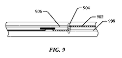
図9は、ルーティング判定がレイヤベースの重み係数を考慮し得るシナリオの一例を示す。特定のルートを使用する判定は、そのルートが単一のレイヤ上にあるか、または複数のレイヤ上にあるかを考慮に入れることができる。具体的には、(たとえば、インピーダンス不連続性により)レイヤ間の遷移はルートの信号伝搬特性に悪影響を及ぼし得るため、ルーティング判定は、一回または複数回、レイヤ間を遷移するルートに不利益をもたらし得る。 FIG. 9 illustrates an example scenario where the routing decision may take into account layer-based weighting factors. The decision to use a particular route can take into account whether the route is on a single layer or on multiple layers. Specifically, routing decisions are detrimental to routes that transit between layers one or more times, because transitions between layers (for example, due to impedance discontinuities) can adversely affect the signal propagation characteristics of the route. Can bring
一例として、ルート902に関する相関値を算出した後、この相関値を調整して、第1のレイヤ906と第2のレイヤ908との間の遷移904を含めて、ルート902を明らかにすることができる。たとえば、ルート902に関連するスキューが遷移904によって悪影響を受けることを示すために、ルート902に関する元の相関値が重み係数だけ低減され得る。
As an example, after calculating the correlation value for
別の例として、ルート902に関する相関値、ならびにルート902に関する1つまたは複数の重み係数に基づいて、ルーティング判定を行うことができる。そのような重み係数は、限定はしないが、ルート902の長さ、およびルート902内のレイヤ間の遷移の数を示し得る。したがって、このルート選択アルゴリズムは、予想されるルートの各々に関する1つまたは複数の重み係数を算出し、これらの重み係数と相関値とを使用して、別のルートに対してあるルートを選択するかどうかを決定することができる。
As another example, a routing decision can be made based on a correlation value for
図10は、ルーティング判定がビアベースの重み係数を考慮し得るシナリオの一例を示す。ここで、特定のルートを使用する判定は、そのルートがビアを通過するかどうかを考慮に入れることができる。ビアの使用は(たとえば、インピーダンス不連続性により)ルートの信号伝搬特性に悪影響を及ぼし得るため、ルーティング判定は、1つまたは複数のビアを使用するルートに不利益をもたらし得る。 FIG. 10 illustrates an example scenario where the routing decision can take into account via-based weighting factors. Here, the decision to use a particular route can take into account whether the route passes through a via. Because the use of vias can adversely affect the signal propagation characteristics of a route (eg, due to impedance discontinuities), routing decisions can be detrimental to routes that use one or more vias.
一例として、ルート1002に関する相関値を算出した後、この相関値を調整して、第1のレイヤ1006と第2のレイヤ1008との間のビア1004を含めて、ルート1002を明らかにすることができる。たとえば、ルート1002に関連するスキューがビア1004によって悪影響を受けることを示すために、ルート1002に関する元の相関値が重み係数だけ低減され得る。
As an example, after calculating the correlation value for the
別の例として、ルート1002に関する相関値、ならびにルート1002に関する1つまたは複数の重み係数に基づいて、ルーティング判定を行うことができる。そのような重み係数は、限定はしないが、ルート1002の長さ、およびルート1002内のビア1004の数を示し得る。したがって、このルート選択アルゴリズムは、予想されるルートの各々に関する1つまたは複数の重み係数を算出し、これらの重み係数と相関値とを使用して、別のルートに対してあるルートを選択するかどうかを決定することができる。
As another example, a routing decision can be made based on a correlation value for
図11は、コース反転ベースの重み係数を考慮し得るシナリオの一例を示す。このシナリオでは、特定のルートを使用する判定は、そのルートがそのコースを反転させるかどうかを考慮に入れることができる。そのようなコース反転は(たとえば、インピーダンス不連続性により、所望されるエリアの外の遷移、またはルートの延長により)ルートの信号伝搬特性に悪影響を及ぼし得るため、ルーティング判定は、1つまたは複数のコース反転を含むルートに不利益をもたらし得る。図11は、より所望されるルートの使用を妨害するホットスポット(たとえば、ホットスポット1104)によって生じるコース反転1102の一例を示す。
FIG. 11 shows an example of a scenario where a course inversion-based weighting factor can be considered. In this scenario, the decision to use a particular route can take into account whether that route reverses the course. Because such course reversal can adversely affect the signal propagation characteristics of the route (e.g., due to impedance discontinuities, transitions outside the desired area, or route extension), the routing decision can be one or more Can be detrimental to routes involving course reversals. FIG. 11 shows an example of
一例として、ルート1106に関する相関値を算出した後、この相関値を調整して、コース反転1102を含めて、ルート1106を明らかにすることができる。たとえば、ルート1106に関連するスキューがコース反転1102によって悪影響を受けることを示すために、ルート1106に関する元の相関値が重み係数だけ低減され得る。
As an example, after calculating the correlation value for the
別の例として、ルート1106に関する相関値、ならびにルート1106に関する1つまたは複数の重み係数に基づいて、ルーティング判定を行うことができる。そのような重み係数は、限定はしないが、ルート1106の長さ、およびルート1106内のコース反転1102の数を示し得る。この場合も、このルート選択アルゴリズムは、予想されるルートの各々に関する1つまたは複数の重み係数を算出し、これらの重み係数と相関値とを使用して、別のルートに対してあるルートを選択するかどうかを決定することができる。
As another example, a routing decision can be made based on a correlation value for
いくつかの実装形態では、複数の積層基板上に3次元マルチレイヤルーティングが用いられる。たとえば、上の図7〜図10で参照された様々なレイヤは、いくつかのシナリオでは、積層基板であり得る。したがって、本明細書で教示するルートの識別は、いくつかの実装形態では、複数の積層基板上のルートを識別することを必要とし得る。追加の3Dの例については、図26以下を参照して下でより詳細に説明する。 In some implementations, 3D multilayer routing is used on multiple stacked substrates. For example, the various layers referenced in FIGS. 7-10 above may be laminated substrates in some scenarios. Accordingly, the identification of routes taught herein may require identifying the routes on multiple stacked substrates in some implementations. Additional 3D examples are described in more detail below with reference to FIG.
本開示は、一態様では、温度要件とルートの長さ要件とを平衡させることによって、ルートを選択することに関する。たとえば、代替のルートがより良好な温度特性を有する場合、代替のルートよりも短いルートは選択され得ない。反対に、代替のルートの長さが代替のルートよりも長い場合、そのルートよりも良好な温度特性を有するルートは選択され得ない。したがって、(たとえば、最低スキューを有するルート、別のルートのスキューと最も整合するスキューを提供するルート、最低電力消費を有するルートなど)最良のルートの決定は、温度相関と距離要因の両方に基づき得る。 The disclosure relates, in one aspect, to selecting a route by balancing temperature requirements and route length requirements. For example, if the alternative route has better temperature characteristics, a shorter route than the alternative route cannot be selected. Conversely, if the length of the alternative route is longer than the alternative route, a route with better temperature characteristics than that route cannot be selected. Therefore, determining the best route (e.g., the route with the lowest skew, the route that provides the best match with the skew of another route, the route with the lowest power consumption, etc.) is based on both temperature correlation and distance factors. obtain.
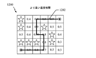
図12および図13は、ルート判定が温度相関とルート距離の両方を考慮し得るシナリオを示す。図12および図13は両方とも、同じ相関行列1200を示すが、それぞれ、異なるルート1202および1302を示す。ルート1202はルート1302よりも高い温度相関を有するが、ルート1302はルート1202よりも短い。
12 and 13 illustrate scenarios where route determination may consider both temperature correlation and route distance. FIGS. 12 and 13 both show the
したがって、ルーティング判定は、どのルートがより良好であるかを決定するために、ルートの長さとルートの温度相関とを考慮に入れることができる。本明細書で論じるように、最良のルートを識別するときに考慮すべき要因は、限定はしないが、スキューの量と、関連するルートとのスキュー整合と、電力消費とを含み得る。 Thus, the routing decision can take into account the length of the route and the temperature correlation of the route to determine which route is better. As discussed herein, factors to consider when identifying the best route may include, but are not limited to, the amount of skew, skew matching with the associated route, and power consumption.
これらの異なる要因がルートごとに比較される様式は、様々な形態をとり得る。一例として、ルーティング方式は、ルート1202および1302に関するこれらの要因間の差分を算出し、これらの差分を(たとえば、重み係数を使用することによって)比較して、ルート1202の改善された温度相関が(たとえば、スキュー、電力消費など)所望される性能の点で、ルート1202のより長い長さをオフセットするかどうかを決定することができる。別の例として、ルーティング方式は、温度相関とルート長さの両方を明らかにする各ルート1202および1302に関する基準を算出することができる。このルーティング方式は、次いで、ルート1202に関する基準をルート1302に関する基準と比較して、最良のルートを識別することができる。
The manner in which these different factors are compared for each route can take a variety of forms. As an example, the routing scheme calculates the difference between these factors for
上記のように、本明細書で教示する温度認識ルーティングは、有利には、関係するワイヤの信号伝搬特性に整合するように使用され得る。これらの例のうち2つについて図14および図15に関して説明する。 As noted above, the temperature-aware routing taught herein can be advantageously used to match the signal propagation characteristics of the wires involved. Two of these examples will be described with respect to FIGS.
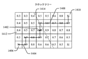
図14は、クロックツリーの分岐のすべてを高い温度相関経路上に配置するようにルーティングされたクロックツリーの一例を示す。クロックソース(図示せず)からのクロック信号は分岐点1402に結合される。クロックツリーの第1の分岐1404は、分岐点1402から第1のシンクポイント1406にルーティングされる。クロックツリーの第2の分岐1408は、分岐点1402から第2のシンクポイント1410にルーティングされる。示すように、第1の分岐および第2の分岐1404および1408のためのそれぞれのルートは、第1のシンクポイントおよび第2のシンクポイント1406および1410と高い温度相関を有するように選択される。
FIG. 14 shows an example of a clock tree that is routed to place all of the branches of the clock tree on a high temperature correlation path. A clock signal from a clock source (not shown) is coupled to
本明細書の議論は2つのターゲットポイントとの温度相関を指す場合が多いが、異なる数のターゲットポイントとの相関に基づいて経路を選択することができる。たとえば、クロックツリーは、3つ以上のシンクポイント(たとえば、図14のポイント1406、1410、および1412)を有し得る。そのような場合、本明細書で説明する技法を用いて、3つ以上のターゲットポイント(たとえば、シンクポイント)に関するルートに沿って最良の温度相関を提供する多分岐(multi-branch)ルートを識別することによって、クロックツリーの複数の分岐のためのルートを識別することができる。 While the discussion herein often refers to temperature correlation between two target points, a path can be selected based on correlation with a different number of target points. For example, the clock tree may have more than two sync points (eg, points 1406, 1410, and 1412 in FIG. 14). In such cases, the techniques described herein are used to identify a multi-branch route that provides the best temperature correlation along the route for three or more target points (e.g., sink points). By doing so, routes for multiple branches of the clock tree can be identified.
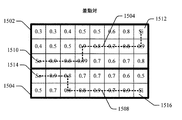
図15は、差動対の両方のレールをより高い温度相関経路に配置するようにルーティングされた差動対の一例を示す。この例では、差動対の第1のレール1504をルーティングするために、(上部の3つの行を含む)第1のグリッド1502が定義され、差動対の第2のレール1508をルーティングするために、(下部の2つの行を含む)第2のグリッド1506が定義される。
FIG. 15 shows an example of a differential pair routed to place both rails of the differential pair in a higher temperature correlation path. In this example, to route the
第1のレール1504は、第1のソースポイント1510において発生し、第1のシンクポイント1512においてシンクする。第2のレール1508は、第2のソースポイント1514において発生し、第2のシンクポイント1516においてシンクする。示すように、第1のレールおよび第2のレール1504および1508のためのそれぞれのルートは、各々、対応するシンクポイントおよびソースポイントと高い温度相関を有するように選択される。
The
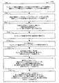
図16は、図14および図15のワイヤをルーティングするために使用され得る迷路ルーティングプロセス1600の一例を示す。プロセス1600は、回路設計ツールまたは何らかの他の適切な装置内に位置し得る処理回路1810(図18)内で行われ得る。別の態様では、プロセス1600は、図17に示す回路設計システム1700によって実装され得る。当然、本開示の範囲内の様々な態様では、プロセス1600は、ワイヤルーティング動作をサポートすることができる任意の適切な装置によって実装され得る。
FIG. 16 shows an example of a
ブロック1602で、時間的可変空間相関行列(マップ)を決定する。たとえば、装置は、その行列を生成することができるか、または別の装置からのその行列を受信することができる。
At
ブロック1604で、クロックツリーが合成されているかどうかに関する決定が行われる。されていない(たとえば、クロックツリールーティングの代わりに、詳細なルーティングが実行される)場合、動作フローはブロック1608に進む。
At
クロックツリーが合成されている場合、動作フローはブロック1606に進み、そこで、クロックツリーに関するマージポイントが指定される。具体的には、マージポイントは最大相関重みを有し、ホットスポットではないマージライン内のポイントに位置する。いくつかの実装形態では、ターゲットポイント間のマンハッタン距離を算出することによってマージラインが識別される。図14は、第1のシンクポイントおよび第2のシンクポイント1406および1410から等距離のマージライン1414の一例を示す。マージライン1414はグリッド内の予想されるマージングポイントと交差する。したがって、ブロック1606の動作は、予想されるマージポイントの各々に関する相関余因子を決定するステップと、予想されるマージングポイントがホットスポットでないことを条件に、最高相関重みを有するマージングポイントを選択するステップとを必要とし得る。
If the clock tree has been synthesized, the operational flow proceeds to block 1606 where a merge point for the clock tree is specified. Specifically, the merge point has a maximum correlation weight and is located at a point in the merge line that is not a hot spot. In some implementations, mergelines are identified by calculating the Manhattan distance between target points. FIG. 14 shows an example of a
ブロック1608で、最高相関余因子重みを有するルートを識別するために、迷路ルーティングが起動され、この場合、ルートはマンハッタン距離によって制約される。
At
図17は、本開示の1つまたは複数の態様がアプリケーションを見出し得る回路設計システム1700の一例を示す。システム1700は、ユーザディスプレイデバイス1704とユーザ入力デバイス1706とに通信可能に結合されたコンピュータ1702(たとえば、ワークステーション)を含む。コンピュータ1702はまた、コンピュータ1702によって生成された設計データがPCB、ICなどを製造する作製システム1710に転送されることを可能にするために、ネットワーク1708に通信可能に結合される。
FIG. 17 illustrates an example
コンピュータ1702は、プロセッサ1712とメモリ1714とを含む。プロセッサ1712は、中央処理ユニット(CPU)、コプロセッサ、演算処理装置、グラフィックス処理ユニット(GPU)、デジタル信号プロセッサ(DSP)などの、任意の適切なタイプの処理ユニットであってよい。メモリ1714は、RAM、ROM、FLASH、ディスクドライブなどの、任意の適切なタイプのメモリ技術を含み得る。
The
メモリ1714内に記憶され、かつ/またはプロセッサ1712によって実装されるルーティングプログラム1716およびシミュレーションモデル1718は、ユーザが本明細書の教示に従って回路設計を生成することを可能にする。たとえば、ユーザは、ディスプレイデバイス1704とユーザ入力デバイスとを使用して、本明細書で教示されるように、(たとえば、ICまたはPCBの)少なくとも1つの基板上に回路を配置し、その少なくとも1つの基板上の様々な位置において温度特性を経時的にシミュレートし、相関行列を生成し、余因子行列を生成し、最良の温度相関を有するルートを選択することができる。ユーザは、次いで、所望される回路構成要素を作り出すためのルート設計1720を作製システム1710に送ることができる。
次に、図18を参照すると、本開示の少なくとも1つの例による、図17のコンピュータ1702などの、装置1800の選択構成要素を示すブロック図である。装置1800(たとえば、設計ツール)は、外部バスインターフェース1802と、記憶媒体1804と、ユーザインターフェース1806と、メモリデバイス1808と、処理回路1810とを含む。処理回路は、外部バスインターフェース1802、記憶媒体1804、ユーザインターフェース1806、およびメモリデバイス1808の各々と電気的に通信するように結合または配置される。
Referring now to FIG. 18, a block diagram illustrating selected components of an
外部バスインターフェース1802は、外部バス1812に対するインターフェースを装置1800の構成要素に提供する。外部バスインターフェース1802は、たとえば、信号駆動回路、信号受信機回路、増幅器、信号フィルタ、信号バッファ、またはシグナリングバスもしくは他のタイプのシグナリング媒体とインターフェースするために使用される他の回路のうちの1つもしくは複数を含み得る。
External bus interface 1802 provides an interface to
処理回路1810は、データを取得、処理、および/または送り、データのアクセスおよび記憶を制御し、コマンドを発行し、他の所望の動作を制御するように構成される。処理回路1810は、少なくとも1つの例において、適切な媒体によって提供される所望のプログラミングを実装するように適合された回路を含み得る。場合によっては、処理回路1810は、プログラミングを実装することによって、またはプログラミングを実装することなく、所望の機能を実行するように適合された回路を含み得る。例として、処理回路1810は、1つもしくは複数のプロセッサ、1つもしくは複数のコントローラ、および/または実行可能なプログラミングを実行するように、かつ/あるいは望の機能を実行するように構成されたその他の構造として実装されてもよい。処理回路1810の例は、汎用プロセッサ、デジタル信号プロセッサ(DSP)、特定用途向け集積回路(ASIC)、フィールドプログラマブルゲートアレイ(FPGA)もしくは他のプログラマブル論理構成要素、個別ゲートもしくはトランジスタ論理、個別ハードウェア構成要素、または本明細書で説明する機能を実行するように設計されたそれらの任意の組合せを含み得る。汎用プロセッサは、マイクロプロセッサ、ならびに任意の通常のプロセッサ、コントローラ、マイクロコントローラ、またはステートマシンを含み得る。処理回路1810はまた、DSPとマイクロプロセッサとの組合せ、いくつかのマイクロプロセッサ、DSPコアと連携する1つもしくは複数のマイクロプロセッサ、ASICとマイクロプロセッサ、または任意のその他のいくつかの様々な構成などのコンピューティング構成要素の組合せとして実装されてもよい。処理回路1810のこれらの例は説明のためであり、本開示の範囲内の他の好適な構成も企図される。
The
処理回路1810は、記憶媒体1804上に記憶されてもよいプログラミングの実行を含めて処理するように適合される。本明細書で使用される「プログラミング」または「命令」という用語は、ソフトウェアと呼ばれるか、ファームウェアと呼ばれるか、ミドルウェアと呼ばれるか、マイクロコードと呼ばれるか、ハードウェア記述言語と呼ばれるか、またはそれ以外で呼ばれるかにかかわらず、限定はしないが、命令セット、命令、コード、コードセグメント、プログラムコード、プログラム、プログラミング、サブプログラム、ソフトウェアモジュール、アプリケーション、ソフトウェアアプリケーション、ソフトウェアパッケージ、ルーチン、サブルーチン、オブジェクト、実行ファイル、実行のスレッド、手順、関数などを含むように広く解釈されなければならない。
The
場合によっては、処理回路1810は、予想されるルートを識別するためのモジュール1814、予想されるルートの温度特性を決定するためのモジュール1816、予想されるルートのうちの1つを選択するためのモジュール1818、選択されたルートの表示を記憶するためのモジュール1820、ポイントのグリッドを識別するためのモジュール1822、電子回路の温度特性を決定するためのモジュール1824、予想されるルートの距離を決定するためのモジュール1826、または分岐点を選択するためのモジュール1828のうちの1つもしくは複数を含み得る。
In some cases, the
予想されるルートを識別するためのモジュール1814は、ルーティングエリア内の2つ以上のターゲットポイントに関する情報を収集し、ターゲットポイント間のルーティングエリア内を横断し得る異なるルートを算出し、予想されるルートの表示を生成するように適合された回路および/またはプログラミング(たとえば、記憶媒体1804上に記憶された、予想されるルートを識別するためのモジュール1830)を含み得る。
A
予想されるルートの温度特性を決定するためのモジュール1816は、予想されるルートに関する情報を獲得し、各予想されるルートに沿った様々なポイントの温度特性を算出し、温度特性の表示を生成するように適合された回路および/またはプログラミング(たとえば、記憶媒体1804上に記憶された、予想されるルートの温度特性を決定するためのモジュール1832)を含み得る。
予想されるルートのうちの1つを選択するためのモジュール1818は、予想されるルートの温度特性に関する情報を獲得し、異なる温度特性の中から最良の温度特性を識別し、その最良の温度特性に関連するルートに関する情報を生成するように適合された回路および/またはプログラミング(たとえば、記憶媒体1804上に記憶された、予想されるルートのうちの1つを選択するためのモジュール1834)を含み得る。
A
選択されたルートの表示を記憶するためのモジュール1820は、選択されたルートに関する情報を獲得し、選択されたルートを示す表示を生成し、その表示を含む信号を生成し、その信号をメモリデバイスに送るように適合された回路および/またはプログラミング(たとえば、記憶媒体1804上に記憶された、選択されたルートの表示を記憶するためのモジュール1836)を含み得る。
A
ポイントのグリッドを識別するためのモジュール1822は、1つもしくは複数の回路のためのルーティングエリアに関する情報を獲得し、そのエリア内のポイントのグリッドを画定し、ポイントの画定されたグリッドの表示を生成するように適合された回路および/またはプログラミング(たとえば、記憶媒体1804上に記憶された、ポイントのグリッドを識別するためのモジュール1838)を含み得る。
電子回路の温度特性を決定するためのモジュール1824は、電子回路に関する情報を獲得し、1つもしくは複数の動作条件の下で電子回路の温度特性を決定し、温度特性の表示を生成するように適合された回路および/またはプログラミング(たとえば、記憶媒体1804上に記憶された、電子回路の温度特性を決定するためのモジュール1840)を含み得る。
予想されるルートの距離を決定するためのモジュール1826は、予想されるルートに関する情報を獲得し、予想されるルートの距離を算出し、予想されるルートの距離の表示を生成するように適合された回路および/またはプログラミング(たとえば、記憶媒体1804上に記憶された、予想されるルートの距離を決定するためのモジュール1842)を含み得る。
分岐点を選択するためのモジュール1828は、ターゲットポイントに関する情報を獲得し、ターゲットポイント間の予想される分岐点を識別し、予想される分岐点のうちの1つを選択し、選択された分岐点を識別する表示を生成するように適合された回路および/またはプログラミング(たとえば、記憶媒体1804上に記憶された、分岐点を選択するためのモジュール1844)を含み得る。
A module for selecting a
記憶媒体1804は、プログラミング、電子データ、データベース、またはその他のデジタル情報を記憶するための、1つもしくは複数のプロセッサ可読デバイスを表す場合がある。記憶媒体1804は、プログラミングを実行するときに処理回路1810によって操作されるデータを記憶するために使用されてもよい。記憶媒体1804は、可搬型または固定式記憶デバイスと、光記憶デバイスと、プログラミングの記憶、収容、および/または搬送が可能な様々なその他の媒体とを含む、処理回路1810によってアクセスすることが可能な任意の利用可能な媒体であってもよい。限定ではなく例として、記憶媒体1804は、磁気記憶デバイス(たとえば、ハードディスク、フロッピーディスク、磁気ストライプ)、光記憶媒体(たとえば、コンパクトディスク(CD)、デジタルバーサタイルディスク(DVD))、スマートカード、フラッシュメモリデバイス(たとえば、カード、スティック、キードライブ)、ランダムアクセスメモリ(RAM)、読出し専用メモリ(ROM)、プログラマブルROM(PROM)、消去可能PROM(EPROM)、電気的消去可能PROM(EEPROM)、レジスタ、取外し可能なディスク、および/またはプログラミングを記憶するためのその他の媒体、ならびにそれらの任意の組合せなどのプロセッサ可読記憶媒体を含み得る。したがって、いくつかの実装形態では、記憶媒体は、非一時的(たとえば、有形の)記憶媒体であってよい。
記憶媒体1804は、処理回路1810が記憶媒体1804から情報を読み取り、その記憶媒体に情報を書き込むことができるように処理回路1810に結合されてもよい。すなわち、記憶媒体1804が少なくとも処理回路1810によってアクセス可能であるように、記憶媒体1804は、処理回路1810に結合されてよく、記憶媒体1804が処理回路1810と一体である例、および/または記憶媒体1804が処理回路1810と分離している例を含む。
記憶媒体1804によって記憶されているプログラミングは、処理回路1810によって実行されると、処理回路1810に、本明細書で説明する様々な機能および/または処理ステップのうちの1つもしくは複数を実行させる。たとえば、記憶媒体1804は、予想されるルートを識別するためのモジュール1830、予想されるルートの温度特性を決定するためのモジュール1832、予想されるルートのうちの1つを選択するためのモジュール1834、選択されたルートの表示を記憶するためのモジュール1836、ポイントのグリッドを識別するためのモジュール1838、電子回路の温度特性を決定するためのモジュール1840、予想されるルートの距離を決定するためのモジュール1842、または分岐点を選択するためのモジュール1844のうちの1つもしくは複数を含み得る。したがって、本開示の1つまたは複数の態様によれば、処理回路1810は、本明細書で説明する装置のいずれかもしくはすべてのためのプロセス、関数、ステップ、および/またはルーチンのうちのいずれかあるいはすべてを(記憶媒体1804と連携して)実行するように適合される。処理回路1810に関係して本明細書で使用する「適合される」という用語は、処理回路1810が、(記憶媒体1804と連携して)本明細書で説明する様々な特徴による特定のプロセス、機能、ステップおよび/またはルーチンを実行するように構成されること、用いられること、実装されること、ならびに/あるいはプログラムされることのうちの1つもしくは複数を行うことを指す場合がある。
The programming stored by the
メモリデバイス1808は、1つまたは複数のメモリデバイスを表すことができ、上に記載したメモリ技術のうちのいずれかまたは任意の他の適切なメモリ技術を含み得る。メモリデバイス1808は、限定はしないが、装置1800の構成要素のうちの1つまたは複数によって使用される他の情報とともに、選択されたルートの表示などの回路設計情報を記憶することができる。メモリデバイス1808はまた、処理回路1810または装置1800の何らかの他の構成要素によって操作されるデータを記憶するために使用され得る。いくつかの実装形態では、メモリデバイス1808および記憶媒体1804は、共通のメモリ構成要素として実装される。
ユーザインターフェース1806は、ユーザが装置1800と相互作用するのを可能にする機能を含む。たとえば、ユーザインターフェース1806は、1つまたは複数のユーザ出力デバイス(たとえば、ディスプレイデバイスなど)および1つまたは複数のユーザ入力デバイス(たとえば、キーボード、接触入力デバイスなど)とインターフェースすることができる。
図19は、本開示のいくつかの態様による、ワイヤルーティングのためのプロセス1900を示す。プロセス1900は、回路設計ツールまたは何らかの他の適切な装置内に位置し得る処理回路1810(図18)内で行われ得る。別の態様では、プロセス1900は、図17に示す回路設計システム1700によって実装され得る。当然、本開示の範囲内の様々な態様では、プロセス1900は、ワイヤルーティング動作をサポートすることができる任意の適切な装置によって実装され得る。
FIG. 19 illustrates a
ブロック1902で、少なくとも1つの基板上でワイヤをルーティングするための予想されるルートを識別する。たとえば、少なくとも1つの基板上で画定されたポイントのグリッド内の第1のエンドポイントと第2のエンドポイントとの間のワイヤのための異なるルートを識別することができる。少なくとも1つの基板は、プリント回路基板の基板、集積回路ダイ基板、または何らかの他のタイプの基板を含み得る。
At
ブロック1904で、ブロック1902で識別された予想されるルートの各々に関して、予想されるルートに関連する温度特性を決定する。たとえば、ブロック1904の動作は、対応する予想されるルートに沿ったポイントのセットの各ポイントに関して、そのポイントとワイヤのルーティングに関連する第1のエンドポイントおよび第2のエンドポイントとの間の温度相関を決定するステップを必要とし得る。
At
いくつかの態様では、予想されるルートに関連する温度特性の決定は、ポイントのグリッドのポイントの各々に関して、そのポイントの温度特性を決定するステップと、それらのポイントの温度特性に基づいて、ポイントのグリッドに対応する空間相関行列を生成するステップと、空間相関行列に基づいて、相関余因子行列を生成すステップであって、相関余因子行列が、ポイントのグリッドのポイントの各々に関して、そのポイントの温度特性を、ワイヤのルーティングに関連する第1のエンドポイントおよび第2のエンドポイントの温度特性と相関させる、生成するステップと、各予想されるルートに関して、相関余因子行列に基づいて、予想されるルートと第1のエンドポイントおよび第2のエンドポイントとの間の温度相関を決定するステップとを必要とし得る。 In some aspects, determining the temperature characteristic associated with the expected route includes determining, for each point of the grid of points, the temperature characteristic of the point and the point based on the temperature characteristic of the point. Generating a spatial correlation matrix corresponding to a grid of, and generating a correlation cofactor matrix based on the spatial correlation matrix, the correlation cofactor matrix for each point of the grid of points Generating a correlation between the temperature characteristics of the first and second endpoints associated with the routing of the wire, and for each expected route based on a cofactor matrix A step that determines the temperature correlation between the route being routed and the first and second endpoints. You may need
ブロック1906で、ブロック1904で決定された温度特性に基づいて、予想されるルートのうちの1つを選択する。いくつかの態様では、ルートの選択は、どの予想されるルートがワイヤのルーティングに関連する第1のエンドポイントおよび第2のエンドポイントとの最高温度相関を有するかを決定するステップを含む。いくつかの態様では、ルートの選択は、異なる予想されるルートに関連するポイントの複数の異なるセットのポイントのうちどのポイントのセットがワイヤのルーティングに関連する第1のエンドポイントおよび第2のエンドポイントとの最高集合温度相関を有するかを決定するステップを含む。いくつかの態様では、ルートの選択は、しきい温度を超える温度に関連する少なくとも1つの基板のエリアを通過する、予想されるルートのうちのいずれも拒否するステップを含む。いくつかの態様では、ルートの選択は、しきい温度を下回る温度に関連する少なくとも1つの基板のエリアを通過する予想されるルートのうちのいずれも拒否するステップを含む。
At
ブロック1908で、選択されたルートの表示をメモリデバイス内に記憶する。たとえば、この表示は、他のルーティングデータおよび回路設計に関連する他の回路データとともに記憶され得る。
At
図20は、複数の予想されるルートの中から最も平滑な温度勾配に関連して選択されたルートに沿ってその上にワイヤを形成させた少なくとも1つの基板を作成するためのプロセス2000を示す。プロセス2000の1つまたは複数の動作は、回路設計ツールまたは何らかの他の適切な装置内に位置し得る処理回路1810(図18)内で行われ得る。別の態様では、処理2000の1つまたは複数の動作は、図17に示した回路設計システム1700によって実装され得る。当然、本開示の範囲内の様々な態様では、プロセス2000は、ワイヤルーティング動作をサポートすることができる任意の適切な装置によって実装され得る。
FIG. 20 shows a
ブロック2002で、少なくとも1つの基板上でワイヤをルーティングするための予想されるルートを識別する。いくつかの態様では、ブロック2002の動作は、ブロック1902の動作に対応し得る。また、上で論じたように、少なくとも1つの基板は、プリント回路基板の基板、集積回路ダイ基板、または何らかの他のタイプの基板を含み得る。
At
ブロック2004で、ブロック2002で識別された予想されるルートの各々に関して、予想されるルートに関連する温度勾配を決定する。いくつかの態様では、温度勾配の決定は、対応する予想されるルートに沿ったポイントのセットの各ポイントに関して、そのポイントとワイヤのルーティングに関連する第1のエンドポイントおよび第2のエンドポイントとの温度相関を決定するステップを含み得る。
At
いくつかの態様では、温度勾配の決定は、ポイントのグリッドのポイントの各々に関して、そのポイントの温度特性を決定するステップと、それらのポイントの温度特性に基づいて、ポイントのグリッドに対応する空間相関行列を生成するステップと、空間相関行列に基づいて、相関余因子行列を生成すステップであって、相関余因子行列が、ポイントのグリッドのポイントの各々に関して、そのポイントの温度特性を、ワイヤのルーティングに関連する第1のエンドポイントおよび第2のエンドポイントの温度特性と相関させる、生成するステップと、各予想されるルートに関して、相関余因子行列に基づいて、予想されるルートと第1のエンドポイントおよび第2のエンドポイントとの間の温度相関を決定するステップとを必要とし得る。 In some aspects, determining the temperature gradient includes, for each point of the grid of points, determining a temperature characteristic of the point and a spatial correlation corresponding to the grid of points based on the temperature characteristic of the point. Generating a correlation cofactor matrix based on the spatial correlation matrix, wherein the correlation cofactor matrix, for each point in the grid of points, represents the temperature characteristics of the point, Correlating with the temperature characteristics of the first and second endpoints associated with the routing, and for each expected route, for each expected route, the expected route and the first Determining a temperature correlation between the endpoint and the second endpoint.
ブロック2006で、予想されるルートのうちのどれが予想されるルートの最も平滑な温度勾配を有するかに基づいて、予想されるルートのうちの1つを選択する。いくつかの態様では、予想されるルートのうちの1つの選択は、どの予想されるルートがワイヤのルーティングに関連する第1のエンドポイントおよび第2のエンドポイントとの最高温度相関を有するかを決定するステップを含み得る。いくつかの態様では、予想されるルートのうちの1つの選択は、ポイントのどのセットがワイヤのルーティングに関連する第1のエンドポイントおよび第2のエンドポイントとの最高集合温度相関を有するかを決定するステップを含み得る。いくつかの態様では、予想されるルートのうちの1つの選択は、しきい温度を超える温度に関連する少なくとも1つの基板のエリアを通過する、予想されるルートのうちのいずれも拒否するステップを含み得る。いくつかの態様では、予想されるルートのうちの1つの選択は、しきい温度を下回る温度に関連する少なくとも1つの基板のエリアを通過する、予想されるルートのうちのいずれも拒否するステップを含み得る。
At
いくつかの態様では、最も平滑な温度勾配は、選択されたルートに沿った第1のエンドポイントおよび第2のエンドポイントとの最高温度相関に対応し得る。いくつかの態様では、最も平滑な温度勾配は、選択されたルートに沿った温度特性の最高適合性に対応し得る。 In some aspects, the smoothest temperature gradient may correspond to the highest temperature correlation with the first endpoint and the second endpoint along the selected route. In some aspects, the smoothest temperature gradient may correspond to the best fit of the temperature characteristic along the selected route.
ブロック2008で、適切な製造動作は少なくとも1つの基板を提供(たとえば、形成または獲得)する。たとえば、作製システムは、集積回路ダイ用の少なくとも1つの基板を形成するか、またはプリント回路基板用の少なくとも1つの基板を形成し得る。
At
ブロック2010で、適切な製造動作は、選択されたルートに従って、少なくとも1つの基板上にワイヤを形成する。たとえば、選択されたルートの経路を示す回路設計データに基づいて、作製システムは、集積回路ダイ用の少なくとも1つの基板上に、またはプリント回路基板用の少なくとも1つの基板上にワイヤを形成し得る。
At
いくつかの態様では、選択されたルートは、しきい温度を超える温度に関連する少なくとも1つの基板の任意のエリアを横断しない。いくつかの態様では、選択されたルートは、しきい温度を下回る温度に関連する少なくとも1つの基板の任意のエリアを横断しない。 In some embodiments, the selected route does not traverse any area of the at least one substrate that is associated with a temperature that exceeds the threshold temperature. In some embodiments, the selected route does not cross any area of the at least one substrate associated with a temperature below the threshold temperature.
いくつかの態様では、選択されたルートは、第1のエンドポイントと、第2のエンドポイントと、分岐点とを含むことが可能であり、それによって、分岐点は第1のエンドポイントと第1のエンドポイントとの間に位置する複数の予想される分岐点の中からの第1のエンドポイントおよび第1のエンドポイントとの最高温度相関と関連付けられる。 In some aspects, the selected route can include a first endpoint, a second endpoint, and a branch point, whereby the branch point is the first endpoint and the second endpoint. Associated with a first temperature endpoint and a maximum temperature correlation with the first endpoint among a plurality of possible branch points located between the first endpoint.
いくつかの態様では、少なくとも1つの基板は、複数のルーティングレイヤ(たとえば、積層基板)を画定し得る。この場合、最も平滑な温度勾配は、複数のルーティングレイヤのうちの少なくとも2つを横断する、予想されるルートのうちの1つと関連付けられ得る。また、最も平滑は温度勾配は、複数のルーティングレイヤのうちの少なくとも2つの間でビアを横断する、予想されるルートのうちの1つと関連付けられ得る。さらに、最も平滑な温度勾配は、コースを反転する、予想されるルートのうちの1つと関連付けられ得る。 In some aspects, the at least one substrate may define a plurality of routing layers (eg, stacked substrates). In this case, the smoothest temperature gradient may be associated with one of the expected routes that traverses at least two of the plurality of routing layers. Also, the smoothest temperature gradient can be associated with one of the expected routes that traverses the via between at least two of the plurality of routing layers. Furthermore, the smoothest temperature gradient can be associated with one of the expected routes that reverses the course.
図21は、本開示のいくつかの態様による、ワイヤルーティング方法の追加の態様を含むプロセス2100を示す。プロセス2100は、回路設計ツールまたは何らかの他の適切な装置内に位置し得る処理回路1810(図18)内で行われ得る。別の態様では、プロセス2100は、図17に示した回路設計システム1700によって実装され得る。当然、本開示の範囲内の様々な態様では、プロセス2100は、ワイヤルーティング動作をサポートすることができる任意の適切な装置によって実装され得る。
FIG. 21 illustrates a
オプションのブロック2102で、基板(たとえば、シングルレイヤ基板またはマルチレイヤ基板)上でワイヤをルーティングするためのエリアを示す少なくとも1つの信号を受信することができる。たとえば、装置の受信機(たとえば、バスインターフェース内の受信機回路または処理回路)は、ワイヤをルーティングするためのエリアを示す情報を含む(たとえば、メッセージを含む)信号を別の装置(たとえば、メモリデバイスまたは送信機回路)から受信することができる。
In
オプションのブロック2104で、基板上のポイントのグリッドを識別することができる。たとえば、グリッドは指定されたルーティングエリア内で画定され得る。
In an
オプションのブロック2106で、ポイントのグリッドの近傍に位置することになる少なくとも1つの電子回路の少なくとも1つの温度特性を決定することができる。たとえば、電子回路の動作の間に、電子回路の近傍において期待される温度を決定するために、シミュレーションを行うことができるか、または測定を行うことができる。この場合、(たとえば、ブロック2120での)ポイントの温度特性の決定は、少なくとも1つの電子回路の少なくとも1つの温度特性に基づき得る。
In an
ブロック2108で、分岐点を選択することができる。たとえば、クロックツリーがルーティングされている場合、どの予想される分岐点が第1のエンドポイントおよび第2のエンドポイントとの最高温度相関を有するかに基づいて、第1のエンドポイントと第2のエンドポイントとの間の複数の予想される分岐点のうちの1つの分岐点を選択することができる。
At
ブロック2110で、予想されるルートを識別する。いくつかの態様では、ブロック2110の動作は、上で論じた、ブロック1902の動作に対応し得る。
At
オプションのブロック2112で、複数のルーティングレイヤのうちの少なくとも2つを横断する、少なくとも1つの予想されるルートを識別することができる。この場合、ルートの選択(たとえば、ブロック2122)は、複数のルーティングレイヤのうちの少なくとも2つを横断する各予想されるルートに重み係数を適用するステップを必要とし得る。
In
オプションのブロック2114で、複数のルーティングレイヤのうちの少なくとも2つの間を、ビアを介して横断する少なくとも1つの予想されるルートを識別することができる。この場合、ルートの選択は、複数のルーティングレイヤのうちの少なくとも2つの間を、ビアを横断する各予想されるルートに重み係数を適用するステップを必要とし得る。
In
オプションのブロック2116で、コースを反転する、少なくとも1つの予想されるルートを識別することができる。この場合、ルートの選択は、コースを反転する各予想されるルートに重み係数を適用するステップを必要とし得る。
In
オプションのブロック2118で、予想されるルートの各々に関して、予想されるルートに関連する距離を識別することができる。この場合、ルートの選択は、予想されるルートに関連する距離に基づき得る。
In
ブロック2120で、識別された予想されるルートの各々に関して、予想されるルートに関連する温度特性を決定する。いくつかの態様では、ブロック2120の動作は、上で論じた、ブロック1904の動作に対応し得る。
At
ブロック2122で、ブロック2120において決定された温度特性に基づいて、予想されるルートのうちの1つを選択する。いくつかの態様では、ブロック2122の動作は、上で論じた、ブロック1906の動作に対応し得る。
At
上記に鑑みて、本明細書の教示に従って実践されるルーティング方式は、有利には、従来のルーティング方式と比べてより効果的なルーティングを実現し得る。たとえば、米国特許第7,155,686号および第8,209,651号は、ワイヤが過剰な熱を生成する場合、ワイヤが移動される、かなり異なる方式を対象とする。また、米国特許第6,775,710号および第7,725,861号はルーティングのコンテキストで「温度」および「ホットスポット」という用語を使用するが、これらの特許は、実際に温度に基づいて何のルーティングも実行しない。 In view of the above, a routing scheme practiced in accordance with the teachings herein can advantageously achieve more effective routing than conventional routing schemes. For example, U.S. Pat. Nos. 7,155,686 and 8,209,651 are directed to a rather different manner in which the wire is moved if it generates excessive heat. US Pat. Nos. 6,775,710 and 7,725,861 also use the terms “temperature” and “hot spot” in the context of routing, but these patents do not actually perform any routing based on temperature.
2D配線実装形態に適用可能な追加の例示的な特徴
図22〜図24を参照すると、次に2D配線実装形態に適用可能である追加のまたは代替の特徴を説明する。これらの特徴のうちの少なくともいくつかは、上で説明した手順を活用するか、または組み込んでいる。簡潔のために、これらの手順は、いずれかの差異を強調する以外、再度詳細に説明されない。
Additional Exemplary Features Applicable to 2D Wiring Implementations Referring to FIGS. 22-24, additional or alternative features that are applicable to 2D wiring implementations will now be described. At least some of these features utilize or incorporate the procedures described above. For the sake of brevity, these procedures will not be described in detail again, except to highlight any differences.
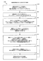
図22は、ルーティングが、最悪スキュー推定を考慮に入れ、動的探索ウィンドウを活用する、適切に装備されたルーティングシステムによって実行され得る例示的な2Dルーティング手順2200を示す。この例では、何らかの極端な、または、場合によっては、不利な温度位置の位置(たとえば、ホットスポットまたはコールドスポット)など、他の要因を考慮に入れることもできる。2202で、ルーティングシステムは、基板層内のN個のノードの2Dグリッドを指定し、その2Dグリッドをモデル化して、N個の時変温度シーケンスのセットを生成する。上で説明した手順を使用して、ノードのグリッドを生成し、時変温度シーケンスを生成することができる。たとえば、上で示し、説明した式1を参照されたい。2204で、ルーティングシステムは、時変温度シーケンスに基づいて、ノードの中から共分散行列を決定する。たとえば、上で示し、説明した式2〜式5を参照されたい。2206で、ルーティングシステムは、2Dグリッド内の動的に調整可能な探索ウィンドウを指定し、そのグリッドを介した配線ルートのためのエンドポイントの対を選択する。
FIG. 22 shows an exemplary
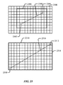
例示的な動的探索ウィンドウを図23に示す。第1の2Dグリッド2300は、エンドポイント2302および2304を指定した。動的探索ウィンドウ2306は、エンドポイントのそれぞれの位置と、その間の絶対距離2308とに基づいて設定される。この例では、相関余因子を生成するために必要とされる計算量を低減させるために、探索ウィンドウ2306はグリッド全体よりも小さくなるように設定される。いくつかの例では、ルーティングシステムは、エンドポイント間の絶対距離をまず算出し、次いで、その距離を使用して、動的ウィンドウ2306の好ましいエリアの決定を促す。次いで、それらのポイントを包含し、(ホットスポットなどを回避するために必要とされる可能性がある何らかの逆方向バックトラッキングに対応するように)利用可能な場合、ルーティングのために追加の水平空間および垂直空間を提供するために、エンドポイントの位置に基づいてウィンドウ2306の垂直境界および水平境界が設定される。図23はまた、エンドポイント2310および2312が2Dグリッド2314の境界に位置する例を提供する。したがって、グリッドのサイズを考慮すると、エンドポイント間の絶対距離2316はその最高であり、したがって、生じる動的ウィンドウ2318は、示すように、グリッド全体を包含する。図23の例は矩形ウィンドウを示すが、ウィンドウのエリアをさらに低減させ、したがって、計算上の負担も低減させるために、切頭角(truncated corners)を有するウィンドウなど、他のウィンドウ形状を用いることも可能であることを理解されたい。
An exemplary dynamic search window is shown in FIG. The
図22に戻ると、探索ウィンドウが指定されると、ルーティングシステムは、探索ウィンドウ内のノードに対応する共分散行列の係数に基づいて、2208で、相関余因子を決定する。上で説明したように、ターゲットi,jに対するエリアPの相関余因子(CCp)は、2つの対応する係数に基づいて定義され得る。相関余因子が計数の積に基づくこの例では、CCp = cov(i,p) * cov(p,j)である。2210で、ルーティングシステムは、探索ウィンドウ内に位置するグリッドを介して予想されるルートを識別または選択し、このルートは、相関余因子と何らかの不利な温度点(たとえば、ホットスポット/コールドスポット)の位置とに基づくエンドポイント間の最高温度相関を有する。ホットスポットなどを考慮に入れながら、2Dグリッド内の1つまたは複数の予想されるルートを識別するための例示的な手順に関しては、上の図5以下の説明を参照されたい。 Returning to FIG. 22, when a search window is specified, the routing system determines a correlation factor at 2208 based on the coefficients of the covariance matrix corresponding to the nodes in the search window. As explained above, the correlation coefficient (CCp) of area P for targets i, j may be defined based on two corresponding coefficients. In this example, where the correlation cofactor is based on the product of counts, CCp = cov (i, p) * cov (p, j). At 2210, the routing system identifies or selects an expected route through a grid located within the search window, which route is associated with a cofactor and any adverse temperature point (e.g., hot spot / cold spot). It has the highest temperature correlation between endpoints based on location. See the description below FIG. 5 below for an exemplary procedure for identifying one or more expected routes in a 2D grid, taking into account hot spots and the like.
2212で、ルーティングシステムは、ベースライン単位長さ抵抗値と、所定の係数と、予想されるルートに関する時変温度シーケンスとに基づいて、2D単位長さ抵抗値(unit-length resistance value)を決定する。この点について、2Dサンプルの場合、単位長さ抵抗を、以下のように、温度勾配の関数として表すことができる。
runit(x,y,t) = ρ0・(1+β・T(x,y,t)) (6)
式中、ρ0は0℃における単位長さ抵抗であり、x,yは2D座標であり、βは抵抗の所定の温度係数(1/℃)である。2つの係数ρ0およびβは、場合によっては、従来の技法を使用して、測定または取得され得る。埋め込み経路d(Mti, Sk)が固定されるとき、抵抗は次のように算出され得る:
R(Mti, Sk) = Σ∀e∈d(Mti, Sk))E[runit(e)]・len(e) (7)
式中、E[runit(x,y)]は、エッジe(Mti, Sk)内の抵抗の平均値であり、dは適用可能な距離である。
At 2212, the routing system determines a 2D unit-length resistance value based on a baseline unit length resistance value, a predetermined factor, and a time-varying temperature sequence for the expected route. To do. In this regard, in the case of 2D samples, the unit length resistance can be expressed as a function of the temperature gradient as follows:
r unit (x, y, t) = ρ 0・ (1 + β ・ T (x, y, t)) (6)
In the equation, ρ 0 is a unit length resistance at 0 ° C., x and y are 2D coordinates, and β is a predetermined temperature coefficient (1 / ° C.) of the resistance. The two coefficients ρ 0 and β may in some cases be measured or obtained using conventional techniques. When the embedded path d (M ti , S k ) is fixed, the resistance can be calculated as follows:
R (M ti , S k ) = Σ ∀e∈d (Mti, Sk)) E [r unit (e)] ・ len (e) (7)
In the equation, E [r unit (x, y)] is an average value of the resistance in the edge e (M ti , S k ), and d is an applicable distance.
2214で、ルーティングシステムは、抵抗値から最悪スキューを決定し、最悪スキューが大きすぎる場合、または、場合によっては、許容できない場合、予想されるルートを拒否する。たとえば、最悪スキューは、特定の回路アプリケーションに関する大きすぎるスキューを表す所定のしきい値に対して比較され得る。この点について、ソースノードs0からシンクsiまでの遅延D(s0_si)は、ノード電圧(波形)がソースノード内の衝撃励起の下でピーク電圧の100%を伝えるために必要とされる時間として定義され得る。所与のiに関して、第j番目のルーティング構成Confijのソースからシンクまでの遅延を取得した後、Confijに対応する最悪スキューは、次のように算出または推定され得る。 At 2214, the routing system determines the worst skew from the resistance value and rejects the expected route if the worst skew is too large or in some cases unacceptable. For example, the worst skew may be compared against a predetermined threshold that represents too much skew for a particular circuit application. In this regard, the delay D (s0_si) from the source node s0 to the sink si is defined as the time required for the node voltage (waveform) to carry 100% of the peak voltage under shock excitation in the source node. Can be done. For a given i, after obtaining the delay from the source to the sink of the jth routing configuration Conf ij , the worst skew corresponding to Conf ij may be calculated or estimated as follows:
述べたように、予想されるルートに関する最悪スキューはしきい値に対して比較され、大きすぎる場合、拒否され得る。ルートが拒否された場合、処理は(図の破線によって示すように)ブロック2210に戻り、スキュー問題を回避する代替のルートを識別することができる。代替で、識別された予想されるルートが許容される最悪スキューを有することがすでに保証されるように、最悪スキューは、システムが可能なルートを位置付ける(mapping out)間に、ブロック2210の手順の間に評価され、明らかにされ得る。したがって、図22および図23は、調整可能なウィンドウと最悪スキュー決定の両方が活用される一例を示す。他の例では、これらの特徴のうちの1つだけが活用され、他の特徴が活用され、または、これらの特徴のいずれも活用されない。
As stated, the worst skew for an expected route is compared against a threshold and can be rejected if it is too large. If the route is rejected, processing can return to block 2210 (as indicated by the dashed line in the figure) to identify an alternative route that avoids the skew problem. Alternatively, the worst-case skew is determined by the procedure of
図24は、ルーティングがRC結合を考慮に入れる、適切に装備されたルーティングシステムによって実行され得る例示的なルーティング手順2400を示す。前の例と同様、極端な温度位置の位置など、他の要因を考慮に入れることができる。2402で、ルーティングシステムは、基板層内のN個のノードの2Dグリッドを指定し、その2Dグリッドをモデル化して、N個の時変温度シーケンスのセットを生成する。2404で、ルーティングシステムは、時変温度シーケンスに基づいて、ノードの中から共分散行列を決定する。2406で、ルーティングシステムは、(動的であり得る)2Dグリッド内の探索ウィンドウを指定し、少なくとももう1つの配線ルートを有する基板に追加するためにグリッドを介して新しい配線ルートのためのエンドポイントの対を選択する。図2408で、ルーティングシステムは、探索ウィンドウ内のノードに対応する共分散行列の係数に基づいて、相関余因子を決定する。2410で、ルーティングシステムは、探索ウィンドウ内に位置するグリッドを介して、新しいラインに関して予想されるルートを識別または選択し、このルートは、相関余因子、および何らかの極端な温度点の位置などに基づくエンドポイント間の最高温度相関を有する。2412で、ルーティングデバイスは、予想される新しい2Dルートと他の2D配線ルートとの間のRC結合量を決定する。
FIG. 24 shows an
図25は、新しいルート2502がエンドポイント2506をエンドポイント2508に接続することを目的とする、2Dグリッド2504内の配線ルート2500と予想される新しいルート2502との間の例示的なRC結合を示す。この例では、予想される新しいルート2502はその長さの一部分にわたって、他の配線ルート2500と平行して位置し、矢印2510によって概して示されるRC結合をトリガする。
FIG. 25 illustrates an example RC coupling between a
図24を参照すると、ルーティングデバイスは、2414で、場合によっては、経路の隣接部分間の距離、ならびにレイヤの材料を考慮に入れることができる従来のRC結合評価または推定技法を使用して、予想される新しいルートと他のラインとの間のRC結合量を決定することができる。2414で、RC結合量が大きすぎる場合、またはさもなければ、許容できない場合、ルーティングシステムは予想されるルートを拒否する。たとえば、予想されるRC結合量は、特定の回路アプリケーションにとって大きすぎる量の結合(すなわち、新しいラインに沿った信号の伝搬に過度に影響し、許容できないスキューまたは他の所望されない影響を引き起こす結合)を表す所定のしきい値に対して比較され得る。予想されるルートが拒否される場合、処理は、次いで、(破線によって示す)ブロック2410に戻り、たとえば、他のワイヤに隣接して位置しないルートに従うことによって、RC結合問題を回避する代替の予想されるルートを識別することができる。代替で、ブロック2410で識別された、予想されるルートが他のワイヤと許容される少量の結合を有することがすでに保証されるように、RC結合は、システムが可能なルートをマッピングする間に、ブロック2410の手順の間に評価され、明らかにされ得る。
Referring to FIG. 24, the routing device predicts at 2414, possibly using conventional RC coupling estimation or estimation techniques that can take into account the distance between adjacent portions of the path, as well as the material of the layer. The amount of RC coupling between the new route and other lines can be determined. At 2414, if the RC coupling amount is too large or otherwise unacceptable, the routing system rejects the expected route. For example, the expected amount of RC coupling is too large for a particular circuit application (i.e., coupling that excessively affects signal propagation along the new line and causes unacceptable skew or other unwanted effects) Can be compared against a predetermined threshold representing. If the expected route is rejected, the process then returns to block 2410 (indicated by a dashed line), for example, an alternative prediction that avoids the RC coupling problem by following routes that are not located adjacent to other wires. Route to be identified. Alternatively, RC coupling is performed while the system maps possible routes so that the expected route identified in
今説明した2D特徴のうちのいくつかは、概して、マルチレイヤ(すなわち、3D)実装形態にも適用可能である。以下のセクションでは、マルチレイヤ3D例に関して、これらの特徴および他の特徴の例を説明する。 Some of the 2D features just described are generally applicable to multi-layer (ie, 3D) implementations. The following sections describe examples of these and other features with respect to the multi-layer 3D example.
3D実装形態に適用可能な追加の例示的な特徴
図26〜図32を参照すると、次に3D実装形態に適用可能である追加のまたは代替の特徴を説明する。これらの特徴のうちの少なくともいくつかは、上ですでに説明した手順を活用するか、または組み込んでいる。簡潔のために、これらの手順は、いずれかの差異を強調する以外、再度詳細に説明されない。
Additional Exemplary Features Applicable to 3D Implementations Referring to FIGS. 26-32, additional or alternative features applicable to 3D implementations will now be described. At least some of these features take advantage of or incorporate the procedures already described above. For the sake of brevity, these procedures will not be described in detail again, except to highlight any differences.
図26は、適切に装備されたルーティングシステムによって実行され得る追加の3D時変(すなわち、時間的可変)ルーティング特徴の概要を提供する。2602で、ルーティングシステムは、たとえば、上で論じたような、確率プロセスモデル化またはランダムプロセスモデル化を使用して、マルチレイヤ基板に関する3D時変空間相関マップを生成する(確率は、ランダムに決定されること、または統計的に解析され得るが、正確に予測され得ないランダムな確率パターンを有することを意味する)。2604で、ルーティングシステムは、3D空間相関マップに基づいて、マルチレイヤ基板に関する相関余因子を決定する。下でいくつかの例について説明する。2606で、ルーティングシステムは、相関余因子と、最悪スキュー、層密度、RC結合、不利な温度位置(たとえば、ホットスポット位置)、ビア位置、調整可能な動的ウィンドウ、およびレイヤベースの重み係数など、他の要因とに基づいて、マルチレイヤ基板内の好ましいまたは最適な配線経路(たとえば、「最も平滑な」ルート)を決定する。これらの要因のうちのいくつかの使用の例示的な例を下で提供する。2608で、ルーティングシステムは、次いで、ルーティングが完了すると、デバイス作製を許可するために、マルチレイヤ基板内の他の経路のための他の配線ルートを決定する。この点について、典型的なICは、その各々がブロック2606の様々な要因を考慮に入れることによってルーティングされ得る、数百または数千の配線経路を有し得る。
FIG. 26 provides an overview of additional 3D time-varying (ie, time-varying) routing features that can be performed by a properly equipped routing system. At 2602, the routing system generates a 3D time-varying spatial correlation map for the multilayer substrate using, for example, stochastic process modeling or random process modeling, as discussed above (probabilities are determined randomly). Or a random probability pattern that can be statistically analyzed but cannot be accurately predicted). At 2604, the routing system determines a cofactor for the multilayer substrate based on the 3D spatial correlation map. Some examples are described below. In 2606, the routing system can use cofactors, worst-case skew, layer density, RC coupling, adverse temperature locations (e.g., hot spot locations), via locations, adjustable dynamic windows, and layer-based weighting factors, etc. Based on other factors, determine a preferred or optimal wiring path (eg, “smooth” route) within the multilayer substrate. Illustrative examples of the use of some of these factors are provided below. At 2608, the routing system then determines other wiring routes for other paths in the multilayer substrate to allow device fabrication once routing is complete. In this regard, a typical IC may have hundreds or thousands of wiring paths, each of which can be routed by taking into account various factors of
図27は、この例では、3つのレイヤ2702、2704、および2706を有する例示的な3Dマルチレイヤ積層基板2700を示す。異なるレイヤ上のエンドポイント2710および2712の対の間で3D配線経路2708が接続される。示すように、配線経路は、様々なホットスポット/コールドスポット2714を回避しながら、3つのレイヤの各々の部分を横断する。あるレイヤから別のレイヤへの接続は、レイヤ間に伝導経路を提供するビア(別個に図示されず)を介して配線経路をルーティングすることによって達成される。
FIG. 27 shows an exemplary 3D multi-layer
図28は、3D実装形態のための余因子行列を生成し、使用する一例を示す。この3D実装形態のいくつかの態様は、図6の2D実装形態の対応する態様と同じであるか、または同様であり、したがって、再度詳細に説明しない。すでに説明したように、高温度変動は、配線ルートに関連する遅延およびスキューに著しい影響を及ぼし得る。2D温度認識ルーティングと同様、3D温度認識ルーティングは、各ノード間の遅延を評価し、スキューおよびスキュー変動をやはり低減させるために、距離と温度相関の両方を考慮することができる。経時的な動的温度差は異なるスキューを生成するため、3Dルーティング方式は、より安定したスキュー変動の保証または達成を試みる際に、温度の視点から、最も平滑なルーティング経路を識別することができる。すなわち、3Dルーティング方式は、3D空間相関および3D時間相関とともに、時変温度差を考慮する。3D時変温度マップを解析することによって、3D温度相関マップが次いで生成される。このようにして、3Dルーティング方式は、最高相関余因数値を有するマルチレイヤルートを識別し、それによって、より良好な熱耐性を有するルートを識別することができる。加えて、温度相関マップ内で識別された何らかのホットスポット/コールドスポットエリアを回避することによって、3Dルーティング方式はスキューをさらに低減させることができる。 FIG. 28 shows an example of generating and using a cofactor matrix for a 3D implementation. Some aspects of this 3D implementation are the same as or similar to the corresponding aspects of the 2D implementation of FIG. 6, and therefore will not be described in detail again. As already explained, high temperature fluctuations can significantly affect the delay and skew associated with the wiring route. Similar to 2D temperature aware routing, 3D temperature aware routing can consider both distance and temperature correlation to evaluate the delay between each node and also reduce skew and skew variation. Because dynamic temperature differences over time generate different skews, 3D routing schemes can identify the smoothest routing path from a temperature perspective when attempting to guarantee or achieve more stable skew fluctuations . That is, the 3D routing scheme considers time-varying temperature differences as well as 3D spatial correlation and 3D temporal correlation. By analyzing the 3D time varying temperature map, a 3D temperature correlation map is then generated. In this way, the 3D routing scheme can identify the multilayer route with the highest correlation factor value, thereby identifying the route with better heat tolerance. In addition, by avoiding any hot spot / cold spot area identified in the temperature correlation map, the 3D routing scheme can further reduce skew.
全体的な回路設計プロセス2800は、回路の動作が熱を生じ得る、PCB、IC、または何らかの他の適切なマルチレイヤ構造2803のエリア2802内の1つもしくは複数の回路2801を位置特定することによって始まる。図28の例では、回路2801は、マルチレイヤ構造2803のすべてのレイヤにわたって潜在的に延長するとして示されている。この3D例では、エリア2802は基板内の体積に対応し得ることに留意されたい。「エリア」という用語は、上の説明に一致するように使用される。グリッドパターンは、回路2801内、かつ回路2801の周囲に延長する、マルチレイヤ構造2803のエリア2802内に示されている。このパターンは、基板自体の実際の構成要素または特徴ではないことを理解されたい。むしろ、このパターンは、ルーティングシステムのソフトウェアがルーティング経路を決定する際に使用するために構造をどのように再分割することができるかを示す。グリッドは、概して、任意のサイズ、形状、および粒度のものであってよい。実際には、図28に示すよりもさらに細かい粒度を有するグリッドが用いられる。代わりに、非矩形グリッドを潜在的に使用することができるが、矩形グリッドは、特に、マンハッタンルーティングが用いられるとき、処理のためにより便利である。実際のマルチレイヤ構造2803は示された部分よりもさらに大きい場合があることをやはり理解されたい。たとえば、エリア2802は、作製されるIC全体の1つの比較的小さい部分だけを表す場合がある。単一の回路2801だけがエリア2802内に示されているが、エリア内に複数の回路を提供することが可能である。
The overall
次いで、エリア2802に関して3D空間温度解析2804が実行される。上の2Dの例と同様、これは、ある時間期間にわたってエリア2802の異なるポイントにおける温度を決定すること(たとえば、推定すること)を必要とし得る。説明したように、考慮中の回路エリア内に位置する回路の温度特性に関する情報、およびこれらの回路がどのように構成されているかに関する情報を有するシミュレーションプログラムは、回路が動作中であるとき、エリア2802内の様々なポイントにおいて予想される温度を推定することができる。エリア2802内の回路の近傍にある時変温度をモデル化するために、前述のグリッドに、測定または熱シミュレーションによって取得され得る温度範囲を割り当てることができる。
A 3D
特定の非限定的な例として、3D温度解析2804は、マイクロアーキテクチャレベルの電力および温度シミュレーションを必要とし得る。エリア2802は、マルチレイヤ基板のレイヤkごとにいくつかのノードを有する均一のグリッドに分割される。一般に、レイヤkに関して、NK個のノードが存在することになる。したがって、マルチレイヤエリア2802内に
As a specific, non-limiting example,
個のノードが存在し、式中、Kはレイヤの総数である。温度解析2804によって生成された温度シーケンスを次のように表すことができる。
There are n nodes, where K is the total number of layers. The temperature sequence generated by the
図28は、時間インスタンスt1から Figure 28 shows the time instance from t 1
![]()
![]()
に対する温度行列2806をもたらす簡略化された例を示す。非限定的な例では、温度行列2806は式9に対応する。相関算出2808は、マルチレイヤ基板のK個の層に基づいて、相関行列2810を生成するための入力として3D温度行列2806を使用する。非限定的な例では、相関算出2808は、
A simplified example yielding a
によって表される(サイズ Represented by (size
の)温度相関行列または共分散行列を生成し、
式中、
A) temperature correlation matrix or covariance matrix
Where
はノード間の共分散行列であり、式中、 Is the covariance matrix between nodes, where
は、ノードniおよびnjに関する標準偏差である。この例では、図28の3D相関行列2810は、したがって、式10に対応することになる。
Is the standard deviation for nodes n i and n j . In this example, the
余因子算出2812は、ルートのために指定された3Dターゲットポイント(たとえば、マルチレイヤ基板内のエンドポイント)に関連する(K個のレイヤに基づく)余因子行列2814を生成するための入力として3D相関行列2810を使用する。上の2Dの例にあるように、高い相関余因子を有する3Dグリッド内のポイントは、両方のルーティングターゲットポイントとの高い相関を表す。いくつかの実装形態では、相関余因子は、2つのターゲットポイントに関連する係数の積に基づく: CCpk = cov(ik,pk) * cov(pk,jk)であり、式中、pkは、pがk個のレイヤのうちのいずれか1つの中にあり得ることを示す。他の実装形態では、相関余因子は係数の和に基づく、CCpk = cov(ik,p) + cov(p,jk)。3Dグリッド内の2つのターゲットポイントを有する3Dグリッド内のポイントの相関を示すのに役立つ他のアルゴリズムまたは手順も同様に使用され得る。
その後、3D温度認識ルーティング2816は、最高相関値を有する3Dルート2818を識別するための入力として余因子行列2814を使用する。たとえば、3D温度認識ルーティング2816は、マルチレイヤ基板内の2つのターゲットポイント間の各予想される3Dルートに関する相関値を算出することができる。2Dの事例同様、ルートに関する相関値は、そのルートに沿った3Dグリッドポイントに関連する個々の余因子値の関数である。たとえば、その3Dルートに関する相関値を生成するために、個々の余因子値は、一緒に乗算され、一緒に加算され、または何らかの他の方法で演算され得る。設計目的に応じて、(たとえば、3D迷路ルーティングなど)様々な3D実装形態で様々なタイプの3Dルーティングアルゴリズムを用いることができる。温度認識ルーティングは、マンハッタンルーティング規則または他のルーティング規則を用いることができる。したがって、ルーティングは「右側」ルーティング選定に制限されなくてよく、または画定されたルーティングウィンドウ内に留まるように制限されなくてもよい。したがって、これが3Dルートのために優れたスキュー特性をもたらす3Dシナリオでは、コース反転(たとえば、バックトラッキング)を用いることもできる。その上、3D温度認識ルーティング2816は、RC結合、最悪スキュー、層密度、重み係数など、図26に記載したルーティング係数のうちの1つまたは複数を考慮に入れることができる。
Thereafter, the 3D
重み係数が考慮される限り、図9〜図11を参照して上で説明したように、最終的なルーティング判定は、様々な重み係数を使用して物理的要因を考慮に入れることができる。重み係数をあるレイヤから別のレイヤへの遷移、ビアの使用、コース反転、または他の物理的要因と関連付けることができる。これらの物理的要因は、3Dルートに関連する信号スキュー、電力消費、または何らかの他の動作パラメータに影響を及ぼし得る。したがって、2816で、1つまたは複数の重み係数を使用して、そのような影響を定量化することができる。(たとえば、最低スキューを有する3Dルート、別の3Dルートのスキューと最も整合するスキューを提供する3Dルート、最低電力消費を有する3Dルートなど)好ましい、または最適な3Dルートの決定は、温度相関と他の重み係数の平衡に基づき得る。様々な例について、図9〜図11およびその説明を参照されたい。 As long as the weighting factor is taken into account, the final routing decision can take into account physical factors using various weighting factors, as described above with reference to FIGS. Weighting factors can be associated with transitions from one layer to another, the use of vias, course reversal, or other physical factors. These physical factors can affect signal skew, power consumption, or some other operating parameter associated with the 3D route. Accordingly, at 2816, one or more weighting factors can be used to quantify such effects. (E.g. 3D route with lowest skew, 3D route that provides skew that best matches the skew of another 3D route, 3D route with lowest power consumption, etc.) It may be based on the balance of other weight factors. Refer to FIGS. 9-11 and their descriptions for various examples.
図29は、3Dルーティングが最悪スキュー推定を考慮に入れ、マルチレイヤ基板のレイヤのうちの少なくともいくつかの中の動的探索ウィンドウを活用する、適切に装備された3Dルーティングシステムによって実行され得る例示的なルーティング手順2900を示す。ホットスポットの位置など、他の要因を考慮に入れることもできる。2902で、3Dルーティングシステムは、基板層内のNK個のノードの3Dグリッドを指定し、その3Dグリッドをモデル化して、述べたように、
FIG. 29 illustrates an example where 3D routing can be performed by a suitably equipped 3D routing system that takes into account worst skew estimation and exploits a dynamic search window in at least some of the layers of the multi-layer board A
であるNK個の時変温度シーケンスのセットを生成する。式9に関して上で説明した手順を使用して、NK個のノードのグリッドを生成し、時変温度シーケンスを生成することができる。2904で、3Dルーティングシステムは、たとえば、上で式10〜式12で示したように、時変温度シーケンスに基づいて、ノードの中から共分散行列を決定する。2906で、3Dルーティングシステムは、3Dグリッドの各レイヤk内の動的に調整可能な探索ウィンドウを指定し、1つまたは複数のビアを必要とし得る、グリッドを介して3Dルートを配線するための3Dグリッド内のエンドポイントの対を選択する。
Generate a set of N K time-varying temperature sequences. Using the procedure described above with respect to
3つの例示的な動的探索ウィンドウのセットを図30に示す。この例では、3Dグリッド3000は、3つの積層レイヤ30001、30002、および30003を含み、指定されたエンドポイント3002および3004を有する。第1の動的探索ウィンドウ30061は上位レイヤ30001に関して設定され、第2の動的探索ウィンドウ30062は中間レイヤ30002に関して設定され、第3の動的探索ウィンドウ30063は下位レイヤ30003に関して設定される。示すように、探索ウィンドウは各レイヤに関して異なるサイズを有し得る。探索ウィンドウの相対サイズは、2つのエンドポイントのそれぞれの位置と、それらの間の絶対距離3008とに基づいて、ルーティングシステムによって設定され得る。この例では、上位レイヤならびに下位レイヤの探索ウィンドウ30061および30063は、中間レイヤの探索ウィンドウ30062よりも小さい。相関余因子を生成するために必要とされる計算量を低減させるために、すべての3つの探索ウィンドウはグリッド全体よりも小さくなるように設定される。上の2D例と同様に、3Dルーティングシステムは、まずエンドポイント間の絶対距離を算出し、その距離を使用して、3つの動的ウィンドウ(30061、30062、および30063)の各々の好ましいエリアを決定するのを促す。次いで、それらのエンドポイントを包含し、(たとえば、ホットスポットなどを回避するために必要とされ得る何らかのバックトラッキングに対応するために)ルーティングのためのそれらのレイヤのうちの少なくともいくつかの上に追加の水平空間および垂直空間を提供するために、それらのエンドポイントの位置に基づいて、3つのウィンドウの各々の垂直境界および水平境界が設定される。図30の例は矩形の探索ウィンドウを示すが、ここでも少なくともいくつかの例では、他のウィンドウ形状を用いることが可能であることを理解されたい。
A set of three exemplary dynamic search windows is shown in FIG. In this example, the
図29に戻ると、各探索ウィンドウが指定されると、2908で、3Dルーティングシステムは、各レイヤの探索ウィンドウ内のノードに対応する共分散行列の係数に基づいて相関余因子を決定する。上で説明したように、ターゲットik, jkに対するエリアP内の相関余因子(CCpk)は、2つの対応する係数に基づいて定義され得る。相関余因子が計数の積に基づく例では、CCpk = cov(ik,p) * cov(p,jk)である。2910で、3Dルーティングシステムは、探索ウィンドウ内に位置するグリッドを介して、予想される3Dルートを識別または選択し、このルートは、相関余因子と、何らかの不利な温度点(たとえば、ホットスポット/コールドスポット)および何らのビアの位置とに基づくエンドポイント間の最高温度相関を有する。ホットスポットなどを考慮に入れながら、3Dグリッド内の1つまたは複数の予想されるルートを識別するための例示的な手順に関しては、図28の説明を参照されたい。 Returning to FIG. 29, once each search window is specified, at 2908, the 3D routing system determines a covariance factor based on the coefficients of the covariance matrix corresponding to the nodes in the search window of each layer. As explained above, the correlation factor (CCp k ) in area P for targets i k , j k can be defined based on two corresponding coefficients. In an example where the correlation cofactor is based on the product of counts, CCp k = cov (i k , p) * cov (p, j k ). At 2910, the 3D routing system identifies or selects an expected 3D route via a grid located within the search window, which route is associated with a cofactor and some adverse temperature point (e.g., hot spot / It has the highest temperature correlation between the endpoints based on the cold spot) and any via location. See the description of FIG. 28 for an exemplary procedure for identifying one or more expected routes in a 3D grid, taking into account hot spots and the like.
2912で、3Dルーティングシステムは、ビアの存在をやはり考慮に入れながら、ベースライン単位長さ抵抗値と、所定の係数と、予想される3Dルートに関する時変温度シーケンスとに基づいて、3D単位長さ抵抗値を決定する。この点について、3D例では、単位長さ抵抗を、次のように、温度勾配の関数として表すことができる。
runit(x,y,k,t)=ρ0・(1+β・T(x,y,k,t)) (13)
式中、ρ0は、ここでも、0℃における単位長さ抵抗であり、x,y,kは3D座標であり、βは抵抗の所定の温度係数(1/℃)である。第k番目のレイヤと第(k-1)番目のレイヤとの間のビアの抵抗は、
rvia(k) (14)
を使用して表すことができる。
K個のレイヤを有する基板の場合、(レイヤごとに1つのビアを仮定すると)(K-1)個の異なるrvia値が存在することになる。その場合、D経路上の抵抗は、たとえば、次のように計算され得る。
In 2912, the 3D routing system takes the 3D unit length based on the baseline unit length resistance value, the given factor, and the time-varying temperature sequence for the expected 3D route, still taking into account the presence of vias. Determine the resistance value. In this regard, in the 3D example, the unit length resistance can be expressed as a function of the temperature gradient as follows:
r unit (x, y, k, t) = ρ 0・ (1 + β ・ T (x, y, k, t)) (13)
Where ρ 0 is again the unit length resistance at 0 ° C., x, y, k are 3D coordinates, and β is the predetermined temperature coefficient (1 / ° C.) of the resistance. The via resistance between the kth layer and the (k-1) th layer is
rvia (k) (14)
Can be used to express.
For a substrate with K layers, (K-1) different rvia values exist (assuming one via per layer). In that case, the resistance on the D path can be calculated, for example, as follows.
式中、αはビアの存在を示す(ビアがない場合、α=0、1つのビアの場合、α=1)。温度影響による抵抗が決定された後、ルーティングシステムは、次いで、図22の2D最悪スキュー例に関して上に記載した技法と同様の技法を使用して、クロックスキューおよびその変動を算出または推定することができる。たとえば、式8およびその説明を参照されたい。 In the formula, α indicates the presence of a via (α = 0 when there is no via, α = 1 when there is one via). After the resistance due to temperature effects is determined, the routing system may then calculate or estimate the clock skew and its variations using techniques similar to those described above for the 2D worst skew example of FIG. it can. For example, see Equation 8 and its description.
2914で、ルーティングシステムは、抵抗値から最悪スキューを決定し、最悪スキューが大きすぎる場合、または、場合によっては、許容できない場合、予想される3Dルートを拒否する。この場合も、一例として、最悪スキューは所定のしきい値に対して比較され得る。予想されるルートが拒否された場合、処理は(図の破線矢印によって示すように)ブロック2910に戻り、スキュー問題を回避する代替の3Dルートを識別することができる。代替で、識別された、予想される3Dルートが許容される最悪スキューを有することがすでに保証されるように、最悪スキューは、3Dシステムが可能なルートを位置付ける間に、ブロック2910の手順の間に評価され、明らかにされ得る。 At 2914, the routing system determines the worst skew from the resistance value and rejects the expected 3D route if the worst skew is too large or possibly unacceptable. Again, as an example, the worst skew can be compared against a predetermined threshold. If the expected route is rejected, processing can return to block 2910 (as indicated by the dashed arrows in the figure) to identify an alternative 3D route that avoids the skew problem. Alternatively, the worst skew is determined during the procedure of block 2910 while the 3D system locates a possible route so that the identified and expected 3D route is already guaranteed to have the worst skew allowed. Can be evaluated and revealed.
図31は、ルーティングが、マルチレイヤ基板の異なるレイヤ上の配線ルートのRC結合、ならびに層密度を考慮に入れる、適切に装備されたルーティングシステムによって実行され得る例示的な3Dルーティング手順3100を示す。前の例と同様、ホットスポットの位置など、他の要因を考慮に入れることができる。3102で、3Dルーティングシステムは、少なくとももう1つのラインと、潜在的に多くの他のラインとを有するマルチレイヤ基板内のNK個のノードの3Dグリッドを指定し、3Dグリッドをモデル化して、NK個の時変温度シーケンスのセットを生成する。3104で、3Dルーティングシステムは、時変温度シーケンスに基づいて、ノードの中から共分散行列を決定する。3106で、3Dルーティングシステムは、他のラインともに追加されることになる、グリッドを介した新しい配線ルートのためのエンドポイントの対を選択する。図31には示されていないが、ルーティングシステムは、すでに説明したように様々な探索ウィンドウを使用することができる。また、3106で、ルーティングシステムは、マルチレイヤ基板の層の各々の密度、たとえば、特定のレイヤ上に作製されると予想されるワイヤの数、およびそれらのワイヤの長さを決定する。すなわち、層密度は、概して、特定のレイヤ上に堆積されることが予想される金属の総量を指す場合がある。たとえば、特定のレイヤが、現在、そのレイヤ上に作製するために指定された何のワイヤも有さない場合、層密度は低いと見なされる(また、ゼロの密度によって表され得る)。しかしながら、特定のレイヤが(ルーティング手順の前の反復の結果として)そのレイヤ上に作製するために指定された多数のワイヤを現在有する場合、密度は高いと見なされ、その場合、層密度は、そのレイヤのためのワイヤの数およびそのレイヤ上のそれらのワイヤの全長の和として定量化され得る。層密度を定量化するために、他の好適な技法を使用することが可能である。層密度は重要であり得るが、これは、いくつかの例では、比較的高い密度を有するレイヤを回避しながら、比較的低い密度を有するレイヤ上に新しい予想されるラインをルーティングすることが適切な場合があるためである。その上、高い密度を有するレイヤに隣接して位置しないレイヤ上に新しい予想されるラインをルーティングすることは、隣接するレイヤのワイヤとのRC結合をもたらし得るため、そのようなルーティングは望ましい場合がある。加えて、または代替で、その材料密度がRC結合に影響を及ぼす場合、層密度は特定のレイヤの材料密度を表し得る。さらにまた、単位高さ当たりのレイヤの数はやはりRC結合に影響を及ぼす可能性があるため、層密度は単位高さ当たりのレイヤの数を表し得る。
FIG. 31 shows an exemplary
3108で、3Dルーティングシステムは、各レイヤの探索ウィンドウ内のノードに対応する共分散行列の係数に基づいて、相関余因子を決定する。3110で、3Dルーティングシステムは、様々な探索ウィンドウ内に位置するグリッドを介して、新しいラインに関して予想される3Dルートを識別または選択し、このルートは、レイヤのそれぞれの密度をやはり考慮に入れながら、相関余因子、および何らかの極端な温度点の位置などに基づくエンドポイント間の最高温度相関を有する。述べたように、ルーティングシステムは、比較的高い密度のレイヤを回避するルートを優先し得る。3112で、3Dルーティングデバイスは、予想される新しい3Dルートと他の2Dラインまたは3Dラインとの間のRC結合量を決定する。 At 3108, the 3D routing system determines a covariance factor based on the coefficients of the covariance matrix corresponding to the nodes in the search window of each layer. At 3110, the 3D routing system identifies or selects an expected 3D route for the new line via grids located within the various search windows, while still taking into account the respective densities of the layers. The highest temperature correlation between endpoints based on, for example, the cofactor, and the location of some extreme temperature points. As stated, the routing system may prefer routes that avoid relatively high density layers. At 3112, the 3D routing device determines the amount of RC coupling between the expected new 3D route and the other 2D line or 3D line.
図32は、新しいライン3202がエンドポイント3206および3208との間を接続することを目的とする、3Dグリッド3204内のライン3200と予想される新しい3Dライン3202との間の例示的なRC結合を示す。この例では、予想される新しい3Dルート3202は、そのルートの一部分にわたって他のライン3200と平行し、かつその1レイヤ上に位置し、矢印3210によって概して示されるRC結合をトリガする。この図はまた、回避すべき様々なホットスポット3212を示す。図32はまた、異なる層密度のレイヤを示すのに役立つ。この例では、最上レイヤ3214は(予想されるルート3202が設計の一部として容認される前に)ゼロの密度を有するが、これは、そのレイヤ上に他のラインまたはラインの一部が存在しないためである。最下レイヤ3216は、比較的低い(しかし、非ゼロ)密度を有するが、これはライン3200の比較的短い部分がそのレイヤを通過するためである。中間レイヤ3218は、比較的高い密度を有するが、これはライン3200のより長い部分がそのレイヤを通過するためである。したがって、最下レイヤ3216よりも中間レイヤ3218内により多くの金属が存在する。実際的な実装形態では、ルーティングシステムの多数の反復の後、基板の様々なレイヤ上で作製するために多数のラインまたはラインの一部を指定することができ、したがって、レイヤのうちのいくつかの密度は非常に高い場合がある。
FIG. 32 shows an exemplary RC coupling between
図31に戻ると、3Dルーティングデバイスは、場合によっては、配線経路の隣接する部分間の距離、および異なるレイヤ間の材料内の任意の差分、ならびに前述の層密度を考慮に入れることができる従来のRC結合評価技法または推定技法を使用して、3114で、予想される新しい3Dルートと他の隣接するライン(もしあれば)との間のRC結合量を決定することができる。3114で、RC結合量が大きすぎる場合、ルーティングシステムは予想されるルートを拒否する。たとえば、予想されるRC結合量は、特定の回路アプリケーションにとって大きすぎる結合(すなわち、新しいラインに沿った信号の伝搬に過度に影響し、許容できないスキューまたは他の所望されない影響を引き起こす結合)を表す所定のしきい値に対して比較され得る。予想されるルートが拒否される場合、処理は、次いで、(図の破線矢印を介して)ブロック3110に戻り、たとえば、他のワイヤに隣接して位置しないか、または高密度のレイヤを回避するルートに従うことによって、RC結合問題を回避する代替の予想されるルートを識別することができる。代替で、ブロック3110で識別された予想されるルートが受付可能な程度に少量の結合を他のワイヤと有することがすでに保証されるように、RC結合は、システムが可能なルートをマッピングする間に、ブロック3110の手順の間に評価され、明らかにされ得る。
Returning to FIG. 31, the 3D routing device can in some cases take into account the distance between adjacent portions of the wiring path, and any differences in the material between different layers, as well as the aforementioned layer density. Using the RC coupling estimation or estimation techniques, the amount of RC coupling between the expected new 3D route and other adjacent lines (if any) can be determined at 3114. At 3114, if the RC coupling amount is too large, the routing system rejects the expected route. For example, the expected amount of RC coupling represents coupling that is too large for a particular circuit application (i.e. coupling that excessively affects signal propagation along the new line and causes unacceptable skew or other unwanted effects) It can be compared against a predetermined threshold. If the expected route is rejected, processing then returns to block 3110 (via the dashed arrows in the figure), for example, not located adjacent to other wires or avoiding dense layers By following the route, an alternative expected route that avoids the RC coupling problem can be identified. Alternatively, RC coupling is performed while the system maps possible routes so that the expected route identified in
例示的なシステムおよび方法
図33は、本開示の1つまたは複数の態様がアプリケーションを見出し得る回路設計システム3300の一例を示す。システム3300は、図17の対応するシステムと同様であるが、具体的には、3Dルーティングに適合し、したがって、関係する差異だけを詳細に説明する。システム3300は、ユーザディスプレイデバイス3304に通信可能に結合され、マルチレイヤ基板回路の3D表現を表示するように適合されたコンピュータ3302と、ユーザ入力デバイス3306とを含む。コンピュータ3302はまた、コンピュータ3302によって生成された3D設計データがPCB、ICなどを製造するマルチレイヤ回路作製システム3310に転送されることを可能にするために、ネットワーク3308に通信可能に結合される。コンピュータ3302は、プロセッサ3312とメモリ3314とを含む。
Exemplary Systems and Methods FIG. 33 illustrates an example
メモリ3314内に記憶され、かつ/またはプロセッサ3312によって実装される3Dルーティングプログラム3316および3Dシミュレーションモデル3318は、ユーザが本明細書の教示に従って3D回路設計を生成することを可能にする。たとえば、ユーザは、ディスプレイデバイス3304とユーザ入力デバイスとを使用して、本明細書で教示されるように、(たとえば、ICまたはPCBの)少なくとも1つのマルチレイヤ基板上に3D回路を配置し、少なくとも1つのマルチレイヤ基板上の様々な位置において3D温度特性を経時的にシミュレートし、相関行列を生成し、余因子行列を生成し、最良の温度相関を有する3Dルートを選択することができる。ユーザは、次いで、所望される回路構成要素を作り出すために、生じた3Dルート設計3320を作製システム3310に送ることができる。本明細書で説明する3D技法は、概して、適用可能な場合に、それの一部またはサブセットとして、2D技法を含むことに留意されたい。したがって、3Dルーティングプログラム3316は、2Dルート、ならびに3Dルートを処理することができる。同様に、3Dシミュレーションモデル3318は2Dモデルを処理することもでき、3Dルート設計3320は2Dルート設計を処理することもできる。したがって、図33および本明細書の他の図に示す3D構成要素は、3D回路または3D設計だけの処理に限定されない。
次に、図34を参照すると、本開示の少なくとも1つの例による、図33のコンピュータ3302などの、装置3400の選択された構成要素を示すブロック図を示す。装置3400は、図18の対応するシステムと同様であるが、具体的には、3Dルーティングに適合し、したがって、関係する差異だけを詳細に説明する。装置3400(たとえば、設計ツール)は、外部バスインターフェース3402と、記憶媒体3404と、ユーザインターフェース3406と、メモリデバイス3408と、処理回路3410とを含む。処理回路は、外部バスインターフェース3402、記憶媒体3404、ユーザインターフェース3406、およびメモリデバイス3408の各々と電気的に通信するように結合または配置される。外部バスインターフェース3402は、外部バス3412に対するインターフェースを装置3400の構成要素に提供する。処理回路3410は、データを取得、処理、および/または送り、データのアクセスおよび記憶を制御し、コマンドを発行し、他の所望の動作を制御するように構成される。場合によっては、処理回路3410は、プログラミングを実装することによって、あるいはプログラミングを実装することなく、所望の機能を実行するように適合された回路を含み得る。処理回路3410は、記憶媒体3404上に記憶されてもよいプログラミングの実行を含めて処理するように適合される。
Referring next to FIG. 34, a block diagram illustrating selected components of the
場合によっては、処理回路3410は、予想される3Dルートを識別するためのモジュール3414、予想される3Dルートの温度特性を決定するためのモジュール3416、予想される3Dルートのうちの1つを選択するためのモジュール3418、選択された3Dルートの表示を記憶するためのモジュール3420、ポイントの3Dグリッドを識別するためのモジュール3422、電子回路の温度特性を決定するためのモジュール3424、予想される3Dルートの距離を決定するためのモジュール3426、分岐を選択するためのモジュール3428、最悪スキューを決定するためのモジュール3425、層密度に基づいて、予想される3Dルートを識別するためのモジュール3427、(たとえば、2Dまたは3Dのいずれにおいても動作し得る)ウィンドウサイズを動的に調整するためのモジュール3429、および(たとえば、2Dまたは3Dのいずれにおいても動作し得る)RC結合に基づいて、予想されるルートを識別するためのモジュール3431のうちの1つもしくは複数を含み得る。
In some cases, the processing circuit 3410 selects one of a
予想される3Dルートを識別するためのモジュール3414は、3Dルーティングエリア内の2つ以上のターゲットポイントに関する情報を収集し、ターゲットポイント間の3Dルーティングエリア内を横断し得る異なる3Dルートを算出し、予想される3Dルートの表示を生成するように適合された回路および/またはプログラミング(たとえば、記憶媒体3404上に記憶された、予想される3Dルートを識別するためのモジュール3430)を含み得る。予想され3Dルートの温度特性を決定するためのモジュール3416は、予想される3Dルートに関する情報を獲得し、各予想される3Dルートに沿った様々なポイントの温度特性を算出し、温度特性の表示を生成するように適合された回路および/またはプログラミング(たとえば、記憶媒体3404上に記憶された、予想される3Dルートの温度特性を決定するためのモジュール3432)を含み得る。
A
予想される3Dルートのうちの1つを選択するためのモジュール3418は、予想される3Dルートの温度特性に関する情報を獲得し、異なる温度特性の中から最良の温度特性を識別し、その最良の温度特性に関連する3Dルートに関する情報を生成するように適合された回路および/またはプログラミング(たとえば、記憶媒体3404上に記憶された、予想される3Dルートのうちの1つを選択するためのモジュール3434)を含み得る。選択された3Dルートの表示を記憶するためのモジュール3420は、選択された3Dルートに関する情報を獲得し、選択された3Dルートを示す表示を生成し、その表示を含む信号を生成し、その信号をメモリデバイスに送るように適合された回路および/またはプログラミング(たとえば、記憶媒体3404上に記憶された、選択された3Dルートの表示を記憶するためのモジュール3436)を含み得る。
The
3Dポイントのグリッドを識別するためのモジュール3422は、1つもしくは複数の回路のための3Dルーティングエリアに関する情報を獲得し、そのエリア内の3Dポイントのグリッドを画定し、3Dポイントの画定されたグリッドの表示を生成するように適合された回路および/またはプログラミング(たとえば、記憶媒体3404上に記憶された、3Dポイントのグリッドを識別するためのモジュール3438)を含み得る。電子回路の温度特性を決定するためのモジュール3424は、電子回路に関する情報を獲得し、1つもしくは複数の動作条件の下で電子回路の温度特性を決定し、温度特性の表示を生成するように適合された回路および/またはプログラミング(たとえば、記憶媒体3404上に記憶された、電子回路の温度特性を決定するためのモジュール3440)を含み得る。予想される3Dルートの距離を決定するためのモジュール3426は、予想されるルートに関する情報を獲得し、予想されるルートの距離を算出し、予想されるルートの距離の表示を生成するように適合された回路および/またはプログラミング(たとえば、記憶媒体3404上に記憶された、予想されるルートの距離を決定するためのモジュール3442)を含み得る。分岐点を選択するためのモジュール3428は、ターゲットポイントに関する情報を獲得し、ターゲットポイント間の予想される分岐点を識別し、予想される分岐点のうちの1つを選択し、選択された分岐点を識別する表示を生成するように適合された回路および/またはプログラミング(たとえば、記憶媒体3404上に記憶された、分岐点を選択するためのモジュール3444)を含み得る。
A
最悪スキューを決定するためのモジュール3425は、電子回路に関する情報を獲得し、1つもしくは複数の動作条件の下で電子回路の最悪スキューを決定し、その最悪スキューの表示を生成するように適合された回路および/またはプログラミング(たとえば、記憶媒体3404上に記憶された、最悪スキューを決定するためのモジュール3445)を含み得る。層密度に基づいて予想される3Dルートを決定するためのモジュール3427は、予想される3Dルートに関する情報を獲得し、予想されるルートに関連するレイヤに関する層密度を算出し、その層密度に基づいて、予想される3Dルートの識別の表示を生成するように適合された回路および/またはプログラミング(たとえば、記憶媒体3404上に記憶された、層密度に基づいて予想される3Dルートを識別するためのモジュール3447)を含み得る。
ウィンドウサイズを動的に調整するためのモジュール3429は、ターゲットポイントに関する情報を獲得し、探索ウィンドウサイズを動的に識別および調整し、ウィンドウサイズの表示を生成するように適合された回路ならびに/またはプログラミング(たとえば、記憶媒体3404上に記憶された、ウィンドウサイズを動的に調整するためのモジュール3449)を含み得る。RC結合に基づいて予想されるルートを識別するためのモジュール3431は、RC結合に関する情報を獲得し、RC結合に基づいて、予想されるルートを識別し、RC結合および予想されるルートの表示を生成するように適合された回路および/またはプログラミング(たとえば、記憶媒体3404上に記憶された、RC結合に基づいて、予想されるルートを識別するためのモジュール3451)を含み得る。
A
図18の例と同様、記憶媒体3404は、プログラミング、電子データ、データベース、またはその他のデジタル情報を記憶するための、1つまたは複数のプロセッサ可読デバイスを表す場合がある。記憶媒体3404は、プログラミングを実行するときに処理回路3410によって操作されるデータを記憶するために使用されてもよい。記憶媒体3404は、可搬型または固定式記憶デバイスと、光記憶デバイスと、プログラミングの記憶、収容、および/または搬送が可能な様々なその他の媒体とを含む、処理回路3410によってアクセスすることが可能な任意の利用可能な媒体であってもよい。いくつかの実装形態では、記憶媒体は、非一時的(たとえば、有形の)記憶媒体であってよい。
Similar to the example of FIG. 18,
図35は、本開示のいくつかの態様による、ワイヤルーティングのためのプロセス3500を示す。プロセス3500は、回路設計ツールまたは何らかの他の適切な装置内に位置し得る処理回路3410(図34)内で行われ得る。別の態様では、処理3500は、図33に示す回路設計システム3300によって実装され得る。当然、本開示の範囲内の様々な態様では、プロセス3500は、ワイヤルーティング動作をサポートすることができる任意の適切な装置によって実装され得る。簡潔のために、このプロセスを実行するシステム、回路、または装置は、以下の説明において、単にシステムと呼ばれることになる。ブロック3502で、システムは、少なくとも1つの基板を介してワイヤをルーティングするための複数の予想されるルートを識別する。少なくとも1つの基板は、プリント回路基板の基板、集積回路ダイ基板、または何らかの他のタイプの基板を含み得る。ブロック3504で、システムは、予想されるルートの各々に関して、予想されるルートに関連する時変温度特性を決定する。ブロック3506で、システムは、予想されるルートの時変温度特性に基づいて、予想されるルートのうちの1つを選択する。ブロック3508で、システムは、選択されたルートの表示をメモリデバイス内などに記憶する。たとえば、この表示は、他のルーティングデータおよび回路設計に関連する他の回路データとともに記憶され得る。これらの手順の例は、上で、特に、図22〜図25の説明内に記載されている。
FIG. 35 illustrates a
図36は、本開示の追加の態様による、3Dワイヤルーティングのためのプロセス3600を示す。本開示の範囲内の様々な態様では、プロセス3600は、ワイヤルーティング動作をサポートすることができる任意の適切なシステム、回路、または装置によって実装され得る。ここでも、簡潔のために、このプロセスを実行するシステム、回路、または装置は、以下の説明において、システムと呼ばれることになる。ブロック3602で、システムは、マルチレイヤ基板の複数のレイヤを介してワイヤをルーティングするための複数の予想される3Dルートを識別する。ブロック3604で、システムは、予想される3Dルートの各々に関して、予想される3Dルートの時変3D温度特性を決定する。ブロック3606で、システムは、予想される3Dルートに関連する時変3D温度特性に基づいて、予想される3Dルートのうちの1つを選択する。ブロック3608で、システムは、選択された3Dルートの表示をメモリデバイス内などに記憶する。これらの手順の例は、上で、特に、図26〜図32の説明内に記載されている。
FIG. 36 shows a
図37は、本開示のいくつか追加の態様による、3Dワイヤルーティングのためのプロセス3700を示す。本開示の範囲内の様々な態様では、プロセス3700は、ワイヤルーティング動作をサポートすることができる任意の適切なシステム、回路、または装置によって実装され得る。ここでも、簡潔のために、このプロセスを実行するシステム、回路、または装置は、以下の説明において、システムと呼ばれることになる。ブロック3702で、システムは、マルチレイヤ基板の複数のレイヤの各々の中の探索ウィンドウを識別し、複数のレイヤの異なるレイヤの探索ウィンドウを別個に調整する。ブロック3704で、システムは、基板の複数のレイヤを介してワイヤをルーティングするための探索ウィンドウ内の複数の予想される3Dルートを識別する。ブロック3706で、システムは、予想される3Dルートの各々に関して、時変3D温度勾配を決定し、そのルートに関する勾配の平滑さを決定する。ブロック3708で、システムはマルチレイヤ基板内の不利な温度位置を識別する。ブロック3710で、システムは、ワイヤ密度など、マルチレイヤ基板の少なくとも1つのレイヤの密度を決定する。これらの手順の例は、上で、特に、図26〜図32の説明内に記載されている。
FIG. 37 shows a
ブロック3712で、システムは、温度勾配の平滑さ、層密度、および/または不利な温度位置に基づいて、予想される3Dルートを選択する。ブロック3714で、システムは、選択された3Dルートと、隣接するレイヤ内の少なくとももう1つの配線ルートとの間の容量結合量を決定し、容量結合量が所定の結合しきい値を超えた場合、選択されたルートを拒否する。ブロック3716で、システムは、予想される3Dルート内の1つまたは複数のビアの包括に少なくとも部分的に基づいて、選択された3Dルートに関する最悪スキューを決定し、その最悪スキューが所定のスキューしきい値を超える場合、そのルートを拒否する。これらの手順の例は、上で、特に、図26〜図32の説明内に記載されている。
At
したがって、本開示の少なくともいくつかの態様は、クロックツリー構造のためのクロックバランスおよび小さなスキュー、または他の相互接続セットアップ時間およびホールドタイム(hold times)を提供し得るチップ間通信のための単純な低電力および高速の温度認識相互接続技術を対象とする。たとえば、ホットスポットを回避し、温度認識3Dルーティングを行うことによって、ルーティングシステムは、少なくともいくつかの例では、クロックのバランスをとるためのより少ないバッファ挿入、セットアップタイムおよびホールドタイムを用いて、クロックスキュー差およびクロックスキューを効率的に抑制することができる。本システムの態様は、少なくともいくつかの先行ルーティング設計よりも少ない電力消費を達成し得る。 Accordingly, at least some aspects of the present disclosure provide a simple for inter-chip communication that may provide clock balance and small skew for clock tree structures, or other interconnect setup and hold times. Covers low-power and high-speed temperature-aware interconnect technologies. For example, by avoiding hot spots and performing temperature-aware 3D routing, the routing system, in at least some examples, uses less buffer insertion, setup time, and hold time to balance clocks. A queue difference and a clock skew can be efficiently suppressed. Aspects of the system may achieve less power consumption than at least some prior routing designs.
図38は、複数の予想されるルートの中から最も平滑な時変温度勾配に関連して選択されたルートに沿ってその上にワイヤを形成した少なくとも1つの基板を作成するためのプロセス3800を示す。プロセス3800の1つまたは複数の動作は、回路設計ツールまたは何らかの他の適切な装置内に位置し得る処理回路3410(図34)内で行われ得る。別の態様では、処理3800の1つまたは複数の動作は、図33に示す回路設計システム3300によって実装され得る。しかしながら、本開示の範囲内の様々な態様では、プロセス3800は、ワイヤルーティング動作をサポートすることができる任意の適切な装置によって実装され得る。
FIG. 38 illustrates a
簡潔には、ブロック3802で、少なくとも1つの基板上でワイヤをルーティングするための予想されるルートを識別する。上で論じたように、少なくとも1つの基板は、プリント回路基板の基板、集積回路ダイ基板、または何らかの他のタイプの基板を含み得る。ブロック3804で、ブロック3802で識別された予想されるルートの各々に関して、予想されるルートに関連する時変温度勾配を決定する。ブロック3806で、予想されるルートのうちのどれが予想されるルートの最も平滑な時変温度勾配を有するかに基づいて、予想されるルートのうちの1つを選択する。ブロック3808で、適切な製造動作は少なくとも1つの基板を提供(たとえば、形成または獲得)する。たとえば、作製システムは、集積回路ダイ用の少なくとも1つの基板を形成するか、またはプリント回路基板用の少なくとも1つの基板を形成し得る。ブロック3810で、適切な製造動作は、選択されたルートに従って、少なくとも1つの基板上にワイヤを形成する。たとえば、選択されたルートの経路を示す回路設計データに基づいて、作製システムは、集積回路ダイ用の少なくとも1つの基板上に、またはプリント回路基板用の少なくとも1つの基板上にワイヤを形成し得る。
Briefly, at
図面に示す構成要素、ステップ、特徴および/または機能のうちの1つもしくは複数は、単一の構成要素、ステップ、特徴、もしくは機能に再構成および/または結合されてよく、あるいは、いくつかの構成要素、ステップもしくは機能に組み込まれてもよい。また、本明細書で開示する新規の特徴から逸脱することなく追加の要素、構成要素、ステップ、および/または機能が追加され得る。図に示した装置、デバイス、および/または構成要素は、本明細書で説明した方法、特徴、またはステップのうちの1つもしくは複数を実行するように構成され得る。本明細書に記載の新規なアルゴリズムも、効率的にソフトウェアに実装されてもよく、および/またはハードウェアに埋め込まれてもよい。 One or more of the components, steps, features and / or functions shown in the drawings may be reconfigured and / or combined into a single component, step, feature or function, or several It may be incorporated into a component, step or function. In addition, additional elements, components, steps, and / or functions may be added without departing from the novel features disclosed herein. The apparatus, devices, and / or components shown in the figures may be configured to perform one or more of the methods, features, or steps described herein. The novel algorithms described herein may also be efficiently implemented in software and / or embedded in hardware.
開示した方法におけるステップの具体的な順序または階層は例示的なプロセスの例示であることを理解されたい。設計の選好に基づいて、方法におけるステップの具体的な順序または階層は再構成可能であることを理解されたい。添付の方法クレームは、種々のステップの要素を例示的な順序で提示したものであり、クレーム内で具体的に列挙されない限り、提示された具体的な順序または階層に限定されることを意図するものではない。また、本開示から逸脱することなく追加の要素、構成要素、ステップ、および/もしくは機能が追加されるか、または利用されないことがある。 It should be understood that the specific order or hierarchy of steps in the methods disclosed is an illustration of exemplary processes. It should be understood that the specific order or hierarchy of steps in the method is reconfigurable based on design preferences. The accompanying method claims present elements of the various steps in a sample order, and are intended to be limited to the specific order or hierarchy presented unless specifically recited in the claims. It is not a thing. Also, additional elements, components, steps, and / or functions may be added or not utilized without departing from this disclosure.
本開示の特徴について、いくつかの実装形態および図面に関して論じたが、本開示のすべての実装形態は、本明細書で論じた有利な特徴のうちの1つまたは複数を含み得る。言い換えれば、1つまたは複数の実装形態について特定の有利な特徴を有するものとし論じたが、そのような特徴のうちの1つまたは複数は、本明細書で論じた様々な実装形態のいずれかに従って使用されてもよい。同様に、例示的な実装形態について、デバイス実施形態、システム実施形態、または方法実装形態として本明細書で説明したが、そのような例示的な実装形態を様々なデバイス、システム、および方法において実施され得ることを理解されたい。 Although the features of the present disclosure have been discussed with respect to several implementations and drawings, all implementations of the present disclosure may include one or more of the advantageous features discussed herein. In other words, although one or more implementations have been discussed as having certain advantageous features, one or more of such features may be any of the various implementations discussed herein. May be used according to Similarly, although example implementations have been described herein as device embodiments, system embodiments, or method implementations, such example implementations can be implemented in various devices, systems, and methods. It should be understood that this can be done.
また、少なくともいくつかの実装形態が、フローチャート、フロー図、構造図、またはブロック図として表されるプロセスとして説明されたことに留意されたい。フローチャートは動作を逐次プロセスとして説明する場合があるが、動作の多くを並列にまたは同時に実行することができる。さらに、動作の順序は、並べ替えられてもよい。プロセスは、その動作が完了したときに終了する。プロセスは、方法、機能、手順、サブルーチン、サブプログラムなどに対応してもよい。プロセスが関数に相当するとき、その終了は、関数が呼出し関数または主関数に戻ることに相当する。本明細書で説明する様々な方法は、機械可読媒体、コンピュータ可読媒体、および/またはプロセッサ可読記憶媒体内に記憶され、1つもしくは複数のプロセッサ、機械、および/またはデバイスによって実行されてもよいプログラミング(たとえば、命令および/またはデータ)によって、部分的にあるいは完全に実装されてもよい。 It should also be noted that at least some implementations have been described as processes represented as flowcharts, flow diagrams, structure diagrams, or block diagrams. Although a flowchart may describe the operations as a sequential process, many of the operations can be performed in parallel or concurrently. Further, the order of operations may be rearranged. The process ends when its operation is complete. A process may correspond to a method, function, procedure, subroutine, subprogram, and the like. When a process corresponds to a function, its termination corresponds to the function returning to the calling function or the main function. The various methods described herein may be stored in a machine-readable medium, a computer-readable medium, and / or a processor-readable storage medium and executed by one or more processors, machines, and / or devices. It may be implemented partially or fully by programming (eg, instructions and / or data).
さらに、本明細書で開示した実装形態に関して説明した様々な例示的な論理ブロック、モジュール、回路、およびアルゴリズムステップは、ハードウェア、ソフトウェア、ファームウェア、ミドルウェア、マイクロコード、またはそれらの任意の組合せとして実装されてもよいことが当業者には諒解されよう。この互換性を明確に示すために、様々な例示的な構成要素、ブロック、モジュール、回路、およびステップについて、全般的にそれらの機能に関して上記で説明した。そのような機能がハードウェアとして実現されるかソフトウェアとして実装されるかは、特定の適用例およびシステム全体に課される設計制約に応じて決まる。 Further, the various exemplary logic blocks, modules, circuits, and algorithm steps described in connection with the implementations disclosed herein are implemented as hardware, software, firmware, middleware, microcode, or any combination thereof. Those skilled in the art will appreciate that this may be done. To clearly illustrate this compatibility, various example components, blocks, modules, circuits, and steps have been described above generally in terms of their functionality. Whether such functionality is implemented as hardware or software depends on the particular application and design constraints imposed on the overall system.
本開示では、「例示的」という言葉は、「例、事例、または例示の働きをすること」を意味するために使用される。「例示的」として本明細書で説明した任意の実装形態または様態は、必ずしも本開示の他の態様よりも好ましいまたは有利であると解釈されるべきではない。同様に、「態様」という用語は、本開示のすべての態様が論じた特徴、利点、または動作モードを含むことを必要としない。「結合された」という用語は、本明細書において、2つの物体間の直接的または間接的な結合を指すために使用される。たとえば、物体Aが物体Bに物理的に接触し、物体Bが物体Cに接触する場合、物体Aと物体Cとは、互いに物理的に直接接触していなくても、それでも互いに結合するものと見なされてよい。たとえば、第1のダイがパッケージ内の第2のダイに物理的に直接接触していなくても、第1のダイは、第2のダイに結合されている可能性がある。「回路(circuit)」および「回路(circuitry)」という用語は広義に使用され、電子回路のタイプに関する制限なく、接続され、構成されると、本開示で説明した機能の性能を可能にする電気デバイスおよび導体のハードウェア実装と、プロセッサによって実行されると、本開示で説明した機能の性能を可能にする情報および命令のソフトウェア実装の両方を含むものとする。 In this disclosure, the word “exemplary” is used to mean “serving as an example, instance, or illustration.” Any implementation or aspect described herein as "exemplary" is not necessarily to be construed as preferred or advantageous over other aspects of the disclosure. Similarly, the term “aspect” does not require that all aspects of the disclosure include the features, advantages, or modes of operation discussed. The term “coupled” is used herein to refer to a direct or indirect coupling between two objects. For example, if object A physically touches object B, and object B touches object C, then object A and object C are still in direct contact with each other even if they are not in direct physical contact with each other. May be considered. For example, the first die may be coupled to the second die even though the first die is not in direct physical contact with the second die in the package. The terms `` circuit '' and `` circuitry '' are used broadly and, when connected and configured without any restrictions on the type of electronic circuit, the electrical that enables the performance of the functions described in this disclosure. It is intended to include both hardware implementations of devices and conductors and software implementations of information and instructions that, when executed by a processor, enable the performance of the functionality described in this disclosure.
本明細書で使用される場合、「決定する」という用語は、多種多様なアクションを包含する。たとえば、「決定する」ことは、算出すること、計算すること、処理すること、導出すること、調査すること、ルックアップすること(たとえば、テーブル、データベース、または別のデータ構造をルックアップすること)、確認することなどを含み得る。さらに、「決定する」ことは、受信すること(たとえば、情報を受信すること)、アクセスすること(たとえば、メモリ内のデータにアクセスすること)などを含み得る。さらに、「決定する」ことは、解決すること、選択すること、選定すること、確立することなど含み得る。 As used herein, the term “determining” encompasses a wide variety of actions. For example, “determining” means calculating, calculating, processing, deriving, examining, looking up (eg, looking up a table, database, or another data structure) ), Confirmation, etc. Further, “determining” can include receiving (eg, receiving information), accessing (eg, accessing data in a memory) and the like. Further, “determining” may include resolving, selecting, selecting, establishing and the like.
前述の説明は、いかなる当業者も本明細書で説明した様々な態様を実践できるようにするために与えられる。これらの態様に対する様々な変更形態は、当業者に容易に明らかになり、本明細書において規定される一般原理は、他の態様に適用することができる。したがって、特許請求の範囲は本明細書において示した態様に限定されることを意図するものではなく、特許請求の範囲の文言と整合するすべての範囲を許容するように意図されており、単数の要素への言及は、「唯一の」と明記されていない限り、「唯一の」ではなく、「1つまたは複数の」を意味することを意図している。特に別段の定めがない限り、「いくつか(some)」という用語は、1つまたは複数を指す。項目のリスト「のうちの少なくとも1つ」について言及する句は、単一のメンバーを含むこれらの項目の任意の組合せを指す。一例として、「a、b、またはcのうちの少なくとも1つ」は、a、b、c、aおよびb、aおよびc、bおよびc、ならびにa、bおよびcを含むことが意図される。当業者に知られているまたは後で当業者に知られることになる、本開示全体にわたって説明した様々な態様の要素の構造的および機能的なすべての均等物は、参照により本明細書に明確に組み込まれ、特許請求の範囲によって包含されることが意図される。さらに、本明細書で開示したものは、そのような開示が特許請求の範囲において明示的に列挙されているか否かにかかわらず、公共用に提供されることは意図していない。請求項のいかなる要素も、「のための手段」という句を使用して要素が明確に記載されていない限り、または方法クレームの場合に「のためのステップ」という句を使用して要素が記載されていない限り、米国特許法第112条第6項の規定に基づいて解釈されるべきではない。 The previous description is provided to enable any person skilled in the art to practice the various aspects described herein. Various modifications to these aspects will be readily apparent to those skilled in the art, and the generic principles defined herein may be applied to other aspects. Accordingly, the claims are not intended to be limited to the embodiments shown herein, but are intended to allow the full scope consistent with the language of the claims. Reference to an element is intended to mean "one or more" rather than "one" unless explicitly stated as "one". Unless otherwise specified, the term “some” refers to one or more. A phrase referring to a list of items “at least one of” refers to any combination of these items including a single member. By way of example, “at least one of a, b, or c” is intended to include a, b, c, a and b, a and c, b and c, and a, b and c. . All structural and functional equivalents of the elements of the various aspects described throughout this disclosure, known to those of ordinary skill in the art or later known to those skilled in the art, are hereby expressly incorporated by reference. And is intended to be encompassed by the claims. Moreover, nothing disclosed herein is intended to be provided to the public regardless of whether such disclosure is explicitly recited in the claims. Any claim element shall be stated using the phrase “steps for” unless the element is explicitly stated using the phrase “means for” or in the case of method claims. Unless otherwise stated, it should not be construed in accordance with section 112 (6) of the US Patent Act.
本明細書で説明し、添付の図面に示す例に関連する様々な特徴は、本開示の範囲から逸脱することなく、異なる例および実装形態で実装されてもよい。したがって、いくつかの特定の構成および配置が説明され、添付の図面において図示されてきたが、説明された実施形態への種々の他の追加および変更、ならびに実施形態からの削除が当業者には明らかになるので、そのような実施形態は例示にすぎず、本開示の範囲を制限するものではない。したがって、本開示の範囲は、以下の特許請求の範囲の文言、および法的均等物によってのみ決定される。 Various features described in this specification and associated with examples illustrated in the accompanying drawings may be implemented in different examples and implementations without departing from the scope of the present disclosure. Thus, although several specific configurations and arrangements have been described and illustrated in the accompanying drawings, various other additions and modifications to the described embodiments, and deletions from the embodiments, will be apparent to those skilled in the art. As will be apparent, such embodiments are merely exemplary and are not intended to limit the scope of the present disclosure. Accordingly, the scope of the present disclosure is determined solely by the language and legal equivalents of the following claims.
100 ルートポイントのグリッド
102A 第1のエンドポイント
102B 第2のエンドポイント
104 第1のルーティングポイント
106A 第1の破線
106B 第2の破線
202A 第1のエリア
202B 第2のエリア
202C 第3のエリア
204A 第1のワイヤセグメント
204B 第2のワイヤセグメント
400 プロセス
500A 第1の段階
500B 第2の段階
500C 第3の段階
500D 第4の段階
502A 第1のエンドポイント
502B 第2のエンドポイント
504A 第1の中間点
504B 第2の中間点
506 第1のホットスポット
508A 第1の破線
508B 第2の破線
510A ルート
510B ルート
602 エリア
606 3次元温度行列、温度行列、行列
608 相関算出
610 相関行列
612 余因子算出
614 余因子行列
616 温度認識ルーティング
618 ルート
700 集積回路ダイ基板、基板
702 回路
704 第1の金属レイヤ
706 第2の金属レイヤ
708 遷移
800 プリント回路ダイ基板、基板
802 回路
804 第1の金属レイヤ
806 第1の金属レイヤ
808 ビア
902 ルート
904 遷移
906 第1のレイヤ
908 第2のレイヤ
1002 ルート
1004 ビア
1006 第1のレイヤ
1008 第2のレイヤ
1102 コース反転
1104 ホットスポット
1106 ルート
1200 相関行列
1202 ルート
1302 ルート
1402 分岐点
1404 第1の分岐
1406 第1のシンクポイント、ポイント
1408 第2の分岐
1410 第2のシンクポイント、ポイント
1412 ポイント
1414 等距離のマージライン、マージライン
1502 第1のグリッド
1504 第1のレール
1506 第2のグリッド
1508 第2のレール
1510 第1のソースポイント
1512 第1のシンクポイント
1514 第2のソースポイント
1516 第2のシンクポイント
1600 迷路ルーティングプロセス、プロセス
1700 回路設計システム、システム
1702 コンピュータ
1704 ユーザディスプレイデバイス
1706 ユーザ入力デバイス
1708 ネットワーク
1710 作製システム
1712 プロセッサ
1714 メモリ
1716 ルーティングプログラム
1718 シミュレーションモデル
1720 ルート設計
1800 装置
1802 外部バスインターフェース
1804 記憶媒体
1806 ユーザインターフェース
1808 メモリデバイス
1810 処理回路
1812 外部バス
1814 予想されるルートを識別するためのモジュール
1816 予想されるルートの温度特性を決定するためのモジュール
1818 予想されるルートのうちの1つを選択するためのモジュール
1820 選択されたルートの表示を記憶するためのモジュール
1822 ポイントのグリッドを識別するためのモジュール
1824 電子回路の温度特性を決定するためのモジュール
1826 予想されるルートの距離を決定するためのモジュール
1828 分岐点を選択するためのモジュール
1900 プロセス
2000 プロセス
2100 プロセス
2200 2Dルーティング手順
2300 第1の2Dグリッド
2302 エンドポイント
2304 エンドポイント
2306 動的探索ウィンドウ、ウィンドウ
2308 絶対距離
2310 エンドポイント
2312 エンドポイント
2314 2Dグリッド
2316 絶対距離
2318 動的ウィンドウ
2400 2Dルーティング手順
2500 配線ルート
2502 新しいルート
2504 2Dグリッド
2506 エンドポイント
2508 エンドポイント
2510 矢印
2700 3Dマルチレイヤ積層基板
2702 レイヤ
2704 レイヤ
2706 レイヤ
2708 3D配線経路
2710 エンドポイント
2712 エンドポイント
2714 ホットスポット/コールドスポット
2800 回路設計プロセス
2801 回路
2802 エリア、マルチレイヤエリア
2803 マルチレイヤ構造
2804 3D空間温度解析、温度解析
2806 温度行列、3D温度行列
2808 相関算出
2810 相関行列、3D相関行列
2812 余因子算出
2814 余因子行列
2816 3D温度認識ルーティング
2818 3Dルート
2900 3Dルーティング手順
3000 3Dグリッド
30001 積層レイヤ、上位レイヤ
30002 積層レイヤ、下位レイヤ
30003 積層レイヤ、下位レイヤ
3002 エンドポイント
3004 エンドポイント
30061 第1の動的探索ウィンドウ、探索ウィンドウ、動的ウィンドウ
30062 第2の動的探索ウィンドウ、探索ウィンドウ、動的ウィンドウ
30063 第3の動的探索ウィンドウ、探索ウィンドウ、動的ウィンドウ
3008 絶対距離
3100 3Dルーティング手順
3200 ライン
3202 新しいライン、新しい3Dライン、予想される新しいルート、予想されるルート
3204 3Dグリッド
3206 エンドポイント
3208 エンドポイント
3210 矢印
3212 ホットスポット
3214 最上レイヤ
3216 最下レイヤ
3218 中間レイヤ
3300 回路設計システム、システム
3302 コンピュータ
3304 ユーザディスプレイデバイス
3306 ユーザ入力デバイス
3308 ネットワーク
3310 マルチレイヤ回路作製システム
3312 プロセッサ
3314 メモリ
3316 3Dルーティングプログラム
3318 3Dシミュレーションモデル
3320 3Dルート設計
3400 装置
3402 外部バスインターフェース
3404 記憶媒体
3406 ユーザインターフェース
3408 メモリデバイス
3410 処理回路
3412 外部バス
3414 予想される3Dルートを識別するためのモジュール
3416 予想される3Dルートの温度特性を決定するためのモジュール
3418 予想される3Dルートのうちの1つを選択するためのモジュール
3420 選択された3Dルートの表示を記憶するためのモジュール
3422 ポイントの3Dグリッドを識別するためのモジュール
3424 電子回路の温度特性を決定するためのモジュール
3425 最悪スキューを決定するためのモジュール
3426 予想される3Dルートの距離を決定するためのモジュール
3427 層密度に基づいて、予想される3Dルートを識別するためのモジュール
3428 分岐を選択するためのモジュール
3429 ウィンドウサイズを動的に調整するためのモジュール
3430 予想される3Dルートを識別するためのモジュール
3431 RC結合に基づいて、予想されるルートを識別するためのモジュール
3432 予想される3Dルートの温度特性を決定するためのモジュール
3434 予想される3Dルートのうちの1つを選択するためのモジュール
3436 選択された3Dルートの表示を記憶するためのモジュール
3438 3Dポイントのグリッドを識別するためのモジュール
3440 電子回路の温度特性を決定するためのモジュール
3442 予想されるルートの距離を決定するためのモジュール
3444 分岐点を選択するためのモジュール
3445 最悪スキューを決定するためのモジュール
3447 層密度に基づいて予想される3Dルートを識別するためのモジュール
3449 ウィンドウサイズを動的に調整するためのモジュール
3451 RC結合に基づいて、予想されるルートを識別するためのモジュール
3500 プロセス
3600 プロセス
3700 プロセス
3800 プロセス
100 route point grid
102A first endpoint
102B second endpoint
104 First routing point
106A first dashed line
106B Second dashed line
202A 1st area
202B 2nd area
202C 3rd area
204A 1st wire segment
204B Second wire segment
400 processes
500A 1st stage
500B 2nd stage
500C 3rd stage
500D 4th stage
502A first endpoint
502B second endpoint
504A First halfway point
504B Second waypoint
506 1st hot spot
508A first dashed line
508B second dashed line
510A route
510B route
602 area
606 3D temperature matrix, temperature matrix, matrix
608 correlation calculation
610 correlation matrix
612 Cofactor calculation
614 cofactor matrix
616 Temperature awareness routing
618 Route
700 Integrated circuit die substrate, substrate
702 circuit
704 1st metal layer
706 Second metal layer
708 transition
800 Printed circuit die board, substrate
802 circuit
804 1st metal layer
806 1st metal layer
808 beer
902 routes
904 transition
906 1st layer
908 2nd layer
1002 route
1004 Via
1006 1st layer
1008 2nd layer
1102 Course reversal
1104 Hot spot
1106 route
1200 correlation matrix
1202 Route
1302 Route
1402 junction
1404 First branch
1406 1st sync point, point
1408 Second branch
1410 Second sync point, point
1412 points
1414 Equidistant merge lines, merge lines
1502 1st grid
1504 first rail
1506 2nd grid
1508 Second rail
1510 1st source point
1512 First sync point
1514 Second source point
1516 Second sync point
1600 Maze routing process, process
1700 Circuit design systems, systems
1702 Computer
1704 User display device
1706 User input device
1708 network
1710 Production system
1712 processor
1714 memory
1716 Routing program
1718 Simulation model
1720 route design
1800 equipment
1802 External bus interface
1804 Storage media
1806 User interface
1808 memory device
1810 Processing circuit
1812 External bus
1814 Module for identifying possible routes
1816 Module for determining expected route temperature characteristics
1818 Module for selecting one of the expected routes
1820 Module for storing the display of the selected route
Module for identifying 1822 point grids
1824 Module for determining the temperature characteristics of electronic circuits
1826 Module for determining the expected route distance
1828 Module for selecting branch points
1900 process
2000 process
2100 process
2200 2D routing procedure
2300 First 2D grid
2302 Endpoint
2304 endpoint
2306 Dynamic search window, window
2308 Absolute distance
2310 Endpoint
2312 Endpoint
2314 2D grid
2316 Absolute distance
2318 Dynamic window
2400 2D routing procedure
2500 wiring route
2502 New route
2504 2D grid
2506 endpoint
2508 endpoint
2510 arrow
2700 3D multilayer substrate
2702 layers
2704 layers
2706 layers
2708 3D wiring path
2710 endpoint
2712 Endpoint
2714 Hot Spot / Cold Spot
2800 Circuit design process
2801 circuit
2802 area, multilayer area
2803 Multi-layer structure
2804 3D space temperature analysis, temperature analysis
2806 Temperature matrix, 3D temperature matrix
2808 Correlation calculation
2810 correlation matrix, 3D correlation matrix
2812 Cofactor calculation
2814 cofactor matrix
2816 3D temperature awareness routing
2818 3D route
2900 3D routing procedure
3000 3D grid
3000 1 layer, upper layer
3000 2 layers, lower layer
3000 3 layers, lower layer
3002 Endpoint
3004 endpoints
3006 1 First dynamic search window, search window, dynamic window
3006 2 Second dynamic search window, search window, dynamic window
3006 3 Third dynamic search window, search window, dynamic window
3008 Absolute distance
3100 3D routing procedure
3200 lines
3202 new line, new 3D line, expected new route, expected route
3204 3D grid
3206 endpoint
3208 endpoint
3210 arrows
3212 hotspot
3214 Top layer
3216 Bottom layer
3218 Intermediate layer
3300 Circuit design systems, systems
3302 computer
3304 User display device
3306 User input device
3308 network
3310 Multi-layer circuit fabrication system
3312 processor
3314 memory
3316 3D routing program
3318 3D simulation model
3320 3D route design
3400 equipment
3402 External bus interface
3404 Storage media
3406 User interface
3408 Memory device
3410 Processing circuit
3412 External bus
3414 Module for identifying expected 3D routes
3416 Module for determining the temperature characteristics of the expected 3D route
3418 Module for selecting one of the expected 3D routes
3420 Module for storing the display of the selected 3D route
Module to identify 3422 point 3D grid
3424 Module for determining the temperature characteristics of electronic circuits
3425 Module for determining worst skew
3426 Module for determining the expected 3D route distance
3427 Module for identifying expected 3D routes based on layer density
3428 Module for selecting branches
3429 Module for dynamically adjusting window size
3430 Module for identifying expected 3D routes
3431 Module for identifying expected routes based on RC coupling
3432 Module for determining the temperature characteristics of the expected 3D route
3434 Module for selecting one of the expected 3D routes
3436 Module for storing the display of the selected 3D route
3438 Module for identifying grids of 3D points
3440 Module for determining the temperature characteristics of electronic circuits
3442 Module for determining the expected route distance
3444 Module for selecting branch points
3445 Module for determining worst skew
3447 Module for identifying expected 3D routes based on layer density
3449 Module for dynamically adjusting window size
3451 Module for identifying expected routes based on RC coupling
3500 process
3600 process
3700 processes
3800 process
Claims (30)
前記メモリデバイスに結合され、
少なくとも1つの基板を介してワイヤをルーティングするための複数の予想されるルートを識別することと、
前記予想されるルートの各々に関して、前記予想されるルートに関連する時変温度特性を決定することと、
前記予想されるルートの前記時変温度特性に基づいて、前記予想されるルートのうちの1つを選択することと、
前記選択されたルートの表示を前記メモリデバイス内に記憶することと
を行うように構成された処理回路と
を含む、ルーティング装置。 A memory device;
Coupled to the memory device;
Identifying a plurality of possible routes for routing wires through at least one substrate;
For each of the expected routes, determining a time-varying temperature characteristic associated with the expected route;
Selecting one of the expected routes based on the time-varying temperature characteristic of the expected route;
And a processing circuit configured to store an indication of the selected route in the memory device.
前記処理回路は、
マルチレイヤ基板の複数のレイヤを介して複数の予想される3次元(3D)ルートを識別することによって、前記複数の予想されるルートを識別することと、
前記予想される3Dルートの各々に関して、前記予想される3Dルートに関連する時変3D温度特性を決定することと、
前記予想される3Dルートの前記時変3D温度特性に基づいて、前記予想される3Dルートのうちの1つを選択することと、
前記選択された3Dルートの表示を前記メモリデバイス内に記憶することと
を行うようにさらに構成される
請求項1に記載の装置。 The substrate is a multilayer substrate;
The processing circuit is
Identifying the plurality of expected routes by identifying a plurality of expected three-dimensional (3D) routes through the plurality of layers of the multi-layer substrate;
Determining, for each of the expected 3D routes, a time-varying 3D temperature characteristic associated with the expected 3D route;
Selecting one of the expected 3D routes based on the time-varying 3D temperature characteristic of the expected 3D route;
The apparatus of claim 1, further configured to: store a display of the selected 3D route in the memory device.
前記予想される3Dルートの各々に関して、各予想される3Dルートに関する時変3D温度勾配を決定することと、
最も平滑な時変3D温度勾配を有するルートを選択することによって、前記予想される3Dルートのうちの1つを選択することと
を行うようにさらに構成される、請求項2に記載の装置。 The processing circuit is
For each of the expected 3D routes, determining a time-varying 3D temperature gradient for each expected 3D route;
3. The apparatus of claim 2, further configured to: selecting one of the expected 3D routes by selecting a route having the smoothest time-varying 3D temperature gradient.
前記マルチレイヤ基板内の不利な温度位置を識別することと、
前記不利な温度位置を回避するルートを選択することによって、前記予想される3Dルートのうちの1つを選択することと
を行うようにさらに構成される、請求項2に記載の装置。 The processing circuit is
Identifying an adverse temperature location within the multilayer substrate;
3. The apparatus of claim 2, further configured to: select one of the expected 3D routes by selecting a route that avoids the adverse temperature location.
前記マルチレイヤ基板の少なくとも1つのレイヤの密度を決定することと、
前記マルチレイヤ基板の前記少なくとも1つのレイヤの前記密度に部分的に基づいて、前記予想されるルートを選択することによって、前記予想される3Dルートのうちの1つを選択することと
を行うようにさらに構成される、請求項2に記載の装置。 The processing circuit is
Determining a density of at least one layer of the multilayer substrate;
Selecting one of the expected 3D routes by selecting the expected route based in part on the density of the at least one layer of the multilayer substrate. The apparatus of claim 2 further configured.
配線密度を決定することによって、前記マルチレイヤ基板の前記少なくとも1つのレイヤの前記密度を決定する
ようにさらに構成される、請求項5に記載の装置。 The processing circuit is
6. The apparatus of claim 5, further configured to determine the density of the at least one layer of the multi-layer substrate by determining a wiring density.
前記予想されるルートのうちの前記選択された1つの最悪スキューを決定することと、
前記最悪スキューが所定のスキューしきい値を超える場合、前記選択された予想されるルートを拒否することと
を行うようにさらに構成される、請求項1に記載の装置。 The processing circuit is
Determining the worst skew of the selected one of the expected routes;
The apparatus of claim 1, further configured to: reject the selected expected route if the worst skew exceeds a predetermined skew threshold.
前記選択された予想されるルートは前記ビアを含む3Dルートであり、
前記処理回路は、
前記予想される3Dルート内への前記ビアの包括に少なくとも部分的に基づいて、前記選択された予想される3Dルートに関する前記最悪スキューを決定する
ようにさらに構成される、
請求項7に記載の装置。 The substrate is a multilayer substrate with at least one via;
The selected expected route is a 3D route including the via;
The processing circuit is
Further configured to determine the worst skew for the selected expected 3D route based at least in part on inclusion of the via in the expected 3D route;
The device according to claim 7.
前記処理回路は、
前記少なくとも1つの基板内の探索ウィンドウを識別することと、
前記第1のエンドポイントおよび前記第2のエンドポイントの位置に基づいて、前記探索ウィンドウを調整することと
を行うようにさらに構成される、
請求項1に記載の装置。 The routing of the wire is between a first endpoint and a second endpoint;
The processing circuit is
Identifying a search window in the at least one substrate;
Further configured to adjust the search window based on positions of the first endpoint and the second endpoint;
The apparatus according to claim 1.
前記処理回路は、
前記マルチレイヤ基板の複数のレイヤの各々の中の探索ウィンドウを識別することと、
前記複数のレイヤの異なるレイヤの前記探索ウィンドウを別個に調整することと
を行うようにさらに構成される、
請求項9に記載の装置。 The substrate is a multilayer substrate;
The processing circuit is
Identifying a search window in each of a plurality of layers of the multi-layer substrate;
And separately adjusting the search window of different layers of the plurality of layers,
The apparatus according to claim 9.
前記選択された予想されるルートと少なくとももう1つの配線ルートとの間の容量結合量を決定することと、
前記容量結合量が所定の結合しきい値を超える場合、前記選択された予想されるルートを拒否する
ことを行うようにさらに構成される、請求項1に記載の装置。 The processing circuit is
Determining a capacitive coupling amount between the selected expected route and at least another wiring route;
The apparatus of claim 1, further configured to reject the selected expected route if the capacitive coupling amount exceeds a predetermined coupling threshold.
前記処理回路は、
前記選択された予想されるルートと前記マルチレイヤ基板の隣接するレイヤ内の少なくとももう1つの配線ルートとの間の前記容量結合量を決定することと、
前記隣接するレイヤ内の前記少なくとももう1つの配線ルートとの前記容量結合量が前記所定の結合しきい値を超える場合、前記選択された予想されるルートを拒否することと
を行うようにさらに構成される、
請求項11に記載の装置。 The substrate is a multilayer substrate;
The processing circuit is
Determining the amount of capacitive coupling between the selected expected route and at least another wiring route in an adjacent layer of the multilayer substrate;
And further rejecting the selected expected route if the amount of capacitive coupling with the at least one other wiring route in the adjacent layer exceeds the predetermined coupling threshold. To be
The apparatus according to claim 11.
前記処理回路は、
前記マルチレイヤ基板内のポイントの3Dグリッドを識別することと、
前記3D温度特性に少なくとも部分的に基づいて、ポイントの前記3Dグリッド内のルートを識別することによって、前記複数の予想される3Dルートを識別することであって、前記ワイヤの前記ルーティングが、ポイントの前記グリッド内の第1のエンドポイントと第2のエンドポイントとの間にある、識別することと
を行うようにさらに構成される、
請求項1に記載の装置。 The substrate is a multilayer substrate, the expected route is a 3D route in the layer of the multilayer substrate, and the temperature characteristic is a 3D temperature characteristic;
The processing circuit is
Identifying a 3D grid of points in the multilayer substrate;
Identifying the plurality of expected 3D routes by identifying routes in the 3D grid of points based at least in part on the 3D temperature characteristics, wherein the routing of the wires Is further configured to perform identification between a first endpoint and a second endpoint in the grid of
The apparatus according to claim 1.
ポイントの前記3Dグリッドの前記ポイントの各々に関して、前記ポイントの温度特性を決定することと、
前記ポイントの前記温度特性に基づいて、ポイントの前記3Dグリッドに対応する空間相関行列を生成することと、
前記空間相関行列に基づいて、相関余因子行列を生成することであって、前記相関余因子行列が、ポイントの前記3Dグリッドの前記ポイントの各々に関して、前記ポイントの前記温度特性を前記第1のエンドポイントおよび前記第2のエンドポイントの前記温度特性と相関させる、生成することと、
各予想される3Dルートに関して、前記相関余因子行列に基づいて、前記予想される3Dルートと前記第1のエンドポイントおよび前記第2のエンドポイントとの間の温度相関を決定することと
によって、前記予想される3Dルートに関連する前記3D温度特性を決定するようにさらに構成される、請求項13に記載の装置。 The processing circuit is
For each of the points of the 3D grid of points, determining a temperature characteristic of the points;
Generating a spatial correlation matrix corresponding to the 3D grid of points based on the temperature characteristics of the points;
Generating a correlation cofactor matrix based on the spatial correlation matrix, wherein the correlation cofactor matrix relates the temperature characteristics of the points with respect to each of the points of the 3D grid of points; Correlating with the temperature characteristic of the endpoint and the second endpoint; and
Determining, for each expected 3D route, a temperature correlation between the expected 3D route and the first and second endpoints based on the cofactor matrix. 14. The apparatus of claim 13, further configured to determine the 3D temperature characteristic associated with the expected 3D route.
前記予想されるルートの各々に関して、前記予想されるルートに関連する時変温度特性を決定するステップと、
前記予想されるルートの前記時変温度特性に基づいて、前記予想されるルートのうちの1つを選択するステップと、
前記選択されたルートの表示を記憶するステップと
を含む、ルーティング方法。 Identifying a plurality of expected routes for routing wires through at least one substrate;
Determining, for each of the expected routes, a time-varying temperature characteristic associated with the expected route;
Selecting one of the expected routes based on the time-varying temperature characteristic of the expected route;
Storing a display of the selected route.
前記複数の予想されるレイヤを識別するステップは、前記マルチレイヤ基板の複数のレイヤを介して複数の予想される3次元(3D)ルートを識別するステップを含み、
前記時変3D温度特性を決定するステップは、前記予想される3Dルートの各々に関して、前記予想される3Dルートに関連する時変3D温度特性を決定するステップを含み、
前記予想されるルートのうちの1つを選択するステップは、予想される3Dルートの前記時変3D温度特性に基づいて、予想される3Dルートを選択するステップを含み、
前記選択されたルートの表示を記憶するステップは、前記選択された3Dルートの表示をメモリデバイス内に記憶するステップを含む
請求項15に記載の方法。 The substrate is a multilayer substrate;
Identifying the plurality of expected layers includes identifying a plurality of expected three-dimensional (3D) routes through the plurality of layers of the multilayer substrate;
Determining the time-varying 3D temperature characteristic comprises determining, for each of the expected 3D routes, a time-varying 3D temperature characteristic associated with the expected 3D route;
Selecting one of the expected routes includes selecting an expected 3D route based on the time-varying 3D temperature characteristic of the expected 3D route;
The method of claim 15, wherein storing the display of the selected route includes storing the display of the selected 3D route in a memory device.
最も平滑な時変3D温度勾配を有するルートを選択することによって、前記予想される3Dルートのうちの1つを選択するステップと
をさらに含む、請求項16に記載の方法。 Determining a time-varying 3D temperature gradient for each of the expected 3D routes;
17. The method of claim 16, further comprising: selecting one of the expected 3D routes by selecting a route having the smoothest time-varying 3D temperature gradient.
前記不利な温度位置を回避するルートを選択することによって、前記予想される3Dルートのうちの1つを選択するステップと
をさらに含む、請求項16に記載の方法。 Identifying an adverse temperature location in the multilayer substrate;
17. The method of claim 16, further comprising selecting one of the expected 3D routes by selecting a route that avoids the adverse temperature location.
前記マルチレイヤ基板の前記少なくとも1つのレイヤの前記密度に部分的に基づいて、前記予想されるルートを選択することによって、前記予想される3Dルートのうちの1つを選択するステップと
をさらに含む、請求項16に記載の方法。 Determining a density of at least one layer of the multilayer substrate;
Selecting one of the expected 3D routes by selecting the expected route based in part on the density of the at least one layer of the multi-layer substrate. The method of claim 16.
をさらに含む、請求項19に記載の方法。 The method of claim 19, further comprising: determining the density of at least one layer of the multilayer substrate by determining a wiring density.
前記最悪スキューが所定のスキューしきい値を超える場合、前記選択された予想されるルートを拒否するステップと
をさらに含む、請求項15に記載の方法。 Determining the worst skew of the selected one of the expected routes;
16. The method of claim 15, further comprising: rejecting the selected expected route if the worst skew exceeds a predetermined skew threshold.
前記予想される3Dルート内への前記ビアの包括に少なくとも部分的に基づいて、前記選択された予想される3Dルートに関する前記最悪スキューを決定するステップ
をさらに含む、請求項21に記載の方法。 The substrate is a multilayer substrate with at least one via, and the selected expected route is a 3D route including the via, and the method comprises:
22. The method of claim 21, further comprising: determining the worst skew for the selected expected 3D route based at least in part on inclusion of the via into the expected 3D route.
前記少なくとも1つの基板内の探索ウィンドウを識別するステップと、
前記第1のエンドポイントおよび前記第2のエンドポイントの位置に基づいて、前記探索ウィンドウを調整するステップと
をさらに含む、請求項15に記載の方法。 The routing of the wire is between a first endpoint and a second endpoint, the method comprising:
Identifying a search window in the at least one substrate;
16. The method of claim 15, further comprising adjusting the search window based on a location of the first endpoint and the second endpoint.
前記マルチレイヤ基板の複数のレイヤの各々の中の探索ウィンドウを識別するステップと、
前記複数のレイヤの異なるレイヤの前記探索ウィンドウを別個に調整するステップと
をさらに含む、請求項23記載の方法。 The substrate is a multilayer substrate, and the method includes:
Identifying a search window in each of a plurality of layers of the multi-layer substrate;
24. The method of claim 23, further comprising: separately adjusting the search window for different layers of the plurality of layers.
前記容量結合量が所定の結合しきい値を超える場合、前記選択された予想されるルートを拒否するステップと
をさらに含む、請求項15に記載の方法。 Determining a capacitive coupling amount between the selected expected route and at least one other wiring route;
16. The method of claim 15, further comprising: rejecting the selected expected route if the capacitive coupling amount exceeds a predetermined coupling threshold.
前記選択された予想されるルートと前記マルチレイヤ基板の隣接するレイヤ内の少なくとももう1つの配線ルートとの間の前記容量結合量を決定するステップと、
前記隣接するレイヤ内の前記少なくとももう1つの配線ルートとの前記容量結合量が前記所定の結合しきい値を超える場合、前記選択された予想されるルートを拒否するステップと
をさらに含む、請求項25に記載の方法。 The substrate is a multilayer substrate, and the method includes:
Determining the amount of capacitive coupling between the selected expected route and at least another wiring route in an adjacent layer of the multilayer substrate;
Further comprising rejecting the selected expected route if the amount of capacitive coupling with the at least one other wiring route in the adjacent layer exceeds the predetermined coupling threshold. 25. The method according to 25.
前記マルチレイヤ基板内のポイントの3Dグリッドを識別するステップと、
前記3D温度特性に少なくとも部分的に基づいて、ポイントの前記3Dグリッド内のルートを識別することによって、前記複数の予想される3Dルートを識別するステップであって、前記ワイヤの前記ルーティングが、ポイントの前記グリッド内の第1のエンドポイントと第2のエンドポイントとの間にある、識別するステップと
をさらに含む、請求項15に記載の方法。 The substrate is a multilayer substrate, the expected route is a 3D route in the layer of the multilayer substrate, the temperature characteristic is a 3D temperature characteristic, and the method comprises:
Identifying a 3D grid of points in the multilayer substrate;
Identifying the plurality of expected 3D routes by identifying a route in the 3D grid of points based at least in part on the 3D temperature characteristic, wherein the routing of the wires comprises a point 16. The method of claim 15, further comprising: identifying between a first endpoint and a second endpoint in the grid.
ポイントの前記3Dグリッドの前記ポイントの各々に関して、前記ポイントの温度特性を決定するステップと、
前記ポイントの前記温度特性に基づいて、ポイントの前記3Dグリッドに対応する空間相関行列を生成するステップと、
前記空間相関行列に基づいて、相関余因子行列を生成するステップであって、前記相関余因子行列が、ポイントの前記3Dグリッドの前記ポイントの各々に関して、前記ポイントの前記温度特性を前記第1のエンドポイントおよび前記第2のエンドポイントの前記温度特性と相関させる、生成するステップと、
各予想される3Dルートに関して、前記相関余因子行列に基づいて、前記予想される3Dルートと前記第1のエンドポイントおよび前記第2のエンドポイントとの間の温度相関を決定するステップと
を含む、請求項27に記載の方法。 Determining the 3D temperature characteristic associated with the expected 3D route;
Determining a temperature characteristic of the point for each of the points of the 3D grid of points;
Generating a spatial correlation matrix corresponding to the 3D grid of points based on the temperature characteristics of the points;
Generating a correlation cofactor matrix based on the spatial correlation matrix, wherein the correlation cofactor matrix relates the temperature characteristic of the point for each of the points of the 3D grid of points to the first Correlating with the temperature characteristic of the endpoint and the second endpoint; and
Determining, for each expected 3D route, a temperature correlation between the expected 3D route and the first and second endpoints based on the cofactor matrix. 28. The method of claim 27.
前記予想されるルートの各々に関して、前記予想されるルートに関連する時変温度特性を決定するための手段と、
前記予想されるルートの前記時変温度特性に基づいて、前記予想されるルートのうちの1つを選択するための手段と、
前記選択されたルートの表示を記憶するための手段と
を備える、ルーティング装置。 Means for identifying a plurality of expected routes for routing wires through at least one substrate;
Means for determining a time-varying temperature characteristic associated with the expected route for each of the expected routes;
Means for selecting one of the expected routes based on the time-varying temperature characteristic of the expected route;
Means for storing an indication of the selected route.
前記基板上で前記ワイヤをルーティングするための前記複数の予想されるルートを識別することと、
前記予想されるルートの各々に関して、前記予想されるルートに関連する時変温度勾配を決定することと、
前記予想されるルートのうちのどれが前記予想されるルートの最も平滑な時変温度勾配を有するかに基づいて、前記予想されるルートのうちの1つを選択することと、
前記基板を提供することと、
前記選択されたルートに従って、前記基板上に前記ワイヤを形成することと
を含むプロセスによって作成される、
基板。 A substrate having wires formed thereon along a selected route associated with the smoothest time-varying temperature gradient of a plurality of expected routes;
Identifying the plurality of possible routes for routing the wire on the substrate;
Determining, for each of the expected routes, a time-varying temperature gradient associated with the expected route;
Selecting one of the expected routes based on which of the expected routes has the smoothest time varying temperature gradient of the expected route;
Providing the substrate;
Forming the wire on the substrate according to the selected route.
substrate.
Applications Claiming Priority (5)
| Application Number | Priority Date | Filing Date | Title |
|---|---|---|---|
| US14/175,429 | 2014-02-07 | ||
| US14/175,429 US20150227667A1 (en) | 2014-02-07 | 2014-02-07 | Temperature-based wire routing |
| US14/340,411 US9298874B2 (en) | 2014-02-07 | 2014-07-24 | Time-variant temperature-based 2-D and 3-D wire routing |
| US14/340,411 | 2014-07-24 | ||
| PCT/US2015/014780 WO2015120248A1 (en) | 2014-02-07 | 2015-02-06 | Time-variant temperature-based 2-d and 3-d wire routing |
Publications (2)
| Publication Number | Publication Date |
|---|---|
| JP2017506386A true JP2017506386A (en) | 2017-03-02 |
| JP2017506386A5 JP2017506386A5 (en) | 2018-03-08 |
Family
ID=52484603
Family Applications (1)
| Application Number | Title | Priority Date | Filing Date |
|---|---|---|---|
| JP2016549723A Pending JP2017506386A (en) | 2014-02-07 | 2015-02-06 | Time-varying temperature-based 2D and 3D wire routing |
Country Status (5)
| Country | Link |
|---|---|
| US (1) | US9298874B2 (en) |
| EP (1) | EP3103040A1 (en) |
| JP (1) | JP2017506386A (en) |
| CN (1) | CN105940400A (en) |
| WO (1) | WO2015120248A1 (en) |
Families Citing this family (3)
| Publication number | Priority date | Publication date | Assignee | Title |
|---|---|---|---|---|
| US9767240B2 (en) * | 2015-11-19 | 2017-09-19 | Globalfoundries Inc. | Temperature-aware integrated circuit design methods and systems |
| US10684642B2 (en) * | 2018-03-20 | 2020-06-16 | International Business Machines Corporation | Adaptive clock mesh wiring |
| US11165662B2 (en) * | 2019-03-26 | 2021-11-02 | International Business Machines Corporation | Enabling interactive cable routing and planning optimization for customized hardware configurations |
Family Cites Families (9)
| Publication number | Priority date | Publication date | Assignee | Title |
|---|---|---|---|---|
| WO2000038228A1 (en) | 1998-12-22 | 2000-06-29 | Fujitsu Limited | Rough wiring method and apparatus and recording medium storing rough wiring program |
| US6304517B1 (en) * | 1999-06-18 | 2001-10-16 | Telefonaktiebolaget Lm Ericsson (Publ) | Method and apparatus for real time clock frequency error correction |
| JP3986717B2 (en) | 1999-12-01 | 2007-10-03 | 富士通株式会社 | Path determining method and storage medium |
| US7112994B2 (en) * | 2002-07-08 | 2006-09-26 | Viciciv Technology | Three dimensional integrated circuits |
| US7155686B2 (en) | 2004-03-09 | 2006-12-26 | Taiwan Semiconductor Manufacturing Co., Ltd. | Placement and routing method to reduce Joule heating |
| US7526739B2 (en) * | 2005-07-26 | 2009-04-28 | R3 Logic, Inc. | Methods and systems for computer aided design of 3D integrated circuits |
| US7725861B2 (en) | 2006-05-15 | 2010-05-25 | Taiwan Semiconductor Manufacturing Company, Ltd. | Method, apparatus, and system for LPC hot spot fix |
| JP5390168B2 (en) | 2008-11-10 | 2014-01-15 | ルネサスエレクトロニクス株式会社 | Wiring layout method and program |
| US8669778B1 (en) * | 2009-04-14 | 2014-03-11 | Monolithic 3D Inc. | Method for design and manufacturing of a 3D semiconductor device |
-
2014
- 2014-07-24 US US14/340,411 patent/US9298874B2/en not_active Expired - Fee Related
-
2015
- 2015-02-06 JP JP2016549723A patent/JP2017506386A/en active Pending
- 2015-02-06 WO PCT/US2015/014780 patent/WO2015120248A1/en active Application Filing
- 2015-02-06 EP EP15705461.0A patent/EP3103040A1/en not_active Withdrawn
- 2015-02-06 CN CN201580006898.6A patent/CN105940400A/en active Pending
Also Published As
| Publication number | Publication date |
|---|---|
| CN105940400A (en) | 2016-09-14 |
| WO2015120248A1 (en) | 2015-08-13 |
| US20150227668A1 (en) | 2015-08-13 |
| US9298874B2 (en) | 2016-03-29 |
| EP3103040A1 (en) | 2016-12-14 |
Similar Documents
| Publication | Publication Date | Title |
|---|---|---|
| JP7413580B2 (en) | Generating integrated circuit floorplans using neural networks | |
| US8584070B2 (en) | Evaluating routing congestion based on average global edge congestion histograms | |
| US9275176B2 (en) | Register clustering for clock network topology generation | |
| US8769470B2 (en) | Timing closure in chip design | |
| Papa et al. | Physical synthesis with clock-network optimization for large systems on chips | |
| US9298872B2 (en) | Apportioning synthesis effort for better timing closure | |
| JP2017506386A (en) | Time-varying temperature-based 2D and 3D wire routing | |
| JP2012027630A (en) | Integrated circuit design device, integrated circuit design method, and integrated circuit design program | |
| US8881089B1 (en) | Physical synthesis optimization with fast metric check | |
| JP2017512331A (en) | Temperature-based wire routing | |
| US8082532B1 (en) | Placing complex function blocks on a programmable integrated circuit | |
| JP2008129724A (en) | Semiconductor layout design device | |
| CN102955869B (en) | Method and device for evaluating clock skew | |
| US20130055187A1 (en) | Floorplan creation information generating method, floorplan creation information generating program, floorplan creation information generating device, floorplan optimizing method, floorplan optimizing program, and floorplan optimizing device | |
| US20160203254A1 (en) | Methods for reducing congestion region in layout area of ic | |
| US11042678B2 (en) | Clock gate latency modeling based on analytical frameworks | |
| US9858383B2 (en) | Incremental parasitic extraction for coupled timing and power optimization | |
| US8381159B2 (en) | Method of semiconductor integrated circuit, and computer readable medium | |
| JP2007249492A (en) | Automatic estimation method, device and program | |
| US8826215B1 (en) | Routing centric design closure | |
| CN115859883A (en) | Method, apparatus, device and medium for estimating net delay of programmable logic device | |
| Chang et al. | Interconnect-driven floorplanning with fast global wiring planning and optimization | |
| JP6485171B2 (en) | Ranking program, ranking method, and information processing apparatus | |
| US20180121575A1 (en) | Critical path straightening system based on free-space aware and timing driven incremental placement | |
| US8756545B2 (en) | Delay time calculating apparatus and method |
Legal Events
| Date | Code | Title | Description |
|---|---|---|---|
| A521 | Written amendment |
Free format text: JAPANESE INTERMEDIATE CODE: A523 Effective date: 20180123 |
|
| A621 | Written request for application examination |
Free format text: JAPANESE INTERMEDIATE CODE: A621 Effective date: 20180123 |
|
| A977 | Report on retrieval |
Free format text: JAPANESE INTERMEDIATE CODE: A971007 Effective date: 20181025 |
|
| A131 | Notification of reasons for refusal |
Free format text: JAPANESE INTERMEDIATE CODE: A131 Effective date: 20181112 |
|
| A02 | Decision of refusal |
Free format text: JAPANESE INTERMEDIATE CODE: A02 Effective date: 20190610 |