JP2017505722A - Superabsorbent resin cutting device and method for producing superabsorbent resin using the same - Google Patents
Superabsorbent resin cutting device and method for producing superabsorbent resin using the same Download PDFInfo
- Publication number
- JP2017505722A JP2017505722A JP2016546828A JP2016546828A JP2017505722A JP 2017505722 A JP2017505722 A JP 2017505722A JP 2016546828 A JP2016546828 A JP 2016546828A JP 2016546828 A JP2016546828 A JP 2016546828A JP 2017505722 A JP2017505722 A JP 2017505722A
- Authority
- JP
- Japan
- Prior art keywords
- superabsorbent resin
- cutter
- resin
- cutting device
- superabsorbent
- Prior art date
- Legal status (The legal status is an assumption and is not a legal conclusion. Google has not performed a legal analysis and makes no representation as to the accuracy of the status listed.)
- Pending
Links
- 239000011347 resin Substances 0.000 title claims abstract description 97
- 229920005989 resin Polymers 0.000 title claims abstract description 97
- 238000005520 cutting process Methods 0.000 title claims abstract description 47
- 238000004519 manufacturing process Methods 0.000 title claims abstract description 12
- 238000010298 pulverizing process Methods 0.000 claims description 13
- 239000002250 absorbent Substances 0.000 claims description 10
- 238000001035 drying Methods 0.000 claims description 8
- 230000002745 absorbent Effects 0.000 claims description 5
- 229920000642 polymer Polymers 0.000 claims description 5
- 238000007599 discharging Methods 0.000 claims description 4
- 230000000379 polymerizing effect Effects 0.000 claims description 4
- XLYOFNOQVPJJNP-UHFFFAOYSA-N water Substances O XLYOFNOQVPJJNP-UHFFFAOYSA-N 0.000 claims description 4
- 239000000178 monomer Substances 0.000 description 26
- 238000000034 method Methods 0.000 description 17
- NIXOWILDQLNWCW-UHFFFAOYSA-M Acrylate Chemical compound [O-]C(=O)C=C NIXOWILDQLNWCW-UHFFFAOYSA-M 0.000 description 10
- 230000000694 effects Effects 0.000 description 9
- 239000000203 mixture Substances 0.000 description 9
- 238000006116 polymerization reaction Methods 0.000 description 8
- 238000012719 thermal polymerization Methods 0.000 description 8
- 239000003431 cross linking reagent Substances 0.000 description 7
- 239000003999 initiator Substances 0.000 description 7
- -1 2-hydroxypropyl Chemical group 0.000 description 6
- 239000003505 polymerization initiator Substances 0.000 description 6
- 239000000463 material Substances 0.000 description 4
- 229920000247 superabsorbent polymer Polymers 0.000 description 4
- DNIAPMSPPWPWGF-UHFFFAOYSA-N Propylene glycol Chemical compound CC(O)CO DNIAPMSPPWPWGF-UHFFFAOYSA-N 0.000 description 3
- 239000007864 aqueous solution Substances 0.000 description 3
- 239000003795 chemical substances by application Substances 0.000 description 3
- MTHSVFCYNBDYFN-UHFFFAOYSA-N diethylene glycol Chemical compound OCCOCCO MTHSVFCYNBDYFN-UHFFFAOYSA-N 0.000 description 3
- 125000001424 substituent group Chemical group 0.000 description 3
- LCPVQAHEFVXVKT-UHFFFAOYSA-N 2-(2,4-difluorophenoxy)pyridin-3-amine Chemical compound NC1=CC=CN=C1OC1=CC=C(F)C=C1F LCPVQAHEFVXVKT-UHFFFAOYSA-N 0.000 description 2
- HRPVXLWXLXDGHG-UHFFFAOYSA-N Acrylamide Chemical compound NC(=O)C=C HRPVXLWXLXDGHG-UHFFFAOYSA-N 0.000 description 2
- LYCAIKOWRPUZTN-UHFFFAOYSA-N Ethylene glycol Chemical compound OCCO LYCAIKOWRPUZTN-UHFFFAOYSA-N 0.000 description 2
- VZCYOOQTPOCHFL-OWOJBTEDSA-N Fumaric acid Chemical compound OC(=O)\C=C\C(O)=O VZCYOOQTPOCHFL-OWOJBTEDSA-N 0.000 description 2
- 239000002202 Polyethylene glycol Substances 0.000 description 2
- 125000003277 amino group Chemical group 0.000 description 2
- 125000000129 anionic group Chemical group 0.000 description 2
- 150000001875 compounds Chemical class 0.000 description 2
- 230000007547 defect Effects 0.000 description 2
- 230000000994 depressogenic effect Effects 0.000 description 2
- 238000010528 free radical solution polymerization reaction Methods 0.000 description 2
- 125000000524 functional group Chemical group 0.000 description 2
- 229920001223 polyethylene glycol Polymers 0.000 description 2
- 229920005862 polyol Polymers 0.000 description 2
- 150000003077 polyols Chemical class 0.000 description 2
- USHAGKDGDHPEEY-UHFFFAOYSA-L potassium persulfate Chemical compound [K+].[K+].[O-]S(=O)(=O)OOS([O-])(=O)=O USHAGKDGDHPEEY-UHFFFAOYSA-L 0.000 description 2
- 239000000843 powder Substances 0.000 description 2
- 150000003839 salts Chemical class 0.000 description 2
- CHQMHPLRPQMAMX-UHFFFAOYSA-L sodium persulfate Substances [Na+].[Na+].[O-]S(=O)(=O)OOS([O-])(=O)=O CHQMHPLRPQMAMX-UHFFFAOYSA-L 0.000 description 2
- 238000010557 suspension polymerization reaction Methods 0.000 description 2
- UROHSXQUJQQUOO-UHFFFAOYSA-M (4-benzoylphenyl)methyl-trimethylazanium;chloride Chemical compound [Cl-].C1=CC(C[N+](C)(C)C)=CC=C1C(=O)C1=CC=CC=C1 UROHSXQUJQQUOO-UHFFFAOYSA-M 0.000 description 1
- MSAHTMIQULFMRG-UHFFFAOYSA-N 1,2-diphenyl-2-propan-2-yloxyethanone Chemical compound C=1C=CC=CC=1C(OC(C)C)C(=O)C1=CC=CC=C1 MSAHTMIQULFMRG-UHFFFAOYSA-N 0.000 description 1
- DKEGCUDAFWNSSO-UHFFFAOYSA-N 1,8-dibromooctane Chemical compound BrCCCCCCCCBr DKEGCUDAFWNSSO-UHFFFAOYSA-N 0.000 description 1
- 239000012956 1-hydroxycyclohexylphenyl-ketone Substances 0.000 description 1
- PIZHFBODNLEQBL-UHFFFAOYSA-N 2,2-diethoxy-1-phenylethanone Chemical compound CCOC(OCC)C(=O)C1=CC=CC=C1 PIZHFBODNLEQBL-UHFFFAOYSA-N 0.000 description 1
- PUGOMSLRUSTQGV-UHFFFAOYSA-N 2,3-di(prop-2-enoyloxy)propyl prop-2-enoate Chemical compound C=CC(=O)OCC(OC(=O)C=C)COC(=O)C=C PUGOMSLRUSTQGV-UHFFFAOYSA-N 0.000 description 1
- BJELTSYBAHKXRW-UHFFFAOYSA-N 2,4,6-triallyloxy-1,3,5-triazine Chemical compound C=CCOC1=NC(OCC=C)=NC(OCC=C)=N1 BJELTSYBAHKXRW-UHFFFAOYSA-N 0.000 description 1
- SMZOUWXMTYCWNB-UHFFFAOYSA-N 2-(2-methoxy-5-methylphenyl)ethanamine Chemical compound COC1=CC=C(C)C=C1CCN SMZOUWXMTYCWNB-UHFFFAOYSA-N 0.000 description 1
- JAHNSTQSQJOJLO-UHFFFAOYSA-N 2-(3-fluorophenyl)-1h-imidazole Chemical compound FC1=CC=CC(C=2NC=CN=2)=C1 JAHNSTQSQJOJLO-UHFFFAOYSA-N 0.000 description 1
- NIXOWILDQLNWCW-UHFFFAOYSA-N 2-Propenoic acid Natural products OC(=O)C=C NIXOWILDQLNWCW-UHFFFAOYSA-N 0.000 description 1
- KMNCBSZOIQAUFX-UHFFFAOYSA-N 2-ethoxy-1,2-diphenylethanone Chemical compound C=1C=CC=CC=1C(OCC)C(=O)C1=CC=CC=C1 KMNCBSZOIQAUFX-UHFFFAOYSA-N 0.000 description 1
- XMLYCEVDHLAQEL-UHFFFAOYSA-N 2-hydroxy-2-methyl-1-phenylpropan-1-one Chemical compound CC(C)(O)C(=O)C1=CC=CC=C1 XMLYCEVDHLAQEL-UHFFFAOYSA-N 0.000 description 1
- BQZJOQXSCSZQPS-UHFFFAOYSA-N 2-methoxy-1,2-diphenylethanone Chemical compound C=1C=CC=CC=1C(OC)C(=O)C1=CC=CC=C1 BQZJOQXSCSZQPS-UHFFFAOYSA-N 0.000 description 1
- AUZRCMMVHXRSGT-UHFFFAOYSA-N 2-methylpropane-1-sulfonic acid;prop-2-enamide Chemical compound NC(=O)C=C.CC(C)CS(O)(=O)=O AUZRCMMVHXRSGT-UHFFFAOYSA-N 0.000 description 1
- COZQDNPLORIALF-UHFFFAOYSA-N 3-hydroxy-2-methylpropanenitrile Chemical compound OCC(C)C#N COZQDNPLORIALF-UHFFFAOYSA-N 0.000 description 1
- MJIFFWRTVONWNO-UHFFFAOYSA-N 3-oxopent-4-ene-1-sulfonic acid Chemical compound OS(=O)(=O)CCC(=O)C=C MJIFFWRTVONWNO-UHFFFAOYSA-N 0.000 description 1
- HCFAJYNVAYBARA-UHFFFAOYSA-N 4-heptanone Chemical compound CCCC(=O)CCC HCFAJYNVAYBARA-UHFFFAOYSA-N 0.000 description 1
- SVYPQURSUBDSIQ-UHFFFAOYSA-N 4-methyl-3-oxopent-4-ene-1-sulfonic acid Chemical compound CC(=C)C(=O)CCS(O)(=O)=O SVYPQURSUBDSIQ-UHFFFAOYSA-N 0.000 description 1
- AEYSASDBPHWTGR-UHFFFAOYSA-N 4-oxohex-5-ene-3-sulfonic acid Chemical compound CCC(S(O)(=O)=O)C(=O)C=C AEYSASDBPHWTGR-UHFFFAOYSA-N 0.000 description 1
- IAYPIBMASNFSPL-UHFFFAOYSA-N Ethylene oxide Chemical group C1CO1 IAYPIBMASNFSPL-UHFFFAOYSA-N 0.000 description 1
- CERQOIWHTDAKMF-UHFFFAOYSA-N Methacrylic acid Chemical compound CC(=C)C(O)=O CERQOIWHTDAKMF-UHFFFAOYSA-N 0.000 description 1
- QPJVMBTYPHYUOC-UHFFFAOYSA-N Methyl benzoate Natural products COC(=O)C1=CC=CC=C1 QPJVMBTYPHYUOC-UHFFFAOYSA-N 0.000 description 1
- GHKADIDUAMVZKK-UHFFFAOYSA-N OCOC(=O)C=C.OCOC(=O)C=C.OCOC(=O)C=C Chemical compound OCOC(=O)C=C.OCOC(=O)C=C.OCOC(=O)C=C GHKADIDUAMVZKK-UHFFFAOYSA-N 0.000 description 1
- 244000028419 Styrax benzoin Species 0.000 description 1
- 235000000126 Styrax benzoin Nutrition 0.000 description 1
- 235000008411 Sumatra benzointree Nutrition 0.000 description 1
- DBHQYYNDKZDVTN-UHFFFAOYSA-N [4-(4-methylphenyl)sulfanylphenyl]-phenylmethanone Chemical compound C1=CC(C)=CC=C1SC1=CC=C(C(=O)C=2C=CC=CC=2)C=C1 DBHQYYNDKZDVTN-UHFFFAOYSA-N 0.000 description 1
- GUCYFKSBFREPBC-UHFFFAOYSA-N [phenyl-(2,4,6-trimethylbenzoyl)phosphoryl]-(2,4,6-trimethylphenyl)methanone Chemical compound CC1=CC(C)=CC(C)=C1C(=O)P(=O)(C=1C=CC=CC=1)C(=O)C1=C(C)C=C(C)C=C1C GUCYFKSBFREPBC-UHFFFAOYSA-N 0.000 description 1
- 150000008062 acetophenones Chemical class 0.000 description 1
- 239000000654 additive Substances 0.000 description 1
- 229960002130 benzoin Drugs 0.000 description 1
- 150000008366 benzophenones Chemical class 0.000 description 1
- MQDJYUACMFCOFT-UHFFFAOYSA-N bis[2-(1-hydroxycyclohexyl)phenyl]methanone Chemical compound C=1C=CC=C(C(=O)C=2C(=CC=CC=2)C2(O)CCCCC2)C=1C1(O)CCCCC1 MQDJYUACMFCOFT-UHFFFAOYSA-N 0.000 description 1
- 238000006243 chemical reaction Methods 0.000 description 1
- 229920006037 cross link polymer Polymers 0.000 description 1
- 238000004132 cross linking Methods 0.000 description 1
- LDHQCZJRKDOVOX-NSCUHMNNSA-N crotonic acid Chemical compound C\C=C\C(O)=O LDHQCZJRKDOVOX-NSCUHMNNSA-N 0.000 description 1
- ISAOCJYIOMOJEB-UHFFFAOYSA-N desyl alcohol Natural products C=1C=CC=CC=1C(O)C(=O)C1=CC=CC=C1 ISAOCJYIOMOJEB-UHFFFAOYSA-N 0.000 description 1
- 230000006866 deterioration Effects 0.000 description 1
- VFHVQBAGLAREND-UHFFFAOYSA-N diphenylphosphoryl-(2,4,6-trimethylphenyl)methanone Chemical compound CC1=CC(C)=CC(C)=C1C(=O)P(=O)(C=1C=CC=CC=1)C1=CC=CC=C1 VFHVQBAGLAREND-UHFFFAOYSA-N 0.000 description 1
- 238000009826 distribution Methods 0.000 description 1
- 125000001495 ethyl group Chemical group [H]C([H])([H])C([H])([H])* 0.000 description 1
- 235000013305 food Nutrition 0.000 description 1
- 239000001530 fumaric acid Substances 0.000 description 1
- 238000000227 grinding Methods 0.000 description 1
- 235000019382 gum benzoic Nutrition 0.000 description 1
- 150000004820 halides Chemical class 0.000 description 1
- 238000010438 heat treatment Methods 0.000 description 1
- 238000003898 horticulture Methods 0.000 description 1
- 230000003301 hydrolyzing effect Effects 0.000 description 1
- WGCNASOHLSPBMP-UHFFFAOYSA-N hydroxyacetaldehyde Natural products OCC=O WGCNASOHLSPBMP-UHFFFAOYSA-N 0.000 description 1
- 230000000977 initiatory effect Effects 0.000 description 1
- 239000012948 isocyanate Substances 0.000 description 1
- 150000002513 isocyanates Chemical class 0.000 description 1
- FPYJFEHAWHCUMM-UHFFFAOYSA-N maleic anhydride Chemical compound O=C1OC(=O)C=C1 FPYJFEHAWHCUMM-UHFFFAOYSA-N 0.000 description 1
- 229940095102 methyl benzoate Drugs 0.000 description 1
- LVHBHZANLOWSRM-UHFFFAOYSA-N methylenebutanedioic acid Natural products OC(=O)CC(=C)C(O)=O LVHBHZANLOWSRM-UHFFFAOYSA-N 0.000 description 1
- ZIUHHBKFKCYYJD-UHFFFAOYSA-N n,n'-methylenebisacrylamide Chemical group C=CC(=O)NCNC(=O)C=C ZIUHHBKFKCYYJD-UHFFFAOYSA-N 0.000 description 1
- 239000002245 particle Substances 0.000 description 1
- 150000002978 peroxides Chemical class 0.000 description 1
- LYXOWKPVTCPORE-UHFFFAOYSA-N phenyl-(4-phenylphenyl)methanone Chemical compound C=1C=C(C=2C=CC=CC=2)C=CC=1C(=O)C1=CC=CC=C1 LYXOWKPVTCPORE-UHFFFAOYSA-N 0.000 description 1
- 239000002861 polymer material Substances 0.000 description 1
- 229920000193 polymethacrylate Polymers 0.000 description 1
- FAIDIRVMPHBRLT-UHFFFAOYSA-N propane-1,2,3-triol;prop-2-enoic acid Chemical compound OC(=O)C=C.OC(=O)C=C.OCC(O)CO FAIDIRVMPHBRLT-UHFFFAOYSA-N 0.000 description 1
- 239000012966 redox initiator Substances 0.000 description 1
- 239000011734 sodium Substances 0.000 description 1
- 239000002689 soil Substances 0.000 description 1
- 238000004381 surface treatment Methods 0.000 description 1
- 229920001059 synthetic polymer Polymers 0.000 description 1
- YRHRIQCWCFGUEQ-UHFFFAOYSA-N thioxanthen-9-one Chemical compound C1=CC=C2C(=O)C3=CC=CC=C3SC2=C1 YRHRIQCWCFGUEQ-UHFFFAOYSA-N 0.000 description 1
- VZCYOOQTPOCHFL-UHFFFAOYSA-N trans-butenedioic acid Natural products OC(=O)C=CC(O)=O VZCYOOQTPOCHFL-UHFFFAOYSA-N 0.000 description 1
- LDHQCZJRKDOVOX-UHFFFAOYSA-N trans-crotonic acid Natural products CC=CC(O)=O LDHQCZJRKDOVOX-UHFFFAOYSA-N 0.000 description 1
- VPYJNCGUESNPMV-UHFFFAOYSA-N triallylamine Chemical compound C=CCN(CC=C)CC=C VPYJNCGUESNPMV-UHFFFAOYSA-N 0.000 description 1
- 238000004078 waterproofing Methods 0.000 description 1
Images


Classifications
-
- B—PERFORMING OPERATIONS; TRANSPORTING
- B26—HAND CUTTING TOOLS; CUTTING; SEVERING
- B26D—CUTTING; DETAILS COMMON TO MACHINES FOR PERFORATING, PUNCHING, CUTTING-OUT, STAMPING-OUT OR SEVERING
- B26D1/00—Cutting through work characterised by the nature or movement of the cutting member or particular materials not otherwise provided for; Apparatus or machines therefor; Cutting members therefor
- B26D1/0006—Cutting members therefor
-
- B—PERFORMING OPERATIONS; TRANSPORTING
- B26—HAND CUTTING TOOLS; CUTTING; SEVERING
- B26D—CUTTING; DETAILS COMMON TO MACHINES FOR PERFORATING, PUNCHING, CUTTING-OUT, STAMPING-OUT OR SEVERING
- B26D1/00—Cutting through work characterised by the nature or movement of the cutting member or particular materials not otherwise provided for; Apparatus or machines therefor; Cutting members therefor
- B26D1/01—Cutting through work characterised by the nature or movement of the cutting member or particular materials not otherwise provided for; Apparatus or machines therefor; Cutting members therefor involving a cutting member which does not travel with the work
- B26D1/04—Cutting through work characterised by the nature or movement of the cutting member or particular materials not otherwise provided for; Apparatus or machines therefor; Cutting members therefor involving a cutting member which does not travel with the work having a linearly-movable cutting member
- B26D1/06—Cutting through work characterised by the nature or movement of the cutting member or particular materials not otherwise provided for; Apparatus or machines therefor; Cutting members therefor involving a cutting member which does not travel with the work having a linearly-movable cutting member wherein the cutting member reciprocates
- B26D1/08—Cutting through work characterised by the nature or movement of the cutting member or particular materials not otherwise provided for; Apparatus or machines therefor; Cutting members therefor involving a cutting member which does not travel with the work having a linearly-movable cutting member wherein the cutting member reciprocates of the guillotine type
-
- B—PERFORMING OPERATIONS; TRANSPORTING
- B26—HAND CUTTING TOOLS; CUTTING; SEVERING
- B26D—CUTTING; DETAILS COMMON TO MACHINES FOR PERFORATING, PUNCHING, CUTTING-OUT, STAMPING-OUT OR SEVERING
- B26D1/00—Cutting through work characterised by the nature or movement of the cutting member or particular materials not otherwise provided for; Apparatus or machines therefor; Cutting members therefor
- B26D1/01—Cutting through work characterised by the nature or movement of the cutting member or particular materials not otherwise provided for; Apparatus or machines therefor; Cutting members therefor involving a cutting member which does not travel with the work
- B26D1/12—Cutting through work characterised by the nature or movement of the cutting member or particular materials not otherwise provided for; Apparatus or machines therefor; Cutting members therefor involving a cutting member which does not travel with the work having a cutting member moving about an axis
- B26D1/14—Cutting through work characterised by the nature or movement of the cutting member or particular materials not otherwise provided for; Apparatus or machines therefor; Cutting members therefor involving a cutting member which does not travel with the work having a cutting member moving about an axis with a circular cutting member, e.g. disc cutter
- B26D1/22—Cutting through work characterised by the nature or movement of the cutting member or particular materials not otherwise provided for; Apparatus or machines therefor; Cutting members therefor involving a cutting member which does not travel with the work having a cutting member moving about an axis with a circular cutting member, e.g. disc cutter coacting with a movable member, e.g. a roller
-
- B—PERFORMING OPERATIONS; TRANSPORTING
- B26—HAND CUTTING TOOLS; CUTTING; SEVERING
- B26D—CUTTING; DETAILS COMMON TO MACHINES FOR PERFORATING, PUNCHING, CUTTING-OUT, STAMPING-OUT OR SEVERING
- B26D7/00—Details of apparatus for cutting, cutting-out, stamping-out, punching, perforating, or severing by means other than cutting
- B26D7/06—Arrangements for feeding or delivering work of other than sheet, web, or filamentary form
- B26D7/0625—Arrangements for feeding or delivering work of other than sheet, web, or filamentary form by endless conveyors, e.g. belts
-
- B—PERFORMING OPERATIONS; TRANSPORTING
- B26—HAND CUTTING TOOLS; CUTTING; SEVERING
- B26D—CUTTING; DETAILS COMMON TO MACHINES FOR PERFORATING, PUNCHING, CUTTING-OUT, STAMPING-OUT OR SEVERING
- B26D9/00—Cutting apparatus combined with punching or perforating apparatus or with dissimilar cutting apparatus
-
- B—PERFORMING OPERATIONS; TRANSPORTING
- B29—WORKING OF PLASTICS; WORKING OF SUBSTANCES IN A PLASTIC STATE IN GENERAL
- B29B—PREPARATION OR PRETREATMENT OF THE MATERIAL TO BE SHAPED; MAKING GRANULES OR PREFORMS; RECOVERY OF PLASTICS OR OTHER CONSTITUENTS OF WASTE MATERIAL CONTAINING PLASTICS
- B29B9/00—Making granules
- B29B9/02—Making granules by dividing preformed material
- B29B9/04—Making granules by dividing preformed material in the form of plates or sheets
-
- B—PERFORMING OPERATIONS; TRANSPORTING
- B26—HAND CUTTING TOOLS; CUTTING; SEVERING
- B26D—CUTTING; DETAILS COMMON TO MACHINES FOR PERFORATING, PUNCHING, CUTTING-OUT, STAMPING-OUT OR SEVERING
- B26D1/00—Cutting through work characterised by the nature or movement of the cutting member or particular materials not otherwise provided for; Apparatus or machines therefor; Cutting members therefor
- B26D1/01—Cutting through work characterised by the nature or movement of the cutting member or particular materials not otherwise provided for; Apparatus or machines therefor; Cutting members therefor involving a cutting member which does not travel with the work
- B26D1/12—Cutting through work characterised by the nature or movement of the cutting member or particular materials not otherwise provided for; Apparatus or machines therefor; Cutting members therefor involving a cutting member which does not travel with the work having a cutting member moving about an axis
- B26D1/14—Cutting through work characterised by the nature or movement of the cutting member or particular materials not otherwise provided for; Apparatus or machines therefor; Cutting members therefor involving a cutting member which does not travel with the work having a cutting member moving about an axis with a circular cutting member, e.g. disc cutter
- B26D1/20—Cutting through work characterised by the nature or movement of the cutting member or particular materials not otherwise provided for; Apparatus or machines therefor; Cutting members therefor involving a cutting member which does not travel with the work having a cutting member moving about an axis with a circular cutting member, e.g. disc cutter coacting with a fixed member
-
- B—PERFORMING OPERATIONS; TRANSPORTING
- B26—HAND CUTTING TOOLS; CUTTING; SEVERING
- B26D—CUTTING; DETAILS COMMON TO MACHINES FOR PERFORATING, PUNCHING, CUTTING-OUT, STAMPING-OUT OR SEVERING
- B26D1/00—Cutting through work characterised by the nature or movement of the cutting member or particular materials not otherwise provided for; Apparatus or machines therefor; Cutting members therefor
- B26D1/01—Cutting through work characterised by the nature or movement of the cutting member or particular materials not otherwise provided for; Apparatus or machines therefor; Cutting members therefor involving a cutting member which does not travel with the work
- B26D1/12—Cutting through work characterised by the nature or movement of the cutting member or particular materials not otherwise provided for; Apparatus or machines therefor; Cutting members therefor involving a cutting member which does not travel with the work having a cutting member moving about an axis
- B26D1/14—Cutting through work characterised by the nature or movement of the cutting member or particular materials not otherwise provided for; Apparatus or machines therefor; Cutting members therefor involving a cutting member which does not travel with the work having a cutting member moving about an axis with a circular cutting member, e.g. disc cutter
- B26D1/24—Cutting through work characterised by the nature or movement of the cutting member or particular materials not otherwise provided for; Apparatus or machines therefor; Cutting members therefor involving a cutting member which does not travel with the work having a cutting member moving about an axis with a circular cutting member, e.g. disc cutter coacting with another disc cutter
-
- B—PERFORMING OPERATIONS; TRANSPORTING
- B26—HAND CUTTING TOOLS; CUTTING; SEVERING
- B26D—CUTTING; DETAILS COMMON TO MACHINES FOR PERFORATING, PUNCHING, CUTTING-OUT, STAMPING-OUT OR SEVERING
- B26D11/00—Combinations of several similar cutting apparatus
- B26D2011/005—Combinations of several similar cutting apparatus in combination with different kind of cutters, e.g. two serial slitters in combination with a transversal cutter
-
- B—PERFORMING OPERATIONS; TRANSPORTING
- B29—WORKING OF PLASTICS; WORKING OF SUBSTANCES IN A PLASTIC STATE IN GENERAL
- B29K—INDEXING SCHEME ASSOCIATED WITH SUBCLASSES B29B, B29C OR B29D, RELATING TO MOULDING MATERIALS OR TO MATERIALS FOR MOULDS, REINFORCEMENTS, FILLERS OR PREFORMED PARTS, e.g. INSERTS
- B29K2033/00—Use of polymers of unsaturated acids or derivatives thereof as moulding material
- B29K2033/04—Polymers of esters
-
- B—PERFORMING OPERATIONS; TRANSPORTING
- B29—WORKING OF PLASTICS; WORKING OF SUBSTANCES IN A PLASTIC STATE IN GENERAL
- B29K—INDEXING SCHEME ASSOCIATED WITH SUBCLASSES B29B, B29C OR B29D, RELATING TO MOULDING MATERIALS OR TO MATERIALS FOR MOULDS, REINFORCEMENTS, FILLERS OR PREFORMED PARTS, e.g. INSERTS
- B29K2105/00—Condition, form or state of moulded material or of the material to be shaped
- B29K2105/0002—Condition, form or state of moulded material or of the material to be shaped monomers or prepolymers
-
- B—PERFORMING OPERATIONS; TRANSPORTING
- B29—WORKING OF PLASTICS; WORKING OF SUBSTANCES IN A PLASTIC STATE IN GENERAL
- B29K—INDEXING SCHEME ASSOCIATED WITH SUBCLASSES B29B, B29C OR B29D, RELATING TO MOULDING MATERIALS OR TO MATERIALS FOR MOULDS, REINFORCEMENTS, FILLERS OR PREFORMED PARTS, e.g. INSERTS
- B29K2105/00—Condition, form or state of moulded material or of the material to be shaped
- B29K2105/24—Condition, form or state of moulded material or of the material to be shaped crosslinked or vulcanised
-
- B—PERFORMING OPERATIONS; TRANSPORTING
- B29—WORKING OF PLASTICS; WORKING OF SUBSTANCES IN A PLASTIC STATE IN GENERAL
- B29K—INDEXING SCHEME ASSOCIATED WITH SUBCLASSES B29B, B29C OR B29D, RELATING TO MOULDING MATERIALS OR TO MATERIALS FOR MOULDS, REINFORCEMENTS, FILLERS OR PREFORMED PARTS, e.g. INSERTS
- B29K2995/00—Properties of moulding materials, reinforcements, fillers, preformed parts or moulds
- B29K2995/0037—Other properties
- B29K2995/0092—Other properties hydrophilic
Abstract
本発明は高吸水性樹脂切断装置及びこれを利用した高吸水性樹脂の製造方法に関する。本発明の高吸水性樹脂切断装置は、高吸水性樹脂が投入される投入部、前記高吸水性樹脂を1次切断する第1カッター、前記高吸水性樹脂を2次切断する第2カッター、及び前記切断された高吸水性樹脂が排出される排出部を含む。The present invention relates to a superabsorbent resin cutting apparatus and a method for producing a superabsorbent resin using the same. The superabsorbent resin cutting device of the present invention includes an input portion into which a superabsorbent resin is introduced, a first cutter that primarily cuts the superabsorbent resin, a second cutter that secondarily cuts the superabsorbent resin, And a discharge part through which the cut superabsorbent resin is discharged.
Description
本発明は高吸水性樹脂の切断装置及びこれを利用した高吸水性樹脂の製造方法に関する。 The present invention relates to a high water-absorbing resin cutting device and a method for producing a high water-absorbing resin using the same.
高吸水性樹脂(Super Absorbent Polymer、SAP)とは、自体の重さの500ないし1,000倍程度の水分を吸収できる機能を有する合成高分子物質として、開発業者ごとにSAM(Super Absorbency Material)、AGM(Absorbent Gel Material)などそれぞれ異なる名前で命名している。上記のような高吸水性樹脂は生理用品として実用化され始め、現在は子供用紙おむつなど衛生用品以外に園芸用土壌保水剤、土木、建築用止水剤、育苗用シート、食品流通分野における鮮度保持剤、湿布用品などの材料に広く使用されている。 Super Absorbent Polymer (SAP) is a SAM (Super Absorbency Material) for each developer as a synthetic polymer material having a function capable of absorbing water about 500 to 1,000 times its own weight. , AGM (Absorbent Gel Material) and the like. Highly water-absorbing resins such as those mentioned above have begun to be put into practical use as sanitary products. Currently, in addition to sanitary products such as children's disposable diapers, soil water retention agents for horticulture, civil engineering, waterproofing agents for buildings, seedling sheets, freshness in the food distribution field Widely used in materials such as retaining agents and compresses.
上記のような高吸水性樹脂を製造する方法としては、逆相懸濁重合による方法または水溶液重合による方法などが知られている。逆相懸濁重合については、例えば、日本特開昭56−161408号公報、特開昭57−158209号公報、及び特開昭57−198714号公報などに開示されている。水溶液重合による方法としては、また、水溶液に熱を加えて重合する熱重合方法、及び紫外線などを照射して重合する光重合方法などが知られている。 As a method for producing the superabsorbent resin as described above, a method by reverse phase suspension polymerization or a method by aqueous solution polymerization is known. Reverse phase suspension polymerization is disclosed in, for example, Japanese Patent Application Laid-Open Nos. 56-161408, 57-158209, and 57-198714. As a method by aqueous solution polymerization, a thermal polymerization method in which heat is applied to an aqueous solution for polymerization, a photopolymerization method in which polymerization is performed by irradiation with ultraviolet rays, and the like are known.
一般的には重合後切断及び粉砕した後に乾燥、破砕、表面処理、分級などの工程を経て高吸水性樹脂製品になる。前記粉砕過程でエクストルーダ(Extruder)やニーダー(needer)で粉砕した場合、回転するスクリュー(screw)に粉砕物が互いに付着して粉砕が不均一になり、これは乾燥工程における効率低下の要因になる。 Generally, after superposition | polymerization cutting | disconnection and grinding | pulverization, it passes through processes, such as drying, crushing, surface treatment, and classification, and becomes a highly water-absorbent resin product. When pulverizing with an extruder or a kneader in the pulverization process, the pulverized material adheres to the rotating screw and the pulverization becomes non-uniform, which causes a decrease in efficiency in the drying process. .
また、乾燥後の粒子が塊状で現れると塊状体の粉砕工程がさらに必要になり、これによる微粉の発生をもたらし、このような微粉の発生によって品質が低下して製品ロス(loss)が発生するという問題がある。 In addition, if the particles after drying appear in the form of a lump, a pulverization process of the lump is further required, resulting in the generation of fine powder. The generation of such a fine powder reduces the quality and causes product loss. There is a problem.
したがって、前記のような問題を解決するために、粉砕の前に切断して粉砕機に投入することが必要である。 Therefore, in order to solve the above-mentioned problems, it is necessary to cut and put into a pulverizer before pulverization.
本発明が解決しようとする課題は、高吸水性樹脂の均一な粉砕物を得るための高吸水性樹脂の切断装置及びこれを利用した高吸水性樹脂の製造方法を提供することにある。 The problem to be solved by the present invention is to provide a superabsorbent resin cutting device for obtaining a uniform pulverized product of superabsorbent resin and a method of producing a superabsorbent resin using the same.
本発明の課題は以上で言及した技術的課題に制限されず、言及されていないまた他の技術的課題は次の記載から当業者に明確に理解できるであろう。 The problems of the present invention are not limited to the technical problems mentioned above, and other technical problems that are not mentioned will be clearly understood by those skilled in the art from the following description.
前記課題を解決するための本発明の一実施形態による高吸水性樹脂の切断装置は、高吸水性樹脂が投入される投入部、前記高吸水性樹脂を1次切断する第1カッター、前記高吸水性樹脂を2次切断する第2カッター、及び前記切断された高吸水性樹脂が排出される排出部を含み得る。 A superabsorbent resin cutting device according to an embodiment of the present invention for solving the above-described problems includes an input portion into which a superabsorbent resin is introduced, a first cutter that primarily cuts the superabsorbent resin, A second cutter for secondary cutting of the water absorbent resin, and a discharge part for discharging the cut super absorbent polymer can be included.
前記高吸水性樹脂は板状(sheet)形態であり得る。 The superabsorbent resin may be in a sheet form.
前記第1カッターは前記高吸水性樹脂を進行方向に平行な方向に切断し得る。 The first cutter can cut the superabsorbent resin in a direction parallel to the traveling direction.
前記第1カッターはローラ型カッターであり得る。 The first cutter may be a roller cutter.
前記ローラ型カッターは多数の刃を含み、前記高吸水性樹脂の進行方向に対応して回転し得る。 The roller-type cutter includes a large number of blades and can rotate corresponding to the traveling direction of the superabsorbent resin.
前記切断装置は、前記高吸水性樹脂を挟んで、前記多数の刃に対応して形成される補助刃または溝をさらに含み得る。 The cutting device may further include auxiliary blades or grooves formed corresponding to the multiple blades with the superabsorbent resin interposed therebetween.
前記第2カッターは前記高吸水性樹脂を進行方向の垂直方向に切断し得る。 The second cutter can cut the superabsorbent resin in a direction perpendicular to the traveling direction.
前記第2カッターは直線往復運動する刃を含み得る。 The second cutter may include a linearly reciprocating blade.
前記切断装置は、前記高吸水性樹脂を挟んで、前記第2カッターの刃に対応して形成される補助刃または溝をさらに含み得る。 The cutting device may further include an auxiliary blade or a groove formed to correspond to the blade of the second cutter with the superabsorbent resin interposed therebetween.
前記課題を解決するための本発明の一実施形態による高吸水性樹脂の製造方法は、高吸水性樹脂を重合する段階、前記高吸水性樹脂の切断装置の投入部に前記高吸水性樹脂を投入する段階、第1カッター及び第2カッターで前記高吸水性樹脂を切断する段階、及び切断された高吸水性樹脂を排出する段階を含み得る。 In order to solve the above problems, a method for producing a highly water-absorbent resin according to an embodiment of the present invention includes a step of polymerizing a highly water-absorbent resin, A step of cutting, cutting the superabsorbent resin with the first cutter and the second cutter, and discharging the cut superabsorbent resin.
前記製造方法は、前記排出部を介して排出された重合体を乾燥する段階及び前記乾燥された重合体を粉砕する段階をさらに含み得る。 The manufacturing method may further include a step of drying the polymer discharged through the discharge unit and a step of pulverizing the dried polymer.
その他実施例の具体的な内容は詳細な説明及び図面に含まれている。 Specific contents of the other embodiments are included in the detailed description and drawings.
本発明の実施形態によれば、少なくとも次のような効果がある。 The embodiment of the present invention has at least the following effects.
本発明の切断装置を使用して粉砕工程の負荷を減らし、過粉砕による架橋重合輪の破損を減らして優れた高吸水性樹脂を提供することができる。 By using the cutting device of the present invention, it is possible to reduce the load of the pulverization process and to reduce the damage of the cross-linked polymer ring due to excessive pulverization, thereby providing an excellent superabsorbent resin.
本発明による効果は以上で例示した内容によって制限されず、より多様な効果が本明細書内に含まれている。 The effect by this invention is not restrict | limited by the content illustrated above, More various effects are included in this specification.
本発明の利点及び特徴、これらを達成する方法は添付する図面と共に詳細に後述する実施例において明確になるであろう。しかし、本発明は、以下で開示する実施例に限定されるものではなく、互いに異なる多様な形態で実現されるものであり、本実施例は、単に本発明の開示を完全にし、本発明が属する技術分野で通常の知識を有する者に発明の範疇を完全に知らせるために提供されるものであり、本発明は、請求項の範囲によってのみ定義される。明細書全体にかけて同一参照符号は同一構成要素を指称する。図面で層及び領域のサイズ及び相対的なサイズは説明を明瞭にするため誇張したものであり得る。 Advantages and features of the present invention, and methods for achieving them will become apparent in the embodiments described in detail later in conjunction with the accompanying drawings. However, the present invention is not limited to the embodiments disclosed below, but can be realized in various forms different from each other. The present embodiments merely complete the disclosure of the present invention, and It is provided to fully inform those skilled in the art of the scope of the invention and is defined only by the scope of the claims. Like reference numerals refer to like elements throughout the specification. In the drawings, the size and relative size of layers and regions may be exaggerated for clarity.
素子(elements)または層が他の素子または層の「上(on)」と指称された場合、他の素子の真上にまたは中間に他の層または他の素子を介在する場合のすべてを含む。反面、素子が「直接の上(directly on)」または「真上」と指称される場合は、中間に他の素子または層を介在しないことを示す。 When an element or layer is designated "on" another element or layer, includes all cases where another layer or element is interposed directly above or in the middle of another element or layer . On the other hand, when an element is designated as “directly on” or “directly above”, it indicates that no other element or layer is interposed in between.
空間的に相対的な用語である「下(below)」、「下(beneath)」、「下部(lower)」、「上(above)」、「上部(upper)」などは図面に図示するように一つの素子または構成要素と異なる素子または構成要素との相関関係を容易に記述するために使用され得る。空間的に相対的な用語は、図面に図示する方向に加え、使用時または動作時の素子の互いに異なる方向を含む用語として理解しなければならない。 The spatially relative terms “below”, “beeneath”, “lower”, “above”, “upper” and the like are illustrated in the drawings. Can be used to easily describe the correlation between one element or component and a different element or component. Spatial relative terms should be understood as terms that include different directions of the element in use or operation, in addition to the directions illustrated in the drawings.
第1、第2などが多様な構成要素を叙述するために使用されるが、これら構成要素はこれらの用語によって制限されないことはいうまでもない。これらの用語は、単に一つ構成要素を他の構成要素と区別するために使用するものである。したがって、以下で言及される第1構成要素は本発明の技術的な思想内で第2構成要素であり得ることは勿論である。 The first, second, etc. are used to describe various components, but it goes without saying that these components are not limited by these terms. These terms are only used to distinguish one component from another. Therefore, it is needless to say that the first component mentioned below can be the second component within the technical idea of the present invention.
高吸水性樹脂の切断装置Super absorbent resin cutting device
以下、図面を参照して本発明の実施例について説明する。 Embodiments of the present invention will be described below with reference to the drawings.
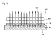
図1は本発明の一実施形態による高吸水性樹脂の切断装置の概略的な斜視図であり、図2は図1における本発明の一実施形態によるA−A′の断面を概略的に示す断面図であり、図3は図1における本発明の一実施形態によるB−B′の断面を概略的に示す断面図であり、図4は図1における本発明の他の実施形態によるB−B′の断面を概略的に示す断面図である。 FIG. 1 is a schematic perspective view of a cutting device for a superabsorbent resin according to an embodiment of the present invention, and FIG. 2 schematically shows a cross section taken along line A-A 'according to the embodiment of the present invention in FIG. FIG. 3 is a cross-sectional view schematically showing a cross section of BB ′ according to an embodiment of the present invention in FIG. 1, and FIG. 4 is a cross-sectional view according to another embodiment of the present invention in FIG. It is sectional drawing which shows the cross section of B 'roughly.
これら図を参照すると、高吸水性樹脂の切断装置100は、支持台160上で移動する高吸水性樹脂150が投入される投入部110、投入部110に入ってきた高吸水性樹脂150を1次切断する第1カッター120、1次切断された樹脂を2次切断する第2カッター130、及び切断された樹脂を排出する排出部140を含む。
Referring to these drawings, the superabsorbent
支持台160は特に限定されないが、高吸水性樹脂150を移送させるために一つのコンベヤーベルトまたは二つ以上のコンベヤーベルトの組合せからなる。二つ以上のコンベヤーベルトの組合せからなる場合、その連結部位は第1カッター120に対応する部位及び/または第2カッター130に対応する部位であり得る。
The
第1カッター120は高吸水性樹脂150を進行方向に平行な方向に切断することができる。この場合、第1カッター120は、例えば、ローラ型カッターであり得る。具体的な例において、第1カッター120は多数の円形刃122を含み、多数の円形刃122を連結する中心軸121を含み得る。中心軸121が別途の駆動部(図示せず)に連結されて回転運動をし、このような回転運動によって円形刃122が回転しながら高吸水性樹脂150を1次切断することができる。
The
円形刃122の間の間隔は工程上所望するサイズに応じて多様に適用することができる。例えば、5mmないし100mmの範囲に間隔を設定することができるが、これに限定されない。5mm未満である場合は円形刃122の間隔が狭すぎて切断過程で高吸水性樹脂150がつかえる現象が発生し得、100mm超過の場合は所望する切断効果が得られにくいという問題がある。
The interval between the
例示的な実施例において、円形刃122の終端は鋸歯形状で形成され得る。この場合、鋸歯は円形刃122と同じ平面上に形成されることもできるが、前記平面からずれて形成されることもできる。鋸歯が円形刃122と同じ平面からずれて形成される場合、隣接する二つの鋸歯は互いに異なる方向にずれていることもできる。
In an exemplary embodiment, the end of the
高吸水性樹脂150を挟んで、円形刃122に対応する位置で円形刃122が一部陥入するように溝161が形成され得る。この場合、高吸水性樹脂150が一部切断されないことにより発生する不良を防止することができ、より確実な切断効果を有することができる。
The
他の一つの例において、高吸水性樹脂150を挟んで、円形刃122に対応する位置で円形刃122に噛み合う補助刃(図示せず)が形成されていることもできる。この場合、円形刃122と補助刃がはさみのような方法で高吸水性樹脂150を切断することができる。
In another example, an auxiliary blade (not shown) that meshes with the
第2カッター130は高吸水性樹脂150を進行方向の垂直方向に切断することができる。この場合、第2カッター130は、直線往復運動する刃を含み得る。例えば、第2カッター130は上下直線に往復運動することにより、第1カッター120で1次切断した高吸水性樹脂150を2次切断することができる。
The
高吸水性樹脂150を挟んで、第2カッター130に対応する位置で刃が一部陥入するように溝162が形成され得る。この場合、高吸水性樹脂150が一部切断されないことにより発生する不良を防止することができ、より確実な切断効果を有することができる。
The
他の一つの例において、高吸水性樹脂150を挟んで、第2カッター130に対応する位置で第2カッター130の刃に噛み合う補助刃163が形成されていることもできる。この場合、第2カッター130の刃と補助刃163がはさみのような方法で高吸水性樹脂150を切断することができる。
In another example, an
2次切断間隔は、工程上所望するサイズに応じて多様に適用することができる。例えば、5mmないし100mmの範囲に間隔を設定することができるが、これに限定されない。5mm未満である場合は切断間隔が狭すぎるため、切断が円滑ではない場合もあり得、100mm超過である場合は所望する切断効果が得られにくいという問題がある。 The secondary cutting interval can be variously applied depending on the size desired in the process. For example, the interval can be set in a range of 5 mm to 100 mm, but is not limited thereto. If it is less than 5 mm, the cutting interval is too narrow, so that the cutting may not be smooth, and if it is more than 100 mm, the desired cutting effect is difficult to obtain.
排出部140の場合は図1の場合と同様に、支持台160が延長されていることができる。しかし、これに限定されず、別途の支持台160なしで切断された高吸水性樹脂150が落下して収納されるようにすることもできる。
In the case of the
高吸水性樹脂の製造方法Method for producing superabsorbent resin
図1ないし図4を参照して本発明の一実施形態による高吸水性樹脂の製造方法について説明する。 With reference to FIG. 1 thru | or FIG. 4, the manufacturing method of the super absorbent polymer by one Embodiment of this invention is demonstrated.
高吸水性樹脂の製造方法は、高吸水性樹脂を重合する段階、前記説明した高吸水性樹脂の切断装置100の投入部110に高吸水性樹脂150を投入する段階、第1カッター120及び第2カッター130で高吸水性樹脂150を切断する段階、及び切断された高吸水性樹脂150を排出する段階を含む。
The method for producing the superabsorbent resin includes the steps of polymerizing the superabsorbent resin, the step of introducing the
高吸水性樹脂を重合する段階は特に限定されないが、モノマー組成物を重合器に注入して重合することができる。この場合、高吸水性樹脂を形成するためにベルト上に前記モノマー組成物を注入して重合することができるが、これに限定されない。 The step of polymerizing the superabsorbent resin is not particularly limited, but the monomer composition can be injected into the polymerization vessel for polymerization. In this case, in order to form a highly water-absorbent resin, the monomer composition can be injected onto the belt for polymerization, but the present invention is not limited thereto.
モノマー組成物に含まれるモノマーとして水溶性エチレン系不飽和単量体は高吸水性樹脂の製造に一般的に使用される単量体であれば、いかなるものでも限定されず、使用することができる。モノマーは大きく陰イオン性単量体とその塩、非イオン性親水性含有単量体、及びアミノ基含有不飽和単量体及びその4級化物からなる群より選ばれる一つ以上を使用することができる。 As the monomer contained in the monomer composition, the water-soluble ethylenically unsaturated monomer is not limited as long as it is a monomer generally used in the production of a superabsorbent resin, and can be used. . The monomer is largely one or more selected from the group consisting of an anionic monomer and a salt thereof, a nonionic hydrophilic-containing monomer, an amino group-containing unsaturated monomer and a quaternized product thereof. Can do.
例示的な実施例で、アクリル酸、メタアクリル酸、無水マレイン酸、フマル酸、クロトン酸、イタコン酸、2−アクリロイルエタンスルホン酸、2−メタクリロイルエタンスルホン酸、2−(メタ)アクリロイルプロパンスルホン酸及び2−(メタ)アクリルアミド−2−メチルプロパンスルホン酸からなる群より選ばれる一つ以上の陰イオン性単量体またはその塩;(メタ)アクリルアミド、N−置換(メタ)アクリレート、2−ヒドロキシエチル(メタ)アクリレート、2−ヒドロキシプロピル(メタ)アクリレート、メトキシポリエチレングリコール(メタ)アクリレート及びポリエチレングリコール(メタ)アクリレートからなる群より選ばれる一つ以上の非イオン性親水性含有単量体;または(N,N)−ジメチルアミノエチル(メタ)アクリレート及び(N,N)−ジメチルアミノプロピル(メタ)アクリルアミドからなる群より選ばれる一つ以上のアミノ基含有不飽和単量体またはその4級化物などを含み得る。 Illustrative examples include acrylic acid, methacrylic acid, maleic anhydride, fumaric acid, crotonic acid, itaconic acid, 2-acryloylethanesulfonic acid, 2-methacryloylethanesulfonic acid, 2- (meth) acryloylpropanesulfonic acid. And one or more anionic monomers selected from the group consisting of 2- (meth) acrylamide-2-methylpropanesulfonic acid or a salt thereof; (meth) acrylamide, N-substituted (meth) acrylate, 2-hydroxy One or more nonionic hydrophilic-containing monomers selected from the group consisting of ethyl (meth) acrylate, 2-hydroxypropyl (meth) acrylate, methoxypolyethylene glycol (meth) acrylate and polyethylene glycol (meth) acrylate; or (N, N) -dimethylaminoethyl ( Motor) acrylate and (N, N) -, and the like dimethylaminopropyl (meth) one or more amino group-containing unsaturated monomer or its quaternary compound selected from the group consisting of acrylamide.
モノマー組成物のうち水溶性エチレン系不飽和単量体の濃度は、重合時間及び反応条件(モノマー組成物の供給速度、熱及び/または光の照射時間、照射範囲、及び照射強度、ベルトの幅、長さ及び移動速度など)を考慮して適切に選択して使用することができるが、例示的な実施例において、40ないし60重量%の範囲であり得る。この場合、モノマーの溶解度及び経済的な面において効率的であり得る。 The concentration of the water-soluble ethylenically unsaturated monomer in the monomer composition depends on the polymerization time and reaction conditions (monomer composition supply rate, heat and / or light irradiation time, irradiation range, irradiation intensity, belt width). , Length and moving speed, etc.) can be selected and used, but in the exemplary embodiment, it can be in the range of 40 to 60% by weight. This can be efficient in terms of monomer solubility and economics.
モノマー組成物は光重合開始剤、熱重合開始剤及び架橋剤からなる群より選ばれる一つ以上の添加剤をさらに含み得る。重合開始剤は工程過程で熱重合、光重合、または熱重合及び光重合を選択するかどうかによってその種類を適切に選択して使用することができる。 The monomer composition may further include one or more additives selected from the group consisting of a photopolymerization initiator, a thermal polymerization initiator, and a crosslinking agent. The polymerization initiator can be used by appropriately selecting the type depending on whether thermal polymerization, photopolymerization, or thermal polymerization and photopolymerization is selected in the process.
光重合開始剤は特に制限されないが、例えば、ジエトキシアセトフェノン、2−ヒドロキシ−2−メチル−1−フェニルプロパン−1−オン、4−(2−ヒドロキシエトキシ)フェニル−(2−ヒドロキシ)−2−プロピルケトン、1−ヒドロキシシクロヘキシルフェニルケトンなどのアセトフェノン誘導体;ベンゾインメチルエーテル、ベンゾインエチルエーテル、ベンゾインイソプロピルエーテル、ベンゾインイソブチルエーテルなどのベンゾインアルキルエーテル類化合物;o−ベンゾイル安息香酸メチル、4−フェニルベンゾフェノン、4−ベンゾイル−4′−メチル−ジフェニル硫化物、(4−ベンゾイルベンジル)トリメチルアンモニウム塩化物などのベンゾフェノン誘導体;チオキサントン(thioxanthone)系統化合物;ビス(2,4,6−トリメチルベンゾイル)−フェニルホスフィンオキサイド、ジフェニル(2,4,6−トリメチルベンゾイル)−ホスフィンオキシドなどのアシルホスフィンオキシド誘導体;または2−ヒドロキシメチルプロピオニトリル、2、2′−(アゾビス(2−メチル−N−(1,1′−ビス(ヒドロキシメチル)−2−ヒドロキシエチル)プロピオンアミド)などのアゾ系化合物などを1種または2種以上混合して使用することができるが、これらに限定されない。 The photopolymerization initiator is not particularly limited. For example, diethoxyacetophenone, 2-hydroxy-2-methyl-1-phenylpropan-1-one, 4- (2-hydroxyethoxy) phenyl- (2-hydroxy) -2 Acetophenone derivatives such as propyl ketone and 1-hydroxycyclohexyl phenyl ketone; benzoin alkyl ether compounds such as benzoin methyl ether, benzoin ethyl ether, benzoin isopropyl ether and benzoin isobutyl ether; o-benzoyl methyl benzoate, 4-phenylbenzophenone, Benzophenone derivatives such as 4-benzoyl-4'-methyl-diphenyl sulfide, (4-benzoylbenzyl) trimethylammonium chloride; thioxanthone line Compound; Acylphosphine oxide derivatives such as bis (2,4,6-trimethylbenzoyl) -phenylphosphine oxide, diphenyl (2,4,6-trimethylbenzoyl) -phosphine oxide; or 2-hydroxymethylpropionitrile, 2 Azo compounds such as 2 ′-(azobis (2-methyl-N- (1,1′-bis (hydroxymethyl) -2-hydroxyethyl) propionamide), etc. However, it is not limited to these.
熱重合開始剤は特に制限されないが、例えば、アゾ系(azo)開始剤、過酸化物系開始剤、レドックス(redox)系統開始剤または有機ハロゲン化物開始剤などを1種または2種以上混合して使用することができる。また、前記熱重合開始剤のうち過硫酸ナトリウム(Sodium persulfate、Na2S2O8)または過硫酸カリウム(Potassium persulfate、K2S2O8)が挙げられるが、これらに限定されない。 The thermal polymerization initiator is not particularly limited. For example, one or more azo initiators, peroxide initiators, redox initiators or organic halide initiators are mixed. Can be used. Examples of the thermal polymerization initiator include sodium persulfate (Sodium persulfate, Na 2 S 2 O 8 ) or potassium persulfate (Potassium persulfate, K 2 S 2 O 8 ), but are not limited thereto.
モノマー組成物で、光重合開始剤及び熱重合開始剤は重合開始効果を示すことができれば、その含有量は選択して使用することができる。例示的な実施例において、光重合開始剤は単量体100重量部に対し、0.005ないし0.1重量部の範囲で含まれ得、熱重合開始剤は単量体100重量部に対し、0.01ないし0.5重量部の範囲で含まれ得るが、これに限定されない。 In the monomer composition, if the photopolymerization initiator and the thermal polymerization initiator can exhibit a polymerization initiation effect, their contents can be selected and used. In an exemplary embodiment, the photopolymerization initiator may be included in the range of 0.005 to 0.1 parts by weight with respect to 100 parts by weight of the monomer, and the thermal polymerization initiator is based on 100 parts by weight of the monomer. However, it is not limited to 0.01 to 0.5 parts by weight.
架橋剤は単量体の置換基と反応できる官能基及びエチレン性不飽和基をそれぞれ一つ以上含む架橋剤、または単量体の置換基及び/または前記単量体を加水分解して形成された置換基と反応できる官能基を2以上含む架橋剤を使用することができる。 The cross-linking agent is a cross-linking agent containing at least one functional group capable of reacting with a monomer substituent and one or more ethylenically unsaturated groups, or formed by hydrolyzing the monomer substituent and / or the monomer. A crosslinking agent containing two or more functional groups capable of reacting with the substituents can be used.
例示的な実施例において、架橋剤は炭素数8ないし12のビスアクリルアミド、炭素数8ないし12のビスメタアクリルアミド、炭素数2ないし10のポリオールのポリ(メタ)アクリレートまたは炭素数2ないし10のポリオールのポリ(メタ)アリルエーテルなどが挙げられ、より具体的な例としては、N,N′−メチレンビス(メタ)アクリレート、エチレンオキシ(メタ)アクリレート、ポリエチレンオキシ(メタ)アクリレート、プロピレンオキシ(メタ)アクリレート、グリセリンジアクリレート、グリセリントリアクリレート、トリメチロールトリアクリレート、トリアリルアミン、トリアリルシアヌレート、トリアリルイソシアネート、ポリエチレングリコール、ジエチレングリコール、プロピレングリコールまたはこれらの2種以上の混合物が挙げられるが、これに限定されない。 In exemplary embodiments, the cross-linking agent is a bisacrylamide having 8 to 12 carbons, bismethacrylamide having 8 to 12 carbons, a poly (meth) acrylate of a polyol having 2 to 10 carbons or a polyol having 2 to 10 carbons. More specific examples include N, N'-methylenebis (meth) acrylate, ethyleneoxy (meth) acrylate, polyethyleneoxy (meth) acrylate, and propyleneoxy (meth). Acrylate, glycerin diacrylate, glycerin triacrylate, trimethylol triacrylate, triallylamine, triallyl cyanurate, triallyl isocyanate, polyethylene glycol, diethylene glycol, propylene glycol or these Mixtures of two or more include, but are not limited thereto.
モノマー組成物で、架橋剤は架橋効果を示すことができれば、その含有量は選択して使用することができる。例示的な実施例において、架橋剤は単量体100重量部に対し、0.01ないし0.5重量部の範囲で含まれ得るが、これに限定されない。 In the monomer composition, if the crosslinking agent can exhibit a crosslinking effect, its content can be selected and used. In an exemplary embodiment, the crosslinking agent may be included in the range of 0.01 to 0.5 parts by weight with respect to 100 parts by weight of the monomer, but is not limited thereto.
重合が完了した高吸水性樹脂は、切断装置100の投入部110に投入され、第1カッター120及び第2カッター130で高吸水性樹脂150が切断される段階を経る。
The superabsorbent resin that has been polymerized is put into the
この場合、第1カッター120は高吸水性樹脂150を進行方向に平行な方向(長さ方向)に1次切断することができ、第2カッター130は1次切断された高吸水性樹脂150を進行方向に垂直な方向(幅方向)に2次切断することができる。または、第1カッター120が幅方向に1次切断し、第2カッター130が長さ方向に2次切断することもできる。
In this case, the
切断が完了した高吸水性樹脂150は排出部140に排出され、その後粉砕、乾燥及び乾燥された重合体をさらに粉砕する段階をさらに含み得る。場合によっては粉砕工程の前に、仮乾燥段階をさらに含み、粉砕工程でかたまることなどを防止することができる。
The
粉砕方法は特に限定されないが、例えば、ゴム状弾性体を切断、押出する装置を利用することができる。例示的な実施例において、カッター型切断機、チョッパ型切断機、ニーダー型切断機、振動式粉砕機、衝撃式粉砕機、摩擦型粉砕機などが挙げられるが、これに限定されない。 The pulverization method is not particularly limited. For example, an apparatus for cutting and extruding a rubber-like elastic body can be used. Examples include, but are not limited to, cutter cutters, chopper cutters, kneader cutters, vibration pulverizers, impact pulverizers, friction pulverizers, and the like.
乾燥方法としては通常乾燥器と加熱炉を利用することができる。例示的な実施例において、熱風乾燥器、流動層乾燥器、気流乾燥器、赤外線乾燥器、誘電加熱乾燥器などが挙げられるが、これに限定されない。乾燥温度は特に制限されないが、熱劣化を防止して効率的に乾燥するため、100ないし200℃の範囲であり得る。 As a drying method, a normal dryer and a heating furnace can be used. Exemplary embodiments include, but are not limited to, hot air dryers, fluidized bed dryers, airflow dryers, infrared dryers, dielectric heat dryers, and the like. The drying temperature is not particularly limited, but may be in the range of 100 to 200 ° C. in order to prevent heat deterioration and efficiently dry.
以上添付する図面を参照して本発明の実施例について説明したが、本発明は前記実施例に限定されず、互いに異なる多様な形態で製造され得、本発明が属する技術分野における通常の知識を有する者は、本発明の技術的な思想や必須の特徴を変更しない範囲で他の具体的な形態で実施され得るということを理解することができる。したがって、上記実施例はすべての面で例示的なものであり、限定的なものではないと理解しなければならない。 Although the embodiments of the present invention have been described with reference to the accompanying drawings, the present invention is not limited to the above-described embodiments, and can be manufactured in various different forms, and has ordinary knowledge in the technical field to which the present invention belongs. Those who have can understand that the present invention can be implemented in other specific forms without changing the technical idea and essential features of the present invention. Therefore, it should be understood that the above embodiments are illustrative in all aspects and not limiting.
Claims (11)
前記高吸水性樹脂を1次切断する第1カッターと、
前記高吸水性樹脂を2次切断する第2カッターと、
前記切断された高吸水性樹脂が排出される排出部を含む高吸水性樹脂の切断装置。 A charging portion into which a superabsorbent resin is charged;
A first cutter for primarily cutting the superabsorbent resin;
A second cutter for secondary cutting the superabsorbent resin;
A superabsorbent resin cutting device including a discharge part from which the cut superabsorbent resin is discharged.
前記高吸水性樹脂の進行方向に対応して回転する請求項4に記載の高吸水性樹脂の切断装置。 The roller cutter includes a number of blades,
The cutting device for a superabsorbent resin according to claim 4, wherein the superabsorbent resin rotates in accordance with a traveling direction of the superabsorbent resin.
前記多数の刃に対応して形成される補助刃または溝をさらに含む請求項5に記載の高吸水性樹脂の切断装置。 Sandwiching the superabsorbent resin,
The superabsorbent resin cutting device according to claim 5, further comprising auxiliary blades or grooves formed corresponding to the plurality of blades.
前記第2カッターの刃に対応して形成される補助刃または溝をさらに含む請求項8に記載の高吸水性樹脂の切断装置。 Sandwiching the superabsorbent resin,
The superabsorbent resin cutting device according to claim 8, further comprising an auxiliary blade or a groove formed corresponding to the blade of the second cutter.
請求項1ないし請求項9のうちいずれか一項に記載の高吸水性樹脂の切断装置の投入部に前記高吸水性樹脂を投入する段階と、
第1カッター及び第2カッターで前記高吸水性樹脂を切断する段階と、
切断された高吸水性樹脂を排出する段階を含む高吸水性樹脂の製造方法。 Polymerizing a superabsorbent resin;
Charging the superabsorbent resin into the input portion of the cutting device for the superabsorbent resin according to any one of claims 1 to 9,
Cutting the superabsorbent resin with a first cutter and a second cutter;
A method for producing a superabsorbent resin comprising discharging the cut superabsorbent resin.
前記乾燥された重合体を粉砕する段階をさらに含む請求項10に記載の高吸水性樹脂の製造方法。
Drying the polymer discharged through the discharge section;
The method for producing a superabsorbent resin according to claim 10, further comprising pulverizing the dried polymer.
Applications Claiming Priority (3)
| Application Number | Priority Date | Filing Date | Title |
|---|---|---|---|
| KR1020140011500A KR20150090620A (en) | 2014-01-29 | 2014-01-29 | Apparatus for cutting super absorbent polymer and method for preparing super absorbent polymer using the same |
| KR10-2014-0011500 | 2014-01-29 | ||
| PCT/KR2015/000952 WO2015115821A1 (en) | 2014-01-29 | 2015-01-29 | Apparatus for cutting super absorbent polymer and method for preparing super absorbent polymer using same |
Publications (1)
| Publication Number | Publication Date |
|---|---|
| JP2017505722A true JP2017505722A (en) | 2017-02-23 |
Family
ID=53757340
Family Applications (1)
| Application Number | Title | Priority Date | Filing Date |
|---|---|---|---|
| JP2016546828A Pending JP2017505722A (en) | 2014-01-29 | 2015-01-29 | Superabsorbent resin cutting device and method for producing superabsorbent resin using the same |
Country Status (7)
| Country | Link |
|---|---|
| US (1) | US20170165861A1 (en) |
| EP (1) | EP3103602A1 (en) |
| JP (1) | JP2017505722A (en) |
| KR (1) | KR20150090620A (en) |
| BR (1) | BR112016016297A2 (en) |
| TW (1) | TWI571368B (en) |
| WO (1) | WO2015115821A1 (en) |
Families Citing this family (8)
| Publication number | Priority date | Publication date | Assignee | Title |
|---|---|---|---|---|
| FR3056136A1 (en) * | 2016-09-20 | 2018-03-23 | Compagnie Plastic Omnium | SYSTEM FOR CUTTING A FABRIC OF REINFORCING FIBERS FOR THE MANUFACTURE OF SHEETS OF REINFORCED PLASTIC MATERIAL |
| CN107127804A (en) * | 2017-07-04 | 2017-09-05 | 贵港市益福美农资有限公司 | A kind of cutting machine for producing chemical fibre |
| CN107696147A (en) * | 2017-11-23 | 2018-02-16 | 海盐华港印刷有限公司 | A kind of trade mark cutting means |
| CN111283782A (en) * | 2020-03-19 | 2020-06-16 | 江西铜博科技有限公司 | Copper foil guillootine convenient to handle waste material |
| CN111604989B (en) * | 2020-06-04 | 2021-11-02 | 福建省信明橡塑有限公司 | Quick rubber cutting machine for processing rubber functional material products |
| CN114474209A (en) * | 2021-04-21 | 2022-05-13 | 陈威 | Silica gel sheet processing is with accurate location cutting device |
| CN114030020A (en) * | 2021-09-24 | 2022-02-11 | 福建升隆食品有限公司 | Waist flower cutting machine with safety protection mechanism |
| CN115069375B (en) * | 2022-06-20 | 2023-10-13 | 大同大源药业有限责任公司 | High-speed traditional chinese medicine rubbing crusher |
Family Cites Families (8)
| Publication number | Priority date | Publication date | Assignee | Title |
|---|---|---|---|---|
| JPS56161408A (en) | 1980-05-19 | 1981-12-11 | Kao Corp | Production of water-absorbing resin |
| JPS57158209A (en) | 1981-03-25 | 1982-09-30 | Kao Corp | Production of bead-form highly water-absorbing polymer |
| JPS57198714A (en) | 1981-05-29 | 1982-12-06 | Sumitomo Chem Co Ltd | Production of hydrogel |
| KR100872814B1 (en) * | 2007-07-11 | 2008-12-09 | 신덕하 | Manufacturing method of the removal tape for prism-lgp in lcd display device |
| JP5021541B2 (en) * | 2008-03-28 | 2012-09-12 | 王子ネピア株式会社 | Manufacturing method of absorbent body, absorbent body and disposable diaper equipped with absorbent body |
| KR101317815B1 (en) * | 2010-06-16 | 2013-10-15 | 주식회사 엘지화학 | Preparation method of super absorbent polymer |
| KR20120047035A (en) * | 2010-11-03 | 2012-05-11 | 주식회사 엘지화학 | Preparation method for super absorbent polymer capable of suppressing powder-creation |
| KR101058149B1 (en) * | 2011-04-15 | 2011-08-25 | 황복남 | Slitting apparatus with inserting means for supporting and guiding steel plate |
-
2014
- 2014-01-29 KR KR1020140011500A patent/KR20150090620A/en not_active Application Discontinuation
-
2015
- 2015-01-29 US US15/115,418 patent/US20170165861A1/en not_active Abandoned
- 2015-01-29 JP JP2016546828A patent/JP2017505722A/en active Pending
- 2015-01-29 TW TW104103016A patent/TWI571368B/en not_active IP Right Cessation
- 2015-01-29 EP EP15742759.2A patent/EP3103602A1/en not_active Withdrawn
- 2015-01-29 BR BR112016016297A patent/BR112016016297A2/en not_active IP Right Cessation
- 2015-01-29 WO PCT/KR2015/000952 patent/WO2015115821A1/en active Application Filing
Also Published As
| Publication number | Publication date |
|---|---|
| KR20150090620A (en) | 2015-08-06 |
| US20170165861A1 (en) | 2017-06-15 |
| TW201544277A (en) | 2015-12-01 |
| BR112016016297A2 (en) | 2017-08-08 |
| TWI571368B (en) | 2017-02-21 |
| EP3103602A1 (en) | 2016-12-14 |
| WO2015115821A1 (en) | 2015-08-06 |
Similar Documents
| Publication | Publication Date | Title |
|---|---|---|
| JP2017505722A (en) | Superabsorbent resin cutting device and method for producing superabsorbent resin using the same | |
| CN104144973B (en) | Prepare the method for super absorbent polymer, and the super absorbent polymer prepared by the method | |
| KR101393681B1 (en) | Preparation method of super absorbent polymer | |
| JP2017501295A (en) | Method for producing superabsorbent resin | |
| US10894867B2 (en) | Manufacturing method of super absorbent polymer | |
| KR101126678B1 (en) | Polymerization reactores for the preparation of super absorbent polymer and preparation method thereof using the same | |
| JP2017505833A (en) | Superabsorbent resin cutting device and method for producing superabsorbent resin using the same | |
| KR101648138B1 (en) | Polymerization reactores for preparation of super absorbent polymer and method for preparing of super absorbent polymer using the same | |
| JP2016540093A (en) | High water-absorbing resin manufacturing apparatus and method for manufacturing high water-absorbing resin using the same | |
| KR101317815B1 (en) | Preparation method of super absorbent polymer | |
| JP2017503058A (en) | Super absorbent polymer manufacturing method | |
| TWI547512B (en) | Apparatus of preparing super absorbent polymer and preparation method of super absorbent polymer using the same | |
| KR102186939B1 (en) | Method for preparing super absorbent polymer | |
| KR102079337B1 (en) | Shredder for super adsorbent polymer and preparation method of super absorbent polymer using the same | |
| KR102213451B1 (en) | Super absorbent polymer and method for preparing the same | |
| KR20120047034A (en) | Preparation method for super absorbent polymer | |
| WO2015108350A1 (en) | Super absorbent resin cutting device and super absorbent resin manufacturing method using same | |
| KR101367362B1 (en) | Polymerization reactor and preparation method of super absorbent polymer | |
| KR102079338B1 (en) | Shredder for super adsorbent polymer and preparation method of super absorbent polymer using the same | |
| KR20120047036A (en) | Apparatus for preparing super absorbent polymer and preparation method of super absorbent polymer using the same | |
| TW201630944A (en) | Method for preparing super absorbent polymer | |
| KR20170052908A (en) | Method for preparing super absorbent polymer |