JP2017505512A - Battery pack having cell fixing device - Google Patents
Battery pack having cell fixing device Download PDFInfo
- Publication number
- JP2017505512A JP2017505512A JP2016539976A JP2016539976A JP2017505512A JP 2017505512 A JP2017505512 A JP 2017505512A JP 2016539976 A JP2016539976 A JP 2016539976A JP 2016539976 A JP2016539976 A JP 2016539976A JP 2017505512 A JP2017505512 A JP 2017505512A
- Authority
- JP
- Japan
- Prior art keywords
- pcb
- cell
- cells
- battery pack
- connection
- Prior art date
- Legal status (The legal status is an assumption and is not a legal conclusion. Google has not performed a legal analysis and makes no representation as to the accuracy of the status listed.)
- Pending
Links
Images


Classifications
-
- H—ELECTRICITY
- H01—ELECTRIC ELEMENTS
- H01M—PROCESSES OR MEANS, e.g. BATTERIES, FOR THE DIRECT CONVERSION OF CHEMICAL ENERGY INTO ELECTRICAL ENERGY
- H01M10/00—Secondary cells; Manufacture thereof
- H01M10/42—Methods or arrangements for servicing or maintenance of secondary cells or secondary half-cells
- H01M10/425—Structural combination with electronic components, e.g. electronic circuits integrated to the outside of the casing
- H01M10/4257—Smart batteries, e.g. electronic circuits inside the housing of the cells or batteries
-
- H—ELECTRICITY
- H01—ELECTRIC ELEMENTS
- H01M—PROCESSES OR MEANS, e.g. BATTERIES, FOR THE DIRECT CONVERSION OF CHEMICAL ENERGY INTO ELECTRICAL ENERGY
- H01M10/00—Secondary cells; Manufacture thereof
- H01M10/42—Methods or arrangements for servicing or maintenance of secondary cells or secondary half-cells
- H01M10/425—Structural combination with electronic components, e.g. electronic circuits integrated to the outside of the casing
-
- H—ELECTRICITY
- H01—ELECTRIC ELEMENTS
- H01M—PROCESSES OR MEANS, e.g. BATTERIES, FOR THE DIRECT CONVERSION OF CHEMICAL ENERGY INTO ELECTRICAL ENERGY
- H01M10/00—Secondary cells; Manufacture thereof
- H01M10/04—Construction or manufacture in general
- H01M10/0422—Cells or battery with cylindrical casing
-
- H—ELECTRICITY
- H01—ELECTRIC ELEMENTS
- H01M—PROCESSES OR MEANS, e.g. BATTERIES, FOR THE DIRECT CONVERSION OF CHEMICAL ENERGY INTO ELECTRICAL ENERGY
- H01M10/00—Secondary cells; Manufacture thereof
- H01M10/05—Accumulators with non-aqueous electrolyte
- H01M10/052—Li-accumulators
- H01M10/0525—Rocking-chair batteries, i.e. batteries with lithium insertion or intercalation in both electrodes; Lithium-ion batteries
-
- H—ELECTRICITY
- H01—ELECTRIC ELEMENTS
- H01M—PROCESSES OR MEANS, e.g. BATTERIES, FOR THE DIRECT CONVERSION OF CHEMICAL ENERGY INTO ELECTRICAL ENERGY
- H01M10/00—Secondary cells; Manufacture thereof
- H01M10/05—Accumulators with non-aqueous electrolyte
- H01M10/054—Accumulators with insertion or intercalation of metals other than lithium, e.g. with magnesium or aluminium
-
- H—ELECTRICITY
- H01—ELECTRIC ELEMENTS
- H01M—PROCESSES OR MEANS, e.g. BATTERIES, FOR THE DIRECT CONVERSION OF CHEMICAL ENERGY INTO ELECTRICAL ENERGY
- H01M10/00—Secondary cells; Manufacture thereof
- H01M10/42—Methods or arrangements for servicing or maintenance of secondary cells or secondary half-cells
- H01M10/48—Accumulators combined with arrangements for measuring, testing or indicating the condition of cells, e.g. the level or density of the electrolyte
- H01M10/482—Accumulators combined with arrangements for measuring, testing or indicating the condition of cells, e.g. the level or density of the electrolyte for several batteries or cells simultaneously or sequentially
-
- H—ELECTRICITY
- H01—ELECTRIC ELEMENTS
- H01M—PROCESSES OR MEANS, e.g. BATTERIES, FOR THE DIRECT CONVERSION OF CHEMICAL ENERGY INTO ELECTRICAL ENERGY
- H01M50/00—Constructional details or processes of manufacture of the non-active parts of electrochemical cells other than fuel cells, e.g. hybrid cells
- H01M50/20—Mountings; Secondary casings or frames; Racks, modules or packs; Suspension devices; Shock absorbers; Transport or carrying devices; Holders
- H01M50/204—Racks, modules or packs for multiple batteries or multiple cells
- H01M50/207—Racks, modules or packs for multiple batteries or multiple cells characterised by their shape
- H01M50/213—Racks, modules or packs for multiple batteries or multiple cells characterised by their shape adapted for cells having curved cross-section, e.g. round or elliptic
-
- H—ELECTRICITY
- H01—ELECTRIC ELEMENTS
- H01M—PROCESSES OR MEANS, e.g. BATTERIES, FOR THE DIRECT CONVERSION OF CHEMICAL ENERGY INTO ELECTRICAL ENERGY
- H01M50/00—Constructional details or processes of manufacture of the non-active parts of electrochemical cells other than fuel cells, e.g. hybrid cells
- H01M50/20—Mountings; Secondary casings or frames; Racks, modules or packs; Suspension devices; Shock absorbers; Transport or carrying devices; Holders
- H01M50/218—Mountings; Secondary casings or frames; Racks, modules or packs; Suspension devices; Shock absorbers; Transport or carrying devices; Holders characterised by the material
- H01M50/22—Mountings; Secondary casings or frames; Racks, modules or packs; Suspension devices; Shock absorbers; Transport or carrying devices; Holders characterised by the material of the casings or racks
- H01M50/227—Organic material
-
- H—ELECTRICITY
- H01—ELECTRIC ELEMENTS
- H01M—PROCESSES OR MEANS, e.g. BATTERIES, FOR THE DIRECT CONVERSION OF CHEMICAL ENERGY INTO ELECTRICAL ENERGY
- H01M50/00—Constructional details or processes of manufacture of the non-active parts of electrochemical cells other than fuel cells, e.g. hybrid cells
- H01M50/20—Mountings; Secondary casings or frames; Racks, modules or packs; Suspension devices; Shock absorbers; Transport or carrying devices; Holders
- H01M50/262—Mountings; Secondary casings or frames; Racks, modules or packs; Suspension devices; Shock absorbers; Transport or carrying devices; Holders with fastening means, e.g. locks
-
- H—ELECTRICITY
- H01—ELECTRIC ELEMENTS
- H01M—PROCESSES OR MEANS, e.g. BATTERIES, FOR THE DIRECT CONVERSION OF CHEMICAL ENERGY INTO ELECTRICAL ENERGY
- H01M50/00—Constructional details or processes of manufacture of the non-active parts of electrochemical cells other than fuel cells, e.g. hybrid cells
- H01M50/20—Mountings; Secondary casings or frames; Racks, modules or packs; Suspension devices; Shock absorbers; Transport or carrying devices; Holders
- H01M50/284—Mountings; Secondary casings or frames; Racks, modules or packs; Suspension devices; Shock absorbers; Transport or carrying devices; Holders with incorporated circuit boards, e.g. printed circuit boards [PCB]
-
- H—ELECTRICITY
- H01—ELECTRIC ELEMENTS
- H01M—PROCESSES OR MEANS, e.g. BATTERIES, FOR THE DIRECT CONVERSION OF CHEMICAL ENERGY INTO ELECTRICAL ENERGY
- H01M50/00—Constructional details or processes of manufacture of the non-active parts of electrochemical cells other than fuel cells, e.g. hybrid cells
- H01M50/20—Mountings; Secondary casings or frames; Racks, modules or packs; Suspension devices; Shock absorbers; Transport or carrying devices; Holders
- H01M50/296—Mountings; Secondary casings or frames; Racks, modules or packs; Suspension devices; Shock absorbers; Transport or carrying devices; Holders characterised by terminals of battery packs
-
- H—ELECTRICITY
- H01—ELECTRIC ELEMENTS
- H01M—PROCESSES OR MEANS, e.g. BATTERIES, FOR THE DIRECT CONVERSION OF CHEMICAL ENERGY INTO ELECTRICAL ENERGY
- H01M50/00—Constructional details or processes of manufacture of the non-active parts of electrochemical cells other than fuel cells, e.g. hybrid cells
- H01M50/50—Current conducting connections for cells or batteries
- H01M50/502—Interconnectors for connecting terminals of adjacent batteries; Interconnectors for connecting cells outside a battery casing
- H01M50/519—Interconnectors for connecting terminals of adjacent batteries; Interconnectors for connecting cells outside a battery casing comprising printed circuit boards [PCB]
-
- H—ELECTRICITY
- H02—GENERATION; CONVERSION OR DISTRIBUTION OF ELECTRIC POWER
- H02K—DYNAMO-ELECTRIC MACHINES
- H02K11/00—Structural association of dynamo-electric machines with electric components or with devices for shielding, monitoring or protection
- H02K11/0094—Structural association with other electrical or electronic devices
-
- H—ELECTRICITY
- H01—ELECTRIC ELEMENTS
- H01M—PROCESSES OR MEANS, e.g. BATTERIES, FOR THE DIRECT CONVERSION OF CHEMICAL ENERGY INTO ELECTRICAL ENERGY
- H01M2220/00—Batteries for particular applications
- H01M2220/30—Batteries in portable systems, e.g. mobile phone, laptop
-
- Y—GENERAL TAGGING OF NEW TECHNOLOGICAL DEVELOPMENTS; GENERAL TAGGING OF CROSS-SECTIONAL TECHNOLOGIES SPANNING OVER SEVERAL SECTIONS OF THE IPC; TECHNICAL SUBJECTS COVERED BY FORMER USPC CROSS-REFERENCE ART COLLECTIONS [XRACs] AND DIGESTS
- Y02—TECHNOLOGIES OR APPLICATIONS FOR MITIGATION OR ADAPTATION AGAINST CLIMATE CHANGE
- Y02E—REDUCTION OF GREENHOUSE GAS [GHG] EMISSIONS, RELATED TO ENERGY GENERATION, TRANSMISSION OR DISTRIBUTION
- Y02E60/00—Enabling technologies; Technologies with a potential or indirect contribution to GHG emissions mitigation
- Y02E60/10—Energy storage using batteries
-
- Y—GENERAL TAGGING OF NEW TECHNOLOGICAL DEVELOPMENTS; GENERAL TAGGING OF CROSS-SECTIONAL TECHNOLOGIES SPANNING OVER SEVERAL SECTIONS OF THE IPC; TECHNICAL SUBJECTS COVERED BY FORMER USPC CROSS-REFERENCE ART COLLECTIONS [XRACs] AND DIGESTS
- Y02—TECHNOLOGIES OR APPLICATIONS FOR MITIGATION OR ADAPTATION AGAINST CLIMATE CHANGE
- Y02P—CLIMATE CHANGE MITIGATION TECHNOLOGIES IN THE PRODUCTION OR PROCESSING OF GOODS
- Y02P70/00—Climate change mitigation technologies in the production process for final industrial or consumer products
- Y02P70/50—Manufacturing or production processes characterised by the final manufactured product
Abstract
電池パックは、セルのうちのそれぞれのセルの長手方向センターラインが、第一方向において、実質的に相互に平行な状態においてアライメントされるように、実質的に相互に隣接した状態において配列された複数のセルと、ハウジング内においてセルを保持するべくセルのそれぞれと接触するように配設されたセル保持部分を含む物理的セル接続組立体と、グループのそれぞれと関連付けられたセルの電気的接続を促進するべくグループ内のセルのうちの少なくとも選択されたセルに接触するように配設された複数のセルコネクタを含む電気的セル接続組立体であって、セルコネクタのうちのそれぞれのセルコネクタの接触部分は、セルのうちの少なくとも二つのセルの電極を電気的に接続するように配設されている、電気的セル接続組立体と、印刷回路板(PCB)と電気的セル接続組立体との間の電気的通信に基づいてセルと関連付けられた電気的パラメータを監視するように構成されたPCBと、を含んでもよい。セル接続組立体の少なくとも一つのセルコネクタは、物理的セル接続組立体と係合する保持部分と、物理的セル接続組立体との関係におけるPCBの保持を促進するためにPCBに係合するべく該PCBのプレーンに対して実質的に垂直に延在している固定部分と、を含んでもよい。The battery packs were arranged substantially adjacent to each other such that the longitudinal centerlines of each of the cells are aligned in a first direction and substantially parallel to each other. A physical cell connection assembly including a plurality of cells and a cell holding portion disposed to contact each of the cells to hold the cell within the housing, and electrical connection of the cells associated with each of the groups An electrical cell connection assembly including a plurality of cell connectors arranged to contact at least selected cells of the cells in the group to promote the cell connector, each cell connector of the cell connectors The contact portion of the electrical cell connection assembly arranged to electrically connect electrodes of at least two of the cells. When a PCB configured to monitor an electrical parameter associated with the cells based on the electrical communication between the printed circuit board and (PCB) electrically cell connection assembly may include. At least one cell connector of the cell connection assembly is adapted to engage the PCB to facilitate retention of the PCB in relation to the physical cell connection assembly and a retaining portion that engages the physical cell connection assembly. And a fixed portion that extends substantially perpendicular to the plane of the PCB.
Description
例示用の実施形態は、一般に、電池パック技術に関し、且つ、更に詳しくは、セルコネクタを印刷回路板(printed circuit board:PCB)に接続すると共にセルパラメータを計測するための改善された技法を利用した電池パックに関する。 Exemplary embodiments generally relate to battery pack technology and, more particularly, utilize improved techniques for connecting cell connectors to a printed circuit board (PCB) and measuring cell parameters. Battery pack.
特性維持タスクは、一般に、対応する特定のタスクの実行のために構成された様々な工具及び/又は機械を使用して実行される。樹木の伐採、植物の刈り込み、くずの吹き飛ばし、及びこれらに類似したもののような特定のタスクは、通常、ハンドヘルド型の工具又は動力機械(power equipment)により、実行されている。ハンドヘルド型の動力機械は、しばしば、ガス又は電気モータによって動力供給され得る。電池によって電力供給される電動工具が登場するまでは、多くの場合に、ガスによって動力供給されるモータが、高度な移動性を所望するか又は必要としている操作者により、選好されてきた。従って、芝刈り機などの人間が後から歩いて付いて行く又はその上に跨るタイプの多くの屋外動力機械装置は、多くの場合に、ガスモータによって動力供給されており、その理由は、これらの屋外動力機械装置が、通常、相対的に大きな距離にわたる動作を必要としているからである。但し、電池技術の継続的な改善に起因して、電池によって電力供給される機器の安定性も改善されており、従って、このような装置が人気を博するようになっている。 A property maintenance task is typically performed using various tools and / or machines configured for the execution of the corresponding specific task. Certain tasks, such as tree cutting, plant trimming, litter blowing, and the like, are usually performed by handheld tools or power equipment. Handheld power machines can often be powered by gas or electric motors. Until the advent of power tools powered by batteries, in many cases motors powered by gas have been preferred by operators who desire or need a high degree of mobility. Therefore, many outdoor powered mechanical devices of the type that humans such as lawn mowers follow or straddle over are often powered by gas motors because of these reasons This is because outdoor power machinery usually requires operation over a relatively large distance. However, due to the continuous improvement of battery technology, the stability of the equipment powered by the battery has also improved, and thus such devices have become popular.
ハンドヘルド型の動力機械において利用される電池は、いくつかのケースにおいては、望ましい出力特性を実現するべく、直列及び/又は並列構成において一つに配列された複数の相対的に小さなセルの着脱自在且つ/又は充電式の組立体であってもよい。但し、電池パックを形成するべく、これらのセルが一つに配列される際には、セルが、時間に伴って変化する異なる特性を有する場合があり、且つ、その結果、セルの間のやり取りに対して影響が及び得ることを考慮しておくことが重要である。例えば、一つのセルの劣化又は障害が始まった場合に、その結果、その他のセルに影響が及ぶ場合がある。更には、一つ又は複数のセルが、一つ又は複数のセルの障害をもたらす圧力応力に曝露された場合に、その他のセルが、影響を受けると共に電池パック全体の損傷又は障害が生じる場合がある。従って、セルパラメータを計測することにより、セルの損傷をもたらし得る状況を検出することが有用であろう。 Batteries used in handheld power machines are, in some cases, removable of a plurality of relatively small cells arranged together in a series and / or parallel configuration to achieve the desired output characteristics. And / or a rechargeable assembly. However, when these cells are arranged together to form a battery pack, the cells may have different characteristics that change with time, and as a result, the exchange between the cells. It is important to take into account that this can have an impact on. For example, when deterioration or failure of one cell starts, the other cells may be affected as a result. In addition, when one or more cells are exposed to pressure stresses that cause one or more cell failures, other cells may be affected and damage or failure of the entire battery pack may occur. is there. Therefore, it would be useful to detect conditions that can cause cell damage by measuring cell parameters.
電池パックに対する損傷を回避するには、障害を防止するか又はその尤度を低減し得る設計特徴の利用を検討することが重要であろう。電池パックは、しばしば、複数の段階において組み立てられるという点を考慮した場合に、これらの段階において、いくつかのコンポーネントの溶接又ははんだ付けが発生し得ることを理解されたい。溶接又ははんだ付けが実行される際にコンポーネントが適切にアライメントされていない場合には、結果的に得られる結合部には、電池パックが動作の最中に振動又は衝撃を経験した際に、損傷又は障害が発生しやすくなろう。従って、損傷を軽減又は防止する設計特徴の提供との関係において、これらの溶接又ははんだ付けの結合部が、製造プロセスにおいて、改善された品質及び一貫性を有するように生成され得ることを保証することが有用であろう。又、設計それ自体が、セルパラメータの有用な計測を実施し得るようなものになっておれば、更に有用であろう。 To avoid damage to the battery pack, it may be important to consider the use of design features that can prevent or reduce the likelihood of failure. It should be understood that welding or soldering of several components may occur at these stages, given that battery packs are often assembled at multiple stages. If the components are not properly aligned when welding or soldering is performed, the resulting joint will be damaged if the battery pack experiences vibration or impact during operation. Or it will be more prone to failure. Thus, in the context of providing design features that reduce or prevent damage, ensure that these welded or soldered joints can be produced with improved quality and consistency in the manufacturing process. It would be useful. It would also be useful if the design itself was such that useful measurements of cell parameters could be performed.
いくつかの例示用の実施形態は、電気接続コンポーネントが二重の機能を提供するように構成された電池パックを提供し得る。この観点において、例えば、二重の機能は、電池パックのセルと印刷回路板との電気接続を提供するステップと、更には、いくつかのケースにおいては、(例えば、電流計測に基づいたものなどの)セルパラメータを監視する能力を改善しつつ、PCBに対するセルコネクタの接続を改善するステップと、を含んでもよい。従って、組立の段階は、例えば、形成される溶接又ははんだ付けの結合部が、既に適切にアライメントされたコンポーネント上において生成されるような、或いは、適切にアライメントされる相対的に大きな尤度を少なくとも有するような、電池パックのコンポーネントの中間的な機械的固定を含んでもよい。この結果、全体的な電池パックの安定性及び製造品質が改善され得る。 Some exemplary embodiments may provide a battery pack that is configured such that the electrical connection component provides a dual function. In this respect, for example, the dual function is to provide an electrical connection between the battery pack cells and the printed circuit board, and in some cases (eg, based on current measurements, etc. Improving the connection of the cell connector to the PCB while improving the ability to monitor cell parameters. Thus, the assembly stage has a relatively high likelihood that, for example, the weld or solder joint to be formed is produced on a component that is already properly aligned or that it is properly aligned. It may include intermediate mechanical fixation of the battery pack components, at least as having. As a result, overall battery pack stability and manufacturing quality can be improved.
例示用の一実施形態によれば、電池パックが提供される。電池パックは、セルのうちのそれぞれのセルの長手方向センターラインが、第一方向において、実質的に相互に平行な状態においてアライメントされるように、実質的に相互に隣接した状態において配列された複数のセルと、ハウジング内においてセルを保持するべくセルのそれぞれに接触するように配設されたセル保持部分を含む物理的セル接続組立体と、グループのそれぞれと関連付けられたセルの電気的接続を促進するべくグループ内のセルのうちの少なくとも選択されたセルに接触するように配設された複数のセルコネクタを含む電気的セル接続組立体であって、セルコネクタのうちのそれぞれのセルコネクタの接触部分は、セルのうちの少なくとも二つのセルの電極を電気的に接続するように配設されている、電気的セル接続組立体と、PCBと電気的セル接続組立体との間の電気的通信に基づいてセルと関連付けられた電気的パラメータを監視するように構成された印刷回路板(PCB)と、を含んでもよい。セル接続組立体の少なくとも一つのセルコネクタは、物理的セル接続組立体に係合する保持部分と、物理的セル接続組立体との関係におけるPCBの保持を促進するためにPCBと係合するべくPCBのプレーンに対して実質的に垂直に延在する固定部分と、を含んでもよい。 According to one exemplary embodiment, a battery pack is provided. The battery packs were arranged substantially adjacent to each other such that the longitudinal centerlines of each of the cells are aligned in a first direction and substantially parallel to each other. A physical cell connection assembly including a plurality of cells and a cell holding portion disposed to contact each of the cells to hold the cells within the housing, and electrical connection of the cells associated with each of the groups An electrical cell connection assembly including a plurality of cell connectors arranged to contact at least selected cells of the cells in the group to promote the cell connector, each cell connector of the cell connectors The contact portion of the electrical cell connection assembly arranged to electrically connect electrodes of at least two of the cells. When, configured printed circuit board to monitor the electrical parameters associated with the cell based on the electrical communication between the PCB and the electrical cell connection assembly and (PCB), it may contain. At least one cell connector of the cell connection assembly is adapted to engage the PCB to facilitate retention of the PCB in relation to the physical cell connection assembly and a retaining portion that engages the physical cell connection assembly. And a fixed portion extending substantially perpendicular to the plane of the PCB.
別の例示用の実施形態においては、電気モータと、電気モータによって動力供給される作業組立体と、電気モータに電力供給するように構成された電池パックと、を含む屋外動力機械が提供される。電池パックは、セルのうちのそれぞれのセルの長手方向センターラインが、第一方向において、実質的に相互に平行な状態においてアライメントされるように、実質的に相互に隣接した状態において配列された複数のセルと、ハウジング内においてセルを保持するべくセルのそれぞれに接触するように配設されたセル保持部分を含む物理的セル接続組立体と、グループのそれぞれと関連付けられたセルの電気的接続を促進するべくグループ内のセルのうちの少なくとも選択されたセルに接触するように配設された複数のセルコネクタを含む電気的セル接続組立体であって、セルコネクタのうちのそれぞれのセルコネクタの接触部分は、セルのうちの少なくとも二つのセルの電極を電気的に接続するように配設されている、電気的セル接続組立体と、PCBと電気的セル接続組立体との間の電気的通信に基づいてセルと関連付けられた電気的パラメータを監視するように構成された印刷回路板(PCB)と、を含んでもよい。セル接続組立体の少なくとも一つのセルコネクタは、物理的セル接続組立体に係合する保持部分と、物理的セル接続組立体との関係におけるPCBの保持を促進するためにPCBに係合するべくPCBのプレーンに対して実質的に垂直に延在している固定部分と、を含んでもよい。 In another exemplary embodiment, an outdoor powered machine is provided that includes an electric motor, a working assembly powered by the electric motor, and a battery pack configured to power the electric motor. . The battery packs were arranged substantially adjacent to each other such that the longitudinal centerlines of each of the cells are aligned in a first direction and substantially parallel to each other. A physical cell connection assembly including a plurality of cells and a cell holding portion disposed to contact each of the cells to hold the cells within the housing, and electrical connection of the cells associated with each of the groups An electrical cell connection assembly including a plurality of cell connectors arranged to contact at least selected cells of the cells in the group to promote the cell connector, each cell connector of the cell connectors The contact portion of the electrical cell connection assembly arranged to electrically connect electrodes of at least two of the cells. When, configured printed circuit board to monitor the electrical parameters associated with the cell based on the electrical communication between the PCB and the electrical cell connection assembly and (PCB), it may contain. At least one cell connector of the cell connection assembly is adapted to engage the PCB to facilitate retention of the PCB in relation to the physical cell connection assembly and a retaining portion that engages the physical cell connection assembly. And a fixed portion that extends substantially perpendicular to the plane of the PCB.
いくつかの例示用の実施形態は、電池パックの耐久性及び信頼性を増大させることにより、電池によって電力供給される機械の性能及び/又は有効性を改善し得る。 Some exemplary embodiments may improve the performance and / or effectiveness of a machine powered by a battery by increasing the durability and reliability of the battery pack.
本発明の概略的な説明を以上において終了し、以下においては、添付図面を参照することとするが、これらの添付図面は、必ずしも正確な縮尺で描画されてはいない。 The general description of the present invention is now complete, and in the following, reference will be made to the accompanying drawings, which are not necessarily drawn to scale.
以下、添付図面を参照し、いくつかの例示用の実施形態について、更に詳しく説明することとするが、添付図面には、いくつかの、但し、すべてを網羅してはいない、例示用の実施形態が示されている。実際に、本明細書において記述及び図示されている例は、本開示の範囲、適用可能性、又は構成を限定するものとして解釈してはならない。むしろ、これらの例示用の実施形態は、本開示が、適用可能な法的要件を充足することになるように、提供されるものである。同一の参照符号は、全体を通じて同一の要素を意味している。更には、本明細書において使用されている「又は」という用語は、その被作用子のうちの一つ又は複数が真である際には必ず結果的に真となる論理演算子であるものと解釈することを要する。本明細書において使用されている「動作可能な結合」は、いずれの場合にも、動作自在に相互に結合されたコンポーネントの機能的な相互接続を可能にする直接的又は間接的接続に関するものであると理解されたい。 Some illustrative embodiments will now be described in more detail with reference to the accompanying drawings, which are intended to illustrate some but not all of the illustrative implementations. The form is shown. Indeed, the examples described and illustrated herein should not be construed as limiting the scope, applicability, or configuration of the disclosure. Rather, these exemplary embodiments are provided so that this disclosure will satisfy applicable legal requirements. Like reference numerals refer to like elements throughout. Furthermore, as used herein, the term “or” is intended to be a logical operator that will always be true when one or more of its operands is true. It needs to be interpreted. As used herein, “operable coupling” refers in any case to a direct or indirect connection that allows functional interconnection of operably coupled components. I want to be understood.
いくつかの例示用の実施形態は、電池によって電力供給される工具又は電池によって電力供給される屋外動力機械との関連において有用であり得る電池パックを提供し得る。電池によって電力供給される屋外動力機械及び電池によって電力供給される工具は、通常、複数の個々のセルを含む電池パックを含む。十分な電力を実現するべく、セルは、望ましい特性を実現する方式によってセルをグループ化するように、(例えば、一連の直列及び/又は並列接続において)編成及び相互接続される。図1は、電池パック10の斜視図の基本的な例を示している。電池パック10は、複数の個々のセル20を含む。セル20のそれぞれは、任意の適切なタイプの電池セルであってよい。例えば、セル20は、ニッケル金属水素化物(NiMH)、ニッケルカドミウム(NiCd)、リチウムイオン(LIB)、又はその他の類似のセルであってもよい。従って、いくつかのケースにおいては、公称セル電圧は、約1V〜約4Vの範囲であってもよい。接続されたセルのグループの電圧定格を増大させるべく、複数のセルの直列接続が使用されてもよく、且つ、電池パックの電力容量を増大させるべく、複数のセルの並列接続が使用されてもよい。
Some exemplary embodiments may provide battery packs that may be useful in the context of batteries powered tools or outdoor powered machines powered by batteries. Outdoor powered machines powered by batteries and tools powered by batteries typically include a battery pack that includes a plurality of individual cells. In order to achieve sufficient power, the cells are organized and interconnected (eg, in a series of series and / or parallel connections) to group the cells in a manner that achieves the desired characteristics. FIG. 1 shows a basic example of a perspective view of the
図1から理解され得るように、セル20は、セルのうちのそれぞれのセルの長手方向センターラインが、第一方向(例えば、Z方向)において、実質的に相互に平行な状態においてアライメントされるように、実質的に相互に隣接した状態において配列されてもよい。セルのうちのいくつかは、更に、列において(例えば、Y方向に沿って)、且つ、行において(例えば、X方向に沿って)、相互にアライメントされてもよい。図1の例においては、二つの列のそれぞれにおいて五つのセルが存在するように、10個のセルが提供されてもよい。但し、セルの数及びその配列は、様々な異なる実施形態において異なってもよいことを理解されたい。
As can be seen from FIG. 1, the
例示用の一実施形態においては、セル20は、物理的セル接続組立体30により、定位置において保持されてもよい。物理的セル接続組立体30は、セル20がその内部に固定され得るエンクロージャ(但し、すべての面が完全に取り囲まれる必要はないことを容易に理解し得る)を定義するべくセルの少なくとも両端部に係合するように構成されたセル保持器構造であってもよい。いくつかのケースにおいては、セル20は、その運動を抑制するべく、物理的セル接続組立体30内において形成されたスロット内においてフィットしてもよい。更には、いくつかのケースにおいては、セル20の運動を更に抑制するべく、セル20は、物理的セル接続組立体30との接触状態にある位置において溶接されてもよい。いくつかの実施形態においては、物理的セル接続組立体30は、非導電性の剛性材料(例えば、プラスチック)から製造されてもよい。但し、物理的セル接続組立体30の各部分は、いくつかのケースにおいては、導電性を有してもよいであろう。
In one exemplary embodiment,
又、物理的セル接続組立体30は、電気的な接続を目的としてセルのグループ化を促進するべくセルのうちの選択されたセルの電極に係合するための個々のセルコネクタを定義した金属プレート又は導電体を含み得る電気的セル接続組立体35により、増強されてもよい。従って、セルのグループは、電気的セル接続組立体35を介して、任意の望ましい構成において、直列接続及び/又は並列接続されてもよい。例えば、電気的セル接続組立体35のセルコネクタは、そのグループ内のセルのうちのそれぞれの端部のセルの正電極に接続されてもよく、且つ、更には、これらのセルの並列接続を完成させるべく、第二セルコネクタ(図示されてはいない)は、その反対側の端部におけるセルの負電極に接続されてもよい。次いで、このグループは、その他のセルのグループとの間において直列又は並列に更に接続されてもよい。
The physical
いくつかの実施形態においては、物理的セル接続組立体30は、電気的セル接続組立体35がセル20の電極と係合するための、その内部に設けられた開口部を有してもよい。次いで、電池パック10の正及び負端子に装着された電気的セルコネクタ組立体は、電力を供給するべく内部又は外部回路に対して電気的に接続されてもよい。いくつかの実施形態においては、並列接続されたセルのいくつかのグループが直列に接続されてもよい。或いは、この代わりに、様々な例示用の実施形態においては、グループ当たりに複数のセルを有するセルグループの任意の組合せと、任意の数のグループと、を利用することができよう。
In some embodiments, the physical
図1に示されている例の電池パック10においては、電池パック10の出力は、望ましくは、なんらかの負荷に、なんらかの制御回路に、或いは、PCB40などの印刷回路板(PCB)に、印加されてもよく、PCB40は、電池パック10の電気的出力を負荷及び/又は制御回路に伝達するための端子を含んでもよい。PCB40は、電池パック10の一つの面に沿って、その上部において、その下方において、或いは、そのセル20との関係において離れた状態において、位置決めされてもよい。一例として、図1においては、PCB40は、セル20の一つの列全体の近傍において位置決めされてもよく、且つ、実質的に物理的セルコネクタ組立体30の対応する端部の間において延在してもよい。
In the
電気的セル接続組立体35は、その間に電気的接続を形成するべく電気的セル接続組立体35の個々のセルコネクタからPCB40まで延在し得るPCB接続部分50を含んでもよい。次いで、PCB40は、セルグループの接続を任意の望ましい方式によって構成するべく、且つ/又は、負荷に対する出力電力の供給との関係において電池パック10の動作を監視、管理、及び/又は制御するべく、使用されてもよい。負荷は、動作した際に庭の手入れのタスクを実行するように構成された屋外動力機械の作業組立体(例えば、切断ヘッド、ブレード、送風機ファン、車輪、刃先組立体、ドライブスプロケット、又はその他の駆動可能なコンポーネント)であってもよい。
The electrical cell connection assembly 35 may include a PCB connection portion 50 that may extend from the individual cell connectors of the electrical cell connection assembly 35 to the
PCB接続部分50は、電気的セル接続組立体35のセルコネクタが、任意の望ましい並列又は直列接続における電気接続のために、PCB40との間において通信状態となることができるようにすることにより、対応するセル20のそれぞれを一つに電気的に接続するのに適した任意のセルコネクタテープ又はその他の導電体であってもよい。従って、例えば、PCB接続部分50は、接触したセルの電池端子とPCB40との間において物理的に接続され得る金属プレート、バー、ロッド、導電性テープ、又はその他の部材であってもよい。
The PCB connection portion 50 allows the cell connector of the electrical cell connection assembly 35 to be in communication with the
いくつかのケースにおいては、PCB接続部分50は、電池パック10を安定した構造として一つに固定することを促進するべく、PCB40に対してはんだ付け又は溶接されてもよい。但し、はんだ付け又は溶接の前に、構造は、相対的に自由な状態になる場合があり、或いは、運動の能力を有する場合がある。従って、いくつかの結合部をはんだ付けしている間に、まだはんだ付けされていないその他の結合部において、運動が発生する場合がある。この結果、将来、はんだ結合部の障害をもたらし得る応力を導入し得るいくつかのわずかなミスアライメントが、或いは、理想には及ばないセルの固定が、結果的に発生する可能性がある。従って、電気的セル接続組立体35上においてはんだ付け作業を開始する前に、PCB40と物理的セル接続組立体30とが相互の関連においてロックされることを保証する手段を提供することが望ましいであろう。いくつかの例示用の実施形態は、はんだ付けが実施される前に、電気的セル接続組立体35がPCB40を物理的セル接続組立体30と一つにロックし得るように、セル固定機能を電気的セル接続組立体35の構造に内蔵してもよい。
In some cases, the PCB connection portion 50 may be soldered or welded to the
図2〜図6は、物理的セル接続組立体と協働して(例えば、ロックすることにより)セルの固定を促進し得る構造的要素を含むように、電気的セル接続組立体が提供されている例示用の実施形態を示している。この観点において、例えば、電気的セル接続組立体は、PCBに対する電気的セル接続組立体のはんだ付けの前に、物理的セル接続組立体との関係において固定された構成においてPCBを保持するべくPCBを貫通するコンポーネントを含んでもよい。従って、電池パック上における振動又は衝撃が接続を破壊し且つ電池の欠陥を生成する可能性を低減することができると共に、はんだ付け、溶接、又はその他の永久的な固定技法が利用される前に、セル及びその他の電池パックコンポーネントの位置が適切なアライメント状態となることを保証することができる。又、いくつかの実施形態は、セル固定と、セルパラメータの計測(例えば、電流計測)の実現と、の二重の機能が実現され得るように、電気的セル接続組立体の一部分を介した電流計測の実施を可能にしてもよい。 2-6 are provided with an electrical cell connection assembly that includes structural elements that can facilitate (eg, by locking) the fixation of the cell in cooperation with the physical cell connection assembly. 1 illustrates an exemplary embodiment. In this regard, for example, the electrical cell connection assembly may be configured to hold the PCB in a fixed configuration in relation to the physical cell connection assembly prior to soldering the electrical cell connection assembly to the PCB. And a component penetrating through. Thus, vibrations or shocks on the battery pack can reduce the likelihood of breaking connections and creating battery defects, and before soldering, welding, or other permanent fastening techniques are utilized. It can be ensured that the cell and other battery pack component positions are in proper alignment. Some embodiments may also be implemented via a portion of the electrical cell connection assembly so that dual functions of cell fixation and cell parameter measurement (eg, current measurement) can be achieved. It may be possible to perform current measurement.
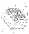
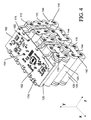
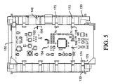
図2は、例示用の一実施形態による組み立てられた電池パック110の斜視図を示している。図3は、例示用の一実施形態の出力コネクタを示すべく、PCB及びセルコネクタが除去された状態における図2の電池パック110の斜視図を示している。図4は、例示用の一実施形態による、セルコネクタを示すべく、物理的セル接続組立体が除去された状態における図2の電池パック110の斜視図を示している。図5は、例示用の一実施形態による電池パック110の平面図を示しており、且つ、図6は、例示用の一実施形態によるセルコネクタのうちの一つのセルコネクタの側面図を示している。以下、図2〜図6を参照し、例示用の一実施形態について説明することとする。
FIG. 2 shows a perspective view of the assembled
図2から理解され得るように、例示用の一実施形態の電池パック110は、セルのうちのそれぞれのセルの長手方向センターラインが、第一方向において(例えば、Z方向)、実質的に相互に平行な状態においてアライメントされるように、実質的に相互に隣接した状態において配列され得る複数のセル120を含んでもよい。セルのいくつかは、更に、列において(例えば、Y方向に沿って)、且つ、行において(例えば、X方向に沿って)、相互にアライメントされてもよい。図2の例においては、それぞれが四つのセルを有する五つの列が存在するように、20個のセルが提供されている。但し、セルの数及びその構成は、様々な異なる例示用の実施形態において、異なってもよいことを理解されたい。
As can be seen from FIG. 2, the exemplary
例示用の一実施形態においては、セル120は、物理的セル接続組立体130により、定位置において保持されてもよく、物理的セル接続組立体130は、構造において、上述の物理的セル接続組立体30と類似したものであってもよい。従って、上述のように、物理的セル接続組立体130は、セル120がその内部に固定され得るエンクロージャ(この場合にも、完全に取り囲まれる必要はないものと理解し得る)を定義するべく、セル120の少なくとも両端部に係合するように構成されたセル保持器構造であってもよい。いくつかのケースにおいては、セル120は、その運動を抑制するべく、物理的セル接続組立体130内に形成されたスロット内においてフィットしてもよい。
In an exemplary embodiment, the
又、物理的セル接続組立体130は、電気的接続を目的としてセルのグループ化を促進するべくセルのうちの選択されたセルの電極に係合する個々のセルコネクタ142を定義した金属プレート又は導電体を含み得る電気的セル接続組立体140により、増強されてもよい。従って、セルのグループは、PCB150との組合せにおける電気的セル接続組立体140を介して任意の望ましい構成において直列接続及び/又は並列接続されてもよい。例えば、電気的セル接続組立体140のセルコネクタ142は、そのグループ内のセルのうちのそれぞれの端部のセルの負電極に接続されてもよく、且つ、これらのセルの並列接続を完成させるべく、更に、第二セルコネクタ(図示されてはいない)が、その反対側の端部におけるセルの正電極に接続されてもよい。次いで、グループは、セルのその他のグループとの間において、直列又は並列に更に接続されてもよい。
The physical
いくつかの実施形態においては、物理的セル接続組立体130は、電気的セル接続組立体130が、セルコネクタ142のうちの個々のセルコネクタの受け入れを介して電気的セル接続組立体140を受け入れるための、その内部に設けられた開口部132(図3を参照されたい)を有してもよい。従って、開口部132は、対応したセルコネクタ142の形状と実質的に類似した方式によって成形されてもよい。更には、いくつかの実施形態においては、開口部132は、開口部132内においてセルコネクタ142を保持するためにスナップフィットするか又はその他の方法で緊密な接続を提供するべく、セルコネクタ142上の突出部144がその内部において挿入され得るようにするコネクタスロット134を含んでもよい。セルコネクタ142は、本明細書において記述されているセル固定機能を促進するために増大したサイズを利用するべく、いくつかの従来のセルコネクタとの関係において、わずかに拡大されてもよい。
In some embodiments, the physical
例示用の一実施形態においては、セルコネクタ142のうちの一つ(例えば、電池パック110の出力が抽出されるセルコネクタ142のうちの一つ)は、検知回路とのやり取りを促進するべく(例えば、電池パック110の出力電流計測のために)使用され得るという点において、その他のセルコネクタ142と異なっていてもよい。図3においては、出力コネクタ146を露出させるべく、その他のセルコネクタ142が除去されており、且つ、PCB150が除去されている。出力コネクタ146は、一つ又は複数のセルの電極に接続してもよく、且つ、更には、出力ストラップ160に接続されてもよい。電池パック110の組み合わせられた出力は、収集されてもよく、且つ、電池パック110によって電力供給される装置の電気モータ及び/又は作業組立体に供給されてもよい。従って、出力ストラップ160は、電池パック110の出力端子に接続してもよく、次いで、これらの出力端子は、電池パック110が使用のために設置された際に、電力供給の対象である装置の入力端子と通信し得る。
In an exemplary embodiment, one of the cell connectors 142 (eg, one of the
電池パック110の電流の組み合わせられた出力は、出力コネクタ146を通過することから、出力コネクタ146は、組み合わせられた出力の値を判定すると共に/又は組み合わせられた出力を監視するべく、有用であろう。いくつかの実施形態においては、出力コネクタ146は、PCB150を通過するように構成されたはんだ付けタブを含んでもよい。はんだ付けタブは、少なくとも二つの計測タブ162と、一つの固定タブ164と、を含んでもよい。但し、固定タブ164は、必須ではない。計測タブ162は、電池パック110が組み立てられる際に、出力コネクタ146とPCB150との間のオーバーラップの、離隔すると共に遠い位置に配置された地点と関連する出力コネクタ146の各部分において配置されてもよい。可能な限り遠くに計測タブ162を配置することにより、これらの計測タブは、検知回路10(例えば、電流計測回路)に対するその電気的接続を促進するべくPCB150にはんだ付けされてもよく、且つ、これらの間の相対的に長い距離に基づいて、相対的に正確な計測値(例えば、電流計測値)が判定され得る。
Since the combined output of the current of the
又、計測タブ162及び固定タブ164は、固定機能を提供してもよく、その理由は、これらが、PCB150内の事前形成されたアパーチャ166を通過し得るからである。事前形成されたアパーチャ166は、少なくとも一つのその他のアパーチャ(即ち、少なくとも固定タブ164に関連したアパーチャ)が、中央において、或いは、PCB150のエッジから離隔した状態において、配置された状態において、少なくとも一つのこのようなアパーチャ(即ち、セル電極に最も近接した計測タブ162に関連したアパーチャ)が、PCB150のエッジ部分に近接するように、位置決めされてもよい。この結果、はんだ付けタブをPCB150にはんだ付けする前に、組み立てられた電池パック110を一つに保持するための相対的に大きな保持強度が実現され得る。この観点において、図5〜図6から理解され得るように、アパーチャ166は、はんだ付けタブ(例えば、計測タブ162及び固定タブ164)との間において緊密なフィットを生成するように、サイズ設定されてもよい。従って、アパーチャ166が、それぞれ、計測タブ162及び固定タブ164を受け入れるように、PCB150が出力コネクタ146上に設置された際に、PCB150は、定位置において保持されてもよい。図5及び図6に示されているように、計測タブ162及び固定タブ164は、セル120から離れるように延在する方向においてPCB150を通過してもよい。
The
又、その他のセルコネクタ142は、セル固定機能を提供する方式により、PCB150に接続されてもよい。この観点において、例えば、セルコネクタ142は、接触部分170と、保持部分172と、固定部分174と、を含んでもよい。セルコネクタ142のうちのそれぞれのセルコネクタの接触部分170は、セルのうちの少なくとも二つのセルの電極を電気的に接続するべく、第一方向に実質的に垂直である方向において(例えば、XYプレーン内において)延在するように、配設されてもよい。保持部分172は、PCB150のエッジに向かって、接触部分170から離れるように延在してもよい。例示用の一実施形態においては、保持部分172は、電池パック110が組み立てられる際に、物理的セル接続組立体130を保持すると共にこれをPCB150に向かって引っ張るように、物理的セル接続組立体130の一部分に係合してもよい。一方、固定部分174は、物理的セル接続組立体130との関係においてPCB150に係合し且つこれを保持するべく、(例えば、セル120に向かう、且つ、従って、その他の接続タブ又ははんだ付けタブ(計測タブ162及び固定タブ164)がPCB150を通過する方向とは反対の、方向において)PCB150を貫通してもよい。次いで、すべての残りのはんだ付けタブの固定部分174がはんだ付けされてもよい。
The
例示用の一実施形態においては、図6に示されているように、接触部分170及び保持部分172は、平行なプレーン(又は、同一のプレーン)内において位置してもよく、且つ、物理的セル接続組立体130のセル保持器の表面に対して平行に延在してもよい。次いで、セルコネクタ142は、セルコネクタ142がPCB150に接近する時点まで、セル保持器の一側部に沿って延在するべく、実質的に90度だけ、折れ曲がってもよく、そこで、セルコネクタ142は、PCB150のプレーンを過ぎて延在するように、実質的に90度だけ、戻るように折れ曲がってもよい。次いで、セルコネクタ142は、固定部分174がPCB150内に形成されたアパーチャ176を通過できるようにするべく、セル120に向かって折れ曲がって戻るように、C又はU字形状を形成してもよい。又、その後に、こちらも接続タブ又ははんだ付けタブであるものと見なされ得る固定部分174も、電気的接続を完成させると共にセル保持器によるPCB150の固定を促進するべく、PCB150にはんだ付け(又は、その他の方法で固定)されてもよい。
In one exemplary embodiment, as shown in FIG. 6, the
例示用の一実施形態においては、はんだ付けタブの任意の(又は、すべての)ものは、その上部に配設された保持クリップ190を含んでもよい。いくつかの実施形態の保持クリップ190は、それぞれ、PCB150を通じた保持クリップ190の挿入によって圧縮されるリテンションタブ192を含んでもよい。次いで、リテンションタブ192は、リテンションタブ192が、リテンションタブ192が挿入されるPCB150の側との関係におけるPCB150の反対の側に貫通するのに応答して、膨張し得る。換言すれば、リテンションタブ192は、リテンションタブ192がアパーチャ(166/176)のうちの一つを通じてスライドする圧縮された状態と、リテンションタブ192が手動で(例えば、操作者により)押し下げられない限り、PCB150からの保持クリップ192の退却を防止している膨張した状態と、をリテンションタブ192が有するように、保持クリップ190がPCB150との間においてスナップフィットを提供できるようにしてもよい。
In one exemplary embodiment, any (or all) of the soldering tabs may include a retaining
従って、電池パック110の組立工程は、物理的セル接続組立体130の一つのセル保持器内におけるセル120の配置ステップを含んでもよく、これは、その他のセル保持器の装着ステップによって後続される。次いで、図3に示されているように、その対応するセルに接触すると共に配列されたセル120の一側に沿って位置するように、出力コネクタ146が提供されてもよい。次いで、はんだ付けタブ(計測タブ162及び固定タブ164)が、その個々のアパーチャ166内において挿入されるように、PCB150が出力コネクタ146上において配置されてもよい。保持クリップ190が、はんだ付けタブ上において提供される場合には、保持クリップ190は、定位置にスナップ結合してもよく、且つ、はんだ付けタブを更に保持してもよい。又、いくつかのケースにおいては、物理的セル接続組立体130の一部分は、PCB130の受け入れ及びアライメントをガイドしてもよい(ガイドレール180を観察されたい)。この時点において、はんだ付けタブ(例えば、計測タブ162及び固定タブ164)がPCB150にはんだ付けされてもよい。但し、このはんだ付けは、必要に応じて、遅延されてもよく、その理由は、PCB150が、はんだ付けタブにより、(物理的セル接続組立体130の一つのセル保持器との間における且つPCB150との間におけるその剛性の係合を介して)定位置において保持されることになるからである。次いで、突出部144が、接触部分170を定位置において保持するべくコネクタスロット134内にフィット又なスナップ結合するように、その他のセルコネクタ142が開口部132に挿入されてもよい。接触部分170は、セル120の電極に接触してもよく、且つ、いくつかのケースにおいては、セル120に対して溶接されてもよい。一方、保持部分172は、固定部分174が、PCB150の反対側のエッジ(即ち、隣接するセルのセル電極に近接した反対側のエッジ)の周りにおいて形成された個々のアパーチャ176内にスナップ結合された際に、物理的セル接続組立体130の反対側のセル保持器を互いに向かって引っ張ってもよい。次いで、組立体を完成させるべく、残りのはんだ付けタブ(例えば、セルコネクタ142の固定部分174)のはんだ付けが実現されてもよい。必要に応じて、電池パック110は、バックパック内に又は屋外動力機械内に挿入可能であり得るハウジング内において提供されてもよい。
Therefore, the assembly process of the
図7は、例示用の一実施形態の電池パック110によって電力供給され得る屋外動力機械200のブロックダイアグラムを示している。図7に示されているように、電池パック110は、物理的セル接続組立体130と、電気的セル接続組立体140と、を含んでもよい。電気的セル接続組立体140は、セル120をPCB150に電気的に接続してもよく、且つ、更には、電池パック110のコンポーネントのはんだ付けの前に、このようなコンポーネントの定位置における且つ適切なアライメント状態における保持との関係において物理的セル接続組立体130を支援してもよい。従って、衝撃に起因して、或いは、位置のミスアライメントを有するはんだ付けによって生成される固有の応力に起因して、将来において障害が発生する可能性が高くない高品質のはんだ付け結合部が実現され得る。又、機械200の電気モータ220及び/又は機械200の作業組立体230に供給される出力電流を監視するべく、検知回路210が提供されてもよい。電流計測は、出力コネクタ146上の二つの地点の間における(即ち、計測タブ162の間における)電圧降下を判定することにより、実現され得る。例示用の一実施形態においては、電気的セル接続組立体140によって形成される電気的接続は、物理的セル接続組立体130のセル固定能力に寄与する構造的要素を使用して形成されている。更には、電気的セル接続組立体140は、デュアル機能の出力コネクタ146を使用して出力電流を計測するべく、検知回路210用の結合装置を提供してもよく、デュアル機能の出力コネクタは、電流計測機能用の電気的接続を実行すると共にPCB150の改善された固定のための構造をも提供する。
FIG. 7 shows a block diagram of an outdoor powered machine 200 that may be powered by an exemplary
例示用の実施形態は、位置を補正するためのセルコネクタの事前位置決めを促進するべく、機械的ロッキングメカニズムを利用している。従って、電池パック用の組立プロセスを改善及び単純化し得ると共に、製造品質を向上させることができる。又、例示用の実施形態によって利用されている機械的ロッキングメカニズムは、振動又は衝撃が電池パック上のはんだ付け接続を破壊又は損傷し得るリスクをも低減し得る。一実施形態においては、ロッキングメカニズムの一部分(例えば、出力コネクタ)は、検知回路とインタフェースすることにより、PCBと検知回路との間の接続を更に安定化させるように、更に構成されてもよい。従って、図7を参照すれば、検知回路210とPCB150との間の接続は、実際には、衝撃及び振動によって提供され得るはんだ付けされた結合部に対する影響を低減するべく、PCB150とセル120との間の物理的接続の一部分として内蔵されてもよい。
The illustrative embodiment utilizes a mechanical locking mechanism to facilitate pre-positioning of the cell connector to correct the position. Therefore, the assembly process for the battery pack can be improved and simplified, and the manufacturing quality can be improved. The mechanical locking mechanism utilized by the exemplary embodiment may also reduce the risk that vibrations or shocks can break or damage the soldered connections on the battery pack. In one embodiment, a portion of the locking mechanism (eg, output connector) may be further configured to further stabilize the connection between the PCB and the sensing circuit by interfacing with the sensing circuit. Thus, referring to FIG. 7, the connection between the
従って、例示用の一実施形態の電池パックは、セルのうちのそれぞれのセルの長手方向センターラインが、第一方向において、実質的に相互に平行な状態においてアライメントされるように、実質的に相互に隣接した状態において配列された複数のセルと、セル保持部分のペアを含む物理的セル接続組立体であって、そのそれぞれが、ハウジング内においてセルを実質的に取り囲むためのハウジングを定義するべくセルのうちのそれぞれのセルの個々の反対側の端部に接触するように配設されている、組立体と、グループのそれぞれと関連付けられたセルの電気的接続を促進するべくグループ内のセルのうちの少なくとも選択されたセルと接触するように配設された複数のセルコネクタを含む電気的セル接続組立体であって、セルコネクタのうちのそれぞれのセルコネクタの接触部分が、セルのうちの少なくとも二つのセルの電極を電気的に接続するべく第一方向に対して実質的に垂直である方向において延在するように配設されている、組立体と、PCBと電気的セル接続組立体との間の電気的通信に基づいてセルと関連付けられた電気的パラメータを監視するように構成された印刷回路板(PCB)と、を含んでもよい。PCBは、第一方向に対して実質的に平行であるプレーン内においてセルの一側に沿って延在してもよい。セル接続組立体の少なくとも一つのセルコネクタは、物理的セル接続組立体に係合する保持部分と、物理的セル接続組立体との関係におけるPCBの保持を促進するためにPCBに係合するべくPCBのプレーンに対して実質的に垂直に延在する固定部分と、を含んでもよい。 Accordingly, the battery pack of an exemplary embodiment is substantially configured such that the longitudinal centerlines of each of the cells are aligned in a first direction and substantially parallel to each other. A physical cell connection assembly including a plurality of cells arranged adjacent to each other and a pair of cell holding portions, each defining a housing for substantially surrounding the cells within the housing. To facilitate electrical connection between the assembly and the cell associated with each of the groups arranged to contact the respective opposite ends of each of the cells. An electrical cell connection assembly including a plurality of cell connectors disposed in contact with at least selected cells of the cells, the cell connector comprising: A contact portion of each cell connector extending in a direction substantially perpendicular to the first direction to electrically connect electrodes of at least two of the cells. An assembly and a printed circuit board (PCB) configured to monitor an electrical parameter associated with the cell based on electrical communication between the PCB and the electrical cell connection assembly. But you can. The PCB may extend along one side of the cell in a plane that is substantially parallel to the first direction. At least one cell connector of the cell connection assembly is adapted to engage the PCB to facilitate retention of the PCB in relation to the physical cell connection assembly and a retaining portion that engages the physical cell connection assembly. And a fixed portion extending substantially perpendicular to the plane of the PCB.
いくつかの実施形態の電池パックは、単独で又は相互の組合せにおいて、任意選択によって追加され得る更なる特徴を含んでもよい。この観点において、以下のそれぞれの付番された特徴は、単独で、或いは、その他の付番された特徴のうちの、任意の選択されたその他の特徴、或いは、場合によっては、すべて、との組合せにおいて、電池パックに追加されてもよい。例えば、いくつかの実施形態においては、(1)固定部分は、PCB内の事前形成されたアパーチャを通過するように構成された少なくとも一つのはんだ付けタブを含んでもよい。いくつかのケースにおいては、(2)固定部分は、PCBに対して少なくとも一つのセルコネクタを固定する保持クリップを更に含んでもよい。例示用の一実施形態においては、(3)はんだ付けタブは、保持クリップによって固定された後に、PCBに対してはんだ付けされるか、溶接されるか、或いは、その他の方法で固定されてもよい。いくつかの実施形態においては、(4)保持クリップは、リテンションタブを含んでもよく、リテンションタブは、PCBを通じた保持クリップの挿入によって圧縮されると共に、リテンションタブが、リテンションタブが挿入されるPCBの側との関係におけるPCBの反対の側に貫通するのに応答して膨張する。リテンションタブは、膨張した状態にある間に、PCBからの保持クリップの退却を防止し得る。いくつかのケースにおいては、(5)PCBは、電池パックの動作を監視する検知回路を更に含んでもよい。例示用の一実施形態においては、(6)固定部分は、二つのはんだ付けタブを含んでもよく、且つ、検知回路は、二つのはんだ付けタブの間における電気的接続を介して共通出力を監視するように構成されてもよい。いくつかの例においては、(7)固定部分は、PCBに固定部分をはんだ付けする前に、PCBの固定との関係における3点機械的支持のための更なるはんだ付けタブを含んでもよい。いくつかのケースにおいては、(8)二つのはんだ付けタブは、固定部分の反対側の端部の近傍において配設されてもよい。例示用の一実施形態においては、(9)二つのはんだ付けタブは、PCB内の対応するアパーチャを通じて提供された後に、PCBに対してはんだ付けされるか、溶接されるか、或いは、その他の方法によって固定されてもよい。いくつかの実施形態においては、(10)少なくともいくつかのセルコネクタの固定部分は、PCBの第一端部の近傍においてPCBに係合してもよく、且つ、少なくともいくつかのその他のセルコネクタの固定部分は、PCBの第一端部の反対側であるPCBの第二端部の近傍においてPCBに係合してもよい。いくつかの例においては、(11)少なくとも一つのセルコネクタの固定部分は、セルから離れる方向においてPCBを貫通する少なくとも二つのはんだ付けタブを含んでもよい。このような一例においては、セルコネクタのうちの少なくともいくつかのその他のセルコネクタは、それぞれ、対応する固定部分を含んでもよい。対応する固定部分は、セルに向かう方向においてPCBを貫通してもよい。いくつかのケースにおいては、(12)少なくとも二つのはんだ付けタブのうちの少なくとも一つは、対応する固定部分によって貫通されるPCBのエッジから離隔したPCBの一部分においてPCBを貫通してもよい。いくつかの実施形態においては、(13)対応する固定部分は、それぞれ、個々の保持クリップを含む。それぞれの保持クリップは、リテンションタブを含んでもよく、リテンションタブは、PCBを通じた挿入によって圧縮され、且つ、リテンションタブが、リテンションタブが挿入されるPCBの側との関係におけるPCBの反対の側に貫通することに応答して膨張する。リテンションタブは、膨張した状態においては、挿入方向とは反対の方向におけるPCBからのリテンションタブの退却を防止し得る。 The battery packs of some embodiments may include additional features that may optionally be added, alone or in combination with each other. In this respect, each of the following numbered features is either alone or any other selected number of other numbered features or, in some cases, all: In combination, it may be added to the battery pack. For example, in some embodiments, (1) the securing portion may include at least one soldering tab configured to pass through a pre-formed aperture in the PCB. In some cases, (2) the securing portion may further include a retaining clip that secures at least one cell connector to the PCB. In one exemplary embodiment, (3) the soldering tab may be soldered to the PCB, welded, or otherwise secured after being secured by the retaining clip. Good. In some embodiments, (4) the retaining clip may include a retention tab that is compressed by insertion of the retaining clip through the PCB and the retention tab is the PCB into which the retention tab is inserted. In response to penetrating the opposite side of the PCB in relation to the other side. The retention tab may prevent retraction of the retaining clip from the PCB while in the expanded state. In some cases, (5) the PCB may further include a detection circuit that monitors the operation of the battery pack. In an exemplary embodiment, (6) the fixed portion may include two soldering tabs and the sensing circuit monitors a common output via an electrical connection between the two soldering tabs. It may be configured to. In some examples, (7) the securing portion may include additional soldering tabs for three-point mechanical support in relation to securing the PCB before soldering the securing portion to the PCB. In some cases, (8) the two soldering tabs may be disposed near the opposite end of the securing portion. In one exemplary embodiment, (9) two soldering tabs are provided through corresponding apertures in the PCB and then soldered to the PCB, welded, or other It may be fixed by a method. In some embodiments, (10) the securing portion of at least some cell connectors may engage the PCB in the vicinity of the first end of the PCB, and at least some other cell connectors. May be engaged with the PCB in the vicinity of the second end of the PCB opposite the first end of the PCB. In some examples, (11) the securing portion of the at least one cell connector may include at least two soldering tabs that penetrate the PCB in a direction away from the cell. In such an example, at least some other cell connectors of the cell connectors may each include a corresponding securing portion. The corresponding fixed part may penetrate the PCB in the direction towards the cell. In some cases, (12) at least one of the at least two soldering tabs may penetrate the PCB in a portion of the PCB spaced from the edge of the PCB that is penetrated by the corresponding securing portion. In some embodiments, (13) each corresponding securing portion includes an individual retaining clip. Each retaining clip may include a retention tab that is compressed by insertion through the PCB, and the retention tab is on the opposite side of the PCB relative to the side of the PCB where the retention tab is inserted. Inflates in response to penetrating. In the expanded state, the retention tab can prevent the retention tab from retracting from the PCB in a direction opposite to the insertion direction.
いくつかの実施形態においては、上述のアイテム(1)〜(13)のうちのいずれか又はすべては、個別に、或いは、相互の組合せにおいて、提供されてもよく、且つ、電池パックは、屋外動力機械に電力供給するべく、操作者によって装用可能であるバックパック内において提供されてもよい。 In some embodiments, any or all of the above items (1)-(13) may be provided individually or in combination with each other, and the battery pack is outdoors It may be provided in a backpack that can be worn by the operator to power the power machine.
当業者には、以上の説明及び関連する図面において提示されている教示の利益を有する本明細書に記述されている本発明の多くの変更及びその他の実施形態が想起されよう。従って、本発明は、開示されている特定の実施形態に限定されるものではなく、且つ、変更及びその他の実施形態は、添付の請求項の範囲に含まれることが意図されていることを理解されたい。更には、以上の説明及び関連する図面は、要素及び/又は機能の特定の例示用の組合せの文脈において例示用の実施形態を記述しているが、添付の請求項の範囲を逸脱することなしに、要素及び/又は機能の異なる組合せが代替実施形態によって提供され得ることを理解されたい。この観点において、添付の請求項のいくつかにおいて記述されている場合があるように、例えば、明示的に上述されているもの以外の要素及び/又は機能の異なる組合せも想定される。利点、利益、又は問題に対する解決策が本明細書において記述されている場合に、そのような利点、利益、及び/又は解決策は、いくつかの例示用の実施形態に適用可能であってもよいが、必ずしも、すべての例示用の実施形態に対して適用可能であるわけではないことを理解されたい。従って、本明細書において記述されている任意の利点、利益、又は解決策が、すべての実施形態にとって又は本明細書において特許請求されているものにとって、必須であり、必要とされており、或いは、不可欠であると考えてはならない。本明細書においては、特定の用語が利用されているが、これらの用語は、限定を目的としてではなく、一般的且つ説明的な意味においてのみ、使用されている。 Those skilled in the art will envision many modifications and other embodiments of the invention described herein that have the benefit of the teachings presented in the foregoing description and the associated drawings. Accordingly, it is to be understood that the invention is not limited to the specific embodiments disclosed, and that modifications and other embodiments are intended to be included within the scope of the appended claims. I want to be. Moreover, the foregoing description and the associated drawings describe exemplary embodiments in the context of specific exemplary combinations of elements and / or functions without departing from the scope of the appended claims. In addition, it should be understood that different combinations of elements and / or functions may be provided by alternative embodiments. In this regard, for example, different combinations of elements and / or functions other than those explicitly described above are envisioned, as may be described in some of the appended claims. Where benefits, benefits, or solutions to problems are described herein, such benefits, benefits, and / or solutions may be applicable to some example embodiments. It should be understood that although not necessarily applicable to all exemplary embodiments. Accordingly, any advantage, benefit, or solution described herein is essential, required, or required for all embodiments or for what is claimed herein, or Do not consider it essential. Although specific terms are utilized herein, these terms are used in a general and descriptive sense only and not for purposes of limitation.
Claims (31)
複数のセルであって、該セルのうちのそれぞれのセルの長手方向センターラインが、第一方向において、実質的に相互に平行な状態においてアライメントされるように、実質的に相互に隣接する状態において配列された複数のセルと、
ハウジング内において該セルを保持するべく該セルのそれぞれに接触するように配設されたセル保持部分を含む物理的セル接続組立体と、
グループのそれぞれと関連付けられた該セルの電気的接続を促進するべく該グループ内の該セルのうちの少なくとも選択されたセルに接触するように配設された複数のセルコネクタを含む電気的セル接続組立体であって、該セルコネクタのうちのそれぞれのセルコネクタの接触部分は、該セルのうちの少なくとも二つのセルの電極を電気的に接続するように配設されている、電気的セル接続組立体と、
印刷回路板(PCB)であって、該PCBと該電気的セル接続組立体との間の電気的通信に基づいて該セルと関連付けられた電気的パラメータを監視するように構成された印刷回路板(PCB)と、
を具備し、該セル接続組立体の少なくとも一つのセルコネクタは、該物理的セル接続組立体に係合する保持部分と、該物理的セル接続組立体との関係における該PCBの保持を促進するために該PCBに係合するべく該PCBのプレーンに対して実質的に垂直に延在している固定部分と、を含む、電池パック。 A battery pack,
A plurality of cells substantially adjacent to each other such that the longitudinal centerlines of each of the cells are aligned in a first direction and substantially parallel to each other A plurality of cells arranged in
A physical cell connection assembly including a cell holding portion disposed to contact each of the cells to hold the cells within a housing;
An electrical cell connection comprising a plurality of cell connectors arranged to contact at least selected cells of the cells in the group to facilitate electrical connection of the cells associated with each of the groups An electrical cell connection, wherein the contact portion of each cell connector of the cell connectors is arranged to electrically connect electrodes of at least two cells of the cell An assembly;
A printed circuit board (PCB) configured to monitor electrical parameters associated with the cell based on electrical communication between the PCB and the electrical cell connection assembly (PCB)
And at least one cell connector of the cell connection assembly facilitates retention of the PCB in relation to the physical cell connection assembly and a retention portion that engages the physical cell connection assembly. And a fixed portion extending substantially perpendicular to the plane of the PCB to engage the PCB.
電気モータと、
該電気モータによって動力供給される作業組立体と、
該電気モータに電力供給するように構成された電池パックと、
を具備し、
該電池パックは、
複数のセルであって、該セルのうちのそれぞれのセルの長手方向センターラインが、第一方向において、実質的に相互に平行な状態においてアライメントされるように、実質的に相互に隣接する状態において配列された複数のセルと、
ハウジング内において該セルを保持するべく該セルのそれぞれと接触するように配設されたセル保持部分を含む物理的セル接続組立体と、
グループのそれぞれと関連付けられた該セルの電気的接続を促進するべく該グループ内の該セルのうちの少なくとも選択されたセルに接触するように配設された複数のセルコネクタを含む電気的セル接続組立体であって、該セルコネクタのうちのそれぞれのセルコネクタの接触部分は、該セルのうちの少なくとも二つのセルの電極を電気的に接続するように配設されている、電気的セル接続組立体と、
印刷回路板(PCB)であって、該PCBと該電気的セル接続組立体との間の電気的通信に基づいて該セルと関連付けられた電気的パラメータを監視するように構成された印刷回路板(PCB)と、
を具備し、
該セル接続組立体の少なくとも一つのセルコネクタは、該物理的セル接続組立体に係合する保持部分と、該物理的セル接続組立体との関係における該PCBの保持を促進するために該PCBに係合するべく該PCBのプレーンに対して実質的に垂直に延在している固定部分と、を含む、屋外動力機械。 An outdoor powered machine,
An electric motor;
A working assembly powered by the electric motor;
A battery pack configured to supply power to the electric motor;
Comprising
The battery pack
A plurality of cells substantially adjacent to each other such that the longitudinal centerlines of each of the cells are aligned in a first direction and substantially parallel to each other A plurality of cells arranged in
A physical cell connection assembly including a cell holding portion disposed to contact each of the cells to hold the cells within a housing;
An electrical cell connection comprising a plurality of cell connectors arranged to contact at least selected cells of the cells in the group to facilitate electrical connection of the cells associated with each of the groups An electrical cell connection, wherein the contact portion of each cell connector of the cell connectors is arranged to electrically connect electrodes of at least two cells of the cell An assembly;
A printed circuit board (PCB) configured to monitor electrical parameters associated with the cell based on electrical communication between the PCB and the electrical cell connection assembly (PCB)
Comprising
At least one cell connector of the cell connection assembly includes a retaining portion that engages the physical cell connection assembly and the PCB to facilitate retention of the PCB in relation to the physical cell connection assembly. A stationary portion that extends substantially perpendicular to the plane of the PCB to engage.
複数のセルであって、該セルのうちのそれぞれのセルの長手方向センターラインが、第一方向において、実質的に相互に平行な状態において配列されるように、実質的に相互に隣接した状態において配列された複数のセルと、
ハウジング内において該セルを保持するべく該セルのそれぞれと接触するように配設されたセル保持部分を含む物理的セル接続組立体と、
該一つ又は複数のセルの電気的接続を促進するべく該セルの一つ又は複数に接触するように配設されたセルコネクタを含む電気的セル接続組立体と、
印刷回路板(PCB)であって、該PCBと該電気的セル接続組立体との間の電気的通信に基づいて該セルと関連付けられた電気的パラメータを監視するように構成された印刷回路板(PCB)と、
を具備し、該セル接続組立体の該セルコネクタは、検知回路が該少なくとも二つの接続タブを介して該電池パックの共通出力を監視できるようにするべく、該PCBを貫通する少なくとも二つの接続タブ、を含む、電池パック。 A battery pack,
A plurality of cells substantially adjacent to each other such that the longitudinal centerlines of each of the cells are arranged in a substantially parallel manner in the first direction A plurality of cells arranged in
A physical cell connection assembly including a cell holding portion disposed to contact each of the cells to hold the cells within a housing;
An electrical cell connection assembly including a cell connector disposed to contact one or more of the cells to facilitate electrical connection of the one or more cells;
A printed circuit board (PCB) configured to monitor electrical parameters associated with the cell based on electrical communication between the PCB and the electrical cell connection assembly (PCB)
And the cell connector of the cell connection assembly includes at least two connections through the PCB to allow a sensing circuit to monitor the common output of the battery pack via the at least two connection tabs. A battery pack including a tab.
複数のセルであって、該セルのうちのそれぞれのセルの長手方向センターラインが、第一方向において、実質的に相互に平行な状態においてアライメントされるように、実質的に相互に隣接した状態において配列された複数のセルと、
ハウジング内において該セルを保持するべく該セルのそれぞれに接触するように配設されたセル保持部分を含む物理的セル接続組立体と、
グループのそれぞれと関連付けられた該セルの電気的接続を促進するべく該グループ内の該セルのうちの少なくとも選択されたセルに接触するように配設された複数のセルコネクタを含む電気的セル接続組立体であって、該セルコネクタのうちのそれぞれのセルコネクタの接触部分は、該セルのうちの少なくとも二つのセルの電極を電気的に接続するように配設されている、電気的セル接続組立板と、
印刷回路板(PCB)であって、該PCBと該電気的セル接続組立体との間の電気的通信に基づいて該セルと関連付けられた電気的パラメータを監視するように構成された印刷回路板(PCB)であって、該セル接続組立体の少なくとも一つのセルコネクタは、該物理的セル接続組立体との関係における該PCBの保持を促進するべくロッキング組立体を含む、印刷回路板(PCB)と、
を具備する電池パック。 A battery pack,
A plurality of cells substantially adjacent to each other such that longitudinal centerlines of each of the cells are aligned in a first direction in a substantially parallel state to each other A plurality of cells arranged in
A physical cell connection assembly including a cell holding portion disposed to contact each of the cells to hold the cells within a housing;
An electrical cell connection comprising a plurality of cell connectors arranged to contact at least selected cells of the cells in the group to facilitate electrical connection of the cells associated with each of the groups An electrical cell connection, wherein the contact portion of each cell connector of the cell connectors is arranged to electrically connect electrodes of at least two cells of the cell An assembly board;
A printed circuit board (PCB) configured to monitor electrical parameters associated with the cell based on electrical communication between the PCB and the electrical cell connection assembly A printed circuit board (PCB), wherein at least one cell connector of the cell connection assembly includes a locking assembly to facilitate retention of the PCB in relation to the physical cell connection assembly. )When,
A battery pack comprising:
Applications Claiming Priority (1)
| Application Number | Priority Date | Filing Date | Title |
|---|---|---|---|
| PCT/SE2013/051538 WO2015094035A1 (en) | 2013-12-17 | 2013-12-17 | Battery pack with cell fixing apparatus |
Publications (1)
| Publication Number | Publication Date |
|---|---|
| JP2017505512A true JP2017505512A (en) | 2017-02-16 |
Family
ID=53403209
Family Applications (1)
| Application Number | Title | Priority Date | Filing Date |
|---|---|---|---|
| JP2016539976A Pending JP2017505512A (en) | 2013-12-17 | 2013-12-17 | Battery pack having cell fixing device |
Country Status (6)
| Country | Link |
|---|---|
| US (1) | US10147979B2 (en) |
| EP (1) | EP3084857B1 (en) |
| JP (1) | JP2017505512A (en) |
| CN (1) | CN105830248B (en) |
| AU (1) | AU2013408456B2 (en) |
| WO (1) | WO2015094035A1 (en) |
Families Citing this family (16)
| Publication number | Priority date | Publication date | Assignee | Title |
|---|---|---|---|---|
| CN105070961B (en) * | 2015-07-30 | 2017-08-29 | 山东梅拉德能源动力科技有限公司 | A kind of echelon application process of battery standard module |
| JP6615622B2 (en) * | 2016-01-19 | 2019-12-04 | マレリ株式会社 | Assembled battery |
| KR101805546B1 (en) * | 2016-03-08 | 2017-12-07 | 삼성에스디아이 주식회사 | Battery pack having connection tab with bent portion |
| CN110313081B (en) * | 2017-02-23 | 2023-05-09 | 松下知识产权经营株式会社 | Battery module |
| KR102184368B1 (en) * | 2017-12-11 | 2020-11-30 | 삼성에스디아이 주식회사 | Battery pack |
| CN112292283A (en) * | 2018-05-04 | 2021-01-29 | 布里格斯斯特拉顿有限责任公司 | Modular battery assembly for battery powered devices |
| KR20200040025A (en) | 2018-10-08 | 2020-04-17 | 삼성에스디아이 주식회사 | Battery pack |
| KR102617730B1 (en) | 2018-10-08 | 2023-12-26 | 삼성에스디아이 주식회사 | Battery pack |
| KR20200040024A (en) | 2018-10-08 | 2020-04-17 | 삼성에스디아이 주식회사 | Battery pack |
| US11817731B2 (en) | 2018-10-12 | 2023-11-14 | Briggs & Stratton, Llc | Battery assembly for battery powered equipment |
| KR102220898B1 (en) | 2018-10-17 | 2021-02-26 | 삼성에스디아이 주식회사 | Battery pack |
| JP7177674B2 (en) * | 2018-11-30 | 2022-11-24 | 株式会社マキタ | battery pack |
| US11563239B2 (en) * | 2019-05-03 | 2023-01-24 | Black & Decker Inc. | Battery pack and method of manufacture |
| FR3112900B1 (en) * | 2020-07-27 | 2022-07-29 | Limatech | Serial modular block (B l M o S e ) |
| DE102020129780A1 (en) * | 2020-11-11 | 2022-05-12 | Elringklinger Ag | Device for measuring cell voltages in a module |
| DE102021129965A1 (en) * | 2021-11-17 | 2023-05-17 | HELLA GmbH & Co. KGaA | Energy store, method for producing an energy store and vehicle |
Citations (14)
| Publication number | Priority date | Publication date | Assignee | Title |
|---|---|---|---|---|
| JPS62211857A (en) * | 1986-03-11 | 1987-09-17 | Matsushita Electric Ind Co Ltd | Terminal mounted battery |
| JPH04136865U (en) * | 1991-06-11 | 1992-12-21 | セイコー電子部品株式会社 | battery terminal |
| US5213513A (en) * | 1992-02-27 | 1993-05-25 | Seatt Corporation | Electric terminal |
| JP2004319423A (en) * | 2002-06-27 | 2004-11-11 | Hitachi Maxell Ltd | Battery with terminal board |
| JP2006196277A (en) * | 2005-01-12 | 2006-07-27 | Sanyo Electric Co Ltd | Battery pack |
| US20080254356A1 (en) * | 2005-09-20 | 2008-10-16 | Metabowerke Gmbh | Rechargeable Battery Pack and Electrical Hand Tool Device |
| JP2008287985A (en) * | 2007-05-16 | 2008-11-27 | Sony Corp | Battery pack |
| JP2010146879A (en) * | 2008-12-19 | 2010-07-01 | Makita Corp | Battery pack of electric tool |
| US20120052332A1 (en) * | 2010-08-31 | 2012-03-01 | Samsung Sdi Co., Ltd. | Rechargeable battery pack |
| WO2012077404A1 (en) * | 2010-12-11 | 2012-06-14 | 三洋電機株式会社 | Battery pack |
| JP2013022022A (en) * | 2011-07-14 | 2013-02-04 | Makita Corp | Portable power source bag |
| JP2013071219A (en) * | 2011-09-28 | 2013-04-22 | Hitachi Koki Co Ltd | Connector device and power supply device provided with the same |
| JP2013114780A (en) * | 2011-11-25 | 2013-06-10 | Sanyo Electric Co Ltd | Battery pack |
| JP2013165067A (en) * | 2013-04-10 | 2013-08-22 | Toshiba Corp | Secondary battery pack |
Family Cites Families (21)
| Publication number | Priority date | Publication date | Assignee | Title |
|---|---|---|---|---|
| US5188536A (en) * | 1992-03-16 | 1993-02-23 | Compaq Computer Corporation | Space-saving insulation displacement type interconnect device for electrically coupling a ribbon connector to a printed circuit board |
| JPH07320708A (en) | 1994-05-24 | 1995-12-08 | Toshiba Battery Co Ltd | Battery pack |
| US5903154A (en) | 1997-04-08 | 1999-05-11 | Zhang; Chaojiong | Battery test contact assembly |
| US6262636B1 (en) * | 1998-07-20 | 2001-07-17 | Antec Corporation | Apparatus for reversing direction of signal flow in a broadband signal tap |
| US6324339B1 (en) * | 1999-11-29 | 2001-11-27 | Eveready Battery Company, Inc. | Battery pack including input and output waveform modification capability |
| KR100801635B1 (en) | 2004-11-02 | 2008-02-05 | 주식회사 엘지화학 | Member for Measurement of Cell Voltage And Temperature in Battery Pack |
| KR100816183B1 (en) * | 2005-09-22 | 2008-03-21 | 삼성에스디아이 주식회사 | Battery pack having conductive tab stuck in the hole formed in protective circuit board |
| KR100886571B1 (en) | 2006-08-07 | 2009-03-05 | 주식회사 엘지화학 | Battery Pack Case |
| KR100934466B1 (en) | 2006-09-25 | 2009-12-30 | 주식회사 엘지화학 | Connection member for electrical connection of battery cells |
| DE102006061270B4 (en) | 2006-12-22 | 2021-10-14 | Robert Bosch Gmbh | Battery pack and battery module |
| JP5284053B2 (en) * | 2008-11-17 | 2013-09-11 | 株式会社東芝 | Secondary battery pack |
| JP5543231B2 (en) * | 2010-01-27 | 2014-07-09 | 三洋電機株式会社 | Battery system |
| WO2011096863A1 (en) | 2010-02-05 | 2011-08-11 | Alelion Batteries Ab | Battery assembly |
| KR101106094B1 (en) | 2010-09-13 | 2012-01-18 | 삼성에스디아이 주식회사 | Battery pack |
| WO2013026490A1 (en) | 2011-08-25 | 2013-02-28 | Gardena Manufacturing Gmbh | Battery pack and battery powered tool |
| WO2013080136A1 (en) | 2011-12-02 | 2013-06-06 | Miljøbil Grenland As | A battery module |
| JP2013177106A (en) | 2012-02-03 | 2013-09-09 | Yamaha Motor Co Ltd | Battery module and saddle-type electric vehicle |
| WO2013131588A2 (en) * | 2012-03-05 | 2013-09-12 | Husqvarna Ab | Battery pack system |
| WO2013131551A1 (en) | 2012-03-05 | 2013-09-12 | Husqvarna Ab | Electrically symmetrical battery cell connector |
| WO2013139409A1 (en) | 2012-03-19 | 2013-09-26 | Husqvarna Ab | Battery pack thermal management system |
| CN104205410B (en) | 2012-04-05 | 2017-12-19 | 胡斯华纳有限公司 | Battery pack |
-
2013
- 2013-12-17 EP EP13899914.9A patent/EP3084857B1/en active Active
- 2013-12-17 AU AU2013408456A patent/AU2013408456B2/en active Active
- 2013-12-17 US US15/104,550 patent/US10147979B2/en active Active
- 2013-12-17 CN CN201380081691.6A patent/CN105830248B/en active Active
- 2013-12-17 JP JP2016539976A patent/JP2017505512A/en active Pending
- 2013-12-17 WO PCT/SE2013/051538 patent/WO2015094035A1/en active Application Filing
Patent Citations (14)
| Publication number | Priority date | Publication date | Assignee | Title |
|---|---|---|---|---|
| JPS62211857A (en) * | 1986-03-11 | 1987-09-17 | Matsushita Electric Ind Co Ltd | Terminal mounted battery |
| JPH04136865U (en) * | 1991-06-11 | 1992-12-21 | セイコー電子部品株式会社 | battery terminal |
| US5213513A (en) * | 1992-02-27 | 1993-05-25 | Seatt Corporation | Electric terminal |
| JP2004319423A (en) * | 2002-06-27 | 2004-11-11 | Hitachi Maxell Ltd | Battery with terminal board |
| JP2006196277A (en) * | 2005-01-12 | 2006-07-27 | Sanyo Electric Co Ltd | Battery pack |
| US20080254356A1 (en) * | 2005-09-20 | 2008-10-16 | Metabowerke Gmbh | Rechargeable Battery Pack and Electrical Hand Tool Device |
| JP2008287985A (en) * | 2007-05-16 | 2008-11-27 | Sony Corp | Battery pack |
| JP2010146879A (en) * | 2008-12-19 | 2010-07-01 | Makita Corp | Battery pack of electric tool |
| US20120052332A1 (en) * | 2010-08-31 | 2012-03-01 | Samsung Sdi Co., Ltd. | Rechargeable battery pack |
| WO2012077404A1 (en) * | 2010-12-11 | 2012-06-14 | 三洋電機株式会社 | Battery pack |
| JP2013022022A (en) * | 2011-07-14 | 2013-02-04 | Makita Corp | Portable power source bag |
| JP2013071219A (en) * | 2011-09-28 | 2013-04-22 | Hitachi Koki Co Ltd | Connector device and power supply device provided with the same |
| JP2013114780A (en) * | 2011-11-25 | 2013-06-10 | Sanyo Electric Co Ltd | Battery pack |
| JP2013165067A (en) * | 2013-04-10 | 2013-08-22 | Toshiba Corp | Secondary battery pack |
Also Published As
| Publication number | Publication date |
|---|---|
| EP3084857A4 (en) | 2017-06-28 |
| CN105830248B (en) | 2019-11-01 |
| US10147979B2 (en) | 2018-12-04 |
| US20170025717A1 (en) | 2017-01-26 |
| EP3084857A1 (en) | 2016-10-26 |
| EP3084857B1 (en) | 2023-12-06 |
| AU2013408456B2 (en) | 2019-01-31 |
| CN105830248A (en) | 2016-08-03 |
| AU2013408456A1 (en) | 2016-07-07 |
| WO2015094035A1 (en) | 2015-06-25 |
Similar Documents
| Publication | Publication Date | Title |
|---|---|---|
| JP2017505512A (en) | Battery pack having cell fixing device | |
| US11031728B2 (en) | Electrical connector | |
| EP3637502B1 (en) | Bus bar assembly for electrode lead bonding and battery module including same | |
| US8764852B2 (en) | Battery pack including an electric harness and method of manufacturing the same | |
| US9385401B2 (en) | Rechargeable battery pack and electrical hand tool device | |
| KR101106544B1 (en) | Cell cartridge | |
| KR101329252B1 (en) | Series connection apparatus of battery module | |
| CN104466078B (en) | Battery module with holder | |
| US8859122B2 (en) | Interconnect device for battery assembly | |
| JP2011527492A (en) | Storage battery electrical contact with multiple storage battery cells | |
| KR20160131265A (en) | Battery pack | |
| JP2012174507A (en) | Battery module | |
| KR20090022892A (en) | Conductive tab and battery pack having the same | |
| KR101158810B1 (en) | Protecting circuit board of battery pack and battery bpack having the same | |
| JP6865724B2 (en) | How to assemble the busbar module | |
| US9667006B2 (en) | Electrically symmetrical battery cell connector | |
| JP2018060665A (en) | Battery module | |
| WO2013149668A1 (en) | Battery pack | |
| EP2581964A1 (en) | Battery pack | |
| CN112103454B (en) | Wire holding structure and bus bar module | |
| KR20180010591A (en) | Battery pack | |
| KR102334789B1 (en) | Jig module | |
| KR20140024528A (en) | Connector | |
| JPWO2015125936A1 (en) | Power supply | |
| CN218101619U (en) | Bus bar, battery pack and battery module |
Legal Events
| Date | Code | Title | Description |
|---|---|---|---|
| A977 | Report on retrieval |
Free format text: JAPANESE INTERMEDIATE CODE: A971007 Effective date: 20170915 |
|
| A131 | Notification of reasons for refusal |
Free format text: JAPANESE INTERMEDIATE CODE: A131 Effective date: 20170926 |
|
| A521 | Request for written amendment filed |
Free format text: JAPANESE INTERMEDIATE CODE: A523 Effective date: 20171207 |
|
| A131 | Notification of reasons for refusal |
Free format text: JAPANESE INTERMEDIATE CODE: A131 Effective date: 20180410 |
|
| A601 | Written request for extension of time |
Free format text: JAPANESE INTERMEDIATE CODE: A601 Effective date: 20180710 |
|
| A521 | Request for written amendment filed |
Free format text: JAPANESE INTERMEDIATE CODE: A523 Effective date: 20180801 |
|
| A02 | Decision of refusal |
Free format text: JAPANESE INTERMEDIATE CODE: A02 Effective date: 20190108 |