JP2017505263A - Vehicle seats, especially automobile seats - Google Patents
Vehicle seats, especially automobile seats Download PDFInfo
- Publication number
- JP2017505263A JP2017505263A JP2016550220A JP2016550220A JP2017505263A JP 2017505263 A JP2017505263 A JP 2017505263A JP 2016550220 A JP2016550220 A JP 2016550220A JP 2016550220 A JP2016550220 A JP 2016550220A JP 2017505263 A JP2017505263 A JP 2017505263A
- Authority
- JP
- Japan
- Prior art keywords
- seat
- backrest
- vehicle seat
- slotted guide
- cable pull
- Prior art date
- Legal status (The legal status is an assumption and is not a legal conclusion. Google has not performed a legal analysis and makes no representation as to the accuracy of the status listed.)
- Pending
Links
- 230000005540 biological transmission Effects 0.000 description 7
- 230000000875 corresponding Effects 0.000 description 4
- 239000000789 fastener Substances 0.000 description 3
- 239000002184 metal Substances 0.000 description 3
- 230000003014 reinforcing Effects 0.000 description 2
- 230000001419 dependent Effects 0.000 description 1
- 238000010586 diagram Methods 0.000 description 1
- 238000000034 method Methods 0.000 description 1
- 230000002265 prevention Effects 0.000 description 1
- 230000036633 rest Effects 0.000 description 1
Images


Abstract
本発明は、座部(3)と、座部(3)に対して旋回軸(S)を中心に旋回可能な背もたれ(5)と、車両シート(1)の前後方向調節のための少なくとも1つのシートレール対(11、13)と、少なくとも1つのシートレール対(11、13)をロックするためのシートレールロック装置(17)とを有し、背もたれ(5)は、人を運ぶのに適した使用位置(5.1)と、背もたれ(5)が旋回軸(S)を中心に前方に旋回させられ且つシートレールロック装置(17)がボーデンケーブルユニット(80)によって解除されたイージーエントリー位置(5.2)とを取ることができ、背もたれ(5)を旋回させてイージーエントリー位置(5.2)から使用位置(5.1)の方向に戻すために制限力に打ち勝つ必要がある車両シート(1)、特に自動車シートに関する。本発明によれば、制限力はボーデンケーブルユニット(80)の補償ばねユニット(85)によって生じる。The present invention provides a seat portion (3), a backrest (5) that can pivot about a pivot axis (S) with respect to the seat portion (3), and at least one for adjusting the longitudinal direction of the vehicle seat (1). A pair of seat rails (11, 13) and a seat rail locking device (17) for locking at least one pair of seat rails (11, 13), the backrest (5) for carrying a person Suitable use position (5.1) and easy entry where the backrest (5) is pivoted forward about the pivot axis (S) and the seat rail locking device (17) is released by the Bowden cable unit (80) Position (5.2) can be taken and the backrest (5) must be swung to overcome the limiting force to return from the easy entry position (5.2) to the use position (5.1) Vehicle seat (1 And, more particularly, to a vehicle seat. According to the invention, the limiting force is generated by the compensating spring unit (85) of the Bowden cable unit (80).
Description
本発明は、車両シート、特に自動車シートであって、座部と、座部に対して旋回軸を中心に旋回可能な背もたれと、車両シートを前後方向に調節するための少なくとも1つのシートレール対と、少なくとも1つのシートレール対をロックするためのシートレールロック装置とを有し、背もたれは人を運ぶのに適した使用位置と、背もたれが旋回軸を中心に前方に旋回させられ且つシートレールロック装置がボーデンケーブルユニットによって解除されたイージーエントリー位置とを取ることができ、背もたれをイージーエントリー位置から使用位置の方向へ旋回させるために制限力に打ち勝つ必要がある車両シートに関する。 The present invention relates to a vehicle seat, in particular, an automobile seat, a seat portion, a backrest that can pivot about a pivot axis with respect to the seat portion, and at least one seat rail pair for adjusting the vehicle seat in the front-rear direction. And a seat rail locking device for locking at least one pair of seat rails, the backrest being used in a position suitable for carrying a person, and the backrest is pivoted forward about a pivot axis and the seat rail The present invention relates to a vehicle seat in which a locking device can take an easy entry position released by a Bowden cable unit and must overcome a limiting force in order to turn the backrest from the easy entry position toward the use position.
シートレール上で車両構造体に対して移動可能な座部と背もたれとを有する車両シートが使用によって知られている。背もたれは座部に対して旋回可能であり、車両シートの後ろに配置された更なる車両シート列にアクセスするのを容易にするためにイージーエントリー位置を取ることができる。このために、車両シートの背もたれは少なくとも部分的に前方へ旋回させられ、シートレールはボーデンケーブルユニットによって解除される。その後、背もたれを押すことによって車両シート全体を前方にスライドさせることができる。イージーエントリー位置に加えて、背もたれは荷床位置を取ることができ、荷床位置において背もたれはできる限り水平な位置に前方へ旋回させられている。この背もたれ位置はイージーエントリー位置を達成するのには適さないであろう。何故なら、車両シートのユーザーは背もたれが部分的にしか前方に旋回されていない状態で最もよく車両シートをスライドさせることができるからである。 Vehicle seats having a seat and a backrest that are movable relative to the vehicle structure on the seat rail are known in use. The backrest is pivotable relative to the seat and can take an easy entry position to facilitate access to further vehicle seat rows located behind the vehicle seat. For this purpose, the backrest of the vehicle seat is at least partially swiveled forward and the seat rail is released by the Bowden cable unit. Thereafter, the entire vehicle seat can be slid forward by pushing the backrest. In addition to the easy entry position, the backrest can assume a load floor position, where the backrest is swung forward to a position as horizontal as possible. This backrest position would not be suitable for achieving an easy entry position. This is because the vehicle seat user can best slide the vehicle seat with the backrest only partially turned forward.
特許文献1は、2ドア自動車用の取付具であって、前方にスライドさせられる車両シートと組み合わせたイージーエントリー位置へと前方に自由に旋回させられる背もたれによって後方乗員室にアクセスすることを容易にし且つ乗員による使用のために背もたれの異なる傾斜位置を利用可能にするのに役立つ取付具を開示している。例えば背もたれと座部との遷移領域における過度の詰め物を考えて、背もたれの望ましくない後方への旋回を防ぐために、キャッチを用いて背もたれを自由に旋回させた位置で固定するための手段が設けられる。キャッチは、例えば車両シートをスライドさせて前に取ったシートの前後方向位置に戻すときに、自由旋回操作要素によって再び解除することができる。 Patent Document 1 is an attachment for a two-door vehicle, and facilitates access to the rear passenger compartment by a backrest that is freely swiveled forward to an easy entry position combined with a vehicle seat that is slid forward. Also disclosed is a fixture that helps to make available different tilted positions of the backrest for use by the occupant. Means are provided for securing the backrest in a freely swiveled position using catches, for example in view of excessive stuffing in the backrest-seat transition area, to prevent undesirably backward swiveling of the backrest. . The catch can be released again by the free turning operation element, for example, when the vehicle seat is slid and returned to the front-rear direction position of the previously taken seat.
特許文献2は、車両シートの座部に対する車両シートの背もたれの傾きを設定するための設定取付具を有する車両シートであって、設定取付具が背もたれを主として少なくとも1つの使用位置から自由に旋回させた位置、すなわちイージーエントリー位置へと自由に旋回させるための自由旋回ユニットを含む車両シートを開示している。取付具はまた、座部に接続され且つ設定取付具を支持する取付具下側部品と、自由旋回ユニットに割り当てられ且つ背もたれに接続されている取付具上側部品とを有する。使用位置において、自由旋回ユニットはキャッチを用いて形状嵌合によりロックされる。イージーエントリー位置において、背もたれは、キャッチが取付具下側部品にある止め具と協働することによって取付具上側部品を固定するという点で前記キャッチによって圧力嵌めにより固定され、この過程で、取付具下側部品に留められ且つ背もたれのイージーエントリー位置においてキャッチに作用するばねを用いて圧力嵌めにより固定される。背もたれのイージーエントリー位置において、キャッチは、背もたれ上縁を引っ張ることによってキャッチに開モーメントが生じるように、セルフロック領域の外側で止め具と協働する。定められた制限力から開始し、結果としてキャッチへのばねの固定力に打ち勝ち、キャッチは取付具上側部品をそれが旋回して使用位置へ戻るように解放する。
第1ケーブルプルと、第2ケーブルプルと、補償ばねユニットとを有するボーデンケーブルユニットが、特許文献3に記載されている。制限力以下では、第1ケーブルプルは補償ばねユニットを介して第2ケーブルプルに堅固に接続されている。制限力を超えると、第1ケーブルプルの一端と第2ケーブルプルの一端との間の距離が延長されるように、第1ケーブルプル及び第2ケーブルプルと直列に接続されている補償ばねユニット内のばねが圧縮される。補償ばねユニットは、例えば過負荷防止装置として役立つ。 Patent Document 3 discloses a Bowden cable unit having a first cable pull, a second cable pull, and a compensation spring unit. Below the limit force, the first cable pull is firmly connected to the second cable pull via the compensation spring unit. A compensation spring unit connected in series with the first cable pull and the second cable pull so that the distance between the one end of the first cable pull and the one end of the second cable pull is extended when the limit force is exceeded The inner spring is compressed. The compensation spring unit serves as an overload prevention device, for example.
第1ケーブルプルと、第2ケーブルプルと、補償ばねユニットとを有し、制限力以下では第1ケーブルプルが補償ばねユニットを介して第2ケーブルプルに堅固に接続されているボーデンケーブルユニットが使用されている。制限力を超えると、第1ケーブルプルの一端と第2ケーブルプルの一端との間の距離が延長されるように、第1ケーブルプル及び第2ケーブルプルと直列に接続されている補償ばねユニット内のばねが伸張される。 A Bowden cable unit having a first cable pull, a second cable pull, and a compensation spring unit, wherein the first cable pull is firmly connected to the second cable pull via the compensation spring unit below the limit force. It is used. A compensation spring unit connected in series with the first cable pull and the second cable pull so that the distance between the one end of the first cable pull and the one end of the second cable pull is extended when the limit force is exceeded The inner spring is stretched.
本発明は、冒頭で述べたタイプの車両シートを改善するという課題、特により少ない構成要素で同様の機能を提供するという課題に基づいている。 The invention is based on the problem of improving the vehicle seat of the type mentioned at the outset, in particular of providing similar functions with fewer components.
本発明によれば、この課題は、車両シートであって、座部と、座部に対して旋回軸を中心に旋回可能な背もたれと、車両シートを前後方向に調節するための少なくとも1つのシートレール対と、少なくとも1つのシートレール対をロックするためのシートレールロック装置とを有し、背もたれは、人を運ぶのに適した使用位置と、背もたれが旋回軸を中心に前方に旋回させられ且つシートレールロック装置がボーデンケーブルユニットによって解除されたイージーエントリー位置とを取ることができ、背もたれを旋回させてイージーエントリー位置から使用位置の方向に戻すために制限力に打ち勝つ必要があり、制限力はボーデンケーブルユニットの補償ばねユニットによって生じる車両シートによって解決される。 According to the present invention, this object is a vehicle seat, which is a seat, a backrest that can be pivoted about a pivot axis with respect to the seat, and at least one seat for adjusting the vehicle seat in the front-rear direction. A pair of rails and a seat rail locking device for locking at least one pair of seat rails, the backrest being pivoted forward about a pivot axis with a use position suitable for carrying a person And the seat rail locking device can take the easy entry position released by the Bowden cable unit, and it is necessary to overcome the limiting force to turn the backrest back from the easy entry position to the direction of use. Is solved by the vehicle seat produced by the compensating spring unit of the Bowden cable unit.
背もたれをイージーエントリー位置に保持するばね力がボーデンケーブルユニットの補償ばねユニットによって生じるので、補償ばねユニットは更なる機能を担い、別個のばねを省くことができる。 Since the spring force that holds the backrest in the easy entry position is generated by the compensation spring unit of the Bowden cable unit, the compensation spring unit has an additional function and a separate spring can be omitted.
個別に又は互いに組み合わせて使用することができる有利な構成が従属請求項の主題である。 Advantageous configurations that can be used individually or in combination with each other are the subject matter of the dependent claims.
好ましくは、ボーデンケーブルユニットは、第1ケーブルプルと、第2ケーブルプルと、補償ばねユニットとを含む。制限力以下では、第1ケーブルプルは補償ばねユニットを介して第2ケーブルプルに堅固に接続されている。制限力を超えると、第1ケーブルプル及び第2ケーブルプルに接続されている補償ばねユニットのばねの長さが変更される。好ましくは、補償ばねユニットは、動作接続に関して第1ケーブルプルと第2ケーブルプルとの間に配置されているばねを有する。第1ケーブルプルとばねと第2ケーブルプルは直列に接続されることができる。 Preferably, the Bowden cable unit includes a first cable pull, a second cable pull, and a compensation spring unit. Below the limit force, the first cable pull is firmly connected to the second cable pull via the compensation spring unit. When the limit force is exceeded, the length of the spring of the compensation spring unit connected to the first cable pull and the second cable pull is changed. Preferably, the compensation spring unit has a spring arranged between the first cable pull and the second cable pull with respect to the operating connection. The first cable pull, the spring and the second cable pull can be connected in series.
補償ばねユニットの構造次第で、制限力を超えたときに補償ばねユニット内のばねは伸張され又は圧縮される。第1ケーブルプルの一端と第2ケーブルプルの一端との間の距離は、ばねが伸張されるときに延長されることができる。これは、例えばばねが引張コイルばねであり、引張コイルばねの第1端が第1ケーブルプルに接続され且つ引張コイルばねの第2端が第2ケーブルプルに接続されている場合である。 Depending on the structure of the compensation spring unit, the spring in the compensation spring unit is stretched or compressed when the limiting force is exceeded. The distance between one end of the first cable pull and one end of the second cable pull can be extended when the spring is stretched. This is the case, for example, when the spring is a tension coil spring, the first end of the tension coil spring is connected to the first cable pull and the second end of the tension coil spring is connected to the second cable pull.
別の好ましい補償ばねユニットは特許文献3に開示されている。補償ばねユニット内のばねは、第1ケーブルプルの一端と第2ケーブルプルの一端との間の距離が延長されるように圧縮される。 Another preferred compensation spring unit is disclosed in US Pat. The spring in the compensation spring unit is compressed such that the distance between one end of the first cable pull and one end of the second cable pull is extended.
好適な実施形態では、背もたれのイージーエントリー位置において、第1手段が第2手段と特に圧力嵌め又は形状嵌めロックにより協働することができ、手段の一方は背もたれに割り当てられ且つ手段の他方は座部に割り当てられ、制限力に打ち勝った後で且つ背もたれを旋回させている間に手段は互いに対して移動する。好ましくは、ボーデンケーブルユニットの第1ケーブルプルのケーブルプル端が手段の一方に留められ、第2ケーブルプルのケーブルプル端がシートレールロック装置に留められている。 In a preferred embodiment, in the easy entry position of the backrest, the first means can cooperate with the second means, in particular by a pressure-fit or shape-fit lock, one of the means being assigned to the backrest and the other of the means being seated. The means move relative to each other after being assigned to the part and overcoming the limiting force and while turning the backrest. Preferably, the cable pull end of the first cable pull of the Bowden cable unit is fastened to one of the means, and the cable pull end of the second cable pull is fastened to the seat rail locking device.
背もたれは、それ自体既知の2つの取付具を用いて座部にヒンジ結合されることができる。第1及び第2手段は、好ましくは正確に一方のシート側部に且つ取付具のシート中央に面する側に配置されている。 The backrest can be hinged to the seat using two fixtures known per se. The first and second means are preferably arranged precisely on one side of the seat and on the side facing the seat center of the fixture.
第1手段は、第1アームと第2アームとを有するロッカーとして具現化されることができる。第2手段はスロット付きガイドであることができる。ロッカーのアームの一方は、スロット付きガイドと協働することができる。詳細には、アームの一方に取り付けられた接触手段又はアームの一方に取り付けられたローラーがスロット付きガイドと協働することができる。この場合、アームとスロット付きガイドとの間の相対運動の際に、スロット付きガイドの輪郭がロッカーを旋回させるように、アーム又は接触手段又はローラーとスロット付きガイドとの間で接触が行われる。このようなロッカーは、例えば打ち抜かれた金属部品として、コスト効率よく製造されることができる。 The first means can be embodied as a rocker having a first arm and a second arm. The second means can be a slotted guide. One of the rocker arms can cooperate with a slotted guide. In particular, a contact means attached to one of the arms or a roller attached to one of the arms can cooperate with the slotted guide. In this case, contact is made between the arm or contact means or roller and the slotted guide such that the profile of the slotted guide pivots the rocker during relative movement between the arm and the slotted guide. Such lockers can be manufactured cost-effectively, for example as stamped metal parts.
好ましくは、ボーデンケーブルユニットは、一方の側がアームの他方に、他方の側がシートレールロック装置に留められている。ボーデンケーブルユニットの第1ケーブルプルのケーブルプル端はアームの他方に留められることができ、第2ケーブルプルのケーブルプル端部はシートレールロック装置に留められることができる。 Preferably, the Bowden cable unit is fastened to the other side of the arm on one side and to the seat rail locking device on the other side. The cable pull end of the first cable pull of the Bowden cable unit can be fastened to the other of the arms, and the cable pull end of the second cable pull can be fastened to the seat rail locking device.
好ましくは、ロッカーは座部に、特に座部の取付具下側部品に回転可能に留められている。この場合、取付具下側部品は取付具の第2取付具部品を座部に接続している。座部とロッカーとの間に別個のアダプターを省略することができる。しかしながら、ロッカーを取り付けるための追加のアダプターを設けることもできる。 Preferably, the rocker is rotatably fastened to the seat, in particular to the fixture lower part of the seat. In this case, the fixture lower part connects the second fixture part of the fixture to the seat. A separate adapter can be omitted between the seat and the rocker. However, an additional adapter for attaching the locker can also be provided.
有利には、スロット付きガイドは背もたれに強固に接続されている。この場合、スロット付きガイドは、背もたれ構造体に一体化されるか又は別個の部品として構成されることができる。スロット付きガイドを背もたれ構造体に一体化することにより、追加の構成要素を省略することができる。背もたれ構造体に接続されている別個に構成されたスロット付きガイドは、モジュール式の背もたれキットを可能にする。 Advantageously, the slotted guide is firmly connected to the backrest. In this case, the slotted guide can be integrated into the backrest structure or configured as a separate part. By integrating the slotted guide into the backrest structure, additional components can be omitted. A separately configured slotted guide connected to the backrest structure allows for a modular backrest kit.
好ましくは、スロット付きガイドは、使用位置に割り当てられた第1スロット付きガイド部と、制限力に打ち勝たない限り、ロッカーと協働することによって背もたれが旋回してイージーエントリー位置から使用位置の方向に戻るのを防ぐ第2スロット付きガイド部を有する。この場合、第2スロット付きガイド部は、好ましくはカムの形態で半径方向において第1スロット付きガイド部を越えて突出することができる。好ましくは、第1スロット付きガイド部は円弧の形で旋回軸を中心に湾曲している。 Preferably, the slotted guide has a first slotted guide portion assigned to the use position, and unless the limit force is overcome, the backrest pivots by cooperating with the locker to move from the easy entry position to the use position direction. A guide portion with a second slot for preventing the return to the position. In this case, the second slotted guide part can project beyond the first slotted guide part in the radial direction, preferably in the form of a cam. Preferably, the first slotted guide portion is curved around the pivot axis in the shape of an arc.
アーム又は接触手段又はローラーと第1スロット付きガイド部との間で接触が行われることができる。しかしながら、代わりに、第1スロット付きガイド部とアームでは全く接触が行われず、接触手段又はローラーが第2スロット付きガイド部及び必要に応じて第3スロット付きガイド部とのみ協働するように、ロッカーのアームは支持手段に当接することもできる。 Contact can be made between the arm or contact means or roller and the first slotted guide. However, instead, there is no contact between the first slotted guide and the arm, so that the contact means or roller only cooperates with the second slotted guide and optionally the third slotted guide. The rocker arm can also contact the support means.
ロッカーのレバー比、スロット付きガイドの輪郭及び/又は補償ばねユニットの特性線を変えることによって、車両シートの移動シーケンスを車両の特定の境界条件及び顧客の要求に最適に適合させることができる。 By changing the lever ratio of the rocker, the profile of the slotted guide and / or the characteristic line of the compensating spring unit, the vehicle seat movement sequence can be optimally adapted to the vehicle's specific boundary conditions and customer requirements.
図面に示される有利な例示的実施形態によって、本発明を以下の文でより詳細に説明する。しかしながら、本発明はこの例示的な実施形態に限定されるものではない。
車両シート1は以下の文で、互いに対して垂直な3つの空間方向によって定められるデカルト座標系で説明される。前後方向xが、車両に設置された車両シート1の場合、概ね水平方向に且つ好ましくは車両の通常の進行方向に対応する車両の前後方向に平行に延びている。前後方向xに対して垂直に延びる横方向が、同様に車両において水平に配向され、車両横方向に対して平行に延びている。垂直方向zが、前後方向xに対して垂直且つ横方向に対して垂直に延びている。車両に設置された車両シート1の場合、垂直方向zは車両垂直軸に対して平行に延びている。 The vehicle seat 1 is described in the following sentence in a Cartesian coordinate system defined by three spatial directions perpendicular to each other. In the case of the vehicle seat 1 installed in the vehicle, the front-rear direction x extends generally in the horizontal direction and preferably parallel to the front-rear direction of the vehicle corresponding to the normal traveling direction of the vehicle. The lateral direction extending perpendicularly to the front-rear direction x is likewise oriented horizontally in the vehicle and extends parallel to the vehicle lateral direction. The vertical direction z extends perpendicular to the front-rear direction x and perpendicular to the lateral direction. In the case of the vehicle seat 1 installed in the vehicle, the vertical direction z extends parallel to the vehicle vertical axis.
使用される位置及び方向の特定、例えば、前、後、上及び下は、従来通り進行方向に配向されている車両シート1の通常の着座姿勢にある乗員の視線方向に関係する。しかしながら、本発明による車両シート1は、他の向きに、例えば進行方向に対して横方向に設置することもできる。 Identification of the position and direction to be used, for example, front, rear, top and bottom, is related to the line-of-sight direction of the occupant in the normal seating posture of the vehicle seat 1 oriented in the traveling direction as usual. However, the vehicle seat 1 according to the invention can also be installed in other directions, for example transversely to the direction of travel.
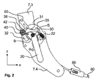
車両シート1は、座部3と、旋回軸Sを中心に座部3に対して旋回可能な背もたれ5とを有し、旋回軸Sは横方向に延び且つ2つの取付具7によって定められている。2つの取付具7は、この場合、2つの取付具7の一方のロック解除が必然的に他方の取付具7のロック解をもたらすように伝動ロッド9を介して互いに動作可能に接続され、伝動ロッド9は、この場合、同様に横方向に配向され且つ旋回軸Sと同心に配置されている。
The vehicle seat 1 includes a seat portion 3 and a
2つの取付具7の各々は、第1取付具部品7.1と、取付具7のロック解除で旋回軸Sを中心に第1取付具部品7.1に対して回転可能な第2取付具部品7.2とを含む。構造上の観点から、2つの取付具部品7.1及び7.2(及びクラスプ留めリング)は共に円盤状のユニットを形成する。取付具7の取り付けによって、第1取付具部品7.1は取付具上側部品7.3を用いて背もたれ5の構造体に強固に接続され、すなわち背もたれに固定されている。第2取付具部品7.2は、取付具下側部品7.4を用いて座部3の構造体に強固に接続され、すなわち座部に固定されている。2つの取付具7は、例えば独国特許出願公開第102009041492号明細書から知られているように、ラッチ取付具として構成されている。
Each of the two
車両シート1は、前後方向xにおいて前後に移動するように、前後方向xに配向され且つそれ自体既知の2つのシートレール対を用いて車両の車両構造体に取り付けられている。2つのシートレール対は、車両構造体に対して移動可能であり且つ互いに平行に配置された2つの第1レール11と、車両構造体に固定され且つ第1レール11の周りに係合し且つ第1レール11を案内する2つの関連する第2レール13とを含む。いずれの場合にもそれ自体既知の1つのシートレールロック装置17を用いて、それぞれの第1レール11をそれぞれの第2レール13に対してロックすることができる。シートレールロック装置17がロック解除されている状態で、第1レール11を第2レール13に対して移動させることができ、その結果、車両シート1の位置を前後方向xにおいて車両構造体に対して変えることができる。例示的な実施形態の変形例では、車両シート1は、具体的には2つのシートレール対の一方との間で作用する、正確に1つのシートレールロック装置17のみを有する。
The vehicle seat 1 is attached to the vehicle structure of the vehicle using two seat rail pairs that are oriented in the front-rear direction x and known per se so as to move back and forth in the front-rear direction x. The two seat rail pairs are movable with respect to the vehicle structure and are arranged in parallel to each other, two
車両シート1の背もたれ5は、垂直方向zに対して後方に向かって傾斜し且つ人を運ぶのに適している(図1に示される)使用位置5.1から、背もたれ5が座部3の上へ旋回軸Sを中心に前方へ旋回させられた荷床位置5.3とイージーエントリー位置5.2の両方に移動させることができる。イージーエントリー位置5.2では、背もたれ5は、垂直方向zに対して前方に旋回した位置へ旋回軸Sを中心に前方へ旋回されているが、荷床位置5.3の所までではない。また、イージーエントリー位置5.2に達すると、シートレールロック装置17がロック解除され、車両シート1を前方にスライドさせることができる。結果として、車両シート1の後方に配置され且つ図に示されていない後部シート列、特に第3シート列のシートのためにできるだけ大きな出入口領域を利用可能にすることができる。
The
荷床位置5.3では、背もたれ5はイージーエントリー位置5.2に対して更に前方に旋回され、好ましくは座部3の上に載っている。
In the loading position 5.3, the
背もたれ5のイージーエントリー位置5.2とは無関係のシートレールロック装置17のロック解除のために、従って前後方向xにおける車両シート1のセット性のために、車両シート1の前方領域において座部3の下に配置された旋回可能なバー15が設けられ、前記バー15の端部はそれ自体既知の方法でシートレールロック装置17に動作可能に接続されている。バー15は、バー15を引き上げることによってシートレール対11、13が手動でロック解除されることを可能にする。車両シート1は、バー15が引き上げられ且つ結果としてシートレールロック装置17が係合解除されたままである限り、予め定められた範囲内で前後方向xにスライドすることができる。バー15は、この場合、補強伝動棒に取り付けられ、補強伝動棒はバー15を引き上げると回転させられる。この伝達棒はシートの両側でそれぞれの第1レール11に取り付けられることができ、2つのシートレール対11、13の2つのシートレールロック装置17のロック状態を互いに連結する。
For the unlocking of the seat
操作要素20の作動が作動時に直接又は小さな遊びを経験した後に伝動ロッド9を回転させるように、操作要素20がシート外側で伝動ロッド9に動作可能に接続されている。結果として、2つの取付具7は解除され、背もたれ5は旋回軸Sを中心に座部3に対して旋回可能である。第1ばね22が、2つの取付具7がロックされる開始位置の方向へ作動方向と反対に操作要素20を付勢する。
The operating
背もたれ5の上部領域に、取付具7をロック解除するための、特に背もたれ5をイージーエントリー位置5.2へと前方に旋回させるための第2操作要素(図1には示されていない)を追加として設けることができ、前記第2操作要素は少なくとも間接的に操作要素20に連結されている。
In the upper region of the
この場合、使用位置5.1の周りの小さな快適角度範囲内(例えば後方に10°までと前方に2°まで)の旋回軸Sを中心とする背もたれ傾斜角度の精度設定を可能にする、背もたれ5の快適性設定も可能である。しかしながら、背もたれ5の快適性設定は省くこともできる。
In this case, it is possible to set the accuracy of the inclination angle of the backrest around the pivot axis S within the small comfortable angle range around the use position 5.1 (for example, up to 10 ° backward and 2 ° forward). A comfort setting of 5 is also possible. However, the comfort setting of the
少なくとも一方のシート外側に、キャッチ30が、キャッチ回転軸40を中心に回転可能であるように取付具下側部品7.4に取り付けられている。キャッチ回転軸40は、背もたれ5の旋回軸Sに対して偏心して、この場合は取付具下側部品7.4の、旋回軸Sの後方且つ上方に位置する領域に配置されている。キャッチ回転軸40は、この場合、それ自体既知の方法で取付具下側部品7.4にリベット留めされ又は取付具下側部品7.4にねじ込まれている第1軸受ボルト40の中心軸と同一である。
The
キャッチ30は、横方向において取付具下側部品7.4と操作要素20との間に配置されている。
The
キャッチ30は、互いの間に約50°の角度を含む第1脚部31と第2脚部32とを有するV字形である。しかしながら、本発明はこの角度に限定されるものではない。
The
第1脚部31と第2脚部32が合流する領域に、第1軸受ボルト40を受け入れるための、従ってキャッチ30を回転可能に取り付けるための開口部が設けられている。
In the region where the
第2ばね42がキャッチ30を、図2及び6における反時計方向に、取付具上側部品7.3に留められた止め具50に対して付勢する。止め具50は、この場合、取付具下側部品7.4の外側に係合する板金アングル材として構成されている。
The
キャッチ30の第1脚部31は、その第2脚部32と反対を向く側に、旋回軸Sの周りで湾曲した基本輪郭を有し、且つキャッチ旋回軸40に向かう方向に移動止め35が形成されるような切り欠きを有する。移動止め35は、背もたれ5のイージーエントリー位置5.2において止め具50と協働するのに役立つ。キャッチ回転軸40の方向において、第1脚部31の湾曲した外側基本輪郭は、背もたれ5の最後方位置において止め具50が当接する半径方向外側に突出する対の止め具38によって範囲を定められている。背もたれ5の最後方位置は、快適角度範囲のない取付具7の実施形態における使用位置5.1に対応する。
The
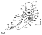
取付具下側部品7.4のシート中央を向く側には、横方向において見られるように、ロッカー60が、ロッカー回転軸66上で回転可能に取付具下側部品7.4に取り付けられている。ロッカー回転軸66は、背もたれ5の旋回軸Sに対して偏心して、この場合は取付具下側部品7.4の、旋回軸Sの下に位置する領域に配置されている。ロッカー回転軸66は、この場合、それ自体既知の方法で取付具下側部品7.4にリベット留めされ又は取付具下側部品7.4にねじ込まれている第2軸受ボルト66の中心軸と同一である。
On the side facing the seat center of the fixture lower part 7.4, the
ロッカー60は、互いの間に約135°の角度を含む第1アーム61と第2アーム62とを有するV字形である。しかしながら、本発明はこの角度に限定されるものではない。
The
第1アーム61と第2アーム62が合流する領域には、第2軸受ボルト66を受け入れるための、従ってロッカー60を回転可能に取り付けるための開口部が設けられている。
In the region where the
第1アーム61はロッカー回転軸66から離れたその端部にボーデンケーブル固定手段68、この場合はボーデンケーブルユニット80の第1ケーブルプル81を引っ掛けるための穴を有する。第2アーム62はロッカー回転軸66から離れたその端部にローラー65を有し、ローラー65は第2アーム62に回転可能に取り付けられ、取付具上側部品7.3に留められたスロット付きガイド70と連携して、接触手段として機能する。接触手段は、ローラー65として構成される必要はなく、例えば第2アーム62から形成されたカムであることもできる。
The
スロット付きガイド70は、旋回軸Sの周りに曲線状に延びるリングセグメントの形態の基本形状を有する。スロット付きガイド70は、この場合、取付具上側部品7.3に固定、特に溶接されているプレス加工板金部品であるが、例示的な実施形態の変形例において、取付具上側部品7.3から一体的に製造されることもできる。
The slotted
スロット付きガイド70は、制御輪郭として機能し且つロッカー60のローラー65と協働する、半径方向外側を向く外側輪郭を有する。第1スロット付きガイド部71が、背もたれ5の使用位置5.1においてローラー65の向かい側に位置している。第1スロット付きガイド部71から半径方向外側に突出する第2スロット付きガイド部が、カム72として構成され、背もたれ5を使用位置5.1からイージーエントリー位置5.2へと移動させるときにローラー65に当接し、旋回軸Sから離れる半径方向に前記ローラー65を押す。結果として、ロッカー60は(図3及び4において時計方向に)回転させられる。カム72のカム輪郭は、カム72と旋回軸Sとの間隔が第1スロット付きガイド部71から離れる方向に増大するように、旋回軸Sを中心にわずかに螺旋状に湾曲している。カム72は、周方向において第1スロット付きガイド部71に隣接する。
The slotted
第3スロット付きガイド部73が、周方向においてカム72の第1スロット付きガイド部71から離れた側に配置されている。第3スロット付きガイド部73は、カム72のカム輪郭に対して半径方向に更に内側に、第1スロット付きガイド部71に対して半径方向に更に外側に位置している。第3スロット付きガイド部73は、背もたれ5をイージーエントリー位置5.2から荷床位置5.3に移動させるときにローラー65の向かい側に位置する。
The
必要に応じて、支持体7.5を設けることができ、支持体7.5はこの場合はロッカー60の方向に取付具下側部品7.4からプレス加工され、背もたれ5の使用位置5.1において第1アーム61の、第2アーム62と反対を向く外側輪郭に当接する。これにより、背もたれ5の使用位置5.1において及び必要に応じて快適位置においてローラー65がスロット付きガイド70に当接する状況が回避される。
If necessary, a support body 7.5 can be provided, in which case the support body 7.5 is pressed from the lower part 7.4 of the fixture in the direction of the
ボーデンケーブルユニット80は、ロッカー60の旋回(図3、4、5、7、8及び9において時計方向の)がシートレールロック装置17を解除させるように、ロッカー60を2つのシートレールロック装置17に直接的又は間接的に接続する。
The
ボーデンケーブルユニット80は、第1ケーブルプル81と第2ケーブルプル(図に示さず)とを含む。第1ケーブルプル81は、ロッカー60のケーブルプル留め具68に留められ、詳細には引っ掛けられている。第2ケーブルプルは、2つのシートレールロック装置17に直接的又は間接的に接続されている。
The
第1ケーブルプル81及び第2ケーブルプルは、補償ばねユニット85を用いて互いに接続されている。補償ばねユニット85は、制限力以下では第1ケーブルプル81と第2ケーブルプルを互いに堅固に接続する。制限力を超えると、第1ケーブルプル81の一端と第2ケーブルプルの一端との間の距離が延長されるように、第1ケーブルプル81及び第2ケーブルプルと直列に接続されている補償ばねユニット85内のばねが伸張される。例示的な実施形態の変形例では、特許文献3に記載されるように、制限力を超えるとばねが圧縮され、結果として第1ケーブル81の一端と第2ケーブルプルの一端との間の距離が伸張されるように、第1ケーブルプル81及び第2ケーブルプルはばねと直列に接続される。
The
図2及び3は、背もたれ5の使用位置5.1における車両シート1の一部を示している。キャッチ30は止め具50によって開始角度位置に保持されている。ロッカー60は、ローラー65と第1スロット付きガイド部71との間に小さな隙間があるように支持手段7.5に当接している。
2 and 3 show a part of the vehicle seat 1 in the use position 5.1 of the
図4では、取付具7は(図4には示されていない操作レバー20の作動によって)ロック解除状態にあり、背もたれ5はイージーエントリー位置5.2の方向に前方へ振り動かされているが、イージーエントリー位置5.2には達していない。ローラー65がスロット付きガイド70のカム72に接触するとすぐに、ロッカー60はロッカー回転軸66を中心に偏向させられる。結果として、シートレールロック装置17は、ボーデンケーブルユニット80によってロック解除される。背もたれ5のイージーエントリー位置5.2の方向への更なる旋回時に、ロッカー60は、旋回軸Sを中心に螺旋状に湾曲しているカム72のカム輪郭のために更に偏向させられる。シートレールロック装置17が既に完全に解除状態にあり且つエンドストップにあるので、更なる移動は補償ばねユニット85によって吸収される。
In FIG. 4, the
シートレールロック装置17をロック解除するのに必要な力は、補償ばねユニット85の制限力よりも小さい。これにより、補償ばねユニット85が有効になり且つボーデンケーブルユニット80の伸張を引き起こす前に、シートレールロック装置17がロック解除されることが保証される。
The force required to unlock the seat
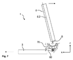
図5及び6は、背もたれ5のイージーエントリー位置5.2における、すなわちイージーエントリー位置5.2に達した後の車両シート1の一部を示す。ローラー65は今や、周方向に見られるように、カム72のすぐ後ろでカム72に当接している。止め具50が移動止め35に当接するように第2ばね42がキャッチ30を回転させたので、背もたれ5は荷床位置5.3の方向に更に前方へ旋回させることができない。補償ばねユニット85は弛緩している。例示的な実施形態の変形例では、補償ばねユニット85はこの領域でわずかにプレテンションされたままである(ローラー65は第2スロット付きガイド部72に当接している)。シートレールロック装置17はロック解除されている。車両シート1は、後部シート列への進入空間を増大させるためにレール11、13を用いて開始位置からイージーエントリー位置へと前方にスライドさせることができる。
5 and 6 show a part of the vehicle seat 1 at the easy entry position 5.2 of the
セルフロック領域の外側でローラー65に当接するカム72は、背もたれ5が使用位置5.1の方向に旋回して戻るのを防ぐ。背もたれ5を旋回させて戻すためには、背もたれ5の上部領域に戻り旋回力F3を加える必要があり、補償ばねユニット85内のばねが伸張されるように、この力は少なくとも補償ばねユニット85の制限力に打ち勝つのに十分な大きさでなければならない。補償ばねユニット85はこのようにカム72と協働して旋回軸Sを中心とする前方への制限トルクを生成し、背もたれ5を旋回させて再び使用位置5.1に戻すことができるようにするためにはこれに打ち勝つ必要がある。
The
カム72の輪郭を変えることによって、戻り旋回力F3を望み通りに調節することができる。戻り旋回力F3は、ロッカー60及びキャッチ30のレバー伝動及びレバー比を変えることによっても影響され得る。
By changing the contour of the
背もたれ5をイージーエントリー位置5.2から更に荷床位置5.3の方向に旋回させるために、操作要素20を(図2及び6において反時計方向に)再び作動されなければならない。この過程で、操作要素20はキャッチ30の第2脚部32に当接し、止め具50がキャッチ30の移動止め35を越えて旋回することができるように(図2及び6における時計回り方向に)キャッチ30を旋回させる。シートレールロック装置17は、ローラー65と第3スロット付きガイド部73との接触のために荷床位置5.3においても解除されたままである。しかしながら、第3スロット付きガイド部73の輪郭は、背もたれ5の荷床位置5.3において、シートレールロック装置17が再びロック解除されるように変えることができる(荷床位置5.3での係合機能)。例示的な実施形態の変形例では、補償ばねユニット85によるわずかな予張力が、第3スロット付きガイド部73のローラー65による力をもたらす。この力は、背もたれ5の旋回動作中にダンピングとして機能する。
In order to pivot the
車両シート1をスライドさせて前方のイージーエントリー位置から開始位置へ戻すとき、そのために必要なレール移動力は、車両シート1のユーザーによって背もたれ5に加えられる戻り旋回力F3の前後方向xに配向される力成分より少ない。これにより、車両シート1がまず前後方向xにおいて開始位置へと、従ってエンドストップまで移動され、その後でローラー65がカム72に打ち勝つことができ、結果として背もたれ5を旋回させて使用位置5.1へ戻すことができることが保証される。
When the vehicle seat 1 is slid to return from the front easy entry position to the start position, the rail moving force necessary for this is oriented in the front-rear direction x of the return turning force F3 applied to the
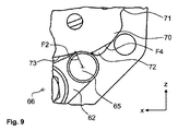
図8及び9には、背もたれ5を旋回させてイージーエントリー位置5.2から使用位置5.1へ戻す直前の車両シート1の力比率が概略的に且つ簡略化して示されている。
8 and 9 schematically and simply show the force ratio of the vehicle seat 1 immediately before the
補償ばねユニット85は、ロッカー回転軸66から第1の距離L1にあるボーデンケーブル留め具68の点に第1の力F1を生じる。第1の力F1は、旋回軸Sとボーデンケーブル留め具68との間を結ぶ線に対してほぼ垂直である。第1アーム61と第2アーム62との異なる長さと、それによるレバー比のために、第2アーム62は、第3スロット付きガイド部73に対してほぼ半径方向の第2の力F2で、旋回軸Sから第2の距離L2に配置されたローラー65を押す。この場合、以下が関係する。F2=F1*L1/L2。ローラー65とスロット付きガイド70との接触点は、L2と従ってF2が連続的に変化するように、F2を増加するにつれて、第3スロット付きガイド部73からカム72へと動く。
The compensating
戻り旋回力F3は、第3の力として、背もたれ5の上部領域においてユーザーによって開始される。第3の距離L3が、旋回軸Sと戻り旋回力F3の開始点との距離として定められる。第4の距離L4が、旋回軸Sとローラー65とカム72との接触点との距離として定められる。
The return turning force F3 is started by the user in the upper region of the
旋回軸Sを中心とする存在しているレバー比のために、戻り旋回力F3は、旋回軸Sから第4の距離L4に位置するローラー65とカム72との接触点に第4の力F4を生じる。以下が関係する。F4=F3*L3/L4。
Due to the lever ratio present around the pivot axis S, the return pivot force F3 is the fourth force F4 at the contact point between the
第4の力F4はカム72によってロッカー回転軸66を中心としてロッカー60にトルクをもたらし、前記トルクは第1の力F1によって生じるロッカー60へのトルクに対抗する。ローラー65がカム72を越えて移動することができるように、第4の力F4の第2の力F2と反対に作用する力成分が、ロッカー回転軸66を中心に第2の力F2よりも大きなトルクを発生させることができる。第4の力F4のこの力成分は、カムの輪郭によって決まる。輪郭が急峻になるほど、第4の力F4のF2と反対方向に作用する力成分も小さくなる。
The fourth force F4 causes a torque to the
上記明細書、特許請求の範囲及び図面に開示された特徴は、本発明を様々な形態で実現するために、個別と組み合わせの両方で重要であり得る。 The features disclosed in the above specification, claims and drawings may be important both individually and in combination in order to implement the invention in various forms.
1 車両シート
3 座部
5 背もたれ
5.1 (背もたれの)使用位置
5.2 (背もたれの)イージーエントリー位置
5.3 (背もたれの)荷床位置
7 取付具
7.1 第1取付具部品
7.2 第2取付具部品
7.3 取付具上側部品
7.4 取付具下側部品
7.5 支持手段
9 伝動ロッド
11 (シートレール対の)第1レール
13 (シートレール対の)第2レール
15 バー
17 シートレールロック装置
20 操作要素
22 第1ばね
30 キャッチ
31 第1脚部
32 第2脚部
35 移動止め
38 対の止め具
40 キャッチ回転軸、第1軸受ボルト
42 第2ばね
50 止め具
60 第1手段、ロッカー
61 第1アーム
62 第2アーム
65 接触手段、ローラー
66 ロッカー回転軸、第2軸受ボルト
68 ボーデンケーブル固定手段
70 第2手段、スロット付きガイド
71 第1スロット付きガイド部
72 第2スロット付きガイド部、カム
73 第3スロット付きガイド部
80 ボーデンケーブルユニット
81 第1ケーブルプル
85 補償ばねユニット
F1 第1の力
F2 第2の力
F3 第3の力、戻り旋回力
F4 第4の力
L1 第1の距離
L2 第2の距離
L3 第3の距離
L4 第4の距離
x 前後方向
z 垂直方向
S 旋回軸
DESCRIPTION OF SYMBOLS 1 Vehicle seat 3
Claims (15)
前記背もたれ(5)は、人を運ぶのに適した使用位置(5.1)と、前記背もたれ(5)が前記旋回軸(S)を中心に前方に旋回させられ且つ前記シートレールロック装置(17)がボーデンケーブルユニット(80)によって解除されたイージーエントリー位置(5.2)とを取ることができ、前記背もたれ(5)を旋回させて前記イージーエントリー位置(5.2)から前記使用位置(5.1)の方向に戻すために制限力に打ち勝つ必要があり、
前記制限力は前記ボーデンケーブルユニット(80)の補償ばねユニット(85)によって生じることを特徴とする、車両シート(1)。 A vehicle seat (1), in particular an automobile seat, comprising a seat (3), a backrest (5) pivotable about a pivot axis (S) relative to the seat (3), and the vehicle seat ( 1) at least one seat rail pair (11, 13) for adjusting the front and rear direction and a seat rail locking device (17) for locking the at least one seat rail pair (11, 13). And
The backrest (5) has a use position (5.1) suitable for carrying a person, the backrest (5) is swung forward about the swivel axis (S), and the seat rail locking device ( 17) can take the easy entry position (5.2) released by the Bowden cable unit (80), and the backrest (5) is swung to move from the easy entry position (5.2) to the use position. In order to return to the direction of (5.1), it is necessary to overcome the limiting force,
Vehicle seat (1), characterized in that the limiting force is generated by a compensation spring unit (85) of the Bowden cable unit (80).
Applications Claiming Priority (2)
| Application Number | Priority Date | Filing Date | Title |
|---|---|---|---|
| DE102014202315.7 | 2014-02-07 | ||
| DE102014206537.2 | 2014-04-04 |
Publications (1)
| Publication Number | Publication Date |
|---|---|
| JP2017505263A true JP2017505263A (en) | 2017-02-16 |
Family
ID=
Cited By (2)
| Publication number | Priority date | Publication date | Assignee | Title |
|---|---|---|---|---|
| CN108082202A (en) * | 2017-12-25 | 2018-05-29 | 上海坦达轨道车辆座椅系统有限公司 | A kind of attacker's device |
| CN109720243A (en) * | 2017-10-31 | 2019-05-07 | 日本发条株式会社 | Seat slide mechanism |
Cited By (3)
| Publication number | Priority date | Publication date | Assignee | Title |
|---|---|---|---|---|
| CN109720243A (en) * | 2017-10-31 | 2019-05-07 | 日本发条株式会社 | Seat slide mechanism |
| CN108082202A (en) * | 2017-12-25 | 2018-05-29 | 上海坦达轨道车辆座椅系统有限公司 | A kind of attacker's device |
| CN108082202B (en) * | 2017-12-25 | 2023-12-29 | 上海坦达轨道车辆座椅系统有限公司 | Buckle device |
Similar Documents
| Publication | Publication Date | Title |
|---|---|---|
| US20160347209A1 (en) | Vehicle seat, in particular motor vehicle seat | |
| EP2261078B1 (en) | Erroneous operation preventing device and stowable seat for vehicle | |
| US8967719B2 (en) | Easy entry seat system with single position memory and hold open feature | |
| US8517328B2 (en) | Single point easy entry seat latch for a vehicle seat | |
| US6631952B1 (en) | Automobile seat | |
| US7775591B2 (en) | Fitting system for a vehicle seat | |
| US10155460B2 (en) | Locking device, especially for locking a backrest of a vehicle seat to a vehicle structure | |
| US10286814B2 (en) | Easy entry seat assembly with recliner lockout mechanism | |
| US10493869B2 (en) | Backrest adjuster for a seat, and vehicle seat | |
| US20100171351A1 (en) | Fitting for a vehicle seat | |
| US8967583B2 (en) | Manually longitudinally adjustable motor vehicle seat | |
| US10052983B2 (en) | Fold and tumble mechanism for a vehicle seat | |
| EP3395608B1 (en) | Automobile seat | |
| US10150393B2 (en) | Fitting with a pivoting-forwards mechanism and easy-entry latch, and vehicle seat with such a fitting | |
| US9010862B2 (en) | Seat frame structure | |
| US10421374B2 (en) | Forward pivot mechanism for a vehicle seat, and vehicle seat | |
| US20170158101A1 (en) | Four-way ratcheting vehicle head restraint assembly | |
| US20160039316A1 (en) | Easy-entry system for a vehicle seat, and vehicle seat | |
| US20200238862A1 (en) | Vehicle seat having an easy-entry mechanism | |
| US20040135412A1 (en) | Motor vehicle seat | |
| US20090250987A1 (en) | Motor vehicle seat having lockable wing rest and seating configuration having such a motor vehicle seat | |
| US9586503B1 (en) | Vehicle seat and torsion bar | |
| US20170088023A1 (en) | Vehicle seat with hook and cam latching mechanism | |
| EP3243695B1 (en) | Vehicle seat | |
| US20070284919A1 (en) | Vehicle Seat With Pivotable Flap |