JP2017505214A - Artificial knee joint - Google Patents
Artificial knee joint Download PDFInfo
- Publication number
- JP2017505214A JP2017505214A JP2016568159A JP2016568159A JP2017505214A JP 2017505214 A JP2017505214 A JP 2017505214A JP 2016568159 A JP2016568159 A JP 2016568159A JP 2016568159 A JP2016568159 A JP 2016568159A JP 2017505214 A JP2017505214 A JP 2017505214A
- Authority
- JP
- Japan
- Prior art keywords
- tibial
- condyle
- post
- cam
- femoral
- Prior art date
- Legal status (The legal status is an assumption and is not a legal conclusion. Google has not performed a legal analysis and makes no representation as to the accuracy of the status listed.)
- Granted
Links
- 210000000629 knee joint Anatomy 0.000 title claims abstract description 17
- 210000003127 knee Anatomy 0.000 claims description 34
- 210000000689 upper leg Anatomy 0.000 claims description 18
- 210000002303 tibia Anatomy 0.000 claims description 14
- 210000002414 leg Anatomy 0.000 description 8
- 238000005452 bending Methods 0.000 description 7
- 206010003246 arthritis Diseases 0.000 description 3
- 210000002967 posterior cruciate ligament Anatomy 0.000 description 3
- 210000001264 anterior cruciate ligament Anatomy 0.000 description 2
- 210000004439 collateral ligament Anatomy 0.000 description 2
- 230000001419 dependent effect Effects 0.000 description 2
- 238000001727 in vivo Methods 0.000 description 2
- 208000014674 injury Diseases 0.000 description 2
- 210000003041 ligament Anatomy 0.000 description 2
- 238000012986 modification Methods 0.000 description 2
- 230000004048 modification Effects 0.000 description 2
- 230000008733 trauma Effects 0.000 description 2
- 208000036487 Arthropathies Diseases 0.000 description 1
- 208000018084 Bone neoplasm Diseases 0.000 description 1
- 208000012659 Joint disease Diseases 0.000 description 1
- 206010031264 Osteonecrosis Diseases 0.000 description 1
- 206010061926 Purulence Diseases 0.000 description 1
- 230000002159 abnormal effect Effects 0.000 description 1
- 239000003522 acrylic cement Substances 0.000 description 1
- 238000007792 addition Methods 0.000 description 1
- 230000015572 biosynthetic process Effects 0.000 description 1
- 210000000988 bone and bone Anatomy 0.000 description 1
- 230000000295 complement effect Effects 0.000 description 1
- 239000007943 implant Substances 0.000 description 1
- 238000002513 implantation Methods 0.000 description 1
- 208000015181 infectious disease Diseases 0.000 description 1
- 230000002757 inflammatory effect Effects 0.000 description 1
- 230000003993 interaction Effects 0.000 description 1
- 239000000203 mixture Substances 0.000 description 1
- 230000008529 pathological progression Effects 0.000 description 1
- 230000001737 promoting effect Effects 0.000 description 1
- 230000001172 regenerating effect Effects 0.000 description 1
- 206010039073 rheumatoid arthritis Diseases 0.000 description 1
- 238000000926 separation method Methods 0.000 description 1
- 238000001356 surgical procedure Methods 0.000 description 1
Images


Classifications
-
- A—HUMAN NECESSITIES
- A61—MEDICAL OR VETERINARY SCIENCE; HYGIENE
- A61F—FILTERS IMPLANTABLE INTO BLOOD VESSELS; PROSTHESES; DEVICES PROVIDING PATENCY TO, OR PREVENTING COLLAPSING OF, TUBULAR STRUCTURES OF THE BODY, e.g. STENTS; ORTHOPAEDIC, NURSING OR CONTRACEPTIVE DEVICES; FOMENTATION; TREATMENT OR PROTECTION OF EYES OR EARS; BANDAGES, DRESSINGS OR ABSORBENT PADS; FIRST-AID KITS
- A61F2/00—Filters implantable into blood vessels; Prostheses, i.e. artificial substitutes or replacements for parts of the body; Appliances for connecting them with the body; Devices providing patency to, or preventing collapsing of, tubular structures of the body, e.g. stents
- A61F2/02—Prostheses implantable into the body
- A61F2/30—Joints
- A61F2/38—Joints for elbows or knees
- A61F2/3886—Joints for elbows or knees for stabilising knees against anterior or lateral dislocations
-
- A—HUMAN NECESSITIES
- A61—MEDICAL OR VETERINARY SCIENCE; HYGIENE
- A61F—FILTERS IMPLANTABLE INTO BLOOD VESSELS; PROSTHESES; DEVICES PROVIDING PATENCY TO, OR PREVENTING COLLAPSING OF, TUBULAR STRUCTURES OF THE BODY, e.g. STENTS; ORTHOPAEDIC, NURSING OR CONTRACEPTIVE DEVICES; FOMENTATION; TREATMENT OR PROTECTION OF EYES OR EARS; BANDAGES, DRESSINGS OR ABSORBENT PADS; FIRST-AID KITS
- A61F2/00—Filters implantable into blood vessels; Prostheses, i.e. artificial substitutes or replacements for parts of the body; Appliances for connecting them with the body; Devices providing patency to, or preventing collapsing of, tubular structures of the body, e.g. stents
- A61F2/02—Prostheses implantable into the body
- A61F2/30—Joints
- A61F2/38—Joints for elbows or knees
- A61F2/3859—Femoral components
-
- A—HUMAN NECESSITIES
- A61—MEDICAL OR VETERINARY SCIENCE; HYGIENE
- A61F—FILTERS IMPLANTABLE INTO BLOOD VESSELS; PROSTHESES; DEVICES PROVIDING PATENCY TO, OR PREVENTING COLLAPSING OF, TUBULAR STRUCTURES OF THE BODY, e.g. STENTS; ORTHOPAEDIC, NURSING OR CONTRACEPTIVE DEVICES; FOMENTATION; TREATMENT OR PROTECTION OF EYES OR EARS; BANDAGES, DRESSINGS OR ABSORBENT PADS; FIRST-AID KITS
- A61F2/00—Filters implantable into blood vessels; Prostheses, i.e. artificial substitutes or replacements for parts of the body; Appliances for connecting them with the body; Devices providing patency to, or preventing collapsing of, tubular structures of the body, e.g. stents
- A61F2/02—Prostheses implantable into the body
- A61F2/30—Joints
- A61F2/38—Joints for elbows or knees
- A61F2/389—Tibial components
Abstract
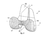
【課題】大腿骨コンポーネント(11)および脛骨コンポーネントを備える、人工膝関節を提供する。【解決手段】大腿骨コンポーネント(11)は、内顆(13)と、外顆(14)と、前壁(50)とを備える。内顆(13)および外顆(14)は、大腿骨カム(17)で顆間溝(19)の後部に近接して結合され、その延長の残りの部分の顆間溝(19)で仕切られる。脛骨コンポーネントは、脛骨プレートおよび脛骨インサート(12)を備える。脛骨インサート(12)は、内顆(13)および外顆(14)を支持するように構成され、そして、脛骨ポスト(18)を備える。大腿骨カム(17)は、非対称であり、そして、脛骨ポスト(18)で関節接合する、ドラム形状の遠位面(20)を備える。【選択図】図1An artificial knee joint comprising a femoral component (11) and a tibial component is provided. A femoral component (11) comprises an inner condyle (13), an outer condyle (14), and an anterior wall (50). The inner condyle (13) and the outer condyle (14) are joined in proximity to the rear of the intercondylar groove (19) with a femoral cam (17) and separated by the intercondylar groove (19) of the remaining part of the extension. It is done. The tibial component comprises a tibial plate and a tibial insert (12). The tibial insert (12) is configured to support the internal condyle (13) and the external condyle (14) and includes a tibial post (18). The femoral cam (17) is asymmetric and includes a drum-shaped distal surface (20) that articulates with a tibial post (18). [Selection] Figure 1
Description
本発明は生体膝関節を置き換えるために使用可能な人工膝関節に関する。 The present invention relates to an artificial knee joint that can be used to replace a living knee joint.
外傷に起因するか、または感染症、外傷後関節症、慢性関節リウマチ、炎症性関節炎、半月板切除術、骨壊死または骨腫瘍によって、生体膝が例えば一次性または二次性関節症を発症する場合、または、生体膝が特に重篤な外傷または他の類似の関節症を発症する場合、生体膝と置き換えるために、人工膝関節または膝プロテーゼが用いられる。 Living knees develop primary or secondary arthritis, for example, due to trauma or due to infection, posttraumatic arthritis, rheumatoid arthritis, inflammatory arthritis, meniscectomy, osteonecrosis or bone tumor In some cases, or when the living knee develops particularly severe trauma or other similar arthropathy, an artificial knee joint or knee prosthesis is used to replace the living knee.
公知の膝プロテーゼは、通常、大腿骨の遠位端に装着される大腿骨コンポーネントと、脛骨の近位端に装着される脛骨コンポーネントとを備える。 Known knee prostheses typically comprise a femoral component attached to the distal end of the femur and a tibial component attached to the proximal end of the tibia.
大腿骨コンポーネントは通常、その主要構成要素として、内顆(ないか)および外顆(がいか)、(内顆と外顆とは互いに部分的に顆間溝で仕切られる)と、前壁と、を有する。 The femoral component usually has as its main components: the inner condyle (not) and the outer condyle (the inner and outer condyles are partially separated from each other by an intercondylar groove), the anterior wall, Have.
脛骨コンポーネントは通常、脛骨プレートと、インサートと、を備える。脛骨プレートは、装着時は脛骨の近位端に取り付けられ、そして、インサートは、内側関節面および外側関節面を備え、装着時は大腿骨コンポーネントの内顆と外顆がそれぞれ内側関節面および外側関節面で関節接合する。 The tibial component typically comprises a tibial plate and an insert. The tibial plate is attached to the proximal end of the tibia when worn, and the insert comprises an inner articular surface and an outer articular surface, and when worn, the inner and outer condyles of the femoral component are respectively the inner articular surface and the outer articular surface. Articulate at the joint surface.
顆および関節面は、全体として、健康な生体膝と同様の動きを再現するように構成される。 The condyles and articulating surfaces are generally configured to reproduce movement similar to a healthy living knee.
より詳しくは、前、後、内側、または外側方向の異常な並進および、回転による、不適切な動きが発生する確率を可能な限り低下させるように、通常、大腿骨コンポーネントおよび脛骨コンポーネントは構成される。 More specifically, femoral and tibial components are typically configured to reduce as much as possible the probability of inadequate movement due to abnormal translation and rotation in the anterior, posterior, medial or lateral direction. The
膝全体の人工インプラントを使用する外科手術では、一般的に前十字靱帯が取り出される。 In surgery using an artificial implant for the entire knee, the anterior cruciate ligament is typically removed.
例えば病理の進行により、機能が損傷していると考えられる場合、または、全く機能しない場合は、代わりに後十字靭帯が取り出される。 If, for example, the function is considered damaged due to pathological progression or if it does not function at all, the posterior cruciate ligament is removed instead.
人工関節を全体的に安定させるためには、2つの側副靱帯(内側および外側靭帯)の存在が必要である。 The presence of two collateral ligaments (inner and outer ligaments) is necessary to stabilize the prosthesis as a whole.
前十字靭帯および後十字靭帯が取り出され、かつ同時に、側副靱帯の良好な機能が維持されるときに、本来の機械的安定性を復元できる補綴用構成物を使用することが必要である。 It is necessary to use a prosthetic composition that can restore the original mechanical stability when the anterior cruciate ligament and the posterior cruciate ligament are removed and at the same time the good functioning of the collateral ligament is maintained.
いくつかの公知のプロテーゼの解決策において、通常この構成物により、中心域にある脛骨インサートに設ける近位突起(脛骨インサート自体の内側と外側関節面の間に位置)を備えた、脛骨ポスト(または単にポスト)を設けることができる。 In some known prosthetic solutions, this arrangement usually provides a tibial post (with a proximal projection (located between the medial and lateral articular surfaces of the tibial insert itself)) on the tibial insert in the central region. Or just a post).
脛骨ポストは、プロテーゼが埋め込まれる大腿骨コンポーネントの顆間溝に挿入される。 The tibial post is inserted into the intercondylar groove of the femoral component in which the prosthesis is implanted.
いくつかの公知のプロテーゼの解決策において、ポストはまた、大腿骨カム(または単にカム)と干渉(接触)する。カムは、取り出された後十字靭帯の機能を回復するために、顆間溝の後部の付近、または前壁の反対側に位置する。 In some known prosthetic solutions, the post also interferes (contacts) with the femoral cam (or simply the cam). The cam is located near the posterior part of the intercondylar groove or on the opposite side of the anterior wall to restore the function of the removed posterior cruciate ligament.
ポストおよびカムは、通常は、関節の窪んだ湾曲部で結合する。 The post and cam are usually joined at the concave curvature of the joint.
脚が屈曲する際、生体膝内で、脛骨軸に対する外旋運動(外側に向かっての回転運動)が発生する。そして、この回転は人工関節を備える人工膝にも起こる。 When the leg is bent, an external rotation motion (rotational motion toward the outside) with respect to the tibial axis occurs within the living knee. This rotation also occurs in an artificial knee equipped with an artificial joint.
この種の回転の大きさは、具体的には個々の患者の個別の条件によって異なる。従って、回転角が一定になるようにポストとカムを接触させることは勧められない。しかし、より広い範囲で外旋できるように、ポストおよびカムの位置関係を最適化することは有効である。 The magnitude of this type of rotation specifically depends on the individual conditions of the individual patient. Therefore, it is not recommended that the post and the cam are in contact with each other so that the rotation angle is constant. However, it is effective to optimize the positional relationship between the post and the cam so that external rotation can be performed in a wider range.
従って、この理由のために、十分に広い可動範囲を許容すると共に異なる角度での外旋の接触ができるように、回転時に相互に接触することとなるポストおよびカムの領域は、非対称な設計とされ、すなわちぴったりとは嵌まる(合致する)ようにはしない設計とされる。 Therefore, for this reason, the post and cam regions that will contact each other during rotation are allowed to be asymmetrical in design so as to allow a sufficiently wide range of motion and allow external rotation contact at different angles. In other words, it is designed not to fit snugly (match).
先行技術文献の欧州特許第1591082号、米国特許出願公開第2012/0143342号、米国特許第2007135925号、米国特許第6013103号、欧州特許出願公開第0941719号、米国特許第5549686号、および、Catesらによる科学論文「In Vivo Comparison of Knee Kinematics for Subjects Having Either a Posterior Stabilized or Cruciate Retaining High−Flexion Total Knee Arthoplarty」には、屈曲間の外旋から生じる課題を少なくとも部分的に解決するために提唱された、関節膝プロテーゼの解決策が記載されている。 Prior art documents European Patent No. 1591082, US Patent Application Publication No. 2012/0143342, US Patent No. 200007135925, US Patent No. 6013103, European Patent Application Publication No. 0941719, US Pat. No. 5,549,686, and Cates et al. A scientific paper by "In Vivo Comparison of Knee Kinetics for Subjects for Having Eiter a Poster Stabilized or Cruciate Reducing High-Flexion Tot." A joint knee prosthesis solution is described.
しかしながら、これらの先行技術文献で提案される解決策は完全に満足できるものではない。なぜなら、いくつかの実施形態において、カムは、外旋運動の際に、カムおよびポストが適切な同一形状の結合が許容されないような、対称形の外形プロファイルを有するためである。 However, the solutions proposed in these prior art documents are not completely satisfactory. This is because, in some embodiments, the cam has a symmetric profile that prevents the cam and post from being properly joined together during external rotation.
いくつかの公知の実施形態の他のデメリットは、屈曲運動間の外旋が、大腿骨カムと脛骨ポストとの接触によって強引に行われるということである。そのため、動きが不自然になると同時にカムとポストの両方の摩耗を促進させる結果となる。 Another disadvantage of some known embodiments is that the external rotation during the flexion movement is forced by contact between the femoral cam and the tibial post. This results in unnatural movement and at the same time promoting wear on both the cam and post.
摩耗の促進は、膝プロテーゼの寿命低下につながりうる。 The accelerated wear can lead to a reduced life of the knee prosthesis.
いくつかの公知の実施形態において、脛骨インサートは、カムと接触させるため、ポストに非対称な接触面がある。 In some known embodiments, the tibial insert has an asymmetric contact surface on the post for contact with the cam.
このような非対称の接触面によって、単一の脛骨インサートを用いて、左右の大腿骨コンポーネントを交換することができない。 Such asymmetric contact surfaces do not allow the left and right femoral components to be exchanged using a single tibial insert.
従って、本発明の目的は、脚の自然な動きを容易にする人工膝関節を提供し、そして、健康的な膝の自然な運動機能を完全に再現することにある。 Accordingly, it is an object of the present invention to provide an artificial knee joint that facilitates natural movement of the legs and to perfectly reproduce the natural motion function of a healthy knee.
本発明の他の目的は、大腿骨コンポーネントと脛骨コンポーネント間の相互に働く応力を低減する人工膝関節を得ることにある。 Another object of the present invention is to provide a knee prosthesis that reduces the mutual stress between the femoral component and the tibial component.
出願人は、関節の状態の欠点を克服して、これらの目的とその他の目的および利点を得るために、本発明を考案して、テストして、実施した。 Applicants have devised, tested and implemented the present invention in order to overcome the shortcomings of joint conditions and obtain these and other objects and advantages.
独立クレームが、本発明を記載して特徴付け、従属クレームが、本発明の他の特徴、又は本発明の主要な着想に対する変形形態を表す。 The independent claims describe and characterize the invention, and the dependent claims represent other features of the invention or variations on the main idea of the invention.
上記の目的に従って、本発明による人工膝関節は、大腿骨の遠位端に装着可能な大腿骨コンポーネントを備える。大腿骨コンポーネントは、少なくとも内顆および外顆を備える。人工膝関節はまた、脛骨の近位端に装着可能な脛骨コンポーネントを備える。脛骨コンポーネントは、脛骨プレートおよび脛骨インサートを備える。 In accordance with the above objectives, a knee prosthesis according to the present invention comprises a femoral component that is attachable to the distal end of the femur. The femoral component comprises at least an internal condyle and an external condyle. The knee prosthesis also includes a tibial component that is attachable to the proximal end of the tibia. The tibial component comprises a tibial plate and a tibial insert.
脛骨インサートは内顆および外顆を支持するように構成される。そして、内顆および外顆がそれぞれ内側関節面および外側関節面で、関節接合することができる。 The tibial insert is configured to support the internal and external condyles. The inner condyle and outer condyle can be articulated at the medial and lateral articular surfaces, respectively.
脛骨インサートは、対称形のポスト(長手方向の2つの関節面の間に配置)を中央に備え、その結果、ポストは大腿骨の顆間溝(内顆および外顆が定める)の内部に配置される。大腿骨の顆間溝は、大腿骨コンポーネントの後部から前壁まで伸びる。 The tibial insert is centered with a symmetrical post (placed between two longitudinal articulating surfaces) so that the post is placed inside the intercondylar groove of the femur (defined by the internal and external condyles) Is done. The intercondylar groove of the femur extends from the posterior part of the femoral component to the anterior wall.
大腿骨コンポーネントはまた、カム(以下大腿骨カムと記載)を備える。そして、大腿骨カムは、関節が屈曲する際の或る時点に、ポストの後部面と接触する顆間溝の後側部分付近に配置される。 The femoral component also includes a cam (hereinafter referred to as a femoral cam). The femoral cam is then placed near the posterior portion of the intercondylar groove that contacts the posterior surface of the post at some point when the joint bends.
脛骨ポストおよび大腿骨カムは、大腿骨カムがポストと接触するときに、大腿骨コンポーネントの外旋を容易にするように成形される。 The tibial post and femoral cam are shaped to facilitate external rotation of the femoral component when the femoral cam contacts the post.
いくつかの実施形態において、大腿骨カムは、中央の大腿骨面に対して垂直な軸に沿って延びる。さらにまた、大腿骨カムは、円弧の、上記軸に対する回転によって定められる遠位面を備える。 In some embodiments, the femoral cam extends along an axis that is perpendicular to the central femoral surface. Still further, the femoral cam includes a distal surface defined by rotation of the arc with respect to the axis.
他の好ましい形成において、ポストは、脛骨インサートの中央面に対して対称である。 In another preferred formation, the post is symmetrical with respect to the midplane of the tibial insert.
この左右対称により、異なる右脚用大腿骨コンポーネントまたは左脚用大腿骨コンポーネントの脛骨コンポーネントを置き換えることができる。 This left / right symmetry can replace the tibial component of a different right leg or left leg femoral component.
大腿骨コンポーネント自体の形態、そして、具体的には大腿骨カムの形態が、特定の脚に対して最適化されるので、これが可能となる。 This is possible because the configuration of the femoral component itself, and specifically the configuration of the femoral cam, is optimized for a particular leg.
本発明の他の特徴によると、ポストの後部面はカムの接触面にぴったりとは合致しない。その結果、カムとポストは屈曲の際、外旋が可能となり、中央接触域を生じる。 According to another feature of the invention, the rear face of the post does not fit snugly with the contact surface of the cam. As a result, the cam and post are capable of external rotation when bent, creating a central contact area.
上記の特徴により作製される人工膝関節は、非常に自然に、生体膝の生理的な動きを再現する。 The artificial knee joint produced by the above features reproduces the physiological movement of a living knee very naturally.
さらに、この構成により、公知の人工膝関節において、大腿骨コンポーネントおよび脛骨コンポーネントが通常受ける応力が低減される。 In addition, this configuration reduces the stresses typically experienced by femoral and tibial components in known knee prostheses.
本発明のこれらの特徴および他の特徴は、添付の図面を参照して非限定的な実施例として与えられる、いくつかの実施形態の以下の説明から明らかになる。 These and other features of the present invention will become apparent from the following description of several embodiments, given by way of non-limiting example with reference to the accompanying drawings.
理解しやすくするために、可能であれば、図面中の同一の共通の要素を識別するために、同じ参照番号が使用されている。実施形態の一形態の要素及び特性は、さらなる説明がなくても、実施形態の他の形態に好適に組み込むことができることを理解されたい。 For ease of understanding, the same reference numerals have been used, where possible, to identify the same common elements in the drawings. It should be understood that elements and characteristics of one form of embodiment may be suitably incorporated into other forms of embodiment without further explanation.
我々はこれより、一つ以上の実施例が添付の図面に示される本発明のさまざまな実施形態について、詳細に言及する。 We now refer in detail to various embodiments of the invention, one or more examples of which are illustrated in the accompanying drawings.
各実施例は、本発明の例証として提供されて、限定するものとして理解されない。例えば、1つの実施形態の一部であると示されるかまたは記載される特徴は、新たな実施形態を生じる他の実施形態に、または、関連して採用されることができる。本発明がすべてのこの種の変更態様および変形例を含むものと理解される。 Each example is provided by way of illustration of the invention and is not understood as limiting. For example, features shown or described as being part of one embodiment can be employed in or in conjunction with other embodiments that yield new embodiments. It is understood that the present invention includes all such variations and modifications.
人工膝関節または膝プロテーゼ(以降、人工関節10と示す)の実施形態を記載するために図1〜3を用いる。 1-3 are used to describe an embodiment of an artificial knee joint or knee prosthesis (hereinafter referred to as an artificial joint 10).
人工関節10は、大腿骨(図面に示されない)の遠位端に装着するのに適した大腿骨コンポーネント11と、脛骨の近位端(図面に示されない)に、脛骨プレート(従来型であり、本発明の目的に関係がないため、図面に示さない)を用いて装着するのに適した脛骨インサート12と、を備える。
The
人工関節10の脛骨コンポーネントは、脛骨インサート12と脛骨プレートとで構成される。
The tibial component of the artificial joint 10 is composed of a
大腿骨コンポーネント11は、顆間溝19(図5)で仕切られると共に前壁50でつながれる内顆13および外顆14を備える。
The
内顆13及び外顆14、および前壁50は、湾曲形状である。そして、装着時は大腿骨に嵌まっており、適宜切断して調整される内部凹面26が、大腿骨コンポーネント11の内部に形成される。
The
大腿骨コンポーネント11はまた、大腿骨カム(または、単にカム17と呼ぶこともある)を備える。
The
カム17は、軸Yに沿って延び(図3、4および5において容易に確認できる)、そして、大腿骨中心面から垂直に、そして、顆間溝19の後部に近接して(前壁50と反対の位置に)設けられる。
The
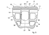
図5を用いて説明される実施形態によれば、内顆13および外顆14を骨に装着するために必要なアクリルセメントを搭載するために、内顆13および外顆14の内側部分に凹んだ面(また、表面凹み30と呼ばれる)を有することができる。
According to the embodiment described with reference to FIG. 5, the
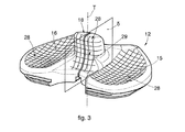
いくつかの実施形態において、脛骨インサート12は、装着時には内顆13および外顆14(図3および9)をそれぞれ支持する内側関節面15および外側関節面16を有する。
In some embodiments, the
脛骨インサート12は、装着時は顆間溝19に位置することができ、具体的には、カム17と干渉(接触)させることが可能な脛骨ポスト18(以降、単にポスト18)を備える。
The
内側関節面15と、外側関節面16と、ポスト18の後部面29とが全体で、大腿骨コンポーネント11を備える脛骨関節面28を実現する。
The inner
脛骨インサート12はまた、実質的に公知な方法で、底面(ベース面)42(前述の脛骨プレートに適合する)を備える。
The
カム17の遠位面20は、脚を屈曲した際の既定の角度で、ポスト18と接触するよう構成される。
The
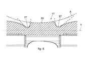
遠位面20はドラム形状(樽形)である。そして、その中央は、図5および6に示すように、半径R1の弧Aが定める凹面を有する(図2において容易に確認できる)。
The
具体的には、大腿骨中心面αに対して垂直なカム17の中心軸線Yの周りに、円の弧Aを回転させることによりドラム形状が定まる。
Specifically, the drum shape is determined by rotating a circular arc A around the central axis Y of the
弧Aの中心は、内側面β上にあり、その面は大腿骨中心面αに平行であるが、大腿骨中心面αと一致しない面であり、大腿骨中心面αと弧Aとの交差点と、弧Aの中心点とを結ぶ線が、大腿骨中心面αに対してなす角度γで定まる距離だけ離れている。 The center of the arc A is on the inner side surface β, and the plane is parallel to the femoral central plane α but is not coincident with the femoral central plane α, and the intersection of the femoral central plane α and the arc A And a line connecting the center point of the arc A are separated by a distance determined by an angle γ formed with respect to the femur central plane α.
考えられる実施では、角度γは、1°〜6°、好ましくは2°〜5°、より好ましくは、約3°であることができる。 In possible implementations, the angle γ can be 1 ° to 6 °, preferably 2 ° to 5 °, more preferably about 3 °.
具体的には、このように定められる角度γは、脚が屈曲する際の、外旋角度の平均値にも対応する。 Specifically, the angle γ thus determined also corresponds to the average value of the external rotation angle when the leg is bent.
外旋角度とは、脛骨中心面δ上にある縦軸Tに対して垂直な平面に投影された大腿骨カム17の中心軸線Yと、脛骨インサート12の内外軸Xとが成す角度を意味する。従って、内外軸Xは、脛骨インサート12の脛骨中心面δに対して垂直な軸である。
The external rotation angle means an angle formed by the central axis Y of the
遠位面20の中心は外顆14より、内顆13に近い。そして、これにより、遠位面20の最大内側直径は、遠位面20の最大外側直径より小さくなる。
The center of the
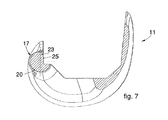
図7および8の実施例の形で、カム17の近位面23(特別機能を有さない)は、カム17の厚みを低減するために、よりアーチ状に湾曲した面を有することができる。
In the form of the embodiment of FIGS. 7 and 8, the
事実、カム17の近位面23は、大腿骨コンポーネント11および脛骨インサート12の屈曲がどんな角度であっても、ポスト18と接触せず、したがって、特に機能することがない。
In fact, the
具体的には、図7および8に示すように、破線Bは、軸Yを中心とする円弧Aの回転の続きであり、曲率が変化する位置24から離れていく。
Specifically, as shown in FIGS. 7 and 8, the broken line B is a continuation of the rotation of the arc A around the axis Y and moves away from the
近位面23は、L字状の接続面25によって切り取られ、そして、大腿骨コンポーネント11の内部凹面26の方に向けて配置される。
The
大腿骨コンポーネント11の後側部分のカム17の位置は、具体的には、ポスト18との耐性およびジャンプ・ディスタンス(jump distance)Jに対して有利である。
The position of the
専門用語「ジャンプ・ディスタンス」とは、大腿骨コンポーネント11のカム17がポスト18の最も高い位置を通過できるように、大腿骨コンポーネント11のカム17が垂直に移動しなければならない最小の距離を意味する。
The term “jump distance” means the minimum distance that the
従って、ジャンプ・ディスタンスJは、顆間溝19に対するカム17の相対的な位置と関節面15および16からのポスト18の高さによって確定する。
Accordingly, the jump distance J is determined by the relative position of the
図5および6による実施形態において、内顆13および外顆14にそれぞれ接続する、2つのスリット27が、カム17の後部内側部分と後部外側部分にある。
In the embodiment according to FIGS. 5 and 6, there are two
切れ込み27が無くカム17が続くと、脛骨関節面28と顆13と14との間の相互作用に影響しうる。
If the
図9に示すように、ポスト18の断面は実質的に矩形の形状であり、ポスト18は脛骨中心面δに対して対称である。
As shown in FIG. 9, the
ポスト18の後部面29は、装着の間、カム17と接触する表面に対応する。
The
後部面29は、脛骨インサート12の底面42と平行な平面にある、アキシャル(体軸断面)曲率半径R2を有する。
The
本発明のいくつかの実施例によれば、後部面29の半径R2(脛骨インサート12の底面42と平行な面にある)は、実質的に弧Aの半径R1の半分である(図4および図9参照)。
According to some embodiments of the present invention, the radius R2 of the posterior surface 29 (in a plane parallel to the
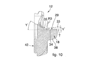
ポスト18の外側断面においては、図10に示すように、後部面29は、近位部分33と、中心部34と、遠位部分35とを備える。
In the outer cross section of the
中心部34は、カム17の遠位面20のサジタル(矢状断面)曲率半径R4より大きいサジタル半径R3で作られる(図8および図10参照)。
The
考えられる実施では、半径R3と半径R4間の比率は、例として、10%〜50%、好ましくは25%〜35%である。 In possible implementations, the ratio between radius R3 and radius R4 is, by way of example, 10% to 50%, preferably 25% to 35%.
いくつかの実施形態によると、ポスト18とカム17との接触は、脛骨に対する腿骨の屈曲角度が約120°までは、中心部34の内側である。
According to some embodiments, the contact between the
図10を用いて記載される実施形態において、遠位部分35は、垂直軸Tに対して角度γ’だけ傾けられる。
In the embodiment described using FIG. 10, the
考えられる実施では、角度γ’は、約25°から55°まで、好ましくは約20°から40°まで、より好ましくは、約30°であることができる。 In possible implementations, the angle γ 'can be about 25 ° to 55 °, preferably about 20 ° to 40 °, more preferably about 30 °.
図8の実施例による実施形態において、近位部分33は、垂直軸Tに対して角度γ”だけ傾けられる。
In the embodiment according to the example of FIG. 8, the
考えられる実施では、角度γ”は、約3°から20°までの範囲、好ましくは約5°から15°まで、より好ましくは、約10°であることができる。 In possible implementations, the angle γ ″ can range from about 3 ° to 20 °, preferably from about 5 ° to 15 °, more preferably about 10 °.
ポスト18とカム17との全接触軌跡に沿って、水平半径R2は、全屈曲運動に対して同様の接触構成となるようにする。
Along the entire contact locus between the
ポスト18とカム17との接点が変化するので、屈曲の異なる角度および脚の回転の異なる角度に対して、半径R1、R2、R3、R4は一定のままである。
Because the contact point between the
このようにして、大腿骨カム17およびポスト18の接触面は、常に同様になる。
In this way, the contact surfaces of the
いくつかの実施形態によれば、ポスト18は正面側に面(前面36と呼ぶ)を備え、それは、顆間溝19の前端部37と実質的に合致する。
According to some embodiments, the
具体的には、前面36および前端部37は、人工関節10の考えられる過伸展の際に、すなわち、脛骨が屈曲と反対側の運動を行い、それらの面が接触する最大の過伸展角度に到達する(図1で示す)ときに、接触する。
Specifically, the
脛骨インサート12の前面36は、過伸展する大腿骨コンポーネント11の前端部37と合致するよう構成される。このようにして、考えられる何らかの過伸展が生じた場合も、ポスト18の正面の損傷はいずれも防止される。
The
考えられる実施では、過伸展の最大角度は、約3°から9°まで、好ましくは約5°から8°まで、より好ましくは約7°である。 In possible implementations, the maximum angle of overextension is from about 3 ° to 9 °, preferably from about 5 ° to 8 °, more preferably about 7 °.
脛骨に対する大腿骨の特定の屈曲角度を過ぎたときだけ、通常、ポスト18およびカム17は接触する。
Normally, the
考えられる実施では、脛骨ポスト18と大腿骨カム17との間で最初に接触が生じる屈曲角度は、約60°から110°まで、好ましくは約80°から90°まで、より好ましくは約85°である。
In possible implementations, the bending angle at which contact first occurs between the
脛骨ポスト18と大腿骨カム17との接触が始まる屈曲角度は、大腿骨コンポーネント11と脛骨インサート12間の最初の位置関係と、靭帯の状況と、大腿骨と脛骨の間で生じる動きと、に完全に依存する。
The flexion angle at which contact between the
特に、屈曲運動に加えて同時に大腿骨および脛骨の回転もある場合、脛骨ポスト18と大腿骨カム17とが最初に接触する屈曲角度は、変化しうる。
In particular, if there is also rotation of the femur and tibia at the same time as the flexion movement, the flexion angle at which the
図11および12は、大腿骨と脛骨との屈曲角度が90°および120°であるときの、ポスト18とカム17とが接触する状態をそれぞれ示す。
11 and 12 show the state in which the
図11および12の両状態に対して、ポスト18とカム17との接触点は、ポスト18の後部面29のおおよそ中心部34にある。
11 and 12, the point of contact between the
図11および12にある様に、ポスト18とカム17間の接点において、下および前方向の加圧軸Zに沿って、直接力が加えられる。
As shown in FIGS. 11 and 12, a force is applied directly along the downward and forward pressure axis Z at the contact point between the
いくつかの実施形態によれば、ポスト18およびカム17は、大腿骨および脛骨が屈曲する間、カム17の遠位面20とポスト18の後部面29の間の接触面が、考え得る最大になるように作製される。
According to some embodiments, the
図13〜16は、具体的には、90°の屈曲の4つの状況を示す。そして、大腿骨および脛骨の異なる外旋角度に対応する。図13、14、15、16は、それぞれ0°、3°、6°および10°の外旋角度に対応する。 FIGS. 13-16 specifically show four situations of 90 ° bending. It corresponds to different external rotation angles of the femur and tibia. 13, 14, 15, and 16 correspond to external rotation angles of 0 °, 3 °, 6 °, and 10 °, respectively.
図14に示すように、3°の外旋角度では、ポスト18の後部面29と、カム17の遠位面20間の接触形状は、前記表面両方の中心接触点に対し相補的である。
As shown in FIG. 14, at an external rotation angle of 3 °, the contact shape between the
図13、14、15に示す構成において、接触面はポスト18の後部面29上に留まり、そして、ぴったりと合致しない形状は、過剰な負荷でポスト18の端に応力がかかるのを防ぐ。
In the configuration shown in FIGS. 13, 14, and 15, the contact surface remains on the
このようにして、損傷を与えうる圧力が、ポスト18の端で発生することはない。
In this way, no damaging pressure is generated at the end of the
大腿骨コンポーネント11のカム17の後部位置により、大腿骨および脛骨のすべての屈曲に対して、低い(すなわち底面42方向に向かう)位置でカム17とポスト18とが接触する。
The posterior position of the
大腿骨カム17との接触に関して、ポスト18のその領域が、適切な機械耐性を生じるだけでなく、前記耐性は、脛骨インサート12の領域からの寄与もあるため、この構成は有利である(図11、12を参照)。事実、接点に対応して、その領域の面積は、脛骨ポスト18に対するだけでなく、脛骨インサート12の前部に対するものであり、より大きな耐久面を実現する。
With respect to contact with the
他の有利な本発明の特徴は、接触時に大腿骨カム17が脛骨ポスト18に伝達する力の方向であり、それは、すべての屈曲角度に対して、下方および前方に向かう。接触の力が下および前方向なので、移植の際に機械的に装着される脛骨プレートから脛骨インサート12が分離する危険率を低下させる。これは、下方向の接触の力が、脛骨インサート12および脛骨プレートの結合の安定性を向上させる圧力を発生させるからである。
Another advantageous feature of the present invention is the direction of force that the
ここまで述べた人工膝関節に対して、本発明の分野及び範囲から逸脱することなく各部の修正及び/又は追加を行うことができることは明らかである。 It will be apparent that modifications and / or additions can be made to the knee prosthesis described so far without departing from the scope and scope of the present invention.
いくつかの具体例を参照して本発明を説明したが、請求項に記載の特徴を有し、それ故、全てそこに定められる保護範囲内となる、人工膝関節の多くの他の同等の形状を当業者が達成することが確実に可能であることは明白でもある。 Although the present invention has been described with reference to several specific examples, many other equivalents of knee prostheses have the features recited in the claims and therefore are all within the scope of protection defined therein. It is also clear that the shape can certainly be achieved by those skilled in the art.
Claims (9)
前記人工膝関節は、大腿骨の遠位端に取り付けることが可能な大腿骨コンポーネント(11)を備え、
前記大腿骨コンポーネント(11)は、内顆(13)と、外顆(14)と、前壁(50)とを有し、
前記内顆(13)および前記外顆(14)は、顆間溝(19)の後部に近接して大腿骨カム(17)により結合され、前記内顆(13)および前記外顆(14)から延長する残りの部分にある前記顆間溝(19)で仕切られ、
前記人工膝関節はまた、脛骨の近位端へ装着するための脛骨コンポーネントを備え、
前記脛骨コンポーネントは、脛骨プレートおよび脛骨インサート(12)を備え、
前記脛骨インサート(12)は、前記内顆(13)を支持する内側関節面(15)と、 前記外顆(14)を支持する外側関節面(16)と、実質的に前記脛骨インサート(12)の長手方向の中心に配置される脛骨ポスト(18)とを備え、
前記大腿骨カム(17)は非対称で、そして、前記脛骨ポスト(18)で関節接合するドラム形状の遠位面(20)を備えることを特徴とする、人工膝関節。 An artificial knee joint,
The knee prosthesis comprises a femoral component (11) that can be attached to the distal end of the femur;
The femoral component (11) has an internal condyle (13), an external condyle (14), and an anterior wall (50);
The inner condyle (13) and the outer condyle (14) are joined by a femoral cam (17) proximate to the posterior part of the intercondylar groove (19), and the inner condyle (13) and the outer condyle (14). Partitioned by the intercondylar groove (19) in the remaining part extending from
The knee prosthesis also includes a tibial component for attachment to the proximal end of the tibia,
The tibial component comprises a tibial plate and a tibial insert (12);
The tibial insert (12) includes an inner articular surface (15) that supports the inner condyle (13), an outer articular surface (16) that supports the outer condyle (14), and substantially the tibial insert (12). A tibial post (18) disposed in the longitudinal center of
Knee prosthesis characterized in that the femoral cam (17) is asymmetric and comprises a drum-shaped distal surface (20) articulating with the tibial post (18).
前記遠位面(20)の最大内側直径が、前記遠位面(20)の最大外側直径より小さくなることを特徴とする、請求項1に記載の人工膝関節。 The center of the distal surface (20) is closer to the internal condyle (13) than the external condyle (14),
The knee prosthesis according to claim 1, characterized in that the maximum inner diameter of the distal surface (20) is smaller than the maximum outer diameter of the distal surface (20).
前記力は、下および前方向であることを特徴とする、
請求項1乃至4のいずれか一項記載の人工膝関節。 At least one contact point is determined by the tibial post (18) and the femoral cam (17), and a direct force is applied to the contact point along the pressure axis (Z),
The force is downward and forward,
The artificial knee joint according to any one of claims 1 to 4.
前記半径(R2)は実質的に前記弧(A)の前記半径(R1)の半分であることを特徴とする、請求項4に記載の人工膝関節。 The tibial post (18) comprises a posterior surface (29) having a radius (R2) in a plane parallel to the bottom surface (42) of the tibial insert (12);
The knee prosthesis according to claim 4, characterized in that the radius (R2) is substantially half the radius (R1) of the arc (A).
Applications Claiming Priority (3)
| Application Number | Priority Date | Filing Date | Title |
|---|---|---|---|
| ITUD20140023 | 2014-02-10 | ||
| ITUD2014A000023 | 2014-02-10 | ||
| PCT/IB2015/050997 WO2015118517A1 (en) | 2014-02-10 | 2015-02-10 | Artificial knee joint |
Publications (2)
| Publication Number | Publication Date |
|---|---|
| JP2017505214A true JP2017505214A (en) | 2017-02-16 |
| JP6499674B2 JP6499674B2 (en) | 2019-04-10 |
Family
ID=50342447
Family Applications (1)
| Application Number | Title | Priority Date | Filing Date |
|---|---|---|---|
| JP2016568159A Active JP6499674B2 (en) | 2014-02-10 | 2015-02-10 | Artificial knee joint |
Country Status (7)
| Country | Link |
|---|---|
| US (1) | US10045853B2 (en) |
| EP (1) | EP3104813B1 (en) |
| JP (1) | JP6499674B2 (en) |
| AU (1) | AU2015213574B2 (en) |
| BR (1) | BR112016018337B1 (en) |
| ES (1) | ES2686902T3 (en) |
| WO (1) | WO2015118517A1 (en) |
Families Citing this family (6)
| Publication number | Priority date | Publication date | Assignee | Title |
|---|---|---|---|---|
| US10179052B2 (en) * | 2016-07-28 | 2019-01-15 | Depuy Ireland Unlimited Company | Total knee implant prosthesis assembly and method |
| CN107616859A (en) * | 2017-10-18 | 2018-01-23 | 北京爱康宜诚医疗器材有限公司 | Single condyle knee-joint prosthesis |
| EP3698761B1 (en) | 2019-02-22 | 2021-11-17 | Stryker European Operations Limited | Total ankle prosthesis |
| CN113631123A (en) * | 2019-04-11 | 2021-11-09 | 帝人中岛医疗株式会社 | Artificial knee joint |
| US11382757B1 (en) * | 2020-01-15 | 2022-07-12 | Lento Medical, Inc. | Condylar asymmetry knee prosthesis |
| US11357634B1 (en) * | 2020-01-15 | 2022-06-14 | Lento Medical, Inc. | Posterior-stabilized symmetric knee prosthesis |
Citations (5)
| Publication number | Priority date | Publication date | Assignee | Title |
|---|---|---|---|---|
| JP2005261538A (en) * | 2004-03-17 | 2005-09-29 | Toru Suguro | Artificial knee joint |
| JP2010012256A (en) * | 2008-06-30 | 2010-01-21 | Depuy Products Inc | Posterior stabilized orthopaedic prosthesis |
| JP2010012255A (en) * | 2008-06-30 | 2010-01-21 | Depuy Products Inc | Posterior stabilized orthopaedic knee prosthesis having controlled condylar curvature |
| JP2011528235A (en) * | 2008-02-18 | 2011-11-17 | マックス オーソピディックス、インク. | Total replacement artificial knee joint with higher-order NURBS curved surface |
| KR20120124927A (en) * | 2011-05-06 | 2012-11-14 | 주식회사 코리아본뱅크 | post-cam structure of artficial knee joints |
Family Cites Families (9)
| Publication number | Priority date | Publication date | Assignee | Title |
|---|---|---|---|---|
| US5549686A (en) | 1994-06-06 | 1996-08-27 | Zimmer, Inc. | Knee prosthesis having a tapered cam |
| US5964808A (en) | 1996-07-11 | 1999-10-12 | Wright Medical Technology, Inc. | Knee prosthesis |
| US6123729A (en) | 1998-03-10 | 2000-09-26 | Bristol-Myers Squibb Company | Four compartment knee |
| US8292964B2 (en) | 2005-12-14 | 2012-10-23 | New York University | Surface guided knee replacement |
| JP5663118B2 (en) * | 2008-02-18 | 2015-02-04 | マックス オーソピディックス、インク. | Total replacement artificial knee joint with higher-order NURBS curved surface |
| US8491662B2 (en) | 2008-12-23 | 2013-07-23 | Aesculap Ag | Knee prosthesis |
| US20100161067A1 (en) | 2008-12-23 | 2010-06-24 | Aesculap Ag | Knee prosthesis |
| ES2443827T3 (en) * | 2010-10-05 | 2014-02-20 | Aesculap Ag | Knee Joint Endoprosthesis |
| CN103126787B (en) * | 2011-11-28 | 2015-03-04 | 北京纳通科技集团有限公司 | Knee-joint prosthesis |
-
2015
- 2015-02-10 JP JP2016568159A patent/JP6499674B2/en active Active
- 2015-02-10 ES ES15711831.6T patent/ES2686902T3/en active Active
- 2015-02-10 BR BR112016018337-1A patent/BR112016018337B1/en active IP Right Grant
- 2015-02-10 AU AU2015213574A patent/AU2015213574B2/en active Active
- 2015-02-10 EP EP15711831.6A patent/EP3104813B1/en active Active
- 2015-02-10 WO PCT/IB2015/050997 patent/WO2015118517A1/en active Application Filing
- 2015-02-10 US US15/117,358 patent/US10045853B2/en active Active
Patent Citations (5)
| Publication number | Priority date | Publication date | Assignee | Title |
|---|---|---|---|---|
| JP2005261538A (en) * | 2004-03-17 | 2005-09-29 | Toru Suguro | Artificial knee joint |
| JP2011528235A (en) * | 2008-02-18 | 2011-11-17 | マックス オーソピディックス、インク. | Total replacement artificial knee joint with higher-order NURBS curved surface |
| JP2010012256A (en) * | 2008-06-30 | 2010-01-21 | Depuy Products Inc | Posterior stabilized orthopaedic prosthesis |
| JP2010012255A (en) * | 2008-06-30 | 2010-01-21 | Depuy Products Inc | Posterior stabilized orthopaedic knee prosthesis having controlled condylar curvature |
| KR20120124927A (en) * | 2011-05-06 | 2012-11-14 | 주식회사 코리아본뱅크 | post-cam structure of artficial knee joints |
Also Published As
| Publication number | Publication date |
|---|---|
| BR112016018337B1 (en) | 2022-05-10 |
| EP3104813A1 (en) | 2016-12-21 |
| EP3104813B1 (en) | 2018-07-25 |
| US10045853B2 (en) | 2018-08-14 |
| WO2015118517A1 (en) | 2015-08-13 |
| BR112016018337A2 (en) | 2017-08-08 |
| AU2015213574A1 (en) | 2016-09-15 |
| ES2686902T3 (en) | 2018-10-22 |
| ES2686902T8 (en) | 2019-01-18 |
| US20170007415A1 (en) | 2017-01-12 |
| JP6499674B2 (en) | 2019-04-10 |
| AU2015213574B2 (en) | 2019-08-01 |
Similar Documents
| Publication | Publication Date | Title |
|---|---|---|
| JP6499674B2 (en) | Artificial knee joint | |
| JP6200559B2 (en) | Tibial support component for artificial knee joints with superior occlusal properties | |
| JP5208116B2 (en) | Posterior stable knee prosthesis | |
| JP4476548B2 (en) | Artificial knee joint | |
| US7815684B2 (en) | Knee prosthesis | |
| US7485147B2 (en) | Ankle prosthesis including tibial component having peripheral wall for preventing the formation of bone cysts | |
| JP5726851B2 (en) | Artificial knee joint | |
| JP6309231B2 (en) | Knee prosthesis system with standard and distal offset joint lines | |
| JPH05184612A (en) | Artificial joint with which natural joint is replaced, particularly artificial knee joint | |
| JP2010012256A (en) | Posterior stabilized orthopaedic prosthesis | |
| JP2000051252A (en) | Freely rotatable and movable articular prosthesis stabilized backward | |
| US20130190884A1 (en) | Artificial knee joint | |
| JP2018015571A (en) | Total Knee Implant Prosthesis Assembly and Method | |
| US9820855B2 (en) | Prosthesis and method for using prosthesis to facilitate deep knee flexion | |
| US20210177610A1 (en) | Femoral Component | |
| US20220175542A1 (en) | Orthopaedic system with insert having a post for medial pivoting of a femoral component | |
| JP7375026B2 (en) | artificial knee joint | |
| US20230130743A1 (en) | Artificial Ankle Joint Bearing Element | |
| JP6305268B2 (en) | Artificial knee joint | |
| JP2018023811A (en) | Artificial knee joint |
Legal Events
| Date | Code | Title | Description |
|---|---|---|---|
| A621 | Written request for application examination |
Free format text: JAPANESE INTERMEDIATE CODE: A621 Effective date: 20180119 |
|
| A977 | Report on retrieval |
Free format text: JAPANESE INTERMEDIATE CODE: A971007 Effective date: 20181026 |
|
| A131 | Notification of reasons for refusal |
Free format text: JAPANESE INTERMEDIATE CODE: A131 Effective date: 20181113 |
|
| A521 | Request for written amendment filed |
Free format text: JAPANESE INTERMEDIATE CODE: A523 Effective date: 20190205 |
|
| TRDD | Decision of grant or rejection written | ||
| A01 | Written decision to grant a patent or to grant a registration (utility model) |
Free format text: JAPANESE INTERMEDIATE CODE: A01 Effective date: 20190226 |
|
| A61 | First payment of annual fees (during grant procedure) |
Free format text: JAPANESE INTERMEDIATE CODE: A61 Effective date: 20190315 |
|
| R150 | Certificate of patent or registration of utility model |
Ref document number: 6499674 Country of ref document: JP Free format text: JAPANESE INTERMEDIATE CODE: R150 |
|
| R250 | Receipt of annual fees |
Free format text: JAPANESE INTERMEDIATE CODE: R250 |
|
| R250 | Receipt of annual fees |
Free format text: JAPANESE INTERMEDIATE CODE: R250 |
|
| R250 | Receipt of annual fees |
Free format text: JAPANESE INTERMEDIATE CODE: R250 |