JP2017503576A - Monitoring neuromuscular blockade - Google Patents
Monitoring neuromuscular blockade Download PDFInfo
- Publication number
- JP2017503576A JP2017503576A JP2016542708A JP2016542708A JP2017503576A JP 2017503576 A JP2017503576 A JP 2017503576A JP 2016542708 A JP2016542708 A JP 2016542708A JP 2016542708 A JP2016542708 A JP 2016542708A JP 2017503576 A JP2017503576 A JP 2017503576A
- Authority
- JP
- Japan
- Prior art keywords
- pulse
- electrical stimulation
- state
- pressure
- tof
- Prior art date
- Legal status (The legal status is an assumption and is not a legal conclusion. Google has not performed a legal analysis and makes no representation as to the accuracy of the status listed.)
- Granted
Links
- 206010029315 Neuromuscular blockade Diseases 0.000 title claims abstract description 71
- 238000012544 monitoring process Methods 0.000 title description 11
- 230000000638 stimulation Effects 0.000 claims abstract description 405
- 238000000034 method Methods 0.000 claims abstract description 274
- 210000003205 muscle Anatomy 0.000 claims abstract description 146
- 230000004044 response Effects 0.000 claims description 153
- 238000012795 verification Methods 0.000 claims description 121
- 230000002232 neuromuscular Effects 0.000 claims description 82
- 210000005036 nerve Anatomy 0.000 claims description 70
- 230000000903 blocking effect Effects 0.000 claims description 55
- 229920001169 thermoplastic Polymers 0.000 claims description 47
- 230000008569 process Effects 0.000 claims description 46
- 239000000835 fiber Substances 0.000 claims description 44
- 238000003466 welding Methods 0.000 claims description 29
- 230000002093 peripheral effect Effects 0.000 claims description 27
- 238000006243 chemical reaction Methods 0.000 claims description 25
- 239000002245 particle Substances 0.000 claims description 19
- 238000003475 lamination Methods 0.000 claims description 15
- 230000001960 triggered effect Effects 0.000 claims description 15
- 239000002184 metal Substances 0.000 claims description 13
- 229910052751 metal Inorganic materials 0.000 claims description 13
- 239000003158 myorelaxant agent Substances 0.000 claims description 13
- 230000005611 electricity Effects 0.000 claims description 10
- 239000004020 conductor Substances 0.000 claims description 8
- 229920001778 nylon Polymers 0.000 claims description 8
- 239000004677 Nylon Substances 0.000 claims description 7
- 239000004433 Thermoplastic polyurethane Substances 0.000 claims description 6
- 229920001940 conductive polymer Polymers 0.000 claims description 6
- 230000036461 convulsion Effects 0.000 claims description 6
- 229920002803 thermoplastic polyurethane Polymers 0.000 claims description 6
- 239000002131 composite material Substances 0.000 claims description 5
- 239000007788 liquid Substances 0.000 claims description 5
- 239000000123 paper Substances 0.000 claims description 5
- 229920000049 Carbon (fiber) Polymers 0.000 claims description 4
- 239000004917 carbon fiber Substances 0.000 claims description 4
- 239000000428 dust Substances 0.000 claims description 4
- OKTJSMMVPCPJKN-UHFFFAOYSA-N Carbon Chemical compound [C] OKTJSMMVPCPJKN-UHFFFAOYSA-N 0.000 claims description 3
- 229910002804 graphite Inorganic materials 0.000 claims description 3
- 239000010439 graphite Substances 0.000 claims description 3
- 239000004745 nonwoven fabric Substances 0.000 claims description 3
- 229920002635 polyurethane Polymers 0.000 claims description 3
- 239000004814 polyurethane Substances 0.000 claims description 3
- 239000004800 polyvinyl chloride Substances 0.000 claims description 3
- 230000000295 complement effect Effects 0.000 claims description 2
- 230000001939 inductive effect Effects 0.000 claims description 2
- 230000033001 locomotion Effects 0.000 claims description 2
- VNWKTOKETHGBQD-UHFFFAOYSA-N methane Chemical compound C VNWKTOKETHGBQD-UHFFFAOYSA-N 0.000 claims description 2
- 238000009530 blood pressure measurement Methods 0.000 claims 8
- 230000003387 muscular Effects 0.000 claims 3
- 238000010292 electrical insulation Methods 0.000 claims 1
- 230000004936 stimulating effect Effects 0.000 abstract description 7
- 230000000875 corresponding effect Effects 0.000 description 35
- 230000008859 change Effects 0.000 description 17
- 238000004519 manufacturing process Methods 0.000 description 15
- 239000010408 film Substances 0.000 description 14
- 239000000758 substrate Substances 0.000 description 14
- 230000005540 biological transmission Effects 0.000 description 13
- 238000012937 correction Methods 0.000 description 13
- 239000003814 drug Substances 0.000 description 13
- 229940079593 drug Drugs 0.000 description 13
- 238000009795 derivation Methods 0.000 description 12
- 230000007704 transition Effects 0.000 description 12
- 230000000763 evoking effect Effects 0.000 description 11
- 238000001356 surgical procedure Methods 0.000 description 11
- 239000000853 adhesive Substances 0.000 description 9
- 230000001070 adhesive effect Effects 0.000 description 9
- 239000000463 material Substances 0.000 description 9
- 239000012528 membrane Substances 0.000 description 8
- 230000005684 electric field Effects 0.000 description 6
- 230000002102 hyperpolarization Effects 0.000 description 6
- 230000001965 increasing effect Effects 0.000 description 6
- 238000007639 printing Methods 0.000 description 6
- 238000005304 joining Methods 0.000 description 5
- 230000010004 neural pathway Effects 0.000 description 5
- 210000000118 neural pathway Anatomy 0.000 description 5
- 238000012546 transfer Methods 0.000 description 5
- 230000018405 transmission of nerve impulse Effects 0.000 description 5
- 230000006378 damage Effects 0.000 description 4
- 238000000151 deposition Methods 0.000 description 4
- 230000008021 deposition Effects 0.000 description 4
- 230000000694 effects Effects 0.000 description 4
- 230000006870 function Effects 0.000 description 4
- 238000011084 recovery Methods 0.000 description 4
- 239000000126 substance Substances 0.000 description 4
- 230000008901 benefit Effects 0.000 description 3
- 230000008878 coupling Effects 0.000 description 3
- 238000010168 coupling process Methods 0.000 description 3
- 238000005859 coupling reaction Methods 0.000 description 3
- 238000010030 laminating Methods 0.000 description 3
- 239000000615 nonconductor Substances 0.000 description 3
- 230000037361 pathway Effects 0.000 description 3
- 239000000565 sealant Substances 0.000 description 3
- 238000012360 testing method Methods 0.000 description 3
- 239000010409 thin film Substances 0.000 description 3
- 206010061218 Inflammation Diseases 0.000 description 2
- 208000027418 Wounds and injury Diseases 0.000 description 2
- 230000009471 action Effects 0.000 description 2
- 230000004913 activation Effects 0.000 description 2
- 230000004888 barrier function Effects 0.000 description 2
- 210000002302 brachial artery Anatomy 0.000 description 2
- 239000003795 chemical substances by application Substances 0.000 description 2
- 230000006835 compression Effects 0.000 description 2
- 238000007906 compression Methods 0.000 description 2
- 238000001514 detection method Methods 0.000 description 2
- 238000009826 distribution Methods 0.000 description 2
- 230000004907 flux Effects 0.000 description 2
- 238000002695 general anesthesia Methods 0.000 description 2
- 238000010438 heat treatment Methods 0.000 description 2
- 230000001976 improved effect Effects 0.000 description 2
- 230000004054 inflammatory process Effects 0.000 description 2
- 208000014674 injury Diseases 0.000 description 2
- 229940035363 muscle relaxants Drugs 0.000 description 2
- 230000007433 nerve pathway Effects 0.000 description 2
- 239000002547 new drug Substances 0.000 description 2
- 238000010561 standard procedure Methods 0.000 description 2
- 210000000658 ulnar nerve Anatomy 0.000 description 2
- 238000007740 vapor deposition Methods 0.000 description 2
- 239000011800 void material Substances 0.000 description 2
- RYGMFSIKBFXOCR-UHFFFAOYSA-N Copper Chemical compound [Cu] RYGMFSIKBFXOCR-UHFFFAOYSA-N 0.000 description 1
- 201000004624 Dermatitis Diseases 0.000 description 1
- 206010021118 Hypotonia Diseases 0.000 description 1
- 208000034693 Laceration Diseases 0.000 description 1
- 208000008238 Muscle Spasticity Diseases 0.000 description 1
- 206010040880 Skin irritation Diseases 0.000 description 1
- 229920002370 Sugammadex Polymers 0.000 description 1
- 230000001133 acceleration Effects 0.000 description 1
- 230000003213 activating effect Effects 0.000 description 1
- 230000004872 arterial blood pressure Effects 0.000 description 1
- 239000012298 atmosphere Substances 0.000 description 1
- 238000004590 computer program Methods 0.000 description 1
- 238000010276 construction Methods 0.000 description 1
- 229910052802 copper Inorganic materials 0.000 description 1
- 239000010949 copper Substances 0.000 description 1
- 238000013479 data entry Methods 0.000 description 1
- 230000002950 deficient Effects 0.000 description 1
- 230000001934 delay Effects 0.000 description 1
- 230000001419 dependent effect Effects 0.000 description 1
- 238000003745 diagnosis Methods 0.000 description 1
- 238000010586 diagram Methods 0.000 description 1
- 238000001035 drying Methods 0.000 description 1
- 238000002474 experimental method Methods 0.000 description 1
- 238000001914 filtration Methods 0.000 description 1
- 230000005057 finger movement Effects 0.000 description 1
- -1 for example Polymers 0.000 description 1
- 230000006698 induction Effects 0.000 description 1
- 238000002347 injection Methods 0.000 description 1
- 239000007924 injection Substances 0.000 description 1
- 238000003780 insertion Methods 0.000 description 1
- 230000037431 insertion Effects 0.000 description 1
- 238000012423 maintenance Methods 0.000 description 1
- 239000011159 matrix material Substances 0.000 description 1
- 238000000691 measurement method Methods 0.000 description 1
- 238000002156 mixing Methods 0.000 description 1
- 230000004899 motility Effects 0.000 description 1
- 238000000465 moulding Methods 0.000 description 1
- 230000036640 muscle relaxation Effects 0.000 description 1
- 210000000715 neuromuscular junction Anatomy 0.000 description 1
- 210000002569 neuron Anatomy 0.000 description 1
- 239000008188 pellet Substances 0.000 description 1
- 230000035515 penetration Effects 0.000 description 1
- 230000000737 periodic effect Effects 0.000 description 1
- 229920003023 plastic Polymers 0.000 description 1
- 239000004033 plastic Substances 0.000 description 1
- 229920000642 polymer Polymers 0.000 description 1
- 229920001296 polysiloxane Polymers 0.000 description 1
- 238000003825 pressing Methods 0.000 description 1
- 230000003449 preventive effect Effects 0.000 description 1
- 238000004080 punching Methods 0.000 description 1
- 230000009467 reduction Effects 0.000 description 1
- 230000002441 reversible effect Effects 0.000 description 1
- 230000000630 rising effect Effects 0.000 description 1
- 238000007650 screen-printing Methods 0.000 description 1
- 230000001568 sexual effect Effects 0.000 description 1
- 230000008054 signal transmission Effects 0.000 description 1
- 230000036556 skin irritation Effects 0.000 description 1
- 231100000475 skin irritation Toxicity 0.000 description 1
- 239000000243 solution Substances 0.000 description 1
- 208000018198 spasticity Diseases 0.000 description 1
- 230000007480 spreading Effects 0.000 description 1
- 238000003892 spreading Methods 0.000 description 1
- WHRODDIHRRDWEW-VTHZAVIASA-N sugammadex Chemical compound O([C@@H]([C@@H]([C@H]1O)O)O[C@H]2[C@H](O)[C@H]([C@@H](O[C@@H]3[C@@H](CSCCC(O)=O)O[C@@H]([C@@H]([C@H]3O)O)O[C@@H]3[C@@H](CSCCC(O)=O)O[C@@H]([C@@H]([C@H]3O)O)O[C@@H]3[C@@H](CSCCC(O)=O)O[C@@H]([C@@H]([C@H]3O)O)O[C@@H]3[C@@H](CSCCC(O)=O)O[C@@H]([C@@H]([C@H]3O)O)O[C@@H]3[C@@H](CSCCC(O)=O)O[C@@H]([C@@H]([C@H]3O)O)O3)O[C@@H]2CSCCC(O)=O)O)[C@H](CSCCC(O)=O)[C@H]1O[C@@H]1[C@H](O)[C@@H](O)[C@H]3[C@@H](CSCCC(O)=O)O1 WHRODDIHRRDWEW-VTHZAVIASA-N 0.000 description 1
- 229960002257 sugammadex Drugs 0.000 description 1
- 230000001225 therapeutic effect Effects 0.000 description 1
- 239000004416 thermosoftening plastic Substances 0.000 description 1
- 238000002627 tracheal intubation Methods 0.000 description 1
- 210000000623 ulna Anatomy 0.000 description 1
- 238000011144 upstream manufacturing Methods 0.000 description 1
Images


Classifications
-
- A—HUMAN NECESSITIES
- A61—MEDICAL OR VETERINARY SCIENCE; HYGIENE
- A61B—DIAGNOSIS; SURGERY; IDENTIFICATION
- A61B5/00—Measuring for diagnostic purposes; Identification of persons
- A61B5/103—Detecting, measuring or recording devices for testing the shape, pattern, colour, size or movement of the body or parts thereof, for diagnostic purposes
- A61B5/11—Measuring movement of the entire body or parts thereof, e.g. head or hand tremor, mobility of a limb
- A61B5/1104—Measuring movement of the entire body or parts thereof, e.g. head or hand tremor, mobility of a limb induced by stimuli or drugs
- A61B5/1106—Measuring movement of the entire body or parts thereof, e.g. head or hand tremor, mobility of a limb induced by stimuli or drugs to assess neuromuscular blockade, e.g. to estimate depth of anaesthesia
-
- A—HUMAN NECESSITIES
- A61—MEDICAL OR VETERINARY SCIENCE; HYGIENE
- A61B—DIAGNOSIS; SURGERY; IDENTIFICATION
- A61B5/00—Measuring for diagnostic purposes; Identification of persons
- A61B5/02—Detecting, measuring or recording pulse, heart rate, blood pressure or blood flow; Combined pulse/heart-rate/blood pressure determination; Evaluating a cardiovascular condition not otherwise provided for, e.g. using combinations of techniques provided for in this group with electrocardiography or electroauscultation; Heart catheters for measuring blood pressure
- A61B5/021—Measuring pressure in heart or blood vessels
- A61B5/022—Measuring pressure in heart or blood vessels by applying pressure to close blood vessels, e.g. against the skin; Ophthalmodynamometers
- A61B5/02233—Occluders specially adapted therefor
-
- A—HUMAN NECESSITIES
- A61—MEDICAL OR VETERINARY SCIENCE; HYGIENE
- A61B—DIAGNOSIS; SURGERY; IDENTIFICATION
- A61B5/00—Measuring for diagnostic purposes; Identification of persons
- A61B5/05—Detecting, measuring or recording for diagnosis by means of electric currents or magnetic fields; Measuring using microwaves or radio waves
-
- A—HUMAN NECESSITIES
- A61—MEDICAL OR VETERINARY SCIENCE; HYGIENE
- A61B—DIAGNOSIS; SURGERY; IDENTIFICATION
- A61B5/00—Measuring for diagnostic purposes; Identification of persons
- A61B5/103—Detecting, measuring or recording devices for testing the shape, pattern, colour, size or movement of the body or parts thereof, for diagnostic purposes
- A61B5/11—Measuring movement of the entire body or parts thereof, e.g. head or hand tremor, mobility of a limb
- A61B5/1107—Measuring contraction of parts of the body, e.g. organ, muscle
-
- A—HUMAN NECESSITIES
- A61—MEDICAL OR VETERINARY SCIENCE; HYGIENE
- A61B—DIAGNOSIS; SURGERY; IDENTIFICATION
- A61B5/00—Measuring for diagnostic purposes; Identification of persons
- A61B5/24—Detecting, measuring or recording bioelectric or biomagnetic signals of the body or parts thereof
- A61B5/316—Modalities, i.e. specific diagnostic methods
- A61B5/389—Electromyography [EMG]
- A61B5/395—Details of stimulation, e.g. nerve stimulation to elicit EMG response
-
- A—HUMAN NECESSITIES
- A61—MEDICAL OR VETERINARY SCIENCE; HYGIENE
- A61B—DIAGNOSIS; SURGERY; IDENTIFICATION
- A61B5/00—Measuring for diagnostic purposes; Identification of persons
- A61B5/45—For evaluating or diagnosing the musculoskeletal system or teeth
- A61B5/4519—Muscles
-
- A—HUMAN NECESSITIES
- A61—MEDICAL OR VETERINARY SCIENCE; HYGIENE
- A61B—DIAGNOSIS; SURGERY; IDENTIFICATION
- A61B5/00—Measuring for diagnostic purposes; Identification of persons
- A61B5/48—Other medical applications
- A61B5/4821—Determining level or depth of anaesthesia
-
- A—HUMAN NECESSITIES
- A61—MEDICAL OR VETERINARY SCIENCE; HYGIENE
- A61B—DIAGNOSIS; SURGERY; IDENTIFICATION
- A61B5/00—Measuring for diagnostic purposes; Identification of persons
- A61B5/48—Other medical applications
- A61B5/4836—Diagnosis combined with treatment in closed-loop systems or methods
-
- A—HUMAN NECESSITIES
- A61—MEDICAL OR VETERINARY SCIENCE; HYGIENE
- A61B—DIAGNOSIS; SURGERY; IDENTIFICATION
- A61B5/00—Measuring for diagnostic purposes; Identification of persons
- A61B5/48—Other medical applications
- A61B5/4848—Monitoring or testing the effects of treatment, e.g. of medication
-
- A—HUMAN NECESSITIES
- A61—MEDICAL OR VETERINARY SCIENCE; HYGIENE
- A61B—DIAGNOSIS; SURGERY; IDENTIFICATION
- A61B5/00—Measuring for diagnostic purposes; Identification of persons
- A61B5/68—Arrangements of detecting, measuring or recording means, e.g. sensors, in relation to patient
- A61B5/6801—Arrangements of detecting, measuring or recording means, e.g. sensors, in relation to patient specially adapted to be attached to or worn on the body surface
- A61B5/6813—Specially adapted to be attached to a specific body part
- A61B5/6824—Arm or wrist
-
- A—HUMAN NECESSITIES
- A61—MEDICAL OR VETERINARY SCIENCE; HYGIENE
- A61B—DIAGNOSIS; SURGERY; IDENTIFICATION
- A61B5/00—Measuring for diagnostic purposes; Identification of persons
- A61B5/68—Arrangements of detecting, measuring or recording means, e.g. sensors, in relation to patient
- A61B5/6801—Arrangements of detecting, measuring or recording means, e.g. sensors, in relation to patient specially adapted to be attached to or worn on the body surface
- A61B5/6813—Specially adapted to be attached to a specific body part
- A61B5/6828—Leg
-
- A—HUMAN NECESSITIES
- A61—MEDICAL OR VETERINARY SCIENCE; HYGIENE
- A61B—DIAGNOSIS; SURGERY; IDENTIFICATION
- A61B5/00—Measuring for diagnostic purposes; Identification of persons
- A61B5/68—Arrangements of detecting, measuring or recording means, e.g. sensors, in relation to patient
- A61B5/6801—Arrangements of detecting, measuring or recording means, e.g. sensors, in relation to patient specially adapted to be attached to or worn on the body surface
- A61B5/683—Means for maintaining contact with the body
- A61B5/6831—Straps, bands or harnesses
-
- A—HUMAN NECESSITIES
- A61—MEDICAL OR VETERINARY SCIENCE; HYGIENE
- A61B—DIAGNOSIS; SURGERY; IDENTIFICATION
- A61B5/00—Measuring for diagnostic purposes; Identification of persons
- A61B5/72—Signal processing specially adapted for physiological signals or for diagnostic purposes
- A61B5/7203—Signal processing specially adapted for physiological signals or for diagnostic purposes for noise prevention, reduction or removal
-
- A—HUMAN NECESSITIES
- A61—MEDICAL OR VETERINARY SCIENCE; HYGIENE
- A61B—DIAGNOSIS; SURGERY; IDENTIFICATION
- A61B5/00—Measuring for diagnostic purposes; Identification of persons
- A61B5/72—Signal processing specially adapted for physiological signals or for diagnostic purposes
- A61B5/7271—Specific aspects of physiological measurement analysis
- A61B5/7275—Determining trends in physiological measurement data; Predicting development of a medical condition based on physiological measurements, e.g. determining a risk factor
-
- A—HUMAN NECESSITIES
- A61—MEDICAL OR VETERINARY SCIENCE; HYGIENE
- A61N—ELECTROTHERAPY; MAGNETOTHERAPY; RADIATION THERAPY; ULTRASOUND THERAPY
- A61N1/00—Electrotherapy; Circuits therefor
- A61N1/02—Details
- A61N1/04—Electrodes
- A61N1/0404—Electrodes for external use
- A61N1/0408—Use-related aspects
- A61N1/0452—Specially adapted for transcutaneous muscle stimulation [TMS]
-
- A—HUMAN NECESSITIES
- A61—MEDICAL OR VETERINARY SCIENCE; HYGIENE
- A61N—ELECTROTHERAPY; MAGNETOTHERAPY; RADIATION THERAPY; ULTRASOUND THERAPY
- A61N1/00—Electrotherapy; Circuits therefor
- A61N1/02—Details
- A61N1/04—Electrodes
- A61N1/0404—Electrodes for external use
- A61N1/0472—Structure-related aspects
- A61N1/0492—Patch electrodes
- A61N1/0496—Patch electrodes characterised by using specific chemical compositions, e.g. hydrogel compositions, adhesives
-
- A—HUMAN NECESSITIES
- A61—MEDICAL OR VETERINARY SCIENCE; HYGIENE
- A61N—ELECTROTHERAPY; MAGNETOTHERAPY; RADIATION THERAPY; ULTRASOUND THERAPY
- A61N1/00—Electrotherapy; Circuits therefor
- A61N1/02—Details
- A61N1/04—Electrodes
- A61N1/05—Electrodes for implantation or insertion into the body, e.g. heart electrode
- A61N1/0551—Spinal or peripheral nerve electrodes
- A61N1/0556—Cuff electrodes
-
- A—HUMAN NECESSITIES
- A61—MEDICAL OR VETERINARY SCIENCE; HYGIENE
- A61N—ELECTROTHERAPY; MAGNETOTHERAPY; RADIATION THERAPY; ULTRASOUND THERAPY
- A61N1/00—Electrotherapy; Circuits therefor
- A61N1/02—Details
- A61N1/04—Electrodes
- A61N1/05—Electrodes for implantation or insertion into the body, e.g. heart electrode
- A61N1/0551—Spinal or peripheral nerve electrodes
- A61N1/0558—Anchoring or fixation means therefor
-
- A—HUMAN NECESSITIES
- A61—MEDICAL OR VETERINARY SCIENCE; HYGIENE
- A61N—ELECTROTHERAPY; MAGNETOTHERAPY; RADIATION THERAPY; ULTRASOUND THERAPY
- A61N1/00—Electrotherapy; Circuits therefor
- A61N1/18—Applying electric currents by contact electrodes
- A61N1/32—Applying electric currents by contact electrodes alternating or intermittent currents
- A61N1/36—Applying electric currents by contact electrodes alternating or intermittent currents for stimulation
- A61N1/36003—Applying electric currents by contact electrodes alternating or intermittent currents for stimulation of motor muscles, e.g. for walking assistance
-
- A—HUMAN NECESSITIES
- A61—MEDICAL OR VETERINARY SCIENCE; HYGIENE
- A61N—ELECTROTHERAPY; MAGNETOTHERAPY; RADIATION THERAPY; ULTRASOUND THERAPY
- A61N1/00—Electrotherapy; Circuits therefor
- A61N1/18—Applying electric currents by contact electrodes
- A61N1/32—Applying electric currents by contact electrodes alternating or intermittent currents
- A61N1/36—Applying electric currents by contact electrodes alternating or intermittent currents for stimulation
- A61N1/36014—External stimulators, e.g. with patch electrodes
-
- A—HUMAN NECESSITIES
- A61—MEDICAL OR VETERINARY SCIENCE; HYGIENE
- A61B—DIAGNOSIS; SURGERY; IDENTIFICATION
- A61B2505/00—Evaluating, monitoring or diagnosing in the context of a particular type of medical care
- A61B2505/05—Surgical care
-
- A—HUMAN NECESSITIES
- A61—MEDICAL OR VETERINARY SCIENCE; HYGIENE
- A61B—DIAGNOSIS; SURGERY; IDENTIFICATION
- A61B2562/00—Details of sensors; Constructional details of sensor housings or probes; Accessories for sensors
- A61B2562/02—Details of sensors specially adapted for in-vivo measurements
- A61B2562/0219—Inertial sensors, e.g. accelerometers, gyroscopes, tilt switches
-
- A—HUMAN NECESSITIES
- A61—MEDICAL OR VETERINARY SCIENCE; HYGIENE
- A61B—DIAGNOSIS; SURGERY; IDENTIFICATION
- A61B2562/00—Details of sensors; Constructional details of sensor housings or probes; Accessories for sensors
- A61B2562/02—Details of sensors specially adapted for in-vivo measurements
- A61B2562/0247—Pressure sensors
-
- A—HUMAN NECESSITIES
- A61—MEDICAL OR VETERINARY SCIENCE; HYGIENE
- A61N—ELECTROTHERAPY; MAGNETOTHERAPY; RADIATION THERAPY; ULTRASOUND THERAPY
- A61N1/00—Electrotherapy; Circuits therefor
- A61N1/02—Details
- A61N1/04—Electrodes
- A61N1/0404—Electrodes for external use
- A61N1/0472—Structure-related aspects
- A61N1/0484—Garment electrodes worn by the patient
Landscapes
- Health & Medical Sciences (AREA)
- Life Sciences & Earth Sciences (AREA)
- Engineering & Computer Science (AREA)
- Veterinary Medicine (AREA)
- Public Health (AREA)
- General Health & Medical Sciences (AREA)
- Animal Behavior & Ethology (AREA)
- Biomedical Technology (AREA)
- Heart & Thoracic Surgery (AREA)
- Biophysics (AREA)
- Physics & Mathematics (AREA)
- Molecular Biology (AREA)
- Pathology (AREA)
- Surgery (AREA)
- Medical Informatics (AREA)
- Nuclear Medicine, Radiotherapy & Molecular Imaging (AREA)
- Radiology & Medical Imaging (AREA)
- Physiology (AREA)
- Cardiology (AREA)
- Dentistry (AREA)
- Neurology (AREA)
- Oral & Maxillofacial Surgery (AREA)
- Orthopedic Medicine & Surgery (AREA)
- Chemical & Material Sciences (AREA)
- Vascular Medicine (AREA)
- Neurosurgery (AREA)
- Signal Processing (AREA)
- Anesthesiology (AREA)
- Artificial Intelligence (AREA)
- Psychiatry (AREA)
- Computer Vision & Pattern Recognition (AREA)
- Bioinformatics & Cheminformatics (AREA)
- Medicinal Chemistry (AREA)
- Ophthalmology & Optometry (AREA)
- Physical Education & Sports Medicine (AREA)
- Chemical Kinetics & Catalysis (AREA)
- General Chemical & Material Sciences (AREA)
- Rheumatology (AREA)
- Electrotherapy Devices (AREA)
- Measurement And Recording Of Electrical Phenomena And Electrical Characteristics Of The Living Body (AREA)
Abstract
本開示は、神経筋遮断状態を判断するさまざまな方法およびそのような方法を実行するのに適切なシステムに関する。本開示は、さらに、任意選択的に、記載した方法の少なくともいくつかの状況における、患者の筋肉を刺激するための電気刺激電極に関する。本開示は、またさらに、記載した方法の少なくともいくつかの状況で使用することができる電気刺激カフで使用するためのハイブリッド空気信号コネクタに関する。本開示はまた、電気刺激のための圧力カフに適切な電極部分およびトラック部分を備える電気刺激回路、および患者の手足の周りに配置されるよう構成されて、能動的電気刺激電極と受動的電気刺激電極とを備える圧力カフに関する。これらの電気刺激回路および圧力カフはまた、記載した方法の少なくともいくつかの状況で使用することができる。The present disclosure relates to various methods for determining neuromuscular blockade and systems suitable for performing such methods. The present disclosure further relates to an electrical stimulation electrode for optionally stimulating a patient's muscle in at least some situations of the described method. The present disclosure still further relates to a hybrid air signal connector for use with an electrical stimulation cuff that can be used in at least some situations of the described method. The present disclosure also includes an electrical stimulation circuit comprising an electrode portion and a track portion suitable for a pressure cuff for electrical stimulation, and an active electrical stimulation electrode and passive electrical circuitry configured to be disposed about a patient's limb. The present invention relates to a pressure cuff including a stimulation electrode. These electrical stimulation circuits and pressure cuffs can also be used in at least some situations of the described method.
Description
本開示は、神経筋遮断状態を判断するさまざまな方法およびそのような方法を実行するのに適切なシステムに関する。 The present disclosure relates to various methods for determining neuromuscular blockade and systems suitable for performing such methods.
本開示は、さらに、任意選択的に、上記の方法の少なくともいくつかの状況における、患者の筋肉を刺激するための電気刺激電極に関する。 The present disclosure further optionally relates to an electrical stimulation electrode for stimulating a patient's muscle in at least some situations of the above method.
本開示は、またさらに、上記の方法の少なくともいくつかの状況で使用することができる電気刺激カフで使用するためのハイブリッド空気信号コネクタに関する。 The present disclosure still further relates to a hybrid air signal connector for use with an electrical stimulation cuff that can be used in at least some situations of the above method.
本開示はまた、電気刺激のための圧力カフに適切な電極部分およびトラック部分を備える電気刺激回路、および患者の手足の周りに配置されるよう構成されて、能動的電気刺激電極と受動的電気刺激電極とを備える圧力カフに関する。 The present disclosure also includes an electrical stimulation circuit comprising an electrode portion and a track portion suitable for a pressure cuff for electrical stimulation, and an active electrical stimulation electrode and passive electrical circuitry configured to be disposed about a patient's limb. The present invention relates to a pressure cuff including a stimulation electrode.
本開示全体を通じて、「神経筋遮断」について言及する。技術分野において、「神経筋遮断」はまた、「神経筋ブロック」(「neuromuscular block」又は「neuromuscular blockage」)などと呼ばれる可能性がある。したがって、本明細書で使用されるような「神経筋遮断」(「neuromuscular blockage」)という用語は、これらの用語をカバーする。 Throughout this disclosure, reference will be made to “neuromuscular blockade”. In the technical field, “neuromuscular block” may also be referred to as “neuromuscular block” or “neuromolecular blockage” or the like. Thus, the term “neuromuscular blockage” as used herein covers these terms.
神経筋伝達は、神経と神経筋接合部の筋肉との間の運動心拍の伝達として定義することができる。この伝達は、筋弛緩剤を使用することで遮断することができる。筋弛緩は、全身麻酔を用いる手術中に使用し、例えば、気管内挿管を可能にし、通常は、治療介入の種類に応じて、最適な作業条件を外科医に提供することができる。 Neuromuscular transmission can be defined as the transmission of a motor heartbeat between the nerve and the muscle at the neuromuscular junction. This transmission can be blocked by using muscle relaxants. Muscle relaxation can be used during surgery with general anesthesia, for example, allowing endotracheal intubation and can usually provide the surgeon with optimal working conditions depending on the type of therapeutic intervention.
手術中に筋弛緩剤を使用する場合、患者の神経筋遮断状態を監視することは非常に重要である。そのような監視のために、末梢運動神経を電気的に刺激することができ、前記刺激に対する筋反応を処理して、神経筋遮断状態を推測することができる。臨床診療では、さまざまな刺激パターンをさまざまな目的のために、手術のさまざまな局面で使用することができる。 When using muscle relaxants during surgery, it is very important to monitor the patient's neuromuscular blockade. For such monitoring, peripheral motor nerves can be electrically stimulated and muscle responses to the stimuli can be processed to infer neuromuscular blockade. In clinical practice, different stimulation patterns can be used in different aspects of surgery for different purposes.
システムおよび方法は、上記の原理に基づいて知られている。これらのシステムは、患者を電気刺激する電極と、電気刺激への反応を検出するセンサとを備えることができる。 Systems and methods are known based on the principles described above. These systems can include electrodes that electrically stimulate the patient and sensors that detect a response to the electrical stimulation.
電極は、提供者から適切な信号を受信するために、電気刺激信号の提供者に接続することができる。電極は、例えば、尺骨神経などの、特定の運動神経を刺激するのに適切な体の部分で、患者の皮膚に取り付けることができる。 The electrode can be connected to a provider of electrical stimulation signals in order to receive an appropriate signal from the provider. The electrodes can be attached to the patient's skin at a body part suitable for stimulating specific motor nerves, such as, for example, the ulnar nerve.
センサは、例えば、電気刺激に対する反応として指の動きを感知するために患者の指先に取り付ける、例えば、加速度計を備えることができる。センサは、センサからの信号が感知ユニットによって受信され、電気刺激に対する応答を表すデータを生成するよう処理されるように、感知ユニットに接続することができる。 The sensor can comprise, for example, an accelerometer, for example, attached to the patient's fingertip to sense finger movement in response to electrical stimulation. The sensor can be connected to the sensing unit such that a signal from the sensor is received by the sensing unit and processed to generate data representing a response to the electrical stimulus.
したがって、電極およびセンサは、体のさまざまな部分に別々に配置することができる。電極およびセンサのこの分散により、システムのセットアップに時間がかかり、システムを後に使用する場合に手間がかかる可能性があり、手術中の外科チームに不便さが生じる可能性がある。手術中にこれらのシステムを外科医および/または麻酔専門医が無視することに繋がる可能性すらある。 Thus, the electrodes and sensors can be placed separately on different parts of the body. This distribution of electrodes and sensors can be time consuming to set up the system, can be cumbersome to use later, and can be inconvenient for the surgical team during surgery. It can even lead to surgeons and / or anesthesiologists ignoring these systems during surgery.
電気刺激信号のプロバイダおよび感知ユニットは、単一モニタに一体化することができる。電極は、ケーブルでモニタに接続することができ、センサは、さらなるケーブルでモニタに接続することができる。したがって、電極とセンサとを患者に貼り付ける場合、患者とモニタとの間にさまざまなケーブルが存在する可能性がある。 The electrical stimulus signal provider and sensing unit can be integrated into a single monitor. The electrode can be connected to the monitor with a cable and the sensor can be connected to the monitor with a further cable. Thus, when attaching electrodes and sensors to a patient, there may be various cables between the patient and the monitor.
モニタと患者との間にそのような複数のケーブルがあることにより、手術スタッフを煩わせる可能性があり、手術中の問題源になる可能性がある。例えば、誰かが、誤ってケーブルに/で躓く可能性があり、および/またはケーブルにもつれが生じる可能性がある。このことは、患者から電極/センサが外れる、および/またはモニタからケーブルが外れることの原因となる可能性がある。 The presence of such multiple cables between the monitor and the patient can be annoying to surgical staff and can be a source of problems during surgery. For example, someone can accidentally go to / from the cable and / or the cable can become tangled. This can cause the electrodes / sensors to disconnect from the patient and / or the cables to disconnect from the monitor.
米国特許第5957860号公報は、神経を刺激する手段(例えば、電極)およびその刺激に対する反応を検出する手段を備える装置を開示する。本装置は、前記手段が、単体に提供されることを特徴とし、動脈圧を測定するのに一般に使用される種類の圧力カフであり、圧力検出のための手段を提供するか、または圧力検出のための手段に接続される。この装置により、電極およびセンサの分散について上記した問題は、それらが単体で使用されるために、取り除かれる。 US Pat. No. 5,957,860 discloses an apparatus comprising means for stimulating nerves (eg, electrodes) and means for detecting a response to the stimulation. The device is characterized in that said means is provided as a single unit and is a pressure cuff of the kind commonly used for measuring arterial pressure, providing means for pressure detection or pressure detection Connected to the means for. With this device, the problems described above for electrode and sensor distribution are eliminated because they are used alone.
米国特許第5957860号公報はさらに、圧力カフおよび一体化された電極を、空気および電気の両方を通すように構成された管により、モニタに接続することができることを開示する。モニタは、適切な電気刺激信号を、前記単一の管により、筋肉を刺激するための電極に送信することができる。モニタはまた、前記単一の管により、(筋肉刺激への反応を表す)カフにおける圧力変動を受信することができる。したがって、患者とモニタとの間に複数のケーブルが存在することに関連した上記の問題は、この構成で避けられる。 US Pat. No. 5,957,860 further discloses that the pressure cuff and the integrated electrode can be connected to the monitor by a tube configured to pass both air and electricity. The monitor can send an appropriate electrical stimulation signal to the electrodes for stimulating muscle via the single tube. The monitor can also receive pressure fluctuations in the cuff (representing a response to muscle stimulation) via the single tube. Thus, the above problems associated with the presence of multiple cables between the patient and the monitor are avoided with this configuration.
モニタは、麻酔専門医によって提供される命令またはパラメータ(または、同様のプロファイル)を受信するよう適合させることができ、モニタが、前記命令またはパラメータに従って電極に適切な刺激信号を送信する。例えば、各時点で使用される刺激パターン、信号の周期性、および信号の強度などについてのデータを、麻酔専門医により、適切なデータ入力手段(例えば、キーボード)によってモニタにもたらすことができる。 The monitor can be adapted to receive instructions or parameters (or a similar profile) provided by an anesthesiologist, and the monitor sends appropriate stimulation signals to the electrodes according to the instructions or parameters. For example, data about the stimulation pattern, signal periodicity, signal strength, etc. used at each time point can be provided by the anesthesiologist to the monitor by suitable data input means (eg, a keyboard).
モニタはまた、センサ(加速度計およびカフなど)からの信号を受信し、それらの表示を画面にもたらすことができるように、それら信号を処理するよう適合することができる。センサ信号のこの表示は、麻酔専門医が、実行された電気刺激への筋反応を導出することができるように、数値(例えば、パーセンテージ)またはグラフなどの形式で表示することができる。 The monitor can also be adapted to receive signals from sensors (such as accelerometers and cuffs) and process them so that their display can be presented to the screen. This display of sensor signals can be displayed in the form of a numerical value (eg, a percentage) or a graph so that the anesthesiologist can derive a muscle response to the performed electrical stimulation.
麻酔専門医が、ディスプレイに注意を払うことによって、および表示されたデータから導出された筋反応に応じてモニタに手動で働きかけることによって、患者に対する神経筋遮断状態をテストする(または、監視する)ことができることが知られている。モニタに手動で働きかけることは、モニタに新しい命令/パラメータを提供して、例えば、新しい環境に応じて異なる強度または周波数もしくは刺激パターンで、新しい刺激信号の伝達を引き起こすことを備えることができる。 Anesthesiologists test (or monitor) neuromuscular blockade for the patient by paying attention to the display and by manually acting on the monitor in response to muscle responses derived from the displayed data It is known that Acting the monitor manually can comprise providing new instructions / parameters to the monitor to cause the transmission of a new stimulus signal, eg, at different intensities or frequencies or stimulus patterns depending on the new environment.
筋反応の(表示されたデータからの)導出の何回かの繰り返しおよびモニタへの任意選択の働きかけは、麻酔専門医によって、患者に対する標的神経筋遮断状態を最終的に達成するために実行することができる。このことは、麻酔専門医に対して労働集約的であり、時間を消費させ、手間がかかる可能性があり、患者の弛緩の処理(すなわち、薬剤誘発性神経筋遮断状態の初期誘導、その後の保持、および最終的な復帰)において非効率および/または欠陥が生じる可能性がある。 Several iterations of derivation of the muscle response (from the displayed data) and optional action on the monitor should be performed by the anesthesiologist to ultimately achieve the target neuromuscular blockade for the patient Can do. This is labor intensive for anesthesiologists, can be time consuming and labor intensive, and can handle patient relaxation (ie, initial induction of drug-induced neuromuscular blockade and subsequent maintenance). , And final recovery) may be inefficient and / or defective.
神経筋遮断状態の監視(または、試験の実行)についての上記方法は、麻酔専門医による注意に極めて依存するため、神経筋状態の達成とモニタでの対応する動作との間に遅延が発生する可能性がある。作動が遅延することにより、例えば、手術室での占有率を上げてしまう、本当に必要な量より多くの筋弛緩剤を使用するなどの、非効率性が生じる可能性がある。 The above method for monitoring (or performing a test) for neuromuscular blockage is highly dependent on the attention of an anesthesiologist, so there may be a delay between achieving the neuromuscular state and the corresponding action on the monitor There is sex. Delays in operation can result in inefficiencies, for example, increasing operating room occupancy or using more muscle relaxant than is really needed.
さらに、手術室で、瞬間的な高ストレス状態が存在する可能性があり、その結果、麻酔専門医は、正確な電気刺激の結果を見逃す可能性があり、またはどれだけ多くの刺激が実行されたかについての追跡および以前の結果を見失う可能性がある。 In addition, there may be momentary high stress conditions in the operating room, so that anesthesiologists may miss the results of accurate electrical stimulation, or how many stimuli were performed You may miss tracking and previous results.
麻酔専門医の注意への前記依存はまた、麻酔専門医に、例えば、表示されたデータから筋反応を誤って導出した結果として、モニタに誤った動作をする可能性がある。麻酔専門医による誤った動作により、例えば、手術中に減らさなければならない患者への損傷または損傷の危険性が発生する可能性がある。この場合、当初の要求より多くの手術資源を最終的に使用する可能性がある。 Said dependence on anesthesiologist's attention may also cause the monitor to behave incorrectly as a result of, for example, erroneously deriving muscle responses from the displayed data. Incorrect operation by an anesthesiologist can create, for example, patient injury or risk of injury that must be reduced during surgery. In this case, more surgical resources may eventually be used than originally required.
どれだけの圧力が圧力カフで変化したかに応じて筋反応を取得または導出することに基づく装置(例えば、特許文献1で開示された装置など)では、患者の心拍が、筋反応を歪める可能性のある干渉を生み出す可能性がある。したがって、前記歪められた反応に基づく後に続く動作および/または評価は、例えば、患者の神経筋遮断状態の監視(または、テスト)において、エラーを生成する可能性がある。 In devices based on obtaining or deriving muscle responses depending on how much pressure has changed with the pressure cuff (eg, the device disclosed in US Pat. May produce sexual interference. Accordingly, subsequent actions and / or assessments based on the distorted response may generate errors, for example, in monitoring (or testing) a patient's neuromuscular block state.
電気刺激電極は、患者の皮膚上での用途に対して知られている。これらの電極は、上記した電極のような用途に対して適切であるとすることができ、サポート層および導電材料(または媒体)を備えることができる。サポート層は、電気絶縁体で生成することができ、使用において、サポート層の表面が患者の皮膚に接触するように構成することができる。 Electrical stimulation electrodes are known for use on the patient's skin. These electrodes may be suitable for applications such as those described above and may comprise a support layer and a conductive material (or medium). The support layer can be made of an electrical insulator and, in use, can be configured such that the surface of the support layer contacts the patient's skin.
サポート層は、1つまたは複数の穴を有する少なくとも1つの領域を備えることができる。導電媒体は、患者の皮膚と接触する面の反対側とすることができるサポート層の表面に取り付けることができる。導電媒体は、一般に、穴の上に延在し、導電層は、皮膚への電流を通すために、その間に差し挟まれる。 The support layer can comprise at least one region having one or more holes. The conductive medium can be attached to the surface of the support layer, which can be opposite the surface that contacts the patient's skin. The conductive medium generally extends over the holes and the conductive layer is sandwiched therebetween to pass current to the skin.
この構造の危険性は、導電層が患者の皮膚と接触する領域のレベルで裂けるか、または損傷する可能性があり、したがって、導電媒体が、皮膚に直接触れる可能性があることである。これらの状況では、集中した、比較的高い電流が、患者の皮膚に伝わる可能性がある。 The danger of this structure is that the conductive layer can tear or damage at the level of the area in contact with the patient's skin, and therefore the conductive medium can directly touch the skin. In these situations, a concentrated, relatively high current can be transmitted to the patient's skin.
電気エネルギーがそのように集中することにより、例えば、患者が外科的手術を受けている場合に全身麻酔下にある可能性がある患者の皮膚に、火傷を引き起こす可能性がある。この場合、したがって、患者は、自身が曝されている損傷について、手術チームに警告することができない可能性がある。 Such concentration of electrical energy can cause burns on the patient's skin, which may be under general anesthesia, for example, when the patient is undergoing surgery. In this case, therefore, the patient may not be able to warn the surgical team about the damage to which he is exposed.
電気刺激カフのコネクタ、または圧迫アームバンドは、カフに圧縮空気を送るための管を接続するよう構成されることが知られている。これらのコネクタは、ベースと、管を結合するためにベースの1つの面に配置される管状部分とを備える本体を備えることができる。これらのコネクタは、外部ケーブルと接続するための外部端子と、カフの内部での導電トラックに接続するための内部端子とを有する2つの接続電極をさらに備えることができる。圧縮空気および電気信号の両方を同時に伝えるそのような特別な種類のコネクタは、本明細書では、ハイブリッドコネクタと称する。 It is known that an electrical stimulation cuff connector, or compression armband, is configured to connect a tube for delivering compressed air to the cuff. These connectors can include a body that includes a base and a tubular portion that is disposed on one side of the base to join the tubes. These connectors can further comprise two connection electrodes having an external terminal for connecting to an external cable and an internal terminal for connecting to a conductive track inside the cuff. Such a special type of connector that carries both compressed air and electrical signals simultaneously is referred to herein as a hybrid connector.
電気刺激カフのハイブリッドコネクタは、理想的には、以下の要件の少なくともいくつかを満たすべきである。 An electrical stimulation cuff hybrid connector should ideally meet at least some of the following requirements.
a)モニタから放出されて、圧力カフにモニタを電気的に接続する導線により伝えられる電気刺激の伝達。この場合、電気刺激は、対応する電極により、患者の皮膚に最終的に放電される。 a) Transmission of electrical stimuli emitted from the monitor and carried by a conductor that electrically connects the monitor to the pressure cuff. In this case, the electrical stimulation is finally discharged to the patient's skin by the corresponding electrodes.
b)その膨張段階の間に圧迫アームバンドのバッグへの圧縮空気の導入、および例えば、モニタへの、さらに、そこから大気中への、空気の後の自由排出。 b) The introduction of compressed air into the bag of the compression armband during its inflation phase and the subsequent free discharge of air, for example to the monitor and from there into the atmosphere.
c)粘着剤、接着剤、または他の任意の種類の化学性の密封材を適用する必要のない、膨張可能バッグとハイブリッドコネクタとの間の接続の空気圧気密。そのような密封材と関連した危険性は、時間とともに劣化するであろうこと、したがって、空気漏れが生じる可能性があることであろう。さらに、”Bio−Compatibility of Medical Devices”についてのUNE−EN ISO 10.993規格は、そのような密封材の使用で適切に満たされない可能性がある。 c) Pneumatic airtightness of the connection between the inflatable bag and the hybrid connector without the need to apply adhesives, adhesives or any other type of chemical sealant. The danger associated with such seals will be that they will deteriorate over time and therefore air leakage may occur. Furthermore, the UNE-EN ISO 10.993 standard for “Bio-Compatibility of Medical Devices” may not be adequately met with the use of such sealants.
d)管とハイブリッドコネクタとの間の接合部における(液体および/または埃の)侵入に対する保護。そのような侵入は、患者および/または手術スタッフを物理的に危険にさらす可能性のある電気刺激の伝達の短絡を引き起こすであろう。 d) Protection against ingress (liquid and / or dust) at the junction between the tube and the hybrid connector. Such intrusion will cause a short circuit in the transmission of electrical stimulation that may physically endanger the patient and / or surgical staff.
e)粘着剤、接着剤、または他の任意の種類の化学性の密封材を適用する必要のない、管とハイブリッドコネクタとの間の接合部の機械的抵抗。この要件は、管の過度な引っ張り(例えば、手術台周辺を手術室スタッフが忙しく立ち回ることにより、不注意に引きずってしまうことで偶発的に生じる)により、ハイブリッドコネクタの差し込み口から管が引き抜かれることを防ぐことを目的としている。 e) Mechanical resistance of the joint between the tube and the hybrid connector without the need to apply adhesives, adhesives or any other kind of chemical sealant. This requirement is caused by excessive pulling of the tube (eg, accidentally caused by inadvertent dragging of operating room staff around the operating table) and pulling the tube out of the hybrid connector slot The purpose is to prevent this.
f)皮膚に優しい性質。これは、ハイブリッドコネクタが手術中に患者の腕の内側湾曲を覆う弱い皮膚で休止することができるためである。したがって、この要件により、例えば、皮膚の裂傷または皮膚の炎症を防ぐことができる。 f) Skin-friendly properties. This is because the hybrid connector can rest on the weak skin that covers the inner curvature of the patient's arm during surgery. Thus, this requirement can prevent, for example, skin laceration or skin inflammation.
米国特許第5957860号公報には、患者の末梢運動神経を電気刺激するための2つの一体化された電極を伴う圧力カフが開示されている。神経の電気刺激は、カフの膨張可能バッグの内部の空気圧を急激に変化させるという観点から評価することができる誘発筋反応を引き起こすことができる。この空気圧の変化の大きさにより、適切なコンピューティングアルゴリズムを使用することによって、患者の神経筋遮断状態についてのインジケータを判断することができる。 U.S. Pat. No. 5,957,860 discloses a pressure cuff with two integrated electrodes for electrical stimulation of a patient's peripheral motor nerve. Electrical stimulation of the nerve can cause an evoked muscle response that can be evaluated in terms of abruptly changing the air pressure inside the cuff inflatable bag. Depending on the magnitude of this change in air pressure, an indicator of the patient's neuromuscular block state can be determined by using an appropriate computing algorithm.
電極は、能動電極(電流が供給される、カソードまたは負のリード)と受動電極(電流が集められる、アノードまたは正のリード)とを含む。電極の間を、電流が、患者の手足、特に、患者の腕を通って流れる。 The electrodes include active electrodes (cathode or negative lead to which current is supplied) and passive electrodes (anode or positive lead to which current is collected). Between the electrodes, current flows through the patient's limbs, particularly the patient's arms.
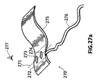
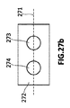
図27aは、第1の電気刺激電極273および第2の電気刺激電極274を備える、先行技術の圧力カフ270を模式的に示す。圧力カフは、膨張可能バッグ275、およびカフとモニタまたはカフを動作させるよう構成される同様のデバイスとの間に空気および電流を伝えるための可撓管276をさらに備えるものとして示される。
FIG. 27 a schematically shows a prior art pressure cuff 270 comprising a first
図27aはまた、電極273、274により電気刺激される神経の経路を表す理論線271を示す。圧力カフ270は、使用中に、電極273、274が、(線271によって理論的に表される)神経の少なくとも一部であるか、または神経「上の」手足の領域に配置されるよう構成される。
FIG. 27a also shows a
図27bは、図27aで示される領域272の、図27aに示した視点277からの拡大図を提供する。
FIG. 27b provides an enlarged view of the
図27cに示すように、圧力カフ270は、以下の要件に従って適切に配置される第1および第2の電極273、274および膨張可能バッグ275を、患者の手足(腕また脚のいずれか)に優先的に配置するよう構成される。
As shown in FIG. 27c, the pressure cuff 270 places the first and
第1の電極273は、アノード(または、正のリード)として機能し、尺骨神経278の近接位置に配置され、第2の電極274は、カソード(または、負のリード)として機能し、尺骨神経278の遠位位置に配置される。特定の要件は、さらに、上腕動脈279に、または上腕動脈279上に配置された膨張可能バッグ275を備える。
The
プリューガーの法則は、運動神経278の経路に配置された能動電極274と受動電極273とにより、能動電極274によって神経278に伝えられる電流により引き起こされる誘発筋反応が信頼性の高いものであることを確実にする条件を定義する。
Prueger's law states that the
表1に示すように、この法則は、能動電極274が遠位位置にあり、受動電極273が近接位置にある場合にのみ、誘発筋反応が、能動電極274によって伝えられる電流の強度の大きさにかかわらず、確実に発生すると結論づける。
As shown in Table 1, this rule is that the evoked muscle response is a measure of the magnitude of the current carried by the
本明細書において、遠位位置は、患者の胴体に対する対応する患者の手足の遠位位置を意味し、近接位置は、患者の胴体に対する対応する患者の手足の近接位置を意味する。 As used herein, a distal position refers to the distal position of the corresponding patient's limb relative to the patient's torso, and a proximal position refers to the proximal position of the corresponding patient's limb relative to the patient's torso.
プリューガーの法則によれば、運動神経278に配置された2つの電極273、274によって行われる電気刺激は、2つのパラメータに応じて、誘発筋反応(表1で「れん縮」と示される)を引き起こすことができる。第1のパラメータは、運動神経278を電気刺激するよう生成された電流の強度に関し、第2のパラメータは、神経278の経路における電極273、274の相対位置に関する。この第2のパラメータは、技術的に、「極性」と呼ばれる。
According to Prueger's law, the electrical stimulation performed by the two
表1は、この現象についての詳細なデータを提供する。ONという語は、電気刺激が神経に実際に印加された瞬間(閉回路状態)に関し、OFFという語は、電気刺激を停止した瞬間(開回路状態)に関する。 Table 1 provides detailed data on this phenomenon. The term ON relates to the moment when electrical stimulation is actually applied to the nerve (closed circuit state), and the term OFF relates to the moment when electrical stimulation is stopped (open circuit state).
表1において、電気刺激のために印加された電流に対する3つの異なる強度が、弱、中、および強として考慮される。表1の内容は、図27cに示すような、刺激する電流の強度が弱、中、または強であるかどうかにかかわらず、能動電極274が受動電極273に対して遠位位置に配置された場合にのみ、信頼できる筋反応を取得することができる導出を可能にする。
In Table 1, three different intensities for the current applied for electrical stimulation are considered as weak, medium and strong. Table 1 shows that the
しかしながら、同じ圧力カフを患者の左腕に変えた場合、実施者は、圧力カフを180°回転させ、図27dに示すように、刺激電極273、274および膨張可能バッグ275の両方の位置を、それぞれ、患者の左腕の末梢運動神経278および上腕動脈279と合わせることを強いられる。それにもかかわらず、そうすることによって、その場合、圧力カフ270の受動および能動電極273、274は、(表1に示すように)「近接位置でアクティブ」構成にしたがって、運動神経278に不可避的に配置される。
However, if the same pressure cuff is changed to the patient's left arm, the practitioner rotates the pressure cuff 180 ° and positions both the
表1に示すように、そのような「近接位置でアクティブ」構成は、運動神経で強度が強の刺激電流を印加した(ON)後、効果的な誘発筋反応(れん縮)を保証することができない重要な限界の影響を受ける。 As shown in Table 1, such an “active in close proximity” configuration ensures an effective evoked muscle response (spasticity) after applying a strong stimulation current (ON) in the motor nerve. Can't be affected by important limitations.
この電気生理学的現象は、技術的には、「伝導の陽極ブロック」として知られており、筋肉を刺激する運動神経が、電極の特定の配置を使用して、高い電流強度で刺激された場合の、患者の筋肉での特徴的な誘発筋反応の欠如を意味する。 This electrophysiological phenomenon is technically known as a “conducting anodic block” and when a motor nerve that stimulates muscles is stimulated with high current intensity using a specific arrangement of electrodes Meaning a lack of characteristic evoked muscle responses in the patient's muscles.
この特定の配置は、刺激回路の受動電極(アノード、正のリード)が能動電極(カソード、負のリード)よりも運動神経の経路上でより遠位に配置されることを備える。そのような状況は、表1で「非れん縮」で、「近位位置でアクティブ」極性が”ON”の列で、「強」電流の行である。 This particular arrangement comprises that the passive electrode (anode, positive lead) of the stimulation circuit is placed more distally on the motor nerve path than the active electrode (cathode, negative lead). Such a situation is a row of “strong” current in the column of “non-constricted”, “active in proximal position” polarity “ON” in Table 1.
前記「伝導の陽極ブロック」は、刺激回路が閉じている場合(表1におけるON)、刺激回路の受動電極の下で正に帯電した電界が現れた場合の起点を有する。そのような正に帯電した電界が存在することは、神経幹外膜のいわゆる過分極に繋がる。そのような過分極の大きさは、正に帯電した電界の強度に正比例し、同様に、神経を刺激するために印加された電流の強度に正比例する。 The “conductive anode block” has a starting point when a positively charged electric field appears under the passive electrode of the stimulation circuit when the stimulation circuit is closed (ON in Table 1). The presence of such a positively charged electric field leads to so-called hyperpolarization of the nerve trunk outer membrane. The magnitude of such hyperpolarization is directly proportional to the intensity of the positively charged electric field, and is also directly proportional to the intensity of the current applied to stimulate the nerve.
神経幹に沿った神経インパルスの伝達は、神経に沿った負に帯電した電波の伝達であると仮定することができる。したがって、能動電極と神経支配筋との間の神経幹における任意の位置の正に帯電した電界は、記載した負に帯電した電波の伝搬に対する電気バリアの役目を果たすことができる。したがって、正に帯電した電界は、受動電極、すなわち、アノード下で、関心筋肉に電気的神経インパルスを最終的に到達させることを遮断する可能性がある(このことは、「陽極ブロック」という用語で説明する)。 It can be assumed that the transmission of nerve impulses along the nerve trunk is the transmission of negatively charged radio waves along the nerve. Thus, a positively charged electric field at any position in the nerve trunk between the active electrode and innervating muscle can serve as an electrical barrier to the propagation of the negatively charged radio wave described. Thus, a positively charged electric field can block the electrical nerve impulse from finally reaching the muscle of interest under the passive electrode, ie the anode (this is the term “anode block”). Explained in).
「伝導の陽極ブロック」現象が気付かれずに発現すると、主として、強の電流刺激強度の「近接位置でアクティブ」電極の設定に従って、患者の末梢運動神経を刺激する場合に、神経筋遮断の評価中の医療ミスの潜在的な原因となる可能性がある。何らの筋反応も得られない場合、麻酔医は、患者が深い遮断状態にあると誤った診断をする可能性があり、一方、患者は、実際には、非遮断状態にある可能性がある。 When the “conducting anodic blocking” phenomenon occurs unknowingly, it is being evaluated for neuromuscular blockade, primarily when stimulating the patient's peripheral motor nerves according to the setting of the “active in proximity” electrode with a strong current stimulus intensity. Can be a potential cause of medical errors. If no muscle response is available, the anesthesiologist may make a false diagnosis that the patient is deeply blocked, while the patient may actually be unblocked .
運動性反応のそのような観測された欠如は、上流を刺激された運動神経の経路のさらなる遠位に配置される可能性のある受動電極下で、強く過分極化された神経区分での神経信号の伝達の望まない遮断によって実際に引き起こされる可能性がある。 Such observed lack of motility response is due to nerves in strongly hyperpolarized nerve segments under passive electrodes that may be placed further distal to the upstream stimulated motor pathway. It can actually be caused by an undesired blockage of signal transmission.
現在では、「伝導の陽極ブロック」現象の発生を防ぐ唯一の方法は、対応するソフトウェアを介して、圧力カフが左手足に配置される場合に、電極の極性を能動的に反転することである。しかしながら、そのような反転動作は、例えば、コンソール、モニタ、または同様のもので、実施者によって手動で実行される必要があり、この解決策は、失敗を生じさせない(failure proof)ものではない。 Currently, the only way to prevent the occurrence of the “conductive anode block” phenomenon is to actively reverse the polarity of the electrodes when the pressure cuff is placed on the left limb, via corresponding software. . However, such a reversal operation is, for example, a console, monitor, or the like and needs to be performed manually by the practitioner, and this solution is not a failure proof.
電気刺激回路を組み込む圧力カフは、米国特許第5957860号公報から知られる。そのような電気刺激回路は、例えば、電極のための金属板および電極を対応する電源に接続するための金属線などの従来の電気部品で作られる電極および関連接続部を備えることができる。 A pressure cuff incorporating an electrical stimulation circuit is known from US Pat. No. 5,957,860. Such an electrical stimulation circuit can comprise electrodes and associated connections made of conventional electrical components such as, for example, metal plates for electrodes and metal wires for connecting the electrodes to corresponding power sources.
圧力カフに組み込まれたこの種類の電気刺激回路は、比較的堅く、大きく、非人間工学的である可能性があり、その結果、このような電気刺激回路は、電流を電気刺激のために印加された患者を煩わせる可能性がある。さらに、前記回路の製造は、相対的に大量の手動動作が必要となる可能性があるので、複雑で、時間のかかる可能性がある。 This type of electrical stimulation circuit built into a pressure cuff can be relatively stiff, large and non-ergonomic, so that such an electrical stimulation circuit applies current for electrical stimulation. May be annoying to the patient. Furthermore, the manufacture of the circuit can be complicated and time consuming since a relatively large amount of manual operation may be required.
これらの電気刺激回路の圧力カフへの取り付け部には、回路により電気刺激を印加される患者の皮膚に、例えば、炎症などの、変化を引き起こす可能性のある接着剤か、または同様の物質を備える可能性がある。 The attachment of these electrical stimulation circuits to the pressure cuff is made of an adhesive or similar substance that can cause changes, such as inflammation, on the patient's skin to which electrical stimulation is applied by the circuit. There is a possibility to prepare.
本開示は、神経筋遮断状態を監視する先行技術の方法およびそのような方法に適切なシステムを向上することを目的とする。 The present disclosure aims to improve prior art methods for monitoring neuromuscular blockade and systems suitable for such methods.
第1の態様において、筋弛緩剤を投与された患者の神経筋遮断状態を自動的に判断するための方法を提供する。本方法は、複数の事前定義された神経筋遮断状態に基づき、事前定義された神経筋遮断状態のそれぞれは、あるサイクル周期で事前定義された1つまたは複数の刺激サイクルと、神経筋遮断状態から別の神経筋遮断状態に変更するための1つまたは複数の基準とを有する。1つまたは複数の基準は、神経筋遮断状態を、第1の他の神経筋遮断状態に変更するための第1の基準または基準の第1のセットを備える。 In a first aspect, a method is provided for automatically determining neuromuscular blockade in a patient receiving a muscle relaxant. The method is based on a plurality of predefined neuromuscular blocking states, each of the predefined neuromuscular blocking states including one or more predefined stimulation cycles and a neuromuscular blocking state. One or more criteria for changing from one to another neuromuscular block. The one or more criteria comprises a first criteria or a first set of criteria for changing a neuromuscular block state to a first other neuromuscular block state.
本方法は、神経筋遮断状態に対して事前に定義された1つまたは複数の刺激サイクルを自動的に実行すること、および実行された刺激サイクルの少なくとも一部に対する1つまたは複数の筋反応を自動的に判定することを備える。本方法は、筋反応と神経筋遮断状態を変更するための事前定義された基準とを自動的に比較することと、筋反応が事前定義された第1の基準または基準の第1のセットを満たす場合、第1の他の神経筋遮断状態のために事前定義された1つまたは複数の刺激サイクルを自動的に実行することとをさらに備える。 The method automatically performs one or more predefined stimulation cycles for a neuromuscular block state and performs one or more muscle responses to at least a portion of the performed stimulation cycle. Comprising automatically determining. The method automatically compares a muscle response and a predefined criterion for changing the neuromuscular block state, and determines a first criterion or a first set of criteria for which the muscle response is predefined. If so, further comprising automatically performing one or more stimulation cycles predefined for the first other neuromuscular block state.
本方法は、例えば、適切なシステムによって実行可能とすることができるコンピュータプログラムの形式で実施することができる。したがって、先行技術の方法における上述の欠点は、そのような手法で克服することができる。筋反応の導出と、結果として起こる後続の刺激信号の(再)構成は、麻酔専門医が(または、同様の人物)が連続的に、または周期的に注意を払うことを必要とすることなく、本方法/システムによって自動的に実行することができる。 The method can be implemented, for example, in the form of a computer program that can be executed by a suitable system. Thus, the above-mentioned drawbacks in prior art methods can be overcome in such a manner. The derivation of the muscle response and the subsequent (re) construction of the subsequent stimulation signal does not require the anesthesiologist (or similar person) to pay attention continuously or periodically, It can be performed automatically by the method / system.
本方法は、さまざまな事前定義された神経筋状態の間の遷移を、標的の事前定義された神経筋状態が実現されるまで、自動的に行うことができるような方法で、連続的に繰り返すことができる。患者に対する現在状態が与えられると、前記現在状態に対して事前定義された刺激サイクルを、前記刺激サイクルに対して事前定義された周期下で繰り返すことができる。実行される刺激サイクルのそれぞれは、前記刺激に対する筋反応を生み出す可能性がある。 The method continuously repeats in such a way that transitions between various predefined neuromuscular states can be made automatically until the target predefined neuromuscular state is achieved. be able to. Given a current state for a patient, a stimulation cycle predefined for the current state can be repeated under a period predefined for the stimulation cycle. Each stimulation cycle performed can produce a muscle response to the stimulation.
最後の筋反応の1つまたは複数は、現在状態に対して事前定義された1つの基準または基準のセットと比較することができる。基準または基準のセットの1つが満たされた場合、神経筋遮断状態は、現在状態から、満たされた基準に対して事前定義された新しい状態に変更することができる。したがって、現在状態は、以前の状態となり、一方、新しい状態が、現在状態となる。その場合、本方法の新しい繰り返しを、「新しい」現在状態に対して実行することができる。標的神経筋状態(例えば、非遮断状態)が達成されるまで続けられる。 One or more of the last muscle responses can be compared to a single criterion or set of criteria predefined for the current state. If one of the criteria or set of criteria is met, the neuromuscular block state can be changed from the current state to a new state predefined for the met criteria. Thus, the current state becomes the previous state, while the new state becomes the current state. In that case, a new iteration of the method can be performed on the “new” current state. Continue until a target neuromuscular state (eg, non-blocking state) is achieved.
しかしながら、本方法は、判定された筋反応の描写を表示することをさらに備えることができ、希望であれば、麻酔専門医が、考慮することができる。本方法はまた、「自動的な」事前定義された刺激サイクル、周期、および基準などの少なくともいくつかを(場合によると、一時的に)置き換えるための、麻酔専門医からの手動命令を受信するよう適合させることができる。 However, the method can further comprise displaying a depiction of the determined muscle response, which can be considered by an anesthesiologist if desired. The method also receives a manual command from an anesthesiologist to replace (possibly temporarily) at least some of the “automatic” predefined stimulation cycles, periods, and criteria, etc. Can be adapted.
いくつかの実装態様において、神経筋遮断状態から別の神経筋遮断状態に変更するための1つまたは複数の基準は、神経筋遮断状態の1つまたは複数に対する第2の基準または基準の第2のセットをさらに備えることができる。第2の基準または基準の第2のセットは、神経筋遮断状態を、第2の他の神経筋遮断状態に変更するために事前定義することができる。その場合、筋反応が前記事前定義された第2の基準または基準の第2のセットを満たす場合、第2の他の神経筋遮断状態に対して事前定義された1つまたは複数の刺激サイクルを、自動的に実行することができる。 In some implementations, the one or more criteria for changing from a neuromuscular blocking state to another neuromuscular blocking state is a second criterion or a second of the criteria for one or more of the neuromuscular blocking states. The set of can be further provided. A second criterion or a second set of criteria can be predefined to change a neuromuscular block state to a second other neuromuscular block state. In that case, one or more stimulation cycles predefined for a second other neuromuscular block state if a muscle response satisfies the predefined second criteria or a second set of criteria. Can be executed automatically.
事前定義された神経筋状態のそれぞれは、1つまたは複数の刺激サイクルと関連付けておくことができ、そのそれぞれが、例えば、単収れん(ST:Single Twitch)パターン、または4連反応(TOF:Train of Four)パターン、または反復刺激後カウント(PTC:Post−tetanic count)パターンなどの、刺激パターンに従って事前定義される。これらのパターンについてのより詳細な説明は、本記述の他の部分で提供することができる。 Each of the predefined neuromuscular states can be associated with one or more stimulation cycles, each of which is, for example, a single convergence (ST) pattern or a quadruple response (TOF) train. of Four, or a predefined pattern according to a stimulus pattern, such as a Post-Tetanic count (PTC) pattern. A more detailed description of these patterns can be provided elsewhere in this description.
各事前定義された神経筋遮断状態は、事前定義された1つまたは複数の刺激サイクルを有することができ、それぞれが、別の神経筋遮断状態に変更するための対応する基準または基準のセットを事前定義している。一例において、導入状態(遮断が患者に引き起こされていることを意味する)は、単一TOF刺激サイクル、および前記TOF刺激に対する1つまたは複数の応答に応じて単一の(第1の)基準もしくは基準の(第1の)セットを事前定義しておくことができる。 Each predefined neuromuscular block state can have one or more predefined stimulation cycles, each with a corresponding criterion or set of criteria for changing to another neuromuscular block state. Predefined. In one example, the inductive state (meaning that blockage is being caused to the patient) is a single (first) criterion in response to a single TOF stimulation cycle and one or more responses to said TOF stimulation. Alternatively, a (first) set of criteria can be predefined.
別の例において、深状態(患者が深く遮断されたと考えられることを意味する)は、TOFパターンに従って第1の刺激サイクルを事前定義し、TOFパターンよりも敏感なPTCパターンに従って第2の刺激サイクルを事前定義することができる。言い換えると、PTCパターンは、TOFパターンが検出できない神経筋伝達を検出することを可能にすることができる。 In another example, a deep condition (meaning that the patient is considered deeply blocked) predefines a first stimulation cycle according to the TOF pattern and a second stimulation cycle according to a PTC pattern that is more sensitive than the TOF pattern. Can be predefined. In other words, the PTC pattern can make it possible to detect neuromuscular transmission that the TOF pattern cannot be detected.
上記を考慮して、第1の基準または基準の第1のセットは、あまり深くない状態(例えば、中状態)に変更するためにTOF刺激サイクルに対して事前定義することができ、第2の基準または基準の第2のセットは、さらなる深状態(例えば、強状態)に変更するためにPTC刺激サイクルに対して事前定義することができる。1つまたは複数のTOF刺激サイクルを実行した後、何らの神経筋伝達も検出(または推測)されない場合、PTC刺激サイクルおよび第2の基準もしくは基準の第2のセットを適用して、より弱い神経筋伝達を推測することができ、それに応じて、前記第2の基準または基準の第2のセットで事前定義されたような新しい状態に変更することができる。 In view of the above, a first criterion or a first set of criteria can be predefined for a TOF stimulation cycle to change to a less deep state (eg, a middle state) A second set of criteria or criteria can be predefined for the PTC stimulation cycle to change to a further deep state (eg, strong state). If no neuromuscular transmission is detected (or inferred) after performing one or more TOF stimulation cycles, apply the PTC stimulation cycle and the second criterion or second set of criteria to apply weaker nerves Muscle transmission can be inferred and correspondingly changed to a new state as predefined in the second criteria or a second set of criteria.
例によれば、1つまたは複数の筋反応は、患者の手足に適用された圧力カフを通じて判断することができ、任意の筋反応は、圧力が、対応する実行された刺激サイクルへの前記手足の筋反応の結果としてカフで時間とともにどのように変化するかを表す圧力波の形式を有する。 According to an example, one or more muscle responses can be determined through a pressure cuff applied to the patient's limb, and any muscle response can be determined by the pressure and the limb to the corresponding performed stimulation cycle. It has a form of pressure wave that represents how the cuff changes with time as a result of muscle reaction.
代替例において、1つまたは複数の筋反応は、他の種類のセンサを通じて判断することができる。例えば、加速度計(例えば、患者の指先に配置される)は、加速測定方法の状況で使用することができ、および/または力センサを、筋音図方法の状況で使用することができる。 In the alternative, one or more muscle responses can be determined through other types of sensors. For example, an accelerometer (eg, placed on a patient's fingertip) can be used in the context of an acceleration measurement method and / or a force sensor can be used in the context of a myogram method.
第2の態様において、カフにおける圧力波を解析し、患者の心拍により生成された圧力パルスから干渉をフィルタリングすることによって、患者の筋肉の電気刺激に対する筋反応を判断する方法を提供する。特に、本方法は、患者の心拍の終点を判断すること、ならびに第1の電気刺激パルスおよび、それに続いて、1つまたは複数のさらなる電気刺激パルスの生成を引き起こすことによって筋肉の電気刺激を実行することを備える。第1の電気刺激パルスは、心拍の終点で実質的に生成される。 In a second aspect, a method is provided for determining a muscle response to an electrical stimulation of a patient's muscle by analyzing the pressure wave in the cuff and filtering the interference from pressure pulses generated by the patient's heartbeat. In particular, the method performs electrical stimulation of the muscle by determining the end point of the patient's heartbeat and causing the generation of a first electrical stimulation pulse followed by one or more additional electrical stimulation pulses. Prepare to do. The first electrical stimulation pulse is substantially generated at the end of the heartbeat.
本方法は、圧力が、電気刺激に対する筋反応として圧力カフで時間とともにどのように変化するかを表す圧力波の形式で筋反応を判断することをさらに備える。圧力波は、第1の電気刺激パルスおよびさらなる電気刺激パルスのそれぞれによって引き起こされる第1の圧力パルスおよびさらなる圧力パルスを備える。本方法は、第1の圧力パルスの上向き勾配の形状を示す第1の特性を判断することを備える。 The method further comprises determining a muscle response in the form of a pressure wave that represents how pressure changes over time with a pressure cuff as a muscle response to an electrical stimulus. The pressure wave comprises a first pressure pulse and a further pressure pulse caused by a first electrical stimulation pulse and a further electrical stimulation pulse, respectively. The method comprises determining a first characteristic indicative of the shape of the upward slope of the first pressure pulse.
圧力パルスの上向き勾配の第1の特性は、例えば、圧力パルスの振幅を上向き勾配の最大微分値で除算した結果とすることができる。 The first characteristic of the upward slope of the pressure pulse can be, for example, the result of dividing the amplitude of the pressure pulse by the maximum differential value of the upward slope.
本方法は、さらなる圧力パルスの少なくともいくつかに対して、さらなる圧力パルスの第1の特性を判断することと、さらなる圧力パルスの第1の特性および第1の圧力パルスの第1の特性の間の逸脱を判断することと、その逸脱が逸脱閾値を超えるかどうかを検証することとをさらに備える。 The method determines, for at least some of the additional pressure pulses, the first characteristic of the additional pressure pulse and between the first characteristic of the additional pressure pulse and the first characteristic of the first pressure pulse. And determining whether the deviation exceeds a deviation threshold.
患者の心拍の終点は、心拍を表すカーブを推測するための任意の既存のシステム/方法を使用することで判断することができる。このカーブは、上向き勾配、ピーク、および下向き勾配を有することができる。心拍の終点は、心拍カーブの下向き勾配が実質的に終了した場合に判断することができる。 The end point of the patient's heart rate can be determined using any existing system / method for inferring a curve representing the heart rate. This curve can have an upward slope, a peak, and a downward slope. The end point of the heartbeat can be determined when the downward slope of the heartbeat curve is substantially finished.
多様な実験により、ゼロより大きい振幅を伴う(筋反応における)全ての圧力パルスが、患者の心拍による干渉がない場合に、同様の形状を有する上向き勾配を有することが明らかになった。心拍の終点で第1の電気刺激パルスを生成することにより、第1の圧力パルス(前記第1の電気刺激パルスによって引き起こされた)が患者の心拍による干渉を受けないと仮定することを可能にすることができる。 Various experiments have shown that all pressure pulses (in muscle response) with amplitudes greater than zero have an upward slope with a similar shape in the absence of interference from the patient's heartbeat. By generating a first electrical stimulation pulse at the end of the heartbeat, it is possible to assume that the first pressure pulse (caused by the first electrical stimulation pulse) is not subject to interference by the patient's heartbeat can do.
したがって、さらなる圧力パルスの第1の特性と第1の圧力パルス(心拍の干渉を受けない)の第1の特性との間の偏差は、さらなる圧力パルスが患者の心拍によって歪められたことを示す可能性がある。その逸脱が逸脱閾値を下回る場合、その逸脱が実質的に小さいことを示し、第1の圧力パルスの第1の特性に基づく補正が、さらなる圧力パルスに印加されて、前記逸脱を少なくとも部分的に無くす(または、減じる)ことができる。 Thus, the deviation between the first characteristic of the further pressure pulse and the first characteristic of the first pressure pulse (not subject to heartbeat interference) indicates that the further pressure pulse has been distorted by the patient's heartbeat. there is a possibility. If the departure is below the departure threshold, it indicates that the departure is substantially small and a correction based on the first characteristic of the first pressure pulse is applied to the further pressure pulse to at least partially Can be eliminated (or reduced).
逸脱が逸脱閾値を超過するかどうかの検証について負の結果である場合、さらなる圧力パルスの調整が実行される。この調整は、さらなる圧力パルスのピーク(または、立ち上がり時間)までの時間が正確に測定され、上向き勾配の形状が第1の圧力パルスの第1の特性によって説明することができると仮定することによって実行される。 If the deviation is a negative result of verifying whether the deviation exceeds the deviation threshold, further pressure pulse adjustments are performed. This adjustment is by assuming that the time to the peak (or rise time) of the further pressure pulse is accurately measured and the shape of the upward slope can be explained by the first characteristic of the first pressure pulse. Executed.
いくつかの実装態様において、逸脱が逸脱閾値を超過するかどうかの検証について正の結果である場合、さらなる圧力パルスの調整は、第1の仮定または第2の仮定のいずれかに基づいて実行することができる。第1の仮定により、さらなる圧力パルスのピーク(または、立ち上がり時間)までの時間が正確に測定され、上向き勾配の形状が第1の圧力パルスの第1の特性によって説明することができると推定することができる。 In some implementations, if the deviation is a positive result for verification whether the deviation threshold is exceeded, further pressure pulse adjustment is performed based on either the first assumption or the second assumption. be able to. The first assumption presumes that the time to the peak (or rise time) of the further pressure pulse is accurately measured and the shape of the upward slope can be explained by the first characteristic of the first pressure pulse. be able to.
第2の仮定により、さらなる圧力パルスのピーク(または、立ち上がり時間)までの時間が正確に測定され、上向き勾配の形状が、測定されたさらなる圧力パルスから基準の心拍パルスを実質的に減算することによって説明することができると推定することができる。 According to the second assumption, the time to peak (or rise time) of the further pressure pulse is accurately measured and the shape of the upward slope substantially subtracts the reference heart rate pulse from the measured further pressure pulse. It can be estimated that it can be explained by
さらなる圧力パルスの第1の特性と第1の圧力パルスの第1の特性との間の逸脱が逸脱閾値を超える場合、歪みは実質的に大きいことを示す可能性があり、第1の補正または第2の補正のいずれかをさらなる圧力パルスに適用して、前記歪みを少なくとも部分的に無くする(または、減じる)ことができる。 If the deviation between the first characteristic of the further pressure pulse and the first characteristic of the first pressure pulse exceeds the deviation threshold, the distortion may indicate that it is substantially large, and the first correction or Any of the second corrections can be applied to further pressure pulses to at least partially eliminate (or reduce) the distortion.
第1の補正は、第1の圧力パルスの第1の特性に基づくことができ、第2の補正は、測定されたさらなる圧力パルスから基準の心拍パルスを実質的に減算することに基づくことができる。第1または第2の補正は、補正の重要性に応じて選択することができる。例えば、重要性が小さな補正は、過剰な補正をさらなる圧力パルスに印加することを避けるために選択することができる。 The first correction may be based on a first characteristic of the first pressure pulse, and the second correction may be based on substantially subtracting a reference heart rate pulse from the measured additional pressure pulse. it can. The first or second correction can be selected according to the importance of the correction. For example, less important corrections can be selected to avoid applying excessive corrections to further pressure pulses.
したがって、本方法は、患者の心拍による小さな歪みがあってもなくても、「フィルタされた」筋反応を判断することを可能にすることができる。これらの方法は、本明細書の他の部分で説明するもののように電気刺激カフを使用することに基づく方法で使用することができる。これらの方法は、前記方法を使用する場合、より信頼できる結果を生成することができる。 Thus, the method can allow a “filtered” muscle response to be determined with or without minor distortion due to the patient's heart rate. These methods can be used in a method based on using an electrical stimulation cuff, such as those described elsewhere herein. These methods can produce more reliable results when using the method.
またさらなる態様において、患者の皮膚、好ましくは、無傷の皮膚に乾燥して(すなわち、乾燥用途に適切に)適用されるよう構成される、電気刺激電極が提供される。乾燥用途の概念は、任意の導電性ゲルを下に適用する必要無く、電気刺激電極を適用することに関することができる。 In yet a further aspect, an electrostimulation electrode is provided that is configured to be applied dry (ie, suitably for dry applications) to a patient's skin, preferably intact skin. The concept of drying application can relate to applying an electrostimulation electrode without the need to apply any conductive gel below.
電気刺激電極は、サポート層、導電媒体、および第1の導電層を備える。サポート層は、電気絶縁体から作られ、1つまたは複数の穴を伴う少なくとも1つの領域を有する。サポート層は、使用中、サポート層の第1の面(すなわち、外面)が患者の皮膚と接触するように配置される。したがって、サポート層のこの外面は、患者の皮膚と接触することを目的とする。 The electrical stimulation electrode includes a support layer, a conductive medium, and a first conductive layer. The support layer is made from an electrical insulator and has at least one region with one or more holes. The support layer is positioned such that, in use, the first surface (ie, the outer surface) of the support layer is in contact with the patient's skin. Thus, this outer surface of the support layer is intended to contact the patient's skin.
導電媒体が、第1の面と反対側のサポート層の第2の面(すなわち、内面)に貼り付けられ、穴を伴う領域を、導電媒体が前記穴を伴う領域を覆わないように、完全に、または部分的に取り囲むよう配置される。言い換えると、導電媒体は、穴を伴う領域の周りに配置され、導電媒体は、導電媒体が前記領域(穴を伴う)と重ならないように、前記領域(穴を伴う)を完全に、または部分的に取り囲む。 The conductive medium is affixed to the second surface (i.e., the inner surface) of the support layer opposite the first surface to completely cover the area with holes so that the conductive medium does not cover the areas with holes. Or partially surrounding. In other words, the conductive medium is arranged around a region with holes, and the conductive medium completely or partially covers the region (with holes) so that the conductive medium does not overlap with the region (with holes). Enclose.
第1の導電層は、第1の導電層が穴を伴う領域を覆う(または、穴を伴う領域と重なる)ように、導電媒体と接触する。 The first conductive layer is in contact with the conductive medium such that the first conductive layer covers the region with holes (or overlaps the region with holes).
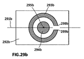
本電気刺激電極が、患者の皮膚に火傷を引き起こす危険性を実質的に無くする。この効果は、導電媒体が穴を伴う前記領域を(完全に、または部分的に)取り囲むため、電流が、(サポート層の)1つまたは複数の穴を通じて、周囲位置から患者の皮膚に伝えられるために達成される。したがって、導電媒体によって伝えられた電流は、導電媒体自体から直接患者の皮膚に到達することはできない。 The electrical stimulation electrode substantially eliminates the risk of causing burns to the patient's skin. This effect is because the conductive medium surrounds the region with holes (completely or partially), so that current is transmitted from the surrounding location to the patient's skin through one or more holes (of the support layer). To be achieved. Thus, the current carried by the conductive medium cannot reach the patient's skin directly from the conductive medium itself.
さらに別の態様において、ハイブリッド空気信号コネクタが、空気信号管を電気刺激カフに接続するために設けられる。したがって、ハイブリッド空気信号コネクタは、電気刺激カフを、圧縮空気および電気パルスを導入する管と接続することを目的とする。電気刺激カフは、内側導電トラックと、接続ボアとを有することができ、空気信号管は、空気路と導電ケーブルとを有することができる。 In yet another aspect, a hybrid air signal connector is provided for connecting the air signal tube to the electrical stimulation cuff. The hybrid air signal connector is therefore aimed at connecting the electrical stimulation cuff with a tube introducing compressed air and electrical pulses. The electrical stimulation cuff can have an inner conductive track and a connection bore, and the air signal tube can have an air path and a conductive cable.
ハイブリッド空気信号コネクタは、主本体と、2つの接続電極とを備える。主本体は、空気が第1の管状部分を通って空気路とカフの内部との間を流れることができるよう、使用中に、第1の管状部分が空気信号管の空気路に適合されるようにベースの第1の面に配置される第1の管状部分を伴うベースを有する。言い換えると、主本体は、その中心から、管状部分が一方の側、いわゆる、外側に伸びるベースを備え、管状部分は、管を結合するためにある。 The hybrid air signal connector includes a main body and two connection electrodes. The main body is adapted so that, during use, the first tubular portion is adapted to the air path of the air signal tube so that air can flow between the air passage and the interior of the cuff through the first tubular portion. Having a base with a first tubular portion disposed on the first surface of the base. In other words, the main body comprises a base from which the tubular part extends to one side, the so-called outward, which is for joining the tubes.
2つの接続電極は、L型または実質的に平型のいずれかとすることができる。 The two connection electrodes can be either L-shaped or substantially flat.
接続電極は、(外部ケーブルと接続するための)外部端子と、(カフの内部での導電トラックと接続するための)内部端子とを有する。 The connection electrode has an external terminal (for connecting with an external cable) and an internal terminal (for connecting with a conductive track inside the cuff).
L型電極の場合、外部端子は、使用時に各外部端子が空気信号管の導電ケーブルの1つと接続するように、ベースから、第1の管状部分に並列に(および、任意選択的に、隣接して)延在する。 In the case of an L-shaped electrode, the external terminals are connected in parallel (and optionally, adjacent) from the base to the first tubular portion such that each external terminal connects with one of the conductive cables of the air signal tube in use. Extend).
実質的に平型の電極の場合、外部端子は、使用時にこの端部が空気信号管の導電ケーブルと接触するように、端部がベースの第1の面に配置されるようにベースに埋め込まれる。 In the case of a substantially flat electrode, the external terminal is embedded in the base such that the end is placed on the first surface of the base so that the end contacts the conductive cable of the air signal tube in use. It is.
(L型または実質的に平型の電極の)内部端子は、ハイブリッド空気信号コネクタがカフの接続ボアに導入される場合に、使用時に端部がカフの内側導電トラックの1つと接触するように、端部がベースの第1の面に配置されるようベースに埋め込まれる。言い換えると、内部端子は、終端がベースの外側に露出するようベースに埋め込まれ、その結果、ハイブリッド空気信号コネクタが、カフの接続ボアに導入される場合、前記端部が、トラックと接触する。 The internal terminal (of the L-shaped or substantially flat electrode) is such that when the hybrid air signal connector is introduced into the connection bore of the cuff, the end contacts the one of the cuff's inner conductive tracks when in use. , Embedded in the base such that the end is located on the first surface of the base. In other words, the internal terminal is embedded in the base such that the end is exposed outside the base, so that when the hybrid air signal connector is introduced into the connection bore of the cuff, the end contacts the track.
本ハイブリッド空気信号コネクタは、空気信号管を電気刺激カフに比較的効率的に接続することを可能にする。空気信号管に備えられた電線をカフの内側導電トラックに比較的効率的に接続することは、その接続電極の特定の構成および配置の結果として、前記ハイブリッド空気信号コネクタを通じて効率的に実現することができる。 The hybrid air signal connector allows the air signal tube to be connected to the electrical stimulation cuff relatively efficiently. The relatively efficient connection of the wires provided in the air signal tube to the inner conductive track of the cuff is efficiently realized through the hybrid air signal connector as a result of the specific configuration and arrangement of its connecting electrodes. Can do.
ハイブリッド空気信号コネクタはまた、コネクタの第1の管状領域が管の空気路に適合される場合、管とカフとの間の効率的な空気の流れを可能にすることができる。適切な空気圧気密性、液体および/または埃の侵入に対する保護、突然の引っ張りに対する機械的抵抗、および皮膚に優しい性質はまた、例えば、製造するために適切な材料が選ばれた場合、前記ハイブリッド空気信号コネクタによってもたらすことができる。 The hybrid air signal connector can also allow efficient air flow between the tube and the cuff when the first tubular region of the connector is adapted to the air path of the tube. Proper pneumatic tightness, protection against ingress of liquids and / or dust, mechanical resistance to sudden pulls, and skin-friendly properties can also be achieved, for example, when the appropriate material is selected to manufacture the hybrid air Can be provided by a signal connector.
またさらなる態様において、圧力カフは、患者の手足の周りに配置されるよう構成され、能動的電気刺激電極および受動的電気刺激電極を備えて提供される。 In yet a further aspect, the pressure cuff is configured to be placed around a patient's limb and provided with an active electrical stimulation electrode and a passive electrical stimulation electrode.
能動的電気刺激電極(カソードまたは負のリード)は、電流を伝えるよう構成され、使用中に能動的電気刺激電極の接触面が、神経が伝えられた電流の少なくとも一部を受け取るように少なくとも部分的に手足の末梢運動神経がある手足の第1の領域に配置されるように、圧力カフに配置される。 The active electrical stimulation electrode (cathode or negative lead) is configured to conduct current and at least a portion so that, during use, the contact surface of the active electrical stimulation electrode receives at least a portion of the conducted current In particular, it is placed on the pressure cuff so that it is placed in the first region of the limb with the peripheral motor nerves of the limb.
受動的電気刺激電極(アノードまたは正のリード)は、電流を収集するよう構成され、使用中に受動的電気刺激電極の接触面が手足の第2の領域に配置されるように圧力カフに配置され、伝えられた電流が受動的電気刺激電極によって収集される。 The passive electrical stimulation electrode (anode or positive lead) is configured to collect current and is placed in the pressure cuff so that the contact surface of the passive electrical stimulation electrode is placed in the second region of the limb during use. And the transmitted current is collected by a passive electrical stimulation electrode.
手足の第2の領域には、末梢運動神経がなく、および/または受動的電気刺激電極の接触面は、能動的電気刺激電極の接触面より実質的にサイズが大きい。 There is no peripheral motor nerve in the second region of the limb and / or the contact surface of the passive electrical stimulation electrode is substantially larger than the contact surface of the active electrical stimulation electrode.
本圧力カフは、末梢運動神経を電気刺激した結果としてカフから取得される誘発筋反応の強度を測定することによって、全身麻酔をかけられた患者の薬剤誘発性神経筋遮断状態を評価するために使用することができる。 This pressure cuff is used to evaluate drug-induced neuromuscular blockade in general anesthetized patients by measuring the intensity of the evoked muscle response obtained from the cuff as a result of electrical stimulation of peripheral motor nerves. Can be used.
誘発筋反応のこの強度は、適切なコンピューティングアルゴリズムを使用して、各筋運動反応についてカフの膨張可能バッグの内部で生じる空気圧ピークの大きさを測定することによって判断することができる。 This intensity of evoked muscle response can be determined by measuring the magnitude of the air pressure peak that occurs inside the cuff inflatable bag for each muscle motion response using an appropriate computing algorithm.
本明細書の他の部分に記載するように、「伝導の陽極ブロック」として知られる現象は、電気刺激によって引き起こされる神経インパルスの伝達をブロックする可能性があり、これは誘発筋反応の欠如を引き起こすことがある。「伝導の陽極ブロック」現象が気付かれずに発現することは、患者の神経筋遮断状態を評価する間、場合によっては、医療ミスの元となる可能性がある。 As described elsewhere in this specification, a phenomenon known as “conducting anodic block” may block the transmission of nerve impulses caused by electrical stimulation, which is a lack of evoked muscle response. May cause. The unintentional manifestation of the “conductive anodic block” phenomenon can be a source of medical error in some cases while assessing the patient's neuromuscular blockade.
本圧力カフの場合、場合によっては、「伝導の陽極ブロック」現象が気付かれずに発現したことにより患者の神経筋遮断を誤って評価する危険性を実質的に減らすか、無くす。 In the case of this pressure cuff, in some cases, the risk of erroneously assessing the patient's neuromuscular blockage due to the unknowingly manifestation of the “conductive anodic block” phenomenon is substantially reduced or eliminated.
本圧力カフが能動電極に対して近接位置に受動電極を伴い患者の右腕または左腕のいずれかに配置される場合、信頼できる誘発筋反応は、常に、プリューガーの法則に従って発生する。この原理は、受動電極が運動神経の経路に配置されているかいないかは関係なく、受動電極が能動電極よりサイズが大きいか大きくないかは関係ない。 When this pressure cuff is placed in either the patient's right arm or left arm with a passive electrode in close proximity to the active electrode, a reliable evoked muscle response always occurs according to Prueger's law. This principle does not depend on whether or not the passive electrode is placed in the motor nerve path, and does not depend on whether the passive electrode is larger or larger than the active electrode.
本圧力カフを用いる場合、患者の右腕または左腕のいずれに配置されるかにかかわらず、能動電極に対して遠位位置に受動電極があっても、信頼性のある誘発筋反応が発生する。 When this pressure cuff is used, a reliable evoked muscle response occurs regardless of whether it is placed on the patient's right arm or left arm, even if the passive electrode is distal to the active electrode.
受動電極が(遠位位置にある場合でも)運動神経の経路に配置されない場合、「伝導の陽極ブロック」現象が気付かれずに発現したため、前記神経幹に沿った神経インパルスの通常の伝達が遮断される危険性は、存在しないであろう。これは、(遠位位置での)受動電極が運動神経の影響領域の外側に配置され、その結果、神経の外膜の過分極が受動電極によってもはや引き起こされない可能性があるためである。神経インパルスの伝達が気付かれずに遮断される危険性をそのように回避することは、患者の皮膚にある(遠位位置の)受動電極の接触面のサイズに関係ない。 If the passive electrode is not placed in the motor nerve path (even if it is in the distal position), the “conducting anodic blocking” phenomenon manifests itself unintentionally, blocking normal transmission of nerve impulses along the nerve trunk. There will be no dangers. This is because the passive electrode (in the distal position) is placed outside the affected area of the motor nerve, so that hyperpolarization of the nerve outer membrane may no longer be caused by the passive electrode. So avoiding the risk of unintentionally blocking the transmission of nerve impulses is independent of the size of the contact surface of the passive electrode (distal position) on the patient's skin.
(遠位位置の)受動電極が運動神経の経路に配置され、患者の皮膚との接触面が能動電極の接触面より大きいサイズを有する場合、「伝導の陽極ブロック」現象が気付かれずに発現することにより神経幹に沿った神経インパルスの通常の伝達を遮断する危険性はまた、比較的小さくなるか、または存在しなくなる可能性がある。これは、より大きなサイズの受動電極が、患者の皮膚での受動電極の前記接触面の任意の点に存在する電流の密度を効率的に減らす拡散器の役目を果たすためである。結果的に、この低密度の電流はまた、前記接触面の下で比較的弱い正に帯電した電界を生成し、運動神経幹の外膜で比較的低い過分極レベルを引き起こす。したがって、「伝導の陽極ブロック」現象の発現する危険性は、著しく減少するか、無くなる。 When the passive electrode (distal position) is placed in the motor nerve path and the contact surface with the patient's skin has a larger size than the contact surface of the active electrode, the “conducting anodic blocking” phenomenon occurs unnoticeably The risk of blocking the normal transmission of nerve impulses along the nerve trunk may also be relatively small or absent. This is because the larger size passive electrode serves as a diffuser that effectively reduces the density of current present at any point on the contact surface of the passive electrode on the patient's skin. Consequently, this low density current also creates a relatively weak positively charged electric field under the contact surface, causing a relatively low hyperpolarization level in the outer membrane of the motor nerve trunk. Therefore, the risk of developing the “conductive anode block” phenomenon is significantly reduced or eliminated.
いくつかの例において、手足の第2の領域には、手足の末梢運動神経が少なくとも部分的にある可能性があり、および受動的電気刺激電極の接触面は、能動的電気刺激電極の接触面より実質的にサイズが大きい可能性がある。特定の例によっては、受動的電気刺激電極の接触面は、例えば、実質的に同軸状に能動的電気刺激電極の接触面を実質的に完全に取り囲むことができる。 In some examples, the second region of the limb may be at least partially with peripheral motor nerves of the limb and the contact surface of the passive electrical stimulation electrode may be the contact surface of the active electrical stimulation electrode. It may be substantially larger in size. In certain instances, the contact surface of the passive electrical stimulation electrode can substantially completely surround the contact surface of the active electrical stimulation electrode, for example, substantially coaxially.
能動電極がより大きな受動電極によって完全に取り囲まれた有利な態様は、患者の心臓の電気的保護が改善された可能性があることであるだろう。これは、受動電極のより大きな接触面が電気刺激電流に対する効率的で優先的な出口を構成し、その結果、前記電流が患者の心臓に向かって流れないことに基づく。この結論は、電気刺激電流に対するそのような優先的な出口が、能動電極の周りを360度完全にカバーすることにさらに基づくことができる。 An advantageous aspect in which the active electrode is completely surrounded by a larger passive electrode would be that the electrical protection of the patient's heart may have been improved. This is based on the fact that the larger contact surface of the passive electrode constitutes an efficient and preferential exit for the electrical stimulation current, so that the current does not flow towards the patient's heart. This conclusion can be further based on such preferential exit for electrical stimulation current covering 360 degrees completely around the active electrode.
受動電極が能動電極よりも大きいいくつかの例において、受動的電気刺激電極の接触面は、能動的電気刺激電極の接触面を部分的に囲んでもよい。例えば、受動的電気刺激電極は、実質的にC型とすることができる。他の例において、受動的電気刺激電極は、2つの環状部分として形成することができ、それぞれが第1の端部と第2の端部を有し、第1の端部は、その間に第1のギャップを伴って互いに向かい合い、第2の端部は、その間に第2のギャップを伴って互いに向かい合う。 In some instances where the passive electrode is larger than the active electrode, the contact surface of the passive electrical stimulation electrode may partially surround the contact surface of the active electrical stimulation electrode. For example, the passive electrical stimulation electrode can be substantially C-shaped. In other examples, the passive electrical stimulation electrode can be formed as two annular portions, each having a first end and a second end, the first end being between the first end and the second end. Facing each other with a gap of one, the second end faces each other with a second gap in between.
これらの最後の構成(C型および環状部分に基づくもの)の態様は、以前に説明した電流密度の拡散効果から恩恵を受けることとすることができる。したがって、「伝導の陽極ブロック」現象の発現する危険性は、著しく減少するか、無くなる。さらに、受動電極はまた、電気刺激電流に対する効率的で優先的な出口を構成することができ、能動電極の周りをほぼ完全に360度カバーし、患者の心臓の電気保護を改善することができる。 The aspects of these last configurations (based on the C-type and annular portions) can benefit from the previously described current density spreading effect. Therefore, the risk of developing the “conductive anode block” phenomenon is significantly reduced or eliminated. In addition, the passive electrode can also constitute an efficient and preferential exit for the electrical stimulation current, covering almost completely 360 degrees around the active electrode and improving the electrical protection of the patient's heart. .
圧力カフの文脈で説明した能動電極および受動電極の任意の以前の構成は、単一の多層膜として形成された電気刺激回路に対する記述の他の部分で説明した特徴および原理に基づいて、実現することができる。 Any previous configuration of active and passive electrodes described in the context of a pressure cuff is realized based on the features and principles described elsewhere in the description for the electrical stimulation circuit formed as a single multilayer film be able to.
さらに別の態様において、電気刺激回路は、電極部分およびトラック部分を備えて設けられる。電極部分は、患者の末梢運動神経を電気刺激するため、患者の皮膚のある領域に電流を送るか、または電流を収集するよう構成される。トラック部分は、電極部分に、または電極部分から、電流を伝えるよう構成される。電極部分およびトラック部分は、複数の層を有する単一の多層膜として一体化されて形成される。 In yet another aspect, the electrical stimulation circuit is provided with an electrode portion and a track portion. The electrode portion is configured to send current to or collect current in an area of the patient's skin for electrical stimulation of the patient's peripheral motor nerves. The track portion is configured to conduct current to or from the electrode portion. The electrode portion and the track portion are integrally formed as a single multilayer film having a plurality of layers.
複数の層は、互いに付着した第1の層と第2の層とを備える。第1の層は、例えば、熱可塑性ポリウレタン(TPU:Thermoplastic polyurethane)および/またはポリ塩化ビニル(PVC:Polyvinyl chloride)などの熱可塑性ポリマで生成することができ、例えば、黒鉛粒子などの導電性粒子でドーピングすることができる。第2の層は、例えば、炭素繊維および/または金属メッシュを備えることができる導電性繊維などの導電材料で生成することができる。 The plurality of layers includes a first layer and a second layer attached to each other. The first layer can be made of a thermoplastic polymer such as, for example, thermoplastic polyurethane (TPU) and / or polyvinyl chloride (PVC), for example, conductive particles such as graphite particles. Can be doped. The second layer can be made of a conductive material such as, for example, conductive fibers that can comprise carbon fibers and / or metal mesh.
本電気刺激回路は、容易にスケールアップすることができるように製造することができる。熱連続積層などの単一ステップ製造処理で製造してもよい。さらに、これらの電気刺激回路は、第1の層の熱可塑性ポリマの溶接特性により、接着剤または同様の物質を使う必要無く、圧力カフカバーに後に容易に接着することができる。 The electrical stimulation circuit can be manufactured so that it can be easily scaled up. You may manufacture by single-step manufacturing processes, such as thermal continuous lamination. In addition, these electrical stimulation circuits can be later easily bonded to the pressure cuff cover without the need to use adhesives or similar materials due to the welding properties of the first layer of thermoplastic polymer.
第1の層により、神経を刺激するために、電極部分と患者の皮膚の標的領域との間で、電気について肌に優しい伝達を可能にすることができる。第2の層は、回路の電極部分に、または電極部分から、電気を伝えるため、トラック部分に効率的な導電特性をもたらすことができる。 The first layer may allow skin-friendly transmission of electricity between the electrode portion and the target area of the patient's skin to stimulate the nerve. Since the second layer conducts electricity to or from the electrode portion of the circuit, it can provide efficient conductive properties to the track portion.
いくつかの例において、複数の層は、第2の層に貼り付けられる熱可塑性ポリマの第3の層をさらに備えることができ、第2の層は、第1の層と第3の層との間に挟まれる。この第3の層は、導電性粒子でドーピングされた熱可塑性ポリマで生成することができる。 In some examples, the plurality of layers can further comprise a third layer of thermoplastic polymer that is affixed to the second layer, wherein the second layer includes the first layer and the third layer. It is sandwiched between. This third layer can be made of a thermoplastic polymer doped with conductive particles.
例によれば、複数の層の層は、加熱積層処理で互いに貼り付けることができる。この処理は、単一ステップ処理とすることができ、したがって、例えば、(例えば、プリンテッドエレクトロニクスおよび/または気相蒸着技術で使用される)薄膜の層ごとの堆積などの他の製造処理と比べて複雑ではなく、時間の消費も少ない電気刺激回路の生成を可能にする。 According to an example, the plurality of layers can be attached to each other by a heat lamination process. This process can be a single step process and thus compared to other manufacturing processes such as, for example, layer-by-layer deposition of thin films (eg, used in printed electronics and / or vapor deposition techniques). It is possible to generate an electrical stimulation circuit that is not complicated and consumes less time.
さらに、上記の積層処理は連続的な製造処理であるため、規模の経済性から生じる費用削減の点からさらに利益をもたらす。より詳細な説明は、本明細書の他の部分で提供する。 Furthermore, since the lamination process described above is a continuous manufacturing process, it provides further benefits in terms of cost reduction resulting from economies of scale. A more detailed description is provided elsewhere herein.
例において、患者の手足の周りに配置されるよう構成することができ、以前の電気刺激回路の少なくとも1つを備えることができる、圧力カフを提供することができる。電気刺激回路は、使用中に、電気刺激回路の電極部分の接触面が手足の領域に配置されて、末梢運動神経を電気刺激するために手足の前記領域に、または前記領域から、電極部分によって電流を伝達または収集することができるように、圧力カフに貼り付けることができる。 In an example, a pressure cuff can be provided that can be configured to be placed around a patient's limb and can include at least one of the previous electrical stimulation circuits. The electrical stimulation circuit is in use by the electrode portion to or from the region of the limb to electrically stimulate peripheral motor nerves, with the contact surface of the electrode portion of the electrical stimulation circuit placed in the region of the limb during use It can be affixed to a pressure cuff so that current can be transmitted or collected.
電気刺激回路の圧力カフへの貼り付けは、熱可塑性ポリマで生成された電気刺激回路の層の、熱可塑性ポリマで生成された圧力カフの領域への貼り付けを備えることができる。例えば、圧力カフは、電気刺激回路の熱可塑性ポリマの層を貼り付けることができる、熱可塑性ポリマで生成された層を有する繊維カバーを備えることができる。この繊維カバーは、例えば、加熱積層処理により、熱可塑性ポリマの層に貼り付けられる、ナイロン、紙、または不織布で生成されたさらなる層を備えることができる。 The application of the electrical stimulation circuit to the pressure cuff may comprise the application of a layer of the electrical stimulation circuit made of the thermoplastic polymer to the region of the pressure cuff generated of the thermoplastic polymer. For example, the pressure cuff can comprise a fiber cover having a layer made of thermoplastic polymer to which a layer of thermoplastic polymer of an electrical stimulation circuit can be applied. The fiber cover can comprise an additional layer made of nylon, paper, or nonwoven fabric that is applied to the layer of thermoplastic polymer, for example, by a heat lamination process.
ナイロン、紙、または不織布のそのような層は、繊維カバーの外層とすることができ、熱可塑性ポリマの層は、繊維カバーの内層とすることができ、比較的小型で耐性のある圧力カフを得ることができる。ナイロン、紙、または不織布の外層は、一般に、カフに十分な強度をもたらすことができ、一方、熱可塑性ポリマの内層は、電気刺激回路のカフへの比較的強い貼り付けを可能にすることができる。これはまた、圧力カフの膨張可能バッグが漏出しないように機能することができる。 Such a layer of nylon, paper, or nonwoven can be the outer layer of the fiber cover, and the layer of thermoplastic polymer can be the inner layer of the fiber cover, creating a relatively small and resistant pressure cuff. Can be obtained. The outer layer of nylon, paper, or non-woven can generally provide sufficient strength to the cuff, while the inner layer of thermoplastic polymer can allow a relatively strong application to the cuff of the electrical stimulation circuit. it can. This can also function to prevent the pressure cuff inflatable bag from leaking out.
回路の熱可塑性ポリマ層と繊維カバーの熱可塑性ポリマ層との間の貼り付けは、溶接処理で実施することができる。この溶接処理は、例えば、熱板溶接処理、または超音波溶接処理、または高周波溶接処理とすることができる。高周波溶接処理を使用する有利な態様は、溶接される材料の外面の折れ、裂け、および/または歪みの発現を効率的に避けることができることとすることができる。この利点は、溶接される2つの層の間の特定の接触界面で高周波溶接処理のみが、室温で前記層の残りの部分を保持しながら、熱を印加するためである。 The application between the thermoplastic polymer layer of the circuit and the thermoplastic polymer layer of the fiber cover can be performed by a welding process. This welding process can be, for example, a hot plate welding process, an ultrasonic welding process, or a high frequency welding process. An advantageous aspect of using a high frequency welding process may be that the outer surface of the material to be welded can be efficiently avoided from breaking, tearing and / or developing strain. This advantage is due to the fact that only the high frequency welding process at the specific contact interface between the two layers to be welded applies heat while retaining the rest of the layer at room temperature.
単一の多層膜として形成された以前の電気刺激回路および関連する原理のいずれも、本明細書の他の部分で説明する能動的電気刺激電極および受動的電気刺激電極を伴う圧力カフのいずれかを製造するために使用することができる。 Any of the previous electrical stimulation circuits formed as a single multilayer film and the associated principles are any of the pressure cuffs with active and passive electrical stimulation electrodes described elsewhere herein. Can be used to manufacture.
本開示の非限定の例を、添付図面を参照して、以下で説明する。 Non-limiting examples of the present disclosure are described below with reference to the accompanying drawings.
図1から図8は、患者に対する神経筋遮断状態を自動的に判断する方法の状況における状態の間の自動的な遷移を模式的に示すフローチャートである。手術の間、環境に応じて、神経筋伝達は、患者に筋弛緩剤を投与することによって遮断することができ、前記遮断は、終了させるための薬剤を患者に投与することによって元に戻すことができる。 1 to 8 are flowcharts schematically illustrating automatic transitions between states in the context of a method for automatically determining a neuromuscular block state for a patient. During surgery, depending on the environment, neuromuscular transmission can be blocked by administering a muscle relaxant to the patient, which can be reversed by administering to the patient a drug to terminate. Can do.
本方法は、複数の神経筋遮断状態を事前定義しておくことに基づき、事前定義された神経筋遮断状態のそれぞれは、あるサイクル周期で事前定義された1つまたは複数の刺激サイクルと、神経筋遮断状態から別の神経筋遮断状態に変更するための1つまたは複数の基準とを有する。 The method is based on pre-defining a plurality of neuromuscular block states, wherein each of the predefined neuromuscular block states includes one or more stimulation cycles predefined in a cycle period, and a neuron block state. One or more criteria for changing from a muscle blocking state to another neuromuscular blocking state.
事前定義された神経筋状態の例は、例えば、導入状態、中状態、深状態、強状態、復帰状態、および復帰終了状態とすることができる。非遮断状態は、本方法を終了させることができる何らかの終了条件が生じたことを示す「仮想」状態としてもよい。 Examples of predefined neuromuscular states can be, for example, an introduction state, a middle state, a deep state, a strong state, a return state, and a return end state. The non-blocking state may be a “virtual” state indicating that some termination condition that can terminate the method has occurred.
導入状態は、筋弛緩剤が患者に投与されており、筋弛緩剤の影響が、所望の神経筋遮断に向けて進行中であることを意味することができる。 The introduced state can mean that a muscle relaxant is being administered to the patient and that the effect of the muscle relaxant is in progress towards the desired neuromuscular blockade.
中状態は、神経筋遮断があまり高くない状態で達成され、その結果、TOF(4連反応)刺激への何らかの反応、例えば、1から3の間のTOFカウントが生じる可能性があることを意味することができる。 Medium state means that neuromuscular blockade is achieved with not very high, resulting in some response to TOF (quadruple response) stimulation, eg, a TOF count between 1 and 3 can do.
深状態は、神経筋遮断がより高い状態で達成され、その結果、TOF刺激に対して何らの反応も取得できないが、PTC(反復刺激後カウント)刺激への何らかの反応が発生する可能性があることを意味することができる。 The deep state is achieved with higher neuromuscular blockade, so that no response to TOF stimulation can be obtained, but some response to PTC (count after repeated stimulation) stimulation may occur. Can mean that.
強状態は、神経筋遮断が非常に強い状態で達成され、その結果、TOF刺激またはPTC刺激のいずれの種類の刺激に対して何らの反応も得ることができないことを意味することができる。 A strong state can mean that neuromuscular blockade is achieved in a very strong state so that no response can be obtained to any kind of stimulation, TOF stimulation or PTC stimulation.
復帰状態は、神経筋遮断が、例えば、その目的のための薬剤を患者に投与することによって元に戻っていることを意味することができる。この薬剤は、「標準復帰」薬剤または「高速復帰」薬剤とすることができる。前記種類の薬剤についてのさらなる詳細は、本明細書の他の部分で提供する。 A reverted state can mean that neuromuscular blockade has been restored, for example, by administering a drug for that purpose to the patient. The drug can be a “standard return” drug or a “fast return” drug. Further details about said types of agents are provided elsewhere herein.
これらの状態は、医学文献で定義される。 These conditions are defined in the medical literature.
復帰終了状態は、神経筋遮断の復帰が終了に近づき、その結果、事前定義された終了条件(例えば、TOF刺激に基づく)が最終的に満たされた場合に、本方法を終了することができることを意味することができる。 The return end state is that the method can be ended when the return of neuromuscular blockade is nearing end, and as a result, a predefined end condition (eg, based on TOF stimulation) is finally met. Can mean.
1つまたは複数の事前定義された刺激サイクルは、単一ST刺激パルスを生成することに基づく単一れん縮(ST)パターンによる1つまたは複数の刺激サイクルを備えることができる。この場合、実行されたST刺激サイクルへの筋反応は、ST刺激パルスによって引き起こされる単一ST反応パルスを備えることができる。 The one or more predefined stimulation cycles can comprise one or more stimulation cycles with a single twitch (ST) pattern based on generating a single ST stimulation pulse. In this case, the muscle response to the performed ST stimulation cycle can comprise a single ST response pulse caused by the ST stimulation pulse.
ST比パラメータは、ST筋反応から推測することができ、前記ST比は、患者に筋弛緩剤を投与する前に判断された基準のST反応パルスに対するST反応パルスのパーセンテージに対応する。STパターンは、神経筋遮断を監視する際によく知られているため、さらなる詳細は、ここでは提供しない。 The ST ratio parameter can be inferred from the ST muscle response, which corresponds to the percentage of the ST response pulse relative to the baseline ST response pulse determined prior to administering the muscle relaxant to the patient. Since ST patterns are well known in monitoring neuromuscular blockade, further details are not provided here.
1つまたは複数の事前定義された刺激サイクルは、4連反応(TOF)パターンによる1つまたは複数の刺激サイクルを備えることができる。TOFパターンは、周波数が2Hzの、第1、第2、第3、および第4のTOF刺激パルスを生成することに基づくことができる。したがって、実行されたTOF刺激サイクルへの筋反応は、第1、第2、第3、および第4のTOF刺激パルスによってそれぞれ引き起こされた第1、第2、第3、および第4のTOF反応パルスを有することができる。 The one or more predefined stimulation cycles can comprise one or more stimulation cycles with a quadruple response (TOF) pattern. The TOF pattern can be based on generating first, second, third, and fourth TOF stimulation pulses with a frequency of 2 Hz. Thus, the muscle response to the performed TOF stimulation cycle is the first, second, third, and fourth TOF responses triggered by the first, second, third, and fourth TOF stimulation pulses, respectively. Can have pulses.
TOFカウントパラメータおよびTOF比パラメータは、TOF筋反応から推測することができる。TOFカウントパラメータは、TOF筋反応でゼロより大きい振幅を有するTOF反応パルスの数に対応することができる。TOF比パラメータは、第1のTOF反応パルスに対する第4のTOF反応パルスのパーセンテージに対応することができる。
TOFパターンは、神経筋遮断を監視する際によく知られているため、さらなる詳細は、ここでは提供しない。
The TOF count parameter and the TOF ratio parameter can be estimated from the TOF muscle reaction. The TOF count parameter can correspond to the number of TOF response pulses having an amplitude greater than zero in the TOF muscle response. The TOF ratio parameter can correspond to the percentage of the fourth TOF reaction pulse relative to the first TOF reaction pulse.
Since TOF patterns are well known in monitoring neuromuscular blockade, further details are not provided here.
1つまたは複数の事前定義された刺激サイクルは、2から8秒(例えば、5秒)の間の強縮刺激、およびそれに続く10から20秒(例えば、15秒)の単一れん縮(ST)パルスの期間に基づく、反復刺激後カウント(PTC)パターンによる1つまたは複数の刺激サイクルを備えることができる。 One or more pre-defined stimulation cycles may include twitch stimulation between 2 and 8 seconds (eg, 5 seconds) followed by 10 to 20 seconds (eg, 15 seconds) of a single twitch (ST ) One or more stimulation cycles with a repeated post-stimulation count (PTC) pattern based on the duration of the pulse.
実行されたPTC刺激サイクルへの筋反応は、PTC刺激サイクルのSTパルスによって引き起こされたPTC反応パルスを有することができる。PTCカウントパラメータは、PTC筋反応から導出することができ、前記PTCカウントパラメータは、PTC筋反応におけるゼロより大きい振幅を伴うPTC反応パルスの数に対応する。PTCパターンは、神経筋遮断を監視する際によく知られているため、さらなる詳細は、ここでは提供しない。 The muscle response to the performed PTC stimulation cycle can have a PTC response pulse triggered by the ST pulse of the PTC stimulation cycle. The PTC count parameter can be derived from the PTC muscle response, said PTC count parameter corresponding to the number of PTC response pulses with an amplitude greater than zero in the PTC muscle response. Since PTC patterns are well known in monitoring neuromuscular blockade, further details are not provided here.
図1は、筋弛緩剤が投与された患者に対して実行される方法において、事前定義された導入状態100aから他の状態100b、100dへの自動変更を模式的に示すフローチャートである。導入状態100aは、まず、デフォルトにより(例えば、筋弛緩剤の投与後に)、または以前の段階1PREVに応じて、患者に起因することができる。
FIG. 1 is a flowchart schematically showing automatic change from a
この以前の段階1PREVは、例えば、初期の、または較正段階とすることができ、その例は、本明細書の他の部分で提供することができる。 This previous phase 1 PREV can be, for example, an initial or calibration phase, examples of which can be provided elsewhere in this document.
導入状態100aは、例えば12秒のサイクル周期でTOF刺激サイクルを事前定義しておくことができる。したがって、ブロック1aで、本方法は、12秒の間待機し、次いで、12秒が過ぎると、ブロック1bに進むことができる。ブロック1bで、事前定義されたTOF刺激サイクルの実行は、対応するTOFカウントおよびTOF比パラメータの導出とともに引き起こすことができる。
The
導入状態100aはまた、神経筋状態を変更するための第1の基準または基準の第1のセットを事前定義しておくことができる。この第1の基準または基準の第1のセットは、図1のブロック1cから1fを参照して以下で説明する。
The
ブロック1cで、TOFカウントが4未満であるかどうかの検証を実行することができる。前記検証の結果が正である場合、神経筋状態は、中状態100bに変更することができる。前記検証の結果が負である場合、本方法は、ブロック1dに進むことができる。
In
ブロック1dで、TOF比が30%未満であるかどうかの検証を実行することができる。前記検証の結果が正である場合、本方法は、ブロック1eに進むことができる。前記検証の結果が負である場合、本方法は、ブロック1fに進むことができる。
At
ブロック1eで、本方法は、TOF比が、5分間、30%未満であったかどうかを検証することを備えることができる。前記検証の結果が正である場合、神経筋状態は、中状態100bに変更することができる。前記検証の結果が負である場合、TOF刺激サイクル(ブロック1b)および第1の基準または基準の第1のセットの検証(ブロック1cから1f)の新しい繰り返しを開始するために、ブロック1aにループバックすることができる。
At block 1e, the method can comprise verifying whether the TOF ratio was less than 30% for 5 minutes. If the result of the verification is positive, the neuromuscular state can be changed to the
特定の手術手順において、比較的低レベルの神経筋遮断(または、部分的な神経筋遮断)が要求される可能性があり、第4のTOF反応パルスが恒久的にゼロ未満の振幅を有することができる。そのような環境では、TOFカウントは、4であり、TOF比は、常に、0%より大きい。 In certain surgical procedures, a relatively low level of neuromuscular block (or partial neuromuscular block) may be required, and the fourth TOF response pulse has a permanently less than zero amplitude Can do. In such an environment, the TOF count is 4 and the TOF ratio is always greater than 0%.
ブロック1eで、TOF比が5分間に30%未満であった場合の導入状態100aから中状態100bへの上記遷移は、前記部分的な神経筋遮断を適切に監視することが目的である。本方法の状況における部分的な神経筋遮断についてのさらなる詳細は、本明細書の他の部分で提供される。
In block 1e, the above transition from the
ブロック1fで、本方法は、TOF比が、15分間、30%以上であったかどうかを検証することを備えることができる。前記検証の結果が正である場合、神経筋状態は、非遮断状態100dに変更することができる。前記検証の結果が負である場合、TOF刺激サイクル(ブロック1b)および第1の基準または基準の第1のセットの検証(ブロック1cから1f)の新しい繰り返しを開始するために、ブロック1aにループバックすることができる。
At block 1f, the method can comprise verifying whether the TOF ratio was greater than 30% for 15 minutes. If the result of the verification is positive, the neuromuscular state can be changed to the
非遮断状態100dが患者に起因する場合、本方法は、患者の筋肉がこれ以上遮断されないと考えることができるとき、その実行を終了することができる。
If the unblocked
あるいは、上記したTOF刺激サイクルならびに第1の基準または基準の第1のセットに対して、導入状態100aから中状態100bへの遷移は、ST刺激サイクルおよび対応する第1の基準(または、基準の第1のセット)に基づくことができる。前記ST刺激サイクルの周期性は、約1秒とすることができ、第1の基準(または、基準の第1のセット)は、以下の規則に基づくことができる。
Alternatively, for the TOF stimulation cycle and the first criteria or first set of criteria described above, the transition from the
第1のカウンタは、ST比が15%以下である場合に、単一単位で増やすことができる。この第1のカウンタは、ST比が8%以下である場合に、追加単位で増やすことができる。第2のカウンタは、ST比が4%以下である場合に、単一単位で増やすことができる。 The first counter can be increased by a single unit when the ST ratio is 15% or less. This first counter can be increased in additional units when the ST ratio is 8% or less. The second counter can be increased by a single unit when the ST ratio is 4% or less.
第1および第2のカウンタは、ST比が15%より大きい3つの連続したST刺激が生じた場合に、ゼロに設定することができる。神経筋遮断状態は、第1のカウンタが20以上であり、第2のカウンタが3以上である場合に、中状態100bに変更することができる。
The first and second counters can be set to zero when three consecutive ST stimuli occur with an ST ratio greater than 15%. The neuromuscular blocking state can be changed to the
図2は、同じかまたは同様の方法で中状態100bから他の状態への自動変更を模式的に示すフローチャートである。中状態100bは、以前の段階2PREVに応じて患者に起因することができる。
FIG. 2 is a flowchart schematically illustrating automatic change from the
この以前の段階2PREVは、例えば、図1に対して説明した「導入段階」100aとすることができる。中状態100bへの他の可能な遷移は、本明細書の他の部分で説明される。
This
中状態100bは、サイクル周期が、例えば、1分の、事前定義されたTOF刺激サイクルを有することができる。したがって、ブロック2aで、本方法は、1分間、待機することを備え、次いで、ブロック2bに進むことができる。ブロック2bで、事前定義されたTOF刺激サイクルの実行は、対応するTOFカウントおよびTOF比パラメータの導出とともに引き起こすことができる。
中状態100bはまた、神経筋状態を変更するための第1の基準または基準の第1のセットを事前定義しておくことができる。この第1の基準または基準の第1のセットは、図2のブロック2cから2gを参照して以下で説明する。
The
ブロック2cで、TOFカウントがゼロに等しく、TOF比が0%に等しいかどうかの検証を実行することができる。前記検証の結果が正である場合、本方法は、ブロック2dに進むことができる。前記検証の結果が負である場合、本方法は、ブロック2fに進むことができる。 In block 2c, a verification can be performed whether the TOF count is equal to zero and the TOF ratio is equal to 0%. If the result of the verification is positive, the method can proceed to block 2d. If the result of the verification is negative, the method can proceed to block 2f.
ブロック2dで、TOFカウントがゼロに等しく、TOF比が0%に等しい、連続TOF刺激のカウンタは、増加することができ、その後、本方法は、ブロック2eに続くことができる。
At
ブロック2eで、本方法は、TOFカウントがゼロに等しく、TOF比が0%に等しい連続TOF刺激のカウンタが2に等しいかどうかを検証することを備えることができる。前記検証の結果が正である場合、神経筋状態は、深状態100eに変更することができる。前記検証の結果が負である場合、本方法は、ブロック2aにループバックすることができる。
At block 2e, the method may comprise verifying that a counter for continuous TOF stimulation with a TOF count equal to zero and a TOF ratio equal to 0% is equal to two. If the result of the verification is positive, the neuromuscular state can be changed to the
ブロック2fで、TOF比が80%以上であるかどうかの検証を実行することができる。前記検証の結果が正である場合、神経筋状態は、復帰終了状態100hに変更することができる。前記検証の結果が負である場合、本方法は、ブロック2gに進むことができる。
In
ブロック2gで、TOF比が4%以上であるかどうかの検証を実行することができる。前記検証の結果が正である場合、神経筋状態は、復帰状態100gに変更することができる。前記検証の結果が負である場合、本方法は、ブロック2aにループバックすることができる。
In block 2g, verification can be performed whether the TOF ratio is 4% or more. If the result of the verification is positive, the neuromuscular state can be changed to the
ブロック2fおよび2gで、患者の筋肉が遮断解除されているか、またはすでに大幅に遮断解除されているかどうかを判断する。
In
図3は、同じかまたは同様の方法での深状態100eから他の状態への自動変更を模式的に示すフローチャートである。深状態100eは、以前の段階3PREVに応じて患者に起因することができる。
FIG. 3 is a flowchart schematically showing automatic change from the
この以前の段階3PREVは、図2に対して説明した「中程度段階」100bとすることができる。 This previous stage 3 PREV can be the “intermediate stage” 100b described for FIG.
深状態100eは、例えば約2分のサイクル周期でTOF刺激サイクルを事前定義しておくことができる。したがって、ブロック3aで、本方法は、2分間、待機することを備え、次いで、ブロック3bに進むことができる。ブロック3bで、事前定義されたTOF刺激サイクルの実行は、対応するTOFカウントおよびTOF比パラメータの導出とともに引き起こすことができる。
The
深状態100eはまた、神経筋状態を変更するための事前定義された第1の基準または基準の第1のセットを有することができる。この第1の基準または基準の第1のセットは、図3のブロック3cから3eおよび3hから3jを参照して以下で説明する。
The
ブロック3cで、TOFカウントがゼロに等しく、TOF比が0%に等しいかどうかの検証を実行することができる。前記検証の結果が正である場合、本方法は、ブロック3dに進むことができる。前記検証の結果が負である場合、本方法は、ブロック3hに進むことができる。
In
ブロック3hで、TOF比が80%以上であるかどうかの検証を実行することができる。前記検証の結果が正である場合、神経筋状態は、復帰終了状態100hに変更することができる。前記検証の結果が負である場合、本方法は、ブロック3iに進むことができる。
In
ブロック3iで、TOF比が7%以上であるかどうかの検証を実行することができる。前記検証の結果が正である場合、神経筋状態は、復帰状態100gに変更することができる。この意味で、ブロック3hおよび3iは、一般に、異なる神経筋遮断状態のブロック2fおよび2gと比較可能である。
In block 3i, verification can be performed whether the TOF ratio is 7% or more. If the result of the verification is positive, the neuromuscular state can be changed to the
ブロック3iでの検証の結果が負である場合、本方法は、ブロック3jに進むことができる。 If the result of the verification at block 3i is negative, the method can proceed to block 3j.
ブロック3jで、TOFカウントがゼロより大きいかどうかの検証を実行することができる。前記検証の結果が正である場合、神経筋状態は、中状態100bに変更することができる。前記検証の結果が負である場合、本方法は、ブロック3aにループバックすることができる。
At
ブロック3dで、TOFカウントがゼロに等しく、TOF比が0%に等しい、連続TOF刺激のカウンタは、増加することができ、その後、本方法は、ブロック3eに続くことができる。
At
ブロック3eで、本方法は、TOFカウントがゼロに等しく、TOF比が0%に等しい連続TOF刺激のカウンタが3に等しいかどうかを検証することを備えることができる。前記検証の結果が正である場合、本方法は、ブロック3fに進むことができる。前記検証の結果が負である場合、本方法は、ブロック3aにループバックすることができる。
At
深状態100eは、例えば約6分のサイクル周期でPTC刺激サイクルをさらに事前定義しておくことができる。ブロック3fで、本方法は、TOF刺激の後、12分間、待機すること、次いで、対応するPTCカウントパラメータの導出と共に事前定義されたPTC刺激サイクルの実行を引き起こすことを備えることができる。
深状態100eはまた、神経筋状態を変更するための第2の基準または基準の第2のセットを事前定義しておくことができる。この第2の基準(または基準の第2のセット)は、図3のブロック3gを参照して以下で説明する。
The
ブロック3gで、PTCカウントが4以下であるかどうかの検証を実行することができる。前記検証の結果が正である場合、神経筋状態は、強状態100fに変更することができる。前記検証の結果が負である場合、本方法は、ブロック3aにループバックすることができる。
In
図4は、同じかまたは同様の方法での強状態100fから他の状態への自動変更を模式的に示すフローチャートである。強状態100fは、以前の段階4PREVに応じて患者に起因することができる。
FIG. 4 is a flowchart schematically showing automatic change from the
この以前の段階4PREVは、例えば、図3に対して説明した「深い段階」100eとすることができる。 This previous stage 4PREV can be, for example, the “deep stage” 100e described for FIG.
強状態100fは、例えば約2分のサイクル周期で事前定義されたTOF刺激サイクルを有することができる。したがって、ブロック4aで、本方法は、2分間、待機することを備え、次いで、ブロック4bに進むことができる。ブロック4bで、事前定義されたTOF刺激サイクルの実行は、対応するTOFカウントおよびTOF比パラメータの導出とともに引き起こすことができる。
The
強状態100fはまた、神経筋状態を変更するための第1の基準または基準の第1のセットを事前定義しておくことができる。この第1の基準(または基準の第1のセット)は、図4のブロック4cから4eおよび4hから4jを参照して以下で説明する。
The
ブロック4cで、TOFカウントがゼロに等しく、TOF比が0%に等しいかどうかの検証を実行することができる。前記検証の結果が正である場合、本方法は、ブロック4dに進むことができる。前記検証の結果が負である場合、本方法は、ブロック4hに進むことができる。 In block 4c, a verification can be performed whether the TOF count is equal to zero and the TOF ratio is equal to 0%. If the result of the verification is positive, the method can proceed to block 4d. If the result of the verification is negative, the method can proceed to block 4h.
ブロック4hで、TOF比が80%以上であるかどうかの検証を実行することができる。前記検証の結果が正である場合、神経筋状態は、復帰終了状態100hに変更することができる。前記検証の結果が負である場合、本方法は、ブロック4iに進むことができる。したがって、このブロックは、ブロック3hおよび2fと比較可能である。
In
ブロック4iで、TOF比が10%以上であるかどうかの検証を実行することができる。前記検証の結果が正である場合、神経筋状態は、復帰状態100gに変更することができる。前記検証の結果が負である場合、本方法は、ブロック4jに進むことができる。したがって、このブロックは、一般的に、ブロック3iと比較可能である。
At block 4i, verification can be performed whether the TOF ratio is 10% or more. If the result of the verification is positive, the neuromuscular state can be changed to the
ブロック4jで、TOFカウントがゼロより大きいかどうかの検証を実行することができる。前記検証の結果が正である場合、神経筋状態は、中状態100bに変更することができる。前記検証の結果が負である場合、本方法は、ブロック4aにループバックすることができる。したがって、このブロックは、ブロック3jと比較可能である。
At block 4j, a verification can be performed whether the TOF count is greater than zero. If the result of the verification is positive, the neuromuscular state can be changed to the
ブロック4dで、TOFカウントがゼロに等しく、TOF比が0%に等しい、連続TOF刺激のカウンタは、増加することができ、その後、本方法は、ブロック4eに続くことができる。
At
ブロック4eで、本方法は、TOFカウントがゼロに等しく、TOF比が0%に等しい連続TOF刺激のカウンタが3に等しいかどうかを検証することを備えることができる。前記検証の結果が正である場合、本方法は、ブロック4fに進むことができる。前記検証の結果が負である場合、本方法は、ブロック4aにループバックすることができる。
At block 4e, the method may comprise verifying that a counter for continuous TOF stimulation with a TOF count equal to zero and a TOF ratio equal to 0% is equal to three. If the result of the verification is positive, the method can proceed to block 4f. If the result of the verification is negative, the method can loop back to
強状態100fは、例えば約6分のサイクル周期でPTC刺激サイクルをさらに事前定義しておくことができる。ブロック4fで、本方法は、TOF刺激の後、12分間、待機すること、次いで、対応するPTCカウントパラメータの導出と共に事前定義されたPTC刺激サイクルの実行を引き起こすことを備えることができる。
The
強状態100fはまた、神経筋状態を変更するための第2の基準または基準の第2のセットを事前定義しておくことができる。この第2の基準(または基準の第2のセット)は、図4のブロック4gを参照して以下で説明する。
ブロック4gで、PTCカウントが8以上であるかどうかの検証を実行することができる。前記検証の結果が正である場合、神経筋状態は、深状態100eに変更することができる。前記検証の結果が負である場合、本方法は、ブロック4aにループバックすることができる。
At
図5は、同じかまたは同様の方法での復帰状態100gから他の状態への自動変更を模式的に示すフローチャートである。復帰状態100gは、以前の段階5PREVに応じて患者に起因することができる。
FIG. 5 is a flowchart schematically showing an automatic change from the
この以前の段階5PREVは、例えば、図4に対して説明した「強段階」100fとすることができる。復帰状態100gへの他の可能な遷移は、本明細書の他の部分で説明することができる。
The previous stage 5PREV can be, for example, the “strong stage” 100f described with reference to FIG. Other possible transitions to the
復帰状態100gは、例えば、サイクル周期が、例えば、1分の、事前定義されたTOF刺激サイクルを有することができる。したがって、ブロック5aで、本方法は、1分間、待機することを備え、次いで、ブロック5bに進むことができる。ブロック5bで、事前定義されたTOF刺激サイクルの実行は、対応するTOFカウントおよびTOF比パラメータの導出とともに引き起こすことができる。
The
復帰状態100gはまた、神経筋状態を変更するための事前定義された第1の基準を有することができる。この第1の基準は、図5のブロック5cから5fを参照して以下で説明する。
The
ブロック5cで、TOFカウントが4未満であるかどうかの検証を実行することができる。前記検証の結果が正である場合、本方法は、ブロック5dに進むことができる。前記検証の結果が負である場合、本方法は、ブロック5fに進むことができる。 In block 5c, a verification can be performed whether the TOF count is less than 4. If the result of the verification is positive, the method can proceed to block 5d. If the result of the verification is negative, the method can proceed to block 5f.
ブロック5dで、TOFカウントが4未満である連続TOF刺激のカウンタは、増加することができ、その後、本方法は、ブロック5eに続くことができる。
At
ブロック5eで、本方法は、TOFカウントが4未満である連続TOF刺激のカウンタが2に等しいかどうかを検証することを備えることができる。前記検証の結果が正である場合、神経筋状態は、中状態100bに変更することができる。前記検証の結果が負である場合、本方法は、ブロック5aにループバックすることができる。
At
ブロック5fで、本方法は、TOF比が、80%以上であるかどうかを検証することを備えることができる。前記検証の結果が正である場合、神経筋状態は、復帰終了状態100hに変更することができる。この場合も、したがって、患者の筋肉は、これ以上遮断されないと考えることができる。前記検証の結果が負である場合、本方法は、ブロック5aにループバックすることができる。
At
図6は、同じかまたは同様の方法での復帰終了状態100hから他の状態への自動変更を模式的に示すフローチャートである。復帰終了状態100hは、以前の段階6PREVに応じて患者に起因することができる。
FIG. 6 is a flowchart schematically showing an automatic change from the
この以前の段階6PREVは、例えば、図5に対して説明した「復帰段階」100gとすることができる。復帰終了状態100gへの他の可能な遷移は、本明細書の他の部分で説明することができる。
The previous stage 6PREV can be, for example, the “return stage” 100g described with reference to FIG. Other possible transitions to the
復帰終了状態100hは、例えば約30秒のサイクル周期で事前定義されたTOF刺激サイクルを有することができる。したがって、ブロック6aで、本方法は、30秒間、待機することを備え、次いで、ブロック6bに進むことができる。ブロック6bで、事前定義されたTOF刺激サイクルの実行は、対応するTOFカウントおよびTOF比パラメータの導出とともに引き起こすことができる。
The
復帰終了状態100hはまた、神経筋状態を変更するための事前定義された第1の基準を有することができる。これらの第1の基準は、図6のブロック6cから6hを参照して以下で説明する。
The
ブロック6cで、TOFカウントが4未満であるかどうかの検証を実行することができる。前記検証の結果が正である場合、本方法は、ブロック6dに進むことができる。前記検証の結果が負である場合、本方法は、ブロック6fに進むことができる。 At block 6c, a verification can be performed whether the TOF count is less than 4. If the result of the verification is positive, the method can proceed to block 6d. If the result of the verification is negative, the method can proceed to block 6f.
ブロック6dで、TOFカウントが4未満である連続TOF刺激のカウンタは、増加することができ、その後、本方法は、ブロック6eに続くことができる。 At block 6d, the counter for continuous TOF stimuli whose TOF count is less than 4 can be incremented, and then the method can continue to block 6e.
ブロック6eで、本方法は、TOFカウントが4未満である連続TOF刺激のカウンタが2に等しいかどうかを検証することを備えることができる。前記検証の結果が正である場合、神経筋状態は、中状態100bに変更することができる。前記検証の結果が負である場合、本方法は、ブロック6aにループバックすることができる。
At block 6e, the method may comprise verifying that the counter for continuous TOF stimuli whose TOF count is less than 4 is equal to 2. If the result of the verification is positive, the neuromuscular state can be changed to the
ブロック6fで、TOF比が60%未満であるかどうかの検証を実行することができる。前記検証の結果が正である場合、神経筋状態は、復帰状態100gに変更することができる。前記検証の結果が負である場合、本方法は、ブロック6gに進むことができる。
At block 6f, verification can be performed whether the TOF ratio is less than 60%. If the result of the verification is positive, the neuromuscular state can be changed to the
ブロック6gで、「復帰終了段階」100hの開始で、すなわち、ブロック6aの第1の実行の前に、ゼロに設定されていた重み付けカウンタを使用することによって、重み付けスコアを適用することができる。この重み付けカウンタは、TOF比≧91%およびTOF比≦94%の場合、1ずつ増加し、またはTOF比≧95%およびTOF比≦98%の場合、2ずつ増加し、またはTOF比≧99%の場合、3ずつ増加することができる。重み付けカウンタが更新された場合、本方法は、ブロック6hに続くことができる。
At
ブロック6hで、重み付けカウンタが5以上であるかどうかの検証を実行することができる。前記検証の結果が正である場合、神経筋状態は、非遮断状態100dに変更することができる。前記検証の結果が負である場合、本方法は、ブロック6aにループバックすることができる。非遮断状態100dが患者に起因する場合、本方法は、その実行を終了することができる。
In
図7は、上記したような神経筋遮断状態を判断する方法の前に使用することができる初期段階700aおよび較正段階700bを模式的に示すフローチャートである。
FIG. 7 is a flow chart that schematically illustrates an
初期段階(または、サブ方法)700aは、ブロック7aで開始することができ、初期サブ方法700aは、基準の筋反応が患者に対して決定されたかどうかを検証することを備えることができる。前記検証の結果が正である場合、ブロック7bへの遷移を実行することができる。前記検証の結果が負である場合、較正段階(または、サブ方法)700bを、ブロック7dで、開始することができる。
The initial stage (or sub-method) 700a may begin at
ブロック7bで、初期TOF刺激サイクルの実行は、対応するTOFカウントパラメータの決定とともに引き起こすことができる。
At
ブロック7cで、TOFカウントが4未満であるかどうかの検証を実行することができる。前記検証の結果が正である場合、中状態100bが最初に患者に起因することができ、したがって、図2で示されたものと同一か、または同様のサブ方法を実行することができる。前記検証の結果が負である場合、導入状態100aが患者に起因することができ、したがって、図1で示されたものと同一か、または同様のサブ方法を開始することができる。
At block 7c, a verification can be performed whether the TOF count is less than 4. If the result of the verification is positive, the
較正サブ方法700bは、12秒のサイクル周期でTOF刺激サイクルを事前定義しておくことができる。したがって、ブロック7dで、較正サブ方法700bは、12秒の間待機し、次いで、前記12秒が過ぎると、ブロック7eに進むことができる。
The
ブロック7eで、事前定義されたTOF刺激サイクルの実行は、対応するTOFカウントパラメータの導出とともに引き起こすことができる。
At
ブロック7fで、較正サブ方法700bは、基準の筋反応が患者に対して判断されたかどうかを検証することを備えることができる。前記検証の結果が正である場合、較正サブ方法700bは、ブロック7iに進むことができる。前記検証の結果が負である場合、較正サブ方法700bは、ブロック7gに進むことができる。
At
ブロック7gで、実行されたTOF刺激のカウンタを増加することができ、その後、較正サブ方法700bは、ブロック7hに続くことができる。
At block 7g, the counter of the performed TOF stimulus can be incremented, after which the
ブロック7hで、実行されたTOF刺激のカウンタが4に等しいかどうかの検証を実行することができる。前記検証の結果が正である場合、較正サブ方法700bは、ブロック7iに進むことができる。前記検証の結果が負である場合、較正サブ方法700bは、ブロック7dにループバックすることができる。
In block 7h, a verification can be performed as to whether the counter of the performed TOF stimulus is equal to 4. If the result of the verification is positive, the
ブロック7iで、TOFカウントが4未満であるかどうかの検証を実行することができる。前記検証の結果が正である場合、中状態100bが患者に起因することができ、したがって、図2で示されたものと同一か、または同様のサブ方法を実行することができる。前記検証の結果が負である場合、導入状態100aが患者に起因することができ、したがって、図1で示されたものと同一か、または同様のサブ方法を開始することができる。
At block 7i, verification can be performed to see if the TOF count is less than 4. If the result of the verification is positive, the
基準の筋反応は、手動で(すなわち、自動的な初期および較正サブ方法700a、700bの外で)、または自動的に(すなわち、較正サブ方法700bによって)、判断することができる。
The baseline muscle response can be determined manually (ie, outside the automatic initial and
基準の筋反応は、TOF刺激サイクルの実行を引き起こし、後に、実行されたTOF刺激から基準の筋反応を導出することによって、手動で判断することができる。 The baseline muscle response can be determined manually by causing execution of the TOF stimulation cycle and later deriving the baseline muscle response from the performed TOF stimulation.
図7は、基準の筋反応が以前に判断されなかった場合、12秒の周期性の最大4TOF刺激の実行を引き起こすことに基づいて、較正サブ方法700bにより自動的に判断することができることを模式的に示す。
FIG. 7 schematically illustrates that if the baseline muscle response has not been previously determined, it can be automatically determined by the
基準の筋反応は、最小振幅より大きくなり、4と等しいTOFカウントパラメータを有することを必要とする可能性がある。これがそうではなかった場合、患者は、弛緩し(すなわち、筋弛緩剤に影響を受け)、基準の筋反応は無駄になる。 The baseline muscle response may be greater than the minimum amplitude and may require having a TOF count parameter equal to 4. If this is not the case, the patient relaxes (ie, is affected by the muscle relaxant) and the baseline muscle response is wasted.
筋反応を(手動でまたは自動的に)判断することは、患者に対する最適刺激(TOF)電流を判断することをさらに備えることができる。 Determining the muscle response (manually or automatically) can further comprise determining an optimal stimulation (TOF) current for the patient.
臨床/外科診療では、神経筋遮断のより早い復帰を可能にする新薬、例えば、Sugammadexなどの使用は、ますます広がっている。これらの新薬はまた、典型的に、必要である場合、強い遮断の使用を容易にする。 In clinical / surgical practice, the use of new drugs that allow for a faster return of neuromuscular blockade, such as Sugammadex, is increasingly widespread. These new drugs also typically facilitate the use of strong blocking when needed.
図1から図7は、標準薬剤が神経筋遮断または神経筋遮断の復帰を引き起こすために使用されていると仮定される患者の神経筋遮断状態を判断する方法のサブ方法を示す。「標準薬剤」という表現は、本明細書では、現在一般に使用されている薬剤、すなわち、上記した、すなわち、「高速復帰」のための種類のものではない薬剤を示すために使用する。 FIGS. 1-7 illustrate a sub-method of a method for determining a neuromuscular block state in a patient that is assumed to have a standard agent used to cause neuromuscular block or return of neuromuscular block. The expression “standard drug” is used herein to indicate a drug that is currently in common use, ie, one that is not of the type described above, ie, “fast recovery”.
図8は、「高速復帰」薬が患者に投与されたと仮定する別の例による方法のサブ方法を模式的に示すフローチャートである。 FIG. 8 is a flow chart that schematically illustrates a sub-method of another example method that assumes that a “fast recovery” drug has been administered to a patient.
このサブ方法は、以前の条件8PREVが満たされた場合に引き起こすことができる。以前の条件は、例えば、「高速復帰」薬が使用されていることを示すインジケータの活性化を備えることができる。この活性化は、例えば、データ入力に適切な手段を通じて麻酔専門医(または、同様の人員)により提供することができる。このインジケータを活性化する場合、本方法は、神経筋遮断状態を変更するために、各第1および/または第2の基準に応じて、深状態100e(図3)または強状態100f(図4)から、この「高速復帰」サブ方法を引き起こすことができる。
This sub-method can be triggered if the previous condition 8PREV is met. The previous condition may comprise, for example, activation of an indicator that indicates that a “fast return” drug is being used. This activation can be provided, for example, by an anesthesiologist (or similar personnel) through means suitable for data entry. When activating this indicator, the method determines the
この「高速復帰」サブ方法は、30秒のサイクル周期でTOF刺激サイクルを事前定義しておくことができる。したがって、ブロック8aで、本サブ方法は、30秒の間待機し、次いで、前記30秒が過ぎると、ブロック8bに進むことを備えることができる。ブロック8bで、事前定義されたTOF刺激サイクルの実行は、対応するTOFカウントおよびTOF比パラメータの導出とともに引き起こすことができる。
This “fast return” sub-method can predefine the TOF stimulation cycle with a cycle period of 30 seconds. Thus, at
ブロック8cで、実行されたTOF刺激のカウンタを増加することができ、その後、本サブ方法は、ブロック8dに続くことができる。 At block 8c, the counter of the performed TOF stimulus can be incremented, and then the sub-method can continue to block 8d.
ブロック8dで、本サブ方法は、実行されたTOF刺激のカウンタが4に等しいかどうかを検証することを備えることができる。前記検証の結果が正である場合、本サブ方法は、ブロック8eに進むことができる。前記検証の結果が負である場合、本方法は、ブロック8aにループバックすることができる。
In
ブロック8eで、TOFカウントがゼロに等しく、TOF比が0%に等しいかどうかの検証を実行することができる。前記検証の結果が正である場合、本サブ方法は、(標準薬剤が使用されていると仮定して)標準方法STDに戻ることができる。前記検証の結果が負である場合、本方法は、ブロック8fに進むことができる。 At block 8e, a verification may be performed as to whether the TOF count is equal to zero and the TOF ratio is equal to 0%. If the result of the verification is positive, the sub-method can return to the standard method STD (assuming standard drugs are used). If the result of the verification is negative, the method can proceed to block 8f.
ブロック8fで、TOF比が80%以上であるかどうかの検証を実行することができる。前記検証の結果が正である場合、神経筋状態は、復帰終了状態100hに変更することができる。前記検証の結果が負である場合、本方法は、ブロック8gに進むことができる。
At
ブロック8gで、TOF比が7%以上であるかどうかの検証を実行することができる。前記検証の結果が正である場合、神経筋状態は、復帰状態100gに変更することができる。前記検証の結果が負である場合、本方法は、ブロック8hに進むことができる。
In
ブロック8hで、TOFカウントがゼロより大きいかどうかの検証を実行することができる。前記検証の結果が正である場合、神経筋状態は、中状態100bに変更することができる。前記検証の結果が負である場合、本方法は、標準方法STDに戻ることができる。
At
部分的な神経筋遮断の監視(図1およびブロック1eについての説明を参照)に関して、いくつかの特殊性が、部分的神経筋遮断の前記特別な監視を実行する方法の例において存在する可能性がある。 Regarding the monitoring of partial neuromuscular blockade (see FIG. 1 and the description for block 1e), several specificities may exist in the example of how to perform said special monitoring of partial neuromuscular blockage. There is.
例えば、中状態100bは、測定された最小TOF比を格納し、部分的な神経筋遮断を監視するための特定の規則に従って他の状態に遷移するよう適合された第1の基準または基準の第1のセットを有することができる。
For example, the
例えば、部分的な神経筋遮断の特定の規則は、TOF比が50%以上である場合、または、TOF比が、(格納された)最小TOF比に25%を加算した結果以上である場合に、復帰状態に遷移することを備えることができる。 For example, a specific rule for partial neuromuscular blockade is when the TOF ratio is greater than 50%, or when the TOF ratio is greater than or equal to the result of adding 25% to the (stored) minimum TOF ratio. , Transitioning to a return state can be provided.
部分的な神経筋遮断に対するさらなる特定の規則は、4つの連続したTOF刺激が30%未満のTOF比を生成する場合に、復帰状態から中状態に遷移することを備えることができる。 A further specific rule for partial neuromuscular block can comprise transitioning from a return state to a medium state when four consecutive TOF stimuli produce a TOF ratio of less than 30%.
部分的な神経筋遮断に対するまたさらなる特定の規則は、4つの連続したTOF刺激が30%未満のTOF比を生成する場合に、復帰終了状態から中状態に遷移することを備えることができる。 Still further specific rules for partial neuromuscular block can comprise transitioning from a return completion state to a middle state when four consecutive TOF stimuli produce a TOF ratio of less than 30%.
図9は、患者の心拍による圧力パルス9aおよび前記パルス9aに関連したいくつかのパラメータを模式的に示す。圧力パルス9aは、患者の手足(例えば、腕)の周りに適用された圧力カフを介して取得しておくことができる。特に、この圧力パルス9aは、圧力が患者の心拍の結果としてカフの内部でどれだけの時間にわたって変化するかを示すことができる。
FIG. 9 schematically shows the
心拍パルス9aは、開始点9f、上向き勾配9r、ピーク9g、下向き勾配9s、および終点9qを有することができる。図9は、心拍パルス9aが振幅9bを有することができることを示し、振幅9bは、開始点9fでの圧力とピーク9gとの間の心拍パルス9aの圧力変動として定義することができる。
The
心拍パルス9aの開始点9fは、心拍パルス9aが実質的にゼロに等しい圧力変動からの立ち上がりを実質的に開始する点として定義することができる。言い換えると、心拍パルス9aの開始点9fは、心拍パルス9aの上向き勾配9rが実質的に開始する点として定義することができる。
The
心拍パルス9aの終点9qは、心拍パルス9aが実質的に終了して、圧力変動が実質的にゼロに等しくなるよう降下する点、すなわち、心拍パルス9aの下向き勾配9sが実質的に終了する点として定義することができる。
The end point 9q of the
図9は、心拍パルス9aがまた、立ち上がり時間9c、最大微分値9e、および最大微分値の時間9dと関連付けられることができることをさらに示す。立ち上がり時間9cは、心拍パルス9aの開始点9fとピーク9gとの間に経過した時間として定義することができる。
FIG. 9 further illustrates that the
最大微分値9eは、上向き勾配9rの任意の点での心拍パルス9aに対する接線の最大の傾きとして定義することができる。最大微分値の時間9dは、パルス9aの開始点9fと最大微分値9eの点との間で経過した時間として定義することができる。
The maximum
図10は、電気刺激パルス10mによって引き起こされる筋反応パルス10h、および前記パルス10hに関連したいくつかのパラメータを模式的に示す。筋反応パルス10hは、患者の手足(例えば、腕)の周りに適用された圧力カフを介して取得しておくことができる。特に、この筋反応パルス10hは、圧力が、電気刺激パルス10mに対する筋反応としてカフの内部でどれだけの時間にわたって変化したかを示す。
FIG. 10 schematically shows a
(図9の)心拍パルス9aと同様に、(図10の)筋反応パルス10hは、振幅10l(すなわち、開始点10jでの圧力とピーク10iとの間の差異)、上向き勾配10u、ピーク10i、下向き勾配10v、終点10t、立ち上がり時間10o、最大微分値10k、および最大微分値までの時間10pによって定義または説明することができる。
Similar to the
図10は、この種類のパルス10hに対して特有であり、本明細書では、「刺激反応」時間10nと呼ぶことができる、さらなるパラメータを示す。この刺激反応時間10nは、筋反応パルス10hを引き起こす電気刺激パルス10mと、筋反応パルス10h自体の開始点10jとの間で経過した時間として定義することができる。
FIG. 10 shows a further parameter that is unique for this type of
図11および図12は、電気刺激パルス10mによって引き起こされる筋反応パルス10hと、筋反応パルス10hと干渉する心拍パルス9aとの図をそれぞれ模式的に示す。どちらのパルス10h、9aも、本明細書の他の部分で説明するような圧力カフを介して取得することができる。
FIGS. 11 and 12 schematically show a
図12は、「調整された」または「フィルタリングされた」筋反応10h’を判断するための方法を実行することから得られる調整筋反応パルス10h’をさらに示す。「フィルタリングされた」または「調整された」という用語は、本明細書では、心拍9aによる干渉が調整された筋反応パルス10h’をもたらして少なくとも部分的に除去されるように、測定された筋反応10hが、(本方法によって)フィルタリングまたは調整されたことを示すために使用される。
FIG. 12 further illustrates an adjusted
図12はまた、心拍パルス9aとの結合により、測定された筋反応パルス10の振幅におけるエラー12aを示す。このエラー12aは、筋反応補正方法を実行することによって、少なくとも部分的に除去することができ、前記エラー12aの少なくとも一部がない調整された筋反応10h’を生成することができる。補正方法の例についての詳細は、本明細書の他の部分で提供する。
FIG. 12 also shows an
図13は、一連の心拍パルス9a、13a、および筋反応13fから13i対TOF刺激13bから13eを模式的に示す。心拍パルス9a、13aおよび筋反応パルス13fから13iのどちらも、本明細書の他の部分で説明したような圧力カフを介して取得することができる。
FIG. 13 schematically shows a series of
図13は、筋反応パルス13fから13iが、それぞれ、TOF刺激パルス13bから13eによって引き起こされることを示す。この図はまた、電気刺激の前に生じたいくつかの心拍パルス9aが、筋反応パルス13fから13iに何らの干渉も引き起こさないことを示す。しかしながら、電気刺激と実質的に同時に生じた他の心拍パルス13aは、筋反応パルス13fから13iに干渉する可能性がある。
FIG. 13 shows that muscle response pulses 13f to 13i are caused by
図14は、例による、患者の電気刺激に対する筋反応を判断する方法を模式的に示すフローチャートである。理解のために、図9から図13の参照符号は、図14について以下の記述で使用する可能性がある。 FIG. 14 is a flowchart schematically illustrating a method for determining a muscle response to an electrical stimulation of a patient according to an example. For the sake of understanding, the reference numerals of FIGS. 9 to 13 may be used in the following description of FIG.
ブロック14aで、患者の心拍9aの終点9qを判断することができる。
At
ブロック14bで、第1の電気刺激パルス13bを生成することができ、次いで、1つまたは複数のさらなる電気刺激パルス13cから13eを生成することができる。第1の電気刺激パルス13bは、心拍9aの終点9qで実質的に生成することができる。
At
ブロック14cで、筋反応は、圧力が、電気刺激に対する筋反応として圧力カフで時間とともにどのように変化するかを表す圧力波の形式で判断することができる。圧力波は、第1の、およびさらなる電気刺激パルス13bから13eにそれぞれ起因する第1の、およびさらなる圧力パルス13fから13iを備えることができる。
At
心拍9aの終点9qで実質的に第1の電気刺激パルス13bの生成を引き起こす一態様は、第1の圧力パルス13fが、患者の心拍の干渉から実質的に独立することができることとすることができる。したがって、これにより、(さらなる電気刺激パルス13cから13eによって誘発された)さらなる圧力パルス13gから13iを調整するモデル(または、基準)として、(第1の電気刺激パルス13bによって引き起こされた)第1の圧力パルス13fをとることを可能にすることができる。
One aspect that causes the generation of the first
ブロック14dで、第1の圧力パルス13fの上向き勾配10uの形状を示す第1の特性を判断することができる。
In
ブロック14eで、第1の特性は、さらなる圧力パルス13gから13iのそれぞれに対して判断することができる。
At
ブロック14fで、本方法は、さらなる圧力パルス13gから13iのそれぞれに対して、さらなる圧力パルス13gから13iの第1の特性と、第1の圧力パルス13fの第1の特性との間の逸脱を判断することを備えることができる。
At
ブロック14gで、逸脱が逸脱閾値を超過するかどうかの検証を実行することができる。前記検証の結果が正である場合、ブロック14hへの遷移を実行することができる。前記検証の結果が負である場合、ブロック14iへの進行を実行することができる。逸脱閾値は、10%から20%の範囲内、好ましくは、15%とすることができる。 At block 14g, verification can be performed whether the departure exceeds the departure threshold. If the result of the verification is positive, a transition to block 14h can be performed. If the result of the verification is negative, proceeding to block 14i can be performed. The departure threshold can be in the range of 10% to 20%, preferably 15%.
ブロック14hで、各さらなる圧力パルス13gから13iは、第1の仮定または第2の仮定のいずれかに基づいて、調整することができる。
At
第1の仮定により、さらなる圧力パルス13gから13iのピーク10iまでの時間10oが正確に測定され(すなわち、一致する心臓パルスにより実質的に影響を受けない)、上向き勾配10uの形状が第1の圧力パルス13fの第1の特性によって説明することができると推定することができる。
With the first assumption, the time 10o from the
第2の仮定により、さらなる圧力パルス13gから13iのピーク10iまでの時間10oが正確に測定され、上向き勾配10uの形状が、測定されたさらなる圧力パルス13gから13iから基準の心拍パルス9aを実質的に減算することによって説明することができると推定することができる。この場合、心拍に起因する圧力パルスおよび電気刺激に起因する圧力パルスが実質的に同時であるという暗黙の仮定が存在する。
With the second assumption, the time 10o from the
ブロック14iで、各さらなる圧力パルス13gから13iは、さらなる圧力パルス13gから13iのピーク10iまでの時間10oが正確に測定され、上向き勾配10uの形状が第1の圧力パルス13fの第1の特性によって説明することができることに基づいて調整することができる。
At block 14i, each
圧力パルス13fから13iの第1の特性は、ブロック14dおよび14eで、圧力パルス13fから13iの振幅10lおよび圧力パルス13fから13iの上向き勾配10uの最大微分値10kに応じて判断することができる。
The first characteristic of the pressure pulses 13f to 13i can be determined in
特に、圧力パルス13fから13iの第1の特性は、以下の数式に基づいて、ブロック14dおよび14eで判断することができる。
ここで、「C(pulse)」は、圧力パルス13fから13iの第1の特性であり、「A(pulse)」は、圧力パルス13fから13iの振幅10lであり、「dmax(pulse)」は、圧力パルス13fから13iの上向き勾配10uの最大微分値10kである。
In particular, the first characteristic of the pressure pulses 13f to 13i can be determined in
Here, “C (pulse)” is the first characteristic of the pressure pulses 13f to 13i, “A (pulse)” is the amplitude 10l of the pressure pulses 13f to 13i, and “d max (pulse)”. Is the maximum
振幅10lをパルス13fから13iの最大微分値10kで除算した結果は、圧力パルスが最大微分値に等しい勾配を有する場合のピークまでの時間を概念的に表す。したがって、計算された第1の特性は、対応するパルス13fから13iの形状を表すパラメータと考えることができる。あるいは、それらの間の他のパラメータおよび/または他の数学的関係を、この目的のために考慮することができる。
The result of dividing the amplitude 10l by the maximum
さらなる圧力パルス13gから13iを調整することは、ブロック14iで、以下の式に基づいて、さらなる圧力パルス13gから13iの振幅10lを調整することを備えることができる。
ここで、「Aadjusted(further_pulse)」は、さらなる圧力パルス13gから13iの調整された振幅であり、「C(first_pulse)」は、第1の圧力パルス13fの第1の特性であり、「dmax(further_pulse)」は、さらなる圧力パルス13gから13iの上向き勾配10uの最大微分値10kである。
Adjusting the
Here, “A adjusted (further_pulse)” is the adjusted amplitude of
さらなる圧力パルス13gから13iの最大微分値10kを、振幅10lを第1の圧力パルス13fの最大微分値10kで除算した結果で乗算した結果は、(心拍に起因するパルスの圧力変動が、電気刺激に起因する圧力変動より遥かに小さいので)さらなるパルスのピークまでの時間が正確に測定されたが、振幅が心拍の存在により影響を受けたことを概念的に意味する。
The result of multiplying the maximum
図15は、いくつかの例による、図14のブロック14hの一実装態様を示すフローチャートである。
FIG. 15 is a flowchart illustrating one implementation of
ブロック15cで、さらなる圧力パルス13gから13iの第1の調整された振幅を、第1の仮定に基づいて、判断することができる。この第1の調整された振幅は、ブロック14iで行ったのと同じか、または同様の方法で、さらなる圧力パルス13gから13iの第1の特性に応じて、計算することができる。このことを考慮して、いくつかの例において、ブロック14iおよび15aの結果は、同じであるとすることができる。
At
ブロック15aで、基準の心拍パルス9aの上向き勾配9rの形状の第2の特性を判断することができる。
In
この第2の特性は、基準の心拍パルス9aの振幅9bおよび基準の心拍パルス9aのピーク9gまでの時間9cに応じて、計算することができる。例えば、この第2の特性は、以下の数式に基づいて、判断することができる。
ここで、「C(hb_pulse)」は、基準の心拍パルス9aの第2の特性であり、「A(hb_pulse)」は、基準の心拍パルス9aの振幅9bであり、「tS(hb_pulse)」は、基準の心拍パルス9aのピーク9gまでの時間9cである。
This second characteristic can be calculated according to the
Here, “C (hb_pulse)” is the second characteristic of the
第2の特性を判断するための上記数式は、基準の心拍パルス9aの上向き勾配9rの平均の傾きを概念的に示す。したがって、この第2の特性は、基準の心拍パルス9aの形状を示すインジケータと考えることができ、さらなる圧力パルス13gから13iを調整するのに有用とすることができる。あるいは、それらの間の他のパラメータおよび/または他の数学的関係を、この目的のために考慮することができる。
The above formula for determining the second characteristic conceptually shows the average inclination of the upward gradient 9r of the
ブロック15bで、さらなる圧力パルス13gから13iの第2の調整された振幅は、基準の心拍パルス9aの上向き勾配9rの形状の(ブロック15aで計算された)第2の特性に基づいて、判断することができる。さらなる圧力パルス13gから13iのこの第2の調整された振幅は、さらなる圧力パルス13gから13iの振幅10lおよびさらなる圧力パルス13gから13iのピーク10iまでの時間10oにさらに応じて、判断することができる。
In
特に、さらなる圧力パルス13gから13iの第2の調整された振幅は、ブロック15bで、以下の数式に基づいて、判断することができる。
ここで、「Aadjusted(further_pulse)」は、さらなる圧力パルス13gから13iの第2の調整された振幅であり、「A(further_pulse)」は、さらなる圧力パルス13gから13iの振幅10lであり、「tS(further_pulse)」は、さらなる圧力パルス13gから13iのピーク10iまでの時間10oであり、「C(hb_pulse)」は、基準の心拍パルス9aの第2の特性である。
In particular, the second adjusted amplitude of
Here, “A adjusted (further_pulse)” is the second adjusted amplitude of the
第2の調整された振幅を取得するための上記数式は、患者の心拍パルスがさらなる圧力パルス13gから13iと実質的に完全に一致する(すなわち、干渉する)という基本仮定に基づく。
The above equation for obtaining the second adjusted amplitude is based on the basic assumption that the patient's heart rate pulse substantially coincides (ie interferes) with the
この理由により、第2の調整された振幅は、さらなる圧力パルス13gから13iの立ち上がり時間10oに、基準の心拍パルス9aの上向き勾配9rの平均の傾きを乗算した結果を、さらなる圧力パルス13gから13iの測定された振幅10lから減算することによって、取得することができる。このことは、基準の心拍パルス9aが、測定されたさらなる圧力パルス13gから13iから減算されたことを概念的に意味することができる。
For this reason, the second adjusted amplitude is obtained by multiplying the rise time 10o of the
ブロック15dで、第1の調整された振幅が第2の調整された振幅より小さいかどうかの検証を実行することができる。前記検証の結果が正である場合、ブロック15eへの遷移を実行することができる。前記検証の結果が負である場合、ブロック15fへの遷移を実行することができる。
At
ブロック15eで、第1の調整された振幅は、さらなる圧力パルス13gから13iを調整した結果として、選択することができる。ブロック15fで、第2の調整された振幅は、さらなる圧力パルス13gから13iを調整した結果として、選択することができる。言い換えると、第1の調整された振幅と、第2の調整された振幅とのより小さい方が、さらなる圧力パルス13gから13iを調整した結果として選択される。
At
第1の調整された振幅と第2の調整された振幅とのより小さい方を選択する一態様は、さらなる圧力パルス13gから13iの過度な補正を避けることができるということとすることができる。第2の調整は、一般に、第1の調整よりも積極的である(すなわち、より大きい)とすることができるが、このより小さな調整を選択することは、さらなる圧力パルス13gから13iの過度の補正を避けるための予防ステップとして実行することができる。
One aspect of selecting the smaller of the first adjusted amplitude and the second adjusted amplitude can be that excessive correction of
ブロック14bで引き起こされた電気刺激は、第1の電気刺激パルス13bおよび3つのさらなる電気刺激パルス13cから13eの生成に基づく4連反応(TOF)パターンによる電気刺激とすることができる。このことを考慮して、筋反応は、ブロック14cで、TOF比パラメータを、3つのさらなる圧力パルス13gから13iの1つの振幅と第1の圧力パルス13fの振幅との間の関係に対応させることで判断することができる。
The electrical stimulation triggered in
TOF比パラメータは、ブロック14cで、A(first_pulse)≧A(second_pulse)≧A(third_pulse)≧A(fourth_pulse)の第1の検証に基づいて判断することができ、ここで、「A(first_pulse)」、「A(second_pulse)」、「A(third_pulse)」、および「A(fourth_pulse)」は、それぞれ、第1、第2、第3、および第4の圧力パルス13fから13iの調整された振幅である。生理学的に言えば、TOFの4つのパルスに対する筋反応は、各パルスと共に減少することは避けられない。
The TOF ratio parameter may be determined in
前記第1の検証の結果が正である場合、第1、第2、第3、および第4の圧力パルス13fから13iが心拍によってあまり影響を受けず、前記した基本的な生理学的真実と対立する可能性があることが示され得、TOF比パラメータは、第1の圧力パルス13fに対する第4の圧力パルス13iのパーセンテージとして(通常は)計算することができる。 If the result of the first verification is positive, the first, second, third and fourth pressure pulses 13f to 13i are not significantly affected by the heartbeat and conflict with the basic physiological truth described above. The TOF ratio parameter can be calculated (usually) as a percentage of the fourth pressure pulse 13i relative to the first pressure pulse 13f.
前記第1の検証の結果が負である場合、TOF比パラメータは、A(first_pulse)≧A(second_pulse)≧A(third_pulse)<A(fourth_pulse)の第2の検証に基づいて判断することができる。前記第2の検証の結果が正である場合、第1、第2、および第3の圧力パルス13fから13hのみが充分信頼できることを示す可能性があり、TOF比パラメータは、以下の数式に基づいて判断することができる。
ここで、「TOFRATIO」は、TOF比パラメータであり、「X」は、TOF比パラメータが第4のパルスではなく第1および第3のパルスの振幅に応じて計算されたことを補償するために使用される値である。
If the result of the first verification is negative, the TOF ratio parameter can be determined based on the second verification of A (first_pulse) ≧ A (second_pulse) ≧ A (third_pulse) <A (fourth_pulse). . If the result of the second verification is positive, it may indicate that only the first, second, and third pressure pulses 13f to 13h are sufficiently reliable, and the TOF ratio parameter is based on the following equation: Can be judged.
Here, “TOF RATIO ” is a TOF ratio parameter, and “X” is to compensate that the TOF ratio parameter is calculated according to the amplitudes of the first and third pulses instead of the fourth pulse. Is the value used for.
前記第2の検証の結果が負である場合、TOF比パラメータは、A(first_pulse)≧A(second_pulse)<A(third_pulse)の第3の検証に基づいて判断することができる。前記第3の検証の結果が正である場合、第1および第2の圧力パルス13f、13gのみが充分信頼できることを示す可能性があり、TOF比パラメータは、以下の数式に基づいて判断することができる。
ここで、「Y」は、TOF比パラメータが第3および第4のパルスではなく第1および第2のパルスの振幅に応じて計算されたことを補償するために使用される値である。
If the result of the second verification is negative, the TOF ratio parameter can be determined based on a third verification of A (first_pulse) ≧ A (second_pulse) <A (third_pulse). If the result of the third verification is positive, it may indicate that only the first and
Here, “Y” is a value used to compensate that the TOF ratio parameter is calculated according to the amplitude of the first and second pulses instead of the third and fourth pulses.
TOF比パラメータを判断する以前の方法の一態様は、比較的信頼できる値が、圧力パルス13fから13iのいくつかが著しく信頼できないと推定された場合でさえも、前記パラメータに対して取得することができるということとすることができる。しかしながら、ほとんどの場合において、TOF比パラメータは、第1および第4の圧力パルス13f、13iから適切に計算することができると考えられる。 One aspect of the previous method of determining the TOF ratio parameter is that a relatively reliable value is obtained for the parameter, even if some of the pressure pulses 13f to 13i are estimated to be significantly unreliable. Can be done. However, in most cases, it is believed that the TOF ratio parameter can be appropriately calculated from the first and fourth pressure pulses 13f, 13i.
図16aから図16eは、第1の例による電気刺激電極を示し、図17aから図17gは、第2の例による電気刺激電極を示す。電気刺激電極は、皮膚の一部、好ましくは、患者の無傷の皮膚の一部に、乾燥して適用されるよう適合される(または、乾燥用途に適切であり、すなわち、それら電極の下に何らかの導電ゲルを塗布する必要がない)。 16a to 16e show an electrical stimulation electrode according to a first example, and FIGS. 17a to 17g show an electrical stimulation electrode according to a second example. The electrostimulation electrodes are adapted to be applied dry (or suitable for dry applications, i.e. There is no need to apply any conductive gel).
電気刺激電極はどちらも、サポート層161、導電媒体163、および第1の導電層164を備える。
Both electrostimulation electrodes comprise a
サポート層161は、電気絶縁体で生成することができ、その外面は、患者の皮膚と接触するためのものである。言い換えると、サポート層161は、使用中、その外面が患者の皮膚と接触するよう配置される。
The
サポート層161は、患者と接触する面に1つまたは複数の穴162を伴う少なくとも1つの領域を伴って設けられる。
The
導電媒体163は、サポート層161の内面に接着される。サポート層161のこの内面は、患者の皮膚と接触する面の反対側の面である。
The
導電媒体163は、1つまたは複数の穴を伴う領域162の周りに配置され、導電媒体163は、導電媒体163が前記領域162と重ならないか、またはカバーしないように、前記領域162を完全に、または部分的に取り囲む。
A
第1の導電層164は、第1の導電層164が少なくとも1つの穴162を伴う領域を少なくとも部分的にカバーするか、または重なるよう、導電媒体163と接触する。
The first
第1の例に対し、以下の特定の特徴について説明する。 The following specific features are described for the first example.
図16dで理解することができるように、導電媒体163は、サポート層161と第1の導電層164との間に配置される。第2の導電層165は、患者の皮膚と接触する面に配置され、前記第2の導電層165は、1つまたは複数の穴162を通じて、第1の導電層164と接触する。
As can be seen in FIG. 16 d, the
図16dおよび図16eで理解することができるように、第2の導電層165は、凸状上面、すなわち、穴162を伴う領域のレベルで起伏(または、突出部分)を伴う上面を有し、患者の皮膚との接触部分が広くなり、確実になる。
As can be seen in FIGS. 16d and 16e, the second
この例において、図16aで示されたもののような、すなわち、サポート層161に(マイクロ)穴162を伴う構成が好ましく、電極の薄い導電層164、165によってサポートされる垂直の力が最小となる。
In this example, a configuration such as that shown in FIG. 16a, ie, with a (micro)
これは、電極で引き寄せられる可能性のある可能な直交力が、薄く、デリケートな導電層164、165自体によってではなく、耐サポート層161の残りの非穿孔部分によりサポートされるためである。
This is because the possible orthogonal forces that can be attracted by the electrodes are supported by the remaining non-perforated portions of the support-
第2の例に対し、以下の特定の特徴について説明する。 The following specific features will be described for the second example.
図17gで理解することができるように、第1の導電層164は、導電媒体163とサポート層161との間に配置される。この場合、第2の導電層165は、第1の導電層164とサポート層161との間に配置され、前記第2の層が穴162をカバーする。
As can be seen in FIG. 17g, the first
第3の層176は、第1の導電層164と第2の導電層165との間に配置され、第3の層176は、穴162の輪郭に実質的に相補的な輪郭を有し、穴162と一致するよう配置される(または、穴162に適合する)。
The
この第2の例において、輪郭が第1および第2の導電層164、165の輪郭を超過する内側カバー層177が存在する。
In this second example, there is an
サポート層161は、ナイロン、紙、または不織布から生成することができ、電極(使用される場合)は、サポート層161に存在する小さな窓162を通じて、患者の皮膚と接触する。層163は、電気を電極に伝える導電トラックの終端である。そのような導電トラックは、例えば、導電金属繊維によって、またはサポート層161の内面への導電インクのプリンティングによって、製造することができる。
The
層164、165、および176は、電極の本体に形状をもたらし、導電複合材のインク(例えば、導電性粒子をドーピングされた液体シリコーン系マトリックス)または固有導電ポリマ(ICP:intrinsically conductive polymer)をプリンティングすることによって製造することができる。
層164のプリンティングは、機能性電極を取得するのに充分であるべきである。しかしながら、他の2つの層165、176のプリンティングは、一般に、好ましい。
Printing of
層176は、層164の前面を水平にするのが主目的であり、これは、前記層164が、その中心にわずかな空隙を有しているためであり、その空隙は、層164が層163の中心穴に導入されるステップ(または、突出領域)のためである。
The main purpose of the
層165は、層176のクロージャ(または、カバー)の役目を果たすことがただ1つの目的であり、それにより、前記層176が層164から外れること、および層161を構成する繊維に存在する穴162を通じて電極を放すことを避ける。
The
図16aおよび図17aで理解することができるように、導電媒体163は、1つまたは複数の穴162を伴うサポート層161の領域を完全に取り囲む。
As can be seen in FIGS. 16 a and 17 a, the
両方の例において、導電媒体163は、例えば、導電トラック、ケーブル、導電金属繊維、またはプリント導電インクとすることができる。
In both examples, the
図18は、電気刺激23r(図23参照)のための圧力カフのためのハイブリッド空気信号コネクタ18aを示し、圧縮空気と電気信号との両方の伝達(または、導入)のための空気信号管23p(図23参照)での接続を実現するよう適合される。
FIG. 18 shows a hybrid
ハイブリッド空気信号コネクタ18aは、主本体と、2つの実質的にL型の電極18d、18eとを備える。主本体は、第1の管状部分18cがその中心で(外)側面に延在するベース18bを有し、第1の管状部分18cは、管23pの結合に適切である。すなわち、主本体は、使用中、第1の管状部分18cが管23pの空気路に適合するよう、ベース18bの第1の側面(または、外側面)18gに配置される第1の管状部分18cを伴うベース18bを有する。
The hybrid
L型接続電極18d、18eは、外部ワイヤを(すなわち、圧力カフの外部と)接続するための外部端子18h、18j、およびカフ23rの内部の導電トラック24q(図24参照)と接続するための内部端子18i、18kを有する。図24は、カフ23rの外膜(または、膨張可能バッグ)23oの内側を模式的に部分的に示し、外膜(または、膨張可能バッグ)23oは、以下で、ベース繊維23oとも称する可能性がある。
The L-shaped
外部端子18h、18jは、ベース18bから、第1の管状部分18cに、実質的に平行に(および任意選択的に、実質的に隣接して)伸びる。したがって、外部端子18h、18jは、使用中、各外部端子18h、18jが、空気信号管23pの導電ワイヤと接触するよう配置される。
The
内部端子18i、18kは、ベース18bの外側面18gで伸びるそれぞれの端部19m、19nでベース18bに埋め込んでもよい。言い換えると、内部端子18i、18kは、使用中、ハイブリッド空気信号コネクタ18aがカフ23rの接続ボアに導入された(図24参照)場合、端部19m、19nがカフ23rの内側導電トラック24qと接触することができるように、ベース18bの外面に配置された端部19m、19nでベース18bに埋め込むことができる。
The
ハイブリッド空気信号コネクタ18aは、外部端子18h、18jを保護し、空気および電気信号を伝達するよう機能する管23pの結合を誘導する、円筒状エンクロージャ18fを備える。この円筒状エンクロージャ18fは、第1の管状部分18cに対して外側に向けて同軸状に配置された第2の管状部分18fとして説明することができる。
The hybrid
円筒状エンクロージャ18fはまた、管23pとコネクタ18aとの間の接続部に液体および/または埃が侵入するのを防ぐ障壁を構成することができる。
The cylindrical enclosure 18f can also form a barrier that prevents liquid and / or dust from entering the connection between the
円筒状エンクロージャ(または、第2の管状部分)18fは、第1の管状部分18cより高さ(または、長さ)が低い。管23pが円筒状エンクロージャ18fに挿入された場合、両方の構成要素の溶接により、管23pとコネクタ18aとの間の接続部の侵入に対する保護および機械抵抗の両方を確実にする。
The cylindrical enclosure (or second tubular portion) 18f is lower in height (or length) than the first
図に示すように、ハイブリッド空気信号コネクタ18aは、好ましくは、3つの単一本体、すなわち、主本体および2つの電極18d、18eのみで作られることが好ましい。この構成または構造は、熱可塑性射出成形部の内部に配置された金属電極18d、18eにおよびその周りに挿入(すなわち、成形処理)することにより得ることができる。
As shown in the figure, the hybrid
ポリウレタンがコネクタ18aの本体の挿入のための基材として使用され、金属電極18d、18eのスタンピングおよび打ち抜きのための基材として銅が使用されることが好ましい。例えば、図18で理解することができるように、外部端子18h、18jは、実質的に円筒形であり(すなわち、実質的に円形の断面を有し)、内部端子18i、18kは、実質的に平型である(すなわち、平らな形状を有する)。
Polyurethane is preferably used as a substrate for insertion of the body of the
図19において、ベース18bは、(コネクタ18aに対する)空気圧気密性(の提供)のために、中央リング19lを備えていることを見ることができる。中央リング19lは、ベース18bの第1の側面(または、外側面)18gでベース18bの残りに対して突出する。カフ23rに適切に結合された場合、このリング19lは、カフ23rのベース繊維23o(または、エンベロープを構成する繊維)の内側面と接触する。
In FIG. 19, it can be seen that the
この最後の特徴は、コネクタ18aとカフ23rとの間の接続部の空気圧気密性を確実にする、広くて途切れない(すなわち、360度にわたる)接触面を提供する。そのような空気圧気密性は、中央リング19lに対するベース繊維23oの後の溶接によって、はっきりと確実になる。
This last feature provides a wide and uninterrupted contact surface (ie spanning 360 degrees) that ensures pneumatic tightness of the connection between the
図20は、ベース18bが、ベース18bの底(または、内)側から内部端子18i、18kの終点(すなわち、端部)19m、19nにアクセスするための穴20sを備えることができることを示す、ハイブリッド空気信号コネクタ18aの底部斜視図である。
FIG. 20 shows that the
図21は、ハイブリッド空気信号コネクタ18aの前部断面図であり、上記した構成特徴を別の視点から見ることができる。空気圧気密性のための中央リング19lは、ベース18bの第1の側面(または、外側面)でベース18bの残りに対して突出していることを見ることができる。内部端部19nはまた、前記端部19nが露出するように、ベース18bの第1の側面(または、外側面)に配置されることを見ることができる。
FIG. 21 is a front sectional view of the hybrid
図22において、電極18d、18eは、接続部での極性が適切になることを確実にするため、非対称的に配置される。図22でさらに見ることができるように、ベース18bは、実質的に楕円形状を有することができる。
In FIG. 22, the
図23は、圧力カフ23rと、ハイブリッド空気信号コネクタ18aを介してカフ23rに接続される管23pとを示す斜視図である。
FIG. 23 is a perspective view showing the
図24は、ハイブリッド空気信号コネクタ18aをその目的のためにカフ23rの開口部に挿入する場合に、金属電極18i、18kの端部19m、19n(図24では図示せず)が、対応する導電トラック24qと(必然的に)接触することを示す。これらのトラック24qは、カフ23rのベース繊維23oの内面にプリントされるか、または接着される。
FIG. 24 shows that when the hybrid
前記例のいずれかにおいて、コネクタ18aの主本体は、例えば、ポリウレタンで生成することができる。
In any of the above examples, the main body of the
図25は、さらなる例による、電気刺激のための圧力カフと空気信号管とを接続するための、ハイブリッド空気信号コネクタの斜視図である。図26は、前記ハイブリッド空気信号コネクタの断面図である。このハイブリッド空気信号コネクタは、以前の図に示したものと同様である。違いの1つは、この特定の場合において、コネクタが、他の例の状況で上記したL型の代わりに、平型の第1および第2の接続電極25a、25bを備えることである。
FIG. 25 is a perspective view of a hybrid air signal connector for connecting a pressure cuff for electrical stimulation and an air signal tube, according to a further example. FIG. 26 is a cross-sectional view of the hybrid air signal connector. This hybrid air signal connector is similar to that shown in the previous figure. One difference is that in this particular case, the connector comprises flat first and
第1の平型電極25aは、ハイブリッド空気信号コネクタのベース18bに埋め込まれ、外部端子26bおよび内部端子26aを有するものとして示される。第2の平型電極25bはまた、ハイブリッド空気信号コネクタのベース18bに埋め込まれ、外部端子26cおよび内部端子26dを有するものとして示される。
The first
外部端子26b、26cのそれぞれは、使用中、(コネクタの)対応する管状部分18cが空気信号管の空気路に適合する場合、外部端子26b、26cが空気信号管の導電ケーブルの端と接触するよう、ベース18bに配置されるものとして示される。前記管状部分18cは、電極25a、25bの描写を曖昧にしないため、図25に示さない。
Each of the
内部端子26a、26dのそれぞれは、使用中、ハイブリッド空気信号コネクタが圧力カフの接続ボアに導入された場合に、内部端子が圧力カフ23rの内側導電トラック24qと接触するよう、ベース18bに配置されるものとして示される。
Each of the
平型電極25a、25bを有するそのようなハイブリッド空気信号コネクタの有利な態様は、前記コネクタが、外部端子26b、26cを空気信号管の対応する導電ケーブルへ接合(または、結合)する間の故障の危険性を実質的に低くする。これにより、実質的により大きな接触面が、前記外部端子26b、26cによってもたらされる結果となる。
An advantageous aspect of such a hybrid air signal connector having
前記接合は、空気信号管23pを空気信号コネクタ18aと接合する単なる付帯効果とすることができ、空気信号コネクタの第1の管状部分18cをハイブリッド空気信号管の空気路に適合することによって実行される。この接合動作において、平型外部端子26b、26cによってもたらされる接触面の増加は、例えば、コネクタの外部端子のそれぞれと、空気信号管の対応する導電ケーブルとの間の実質的に完全な同軸配列を確実にする要求から、オペレータを効率的に解放することができる。
Said joining can be merely an incidental effect joining the
L型電極を伴うハイブリッド空気信号コネクタに対して以前に述べた原理および特徴のほとんどが、平型電極を伴うこの最後のハイブリッド空気信号コネクタと適合可能とすることができる。したがって、前記適合可能な原理および特徴のいずれも、平型電極を伴うハイブリッド空気信号コネクタのさまざまな構成を得るために、等しく、または同様に、適用することができる。 Most of the principles and features previously described for hybrid air signal connectors with L-shaped electrodes can be compatible with this last hybrid air signal connector with flat electrodes. Thus, any of the adaptable principles and features can be equally or similarly applied to obtain various configurations of hybrid air signal connectors with flat electrodes.
図27aから図27dについては、上に記載した。 Figures 27a to 27d have been described above.
図28aは、図27bに示したものと同様であるが、電極の構成の新しい例の図を模式的に示す。特に、能動電極284a(すなわち、カソードまたは負のリードであり、電流が供給される)および受動電極283a(すなわち、アノードまたは正のリードであり、電流が収集される)は、使用中に、両方の電極283a、284aが電気刺激される末梢運動神経の経路281aに配置されるように、圧力カフ領域282aに配置されているものとして示される。しかしながら、受動電極283aは、能動電極284aの接触面よりサイズが大きい接触面を有する。
FIG. 28a is similar to that shown in FIG. 27b, but schematically shows a diagram of a new example of electrode configuration. In particular, the active electrode 284a (ie, the cathode or negative lead and supplied with current) and the
この構成により、カフが患者の左腕または右腕(または、脚)のいずれに適用されるかに関係なく、「伝導の陽極ブロック」現象が発現する危険性を最小化または避けることを可能にすることができる。 This configuration makes it possible to minimize or avoid the risk of developing a “conducting anode block” phenomenon, regardless of whether the cuff is applied to the patient's left arm or right arm (or leg) Can do.
能動電極284aが遠位位置にあり、受動電極283aが近接位置にある場合、「伝導の陽極ブロック」現象は、プリューガーの法則に従い、発生することができない。
If the
能動電極284aが近接位置にあり、受動電極283aが遠位位置にある場合、より大きいサイズの受動電極283aが、下にある末梢運動神経の外膜において、比較的低い過分極レベルを引き起こすことができる。これにより、本明細書の他の部分で説明したように、「伝導の陽極ブロック」現象の発現の危険性を最小にするか、または無くすことができる。同じ原理を、他の図に示した構成に適用する。
When the
この構成はまた、より大きなサイズの受動電極283aが、本明細書の他の部分で説明したように、能動電極284aによって伝えられた電気刺激電流に対する効果的で優先的な出口を構成するので、患者の心臓の電気的保護を改善することができる。この原理は、他の図を参照して等しく使用される。
This configuration also allows the larger size
図28bは、図28aに示したものと同様であるが、電極の構成の別の例の図を模式的に示す。能動電極284bおよび受動電極283bは、使用中に、能動電極284bのみが、電気刺激される末梢運動神経の経路281bに配置されるように、圧力カフ領域282bに配置されるものとして示される。
FIG. 28b is similar to that shown in FIG. 28a, but schematically shows another example of the electrode configuration. The
電極のこの構成により、カフが患者の左腕または右腕(または、脚)のいずれに適用されるかに関係なく、「伝導の陽極ブロック」現象が発現する危険性を避けることを可能にすることができる。 This configuration of electrodes makes it possible to avoid the risk of developing a “conducting anode block” phenomenon, regardless of whether the cuff is applied to the patient's left arm or right arm (or leg). it can.
カフが右腕に適用された場合、受動電極283bは、刺激される神経の経路281bの外側に配置される。カフが左腕に適用される場合、受動電極283bは、神経経路281bの外側に等しく配置される。
When the cuff is applied to the right arm, the
図28cは、図28aおよび図28bに示したものと同様であるが、電極の構成の別の例の図を模式的に示す。能動電極284cおよび受動電極283cは、使用中に、能動電極284cが、電気刺激される末梢運動神経の経路281cに配置され、受動電極283cが、中心軸285cに対して同軸状に能動電極284cを完全に取り囲むように、圧力カフ領域282cに配置されるものとして示される。受動電極283cは、能動電極284cよりサイズが大きい。
FIG. 28c is similar to that shown in FIGS. 28a and 28b, but schematically shows another example of an electrode configuration. In use, the
この構成により、受動電極283cの一部は、カフが患者の右または左の手足のいずれに適用されるかに関係なく、常に、末梢運動神経の経路281c上のさらなる遠位位置に配置される。しかしながら、相対的に大きなサイズの受動電極283cは、信頼できる筋反応が常に発生する場合に、図28aに対して説明した原理により、「伝導の陽極ブロック」現象の発現の危険性を最小にすることができる。
With this configuration, a portion of the
この構成はまた、図28aに対して説明した原理に従って、患者の心臓の電気的保護を改善することができる。 This configuration may also improve the electrical protection of the patient's heart according to the principles described for FIG. 28a.
図29aは、図28aから図28cに示したものと同様であるが、電極の構成の別の例の図を模式的に示す。能動電極294aは、使用中に、末梢運動神経経路291a上に配置されるよう示される。受動電極293aは、能動電極294aを部分的に取り囲み、2つの環状部分296a、297aとして形成されるものとして示される。
FIG. 29a is similar to that shown in FIGS. 28a to 28c, but schematically shows another example of the electrode configuration. The
第1の環状部分296aは、第1の端部2910aと第2の端部298aとを有し、第2の環状部分297aは、第1の端部2911aと第2の端部299aとを有する。第1の端部2910a、2911aは、間に第1のギャップを有して互いに向かい合うものとして示され、第2の端部298a、299aは、間に第2のギャップを有して互いに向かい合うものとして示され、使用中、受動電極293aが、神経経路291a上に直接配置されない。
The first
電極のこの構成により、受動電極293aが、使用中に、神経経路291aの外側に配置されるので、カフが患者の右腕または左腕(または、脚)のいずれに適用されるかに関係なく、「伝導の陽極ブロック」現象が発現する危険性を避けることを可能にすることができる。したがって、信頼できる筋反応が、この場合、常に生じる。
With this configuration of electrodes, the
この構成はまた、図28aに対して説明した原理に従って、患者の心臓の電気的保護を改善することができる。 This configuration may also improve the electrical protection of the patient's heart according to the principles described for FIG. 28a.
図29bは、図28aから図29aに示したものと同様であるが、電極の構成の別の例の図を模式的に示す。能動電極294bは、使用中に、神経経路291b上に配置されるよう示される。受動電極293bは、能動電極294bを部分的に取り囲み、実質的にC型であるとして示される。受動電極は、第1の端部298bと第2の端部299bとが間にギャップを有して互いに向かい合うものとして示される。
FIG. 29b is similar to that shown in FIGS. 28a-29a, but schematically shows another example of an electrode configuration. The
電極のそのような構成により、信頼できる筋反応が常に発生する場合において、「伝導の陽極ブロック」現象の発現の危険性を最小にするか、または避けることを可能にすることができる。 Such an arrangement of electrodes can make it possible to minimize or avoid the risk of developing a “conducting anodic blocking” phenomenon where reliable muscle reactions always occur.
カフは、神経経路291bの最も遠い遠位伸張が、受動電極293bのギャップの下側に実質的にあるように、患者の手足に配置することができる。この場合、受動電極293bは、神経の外膜で何らの過分極も引き起こさない。したがって、「伝導の陽極ブロック」現象の発現する危険性が無くなる。
The cuff can be placed on the patient's limb such that the farthest distal extension of the
あるいは、カフは、神経経路291bの最も遠い遠位伸張が、受動電極293bの一部の下側にあるように、患者の手足に適用することができる。この場合、相対的に大きなサイズの受動電極293bは、図2aに対して説明した原理により、「伝導の陽極ブロック」現象の発現の危険性をさらに最小にすることができる。
Alternatively, the cuff can be applied to the patient's limb such that the farthest distal extension of the
この構成はまた、図28aに対して説明した原理に従って、患者の心臓の電気的保護を改善することができる。 This configuration may also improve the electrical protection of the patient's heart according to the principles described for FIG. 28a.
図30aは、一例による、電気刺激回路を構築するのに適切な積層基材の一部306を模式的に示す断面図である。この特定の積層基材306は、導電性粒子307でドーピングされた熱可塑性ポリマの第1の層302と、導電材料の第2の層303とを有する多層膜として形成されるものとして示される。第1の層302および第2の層303は、図30cに示すように、加熱積層処理で互いに貼り付けることができる。
FIG. 30a is a cross-sectional view schematically illustrating a
図30bは、別の例による、電気刺激回路を構築するのに適切な別の積層基材の一部306’を模式的に示す断面図である。この場合、積層基材306’は、導電性粒子307でドーピングされた熱可塑性ポリマの第1の層302と、導電材料の第2の層303と、導電性粒子307でドーピングすることができる熱可塑性ポリマの第3の層304とを有する多層膜として形成されるものとして示される。
FIG. 30b is a cross-sectional view schematically illustrating a portion 306 'of another laminated substrate suitable for constructing an electrical stimulation circuit, according to another example. In this case, the
これら3つの層302から304は、第2の層303が第1の層302と第3の層304との間に挟まれるように、共に貼り付けることができる。この貼り付けは、図30cで示したもののような加熱積層処理を通じて実現することができる。
These three
図30cは、図30aおよび図30bに示したものと同様の積層基材を製造する処理を模式的に示す。この処理は、(図30aの構造を取得するために)2つの対応するシート302、303または(図30bの構造を取得するために)3つの対応するシート302から304を、積層装置に導入することに基づく、加熱積層処理とすることができる。
FIG. 30c schematically illustrates a process for producing a laminated substrate similar to that shown in FIGS. 30a and 30b. This process introduces two corresponding
この積層装置は、所望の多層膜305を生成するように、入力シート302、303、または302から304をプレスしながら回転するよう構成される、少なくとも2つのローラ300、301を備えることができる。適切な加熱手段により、層またはシート302、303、または302から304の間の比較的強い貼り付けを実現することができるように、ローラ300、301の間の圧力領域で適切な加熱をもたらすことができる。
The laminating apparatus can comprise at least two
この加熱積層処理を使用する一態様は、比較的小型の多層膜305を、接着剤または同様の物質を使用する必要無く、得ることができることである。この多層膜305は、人間の皮膚に適用される電気刺激回路を構築するためのものであるので、そのような接着剤(または、同様の物質)がないことにより、皮膚の、例えば、炎症などの、望まない変化を引き起こすことを避けることができる。
One aspect of using this heat lamination process is that a relatively small
この加熱積層処理を使用する別の態様は、多層膜305の製造を、他の種類の製造処理と比較して、容易で安価にすることができるということである。例えば、薄膜の層ごとの蒸着は、典型的に、例えば、プリンテッドエレクトロニクス産業および/または気相蒸着技術で使用され、いくつかの中間ステップを必要とする可能性がある。
Another aspect of using this heat lamination process is that the production of
多層膜に含まれる各層の効果的な蒸着は、例えば、プリンティング/蒸着ステップ自体、それに続く硬化ステップ(このステップは、主な製造プリンティングラインのオフラインで強制的に実行されることが多い)、および、それに続くプリンティングラインに戻った場合のシルクスクリーンプリンティング装置ですでに蒸着された多層スタックの登録ステップなどを備えることができる。 Effective deposition of each layer included in the multilayer film includes, for example, the printing / deposition step itself, followed by a curing step (this step is often forced off-line of the main production printing line), and And a registration step of the multilayer stack already deposited by the silk screen printing apparatus when returning to the subsequent printing line.
それにもかかわらず、本加熱積層処理は、単に、単一ステップおよび単一機械処理とすることができ、結果的に、基材305の製造処理を大量生産のためにより容易に調整することを可能にすることができる。
Nevertheless, the heat lamination process can simply be a single step and single machine process, and as a result, the manufacturing process of the
この加熱積層処理を使用するさらなる態様は、電気刺激回路を構築するための比較的薄く効果的な多層膜305を得ることができることである。
A further aspect of using this heat lamination process is that a relatively thin and
生成されると、図30aおよび図30bに示したもののような積層基材は、例えば、図31bおよび図32に示したもののような、電気刺激回路のさまざまな例を取得するために適切に切断することができる。これらの電気刺激回路は、図30aおよび図30bを参照して説明したもののような、積層構造を有する単一多層膜として一体型に形成される電極部分およびトラック部分を備えることができる。 Once generated, a laminated substrate such as that shown in FIGS. 30a and 30b is appropriately cut to obtain various examples of electrical stimulation circuitry, such as those shown in FIGS. 31b and 32, for example. can do. These electrical stimulation circuits can include electrode portions and track portions that are integrally formed as a single multilayer film having a laminated structure, such as that described with reference to FIGS. 30a and 30b.
電極部分は、患者の皮膚領域に配置されて、末梢運動神経を電気刺激するために患者の神経の少なくとも一部である患者の領域に/から電流を伝達するか、または収集するよう構成することができる。トラック部分は、電極部分に/から、電流を伝えるよう構成することができる。 The electrode portion is disposed in the patient's skin area and is configured to transmit or collect current to / from the patient's area that is at least part of the patient's nerve to electrically stimulate peripheral motor nerves Can do. The track portion can be configured to conduct current to / from the electrode portion.
図30aおよび図30bで示したもののような積層基材では、熱可塑性ポリマは、熱可塑性ポリウレタン(TPU)、および/またはポリ塩化ビニル(PVC)、および/または所期の目的に適切な他の任意の熱可塑性ポリマを備えることができる。さらに、いくつかの例において、導電性粒子307は、黒鉛粒子または所期の目的に適切な他の任意の種類の導電性粒子とすることができる。熱可塑性ポリマ膜は、ペレットを押し出しすることによって得ることができる。
In laminated substrates such as those shown in FIGS. 30a and 30b, the thermoplastic polymer may be thermoplastic polyurethane (TPU) and / or polyvinyl chloride (PVC) and / or other suitable for the intended purpose. Any thermoplastic polymer can be provided. Further, in some examples, the
熱可塑性ポリマおよび導電性粒子が適切な混合比で結合される場合、層302、304の所望の電気伝導率は、良好な溶接性能を保持しながら、達成することができる。したがって、本電気刺激回路の一態様は、熱可塑性ポリマがあるために、皮膚に優しい電流伝達が導電性粒子があるために生じることができるように、電気刺激回路を、カフの領域に容易に溶接することができることである。
If the thermoplastic polymer and conductive particles are combined in the proper mixing ratio, the desired electrical conductivity of the
例によれば、第2の層は、導電性繊維を備えることができ、炭素繊維で少なくとも部分的に生成することができ、および/または金属メッシュで少なくとも部分的に生成することができる。導電性粒子をドーピングされた熱可塑性ポリマで生成された層は、トラック部分が電極部分に/から電流を効率的に伝えるのに充分ではない可能性がある、比較的低い定格値の電気伝導率を依然として有する可能性がある。 According to an example, the second layer can comprise conductive fibers, can be produced at least partially with carbon fibers, and / or can be produced at least partially with metal mesh. A layer made of a thermoplastic polymer doped with conductive particles may have a relatively low rated electrical conductivity, where the track portion may not be sufficient to efficiently conduct current to / from the electrode portion. May still have.
導電性繊維で生成された本第2の層は、効果的な方法で、電極部分に/から電気を伝達するためにトラック部分に対して良好な電気伝導率をもたらすことができる。したがって、そのような多層単一膜の形式の電極部分およびトラック部分を有する回路は、同時に電極部分およびトラック部分の両方に対して適切な特性を備える。これにより、前記回路および米国特許第5957860A号明細書で開示されるもののような電気刺激圧力カフの工業的製造への用途の複雑さおよび製造コストを下げることができる。 This second layer made of conductive fibers can provide good electrical conductivity to the track portion to transfer electricity to / from the electrode portion in an effective manner. Thus, a circuit having an electrode portion and a track portion in the form of such a multi-layer single membrane simultaneously has suitable characteristics for both the electrode portion and the track portion. This can reduce the complexity and cost of industrial use of the electrical stimulation pressure cuff such as the circuit and that disclosed in US Pat. No. 5,957,860A.
図31aは、例による、電気刺激回路を備える圧力カフ310を模式的に示す図である。特に、この圧力カフ310は、患者の手足の周りに配置されるよう構成することができ、2つの電気刺激回路を備えるものとして示される。第1の電気刺激回路は、電極部分313およびトラック部分(図示せず)を備えることができ、第2の電気刺激回路は、電極部分314およびトラック部分(図示せず)を備えることができる。
FIG. 31a schematically illustrates a
2つの電気刺激回路のそれぞれは、使用中に、電気刺激回路の電極部分313、314の接触面が、電流が神経を電気刺激するために手足の前記領域に/から電極部分313、314によって伝達または収集することができるように手足の末梢運動神経の少なくとも一部である手足の領域に配置されるように、圧力カフ310に内部的に取り付けることができる。
In each of the two electrical stimulation circuits, in use, the contact surface of the
圧力カフ310は、繊維カバー315、およびカフ310と、例えば、圧力カフ310を動作させるよう構成されたモニタとの間で空気と電気とを伝えるよう構成されるハイブリッド管316をさらに備えるものとして示される。繊維カバー315は、使用中に、電極部分313、314の接触面が末梢運動神経を刺激するために患者の標的領域に配置されるように、電気刺激回路の電極部分313、314のそれぞれに対する穴を備えることができる。
The
図31bは、図31aで指示した視点311からの、図31aで示したものと同様の圧力カフの領域を模式的に示す拡大図である。第1の回路は、電極部分319およびトラック部分318を備えることができ、第2の回路は、電極部分3112およびトラック部分3111を備えることができる。
FIG. 31b is an enlarged view schematically showing a pressure cuff region similar to that shown in FIG. 31a from the
トラック部分318は、電極部分319を、ハイブリッド管316の対応する導電ワイヤと接続することができる。トラック部分3111は、電極部分3112を、ハイブリッド管316の対応する導電ワイヤと接続することができる。ハイブリッド管316は、カフ310を、カフ310を操作するためのモニタ(図示せず)と接続することができる。モニタは、(電気刺激のための)電源を有することができ、したがって、ハイブリッド管316の対応する導電ワイヤを通じて電極部分319、3112およびトラック部分318、3111とそれぞれ接続することができる。
The
トラック部分318、3111および電極部分319、3112は、繊維カバー315の内側に取り付けられ、したがって、図31bの図では見ることができないことを示すために、点線で示される。繊維カバーは、電極部分319と患者の皮膚との間の電流伝達を生じさせることができる開口310を有するものとして示される。繊維カバーは、電極部分3112と患者の皮膚との間の電流伝達を生じさせることができる別の開口3113を有するものとして示される。
図32は、図31bで示したものと同様の圧力カフ領域の断面図323を模式的に示す。この図323は、図31bに示された面AAに従ってとられている。図32は、図31bの図と同様の図322および断面図323をより良好に理解するための基準の点線を備える。
FIG. 32 schematically shows a
繊維カバー315は、例えば、ナイロン製の外層320と、例えば、熱可塑性ポリマ製の内層321とを有する多層繊維として形成されるものとして示される。ナイロンの外層320は、一般に、医療従事者による通常操作をサポートするために、カフ310に充分な強度を与えることができる。
The
熱可塑性ポリマの内層321は、電気刺激回路318、319、3111、3112の、カフへの比較的強い取り付けを可能にすることができ、圧力カフの膨張可能バッグが漏出しないように寄与することができる。したがって、比較的小型で、耐性のある圧力カフを、本多層繊維カバー315で得ることができる。
The
多層繊維カバー315は、電気刺激回路の多層基材を製造するために説明したものと同様の加熱積層処理で得ることができる。電気刺激回路のための多層基材に対して説明したように、多層繊維カバー315を製造するために加熱積層処理を使用することは、接着剤または同様の物質を必要としない可能性があり、皮膚に優しい多層繊維カバー315を得ることができることとすることができる。
The
多層繊維カバー315を製造するためにこの加熱積層処理を使用する別の態様は、製造処理が、他の種類の処理、例えば、多材料薄膜ホット共押出処理と比較して、より容易で安価となることができることとすることができる。この加熱積層処理を使用するさらなる態様は、比較的薄く、漏出せず、効率的で、経済的な、多層繊維カバー315を得ることができることとすることができる。
Another aspect of using this heat lamination process to produce
図32の特定の場合において、電気刺激回路318、319、3111、3112は、図30bの層構造と同様に、3つの層302から304を備える単一多層膜として形成されるものとして示される。図32は、電気刺激回路を、電気刺激回路の熱可塑性ポリマ層302と繊維カバー315の熱可塑性ポリマ層321との溶接により、繊維カバー315に取り付けることができることを示す。
In the particular case of FIG. 32, the
電気刺激回路の熱可塑性ポリマ層302と繊維カバー315の熱可塑性ポリマ層321との溶接は、熱板溶接処理により、実行することができる。あるいは、この溶接は、超音波溶接処理により、実行してもよい。さらなる代替実装態様において、この溶接は、高周波溶接処理により、実行することができる。
The welding of the
高周波溶接処理は、電極と対向電極金属板との間の圧力下で共に保持されながら、溶接される熱可塑性ポリマ層にわたって高周波電束を生成することに基づく。この電束により、両方の熱可塑性ポリマ層の内部分子の振動を引き起こすことができ、前記振動により、溶接される2つの層の間に存在する接触界面で局所的温度上昇を引き起こすことができる。 The high frequency welding process is based on generating high frequency electric flux across the thermoplastic polymer layer being welded while being held together under pressure between the electrode and the counter electrode metal plate. This electric flux can cause internal molecular vibrations of both thermoplastic polymer layers, which can cause a local temperature rise at the contact interface that exists between the two layers to be welded.
したがって、高周波溶接処理を使用する有利な態様は、溶接される材料の外面の折れ、裂け、および/または歪みの発現を効率的に避けることができることとすることができる。これは、高周波溶接処理のみが、溶接される2つの層の間の特定の接触界面で、層の残りの部分が室温を維持しながら、熱を印加するためであるだろう。 Thus, an advantageous aspect of using a high frequency welding process may be that the outer surface of the material to be welded can be efficiently avoided from developing folds, tears and / or distortions. This may be because only the high frequency welding process applies heat at the specific contact interface between the two layers to be welded while the rest of the layers maintain room temperature.
多層繊維カバー315は、皮膚に優しい電流伝達を電極部分319、3112と患者の皮膚との間で発生させることができる、対応する穴3110、3113を備えるものとして示される。上記のように、導電層303は、炭素繊維、および/または金属メッシュ、および/または所期の目的に適切な他の任意の材料で生成することができ、ハイブリッド管316で備えられる対応する導電ワイヤで接続することができる。
The
図32は、トラック部分318、3111の対応する各領域318’、3111’と、対応する熱可塑性ポリマ層302、321による圧力カフ310の繊維カバー315への取り付けとをさらに示す。
FIG. 32 further illustrates the corresponding
図30aから図32に対して説明した電気刺激回路を構築するために使用される原理のいずれも、図27aから図29bを参照して説明した圧力カフのいずれを製造する場合にも使用することができる。 Any of the principles used to construct the electrical stimulation circuit described with respect to FIGS. 30a-32 should be used when manufacturing any of the pressure cuffs described with reference to FIGS. 27a-29b. Can do.
いくつかの例を本明細書で開示してきたが、他の代替例、変形例、使用例、および/またはその同等物も可能である。さらに、説明した例の全ての可能な組み合わせもカバーされる。したがって、本開示の範囲は、特定の例によって限定されるべきではないが、添付の特許請求の範囲を公正に読むことによってのみ判断されるべきである。 While some examples have been disclosed herein, other alternatives, variations, uses, and / or equivalents are possible. Furthermore, all possible combinations of the described examples are also covered. Accordingly, the scope of the present disclosure should not be limited by particular examples, but should be determined only by fair reading of the appended claims.
Claims (138)
複数の神経筋遮断状態が事前定義され、前記神経筋遮断状態のそれぞれに対して、
サイクル周期性を有する1つまたは複数の刺激サイクルおよび前記神経筋遮断状態から別の神経筋遮断状態に変更するための1つまたは複数の基準が事前定義され、前記基準は、前記神経筋遮断状態から第1の他の神経筋遮断状態に変更するための第1の基準または基準の第1のセットを含み、
前記方法は、
前記神経筋遮断状態に対して事前定義された1つまたは複数の刺激サイクルを自動的に実行するステップと、
前記実行された刺激サイクルの少なくともいくつかに対して1つまたは複数の筋反応を自動的に判断するステップと、
前記筋反応と、前記神経筋遮断状態を変更するための前記事前定義された基準とを自動的に比較するステップと、
前記筋反応が前記事前定義された第1の基準または基準の第1のセットを満たす場合、
前記第1の他の神経筋遮断状態に対して事前定義された1つまたは複数の刺激サイクルを自動的に実行するステップと、を備える、方法。 A method for automatically determining neuromuscular blockade for a patient to whom a muscle relaxant is administered,
A plurality of neuromuscular blocking states are predefined, and for each of the neuromuscular blocking states,
One or more stimulation cycles having cycle periodicity and one or more criteria for changing from the neuromuscular blocking state to another neuromuscular blocking state are predefined, the criteria comprising the neuromuscular blocking state Including a first criterion or a first set of criteria for changing from a first other neuromuscular block state to
The method
Automatically executing one or more predefined stimulation cycles for the neuromuscular block state;
Automatically determining one or more muscle responses to at least some of the performed stimulation cycles;
Automatically comparing the muscle response to the predefined criteria for changing the neuromuscular block state;
If the muscle response satisfies the predefined first criteria or a first set of criteria,
Automatically executing one or more predefined stimulation cycles for said first other neuromuscular block state.
前記神経筋遮断状態から第2の他の神経筋遮断状態に変更するための第2の基準または基準の第2のセットをさらに備え、
前記筋反応が、前記事前定義された第2の基準または基準の第2のセットを満たす場合、
前記第2の他の神経筋遮断状態に対して事前定義された1つまたは複数の刺激サイクルを自動的に実行する、請求項1に記載の方法。 For one or more of the neuromuscular block states, the one or more criteria for changing from the neuromuscular block state to another neuromuscular block state,
Further comprising a second criterion or a second set of criteria for changing from said neuromuscular blocking state to a second other neuromuscular blocking state;
If the muscle response satisfies the predefined second criteria or a second set of criteria;
The method of claim 1, wherein the method automatically performs one or more predefined stimulation cycles for the second other neuromuscular block state.
実行されたST刺激サイクルに対する筋反応が、前記ST刺激パルスによって引き起こされた単一ST反応パルスを有し、
基準のST反応パルスに対する前記ST反応パルスのパーセンテージに対応するST比パラメータが、前記患者に前記筋弛緩剤を投与する前に判断される、請求項3に記載の方法。 The one or more predefined stimulation cycles comprise a predefined stimulation cycle based on generating a single ST stimulation pulse according to a single twitch (ST) pattern;
The muscle response to the performed ST stimulation cycle has a single ST response pulse triggered by the ST stimulation pulse;
4. The method of claim 3, wherein an ST ratio parameter corresponding to a percentage of the ST response pulse relative to a reference ST response pulse is determined prior to administering the muscle relaxant to the patient.
請求項4に記載の方法。 The introduced state has the ST stimulation cycle predefined with a cycle periodicity in the range of 0.5 to 2 seconds, preferably about 1 second;
The method of claim 4.
請求項5に記載の方法。 The first set of criteria for the introduced state comprises an ST ratio of the ST stimulation cycle for changing the neuromuscular blocking state from the introduced state to the intermediate state;
The method of claim 5.
実行されたTOF刺激サイクルに対する筋反応が、前記第1、第2、第3、および第4のTOF刺激パルスによってそれぞれ引き起こされた第1、第2、第3、および第4のTOF反応パルスを有し、
TOFカウントパラメータが、前記TOF筋反応においてゼロより大きい振幅を伴うTOF反応パルスの数に対応し、
TOF比パラメータが、前記第1のTOF反応パルスに対する前記第4のTOF反応パルスのパーセンテージに対応する、請求項3に記載の方法。 Based on the one or more predefined stimulation cycles generating first, second, third, and fourth TOF stimulation pulses according to a train of four (TOF) pattern. With a predefined stimulation cycle,
The first, second, third, and fourth TOF response pulses caused by the first, second, third, and fourth TOF stimulation pulses are the muscle responses to the performed TOF stimulation cycle, respectively. Have
The TOF count parameter corresponds to the number of TOF response pulses with an amplitude greater than zero in the TOF muscle response;
4. The method of claim 3, wherein a TOF ratio parameter corresponds to a percentage of the fourth TOF response pulse relative to the first TOF response pulse.
3から7分間、好ましくは、5分間、25%から35%未満の、好ましくは、30%未満の、TOF比を備え、
その場合、前記神経筋遮断状態が前記導入状態から前記中状態に変更される、請求項8または9のいずれか一項に記載の方法。 The first set of criteria for the installed state is
With a TOF ratio of 3 to 7 minutes, preferably 5 minutes, 25% to less than 35%, preferably less than 30%,
In that case, the method according to claim 8 or 9, wherein the neuromuscular blocking state is changed from the introduced state to the intermediate state.
12から18分間、好ましくは、約15分間、前記導入状態にあった前記神経筋遮断状態を備え、
その場合、前記神経筋遮断状態が前記導入状態から非遮断状態に変更される、請求項8から10のいずれか一項に記載の方法。 The first set of criteria for the installed state is
Comprising 12 to 18 minutes, preferably about 15 minutes, said neuromuscular blockade in said introduced state;
In that case, the method of any one of claims 8 to 10, wherein the neuromuscular blocking state is changed from the introduced state to a non-blocking state.
2つの連続したTOFカウントが0であるかどうかを備え、
その場合、前記神経筋遮断状態が前記中状態から前記深状態に変更される、請求項12に記載の方法。 The first set of mid-state criteria is:
Comprising whether two consecutive TOF counts are zero,
In that case, the method of claim 12, wherein the neuromuscular blocking state is changed from the intermediate state to the deep state.
2%から6%以上の、好ましくは、約4%より大きい、TOF比を備え、
その場合、前記神経筋遮断状態が前記中状態から前記復帰状態に変更される、請求項12または13のいずれか一項に記載の方法。 The first set of mid-state criteria is:
With a TOF ratio of 2% to 6% or more, preferably greater than about 4%,
14. The method according to claim 12, wherein the neuromuscular blocking state is changed from the intermediate state to the return state.
75%から85%以上の、好ましくは、約80%以上の、TOF比を備え、
その場合、前記神経筋遮断状態が前記中状態から前記復帰終了状態に変更される、請求項12から14のいずれか一項に記載の方法。 The first set of mid-state criteria is:
With a TOF ratio of 75% to 85% or more, preferably about 80% or more,
In that case, the method according to any one of claims 12 to 14, wherein the neuromuscular blocking state is changed from the intermediate state to the return completion state.
40%から60%以上の、好ましくは、約50%以上の、TOF比を備え、
その場合、前記神経筋遮断状態が前記中状態から前記復帰状態に変更される、請求項12から15のいずれか一項に記載の方法。 The first set of mid-state criteria is:
With a TOF ratio of 40% to 60% or more, preferably about 50% or more,
In that case, the method according to any one of claims 12 to 15, wherein the neuromuscular blocking state is changed from the intermediate state to the return state.
X%+MIN−TOF−ratio以上のTOF比を備え、
その場合、前記神経筋遮断状態が前記中状態から前記復帰状態に変更され、
X%は、20から30%の範囲であり、好ましくは、約25%であり、MIN−TOF−ratioは、前記中状態の間に判断される最小TOF比である、請求項12から16のいずれか一項に記載の方法。 The first set of mid-state criteria is:
X% + MIN-TOF-ratio more than TOF ratio,
In that case, the neuromuscular blocking state is changed from the intermediate state to the return state,
17. X% is in the range of 20 to 30%, preferably about 25%, and MIN-TOF-ratio is the minimum TOF ratio determined during said intermediate state. The method according to any one of the above.
75%から85%以上の、好ましくは、約80%以上の、TOF比を備え、
その場合、前記神経筋遮断状態が前記復帰状態から前記復帰終了状態に変更される、請求項18に記載の方法。 The first set of criteria for the return state is
With a TOF ratio of 75% to 85% or more, preferably about 80% or more,
19. The method of claim 18, wherein the neuromuscular blocking state is then changed from the return state to the return end state.
2つの連続したTOFカウントが4未満であることを備え、
その場合、前記神経筋遮断状態が前記復帰状態から前記中状態に変更される、請求項18または19のいずれか一項に記載の方法。 The first set of criteria for the return state is
Comprising two consecutive TOF counts less than 4,
20. In that case, the method according to any one of claims 18 or 19, wherein the neuromuscular blocking state is changed from the return state to the intermediate state.
25%から35%未満の、好ましくは、約30%未満の、4つのTOFカウントを備え、
その場合、前記神経筋遮断状態が前記復帰状態から前記中状態に変更される、請求項18から20のいずれか一項に記載の方法。 The first set of criteria for the return state is
With four TOF counts of 25% to less than 35%, preferably less than about 30%,
21. The method according to any one of claims 18 to 20, wherein the neuromuscular blocking state is then changed from the return state to the intermediate state.
55%から65%未満の、好ましくは、約60%未満の、TOF比を備え、
その場合、前記神経筋遮断状態が前記復帰終了状態から前記復帰状態に変更される、請求項22に記載の方法。 The first set of criteria for the return completion state is
With a TOF ratio of 55% to less than 65%, preferably less than about 60%,
In that case, the method according to claim 22, wherein the neuromuscular blocking state is changed from the return completion state to the return state.
4未満である2つの連続したTOFカウントを備え、
その場合、前記神経筋遮断状態が前記復帰終了状態から前記中状態に変更される、請求項22または23のいずれか一項に記載の方法。 The first set of criteria for the return completion state is
With two consecutive TOF counts that are less than 4,
24. The method according to claim 22, wherein the neuromuscular blocking state is changed from the return completion state to the intermediate state.
25%から35%未満の、好ましくは、約30%未満の、4つのTOF比を備え、
その場合、前記神経筋遮断状態が前記復帰終了状態から前記中状態に変更される、請求項22から24のいずれか一項に記載の方法。 The first set of criteria for the return completion state is
With four TOF ratios of 25% to less than 35%, preferably less than about 30%,
25. The method according to any one of claims 22 to 24, wherein the neuromuscular blocking state is changed from the return completion state to the intermediate state.
5以上であるTOF比カウンタを備え、
その場合、前記神経筋遮断状態が前記復帰終了状態から非遮断状態に変更され、
前記TOF比カウンタが以下の規則に基づいて計算される、
すなわち、前記カウンタ=0に初期設定され、
91%≦TOF比≦94%の場合、前記カウンタに1を追加し、
95%≦TOF比≦98%の場合、前記カウンタに2を追加し、
TOF比≧99%の場合、前記カウンタに3を追加する、請求項22から25のいずれか一項に記載の方法。 The first set of criteria for the return completion state is
Equipped with a TOF ratio counter of 5 or more,
In that case, the neuromuscular blocking state is changed from the return end state to a non-blocking state,
The TOF ratio counter is calculated based on the following rules:
That is, the counter is initialized to 0,
When 91% ≦ TOF ratio ≦ 94%, 1 is added to the counter,
If 95% ≦ TOF ratio ≦ 98%, add 2 to the counter,
26. The method according to any one of claims 22 to 25, wherein 3 is added to the counter if the TOF ratio ≧ 99%.
ゼロより大きいTOFカウントを備え、
その場合、前記神経筋遮断状態が前記深状態から前記中状態に変更される、請求項27または28のいずれか一項に記載の方法。 The first set of deep state criteria is:
With a TOF count greater than zero,
29. The method according to any one of claims 27 or 28, wherein in that case, the neuromuscular blocking state is changed from the deep state to the intermediate state.
5%から9%以上の、好ましくは、約7%の、TOF比を備え、
その場合、前記神経筋遮断状態が前記深状態から前記復帰状態に変更される、請求項27から29のいずれか一項に記載の方法。 The first set of deep state criteria is:
With a TOF ratio of 5% to 9% or more, preferably about 7%,
30. The method according to any one of claims 27 to 29, wherein the neuromuscular blocking state is changed from the deep state to the return state.
75%から85%以上の、好ましくは、約80%の、TOF比を備え、
その場合、前記神経筋遮断状態が前記深状態から前記復帰終了状態に変更される、請求項27から30のいずれか一項に記載の方法。 The first set of deep state criteria is:
With a TOF ratio of 75% to 85% or more, preferably about 80%,
31. The method according to any one of claims 27 to 30, wherein the neuromuscular blocking state is changed from the deep state to the return end state.
ゼロより大きいTOFカウントを備え、
その場合、前記神経筋遮断状態が前記強状態から前記中状態に変更される、請求項32または33のいずれか一項に記載の方法。 The first set of criteria for the strong state is
With a TOF count greater than zero,
34. The method according to any one of claims 32 or 33, wherein in that case, the neuromuscular blocking state is changed from the strong state to the intermediate state.
5%から15%以上の、好ましくは、約10%以上の、TOF比を備え、
その場合、前記神経筋遮断状態が前記強状態から前記復帰状態に変更される、請求項32から34のいずれか一項に記載の方法。 The first set of criteria for the strong state is
With a TOF ratio of 5% to 15% or more, preferably about 10% or more,
In that case, the method according to any one of claims 32 to 34, wherein the neuromuscular blocking state is changed from the strong state to the return state.
75%から85%以上の、好ましくは、約80%の、TOF比を備え、
その場合、前記神経筋遮断状態が前記強状態から前記復帰終了状態に変更される、請求項32から35のいずれか一項に記載の方法。 The first set of criteria for the strong state is
With a TOF ratio of 75% to 85% or more, preferably about 80%,
36. The method according to any one of claims 32 to 35, wherein the neuromuscular blocking state is changed from the strong state to the return completion state.
実行されたPTC刺激サイクルに対する筋反応が、前記PTC刺激サイクルの前記STパルスによって引き起こされたPTC反応パルスを有し、
PTCカウントパラメータが、前記PTC筋反応におけるゼロより大きい振幅を伴うPTC反応パルスの数に対応する、請求項7から36のいずれか一項、および請求項2に記載の方法。 Said one or more predefined stimulation cycles are 2 to 8 seconds, preferably about 5 seconds of twitch stimulation, followed by 10 to 20 seconds, preferably about 15 seconds, Further comprising a pre-defined stimulation cycle according to a post-tetanic count (PTC) pattern based on the duration of a single twitch (ST) pulse;
A muscle response to a performed PTC stimulation cycle has a PTC response pulse triggered by the ST pulse of the PTC stimulation cycle;
37. The method of any one of claims 7 to 36 and claim 2, wherein a PTC count parameter corresponds to the number of PTC response pulses with an amplitude greater than zero in the PTC muscle response.
3から5以下の、好ましくは、約4以下の、PTCカウントを備え、
その場合、前記神経筋遮断状態が前記深状態から前記強状態に変更される、請求項37から38のいずれか一項に記載の方法。 The second set of deep state criteria is:
Having a PTC count of 3 to 5 and preferably about 4 or less;
In that case, the method according to any one of claims 37 to 38, wherein the neuromuscular blocking state is changed from the deep state to the strong state.
6から10以上の、好ましくは、約8以上の、PTCカウントを備え、
その場合、前記神経筋遮断状態が前記強状態から前記深状態に変更される、請求項37から39のいずれか一項に記載の方法。 The second set of strong state criteria is
With a PTC count of 6 to 10 or more, preferably about 8 or more,
40. The method according to any one of claims 37 to 39, wherein the neuromuscular blocking state is changed from the strong state to the deep state.
前記第1のTOF刺激パルスが、前記患者の前記心拍の前記終点で実質的に生成される、請求項41に記載の方法。 Determining the end point of the patient's heartbeat,
42. The method of claim 41, wherein the first TOF stimulation pulse is substantially generated at the end point of the heartbeat of the patient.
前記第2、第3、および第4のTOF反応パルスに含まれる少なくともいくつかのさらなるTOF反応パルスに対して、
前記さらなるTOF反応パルスの前記第1の特性を判断するステップと、
前記さらなるTOF反応パルスの前記第1の特性と前記第1のTOF反応パルスの前記第1の特性との間の逸脱を判断するステップと、
前記逸脱が逸脱閾値を超過するかどうかを検証するステップと、
前記検証の結果が負である場合、前記さらなるTOF反応パルスのピークまでの時間が正確に測定されて、その上向き勾配の前記形状が前記第1のTOF反応パルスの前記第1の特性によって説明することができるということを仮定することによって、前記さらなるTOF反応パルスを調整するステップとをさらに備える、請求項42に記載の方法。 Determining a first characteristic indicative of an upward gradient shape of the first TOF reaction pulse;
For at least some additional TOF reaction pulses included in the second, third, and fourth TOF reaction pulses,
Determining the first characteristic of the further TOF response pulse;
Determining a deviation between the first characteristic of the further TOF reaction pulse and the first characteristic of the first TOF reaction pulse;
Verifying whether the deviation exceeds a deviation threshold;
If the result of the verification is negative, the time to peak of the further TOF reaction pulse is accurately measured and the shape of its upward slope is explained by the first characteristic of the first TOF reaction pulse 43. The method of claim 42, further comprising adjusting the additional TOF response pulse by assuming that it can.
または、前記さらなるTOF反応パルスのピークまでの時間が正確に測定されて、その上向き勾配の前記形状が前記さらなるTOF反応パルスから基準の心拍パルスを実質的に減算することによって説明することができるという第2の仮定に基づいて、前記さらなるTOF反応パルスを調整するステップをさらに備える、請求項43に記載の方法。 If the result of the verification is positive, the time to peak of the further TOF reaction pulse is accurately measured and the shape of its upward slope is explained by the first characteristic of the first TOF reaction pulse Based on the first assumption that
Alternatively, the time to peak of the further TOF response pulse can be accurately measured and the shape of its upward slope can be explained by subtracting a reference heart rate pulse from the further TOF response pulse. 44. The method of claim 43, further comprising adjusting the further TOF response pulse based on a second assumption.
前記患者の心拍の終点を判断するステップと、
第1の電気刺激パルスを、および後に、1つまたは複数のさらなる電気刺激パルスを生成させることによって、前記筋肉の前記電気刺激を実行するステップであって、前記第1の電気刺激パルスが前記心拍の前記終点で実質的に生成されるステップと、
圧力が前記電気刺激に対する筋反応として圧力カフにおいて時間とともにどのように変化するかを表す圧力波の形式で前記筋反応を判断するステップであって、前記圧力波が前記第1およびさらなる電気刺激パルスによってそれぞれ引き起こされる第1およびさらなる圧力パルスを備えるステップと、
前記第1の圧力パルスの上向き勾配の形状を示す第1の特性を判断するステップと、
前記さらなる圧力パルスの少なくともいくつかに対して、
前記さらなる圧力パルスの前記第1の特性を判断するステップと、
前記さらなる圧力パルスの前記第1の特性と前記第1の圧力パルスの前記第1の特性との間の逸脱を判断するステップと、
前記逸脱が逸脱閾値を超過するかどうかを検証するステップと、
前記検証の結果が負である場合、前記さらなる圧力パルスのピークまでの時間が正確に測定されて、その上向き勾配の形状が前記第1の圧力パルスの前記第1の特性によって説明することができるということを仮定することによって、前記さらなる圧力パルスを調整するステップとを備える、方法。 A method of determining a muscle response to electrical stimulation of a patient's muscle, the method comprising:
Determining an end point of the patient's heartbeat;
Performing the electrical stimulation of the muscle by generating a first electrical stimulation pulse and, subsequently, one or more additional electrical stimulation pulses, wherein the first electrical stimulation pulse is the heartbeat. Substantially generating at said endpoint of
Determining the muscle response in the form of a pressure wave representing how pressure changes over time in a pressure cuff as a muscle response to the electrical stimulus, the pressure wave being the first and further electrical stimulation pulses. Comprising first and further pressure pulses respectively caused by
Determining a first characteristic indicative of an upward gradient shape of the first pressure pulse;
For at least some of the further pressure pulses,
Determining the first characteristic of the further pressure pulse;
Determining a deviation between the first characteristic of the further pressure pulse and the first characteristic of the first pressure pulse;
Verifying whether the deviation exceeds a deviation threshold;
If the result of the verification is negative, the time to peak of the further pressure pulse is accurately measured and the shape of the upward gradient can be explained by the first characteristic of the first pressure pulse. Adjusting the further pressure pulse by assuming that.
ここで、「C(pulse)」は、前記圧力パルスの前記第1の特性であり、「A(pulse)」は、前記圧力パルスの前記振幅であり、「dmax(pulse)」は、前記圧力パルスの前記上向き勾配の前記最大微分値である、請求項47に記載の方法。 The first characteristic of the pressure pulse is determined based on the following equation:
Here, “C (pulse)” is the first characteristic of the pressure pulse, “A (pulse)” is the amplitude of the pressure pulse, and “d max (pulse)” is 48. The method of claim 47, wherein the maximum derivative of the upward slope of a pressure pulse.
以下の数式に基づいて前記さらなる圧力パルスの振幅を調整するステップを備え、
ここで、「Aadjusted(further_pulse)」は、前記さらなる圧力パルスの前記調整された振幅であり、「C(first_pulse)」は、前記第1の圧力パルスの前記第1の特性であり、「dmax(further_pulse)」は、前記さらなる圧力パルスの前記上向き勾配の前記最大微分値である、請求項48に記載の方法。 Adjusting the further pressure pulse comprises:
Adjusting the amplitude of the further pressure pulse based on the following formula:
Here, “A adjusted (further_pulse)” is the adjusted amplitude of the further pressure pulse, “C (first_pulse)” is the first characteristic of the first pressure pulse, and “d 49. The method of claim 48, wherein " max (further_pulse)" is the maximum derivative of the upward slope of the further pressure pulse.
または、前記さらなる圧力パルスのピークまでの時間が正確に測定されて、その上向き勾配の前記形状が前記測定されたさらなる圧力パルスから基準の心拍パルスを実質的に減算することによって説明することができるという第2の仮定に基づいて、前記さらなる圧力パルスを調整するステップをさらに備える、請求項45から50のいずれか一項に記載の方法。 If the result of the verification is positive, the time to peak of the further pressure pulse is accurately measured and the shape of its upward gradient is explained by the first characteristic of the first pressure pulse Based on the first assumption that
Alternatively, the time to peak of the further pressure pulse can be accurately measured and the shape of its upward slope can be explained by substantially subtracting a reference heart rate pulse from the measured further pressure pulse. 51. A method according to any one of claims 45 to 50, further comprising the step of adjusting the further pressure pulse based on the second assumption.
前記第1の仮定に基づいて、前記さらなる圧力パルスの第1の調整された振幅を判断するステップを備える、請求項51に記載の方法。 Adjusting the further pressure pulse based on the first assumption;
52. The method of claim 51, comprising determining a first adjusted amplitude of the further pressure pulse based on the first assumption.
ここで、「Aadjusted(further_pulse)」は、前記さらなる圧力パルスの前記第1の調整された振幅であり、「C(first_pulse)」は、前記第1の圧力パルスの前記第1の特性であり、「dmax(further_pulse)」は、前記さらなる圧力パルスの前記上向き勾配の前記最大微分値である、請求項52に記載の方法。 The first adjusted amplitude of the further pressure pulse is determined based on the following equation:
Where “A adjusted (further_pulse)” is the first adjusted amplitude of the further pressure pulse, and “C (first_pulse)” is the first characteristic of the first pressure pulse. 53. The method of claim 52, wherein “d max (further_pulse)” is the maximum derivative of the upward slope of the further pressure pulse.
前記第2の仮定に基づいて、前記さらなる圧力パルスの第2の調整された振幅を判断するステップを備える、請求項51から53のいずれか一項に記載の方法。 Adjusting the further pressure pulse based on the second assumption;
54. A method according to any one of claims 51 to 53, comprising determining a second adjusted amplitude of the further pressure pulse based on the second assumption.
ここで、「C(hb_pulse)」は、基準の前記心拍パルスの前記第2の特性であり、「A(hb_pulse)」は、基準の前記心拍パルスの前記振幅であり、「tS(hb_pulse)」は、基準の前記心拍パルスのピークまでの前記時間である、請求項56に記載の方法。 The second characteristic is determined based on the following formula:
Here, “C (hb_pulse)” is the second characteristic of the reference heartbeat pulse, “A (hb_pulse)” is the amplitude of the reference heartbeat pulse, and “t S (hb_pulse)” 57. The method of claim 56, wherein “is the time to peak of the heartbeat pulse of reference.
ここで、「Aadjusted(further_pulse)」は、前記さらなる圧力パルスの前記第2の調整された振幅であり、「A(further_pulse)」は、前記さらなる圧力パルスの前記振幅であり、「tS(further_pulse)」は、前記さらなる圧力パルスのピークまでの前記時間であり、「C(hb_pulse)」は、基準の前記心拍パルスの前記第2の特性である、請求項58に記載の方法。 The second adjusted amplitude of the further pressure pulse is determined based on the following equation:
Where “A adjusted (furter_pulse)” is the second adjusted amplitude of the further pressure pulse, “A (further_pulse)” is the amplitude of the further pressure pulse, and “t S ( 59. The method of claim 58, wherein "further_pulse)" is the time to peak of the further pressure pulse and "C (hb_pulse)" is the second characteristic of the reference heartbeat pulse.
前記第1および第2の調整された振幅の小さい方を選択することによって、前記さらなる圧力パルスの前記振幅を調整するステップを備える、請求項52または53のいずれか一項ならびに請求項54から59のいずれか一項に記載の方法。 Adjusting the further pressure pulse based on the first assumption or based on the second assumption;
54. Either one of claims 52 or 53 and 54 to 59, comprising adjusting the amplitude of the further pressure pulse by selecting the smaller of the first and second adjusted amplitudes. The method as described in any one of.
前記筋反応を判断するステップが、前記3つのさらなる圧力パルスの1つの前記振幅と前記第1の圧力パルスの前記振幅との間の関係に対応するTOF比パラメータを判断するステップをさらに備える、請求項45から60のいずれか一項に記載の方法。 The electrical stimulation is performed according to a train of four (TOF) pattern based on generating a first electrical stimulation pulse and three additional electrical stimulation pulses;
The step of determining the muscle response further comprises determining a TOF ratio parameter corresponding to a relationship between the amplitude of one of the three additional pressure pulses and the amplitude of the first pressure pulse. Item 61. The method according to any one of Items 45 to 60.
A(first_pulse)≧A(second_pulse)≧A(third_pulse)≧A(fourth_pulse)であることを検証するステップを備え、その場合、前記TOF比パラメータが、前記first_pulseに対する前記fourth_pulseのパーセンテージであり、
first_pulseは、前記圧力波における前記第1のパルスであり、A(first_pulse)は、前記第1のパルスの前記振幅であり、
fourth_pulseは、前記圧力波における前記第4のパルスであり、A(fourth_pulse)は、前記第4のパルスの前記振幅であり、
A(second_pulse)は、前記圧力波における前記第2のパルスの前記振幅であり、
A(third_pulse)は、前記圧力波における前記第3のパルスの前記振幅である、請求項61に記載の方法。 The step of determining the TOF ratio parameter includes:
Verifying that A (first_pulse) ≧ A (second_pulse) ≧ A (third_pulse) ≧ A (fourth_pulse), wherein the TOF ratio parameter is a percentage of the fourth_pulse relative to the first_pulse;
first_pulse is the first pulse in the pressure wave, A (first_pulse) is the amplitude of the first pulse,
fourth_pulse is the fourth pulse in the pressure wave, A (fourth_pulse) is the amplitude of the fourth pulse,
A (second_pulse) is the amplitude of the second pulse in the pressure wave;
62. The method of claim 61, wherein A (third_pulse) is the amplitude of the third pulse in the pressure wave.
A(first_pulse)≧A(second_pulse)≧A(third_pulse)<A(fourth_pulse)を検証するステップを備え、その場合、前記TOF比パラメータが以下の数式に基づいて判断され、
「TOFRATIO」は、前記TOF比パラメータであり、
「A(first_pulse)」は、前記圧力波における前記第1のパルスの前記振幅であり、
「A(second_pulse)」は、前記圧力波における前記第2のパルスの前記振幅であり、
「A(third_pulse)」は、前記圧力波における前記第3のパルスの前記振幅であり、
「A(fourth_pulse)」は、前記圧力波における前記第4のパルスの前記振幅であり、
「X」は、前記TOF比パラメータが、前記第1および第4のパルスの前記振幅ではなく、前記第1および第3のパルスの前記振幅に応じて計算されることを補償するために使用される値である、請求項61または62のいずれか一項に記載の方法。 Determining the TOF ratio parameter comprises:
A (first_pulse) ≧ A (second_pulse) ≧ A (third_pulse) <A (fourth_pulse), where the TOF ratio parameter is determined based on the following equation:
“TOF RATIO ” is the TOF ratio parameter,
“A (first_pulse)” is the amplitude of the first pulse in the pressure wave;
“A (second_pulse)” is the amplitude of the second pulse in the pressure wave;
“A (third_pulse)” is the amplitude of the third pulse in the pressure wave,
“A (fourth_pulse)” is the amplitude of the fourth pulse in the pressure wave;
“X” is used to compensate that the TOF ratio parameter is calculated according to the amplitude of the first and third pulses, not the amplitude of the first and fourth pulses. 63. A method according to any one of claims 61 or 62, wherein
A(first_pulse)≧A(second_pulse)<A(third_pulse)<A(fourth_pulse)を検証するステップを備え、その場合、前記TOF比パラメータが以下の数式に基づいて判断され、
ここで、「TOFRATIO」は、前記TOF比パラメータであり、
「A(first_pulse)」は、前記圧力波における前記第1のパルスの前記振幅であり、
「A(second_pulse)」は、前記圧力波における前記第2のパルスの前記振幅であり、
「A(third_pulse)」は、前記圧力波における前記第3のパルスの前記振幅であり、
「A(fourth_pulse)」は、前記圧力波における前記第4のパルスの前記振幅であり、
「Y」は、前記TOF比パラメータが、前記第1および第4のパルスの前記振幅ではなく、前記第1および第2のパルスの前記振幅に応じて計算されることを補償するために使用される値である、請求項61から63のいずれか一項に記載の方法。 Determining the TOF ratio parameter comprises:
A (first_pulse) ≧ A (second_pulse) <A (third_pulse) <A (fourth_pulse), wherein the TOF ratio parameter is determined based on the following equation:
Here, “TOF RATIO ” is the TOF ratio parameter,
“A (first_pulse)” is the amplitude of the first pulse in the pressure wave;
“A (second_pulse)” is the amplitude of the second pulse in the pressure wave;
“A (third_pulse)” is the amplitude of the third pulse in the pressure wave,
“A (fourth_pulse)” is the amplitude of the fourth pulse in the pressure wave;
“Y” is used to compensate that the TOF ratio parameter is calculated according to the amplitude of the first and second pulses, not the amplitude of the first and fourth pulses. 64. The method according to any one of claims 61 to 63, wherein
電気絶縁体で作られ、1つまたは複数の穴を伴う少なくとも1つの領域を有するサポート層であって、前記サポート層の第1の面が、使用中に、前記患者の皮膚と接触するように配置されるサポート層と、
導電媒体であって、前記サポート層の第2の面に接着され、前記第1の面と反対側であり、前記導電媒体が穴を伴う前記領域をカバーしないように穴を伴う前記領域を完全に、または部分的に、取り囲むよう配置される導電媒体と、
第1の導電層であって、前記第1の導電層が穴を伴う前記領域をカバーするよう前記導電媒体と接触する第1の導電層とを備える、電気刺激電極。 An electrical stimulation electrode configured to be applied dry to the patient's skin,
A support layer made of electrical insulation and having at least one region with one or more holes, such that the first surface of the support layer is in contact with the patient's skin during use. The support layer to be deployed,
A conductive medium that is bonded to the second surface of the support layer and is opposite the first surface and completely covers the region with holes so that the conductive medium does not cover the region with holes; A conductive medium arranged to surround, in part or in part,
An electrical stimulation electrode comprising: a first conductive layer, wherein the first conductive layer is in contact with the conductive medium so as to cover the region with holes.
前記第3の導電層が、前記穴の前記輪郭に実質的に相補的な輪郭を有し、前記第3の導電層が、前記穴と合致して配置される、請求項72から74のいずれか一項に記載の電気刺激電極。 A third conductive layer disposed between the first conductive layer and the second conductive layer;
75. Any of claims 72 to 74, wherein the third conductive layer has a contour that is substantially complementary to the contour of the hole, and the third conductive layer is disposed in alignment with the hole. The electrical stimulation electrode according to claim 1.
第1の管状部分を伴うベースを有する主本体であって、前記第1の管状部分が、前記ベースの第1の面に配置され、使用中に、前記第1の管状部分が前記空気信号管の空気路に適合され、空気が、前記空気路と、前記カフの内側との間を、前記第1の管状部分を通って流れることができる、主本体と、
L型または実質的に平型である2つの接続電極と、を備え、前記2つの接続電極がそれぞれ、
外部端子であって、使用中に、前記外部端子が、前記空気信号管の導電ケーブルと接触する、外部端子と、
前記ベースの前記第1の面に配置される端部で前記ベースに埋め込まれる内部端子であって、使用中に、前記ハイブリッド空気信号コネクタが、前記カフの接続ボアに導入される場合に、この端部が前記カフの内側導電トラックと接触する、内部端子とを有し、
前記L型接続電極の場合、前記外部端子が、前記ベースから、並列に、前記第1の管状部分に伸び、または、
前記実質的に平型の接続電極の場合、前記外部端子が、前記ベースに埋め込まれる、
ハイブリッド空気信号コネクタ。 A hybrid air signal connector for connecting an air signal tube to an electrical stimulation cuff, the hybrid air signal connector comprising:
A main body having a base with a first tubular portion, wherein the first tubular portion is disposed on a first surface of the base, and in use, the first tubular portion is the air signal tube. A main body adapted to flow through the first tubular portion between the air passage and the inside of the cuff;
Two connection electrodes that are L-shaped or substantially flat, each of the two connection electrodes,
An external terminal that is in contact with the conductive cable of the air signal tube during use;
An internal terminal embedded in the base at an end disposed on the first surface of the base, wherein the hybrid air signal connector is introduced into the connection bore of the cuff during use. Having an internal terminal with an end contacting the inner conductive track of the cuff;
In the case of the L-shaped connection electrode, the external terminal extends from the base in parallel to the first tubular portion, or
In the case of the substantially flat connection electrode, the external terminal is embedded in the base.
Hybrid air signal connector.
前記外部端子が、前記L型電極の場合、長さ約7mm、直径約1mmであり、
前記外部端子が、前記平型電極の場合、幅約1.5mmであり、
前記内部端子が、幅約1.5mmであり、
前記第2の管状部分が、長さ約12mmであり、
前記ベースが、約23mmの軸と、約28mmの別の軸とを有する楕円形状であり、
空気圧気密性のための前記リングが、直径約16mmであり、
前記内部端子の前記端部が、長さ約4mmである、請求項84から93のいずれか一項に記載のハイブリッド空気信号コネクタ。 The first tubular portion has a length of about 16 mm and a diameter of about 3 mm;
When the external terminal is the L-shaped electrode, the length is about 7 mm and the diameter is about 1 mm.
When the external terminal is the flat electrode, the width is about 1.5 mm,
The internal terminal is about 1.5 mm wide;
The second tubular portion is about 12 mm in length;
The base has an elliptical shape having an axis of about 23 mm and another axis of about 28 mm;
The ring for pneumatic tightness is about 16 mm in diameter;
94. The hybrid air signal connector according to any one of claims 84 to 93, wherein the end of the internal terminal is about 4 mm in length.
前記能動的電気刺激電極が、電流を伝達するよう構成され、使用中に、前記能動的電気刺激電極の接触面が前記手足の第1の領域に配置されるよう圧力カフに配置され、前記手足の前記第1の領域が、前記手足の末梢運動神経上の少なくとも一部であり、前記神経が、前記伝達された電流の少なくとも一部を受け取り、
前記受動的電気刺激電極が、電流を収集するよう構成され、使用中に、前記受動的電気刺激電極の接触面が前記手足の第2の領域に配置され、前記伝達された電流が、前記受動的電気刺激電極によって収集され、
前記手足の前記第2の領域が、前記手足の前記末梢運動神経上にはなく、および/または
前記受動的電気刺激電極の前記接触面が、前記能動的電気刺激電極の前記接触面よりサイズが実質的に大きい、圧力カフ。 A pressure cuff configured to be placed around a patient's limb, the pressure cuff comprising an active electrical stimulation electrode and a passive electrical stimulation electrode;
The active electrical stimulation electrode is configured to conduct current and, in use, is disposed in a pressure cuff such that a contact surface of the active electrical stimulation electrode is disposed in a first region of the limb; The first region of the limb is at least a portion on a peripheral motor nerve of the limb, the nerve receiving at least a portion of the transmitted current;
The passive electrical stimulation electrode is configured to collect current, and in use, a contact surface of the passive electrical stimulation electrode is disposed in a second region of the limb, and the transmitted current is transmitted to the passive Collected by an electrical stimulation electrode
The second region of the limb is not on the peripheral motor nerve of the limb and / or the contact surface of the passive electrical stimulation electrode is larger in size than the contact surface of the active electrical stimulation electrode Virtually large, pressure cuff.
前記受動的電気刺激電極の前記接触面が、前記能動的電気刺激電極の前記接触面よりサイズが実質的に大きい、請求項96に記載の圧力カフ。 The second region of the limb is at least a portion on the peripheral motor nerve of the limb;
99. The pressure cuff of claim 96, wherein the contact surface of the passive electrical stimulation electrode is substantially larger in size than the contact surface of the active electrical stimulation electrode.
前記受動的電気刺激電極の前記接触面が、前記能動的電気刺激電極の前記接触面よりサイズが実質的に大きい、請求項96に記載の圧力カフ。 The second region of the limb is not on the peripheral motor nerve,
99. The pressure cuff of claim 96, wherein the contact surface of the passive electrical stimulation electrode is substantially larger in size than the contact surface of the active electrical stimulation electrode.
前記第1の電気刺激回路が、前記電流を前記第1の電極部分に伝えるための第1のトラック部分をさらに備え、前記第2の電気刺激回路が、前記電流を前記第2の電極部分から伝えるための第2のトラック部分をさらに備え、
前記第1の電極およびトラック部分が、導電性粒子でドーピングされる熱可塑性ポリマの層と導電材料の層とを備える単一多層膜として一体型に形成され、前記層が互いに貼り付けられ、
前記第2の電極およびトラック部分が、導電性粒子でドーピングされる熱可塑性ポリマの層と導電材料の層とを備える単一多層膜として一体型に形成され、前記層が互いに貼り付けられる、請求項96から106のいずれか一項に記載の圧力カフ。 The active electrical stimulation electrode is a first electrode portion of a first electrical stimulation circuit, and the passive electrical stimulation electrode is a second electrode portion of a second electrical stimulation circuit;
The first electrical stimulation circuit further comprises a first track portion for transmitting the current to the first electrode portion, and the second electrical stimulation circuit transmits the current from the second electrode portion. A second track portion for communicating,
The first electrode and the track portion are integrally formed as a single multilayer film comprising a layer of thermoplastic polymer doped with conductive particles and a layer of conductive material, the layers being bonded together;
The second electrode and the track portion are integrally formed as a single multilayer film comprising a layer of thermoplastic polymer doped with conductive particles and a layer of conductive material, and the layers are bonded together; 107. A pressure cuff according to any one of claims 96 to 106.
神経を電気刺激するために患者のある領域に/から電流を伝達または収集するよう構成される電極部分と、
前記電極部分に/から前記電流を伝達するトラック部分とを備え、
前記電極およびトラック部分が、複数の層を有する単一多層膜として一体型に形成され、
前記複数の層が、導電性粒子でドーピングされる熱可塑性ポリマの第1の層と導電材料の第2の層とを備え、前記第1の層および前記第2の層が互いに貼り付けられる、電気刺激回路。 An electrical stimulation circuit,
An electrode portion configured to transmit or collect current to / from a region of the patient for electrical stimulation of the nerve;
A track portion for transmitting the current to / from the electrode portion,
The electrode and track portion are integrally formed as a single multilayer film having a plurality of layers,
The plurality of layers comprises a first layer of thermoplastic polymer doped with conductive particles and a second layer of conductive material, the first layer and the second layer being affixed together; Electrical stimulation circuit.
前記電気刺激回路は、使用中に、前記電気刺激回路の前記電極部分の接触面が、前記手足のある領域に配置されるように前記圧力カフに貼り付けられ、電流を、前記手足の末梢運動神経を電気刺激するために、前記手足の前記領域に/から前記電極部分によって伝達または収集することができる、
圧力カフ。 119. A pressure cuff configured to be placed around a patient's limb, the pressure cuff comprising at least one electrical stimulation circuit according to any one of claims 109 to 118;
During use, the electrical stimulation circuit is affixed to the pressure cuff such that the contact surface of the electrode portion of the electrical stimulation circuit is disposed in an area where the limb is present, and current is applied to the peripheral movement of the limb. Can be transmitted or collected by the electrode portion to / from the region of the limb to electrically stimulate nerves,
Pressure cuff.
前記電気刺激回路が貼り付けられる前記圧力カフの前記領域が、熱可塑性ポリマ製の前記繊維カバーの前記層に備えられる、
請求項120に記載の圧力カフ。 The pressure cuff comprises a fiber cover having a layer of thermoplastic polymer;
The region of the pressure cuff to which the electrical stimulation circuit is applied is provided in the layer of the fiber cover made of thermoplastic polymer;
121. A pressure cuff according to claim 120.
前記能動的電気刺激回路の前記電極部分が、能動的電気刺激電極であり、前記受動的電気刺激回路の前記電極部分が、受動的電気刺激電極であり、
前記能動的電気刺激電極が、電流を伝達するよう構成され、使用中に、前記能動的電気刺激電極の接触面が前記手足の第1の領域に配置されるよう前記圧力カフに配置され、前記手足の前記第1の領域が、前記手足の末梢運動神経上の少なくとも一部であり、前記神経が、前記伝達された電流の少なくとも一部を受け取り、
前記受動的電気刺激電極が、電流を収集するよう構成され、使用中に、前記受動的電気刺激電極の接触面が前記手足の第2の領域に配置され、前記伝達された電流が、前記受動的電気刺激電極によって収集されるよう前記圧力カフに配置され、
前記手足の前記第2の領域が、前記手足の前記末梢運動神経上にはなく、および/または
前記受動的電気刺激電極の前記接触面が、前記能動的電気刺激電極の前記接触面よりサイズが実質的に大きい、請求項119から127のいずれか一項に記載の圧力カフ。 The at least one electrical stimulation circuit comprises an active electrical stimulation circuit and a passive electrical stimulation circuit;
The electrode portion of the active electrical stimulation circuit is an active electrical stimulation electrode, and the electrode portion of the passive electrical stimulation circuit is a passive electrical stimulation electrode;
The active electrical stimulation electrode is configured to conduct current and, in use, disposed on the pressure cuff such that a contact surface of the active electrical stimulation electrode is disposed in a first region of the limb; The first region of the limb is at least a portion on a peripheral motor nerve of the limb, the nerve receiving at least a portion of the transmitted current;
The passive electrical stimulation electrode is configured to collect current, and in use, a contact surface of the passive electrical stimulation electrode is disposed in a second region of the limb, and the transmitted current is transmitted to the passive Placed in the pressure cuff to be collected by a mechanical electrical stimulation electrode,
The second region of the limb is not on the peripheral motor nerve of the limb and / or the contact surface of the passive electrical stimulation electrode is larger in size than the contact surface of the active electrical stimulation electrode 128. A pressure cuff according to any one of claims 119 to 127, wherein the pressure cuff is substantially large.
前記受動的電気刺激回路の前記トラック部分が、一端で前記受動的電気刺激電極と接続され、他端で前記電源と接続される、請求項128に記載の圧力カフ。 The track portion of the active electrical stimulation circuit is connected at one end to the active electrical stimulation electrode and at the other end to a power source;
129. The pressure cuff of claim 128, wherein the track portion of the passive electrical stimulation circuit is connected at one end to the passive electrical stimulation electrode and at the other end to the power source.
前記患者の手足の周りに適用されるよう構成される圧力カフと、コントローラと、前記カフと前記コントローラとを接続する導管とを備え、
前記カフが、末梢運動神経を電気刺激するための1つまたは複数の電極を備え、前記電極が、使用中に、前記カフが適用される場合に前記電極が前記患者の皮膚と接触するように、前記カフに配置され、
前記導管が、使用中に、前記導管が前記コントローラに前記カフ内の空圧を伝達するように空気を伝えるよう構成され、使用中に、前記導管が前記コントローラから前記カフの前記電極に電気パルスを伝えるように電気を伝えるよう構成され、
前記コントローラが、1つまたは複数の電気刺激パルスを前記電極に送信し、前記電気刺激パルスに対する筋反応として前記カフから圧力測定値を取得し、前記圧力測定値に基づいて前記筋肉の前記電気刺激に対する前記筋反応を判断するよう構成され、
前記電極のそれぞれが、請求項65から82のいずれか一項に記載の電気刺激電極である、装置。 An apparatus for determining a muscle response to electrical stimulation of a patient's muscle, the apparatus comprising:
A pressure cuff configured to be applied around the patient's limb, a controller, and a conduit connecting the cuff and the controller;
The cuff comprises one or more electrodes for electrical stimulation of peripheral motor nerves, such that the electrodes are in contact with the patient's skin when in use when the cuff is applied. Placed in the cuff,
The conduit is configured to communicate air such that, during use, the conduit transmits air pressure within the cuff to the controller, and during use, the conduit transmits an electrical pulse from the controller to the electrode of the cuff. Configured to transmit electricity,
The controller transmits one or more electrical stimulation pulses to the electrode, obtains pressure measurements from the cuff as a muscle response to the electrical stimulation pulses, and the electrical stimulation of the muscle based on the pressure measurements Configured to determine the muscle response to
83. A device wherein each of the electrodes is an electrical stimulation electrode according to any one of claims 65 to 82.
前記患者の手足の周りに適用されるよう構成される圧力カフと、コントローラと、前記カフと前記コントローラとを接続する導管とを備え、
前記カフが、筋神経を電気刺激するための1つまたは複数の電極を備え、前記電極が、使用中に、前記カフが適用される場合に前記電極が前記患者の皮膚と接触するように、前記カフに配置され、
前記導管が、使用中に、前記導管が前記コントローラに前記カフ内の空圧を伝達するように空気を伝えるよう構成され、使用中に、前記導管が前記コントローラから前記カフの前記電極に電気パルスを伝えるように電気を伝えるよう構成され、
前記コントローラが、1つまたは複数の電気刺激パルスを前記電極に送信し、前記電気刺激パルスに対する筋反応として前記カフから圧力測定値を取得し、前記圧力測定値に基づいて前記筋肉の前記電気刺激に対する前記筋反応を判断するよう構成され、
前記圧力カフが、請求項119から127のいずれか一項に記載の圧力カフである、
装置。 An apparatus for determining a muscle response to electrical stimulation of a patient's muscle, the apparatus comprising:
A pressure cuff configured to be applied around the patient's limb, a controller, and a conduit connecting the cuff and the controller;
The cuff comprises one or more electrodes for electrical stimulation of the muscular nerve, such that when in use, the electrodes are in contact with the patient's skin when the cuff is applied; Arranged in the cuff,
The conduit is configured to communicate air such that, during use, the conduit transmits air pressure within the cuff to the controller, and during use, the conduit transmits an electrical pulse from the controller to the electrode of the cuff. Configured to transmit electricity,
The controller transmits one or more electrical stimulation pulses to the electrode, obtains pressure measurements from the cuff as a muscle response to the electrical stimulation pulses, and the electrical stimulation of the muscle based on the pressure measurements Configured to determine the muscle response to
The pressure cuff is a pressure cuff according to any one of claims 119 to 127.
apparatus.
前記患者の手足の周りに適用されるよう構成される圧力カフと、コントローラと、前記カフと前記コントローラとを接続する導管とを備え、
前記カフが、筋神経を電気刺激するための1つまたは複数の電極を備え、前記電極が、使用中に、前記カフが適用される場合に前記電極が前記患者の皮膚と接触するように、前記カフに配置され、
前記導管が、使用中に、前記導管が前記コントローラに前記カフ内の空圧を伝達するように空気を伝えるよう構成され、使用中に、前記導管が前記コントローラから前記カフの前記電極に電気パルスを伝えるように電気を伝えるよう構成され、
前記コントローラが、1つまたは複数の電気刺激パルスを前記電極に送信し、前記電気刺激パルスに対する筋反応として前記カフから圧力測定値を取得し、前記圧力測定値に基づいて前記筋肉の前記電気刺激に対する前記筋反応を判断するよう構成され、
前記導管が、請求項84から94のいずれか一項に記載のハイブリッド空気信号コネクタを介して前記圧力カフに接続される、装置。 An apparatus for determining a muscle response to electrical stimulation of a patient's muscle, the apparatus comprising:
A pressure cuff configured to be applied around the patient's limb, a controller, and a conduit connecting the cuff and the controller;
The cuff comprises one or more electrodes for electrical stimulation of the muscular nerve, such that when in use, the electrodes are in contact with the patient's skin when the cuff is applied; Arranged in the cuff,
The conduit is configured to communicate air such that, during use, the conduit transmits air pressure within the cuff to the controller, and during use, the conduit transmits an electrical pulse from the controller to the electrode of the cuff. Configured to transmit electricity,
The controller transmits one or more electrical stimulation pulses to the electrode, obtains pressure measurements from the cuff as a muscle response to the electrical stimulation pulses, and the electrical stimulation of the muscle based on the pressure measurements Configured to determine the muscle response to
95. The apparatus wherein the conduit is connected to the pressure cuff via a hybrid air signal connector according to any one of claims 84 to 94.
前記患者の手足の周りに適用されるよう構成される圧力カフと、コントローラと、前記カフと前記コントローラとを接続する導管とを備え、
前記カフが、筋神経を電気刺激するための1つまたは複数の電極を備え、前記電極が、使用中に、前記カフが適用される場合に前記電極が前記患者の皮膚と接触するように、前記カフに配置され、
前記導管が、使用中に、前記導管が前記コントローラに前記カフ内の空圧を伝達するように空気を伝えるよう構成され、使用中に、前記導管が前記コントローラから前記カフの前記電極に電気パルスを伝えるように電気を伝えるよう構成され、
前記コントローラが、1つまたは複数の電気刺激パルスを前記電極に送信し、前記電気刺激パルスに対する筋反応として前記カフから圧力測定値を取得し、前記圧力測定値に基づいて前記筋肉の前記電気刺激に対する前記筋反応を判断するよう構成され、
前記圧力カフが、請求項96から106のいずれか一項に記載の圧力カフである、装置。 An apparatus for determining a muscle response to electrical stimulation of a patient's muscle, the apparatus comprising:
A pressure cuff configured to be applied around the patient's limb, a controller, and a conduit connecting the cuff and the controller;
The cuff comprises one or more electrodes for electrical stimulation of the muscular nerve, such that when in use, the electrodes are in contact with the patient's skin when the cuff is applied; Arranged in the cuff,
The conduit is configured to communicate air such that, during use, the conduit transmits air pressure within the cuff to the controller, and during use, the conduit transmits an electrical pulse from the controller to the electrode of the cuff. Configured to transmit electricity,
The controller transmits one or more electrical stimulation pulses to the electrode, obtains pressure measurements from the cuff as a muscle response to the electrical stimulation pulses, and the electrical stimulation of the muscle based on the pressure measurements Configured to determine the muscle response to
107. The apparatus, wherein the pressure cuff is a pressure cuff according to any one of claims 96 to 106.
Applications Claiming Priority (5)
| Application Number | Priority Date | Filing Date | Title |
|---|---|---|---|
| ESU201331489 | 2013-12-24 | ||
| ES201331489U ES1099880Y (en) | 2013-12-24 | 2013-12-24 | HYBRID CONNECTOR 'AIR-SENAL' FOR ELECTRO-STIMULATION HOSE |
| ES201430202U ES1106785Y (en) | 2014-02-13 | 2014-02-13 | ELECTRO-STIMULATION ELECTRODE, FOR DRY APPLICATION ON A PATIENT'S INTEGRATIVE SKIN |
| ESU201430202 | 2014-02-13 | ||
| PCT/EP2014/079041 WO2015097174A2 (en) | 2013-12-24 | 2014-12-22 | Monitoring a neuromuscular blockade status |
Publications (3)
| Publication Number | Publication Date |
|---|---|
| JP2017503576A true JP2017503576A (en) | 2017-02-02 |
| JP2017503576A5 JP2017503576A5 (en) | 2018-02-01 |
| JP6588912B2 JP6588912B2 (en) | 2019-10-09 |
Family
ID=53479737
Family Applications (1)
| Application Number | Title | Priority Date | Filing Date |
|---|---|---|---|
| JP2016542708A Active JP6588912B2 (en) | 2013-12-24 | 2014-12-22 | Monitoring neuromuscular blockade |
Country Status (7)
| Country | Link |
|---|---|
| US (3) | US10537267B2 (en) |
| EP (3) | EP4241667A3 (en) |
| JP (1) | JP6588912B2 (en) |
| CN (1) | CN105873510B (en) |
| BR (1) | BR112016014791B1 (en) |
| ES (1) | ES2954112T3 (en) |
| WO (1) | WO2015097174A2 (en) |
Cited By (2)
| Publication number | Priority date | Publication date | Assignee | Title |
|---|---|---|---|---|
| JP2021171078A (en) * | 2020-04-20 | 2021-11-01 | 相元 金 | Terminal for electrotherapy, device for electrotherapy, and electrotherapy method |
| JP7569047B2 (en) | 2020-06-03 | 2024-10-17 | 国立研究開発法人産業技術総合研究所 | Electrical muscle stimulation device and training system |
Families Citing this family (6)
| Publication number | Priority date | Publication date | Assignee | Title |
|---|---|---|---|---|
| WO2018071860A2 (en) * | 2016-10-14 | 2018-04-19 | Centurion Medical Products Corporation | Quantitative neuromusculature blockade sensing systems and methods |
| US10888379B2 (en) * | 2017-01-25 | 2021-01-12 | Biosense Webster (Israel) Ltd. | Analyzing and mapping ECG signals and determining ablation points to eliminate brugada syndrome |
| US10893819B2 (en) | 2017-01-25 | 2021-01-19 | Biosense Webster (Israel) Ltd. | Analyzing and mapping ECG signals and determining ablation points to eliminate Brugada syndrome |
| US11246522B2 (en) | 2018-02-23 | 2022-02-15 | Northwestern University | Intraoperative monitoring of neuromuscular function with soft, tissue-mounted wireless devices |
| CZ308216B6 (en) * | 2018-10-19 | 2020-03-04 | Fakultní nemocnice Hradec Králové | Device for measuring muscle strength and method of testing the muscle performance of athletes |
| CN114306805B (en) * | 2022-01-17 | 2023-11-24 | 中国科学院苏州生物医学工程技术研究所 | Automatic injection system |
Citations (4)
| Publication number | Priority date | Publication date | Assignee | Title |
|---|---|---|---|---|
| US4387723A (en) * | 1980-12-09 | 1983-06-14 | Wisconsin Alumni Research Foundation | Method and apparatus for determining the level of neuromuscular block in a patient |
| JP2611074B2 (en) * | 1990-09-10 | 1997-05-21 | アクソン メディカル インコーポレーテッド | Method and apparatus for monitoring neuromuscular blockade |
| US5957860A (en) * | 1995-08-04 | 1999-09-28 | Rodiera Olive; Jose J | Method and apparatus for monitoring and/or controlling the neuromuscular blocking, specially the blocking produced by muscular relaxing pharmaceuticals during anaesthesia |
| JP2000342690A (en) * | 1999-06-09 | 2000-12-12 | Nippon Colin Co Ltd | Anesthetic depth monitoring device |
Family Cites Families (24)
| Publication number | Priority date | Publication date | Assignee | Title |
|---|---|---|---|---|
| US4453547A (en) * | 1981-04-06 | 1984-06-12 | Physio Technology, Inc. | T-Wave inhibiting system |
| US6532388B1 (en) * | 1996-04-30 | 2003-03-11 | Medtronic, Inc. | Method and system for endotracheal/esophageal stimulation prior to and during a medical procedure |
| US6132387A (en) * | 1997-07-01 | 2000-10-17 | Neurometrix, Inc. | Neuromuscular electrode |
| US6445955B1 (en) * | 1999-07-08 | 2002-09-03 | Stephen A. Michelson | Miniature wireless transcutaneous electrical neuro or muscular-stimulation unit |
| IL148299A (en) * | 2002-02-21 | 2014-04-30 | Technion Res & Dev Foundation | Ultrasound cardiac stimulator |
| US20070118198A1 (en) * | 2005-11-07 | 2007-05-24 | Prager Joshua P | Neurostimulation lead with concentric electrodes |
| WO2007063900A1 (en) * | 2005-11-30 | 2007-06-07 | Japan As Represented By The President Of National Cardiovascular Center | Apparatus for body surface stimulation treatment, program for body surface stimulation treatment and computer-readable recording medium containing the same |
| EP1981589B1 (en) * | 2006-01-23 | 2016-04-13 | Rehabtronics Inc. | System for routing electrical current to bodily tissues via implanted passive conductors |
| FI120482B (en) * | 2006-06-08 | 2009-11-13 | Suunto Oy | Anturointijärjestely |
| WO2008031209A1 (en) * | 2006-09-16 | 2008-03-20 | Terence Gilhuly | Improved sensors and sensing for monitoring neuromuscular blockade |
| US8175718B2 (en) * | 2006-12-19 | 2012-05-08 | Ethicon, Inc. | Electrode patch and method for neurostimulation |
| DE102008003978A1 (en) * | 2008-01-11 | 2009-08-13 | Fraunhofer-Gesellschaft zur Förderung der angewandten Forschung e.V. | Pressure gauges, sphygmomanometer, method for determining pressure values, method for calibrating a pressure gauge and computer program |
| NO333565B1 (en) * | 2008-10-22 | 2013-07-08 | Med Storm Innovation As | Electrical assembly for medical purpose |
| GB0823213D0 (en) * | 2008-12-19 | 2009-01-28 | Sky Medical Technology Ltd | Treatment |
| US8057400B2 (en) * | 2009-05-12 | 2011-11-15 | Angiologix, Inc. | System and method of measuring changes in arterial volume of a limb segment |
| WO2011151742A1 (en) * | 2010-06-03 | 2011-12-08 | Koninklijke Philips Electronics N.V. | Electrode assembly with magnetic connection |
| WO2012125425A2 (en) * | 2011-03-11 | 2012-09-20 | Proteus Biomedical, Inc. | Wearable personal body associated device with various physical configurations |
| JP5694032B2 (en) * | 2011-03-30 | 2015-04-01 | 日本光電工業株式会社 | Venous pressure measuring device |
| US20140128747A1 (en) * | 2011-04-26 | 2014-05-08 | The Regents Of The University Of California | Assessing endothelial function using a blood pressure cuff |
| DE102011101583B4 (en) * | 2011-05-12 | 2014-09-11 | Otto Bock Healthcare Gmbh | Electrode for transcutaneous transmission of electrical signals and method for producing such |
| US9220436B2 (en) * | 2011-09-26 | 2015-12-29 | Covidien Lp | Technique for remanufacturing a BIS sensor |
| JP2015506245A (en) * | 2012-01-27 | 2015-03-02 | ティー4・アナリティクス・リミテッド・ライアビリティ・カンパニー | Anesthesia monitoring system and method for monitoring anesthesia |
| US10368782B2 (en) * | 2012-06-09 | 2019-08-06 | Ondine Tech Inc. | Electro-medical system for neuro-muscular paralysis assessment |
| US9415204B2 (en) | 2013-03-15 | 2016-08-16 | Brett Lane Netherton | Focal tissue stimulator |
-
2014
- 2014-12-22 JP JP2016542708A patent/JP6588912B2/en active Active
- 2014-12-22 EP EP23179047.8A patent/EP4241667A3/en active Pending
- 2014-12-22 EP EP14821182.4A patent/EP3086837B1/en active Active
- 2014-12-22 EP EP23179045.2A patent/EP4241666B1/en active Active
- 2014-12-22 WO PCT/EP2014/079041 patent/WO2015097174A2/en active Application Filing
- 2014-12-22 CN CN201480072356.4A patent/CN105873510B/en active Active
- 2014-12-22 BR BR112016014791-0A patent/BR112016014791B1/en active IP Right Grant
- 2014-12-22 ES ES14821182T patent/ES2954112T3/en active Active
-
2016
- 2016-06-23 US US15/191,028 patent/US10537267B2/en active Active
- 2016-06-23 US US15/191,020 patent/US10299703B2/en active Active
- 2016-06-23 US US15/190,630 patent/US10045714B2/en active Active
Patent Citations (6)
| Publication number | Priority date | Publication date | Assignee | Title |
|---|---|---|---|---|
| US4387723A (en) * | 1980-12-09 | 1983-06-14 | Wisconsin Alumni Research Foundation | Method and apparatus for determining the level of neuromuscular block in a patient |
| JP2611074B2 (en) * | 1990-09-10 | 1997-05-21 | アクソン メディカル インコーポレーテッド | Method and apparatus for monitoring neuromuscular blockade |
| US5957860A (en) * | 1995-08-04 | 1999-09-28 | Rodiera Olive; Jose J | Method and apparatus for monitoring and/or controlling the neuromuscular blocking, specially the blocking produced by muscular relaxing pharmaceuticals during anaesthesia |
| JP2000507111A (en) * | 1995-08-04 | 2000-06-13 | オリヴェ,ホセ ハビエル ロディエラ | Method and apparatus for monitoring and / or regulating neuromuscular blockade, particularly blockade caused by muscle relaxants used during anesthesia |
| JP2000342690A (en) * | 1999-06-09 | 2000-12-12 | Nippon Colin Co Ltd | Anesthetic depth monitoring device |
| US6315736B1 (en) * | 1999-06-09 | 2001-11-13 | Colin Corporation | Anesthetic-depth monitor apparatus |
Cited By (3)
| Publication number | Priority date | Publication date | Assignee | Title |
|---|---|---|---|---|
| JP2021171078A (en) * | 2020-04-20 | 2021-11-01 | 相元 金 | Terminal for electrotherapy, device for electrotherapy, and electrotherapy method |
| JP7540688B2 (en) | 2020-04-20 | 2024-08-27 | 金田 相元 | Electrical treatment terminal and electrical treatment device |
| JP7569047B2 (en) | 2020-06-03 | 2024-10-17 | 国立研究開発法人産業技術総合研究所 | Electrical muscle stimulation device and training system |
Also Published As
| Publication number | Publication date |
|---|---|
| EP4241666B1 (en) | 2024-10-02 |
| JP6588912B2 (en) | 2019-10-09 |
| EP4241667A2 (en) | 2023-09-13 |
| BR112016014791A2 (en) | 2017-08-08 |
| US20160296140A1 (en) | 2016-10-13 |
| BR112016014791A8 (en) | 2020-06-02 |
| WO2015097174A3 (en) | 2015-10-08 |
| US10045714B2 (en) | 2018-08-14 |
| BR112016014791B1 (en) | 2022-04-26 |
| EP3086837A2 (en) | 2016-11-02 |
| US10299703B2 (en) | 2019-05-28 |
| EP3086837B1 (en) | 2023-06-14 |
| CN105873510B (en) | 2019-10-22 |
| WO2015097174A2 (en) | 2015-07-02 |
| US20160296139A1 (en) | 2016-10-13 |
| CN105873510A (en) | 2016-08-17 |
| US20160296141A1 (en) | 2016-10-13 |
| ES2954112T3 (en) | 2023-11-20 |
| EP3086837C0 (en) | 2023-06-14 |
| EP4241666A3 (en) | 2023-10-11 |
| EP4241666A2 (en) | 2023-09-13 |
| US10537267B2 (en) | 2020-01-21 |
| EP4241667A3 (en) | 2023-10-04 |
Similar Documents
| Publication | Publication Date | Title |
|---|---|---|
| JP6588912B2 (en) | Monitoring neuromuscular blockade | |
| JP6515195B2 (en) | Implantable medical device and medical system | |
| Lee et al. | Development of battery-free neural interface and modulated control of tibialis anterior muscle via common peroneal nerve based on triboelectric nanogenerators (TENGs) | |
| US11246522B2 (en) | Intraoperative monitoring of neuromuscular function with soft, tissue-mounted wireless devices | |
| US8548558B2 (en) | Electrode capable of attachment to a garment, system, and methods of manufacturing | |
| US5957860A (en) | Method and apparatus for monitoring and/or controlling the neuromuscular blocking, specially the blocking produced by muscular relaxing pharmaceuticals during anaesthesia | |
| US9138199B2 (en) | Method and apparatus for detecting subaudible cardiac vibrations | |
| JP2013009980A (en) | Respiratory rate or heart rate measurement device and measurement system | |
| KR101384761B1 (en) | Sports bra for measuring respiration and electrocardiogram simultaneously | |
| CN117442218B (en) | Muscle information detection device for thoracic outlet syndrome | |
| CN109069821A (en) | Nerve modulation equipment | |
| TWI296103B (en) | ||
| JP4221701B2 (en) | Clothes and remote diagnosis system using the same | |
| KR200458596Y1 (en) | Smart medical glove system | |
| CN105615873A (en) | 12-lead electrocardiogram monitoring garment | |
| TW202126256A (en) | Physiological signal monitoring apparatus including a waterproof shell, a base, an electrocardiogram signal processing unit, an upper patch layer, a lower patch layer and at least two electrodes | |
| WO2022130958A1 (en) | Electrical stimulation therapy device | |
| WO2021136246A1 (en) | Physiological signal monitoring apparatus | |
| US20220023628A1 (en) | Non-invasive device and method for treating the digestive system and for synchronizing stimulation with breath | |
| CN115999060A (en) | Anxiety disorder auxiliary diagnosis and treatment underwear | |
| Mestrovic | Characterisation and biomedical application of fabric sensors | |
| KR20220039184A (en) | Neuromuscular transmission smart sensor | |
| Chan | A Health-shirt Using E-textile Materials for the Continuous Monitoring of Arterial Blood Pressure | |
| CN105771085A (en) | Monitoring equipment for thoracic surgery nursing | |
| MXPA97002508A (en) | Method and apparatus for the monitoring and / or control of the neuromuscular block, in particular of the block produced by muscle relaxing drugs used during the anesthetic |
Legal Events
| Date | Code | Title | Description |
|---|---|---|---|
| A521 | Request for written amendment filed |
Free format text: JAPANESE INTERMEDIATE CODE: A523 Effective date: 20161206 |
|
| A521 | Request for written amendment filed |
Free format text: JAPANESE INTERMEDIATE CODE: A523 Effective date: 20171218 |
|
| A621 | Written request for application examination |
Free format text: JAPANESE INTERMEDIATE CODE: A621 Effective date: 20171218 |
|
| A131 | Notification of reasons for refusal |
Free format text: JAPANESE INTERMEDIATE CODE: A131 Effective date: 20180918 |
|
| A977 | Report on retrieval |
Free format text: JAPANESE INTERMEDIATE CODE: A971007 Effective date: 20180914 |
|
| A131 | Notification of reasons for refusal |
Free format text: JAPANESE INTERMEDIATE CODE: A131 Effective date: 20190108 |
|
| A521 | Request for written amendment filed |
Free format text: JAPANESE INTERMEDIATE CODE: A523 Effective date: 20190402 |
|
| A131 | Notification of reasons for refusal |
Free format text: JAPANESE INTERMEDIATE CODE: A131 Effective date: 20190423 |
|
| A521 | Request for written amendment filed |
Free format text: JAPANESE INTERMEDIATE CODE: A523 Effective date: 20190722 |
|
| TRDD | Decision of grant or rejection written | ||
| A01 | Written decision to grant a patent or to grant a registration (utility model) |
Free format text: JAPANESE INTERMEDIATE CODE: A01 Effective date: 20190820 |
|
| A61 | First payment of annual fees (during grant procedure) |
Free format text: JAPANESE INTERMEDIATE CODE: A61 Effective date: 20190913 |
|
| R150 | Certificate of patent or registration of utility model |
Ref document number: 6588912 Country of ref document: JP Free format text: JAPANESE INTERMEDIATE CODE: R150 |
|
| R250 | Receipt of annual fees |
Free format text: JAPANESE INTERMEDIATE CODE: R250 |
|
| R250 | Receipt of annual fees |
Free format text: JAPANESE INTERMEDIATE CODE: R250 |
|
| R250 | Receipt of annual fees |
Free format text: JAPANESE INTERMEDIATE CODE: R250 |