JP2017503321A - Optical waveguide with extraction part with direction-dependent extraction efficiency - Google Patents
Optical waveguide with extraction part with direction-dependent extraction efficiency Download PDFInfo
- Publication number
- JP2017503321A JP2017503321A JP2016543632A JP2016543632A JP2017503321A JP 2017503321 A JP2017503321 A JP 2017503321A JP 2016543632 A JP2016543632 A JP 2016543632A JP 2016543632 A JP2016543632 A JP 2016543632A JP 2017503321 A JP2017503321 A JP 2017503321A
- Authority
- JP
- Japan
- Prior art keywords
- light
- optical waveguide
- extraction
- optical
- light extraction
- Prior art date
- Legal status (The legal status is an assumption and is not a legal conclusion. Google has not performed a legal analysis and makes no representation as to the accuracy of the status listed.)
- Pending
Links
Images


Classifications
-
- G—PHYSICS
- G02—OPTICS
- G02B—OPTICAL ELEMENTS, SYSTEMS OR APPARATUS
- G02B6/00—Light guides; Structural details of arrangements comprising light guides and other optical elements, e.g. couplings
- G02B6/0001—Light guides; Structural details of arrangements comprising light guides and other optical elements, e.g. couplings specially adapted for lighting devices or systems
- G02B6/0011—Light guides; Structural details of arrangements comprising light guides and other optical elements, e.g. couplings specially adapted for lighting devices or systems the light guides being planar or of plate-like form
- G02B6/0033—Means for improving the coupling-out of light from the light guide
- G02B6/0035—Means for improving the coupling-out of light from the light guide provided on the surface of the light guide or in the bulk of it
- G02B6/0036—2-D arrangement of prisms, protrusions, indentations or roughened surfaces
-
- G—PHYSICS
- G02—OPTICS
- G02B—OPTICAL ELEMENTS, SYSTEMS OR APPARATUS
- G02B6/00—Light guides; Structural details of arrangements comprising light guides and other optical elements, e.g. couplings
- G02B6/0001—Light guides; Structural details of arrangements comprising light guides and other optical elements, e.g. couplings specially adapted for lighting devices or systems
- G02B6/0011—Light guides; Structural details of arrangements comprising light guides and other optical elements, e.g. couplings specially adapted for lighting devices or systems the light guides being planar or of plate-like form
- G02B6/0033—Means for improving the coupling-out of light from the light guide
- G02B6/0058—Means for improving the coupling-out of light from the light guide varying in density, size, shape or depth along the light guide
- G02B6/006—Means for improving the coupling-out of light from the light guide varying in density, size, shape or depth along the light guide to produce indicia, symbols, texts or the like
-
- G—PHYSICS
- G02—OPTICS
- G02B—OPTICAL ELEMENTS, SYSTEMS OR APPARATUS
- G02B6/00—Light guides; Structural details of arrangements comprising light guides and other optical elements, e.g. couplings
- G02B6/0001—Light guides; Structural details of arrangements comprising light guides and other optical elements, e.g. couplings specially adapted for lighting devices or systems
- G02B6/0011—Light guides; Structural details of arrangements comprising light guides and other optical elements, e.g. couplings specially adapted for lighting devices or systems the light guides being planar or of plate-like form
- G02B6/0066—Light guides; Structural details of arrangements comprising light guides and other optical elements, e.g. couplings specially adapted for lighting devices or systems the light guides being planar or of plate-like form characterised by the light source being coupled to the light guide
- G02B6/0068—Arrangements of plural sources, e.g. multi-colour light sources
Abstract
光導波路が開示される。特に、方向依存性の取出し効率を有する取出し部を含む光導波路が開示される。光導波路は、方向依存性の光取出し部の列又はアレイを含んでもよい。印及び例示的な光取出し部形状を表示できるようにする、特定の構成も開示される。【選択図】図2An optical waveguide is disclosed. In particular, an optical waveguide including an extraction portion having direction-dependent extraction efficiency is disclosed. The optical waveguide may include a column or array of direction dependent light extractions. Certain configurations are also disclosed that allow for the display of indicia and exemplary light extractor shapes. [Selection] Figure 2
Description
光導波路は、全反射によって光を伝達するのに使用される。光導波路は、光が光導波路を通過できるように、また場合によっては観察者が目で見ることができるように、光を転換又は反射させる取出し部を含む。取出し部の構成は、これらの光導波路を含むシステムからの目に見える照明全体の特性に影響する。 Optical waveguides are used to transmit light by total internal reflection. The optical waveguide includes an extraction portion that converts or reflects the light so that the light can pass through the optical waveguide and, in some cases, visible to the viewer. The configuration of the take-out influences the overall illumination characteristics visible from the system containing these light guides.
1つの態様では、本開示は光導波路に関する。光導波路は、光導波路の主表面上に配設され、第1及び第2の光路範囲それぞれに沿って光導波路内を伝播する光線を受け取ると光を優先的に取り出すように構成された、第1及び第2の個別の離隔された光取出し部を備え、優先的に取り出された光線は、最小限の第1及び第2の取出し効率それぞれで視角範囲に沿って光導波路を出て、第2の光取出し部は、第1の光路範囲内の第1の光路上に配設されており、第1の光路に沿って伝播し、かつ第2の光取出し部によって取り出された光線は、最小限の第1の取出し効率よりも実質的に低い第3の取出し効率で視角範囲内で光導波路を出る。いくつかの実施形態では、第3の取出し効率は最小限の第2の取出し効率よりも実質的に低い。 In one aspect, the present disclosure is directed to an optical waveguide. The optical waveguide is disposed on the main surface of the optical waveguide, and is configured to preferentially extract light when receiving a light beam propagating in the optical waveguide along each of the first and second optical path ranges. First and second separate spaced light extraction sections, the preferentially extracted light exits the optical waveguide along the viewing angle range with a minimum of the first and second extraction efficiencies, respectively, The second light extraction unit is disposed on the first optical path within the first optical path range, and the light beam propagating along the first optical path and extracted by the second light extraction unit is Exit the optical waveguide within the viewing angle range with a third extraction efficiency substantially lower than the minimum first extraction efficiency. In some embodiments, the third extraction efficiency is substantially lower than the minimum second extraction efficiency.
別の態様では、本開示は、光導波路の主表面上に配設された第1及び第2の個別の離隔された光取出し部を備える光導波路に関し、第1の光取出し部は、第1の光路範囲に沿って光導波路内を伝播する光線を受け取ると光を優先的に取り出すように構成され、優先的に取り出された光線は、最小限の第1の取出し効率で第1の視角範囲に沿って光導波路を出て、第2の光取出し部は、第1の光路範囲内の第1の光路上に配設される。第1の光路に沿って伝播し、かつ第2の光取出し部によって取り出された光線は、最小限の第1の取出し効率よりも実質的に低い第2の取出し効率で第1の視角範囲内で光導波路を出る。いくつかの実施形態では、視角範囲は光導波路の法線から20°以内である。 In another aspect, the present disclosure is directed to an optical waveguide comprising first and second separate spaced light extraction portions disposed on a major surface of the optical waveguide, the first light extraction portion being a first light extraction portion. When light rays propagating in the optical waveguide along the optical path range are received, the light is preferentially extracted, and the preferentially extracted light rays have the first viewing angle range with the minimum first extraction efficiency. The second light extraction portion exits the optical waveguide along the first optical path and is disposed on the first optical path within the first optical path range. Rays propagating along the first optical path and extracted by the second light extraction section are within the first viewing angle range with a second extraction efficiency substantially lower than the minimum first extraction efficiency. Exit the optical waveguide at In some embodiments, the viewing angle range is within 20 degrees from the normal of the optical waveguide.
更に別の態様では、本開示は、光導波路の主表面上に配設された第1及び第2の個別の離隔された光取出し部を備える光導波路に関し、第1の光取出し部は、第1の縁部位置と第1の光取出し部との間を延在する第1の光路に沿って、光導波路の第1の縁部位置から第1の光線を受け取り、かつ取り出すように構成され、取り出された第1の光線は、第1の取出し効率で第1の視認方向に沿って光導波路を出る。第2の光取出し部は、第1の光路上に配設され、かつ第1の取出し効率よりも実質的に低い第2の取出し効率で第1の光線を取り出す。 In yet another aspect, the present disclosure relates to an optical waveguide that includes first and second separate spaced light extraction portions disposed on a major surface of the optical waveguide, the first light extraction portion comprising: Configured to receive and extract a first light beam from a first edge position of the optical waveguide along a first optical path extending between the one edge position and the first light extraction section. The extracted first light beam exits the optical waveguide along the first viewing direction with a first extraction efficiency. The second light extraction unit is disposed on the first optical path, and extracts the first light beam with a second extraction efficiency substantially lower than the first extraction efficiency.
別の態様では、本開示は、光導波路の主表面上に配設され、第1及び第2の縁部位置それぞれと第1及び第2の光取出し部それぞれとの間を延在する第1及び第2の光路それぞれに沿った、光導波路の離隔された第1及び第2の縁部位置それぞれから、第1及び第2の光線それぞれを受け取り、かつ取り出すように構成された、第1及び第2の個別の離隔された光取出し部を含む光導波路に関し、取り出された第1及び第2の光線は、第1及び第2の取出し効率それぞれで光導波路を出る。第2の光取出し部は、第1の光路上に配設され、かつ第1及び第2の取出し効率よりも実質的に低い第3の取出し効率で第1の光線を取り出す。 In another aspect, the present disclosure is a first surface disposed on a major surface of an optical waveguide and extending between each of first and second edge locations and each of first and second light extraction portions. And first and second light rays respectively configured to receive and take out first and second light rays from respective spaced first and second edge locations of the light guide along respective second and second light paths. With respect to an optical waveguide that includes a second discrete light extraction section, the extracted first and second light beams exit the optical waveguide with first and second extraction efficiencies, respectively. The second light extraction unit is disposed on the first optical path and extracts the first light beam with a third extraction efficiency substantially lower than the first and second extraction efficiencies.
更に別の態様では、本開示は、光導波路の主表面上に配設され、第1及び第2の光路範囲それぞれに沿って光導波路内を伝播する光線を受け取ると光を優先的に取り出すように構成された、第1及び第2の個別の離隔された光取出し部を含む光導波路に関し、第1及び第2の光路のうち一方の各光路は、第1及び第2の光路のうち他方の各光路と交差する。 In yet another aspect, the present disclosure is arranged on a major surface of an optical waveguide to preferentially extract light upon receiving a light beam propagating in the optical waveguide along each of the first and second optical path ranges. Each of the first and second optical paths is the other of the first and second optical paths, the first and second optical waveguides including the first and second separated light extraction portions. Intersects with each light path.
別の態様では、本開示は、光導波路の主表面上に配設され、第1及び第2の縁部位置それぞれと第1及び第2の光取出し部それぞれとの間を延在するそれぞれの交差する第1及び第2の光路に沿って、光導波路の離隔された第1及び第2の縁部位置それぞれから第1及び第2の光線それぞれを受け取り、かつ取り出すように構成された、第1及び第2の個別の離隔された光取出し部を備える光導波路に関する。取り出された第1及び第2の光線は、第1及び第2の取出し効率それぞれで光導波路を出て、第1の光取出し部は、第1の取出し効率よりも実質的に低い取出し効率で、第2の縁部位置から受け取った光線を取り出し、第2の光取出し部は、第2の取出し効率よりも実質的に低い取出し効率で、第1の縁部位置から受け取った光線を取り出す。 In another aspect, the present disclosure is disposed on a major surface of an optical waveguide and extends between each of first and second edge locations and each of first and second light extraction portions. A first and second beam respectively configured to receive and extract a first and second light beam from each of the spaced first and second edge positions of the light guide along the intersecting first and second light paths; The present invention relates to an optical waveguide comprising first and second separate light extraction portions. The extracted first and second light beams exit the optical waveguide at the first and second extraction efficiencies, respectively, and the first light extraction portion has an extraction efficiency substantially lower than the first extraction efficiency. The light beam received from the second edge position is extracted, and the second light extraction section extracts the light beam received from the first edge position with an extraction efficiency substantially lower than the second extraction efficiency.
いくつかの実施形態では、第1及び第2の個別の離隔された光取出し部は同じ主表面上に配設される。いくつかの実施形態では、第1又は第2の光取出し部の少なくとも1つはくさびである。いくつかの実施形態では、第1及び第2の光取出し部の少なくとも1つは、正又は負の円筒状のサグを有するくさびである。いくつかの実施形態では、第1及び第2の光取出し部の少なくとも1つは、非球面又は切頭非球面の1つである。 In some embodiments, the first and second separate spaced light extractions are disposed on the same major surface. In some embodiments, at least one of the first or second light extraction portions is a wedge. In some embodiments, at least one of the first and second light extraction portions is a wedge having a positive or negative cylindrical sag. In some embodiments, at least one of the first and second light extraction portions is one of an aspherical surface or a truncated aspherical surface.
1つの態様では、本開示は光導波路に関する。光導波路は、光導波路の主表面上に配設された複数の離隔された光取出し部のクラスタを備え、光取出し部の各クラスタは、第1及び第2の光路範囲それぞれに沿って光導波路内を伝播する光線を受け取ると光を優先的に取り出すように構成された、少なくとも第1及び第2の光取出し部を備え、第1及び第2の光路のうち1つのいずれの光路も、第1及び第2の光路のうち他方の光路と交差しない。 In one aspect, the present disclosure is directed to an optical waveguide. The optical waveguide includes a plurality of spaced clusters of light extraction portions disposed on the main surface of the optical waveguide, and each cluster of the light extraction portions is arranged along the first and second optical path ranges. At least first and second light extraction sections configured to preferentially extract light when receiving light rays propagating therein, and any one of the first and second optical paths includes It does not intersect with the other of the first and second optical paths.
別の態様では、本開示は、光導波路内を伝播する光を取り出して目で見るための印を形成するように構成された、複数の光取出し部の群を備える光導波路に関する。光取出し部の各群は、光を取り出して印の異なる部分を形成するように構成され、光取出し部の各群は、関連する最小取出し効率で光導波路の異なる対応する縁部位置から受け取った光を優先的に取り出すように構成され、それによって、光取出し部の別の群に対応する縁部位置から光線を受け取る光取出し部の任意の群の各光取出し部は、光取出し部の別の群と関連付けられた最小取出し効率よりも実質的に低い取出し効率で受け取った光を取り出す。 In another aspect, the present disclosure relates to an optical waveguide comprising a plurality of groups of light extractions configured to extract light propagating through the optical waveguide and form a mark for visual observation. Each group of light extraction sections is configured to extract light to form different parts of the mark, and each group of light extraction sections received from different corresponding edge positions of the light guide with an associated minimum extraction efficiency Each light extractor of any group of light extractors that is configured to preferentially extract light and receive light from an edge position corresponding to another group of light extractors is separate from the light extractor. The received light is extracted with an extraction efficiency substantially lower than the minimum extraction efficiency associated with the group.
更に別の態様では、本開示は、光導波路の1つ以上の縁部に沿って配設された複数の個別の離隔された光源から光導波路内を伝播する光を取り出して画像を形成する複数の光取出し部の群を備える光導波路に関する。複数の光取出し部の群と複数の個別の離隔された光源との間に一対一の対応があってもよい。光取出し部の各群は、関連する最小取出し効率で対応する光源から受け取った光を取り出し、光取出し部の各群の少なくとも1つの光取出し部は、別の光取出し部の群に対応する光源から光を受け取り、かつ光取出し部の群及び別の光取出し部の群と関連付けられた最小取出し効率よりも実質的に低い取出し効率で受け取った光を取り出す。 In yet another aspect, the present disclosure provides a plurality of images for extracting light propagating in a light guide from a plurality of individual spaced light sources disposed along one or more edges of the light guide. The present invention relates to an optical waveguide including a group of light extraction portions. There may be a one-to-one correspondence between a group of light extraction sections and a plurality of individual spaced light sources. Each group of light extraction units extracts light received from a corresponding light source with an associated minimum extraction efficiency, and at least one light extraction unit of each group of light extraction units is a light source corresponding to another group of light extraction units And taking out the received light with an extraction efficiency substantially lower than the minimum extraction efficiency associated with the group of light extraction units and another group of light extraction units.
別の態様では、本開示は、複数の個別の離隔された光取出し部を備える光導波路に関する。光取出し部は、光導波路内を伝播する光を取り出すように構成されており、取り出された光は、光導波路の放射表面で実質的に重なり合う第1及び第2の画像を形成し、各光取出し部は、第1及び第2の画像の1つのみの主要部分である光を取り出す。 In another aspect, the present disclosure is directed to an optical waveguide comprising a plurality of individual spaced light extraction portions. The light extraction unit is configured to extract light propagating in the optical waveguide, and the extracted light forms first and second images that substantially overlap each other on the emission surface of the optical waveguide. The extraction unit extracts light that is the main part of only one of the first and second images.
更に別の態様では、光導波路の主表面上に配設された複数の第1及び第2の光取出し部を備える光導波路に関する。複数の第1の光取出し部は、光導波路の1つ以上の縁部に沿って配設された1つ以上の第1の光源から光導波路内を伝播する光を最小限の第1の取出し効率で取り出して、光導波路の放射表面で第1の画像を形成し、複数の第2の光取出し部は、光導波路の1つ以上の縁部に沿って配設された1つ以上の第2の光源から光導波路内を伝播する光を最小限の第2の取出し効率で取り出して、光導波路の放射表面で第2の画像を形成する。1つ以上の第1の光源は1つ以上の第2の光源とは異なり、第1及び第2の画像は重なり合わない。少なくとも1つの第1の光取出し部は、1つ以上の第2の光源から光導波路内を伝播する光を、最小限の第1の取出し効率よりも実質的に低い光取出し効率で受け取り、かつ取り出し、少なくとも1つの第2の光取出し部は、1つ以上の第1の光源から光導波路内を伝播する光を、最小限の第2の取出し効率よりも実質的に低い光取出し効率で受け取り、かつ取り出す。いくつかの実施形態では、少なくとも1つの第1の光取出し部は、1つ以上の第2の光源から光導波路内を伝播する光を、最小限の第2の取出し効率よりも実質的に低い光取出し効率で受け取り、かつ取り出す。いくつかの実施形態では、少なくとも1つの第2の光取出し部は、1つ以上の第1の光源から光導波路内を伝播する光を、最小限の第1の取出し効率よりも実質的に低い光取出し効率で受け取り、かつ取り出す。 In still another aspect, the present invention relates to an optical waveguide including a plurality of first and second light extraction portions disposed on the main surface of the optical waveguide. The plurality of first light extraction portions are configured to minimize light propagating in the optical waveguide from one or more first light sources disposed along one or more edges of the optical waveguide. Efficient extraction to form a first image at the emitting surface of the optical waveguide, wherein the plurality of second light extraction portions are disposed at one or more second edges disposed along one or more edges of the optical waveguide. The light propagating in the optical waveguide from the two light sources is extracted with a minimum second extraction efficiency, and a second image is formed on the radiation surface of the optical waveguide. The one or more first light sources are different from the one or more second light sources, and the first and second images do not overlap. At least one first light extraction portion receives light propagating in the light guide from the one or more second light sources with a light extraction efficiency substantially lower than the minimum first extraction efficiency; and The at least one second light extraction unit receives light propagating in the optical waveguide from the one or more first light sources with a light extraction efficiency substantially lower than the minimum second extraction efficiency. And take out. In some embodiments, the at least one first light extraction section substantially reduces light propagating in the light guide from the one or more second light sources below a minimum second extraction efficiency. Receive and take out with light extraction efficiency. In some embodiments, the at least one second light extraction portion substantially reduces light propagating in the light guide from the one or more first light sources below a minimum first extraction efficiency. Receive and take out with light extraction efficiency.
別の態様では、本開示は、光導波路の主表面上に配設され、光導波路内を伝播する光線を第1及び第2の光取出し部がそれらの入力面から受け取ると、最小限の第1及び第2の取出し効率それぞれで光を優先的に取り出すように構成された、第1及び第2の個別の離隔された光取出し部を備える光導波路に関し、第1の光取出し部によって優先的に取り出される少なくとも1つの光線は、第1の光取出し部の入力面から第1の光取出し部によって受け取られる前に、第2の光取出し部の入力面以外の面から第2の光取出し部によって受け取られる。少なくとも1つの光線は、最小限の第1の取出し効率よりも実質的に低い取出し効率で、第2の光取出し部によって取り出される。 In another aspect, the present disclosure is disposed on a major surface of an optical waveguide and receives minimal light rays propagating in the optical waveguide when the first and second light extraction portions receive from their input surfaces. An optical waveguide comprising first and second separate spaced light extraction sections configured to preferentially extract light at each of the first and second extraction efficiencies, wherein the first light extraction section preferentially At least one light beam extracted from the input surface of the first light extraction unit before being received by the first light extraction unit from the surface other than the input surface of the second light extraction unit. Received by. At least one light beam is extracted by the second light extraction portion with an extraction efficiency substantially lower than the minimum first extraction efficiency.
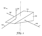
図1は、方向依存性の取出し効率を有する光取出し部の上面斜視図である。取出し部100は上面110と側面120とを有している。方向依存性の取出し効率の一例を提供するため、第1の入射光線130及び第2の入射光線140が示される。取出し部100を貫通する軸線が例証のために設けられており、取出し部100の方位配向の基準としている。
FIG. 1 is a top perspective view of a light extraction portion having direction-dependent extraction efficiency. The take-out
取出し部100の形状により、第1の入射光線130及び第2の入射光線140は異なる挙動を示すことがある。取出し部100は、例えば、取出し部100又はその内部の屈折率が、光導波路の屈折率よりも低いか又は(例えば、空気の場合)それよりも実質的に低いようにして、光導波路内に設けられた場合、上面110に対して大きい入射角を有する第1の入射光線130が、上面110で全反射するようにされてもよい。取出し部100を、基準軸が光導波路の厚さ寸法を表すように配向又は整列させたと仮定すると、反射された光線132は、光導波路内で全反射又は伝達されないように切り離され、光導波路を出てもよい。換言すれば、反射された光線132が取り出される。取出し部100の面上における入射光の相互作用は、取出し部の形状、及び取出し部と光導波路との間の相対反射率によって、モデル化され予測されてもよい。対照的に、第2の入射光線140は、非常に小さい入射角で、この例では法線に近い入射で、側面120に入射する。したがって、第2の入射光線140は取出し部100を通して伝送される。光導波路内で方向が大幅に変化しない伝送された光線142は、光導波路内に留まり、その中で伝達され続けてもよい。いくつかの実施形態では、第2の入射光線140は反射されてもよく、それでもなお光導波路内に留まり、場合によっては他の取出し部に入射する。
Depending on the shape of the
個々の取出し部の取出し効率は、少なくとも本出願の目的のため、取出し部に入射する光とその取出し部によって取り出される光の比として説明されてもよい。この特性は、(少なくとも妥当なサイズスケール内で)サイズに依存せず、形状に大きく依存することに留意されたい。個々の取出し部の合計取出し効率は、方位方向から取出し部に入射する光と入射角の比を説明する。また、光取出し部(特に、方位的に対称的な光取出し部)を、方向依存性の取出し効率を有するものとして特徴付けるのが有用なことがある。例えば、図1の取出し部は、第1の入射光線130の方位方向に沿って入射する光に対して第1の取出し効率を有してもよく、第2の入射光線140の方位方向に沿って入射する光に対して第2の実質的により低い取出し効率を有してもよい。別の観点から、光は、光が入射する取出し部の入力面に応じて、異なる効率で取り出されてもよい。第1の入射光線130及び第2の入射光線140は、実質的に直交し、取出し効率が著しく異なる事例を表す。多くの実施形態では、その代わりに、取出し効率は、より低い取出し効率からより高い取出し効率まで、かつその逆で、方位入射方向の関数として滑らかに又は連続的に変動してもよい。取出し部の効率はまた、同様に、入射極角の関数であってもよい。場合によっては、20°など、法線又は視認方向(図1の基準軸)から特定の角度内で取り出された光として、有用な取り出された光を特徴付けるのが有用なことがある。
The extraction efficiency of an individual extraction unit may be described as the ratio of the light incident on the extraction unit and the light extracted by that extraction unit, at least for the purposes of this application. Note that this property does not depend on size (at least within a reasonable size scale), but largely on shape. The total extraction efficiency of each extraction unit explains the ratio of the light incident on the extraction unit from the azimuth direction and the incident angle. It may also be useful to characterize the light extraction section (particularly the azimuthally symmetric light extraction section) as having direction-dependent extraction efficiency. For example, the extraction unit of FIG. 1 may have a first extraction efficiency for light incident along the azimuth direction of the first
取出し部100は、図1ではくさびとして描かれているが、その代わりに多くの好適な形状であってもよい。例えば、上面110などの面の形状は、正若しくは負の円筒状のサグを有するように設計又は構成されてもよい。光は、取出し角度又は視認方向の範囲内で取り出されてもよい。取出し部100の面、特に、図1の構成では上面110など、優先的に取り出す面の形状の変化は、取出し部100によって取り出される光から、視角範囲をシフトする、その幅を広くする、狭める、又は更には分割するものであってもよい。いくつかの実施形態では、取出し部100は、法線から20°の立体角など、視角範囲内の光を優先的に取り出すように設計されてもよい。取出し部100は、図1に示される例示の取出し部よりも短いか、薄いか、幅が広いか、又は長いものであってもよい。取出し部100は、多面的な面、湾曲面、凹状面、凸状面、球面、非球面、又はそれらの任意の組み合わせを有してもよい。取出し部100は、1つ以上の切頭の特徴又は面を有してもよい。切頭は、水平面、垂直面、又は他の何らかの面のいずれかに沿って生じてもよい。場合によっては、水平面に沿った切頭は合計取出し効率に影響することがあり、垂直面に沿った切頭は方位又は方向依存性の取出し効率に影響することがある。例示的な形状としては、くさび、正若しくは負の円筒状のサグを有するくさび、両凹のくさび(上面及び側面の両方としての凹状表面)、凹凸のくさび(上面及び側面の一方としての凹状表面、及び他方としての凸状表面)、非球面、断ち切られた若しくは切頭の非球面、又はその部分などが挙げられる。
The take-out
いくつかの実施形態では、図1のように、取出し部100は、より高い効率で光が取り出される1つの入力面を有してもよい。他の実施形態では、取出し部100は、より高い効率で光が取り出される複数の入力面を有してもよい。いくつかの実施形態では、取出し部100は滑らかな湾曲形状を有するので、面という用語は不適切なことがある。それでもなお、場合によっては、取出し部100のセグメント又は部分は、取出し部の他のセグメント又は部分よりも高い取出し効率を有することがある。いくつかの取出し部に関して、光路範囲に沿って光を優先的に取り出すものとしてそれらを特徴付けるのが適切である。光路範囲は、取出し部が特定の最小限の取出し効率を有する、入射光の角度範囲によって特徴付けられてもよい。この最小効率は、用途に応じて、入射光の50%、70%、80%、90%、95%、又は99%であってもよい。
In some embodiments, as shown in FIG. 1, the
取出し部100は任意の好適なサイズであってもよい。取出し部の効率は取出し部のサイズとは無関係であるが、取出し部のサイズは、その地点で取り出される光の合計強度に影響する。更に、人間の目による取出し部の分解性、スペックル効果、及び製造可能性などの設計上の考慮点は、取出し部の望ましく好適なサイズ又はサイズ範囲を決定する際の因子であり得る。
The take-out
図2は、方向依存性の取出し効率を備えた取出し部を含む光導波路を示す上面図である。光導波路200は、第1の光路範囲212を優先的に取り出す第1の取出し部210と、第2の光路範囲222を優先的に取り出す第2の取出し部220とを含む。本出願の目的のため、又は少なくとも本出願の図面の観点から、光路、又は最大取出し効率の入射方向に向けることによって、矢印が取出し配向を示すという慣例が採用される。取出し部と関連付けられた光路範囲は、最小取出し効率を越える取出し効率を有する経路を表す。取出し部の形状及び設計の詳細に応じて、関連する光路範囲は必ずしも連続範囲ではない。更に、図2は平面図なので光路範囲は二次元のみで表されるが、光路範囲は、やはり取出し部の形状を慎重に設計することによって制御される、三次元形状を有してもよい。
FIG. 2 is a top view showing an optical waveguide including an extraction portion having direction-dependent extraction efficiency. The
光導波路200は、光導波路の具体的な境界は重要でないことを示すため、点線の縁部で示されている。しかしながら、光導波路200は、アクリル材料、ポリマー材料、ガラスなどを含む、任意の好適な材料から作られてもよい。いくつかの実施形態では、光導波路200は取出し部と同じ材料片から形成され、取出し部は光導波路の窪み又は突出部である。
The
複製ツールを使用して、本明細書に記載の光導波路を作製してもよい。金属、シリコン、又は他の好適な材料を含んでもよい複製ツールは、突出した又は窪んだ光取出し部を含む光導波路の特徴のネガ型を含む。金属製の複製ツールは、ニッケルなどの金属をマスター型に電気メッキ又は電鋳した後、マスター型を取り外すことによって、マスター型から作られてもよい。シリコーン製の複製ツールは、シリコーン樹脂をマスター型に硬化させた後、マスター型を取り外すことによって作ることができる。 A replication tool may be used to make the optical waveguides described herein. Replicating tools, which may include metal, silicon, or other suitable material, include a negative type of optical waveguide feature that includes protruding or recessed light extractions. A metal replication tool may be made from a master mold by electroplating or electroforming a metal such as nickel onto the master mold and then removing the master mold. A silicone replication tool can be made by curing a silicone resin into a master mold and then removing the master mold.
マスター型は、例えば、本明細書に参照により組み込まれた、米国特許第7,941,013号(Marttilaら)に記載されている、多光子(又は具体的には、二光子)フォトリソグラフィープロセスを使用して形成されてもよい。多光子フォトリソグラフィープロセスは、少なくとも2つの光子を同時に吸収させるのに十分な光に光反応性組成物の少なくとも一部分を撮像的に露光させることを伴い、それによって、組成物が光で露光された場所で少なくとも1つの酸又はラジカル開始化学反応を誘発し、撮像的露光は、複数の光取出し構造の少なくとも表面を画成するのに有効なパターンで実施される。 The master mold is a multi-photon (or specifically two-photon) photolithography process described, for example, in US Pat. No. 7,941,013 (Martilla et al.), Incorporated herein by reference. May be used. The multiphoton photolithography process involves imagewise exposing at least a portion of the photoreactive composition to sufficient light to simultaneously absorb at least two photons, whereby the composition is exposed to light. Inducing at least one acid or radical-initiated chemical reaction at the location, the imaging exposure is performed in a pattern effective to define at least the surface of the plurality of light extraction structures.
第1の取出し部210及び第2の取出し部220は、同じ形状であってもよく、又は異なる形状であってもよい。所望の用途に応じて、取出し部は同様のサイズにされてもよく、又は異なるサイズを有してもよい。第1の取出し部210は、第1の光路範囲212に沿って光導波路内を伝播する光を優先的に取り出す。それに対応して、第2の取出し部220は、第2の光路範囲222に沿って光導波路内を伝播する光を優先的に取り出す。図2では、第2の取出し部220は、第1の光路範囲の少なくとも光路上に配設されている。
The
したがって、光導波路200内を伝播する光は、第2の取出し部220に入射する第1の光路範囲212内の光路の1つに沿って伝播してもよい。しかしながら、第2の取出し部220は、第1の光路範囲212内を伝播する光を優先的に取り出すように配向されていないので、その光は、第1の取出し部210に入射する光導波路200内を伝播する光よりも実質的に低い効率で取り出される。換言すれば、第1の光路範囲212内を伝播する光は、第1の取出し部210から取り出される第1の光路範囲212内を伝播する光よりも実質的に低い取出し効率で、第2の取出し部220から取り出される。いくつかの実施形態では、第1の光路範囲212内の光路に沿った光は実質的に、第2の取出し部220によって取り出されなくてもよく、第1の光路範囲212内の光路に沿った実質的に全ての光は、第1の取出し部210によって取り出されてもよい。
Therefore, the light propagating in the
図3は、縁部及び光源を含む、図2の光導波路を示す。光導波路300は、第1の光路範囲312を優先的に取り出す第1の取出し部310と、第2の光路範囲322を優先的に取り出す第2の取出し部320とを含む。光源330は、光導波路300の縁部に沿って、又は縁部位置に位置決めされている。光源は、第2の取出し部320及び第1の取出し部310の両方に入射する光線332を発生させる。図2のように、第2の取出し部320は、第1の取出し部310と関連付けられた第1の光路範囲312の少なくとも1つに沿って配設されている。
FIG. 3 shows the optical waveguide of FIG. 2 including an edge and a light source. The
光源330は、一般的な照明位置(又は、仮想画像若しくは反射光の場合は見かけの照明位置)であることが意図され、光導波路300の一般原理をより良く例証するために提供される。光源330は、円として描かれているが、任意の寸法範囲を有してもよく、LED、CCFL、若しくは白熱電球を含む、任意の好適な光源又は一組の光源であってもよい。いくつかの実施形態では、光源330は周辺光の光源であってもよく、又はそれを含んでもよい。光源330は、任意の波長若しくは波長範囲の光を放射するか、又は発生させてもよい。
The
光源330によって発生する光線332は、第1の光路範囲312の1つに沿って光導波路300内を伝播している。第2の取出し部320はその経路に沿って配設され、光線332は、第2の取出し部320の非優先的な取出し面に入射し、第2の光路範囲322の1つに沿って伝播していない。したがって、第2の取出し部320は、光線332を取り出すとしても、その取出し効率は低い。場合によっては、光線332は、著しく逸脱せずに第2の取出し部320を通って伝送される。いくつかの実施形態では、光線332は90%が伝送され10%が取り出されてもよく、取出し部形状の、特に1つ以上の非優先的な取出し面上における異なる設計は、異なる比率をもたらすであろう。次に、光線332は第1の取出し部310に、より具体的には第1の取出し部310の優先的な取出し面に入射し、高い取出し効率で、又は少なくとも、場合によっては、光源330からの同じ光線又は光路に対する第2の取出し部320の取出し効率よりも実質的に高い取出し効率で取り出されてもよい。
The
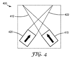
図4は、方向依存性の取出し効率を備えた取出し部を含む別の光導波路を示す上面図である。光導波路400は、第1の光路範囲412と関連付けられた第1の取出し部410と、第2の光路範囲422と関連付けられた第2の取出し部420とを含む。図4の構成では、第1の光路範囲412及び第2の光路範囲420の各光路は交差する。
FIG. 4 is a top view showing another optical waveguide including an extraction portion having direction-dependent extraction efficiency. The
図5は、光導波路の一般的な機能原理を理解するのを容易にするため、縁部及び光源を追加した、図4に示される光導波路の上面図である。光導波路500は、図4と同様に、第1の光路範囲512及び第2の光路範囲522とそれぞれ関連付けられた、第1の取出し部510及び第2の取出し部520を含む。光導波路500の縁部に沿って、又はそれに近接して、第1の光源530及び第2の光源540が配設される。図3と同様に、光源の形状及び正確な位置は、例証しやすくするために選択されたものであり、単なる例示の縁部位置を提供するものと理解されるべきである。
FIG. 5 is a top view of the optical waveguide shown in FIG. 4 with the addition of edges and light sources to facilitate an understanding of the general functional principles of the optical waveguide. Similar to FIG. 4, the
第1の縁部位置にある第1の光源530は、第1の光線532及び第2の光線534の両方を発生させる。第1の光線532は第1の光路範囲512の1つに沿って伝播し、第2の光線534は、第1の光路範囲512又は第2の光路範囲522のどちらに沿っても伝播していない。第1の光線532は、第1の取出し部510に入射し、特定の第1の取出し効率で取り出される。第2の光線534は、第2の取出し部520に入射し、第1の取出し効率よりも実質的に低い取出し効率で取り出される。
The first light source 530 at the first edge position generates both the
同様に、第2の縁部位置にある第2の光源540は、第3の光線542及び第4の光線544の両方を発生させる。第3の光線は第2の光路範囲522の1つに沿って伝播し、第4の光線544は、第1の光路範囲512又は第2の光路範囲522のどちらに沿っても伝播していない。第3の光線542は、第2の光取出し部520に入射し、特定の第2の取出し効率で取り出される。第4の光線544は、第1の取出し部510に入射し、第2の取出し効率よりも実質的に低い取出し効率で取り出される。
Similarly, the second
図5の構成に描かれる概念は、いくつかの実施形態では、光導波路500の特定の部分を選択的に照明するのに利用されることがある。例えば、第1の光源530からは光が来ているが第2の光源540からは来ていない(例えば、第1の光源530は電力供給されているが、第2の光源540は電力供給されていない)場合、第1の光源530と相対している第1の取出し部510の取出し効率が比較的高いので、取出し部は第2の取出し部520よりも多くの光を取り出す。それに対応して、第2の光源540からは光が来ているが第1の光源530からは来ていなければ、第2の取出し部520が第1の取出し部510よりも多くの光を取り出す。
The concept depicted in the configuration of FIG. 5 may be utilized in some embodiments to selectively illuminate specific portions of the
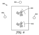
図6は、方向依存性の取出し効率を備えた取出し部のクラスタを含む光導波路を示す上面図である。光導波路600は、第1のクラスタ620と、第2のクラスタ630と、第1の光源640と、第2の光源650と、第3の光源660とを含む。光源は、説明しやすくするため、仮想の縁部位置を表すように配置されている。図6は、クラスタ内における光取出し部の優先的な方向を示すため、これまでの図面の慣例を採用しているが、例証しやすくするため、各取出し部と関連付けられた光路の範囲は示されていない。
FIG. 6 is a top view showing an optical waveguide including a cluster of extraction parts having direction-dependent extraction efficiency. The
第1のクラスタ620及び第2のクラスタ630は、同じ若しくは類似の数の光取出し部を有してもよく、又はそれぞれ異なる数の光取出し部を有してもよい。いくつかの実施形態では、第1のクラスタ620及び第2のクラスタ630内の取出し部のサイズ又は形状は、光導波路600内におけるそれらの位置を補償するように様々であってもよく、場合によっては、このばらつきは、取り出された光の均一性の助けとなってもよい。第1のクラスタ620及び第2のクラスタ630は、最小限の複数の光取出し部を有するが、任意の好適な数の光取出し部を有してもよい。いくつかの実施形態では、光取出し部のクラスタ内の各光取出し部は異なる配向を有してもよい。いくつかの実施形態では、光取出し部の各クラスタ内のいくつかの光取出し部は同じ配向を有してもよい。
The
光導波路600内のクラスタと例示の縁部位置に配設された光源との間の光学的相互作用は複雑であるため、これらの光源と個々の光取出し部それぞれ又は各クラスタとの間の光路を例証する例示の光線は提供されない。しかしながら、いくつかの実施形態では、クラスタ内の各取出し部に対するそれぞれの関連する光路範囲内の光路はいずれも互いに交差しない。いくつかの実施形態では、クラスタ内の2つの取出し部それぞれに対するそれぞれの関連する光路範囲内の光路はいずれも互いに交差しない。第1の光源640、第2の光源650、及び第3の光源660は、対象の光学効果を作り出すように選択的に駆動又は電力供給されてもよい。例えば、第1の光源640が駆動又は電力供給されて、光導波路600内に描かれている光取出し部のクラスタに入射する光を発生させた場合、クラスタ内の3つの取出し部は、異なる取出し効率で光を取り出してもよい。同様に、第1の光源640及び第2の光源650が光を発生させるようにされた場合、それら2つの光源からの光は、観察者にとっては、取出し部を有するクラスタが、第1の光源640及び第2の光源650それぞれの縁部位置から光導波路内を伝播する光を優先的に取り出すように、組み合わされて見えることがある。あるいは、第1の光源640及び第2の光源650の一方から、他方から、又はどちらからの光も、クラスタが、それらの方向からの光を優先的に取り出すように配向された光取出し部の一方又は両方を有さないように見えることがある。
Because the optical interaction between the clusters in the
この構成は、いくつかの実施形態では、第3の光源660(又はそれ以上)、並びに慎重な取出し部の設計及び光導波路600上におけるその配置と組み合わされて、情報の表示における大幅な設計上の柔軟性をもたらしてもよい。例えば、光源は選択的又は連続的に駆動されてもよく、光取出し部の各配向は光導波路内で異なるように分配されている。異なる全体的な取出しパターンは、光源の各縁部位置に関して異なる。例えば、特に全ての光源が同じ又は類似した色の光を放射する場合、光源それぞれを選択的に照明することが異なる効果をもたらすことがある。例えば、取出し部クラスタは、クラスタにわたる取出し部の配向の分布及び光源の縁部位置に応じて、多くの光、より少ない光、又はごくわずかな光を取り出してもよい。実際に、光源の選択的駆動は、別の方法では調光不能な光源の調光器として作用してもよい。2つ以上の光源が同様に同時に駆動されて、様々な輝度レベルに対してより一層の制御をもたらしてもよい。光源が異なる色であるか、又は異なる波長範囲を有する場合、光源を別個に駆動して、クラスタにおいて光源からの光を制御し予測可能に組み合わせることにより、異なる色の見た目を提供することができる。いくつかの実施形態では、クラスタにわたる取出し部の配向の分布は、光源の電力供給によって、別の方法では他の縁部位置からの照明の下では目に見えないか又は実質的に目に見えないであろう、画像、印、ロゴ、又はセキュリティ、検証、若しくは認証の特徴が現れるようにするものであってもよい。取出し部の各配向は、クラスタを通して分配されて、光源を循環させるとアニメーションを作るようにされてもよい。タイマー、マイクロプロセッサ、又は他の入力デバイスが、光源の照明を制御するのに使用されてもよい。いくつかの実施形態では、光源の照明、したがって特定の撮像的な取出し部パターンの見た目は、ユーザ入力を通してプログラム可能、切換え可能、又は別の方法で制御可能であってもよい。
This configuration, in some embodiments, in combination with a third light source 660 (or more), and careful extraction design and its placement on the
図7は、方向依存性の取出し効率を備えた取出し部のクラスタを含む別の光導波路の平面図である。光導波路700は、図6の光導波路600と同様に、第1の印710及び第2の印720としての同様に配向された光取出し部のクラスタを有する。また、縁部位置には、第1の光源740及び第2の光源750が位置決めされる。第1の光源740は第1の光線742及び第2の光線744を発生させる。第2の光源750は第3の光線752を発生させる。
FIG. 7 is a plan view of another optical waveguide including a cluster of extraction portions having direction-dependent extraction efficiency. Similar to the
光導波路700の破線は、光導波路700の特定の寸法を強調しない光導波路の破線を除いて、例証しやすくするために簡略化している印の近似的な境界を表す。同様に配向された光取出し部の配置を用いて、任意の好適なロゴ、形状、単語、又は他の印など、あらゆる形状又はサイズが可能である。光導波路700の動作は図6の光導波路600に類似しており、光は、方向依存性の光取出し部の配向及び光源の縁部位置に基づいて、異なるように取り出されている。例えば、第1の印710は第1の光源740からの光を第2の光線744として、第2の光源750からの光を第3の光線752として受け取る。しかしながら、第1の印710の取出し部は、第1の光源740からの光路に沿って光を優先的に取り出し、第2の光源750からの光路に沿った光は実質的に低い効率で取り出すように配向されている。したがって、例えば、第1の光源740が青色光を放射し、第2の光源750が赤色光を放射し、それら2つが同時に光を放射する場合、第1の印710は、赤色光よりもはるかに高い効率で青色光を取り出す。したがって、光導波路700の第1の印710に対応する部分は青く見える。
The dashed lines of the
同様に、第2の印720は、第1の光源740から第1の光線742として、第2の光源750から第3の光線752(少なくとも、第3の光線752の、第1の印710の取出し部によって方向転換されない又は取り出されない部分)として両方の光を受け取る。しかしながら、第2の印720の取出し部は、第1の光源740からの光路に沿った光よりもはるかに高い効率で、第2の光源750からの光路に沿って光を取り出すように構成される。したがって、第1の印710に関して仮想的に説明したものが第2の印720に適用されると、即ち、第1の光源740が青色光を放射し、第2の光源750が赤色光を放射すると、第2の印720は赤く見える。いくつかの実施形態では、光導波路700の取出し部の取出し特性が方向依存性であるため、光源が同時に駆動された場合、第1の印710は青く見えることがあり、第2の720は赤く見えることがあり、クロストーク又は混色はほとんどない。同様に、一方又は他方の印が、他方の特徴が実質的に目に見えないままで照明されてもよい。いくつかの実施形態では、光導波路上の全ての印は、第1の印710及び第2の印720など、重なり合わないセグメントで構成されている。図7に実質的に示されるように、重なり合わないセグメントと取出し部のクラスタとの間には、一対一の対応があってもよい。
Similarly, the
図8は、方向依存性の取出し効率を備えた取出し部を含む光導波路を示す上面図である。光導波路800は、この図では個別に分類又は特定されていない、様々な光取出し部を含む。更に、第1の光源810、第2の光源820、及び第3の光源830は、異なる縁部位置に配設されている。図6〜図7のように、各光源の縁部位置からの光は、光導波路800内の光取出し部の異なる部分集合を照明してもよい。このように、光導波路800は、光源からの光がどの縁部位置で生じるかに応じて、異なる画像、ロゴ、又は取出し部パターンが目に見えるように構成されていてもよい。取出し効率は必ずしも二元的(光導波路内で全ての光が取り出されるか、又は全ての光が伝送若しくは反射される)ではないため、取出し部は、2つ以上の縁部位置から中間の効率で光を取り出すように配向されていてもよい。
FIG. 8 is a top view showing an optical waveguide including an extraction portion having direction-dependent extraction efficiency. The
図9は、方向依存性の取出し効率を備えた取出し部を含む別の光導波路を示す上面図である。光導波路900は、個別に分類又は特定されていない複数の取出し部を含む。第1の光源910及び第2の光源920は異なる縁部位置に配設されている。図6〜図8と同様に、各光源の縁部位置からの光は、光導波路900内の光取出し部の異なる部分集合を照明してもよい。図9は重ね合わされたパターンを示す。例えば、第1の光源910からの光は、光導波路900の図示される部分にわたって実質的に均一な照明を提供してもよい。別の方法として、又はそれに加えて、第2の光源920からの光は、第2の光源920の縁部位置からの光を優先的に取り出すように、その光取出し部が配向されて示されている、部分集合のみに照明を提供してもよい。ある意味で、第1の光源910からの光は光導波路900の放射表面で第1の画像を形成し、第2の光源920からの光は光導波路の放射表面で第2の画像を形成する。この構成の用途としては、例えば、自動車の尾灯の場合、同時に又は別個に、異なる強度及びパターンで稼働させることができる、運行表示灯に重ね合わされる方向指示灯が挙げられる。他の用途、例えば、信号系、ランプ及び照明装置を含む一般照明又は装飾照明、選択的に照明することができる、サンルーフ、窓、及び天窓などの透明採光が想起され、本明細書に記載される光導波路及び構成を含んでもよい。更に、かかる用途は、別の方法として、又はそれに加えて、他の図面に関連して記載した要素、例えば図6〜図8に記載した要素を含んでもよい。
FIG. 9 is a top view showing another optical waveguide including an extraction portion having direction-dependent extraction efficiency. The
図面中の要素に関する記載は、特段の指示がない限り、他の図面中の対応する要素に対して等しく適用されることが理解されるべきである。上述した特定の実施形態は、本発明の様々な態様の説明を容易にするために詳細に記載したものであるので、本発明はかかる実施形態に限定されるものと見なされるべきではない。むしろ、本発明は、添付の特許請求の範囲及びその等価物によって定義される本発明の範囲内に該当する様々な修正、等価のプロセス、及び代替のデバイスを含む、本発明の全ての態様を網羅するものとして理解されるべきである。 It should be understood that the description of elements in the drawings applies equally to corresponding elements in the other drawings unless otherwise indicated. Since the particular embodiments described above have been described in detail in order to facilitate describing various aspects of the invention, the invention should not be construed as limited to such embodiments. Rather, the invention is intended to cover all aspects of the invention, including various modifications, equivalent processes, and alternative devices falling within the scope of the invention as defined by the appended claims and their equivalents. It should be understood as an exhaustive one.
Claims (20)
第1及び第2の光路範囲それぞれに沿って前記光導波路内を伝播する光線を受け取ると光を優先的に取り出すように構成された、第1及び第2の個別の離隔された光取出し部を備える前記光導波路であって、前記優先的に取り出された光線が、最小限の第1及び第2の取出し効率それぞれで視角範囲に沿って前記光導波路を出て、前記第2の光取出し部が、前記第1の光路範囲内の第1の光路上に配設されており、前記第1の光路に沿って伝播し、かつ前記第2の光取出し部によって取り出された光線が、前記最小限の第1の取出し効率よりも実質的に低い第3の取出し効率で前記視角範囲内で前記光導波路を出る、光導波路。 Disposed on the main surface of the optical waveguide;
First and second separate spaced light extraction portions configured to preferentially extract light upon receipt of light propagating through the optical waveguide along first and second optical path ranges, respectively; The optical waveguide is provided, wherein the preferentially extracted light beam exits the optical waveguide along a viewing angle range with the minimum first and second extraction efficiencies, and the second light extraction unit. Is disposed on the first optical path within the first optical path range, the light beam propagating along the first optical path and extracted by the second light extraction unit is An optical waveguide exiting the optical waveguide within the viewing angle range with a third extraction efficiency that is substantially lower than a limited first extraction efficiency.
Applications Claiming Priority (3)
| Application Number | Priority Date | Filing Date | Title |
|---|---|---|---|
| US201361922217P | 2013-12-31 | 2013-12-31 | |
| US61/922,217 | 2013-12-31 | ||
| PCT/US2014/072649 WO2015103188A1 (en) | 2013-12-31 | 2014-12-30 | Lightguide including extractors with directionally dependent extraction efficiency |
Publications (2)
| Publication Number | Publication Date |
|---|---|
| JP2017503321A true JP2017503321A (en) | 2017-01-26 |
| JP2017503321A5 JP2017503321A5 (en) | 2018-02-15 |
Family
ID=53493963
Family Applications (1)
| Application Number | Title | Priority Date | Filing Date |
|---|---|---|---|
| JP2016543632A Pending JP2017503321A (en) | 2013-12-31 | 2014-12-30 | Optical waveguide with extraction part with direction-dependent extraction efficiency |
Country Status (7)
| Country | Link |
|---|---|
| US (1) | US20160299280A1 (en) |
| EP (1) | EP3090293A4 (en) |
| JP (1) | JP2017503321A (en) |
| KR (1) | KR20160105455A (en) |
| CN (1) | CN105849604A (en) |
| CA (1) | CA2935238A1 (en) |
| WO (1) | WO2015103188A1 (en) |
Cited By (1)
| Publication number | Priority date | Publication date | Assignee | Title |
|---|---|---|---|---|
| JP7054882B2 (en) | 2017-11-21 | 2022-04-15 | パナソニックIpマネジメント株式会社 | Display device |
Families Citing this family (3)
| Publication number | Priority date | Publication date | Assignee | Title |
|---|---|---|---|---|
| JP6406053B2 (en) * | 2015-02-24 | 2018-10-17 | オムロン株式会社 | Light guide and light emitting device |
| EP3674603A1 (en) * | 2018-12-27 | 2020-07-01 | Marelli Automotive Lighting Italy S.p.A. | Lighting and/or signaling device for vehicles |
| DE102020121008B4 (en) | 2020-08-10 | 2022-02-17 | Dr. Ing. H.C. F. Porsche Aktiengesellschaft | motor vehicle rear light |
Citations (5)
| Publication number | Priority date | Publication date | Assignee | Title |
|---|---|---|---|---|
| US20100254158A1 (en) * | 2009-04-01 | 2010-10-07 | Motorola, Inc. | Visual Morphing Using Directionally Selective Microprisms |
| JP2011198468A (en) * | 2010-03-17 | 2011-10-06 | Sharp Corp | Backlight unit, and image display device using the same |
| US20120051088A1 (en) * | 2010-08-25 | 2012-03-01 | Qualcomm Mems Technologies, Inc. | Methods of manufacturing illumination systems |
| US20130182457A1 (en) * | 2012-01-13 | 2013-07-18 | Rambus Inc. | Lighting assembly with static autostereoscopic image output |
| WO2013180725A1 (en) * | 2012-05-31 | 2013-12-05 | Hewlett-Packard Development Company, L.P. | Directional backlight |
Family Cites Families (5)
| Publication number | Priority date | Publication date | Assignee | Title |
|---|---|---|---|---|
| US7277609B2 (en) * | 2004-11-05 | 2007-10-02 | Optical Research Associates | Methods for manipulating light extraction from a light guide |
| JP5951928B2 (en) * | 2007-09-06 | 2016-07-13 | スリーエム イノベイティブ プロパティズ カンパニー | Light guide with light extraction structure to provide area control of light output |
| US8851734B2 (en) * | 2008-03-27 | 2014-10-07 | Skc Haas Display Films Co., Ltd. | Light guiding film having light extraction features |
| EP2370854B1 (en) * | 2008-12-18 | 2016-09-28 | 3M Innovative Properties Company | Lightguides having enhanced light extraction |
| JP5624617B2 (en) * | 2009-06-29 | 2014-11-12 | スリーエム イノベイティブプロパティズカンパニー | Light guide and light source incorporating the light guide |
-
2014
- 2014-12-30 US US15/036,334 patent/US20160299280A1/en not_active Abandoned
- 2014-12-30 CN CN201480071580.1A patent/CN105849604A/en active Pending
- 2014-12-30 KR KR1020167020575A patent/KR20160105455A/en not_active Application Discontinuation
- 2014-12-30 EP EP14876212.3A patent/EP3090293A4/en not_active Withdrawn
- 2014-12-30 JP JP2016543632A patent/JP2017503321A/en active Pending
- 2014-12-30 WO PCT/US2014/072649 patent/WO2015103188A1/en active Application Filing
- 2014-12-30 CA CA2935238A patent/CA2935238A1/en not_active Abandoned
Patent Citations (5)
| Publication number | Priority date | Publication date | Assignee | Title |
|---|---|---|---|---|
| US20100254158A1 (en) * | 2009-04-01 | 2010-10-07 | Motorola, Inc. | Visual Morphing Using Directionally Selective Microprisms |
| JP2011198468A (en) * | 2010-03-17 | 2011-10-06 | Sharp Corp | Backlight unit, and image display device using the same |
| US20120051088A1 (en) * | 2010-08-25 | 2012-03-01 | Qualcomm Mems Technologies, Inc. | Methods of manufacturing illumination systems |
| US20130182457A1 (en) * | 2012-01-13 | 2013-07-18 | Rambus Inc. | Lighting assembly with static autostereoscopic image output |
| WO2013180725A1 (en) * | 2012-05-31 | 2013-12-05 | Hewlett-Packard Development Company, L.P. | Directional backlight |
Cited By (1)
| Publication number | Priority date | Publication date | Assignee | Title |
|---|---|---|---|---|
| JP7054882B2 (en) | 2017-11-21 | 2022-04-15 | パナソニックIpマネジメント株式会社 | Display device |
Also Published As
| Publication number | Publication date |
|---|---|
| KR20160105455A (en) | 2016-09-06 |
| US20160299280A1 (en) | 2016-10-13 |
| EP3090293A4 (en) | 2017-08-09 |
| CA2935238A1 (en) | 2015-07-09 |
| CN105849604A (en) | 2016-08-10 |
| EP3090293A1 (en) | 2016-11-09 |
| WO2015103188A1 (en) | 2015-07-09 |
Similar Documents
| Publication | Publication Date | Title |
|---|---|---|
| CN104903148B (en) | Hybrid taillight product | |
| CN105190369B (en) | Two-sided film with split type optical scattering structure | |
| US4922384A (en) | Illuminated display with half-silvered mirrors and discrete refractor plates | |
| CN103597273B (en) | In the panel have lining cave in have the edge-illuminated type illumination panel of lower shot-light | |
| US20060083476A1 (en) | Optical device with dual function of illumination and forming a figurative image | |
| MX2014011764A (en) | Edge-lit flat panel repetitive lighting fixture. | |
| CN104884307A (en) | Stacked lightguide tailight article | |
| JP2003519810A (en) | Lighting device and light emitting panel | |
| CN104748072B (en) | Use the lighting device of linear beam | |
| EP3149400B1 (en) | Tunable daylight experience using micro faceted foils | |
| JP2018097942A (en) | Light guide plate, display device, and game machine | |
| US9766390B2 (en) | Optical member having three-dimensional effect forming portion and multiple effect forming portion and lighting device using the same | |
| CN108431671B (en) | 3D display device | |
| JP2017503321A (en) | Optical waveguide with extraction part with direction-dependent extraction efficiency | |
| US20210018159A1 (en) | Lighting system for outdoor lighting | |
| JP2011244930A (en) | Game machine equipped with decoration device | |
| CN103201654A (en) | Rotated micro-optical structures for banding suppression from point light sources | |
| US20150043220A1 (en) | Using micro optical elements for depth perception in luminescent figurative structures illuminated by point sources | |
| TW201409096A (en) | Modular micro-structured light-guiding device | |
| EP3921573B1 (en) | A lighting device | |
| US10876712B2 (en) | Comfort of outdoor luminaires due to phyllotactic arrangement of LED sources | |
| JP2011247993A (en) | Decoration device | |
| JP5310482B2 (en) | Lighting device | |
| JP6072699B2 (en) | Lighting device | |
| WO2019214006A1 (en) | Vehicle light providing three-dimensional lighting effect and vehicle |
Legal Events
| Date | Code | Title | Description |
|---|---|---|---|
| A521 | Request for written amendment filed |
Free format text: JAPANESE INTERMEDIATE CODE: A523 Effective date: 20171227 |
|
| A621 | Written request for application examination |
Free format text: JAPANESE INTERMEDIATE CODE: A621 Effective date: 20171227 |
|
| A977 | Report on retrieval |
Free format text: JAPANESE INTERMEDIATE CODE: A971007 Effective date: 20180824 |
|
| A131 | Notification of reasons for refusal |
Free format text: JAPANESE INTERMEDIATE CODE: A131 Effective date: 20180904 |
|
| A02 | Decision of refusal |
Free format text: JAPANESE INTERMEDIATE CODE: A02 Effective date: 20190326 |