JP2017503128A - Check valve with improved seal - Google Patents
Check valve with improved seal Download PDFInfo
- Publication number
- JP2017503128A JP2017503128A JP2016544150A JP2016544150A JP2017503128A JP 2017503128 A JP2017503128 A JP 2017503128A JP 2016544150 A JP2016544150 A JP 2016544150A JP 2016544150 A JP2016544150 A JP 2016544150A JP 2017503128 A JP2017503128 A JP 2017503128A
- Authority
- JP
- Japan
- Prior art keywords
- check valve
- seal member
- valve according
- port
- internal cavity
- Prior art date
- Legal status (The legal status is an assumption and is not a legal conclusion. Google has not performed a legal analysis and makes no representation as to the accuracy of the status listed.)
- Granted
Links
Images


Classifications
-
- F—MECHANICAL ENGINEERING; LIGHTING; HEATING; WEAPONS; BLASTING
- F16—ENGINEERING ELEMENTS AND UNITS; GENERAL MEASURES FOR PRODUCING AND MAINTAINING EFFECTIVE FUNCTIONING OF MACHINES OR INSTALLATIONS; THERMAL INSULATION IN GENERAL
- F16K—VALVES; TAPS; COCKS; ACTUATING-FLOATS; DEVICES FOR VENTING OR AERATING
- F16K15/00—Check valves
- F16K15/02—Check valves with guided rigid valve members
- F16K15/06—Check valves with guided rigid valve members with guided stems
-
- F—MECHANICAL ENGINEERING; LIGHTING; HEATING; WEAPONS; BLASTING
- F04—POSITIVE - DISPLACEMENT MACHINES FOR LIQUIDS; PUMPS FOR LIQUIDS OR ELASTIC FLUIDS
- F04F—PUMPING OF FLUID BY DIRECT CONTACT OF ANOTHER FLUID OR BY USING INERTIA OF FLUID TO BE PUMPED; SIPHONS
- F04F5/00—Jet pumps, i.e. devices in which flow is induced by pressure drop caused by velocity of another fluid flow
- F04F5/14—Jet pumps, i.e. devices in which flow is induced by pressure drop caused by velocity of another fluid flow the inducing fluid being elastic fluid
- F04F5/16—Jet pumps, i.e. devices in which flow is induced by pressure drop caused by velocity of another fluid flow the inducing fluid being elastic fluid displacing elastic fluids
- F04F5/20—Jet pumps, i.e. devices in which flow is induced by pressure drop caused by velocity of another fluid flow the inducing fluid being elastic fluid displacing elastic fluids for evacuating
- F04F5/22—Jet pumps, i.e. devices in which flow is induced by pressure drop caused by velocity of another fluid flow the inducing fluid being elastic fluid displacing elastic fluids for evacuating of multi-stage type
-
- F—MECHANICAL ENGINEERING; LIGHTING; HEATING; WEAPONS; BLASTING
- F04—POSITIVE - DISPLACEMENT MACHINES FOR LIQUIDS; PUMPS FOR LIQUIDS OR ELASTIC FLUIDS
- F04F—PUMPING OF FLUID BY DIRECT CONTACT OF ANOTHER FLUID OR BY USING INERTIA OF FLUID TO BE PUMPED; SIPHONS
- F04F5/00—Jet pumps, i.e. devices in which flow is induced by pressure drop caused by velocity of another fluid flow
- F04F5/44—Component parts, details, or accessories not provided for in, or of interest apart from, groups F04F5/02 - F04F5/42
- F04F5/46—Arrangements of nozzles
- F04F5/467—Arrangements of nozzles with a plurality of nozzles arranged in series
-
- F—MECHANICAL ENGINEERING; LIGHTING; HEATING; WEAPONS; BLASTING
- F04—POSITIVE - DISPLACEMENT MACHINES FOR LIQUIDS; PUMPS FOR LIQUIDS OR ELASTIC FLUIDS
- F04F—PUMPING OF FLUID BY DIRECT CONTACT OF ANOTHER FLUID OR BY USING INERTIA OF FLUID TO BE PUMPED; SIPHONS
- F04F5/00—Jet pumps, i.e. devices in which flow is induced by pressure drop caused by velocity of another fluid flow
- F04F5/54—Installations characterised by use of jet pumps, e.g. combinations of two or more jet pumps of different type
-
- F—MECHANICAL ENGINEERING; LIGHTING; HEATING; WEAPONS; BLASTING
- F16—ENGINEERING ELEMENTS AND UNITS; GENERAL MEASURES FOR PRODUCING AND MAINTAINING EFFECTIVE FUNCTIONING OF MACHINES OR INSTALLATIONS; THERMAL INSULATION IN GENERAL
- F16K—VALVES; TAPS; COCKS; ACTUATING-FLOATS; DEVICES FOR VENTING OR AERATING
- F16K15/00—Check valves
- F16K15/02—Check valves with guided rigid valve members
- F16K15/021—Check valves with guided rigid valve members the valve member being a movable body around which the medium flows when the valve is open
- F16K15/023—Check valves with guided rigid valve members the valve member being a movable body around which the medium flows when the valve is open the valve member consisting only of a predominantly disc-shaped flat element
-
- F—MECHANICAL ENGINEERING; LIGHTING; HEATING; WEAPONS; BLASTING
- F16—ENGINEERING ELEMENTS AND UNITS; GENERAL MEASURES FOR PRODUCING AND MAINTAINING EFFECTIVE FUNCTIONING OF MACHINES OR INSTALLATIONS; THERMAL INSULATION IN GENERAL
- F16K—VALVES; TAPS; COCKS; ACTUATING-FLOATS; DEVICES FOR VENTING OR AERATING
- F16K25/00—Details relating to contact between valve members and seat
- F16K25/005—Particular materials for seats or closure elements
-
- F—MECHANICAL ENGINEERING; LIGHTING; HEATING; WEAPONS; BLASTING
- F16—ENGINEERING ELEMENTS AND UNITS; GENERAL MEASURES FOR PRODUCING AND MAINTAINING EFFECTIVE FUNCTIONING OF MACHINES OR INSTALLATIONS; THERMAL INSULATION IN GENERAL
- F16K—VALVES; TAPS; COCKS; ACTUATING-FLOATS; DEVICES FOR VENTING OR AERATING
- F16K27/00—Construction of housing; Use of materials therefor
- F16K27/02—Construction of housing; Use of materials therefor of lift valves
- F16K27/0209—Check valves or pivoted valves
-
- Y—GENERAL TAGGING OF NEW TECHNOLOGICAL DEVELOPMENTS; GENERAL TAGGING OF CROSS-SECTIONAL TECHNOLOGIES SPANNING OVER SEVERAL SECTIONS OF THE IPC; TECHNICAL SUBJECTS COVERED BY FORMER USPC CROSS-REFERENCE ART COLLECTIONS [XRACs] AND DIGESTS
- Y10—TECHNICAL SUBJECTS COVERED BY FORMER USPC
- Y10T—TECHNICAL SUBJECTS COVERED BY FORMER US CLASSIFICATION
- Y10T137/00—Fluid handling
- Y10T137/7722—Line condition change responsive valves
- Y10T137/7837—Direct response valves [i.e., check valve type]
- Y10T137/7904—Reciprocating valves
- Y10T137/7908—Weight biased
- Y10T137/7909—Valve body is the weight
- Y10T137/7913—Guided head
- Y10T137/7915—Guide stem
Abstract
アスピレータ内に含まれたチェックバルブであって、第1のポート及び第2のポートを有する、内部キャビティを規定するハウジングであって、第1のポート及び第2のポート双方が内部キャビティと流体連通している、ハウジングと、内部キャビティ内のシール部材と、を含むチェックバルブを含むチェックバルブが、開示されている。シール部材が、ハウジングの内部キャビティ内の第1のシートに接触する閉鎖位置と、ハウジングの内部キャビティ内の第2のシートに接触する開放位置と、の間で並進可能である。シール部材が、シール部材が閉鎖位置にあるときに第1のシートとシール係合するために位置決めされたシール材料と、シール部材が開放位置にあるときに第2のシートと係合するために位置決めされた補強部材と、を有している。A check valve included in an aspirator having a first port and a second port defining an internal cavity, wherein both the first port and the second port are in fluid communication with the internal cavity. A check valve is disclosed that includes a check valve that includes a housing and a seal member within an internal cavity. The seal member is translatable between a closed position in contact with the first sheet in the internal cavity of the housing and an open position in contact with the second sheet in the internal cavity of the housing. A sealing member positioned for sealing engagement with the first sheet when the sealing member is in the closed position and for engaging the second sheet when the sealing member is in the open position; A positioned reinforcing member.
Description
(関連出願)
本出願は、2014年1月20日付けで出願された米国仮出願番号第61/929,264号の利益を主張するものであり、当該出願の全体は、参照することによって本明細書に組み込まれる。
(Related application)
This application claims the benefit of US Provisional Application No. 61 / 929,264, filed Jan. 20, 2014, which is hereby incorporated by reference in its entirety. It is.
(技術分野)
本出願は、エンジンシステムで、例えば内燃機関で使用するためのチェックバルブに関し、より具体的に改良型シール部材を有するチェックバルブに関する。
(Technical field)
This application relates to a check valve for use in an engine system, for example, an internal combustion engine, and more specifically to a check valve having an improved seal member.
エンジン、例えば自動車エンジンは、長期にわたってアスピレータ及び/又はチェックバルブを含んできた。概して、アスピレータは、エンジン空気のいくらかをベンチュリを通って移動させるように促すことによってエンジンマニホルドの真空よりも低い真空を作り出すために使用される。アスピレータが、その中にチェックバルブを含んでいるか、又はシステムが、独立したチェックバルブを含んでいる。チェックバルブが独立している場合、それらチェックバルブは、概して真空源と真空を使用する装置との間で下流に含まれる。 Engines, such as automobile engines, have long included aspirators and / or check valves. Generally, aspirators are used to create a vacuum lower than the engine manifold vacuum by encouraging some of the engine air to move through the venturi. The aspirator includes a check valve therein or the system includes an independent check valve. If check valves are independent, they are generally included downstream between the vacuum source and the device using the vacuum.
ブレーキブーストシステムを有するエンジンでは、チェックバルブが効率的にシールすることが困難な状況が存在する。これは望ましくなく、より効率的なシールを提供するために新たなチェックバルブが必要とされている。 In engines with a brake boost system, there are situations where it is difficult for the check valve to seal efficiently. This is undesirable and a new check valve is needed to provide a more efficient seal.
一側面では、流体連通システム内、例えば内燃機関の流体連通システム内に接続可能なチェックバルブユニットが、開示されている。一実施形態では、チェックバルブは、第1のポート及び第2のポートを有する、内部キャビティを規定するハウジングであって、第1のポート及び第2のポート双方が、内部キャビティと流体連通している、ハウジングと、キャビティ内のシール部材と、を含んでいる。シール部材は、ハウジングの内部キャビティ内の第1のシートに接触する閉鎖位置と、ハウジングの内部キャビティ内の第2のシートに接触する開放位置と、の間で並進可能である。シール部材は、シール部材が閉鎖位置にあるときに第1のシートとシール係合するために位置決めされたシール材料と、シール部材が開放位置にあるときに第2のシートと係合するために位置決めされた補強部材と、を有している。第2のシートは、内部キャビティ内に延在する、径方向に離間した複数のフィンガーであってもよい。第1のシートは、内部キャビティと第1のポートとの間で流体連通するためにハウジングによって規定された開口部を囲む第1の環状シールビードを含んでもよい。シール部材は、約1.0kPagから約6.0kPagの圧力変化を受けて閉鎖位置でシールする。 In one aspect, a check valve unit is disclosed that is connectable within a fluid communication system, eg, a fluid communication system of an internal combustion engine. In one embodiment, the check valve is a housing defining an internal cavity having a first port and a second port, wherein both the first port and the second port are in fluid communication with the internal cavity. A housing and a sealing member in the cavity. The seal member is translatable between a closed position that contacts a first sheet in the interior cavity of the housing and an open position that contacts a second sheet in the interior cavity of the housing. The seal member is positioned for sealing engagement with the first sheet when the seal member is in the closed position and for engaging the second sheet when the seal member is in the open position. A positioned reinforcing member. The second sheet may be a plurality of radially spaced fingers extending into the internal cavity. The first seat may include a first annular seal bead surrounding an opening defined by the housing for fluid communication between the internal cavity and the first port. The seal member seals in the closed position under a pressure change of about 1.0 kPag to about 6.0 kPag.
一実施形態では、補強部材は、シール材料の外面に取り付けられているか、又はシール材料に包み込まれている。別の実施形態では、シール材料は、補強部材の一部分上にオーバーモールドされている。組み立てられると、シール部材の補強材料は、第1の環状シールビードの位置に対して上方に、径方向内側に位置決めされている。一実施形態では、このように位置決めされた補強材料により、第1のシートは、第1の環状シールビードの径方向内側に配置された第2の環状シールビードを含んでもよい。ここで、補強材料は、第1の環状シールビード及び第2の環状シールビード双方の上方に位置決めされ、且つ第2の環状シールビードの位置に対してさらに径方向外側にある。 In one embodiment, the reinforcing member is attached to the outer surface of the sealing material or encased in the sealing material. In another embodiment, the sealing material is overmolded on a portion of the reinforcing member. When assembled, the reinforcing material of the seal member is positioned radially inward and above the position of the first annular seal bead. In one embodiment, with the reinforcing material positioned in this manner, the first sheet may include a second annular seal bead disposed radially inward of the first annular seal bead. Here, the reinforcing material is positioned above both the first annular seal bead and the second annular seal bead and is further radially outward relative to the position of the second annular seal bead.
一側面では、補強部材の幅は、シール部材と係合する第2のシートの一部分の寸法に比例している。補強部材が材料のリングである場合、幅は、材料のリングにおける内径と外径との間の差である。 In one aspect, the width of the reinforcing member is proportional to the size of the portion of the second sheet that engages the seal member. If the reinforcing member is a ring of material, the width is the difference between the inner and outer diameters of the ring of material.
一実施形態では、ハウジングは、ピンを含み、シール部材は、シール部材を貫通する孔を含んでもよい。チェックバルブが組み立てられると、ハウジングのピンは、ピンに沿ってシール部材を並進させるためにシール部材の孔内に収容される。 In one embodiment, the housing may include a pin and the seal member may include a hole through the seal member. When the check valve is assembled, the housing pins are received in the holes in the seal member to translate the seal member along the pins.
別の実施形態では、ハウジングは、シール部材の外縁周りに位置決めされた1つ以上のガイドを含んでもよく、シール部材は、その外縁に、1つ以上のガイドと整列する溝を含んでもよい。 In another embodiment, the housing may include one or more guides positioned around the outer edge of the seal member, and the seal member may include a groove in the outer edge that aligns with the one or more guides.
別の側面では、上述した補強部材を有するシール部材を有するチェックバルブをその中に含むアスピレータが、開示されている。用語“アスピレータ”の使用は、限定して解釈されるよう意図されず、且つベンチュリ間隙を有する装置を含んでおり、このベンチュリ間隙は、原動力流として大気圧で動作するか、又は原動力流として大気圧よりも高い圧力、例えばターボチャージャからのブースト空気で動作する。チェックバルブは、ベンチュリ間隙と整列させられた吸引ポートを通る流量を制御するためにアスピレータ内に位置決めされてもよい。一実施形態では、アスピレータは、ベンチュリ間隙から下流のバイパスを通る流量を制御する第2のチェックバルブを含む。第2のチェックバルブは、上述した補強部材を有するシール部材を有してもよい。 In another aspect, an aspirator is disclosed that includes a check valve having a seal member having a reinforcing member as described above. The use of the term “aspirator” is not intended to be construed in a limited way, and includes devices having a venturi gap that operates at atmospheric pressure as the motive flow or is largely as the motive flow. Operates at a pressure higher than atmospheric pressure, for example boost air from a turbocharger. A check valve may be positioned in the aspirator to control the flow rate through the suction port aligned with the venturi gap. In one embodiment, the aspirator includes a second check valve that controls the flow rate through the bypass downstream from the venturi gap. The second check valve may include a seal member having the reinforcing member described above.
以下の詳細な説明は、本発明の全体的な原理を示し、本発明の例は、添付の図面でさらに示される。図面では、同様の参照符号は、同一の又は機能的に類似する要素を示す。 The following detailed description illustrates the general principles of the invention and examples of the invention are further illustrated in the accompanying drawings. In the drawings, like reference numbers indicate identical or functionally similar elements.
本明細書で使用される“流体”は、任意の液体、懸濁液、コロイド、ガス、プラズマ又はそれらの組み合わせを意味する。 As used herein, “fluid” means any liquid, suspension, colloid, gas, plasma, or combination thereof.
図1及び図2は、ハウジング14を含むチェックバルブ10を開示し、ハウジング14は、内部キャビティ16を規定し、且つ内部キャビティ16と流体連通した第1のポート22と、内部キャビティ16と流体連通した第2の流体ポート24と、を規定し、内部キャビティ16は、その内部に、シール部材20が着座させられたピン18を有している。ハウジング14は、部品が流体密封シールしてともに接続された、多数の部品からなるハウジングである。内部キャビティ16は、第1のポート22及び第2のポート24よりも大きな寸法を概して有している。示す実施形態では、第1のポート22及び第2のポート24は、シール部材20が存在しない場合にチェックバルブ10を通る全体的に直線形の流路を規定するために互いに反対側に位置決めされているが、この形態に限定されない。別の実施形態では、第1のポート及び流体ポートは、互いに対して180°よりも小さい角度で位置決めされてもよい。内部キャビティ16を規定するハウジング14の一部分は、チェックバルブが“閉鎖している”ときにシール部材20が着座する第1の内部シート26と、チェックバルブが“開放している”ときにシール部材が着座する第2のシート28と、を含んでいる。図2では、第2のシート28は、第2のポート24により近接した内部キャビティ16の内面から内部キャビティ16内に延在する、径方向に間隔をあけられた複数のフィンガー30である。
FIGS. 1 and 2 disclose a
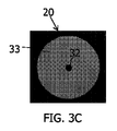
内部キャビティ16内を見る平面図が、図3Aに示してある。図3Aでは、ピン18が、内部キャビティ16内で中央に位置決めされて見え、且つ複数のアーム36が、ピン18から径方向外側に延在し、これにより、内部キャビティ内につながる流路を複数の導管38に分割して、チェックバルブ10が開放位置にあるときにシール部材20の外縁周りに流体流れを向ける。図3Bでは、シール部材20は、図3Aの内部キャビティ16内でピン上に設置されている。見ることができるように、補強部材34が、見ている人に向かって上方に面し、これは、完全に組み立てられたチェックバルブ10において第2のポート24に向かっている。
A plan view looking inside the
シール部材20は、特にエンジン内のブレーキブーストシステムにおいて性能を改善するために補強されている。図3Bから図3Dで見ることができるシール部材20は、シール材料33及び補強部材34を含んでいる。示す実施形態は、ピン18を収容するために全体的に中心の孔32を有しているが、これに限定されない。別の実施形態(図示せず)では、1つ以上のガイドが、シール部材20の外縁周りに位置決めされ、且つシール部材は、ガイドを収容する溝を含んでいるか又は含んでいなくてもよい。補強部材34は、第2のシート28に面するシール部材20の外面21に取り付けられているか、シール材料33によって少なくとも部分的にオーバーモールドされているか、又はシール材料33内に包み込まれている。補強部材34は、シール部材20が、大きな圧力変化を経験するときに、離間した複数のフィンガー30の間での押し出しに耐えることを可能にする。一実施形態では、補強部材34は、ちょうど説明したフィンガー30の間での押し出しにシール部材20が耐えることを可能にする剛性を有する金属であるか、又はこのような金属を含んでいる。本明細書で使用される“金属”は、純金属、金属合金、金属複合材、及び適切な剛性を有するこれらの組み合わせであるすべての材料を表すために総称的に使用される。別の実施形態では、補強部材34は、ガラス及び無機物などで充填されているか又は充填されていない(概して体積で30%)、カーボンファイバー又はプラスチック、例えばナイロンもしくはアセチルである。
補強部材34は、材料のリング、例えば上述した材料のリングである。リングは、内径及び外径を有している。本明細書で使用されるリングの幅W(図3D)は、内径と外径との間の差である。リングの幅Wは、開放位置にあるときにシール部材20に安定性を提供するために、第2のシート28に比例している。チェックバルブ10において、幅は、通常、約1mmから約10mmである。別の実施形態では、チェックバルブの幅は、約2mmから約4mmである。補強材料のリングは、厚さも有している。厚さは、約0.05mmから約1.00mmであるが、別の実施形態では、0.02mmから約0.5mmであってもよい。概して、補強材料34は、外側シールビード42及び外側シール材料33の内側にあるが、これに限定されない。また、補強部材34は、概して、内側シールビード44の外側及び(穴が存在する場合)シール材料33における孔32の外側にあるが、これに限定されない。内側ガイドピン18があってもなくてもよく、従って、シール材料33上に中心孔32が必須ではないことに留意されたい。第2のシート28は、補強材料34の幅Wの内側のどこかに並ぶことが好ましい。
The reinforcing
一実施形態のチェックバルブ10は、ブレーキブーストシステム内に含まれるためのものであり、且つ極めて小さい圧力変化、例えば約1.0kPagから6.0kPag又はより具体的に約2.4kPagから約4.4kPagの圧力変化でシールするが、大きい圧力変化、例えば約500kPagから約2500kPag又はより具体的に約1000kPagから約1800kPagの圧力変化に耐えることができる。さらに、補強部材34の付加は、チェックバルブの漏出速度を改善させる。漏出速度は、約0.2cc/minから約2cc/min又はより具体的に約0.3cc/minから約0.7cc/minである。
The
図4は、エンジンで、例えば自動車のエンジンで使用するための、全体として参照符号100で特定されたアスピレータ−チェックバルブ組立体の外観図である。エンジンは、真空を必要とする装置を含む内燃機関である。チェックバルブは、通常、全混合ポートで、通常キャブレター又は燃料噴射ポートでエンジンブロックとエアインテークポートとの間の空気流ラインにおいて内燃機関で用いられる。エンジン及びその全構成要素並びに/又はサブシステムは、本明細書で特定されるエンジンの特別な構成要素を表すために含まれるいくつかのボックスを除いて図示していない。また、エンジン構成要素及び/又はサブシステムは、内燃機関に共通のものを含んでもよいことを理解されたい。 FIG. 4 is an external view of an aspirator-check valve assembly identified generally by the reference numeral 100 for use in an engine, such as an automobile engine. An engine is an internal combustion engine that includes a device that requires a vacuum. Check valves are typically used in internal combustion engines in the air flow line between the engine block and the air intake port, usually at all mixing ports, usually at the carburetor or fuel injection port. The engine and all its components and / or subsystems are not shown with the exception of some boxes included to represent the special components of the engine identified herein. It should also be understood that engine components and / or subsystems may include those common to internal combustion engines.
図4及び図5を参照すると、アスピレータ−チェックバルブ組立体100は、真空を必要とする装置102と接続可能であり、且つベンチュリ効果を作り出すように構成された通路144を通る空気の流れによって前記装置102のための真空を作り出し、通路144は、アスピレータ−チェックバルブ組立体の一部分の長さを全体的に延在している。アスピレータ−チェックバルブ組立体100は、ハウジング101を含んでおり、ハウジング101は、図示するように、上方ハウジング部分104及び下方ハウジング部分106から形成されている。上方部分及び下方部分の指定は、説明のためにページを向いたときの図面に対するものであり、且つエンジンシステムで利用される場合には図示した向きに限定されない。好ましくは、上方ハウジング部分104は、下方ハウジング部分106に、音波溶接、加熱又は上方ハウジング部分104と下方ハウジング部分106との間に気密シールを形成するための他の従来の方法によって結合されている。
Referring to FIGS. 4 and 5, the aspirator-check valve assembly 100 can be connected to a
図4及び図5をさらに参照すると、下方ハウジング部分106は、複数のポートを含む通路144を規定し、複数のポートのいくつかが、エンジンの構成要素又はサブシステムに接続可能である。ポートは、(1)概してエンジンのスロットルの上流で得られる、エンジンインテークエアクリーナー170からクリーンな空気を供給する原動力ポート108と、(2)チェックバルブ111を介して真空を必要とする装置102に接続することができる吸引ポート110と、(3)エンジンのスロットルの下流のエンジンインテークマニホルド172に接続された放出ポート112と、(4)選択的にバイパスポート114と、を含んでいる。チェックバルブ111は、好ましくは、流体が吸引ポート110から適用装置102に流れることを防止するように構成されている。一実施形態では、真空を必要とする装置102は、車両ブレーキブースト装置である。バイパスポート114は、真空を必要とする装置102に接続され、且つ選択的に、バイパスポート114と真空を必要とする装置102との間の流路内にチェックバルブ120を含んでもよい。チェックバルブ120は、好ましくは、流体がバイパスポート114から適用装置102に流れることを防止するように構成されている。
With further reference to FIGS. 4 and 5, the
図5に示すように、下方ハウジング部分106は、下方バルブシート124,126を含んでいる。各下方バルブシート124,126は、連続的な外壁128,129と、選択的に、下方バルブシート124の壁130のような底壁と、によって規定されている。孔132,133が、空気通路144と連通する空気流をもたらすために各下方バルブシート124,126に規定されている。各下方バルブシート124,126は、その上面から上方に延在する、径方向に間隔をあけられた複数のフィンガー134,135を含んでいる。径方向に間隔をあけられたフィンガー134,135は、シール部材136,137を支持することに役立つ。
As shown in FIG. 5, the
再び図4及び図5を参照すると、上方ハウジング部分104は、上方ハウジング部分及び下方ハウジング部分双方が存在する場合、下方ハウジング部分106に又はと対となるように構成され、これにより、チェックバルブ111,120を形成する。上方ハウジング部分104は、その長さを延在する通路146を規定し、且つ複数のポートを規定し、複数のポートのいくつかが、エンジンの構成要素又はサブシステムと接続可能である。ポートは、(1)キャップ174で蓋をされるか又はエンジンの構成要素もしくはサブシステムに接続される第1のポート148と、(2)下方ハウジング部分106の吸引ポート110と流体連通した第2のポート150であって、第2のポート150と吸引ポート110との間にシール部材136が配置された、第2のポート150と、(3)下方ハウジング部分106のバイパスポート114と流体連通した第3のポート152であって、第3のポート152とバイパスポート114との間にシール部材137が配置された、第3のポート152と、(4)アスピレータ−チェックバルブ組立体を、真空を必要とする装置102に接続する入口として機能する第4のポート154と、を含んでいる。
Referring again to FIGS. 4 and 5, the
図5に示すように、上方ハウジング部分104は、上方バルブシート125,127を含んでいる。各上方バルブシート125,127は、連続的な外壁160,161及び底壁162,163によって規定されている。上方バルブシート125,127双方は、底壁162,163それぞれから下方ハウジング部分106に向かって下方に延在するピン164,165を含んでいる。ピン164,165は、下方バルブシート124と対となった上方バルブシート125と、下方バルブシート126と対となった上方バルブシート127と、によって規定されたキャビティ166,167内でシール部材136,137を並進させるためのガイドとして機能する。
As shown in FIG. 5, the
各シール部材136,137は、補強部材34を含む、上述した補強型シール部材である。示すように、各シール部材136,137は、シール部材において、そのそれぞれのキャビティ166,167内でピン164,165を収容するようなサイズとされ且つ位置決めされた、シール部材136,137を貫通する孔を含んでいる。
Each of the
再び図5を参照すると、下方ハウジング部分106の通路144は、中央の長手軸に沿って内径を有しており、この内径は、下方ハウジング部分106の放出セクション181の(本明細書では放出用錐体とも称される)第2のテーパ部分183に連結された、下方ハウジング部分106の原動力セクション180の(本明細書では原動力用錐体とも称される)第1のテーパ部分182を含んでいる。ここで、第1のテーパ部分182及び第2のテーパ部分183は、端部と端部とが(原動力セクション180の出口端部184と放出セクション181の入口端部186とが)整列させられている。入口端部188,186及び出口端部184,189は、任意の円形状、楕円形状又はいくつかの他の多角形形状であり、且つ入口端部及び出口端部から延在する漸次的に連続的なテーパ内側寸法は、限定的ではないが、双曲面又は錐体を形成している。原動力セクション180の出口端部184と、放出セクション181の入口端部186と、のためのいくつかの例の形態は、2013年6月11日付けで出願された同時係属の米国出願番号第61/833,746号の図4から図6に表されており、当該文献の全体は、参照することによって本明細書に組み込まれる。図6で分かるように、ベンチュリ間隙185が、原動力セクション180の出口端部184と、放出セクション181の入口端部186と、の間に規定されている。
Referring again to FIG. 5, the
図5で分かるように、第1のテーパ部分182は、第1のテーパ部分182と流体連通している吸引ポート110との流体連結部で終端し、この連結部で、第2のテーパ部分183は、第1のテーパ部分182から離れるように延在し始める。第2のテーパ部分183も、吸引ポート110と流体連通している。その後、第2のテーパ部分183は、第2のテーパ部分の出口端部189に近接するバイパスポート114との連結部を形成し、且つバイパスポート114と流体連通している。第1のテーパ部分182及び第2のテーパ部分183は、概して、下方ハウジング部分106の中央の長手軸を共有している。
As can be seen in FIG. 5, the first
図5をさらに参照すると、第2のテーパ部分183の内径は、より小径の入口端部186からより大径の出口端部189へ漸次的に連続してテーパとなっている。この内径は、双曲面又は錐体を含む(ただし、これに限定されない)任意の円形状、楕円形状又はいくつかの他の多角形形状であってもよい。選択的なバイパスポート114が、第2のテーパセクション183と流体連通するために、上述した放出セクション190と交わる。バイパスポート114は、出口端部189と隣り合って、ただし出口端部189の下流で第2のテーパセクション183と交わる。その後の、すなわちバイパスポートとのこの交わる部分の下流の下方ハウジング部分106は、放出ポート112で終端するまで、シリンダ状の一様な内径で継続する。それぞれのポート108,110,112及び114の各々は、通路144をエンジンのホース又は他の機構に接続するために、それらポートの外面上にコネクタ機構を含んでいる。
Still referring to FIG. 5, the inner diameter of the second
例えば図5に示すように、アスピレータ−チェックバルブ組立体100がエンジンシステム内に接続されると、チェックバルブ111及び120は、以下のように機能する。エンジンが稼働すると、インテークマニホルド172は、原動力ポート180内に空気を引き込み、通路144を通じて、放出ポート112に出す。これは、チェックバルブ111,120及び通路146内に部分的な真空を作り出し、これにより、複数のフィンガー134、135に対して下方にシール136,137を引き込む。フィンガー134,135の間隔に起因して、通路144から通路146への自由な流体流れが可能にされる。エンジンの稼働によって作り出される部分的な真空は、真空を必要とする装置102における少なくとも稼働の真空補助の役目を果たす。
For example, as shown in FIG. 5, when the aspirator-check valve assembly 100 is connected in the engine system, the
概して内燃機関の空気流システムは、エンジンが稼働すると、適切な燃料燃焼を支援するためにキャブレター又は燃焼インジェクタのエアインテークポートを通じて空気を引く部分的な真空が作り出されるという原理に基づいて稼働する。この真空は、車両内の補足真空アシストサブシステム、特にブレーキ、自動トランスミッション及びごく最近ではエアコンで有益であることが分かっている。アスピレータ−チェックバルブ組立体、例えば組立体100は、メイン気道とサブシステムとの間の接続を提供し、且つサブシステムからの背圧がメイン気道を通る空気流を阻害しないようにする機能を果たす。 In general, internal combustion engine airflow systems operate on the principle that, when the engine is running, a partial vacuum is created that draws air through the air intake port of the carburetor or combustion injector to assist in proper fuel combustion. This vacuum has been found to be beneficial in supplemental vacuum assist subsystems in vehicles, particularly brakes, automatic transmissions and most recently air conditioners. The aspirator-check valve assembly, eg, assembly 100, provides a connection between the main airway and the subsystem and serves to prevent back pressure from the subsystem from obstructing air flow through the main airway. .
本明細書で開示されるチェックバルブは、補強部材を含むことにより、他のチェックバルブを超えるいくつかの利点を有する。1つの利点は、チェックバルブ、特にシール部材が小さい圧力変化でシールするが、大きい圧力変化(例えばエンジンバックファイア)に耐えることができることである。他の利点は、シール部材が閉鎖位置にあるときの漏出速度の減少を含んでおり、シール部材が形成される材料が、径方向に間隔をあけられたフィンガー134,134を通る、フィンガー内への又はフィンガー周りでの“押し出し”が防止され、且つチェックバルブを通る流れの制限が小さくなることをもたらす。
The check valve disclosed herein has several advantages over other check valves by including a reinforcing member. One advantage is that check valves, particularly seal members, seal with small pressure changes, but can withstand large pressure changes (eg, engine backfire). Other advantages include a reduction in leak rate when the seal member is in the closed position, and the material from which the seal member is formed passes through the radially spaced
本発明が、所定の実施形態に対して示され且つ説明されたが、修正が、本明細書を読んで理解する当業者には可能であり、本発明は、このような修正をすべて含んでいる。 Although the present invention has been shown and described with respect to certain embodiments, modifications can be made by those of ordinary skill in the art upon reading and understanding the present specification, and the invention includes all such modifications. Yes.
10,111,120 チェックバルブ、14 ハウジング、16,166,167 内部キャビティ、18,164,165 ピン、20,136,137 シール部材、22 第1のポート、24 第2のポート、26 第1のシート、28 第2のシート、30,134,135 フィンガー、32 孔、33 シール材料、34 補強部材、42 第1の環状シールビード、44 第2の環状シールビード、110 吸引ポート、114 バイパスポート、185 ベンチュリ間隙、W 幅 10, 111, 120 Check valve, 14 Housing, 16, 166, 167 Internal cavity, 18, 164, 165 pin, 20, 136, 137 Seal member, 22 First port, 24 Second port, 26 First Sheet, 28 second sheet, 30, 134, 135 fingers, 32 holes, 33 sealing material, 34 reinforcing member, 42 first annular seal bead, 44 second annular seal bead, 110 suction port, 114 bypass port, 185 Venturi gap, W width
Claims (17)
前記内部キャビティ内のシール部材であって、前記ハウジングの前記内部キャビティ内の第1のシートに接触する閉鎖位置と、前記ハウジングの前記内部キャビティ内の第2のシートに接触する開放位置と、の間で並進可能な、シール部材と、
を備えるチェックバルブであって、
前記シール部材が、前記シール部材が前記閉鎖位置にあるときに前記第1のシートとシール係合するために位置決めされたシール材料と、前記シール部材が前記開放位置にあるときに前記第2のシートと係合するために位置決めされた補強部材と、を備えていることを特徴とするチェックバルブ。 A housing defining an internal cavity having a first port and a second port, wherein both the first port and the second port are in fluid communication with the internal cavity;
A sealing member in the internal cavity, the closed position contacting the first sheet in the internal cavity of the housing and the open position contacting the second sheet in the internal cavity of the housing; A seal member that can translate between,
A check valve comprising
The seal member is positioned for sealing engagement with the first seat when the seal member is in the closed position; and the second material when the seal member is in the open position. And a reinforcing member positioned to engage the seat.
Applications Claiming Priority (3)
| Application Number | Priority Date | Filing Date | Title |
|---|---|---|---|
| US201461929264P | 2014-01-20 | 2014-01-20 | |
| US61/929,264 | 2014-01-20 | ||
| PCT/US2015/012018 WO2015109306A1 (en) | 2014-01-20 | 2015-01-20 | Check valve with improved sealing member |
Publications (3)
| Publication Number | Publication Date |
|---|---|
| JP2017503128A true JP2017503128A (en) | 2017-01-26 |
| JP2017503128A5 JP2017503128A5 (en) | 2018-02-22 |
| JP6595486B2 JP6595486B2 (en) | 2019-10-23 |
Family
ID=53543543
Family Applications (1)
| Application Number | Title | Priority Date | Filing Date |
|---|---|---|---|
| JP2016544150A Active JP6595486B2 (en) | 2014-01-20 | 2015-01-20 | Check valve with improved seal |
Country Status (7)
| Country | Link |
|---|---|
| US (1) | US9581258B2 (en) |
| EP (1) | EP3097331B1 (en) |
| JP (1) | JP6595486B2 (en) |
| KR (1) | KR102173205B1 (en) |
| CN (1) | CN105934616B (en) |
| BR (1) | BR112016016803B1 (en) |
| WO (1) | WO2015109306A1 (en) |
Cited By (2)
| Publication number | Priority date | Publication date | Assignee | Title |
|---|---|---|---|---|
| JP2020176727A (en) * | 2016-06-14 | 2020-10-29 | デイコ アイピー ホールディングス, エルエルシーDayco Ip Holdings, Llc | Check valve and venturi device having check valve |
| JP2021524002A (en) * | 2018-04-23 | 2021-09-09 | デイコ アイピー ホールディングス, エルエルシーDayco Ip Holdings, Llc | A check valve insert that defines the open position and a check valve that has the check valve insert. |
Families Citing this family (11)
| Publication number | Priority date | Publication date | Assignee | Title |
|---|---|---|---|---|
| US10107240B2 (en) | 2014-04-04 | 2018-10-23 | Dayco Ip Holdings, Llc | Check valves and Venturi devices having the same |
| CN108361438B (en) | 2014-04-04 | 2020-09-04 | 戴科知识产权控股有限责任公司 | Bypass check valve and venturi device having the same |
| BR112018076038B1 (en) * | 2016-06-14 | 2023-05-02 | Dayco Ip Holdings, Llc | VENTURI DEVICE AND INTERNAL COMBUSTION ENGINE |
| BR112019005619A2 (en) | 2016-09-21 | 2019-06-18 | Dayco Ip Holdings Llc | internal gate valve to a venturi opening of a venturi device for vacuum production |
| WO2018053668A1 (en) * | 2016-09-22 | 2018-03-29 | 叶惠东 | Ultra-supercritical spherical sealed check valve having bypass |
| KR102011888B1 (en) * | 2017-01-25 | 2019-08-19 | 유병남 | Fluid flow control apparatus for internal-combustion engine and check valve including the same |
| US11052234B2 (en) * | 2017-02-15 | 2021-07-06 | Celeste V. Bonham | Connector with integrated non-return check valve for extension tubing and urology collection systems |
| MX2019009760A (en) * | 2017-02-21 | 2019-11-21 | Dlhbowles Inc | Vacuum generator/amplifier for gas applications and brake booster generation method. |
| CN106763812A (en) * | 2017-03-16 | 2017-05-31 | 来生 | It is a kind of with fasten positioning can laser welding control valve |
| KR102478140B1 (en) * | 2018-01-19 | 2022-12-16 | 현대자동차주식회사 | Brake system with negative pressure amplifyingapparatus |
| US10724647B2 (en) * | 2018-04-12 | 2020-07-28 | Carefusion 303, Inc. | Check valves |
Citations (6)
| Publication number | Priority date | Publication date | Assignee | Title |
|---|---|---|---|---|
| JPS5559870U (en) * | 1978-10-18 | 1980-04-23 | ||
| JPS55166952U (en) * | 1979-05-18 | 1980-12-01 | ||
| JPH06502712A (en) * | 1991-05-29 | 1994-03-24 | アライド シグナル インコーポレイテッド | Check valve with intake function |
| JPH10103542A (en) * | 1996-09-26 | 1998-04-21 | Mitsubishi Heavy Ind Ltd | Check valve |
| JP2006036188A (en) * | 2004-07-23 | 2006-02-09 | Ford Global Technologies Llc | Negative pressure enhancing type check valve |
| JP2010060110A (en) * | 2008-09-05 | 2010-03-18 | Saginomiya Seisakusho Inc | Check valve |
Family Cites Families (52)
| Publication number | Priority date | Publication date | Assignee | Title |
|---|---|---|---|---|
| US1845969A (en) | 1928-04-02 | 1932-02-16 | Trico Products Corp | Suction augmenting device |
| US2274276A (en) * | 1938-06-25 | 1942-02-24 | Trico Products Corp | Valve |
| US2449683A (en) * | 1943-04-16 | 1948-09-21 | John D Akerman | Differential pressure valve |
| US2512479A (en) | 1949-02-17 | 1950-06-20 | Callejo Modesto | Backflow preventer |
| US2626009A (en) | 1950-04-11 | 1953-01-20 | Houdaille Hershey Corp | Air cleaner, intake silencer, and carburetor housing unit |
| US2954091A (en) | 1956-06-18 | 1960-09-27 | Gen Motors Corp | Cleaner silencer assembly |
| US2905268A (en) | 1956-10-29 | 1959-09-22 | Gen Motors Corp | Cleaner silencer assembly |
| US3234932A (en) | 1960-09-19 | 1966-02-15 | Forrest M Bird | Respirator |
| US3145724A (en) * | 1960-11-14 | 1964-08-25 | Harry Karp | Vacuum breaking device |
| US3093153A (en) * | 1961-09-14 | 1963-06-11 | Berg Airlectro Products Co | Quick release valve |
| US3754841A (en) | 1971-05-14 | 1973-08-28 | Bendix Corp | Vacuum intensified brake booster system |
| US3698510A (en) | 1971-08-04 | 1972-10-17 | Blatt Leland F | Safety silencer air nozzle |
| SE377146B (en) * | 1973-10-15 | 1975-06-23 | Ba Installationsutveckling Ab | |
| DE2717685C3 (en) | 1977-04-21 | 1981-04-02 | Audi Nsu Auto Union Ag, 7107 Neckarsulm | Internal combustion engine for motor vehicles |
| US4354492A (en) * | 1979-04-16 | 1982-10-19 | American Hospital Supply Corporation | Medical administration set with backflow check valve |
| DE3147708A1 (en) * | 1981-11-27 | 1983-06-16 | Mecano-Bundy Gmbh, 6900 Heidelberg | CHECK VALVE OF A VEHICLE BRAKE POWER AMPLIFIER |
| US4499034A (en) | 1982-09-02 | 1985-02-12 | The United States Of America As Represented By The United States Department Of Energy | Vortex-augmented cooling tower-windmill combination |
| AU545569B2 (en) | 1982-09-16 | 1985-07-18 | Honda Giken Kogyo Kabushiki Kaisha | Vacuum source device |
| US4554786A (en) | 1982-09-16 | 1985-11-26 | Nissin Kogyo Kabushiki Kaisha | Vacuum source device for vacuum booster for vehicles |
| US4519423A (en) | 1983-07-08 | 1985-05-28 | University Of Southern California | Mixing apparatus using a noncircular jet of small aspect ratio |
| US4556086A (en) * | 1984-09-26 | 1985-12-03 | Burron Medical Inc. | Dual disc low pressure back-check valve |
| DE3809837A1 (en) * | 1987-03-27 | 1988-10-20 | Enfo Grundlagen Forschungs Ag | Valve plate, especially a closure or damper plate |
| US5188141A (en) | 1991-12-03 | 1993-02-23 | Siemens Automotive Limited | Vacuum boost valve |
| CH685454A5 (en) * | 1992-03-11 | 1995-07-14 | Inventa Ag | Check valve. |
| US5291916A (en) | 1992-12-28 | 1994-03-08 | Excel Industries, Inc. | Check valve |
| US5326942A (en) | 1993-02-09 | 1994-07-05 | Schmid Jerry W | Noise suppression muffler for moisture laden exhaust gases & method |
| DE4310761C2 (en) | 1993-04-01 | 1995-10-12 | Kayser A Gmbh & Co Kg | Jet pump |
| US5273068A (en) * | 1993-04-20 | 1993-12-28 | Duren Gary S | Air admittance valve for resisting high internal pressure |
| WO1996026156A2 (en) | 1995-02-23 | 1996-08-29 | Ecolab Inc. | Apparatus and method for dispensing a viscous use solution |
| SE9502280L (en) * | 1995-06-22 | 1996-09-09 | Durgo Ab | Vent valve |
| US6035881A (en) | 1997-05-15 | 2000-03-14 | Walter Alfmeier Ag Prazisions-Baugruppenelemente | Checkvalve unit |
| US6308731B1 (en) * | 1999-06-25 | 2001-10-30 | Itz Corporation | Vent valve |
| AT412303B (en) * | 2000-04-18 | 2004-12-27 | Hoerbiger Ventilwerke Gmbh | VALVE |
| US6988510B2 (en) * | 2002-03-22 | 2006-01-24 | Halkey-Roberts Corporation | Disc check valve |
| US20050061378A1 (en) | 2003-08-01 | 2005-03-24 | Foret Todd L. | Multi-stage eductor apparatus |
| SE528482C2 (en) | 2005-05-25 | 2006-11-28 | Gm Global Tech Operations Inc | Brake booster system for vehicle, has valve arrangement, interposed in by-pass of flow line between intake manifold and brake booster, which moves to closing position at speed allowing pressure balance between manifold and booster |
| CA2517785C (en) * | 2005-09-01 | 2009-06-02 | Masco Canada Limited | Check valve |
| WO2007140519A1 (en) | 2006-06-05 | 2007-12-13 | Cullin Innovation Pty Ltd | Fluid regulator |
| JP4238882B2 (en) | 2006-06-09 | 2009-03-18 | トヨタ自動車株式会社 | Ejector system for vehicles |
| US7353812B1 (en) | 2007-03-14 | 2008-04-08 | Ford Global Technologies, Llc | Vehicle engine with integral vacuum generator |
| US7628170B2 (en) | 2007-09-05 | 2009-12-08 | Emerson Electric Co. | Flow control valve |
| DE102008029822A1 (en) * | 2008-06-25 | 2009-12-31 | Gardner Denver Schopfheim Gmbh | pump |
| US8136548B2 (en) * | 2008-08-08 | 2012-03-20 | Watertite Products, Inc. | Air admittance valve |
| DE102008057393A1 (en) * | 2008-11-14 | 2010-05-20 | Schaeffler Kg | Check valve in cartridge design |
| US20110186151A1 (en) | 2010-02-04 | 2011-08-04 | Bernard Joseph Sparazynski | Check valve |
| US8925520B2 (en) | 2010-03-10 | 2015-01-06 | Ford Global Technologies, Llc | Intake system including vacuum aspirator |
| US10337628B2 (en) | 2012-02-20 | 2019-07-02 | Nyloncraft Incorporated | High mass flow check valve aspirator |
| US9022007B2 (en) | 2012-03-09 | 2015-05-05 | Ford Global Technologies, Llc | Throttle valve system for an engine |
| US8783231B2 (en) | 2012-03-12 | 2014-07-22 | Ford Global Technologies, Llc | Venturi for vapor purge |
| US9097149B2 (en) | 2012-07-13 | 2015-08-04 | Ford Global Technologies, Llc | Aspirator for crankcase ventilation and vacuum generation |
| US9441557B2 (en) | 2012-12-13 | 2016-09-13 | Ford Global Technologies, Llc | Method and system for vacuum generation |
| US9827963B2 (en) | 2013-06-11 | 2017-11-28 | Dayco Ip Holdings, Llc | Aspirators for producing vacuum using the Venturi effect |
-
2015
- 2015-01-20 JP JP2016544150A patent/JP6595486B2/en active Active
- 2015-01-20 CN CN201580005046.5A patent/CN105934616B/en active Active
- 2015-01-20 BR BR112016016803-8A patent/BR112016016803B1/en active IP Right Grant
- 2015-01-20 US US14/600,598 patent/US9581258B2/en active Active
- 2015-01-20 WO PCT/US2015/012018 patent/WO2015109306A1/en active Application Filing
- 2015-01-20 KR KR1020167018401A patent/KR102173205B1/en active IP Right Grant
- 2015-01-20 EP EP15737914.0A patent/EP3097331B1/en active Active
Patent Citations (6)
| Publication number | Priority date | Publication date | Assignee | Title |
|---|---|---|---|---|
| JPS5559870U (en) * | 1978-10-18 | 1980-04-23 | ||
| JPS55166952U (en) * | 1979-05-18 | 1980-12-01 | ||
| JPH06502712A (en) * | 1991-05-29 | 1994-03-24 | アライド シグナル インコーポレイテッド | Check valve with intake function |
| JPH10103542A (en) * | 1996-09-26 | 1998-04-21 | Mitsubishi Heavy Ind Ltd | Check valve |
| JP2006036188A (en) * | 2004-07-23 | 2006-02-09 | Ford Global Technologies Llc | Negative pressure enhancing type check valve |
| JP2010060110A (en) * | 2008-09-05 | 2010-03-18 | Saginomiya Seisakusho Inc | Check valve |
Cited By (4)
| Publication number | Priority date | Publication date | Assignee | Title |
|---|---|---|---|---|
| JP2020176727A (en) * | 2016-06-14 | 2020-10-29 | デイコ アイピー ホールディングス, エルエルシーDayco Ip Holdings, Llc | Check valve and venturi device having check valve |
| JP7035129B2 (en) | 2016-06-14 | 2022-03-14 | デイコ アイピー ホールディングス,エルエルシー | Venturi device with check valve and check valve |
| JP2021524002A (en) * | 2018-04-23 | 2021-09-09 | デイコ アイピー ホールディングス, エルエルシーDayco Ip Holdings, Llc | A check valve insert that defines the open position and a check valve that has the check valve insert. |
| JP7320176B2 (en) | 2018-04-23 | 2023-08-03 | デイコ アイピー ホールディングス,エルエルシー | A check valve insert defining an open position and a check valve with the check valve insert |
Also Published As
| Publication number | Publication date |
|---|---|
| US20150204452A1 (en) | 2015-07-23 |
| BR112016016803A2 (en) | 2021-05-18 |
| CN105934616B (en) | 2018-02-02 |
| US9581258B2 (en) | 2017-02-28 |
| WO2015109306A1 (en) | 2015-07-23 |
| EP3097331A1 (en) | 2016-11-30 |
| JP6595486B2 (en) | 2019-10-23 |
| KR20160108332A (en) | 2016-09-19 |
| BR112016016803B1 (en) | 2022-03-22 |
| EP3097331B1 (en) | 2018-10-17 |
| CN105934616A (en) | 2016-09-07 |
| KR102173205B1 (en) | 2020-11-03 |
| EP3097331A4 (en) | 2017-08-09 |
Similar Documents
| Publication | Publication Date | Title |
|---|---|---|
| JP6595486B2 (en) | Check valve with improved seal | |
| US10480537B2 (en) | Low-cost evacuator for an engine having tuned Venturi gaps | |
| US10473235B2 (en) | Bypass check valve and Venturi having same | |
| US10190549B2 (en) | Check valves and venturi devices having the same | |
| JP2018511733A (en) | Device for creating a vacuum using the Venturi effect | |
| CN109311466B (en) | Bypass valve in device for generating vacuum | |
| US11408380B2 (en) | Devices for producing vacuum using the Venturi effect having a hollow fletch | |
| US11614098B2 (en) | Devices for producing vacuum using the Venturi effect having a solid fletch |
Legal Events
| Date | Code | Title | Description |
|---|---|---|---|
| A521 | Request for written amendment filed |
Free format text: JAPANESE INTERMEDIATE CODE: A523 Effective date: 20180115 |
|
| A621 | Written request for application examination |
Free format text: JAPANESE INTERMEDIATE CODE: A621 Effective date: 20180115 |
|
| A977 | Report on retrieval |
Free format text: JAPANESE INTERMEDIATE CODE: A971007 Effective date: 20181122 |
|
| A131 | Notification of reasons for refusal |
Free format text: JAPANESE INTERMEDIATE CODE: A131 Effective date: 20181203 |
|
| A521 | Request for written amendment filed |
Free format text: JAPANESE INTERMEDIATE CODE: A523 Effective date: 20190304 |
|
| TRDD | Decision of grant or rejection written | ||
| A01 | Written decision to grant a patent or to grant a registration (utility model) |
Free format text: JAPANESE INTERMEDIATE CODE: A01 Effective date: 20190902 |
|
| A61 | First payment of annual fees (during grant procedure) |
Free format text: JAPANESE INTERMEDIATE CODE: A61 Effective date: 20190926 |
|
| R150 | Certificate of patent or registration of utility model |
Ref document number: 6595486 Country of ref document: JP Free format text: JAPANESE INTERMEDIATE CODE: R150 |
|
| R250 | Receipt of annual fees |
Free format text: JAPANESE INTERMEDIATE CODE: R250 |
|
| R250 | Receipt of annual fees |
Free format text: JAPANESE INTERMEDIATE CODE: R250 |