JP2017502847A - Multi-layer cutting blade with stainless steel core - Google Patents
Multi-layer cutting blade with stainless steel core Download PDFInfo
- Publication number
- JP2017502847A JP2017502847A JP2016540976A JP2016540976A JP2017502847A JP 2017502847 A JP2017502847 A JP 2017502847A JP 2016540976 A JP2016540976 A JP 2016540976A JP 2016540976 A JP2016540976 A JP 2016540976A JP 2017502847 A JP2017502847 A JP 2017502847A
- Authority
- JP
- Japan
- Prior art keywords
- cutting blade
- copper
- thickness
- layer
- core
- Prior art date
- Legal status (The legal status is an assumption and is not a legal conclusion. Google has not performed a legal analysis and makes no representation as to the accuracy of the status listed.)
- Pending
Links
- 238000005520 cutting process Methods 0.000 title claims abstract description 124
- 229910001220 stainless steel Inorganic materials 0.000 title claims description 11
- 239000010935 stainless steel Substances 0.000 title claims description 10
- RYGMFSIKBFXOCR-UHFFFAOYSA-N Copper Chemical compound [Cu] RYGMFSIKBFXOCR-UHFFFAOYSA-N 0.000 claims abstract description 39
- 229910052802 copper Inorganic materials 0.000 claims abstract description 39
- 239000010949 copper Substances 0.000 claims abstract description 39
- 229910000881 Cu alloy Inorganic materials 0.000 claims abstract description 34
- 230000007797 corrosion Effects 0.000 claims abstract description 28
- 238000005260 corrosion Methods 0.000 claims abstract description 28
- 229910001105 martensitic stainless steel Inorganic materials 0.000 claims abstract description 18
- 229910001092 metal group alloy Inorganic materials 0.000 claims abstract description 15
- PXHVJJICTQNCMI-UHFFFAOYSA-N Nickel Chemical compound [Ni] PXHVJJICTQNCMI-UHFFFAOYSA-N 0.000 claims description 28
- 238000000034 method Methods 0.000 claims description 26
- 229910045601 alloy Inorganic materials 0.000 claims description 16
- 239000000956 alloy Substances 0.000 claims description 16
- 229910052759 nickel Inorganic materials 0.000 claims description 14
- 229910000570 Cupronickel Inorganic materials 0.000 claims description 12
- 238000005219 brazing Methods 0.000 claims description 12
- 238000005253 cladding Methods 0.000 claims description 11
- 238000004519 manufacturing process Methods 0.000 claims description 10
- 229910001316 Ag alloy Inorganic materials 0.000 claims description 7
- 238000010791 quenching Methods 0.000 claims description 7
- 230000000171 quenching effect Effects 0.000 claims description 7
- 239000011248 coating agent Substances 0.000 claims description 6
- 238000000576 coating method Methods 0.000 claims description 6
- 238000010438 heat treatment Methods 0.000 claims description 6
- YCKOAAUKSGOOJH-UHFFFAOYSA-N copper silver Chemical compound [Cu].[Ag].[Ag] YCKOAAUKSGOOJH-UHFFFAOYSA-N 0.000 claims description 5
- 238000005496 tempering Methods 0.000 claims description 4
- 229910000963 austenitic stainless steel Inorganic materials 0.000 claims description 2
- YOCUPQPZWBBYIX-UHFFFAOYSA-N copper nickel Chemical compound [Ni].[Cu] YOCUPQPZWBBYIX-UHFFFAOYSA-N 0.000 claims 4
- OPXJEFFTWKGCMW-UHFFFAOYSA-N copper nickel Chemical compound [Ni].[Ni].[Cu] OPXJEFFTWKGCMW-UHFFFAOYSA-N 0.000 description 9
- 239000000463 material Substances 0.000 description 7
- RTAQQCXQSZGOHL-UHFFFAOYSA-N Titanium Chemical compound [Ti] RTAQQCXQSZGOHL-UHFFFAOYSA-N 0.000 description 3
- 238000005452 bending Methods 0.000 description 3
- 238000005240 physical vapour deposition Methods 0.000 description 3
- 239000010936 titanium Substances 0.000 description 3
- 229910052719 titanium Inorganic materials 0.000 description 3
- 229910000677 High-carbon steel Inorganic materials 0.000 description 2
- 229910000831 Steel Inorganic materials 0.000 description 2
- 235000013305 food Nutrition 0.000 description 2
- 239000010959 steel Substances 0.000 description 2
- 239000010963 304 stainless steel Substances 0.000 description 1
- 229910001369 Brass Inorganic materials 0.000 description 1
- 229910000669 Chrome steel Inorganic materials 0.000 description 1
- VYZAMTAEIAYCRO-UHFFFAOYSA-N Chromium Chemical compound [Cr] VYZAMTAEIAYCRO-UHFFFAOYSA-N 0.000 description 1
- 229910000760 Hardened steel Inorganic materials 0.000 description 1
- 229910000589 SAE 304 stainless steel Inorganic materials 0.000 description 1
- BQCADISMDOOEFD-UHFFFAOYSA-N Silver Chemical compound [Ag] BQCADISMDOOEFD-UHFFFAOYSA-N 0.000 description 1
- 229910001069 Ti alloy Inorganic materials 0.000 description 1
- NEIHULKJZQTQKJ-UHFFFAOYSA-N [Cu].[Ag] Chemical compound [Cu].[Ag] NEIHULKJZQTQKJ-UHFFFAOYSA-N 0.000 description 1
- 239000010951 brass Substances 0.000 description 1
- 238000012512 characterization method Methods 0.000 description 1
- 229910052804 chromium Inorganic materials 0.000 description 1
- 239000011651 chromium Substances 0.000 description 1
- 238000010276 construction Methods 0.000 description 1
- 238000010411 cooking Methods 0.000 description 1
- 238000001816 cooling Methods 0.000 description 1
- 230000000593 degrading effect Effects 0.000 description 1
- 230000032798 delamination Effects 0.000 description 1
- 238000009826 distribution Methods 0.000 description 1
- 238000007654 immersion Methods 0.000 description 1
- 238000003698 laser cutting Methods 0.000 description 1
- 238000003754 machining Methods 0.000 description 1
- 238000005259 measurement Methods 0.000 description 1
- 235000013372 meat Nutrition 0.000 description 1
- 150000001247 metal acetylides Chemical group 0.000 description 1
- 238000012986 modification Methods 0.000 description 1
- 230000004048 modification Effects 0.000 description 1
- SWELZOZIOHGSPA-UHFFFAOYSA-N palladium silver Chemical compound [Pd].[Ag] SWELZOZIOHGSPA-UHFFFAOYSA-N 0.000 description 1
- 239000004332 silver Substances 0.000 description 1
- 239000000758 substrate Substances 0.000 description 1
Images
Classifications
-
- C—CHEMISTRY; METALLURGY
- C21—METALLURGY OF IRON
- C21D—MODIFYING THE PHYSICAL STRUCTURE OF FERROUS METALS; GENERAL DEVICES FOR HEAT TREATMENT OF FERROUS OR NON-FERROUS METALS OR ALLOYS; MAKING METAL MALLEABLE, e.g. BY DECARBURISATION OR TEMPERING
- C21D9/00—Heat treatment, e.g. annealing, hardening, quenching or tempering, adapted for particular articles; Furnaces therefor
- C21D9/18—Heat treatment, e.g. annealing, hardening, quenching or tempering, adapted for particular articles; Furnaces therefor for knives, scythes, scissors, or like hand cutting tools
-
- B—PERFORMING OPERATIONS; TRANSPORTING
- B23—MACHINE TOOLS; METAL-WORKING NOT OTHERWISE PROVIDED FOR
- B23K—SOLDERING OR UNSOLDERING; WELDING; CLADDING OR PLATING BY SOLDERING OR WELDING; CUTTING BY APPLYING HEAT LOCALLY, e.g. FLAME CUTTING; WORKING BY LASER BEAM
- B23K1/00—Soldering, e.g. brazing, or unsoldering
- B23K1/0008—Soldering, e.g. brazing, or unsoldering specially adapted for particular articles or work
-
- B—PERFORMING OPERATIONS; TRANSPORTING
- B23—MACHINE TOOLS; METAL-WORKING NOT OTHERWISE PROVIDED FOR
- B23K—SOLDERING OR UNSOLDERING; WELDING; CLADDING OR PLATING BY SOLDERING OR WELDING; CUTTING BY APPLYING HEAT LOCALLY, e.g. FLAME CUTTING; WORKING BY LASER BEAM
- B23K35/00—Rods, electrodes, materials, or media, for use in soldering, welding, or cutting
- B23K35/22—Rods, electrodes, materials, or media, for use in soldering, welding, or cutting characterised by the composition or nature of the material
- B23K35/24—Selection of soldering or welding materials proper
- B23K35/30—Selection of soldering or welding materials proper with the principal constituent melting at less than 1550 degrees C
- B23K35/302—Cu as the principal constituent
-
- B—PERFORMING OPERATIONS; TRANSPORTING
- B23—MACHINE TOOLS; METAL-WORKING NOT OTHERWISE PROVIDED FOR
- B23P—METAL-WORKING NOT OTHERWISE PROVIDED FOR; COMBINED OPERATIONS; UNIVERSAL MACHINE TOOLS
- B23P15/00—Making specific metal objects by operations not covered by a single other subclass or a group in this subclass
- B23P15/28—Making specific metal objects by operations not covered by a single other subclass or a group in this subclass cutting tools
-
- B—PERFORMING OPERATIONS; TRANSPORTING
- B26—HAND CUTTING TOOLS; CUTTING; SEVERING
- B26B—HAND-HELD CUTTING TOOLS NOT OTHERWISE PROVIDED FOR
- B26B9/00—Blades for hand knives
-
- B—PERFORMING OPERATIONS; TRANSPORTING
- B32—LAYERED PRODUCTS
- B32B—LAYERED PRODUCTS, i.e. PRODUCTS BUILT-UP OF STRATA OF FLAT OR NON-FLAT, e.g. CELLULAR OR HONEYCOMB, FORM
- B32B15/00—Layered products comprising a layer of metal
- B32B15/01—Layered products comprising a layer of metal all layers being exclusively metallic
- B32B15/013—Layered products comprising a layer of metal all layers being exclusively metallic one layer being formed of an iron alloy or steel, another layer being formed of a metal other than iron or aluminium
- B32B15/015—Layered products comprising a layer of metal all layers being exclusively metallic one layer being formed of an iron alloy or steel, another layer being formed of a metal other than iron or aluminium the said other metal being copper or nickel or an alloy thereof
-
- B—PERFORMING OPERATIONS; TRANSPORTING
- B32—LAYERED PRODUCTS
- B32B—LAYERED PRODUCTS, i.e. PRODUCTS BUILT-UP OF STRATA OF FLAT OR NON-FLAT, e.g. CELLULAR OR HONEYCOMB, FORM
- B32B15/00—Layered products comprising a layer of metal
- B32B15/18—Layered products comprising a layer of metal comprising iron or steel
-
- B—PERFORMING OPERATIONS; TRANSPORTING
- B32—LAYERED PRODUCTS
- B32B—LAYERED PRODUCTS, i.e. PRODUCTS BUILT-UP OF STRATA OF FLAT OR NON-FLAT, e.g. CELLULAR OR HONEYCOMB, FORM
- B32B15/00—Layered products comprising a layer of metal
- B32B15/20—Layered products comprising a layer of metal comprising aluminium or copper
-
- B—PERFORMING OPERATIONS; TRANSPORTING
- B32—LAYERED PRODUCTS
- B32B—LAYERED PRODUCTS, i.e. PRODUCTS BUILT-UP OF STRATA OF FLAT OR NON-FLAT, e.g. CELLULAR OR HONEYCOMB, FORM
- B32B3/00—Layered products comprising a layer with external or internal discontinuities or unevennesses, or a layer of non-planar shape; Layered products comprising a layer having particular features of form
- B32B3/02—Layered products comprising a layer with external or internal discontinuities or unevennesses, or a layer of non-planar shape; Layered products comprising a layer having particular features of form characterised by features of form at particular places, e.g. in edge regions
-
- C—CHEMISTRY; METALLURGY
- C21—METALLURGY OF IRON
- C21D—MODIFYING THE PHYSICAL STRUCTURE OF FERROUS METALS; GENERAL DEVICES FOR HEAT TREATMENT OF FERROUS OR NON-FERROUS METALS OR ALLOYS; MAKING METAL MALLEABLE, e.g. BY DECARBURISATION OR TEMPERING
- C21D1/00—General methods or devices for heat treatment, e.g. annealing, hardening, quenching or tempering
- C21D1/18—Hardening; Quenching with or without subsequent tempering
-
- C—CHEMISTRY; METALLURGY
- C21—METALLURGY OF IRON
- C21D—MODIFYING THE PHYSICAL STRUCTURE OF FERROUS METALS; GENERAL DEVICES FOR HEAT TREATMENT OF FERROUS OR NON-FERROUS METALS OR ALLOYS; MAKING METAL MALLEABLE, e.g. BY DECARBURISATION OR TEMPERING
- C21D1/00—General methods or devices for heat treatment, e.g. annealing, hardening, quenching or tempering
- C21D1/56—General methods or devices for heat treatment, e.g. annealing, hardening, quenching or tempering characterised by the quenching agents
- C21D1/58—Oils
-
- C—CHEMISTRY; METALLURGY
- C21—METALLURGY OF IRON
- C21D—MODIFYING THE PHYSICAL STRUCTURE OF FERROUS METALS; GENERAL DEVICES FOR HEAT TREATMENT OF FERROUS OR NON-FERROUS METALS OR ALLOYS; MAKING METAL MALLEABLE, e.g. BY DECARBURISATION OR TEMPERING
- C21D1/00—General methods or devices for heat treatment, e.g. annealing, hardening, quenching or tempering
- C21D1/56—General methods or devices for heat treatment, e.g. annealing, hardening, quenching or tempering characterised by the quenching agents
- C21D1/613—Gases; Liquefied or solidified normally gaseous material
-
- C—CHEMISTRY; METALLURGY
- C22—METALLURGY; FERROUS OR NON-FERROUS ALLOYS; TREATMENT OF ALLOYS OR NON-FERROUS METALS
- C22C—ALLOYS
- C22C38/00—Ferrous alloys, e.g. steel alloys
- C22C38/18—Ferrous alloys, e.g. steel alloys containing chromium
-
- C—CHEMISTRY; METALLURGY
- C22—METALLURGY; FERROUS OR NON-FERROUS ALLOYS; TREATMENT OF ALLOYS OR NON-FERROUS METALS
- C22C—ALLOYS
- C22C9/00—Alloys based on copper
- C22C9/06—Alloys based on copper with nickel or cobalt as the next major constituent
-
- C—CHEMISTRY; METALLURGY
- C22—METALLURGY; FERROUS OR NON-FERROUS ALLOYS; TREATMENT OF ALLOYS OR NON-FERROUS METALS
- C22F—CHANGING THE PHYSICAL STRUCTURE OF NON-FERROUS METALS AND NON-FERROUS ALLOYS
- C22F1/00—Changing the physical structure of non-ferrous metals or alloys by heat treatment or by hot or cold working
- C22F1/08—Changing the physical structure of non-ferrous metals or alloys by heat treatment or by hot or cold working of copper or alloys based thereon
-
- B—PERFORMING OPERATIONS; TRANSPORTING
- B32—LAYERED PRODUCTS
- B32B—LAYERED PRODUCTS, i.e. PRODUCTS BUILT-UP OF STRATA OF FLAT OR NON-FLAT, e.g. CELLULAR OR HONEYCOMB, FORM
- B32B2307/00—Properties of the layers or laminate
- B32B2307/50—Properties of the layers or laminate having particular mechanical properties
- B32B2307/536—Hardness
-
- B—PERFORMING OPERATIONS; TRANSPORTING
- B32—LAYERED PRODUCTS
- B32B—LAYERED PRODUCTS, i.e. PRODUCTS BUILT-UP OF STRATA OF FLAT OR NON-FLAT, e.g. CELLULAR OR HONEYCOMB, FORM
- B32B2603/00—Vanes, blades, propellers, rotors with blades
-
- C—CHEMISTRY; METALLURGY
- C21—METALLURGY OF IRON
- C21D—MODIFYING THE PHYSICAL STRUCTURE OF FERROUS METALS; GENERAL DEVICES FOR HEAT TREATMENT OF FERROUS OR NON-FERROUS METALS OR ALLOYS; MAKING METAL MALLEABLE, e.g. BY DECARBURISATION OR TEMPERING
- C21D2211/00—Microstructure comprising significant phases
- C21D2211/008—Martensite
Landscapes
- Chemical & Material Sciences (AREA)
- Engineering & Computer Science (AREA)
- Mechanical Engineering (AREA)
- Materials Engineering (AREA)
- Metallurgy (AREA)
- Organic Chemistry (AREA)
- Physics & Mathematics (AREA)
- Thermal Sciences (AREA)
- Crystallography & Structural Chemistry (AREA)
- Forests & Forestry (AREA)
- Life Sciences & Earth Sciences (AREA)
- Oil, Petroleum & Natural Gas (AREA)
- Knives (AREA)
- Laminated Bodies (AREA)
- Nonmetal Cutting Devices (AREA)
- Pressure Welding/Diffusion-Bonding (AREA)
Abstract
本発明は多層式切削ブレード(1)に関する。切削ブレードは、切削ワイヤ(3)を持つコア(2)と、2つの横腹(5)と、2つの中間接続厚さ(4)を備え、横腹(5)は強靭な耐蝕性金属合金で出来ており、それぞれの中間接続厚さ(4)はコア(2)と接続する第1の接続面(8)および横腹(5)のどちらか一方と接続する第2の接続面(9)を有し、第1の接続面(8)と第2の接続面(9)は銅または銅合金で出来ている。本発明によれば、コア(2)はマルテンサイト系ステンレススチールで出来ており、コア(2の厚さが本切削ブレード(1)の厚さの1/3より大きいか等しく、好ましくは本切削ブレード1の厚さの半分より大きいか等しい。The present invention relates to a multilayer cutting blade (1). The cutting blade comprises a core (2) with a cutting wire (3), two flank (5) and two intermediate connection thicknesses (4), the flank (5) being made of a tough, corrosion-resistant metal alloy. Each intermediate connection thickness (4) has a first connection surface (8) connected to the core (2) and a second connection surface (9) connected to one of the flank (5). The first connection surface (8) and the second connection surface (9) are made of copper or a copper alloy. According to the invention, the core (2) is made of martensitic stainless steel and the core (2 has a thickness greater than or equal to 1/3 the thickness of the cutting blade (1), preferably the main cutting Greater than or equal to half the thickness of blade 1.
Description
本発明は切削ブレードの技術分野およびそれらの製造方法に関する。 The present invention relates to the technical field of cutting blades and methods for their production.
特に詳細には、本発明は、フードプロセッサなどのスライス器具、肉ひき機またはミキサー、および、とりわけ浸漬ミキサーを備える家庭用器具すなわち調理器具の分野に加えて、家庭用刃物類の分野に関する。 In particular, the invention relates to the field of household cutlery, in addition to the field of household utensils or cooking utensils comprising a slicing apparatus such as a food processor, a meat grinder or mixer, and in particular an immersion mixer.
特許文献1は、硬いクロムスチールコアと、強靭な耐蝕性の材料であってニッケルまたはクロムを含有するステンレススチールなどの材料で出来た横腹とを備えた三層スチールクラッドを作ることについて記述している。このクラッド材は、硬いコアと強靭な横腹の間に中間のインタフェース層なしで作られる。 U.S. Patent No. 6,057,031 describes making a three-layer steel cladding with a hard chrome steel core and a flank made of a tough, corrosion resistant material such as nickel or chromium containing stainless steel. Yes. This cladding is made without an intermediate interface layer between the hard core and the tough flank.
特許文献2は、切削ツールとして使用し得るクラッド材であって、チタンまたはチタン合金で出来た横腹でカバーされた高カーボンスチールコアを含むクラッド材を作ることについて記述している。いくつものタイプの材料または合金、詳細には、銅または銀パラジウム銅または銅銀合金を、横腹を持つコアを蝋付けするために用いられる中間層に使用することができる。コアのための高カーボンスチールの一つの不利な点は、その極めて劣る耐蝕性である。さらに、横腹に使用されるチタンは非常に高価であり、研磨が困難で、低い弾性係数を持ち、また、熱すると容易に変色する。 U.S. Pat. No. 6,057,032 describes making a clad material that can be used as a cutting tool and includes a high carbon steel core covered with a flank made of titanium or a titanium alloy. Several types of materials or alloys, in particular copper or silver palladium copper or copper silver alloys, can be used for the intermediate layer used to braze the core with the flank. One disadvantage of high carbon steel for the core is its extremely poor corrosion resistance. In addition, titanium used in the flank is very expensive, difficult to polish, has a low modulus of elasticity, and easily discolors when heated.
特許文献3は、ステンレススチールの横腹であって銅の中間層を持った横腹でカバーされた硬いスチールコアを備えた切削ツールを作ることについて記述している。この切削ツールの構成は高価ではないが、硬化スチールが提供する耐蝕性は十分ではない。 U.S. Patent No. 6,057,031 describes making a cutting tool with a stainless steel flank and a hard steel core covered by a flank with an intermediate layer of copper. The construction of this cutting tool is not expensive, but the corrosion resistance provided by hardened steel is not sufficient.
本発明の一つの目的は、良好な初期の切削性能および満足のゆく寿命を持った切削ブレードであって、簡単に壊れ易くなく、研ぐことができ、および、良好な耐衝撃性および耐蝕性を備えた切削ブレードを作ることである。 One object of the present invention is a cutting blade with good initial cutting performance and satisfactory life, which is not easily breakable, can be sharpened, and has good impact resistance and corrosion resistance. It is to make a cutting blade equipped.
本発明の別の目的は、良好な初期の切削性能および満足のゆく寿命を持った切削ブレードであって、簡単に壊れ易くなく、研ぐことができ、および、良好な耐衝撃性および耐蝕性を備えた切削ブレードを製造するための方法を提供することである。 Another object of the present invention is a cutting blade with good initial cutting performance and satisfactory life, which is not easily breakable, can be sharpened and has good impact and corrosion resistance. It is to provide a method for manufacturing a provided cutting blade.
これらの目的は、多層式切削ブレードであって、切削エッジを持つコアと、それぞれが前記コアの面のうち一方を覆う2つの横腹と、前記横腹のどちらか一方と前記コアの間にそれぞれが位置決めされた2つの中間接続厚さとを備え、前記横腹が強靭な耐蝕性金属合金で出来ており、それぞれの中間接続厚さが前記コアと接続する第1の接続面および前記横腹のどちらか一方と接続する第2の接続面を有し、前記第1の接続面および前記第2の接続面が銅または銅合金で出来ている、多層式切削ブレードにおいて、前記コアがマルテンサイト系のステンレススチールで出来ており、および、前記コアの前記中間接続厚さが本切削ブレードの厚さの1/3より大きいまたは1/3と等しいことが定められている多層式切削ブレードによって達成される。好ましくは、前記コアの前記厚さが前記切削ブレードの厚さの半分より大きいまたは半分と等しい。 These objects are multilayer cutting blades, each having a core having a cutting edge, two flank covering one of the surfaces of the core, and each of the flank between the flank and the core. Two intermediate connection thicknesses positioned, wherein the flank is made of a tough, corrosion-resistant metal alloy, and each of the intermediate connection thicknesses is connected to the core by either the first connection surface or the flank A multilayer cutting blade, wherein the core is martensitic stainless steel, wherein the core is made of martensitic stainless steel. And achieved by a multi-layer cutting blade that is defined such that the intermediate connection thickness of the core is greater than or equal to 1/3 of the thickness of the cutting blade It is. Preferably, the thickness of the core is greater than or equal to half the thickness of the cutting blade.
前記コアは、急冷後に強固な硬度を獲得することを可能にする、マルテンサイト系のステンレススチールのグレードで出来ている。マルテンサイト系のステンレススチールのグレードの前記コアのための前記使用は、満足のゆく切削性能を前記切削エッジの満足のゆく耐蝕性と組み合わせることを可能にする。マルテンサイト系のステンレススチールのグレードは、急冷が好ましい後に強固な硬度を獲得することを可能にする。前記コアの前記厚さは、満足のゆく曲がり強度を達成するための十分なスティフネスであって前記切削エッジの永久的な変形を有利に制限するスティフネスを確実にする。前記中間接続厚さは、前記切削ブレードの前記多層構造を示しつつ、前記マルテンサイト系のステンレススチールのコアと前記横腹の間に接着を持つことを可能にする。さらに、良好な耐蝕性を持った強靭な材料で出来ているサイドの面は、衝撃ダメージから保護する。 The core is made of a martensitic stainless steel grade that makes it possible to obtain a firm hardness after quenching. The use for the core of martensitic stainless steel grade allows to combine satisfactory cutting performance with satisfactory corrosion resistance of the cutting edge. The martensitic stainless steel grade makes it possible to obtain strong hardness after quenching is preferred. The thickness of the core ensures sufficient stiffness to achieve a satisfactory bending strength and advantageously restricts permanent deformation of the cutting edge. The intermediate connection thickness makes it possible to have an adhesion between the martensitic stainless steel core and the flank while showing the multilayer structure of the cutting blade. In addition, the side surfaces made of tough materials with good corrosion resistance protect against impact damage.
有利には、前記コアは52HRCよりも高い硬度または等しい硬度を有しており、好ましくは、58HRCよりも高いまたは等しい。この特性は、最適な切削性能を促進する条件を達成することを可能にする。 Advantageously, the core has a hardness greater than or equal to 52 HRC, preferably greater than or equal to 58 HRC. This property makes it possible to achieve conditions that promote optimal cutting performance.
また有利には、前記コアは62HRCよりも低い硬度または等しい硬度を有しており、好ましくは、60HRCよりも低いまたは等しい。この特性は、前記切削ブレードの前記切削エッジがあまりにも壊れるのを防止することを可能にする。また有利には、前記切削エッジは20°から50°の間の先端角を有する。この特性は、良好な切削性能を達成することを可能にする。好ましくは、前記先端角は25°から35°である。この特性は、前記切削性能を最適化する。 Also advantageously, the core has a hardness of less than or equal to 62 HRC, preferably less than or equal to 60 HRC. This property makes it possible to prevent the cutting edge of the cutting blade from breaking too much. Also advantageously, the cutting edge has a tip angle between 20 ° and 50 °. This property makes it possible to achieve good cutting performance. Preferably, the tip angle is 25 ° to 35 °. This property optimizes the cutting performance.
一つの有利な実装方法において、前記切削エッジは二重面の斜面によって画定される。 In one advantageous mounting method, the cutting edge is defined by a double-sided bevel.
したがって、有利には、前記二重面の斜面は対称形である。 Thus, advantageously, the slope of the double plane is symmetrical.
一つの実装方法において、前記中間接続厚さの少なくとも1つは銅または銅合金の層で形成されている。 In one mounting method, at least one of the intermediate connection thicknesses is formed of a copper or copper alloy layer.
別の実装方法において、前記中間接続厚さの少なくとも1つは多層構造で形成されており、該多層構造は、銅または銅合金の層で出来ており、前記第1の接続面および前記第2の接続面を形成する2つの外側層、強靭な耐蝕性金属合金で出来ており、前記2つの2つの外側層の間に配置される少なくとも1つの内側層、および、銅または銅合金の層で出来ており、隣り合う2つの前記内側層の間に配置されるインタフェース層を備える。したがって、有利には、一つまたはより多くの内側層がステンレススチールで出来ている。 In another mounting method, at least one of the intermediate connection thicknesses is formed of a multilayer structure, and the multilayer structure is made of a copper or copper alloy layer, and the first connection surface and the second connection surface are formed. Two outer layers forming a connecting surface of the substrate, made of a tough, corrosion-resistant metal alloy, at least one inner layer disposed between the two outer layers, and a layer of copper or copper alloy And includes an interface layer disposed between two adjacent inner layers. Thus, advantageously, one or more inner layers are made of stainless steel.
一つの実装方法において、各中間接続厚さの前記第1の接続面および前記第2の接続面は、純銅または最大で25%のニッケルを含む銅−ニッケル合金からなり、好ましくは、銅−ニッケル合金は最大で10%のニッケルを含む。これらの配置は、とりわけ、クラッディングによって製作された切削ブレードに好適である。 In one mounting method, the first connection surface and the second connection surface of each intermediate connection thickness are made of pure copper or a copper-nickel alloy containing a maximum of 25% nickel, preferably copper-nickel. The alloy contains up to 10% nickel. These arrangements are particularly suitable for cutting blades made by cladding.
別の実装方法において、各中間接続厚さの前記第1の接続面および前記第2の接続面は、高温蝋付けのための銅−銀合金から構成される。 In another mounting method, the first connection surface and the second connection surface of each intermediate connection thickness are made of a copper-silver alloy for high temperature brazing.
また有利には、横腹はステンレススチールで出来ている。この配置は、非常に高価な材料を使用することなく高性能の切削ブレードを製作することを可能にする。 Also advantageously, the flank is made of stainless steel. This arrangement makes it possible to produce high performance cutting blades without using very expensive materials.
したがって、有利には、前記横腹はオーステナイト系のステンレススチールで出来ている。そのようなステンレススチールは、前記切削ブレードの前記横腹の優れた耐蝕性を確実にする。 Thus, advantageously, the flank is made of austenitic stainless steel. Such stainless steel ensures excellent corrosion resistance of the flank of the cutting blade.
一つの有利な実装方法において、前記横腹は、特にPVD型コーティングでまたは電解型コーティングで被覆された非斜面式外面を有している。この配置は、前記ブレードが、切削中に、食品を通って滑ることを許容する。 In one advantageous mounting method, the flank has a non-beveled outer surface, in particular coated with a PVD type coating or with an electrolytic type coating. This arrangement allows the blade to slide through the food during cutting.
また有利には、前記切削ブレードは1から8mmの間の合計厚さを有している。 Also advantageously, the cutting blade has a total thickness of between 1 and 8 mm.
また有利には、前記コアは0.2から4mmの間の厚さを有している。 Also advantageously, the core has a thickness between 0.2 and 4 mm.
また有利には、各中間接続厚さは50から250μmの間の厚さを有している。 Also advantageously, each intermediate connection thickness has a thickness between 50 and 250 μm.
また有利には、各横腹(5)は0.2から2mmの間の厚さを有している。 Also advantageously, each flank (5) has a thickness between 0.2 and 2 mm.
本発明は、多層式切削ブレード(1)を製造するための方法であって、以下のステップを含む方法に関する。 The present invention relates to a method for manufacturing a multi-layer cutting blade (1) comprising the following steps.
多層シートの作成または供給であって、該多層シートが、
−マルテンサイト系のステンレススチールで出来ているコアであって、その厚さが前記多層構造の厚さの1/3より大きいまたは1/3と等しい、コア、
−強靭な耐蝕性金属合金で出来ている2つの横腹、および、
−前記横腹のどちらか一方と前記コアの間にそれぞれが配置された2つの中間接続厚さであって、各中間接続厚さが銅または銅合金で出来ているか、または、銅または銅合金のいずれかで出来ているかまたは強靭な耐蝕性金属合金で出来ている交互の層を有しており、そのために、前記コアまたは前記横腹の一方に隣接する、前記中間接続厚さの各層が銅または銅合金で出来ている、2つの中間接続厚さを含んでいる、多層シートの作成または供給。
Creating or supplying a multilayer sheet, wherein the multilayer sheet comprises:
A core made of martensitic stainless steel, the thickness of which is greater than or equal to 1/3 of the thickness of the multilayer structure;
-Two flank made of tough corrosion-resistant metal alloy, and
-Two intermediate connection thicknesses each disposed between one of the flank and the core, each intermediate connection thickness being made of copper or copper alloy, or of copper or copper alloy Having alternating layers made of either or made of a tough, corrosion-resistant metal alloy, so that each layer of the intermediate connection thickness adjacent to one of the core or the flank is copper or Creation or supply of a multilayer sheet made of copper alloy and containing two intermediate connection thicknesses.
切削ブレードの形状を前記多層シートから切り出すこと。 Cutting the shape of the cutting blade from the multilayer sheet.
1000℃から1100℃の間の温度での前記切削ブレードの形状の熱処理であって、油または空気による急冷が後に続く、熱処理。 A heat treatment of the shape of the cutting blade at a temperature between 1000 ° C. and 1100 ° C. followed by quenching with oil or air.
200℃から400℃の間の温度での前記切削ブレードの形状のテンパリング。 Tempering of the shape of the cutting blade at a temperature between 200 ° C and 400 ° C.
前記切削ブレードの形状の1つのエッジの少なくとも1つの部分の面取りであって、切削エッジを前記コア内に形成するための面取り。 Chamfering at least one part of one edge of the shape of the cutting blade for forming a cutting edge in the core.
一つの実装方法において、プロセスが、クラッディングによって組み立てられた多層シートを作ることまたは使用することからなり、銅または銅合金で出来ている前記中間接続厚さの前記層は、純銅または最大で25%のニッケルを含む銅−ニッケル合金から構成され、好ましくは、銅−ニッケル合金は最大で10%のニッケルを含む。 In one mounting method, the process consists of making or using a multilayer sheet assembled by cladding, wherein the intermediate connection thickness layer made of copper or copper alloy is pure copper or at most 25 % Of the nickel-containing copper-nickel alloy, preferably the copper-nickel alloy contains up to 10% nickel.
一つの実装方法において、プロセスが、蝋付けによって組み立てられた多層シートを作ることまたは使用することからなり、銅合金で出来ている前記中間接続厚さの前記層は、高温蝋付けのための銅−銀合金から構成される。 In one mounting method, the process consists of making or using a multilayer sheet assembled by brazing, wherein the intermediate connection thickness layer made of copper alloy is made of copper for high temperature brazing. -Composed of silver alloy.
以下の添付図面に表された非限定的な実装例を調べると本発明をより明確に理解できる。 The invention can be more clearly understood by examining the non-limiting implementation examples depicted in the following accompanying drawings.
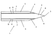
切削ブレード(1)は多層の切削ブレードであり、エッジ(3)を持つコア(2)と、それぞれがコアの面のうち一方を部分的に覆う2つの横腹(5)と、横腹(5)のどちらか一方とコア(2)の間にそれぞれが配置された2つの中間接続厚さ(4)とを備えている。 The cutting blade (1) is a multi-layer cutting blade, a core (2) having an edge (3), two flank (5) each partially covering one of the faces of the core, and a flank (5) And two intermediate connection thicknesses (4) each disposed between the core and the core (2).
それぞれの中間接続厚さ(4)は、コア(2)と接続する第1の接続面(8)および横腹(5)のどちらか一方と接続する第2の接続面(9)を有している。 Each intermediate connection thickness (4) has a first connection surface (8) connected to the core (2) and a second connection surface (9) connected to either the flank (5). Yes.
図1に示された実装例において、切削エッジ(3)は、好ましくは対称形の二重面の斜面(6)によって画定される。斜面(6)は横腹(5)へと延在しており、コア(2)と切削エッジ(3)のどちらかの側の横腹(5)の間に中間接続厚さ(4)を表している。横腹(5)のそれぞれは、斜めになった領域(6)まで延在する、非斜面式外面(7)を有している。変形例として、切削エッジ(3)を形成した後は、斜面(6)を切削ブレード(1)の唯一つの面上で間に合わせることもできる。 In the implementation example shown in FIG. 1, the cutting edge (3) is preferably defined by a symmetrical double-plane bevel (6). The slope (6) extends to the flank (5) and represents the intermediate connection thickness (4) between the flank (5) on either side of the core (2) and the cutting edge (3). Yes. Each of the flank (5) has a non-sloped outer surface (7) that extends to the beveled region (6). As a variant, after forming the cutting edge (3), the bevel (6) can be in time on only one face of the cutting blade (1).
切削エッジ(3)は、有利には、20°から50°の間の、好ましくは、25°から35°の間の先端角を有する。図1に示された実装例において、先端角は30°である。 The cutting edge (3) advantageously has a tip angle between 20 ° and 50 °, preferably between 25 ° and 35 °. In the mounting example shown in FIG. 1, the tip angle is 30 °.
図1に示された実装例において、各中間接続厚さ(4)は銅または銅合金の層によって形成されている。 In the implementation example shown in FIG. 1, each intermediate connection thickness (4) is formed by a layer of copper or copper alloy.
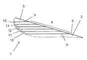
図2に示された実装例において、各中間切削厚さ(4)は多層構造で形成されており、該多層構造は、銅または銅合金の層で出来ている2つの外側層(10)、2つの外側層(10)の間に配置された、強靭な耐蝕性金属合金で出来ている2つの内側層(11)、および、銅または銅合金の層で出来ており、2つの内側層(11)の間に配置されるインタフェース層(12)を備えている。2つの外側層(10)は、第1の接続面(8)および第2の接続面を形成する。 In the implementation example shown in FIG. 2, each intermediate cutting thickness (4) is formed in a multilayer structure, the multilayer structure comprising two outer layers (10) made of copper or copper alloy layers, Two inner layers (11) made of a tough, corrosion-resistant metal alloy, and a layer of copper or copper alloy, placed between two outer layers (10), and two inner layers ( 11) with an interface layer (12) arranged between. The two outer layers (10) form a first connection surface (8) and a second connection surface.
したがって、中間切削厚さ(4)は、銅または銅合金の層により形成されて第1の接続面(8)および第2の接続面(9)を構成し、あるいは、一方では銅または銅合金の、および、他方では強靭な耐蝕性金属合金で出来ている内側層(11)の交互の層により形成されており、第1の接続面(8)および第2の接続面(9)は銅または銅合金で作られる。 Thus, the intermediate cutting thickness (4) is formed by a layer of copper or copper alloy to constitute the first connection surface (8) and the second connection surface (9), or on the one hand copper or copper alloy And, on the other hand, are formed by alternating layers of inner layers (11) made of a tough corrosion-resistant metal alloy, the first connection surface (8) and the second connection surface (9) being copper Or made of copper alloy.
コア(2)はマルテンサイト系のステンレススチールで出来ている。したがって、急冷後に強固な硬度、特に、52HRCよりも高い硬度または等しい硬度、および、好ましくは58HRCよりも高いまたは等しい硬度を獲得することが可能である。それでもやはり、切削エッジ(3)があまりにも壊れるのを防止するためには、62HRCよりも低い硬度または等しい硬度、好ましくは60HRCよりも低いまたは等しい硬度が望ましい。典型的に用いられるマルテンサイト系のステンレススチールのグレードは、例えば、X65Cr13,X105CrMoV15,X50CrMoV15,および,X40CrMoVN16−2である。 The core (2) is made of martensitic stainless steel. It is therefore possible to obtain a strong hardness after quenching, in particular a hardness higher than or equal to 52 HRC, and preferably a hardness higher than or equal to 58 HRC. Nevertheless, in order to prevent the cutting edge (3) from breaking too much, a hardness of less than or equal to 62 HRC, preferably less than or equal to 60 HRC is desirable. Typically used martensitic stainless steel grades are, for example, X65Cr13, X105CrMoV15, X50CrMoV15, and X40CrMoVN16-2.
一つの実装方法において、各中間接続厚さ(4)の第1の接続面(8)および第2の接続面(9)は、純銅、または、真鍮タイプの色合いを持つ90%Cu−10%Niの銅−ニッケルからなる。そのような色合いは、最大で10%のニッケルを含む銅−ニッケル合金に対して観察される。より高いニッケル成分の度合いが理由で、合金はその色合いを失い、したがって、その審美的な魅力を失う。それでもやはり、最大で25%のニッケルを含む銅−ニッケル合金が使用され得る。中間接続厚さ(4)において使用されるこれらの合金は、層間剥離なしで約1100℃まで、大変に良好な機械的強度をクラッドアセンブリにもたらし、このことが、マルテンサイト系ステンレススチールのコア(2)を強固にするために必要な急冷を実施することを可能にする。そのような実装方法は、特に、クラッディング(肉盛り)によって多層式切削ブレード(1)を製造することに対応する。 In one mounting method, the first connection surface (8) and the second connection surface (9) of each intermediate connection thickness (4) are 90% Cu-10% with a pure copper or brass type tint. It consists of nickel copper-nickel. Such a tint is observed for copper-nickel alloys containing up to 10% nickel. Because of the higher degree of nickel content, the alloy loses its color and thus loses its aesthetic appeal. Nevertheless, copper-nickel alloys containing up to 25% nickel can be used. These alloys used in the intermediate connection thickness (4) provide very good mechanical strength to the clad assembly up to about 1100 ° C. without delamination, which leads to the martensitic stainless steel core ( It makes it possible to carry out the rapid cooling necessary to strengthen 2). Such a mounting method corresponds in particular to the production of the multilayer cutting blade (1) by means of cladding.
別の実装方法において、多層式切削ブレード(1)を蝋付けによって製造し得る。各中間接続厚さ(4)の第1の接続面(8)および第2の接続面(9)を形成するために、高温蝋付けのための銀銅合金を用いることができる。 In another mounting method, the multilayer cutting blade (1) can be produced by brazing. A silver-copper alloy for high temperature brazing can be used to form the first connection surface (8) and the second connection surface (9) of each intermediate connection thickness (4).
横腹(5)は強靭な耐蝕性金属合金で出来ている。横腹(5)は、有利にはステンレススチールで、特にマルテンサイト系のステンレススチールで出来ている。好ましくは、X5CrNi18−10(SUS304)タイプのマルテンサイト系ステンレススチールが、切削ブレード(1)の非斜面式外面(7)の優れた耐蝕性を確実にするために使用される。そうは言うものの、他の材料、特にチタンまたはその合金、あるいは、フェライト系またはマルテンサイト系のステンレススチールを使用することもできる。また、横腹(5)用に多層構造を、特に異なる種類のステンレススチールの幾つもの異なる層の積層を、考慮に入れることもできる。 The flank (5) is made of a tough, corrosion-resistant metal alloy. The flank (5) is preferably made of stainless steel, in particular martensitic stainless steel. Preferably, X5CrNi18-10 (SUS304) type martensitic stainless steel is used to ensure excellent corrosion resistance of the non-sloped outer surface (7) of the cutting blade (1). Nevertheless, other materials, in particular titanium or its alloys, or ferritic or martensitic stainless steel can also be used. It is also possible to take into account a multilayer structure for the flank (5), in particular a stack of several different layers of different types of stainless steel.
所望するならば、横腹(5)は特にPVD(物理蒸着)式コーティングまたは電解型コーティングで被覆された非斜面式外面(7)を有していてよい。 If desired, the flank (5) may have a non-sloped outer surface (7) coated with a PVD (physical vapor deposition) coating or an electrolytic coating, among others.
コア(2)の厚さと多層式切削ブレード(1)の合計厚さの間の比率は1/3より大きいまたは1/3と等しく、好ましくは、0.5より大きいまたは0.5と等しい。したがって、コア(2)の厚さは切削ブレード(1)の厚さの1/3より大きいまたは1/3と等しく、好ましくは、切削ブレード(1)の厚さの半分より大きいまたは半分と等しい。実際、コア(2)のより薄い厚さのため、切削ブレード(1)を形成する多層材料の曲がり強度が低すぎ、屈曲後の永久的変形のリスクを伴う可能性がある。切削ブレード(1)のより良好な剛性のためには、コア(2)の厚さは、好ましくは、多層式切削ブレード(1)の合計厚さより大きいまたは合計厚さと等しい。コア(2)の厚さと多層式切削ブレード(1)の合計厚さの間の比率は、横腹(5)のためおよび中間接続厚さ(4)のために十分な厚さを有するためには、好ましくは0.8より小さい。 The ratio between the thickness of the core (2) and the total thickness of the multilayer cutting blade (1) is greater than or equal to 1/3, preferably greater than 0.5 or equal to 0.5. Thus, the thickness of the core (2) is greater than or equal to 1/3 of the thickness of the cutting blade (1), preferably greater than or equal to half the thickness of the cutting blade (1) . In fact, due to the thinner thickness of the core (2), the bending strength of the multilayer material forming the cutting blade (1) is too low, possibly with the risk of permanent deformation after bending. For better rigidity of the cutting blade (1), the thickness of the core (2) is preferably greater than or equal to the total thickness of the multilayer cutting blade (1). The ratio between the thickness of the core (2) and the total thickness of the multilayer cutting blade (1) is sufficient to have enough thickness for the flank (5) and for the intermediate connection thickness (4) , Preferably less than 0.8.
切削ブレード(1)は、好ましくは、1mmから8mmの間の合計厚さを有している。切削ブレード(1)の厚さは、横腹(5)の外面の間で画定される。コア(2)は、0.2から4mmの間の厚さを有している。各中間接続厚さ(4)は、50から250μmの間の厚さを有することができる。各横腹(5)は、0.2mmから2mmの間の厚さを有することができる。 The cutting blade (1) preferably has a total thickness between 1 mm and 8 mm. The thickness of the cutting blade (1) is defined between the outer surfaces of the flank (5). The core (2) has a thickness between 0.2 and 4 mm. Each intermediate connection thickness (4) can have a thickness between 50 and 250 μm. Each flank (5) can have a thickness between 0.2 mm and 2 mm.
多層式切削ブレード(1)を製造するための幾つかの異なる方法、特に、クラッディングまたは蝋付けによる方法が在る。 There are several different methods for producing the multilayer cutting blade (1), in particular by cladding or brazing.
クラッディングは、典型的には800℃から1100℃の間の高温で行われる。このクラッディング法の技術手法は、多層式切削ブレード(1)の異なる層の優れた接着を、特に熱処理の間に、達成することを可能にする。その主な問題は、コア(2)を形成しているマルテンサイト系のステンレススチールの治金特性:筋目の大きさの増大、二次炭化物の配分の変化などを修正しないことである。所望するならば、真空中でクラッディングを行ってもよい。 The cladding is typically performed at an elevated temperature between 800 ° C and 1100 ° C. This technical technique of the cladding method makes it possible to achieve excellent adhesion of the different layers of the multilayer cutting blade (1), in particular during heat treatment. The main problem is not to correct the metallurgical properties of the martensitic stainless steel forming the core (2): increase in the size of the streak, change in the distribution of secondary carbides, and the like. If desired, the cladding may be performed in a vacuum.
蝋付けは、中間接続厚さ(4)のために銀/銅合金における高温のブレイズを用いて行うことができる。 The brazing can be done using a high temperature blaze in the silver / copper alloy for the intermediate connection thickness (4).
切削ブレード(1)は、横腹(5)と中間接続厚さ(4)とコア(2)を備える多層構造を製作した後に、一般的にはレーザカッティングによって切り出される。 The cutting blade (1) is generally cut out by laser cutting after producing a multilayer structure comprising a flank (5), an intermediate connection thickness (4) and a core (2).
例えば440Cステンレススチールの場合、1010℃から1066℃の間の、油または空気による急冷が後に続く熱処理が行われ、150℃から250℃の間で一時間のテンパリングが後に続く。55HRCよりも大きいロックウェルC硬度が、こうして達成される。この熱処理は、満足のゆく強度およびパワーを、良好な耐衝撃性および耐蝕性と組み合わせて与える。多層式切削ブレード(1)の2つの側のうち少なくとも一方を機械加工することからなる研削が実施され、切削エッジ(3)を形成する尖ったリッジを作るために斜面(6)が作られる。 For example, in the case of 440C stainless steel, heat treatment between 1010 ° C. and 1066 ° C. followed by quenching with oil or air is performed, followed by temporary tempering between 150 ° C. and 250 ° C. A Rockwell C hardness greater than 55 HRC is thus achieved. This heat treatment provides satisfactory strength and power in combination with good impact and corrosion resistance. Grinding consisting of machining at least one of the two sides of the multi-layer cutting blade (1) is performed, and a bevel (6) is created to create a sharp ridge that forms the cutting edge (3).
切削性能の測定は、切削ブレードの切削強度を定量化するキャラクタリゼーションに基づいて行われる。そのような試験は、標準EN ISO 8442−5に記載されている。この標準は、切削ブレードのICP(初期の切削性能:initial cutting performance)およびTCC(合計のカードカット:total card cut)をどのようにして測定するかについて記載している。上で説明した処理は、初期の切削性能を劣化させることなくTCCパラメータを著しく改善する。同じ様にして、ブレードの耐蝕性は、標準EN ISO 8442−1における記載にしたがって検証される。耐蝕性試験を使用して、304ステンレススチールの耐蝕性が影響を受けなかったことを検証した。 The measurement of the cutting performance is performed based on a characterization that quantifies the cutting strength of the cutting blade. Such a test is described in the standard EN ISO 8442-5. This standard describes how to measure ICP (initial cutting performance) and TCC (total card cut) of a cutting blade. The process described above significantly improves the TCC parameters without degrading the initial cutting performance. In the same way, the corrosion resistance of the blade is verified as described in the standard EN ISO 8442-1. A corrosion resistance test was used to verify that the corrosion resistance of 304 stainless steel was not affected.
変形例として、中間接続厚さ(4)のうち少なくとも1つを、銅または銅合金の層によって形成することができる。 As a variant, at least one of the intermediate connection thicknesses (4) can be formed by a layer of copper or copper alloy.
変形例として、中間接続厚さ(4)の少なくとも1つを多層構造で形成することができ、その多層構造は、銅または銅合金の層で出来ている2つの外側層(10)と、強靭な耐蝕性金属合金で出来ており、2つの外側層(10)の間に配置される少なくとも1つの内側層(11)と、銅または銅合金の層で出来ており、そうして、中間接続厚さ(4)がいくつもの内側層(11)を有している場合に、隣り合う2つの内側層(11)の間に配置されるインタフェース層(12)とを備えている。したがって、各内側層(11)は、2つの外側層(10)の間に、あるいは、1つの外側層(10)と1つのインタフェース層(12)の間または2つのインタフェース層(12)の間に配置される。 As a variant, at least one of the intermediate connection thicknesses (4) can be formed in a multilayer structure, the multilayer structure comprising two outer layers (10) made of copper or a copper alloy layer and a toughness. Made of a special corrosion-resistant metal alloy, made of at least one inner layer (11) arranged between two outer layers (10) and a layer of copper or copper alloy, so that an intermediate connection When the thickness (4) has a number of inner layers (11), an interface layer (12) is provided between two adjacent inner layers (11). Thus, each inner layer (11) is between two outer layers (10) or between one outer layer (10) and one interface layer (12) or between two interface layers (12). Placed in.
本発明はまた、多層式切削ブレード(1)を製造するための方法であって、以下のステップを含む方法に関する。 The invention also relates to a method for manufacturing a multi-layer cutting blade (1) comprising the following steps.
多層シートの作成または供給であって、その多層シートが、
−マルテンサイト系のステンレススチールで出来ているコア(2)であって、その厚さが多層構造の厚さの1/3より大きいまたは1/3と等しい、コア、
−強靭な耐蝕性金属合金で出来ている2つの横腹(5)、
−横腹(5)のどちらか一方とコア(2)の間においてそれぞれが配置された2つの中間接続厚さ(4)であって、各中間接続厚さ(4)が銅または銅合金で出来ているか、または、銅または銅合金のいずれかで出来ている別の層または強靭な耐蝕性金属合金を有しており、そのために、コアまたは横腹の一方に隣接する、中間接続厚さ(4)の各層が銅または銅合金で出来ている、2つの中間接続厚さを含んでいる、多層シートの作成または供給。
Creation or supply of a multilayer sheet, the multilayer sheet being
A core (2) made of martensitic stainless steel, the thickness of which is greater than or equal to 1/3 of the thickness of the multilayer structure;
-Two flank (5) made of a tough, corrosion-resistant metal alloy,
-Two intermediate connection thicknesses (4) each arranged between one of the flank (5) and the core (2), each intermediate connection thickness (4) made of copper or copper alloy Or having another layer made of either copper or copper alloy or a tough, corrosion-resistant metal alloy, so that an intermediate connection thickness (4 adjacent to one of the core or flank) The production or supply of a multi-layer sheet comprising two intermediate connection thicknesses, each layer of copper or copper alloy.
切削ブレード(1)の形状を多層シートから切り出すこと。 Cutting the shape of the cutting blade (1) from the multilayer sheet.
1000℃から1100℃の間の温度での切削ブレード(1)の形状の熱処理であって、油または空気による急冷が後に続く、熱処理。 A heat treatment of the shape of the cutting blade (1) at a temperature between 1000 ° C. and 1100 ° C. followed by quenching with oil or air.
200℃から400℃の間の温度での切削ブレード(1)の形状のテンパリング処理。 Tempering of the shape of the cutting blade (1) at a temperature between 200 ° C and 400 ° C.
切削ブレード(1)の形状の1つのエッジの少なくとも1つの部分の面取りであって、切削エッジ(3)をコア(2)内に形成するための面取り。 Chamfering of at least one part of one edge of the shape of the cutting blade (1) for forming the cutting edge (3) in the core (2).
一つの実装方法において、プロセスが、クラッディングによって組み立てられた多層シートを作ることまたは使用することからなり、銅または銅合金で出来ている中間接続厚さ(4)の層は、純銅または最大で25%のニッケルを含む銅−ニッケル合金から構成され、好ましくは、銅−ニッケル合金は最大で10%のニッケルを含む。 In one mounting method, the process consists of making or using a multilayer sheet assembled by cladding, and the layer of intermediate connection thickness (4) made of copper or copper alloy is pure copper or at most Consists of a copper-nickel alloy containing 25% nickel, preferably the copper-nickel alloy contains up to 10% nickel.
一つの実装方法において、プロセスが、蝋付けによって組み立てられた多層シートを作ることまたは使用することからなり、銅合金で出来ている中間接続厚さ(4)の層は、高温蝋付けのための銅−銀合金から構成される。 In one mounting method, the process consists of making or using a multilayer sheet assembled by brazing, and the intermediate connection thickness (4) layer made of copper alloy is used for high temperature brazing. It is composed of a copper-silver alloy.
本発明は説明した実装例およびそれらの変形に決して限定されず、しかし、請求の範囲の範囲内で多くの修正を包含する。 The present invention is in no way limited to the implementations described and variations thereof, but includes many modifications within the scope of the claims.
Claims (22)
前記コア(2)がマルテンサイト系のステンレススチールで出来ていること、および、前記コア(2)の厚さが本切削ブレード(1)の厚さの1/3より大きいまたは1/3と等しいことを特徴とする多層式切削ブレード(1)。 A multi-layer cutting blade (1) having a core (2) having an edge (3), two flank (5) each partially covering one of the surfaces of the core (2), and the flank (5) and an intermediate connection thickness (4) each disposed between the core (2), and the flank (5) is made of a tough corrosion-resistant metal alloy, The intermediate connection thickness (4) has a first connection surface (8) connected to the core (2) and a second connection surface (9) connected to either the flank (5), In the multilayer cutting blade (1), wherein the first connection surface (8) and the second connection surface (9) are made of copper or a copper alloy,
The core (2) is made of martensitic stainless steel, and the thickness of the core (2) is greater than or equal to 1/3 of the thickness of the cutting blade (1). A multilayer cutting blade (1) characterized by the above.
−多層シートの作成または供給であって、該多層シートが、
−マルテンサイト系のステンレススチールで出来ているコア(2)であって、その厚さが多層構造の厚さの1/3より大きいまたは1/3と等しい、コア(2)、
− 強靭な耐蝕性金属合金で出来ている2つの横腹(5)、
− 前記横腹(5)のどちらか一方と前記コア(2)の間にそれぞれが配置された2つの中間接続厚さ(4)であって、各中間接続厚さ(4)が銅または銅合金で出来ているか、または、銅または銅合金のいずれかで出来ているかまたは強靭な耐蝕性金属合金で出来ている交互の層を有しており、そのために、前記コア(2)または前記横腹(5)の一方に隣接する、前記中間接続厚さ(4)の各層が銅または銅合金で出来ている、2つの中間接続厚さ(4)を含んでいる、多層シートの作成または供給、
−切削ブレード(1)の形状を前記多層シートから切り出すこと、
−1000℃から1100℃の間の温度での前記切削ブレード(1)の形状の熱処理であって、油または空気による急冷が後に続く、熱処理、
−200℃から400℃の間の温度での前記切削ブレード(1)の形状のテンパリング処理、並びに、
−前記切削ブレード(1)の形状の1つのエッジの少なくとも1つの部分の面取りであって、切削エッジ(3)を前記コア(2)内に形成するための面取り
を含むことを特徴とする、多層式切削ブレード(1)を製造するための方法。 A method for producing a multi-layer cutting blade (1) comprising the following steps:
-Creation or supply of a multilayer sheet, wherein the multilayer sheet comprises:
A core (2) made of martensitic stainless steel, the thickness of which is greater than or equal to 1/3 of the thickness of the multilayer structure, core (2),
-Two flank (5) made of a tough, corrosion-resistant metal alloy,
-Two intermediate connection thicknesses (4) each disposed between one of the flank (5) and the core (2), each intermediate connection thickness (4) being copper or copper alloy Or have alternating layers made of either copper or copper alloy or made of a tough, corrosion-resistant metal alloy, so that the core (2) or the flank ( 5) making or supplying a multilayer sheet comprising two intermediate connection thicknesses (4), each layer of said intermediate connection thickness (4) being made of copper or a copper alloy, adjacent to one of 5)
-Cutting the shape of the cutting blade (1) from the multilayer sheet;
A heat treatment of the shape of said cutting blade (1) at a temperature between -1000 ° C. and 1100 ° C., followed by quenching with oil or air,
A tempering treatment of the shape of the cutting blade (1) at a temperature between −200 ° C. and 400 ° C., and
-Chamfering of at least one part of one edge of the shape of the cutting blade (1), comprising chamfering for forming a cutting edge (3) in the core (2), A method for producing a multilayer cutting blade (1).
Applications Claiming Priority (3)
| Application Number | Priority Date | Filing Date | Title |
|---|---|---|---|
| FR1363312 | 2013-12-20 | ||
| FR1363312A FR3015336B1 (en) | 2013-12-20 | 2013-12-20 | MULTILAYER CUTTING BLADE COMPRISING A STAINLESS STEEL HEART |
| PCT/FR2014/053434 WO2015092304A1 (en) | 2013-12-20 | 2014-12-18 | Multilayer cutting blade having a stainless steel core |
Publications (2)
| Publication Number | Publication Date |
|---|---|
| JP2017502847A true JP2017502847A (en) | 2017-01-26 |
| JP2017502847A5 JP2017502847A5 (en) | 2018-02-01 |
Family
ID=50290025
Family Applications (1)
| Application Number | Title | Priority Date | Filing Date |
|---|---|---|---|
| JP2016540976A Pending JP2017502847A (en) | 2013-12-20 | 2014-12-18 | Multi-layer cutting blade with stainless steel core |
Country Status (8)
| Country | Link |
|---|---|
| US (1) | US20160333436A1 (en) |
| EP (1) | EP3083240A1 (en) |
| JP (1) | JP2017502847A (en) |
| KR (1) | KR20160102222A (en) |
| CN (1) | CN105899355A (en) |
| CA (1) | CA2934057A1 (en) |
| FR (1) | FR3015336B1 (en) |
| WO (1) | WO2015092304A1 (en) |
Families Citing this family (3)
| Publication number | Priority date | Publication date | Assignee | Title |
|---|---|---|---|---|
| CN111331963B (en) * | 2020-03-27 | 2024-01-05 | 嘉兴吉森科技有限公司 | Multilayer composite steel and manufacturing method of multilayer composite steel cutter |
| CN111531239A (en) * | 2020-04-30 | 2020-08-14 | 重庆派斯克刀具制造股份有限公司 | High-frequency brazing and heat treatment process for planing tool |
| KR102223936B1 (en) * | 2020-06-11 | 2021-03-05 | 전미숙 | Knife and manufacturing method of the knife |
Citations (8)
| Publication number | Priority date | Publication date | Assignee | Title |
|---|---|---|---|---|
| JPS51146340A (en) * | 1975-06-12 | 1976-12-15 | Rejin Seiki Kougiyou Kk | Satining method |
| JPH0191477U (en) * | 1987-12-03 | 1989-06-15 | ||
| US5256496A (en) * | 1991-11-15 | 1993-10-26 | Kluczynski Mathew L | Titanium-steel laminate knife |
| JPH1176642A (en) * | 1997-08-29 | 1999-03-23 | Aichi Steel Works Ltd | Antimicrobial clad cutting tool |
| JP2003340591A (en) * | 2002-05-28 | 2003-12-02 | Kyocera Corp | Structure for joining metallic member each other |
| JP2008259598A (en) * | 2007-04-11 | 2008-10-30 | Sri Sports Ltd | Golf club head |
| JP2011212226A (en) * | 2010-03-31 | 2011-10-27 | Nisshin Steel Co Ltd | Cutter, cutter material excellent in antibacterial property, and method of manufacturing the same |
| JP2013061056A (en) * | 2011-09-15 | 2013-04-04 | Nissan Motor Co Ltd | Gas seal member, fuel cell and method for manufacturing fuel cell |
Family Cites Families (17)
| Publication number | Priority date | Publication date | Assignee | Title |
|---|---|---|---|---|
| US1926961A (en) * | 1931-11-27 | 1933-09-12 | Sharples Solvents Corp | Composition and method for the relative freeing and lubricating of engaging surfaces |
| US2713902A (en) * | 1950-04-18 | 1955-07-26 | Biss Robert | Steel cutting rule |
| US3537828A (en) * | 1967-02-13 | 1970-11-03 | United States Steel Corp | Composite stainless steel article |
| US3488844A (en) * | 1967-07-28 | 1970-01-13 | Ed Lesh | Edged laminated cutting tool |
| JPS5987988A (en) * | 1982-11-13 | 1984-05-21 | Daihou Giken Kk | Composite stainless steel for blade |
| DE3339904A1 (en) * | 1983-11-04 | 1985-05-15 | Bergische Stahl-Industrie | THREE-LAYER STEEL AND ITS USE FOR CUTTER KNIVES ETC. |
| SE450495B (en) * | 1984-10-12 | 1987-06-29 | Swedev Ab | Laminated tool steel material |
| US4770067A (en) * | 1987-06-08 | 1988-09-13 | Kollmorgen Corporation | Method of manufacturing surgical cutting tools for thermally aided surgery |
| JP2732206B2 (en) * | 1993-09-13 | 1998-03-25 | 日本金属工業株式会社 | Manufacturing method of clad material for blades |
| US5718615A (en) * | 1995-10-20 | 1998-02-17 | Boucher; John N. | Semiconductor wafer dicing method |
| US7712222B2 (en) * | 2001-07-26 | 2010-05-11 | Irwin Industrial Tool Company | Composite utility blade, and method of making such a blade |
| CN201055998Y (en) * | 2007-06-21 | 2008-05-07 | 黄维明 | Antimicrobial kitchen knife |
| KR20090085943A (en) * | 2008-02-05 | 2009-08-10 | 아키코 히라이 | Method of manufacturing a knife with high hardness nitride layer |
| JP5639153B2 (en) * | 2009-04-29 | 2014-12-10 | ナムローゼ・フェンノートシャップ・ベーカート・ソシエテ・アノニムN V Bekaert Societe Anonyme | A saw wire in which abrasive grains are partially embedded in a metal wire and partially held by an organic binder |
| US20130259698A1 (en) * | 2012-03-28 | 2013-10-03 | General Electric Company | Method of Joining at Least Two Components, a Method for Rendering a Component Resistant to Eroision, and a Turbine Blade |
| DE102012106351B4 (en) * | 2012-07-13 | 2015-11-19 | C. & E. Fein Gmbh | Saw blade or cut-off blade made of martensitic stainless steel or steel and process for its production |
| DE102013112632A1 (en) * | 2013-11-15 | 2015-05-21 | C. & E. Fein Gmbh | Saw blade for an oscillating driven saw |
-
2013
- 2013-12-20 FR FR1363312A patent/FR3015336B1/en not_active Expired - Fee Related
-
2014
- 2014-12-18 CN CN201480073017.8A patent/CN105899355A/en active Pending
- 2014-12-18 KR KR1020167019133A patent/KR20160102222A/en not_active Application Discontinuation
- 2014-12-18 EP EP14830984.2A patent/EP3083240A1/en not_active Withdrawn
- 2014-12-18 US US15/106,629 patent/US20160333436A1/en not_active Abandoned
- 2014-12-18 CA CA2934057A patent/CA2934057A1/en not_active Abandoned
- 2014-12-18 WO PCT/FR2014/053434 patent/WO2015092304A1/en active Application Filing
- 2014-12-18 JP JP2016540976A patent/JP2017502847A/en active Pending
Patent Citations (8)
| Publication number | Priority date | Publication date | Assignee | Title |
|---|---|---|---|---|
| JPS51146340A (en) * | 1975-06-12 | 1976-12-15 | Rejin Seiki Kougiyou Kk | Satining method |
| JPH0191477U (en) * | 1987-12-03 | 1989-06-15 | ||
| US5256496A (en) * | 1991-11-15 | 1993-10-26 | Kluczynski Mathew L | Titanium-steel laminate knife |
| JPH1176642A (en) * | 1997-08-29 | 1999-03-23 | Aichi Steel Works Ltd | Antimicrobial clad cutting tool |
| JP2003340591A (en) * | 2002-05-28 | 2003-12-02 | Kyocera Corp | Structure for joining metallic member each other |
| JP2008259598A (en) * | 2007-04-11 | 2008-10-30 | Sri Sports Ltd | Golf club head |
| JP2011212226A (en) * | 2010-03-31 | 2011-10-27 | Nisshin Steel Co Ltd | Cutter, cutter material excellent in antibacterial property, and method of manufacturing the same |
| JP2013061056A (en) * | 2011-09-15 | 2013-04-04 | Nissan Motor Co Ltd | Gas seal member, fuel cell and method for manufacturing fuel cell |
Also Published As
| Publication number | Publication date |
|---|---|
| US20160333436A1 (en) | 2016-11-17 |
| CN105899355A (en) | 2016-08-24 |
| FR3015336A1 (en) | 2015-06-26 |
| EP3083240A1 (en) | 2016-10-26 |
| CA2934057A1 (en) | 2015-06-25 |
| KR20160102222A (en) | 2016-08-29 |
| WO2015092304A1 (en) | 2015-06-25 |
| FR3015336B1 (en) | 2016-02-05 |
Similar Documents
| Publication | Publication Date | Title |
|---|---|---|
| US8471168B2 (en) | Methods of treating metal articles and articles made therefrom | |
| JP6194437B2 (en) | Knife | |
| CN106457411B (en) | Cutting element | |
| JP2017502847A (en) | Multi-layer cutting blade with stainless steel core | |
| JP2010000540A5 (en) | ||
| ES2300070T5 (en) | Blade with an overlapping forged blade bend | |
| EP3476525A1 (en) | Method for manufacturing ultra-hard and wear-resistant composite blade | |
| JP2018533420A (en) | Razor blade | |
| CN101657303A (en) | Cutting eleemnt, electric shaver provided with a cutting element and method for producing such element | |
| JP5782497B2 (en) | Manufacturing method for drilling tools | |
| JP2013176778A (en) | Laser cladding method and tool material | |
| CN107614168A (en) | Cutting element | |
| CN115094413A (en) | High-end pure titanium cutter based on laser cladding titanium alloy powder and preparation method thereof | |
| CN212796114U (en) | Multilayer composite steel | |
| CN111331963B (en) | Multilayer composite steel and manufacturing method of multilayer composite steel cutter | |
| JP2017502847A5 (en) | ||
| CN208592870U (en) | Cutter | |
| CN109274231A (en) | A kind of processing technology with titanium production motor case | |
| CN111148458B (en) | Cookware with copper bonding layer | |
| WO2018216641A1 (en) | Cutting tool material, method for manufacturing cutting tool material, and cutting tool | |
| JP2011212226A (en) | Cutter, cutter material excellent in antibacterial property, and method of manufacturing the same | |
| EP3931362B1 (en) | Razor blade and composition for a razor blade | |
| JP2010280050A (en) | Cutter, method of manufacturing the same, and slicing device | |
| CN110066994A (en) | The processing method of cutter and the cutter | |
| CN113637968A (en) | Self-sharpening cutting edge and manufacturing method thereof |
Legal Events
| Date | Code | Title | Description |
|---|---|---|---|
| A521 | Request for written amendment filed |
Free format text: JAPANESE INTERMEDIATE CODE: A523 Effective date: 20171215 |
|
| A621 | Written request for application examination |
Free format text: JAPANESE INTERMEDIATE CODE: A621 Effective date: 20171215 |
|
| A977 | Report on retrieval |
Free format text: JAPANESE INTERMEDIATE CODE: A971007 Effective date: 20180906 |
|
| A131 | Notification of reasons for refusal |
Free format text: JAPANESE INTERMEDIATE CODE: A131 Effective date: 20180911 |
|
| A521 | Request for written amendment filed |
Free format text: JAPANESE INTERMEDIATE CODE: A523 Effective date: 20181205 |
|
| A02 | Decision of refusal |
Free format text: JAPANESE INTERMEDIATE CODE: A02 Effective date: 20190604 |