JP2017501801A - Drug delivery device assembly and drug delivery device - Google Patents
Drug delivery device assembly and drug delivery device Download PDFInfo
- Publication number
- JP2017501801A JP2017501801A JP2016541261A JP2016541261A JP2017501801A JP 2017501801 A JP2017501801 A JP 2017501801A JP 2016541261 A JP2016541261 A JP 2016541261A JP 2016541261 A JP2016541261 A JP 2016541261A JP 2017501801 A JP2017501801 A JP 2017501801A
- Authority
- JP
- Japan
- Prior art keywords
- assembly
- interaction
- dose
- delivery
- during
- Prior art date
- Legal status (The legal status is an assumption and is not a legal conclusion. Google has not performed a legal analysis and makes no representation as to the accuracy of the status listed.)
- Abandoned
Links
Images
Classifications
-
- A—HUMAN NECESSITIES
- A61—MEDICAL OR VETERINARY SCIENCE; HYGIENE
- A61M—DEVICES FOR INTRODUCING MEDIA INTO, OR ONTO, THE BODY; DEVICES FOR TRANSDUCING BODY MEDIA OR FOR TAKING MEDIA FROM THE BODY; DEVICES FOR PRODUCING OR ENDING SLEEP OR STUPOR
- A61M5/00—Devices for bringing media into the body in a subcutaneous, intra-vascular or intramuscular way; Accessories therefor, e.g. filling or cleaning devices, arm-rests
- A61M5/178—Syringes
- A61M5/31—Details
- A61M5/315—Pistons; Piston-rods; Guiding, blocking or restricting the movement of the rod or piston; Appliances on the rod for facilitating dosing ; Dosing mechanisms
- A61M5/31565—Administration mechanisms, i.e. constructional features, modes of administering a dose
- A61M5/31576—Constructional features or modes of drive mechanisms for piston rods
- A61M5/31583—Constructional features or modes of drive mechanisms for piston rods based on rotational translation, i.e. movement of piston rod is caused by relative rotation between the user activated actuator and the piston rod
- A61M5/31585—Constructional features or modes of drive mechanisms for piston rods based on rotational translation, i.e. movement of piston rod is caused by relative rotation between the user activated actuator and the piston rod performed by axially moving actuator, e.g. an injection button
-
- A—HUMAN NECESSITIES
- A61—MEDICAL OR VETERINARY SCIENCE; HYGIENE
- A61M—DEVICES FOR INTRODUCING MEDIA INTO, OR ONTO, THE BODY; DEVICES FOR TRANSDUCING BODY MEDIA OR FOR TAKING MEDIA FROM THE BODY; DEVICES FOR PRODUCING OR ENDING SLEEP OR STUPOR
- A61M5/00—Devices for bringing media into the body in a subcutaneous, intra-vascular or intramuscular way; Accessories therefor, e.g. filling or cleaning devices, arm-rests
- A61M5/178—Syringes
- A61M5/20—Automatic syringes, e.g. with automatically actuated piston rod, with automatic needle injection, filling automatically
- A61M5/2033—Spring-loaded one-shot injectors with or without automatic needle insertion
-
- A—HUMAN NECESSITIES
- A61—MEDICAL OR VETERINARY SCIENCE; HYGIENE
- A61M—DEVICES FOR INTRODUCING MEDIA INTO, OR ONTO, THE BODY; DEVICES FOR TRANSDUCING BODY MEDIA OR FOR TAKING MEDIA FROM THE BODY; DEVICES FOR PRODUCING OR ENDING SLEEP OR STUPOR
- A61M5/00—Devices for bringing media into the body in a subcutaneous, intra-vascular or intramuscular way; Accessories therefor, e.g. filling or cleaning devices, arm-rests
- A61M5/178—Syringes
- A61M5/24—Ampoule syringes, i.e. syringes with needle for use in combination with replaceable ampoules or carpules, e.g. automatic
-
- A—HUMAN NECESSITIES
- A61—MEDICAL OR VETERINARY SCIENCE; HYGIENE
- A61M—DEVICES FOR INTRODUCING MEDIA INTO, OR ONTO, THE BODY; DEVICES FOR TRANSDUCING BODY MEDIA OR FOR TAKING MEDIA FROM THE BODY; DEVICES FOR PRODUCING OR ENDING SLEEP OR STUPOR
- A61M5/00—Devices for bringing media into the body in a subcutaneous, intra-vascular or intramuscular way; Accessories therefor, e.g. filling or cleaning devices, arm-rests
- A61M5/178—Syringes
- A61M5/31—Details
- A61M5/315—Pistons; Piston-rods; Guiding, blocking or restricting the movement of the rod or piston; Appliances on the rod for facilitating dosing ; Dosing mechanisms
- A61M5/31533—Dosing mechanisms, i.e. setting a dose
- A61M5/31545—Setting modes for dosing
- A61M5/31548—Mechanically operated dose setting member
- A61M5/3155—Mechanically operated dose setting member by rotational movement of dose setting member, e.g. during setting or filling of a syringe
- A61M5/31553—Mechanically operated dose setting member by rotational movement of dose setting member, e.g. during setting or filling of a syringe without axial movement of dose setting member
-
- A—HUMAN NECESSITIES
- A61—MEDICAL OR VETERINARY SCIENCE; HYGIENE
- A61M—DEVICES FOR INTRODUCING MEDIA INTO, OR ONTO, THE BODY; DEVICES FOR TRANSDUCING BODY MEDIA OR FOR TAKING MEDIA FROM THE BODY; DEVICES FOR PRODUCING OR ENDING SLEEP OR STUPOR
- A61M5/00—Devices for bringing media into the body in a subcutaneous, intra-vascular or intramuscular way; Accessories therefor, e.g. filling or cleaning devices, arm-rests
- A61M5/178—Syringes
- A61M5/31—Details
- A61M5/315—Pistons; Piston-rods; Guiding, blocking or restricting the movement of the rod or piston; Appliances on the rod for facilitating dosing ; Dosing mechanisms
- A61M5/31565—Administration mechanisms, i.e. constructional features, modes of administering a dose
- A61M5/31576—Constructional features or modes of drive mechanisms for piston rods
- A61M5/31583—Constructional features or modes of drive mechanisms for piston rods based on rotational translation, i.e. movement of piston rod is caused by relative rotation between the user activated actuator and the piston rod
-
- A—HUMAN NECESSITIES
- A61—MEDICAL OR VETERINARY SCIENCE; HYGIENE
- A61M—DEVICES FOR INTRODUCING MEDIA INTO, OR ONTO, THE BODY; DEVICES FOR TRANSDUCING BODY MEDIA OR FOR TAKING MEDIA FROM THE BODY; DEVICES FOR PRODUCING OR ENDING SLEEP OR STUPOR
- A61M5/00—Devices for bringing media into the body in a subcutaneous, intra-vascular or intramuscular way; Accessories therefor, e.g. filling or cleaning devices, arm-rests
- A61M5/178—Syringes
- A61M5/20—Automatic syringes, e.g. with automatically actuated piston rod, with automatic needle injection, filling automatically
- A61M2005/2086—Automatic syringes, e.g. with automatically actuated piston rod, with automatic needle injection, filling automatically having piston damping means, e.g. axially or rotationally acting retarders
-
- A—HUMAN NECESSITIES
- A61—MEDICAL OR VETERINARY SCIENCE; HYGIENE
- A61M—DEVICES FOR INTRODUCING MEDIA INTO, OR ONTO, THE BODY; DEVICES FOR TRANSDUCING BODY MEDIA OR FOR TAKING MEDIA FROM THE BODY; DEVICES FOR PRODUCING OR ENDING SLEEP OR STUPOR
- A61M5/00—Devices for bringing media into the body in a subcutaneous, intra-vascular or intramuscular way; Accessories therefor, e.g. filling or cleaning devices, arm-rests
- A61M5/48—Devices for bringing media into the body in a subcutaneous, intra-vascular or intramuscular way; Accessories therefor, e.g. filling or cleaning devices, arm-rests having means for varying, regulating, indicating or limiting injection pressure
- A61M5/482—Varying injection pressure, e.g. by varying speed of injection
Abstract
薬物送達デバイス用アセンブリ、および薬物送達デバイス。薬物送達デバイス(1)用アセンブリであって、アセンブリの用量送達動作をトリガするように、送達方向へと軸方向に動くように適用され、配置された起動部材(6A)と、アセンブリの用量送達動作中、機械的に互いに協働し、かつ用量送達動作中、互いに回転するように適用され、配置された第1の相互作用部材(17)、および第2の相互作用部材(18)とを含み、ここで、アセンブリは、起動部材(6A)が送達方向に動くことによって、相互作用部材(17、18)が機械的に接触して相互作用部材(17、18)間で摩擦が生じるように構成され、ここで、摩擦の量によって、用量送達動作中の相互作用部材(17、18)の相対回転速度を制御する、薬物送達デバイス用アセンブリが記載されている。さらに、このアセンブリを含む薬物送達デバイスが記載されている。An assembly for a drug delivery device and a drug delivery device. An assembly for a drug delivery device (1), wherein the actuating member (6A) is adapted and arranged to move axially in the delivery direction to trigger a dose delivery operation of the assembly, and dose delivery of the assembly A first interaction member (17) and a second interaction member (18) applied and arranged to mechanically cooperate with each other during operation and to rotate with each other during dose delivery operation; Wherein the assembly is such that the actuation member (6A) moves in the delivery direction such that the interaction members (17, 18) are in mechanical contact and friction between the interaction members (17, 18) occurs. Wherein the assembly for a drug delivery device is described wherein the relative rotational speed of the interaction member (17, 18) during dose delivery operation is controlled by the amount of friction. In addition, a drug delivery device including this assembly is described.
Description
本開示は、薬物送達デバイス用アセンブリに関する。本開示は、さらに薬物送達デバイスに関する。特に、本開示は、ペン型薬物送達デバイスに関する。 The present disclosure relates to an assembly for a drug delivery device. The present disclosure further relates to a drug delivery device. In particular, the present disclosure relates to pen-type drug delivery devices.
ペン型薬物送達デバイスが、正式な医療訓練を受けていない人々による注射に使用されている。こうした注射は、糖尿病などの患者の間で自己治療として広く使用されてきている。駆動機構によってカートリッジ内の栓(bung)が変位し、カートリッジ内に収容された薬物が針から投薬されることになる。 Pen-type drug delivery devices are used for injection by people who do not have formal medical training. Such injections have been widely used as self-treatment among patients such as diabetes. The bung in the cartridge is displaced by the driving mechanism, and the drug contained in the cartridge is dispensed from the needle.
注射前に、必要用量の薬物が、用量設定機構によって設定(set)される。用量設定機構の通常の設計では、用量設定スリーブ、用量指示スリーブ、駆動スリーブ、および/またはラチェットスリーブなどの、いくつかの管状またはスリーブ状の要素が含まれる。そのようなスリーブは、互いに入れ子になり(accommodate)、連結されていることが多い。デバイスによっては、動力補助(power assist)、特に、エネルギー蓄積部材(energy storing member)を含み、ここで、用量設定中、エネルギーをエネルギー蓄積部材に蓄積しておくことができる。このエネルギーは、用量送達中に解放することができる。 Prior to injection, the required dose of drug is set by a dose setting mechanism. Typical designs for dose setting mechanisms include several tubular or sleeve-like elements such as dose setting sleeves, dose indicating sleeves, drive sleeves, and / or ratchet sleeves. Such sleeves are often nested and connected to each other. Some devices include a power assist, in particular an energy storing member, where energy can be stored in the energy storing member during dose setting. This energy can be released during dose delivery.
動力補助付き薬物送達デバイスが、たとえば特許文献1に記載されている。 A power-assisted drug delivery device is described, for example, in US Pat.
動力補助付き薬物送達デバイスは、特に、より多くの容量を注射しようとする場合、かつ/または粘度の高い流体を注射しようとする場合に有益となる。エネルギー蓄積部材は、全用量を送達することが可能となるように十分な力プロファイル(force profile)を有しなければならない。このため、少なくとも少量の用量が、高い力で、したがって高速で投薬されるという影響がもたらされる。高速の注射によって、注射される組織が応力を受けるので、使用者が不快に感じることがあり、使用者が痛みを感じることすらある。 Power assisted drug delivery devices are particularly beneficial when trying to inject more volume and / or when trying to inject a viscous fluid. The energy storage member must have a sufficient force profile to be able to deliver the entire dose. This has the effect that at least small doses are dosed with high force and therefore at high speed. Fast injection can stress the tissue being injected, which can cause the user to feel uncomfortable and can even cause the user to feel pain.
本開示の目的は、改善された特性を有する、たとえば、使用者の使い心地が増した薬物送達デバイスを提供することである。 An object of the present disclosure is to provide a drug delivery device having improved properties, for example, increased user comfort.
この目的は、独立請求項の主題によって達成することができる。有利な実施形態、および改良形態は、従属請求項の主題である。 This object can be achieved by the subject matter of the independent claims. Advantageous embodiments and refinements are the subject of the dependent claims.
一態様は、薬物送達デバイス用アセンブリに関する。このアセンブリは、デバイスの駆動機構を含むことができる。駆動機構とは、デバイスからの薬物の用量を設定し、かつ/または投薬するように適用された機構でよい。このアセンブリは、起動部材を含むことができる。起動部材は、アセンブリの用量送達動作をトリガするように、送達方向に動くように適用させ、配置することができる。起動部材は、送達方向へと軸方向に可動(movable)とすることができる。起動部材は、送達方向に動くとき、回転または傾斜するのを防止することができる。起動部材は、アセンブリの、したがって薬物の用量を送達するためのデバイスの主長手方向軸(main longitudinal axis)に対して半径方向に動くのを防止することができる。起動部材を少なくとも部分的に送達方向に動かすことによって、用量送達動作を開始することができる。起動部材は、たとえば用量ボタンを含むことができる。 One aspect relates to an assembly for a drug delivery device. The assembly can include a drive mechanism for the device. The drive mechanism may be a mechanism adapted to set and / or dispense a drug dose from the device. The assembly can include an activation member. The activation member can be applied and positioned to move in the delivery direction to trigger a dose delivery operation of the assembly. The activation member can be movable axially in the delivery direction. The activation member may prevent rotation or tilting when moving in the delivery direction. The activation member can prevent radial movement relative to the main longitudinal axis of the assembly and thus the device for delivering a dose of drug. The dose delivery operation can be initiated by moving the activation member at least partially in the delivery direction. The activation member can include, for example, a dose button.
このアセンブリは、第1の相互作用部材(interaction member)をさらに含むことができる。このアセンブリは、第2の相互作用部材を含むことができる。これらの相互作用部材は、アセンブリの用量送達動作中、互いに機械的に協働するように適用させ、配置することができる。さらに、相互作用部材は、用量送達動作中、互いに回転するように適用させ、配置することができる。これらの相互作用部材はまた、用量送達動作中、互いに軸方向に変位するように適用させ、配置することができる。 The assembly can further include a first interaction member. The assembly can include a second interaction member. These interacting members can be applied and positioned to mechanically cooperate with each other during the dose delivery operation of the assembly. Further, the interaction members can be applied and positioned to rotate relative to each other during a dose delivery operation. These interactive members can also be applied and positioned so as to be axially displaced from each other during dose delivery operations.
このアセンブリは、起動部材が送達方向に動くことによって、相互作用部材が機械的に接触して相互作用部材間で摩擦が生じるように構成することができる。摩擦の量によって、用量送達動作中の相互作用部材の相対回転速度を制御することができる。用量送達中の相互作用部材間の摩擦を制御することによって、使用者は、相互作用部材間の相対回転速度、したがってアセンブリの注射速度に影響を及ぼすことができる。特に、相互作用部材は、アセンブリの、したがってデバイスのブレーキとして機能する。速度は、使用者の個々のニーズに合わせて調節することができる。たとえば、デバイスから送達予定の薬物の送達速度を決定することができる。このようにして、使用者の使い心地が高められた薬物送達デバイスの提供が促される。 The assembly can be configured such that movement of the activation member in the delivery direction causes the interaction members to mechanically contact and create friction between the interaction members. The amount of friction can control the relative rotational speed of the interaction member during dose delivery operations. By controlling the friction between the interacting members during dose delivery, the user can influence the relative rotational speed between the interacting members and thus the injection speed of the assembly. In particular, the interaction member functions as a brake of the assembly and thus of the device. The speed can be adjusted to the individual needs of the user. For example, the delivery rate of the drug to be delivered can be determined from the device. In this way, provision of a drug delivery device with enhanced user comfort is encouraged.
一実施形態によれば、起動部材は、使用者によって送達方向に押されるように構成される。起動部材が送達方向に押される距離、特に軸方向の距離は、調節可能とすることができる。特に、その距離は、使用者が影響を及ぼすことができる。このアセンブリは、起動部材にかかる圧力の量によって、相互作用部材間で生じる摩擦の量が決まるように構成することができる。起動部材が送達方向に押されるほど、相互作用部材間でより高い摩擦が生じることになる。したがって、起動部材にかかる力、したがって起動部材が送達方向に動く距離を制御することによって、使用者は、注射速度を容易に制御することができる。したがって、容易に作用し、かつ使用者に優しいデバイスの提供が促される。 According to one embodiment, the activation member is configured to be pushed in the delivery direction by the user. The distance by which the activation member is pushed in the delivery direction, in particular the axial distance, can be adjustable. In particular, the distance can be influenced by the user. The assembly may be configured such that the amount of friction that occurs between the interaction members is determined by the amount of pressure on the activation member. The more the actuating member is pushed in the delivery direction, the higher friction will occur between the interacting members. Thus, by controlling the force on the activation member and thus the distance that the activation member moves in the delivery direction, the user can easily control the injection rate. Accordingly, provision of a device that works easily and is user-friendly is promoted.
一実施形態によれば、起動部材は、送達方向に第1の距離だけ動くように適用され、配置される。第1の距離の長さは、可変とすることができる。第1の距離の長さは、たとえば相互作用部材の外形に依存することができる。起動部材は、第1の位置から第2の位置へと第1の距離だけ動くように適用させ、配置することができる。第1の位置は、固定位置、たとえば開始位置でよい。第2の位置は、可変位置でよい。起動部材が第1の距離だけ動く場合、相互作用部材は機械的に協働することはない。したがって、起動部材は、相互作用部材間で摩擦を生じることなく、送達方向に少なくとも部分的に可動とすることができる。このようにすると、使用者は、特に注射速度に影響を及ぼすことなく、用量送達動作を最高速度で達成することができる。このようにして、使用者の使い心地が高められた薬物送達デバイスの提供が促される。 According to one embodiment, the activation member is applied and arranged to move a first distance in the delivery direction. The length of the first distance can be variable. The length of the first distance can depend, for example, on the outer shape of the interaction member. The activation member can be applied and arranged to move a first distance from the first position to the second position. The first position may be a fixed position, for example a starting position. The second position may be a variable position. If the activation member moves by a first distance, the interaction member does not cooperate mechanically. Thus, the activation member may be at least partially movable in the delivery direction without creating friction between the interaction members. In this way, the user can achieve the dose delivery operation at maximum speed without particularly affecting the injection speed. In this way, provision of a drug delivery device with enhanced user comfort is encouraged.
一実施形態によれば、起動部材は、送達方向に第2の距離だけ動くように適用され、配置される。起動部材は、第2の位置から第3の位置へと第2の距離だけ動くように適用させ、配置することができる。第2および第3の位置はどちらも可変位置でよく、たとえばアセンブリの構成要素の構造に依存した位置でよい。あるいは、第2の位置だけを可変位置としてもよい。第3の位置は、終点位置でよく、たとえば、起動部材が送達方向にそれ以上動くことができない位置でよい。起動部材が第2の距離だけ、特に第2の位置から第3の位置の方へと動く場合、相互作用部材は、互いに機械的に協働することになる。したがって、起動部材がある距離(すなわち第1の距離)だけ動いた場合には、相互作用部材は、機械的に協働することになり、特に機械的に直接接触して、相互作用部材間で摩擦が生じることになる。 According to one embodiment, the activation member is applied and arranged to move a second distance in the delivery direction. The activation member can be applied and positioned to move a second distance from the second position to the third position. Both the second and third positions can be variable positions, for example positions depending on the structure of the components of the assembly. Alternatively, only the second position may be a variable position. The third position may be an end point position, for example, a position where the activation member cannot move any further in the delivery direction. If the actuating members move a second distance, in particular from the second position to the third position, the interaction members will cooperate mechanically with each other. Thus, if the actuating member moves a distance (ie, the first distance), the interacting members will cooperate mechanically, particularly in direct mechanical contact between the interacting members. Friction will occur.
一実施形態によれば、このアセンブリは、起動部材が第2の位置から第3の位置の方へと動く場合、相互作用部材間の摩擦の量が増大するように構成される。したがって、使用者が起動部材を押し込むほど、相互作用部材間の摩擦がより大きくなる。言い換えれば、使用者が起動部材を送達方向により遠く押すほど、相互作用部材間の摩擦がより大きくなり、したがって相対回転速度がより遅くなる。したがって、使用者は相互作用部材の相対速度、したがって注射速度を容易に制御することができる。したがって、容易に作用し、かつ使用者に優しいデバイスの提供が促される。 According to one embodiment, the assembly is configured such that the amount of friction between the interaction members increases when the activation member moves from the second position toward the third position. Therefore, the more the user pushes the activation member, the greater the friction between the interaction members. In other words, the farther the user pushes the actuating member in the delivery direction, the greater the friction between the interacting members and thus the slower the relative rotational speed. Thus, the user can easily control the relative speed of the interaction member, and thus the injection speed. Accordingly, provision of a device that works easily and is user-friendly is promoted.
一実施形態によれば、相互作用部材は、アセンブリの用量設定動作中、機械的に協働することはない。したがって、相互作用部材は、用量設定動作を妨げることはない。特に、用量設定中は、相互作用部材間で摩擦が生じることはない。 According to one embodiment, the interaction members do not cooperate mechanically during the assembly dose setting operation. Thus, the interaction member does not interfere with the dose setting operation. In particular, there is no friction between the interacting members during dose setting.
一実施形態によれば、このアセンブリは、駆動部材をさらに含む。駆動部材は、駆動軸でよい。駆動部材は、アセンブリの用量設定動作中、回転するように適用させ、配置することができる。駆動部材は、アセンブリの用量送達動作中、回転するように適用させ、配置することができる。第1の相互作用部材は、駆動部材に連結することができる。あるいは、第1の相互作用部材は、駆動部材と一体に形成してもよい。第1の相互作用部材を駆動部材に連結する、またはその一部とすることによって、用量送達中、駆動部材の回転運動が第1の相互作用部材に容易に伝達される。したがって、第1の相互作用部材は、用量送達中、第2の相互作用部材に対して回転することができる。このようにすると、アセンブリの注射速度の低減を実現するためのさらなる構成要素が必要とならず、こうしたさらなる構成要素があると、アセンブリがより複雑になる。 According to one embodiment, the assembly further includes a drive member. The drive member may be a drive shaft. The drive member can be applied and positioned to rotate during the dose setting operation of the assembly. The drive member can be applied and positioned to rotate during the dose delivery operation of the assembly. The first interaction member can be coupled to the drive member. Alternatively, the first interaction member may be formed integrally with the drive member. By coupling or being part of the first interaction member to the drive member, the rotational movement of the drive member is easily transmitted to the first interaction member during dose delivery. Thus, the first interaction member can rotate relative to the second interaction member during dose delivery. In this way, no additional components are required to achieve a reduction in the injection speed of the assembly, which makes the assembly more complex.
一実施形態によれば、このアセンブリは、起動部材が送達方向に動くことによって、駆動部材を送達方向に動かすように構成される。駆動部材は、用量送達中、起動部材との機械的協働のため、軸方向に動くことができる。駆動部材は、アセンブリの用量設定動作中、軸方向に変位可能とすることができる。駆動部材は、アセンブリの用量送達動作中、軸方向に変位可能とすることができる。駆動部材が送達方向へと軸方向に動くことよって、相互作用部材の相対的な軸方向の動きを実現することができる。特に、第1の相互作用部材は、第2の相互作用部材に対して軸方向に可動とすることができる。 According to one embodiment, the assembly is configured to move the drive member in the delivery direction by moving the activation member in the delivery direction. The drive member can move axially during dose delivery due to mechanical cooperation with the activation member. The drive member may be axially displaceable during a dose setting operation of the assembly. The drive member may be axially displaceable during the dose delivery operation of the assembly. Relative axial movement of the interaction member can be achieved by moving the drive member axially in the delivery direction. In particular, the first interaction member can be movable in the axial direction relative to the second interaction member.
一実施形態によれば、このアセンブリは、用量設定部材をさらに含む。用量設定部材は、スリーブ状に成形することができる。用量設定部材は、アセンブリの用量設定動作中、回転するように適用させ、配置することができる。たとえば、用量設定部材は、用量設定中、回転するように駆動部材と機械的に協働することができる。用量設定部材は、用量送達動作中、回転方向の動きを防止することができる。たとえば、用量設定部材は、用量送達中、駆動部材と機械的に協働することはない。したがって、用量送達中は、用量設定部材の回転を防止することができる。用量設定部材は、用量設定中、および用量送達中、軸方向の動きを防止することができる。第2の相互作用部材は、用量設定部材に連結することができる。あるいは、第2の相互作用部材は、用量設定部材と一体に形成してもよい。言い換えれば、第2の相互作用部材は、用量設定部材の一部とすることができる。第2の相互作用部材を用量設定部材に連結することによって、またはその代わりに、第2の相互作用部材と用量設定部材とを一体に形成することによって、アセンブリの注射速度の低減を実現させるためのさらなる構成要素が必要とならず、こうしたさらなる構成要素があると、アセンブリがより複雑になる。 According to one embodiment, the assembly further includes a dose setting member. The dose setting member can be formed into a sleeve shape. The dose setting member can be applied and positioned to rotate during the dose setting operation of the assembly. For example, the dose setting member can mechanically cooperate with the drive member to rotate during dose setting. The dose setting member can prevent rotational movement during dose delivery operations. For example, the dose setting member does not mechanically cooperate with the drive member during dose delivery. Thus, rotation of the dose setting member can be prevented during dose delivery. The dose setting member can prevent axial movement during dose setting and during dose delivery. The second interaction member can be coupled to the dose setting member. Alternatively, the second interaction member may be formed integrally with the dose setting member. In other words, the second interaction member can be part of the dose setting member. To achieve a reduction in the injection speed of the assembly by coupling the second interaction member to the dose setting member, or alternatively, by integrally forming the second interaction member and the dose setting member. Additional components are not required, and having these additional components makes the assembly more complex.
一実施形態によれば、このアセンブリは、ピストンロッドをさらに含む。ピストンロッドは、デバイスから薬物の用量を投薬するために送達方向に動くように適用させ、配置することができる。 According to one embodiment, the assembly further includes a piston rod. The piston rod can be applied and positioned to move in the delivery direction to dispense a drug dose from the device.
本明細書で使用する用語「薬物」は、好ましくは少なくとも1つの薬学的に活性な化合物を含む医薬製剤を意味し、
ここで、一実施形態において、薬学的に活性な化合物は、最大1500Daまでの分子量を有し、および/または、ペプチド、タンパク質、多糖類、ワクチン、DNA、RNA、酵素、抗体もしくはそのフラグメント、ホルモンもしくはオリゴヌクレオチド、または上述の薬学的に活性な化合物の混合物であり、
ここで、さらなる実施形態において、薬学的に活性な化合物は、糖尿病、または糖尿病性網膜症などの糖尿病関連の合併症、深部静脈血栓塞栓症または肺血栓塞栓症などの血栓塞栓症、急性冠症候群(ACS)、狭心症、心筋梗塞、がん、黄斑変性症、炎症、枯草熱、アテローム性動脈硬化症および/または関節リウマチの処置および/または予防に有用であり、
ここで、さらなる実施形態において、薬学的に活性な化合物は、糖尿病または糖尿病性網膜症などの糖尿病に関連する合併症の処置および/または予防のための少なくとも1つのペプチドを含み、
ここで、さらなる実施形態において、薬学的に活性な化合物は、少なくとも1つのヒトインスリンもしくはヒトインスリン類似体もしくは誘導体、グルカゴン様ペプチド(GLP−1)もしくはその類似体もしくは誘導体、またはエキセンジン−3もしくはエキセンジン−4もしくはエキセンジン−3もしくはエキセンジン−4の類似体もしくは誘導体を含む。
The term “drug” as used herein means a pharmaceutical formulation that preferably comprises at least one pharmaceutically active compound,
Here, in one embodiment, the pharmaceutically active compound has a molecular weight of up to 1500 Da and / or a peptide, protein, polysaccharide, vaccine, DNA, RNA, enzyme, antibody or fragment thereof, hormone Or an oligonucleotide, or a mixture of the above-mentioned pharmaceutically active compounds,
Here, in a further embodiment, the pharmaceutically active compound is diabetic or diabetes related complications such as diabetic retinopathy, thromboembolism such as deep vein thromboembolism or pulmonary thromboembolism, acute coronary syndrome (ACS), useful for the treatment and / or prevention of angina pectoris, myocardial infarction, cancer, macular degeneration, inflammation, hay fever, atherosclerosis and / or rheumatoid arthritis,
Here, in a further embodiment, the pharmaceutically active compound comprises at least one peptide for the treatment and / or prevention of diabetes-related complications such as diabetes or diabetic retinopathy,
Here, in a further embodiment, the pharmaceutically active compound is at least one human insulin or human insulin analogue or derivative, glucagon-like peptide (GLP-1) or analogue or derivative thereof, or exendin-3 or exendin -4 or exendin-3 or analogs or derivatives of exendin-4.
インスリン類似体は、たとえば、Gly(A21),Arg(B31),Arg(B32)ヒトインスリン;Lys(B3),Glu(B29)ヒトインスリン;Lys(B28),Pro(B29)ヒトインスリン;Asp(B28)ヒトインスリン;B28位におけるプロリンがAsp、Lys、Leu、Val、またはAlaで置き換えられており、B29位において、LysがProで置き換えられていてもよいヒトインスリン;Ala(B26)ヒトインスリン;Des(B28−B30)ヒトインスリン;Des(B27)ヒトインスリン、およびDes(B30)ヒトインスリンである。 Insulin analogues include, for example, Gly (A21), Arg (B31), Arg (B32) human insulin; Lys (B3), Glu (B29) human insulin; Lys (B28), Pro (B29) human insulin; Asp ( B28) human insulin; proline at position B28 is replaced with Asp, Lys, Leu, Val, or Ala, and at position B29, human insulin where Lys may be replaced with Pro; Ala (B26) human insulin; Des (B28-B30) human insulin; Des (B27) human insulin, and Des (B30) human insulin.
インスリン誘導体は、たとえば、B29−N−ミリストイル−des(B30)ヒトインスリン;B29−N−パルミトイル−des(B30)ヒトインスリン;B29−N−ミリストイルヒトインスリン;B29−N−パルミトイルヒトインスリン;B28−N−ミリストイルLysB28ProB29ヒトインスリン;B28−N−パルミトイル−LysB28ProB29ヒトインスリン;B30−N−ミリストイル−ThrB29LysB30ヒトインスリン;B30−N−パルミトイル−ThrB29LysB30ヒトインスリン;B29−N−(N−パルミトイル−γ−グルタミル)−des(B30)ヒトインスリン;B29−N−(N−リトコリル−γ−グルタミル)−des(B30)ヒトインスリン;B29−N−(ω−カルボキシヘプタデカノイル)−des(B30)ヒトインスリン、およびB29−N−(ω−カルボキシヘプタデカノイル)ヒトインスリンである。 Insulin derivatives include, for example, B29-N-myristoyl-des (B30) human insulin; B29-N-palmitoyl-des (B30) human insulin; B29-N-myristoyl human insulin; B29-N-palmitoyl human insulin; B28- N-myristoyl LysB28ProB29 human insulin; B28-N-palmitoyl-LysB28ProB29 human insulin; B30-N-myristoyl-ThrB29LysB30 human insulin; B30-N-palmitoyl-ThrB29LysB30 human insulin; B29-N- (N-palmitoyl) -Des (B30) human insulin; B29-N- (N-ritocryl-γ-glutamyl) -des (B30) human insulin; B29-N- (ω- Carboxymethyl hepta decanoyl) -des (B30) human insulin, and B29-N- (ω- carboxyheptadecanoyl) human insulin.
エキセンジン−4は、たとえば、H−His−Gly−Glu−Gly−Thr−Phe−Thr−Ser−Asp−Leu−Ser−Lys−Gln−Met−Glu−Glu−Glu−Ala−Val−Arg−Leu−Phe−Ile−Glu−Trp−Leu−Lys−Asn−Gly−Gly−Pro−Ser−Ser−Gly−Ala−Pro−Pro−Pro−Ser−NH2配列のペプチドであるエキセンジン−4(1−39)を意味する。 Exendin-4 is, for example, H-His-Gly-Glu-Gly-Thr-Phe-Thr-Ser-Asp-Leu-Ser-Lys-Gln-Met-Glu-Glu-Glu-Ala-Val-Arg-Leu Exendin-4 (1-39, which is a peptide of the sequence -Phe-Ile-Glu-Trp-Leu-Lys-Asn-Gly-Gly-Pro-Ser-Ser-Gly-Ala-Pro-Pro-Pro-Ser-NH2 ).
エキセンジン−4誘導体は、たとえば、以下のリストの化合物:
H−(Lys)4−desPro36,desPro37エキセンジン−4(1−39)−NH2、
H−(Lys)5−desPro36,desPro37エキセンジン−4(1−39)−NH2、
desPro36エキセンジン−4(1−39)、
desPro36[Asp28]エキセンジン−4(1−39)、
desPro36[IsoAsp28]エキセンジン−4(1−39)、
desPro36[Met(O)14,Asp28]エキセンジン−4(1−39)、
desPro36[Met(O)14,IsoAsp28]エキセンジン−(1−39)、
desPro36[Trp(O2)25,Asp28]エキセンジン−4(1−39)、
desPro36[Trp(O2)25,IsoAsp28]エキセンジン−4(1−39)、
desPro36[Met(O)14,Trp(O2)25,Asp28]エキセンジン−4(1−39)、
desPro36[Met(O)14Trp(O2)25,IsoAsp28]エキセンジン−4(1−39);または
desPro36[Asp28]エキセンジン−4(1−39)、
desPro36[IsoAsp28]エキセンジン−4(1−39)、
desPro36[Met(O)14,Asp28]エキセンジン−4(1−39)、
desPro36[Met(O)14,IsoAsp28]エキセンジン−(1−39)、
desPro36[Trp(O2)25,Asp28]エキセンジン−4(1−39)、
desPro36[Trp(O2)25,IsoAsp28]エキセンジン−4(1−39)、
desPro36[Met(O)14,Trp(O2)25,Asp28]エキセンジン−4(1−39)、
desPro36[Met(O)14,Trp(O2)25,IsoAsp28]エキセンジン−4(1−39)、
(ここで、基−Lys6−NH2が、エキセンジン−4誘導体のC−末端に結合していてもよい);
Exendin-4 derivatives are, for example, compounds of the following list:
H- (Lys) 4-desPro36, desPro37 exendin-4 (1-39) -NH2,
H- (Lys) 5-desPro36, desPro37 exendin-4 (1-39) -NH2,
desPro36 exendin-4 (1-39),
desPro36 [Asp28] exendin-4 (1-39),
desPro36 [IsoAsp28] exendin-4 (1-39),
desPro36 [Met (O) 14, Asp28] exendin-4 (1-39),
desPro36 [Met (O) 14, IsoAsp28] Exendin- (1-39),
desPro36 [Trp (O2) 25, Asp28] exendin-4 (1-39),
desPro36 [Trp (O2) 25, IsoAsp28] exendin-4 (1-39),
desPro36 [Met (O) 14, Trp (O2) 25, Asp28] exendin-4 (1-39),
desPro36 [Met (O) 14Trp (O2) 25, IsoAsp28] Exendin-4 (1-39); or desPro36 [Asp28] Exendin-4 (1-39),
desPro36 [IsoAsp28] exendin-4 (1-39),
desPro36 [Met (O) 14, Asp28] exendin-4 (1-39),
desPro36 [Met (O) 14, IsoAsp28] Exendin- (1-39),
desPro36 [Trp (O2) 25, Asp28] exendin-4 (1-39),
desPro36 [Trp (O2) 25, IsoAsp28] exendin-4 (1-39),
desPro36 [Met (O) 14, Trp (O2) 25, Asp28] exendin-4 (1-39),
desPro36 [Met (O) 14, Trp (O 2) 25, IsoAsp 28] Exendin-4 (1-39),
(Wherein the group -Lys6-NH2 may be attached to the C-terminus of the exendin-4 derivative);
または、以下の配列のエキセンジン−4誘導体:
desPro36エキセンジン−4(1−39)−Lys6−NH2(AVE0010)、
H−(Lys)6−desPro36[Asp28]エキセンジン−4(1−39)−Lys6−NH2、
desAsp28Pro36,Pro37,Pro38エキセンジン−4(1−39)−NH2、
H−(Lys)6−desPro36,Pro38[Asp28]エキセンジン−4(1−39)−NH2、
H−Asn−(Glu)5desPro36,Pro37,Pro38[Asp28]エキセンジン−4(1−39)−NH2、
desPro36,Pro37,Pro38[Asp28]エキセンジン−4(1−39)−(Lys)6−NH2、
H−(Lys)6−desPro36,Pro37,Pro38[Asp28]エキセンジン−4(1−39)−(Lys)6−NH2、
H−Asn−(Glu)5−desPro36,Pro37,Pro38[Asp28]エキセンジン−4(1−39)−(Lys)6−NH2、
H−(Lys)6−desPro36[Trp(O2)25,Asp28]エキセンジン−4(1−39)−Lys6−NH2、
H−desAsp28Pro36,Pro37,Pro38[Trp(O2)25]エキセンジン−4(1−39)−NH2、
H−(Lys)6−desPro36,Pro37,Pro38[Trp(O2)25,Asp28]エキセンジン−4(1−39)−NH2、
H−Asn−(Glu)5−desPro36,Pro37,Pro38[Trp(O2)25,Asp28]エキセンジン−4(1−39)−NH2、
desPro36,Pro37,Pro38[Trp(O2)25,Asp28]エキセンジン−4(1−39)−(Lys)6−NH2、
H−(Lys)6−desPro36,Pro37,Pro38[Trp(O2)25,Asp28]エキセンジン−4(1−39)−(Lys)6−NH2、
H−Asn−(Glu)5−desPro36,Pro37,Pro38[Trp(O2)25,Asp28]エキセンジン−4(1−39)−(Lys)6−NH2、
H−(Lys)6−desPro36[Met(O)14,Asp28]エキセンジン−4(1−39)−Lys6−NH2、
desMet(O)14,Asp28Pro36,Pro37,Pro38エキセンジン−4(1−39)−NH2、
H−(Lys)6−desPro36,Pro37,Pro38[Met(O)14,Asp28]エキセンジン−4(1−39)−NH2、
H−Asn−(Glu)5−desPro36,Pro37,Pro38[Met(O)14,Asp28]エキセンジン−4(1−39)−NH2;
desPro36,Pro37,Pro38[Met(O)14,Asp28]エキセンジン−4(1−39)−(Lys)6−NH2、
H−(Lys)6−desPro36,Pro37,Pro38[Met(O)14,Asp28]エキセンジン−4(1−39)−(Lys)6−NH2、
H−Asn−(Glu)5desPro36,Pro37,Pro38[Met(O)14,Asp28]エキセンジン−4(1−39)−(Lys)6−NH2、
H−Lys6−desPro36[Met(O)14,Trp(O2)25,Asp28]エキセンジン−4(1−39)−Lys6−NH2、
H−desAsp28,Pro36,Pro37,Pro38[Met(O)14,Trp(O2)25]エキセンジン−4(1−39)−NH2、
H−(Lys)6−desPro36,Pro37,Pro38[Met(O)14,Asp28]エキセンジン−4(1−39)−NH2、
H−Asn−(Glu)5−desPro36,Pro37,Pro38[Met(O)14,Trp(O2)25,Asp28]エキセンジン−4(1−39)−NH2、
desPro36,Pro37,Pro38[Met(O)14,Trp(O2)25,Asp28]エキセンジン−4(1−39)−(Lys)6−NH2、
H−(Lys)6−desPro36,Pro37,Pro38[Met(O)14,Trp(O2)25,Asp28]エキセンジン−4(S1−39)−(Lys)6−NH2、
H−Asn−(Glu)5−desPro36,Pro37,Pro38[Met(O)14,Trp(O2)25,Asp28]エキセンジン−4(1−39)−(Lys)6−NH2;
または前述のいずれか1つのエキセンジン−4誘導体の薬学的に許容される塩もしくは溶媒和化合物
から選択される。
Or an exendin-4 derivative of the following sequence:
desPro36 exendin-4 (1-39) -Lys6-NH2 (AVE0010),
H- (Lys) 6-desPro36 [Asp28] Exendin-4 (1-39) -Lys6-NH2,
desAsp28Pro36, Pro37, Pro38 exendin-4 (1-39) -NH2,
H- (Lys) 6-desPro36, Pro38 [Asp28] Exendin-4 (1-39) -NH2,
H-Asn- (Glu) 5desPro36, Pro37, Pro38 [Asp28] Exendin-4 (1-39) -NH2,
desPro36, Pro37, Pro38 [Asp28] Exendin-4 (1-39)-(Lys) 6-NH2,
H- (Lys) 6-desPro36, Pro37, Pro38 [Asp28] Exendin-4 (1-39)-(Lys) 6-NH2,
H-Asn- (Glu) 5-desPro36, Pro37, Pro38 [Asp28] Exendin-4 (1-39)-(Lys) 6-NH2,
H- (Lys) 6-desPro36 [Trp (O2) 25, Asp28] exendin-4 (1-39) -Lys6-NH2,
H-desAsp28Pro36, Pro37, Pro38 [Trp (O2) 25] exendin-4 (1-39) -NH2,
H- (Lys) 6-desPro36, Pro37, Pro38 [Trp (O2) 25, Asp28] exendin-4 (1-39) -NH2,
H-Asn- (Glu) 5-desPro36, Pro37, Pro38 [Trp (O2) 25, Asp28] exendin-4 (1-39) -NH2,
desPro36, Pro37, Pro38 [Trp (O2) 25, Asp28] exendin-4 (1-39)-(Lys) 6-NH2,
H- (Lys) 6-desPro36, Pro37, Pro38 [Trp (O2) 25, Asp28] exendin-4 (1-39)-(Lys) 6-NH2,
H-Asn- (Glu) 5-desPro36, Pro37, Pro38 [Trp (O2) 25, Asp28] exendin-4 (1-39)-(Lys) 6-NH2,
H- (Lys) 6-desPro36 [Met (O) 14, Asp28] exendin-4 (1-39) -Lys6-NH2,
desMet (O) 14, Asp28Pro36, Pro37, Pro38 exendin-4 (1-39) -NH2,
H- (Lys) 6-desPro36, Pro37, Pro38 [Met (O) 14, Asp28] exendin-4 (1-39) -NH2,
H-Asn- (Glu) 5-desPro36, Pro37, Pro38 [Met (O) 14, Asp28] exendin-4 (1-39) -NH2;
desPro36, Pro37, Pro38 [Met (O) 14, Asp28] Exendin-4 (1-39)-(Lys) 6-NH2,
H- (Lys) 6-desPro36, Pro37, Pro38 [Met (O) 14, Asp28] exendin-4 (1-39)-(Lys) 6-NH2,
H-Asn- (Glu) 5desPro36, Pro37, Pro38 [Met (O) 14, Asp28] Exendin-4 (1-39)-(Lys) 6-NH2,
H-Lys6-desPro36 [Met (O) 14, Trp (O2) 25, Asp28] Exendin-4 (1-39) -Lys6-NH2,
H-desAsp28, Pro36, Pro37, Pro38 [Met (O) 14, Trp (O2) 25] exendin-4 (1-39) -NH2,
H- (Lys) 6-desPro36, Pro37, Pro38 [Met (O) 14, Asp28] exendin-4 (1-39) -NH2,
H-Asn- (Glu) 5-desPro36, Pro37, Pro38 [Met (O) 14, Trp (O2) 25, Asp28] Exendin-4 (1-39) -NH2,
desPro36, Pro37, Pro38 [Met (O) 14, Trp (O2) 25, Asp28] Exendin-4 (1-39)-(Lys) 6-NH2,
H- (Lys) 6-desPro36, Pro37, Pro38 [Met (O) 14, Trp (O2) 25, Asp28] Exendin-4 (S1-39)-(Lys) 6-NH2,
H-Asn- (Glu) 5-desPro36, Pro37, Pro38 [Met (O) 14, Trp (O2) 25, Asp28] Exendin-4 (1-39)-(Lys) 6-NH2;
Or a pharmaceutically acceptable salt or solvate of any one of the aforementioned exendin-4 derivatives.
ホルモンは、たとえば、ゴナドトロピン(フォリトロピン、ルトロピン、コリオンゴナドトロピン、メノトロピン)、ソマトロピン(ソマトロピン)、デスモプレシン、テルリプレシン、ゴナドレリン、トリプトレリン、ロイプロレリン、ブセレリン、ナファレリン、ゴセレリンなどの、Rote Liste、2008年版、50章に列挙されている脳下垂体ホルモンまたは視床下部ホルモンまたは調節性活性ペプチドおよびそれらのアンタゴニストである。 The hormones include, for example, gonadotropin (folytropin, lutropin, corion gonadotropin, menotropin), somatropin (somatropin), desmopressin, telluripressin, gonadorelin, triptorelin, leuprorelin, buserelin, nafarelin, goserelin, etc., Rote Liste, 2008 Pituitary hormones or hypothalamic hormones or regulatory active peptides and antagonists thereof.
多糖類としては、たとえば、グルコサミノグリカン、ヒアルロン酸、ヘパリン、低分子量ヘパリン、もしくは超低分子量ヘパリン、またはそれらの誘導体、または上述の多糖類の硫酸化形態、たとえば、ポリ硫酸化形態、および/または、薬学的に許容されるそれらの塩がある。ポリ硫酸化低分子量ヘパリンの薬学的に許容される塩の例としては、エノキサパリンナトリウムがある。 Polysaccharides include, for example, glucosaminoglycan, hyaluronic acid, heparin, low molecular weight heparin, or ultra low molecular weight heparin, or derivatives thereof, or sulfated forms of the above-described polysaccharides, such as polysulfated forms, and Or a pharmaceutically acceptable salt thereof. An example of a pharmaceutically acceptable salt of polysulfated low molecular weight heparin is sodium enoxaparin.
抗体は、基本構造を共有する免疫グロブリンとしても知られている球状血漿タンパク質(約150kDa)である。これらは、アミノ酸残基に付加された糖鎖を有するので、糖タンパク質である。各抗体の基本的な機能単位は免疫グロブリン(Ig)単量体(1つのIg単位のみを含む)であり、分泌型抗体はまた、IgAなどの2つのIg単位を有する二量体、硬骨魚のIgMのような4つのIg単位を有する四量体、または哺乳動物のIgMのように5つのIg単位を有する五量体でもあり得る。 Antibodies are globular plasma proteins (about 150 kDa), also known as immunoglobulins that share a basic structure. These are glycoproteins because they have sugar chains attached to amino acid residues. The basic functional unit of each antibody is an immunoglobulin (Ig) monomer (including only one Ig unit), and the secretory antibody is also a dimer having two Ig units such as IgA, teleost It can also be a tetramer with 4 Ig units, such as IgM, or a pentamer with 5 Ig units, like mammalian IgM.
Ig単量体は、4つのポリペプチド鎖、すなわち、システイン残基間のジスルフィド結合によって結合された2つの同一の重鎖および2本の同一の軽鎖から構成される「Y」字型の分子である。それぞれの重鎖は約440アミノ酸長であり、それぞれの軽鎖は約220アミノ酸長である。重鎖および軽鎖はそれぞれ、これらの折り畳み構造を安定化させる鎖内ジスルフィド結合を含む。それぞれの鎖は、Igドメインと呼ばれる構造ドメインから構成される。これらのドメインは約70〜110個のアミノ酸を含み、そのサイズおよび機能に基づいて異なるカテゴリー(たとえば、可変すなわちV、および定常すなわちC)に分類される。これらは、2つのβシートが、保存されたシステインと他の荷電アミノ酸との間の相互作用によって一緒に保持される「サンドイッチ」形状を作り出す特徴的な免疫グロブリン折り畳み構造を有する。 An Ig monomer is a “Y” -shaped molecule composed of four polypeptide chains, two identical heavy chains and two identical light chains joined by a disulfide bond between cysteine residues. It is. Each heavy chain is about 440 amino acids long and each light chain is about 220 amino acids long. Each heavy and light chain contains intrachain disulfide bonds that stabilize these folded structures. Each chain is composed of structural domains called Ig domains. These domains contain about 70-110 amino acids and are classified into different categories (eg, variable or V, and constant or C) based on their size and function. They have a characteristic immunoglobulin fold that creates a “sandwich” shape in which two β-sheets are held together by the interaction between conserved cysteines and other charged amino acids.
α、δ、ε、γおよびμで表される5種類の哺乳類Ig重鎖が存在する。存在する重鎖の種類により抗体のアイソタイプが定義され、これらの鎖はそれぞれ、IgA、IgD、IgE、IgGおよびIgM抗体中に見出される。 There are five types of mammalian Ig heavy chains represented by α, δ, ε, γ and μ. The type of heavy chain present defines the isotype of the antibody, and these chains are found in IgA, IgD, IgE, IgG, and IgM antibodies, respectively.
異なる重鎖はサイズおよび組成が異なり、αおよびγは約450個のアミノ酸を含み、δは約500個のアミノ酸を含み、μおよびεは約550個のアミノ酸を有する。各重鎖は、2つの領域、すなわち定常領域(CH)と可変領域(VH)を有する。1つの種において、定常領域は、同じアイソタイプのすべての抗体で本質的に同一であるが、異なるアイソタイプの抗体では異なる。重鎖γ、α、およびδは、3つのタンデム型のIgドメインと、可撓性を加えるためのヒンジ領域とから構成される定常領域を有し、重鎖μおよびεは、4つの免疫グロブリン・ドメインから構成される定常領域を有する。重鎖の可変領域は、異なるB細胞によって産生された抗体では異なるが、単一B細胞またはB細胞クローンによって産生された抗体すべてについては同じである。各重鎖の可変領域は、約110アミノ酸長であり、単一のIgドメインから構成される。 Different heavy chains differ in size and composition, α and γ contain about 450 amino acids, δ contain about 500 amino acids, and μ and ε have about 550 amino acids. Each heavy chain has two regions: a constant region (CH) and a variable region (VH). In one species, the constant region is essentially the same for all antibodies of the same isotype, but different for antibodies of different isotypes. Heavy chains γ, α, and δ have a constant region composed of three tandem Ig domains and a hinge region to add flexibility, and heavy chains μ and ε are four immunoglobulins -It has a constant region composed of domains. The variable region of the heavy chain is different for antibodies produced by different B cells, but is the same for all antibodies produced by a single B cell or B cell clone. The variable region of each heavy chain is approximately 110 amino acids long and is composed of a single Ig domain.
哺乳類では、λおよびκで表される2種類の免疫グロブリン軽鎖がある。軽鎖は2つの連続するドメイン、すなわち1つの定常ドメイン(CL)および1つの可変ドメイン(VL)を有する。軽鎖のおおよその長さは、211〜217個のアミノ酸である。各抗体は、常に同一である2本の軽鎖を有し、哺乳類の各抗体につき、軽鎖κまたはλの1つのタイプのみが存在する。 In mammals, there are two types of immunoglobulin light chains, denoted λ and κ. The light chain has two consecutive domains, one constant domain (CL) and one variable domain (VL). The approximate length of the light chain is 211-217 amino acids. Each antibody has two light chains that are always identical, and there is only one type of light chain κ or λ for each mammalian antibody.
すべての抗体の一般的な構造は非常に類似しているが、所与の抗体の固有の特性は、上記で詳述したように、可変(V)領域によって決定される。より具体的には、各軽鎖(VL)について3つおよび重鎖(HV)に3つの可変ループが、抗原との結合、すなわちその抗原特異性に関与する。これらのループは、相補性決定領域(CDR)と呼ばれる。VHドメインおよびVLドメインの両方からのCDRが抗原結合部位に寄与するので、最終的な抗原特異性を決定するのは重鎖と軽鎖の組合せであり、どちらか単独ではない。 Although the general structure of all antibodies is very similar, the unique properties of a given antibody are determined by the variable (V) region, as detailed above. More specifically, three variable loops for each light chain (VL) and three variable loops in the heavy chain (HV) are involved in antigen binding, ie its antigen specificity. These loops are called complementarity determining regions (CDRs). Since CDRs from both the VH and VL domains contribute to the antigen binding site, it is the combination of heavy and light chains that determines the final antigen specificity, not either alone.
「抗体フラグメント」は、上記で定義した少なくとも1つの抗原結合フラグメントを含み、そのフラグメントが由来する完全抗体と本質的に同じ機能および特異性を示す。パパインによる限定的なタンパク質消化は、Igプロトタイプを3つのフラグメントに切断する。1つの完全なL鎖および約半分のH鎖をそれぞれが含む2つの同一のアミノ末端フラグメントが、抗原結合フラグメント(Fab)である。サイズが同等であるが、鎖間ジスルフィド結合を有する両方の重鎖の半分の位置でカルボキシル末端を含む第3のフラグメントは、結晶可能なフラグメント(Fc)である。Fcは、炭水化物、相補結合部位、およびFcR結合部位を含む。限定的なペプシン消化により、Fab片とH−H鎖間ジスルフィド結合を含むヒンジ領域の両方を含む単一のF(ab’)2フラグメントが得られる。F(ab’)2は、抗原結合に対して二価である。F(ab’)2のジスルフィド結合は、Fab’を得るために切断することができる。さらに、重鎖および軽鎖の可変領域は、縮合して単鎖可変フラグメント(scFv)を形成することもできる。 “Antibody fragments” comprise at least one antigen-binding fragment as defined above and exhibit essentially the same function and specificity as the complete antibody from which the fragment is derived. Limited protein digestion with papain cleaves the Ig prototype into three fragments. Two identical amino terminal fragments, each containing one complete light chain and about half the heavy chain, are antigen-binding fragments (Fabs). A third fragment that is equivalent in size but contains a carboxyl terminus at half the positions of both heavy chains with interchain disulfide bonds is a crystallizable fragment (Fc). Fc includes a carbohydrate, a complementary binding site, and an FcR binding site. Limited pepsin digestion yields a single F (ab ') 2 fragment containing both the Fab piece and the hinge region containing the H-H interchain disulfide bond. F (ab ') 2 is divalent for antigen binding. The disulfide bond of F (ab ') 2 can be cleaved to obtain Fab'. In addition, the variable regions of the heavy and light chains can be condensed to form a single chain variable fragment (scFv).
薬学的に許容される塩は、たとえば、酸付加塩および塩基性塩である。酸付加塩としては、たとえば、HClまたはHBr塩がある。塩基性塩は、たとえば、アルカリまたはアルカリ土類、たとえば、Na+、またはK+、またはCa2+から選択されるカチオン、または、アンモニウムイオンN+(R1)(R2)(R3)(R4)(式中、R1〜R4は互いに独立に:水素、場合により置換されたC1〜C6アルキル基、場合により置換されたC2〜C6アルケニル基、場合により置換されたC6〜C10アリール基、または場合により置換されたC6〜C10ヘテロアリール基を意味する)を有する塩である。薬学的に許容される塩のさらなる例は、「Remington’s Pharmaceutical Sciences」17版、Alfonso R.Gennaro(編)、Mark Publishing Company、Easton、Pa.、U.S.A.、1985およびEncyclopedia of Pharmaceutical Technologyに記載されている。 Pharmaceutically acceptable salts are, for example, acid addition salts and basic salts. Examples of acid addition salts include HCl or HBr salts. The basic salt is, for example, a cation selected from alkali or alkaline earth such as Na +, or K +, or Ca2 +, or ammonium ions N + (R1) (R2) (R3) (R4) (wherein R1 ~ R4 are independently of each other: hydrogen, optionally substituted C1-C6 alkyl group, optionally substituted C2-C6 alkenyl group, optionally substituted C6-C10 aryl group, or optionally substituted C6- Meaning a C10 heteroaryl group). Additional examples of pharmaceutically acceptable salts can be found in “Remington's Pharmaceutical Sciences” 17th edition, Alfonso R. et al. Gennaro (eds.), Mark Publishing Company, Easton, Pa. U. S. A. 1985, and Encyclopedia of Pharmaceutical Technology.
薬学的に許容される溶媒和物は、たとえば、水和物である。 A pharmaceutically acceptable solvate is, for example, a hydrate.
ピストンロッドは、用量送達動作中、回転可能、かつ送達方向へと軸方向に可動とすることができる。しかし、ピストンロッドは、用量設定動作中、動きを防止することができる。このアセンブリは、エネルギー蓄積部材をさらに含むことができる。エネルギー蓄積部材は、ばね部材、たとえば、ねじりばねでよい。エネルギー蓄積部材は、エネルギーを蓄積するように適用させ、配置することができる。エネルギーは、用量設定動作中、蓄積しておくことができる。エネルギー蓄積部材は、ピストンロッドを送達方向に動かすように適用させ、構成することができる。起動部材が動作すると、用量を送達するためにエネルギー蓄積部材に蓄積されたエネルギーによって、ピストンロッドを駆動することができる。特に、起動部材は、エネルギー蓄積部材に蓄積されたエネルギーを解放するように構成することができる。相互作用部材間で生じる摩擦の量によって、用量送達動作中にピストンロッドが動く速度、すなわち注射速度を制御することができる。したがって、相互作用部材の相対回転運動の速度を制御することによって、アセンブリの注射速度が制御可能、特に低減可能となる。 The piston rod may be rotatable and axially movable in the delivery direction during dose delivery operations. However, the piston rod can be prevented from moving during the dose setting operation. The assembly can further include an energy storage member. The energy storage member may be a spring member, for example a torsion spring. The energy storage member can be applied and arranged to store energy. Energy can be stored during the dose setting operation. The energy storage member can be adapted and configured to move the piston rod in the delivery direction. When the activation member is actuated, the piston rod can be driven by the energy stored in the energy storage member to deliver a dose. In particular, the activation member can be configured to release energy stored in the energy storage member. The amount of friction that occurs between the interacting members can control the speed at which the piston rod moves during the dose delivery operation, ie the injection speed. Thus, by controlling the speed of the relative rotational movement of the interaction member, the injection speed of the assembly can be controlled, especially reduced.
一実施形態によれば、このアセンブリは、起動部材が第1の位置から第2の位置の方へと動くことによって、エネルギー蓄積部材に蓄積されたエネルギーが解放されてピストンロッドを送達方向に動かすように構成される。したがって、相互作用部材は、エネルギー蓄積部材に蓄積されたエネルギーが解放された後、またはその瞬間すぐに接触することになる。このようにすると、注射速度を効果的に制御することができる。 According to one embodiment, the assembly moves the piston rod in the delivery direction by releasing the energy stored in the energy storage member by moving the activation member from the first position toward the second position. Configured as follows. Thus, the interaction member will contact after the energy stored in the energy storage member is released or immediately after that. In this way, the injection speed can be controlled effectively.
一実施形態によれば、このアセンブリは、ロッキング部材をさらに含む。ロッキング部材は、クラッチ部材でよい。このアセンブリは、ハウジングをさらに含むことができる。アセンブリの用量設定動作中、ロッキング部材のハウジングに対する動きは、ロッキング部材のハウジングとの機械的協働のため防止することができる。特に、用量設定動作中、ハウジングとロッキング部材とは、解放可能に連結することができる。したがって、ロッキング部材は、用量設定中、ハウジングに対する回転を防止することができる。このアセンブリは、起動部材が第1の位置から第2の位置へと動くことによって、ロッキング部材とハウジングとが係合解除され、したがってロッキング部材がハウジングに対して回転可能となり、それによってエネルギー蓄積部材に蓄積されたエネルギーが解放されるように構成することができる。したがって、用量送達動作中、ハウジングとロッキング部材とは、もはや連結されていない。エネルギーが解放されると、ピストンロッドが送達方向に自動的に駆動される。 According to one embodiment, the assembly further includes a locking member. The locking member may be a clutch member. The assembly can further include a housing. During the dose setting operation of the assembly, movement of the locking member relative to the housing can be prevented due to mechanical cooperation of the locking member with the housing. In particular, during the dose setting operation, the housing and the locking member can be releasably connected. Thus, the locking member can prevent rotation relative to the housing during dose setting. The assembly includes a locking member and a housing disengaged as the actuating member moves from a first position to a second position, thereby allowing the locking member to rotate relative to the housing, thereby providing an energy storage member. It can be configured such that the energy stored in is released. Thus, during the dose delivery operation, the housing and the locking member are no longer connected. When energy is released, the piston rod is automatically driven in the delivery direction.
一実施形態によれば、第1の相互作用部材は、少なくとも1つのウェッジを含む。第1の相互作用部材は、円形ウェッジを含むことができる。あるいは、第1の相互作用部材は、部分的に円形のウェッジを含むことができる。この場合、第1の相互作用部材は、複数のウェッジ、たとえば2つ、3つ、または4つ以上のウェッジを含むことができる。1つまたは複数のウェッジは、駆動部材の外面周りに配置することができる。1つまたは複数のウェッジは、駆動部材の周辺周りに配置してもよい。1つまたは複数のウェッジは、駆動部材の端部に配置することができる。第2の相互作用部材は、対向面、たとえば傾斜面を含むことができる。これらの相互作用部材の機械的協働によって、相互作用部材の相対回転速度、したがって注射速度を効果的に制御することができる。したがって、使用者の使い心地が高められたデバイスの提供が促される。 According to one embodiment, the first interaction member includes at least one wedge. The first interaction member can include a circular wedge. Alternatively, the first interaction member can include a partially circular wedge. In this case, the first interaction member can include a plurality of wedges, eg, two, three, or four or more wedges. One or more wedges may be disposed around the outer surface of the drive member. One or more wedges may be arranged around the periphery of the drive member. One or more wedges may be located at the end of the drive member. The second interaction member can include an opposing surface, such as an inclined surface. By mechanical cooperation of these interaction members, the relative rotational speed of the interaction members and thus the injection speed can be effectively controlled. Therefore, provision of a device with enhanced user comfort is promoted.
さらなる態様は、薬物送達デバイスに関する。このデバイスは、先に述べたアセンブリを含むことができる。特に、このアセンブリをデバイスに実装することができる。このアセンブリは、デバイスの駆動機構として実装することができる。このデバイスは、複数の用量の薬物を保持するためのカートリッジをさらに含むことができる。このデバイスは、自動デバイスでよい。このアセンブリによって、使用者は、用量送達中の相互作用部材の相対回転速度を制御することができる。したがって、使用者は、ピストンロッドが動く速度を制御することができる。特に、使用者は、自己のニーズに合わせて速度を調整することができる。したがって、使用者に非常に優しいデバイスが提供される。 A further aspect relates to a drug delivery device. The device can include the assembly described above. In particular, this assembly can be mounted on a device. This assembly can be implemented as a drive mechanism for the device. The device can further include a cartridge for holding multiple doses of drug. This device may be an automated device. This assembly allows the user to control the relative rotational speed of the interaction member during dose delivery. Thus, the user can control the speed at which the piston rod moves. In particular, the user can adjust the speed according to his needs. Thus, a user-friendly device is provided.
当然ながら、様々な態様および実施形態に関して上記で説明した特色は、互いに組み合わせても、以下で説明する特色と組み合わせてもよい。 Of course, the features described above with respect to various aspects and embodiments may be combined with each other or with the features described below.
さらなる特色および改良形態は、添付の図に関する例示的な実施形態の以下の説明から明白になる。 Further features and refinements will become apparent from the following description of exemplary embodiments with reference to the accompanying drawings.
図中、同じ要素、同類の要素、および同様に作用する要素には同じ参照符号を付すことがある。 In the figures, the same elements, similar elements, and elements that act in the same way may be denoted by the same reference numerals.
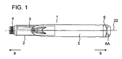
図1には、薬物送達デバイス1が示されている。薬物送達デバイス1は、ハウジング5を含む。ハウジング5は、デバイス1の、ハウジング5の内部に配置された構成要素を環境による影響から保護するように適用され、配置されている。薬物送達デバイス1、ならびにハウジング5は、遠位端8、および近位端9を有する。用語「遠位端」とは、薬物送達デバイス1、またはその構成要素の、投薬端の最も近くに配置された、または配置予定の端部を示す。用語「近位端」とは、デバイス1、またはその構成要素の、投薬端から最も離れて配置された、または配置予定の端部を示す。遠位端8と近位端9とは、軸22の方向に互いに離隔されている。軸22は、デバイス1の長手方向軸でも、回転軸でもよい。
In FIG. 1, a drug delivery device 1 is shown. The drug delivery device 1 includes a housing 5. The housing 5 is applied and arranged to protect the components of the device 1 arranged inside the housing 5 from environmental influences. The drug delivery device 1 and the housing 5 have a
薬物送達デバイス1は、カートリッジホルダ2を含む。カートリッジホルダ2は、カートリッジ3を含む。カートリッジ3は、薬物10、好ましくは複数の用量の薬物10を収容している。カートリッジ3は、カートリッジホルダ2の内部に保持されている。カートリッジホルダ2は、カートリッジ3の位置を機械的に安定させる。カートリッジホルダ2は、たとえばねじ係合によって、またはバヨネット連結によってハウジング5に連結可能である。カートリッジホルダ2とハウジング5とは、互いに解放可能に連結しても、解放不可能に連結してもよい。代替実施形態では、カートリッジ3は、ハウジング5に直接連結することができる。この場合、カートリッジホルダ2は冗長となり得る。
The drug delivery device 1 includes a
薬物送達デバイス1は、ペン型デバイス、特にペン型注射器でよい。デバイス1は、再使用可能なデバイスでよく、これは特にリセット動作中、カートリッジ3を、複数の用量を投薬するための取換えカートリッジと取り換えることができることを意味する。あるいは、デバイス1は使い捨てデバイスでもよい。デバイス1は、可変用量の薬物10を投薬するように構成することができる。あるいは、デバイス1は、定用量デバイスでもよい。デバイス1は、自動注射デバイスでよい。これは、使用者が起動部材6Aを押すことによって、デバイス1の用量送達動作を開始できることを意味し、ここで、起動部材6Aを押すとき、デバイス1に蓄積されたエネルギーが解放されて薬物10の用量が投薬されることになる。自動注射器は、カートリッジ3から全内容物を実質的に排出するように構成することができる。あるいは、自動注射器は、排出予定の薬物10の量を決定するように構成された用量設定部材6を含んでもよい。
The drug delivery device 1 may be a pen type device, in particular a pen type syringe. Device 1 may be a reusable device, which means that the cartridge 3 can be replaced with a replacement cartridge for dispensing multiple doses, especially during a reset operation. Alternatively, the device 1 may be a disposable device. Device 1 can be configured to dispense a variable dose of
栓11(図2参照)が、カートリッジ3の内部に摺動可能に保持されている。栓11は、カートリッジ3を近位方向に封止している。栓11がカートリッジ3に対して遠位方向に動くことによって、薬物10がカートリッジ3から投薬されることになる。ニードルアセンブリ(図には明示せず)を、たとえば、係合手段4、たとえばねじ山によってカートリッジホルダ2の遠位端部に配置することができる。
A stopper 11 (see FIG. 2) is slidably held inside the cartridge 3. The
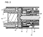
図2から図4は、図1の薬物送達デバイスの一部の側断面図を示している。 2-4 show side cross-sectional views of a portion of the drug delivery device of FIG.
デバイス1は、ピストンロッド12を含む。ピストンロッド12は、薬物10の用量を投薬するために、遠位方向に動くように構成されている。遠位方向とは、送達方向でよい。ピストンロッド12は、デバイス1の長手方向軸22に沿って動く。したがって、長手方向軸22は、ピストンロッド12が動く軸である。ピストンロッド12は、カートリッジ3内に配置された栓11を薬物送達デバイス1の投薬端の方へと動かすように構成されている。ピストンロッド12は、栓11と接触している支承部材13を含む。ピストンロッド12は、親ねじとして構成される。ピストンロッド12は、外側ねじ山12Aを含む。ねじ山12Aは、ピストンロッド12の外面に沿って配置されている。
Device 1 includes a
デバイス1は、駆動機能(drive feature)20をさらに含むことができる。駆動機能20は、ナット部材、たとえばスプラインナットでよい。駆動機能20は、ピストンロッド12と係合している。特に、駆動機能20は、ピストンロッド12の軸溝と係合するスプラインを含む。したがって、駆動機能20は、ピストンロッド12に対して回転方向に固定されているが、軸方向には可動である。駆動機能20、したがってピストンロッド12は、用量送達動作中、回転可能とすることができる。代替実施形態では、駆動機能20、およびピストンロッド12は、ハウジング5に対する回転方向の動きを防止することができる。
The device 1 may further include a
デバイス1は、ガイド部材14をさらに含む。ピストンロッド12は、ガイド部材14を通って案内される。ガイド部材14は、ピストンロッド12の周りに配置される。ガイド部材14は、ナット部材でよい。ガイド部材14は、好ましくはねじ山ナットとして構成される。ガイド部材14は、ピストンロッド12とねじ係合し、好ましくは恒久的にねじ係合している。この目的で、ガイド部材14は、ピストンロッド12の外側ねじ山12Aと係合している内側ねじ山を含む。ガイド部材14は、ハウジング5に対して動かないように固定されている。駆動機能20が、用量送達動作中に回転すると、ピストンロッド12もやはり回転する。ピストンロッド12とガイド部材14とがねじ係合しているため、ピストンロッド12の回転によって、ピストンロッド12が遠位方向に動くことになる。それによって、栓11が遠位方向に動き、薬物10の用量が投薬されることになる。
The device 1 further includes a
用量送達の前に、必要用量の薬物10が、用量設定機構によって設定される。用量設定機構の通常の設計では、用量設定スリーブ、用量指示スリーブ、駆動スリーブ、および/またはラチェットスリーブなどの、いくつかの管状またはスリーブ状の部材が含まれる。そのようなスリーブは、互いに入れ子になり、連結されていることが多い。
Prior to dose delivery, the required dose of
デバイス1、特に用量設定機構は、用量設定部材6を含む。用量設定部材6は、スリーブ状に成形することができる。用量設定部材6は、ハウジング5に対して軸方向に固定されているが、回転方向には可動である。用量設定部材6は、薬物10の用量を設定するように構成されている。用量設定部材6は、薬物10の用量を設定するようにハウジング5に対して回転可能である。用量設定部材6は、使用者が回転させることができる。用量設定部材6は、用量送達動作中、ハウジング5との機械的協働のため、ハウジング5に対する回転が防止される。
The device 1, in particular the dose setting mechanism, includes a dose setting member 6. The dose setting member 6 can be formed into a sleeve shape. The dose setting member 6 is fixed in the axial direction with respect to the housing 5, but is movable in the rotational direction. The dose setting member 6 is configured to set the dose of the
デバイス1は、駆動部材15をさらに含む。駆動部材15は、駆動軸を含むことができる。駆動部材15は、ピストンロッド12の周りに配置することができる。駆動部材15は、薬物10の用量を設定するように、用量設定部材6に連結されている。特に、駆動部材15は、用量設定動作中、スプライン連結のため、用量設定部材6に回転方向に固定することができる。したがって、用量設定動作中、用量設定部材6を回転させることによって、駆動部材15もやはり回転する。駆動部材15は、設定された用量を送達するために、用量設定部材6から連結解除(disconnect)することができ、これについては後に詳述する。駆動部材15は、用量送達中、回転可能である。
The device 1 further includes a
デバイス1は、回転部材19をさらに含む。回転部材19は、スリーブ状に成形されている。回転部材19は、ハウジング5に対して回転可能である。回転部材19は、駆動部材15の周りに同心に配置されている。回転部材19は、たとえばスナップ嵌め(snap−fit)連結によって駆動部材15に固定することができる。回転部材19は、駆動部材15に対して軸方向に固定されている。用量設定動作中、駆動部材15が回転することによって、回転部材19が回転する。この目的で、この回転部材は、ハウジング5の内側ねじ山(明示せず)と係合できるねじ山19Aを含む。駆動部材15、および回転部材19が用量設定中に回転する方向、すなわち第1の回転方向は、時計回り方向でよい。回転部材19が用量設定中に回転すると、回転部材19はハウジング5に対して近位方向に動く。駆動部材15、および回転部材19が用量送達中に回転する方向、すなわち第2の回転方向は、反時計回り方向でよい。
The device 1 further includes a rotating
使用者の使い心地を向上させるために、デバイス1は、動力補助、特にエネルギー蓄積部材16を含む。エネルギー蓄積部材16は、コイルばねでよい。エネルギー蓄積部材16は、ねじりばねでもよい。用量設定部材6、したがって回転部材19が用量設定中に回転すると、エネルギー蓄積部材16は圧縮し、したがってエネルギーがエネルギー蓄積部材16に蓄積されることになる。それにより、たとえばラチェットスリーブにある単一のラチェット(図には明示せず)によってカチッという音(clicking noise)が生じる。
In order to improve the user experience, the device 1 includes a power assist, in particular an
デバイス1は、ロッキング部材21(図2参照)をさらに含む。ロッキング部材21は、クラッチ部材でよい。ロッキング部材21は、用量の設定中、ハウジング5に対して固定される。特に、ロッキング部材21とハウジング5とは、対応する係合手段(図には明示せず)、たとえばスプラインを含むことができる。対応する係合手段は、用量の設定中、係合させることができる。回転部材19は、ロッキング部材21に連結(couple)されている。
The device 1 further includes a locking member 21 (see FIG. 2). The locking
ロッキング部材21は、用量の設定中、回転部材19が不意に回転するのを阻止するように構成されている。それによって、ロッキング部材21は、エネルギー蓄積部材16が弛緩するのを阻止している。この目的で、回転部材19は、噛合連結(toothed connection)(図には明示せず)によってロッキング部材21と係合させることができ、したがって回転部材19が、用量設定動作中、第1の回転方向に回転でき、かつ回転部材19が、用量設定動作中、第1の回転方向とは逆方向、すなわち第2の回転方向に回転するのが防止されることになる。あるいは、回転部材19は、ラチェット機構(図には明示せず)を含むことができる。回転部材19は、ラチェット機構によってロッキング部材21に連結することができる。ラチェット機構は、たとえば、ラチェットアームを含むことができる。ラチェットアームは、回転部材19が、用量設定中、不意に第2の回転方向に回転するのを阻止することができるように、ロッキング部材21と係合させることができる。しかし、このラチェット機構は、上述のように、用量を設定するために、回転部材19がロッキング部材21に対して第1の回転方向に回転するのは可能とする。
The locking
デバイス1は、先に述べた起動部材6Aをさらに含む。起動部材6Aは、ハウジング5に対して軸方向に可動である。起動部材6Aは、ハウジング5に対する回転方向の動きが防止されている。用量を投薬するために、使用者が起動部材6Aを動作させる。起動部材6Aは、ボタンを含むことができる。起動部材6Aが送達方向へと軸方向に動くと、エネルギー蓄積部材16が解放されてピストンロッド12を駆動し、薬物10の用量がカートリッジ3から送達されることになる。したがって、デバイス1の使用者は、投薬するために力を込める必要がない。
The device 1 further includes the
特に、起動部材6Aが起動する、たとえば遠位または送達方向に動くと、駆動部材15もやはり、遠位方向に動く。それによって、駆動部材15が動いて、用量設定部材6との係合が外れる。駆動部材15が遠位方向に動くと、回転部材19、およびロッキング部材21もやはり、遠位方向に動く。それによって、ロッキング部材21は、ハウジング5との係合から解除される。特に、ロッキング部材21は、使用者が起動部材6Aを作動させると、ハウジング5に対して回転することが可能となる。ロッキング部材21が回転することが可能となると、回転部材19、および駆動部材15も同様に回転することが可能となる。ロッキング部材21がハウジング5に対して回転することが可能となると、エネルギー蓄積部材16に蓄積されたエネルギーが解放されて、駆動部材15を回転させ、したがって回転部材19を遠位方向へと回転させる。回転部材19の回転によって、駆動機能20が回転することになり、したがってピストンロッド12が遠位方向へと回転方向に動き、薬物10の用量が投薬されることになる。
In particular, when the
従来の薬物送達デバイスでは、使用者は、用量送達動作中にピストンロッド12が動く速度、すなわち注射速度に対して制御することができない。特に、上述のロッキング部材21が解放されると、注射速度は、起動部材6Aの押し込みとは独立になる。しかし、注射速度を制御することは、たとえば薬物10が組織に注射されるときの痛みを低減させるために、使用者にとって望ましい。
In conventional drug delivery devices, the user cannot control the speed at which the
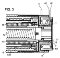
この目的で、デバイス1は、第1の相互作用部材17(図3および図4を参照)を含む。デバイス1は、第2の相互作用部材18(図3および図4参照)をさらに含む。第1および第2の相互作用部材17、18は、用量送達動作中、互いに機械的に協働するように構成されている。しかし、第1および第2の相互作用部材17、18は、用量設定動作中は機械的に協働することはない。第1および第2の相互作用部材17、18は、互いに回転可能である。第1および第2の相互作用部材17、18は、互いに軸方向に可動である。
For this purpose, the device 1 includes a first interaction member 17 (see FIGS. 3 and 4). The device 1 further includes a second interaction member 18 (see FIGS. 3 and 4). The first and
第1の相互作用部材17は、用量送達動作中、ハウジング5に対して、かつ第2の相互作用部材18に対して回転可能である。第1の相互作用部材17は、用量設定動作中も同様に、ハウジング5に対して回転可能とすることができる。第1の相互作用部材17は、たとえば、駆動部材15に連結することができる。あるいは、第1の相互作用部材17と駆動部材15とは、一体に形成してもよい。言い換えれば、第1の相互作用部材17は、駆動部材15の一部とすることができる。第1の相互作用部材17は、駆動部材15の近位端部に配置される。第1の相互作用部材17は、駆動部材15の近位端部の周辺周りに配置することができる。代替実施形態(明示せず)では、第1の相互作用部材17は、デバイスの用量送達動作中、回転可能かつ軸方向に可動な、デバイス1の他のいかなる部材に連結しても、その部材の一部としてもよい。
The
第1の相互作用部材17は、傾斜面7を含む。特に、第1の相互作用部材17は、長手方向軸22とある角度を成す表面7を含む。第1の相互作用部材17は、少なくとも1つのウェッジを含むことができる。ウェッジは、円形または部分的に円形のウェッジでよい。あるいは、第1の相互作用部材17は、複数のウェッジ、たとえば2つ、3つ、または4つの以上ウェッジを含むことができる。1つまたは複数のウェッジは、駆動部材15の近位端部の周りに配置することができる。
The
第2の相互作用部材18は、用量送達動作中、ハウジング5に対する回転が防止される。しかし、第2の相互作用部材18は、用量設定動作中、回転可能とすることができる。言い換えれば、少なくとも用量送達中、第1の相互作用部材17は、第2の相互作用部材18に対して回転可能である。第2の相互作用部材18は、たとえば、用量設定部材6に連結することができる。あるいは、第2の相互作用部材18と用量設定部材6とは、一体に形成してもよい。言い換えれば、第2の相互作用部材18は、用量設定部材6の一部とすることができる。第2の相互作用部材18は、用量設定部材6の近位端部に配置される。第2の相互作用部材18は、用量設定部材6の、第1の相互作用部材17に面した外面に配置される。代替実施形態(明示せず)では、第2の相互作用部材18は、デバイスの用量送達動作中、回転可能でもなく、軸方向に可動でもなく、かつ第1の相互作用部材17を含む構成要素の近位端部に面した、デバイス1の他のいかなる部材に連結しても、またはその部材の一部としてもよい。
The
第2の相互作用部材18は、傾斜面を含む。特に、第2の相互作用部材18は、長手方向軸22とある角度を成す表面を含む。この傾斜面は、第2の相互作用部材18の、第1の相互作用部材17に面する表面でよい。
The
相互作用部材17、18は、用量送達中、機械的に協働して、相互作用部材17、18間で摩擦が生じるように構成される。この摩擦の量は、第1の相互作用部材17の回転速度に影響を及ぼす。言い換えれば、摩擦の量は、用量送達中の、相互作用部材17、18の相対回転速度に影響を及ぼす。相互作用部材17、18間の摩擦が大きくなるほど、回転速度は低くなる。相対回転速度が低くなるほど、用量送達中の、駆動部材15、および回転部材19の回転速度もより低くなる。用量送達中の回転部材19の動きがピストンロッド12の動きに変換されるため、ピストンロッド12が動く速度に影響が及ぼされ、特に速度が低減し、これは、相互作用部材17、18が機械的に協働するためである。
The
相互作用部材17、18を機械的に協働させるには、使用者が用量送達動作を開始しなければならない。この目的で、使用者は起動部材6Aを遠位に押す。起動部材6Aが遠位に動くとき、駆動部材15、したがって第1の相互作用部材17も同様に遠位に動く。第1の相互作用部材17は、第2の相互作用部材18の方へと遠位に動く。しかし、相互作用部材17、18は、起動部材6Aが遠位に動くとすぐに機械的に接触するわけではない。そうではなく、起動部材6A、したがって駆動部材15は、相互作用部材17、18を機械的に接触させるには、ある距離だけ動かなければならない。
In order for the
特に、起動部材6Aは、第1の位置から第2の位置へと第1の距離d1(図3参照)だけ動く。第1の位置は、開始位置、すなわち起動部材6Aが、使用者が起動部材6Aを押し込む前にハウジング5に対して配置されていた位置でよい。第2の位置は、中間位置でよい。第2の位置は、相互作用部材17、18が互いに機械的に協働し始める、起動部材6Aのハウジング5に対する位置でよい。起動部材6Aが第1および第2の位置間で動く距離d1は、起動部材6Aが薬物10の用量を送達するために可動である全距離dの半分でよい。あるいは、起動部材6Aが第1および第2の位置間で動く距離d1は、たとえば、起動部材6Aが薬物10の用量を送達するために可動である全距離dの3分の1でもよい。第1の距離d1は、全距離dよりも小さい。第1の距離d1は、たとえば、第1の相互作用部材17の表面が長手方向軸22と成す角度に依存することができる。この角度が大きいほど、第1の距離d1はより小さくてもよい。したがって、第1の距離d1は、可変距離であり、デバイスの構成要素の構造に依存する。したがって、第2の位置は、可変位置である。
In particular, the actuating
起動部材6Aが第1の位置から第2の位置の方へと動くと、駆動部材15が遠位に動き、したがってロッキング部材21がハウジング5から係合解除される。したがって、エネルギー蓄積部材16は弛緩することができ、その結果、駆動部材15、および回転部材19が上述のように回転方向に動くことになる。
As the
起動部材6Aが第2の位置にあるとき、第1および第2の相互作用部材17、18は機械的に協働し始める。したがって、相互作用部材17、18は、ロッキング部材21がハウジング5から係合解除された瞬間すぐに、またはその後、機械的に協働する。第1の相互作用部材17は第2の相互作用部材18に対して回転可能であるので、相互作用部材17、18が接触すると、相互作用部材17、18間で摩擦が生じる。摩擦の量は、相互作用部材17、18の相対的な軸方向の位置に依存し、したがって、相互作用部材17、18間の機械的な協働の程度に依存する。摩擦の量は、起動部材6Aの軸方向の位置に依存する。
When the
起動部材6Aが第2の位置に配置されているとき、起動部材6Aは最終位置、すなわちハウジング5に対して第3の位置にはまだ到達していない。最終位置、すなわち第3の位置は、起動部材6Aが送達動作終了時に配置される位置でよい。起動部材6Aは、第2の位置と第3の位置との間で第2の距離d2(図3参照)だけ可動である。起動部材6Aが第2および第3の位置間で動く第2の距離d2は、起動部材6Aが薬物10の用量を送達するために可動な全距離dの半分でよい。第2の距離d2は、第1の距離d1に等しくてもよい。あるいは、第2の距離d2は、第1の距離d1よりも大きくてもよい。第1の距離d1と第2の距離d2との合計は、全距離dに等しい。
When the activation member 6 </ b> A is disposed at the second position, the activation member 6 </ b> A has not yet reached the final position, i.e., the third position with respect to the housing 5. The final position, that is, the third position may be a position where the
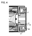
第3の位置では、起動部材6Aは、用量設定部材6の近位端面と当接することができる(図4参照)。したがって、用量設定部材6は、起動部材6Aの遠位方向の動きを制限することができる。あるいは、相互作用部材17、18によって、用量送達中の起動部材6Aの遠位方向の動きを制限してもよい。第2の距離d2は、たとえば、第1の相互作用部材17の表面7が長手方向軸22と成す角度に依存することができる。この角度が所定の角度、たとえば45度を超えると、起動部材6Aが用量設定部材6と当接するのではなく、相互作用部材17、18が機械的に協働するため、起動部材6Aの遠位方向の動きが停止する。したがって、第2の距離d2は、可変距離でよい。第3の位置は、可変位置でよい。
In the third position, the
起動部材6Aが第2の位置から第3の位置へとさらに動くとき、相互作用部材17、18間の接触面積が増大する。したがって、相互作用部材17、18間の摩擦の量が増大する。したがって、使用者が起動部材6Aを押し込むほど、より多くの摩擦が生じることになり、したがって相互作用部材17、18の相対回転速度がより低くなる。相互作用部材17、18の相対回転速度が減速すると、ピストンロッド12が動く速度も同様に減速する。したがって、用量送達中に起動部材6Aが遠位に動く距離を制御することによって、使用者はデバイス1の注射速度を制御することができる。
As the
他の実装形態が、以下の特許請求の範囲内に含まれる。異なる実装形態の諸要素を組み合わせて、本明細書に具体的には記載されていない実装形態を形成してもよい。 Other implementations are within the scope of the following claims. Elements of different implementations may be combined to form implementations not specifically described herein.
1 薬物送達デバイス
2 カートリッジホルダ
3 カートリッジ
4 係合手段
5 ハウジング
6A 起動部材
6 用量設定部材
7 傾斜面
8 遠位端
9 近位端
10 薬物
11 栓
12 ピストンロッド
13 支承部材
14 ガイド部材
15 駆動部材
16 エネルギー蓄積部材
17 第1の相互作用部材
18 第2の相互作用部材
19 回転部材
19A ねじ山
20 駆動機能
21 ロッキング部材
22 長手方向軸
d 距離
d1 第1の距離
d2 第2の距離
DESCRIPTION OF SYMBOLS 1
Claims (14)
− 該アセンブリの用量送達動作をトリガするように、送達方向へと軸方向に動くように適用され、配置された起動部材(6A)と、
− 該アセンブリの用量送達動作中、互いに機械的に協働し、かつ用量送達動作中、互いに回転するように適用され、配置された第1の相互作用部材(17)、および第2の相互作用部材(18)と
を含み、ここで、該アセンブリは、起動部材(6A)が送達方向に動くことによって、相互作用部材(17、18)が機械的に接触して相互作用部材(17、18)間で摩擦が生じるように構成され、ここで、摩擦の量によって、用量送達動作中の相互作用部材(17、18)の相対回転速度を制御する、前記薬物送達デバイス用アセンブリ。 An assembly for a drug delivery device (1) comprising:
An activation member (6A) adapted and arranged to move axially in the delivery direction to trigger a dose delivery action of the assembly;
A first interaction member (17) and a second interaction adapted and arranged to mechanically cooperate with each other during the dose delivery operation of the assembly and to rotate with respect to each other during the dose delivery operation; The assembly (18), wherein the assembly comprises the interaction member (17, 18) in mechanical contact with the interaction member (17, 18) by movement of the activation member (6A) in the delivery direction. ), Wherein the relative rotational speed of the interaction member (17, 18) during dose delivery operation is controlled by the amount of friction.
− エネルギーを蓄積し、かつピストンロッド(12)を送達方向に動かすように適用され、配置されたエネルギー蓄積部材(16)と
をさらに含み、ここで、相互作用部材(17、18)間で生じる摩擦の量によって、用量送達動作中にピストンロッド(12)が動く速度を制御する、請求項1〜9のいずれか1項に記載のアセンブリ。 A piston rod (12) applied and arranged to move in the direction of delivery to dispense a dose of drug (10) from the device;
-Energy storage and further comprising an energy storage member (16) applied and arranged to move the piston rod (12) in the delivery direction, where it occurs between the interaction members (17, 18) The assembly according to any one of the preceding claims, wherein the amount of friction controls the speed at which the piston rod (12) moves during a dose delivery operation.
複数の用量の薬物(10)を保持するためのカートリッジ(3)をさらに含む、前記薬物送達デバイス。 A drug delivery device (1) comprising an assembly according to any one of claims 1-13,
Said drug delivery device further comprising a cartridge (3) for holding a plurality of doses of drug (10).
Applications Claiming Priority (3)
| Application Number | Priority Date | Filing Date | Title |
|---|---|---|---|
| EP13198704.2 | 2013-12-20 | ||
| EP13198704 | 2013-12-20 | ||
| PCT/EP2014/078415 WO2015091763A1 (en) | 2013-12-20 | 2014-12-18 | Assembly for a drug delivery device and drug delivery device |
Publications (2)
| Publication Number | Publication Date |
|---|---|
| JP2017501801A true JP2017501801A (en) | 2017-01-19 |
| JP2017501801A5 JP2017501801A5 (en) | 2018-01-25 |
Family
ID=49880493
Family Applications (1)
| Application Number | Title | Priority Date | Filing Date |
|---|---|---|---|
| JP2016541261A Abandoned JP2017501801A (en) | 2013-12-20 | 2014-12-18 | Drug delivery device assembly and drug delivery device |
Country Status (6)
| Country | Link |
|---|---|
| US (1) | US10159801B2 (en) |
| EP (1) | EP3082910B1 (en) |
| JP (1) | JP2017501801A (en) |
| CN (1) | CN106029131A (en) |
| HK (1) | HK1225673A1 (en) |
| WO (1) | WO2015091763A1 (en) |
Families Citing this family (6)
| Publication number | Priority date | Publication date | Assignee | Title |
|---|---|---|---|---|
| KR20160088881A (en) * | 2013-11-22 | 2016-07-26 | 사노피-아벤티스 도이칠란트 게엠베하 | Drug delivery device |
| CN105960256A (en) * | 2013-12-20 | 2016-09-21 | 赛诺菲-安万特德国有限公司 | Assembly for drug delivery device and drug delivery device |
| DE202015006844U1 (en) * | 2015-09-30 | 2016-01-15 | Haselmeier Ag | injection device |
| PL414382A1 (en) * | 2015-10-15 | 2017-04-24 | Copernicus Spółka Z Ograniczoną Odpowiedzialnością | Setting mechanism, in particular for dosing |
| WO2019192662A1 (en) * | 2018-04-04 | 2019-10-10 | Cpu Innovation Aps | Auto injector with improved functionality |
| CN108837196B (en) * | 2018-07-26 | 2020-09-08 | 陈澜涛 | Needle cylinder capable of realizing constant-speed suction |
Family Cites Families (56)
| Publication number | Priority date | Publication date | Assignee | Title |
|---|---|---|---|---|
| US533575A (en) | 1895-02-05 | wilkens | ||
| DE3715258C2 (en) | 1987-05-08 | 1996-10-31 | Haselmeier Wilhelm Fa | Injection device |
| GB8713810D0 (en) | 1987-06-12 | 1987-07-15 | Hypoguard Uk Ltd | Measured dose dispensing device |
| US5226895A (en) | 1989-06-05 | 1993-07-13 | Eli Lilly And Company | Multiple dose injection pen |
| GB9007113D0 (en) | 1990-03-29 | 1990-05-30 | Sams Bernard | Dispensing device |
| US5226896A (en) | 1990-04-04 | 1993-07-13 | Eli Lilly And Company | Dose indicating injection pen |
| AU641206B2 (en) | 1991-01-22 | 1993-09-16 | Eli Lilly And Company | Multiple dose injection pen |
| DK0525525T3 (en) | 1991-07-24 | 1995-10-02 | Medico Dev Investment Co | Injector |
| DK175491D0 (en) | 1991-10-18 | 1991-10-18 | Novo Nordisk As | APPARATUS |
| US5279586A (en) | 1992-02-04 | 1994-01-18 | Becton, Dickinson And Company | Reusable medication delivery pen |
| US5271527A (en) | 1992-04-02 | 1993-12-21 | Habley Medical Technology Corporation | Reusable pharmaceutical dispenser with full stroke indicator |
| US5300041A (en) | 1992-06-01 | 1994-04-05 | Habley Medical Technology Corporation | Dose setting and repeating syringe |
| US5391157A (en) | 1992-10-20 | 1995-02-21 | Eli Lilly And Company | End of dose indicator |
| US5378233A (en) | 1992-11-18 | 1995-01-03 | Habley Medical Technology Corporation | Selected dose pharmaceutical dispenser |
| US5320609A (en) | 1992-12-07 | 1994-06-14 | Habley Medical Technology Corporation | Automatic pharmaceutical dispensing syringe |
| FR2701211B1 (en) | 1993-02-08 | 1995-05-24 | Aguettant Lab | DOSING INSTRUMENT, ESPECIALLY INJECTION |
| US5383865A (en) | 1993-03-15 | 1995-01-24 | Eli Lilly And Company | Medication dispensing device |
| ZA941881B (en) | 1993-04-02 | 1995-09-18 | Lilly Co Eli | Manifold medication injection apparatus and method |
| US5582598A (en) | 1994-09-19 | 1996-12-10 | Becton Dickinson And Company | Medication delivery pen with variable increment dose scale |
| NZ302558A (en) | 1995-03-07 | 1999-11-29 | Lilly Co Eli | Dispensing apparatus with a medication cartridge with a manually adjustable metering mechanism |
| AU1860697A (en) | 1995-09-08 | 1997-07-28 | Visionary Medical Products Corporation | Pen-type injector drive mechanism |
| US5688251A (en) | 1995-09-19 | 1997-11-18 | Becton Dickinson And Company | Cartridge loading and priming mechanism for a pen injector |
| US5674204A (en) | 1995-09-19 | 1997-10-07 | Becton Dickinson And Company | Medication delivery pen cap actuated dose delivery clutch |
| US5851079A (en) | 1996-10-25 | 1998-12-22 | The Procter & Gamble Company | Simplified undirectional twist-up dispensing device with incremental dosing |
| DE19730999C1 (en) | 1997-07-18 | 1998-12-10 | Disetronic Licensing Ag | Injection pen dosing selected volume of fluid, especially insulin |
| US5957896A (en) | 1997-08-11 | 1999-09-28 | Becton, Dickinson And Company | Medication delivery pen |
| HU222513B1 (en) | 1998-01-30 | 2003-08-28 | Novo Nordisk A/S | An injection syringe |
| US5961495A (en) | 1998-02-20 | 1999-10-05 | Becton, Dickinson And Company | Medication delivery pen having a priming mechanism |
| US6221053B1 (en) | 1998-02-20 | 2001-04-24 | Becton, Dickinson And Company | Multi-featured medication delivery pen |
| US6248095B1 (en) | 1998-02-23 | 2001-06-19 | Becton, Dickinson And Company | Low-cost medication delivery pen |
| DE19900827C1 (en) | 1999-01-12 | 2000-08-17 | Disetronic Licensing Ag | Device for the dosed administration of an injectable product |
| DE19900792C1 (en) | 1999-01-12 | 2000-06-15 | Disetronic Licensing Ag | Injection unit forming part of e.g. pen-type self-injection syringe has continuous dosing stop in spiral form with constant pitch ensuring close fine control and accuracy in use |
| DE29900482U1 (en) | 1999-01-14 | 2000-08-31 | Medico Dev Investment Co | Injection device |
| SE9901366D0 (en) | 1999-04-16 | 1999-04-16 | Pharmacia & Upjohn Ab | Injector device and method for its operation |
| ATE318157T1 (en) | 1999-08-05 | 2006-03-15 | Becton Dickinson Co | PEN-SHAPED MEDICATION DELIVERY DEVICE |
| GB0007071D0 (en) | 2000-03-24 | 2000-05-17 | Sams Bernard | One-way clutch mechanisms and injector devices |
| US6663602B2 (en) | 2000-06-16 | 2003-12-16 | Novo Nordisk A/S | Injection device |
| NZ539404A (en) | 2000-10-09 | 2007-05-31 | Lilly Co Eli | Pen device for administration of parathyroid hormone |
| US6899699B2 (en) | 2001-01-05 | 2005-05-31 | Novo Nordisk A/S | Automatic injection device with reset feature |
| PT2258424E (en) | 2001-05-16 | 2013-03-28 | Lilly Co Eli | Medication injector apparatus |
| AU2003216521A1 (en) | 2002-03-18 | 2003-10-08 | Eli Lilly And Company | Medication dispensing apparatus with gear set for mechanical advantage |
| US7169132B2 (en) | 2002-10-01 | 2007-01-30 | Becton, Dickinson And Company | Medication delivery pen |
| GB0304823D0 (en) | 2003-03-03 | 2003-04-09 | Dca Internat Ltd | Improvements in and relating to a pen-type injector |
| US6932794B2 (en) | 2003-04-03 | 2005-08-23 | Becton, Dickinson And Company | Medication delivery pen |
| EP1541185A1 (en) | 2003-12-08 | 2005-06-15 | Novo Nordisk A/S | Automatic syringe with priming mechanism |
| DE102004063648A1 (en) | 2004-12-31 | 2006-07-20 | Tecpharma Licensing Ag | Injection or infusion device with life-determining device |
| CA2594764C (en) | 2005-01-21 | 2014-01-14 | Novo Nordisk A/S | An automatic injection device with a top release mechanism |
| CN101115520B (en) | 2005-02-11 | 2010-04-21 | 诺和诺德公司 | Injection device |
| GB2443390A (en) * | 2006-11-03 | 2008-05-07 | Owen Mumford Ltd | Medicine delivery apparatus |
| GB0802351D0 (en) | 2008-02-08 | 2008-03-12 | Owen Mumford Ltd | Injection devices |
| DE102008011881A1 (en) * | 2008-02-29 | 2009-09-10 | Tecpharma Licensing Ag | Empty shooting speed limit brake |
| US8187233B2 (en) | 2008-05-02 | 2012-05-29 | Sanofi-Aventis Deutschland Gmbh | Medication delivery device |
| US8647309B2 (en) | 2008-05-02 | 2014-02-11 | Sanofi-Aventis Deutschland Gmbh | Medication delivery device |
| KR200454414Y1 (en) * | 2009-10-07 | 2011-07-01 | 주식회사 대웅제약 | Medicine syringe |
| GB2487178A (en) * | 2010-11-09 | 2012-07-18 | Medical House Ltd | Device for attaching a needle to an autoinjector syringe |
| TWI645875B (en) * | 2013-04-10 | 2019-01-01 | 法商賽諾菲公司 | Dispensing speed control mechanism and injection device |
-
2014
- 2014-12-18 CN CN201480075624.8A patent/CN106029131A/en active Pending
- 2014-12-18 EP EP14814875.2A patent/EP3082910B1/en active Active
- 2014-12-18 WO PCT/EP2014/078415 patent/WO2015091763A1/en active Application Filing
- 2014-12-18 US US15/105,738 patent/US10159801B2/en active Active
- 2014-12-18 JP JP2016541261A patent/JP2017501801A/en not_active Abandoned
-
2016
- 2016-12-13 HK HK16114138A patent/HK1225673A1/en unknown
Also Published As
| Publication number | Publication date |
|---|---|
| EP3082910A1 (en) | 2016-10-26 |
| CN106029131A (en) | 2016-10-12 |
| WO2015091763A1 (en) | 2015-06-25 |
| US10159801B2 (en) | 2018-12-25 |
| US20160317753A1 (en) | 2016-11-03 |
| HK1225673A1 (en) | 2017-09-15 |
| EP3082910B1 (en) | 2020-03-04 |
Similar Documents
| Publication | Publication Date | Title |
|---|---|---|
| JP6567525B2 (en) | Drive mechanism of drug delivery device | |
| JP6261519B2 (en) | Fixed dose drug delivery device | |
| JP6448624B2 (en) | Drive assembly for drug delivery device and drug delivery device | |
| JP6556636B2 (en) | Drive mechanism for a drug delivery device | |
| JP6490057B2 (en) | Drug delivery device assembly and drug delivery device | |
| JP2016540582A (en) | Assembly for drug delivery device and drug delivery device | |
| JP2019051388A (en) | Drive mechanism for drug delivery device and drug delivery device | |
| JP2017501801A (en) | Drug delivery device assembly and drug delivery device | |
| JP5818882B2 (en) | Drive mechanism for drug delivery device and drug delivery device | |
| JP6433484B2 (en) | Drive mechanism of drug delivery device | |
| JP6480460B2 (en) | Assembly for a drug delivery device | |
| JP6386481B2 (en) | Assembly for a drug delivery device | |
| JP2016525404A (en) | Drive unit for drug delivery device | |
| JP6448623B2 (en) | Assembly for a drug delivery device and drug delivery device | |
| US10293111B2 (en) | Drive mechanism for a drug delivery device and a method for assembling a drug delivery device | |
| JP6235558B2 (en) | Drug delivery device assembly and drug delivery device | |
| JP2016528000A (en) | Use of assemblies and damping members for drug delivery devices | |
| JP6722587B2 (en) | Assembly for drug delivery device, and drug delivery device | |
| JP6352316B2 (en) | Assembly for a drug delivery device | |
| CN106999674B (en) | Assembly for a drug delivery device and drug delivery device | |
| EP3082913B1 (en) | Assembly for a drug delivery device and drug delivery device | |
| JP2016526991A (en) | Drug delivery device counting mechanism |
Legal Events
| Date | Code | Title | Description |
|---|---|---|---|
| A521 | Request for written amendment filed |
Free format text: JAPANESE INTERMEDIATE CODE: A523 Effective date: 20171208 |
|
| A621 | Written request for application examination |
Free format text: JAPANESE INTERMEDIATE CODE: A621 Effective date: 20171208 |
|
| A762 | Written abandonment of application |
Free format text: JAPANESE INTERMEDIATE CODE: A762 Effective date: 20180903 |