JP2017501779A - Product dispensing system - Google Patents
Product dispensing system Download PDFInfo
- Publication number
- JP2017501779A JP2017501779A JP2016536575A JP2016536575A JP2017501779A JP 2017501779 A JP2017501779 A JP 2017501779A JP 2016536575 A JP2016536575 A JP 2016536575A JP 2016536575 A JP2016536575 A JP 2016536575A JP 2017501779 A JP2017501779 A JP 2017501779A
- Authority
- JP
- Japan
- Prior art keywords
- fluid
- dispensing system
- fluid reservoir
- reservoir
- piston head
- Prior art date
- Legal status (The legal status is an assumption and is not a legal conclusion. Google has not performed a legal analysis and makes no representation as to the accuracy of the status listed.)
- Granted
Links
- 239000012530 fluid Substances 0.000 claims abstract description 163
- 238000000034 method Methods 0.000 claims abstract description 10
- 238000009434 installation Methods 0.000 claims description 28
- 230000008878 coupling Effects 0.000 claims description 4
- 238000010168 coupling process Methods 0.000 claims description 4
- 238000005859 coupling reaction Methods 0.000 claims description 4
- 238000012423 maintenance Methods 0.000 claims description 4
- 239000007788 liquid Substances 0.000 claims description 3
- 239000003566 sealing material Substances 0.000 claims description 3
- 239000000344 soap Substances 0.000 description 13
- 230000006870 function Effects 0.000 description 6
- 239000012080 ambient air Substances 0.000 description 4
- 239000003570 air Substances 0.000 description 3
- 230000008569 process Effects 0.000 description 3
- 241000894006 Bacteria Species 0.000 description 1
- 230000005355 Hall effect Effects 0.000 description 1
- 230000004913 activation Effects 0.000 description 1
- 239000007844 bleaching agent Substances 0.000 description 1
- 238000004891 communication Methods 0.000 description 1
- 230000007797 corrosion Effects 0.000 description 1
- 238000005260 corrosion Methods 0.000 description 1
- 238000013500 data storage Methods 0.000 description 1
- 238000001514 detection method Methods 0.000 description 1
- 230000000694 effects Effects 0.000 description 1
- 238000000605 extraction Methods 0.000 description 1
- 229920002457 flexible plastic Polymers 0.000 description 1
- 230000000977 initiatory effect Effects 0.000 description 1
- 239000006210 lotion Substances 0.000 description 1
- 239000000463 material Substances 0.000 description 1
- 230000013011 mating Effects 0.000 description 1
- 230000007246 mechanism Effects 0.000 description 1
- 239000002184 metal Substances 0.000 description 1
- 230000003287 optical effect Effects 0.000 description 1
- 239000007800 oxidant agent Substances 0.000 description 1
- 229920003023 plastic Polymers 0.000 description 1
- 238000010926 purge Methods 0.000 description 1
- 238000005067 remediation Methods 0.000 description 1
- 238000005406 washing Methods 0.000 description 1
- 239000002699 waste material Substances 0.000 description 1
- XLYOFNOQVPJJNP-UHFFFAOYSA-N water Substances O XLYOFNOQVPJJNP-UHFFFAOYSA-N 0.000 description 1
Images


Classifications
-
- A—HUMAN NECESSITIES
- A47—FURNITURE; DOMESTIC ARTICLES OR APPLIANCES; COFFEE MILLS; SPICE MILLS; SUCTION CLEANERS IN GENERAL
- A47K—SANITARY EQUIPMENT NOT OTHERWISE PROVIDED FOR; TOILET ACCESSORIES
- A47K5/00—Holders or dispensers for soap, toothpaste, or the like
- A47K5/06—Dispensers for soap
- A47K5/12—Dispensers for soap for liquid or pasty soap
- A47K5/1211—Dispensers for soap for liquid or pasty soap using pressure on soap, e.g. with piston
- A47K5/1212—Dispensers for soap for liquid or pasty soap using pressure on soap, e.g. with piston applied by a screwing action
-
- A—HUMAN NECESSITIES
- A47—FURNITURE; DOMESTIC ARTICLES OR APPLIANCES; COFFEE MILLS; SPICE MILLS; SUCTION CLEANERS IN GENERAL
- A47K—SANITARY EQUIPMENT NOT OTHERWISE PROVIDED FOR; TOILET ACCESSORIES
- A47K5/00—Holders or dispensers for soap, toothpaste, or the like
- A47K5/06—Dispensers for soap
- A47K5/12—Dispensers for soap for liquid or pasty soap
- A47K5/1211—Dispensers for soap for liquid or pasty soap using pressure on soap, e.g. with piston
-
- A—HUMAN NECESSITIES
- A47—FURNITURE; DOMESTIC ARTICLES OR APPLIANCES; COFFEE MILLS; SPICE MILLS; SUCTION CLEANERS IN GENERAL
- A47K—SANITARY EQUIPMENT NOT OTHERWISE PROVIDED FOR; TOILET ACCESSORIES
- A47K5/00—Holders or dispensers for soap, toothpaste, or the like
- A47K5/06—Dispensers for soap
- A47K5/12—Dispensers for soap for liquid or pasty soap
- A47K5/1217—Electrical control means for the dispensing mechanism
-
- B—PERFORMING OPERATIONS; TRANSPORTING
- B67—OPENING, CLOSING OR CLEANING BOTTLES, JARS OR SIMILAR CONTAINERS; LIQUID HANDLING
- B67D—DISPENSING, DELIVERING OR TRANSFERRING LIQUIDS, NOT OTHERWISE PROVIDED FOR
- B67D7/00—Apparatus or devices for transferring liquids from bulk storage containers or reservoirs into vehicles or into portable containers, e.g. for retail sale purposes
- B67D7/02—Apparatus or devices for transferring liquids from bulk storage containers or reservoirs into vehicles or into portable containers, e.g. for retail sale purposes for transferring liquids other than fuel or lubricants
- B67D7/0288—Container connection means
- B67D7/0294—Combined with valves
-
- A—HUMAN NECESSITIES
- A47—FURNITURE; DOMESTIC ARTICLES OR APPLIANCES; COFFEE MILLS; SPICE MILLS; SUCTION CLEANERS IN GENERAL
- A47K—SANITARY EQUIPMENT NOT OTHERWISE PROVIDED FOR; TOILET ACCESSORIES
- A47K5/00—Holders or dispensers for soap, toothpaste, or the like
- A47K5/06—Dispensers for soap
- A47K5/12—Dispensers for soap for liquid or pasty soap
- A47K2005/1218—Table mounted; Dispensers integrated with the mixing tap
Abstract
流体分注システム,流体リザーバ,流体リザーバへの補給用の補給容器,ならびに,流体リザーバに補給する方法を提供する。流体分注システムは,流体リザーバへの補給の際に補給容器が接続される補給接続ポート又はノズルを備える。流体リザーバは,ピストンヘッドと,ピストンヘッドを第1の方向と第2の方向に動かすためのアクチュエータと,を有する。ピストンヘッドが第1の方向に動かされると,流体リザーバ内の流体は加圧されて,これにより流体は流体リザーバの出口を通って分注される。ピストンヘッドが第2の方向に動かされると,流体リザーバ内に真空が生じて,これにより補給容器からの流体が流体リザーバ内に引き込まれる。流体分注システムは,複数のリザーバをノズル及び/又は補給接続ポートに接続することを可能とするための弁を備える。【選択図】図1A fluid dispensing system, a fluid reservoir, a refill container for refilling a fluid reservoir, and a method for refilling a fluid reservoir are provided. The fluid dispensing system includes a replenishment connection port or nozzle to which a refill container is connected when refilling the fluid reservoir. The fluid reservoir has a piston head and an actuator for moving the piston head in a first direction and a second direction. When the piston head is moved in the first direction, the fluid in the fluid reservoir is pressurized, thereby dispensing the fluid through the outlet of the fluid reservoir. When the piston head is moved in the second direction, a vacuum is created in the fluid reservoir, thereby drawing fluid from the refill container into the fluid reservoir. The fluid dispensing system includes a valve to allow a plurality of reservoirs to be connected to the nozzle and / or refill connection port. [Selection] Figure 1
Description
関連出願
本出願は,「製品分注システム(PRODUCT DISPENSING SYSTEM)」という名称で2013年12月5日に出願された米国仮特許出願第61/912,052号の優先権を主張するものであり,この出願は,ここに参照することにより本明細書に援用される。
RELATED APPLICATION This application claims priority to US Provisional Patent Application No. 61 / 912,052, filed December 5, 2013 under the name "PRODUCT DISPENSING SYSTEM". This application is hereby incorporated by reference herein.
本発明は,広義には,衛生的なバルクソープ(bulk soap)ディスペンサに関し,特に,複数の補給リザーバ及び気密性の補給接続部(air-tight refill connections)を有する分注システムに関するものである。 The present invention relates generally to sanitary bulk soap dispensers, and more particularly to dispensing systems having a plurality of refill reservoirs and air-tight refill connections.
公衆が利用できる施設で,洗面所及びその他のエリアにソープディスペンサを設置することは一般的なことである。多くのディスペンサは,大気に開放されたリザーバを備えている。そのようなリザーバは,ボトル又はポットに貯蔵されているバルクソープから容易かつ経済的に補給される。ところが,大気に開放されて時間が経過したソープの容器は,不衛生なバイオフィルム(bio-films;ヌメリ,生体膜又はスライム)が発生することが,研究によって明らかになっている。これらの容器から使用されるソープは,実際に,その使用中にユーザの手に細菌を付着させる。前記リザーバを洗浄した後であっても,漂白剤のような強力な酸化剤を使用しているにもかかわらず,バイオフィルムが再発生することが,レメディエーション(修復:remediation)の研究によって明らかになっている。 It is common to install soap dispensers in washrooms and other areas where public access is available. Many dispensers have a reservoir open to the atmosphere. Such reservoirs are easily and economically replenished from bulk soap stored in bottles or pots. However, research has shown that uncleaned bio-films are produced in soap containers that have been opened to the atmosphere for a long time. The soap used from these containers actually attaches bacteria to the user's hand during its use. Remediation studies show that biofilms re-emerge even after washing the reservoir, despite the use of strong oxidants such as bleach. It has become.
上部開放型ディスペンサの弊害を克服するため,一部のディスペンサでは,システムへの補充の際に,リザーバには補給はされない。これらのシステムは,衛生的な環境で生産された使い捨ての補給ユニットを収納するように設計されている。製品が空になると,リザーバ全体が,付属のノズル及びポンプと共に交換される。このようにして,ディスペンサへの補充の際に,ソープで濡れた部分はすべて廃棄される。これによって,バイオフィルムの発生は大幅に抑制及び/又は解消される。しかしながら,リザーバに残存するソープの量,及びその交換時期を特定することが難しい場合がある。空になる前にリザーバが交換されると,製品が無駄になる。ディスペンサでソープを使い切ると,ユーザが手をきれいにすることができなくなる。 To overcome the negative effects of top open dispensers, some dispensers do not refill the reservoir when the system is refilled. These systems are designed to house disposable refill units produced in a hygienic environment. When the product is empty, the entire reservoir is replaced with the attached nozzle and pump. In this way, all parts wet with soap are discarded when the dispenser is refilled. This greatly reduces and / or eliminates biofilm generation. However, it may be difficult to determine the amount of soap remaining in the reservoir and when to replace it. If the reservoir is replaced before it is emptied, the product is wasted. When the soap is used up with the dispenser, the user cannot clean his hands.
リザーバ又は製品を周囲の空気にさらすことなく,かつ使用を中断させることなく,又は製品を使い切ることなく,適時にソープリザーバに補充する方法が必要とされている。本明細書に記載の発明の実施形態によって,上記の問題を解消する。 There is a need for a method for replenishing a soap reservoir in a timely manner without exposing the reservoir or product to ambient air and without interrupting or using up the product. The above-described problems are solved by the embodiments of the invention described herein.
本発明の一実施形態において,流体製品分注システムを提供し,これは,流体製品を保持するための複数のリザーバを備え,貯蔵及び送出システムは,周囲空気にさらされないように密封されている。本システムは,密封された衛生的な補給容器から補充されることができ,補給容器は,分注システムに流体接続されたポートに接続される。複数のリザーバのいずれかが空であるときには,分注システムは,自動的に他のリザーバから製品を分注するように機能する。 In one embodiment of the present invention, a fluid product dispensing system is provided that includes a plurality of reservoirs for holding fluid products and the storage and delivery system is sealed from exposure to ambient air. . The system can be refilled from a sealed sanitary refill container, which is connected to a port fluidly connected to the dispensing system. When any of the reservoirs is empty, the dispensing system functions to automatically dispense the product from the other reservoir.
具体的な一実施形態では,据付設備に,分注システムへの補給用のポートが設けられるとともに,製品を分注するのに用いられるノズルが別に設けられる。 In a specific embodiment, the installation facility is provided with a port for replenishment to the dispensing system and a separate nozzle used to dispense the product.
分注システムの他の実施形態では,分注ノズルを介して,分注システムに補給される。 In another embodiment of the dispensing system, the dispensing system is replenished via a dispensing nozzle.
詳細な説明
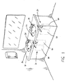
図1に示す製品分注システムは,本発明の実施形態により,一定量の流体製品を分注する。典型的な一例では,全体を符号10で示す分注システムは,ソープ,ローション,又はサニタイザのような,ハンドケア製品を分注するものであるが,同様に,分注システムは,他の種類の製品を分注するものであってもよい。
DETAILED DESCRIPTION The product dispensing system shown in FIG. 1 dispenses a certain amount of fluid product according to an embodiment of the present invention. In a typical example, a dispensing system, generally designated 10, dispenses hand care products, such as soaps, lotions, or sanitizers, but similarly, dispensing systems are other types of The product may be dispensed.
図1及び図2に示す実施形態では,分注システム10は,略剛性の据付設備14を含み,これは,その端部17に収容された製品分注ノズル16を有する。据付設備14は,例えばカウンタトップ13のような支持構造体12に取り付けて,上水口及びシンク15に隣接して配置することができる。なお,据付設備14は,さらに後述するように,壁又は分注スタンドのような他のタイプの支持構造体に取り付けるものであってもよいということに留意すべきである。一実施形態では,据付設備14は,それを支持構造体12に取り付けるための基部19と,外向きに延長する片持ちアーム22とを含む蛇口状の構成を有する。ノズル16は,アーム22の遠位端部に配置されている。据付設備14を介して補給されるように設計されている製品供給源すなわちリザーバ60に,据付設備14内の導管27が流体接続されている。
In the embodiment shown in FIGS. 1 and 2, the
据付設備14は,内部を,少なくとも部分的に中空とすることができ,1つ以上の略凹状の部品を有し,これらを相互に固定することで,据付設備アセンブリを形成している。その中空内部に,1つ以上の流体導管27を,直接的な接触による損傷から保護するために収容することができる。従って,据付設備14は,耐衝撃性プラスチック又は耐食性金属で構成することができる。凹状部品を相互に固定するための,図示していないファスナ又は他の手段は,妥当な技術判断によって選択することができる。別の実施形態が企図され,その場合,据付設備14は,略中実に一体で形成することができ,その中に直接成形又は機械加工された流体路を有する。これら及び他の据付設備構成は,本明細書に記載の実施形態の適用範囲に含まれるものと解釈されるべきである。
The
据付設備14内の1つ以上の導管27は,製品をノズル16に誘導するため,及び,リザーバ60への補給のため,並びにその両方のために機能する。具体的な一実施形態では,2つの流体導管27a,27bが設けられる。上述のように,第1の流体導管27aは,第1端でノズル16に接続されている。流体導管27aの遠位端は,さらに後述される選択的に係合可能な弁50を有し得るマニホールド(図4を参照)に至る。第2の流体導管27bは,同様に,一端でマニホールドに接続しているが,据付設備14に設けられた補給接続ポート25で終結している。
One or
図2及び図3を参照して,補給接続ポート25は,ソープ補給容器31に接続するための液密の入口を設ける。接続ポート25は,使用していないときには,大気にさらされないように密封することができる。一実施形態では,接続ポート25はクイックコネクト継手を備える。これにより,ソープ補給容器31からの相手コネクタ37がこれに接続されているときにのみ,接続ポート25を通る流体の流れが確立される。一方,図示していないネジ部によって固定されるキャップで接続ポート25を封止することができる。しかしながら,空気にさらされることを解消又は略防止し得る任意のタイプの接続ポート25を用いることができる。
2 and 3, the
ソープ補給容器31は,貯蔵領域32に所定量の流体製品を貯蔵している。具体的な一実施形態では,貯蔵領域32の容量は,分注システムのリザーバ60の1つの貯蔵容量と略同等とすることができる。この場合,分注システム10に補充されるときの製品の使い残し又は無駄は全くない。しかしながら,本明細書に記載の実施形態の適用範囲を限定することなく,他の容量の補給貯蔵領域32を用いることができる。
The
補給バッグ31aと呼ばれる補給容器31は,可撓性プラスチック材料で構成することができる。これにより,バッグ31aから内容物が流出するにつれて,容器の壁がつぶれて,製品が空になったときの廃棄が容易となる。出口接続継手33を,補給バッグ31a内に導入することができる。継手33は,液密シールさえ確保されれば,当技術分野で周知の任意のプロセスによって,バッグ31aに形成された開口に装着することができる。出口継手33から,ホース35を延出させることができる。ホース35に,その遠位端で,接続ポート25との間に流体の流れを確立するために,第2の接続継手37を装着することができる。従って,第2の接続継手37は,同じく,接続ポート25と係合するクイックコネクト継手とすることができる。しかしながら,流体製品を空気にさらすことがない接続を提供するために,必要に応じて,任意のタイプの継手を用いることができる。
The
引き続き図3を参照して,補給容器31と分注システム10との間で,補給容器31の内容物を認証するための認証キー又はタグを設けることができる。具体的な一実施形態では,接続継手37は,電子キー40を有する。キー40は,パッシブ型又はアクティブ型のいずれかであり得るRFID(無線識別)タグを含むことができる。対応する質問器42を,接続ポート25に近接して配置することができる。従って,接続継手37が,接続ポート25に近づけられるか,又は装着されると,質問器42は,正しい補給容器が使用されていることを確認するための電子キー40を,自動的に「ピング発信(ping)」させる。誤った補給容器が分注システム10に接続されていると,制御システムは,補給シーケンスを開始させない。RFID信号の範囲すなわち強度によっては,質問器42が,システムコントローラ内に配置された回路基板上,又は分注システム10内の他の場所に搭載され得ることが企図される。例えば,キー機械継手又は光学センサシステムのような,他の形態のタグ付けすなわち認証を用いてもよいことは,当業者であれば理解できるであろう。さらには,適切な補給容器31の場合にのみ分注システム10が作動することを保証する任意の方法を,本発明の実施形態で用いるのに矛盾のないものとして選択することができる。
With continued reference to FIG. 3, an authentication key or tag for authenticating the contents of the
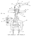
次に,図4及び図5において,導管27は,概略的に50で示す弁に接続されている。弁50は,図5に示す複数の流体貯蔵リザーバ60に出入りする流体を誘導するように機能する。弁50を,概略的に電磁方向弁として示しているが,ノズル16への流体の流れの流出源を複数のリザーバ60の間で切り替える任意のタイプの弁機構を用いることができるものと解釈されるべきである。本実施形態では,分注システム10は,2つのリザーバ60a,60bを採用している。しかしながら,当業者であれば,3つ以上の流体貯蔵リザーバへの応用を理解できるであろう。なお,複数のリザーバは,流体製品の安定供給を提供するように機能するものであるということに留意すべきである。つまり,複数のリザーバを備えることは,1つのリザーバが流体製品を供給している間に,他のリザーバは,いつでも保守サービスを受けることができる,すなわち製品を補充されることができることを意味する。
4 and 5, the
上記の説明及び添付の図面から,ある状態では,弁50によって,リザーバ60aの出力からノズル16への流体経路が確立されることが分かる。同時に,弁50によって,接続ポート25と第2のリザーバ60bとの間の流体経路も確立される。リザーバ60aの流体製品が空になると,制御システム70は,弁50を第2の状態すなわち第2の位置に移行させ,これにより,流体リザーバ60bは,ノズル16に流体接続され,リザーバ60aは,接続ポート25に流体連通する。
From the above description and the accompanying drawings, it can be seen that in some situations, the
引き続き図5において,流体リザーバ60の各々は,略細長円筒状のキャニスタ61を有し得るが,適切な判断によって,任意の幾何学的構成を選択することができる。キャニスタ61は,容積Vを有する液密の内部領域を画成している。本実施形態では,個々のキャニスタ61のそれぞれは,同じ容積Vを有しているが,同様に,異なる容積を有するキャニスタを採用することもできる。例として,容積Vは,流体製品の100ミリリットルから,最大で数リットルまでの範囲とすることができる。しかしながら,さらに広い範囲の容積を有するキャニスタ61を用いることもできる。
Continuing with FIG. 5, each of the
各キャニスタ61は,ピストンヘッド63を有し得る。ピストンヘッド63は,キャニスタ61の内径と厳密に一致するような外径又は他の幾何学的構成を有して構成される。ピストンヘッド63の周囲に,例えばOリングのようなシール材65を受容するための溝64を形成することができる。ただし,一部の流体製品は,本質的に粘性を有する場合があり,これは,ピストンヘッド63とキャニスタの壁との間に用いられるOリング又はシール材の使用を必要としないということに留意すべきである。いずれの場合も,分注システム10の全体が,周囲空気にさらされないように密封されることは理解されるであろう。
Each
キャニスタ61は,出口66を有する。出口66は,キャニスタ61の一端に,好ましくは頂部に設けてもよい。管67を,出口66から弁50の個々のポートまで延在させることができる。当然のことながら,管67は,それらの個々の入口及び出口に対して,大気への暴露を防ぐように液密に接続されている。管67を接続する任意の方法を選択することができ,限定するものではないが,密封接続継手が含まれる。
The
引き続き図5において,リザーバ60すなわちキャニスタ61から流体製品を吐出させるために,個々のピストンヘッド63はそれぞれ,アクチュエータ80に接続されている。図5において,2つの異なるアクチュエータ80,すなわちキャニスタごとに1つのアクチュエータを示しているが,これは単に例示を目的とするものにすぎない。理想的には,分注システム10では,両方の(又はすべての)リザーバ60において同じタイプのアクチュエータ80を用いる。アクチュエータの例として,限定するものではないが,空気圧源及び真空源,機械ボールねじ,電気モータ,又はコイルバネが含まれる。しかしながら,ピストンヘッド63を変位させるために,他のタイプのアクチュエータを用いることもできる。
Continuing with FIG. 5, each
アクチュエータ80は,概して,第1と第2の方向にピストンを駆動することが可能である。すなわち,アクチュエータ80は,ピストンヘッド63を出口66の方向に押すためと,ピストンヘッド63を出口66から離れる方向に引くためと,その両方のために機能する。ピストンヘッド63を出口66の方向に駆動することで,キャニスタ61内の製品が加圧されることは,当業者であればすぐに理解できるであろう。従って,ピストンヘッド63を漸進的に前進させることで,その結果,流体製品が定量で分注されることになる。反対方向に作動させると,ピストンヘッド63は,逆に,真空を生じさせる。一実施形態では,アクチュエータ80で,ピストンヘッド63を出口66から離れる方向に動かすことを用いて,後述するように,キャニスタ61に製品を自動的に補給する。
再び図4を参照して,分注システム10は,該分注システム10の動作シーケンスを制御するための1つ以上の電子回路71を含む制御システム70を備える。電子回路71は,プリント回路基板上に搭載して,図示していない適切な封入体(enclosure)に収容することができる。電子回路71に通電するために,同じく図示していない電源装置を設けることができる。一実施形態では,制御システム70への電力は,分注システム10が設置される施設から供給される商用電力を含むことができる。あるいは,同じく図示していない1つ以上のバッテリの形態で,オンボード電源を設けることができる。
Referring again to FIG. 4, the dispensing
制御システム70の電子回路71は,分注システム10の動作に関連したデータを受信して処理するように設計されたデジタル電子回路72を含むことができる。具体的には,デジタル電子回路72は,電子認証キー及びオンボードセンサ90から入力信号を受信するように機能する。このような回路では,アナログ/デジタル変換器を利用することができる。一実施形態では,デジタル電子回路72は,プログラム可能であり得る1つ以上の論理プロセッサ73を備えることができる。よって,回路72は,さらに,電子データ記憶装置75又はメモリ75を含み得る。
The electronic circuit 71 of the
また,デジタル電子回路72は,例えば,弁50の操作,及び1つ以上の電気モータ82を含み得るアクチュエータ80の作動のような,分注システム10の動作を制御するために用いられる信号を出力するようにも機能する。したがって,出力信号は,低電圧DC信号及び/又はAC信号を含み得る。どのような構成であるかにかかわらず,分注システム10の動作を制御するために必要となり得る多様な回路が使用及び実装されることは,当業者であれば理解できるであろう。
The digital electronic circuit 72 also outputs signals that are used to control the operation of the dispensing
再び図5を参照して,各キャニスタ61における残りの流体製品の量を特定するために,リザーバ60内にセンサ90を組み込むことができる。使用されるセンサの種類として,リミットスイッチ,圧力センサ,エンコーダ,又は例えばホール効果センサのような非接触近接センサを含むことができる。しかしながら,他の種類のセンサを使用してもよいことは,当業者であれば理解できるであろう。リザーバ60に残存する流体の量を特定する際に,センサ90は,流体の有無を直接感知するように構成することができる。あるいは,センサ90は,ピストンヘッド63の位置を検出し,続いて,そのピストンヘッドの位置を,キャニスタ61に残存する製品の量に関連付けるように構成することができる。さらに別の実施形態では,センサは,アクチュエータ80の作動又は位置を検出することにより,残存する製品の量を検出することができる。これら及び他の方法は,本明細書に記載の実施形態の適用範囲に含まれるものと解釈されるべきである。
Referring again to FIG. 5, a
具体的な一実施形態では,さらに,据付設備14にもセンサ91を組み込むことができる。これらのセンサ91は,分注システム10のハンズフリー作動のためのモーション検出に用いられる。センサ91は,1つ以上のIR発光器及び検出器を含むことができる。ノズル16の下の特定の領域で一貫した作動が確保されるように,任意の形態で発光器−検出器のペアを配置することができる。
In a specific embodiment, the
再び図1〜図5を参照して,分注システム10の動作の一実施形態について以下で説明する。制御システム70の最初の起動時又はリセット時に,流体製品の分注を開始するためのデフォルトのリザーバ(説明の目的では,流体リザーバ60a)を,予め決定すなわちプログラムすることができる。分注システム10が,ユーザによってセンサ91を介して作動させられると,制御システム70は,センサ90aの出力を読み取ることにより,キャニスタ61a内に製品があるかどうか確かめるためにチェックする。流体製品が存在する場合は,制御システム70は,定量の流体製品を分注するためにピストンヘッド63を順方向に駆動するための信号を,アクチュエータ80aに出力する。流体製品が存在することをセンサ90aが示し続けている限り,制御システム70は,センサ91の作動のたびに,アクチュエータ80aを働かせる。センサ90aからの信号が,キャニスタ61が空であることを示している場合には,制御システム70は,弁50をその別の状態に移行させることにより,リザーバ60bからの流体製品の取り出しを開始させる。さらに,制御システム70は,メンテナンスが必要であることをサービス員に知らせるためにインジケータをオンにするための信号を出力する。一実施形態では,インジケータは,据付設備14上に配置されたインジケータライト94とすることができる。あるいは,インジケータは,自然界で聞こえるものとすることができる。さらに,インジケータは,サービス員が監視するネットワークに送信される無線信号とすることができる。さらには,分注システム10で保守サービスが必要であることを知らせる任意の方法を選択することができる。
With reference to FIGS. 1 to 5 again, an embodiment of the operation of the dispensing
補給サイクルでは,サービス員が,補給容器31からの接続継手37を,据付設備14の接続ポート25に装着することができる。制御システム70は,正しい補給ユニットが装着されていることを確認するために,質問器42で受信した信号をチェックする。制御システム70は,認証後,「空」を通知しているキャニスタのアクチュエータに信号を出力する。これにより,アクチュエータは,ピストンヘッドを出口66から離れる方向に引いて,真空を生じさせることで,キャニスタに補給する。
In the supply cycle, the service person can attach the connection joint 37 from the
次に図6を参照すると,分注システム10の別の実施形態を示している。本実施形態では,分注システム10は,製品を分注するためと,リザーバ60に補給するためと,その両方のためにノズル16を用いる。従って,据付設備14は,単一の導管27aを収容している。リザーバに補給する必要がある場合は,補給容器31の接続継手37をノズル16に接続する。質問器42によって,同様に,適切な補給容器31が使用されていることを確認する。本例では,適切なリザーバ60に,すなわち製品が空のリザーバに,流体経路が接続されるように,弁50を一旦切り替える必要があり得る。その後,制御システム70は,適切なアクチュエータ80で,真空を生じさせることにより,流体製品をリザーバ内に引き込む。補給サイクルが完了した後に,制御システム70は,弁50をその以前の状態に戻すように切り替えて,これにより,流体製品は,引き続き,他方のリザーバから分注できるようになる。
Referring now to FIG. 6, another embodiment of the dispensing
本実施形態では,接続継手37は,ブリードポート38を備えて構成されることができる。周囲空気にさらされていた流体製品がリザーバ60内に引き戻されることがないようにするため,放出周期(purge cycle)を,制御システム70にプログラムすることができる。放出周期では,制御システム70は,空気にさらされていたかもしれないノズル16にある流体製品を流出させるために,適切なアクチュエータ80を順方向に駆動することができる。従って,継手37がノズル16に接続されていれば,流体製品はブリードポート38を通って流れ出ることになる。その後,制御システム70は,アクチュエータを逆方向に自動的に働かせることで,補給容器31からの流体を空のリザーバに引き込む。補給プロセス中にブリードポート38を通した流体製品の漏れを防ぐために,接続継手37は,逆止弁39でもあり得る1つ以上の弁を含むように設計され得ることは,当業者であれば理解できるであろう。
In the present embodiment, the connection joint 37 can be configured with a bleed port 38. A purge cycle can be programmed into the
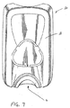
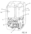
図7及び図8において,上述の実施形態は,カウンタ取付け型分注システムに関するものである。それらの実施形態では,据付設備とリザーバとは別々に設置されている。一方,別の実施形態が企図され,その場合,分注システム10の構成要素は,1つの封入体11内に収容される。具体的な一実施形態では,リザーバ60a,60b,弁50,制御システム70,及びノズル16はすべて,1つの封入体11内に収容される。図示のように,封入体11は,壁取付け型封入体とすることができる。封入体内に収容される複数のリザーバは,上述のものと同じように機能し得る。分注システム10への補給は,ノズル16を介して,あるいは図7及び図8に図示していない別途設けられた接続ポートを介して,実現することができる。
7 and 8, the above-described embodiment relates to a counter-mounted dispensing system. In these embodiments, the installation facility and the reservoir are installed separately. On the other hand, another embodiment is contemplated, in which case the components of the dispensing
マルチリザーバ分注システムの原理について,いくつかの実施形態において図示及び説明したが,かかる原理から逸脱することなく,本発明の構成及び詳細を変更できることは,当業者には容易に明らかであるに違いない。 Although the principles of the multi-reservoir dispensing system have been illustrated and described in some embodiments, it will be readily apparent to those skilled in the art that the configuration and details of the present invention may be changed without departing from such principles. Must.
Claims (26)
流体を貯蔵するための第1の流体リザーバと;
流体を貯蔵するための第2の流体リザーバと;
前記第1の流体リザーバと前記第2の流体リザーバからの流体を分注するため,及び,前記第1の流体リザーバと前記第2の流体リザーバに流体を補給するための据付設備と;
弁とを備え;
前記弁は,第1の状態にある間は,前記据付設備のノズルと前記第1の流体リザーバとの間に流体経路を確立し;かつ
前記弁は,第2の状態にある間は,前記ノズルと前記第2の流体リザーバとの間に流体経路を確立する,流体分注システム。 A fluid dispensing system:
A first fluid reservoir for storing fluid;
A second fluid reservoir for storing fluid;
An installation facility for dispensing fluid from the first fluid reservoir and the second fluid reservoir, and for replenishing fluid to the first fluid reservoir and the second fluid reservoir;
With a valve;
The valve establishes a fluid path between the nozzle of the installation equipment and the first fluid reservoir while in the first state; and while the valve is in the second state, the valve A fluid dispensing system that establishes a fluid path between a nozzle and the second fluid reservoir.
前記弁が前記第1の状態にある間は,前記ノズルと前記第2の流体リザーバとの間に流体経路は存在していない請求項1記載の流体分注システム。 While the valve is in the second state, there is no fluid path between the nozzle and the first fluid reservoir; and while the valve is in the first state, The fluid dispensing system of claim 1, wherein there is no fluid path between a nozzle and the second fluid reservoir.
流体を貯蔵するためのキャニスタと;
ピストンヘッドと;及び
前記ピストンヘッドを第1の方向と第2の方向に駆動するように構成されたアクチュエータとを有する請求項1記載の流体分注システム。 At least one of the first fluid reservoir or the second fluid reservoir is
A canister for storing fluid;
The fluid dispensing system of claim 1, comprising: a piston head; and an actuator configured to drive the piston head in a first direction and a second direction.
前記ピストンヘッドは,前記第2の方向に駆動されると,前記キャニスタ内に流体を引き込むために,前記キャニスタ内に真空を生じさせる請求項3記載の流体分注システム。 When the piston head is driven in the first direction, the piston head pressurizes fluid stored in the canister to dispense fluid from the canister; and the piston head is in the second direction 4. The fluid dispensing system of claim 3, wherein when driven, a vacuum is created in the canister to draw fluid into the canister.
前記弁は,前記第2の状態にある間は,前記補給接続ポートと前記第1の流体リザーバとの間に流体経路を確立する請求項5記載の流体分注システム。 The valve establishes a fluid path between the supply connection port and the second fluid reservoir while in the first state; and while the valve is in the second state, The fluid dispensing system of claim 5, wherein a fluid path is established between the replenishment connection port and the first fluid reservoir.
流体を貯蔵するためのキャニスタと;
前記キャニスタの壁との液密シールを形成しているピストンヘッドと;及び
前記ピストンヘッドを第1の方向と第2の方向に駆動するように構成されたアクチュエータとを備え,
前記ピストンヘッドは,前記第1の方向に駆動されると,前記キャニスタに貯蔵された流体を加圧し,前記第2の方向に駆動されると,前記キャニスタ内に真空を生じさせる,流体リザーバ。 A fluid reservoir for a fluid dispensing system comprising:
A canister for storing fluid;
A piston head forming a liquid tight seal with the wall of the canister; and an actuator configured to drive the piston head in a first direction and a second direction;
A fluid reservoir, wherein the piston head pressurizes fluid stored in the canister when driven in the first direction and creates a vacuum in the canister when driven in the second direction.
前記流体リザーバに補充される流体を貯蔵するための貯蔵領域と;及び
前記補給容器を前記流体分注システムに接続するための接続継手とを備え,前記接続継手は,
前記流体分注システムの質問器とのペアリングのための電子キーを有し,前記電子キーは,前記貯蔵領域に貯蔵されている流体の種類を,前記流体分注システムに通知する,補給容器。 A refill container for refilling a fluid reservoir of a fluid dispensing system comprising:
A storage area for storing fluid to be replenished in the fluid reservoir; and a connection joint for connecting the supply container to the fluid dispensing system, the connection joint comprising:
A replenishing container having an electronic key for pairing with an interrogator of the fluid dispensing system, the electronic key notifying the fluid dispensing system of the type of fluid stored in the storage area .
前記流体リザーバに補充される流体を貯蔵するための貯蔵領域と;及び
当該補給容器を前記流体分注システムに接続するための接続継手とを備え,前記接続継手は;
前記流体分注システム内の流体が放出されるときに通るブリードポートを有する,補給容器。 A refill container for refilling a fluid reservoir of a fluid dispensing system comprising:
A storage area for storing fluid to be replenished in the fluid reservoir; and a connection coupling for connecting the supply container to the fluid dispensing system, the connection coupling comprising:
A refill container having a bleed port through which fluid in the fluid dispensing system is discharged.
補給容器と前記流体分注システムとのペアリングを確認すること;
前記補給容器は,前記流体リザーバが受容すべき種類の流体を含むものであることを認証すること;及び
前記補給容器は,前記流体リザーバが受容すべき種類の流体を含むものであることを認証後,前記流体リザーバ内に真空を生じさせるために,前記流体リザーバのピストンヘッドを駆動するためのアクチュエータを作動させることであって,前記真空により,前記補給容器からの流体を前記流体リザーバに引き込むことを含む方法。 A method for refilling a fluid reservoir of a fluid dispensing system comprising:
Confirm pairing of the replenishment container and the fluid dispensing system;
Authenticating that the fluid reservoir contains the type of fluid to be received by the fluid reservoir; and after authenticating that the fluid reservoir contains the type of fluid to be received by the fluid reservoir, the fluid Actuating an actuator for driving a piston head of the fluid reservoir to create a vacuum in the reservoir, the vacuum including drawing fluid from the replenishing container into the fluid reservoir .
Applications Claiming Priority (3)
| Application Number | Priority Date | Filing Date | Title |
|---|---|---|---|
| US201361912052P | 2013-12-05 | 2013-12-05 | |
| US61/912,052 | 2013-12-05 | ||
| PCT/US2014/068837 WO2015085195A1 (en) | 2013-12-05 | 2014-12-05 | Product dispensing system |
Related Child Applications (1)
| Application Number | Title | Priority Date | Filing Date |
|---|---|---|---|
| JP2018079143A Division JP2018153644A (en) | 2013-12-05 | 2018-04-17 | Refill container for replenishing fluid reservoir of fluid dispensing system |
Publications (3)
| Publication Number | Publication Date |
|---|---|
| JP2017501779A true JP2017501779A (en) | 2017-01-19 |
| JP2017501779A5 JP2017501779A5 (en) | 2018-01-18 |
| JP6328243B2 JP6328243B2 (en) | 2018-05-23 |
Family
ID=53274172
Family Applications (2)
| Application Number | Title | Priority Date | Filing Date |
|---|---|---|---|
| JP2016536575A Expired - Fee Related JP6328243B2 (en) | 2013-12-05 | 2014-12-05 | Product dispensing system |
| JP2018079143A Pending JP2018153644A (en) | 2013-12-05 | 2018-04-17 | Refill container for replenishing fluid reservoir of fluid dispensing system |
Family Applications After (1)
| Application Number | Title | Priority Date | Filing Date |
|---|---|---|---|
| JP2018079143A Pending JP2018153644A (en) | 2013-12-05 | 2018-04-17 | Refill container for replenishing fluid reservoir of fluid dispensing system |
Country Status (6)
| Country | Link |
|---|---|
| US (2) | US9681780B2 (en) |
| EP (1) | EP3076841A1 (en) |
| JP (2) | JP6328243B2 (en) |
| AU (1) | AU2014360258B2 (en) |
| CA (2) | CA2932419C (en) |
| WO (1) | WO2015085195A1 (en) |
Families Citing this family (14)
| Publication number | Priority date | Publication date | Assignee | Title |
|---|---|---|---|---|
| EP3125734A1 (en) * | 2014-02-11 | 2017-02-08 | Gojo Industries, Inc. | Dispensing system with fluid level sensor |
| US9706883B2 (en) * | 2014-02-16 | 2017-07-18 | Mac Faucets, Llc | Fluid dispensing system |
| US10034584B2 (en) * | 2014-03-04 | 2018-07-31 | Gojo Industries, Inc. | Fluid dispenser and fluid refill system for fluid dispenser |
| GB2530290A (en) * | 2014-09-16 | 2016-03-23 | Justin Lovell | Liquid soap dispensing system |
| US11058261B2 (en) | 2015-07-15 | 2021-07-13 | Gojo Industries, Inc. | Bulk refill protection sensor for dispensing system |
| US10676340B2 (en) * | 2015-08-27 | 2020-06-09 | Deb Ip Limited | Filling hose |
| CA3010608A1 (en) | 2016-01-05 | 2017-07-13 | Gojo Industries, Inc. | Systems and methods for monitoring and controlling dispenser fluid refill |
| US10278549B1 (en) | 2016-10-31 | 2019-05-07 | Gpcp Ip Holdings Llc | Counter-mounted skincare product dispenser |
| US10961107B2 (en) * | 2017-03-14 | 2021-03-30 | Gojo Industries, Inc. | Refilling systems, refillable containers and method for refilling containers |
| DE102017119978B4 (en) | 2017-08-31 | 2020-01-09 | Hokwang Industries Co., Ltd. | MESA SOAP DISPENSER WITH A SOAP REFILL NOTIFICATION FUNCTION |
| US10247595B2 (en) | 2017-08-31 | 2019-04-02 | Hokwang Industries Co., Ltd. | Soap dispensing device having soap replenishing notification function |
| USD886240S1 (en) | 2018-04-26 | 2020-06-02 | Bradley Fixtures Corporation | Faucet and soap dispenser set |
| USD886245S1 (en) | 2018-04-26 | 2020-06-02 | Bradley Fixtures Corporation | Dispenser |
| WO2023158931A2 (en) * | 2022-02-17 | 2023-08-24 | Gojo Industries, Inc. | Reduced loss of prime foam at-a-distance dispenser systems |
Citations (4)
| Publication number | Priority date | Publication date | Assignee | Title |
|---|---|---|---|---|
| JPH0428313A (en) * | 1990-05-23 | 1992-01-30 | Inax Corp | Washstand equipped with soft soap feeder |
| JP2006149819A (en) * | 2004-11-30 | 2006-06-15 | Kawase Tetsuro | Washstand |
| JP2011152928A (en) * | 2010-01-27 | 2011-08-11 | Kyoritsu Seiyaku Kk | Liquid dispenser |
| US20140263421A1 (en) * | 2013-03-15 | 2014-09-18 | Gojo Industries, Inc. | Counter mount above-counter fill dispensing systems and refill units for same |
Family Cites Families (11)
| Publication number | Priority date | Publication date | Assignee | Title |
|---|---|---|---|---|
| US4467941A (en) * | 1982-09-30 | 1984-08-28 | Du Benjamin R | Apparatus and method for dispensing beverage syrup |
| JP3533814B2 (en) * | 1996-02-09 | 2004-05-31 | 東陶機器株式会社 | Water soap supply device |
| US6404837B1 (en) * | 1998-06-11 | 2002-06-11 | Ecolab, Inc. | Usage competent hand soap dispenser with data collection and display capabilities |
| US6557729B2 (en) | 2001-02-20 | 2003-05-06 | Sloan Valve Company | Soap dispensing system with single soap pump and two unpressurized soap containers |
| US6637466B2 (en) * | 2001-12-17 | 2003-10-28 | Lockheed Martin Corporation | Closed-loop filling system and method |
| JP3684212B2 (en) | 2002-06-05 | 2005-08-17 | 株式会社リコー | Volume reduction method for developer container, developer supply device, and image forming apparatus |
| JP2005152083A (en) * | 2003-11-21 | 2005-06-16 | Asahi Kasei Chemicals Corp | Feeding method for body washing agent |
| US7527174B2 (en) * | 2004-01-16 | 2009-05-05 | Masco Corporation Of Indiana | Stationary soap dispenser assembly |
| US8261780B2 (en) * | 2008-08-01 | 2012-09-11 | Delaware Capital Formation, Inc. | RFID controlled chemical porportioner and dispenser |
| US20130020351A1 (en) * | 2011-07-21 | 2013-01-24 | Gojo Industries, Inc. | Dispenser with optical keying system |
| EP3125734A1 (en) * | 2014-02-11 | 2017-02-08 | Gojo Industries, Inc. | Dispensing system with fluid level sensor |
-
2014
- 2014-12-05 US US15/102,025 patent/US9681780B2/en active Active
- 2014-12-05 JP JP2016536575A patent/JP6328243B2/en not_active Expired - Fee Related
- 2014-12-05 AU AU2014360258A patent/AU2014360258B2/en not_active Expired - Fee Related
- 2014-12-05 CA CA2932419A patent/CA2932419C/en not_active Expired - Fee Related
- 2014-12-05 CA CA2985636A patent/CA2985636A1/en not_active Abandoned
- 2014-12-05 EP EP14816070.8A patent/EP3076841A1/en not_active Withdrawn
- 2014-12-05 WO PCT/US2014/068837 patent/WO2015085195A1/en active Application Filing
-
2017
- 2017-06-19 US US15/627,387 patent/US20170280944A1/en not_active Abandoned
-
2018
- 2018-04-17 JP JP2018079143A patent/JP2018153644A/en active Pending
Patent Citations (4)
| Publication number | Priority date | Publication date | Assignee | Title |
|---|---|---|---|---|
| JPH0428313A (en) * | 1990-05-23 | 1992-01-30 | Inax Corp | Washstand equipped with soft soap feeder |
| JP2006149819A (en) * | 2004-11-30 | 2006-06-15 | Kawase Tetsuro | Washstand |
| JP2011152928A (en) * | 2010-01-27 | 2011-08-11 | Kyoritsu Seiyaku Kk | Liquid dispenser |
| US20140263421A1 (en) * | 2013-03-15 | 2014-09-18 | Gojo Industries, Inc. | Counter mount above-counter fill dispensing systems and refill units for same |
Also Published As
| Publication number | Publication date |
|---|---|
| CA2932419C (en) | 2018-01-02 |
| US20160309966A1 (en) | 2016-10-27 |
| WO2015085195A1 (en) | 2015-06-11 |
| US9681780B2 (en) | 2017-06-20 |
| AU2014360258A1 (en) | 2016-06-09 |
| US20170280944A1 (en) | 2017-10-05 |
| EP3076841A1 (en) | 2016-10-12 |
| JP6328243B2 (en) | 2018-05-23 |
| AU2014360258B2 (en) | 2018-07-05 |
| CA2985636A1 (en) | 2015-06-11 |
| CA2932419A1 (en) | 2015-06-11 |
| JP2018153644A (en) | 2018-10-04 |
Similar Documents
| Publication | Publication Date | Title |
|---|---|---|
| JP6328243B2 (en) | Product dispensing system | |
| US9730558B2 (en) | Product dispenser with pressure relief | |
| US7455197B2 (en) | Sink side touchless foam dispenser nozzle assembly | |
| US9648990B1 (en) | Venting system for dispenser reservoir | |
| US20080078780A1 (en) | Automatic dispenser | |
| CA2945378C (en) | Mini pump with compressible air inlet chamber for providing residual suck-back | |
| US20140124540A1 (en) | Under-counter mount foam dispensing systems with permanent air compressors and refill units for same | |
| EP1444049A1 (en) | Foam dispenser, housing and storage holder therefor | |
| MX2015004994A (en) | Dispensing system with the means for detecting liquid level and a collapsible container for such a system. | |
| US11659965B2 (en) | Bulk refill protection sensor for dispensing system | |
| JP6609846B2 (en) | Filling hose, method for filling a liquid dispenser, and system for filling a liquid dispenser | |
| JP5110638B2 (en) | Liquid supply device | |
| KR102194130B1 (en) | Bath apparatus | |
| EP3517454B1 (en) | Portable liquid dispenser | |
| US10149576B1 (en) | Automatic liquid soap supplying system | |
| US20060015994A1 (en) | Automatic dispenser | |
| US20230051196A1 (en) | Touch-free tabletop dispensers | |
| KR200384577Y1 (en) | Automatic hand sterilizer | |
| JP2022164191A (en) | Liquid jetting nozzle and liquid jetting device | |
| ITRM20100141A1 (en) | SANITIZER DEVICE FOR SANITARY VESSELS OF HYGIENIC SERVICES. | |
| ITPI20070029A1 (en) | ANTI-DISPERSAL DEVICE FOR AUTOMATIC DETERGENT DISPENSER |
Legal Events
| Date | Code | Title | Description |
|---|---|---|---|
| A521 | Request for written amendment filed |
Free format text: JAPANESE INTERMEDIATE CODE: A523 Effective date: 20171128 |
|
| A621 | Written request for application examination |
Free format text: JAPANESE INTERMEDIATE CODE: A621 Effective date: 20171128 |
|
| A871 | Explanation of circumstances concerning accelerated examination |
Free format text: JAPANESE INTERMEDIATE CODE: A871 Effective date: 20171128 |
|
| TRDD | Decision of grant or rejection written | ||
| A975 | Report on accelerated examination |
Free format text: JAPANESE INTERMEDIATE CODE: A971005 Effective date: 20180215 |
|
| A01 | Written decision to grant a patent or to grant a registration (utility model) |
Free format text: JAPANESE INTERMEDIATE CODE: A01 Effective date: 20180221 |
|
| A601 | Written request for extension of time |
Free format text: JAPANESE INTERMEDIATE CODE: A601 Effective date: 20180322 |
|
| A61 | First payment of annual fees (during grant procedure) |
Free format text: JAPANESE INTERMEDIATE CODE: A61 Effective date: 20180417 |
|
| R150 | Certificate of patent or registration of utility model |
Ref document number: 6328243 Country of ref document: JP Free format text: JAPANESE INTERMEDIATE CODE: R150 |
|
| R250 | Receipt of annual fees |
Free format text: JAPANESE INTERMEDIATE CODE: R250 |
|
| R250 | Receipt of annual fees |
Free format text: JAPANESE INTERMEDIATE CODE: R250 |
|
| LAPS | Cancellation because of no payment of annual fees |