JP2017501774A - Operation member and mechanism of drug delivery device, and drug delivery device - Google Patents
Operation member and mechanism of drug delivery device, and drug delivery device Download PDFInfo
- Publication number
- JP2017501774A JP2017501774A JP2016536158A JP2016536158A JP2017501774A JP 2017501774 A JP2017501774 A JP 2017501774A JP 2016536158 A JP2016536158 A JP 2016536158A JP 2016536158 A JP2016536158 A JP 2016536158A JP 2017501774 A JP2017501774 A JP 2017501774A
- Authority
- JP
- Japan
- Prior art keywords
- gaps
- gap
- operating member
- opening
- rim
- Prior art date
- Legal status (The legal status is an assumption and is not a legal conclusion. Google has not performed a legal analysis and makes no representation as to the accuracy of the status listed.)
- Granted
Links
- 230000007246 mechanism Effects 0.000 title claims description 46
- 238000012377 drug delivery Methods 0.000 title claims description 30
- 230000002093 peripheral effect Effects 0.000 claims description 4
- 238000013507 mapping Methods 0.000 claims description 3
- 238000002347 injection Methods 0.000 claims description 2
- 239000007924 injection Substances 0.000 claims description 2
- JUFFVKRROAPVBI-PVOYSMBESA-N chembl1210015 Chemical compound C([C@@H](C(=O)N[C@@H]([C@@H](C)CC)C(=O)N[C@@H](CCC(O)=O)C(=O)N[C@@H](CC=1C2=CC=CC=C2NC=1)C(=O)N[C@@H](CC(C)C)C(=O)N[C@@H](CCCCN)C(=O)N[C@@H](CC(=O)N[C@H]1[C@@H]([C@@H](O)[C@H](O[C@H]2[C@@H]([C@@H](O)[C@@H](O)[C@@H](CO[C@]3(O[C@@H](C[C@H](O)[C@H](O)CO)[C@H](NC(C)=O)[C@@H](O)C3)C(O)=O)O2)O)[C@@H](CO)O1)NC(C)=O)C(=O)NCC(=O)NCC(=O)N1[C@@H](CCC1)C(=O)N[C@@H](CO)C(=O)N[C@@H](CO)C(=O)NCC(=O)N[C@@H](C)C(=O)N1[C@@H](CCC1)C(=O)N1[C@@H](CCC1)C(=O)N1[C@@H](CCC1)C(=O)N[C@@H](CO)C(N)=O)NC(=O)[C@H](CC(C)C)NC(=O)[C@H](CCCNC(N)=N)NC(=O)[C@@H](NC(=O)[C@H](C)NC(=O)[C@H](CCC(O)=O)NC(=O)[C@H](CCC(O)=O)NC(=O)[C@H](CCC(O)=O)NC(=O)[C@H](CCSC)NC(=O)[C@H](CCC(N)=O)NC(=O)[C@H](CCCCN)NC(=O)[C@H](CO)NC(=O)[C@H](CC(C)C)NC(=O)[C@H](CC(O)=O)NC(=O)[C@H](CO)NC(=O)[C@@H](NC(=O)[C@H](CC=1C=CC=CC=1)NC(=O)[C@@H](NC(=O)CNC(=O)[C@H](CCC(O)=O)NC(=O)CNC(=O)[C@@H](N)CC=1NC=NC=1)[C@@H](C)O)[C@@H](C)O)C(C)C)C1=CC=CC=C1 JUFFVKRROAPVBI-PVOYSMBESA-N 0.000 description 83
- 108010011459 Exenatide Proteins 0.000 description 49
- 229960001519 exenatide Drugs 0.000 description 49
- 101000976075 Homo sapiens Insulin Proteins 0.000 description 22
- PBGKTOXHQIOBKM-FHFVDXKLSA-N insulin (human) Chemical compound C([C@@H](C(=O)N[C@@H](CC(C)C)C(=O)N[C@H]1CSSC[C@H]2C(=O)N[C@H](C(=O)N[C@@H](CO)C(=O)N[C@H](C(=O)N[C@H](C(N[C@@H](CO)C(=O)N[C@@H](CC(C)C)C(=O)N[C@@H](CC=3C=CC(O)=CC=3)C(=O)N[C@@H](CCC(N)=O)C(=O)N[C@@H](CC(C)C)C(=O)N[C@@H](CCC(O)=O)C(=O)N[C@@H](CC(N)=O)C(=O)N[C@@H](CC=3C=CC(O)=CC=3)C(=O)N[C@@H](CSSC[C@H](NC(=O)[C@H](C(C)C)NC(=O)[C@H](CC(C)C)NC(=O)[C@H](CC=3C=CC(O)=CC=3)NC(=O)[C@H](CC(C)C)NC(=O)[C@H](C)NC(=O)[C@H](CCC(O)=O)NC(=O)[C@H](C(C)C)NC(=O)[C@H](CC(C)C)NC(=O)[C@H](CC=3NC=NC=3)NC(=O)[C@H](CO)NC(=O)CNC1=O)C(=O)NCC(=O)N[C@@H](CCC(O)=O)C(=O)N[C@@H](CCCNC(N)=N)C(=O)NCC(=O)N[C@@H](CC=1C=CC=CC=1)C(=O)N[C@@H](CC=1C=CC=CC=1)C(=O)N[C@@H](CC=1C=CC(O)=CC=1)C(=O)N[C@@H]([C@@H](C)O)C(=O)N1[C@@H](CCC1)C(=O)N[C@@H](CCCCN)C(=O)N[C@@H]([C@@H](C)O)C(O)=O)C(=O)N[C@@H](CC(N)=O)C(O)=O)=O)CSSC[C@@H](C(N2)=O)NC(=O)[C@H](CCC(N)=O)NC(=O)[C@H](CCC(O)=O)NC(=O)[C@H](C(C)C)NC(=O)[C@@H](NC(=O)CN)[C@@H](C)CC)[C@@H](C)CC)[C@@H](C)O)NC(=O)[C@H](CCC(N)=O)NC(=O)[C@H](CC(N)=O)NC(=O)[C@@H](NC(=O)[C@@H](N)CC=1C=CC=CC=1)C(C)C)C1=CN=CN1 PBGKTOXHQIOBKM-FHFVDXKLSA-N 0.000 description 21
- 239000012634 fragment Substances 0.000 description 10
- 235000001014 amino acid Nutrition 0.000 description 9
- 150000001413 amino acids Chemical class 0.000 description 9
- 239000000427 antigen Substances 0.000 description 7
- 102000036639 antigens Human genes 0.000 description 7
- 108091007433 antigens Proteins 0.000 description 7
- 150000001875 compounds Chemical class 0.000 description 7
- 229940079593 drug Drugs 0.000 description 7
- 239000003814 drug Substances 0.000 description 7
- 150000003839 salts Chemical class 0.000 description 7
- 108090000765 processed proteins & peptides Proteins 0.000 description 5
- 108060003951 Immunoglobulin Proteins 0.000 description 4
- 102000018358 immunoglobulin Human genes 0.000 description 4
- 108010047041 Complementarity Determining Regions Proteins 0.000 description 3
- 208000002249 Diabetes Complications Diseases 0.000 description 3
- 210000003719 b-lymphocyte Anatomy 0.000 description 3
- 150000004676 glycans Chemical class 0.000 description 3
- 239000003055 low molecular weight heparin Substances 0.000 description 3
- 229940127215 low-molecular weight heparin Drugs 0.000 description 3
- -1 menotropin) Substances 0.000 description 3
- 229920001282 polysaccharide Polymers 0.000 description 3
- 239000005017 polysaccharide Substances 0.000 description 3
- 208000004476 Acute Coronary Syndrome Diseases 0.000 description 2
- 206010012689 Diabetic retinopathy Diseases 0.000 description 2
- 208000005189 Embolism Diseases 0.000 description 2
- 108010088406 Glucagon-Like Peptides Proteins 0.000 description 2
- 102000006771 Gonadotropins Human genes 0.000 description 2
- 108010086677 Gonadotropins Proteins 0.000 description 2
- HTTJABKRGRZYRN-UHFFFAOYSA-N Heparin Chemical compound OC1C(NC(=O)C)C(O)OC(COS(O)(=O)=O)C1OC1C(OS(O)(=O)=O)C(O)C(OC2C(C(OS(O)(=O)=O)C(OC3C(C(O)C(O)C(O3)C(O)=O)OS(O)(=O)=O)C(CO)O2)NS(O)(=O)=O)C(C(O)=O)O1 HTTJABKRGRZYRN-UHFFFAOYSA-N 0.000 description 2
- 102000002265 Human Growth Hormone Human genes 0.000 description 2
- 108010000521 Human Growth Hormone Proteins 0.000 description 2
- 239000000854 Human Growth Hormone Substances 0.000 description 2
- 208000001435 Thromboembolism Diseases 0.000 description 2
- 239000002253 acid Substances 0.000 description 2
- 150000001447 alkali salts Chemical class 0.000 description 2
- 125000000151 cysteine group Chemical group N[C@@H](CS)C(=O)* 0.000 description 2
- 108010015174 exendin 3 Proteins 0.000 description 2
- LMHMJYMCGJNXRS-IOPUOMRJSA-N exendin-3 Chemical compound C([C@@H](C(=O)N[C@@H]([C@@H](C)CC)C(=O)N[C@@H](CCC(O)=O)C(=O)N[C@@H](CC=1C2=CC=CC=C2NC=1)C(=O)N[C@@H](CC(C)C)C(=O)N[C@@H](CCCCN)C(=O)N[C@@H](CC(N)=O)C(=O)NCC(=O)NCC(=O)N1[C@@H](CCC1)C(=O)N[C@@H](CO)C(=O)N[C@@H](CO)C(=O)NCC(=O)N[C@@H](C)C(=O)N1[C@@H](CCC1)C(=O)N1[C@@H](CCC1)C(=O)N1[C@@H](CCC1)C(=O)N[C@@H](CO)C(N)=O)NC(=O)[C@H](CC(C)C)NC(=O)[C@H](CCCNC(N)=N)NC(=O)[C@@H](NC(=O)[C@H](C)NC(=O)[C@H](CCC(O)=O)NC(=O)[C@H](CCC(O)=O)NC(=O)[C@H](CCC(O)=O)NC(=O)[C@H](CCSC)NC(=O)[C@H](CCC(N)=O)NC(=O)[C@H](CCCCN)NC(=O)[C@H](CO)NC(=O)[C@H](CC(C)C)NC(=O)[C@H](CC(O)=O)NC(=O)[C@H](CO)NC(=O)[C@@H](NC(=O)[C@H](CC=1C=CC=CC=1)NC(=O)[C@@H](NC(=O)CNC(=O)[C@H](CC(O)=O)NC(=O)[C@H](CO)NC(=O)[C@@H](N)CC=1N=CNC=1)[C@H](C)O)[C@H](C)O)C(C)C)C1=CC=CC=C1 LMHMJYMCGJNXRS-IOPUOMRJSA-N 0.000 description 2
- 239000002622 gonadotropin Substances 0.000 description 2
- 229940088597 hormone Drugs 0.000 description 2
- 239000005556 hormone Substances 0.000 description 2
- 229940072221 immunoglobulins Drugs 0.000 description 2
- NOESYZHRGYRDHS-UHFFFAOYSA-N insulin Chemical class N1C(=O)C(NC(=O)C(CCC(N)=O)NC(=O)C(CCC(O)=O)NC(=O)C(C(C)C)NC(=O)C(NC(=O)CN)C(C)CC)CSSCC(C(NC(CO)C(=O)NC(CC(C)C)C(=O)NC(CC=2C=CC(O)=CC=2)C(=O)NC(CCC(N)=O)C(=O)NC(CC(C)C)C(=O)NC(CCC(O)=O)C(=O)NC(CC(N)=O)C(=O)NC(CC=2C=CC(O)=CC=2)C(=O)NC(CSSCC(NC(=O)C(C(C)C)NC(=O)C(CC(C)C)NC(=O)C(CC=2C=CC(O)=CC=2)NC(=O)C(CC(C)C)NC(=O)C(C)NC(=O)C(CCC(O)=O)NC(=O)C(C(C)C)NC(=O)C(CC(C)C)NC(=O)C(CC=2NC=NC=2)NC(=O)C(CO)NC(=O)CNC2=O)C(=O)NCC(=O)NC(CCC(O)=O)C(=O)NC(CCCNC(N)=N)C(=O)NCC(=O)NC(CC=3C=CC=CC=3)C(=O)NC(CC=3C=CC=CC=3)C(=O)NC(CC=3C=CC(O)=CC=3)C(=O)NC(C(C)O)C(=O)N3C(CCC3)C(=O)NC(CCCCN)C(=O)NC(C)C(O)=O)C(=O)NC(CC(N)=O)C(O)=O)=O)NC(=O)C(C(C)CC)NC(=O)C(CO)NC(=O)C(C(C)O)NC(=O)C1CSSCC2NC(=O)C(CC(C)C)NC(=O)C(NC(=O)C(CCC(N)=O)NC(=O)C(CC(N)=O)NC(=O)C(NC(=O)C(N)CC=1C=CC=CC=1)C(C)C)CC1=CN=CN1 NOESYZHRGYRDHS-UHFFFAOYSA-N 0.000 description 2
- 239000000203 mixture Substances 0.000 description 2
- 239000000178 monomer Substances 0.000 description 2
- 230000002265 prevention Effects 0.000 description 2
- 102000004196 processed proteins & peptides Human genes 0.000 description 2
- 239000011734 sodium Substances 0.000 description 2
- 239000012453 solvate Substances 0.000 description 2
- 229960004532 somatropin Drugs 0.000 description 2
- KIUKXJAPPMFGSW-DNGZLQJQSA-N (2S,3S,4S,5R,6R)-6-[(2S,3R,4R,5S,6R)-3-Acetamido-2-[(2S,3S,4R,5R,6R)-6-[(2R,3R,4R,5S,6R)-3-acetamido-2,5-dihydroxy-6-(hydroxymethyl)oxan-4-yl]oxy-2-carboxy-4,5-dihydroxyoxan-3-yl]oxy-5-hydroxy-6-(hydroxymethyl)oxan-4-yl]oxy-3,4,5-trihydroxyoxane-2-carboxylic acid Chemical compound CC(=O)N[C@H]1[C@H](O)O[C@H](CO)[C@@H](O)[C@@H]1O[C@H]1[C@H](O)[C@@H](O)[C@H](O[C@H]2[C@@H]([C@@H](O[C@H]3[C@@H]([C@@H](O)[C@H](O)[C@H](O3)C(O)=O)O)[C@H](O)[C@@H](CO)O2)NC(C)=O)[C@@H](C(O)=O)O1 KIUKXJAPPMFGSW-DNGZLQJQSA-N 0.000 description 1
- 125000004169 (C1-C6) alkyl group Chemical group 0.000 description 1
- 108091032973 (ribonucleotides)n+m Proteins 0.000 description 1
- 208000035285 Allergic Seasonal Rhinitis Diseases 0.000 description 1
- 206010002383 Angina Pectoris Diseases 0.000 description 1
- 201000001320 Atherosclerosis Diseases 0.000 description 1
- 108010017384 Blood Proteins Proteins 0.000 description 1
- 102000004506 Blood Proteins Human genes 0.000 description 1
- 108010037003 Buserelin Proteins 0.000 description 1
- 125000000882 C2-C6 alkenyl group Chemical group 0.000 description 1
- 125000000041 C6-C10 aryl group Chemical group 0.000 description 1
- 108010041986 DNA Vaccines Proteins 0.000 description 1
- 108010000437 Deamino Arginine Vasopressin Proteins 0.000 description 1
- 206010012655 Diabetic complications Diseases 0.000 description 1
- 108090000790 Enzymes Proteins 0.000 description 1
- 102000004190 Enzymes Human genes 0.000 description 1
- 102000003886 Glycoproteins Human genes 0.000 description 1
- 108090000288 Glycoproteins Proteins 0.000 description 1
- 102400000932 Gonadoliberin-1 Human genes 0.000 description 1
- 108010069236 Goserelin Proteins 0.000 description 1
- BLCLNMBMMGCOAS-URPVMXJPSA-N Goserelin Chemical compound C([C@@H](C(=O)N[C@H](COC(C)(C)C)C(=O)N[C@@H](CC(C)C)C(=O)N[C@@H](CCCN=C(N)N)C(=O)N1[C@@H](CCC1)C(=O)NNC(N)=O)NC(=O)[C@H](CO)NC(=O)[C@H](CC=1C2=CC=CC=C2NC=1)NC(=O)[C@H](CC=1NC=NC=1)NC(=O)[C@H]1NC(=O)CC1)C1=CC=C(O)C=C1 BLCLNMBMMGCOAS-URPVMXJPSA-N 0.000 description 1
- 101500026183 Homo sapiens Gonadoliberin-1 Proteins 0.000 description 1
- 108010024118 Hypothalamic Hormones Proteins 0.000 description 1
- 102000015611 Hypothalamic Hormones Human genes 0.000 description 1
- DGAQECJNVWCQMB-PUAWFVPOSA-M Ilexoside XXIX Chemical compound C[C@@H]1CC[C@@]2(CC[C@@]3(C(=CC[C@H]4[C@]3(CC[C@@H]5[C@@]4(CC[C@@H](C5(C)C)OS(=O)(=O)[O-])C)C)[C@@H]2[C@]1(C)O)C)C(=O)O[C@H]6[C@@H]([C@H]([C@@H]([C@H](O6)CO)O)O)O.[Na+] DGAQECJNVWCQMB-PUAWFVPOSA-M 0.000 description 1
- 108010021625 Immunoglobulin Fragments Proteins 0.000 description 1
- 102000008394 Immunoglobulin Fragments Human genes 0.000 description 1
- 102000006496 Immunoglobulin Heavy Chains Human genes 0.000 description 1
- 108010019476 Immunoglobulin Heavy Chains Proteins 0.000 description 1
- 102000013463 Immunoglobulin Light Chains Human genes 0.000 description 1
- 108010065825 Immunoglobulin Light Chains Proteins 0.000 description 1
- 206010061218 Inflammation Diseases 0.000 description 1
- 108010000817 Leuprolide Proteins 0.000 description 1
- XVVOERDUTLJJHN-UHFFFAOYSA-N Lixisenatide Chemical compound C=1NC2=CC=CC=C2C=1CC(C(=O)NC(CC(C)C)C(=O)NC(CCCCN)C(=O)NC(CC(N)=O)C(=O)NCC(=O)NCC(=O)N1C(CCC1)C(=O)NC(CO)C(=O)NC(CO)C(=O)NCC(=O)NC(C)C(=O)N1C(CCC1)C(=O)N1C(CCC1)C(=O)NC(CO)C(=O)NC(CCCCN)C(=O)NC(CCCCN)C(=O)NC(CCCCN)C(=O)NC(CCCCN)C(=O)NC(CCCCN)C(=O)NC(CCCCN)C(N)=O)NC(=O)C(CCC(O)=O)NC(=O)C(C(C)CC)NC(=O)C(NC(=O)C(CC(C)C)NC(=O)C(CCCNC(N)=N)NC(=O)C(NC(=O)C(C)NC(=O)C(CCC(O)=O)NC(=O)C(CCC(O)=O)NC(=O)C(CCC(O)=O)NC(=O)C(CCSC)NC(=O)C(CCC(N)=O)NC(=O)C(CCCCN)NC(=O)C(CO)NC(=O)C(CC(C)C)NC(=O)C(CC(O)=O)NC(=O)C(CO)NC(=O)C(NC(=O)C(CC=1C=CC=CC=1)NC(=O)C(NC(=O)CNC(=O)C(CCC(O)=O)NC(=O)CNC(=O)C(N)CC=1NC=NC=1)C(C)O)C(C)O)C(C)C)CC1=CC=CC=C1 XVVOERDUTLJJHN-UHFFFAOYSA-N 0.000 description 1
- 102000009151 Luteinizing Hormone Human genes 0.000 description 1
- 108010073521 Luteinizing Hormone Proteins 0.000 description 1
- 241000124008 Mammalia Species 0.000 description 1
- 108010021717 Nafarelin Proteins 0.000 description 1
- 206010028980 Neoplasm Diseases 0.000 description 1
- 108091034117 Oligonucleotide Proteins 0.000 description 1
- 108090000526 Papain Proteins 0.000 description 1
- 102000057297 Pepsin A Human genes 0.000 description 1
- 108090000284 Pepsin A Proteins 0.000 description 1
- 108010047386 Pituitary Hormones Proteins 0.000 description 1
- 102000006877 Pituitary Hormones Human genes 0.000 description 1
- ONIBWKKTOPOVIA-UHFFFAOYSA-N Proline Chemical group OC(=O)C1CCCN1 ONIBWKKTOPOVIA-UHFFFAOYSA-N 0.000 description 1
- 239000004365 Protease Substances 0.000 description 1
- 208000010378 Pulmonary Embolism Diseases 0.000 description 1
- 108010050144 Triptorelin Pamoate Proteins 0.000 description 1
- 239000003513 alkali Substances 0.000 description 1
- 125000000539 amino acid group Chemical group 0.000 description 1
- 239000005557 antagonist Substances 0.000 description 1
- 229960002719 buserelin Drugs 0.000 description 1
- CUWODFFVMXJOKD-UVLQAERKSA-N buserelin Chemical compound CCNC(=O)[C@@H]1CCCN1C(=O)[C@H](CCCN=C(N)N)NC(=O)[C@H](CC(C)C)NC(=O)[C@@H](COC(C)(C)C)NC(=O)[C@@H](NC(=O)[C@H](CO)NC(=O)[C@H](CC=1C2=CC=CC=C2NC=1)NC(=O)[C@H](CC=1NC=NC=1)NC(=O)[C@H]1NC(=O)CC1)CC1=CC=C(O)C=C1 CUWODFFVMXJOKD-UVLQAERKSA-N 0.000 description 1
- 201000011510 cancer Diseases 0.000 description 1
- 150000001720 carbohydrates Chemical class 0.000 description 1
- 235000014633 carbohydrates Nutrition 0.000 description 1
- 125000003178 carboxy group Chemical group [H]OC(*)=O 0.000 description 1
- 150000001768 cations Chemical class 0.000 description 1
- 230000000295 complement effect Effects 0.000 description 1
- 235000018417 cysteine Nutrition 0.000 description 1
- 230000000881 depressing effect Effects 0.000 description 1
- 229960004281 desmopressin Drugs 0.000 description 1
- NFLWUMRGJYTJIN-NXBWRCJVSA-N desmopressin Chemical compound C([C@H]1C(=O)N[C@H](C(N[C@@H](CC(N)=O)C(=O)N[C@@H](CSSCCC(=O)N[C@@H](CC=2C=CC(O)=CC=2)C(=O)N1)C(=O)N1[C@@H](CCC1)C(=O)N[C@@H](CCCNC(N)=N)C(=O)NCC(N)=O)=O)CCC(=O)N)C1=CC=CC=C1 NFLWUMRGJYTJIN-NXBWRCJVSA-N 0.000 description 1
- 206010012601 diabetes mellitus Diseases 0.000 description 1
- 230000029087 digestion Effects 0.000 description 1
- 239000000539 dimer Substances 0.000 description 1
- 229960000610 enoxaparin Drugs 0.000 description 1
- 229940088598 enzyme Drugs 0.000 description 1
- 229960001442 gonadorelin Drugs 0.000 description 1
- XLXSAKCOAKORKW-AQJXLSMYSA-N gonadorelin Chemical compound C([C@@H](C(=O)NCC(=O)N[C@@H](CC(C)C)C(=O)N[C@@H](CCCNC(N)=N)C(=O)N1[C@@H](CCC1)C(=O)NCC(N)=O)NC(=O)[C@H](CO)NC(=O)[C@H](CC=1C2=CC=CC=C2NC=1)NC(=O)[C@H](CC=1N=CNC=1)NC(=O)[C@H]1NC(=O)CC1)C1=CC=C(O)C=C1 XLXSAKCOAKORKW-AQJXLSMYSA-N 0.000 description 1
- 229960002913 goserelin Drugs 0.000 description 1
- 229960002897 heparin Drugs 0.000 description 1
- 229920000669 heparin Polymers 0.000 description 1
- 125000001072 heteroaryl group Chemical group 0.000 description 1
- 229920002674 hyaluronan Polymers 0.000 description 1
- 229960003160 hyaluronic acid Drugs 0.000 description 1
- 229910052739 hydrogen Inorganic materials 0.000 description 1
- 239000001257 hydrogen Substances 0.000 description 1
- 125000004435 hydrogen atom Chemical class [H]* 0.000 description 1
- 239000000960 hypophysis hormone Substances 0.000 description 1
- 229940043650 hypothalamic hormone Drugs 0.000 description 1
- 239000000601 hypothalamic hormone Substances 0.000 description 1
- 230000004054 inflammatory process Effects 0.000 description 1
- 239000004026 insulin derivative Substances 0.000 description 1
- 230000003993 interaction Effects 0.000 description 1
- 230000001788 irregular Effects 0.000 description 1
- GFIJNRVAKGFPGQ-LIJARHBVSA-N leuprolide Chemical compound CCNC(=O)[C@@H]1CCCN1C(=O)[C@H](CCCNC(N)=N)NC(=O)[C@H](CC(C)C)NC(=O)[C@@H](CC(C)C)NC(=O)[C@@H](NC(=O)[C@H](CO)NC(=O)[C@H](CC=1C2=CC=CC=C2NC=1)NC(=O)[C@H](CC=1N=CNC=1)NC(=O)[C@H]1NC(=O)CC1)CC1=CC=C(O)C=C1 GFIJNRVAKGFPGQ-LIJARHBVSA-N 0.000 description 1
- 229960004338 leuprorelin Drugs 0.000 description 1
- XVVOERDUTLJJHN-IAEQDCLQSA-N lixisenatide Chemical compound C([C@@H](C(=O)N[C@@H]([C@@H](C)CC)C(=O)N[C@@H](CCC(O)=O)C(=O)N[C@@H](CC=1C2=CC=CC=C2NC=1)C(=O)N[C@@H](CC(C)C)C(=O)N[C@@H](CCCCN)C(=O)N[C@@H](CC(N)=O)C(=O)NCC(=O)NCC(=O)N1[C@@H](CCC1)C(=O)N[C@@H](CO)C(=O)N[C@@H](CO)C(=O)NCC(=O)N[C@@H](C)C(=O)N1[C@@H](CCC1)C(=O)N1[C@@H](CCC1)C(=O)N[C@@H](CO)C(=O)N[C@@H](CCCCN)C(=O)N[C@@H](CCCCN)C(=O)N[C@@H](CCCCN)C(=O)N[C@@H](CCCCN)C(=O)N[C@@H](CCCCN)C(=O)N[C@@H](CCCCN)C(N)=O)NC(=O)[C@H](CC(C)C)NC(=O)[C@H](CCCNC(N)=N)NC(=O)[C@@H](NC(=O)[C@H](C)NC(=O)[C@H](CCC(O)=O)NC(=O)[C@H](CCC(O)=O)NC(=O)[C@H](CCC(O)=O)NC(=O)[C@H](CCSC)NC(=O)[C@H](CCC(N)=O)NC(=O)[C@H](CCCCN)NC(=O)[C@H](CO)NC(=O)[C@H](CC(C)C)NC(=O)[C@H](CC(O)=O)NC(=O)[C@H](CO)NC(=O)[C@@H](NC(=O)[C@H](CC=1C=CC=CC=1)NC(=O)[C@@H](NC(=O)CNC(=O)[C@H](CCC(O)=O)NC(=O)CNC(=O)[C@@H](N)CC=1N=CNC=1)[C@@H](C)O)[C@@H](C)O)C(C)C)C1=CC=CC=C1 XVVOERDUTLJJHN-IAEQDCLQSA-N 0.000 description 1
- 108010004367 lixisenatide Proteins 0.000 description 1
- 229960001093 lixisenatide Drugs 0.000 description 1
- 208000002780 macular degeneration Diseases 0.000 description 1
- 208000010125 myocardial infarction Diseases 0.000 description 1
- RWHUEXWOYVBUCI-ITQXDASVSA-N nafarelin Chemical compound C([C@@H](C(=O)N[C@H](CC=1C=C2C=CC=CC2=CC=1)C(=O)N[C@@H](CC(C)C)C(=O)N[C@@H](CCCN=C(N)N)C(=O)N1[C@@H](CCC1)C(=O)NCC(N)=O)NC(=O)[C@H](CO)NC(=O)[C@H](CC=1C2=CC=CC=C2NC=1)NC(=O)[C@H](CC=1NC=NC=1)NC(=O)[C@H]1NC(=O)CC1)C1=CC=C(O)C=C1 RWHUEXWOYVBUCI-ITQXDASVSA-N 0.000 description 1
- 229960002333 nafarelin Drugs 0.000 description 1
- 229940055729 papain Drugs 0.000 description 1
- 235000019834 papain Nutrition 0.000 description 1
- 229940111202 pepsin Drugs 0.000 description 1
- 239000008194 pharmaceutical composition Substances 0.000 description 1
- 229920001184 polypeptide Polymers 0.000 description 1
- 125000002924 primary amino group Chemical group [H]N([H])* 0.000 description 1
- 125000001500 prolyl group Chemical group [H]N1C([H])(C(=O)[*])C([H])([H])C([H])([H])C1([H])[H] 0.000 description 1
- 230000013777 protein digestion Effects 0.000 description 1
- 235000018102 proteins Nutrition 0.000 description 1
- 102000004169 proteins and genes Human genes 0.000 description 1
- 108090000623 proteins and genes Proteins 0.000 description 1
- 230000001105 regulatory effect Effects 0.000 description 1
- 230000000717 retained effect Effects 0.000 description 1
- 206010039073 rheumatoid arthritis Diseases 0.000 description 1
- 230000003248 secreting effect Effects 0.000 description 1
- 229910052708 sodium Inorganic materials 0.000 description 1
- 241000894007 species Species 0.000 description 1
- 229960004824 triptorelin Drugs 0.000 description 1
- VXKHXGOKWPXYNA-PGBVPBMZSA-N triptorelin Chemical compound C([C@@H](C(=O)N[C@H](CC=1C2=CC=CC=C2NC=1)C(=O)N[C@@H](CC(C)C)C(=O)N[C@@H](CCCNC(N)=N)C(=O)N1[C@@H](CCC1)C(=O)NCC(N)=O)NC(=O)[C@H](CO)NC(=O)[C@H](CC=1C2=CC=CC=C2NC=1)NC(=O)[C@H](CC=1N=CNC=1)NC(=O)[C@H]1NC(=O)CC1)C1=CC=C(O)C=C1 VXKHXGOKWPXYNA-PGBVPBMZSA-N 0.000 description 1
- 210000003462 vein Anatomy 0.000 description 1
Images


Classifications
-
- A—HUMAN NECESSITIES
- A61—MEDICAL OR VETERINARY SCIENCE; HYGIENE
- A61M—DEVICES FOR INTRODUCING MEDIA INTO, OR ONTO, THE BODY; DEVICES FOR TRANSDUCING BODY MEDIA OR FOR TAKING MEDIA FROM THE BODY; DEVICES FOR PRODUCING OR ENDING SLEEP OR STUPOR
- A61M5/00—Devices for bringing media into the body in a subcutaneous, intra-vascular or intramuscular way; Accessories therefor, e.g. filling or cleaning devices, arm-rests
- A61M5/178—Syringes
- A61M5/31—Details
- A61M5/315—Pistons; Piston-rods; Guiding, blocking or restricting the movement of the rod or piston; Appliances on the rod for facilitating dosing ; Dosing mechanisms
- A61M5/31533—Dosing mechanisms, i.e. setting a dose
- A61M5/31545—Setting modes for dosing
- A61M5/31548—Mechanically operated dose setting member
- A61M5/3155—Mechanically operated dose setting member by rotational movement of dose setting member, e.g. during setting or filling of a syringe
-
- A—HUMAN NECESSITIES
- A61—MEDICAL OR VETERINARY SCIENCE; HYGIENE
- A61M—DEVICES FOR INTRODUCING MEDIA INTO, OR ONTO, THE BODY; DEVICES FOR TRANSDUCING BODY MEDIA OR FOR TAKING MEDIA FROM THE BODY; DEVICES FOR PRODUCING OR ENDING SLEEP OR STUPOR
- A61M5/00—Devices for bringing media into the body in a subcutaneous, intra-vascular or intramuscular way; Accessories therefor, e.g. filling or cleaning devices, arm-rests
- A61M5/178—Syringes
- A61M5/24—Ampoule syringes, i.e. syringes with needle for use in combination with replaceable ampoules or carpules, e.g. automatic
-
- A—HUMAN NECESSITIES
- A61—MEDICAL OR VETERINARY SCIENCE; HYGIENE
- A61M—DEVICES FOR INTRODUCING MEDIA INTO, OR ONTO, THE BODY; DEVICES FOR TRANSDUCING BODY MEDIA OR FOR TAKING MEDIA FROM THE BODY; DEVICES FOR PRODUCING OR ENDING SLEEP OR STUPOR
- A61M5/00—Devices for bringing media into the body in a subcutaneous, intra-vascular or intramuscular way; Accessories therefor, e.g. filling or cleaning devices, arm-rests
- A61M5/178—Syringes
- A61M5/31—Details
- A61M5/315—Pistons; Piston-rods; Guiding, blocking or restricting the movement of the rod or piston; Appliances on the rod for facilitating dosing ; Dosing mechanisms
- A61M5/31533—Dosing mechanisms, i.e. setting a dose
- A61M5/31535—Means improving security or handling thereof, e.g. blocking means, means preventing insufficient dosing, means allowing correction of overset dose
- A61M5/31536—Blocking means to immobilize a selected dose, e.g. to administer equal doses
-
- A—HUMAN NECESSITIES
- A61—MEDICAL OR VETERINARY SCIENCE; HYGIENE
- A61M—DEVICES FOR INTRODUCING MEDIA INTO, OR ONTO, THE BODY; DEVICES FOR TRANSDUCING BODY MEDIA OR FOR TAKING MEDIA FROM THE BODY; DEVICES FOR PRODUCING OR ENDING SLEEP OR STUPOR
- A61M5/00—Devices for bringing media into the body in a subcutaneous, intra-vascular or intramuscular way; Accessories therefor, e.g. filling or cleaning devices, arm-rests
- A61M5/178—Syringes
- A61M5/31—Details
- A61M5/315—Pistons; Piston-rods; Guiding, blocking or restricting the movement of the rod or piston; Appliances on the rod for facilitating dosing ; Dosing mechanisms
- A61M5/31533—Dosing mechanisms, i.e. setting a dose
- A61M5/31545—Setting modes for dosing
- A61M5/31548—Mechanically operated dose setting member
- A61M5/3155—Mechanically operated dose setting member by rotational movement of dose setting member, e.g. during setting or filling of a syringe
- A61M5/31551—Mechanically operated dose setting member by rotational movement of dose setting member, e.g. during setting or filling of a syringe including axial movement of dose setting member
-
- A—HUMAN NECESSITIES
- A61—MEDICAL OR VETERINARY SCIENCE; HYGIENE
- A61M—DEVICES FOR INTRODUCING MEDIA INTO, OR ONTO, THE BODY; DEVICES FOR TRANSDUCING BODY MEDIA OR FOR TAKING MEDIA FROM THE BODY; DEVICES FOR PRODUCING OR ENDING SLEEP OR STUPOR
- A61M5/00—Devices for bringing media into the body in a subcutaneous, intra-vascular or intramuscular way; Accessories therefor, e.g. filling or cleaning devices, arm-rests
- A61M5/178—Syringes
- A61M5/24—Ampoule syringes, i.e. syringes with needle for use in combination with replaceable ampoules or carpules, e.g. automatic
- A61M2005/2485—Ampoule holder connected to rest of syringe
Abstract
操作部材(11)は、周辺部(18)を有する中心開口部(17)と、周辺部に配置され、かつ突出リム(21)によって取り囲まれた開口部の中に延びる、少なくとも1つの突出要素(20)とを有する。突出リムは、少なくとも1つの間隙(22)によって、周辺部に沿って中断される。複数の間隙が設けられる場合、これらの間隙は、間隙のパターンが、間隙の完全なパターンをそれ自体に写像するのに、開口部の中心軸のまわりに360°の整数倍とは異なる回転を可能にする対称形を含まないように配置される。操作部材は、間隙の位置と対応する位置に当接部を含む駆動部材と組み合わされる。The operating member (11) has at least one projecting element extending into a central opening (17) having a perimeter (18) and an opening disposed in the perimeter and surrounded by a projecting rim (21) (20) The protruding rim is interrupted along the periphery by at least one gap (22). If multiple gaps are provided, these gaps will rotate differently by an integer multiple of 360 ° around the central axis of the opening to map the full pattern of gaps to themselves. Arranged so as not to include a symmetric shape that allows. The operation member is combined with a drive member including a contact portion at a position corresponding to the position of the gap.
Description
本発明は、薬物送達デバイス用機構の操作部材に関し、このような機構を組み込む薬物送達デバイスに関する。 The present invention relates to an operating member of a mechanism for a drug delivery device and to a drug delivery device incorporating such a mechanism.
特許文献1には、用量ダイヤルグリップと、用量ダイヤルスリーブと、薬物送達のためにピストンロッドを前進させるように働く駆動スリーブとを含む、薬物送達デバイス用の駆動機構が開示されている。用量ダイヤルグリップは用量ダイヤルスリーブに、これらの構成要素間の相対的な動きを防止するように固定される。用量ダイヤル設定中、駆動スリーブは、用量ダイヤルグリップ、用量ダイヤルスリーブおよび駆動スリーブが同時に回されるように、用量ダイヤルスリーブに一時的に、回転可能に連結される。薬剤投薬中には、用量ダイヤルスリーブはもはや駆動スリーブに回転可能に連結されない。用量ダイヤルグリップと駆動スリーブの間の相対的な軸方向の動きは、用量ダイヤルグリップの突出部材が、駆動スリーブと用量ダイヤルグリップの間の相対回転が可能にされるように駆動スリーブの周辺の環状凹部と係合することによって防止される。用量ダイヤルグリップの突出部材と駆動スリーブの環状凹部との間の係合は、操作中維持される。 U.S. Patent No. 6,057,051 discloses a drive mechanism for a drug delivery device that includes a dose dial grip, a dose dial sleeve, and a drive sleeve that serves to advance the piston rod for drug delivery. The dose dial grip is secured to the dose dial sleeve to prevent relative movement between these components. During dose dial setting, the drive sleeve is temporarily rotatably coupled to the dose dial sleeve such that the dose dial grip, dose dial sleeve and drive sleeve are rotated simultaneously. During drug dispensing, the dose dial sleeve is no longer rotatably connected to the drive sleeve. The relative axial movement between the dose dial grip and the drive sleeve allows the protruding member of the dose dial grip to be annular around the drive sleeve so that relative rotation between the drive sleeve and the dose dial grip is allowed. It is prevented by engaging the recess. Engagement between the protruding member of the dose dial grip and the annular recess of the drive sleeve is maintained during operation.
本発明の目的は、上述の機構を含む薬物送達デバイスの操作を改善することである。 An object of the present invention is to improve the operation of a drug delivery device comprising the mechanism described above.
この目的は、請求項1に記載の操作部材、請求項14に記載の機構、および請求項19に記載の薬物送達デバイスによって達成される。実施形態および変形形態は、独立請求項から派生する。
This object is achieved by an operating member according to claim 1, a mechanism according to
一態様によれば、本発明は、周辺部を有する中心開口部と、周辺部に配置され、かつ周辺部に配置された突出リムによって取り囲まれた開口部の中に延びる、少なくとも1つの突出要素とを備える操作部材に関する。突出リムは、少なくとも1つの間隙によって、周辺部に沿って中断される。複数の間隙が設けられる場合、間隙は、開口部を所定の場所に保ち、かつ間隙のそれぞれを間隙の1つに写像する(map)どの回転も360°の整数倍を含むように配置される。これは、間隙のパターンが、間隙の完全なパターンをそれ自体に写像するのに、開口部の中心軸のまわりに360°の整数倍とは異なる回転を可能にする対称形を含まないことを意味する。 According to one aspect, the present invention comprises at least one projecting element extending into an opening surrounded by a central opening having a periphery and a projecting rim disposed at the periphery and disposed at the periphery. It is related with an operation member provided with. The protruding rim is interrupted along the periphery by at least one gap. Where multiple gaps are provided, the gaps are arranged such that any rotation includes an integral multiple of 360 °, keeping the openings in place and mapping each of the gaps to one of the gaps. . This means that the gap pattern does not include a symmetric shape that allows a rotation different from an integral multiple of 360 ° around the central axis of the opening to map the complete pattern of the gap to itself. means.
操作部材の一実施形態では、少なくとも1つの突出要素は、少なくとも1つの間隙に対向して配置される。 In one embodiment of the operating member, the at least one projecting element is arranged opposite the at least one gap.
操作部材の別の実施形態では、少なくとも1つの別の突出要素および少なくとも1つの別の間隙が設けられ、突出要素のそれぞれは、間隙の1つに対向して配置される。 In another embodiment of the operating member, at least one further projecting element and at least one other gap are provided, each of the projecting elements being arranged opposite one of the gaps.
操作部材の別の実施形態では、開口部は本質的に円形であり、少なくとも1つの間隙は、30°未満の角度を形成する開口部の半径によって制限される。突出リムは特に、30
°未満の角度を形成する半径によってそれぞれの間隙が制限される少なくとも3つの間隙を含む。
In another embodiment of the operating member, the opening is essentially circular and the at least one gap is limited by the radius of the opening forming an angle of less than 30 °. The protruding rim is especially 30
It includes at least three gaps, each gap limited by a radius that forms an angle of less than 0 °.
操作部材の別の実施形態では、突出リムは少なくとも3つの間隙を含み、これらの間隙の任意の一対の間隔は、これらの間隙の別の任意の一対の間隔とは、その一対と別の一対とが同じでない限り異なる。 In another embodiment of the operating member, the protruding rim includes at least three gaps, and any pair of gaps in these gaps is different from any other pair of gaps in these gaps. Different unless and are the same.
操作部材の別の実施形態では、突出リムは4つ、5つ、ないし6つの間隙を含む。 In another embodiment of the operating member, the protruding rim includes 4, 5 or 6 gaps.
操作部材の別の実施形態では、開口部は本質的に円形であり、突出リムは開口部の半径上に、これらの半径の連続したものからなる別々の対が、30°から60°までの角度、50°から80°までの角度、80°から130°までの角度、120°から160°までの角度を形成するように配置された4つの間隙を含み、これらの角度は互いに異なる。 In another embodiment of the operating member, the opening is essentially circular and the protruding rim is on the radius of the opening and separate pairs of these radii in succession between 30 ° and 60 °. It includes four gaps arranged to form an angle, an angle of 50 ° to 80 °, an angle of 80 ° to 130 °, an angle of 120 ° to 160 °, and these angles are different from each other.
操作部材の別の実施形態では、突出要素と突出リムは、開口部の周辺部に対して別々の高さに配置される。 In another embodiment of the operating member, the projecting element and the projecting rim are arranged at different heights relative to the periphery of the opening.
操作部材の別の実施形態では、少なくとも1つの別の突出要素が設けられ、これらの突出要素は、開口部の周辺部に対して同じ高さに配置される。 In another embodiment of the operating member, at least one further projecting element is provided, these projecting elements being arranged at the same height relative to the periphery of the opening.
操作部材の別の実施形態は、使用者によって実行予定のダイヤル設定操作のために設けられる少なくとも1つのグリップをさらに含む。操作部材は、具体的には、たとえば特にダイヤルグリップを回すことによって機構を操作するために使用者がつかむダイヤルグリップである。操作部材は特に、用量設定操作中に使用される。 Another embodiment of the operating member further includes at least one grip provided for a dial setting operation to be performed by the user. Specifically, the operating member is a dial grip that a user grasps to operate the mechanism, for example, by turning the dial grip in particular. The operating member is used in particular during a dose setting operation.
操作部材の別の実施形態では、突出リムは、間隙によって、周辺部に沿って中断され、間隙は、間隙のそれぞれを間隙の1つに写像する操作部材の回転が360°の整数倍を含むように配置され、少なくとも1つの突出リムは、間隙の1つに対向して配置される。 In another embodiment of the operating member, the protruding rim is interrupted along the periphery by a gap, the gap comprising an integer multiple of 360 ° of the operating member mapping each of the gaps to one of the gaps. The at least one protruding rim is disposed opposite one of the gaps.
別の態様では、本発明は、このような操作部材を含む薬物送達デバイスの機構に関する。機構の駆動部材が環状凹部を備え、操作部材の突出要素がその環状凹部に係合する。 In another aspect, the present invention relates to a mechanism for a drug delivery device comprising such an operating member. The drive member of the mechanism includes an annular recess, and the protruding element of the operating member engages with the annular recess.
組立て中、駆動スリーブの端部は、組み立てやすくするために、駆動スリーブの環状凹部を越えた位置に突出部材が達するように用量ダイヤルグリップがさらに入ることを可能にされる。機構の操作中に駆動スリーブが用量ダイヤルグリップに対してこの位置に達した場合(誤使用により起こる可能性がある)、機構は適正に作動せず、さらには破損する可能性さえある。 During assembly, the end of the drive sleeve is allowed further entry of the dose dial grip so that the protruding member reaches beyond the annular recess of the drive sleeve for ease of assembly. If the drive sleeve reaches this position with respect to the dose dial grip during operation of the mechanism (which may occur due to misuse), the mechanism will not operate properly and may even break.
機構の一実施形態では、少なくとも2つの間隙が操作部材の突出リムに設けられ、当接部が駆動部材上で、その間隙に対応する位置に配置される。好ましくは、当接部は、操作部材と駆動部材が長手方向に互いに相対的に動くときに、間隙を滑り抜けるように寸法設定される。間隙のパターンおよび対応する当接部は、突出部材が駆動スリーブの環状凹部を越える位置に達することを、1回転する位置を除いて防止する。 In one embodiment of the mechanism, at least two gaps are provided in the protruding rim of the operating member, and the abutting portion is disposed on the drive member at a position corresponding to the gap. Preferably, the contact portion is dimensioned so as to slip through the gap when the operation member and the drive member move relative to each other in the longitudinal direction. The gap pattern and the corresponding abutment prevent the projecting member from reaching the position beyond the annular recess of the drive sleeve, except for one rotation position.
機構の別の実施形態では、突出リムが当接部に当接する状態で突出要素が環状凹部に係合するように、操作部材の突出要素および突出リムは、開口部の周辺部に対して別々の高さで配置され、駆動部材の環状凹部および当接部は別々の高さに配置される。 In another embodiment of the mechanism, the projecting element and the projecting rim of the operating member are separate from the periphery of the opening so that the projecting element engages the annular recess while the projecting rim abuts the abutment. The annular concave portion and the abutting portion of the driving member are arranged at different heights.
機構の別の実施形態では、間隙は、突出要素が環状凹部を越えて当接部に当接するように、当接部が突出リムに入ることを可能にする。 In another embodiment of the mechanism, the gap allows the abutment to enter the protruding rim so that the protruding element abuts the abutment beyond the annular recess.
機構の別の実施形態はピストンロッドを含み、駆動部材は、そのピストンロッドを前進させるように設けられる。 Another embodiment of the mechanism includes a piston rod, and the drive member is provided to advance the piston rod.
別の態様では、本発明は、このような機構を含む薬物送達デバイスに関する。 In another aspect, the invention relates to a drug delivery device comprising such a mechanism.
薬物送達デバイスは注射デバイスである。薬物送達デバイスは、ペン型デバイスであり、具体的にはペン型注射器である。このデバイスは、使い捨てデバイスであり、または交換可能なカートリッジ用のカートリッジホルダを含む再使用可能なデバイスである。デバイスは、可変の、好ましくは使用者が設定可能な、薬物の用量を投薬するように構成される。あるいは、デバイスは固定用量デバイスであり、具体的には、使用者が変えることができない薬物の用量を投薬するように構成されたデバイスである。薬物送達デバイスは、手動式に、具体的には非電気的に駆動されるデバイスである。 The drug delivery device is an injection device. The drug delivery device is a pen-type device, specifically a pen-type syringe. The device is a disposable device or a reusable device that includes a cartridge holder for a replaceable cartridge. The device is configured to dispense a variable, preferably user-configurable, dose of drug. Alternatively, the device is a fixed dose device, specifically a device configured to dispense a dose of a drug that cannot be changed by the user. The drug delivery device is a device that is driven manually, specifically non-electrically.
具体的には、薬物送達デバイスはWO2004/078239A1に記載されたデバイスであり、その内容は参照によって本明細書に組み入れる。 Specifically, the drug delivery device is the device described in WO2004 / 078239A1, the contents of which are hereby incorporated by reference.
機構の長手方向軸は対称軸である。機構の長手方向軸は機構の遠位端から機構の近位端まで延びる。長手方向軸は、操作部材の開口部の周辺部によって取り囲まれる中心軸である。「遠位端」という用語は、機構が薬物送達デバイスに組み込まれるときに薬物送達デバイスの投薬端の最も近くに配置予定である機構の端部を示す。「近位端」という用語は、デバイスの投薬端から最も遠くに配置予定である機構の端部を示す。機構の長手方向軸は、薬物送達デバイスの長手方向軸と平行である。薬物送達デバイスの長手方向軸は、デバイスの遠位端からデバイスの近位端まで延びる。 The longitudinal axis of the mechanism is the axis of symmetry. The longitudinal axis of the mechanism extends from the distal end of the mechanism to the proximal end of the mechanism. The longitudinal axis is a central axis that is surrounded by the periphery of the opening of the operating member. The term “distal end” refers to the end of the mechanism that is to be placed closest to the dispensing end of the drug delivery device when the mechanism is incorporated into the drug delivery device. The term “proximal end” refers to the end of the mechanism that is to be placed furthest from the dispensing end of the device. The longitudinal axis of the mechanism is parallel to the longitudinal axis of the drug delivery device. The longitudinal axis of the drug delivery device extends from the distal end of the device to the proximal end of the device.
本明細書で使用する用語「薬物」は、好ましくは少なくとも1つの薬学的に活性な化合物を含む医薬製剤を意味し、
ここで、一実施形態において、薬学的に活性な化合物は、最大1500Daまでの分子量を有し、および/または、ペプチド、タンパク質、多糖類、ワクチン、DNA、RNA、酵素、抗体もしくはそのフラグメント、ホルモンもしくはオリゴヌクレオチド、または上述の薬学的に活性な化合物の混合物であり、
ここで、さらなる実施形態において、薬学的に活性な化合物は、糖尿病、または糖尿病性網膜症などの糖尿病関連の合併症、深部静脈血栓塞栓症または肺血栓塞栓症などの血栓塞栓症、急性冠症候群(ACS)、狭心症、心筋梗塞、がん、黄斑変性症、炎症、枯草熱、アテローム性動脈硬化症および/または関節リウマチの処置および/または予防に有用であり、
ここで、さらなる実施形態において、薬学的に活性な化合物は、糖尿病または糖尿病性網膜症などの糖尿病に関連する合併症の処置および/または予防のための少なくとも1つのペプチドを含み、
ここで、さらなる実施形態において、薬学的に活性な化合物は、少なくとも1つのヒトインスリンもしくはヒトインスリン類似体もしくは誘導体、グルカゴン様ペプチド(GLP−1)もしくはその類似体もしくは誘導体、またはエキセンジン−3もしくはエキセンジン−4もしくはエキセンジン−3もしくはエキセンジン−4の類似体もしくは誘導体を含む。
The term “drug” as used herein means a pharmaceutical formulation that preferably comprises at least one pharmaceutically active compound,
Here, in one embodiment, the pharmaceutically active compound has a molecular weight of up to 1500 Da and / or a peptide, protein, polysaccharide, vaccine, DNA, RNA, enzyme, antibody or fragment thereof, hormone Or an oligonucleotide, or a mixture of the above-mentioned pharmaceutically active compounds,
Here, in a further embodiment, the pharmaceutically active compound is diabetic or diabetes related complications such as diabetic retinopathy, thromboembolism such as deep vein thromboembolism or pulmonary thromboembolism, acute coronary syndrome (ACS), useful for the treatment and / or prevention of angina pectoris, myocardial infarction, cancer, macular degeneration, inflammation, hay fever, atherosclerosis and / or rheumatoid arthritis,
Here, in a further embodiment, the pharmaceutically active compound comprises at least one peptide for the treatment and / or prevention of diabetes-related complications such as diabetes or diabetic retinopathy,
Here, in a further embodiment, the pharmaceutically active compound is at least one human insulin or human insulin analogue or derivative, glucagon-like peptide (GLP-1) or analogue or derivative thereof, or exendin-3 or exendin -4 or exendin-3 or analogs or derivatives of exendin-4.
インスリン類似体は、たとえば、Gly(A21),Arg(B31),Arg(B32)ヒトインスリン;Lys(B3),Glu(B29)ヒトインスリン;Lys(B28),Pro(B29)ヒトインスリン;Asp(B28)ヒトインスリン;B28位におけるプロリンがAsp、Lys、Leu、Val、またはAlaで置き換えられており、B29位において、LysがProで置き換えられていてもよいヒトインスリン;Ala(B26)ヒトインスリン;Des(B28−B30)ヒトインスリン;Des(B27)ヒトインスリン、およびDes(B30)ヒトインスリンである。 Insulin analogues include, for example, Gly (A21), Arg (B31), Arg (B32) human insulin; Lys (B3), Glu (B29) human insulin; Lys (B28), Pro (B29) human insulin; Asp ( B28) human insulin; proline at position B28 is replaced with Asp, Lys, Leu, Val, or Ala, and at position B29, human insulin where Lys may be replaced with Pro; Ala (B26) human insulin; Des (B28-B30) human insulin; Des (B27) human insulin, and Des (B30) human insulin.
インスリン誘導体は、たとえば、B29−N−ミリストイル−des(B30)ヒトインスリン;B29−N−パルミトイル−des(B30)ヒトインスリン;B29−N−ミリストイルヒトインスリン;B29−N−パルミトイルヒトインスリン;B28−N−ミリストイルLysB28ProB29ヒトインスリン;B28−N−パルミトイル−LysB28ProB29ヒトインスリン;B30−N−ミリストイル−ThrB29LysB30ヒトインスリン;B30−N−パルミトイル−ThrB29LysB30ヒトインスリン;B29−N−(N−パルミトイル−γ−グルタミル)−des(B30)ヒトインスリン;B29−N−(N−リトコリル−γ−グルタミル)−des(B30)ヒトインスリン;B29−N−(ω−カルボキシヘプタデカノイル)−des(B30)ヒトインスリン、およびB29−N−(ω−カルボキシヘプタデカノイル)ヒトインスリンである。 Insulin derivatives include, for example, B29-N-myristoyl-des (B30) human insulin; B29-N-palmitoyl-des (B30) human insulin; B29-N-myristoyl human insulin; B29-N-palmitoyl human insulin; B28- N-myristoyl LysB28ProB29 human insulin; B28-N-palmitoyl-LysB28ProB29 human insulin; B30-N-myristoyl-ThrB29LysB30 human insulin; B30-N-palmitoyl-ThrB29LysB30 human insulin; B29-N- (N-palmitoyl) -Des (B30) human insulin; B29-N- (N-ritocryl-γ-glutamyl) -des (B30) human insulin; B29-N- (ω- Carboxymethyl hepta decanoyl) -des (B30) human insulin, and B29-N- (ω- carboxyheptadecanoyl) human insulin.
エキセンジン−4は、たとえば、H−His−Gly−Glu−Gly−Thr−Phe−Thr−Ser−Asp−Leu−Ser−Lys−Gln−Met−Glu−Glu−Glu−Ala−Val−Arg−Leu−Phe−Ile−Glu−Trp−Leu−Lys−Asn−Gly−Gly−Pro−Ser−Ser−Gly−Ala−Pro−Pro−Pro−Ser−NH2配列のペプチドであるエキセンジン−4(1−39)を意味する。 Exendin-4 is, for example, H-His-Gly-Glu-Gly-Thr-Phe-Thr-Ser-Asp-Leu-Ser-Lys-Gln-Met-Glu-Glu-Glu-Ala-Val-Arg-Leu Exendin-4 (1-39, which is a peptide of the sequence -Phe-Ile-Glu-Trp-Leu-Lys-Asn-Gly-Gly-Pro-Ser-Ser-Gly-Ala-Pro-Pro-Pro-Ser-NH2 ).
エキセンジン−4誘導体は、たとえば、以下のリストの化合物:
H−(Lys)4−desPro36,desPro37エキセンジン−4(1−39)−NH2、
H−(Lys)5−desPro36,desPro37エキセンジン−4(1−39)−NH2、
desPro36エキセンジン−4(1−39)、
desPro36[Asp28]エキセンジン−4(1−39)、
desPro36[IsoAsp28]エキセンジン−4(1−39)、
desPro36[Met(O)14,Asp28]エキセンジン−4(1−39)、
desPro36[Met(O)14,IsoAsp28]エキセンジン−(1−39)、
desPro36[Trp(O2)25,Asp28]エキセンジン−4(1−39)、
desPro36[Trp(O2)25,IsoAsp28]エキセンジン−4(1−39)、
desPro36[Met(O)14,Trp(O2)25,Asp28]エキセンジン−4(1−39)、
desPro36[Met(O)14Trp(O2)25,IsoAsp28]エキセンジン−4(1−39);または
desPro36[Asp28]エキセンジン−4(1−39)、
desPro36[IsoAsp28]エキセンジン−4(1−39)、
desPro36[Met(O)14,Asp28]エキセンジン−4(1−39)、
desPro36[Met(O)14,IsoAsp28]エキセンジン−(1−39)、
desPro36[Trp(O2)25,Asp28]エキセンジン−4(1−39)、
desPro36[Trp(O2)25,IsoAsp28]エキセンジン−4(1−39)、
desPro36[Met(O)14,Trp(O2)25,Asp28]エキセンジン−4(1−39)、
desPro36[Met(O)14,Trp(O2)25,IsoAsp28]エキセンジン−4(1−39)、
(ここで、基−Lys6−NH2が、エキセンジン−4誘導体のC−末端に結合していてもよい);
Exendin-4 derivatives are, for example, compounds of the following list:
H- (Lys) 4-desPro36, desPro37 exendin-4 (1-39) -NH2,
H- (Lys) 5-desPro36, desPro37 exendin-4 (1-39) -NH2,
desPro36 exendin-4 (1-39),
desPro36 [Asp28] exendin-4 (1-39),
desPro36 [IsoAsp28] exendin-4 (1-39),
desPro36 [Met (O) 14, Asp28] exendin-4 (1-39),
desPro36 [Met (O) 14, IsoAsp28] Exendin- (1-39),
desPro36 [Trp (O2) 25, Asp28] exendin-4 (1-39),
desPro36 [Trp (O2) 25, IsoAsp28] exendin-4 (1-39),
desPro36 [Met (O) 14, Trp (O2) 25, Asp28] exendin-4 (1-39),
desPro36 [Met (O) 14Trp (O2) 25, IsoAsp28] Exendin-4 (1-39); or desPro36 [Asp28] Exendin-4 (1-39),
desPro36 [IsoAsp28] exendin-4 (1-39),
desPro36 [Met (O) 14, Asp28] exendin-4 (1-39),
desPro36 [Met (O) 14, IsoAsp28] Exendin- (1-39),
desPro36 [Trp (O2) 25, Asp28] exendin-4 (1-39),
desPro36 [Trp (O2) 25, IsoAsp28] exendin-4 (1-39),
desPro36 [Met (O) 14, Trp (O2) 25, Asp28] exendin-4 (1-39),
desPro36 [Met (O) 14, Trp (O 2) 25, IsoAsp 28] Exendin-4 (1-39),
(Wherein the group -Lys6-NH2 may be attached to the C-terminus of the exendin-4 derivative);
または、以下の配列のエキセンジン−4誘導体:
desPro36エキセンジン−4(1−39)−Lys6−NH2(AVE0010)、
H−(Lys)6−desPro36[Asp28]エキセンジン−4(1−39)−Lys6−NH2、
desAsp28Pro36,Pro37,Pro38エキセンジン−4(1−39)−NH2、
H−(Lys)6−desPro36,Pro38[Asp28]エキセンジン−4(1−39)−NH2、
H−Asn−(Glu)5desPro36,Pro37,Pro38[Asp28]エキセンジン−4(1−39)−NH2、
desPro36,Pro37,Pro38[Asp28]エキセンジン−4(1−39)−(Lys)6−NH2、
H−(Lys)6−desPro36,Pro37,Pro38[Asp28]エキセンジン−4(1−39)−(Lys)6−NH2、
H−Asn−(Glu)5−desPro36,Pro37,Pro38[Asp28]エキセンジン−4(1−39)−(Lys)6−NH2、
H−(Lys)6−desPro36[Trp(O2)25,Asp28]エキセンジン−4(1−39)−Lys6−NH2、
H−desAsp28Pro36,Pro37,Pro38[Trp(O2)25]エキセンジン−4(1−39)−NH2、
H−(Lys)6−desPro36,Pro37,Pro38[Trp(O2)25,Asp28]エキセンジン−4(1−39)−NH2、
H−Asn−(Glu)5−desPro36,Pro37,Pro38[Trp(O2)25,Asp28]エキセンジン−4(1−39)−NH2、
desPro36,Pro37,Pro38[Trp(O2)25,Asp28]エキセンジン−4(1−39)−(Lys)6−NH2、
H−(Lys)6−desPro36,Pro37,Pro38[Trp(O2)25,Asp28]エキセンジン−4(1−39)−(Lys)6−NH2、
H−Asn−(Glu)5−desPro36,Pro37,Pro38[Trp(O2)25,Asp28]エキセンジン−4(1−39)−(Lys)6−NH2、
H−(Lys)6−desPro36[Met(O)14,Asp28]エキセンジン−4(1−39)−Lys6−NH2、
desMet(O)14,Asp28Pro36,Pro37,Pro38エキセンジン−4(1−39)−NH2、
H−(Lys)6−desPro36,Pro37,Pro38[Met(O)14,Asp28]エキセンジン−4(1−39)−NH2、
H−Asn−(Glu)5−desPro36,Pro37,Pro38[Met(O)14,Asp28]エキセンジン−4(1−39)−NH2;
desPro36,Pro37,Pro38[Met(O)14,Asp28]エキセンジン−4(1−39)−(Lys)6−NH2、
H−(Lys)6−desPro36,Pro37,Pro38[Met(O)14,Asp28]エキセンジン−4(1−39)−(Lys)6−NH2、
H−Asn−(Glu)5desPro36,Pro37,Pro38[Met(O)14,Asp28]エキセンジン−4(1−39)−(Lys)6−NH2、
H−Lys6−desPro36[Met(O)14,Trp(O2)25,Asp28]エキセンジン−4(1−39)−Lys6−NH2、
H−desAsp28,Pro36,Pro37,Pro38[Met(O)14,Trp(O2)25]エキセンジン−4(1−39)−NH2、
H−(Lys)6−desPro36,Pro37,Pro38[Met(O)14,Asp28]エキセンジン−4(1−39)−NH2、
H−Asn−(Glu)5−desPro36,Pro37,Pro38[Met(O)14,Trp(O2)25,Asp28]エキセンジン−4(1−39)−NH2、
desPro36,Pro37,Pro38[Met(O)14,Trp(O2)25,Asp28]エキセンジン−4(1−39)−(Lys)6−NH2、
H−(Lys)6−desPro36,Pro37,Pro38[Met(O)14,Trp(O2)25,Asp28]エキセンジン−4(S1−39)−(Lys)6−NH2、
H−Asn−(Glu)5−desPro36,Pro37,Pro38[Met(O)14,Trp(O2)25,Asp28]エキセンジン−4(1−39)−(Lys)6−NH2;
または前述のいずれか1つのエキセンジン−4誘導体の薬学的に許容される塩もしくは溶媒和化合物
から選択される。
Or an exendin-4 derivative of the following sequence:
desPro36 exendin-4 (1-39) -Lys6-NH2 (AVE0010),
H- (Lys) 6-desPro36 [Asp28] Exendin-4 (1-39) -Lys6-NH2,
desAsp28Pro36, Pro37, Pro38 exendin-4 (1-39) -NH2,
H- (Lys) 6-desPro36, Pro38 [Asp28] Exendin-4 (1-39) -NH2,
H-Asn- (Glu) 5desPro36, Pro37, Pro38 [Asp28] Exendin-4 (1-39) -NH2,
desPro36, Pro37, Pro38 [Asp28] Exendin-4 (1-39)-(Lys) 6-NH2,
H- (Lys) 6-desPro36, Pro37, Pro38 [Asp28] Exendin-4 (1-39)-(Lys) 6-NH2,
H-Asn- (Glu) 5-desPro36, Pro37, Pro38 [Asp28] Exendin-4 (1-39)-(Lys) 6-NH2,
H- (Lys) 6-desPro36 [Trp (O2) 25, Asp28] exendin-4 (1-39) -Lys6-NH2,
H-desAsp28Pro36, Pro37, Pro38 [Trp (O2) 25] exendin-4 (1-39) -NH2,
H- (Lys) 6-desPro36, Pro37, Pro38 [Trp (O2) 25, Asp28] exendin-4 (1-39) -NH2,
H-Asn- (Glu) 5-desPro36, Pro37, Pro38 [Trp (O2) 25, Asp28] exendin-4 (1-39) -NH2,
desPro36, Pro37, Pro38 [Trp (O2) 25, Asp28] exendin-4 (1-39)-(Lys) 6-NH2,
H- (Lys) 6-desPro36, Pro37, Pro38 [Trp (O2) 25, Asp28] exendin-4 (1-39)-(Lys) 6-NH2,
H-Asn- (Glu) 5-desPro36, Pro37, Pro38 [Trp (O2) 25, Asp28] exendin-4 (1-39)-(Lys) 6-NH2,
H- (Lys) 6-desPro36 [Met (O) 14, Asp28] exendin-4 (1-39) -Lys6-NH2,
desMet (O) 14, Asp28Pro36, Pro37, Pro38 exendin-4 (1-39) -NH2,
H- (Lys) 6-desPro36, Pro37, Pro38 [Met (O) 14, Asp28] exendin-4 (1-39) -NH2,
H-Asn- (Glu) 5-desPro36, Pro37, Pro38 [Met (O) 14, Asp28] exendin-4 (1-39) -NH2;
desPro36, Pro37, Pro38 [Met (O) 14, Asp28] Exendin-4 (1-39)-(Lys) 6-NH2,
H- (Lys) 6-desPro36, Pro37, Pro38 [Met (O) 14, Asp28] exendin-4 (1-39)-(Lys) 6-NH2,
H-Asn- (Glu) 5desPro36, Pro37, Pro38 [Met (O) 14, Asp28] Exendin-4 (1-39)-(Lys) 6-NH2,
H-Lys6-desPro36 [Met (O) 14, Trp (O2) 25, Asp28] Exendin-4 (1-39) -Lys6-NH2,
H-desAsp28, Pro36, Pro37, Pro38 [Met (O) 14, Trp (O2) 25] exendin-4 (1-39) -NH2,
H- (Lys) 6-desPro36, Pro37, Pro38 [Met (O) 14, Asp28] exendin-4 (1-39) -NH2,
H-Asn- (Glu) 5-desPro36, Pro37, Pro38 [Met (O) 14, Trp (O2) 25, Asp28] Exendin-4 (1-39) -NH2,
desPro36, Pro37, Pro38 [Met (O) 14, Trp (O2) 25, Asp28] Exendin-4 (1-39)-(Lys) 6-NH2,
H- (Lys) 6-desPro36, Pro37, Pro38 [Met (O) 14, Trp (O2) 25, Asp28] Exendin-4 (S1-39)-(Lys) 6-NH2,
H-Asn- (Glu) 5-desPro36, Pro37, Pro38 [Met (O) 14, Trp (O2) 25, Asp28] Exendin-4 (1-39)-(Lys) 6-NH2;
Or a pharmaceutically acceptable salt or solvate of any one of the aforementioned exendin-4 derivatives.
ホルモンは、たとえば、ゴナドトロピン(フォリトロピン、ルトロピン、コリオンゴナドトロピン、メノトロピン)、ソマトロピン(ソマトロピン)、デスモプレシン、テルリプレシン、ゴナドレリン、トリプトレリン、ロイプロレリン、ブセレリン、ナファレリン、ゴセレリンなどの、Rote Liste、2008年版、50章に列挙されている脳下垂体ホルモンまたは視床下部ホルモンまたは調節性活性ペプチドおよびそれらのアンタゴニストである。 The hormones include, for example, gonadotropin (folytropin, lutropin, corion gonadotropin, menotropin), somatropin (somatropin), desmopressin, telluripressin, gonadorelin, triptorelin, leuprorelin, buserelin, nafarelin, goserelin, etc., Rote Liste, 2008 Pituitary hormones or hypothalamic hormones or regulatory active peptides and antagonists thereof.
多糖類としては、たとえば、グルコサミノグリカン、ヒアルロン酸、ヘパリン、低分子量ヘパリン、もしくは超低分子量ヘパリン、またはそれらの誘導体、または上述の多糖類の硫酸化形態、たとえば、ポリ硫酸化形態、および/または、薬学的に許容されるそれらの塩がある。ポリ硫酸化低分子量ヘパリンの薬学的に許容される塩の例としては、エノキサパリンナトリウムがある。 Polysaccharides include, for example, glucosaminoglycan, hyaluronic acid, heparin, low molecular weight heparin, or ultra low molecular weight heparin, or derivatives thereof, or sulfated forms of the above-described polysaccharides, such as polysulfated forms, and Or a pharmaceutically acceptable salt thereof. An example of a pharmaceutically acceptable salt of polysulfated low molecular weight heparin is sodium enoxaparin.
抗体は、基本構造を共有する免疫グロブリンとしても知られている球状血漿タンパク質(約150kDa)である。これらは、アミノ酸残基に付加された糖鎖を有するので、糖タンパク質である。各抗体の基本的な機能単位は免疫グロブリン(Ig)単量体(1つのIg単位のみを含む)であり、分泌型抗体はまた、IgAなどの2つのIg単位を有する二量体、硬骨魚のIgMのような4つのIg単位を有する四量体、または哺乳動物のIgMのように5つのIg単位を有する五量体でもあり得る。 Antibodies are globular plasma proteins (about 150 kDa), also known as immunoglobulins that share a basic structure. These are glycoproteins because they have sugar chains attached to amino acid residues. The basic functional unit of each antibody is an immunoglobulin (Ig) monomer (including only one Ig unit), and the secretory antibody is also a dimer having two Ig units such as IgA, teleost It can also be a tetramer with 4 Ig units, such as IgM, or a pentamer with 5 Ig units, like mammalian IgM.
Ig単量体は、4つのポリペプチド鎖、すなわち、システイン残基間のジスルフィド結合によって結合された2つの同一の重鎖および2本の同一の軽鎖から構成される「Y」字型の分子である。それぞれの重鎖は約440アミノ酸長であり、それぞれの軽鎖は約220アミノ酸長である。重鎖および軽鎖はそれぞれ、これらの折り畳み構造を安定化させる鎖内ジスルフィド結合を含む。それぞれの鎖は、Igドメインと呼ばれる構造ドメインから構成される。これらのドメインは約70〜110個のアミノ酸を含み、そのサイズおよび機能に基づいて異なるカテゴリー(たとえば、可変すなわちV、および定常すなわちC)に分類される。これらは、2つのβシートが、保存されたシステインと他の荷電アミノ酸との間の相互作用によって一緒に保持される「サンドイッチ」形状を作り出す特徴的な免疫グロブリン折り畳み構造を有する。 An Ig monomer is a “Y” -shaped molecule composed of four polypeptide chains, two identical heavy chains and two identical light chains joined by a disulfide bond between cysteine residues. It is. Each heavy chain is about 440 amino acids long and each light chain is about 220 amino acids long. Each heavy and light chain contains intrachain disulfide bonds that stabilize these folded structures. Each chain is composed of structural domains called Ig domains. These domains contain about 70-110 amino acids and are classified into different categories (eg, variable or V, and constant or C) based on their size and function. They have a characteristic immunoglobulin fold that creates a “sandwich” shape in which two β-sheets are held together by the interaction between conserved cysteines and other charged amino acids.
α、δ、ε、γおよびμで表される5種類の哺乳類Ig重鎖が存在する。存在する重鎖の種類により抗体のアイソタイプが定義され、これらの鎖はそれぞれ、IgA、IgD、IgE、IgGおよびIgM抗体中に見出される。 There are five types of mammalian Ig heavy chains represented by α, δ, ε, γ and μ. The type of heavy chain present defines the isotype of the antibody, and these chains are found in IgA, IgD, IgE, IgG, and IgM antibodies, respectively.
異なる重鎖はサイズおよび組成が異なり、αおよびγは約450個のアミノ酸を含み、δは約500個のアミノ酸を含み、μおよびεは約550個のアミノ酸を有する。各重鎖は、2つの領域、すなわち定常領域(CH)と可変領域(VH)を有する。1つの種において、定常領域は、同じアイソタイプのすべての抗体で本質的に同一であるが、異なるアイソタイプの抗体では異なる。重鎖γ、α、およびδは、3つのタンデム型のIgドメインと、可撓性を加えるためのヒンジ領域とから構成される定常領域を有し、重鎖μおよびεは、4つの免疫グロブリン・ドメインから構成される定常領域を有する。重鎖の可変領域は、異なるB細胞によって産生された抗体では異なるが、単一B細胞またはB細胞クローンによって産生された抗体すべてについては同じである。各重鎖の可変領域は、約110アミノ酸長であり、単一のIgドメインから構成される。 Different heavy chains differ in size and composition, α and γ contain about 450 amino acids, δ contain about 500 amino acids, and μ and ε have about 550 amino acids. Each heavy chain has two regions: a constant region (C H ) and a variable region (V H ). In one species, the constant region is essentially the same for all antibodies of the same isotype, but different for antibodies of different isotypes. Heavy chains γ, α, and δ have a constant region composed of three tandem Ig domains and a hinge region to add flexibility, and heavy chains μ and ε are four immunoglobulins -It has a constant region composed of domains. The variable region of the heavy chain is different for antibodies produced by different B cells, but is the same for all antibodies produced by a single B cell or B cell clone. The variable region of each heavy chain is approximately 110 amino acids long and is composed of a single Ig domain.
哺乳類では、λおよびκで表される2種類の免疫グロブリン軽鎖がある。軽鎖は2つの連続するドメイン、すなわち1つの定常ドメイン(CL)および1つの可変ドメイン(VL)を有する。軽鎖のおおよその長さは、211〜217個のアミノ酸である。各抗体は、常に同一である2本の軽鎖を有し、哺乳類の各抗体につき、軽鎖κまたはλの1つのタイプのみが存在する。 In mammals, there are two types of immunoglobulin light chains, denoted λ and κ. The light chain has two consecutive domains, one constant domain (CL) and one variable domain (VL). The approximate length of the light chain is 211-217 amino acids. Each antibody has two light chains that are always identical, and there is only one type of light chain κ or λ for each mammalian antibody.
すべての抗体の一般的な構造は非常に類似しているが、所与の抗体の固有の特性は、上記で詳述したように、可変(V)領域によって決定される。より具体的には、各軽鎖(VL)について3つおよび重鎖(HV)に3つの可変ループが、抗原との結合、すなわちその抗原特異性に関与する。これらのループは、相補性決定領域(CDR)と呼ばれる。VHドメインおよびVLドメインの両方からのCDRが抗原結合部位に寄与するので、最終的な抗原特異性を決定するのは重鎖と軽鎖の組合せであり、どちらか単独ではない。 Although the general structure of all antibodies is very similar, the unique properties of a given antibody are determined by the variable (V) region, as detailed above. More specifically, three variable loops for each light chain (VL) and three variable loops in the heavy chain (HV) are involved in antigen binding, ie its antigen specificity. These loops are called complementarity determining regions (CDRs). Since CDRs from both the VH and VL domains contribute to the antigen binding site, it is the combination of heavy and light chains that determines the final antigen specificity, not either alone.
「抗体フラグメント」は、上記で定義した少なくとも1つの抗原結合フラグメントを含み、そのフラグメントが由来する完全抗体と本質的に同じ機能および特異性を示す。パパインによる限定的なタンパク質消化は、Igプロトタイプを3つのフラグメントに切断する。1つの完全なL鎖および約半分のH鎖をそれぞれが含む2つの同一のアミノ末端フラグメントが、抗原結合フラグメント(Fab)である。サイズが同等であるが、鎖間ジスルフィド結合を有する両方の重鎖の半分の位置でカルボキシル末端を含む第3のフラグメントは、結晶可能なフラグメント(Fc)である。Fcは、炭水化物、相補結合部位、およびFcR結合部位を含む。限定的なペプシン消化により、Fab片とH−H鎖間ジスルフィド結合を含むヒンジ領域の両方を含む単一のF(ab’)2フラグメントが得られる。F(ab’)2は、抗原結合に対して二価である。F(ab’)2のジスルフィド結合は、Fab’を得るために切断することができる。さらに、重鎖および軽鎖の可変領域は、縮合して単鎖可変フラグメント(scFv)を形成することもできる。 “Antibody fragments” comprise at least one antigen-binding fragment as defined above and exhibit essentially the same function and specificity as the complete antibody from which the fragment is derived. Limited protein digestion with papain cleaves the Ig prototype into three fragments. Two identical amino terminal fragments, each containing one complete light chain and about half the heavy chain, are antigen-binding fragments (Fabs). A third fragment that is equivalent in size but contains a carboxyl terminus at half the positions of both heavy chains with interchain disulfide bonds is a crystallizable fragment (Fc). Fc includes a carbohydrate, a complementary binding site, and an FcR binding site. Limited pepsin digestion yields a single F (ab ') 2 fragment containing both the Fab piece and the hinge region containing the H-H interchain disulfide bond. F (ab ') 2 is divalent for antigen binding. The disulfide bond of F (ab ') 2 can be cleaved to obtain Fab'. In addition, the variable regions of the heavy and light chains can be condensed to form a single chain variable fragment (scFv).
薬学的に許容される塩は、たとえば、酸付加塩および塩基性塩である。酸付加塩としては、たとえば、HClまたはHBr塩がある。塩基性塩は、たとえば、アルカリまたはアルカリ土類、たとえば、Na+、またはK+、またはCa2+から選択されるカチオン、または、アンモニウムイオンN+(R1)(R2)(R3)(R4)(式中、R1〜R4は互いに独立に:水素、場合により置換されたC1〜C6アルキル基、場合により置換されたC2〜C6アルケニル基、場合により置換されたC6〜C10アリール基、または場合により置換されたC6〜C10ヘテロアリール基を意味する)を有する塩である。薬学的に許容される塩のさらなる例は、「Remington’s Pharmaceutical Sciences」17版、Alfonso R.Gennaro(編)、Mark Publishing Company、Easton、Pa.、U.S.A.、1985およびEncyclopedia of Pharmaceutical Technologyに記載されている。 Pharmaceutically acceptable salts are, for example, acid addition salts and basic salts. Examples of acid addition salts include HCl or HBr salts. The basic salt is, for example, a cation selected from alkali or alkaline earth such as Na +, or K +, or Ca2 +, or ammonium ions N + (R1) (R2) (R3) (R4) (wherein R1 ~ R4 are independently of each other: hydrogen, optionally substituted C1-C6 alkyl group, optionally substituted C2-C6 alkenyl group, optionally substituted C6-C10 aryl group, or optionally substituted C6- Meaning a C10 heteroaryl group). Additional examples of pharmaceutically acceptable salts can be found in “Remington's Pharmaceutical Sciences” 17th edition, Alfonso R. et al. Gennaro (eds.), Mark Publishing Company, Easton, Pa. U. S. A. 1985, and Encyclopedia of Pharmaceutical Technology.
薬学的に許容される溶媒和物は、たとえば、水和物である。 A pharmaceutically acceptable solvate is, for example, a hydrate.
以下は、添付の図と併せた、操作部材の例および実施形態についての詳細な説明である。 The following is a detailed description of examples and embodiments of operating members in conjunction with the attached figures.
図1は操作部材の実施形態を、中心軸に沿った方向における上面図で示す。操作部材11は概して円筒形であり、中心開口部17を有する。外周縁は、操作部材11を使用者が回しやすくなるグリップ14を備える。操作部材11は、特に操作部材11が薬物送達デバイスの機構の構成要素として適用される場合に、投与予定である薬物の用量をダイヤル設定するのに使用される。中心開口部17は概して円筒形であり、上面図に開口部17を取り囲む円として表された周辺部18を有する。
FIG. 1 shows an embodiment of the operating member in a top view in a direction along the central axis. The operating
図1は、例示的にいくつかの円の半径19を示す。少なくとも1つの突出要素20が、開口部17の周辺部18に設けられる。図1に示された実施形態では、4つの突出要素20が設けられている。突出要素20は特に、機構の別の構成要素に係合するフックまたはクランプである。突出リム21が、周辺部18の主要部分を限定し、周辺部に沿って少なくとも1つの間隙22を含む。図1に示された実施形態では、4つの間隙22が設けられ、突出要素20は間隙22に対向して配置されている。駆動部材のような機構の別の構成要素が、所定の位置よりも遠くに押されることを防止するために、突出要素20の代わりに他の要素を間隙22に対向して配置することもできる。間隙22は特に、間隙22が比較的狭くなるように、30°未満の角度を形成する開口部17の半径19によって制限される。
FIG. 1 illustratively shows several circle radii 19. At least one projecting
間隙22の中心を通る連続する半径19は、間隙22のパターンが不規則かつ非対称になるように、好ましくはそれぞれ異なる角度を形成する。この結果、間隙22のパターンの回転対称性が完全に無くなり、したがって間隙のパターンは、開口部17が所定の場所に保たれたままで、操作部材11の中心軸のまわりを回転することによってそれ自体の上に写像することが、360°の整数倍で回転させることをもちろん除いて、できない。角度が異なることはまた、隣接する間隙22の間の間隔31が異なること意味する。図1に示された操作部材11についてのさらなる詳細は、個々の実施形態に関して提供されるが、本発明の開示を有効にすることには不可欠ではなく、また説明もされない。
The continuous radii 19 through the center of the gap 22 preferably form different angles so that the pattern of the gap 22 is irregular and asymmetric. As a result, the rotational symmetry of the pattern of the gap 22 is completely eliminated, and therefore the pattern of the gap itself is rotated by rotating around the central axis of the operating
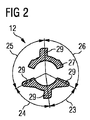
図2は、薬物送達デバイスの機構内の操作部材11と組み合わされるのに適している駆動部材12の細部である。駆動部材12は、薬物を容器から排出するのに使用される駆動機構のピストンロッドを前進させるように働く。駆動部材12は、特に駆動スリーブである。図12は、たとえば、概して円筒形の駆動スリーブである駆動部材12の近位端27の上面図を示す。少なくとも1つの当接部29が、駆動部材12の近位端27に設けられる。図2に示された実施形態では、4つの当接部29が設けられ、連続する当接部29の中心線が、それぞれ異なる角度23、24、25、26を形成する。これらの角度23、24、25、26は、操作部材11の突出リム21の間隙22の中心を通る、連続する半径19によって形成される角度と一致する。したがって、間隙22のパターンは、駆動部材12の当接部29のパターンと同じである。
FIG. 2 is a detail of a
実施形態では、最小の第1の角度23は30°から60°まで、より大きい第2の角度24は50°から80°まで、さらに大きい第3の角度25は80°から130°まで、最大の第4の角度26は120°から160°までである。典型的な角度には約55°の第1の角度23、約65°の第2の角度24、約115°の第3の角度25、約125°の第4の角度26が含まれ、4つの角度23、24、25、26が合計で360°になる。特定の範囲内の4つの異なる角度の別の例としては、30°、50°、130°および150°;30°、80°、110°および140°;40°、50°、110°および160°;50°、70°、80°および160°;60°、70°、80°および150°;または60°、80°、100°および120°がある。
In an embodiment, the minimum
図3は駆動部材12のその近位端27における断面図である。操作部材11の突出要素20を係合するために設けられている環状凹部28は、駆動部材12の、その近位端27に近い外面に形成される。当接部29は、環状凹部28の下のわずかに離れたところに配置される。
FIG. 3 is a cross-sectional view of the
図4は、操作部材11の突出要素20が駆動部材12の環状凹部28に係合するように組み立てられた操作部材11と駆動部材12の、図3に従った断面図である。図4の断面の位置は、1つの間隙22がその断面に含まれていることを示す図1に示され、図4の左側に示される関連した突出要素20は、駆動部材12が操作部材11の開口部17の中に、これらの構成要素の回転軸でもある中心軸30に沿って可能な限り押し込まれた場合に、駆動部材12の当接部29に当接する。操作部材11と駆動部材12の関連した軸方向の動きは、突出要素20を間隙22に対向して配置することによって抑止される。すでに述べたように、突出要素20は、間隙22に対向して配置される別の要素と置き換えることができるが、間隙22と対向する突出要素20の配置が好ましい。
FIG. 4 is a cross-sectional view according to FIG. 3 of the operating
当接部29のそれぞれが間隙22のうちの1つの位置に置かれている場合、突出リム21は、図4の右側に示されるように当接部29のいずれにも当接せず、したがって駆動部材12は、当接部29の少なくとも1つが突出リム21に対向して置かれている場合に可能であるよりも、操作部材11の奥に入れることができる。操作部材11が駆動部材12に対して完全に1回転する間に一度だけ占められるこの特定の位置においては、間隙22のパターンの対称性がないことにより、これらの構成要素には、したがって、突出要素20が機構の通常の使用に適切な位置を越えてわずかに離れた位置に達するまで、近づくことができる。この特性は、機構を組み立てやすくするのに望ましい。一方で、技法的な誤使用による機構の破損は、起きる可能性が従来の機構よりもはるかに小さい。その理由は、上述のように、中心軸30のまわりを構成要素が相対的に完全に1回転する間、操作部材11に対する駆動部材12の適切な位置が、1つの回転位置だけを除いて、突出リム21および当接部29によって固定されているからである。
When each of the
図5は、薬物送達デバイス1の断面図を示す。薬物送達デバイス1は、本体8内に駆動機構2を含み、場合により、投薬予定の薬物を含むカートリッジ5を収容するように構成されている、カートリッジホルダ4付きカートリッジサブアセンブリ3を含む。ピストン6は、カートリッジ5の近位端に保持される。取外し可能なキャップ7は、カートリッジサブアセンブリ3の遠位端を覆って解放可能に保持され、注射針ユニットと取り換えることができる。機構2は、ボタン9、クラッチ10、ダイヤルグリップ11、駆動部材12、ピストンロッド13、用量ダイヤル部材15および挿入物16を含み、この挿入物は、本体8に対する回転または長手方向の動きに対抗して固定され、特に本体8の一部である。カートリッジサブアセンブリ3は、本体8に固定される。本体8は、薬物送達デバイス1のハウジングである。挿入物16は、ダイヤル部材15と係合されるねじ付円形開口部と共に遠位端に設けられる。ピストンロッド13は、本体8のねじ付円形開口部32内で本体8とねじ係合される。ダイヤルグリップ11は、ダイヤル部材15に回転ロックおよび軸方向ロックされる。
FIG. 5 shows a cross-sectional view of the drug delivery device 1. The drug delivery device 1 includes a cartridge subassembly 3 with a cartridge holder 4 that includes a drive mechanism 2 within a
用量をダイヤル設定するために、使用者がダイヤルグリップ11を回すと、ダイヤル部材15、駆動部材12およびクラッチ10がダイヤルグリップ11と一緒に回転する。ダイヤル部材15および駆動部材12は、ピストンロッド13に対して近位方向に動かされる。所望の用量がダイヤル設定されると、使用者はボタン9を押し下げることによって、その用量を投薬することができる。これにより、クラッチ10はダイヤル部材15に対して軸方向に変位され、それによって、クラッチ10がダイヤル部材15から係合解除する。ボタン9を押し下げることによって、駆動部材12は軸方向の遠位方向に動かされる。これにより、ピストンロッド13は、本体8内のねじ付円形開口部32を通り抜けて回転し、それによってピストン6は、カートリッジ内で遠位方向に前進する。用量投薬の後、クラッチ10とダイヤル部材15は再係合される。
When the user turns the
1 薬物送達デバイス
2 駆動機構
3 カートリッジサブアセンブリ
4 カートリッジホルダ
5 カートリッジ
6 ピストン
7 キャップ
8 本体
9 ボタン
10 クラッチ
11 操作部材
12 駆動部材
13 ピストンロッド
14 グリップ
15 ダイヤル部材
16 挿入物
17 中心開口部
18 周辺部
19 半径
20 突出要素
21 突出リム
22 間隙
23 角度
24 角度
25 角度
26 角度
27 駆動部材の近位端
28 環状凹部
29 当接部
30 中心軸
31 間隔
32 ねじ付円形開口部
DESCRIPTION OF SYMBOLS 1 Drug delivery device 2 Drive mechanism 3 Cartridge subassembly 4 Cartridge holder 5 Cartridge 6 Piston 7
Claims (20)
周辺部(18)を有する中心開口部(17)と、
周辺部(18)に配置され、かつ開口部(17)の中に延びる、少なくとも1つの突出要素(20)と
を含み、
開口部(17)は、周辺部(18)に配置された突出リム(21)によって取り囲まれ、
突出リム(21)は、少なくとも1つの間隙(22)によって、周辺部(18)に沿って中断され、
開口部(17)を所定の場所に保ち、かつ間隙(22)のそれぞれを間隙(22)の1つに写像するどの回転も360°の整数倍を含むように、間隙(22)が1つだけ設けられる、または複数の間隙(22)が配置されることを特徴とする、前記操作部材。 An operating member of the mechanism of the drug delivery device,
A central opening (17) having a periphery (18);
At least one projecting element (20) disposed at the periphery (18) and extending into the opening (17);
The opening (17) is surrounded by a protruding rim (21) arranged at the periphery (18),
The protruding rim (21) is interrupted along the periphery (18) by at least one gap (22),
One gap (22) is kept so that the opening (17) is in place and any rotation that maps each of the gaps (22) to one of the gaps (22) includes an integral multiple of 360 °. Only, or a plurality of gaps (22) are arranged, said operating member.
突出リム(21)は開口部(17)の半径(19)上に、これらの半径(19)の連続したものからなる別々の対が、30°から60°までの角度(23)、50°から80°までの角度(24)、80°から130°までの角度(25)、120°から160°までの角度(26)を形成するように配置された4つの間隙(22)を含み、これらの角度(23、24、25、26)が互いに異なる、請求項7に記載の操作部材。 The opening (17) is essentially circular;
The projecting rim (21) is located on the radius (19) of the opening (17) on a separate pair of these radii (19) at an angle (23), 50 ° from 30 ° to 60 °. Including four gaps (22) arranged to form an angle (24) from 80 to 80, an angle (25) from 80 to 130 °, an angle (26) from 120 to 160 °, The operating member according to claim 7, wherein these angles (23, 24, 25, 26) are different from each other.
間隙(22)は、間隙(22)のそれぞれを間隙(22)の1つに写像する操作部材の回転が360°の整数倍を含むように配置される、請求項1〜11のいずれか1項に記載の操作部材。 The protruding rim (21) is interrupted along the periphery (18) by the gap (22),
The gap (22) is arranged such that the rotation of the operating member mapping each of the gaps (22) to one of the gaps (22) comprises an integral multiple of 360 °. The operation member according to item.
環状凹部(28)付きの駆動部材(12)をさらに含み、操作部材(11)の少なくとも1つの突出要素(20)がその環状凹部(28)に係合する、前記機構。 A mechanism of a drug delivery device comprising the operating member (11) according to any one of claims 1 to 13,
The mechanism further comprising a drive member (12) with an annular recess (28), wherein at least one protruding element (20) of the operating member (11) engages the annular recess (28).
駆動部材(12)上で、その間隙(22)に対応する位置に配置された当接部(29)と
をさらに含む、請求項14に記載の機構。 At least one further gap (22) provided in the protruding rim (21) of the operating member (11);
15. A mechanism according to claim 14, further comprising an abutment (29) disposed on the drive member (12) at a position corresponding to the gap (22).
Applications Claiming Priority (3)
| Application Number | Priority Date | Filing Date | Title |
|---|---|---|---|
| EP13196224.3 | 2013-12-09 | ||
| EP13196224 | 2013-12-09 | ||
| PCT/EP2014/076810 WO2015086481A1 (en) | 2013-12-09 | 2014-12-08 | Operation member and mechanism for a drug delivery device, and drug delivery device |
Publications (2)
| Publication Number | Publication Date |
|---|---|
| JP2017501774A true JP2017501774A (en) | 2017-01-19 |
| JP6488305B2 JP6488305B2 (en) | 2019-03-20 |
Family
ID=49753019
Family Applications (1)
| Application Number | Title | Priority Date | Filing Date |
|---|---|---|---|
| JP2016536158A Active JP6488305B2 (en) | 2013-12-09 | 2014-12-08 | Operation member and mechanism of drug delivery device, and drug delivery device |
Country Status (13)
| Country | Link |
|---|---|
| US (1) | US10342927B2 (en) |
| EP (1) | EP3079742B1 (en) |
| JP (1) | JP6488305B2 (en) |
| KR (1) | KR20160098288A (en) |
| CN (1) | CN105813673B (en) |
| AR (1) | AR098642A1 (en) |
| AU (1) | AU2014363806A1 (en) |
| HK (1) | HK1226015A1 (en) |
| IL (1) | IL245382A0 (en) |
| MX (1) | MX2016007485A (en) |
| RU (1) | RU2676513C1 (en) |
| TW (1) | TWI644696B (en) |
| WO (1) | WO2015086481A1 (en) |
Citations (1)
| Publication number | Priority date | Publication date | Assignee | Title |
|---|---|---|---|---|
| WO2011131777A1 (en) * | 2010-04-23 | 2011-10-27 | Sanofi-Aventis Deutschland Gmbh | Coded cartridge assembly, dose setting mechanism, drug delivery system and coded drug reservoir |
Family Cites Families (11)
| Publication number | Priority date | Publication date | Assignee | Title |
|---|---|---|---|---|
| US4003622A (en) | 1976-02-17 | 1977-01-18 | Harvey Hubbell Incorporated | Locking shroud for electrical connector |
| GB0304822D0 (en) * | 2003-03-03 | 2003-04-09 | Dca Internat Ltd | Improvements in and relating to a pen-type injector |
| EP1804865B1 (en) * | 2004-10-21 | 2009-09-30 | Novo Nordisk A/S | Dial-down mechanism for wind-up pen |
| WO2008016381A1 (en) | 2005-12-21 | 2008-02-07 | Algen & Klemer Llc | Dosage devices |
| EP2249905B1 (en) | 2008-02-07 | 2011-10-19 | Novo Nordisk A/S | Injection device having mode defining elements |
| US9186458B2 (en) | 2008-12-12 | 2015-11-17 | Shl Group Ab | Medicament delivery device |
| WO2010072229A1 (en) * | 2008-12-22 | 2010-07-01 | Tecpharma Licensing Ag | Dosing device for an injection device |
| JP5722992B2 (en) * | 2010-04-07 | 2015-05-27 | エス・ホー・エル・グループ・アクチボラゲットShl Group Ab | Drug delivery device |
| TWI544941B (en) * | 2010-10-06 | 2016-08-11 | 賽諾菲阿凡提斯德意志有限公司 | Drive mechanism for a drug delivery device and drug delivery device |
| US9358343B2 (en) | 2012-04-17 | 2016-06-07 | Carebay Europe Ltd | Medicament delivery device |
| EP2906272B1 (en) * | 2012-10-12 | 2018-12-05 | SHL Medical AG | Medicament delivery device |
-
2014
- 2014-12-05 TW TW103142279A patent/TWI644696B/en not_active IP Right Cessation
- 2014-12-05 AR ARP140104543A patent/AR098642A1/en unknown
- 2014-12-08 RU RU2016127576A patent/RU2676513C1/en not_active IP Right Cessation
- 2014-12-08 US US15/100,380 patent/US10342927B2/en active Active
- 2014-12-08 EP EP14809830.4A patent/EP3079742B1/en active Active
- 2014-12-08 AU AU2014363806A patent/AU2014363806A1/en not_active Abandoned
- 2014-12-08 JP JP2016536158A patent/JP6488305B2/en active Active
- 2014-12-08 WO PCT/EP2014/076810 patent/WO2015086481A1/en active Application Filing
- 2014-12-08 KR KR1020167017112A patent/KR20160098288A/en not_active Application Discontinuation
- 2014-12-08 MX MX2016007485A patent/MX2016007485A/en unknown
- 2014-12-08 CN CN201480066892.3A patent/CN105813673B/en active Active
-
2016
- 2016-05-02 IL IL245382A patent/IL245382A0/en unknown
- 2016-12-22 HK HK16114546A patent/HK1226015A1/en unknown
Patent Citations (1)
| Publication number | Priority date | Publication date | Assignee | Title |
|---|---|---|---|---|
| WO2011131777A1 (en) * | 2010-04-23 | 2011-10-27 | Sanofi-Aventis Deutschland Gmbh | Coded cartridge assembly, dose setting mechanism, drug delivery system and coded drug reservoir |
Also Published As
| Publication number | Publication date |
|---|---|
| WO2015086481A1 (en) | 2015-06-18 |
| EP3079742B1 (en) | 2024-02-28 |
| AU2014363806A1 (en) | 2016-06-23 |
| MX2016007485A (en) | 2017-04-27 |
| TWI644696B (en) | 2018-12-21 |
| KR20160098288A (en) | 2016-08-18 |
| US20160303325A1 (en) | 2016-10-20 |
| EP3079742A1 (en) | 2016-10-19 |
| JP6488305B2 (en) | 2019-03-20 |
| CN105813673B (en) | 2019-12-10 |
| EP3079742C0 (en) | 2024-02-28 |
| US10342927B2 (en) | 2019-07-09 |
| RU2676513C1 (en) | 2018-12-29 |
| CN105813673A (en) | 2016-07-27 |
| AR098642A1 (en) | 2016-06-01 |
| HK1226015A1 (en) | 2017-09-22 |
| TW201534366A (en) | 2015-09-16 |
| IL245382A0 (en) | 2016-06-30 |
Similar Documents
| Publication | Publication Date | Title |
|---|---|---|
| JP6339558B2 (en) | Pen syringe | |
| JP6577942B2 (en) | Injection device | |
| JP6073462B2 (en) | Cartridge holder and pen-type syringe | |
| JP6584582B2 (en) | Piston rod body support for drug delivery device, piston rod arrangement, and piston rod body | |
| JP6442283B2 (en) | Drug delivery device and cartridge holder for drug delivery device | |
| JP6386481B2 (en) | Assembly for a drug delivery device | |
| JP6235558B2 (en) | Drug delivery device assembly and drug delivery device | |
| JP2015511157A (en) | Spring assembly for drug delivery device | |
| JP2015521510A (en) | Drug container and drug delivery device | |
| JP6352316B2 (en) | Assembly for a drug delivery device | |
| JP6290087B2 (en) | Assembly of drug delivery device | |
| US10668222B2 (en) | Assembly for a drug delivery device and drug delivery device | |
| JP6496316B2 (en) | Drug delivery device housing | |
| JP6333859B2 (en) | Assembly for a drug delivery device | |
| JP6488305B2 (en) | Operation member and mechanism of drug delivery device, and drug delivery device | |
| JP6298056B2 (en) | Cap for drug delivery device and drug delivery device | |
| JP2016524974A (en) | Marking assembly | |
| JP6422969B2 (en) | Assembly for drug delivery device and drug delivery device | |
| JP2015536164A (en) | Counter system used in drug delivery devices | |
| JP6214549B2 (en) | Drive assembly for a drug delivery device and drug delivery device comprising the drive assembly | |
| JP2018513745A (en) | Drug delivery device and holding member for drug delivery device | |
| JP6602290B2 (en) | Mechanisms for drug delivery devices | |
| JP2016526991A (en) | Drug delivery device counting mechanism |
Legal Events
| Date | Code | Title | Description |
|---|---|---|---|
| A621 | Written request for application examination |
Free format text: JAPANESE INTERMEDIATE CODE: A621 Effective date: 20171127 |
|
| A977 | Report on retrieval |
Free format text: JAPANESE INTERMEDIATE CODE: A971007 Effective date: 20181005 |
|
| A131 | Notification of reasons for refusal |
Free format text: JAPANESE INTERMEDIATE CODE: A131 Effective date: 20181023 |
|
| A521 | Request for written amendment filed |
Free format text: JAPANESE INTERMEDIATE CODE: A523 Effective date: 20190122 |
|
| TRDD | Decision of grant or rejection written | ||
| A01 | Written decision to grant a patent or to grant a registration (utility model) |
Free format text: JAPANESE INTERMEDIATE CODE: A01 Effective date: 20190212 |
|
| A61 | First payment of annual fees (during grant procedure) |
Free format text: JAPANESE INTERMEDIATE CODE: A61 Effective date: 20190225 |
|
| R150 | Certificate of patent or registration of utility model |
Ref document number: 6488305 Country of ref document: JP Free format text: JAPANESE INTERMEDIATE CODE: R150 |
|
| R250 | Receipt of annual fees |
Free format text: JAPANESE INTERMEDIATE CODE: R250 |
|
| R250 | Receipt of annual fees |
Free format text: JAPANESE INTERMEDIATE CODE: R250 |
|
| R250 | Receipt of annual fees |
Free format text: JAPANESE INTERMEDIATE CODE: R250 |