JP2017501766A - Fluid moving device and method of use - Google Patents
Fluid moving device and method of use Download PDFInfo
- Publication number
- JP2017501766A JP2017501766A JP2016533117A JP2016533117A JP2017501766A JP 2017501766 A JP2017501766 A JP 2017501766A JP 2016533117 A JP2016533117 A JP 2016533117A JP 2016533117 A JP2016533117 A JP 2016533117A JP 2017501766 A JP2017501766 A JP 2017501766A
- Authority
- JP
- Japan
- Prior art keywords
- fluid
- source
- container
- air
- destination
- Prior art date
- Legal status (The legal status is an assumption and is not a legal conclusion. Google has not performed a legal analysis and makes no representation as to the accuracy of the status listed.)
- Pending
Links
Images


Classifications
-
- A—HUMAN NECESSITIES
- A61—MEDICAL OR VETERINARY SCIENCE; HYGIENE
- A61M—DEVICES FOR INTRODUCING MEDIA INTO, OR ONTO, THE BODY; DEVICES FOR TRANSDUCING BODY MEDIA OR FOR TAKING MEDIA FROM THE BODY; DEVICES FOR PRODUCING OR ENDING SLEEP OR STUPOR
- A61M5/00—Devices for bringing media into the body in a subcutaneous, intra-vascular or intramuscular way; Accessories therefor, e.g. filling or cleaning devices, arm-rests
- A61M5/178—Syringes
- A61M5/31—Details
-
- A—HUMAN NECESSITIES
- A61—MEDICAL OR VETERINARY SCIENCE; HYGIENE
- A61J—CONTAINERS SPECIALLY ADAPTED FOR MEDICAL OR PHARMACEUTICAL PURPOSES; DEVICES OR METHODS SPECIALLY ADAPTED FOR BRINGING PHARMACEUTICAL PRODUCTS INTO PARTICULAR PHYSICAL OR ADMINISTERING FORMS; DEVICES FOR ADMINISTERING FOOD OR MEDICINES ORALLY; BABY COMFORTERS; DEVICES FOR RECEIVING SPITTLE
- A61J1/00—Containers specially adapted for medical or pharmaceutical purposes
- A61J1/14—Details; Accessories therefor
- A61J1/20—Arrangements for transferring or mixing fluids, e.g. from vial to syringe
- A61J1/2096—Combination of a vial and a syringe for transferring or mixing their contents
-
- A—HUMAN NECESSITIES
- A61—MEDICAL OR VETERINARY SCIENCE; HYGIENE
- A61J—CONTAINERS SPECIALLY ADAPTED FOR MEDICAL OR PHARMACEUTICAL PURPOSES; DEVICES OR METHODS SPECIALLY ADAPTED FOR BRINGING PHARMACEUTICAL PRODUCTS INTO PARTICULAR PHYSICAL OR ADMINISTERING FORMS; DEVICES FOR ADMINISTERING FOOD OR MEDICINES ORALLY; BABY COMFORTERS; DEVICES FOR RECEIVING SPITTLE
- A61J1/00—Containers specially adapted for medical or pharmaceutical purposes
- A61J1/14—Details; Accessories therefor
- A61J1/20—Arrangements for transferring or mixing fluids, e.g. from vial to syringe
- A61J1/2003—Accessories used in combination with means for transfer or mixing of fluids, e.g. for activating fluid flow, separating fluids, filtering fluid or venting
- A61J1/202—Separating means
- A61J1/2037—Separating means having valve means
-
- A—HUMAN NECESSITIES
- A61—MEDICAL OR VETERINARY SCIENCE; HYGIENE
- A61J—CONTAINERS SPECIALLY ADAPTED FOR MEDICAL OR PHARMACEUTICAL PURPOSES; DEVICES OR METHODS SPECIALLY ADAPTED FOR BRINGING PHARMACEUTICAL PRODUCTS INTO PARTICULAR PHYSICAL OR ADMINISTERING FORMS; DEVICES FOR ADMINISTERING FOOD OR MEDICINES ORALLY; BABY COMFORTERS; DEVICES FOR RECEIVING SPITTLE
- A61J1/00—Containers specially adapted for medical or pharmaceutical purposes
- A61J1/14—Details; Accessories therefor
- A61J1/20—Arrangements for transferring or mixing fluids, e.g. from vial to syringe
- A61J1/2003—Accessories used in combination with means for transfer or mixing of fluids, e.g. for activating fluid flow, separating fluids, filtering fluid or venting
- A61J1/2048—Connecting means
- A61J1/2058—Connecting means having multiple connecting ports
-
- A—HUMAN NECESSITIES
- A61—MEDICAL OR VETERINARY SCIENCE; HYGIENE
- A61J—CONTAINERS SPECIALLY ADAPTED FOR MEDICAL OR PHARMACEUTICAL PURPOSES; DEVICES OR METHODS SPECIALLY ADAPTED FOR BRINGING PHARMACEUTICAL PRODUCTS INTO PARTICULAR PHYSICAL OR ADMINISTERING FORMS; DEVICES FOR ADMINISTERING FOOD OR MEDICINES ORALLY; BABY COMFORTERS; DEVICES FOR RECEIVING SPITTLE
- A61J1/00—Containers specially adapted for medical or pharmaceutical purposes
- A61J1/14—Details; Accessories therefor
- A61J1/20—Arrangements for transferring or mixing fluids, e.g. from vial to syringe
- A61J1/2003—Accessories used in combination with means for transfer or mixing of fluids, e.g. for activating fluid flow, separating fluids, filtering fluid or venting
- A61J1/2068—Venting means
- A61J1/2072—Venting means for internal venting
-
- A—HUMAN NECESSITIES
- A61—MEDICAL OR VETERINARY SCIENCE; HYGIENE
- A61J—CONTAINERS SPECIALLY ADAPTED FOR MEDICAL OR PHARMACEUTICAL PURPOSES; DEVICES OR METHODS SPECIALLY ADAPTED FOR BRINGING PHARMACEUTICAL PRODUCTS INTO PARTICULAR PHYSICAL OR ADMINISTERING FORMS; DEVICES FOR ADMINISTERING FOOD OR MEDICINES ORALLY; BABY COMFORTERS; DEVICES FOR RECEIVING SPITTLE
- A61J1/00—Containers specially adapted for medical or pharmaceutical purposes
- A61J1/05—Containers specially adapted for medical or pharmaceutical purposes for collecting, storing or administering blood, plasma or medical fluids ; Infusion or perfusion containers
- A61J1/10—Bag-type containers
-
- A—HUMAN NECESSITIES
- A61—MEDICAL OR VETERINARY SCIENCE; HYGIENE
- A61J—CONTAINERS SPECIALLY ADAPTED FOR MEDICAL OR PHARMACEUTICAL PURPOSES; DEVICES OR METHODS SPECIALLY ADAPTED FOR BRINGING PHARMACEUTICAL PRODUCTS INTO PARTICULAR PHYSICAL OR ADMINISTERING FORMS; DEVICES FOR ADMINISTERING FOOD OR MEDICINES ORALLY; BABY COMFORTERS; DEVICES FOR RECEIVING SPITTLE
- A61J1/00—Containers specially adapted for medical or pharmaceutical purposes
- A61J1/14—Details; Accessories therefor
- A61J1/1406—Septums, pierceable membranes
-
- A—HUMAN NECESSITIES
- A61—MEDICAL OR VETERINARY SCIENCE; HYGIENE
- A61J—CONTAINERS SPECIALLY ADAPTED FOR MEDICAL OR PHARMACEUTICAL PURPOSES; DEVICES OR METHODS SPECIALLY ADAPTED FOR BRINGING PHARMACEUTICAL PRODUCTS INTO PARTICULAR PHYSICAL OR ADMINISTERING FORMS; DEVICES FOR ADMINISTERING FOOD OR MEDICINES ORALLY; BABY COMFORTERS; DEVICES FOR RECEIVING SPITTLE
- A61J1/00—Containers specially adapted for medical or pharmaceutical purposes
- A61J1/14—Details; Accessories therefor
- A61J1/1475—Inlet or outlet ports
- A61J1/1481—Inlet or outlet ports with connection retaining means, e.g. thread or snap-fit
-
- A—HUMAN NECESSITIES
- A61—MEDICAL OR VETERINARY SCIENCE; HYGIENE
- A61J—CONTAINERS SPECIALLY ADAPTED FOR MEDICAL OR PHARMACEUTICAL PURPOSES; DEVICES OR METHODS SPECIALLY ADAPTED FOR BRINGING PHARMACEUTICAL PRODUCTS INTO PARTICULAR PHYSICAL OR ADMINISTERING FORMS; DEVICES FOR ADMINISTERING FOOD OR MEDICINES ORALLY; BABY COMFORTERS; DEVICES FOR RECEIVING SPITTLE
- A61J1/00—Containers specially adapted for medical or pharmaceutical purposes
- A61J1/14—Details; Accessories therefor
- A61J1/20—Arrangements for transferring or mixing fluids, e.g. from vial to syringe
- A61J1/2003—Accessories used in combination with means for transfer or mixing of fluids, e.g. for activating fluid flow, separating fluids, filtering fluid or venting
- A61J1/2006—Piercing means
- A61J1/201—Piercing means having one piercing end
-
- A—HUMAN NECESSITIES
- A61—MEDICAL OR VETERINARY SCIENCE; HYGIENE
- A61J—CONTAINERS SPECIALLY ADAPTED FOR MEDICAL OR PHARMACEUTICAL PURPOSES; DEVICES OR METHODS SPECIALLY ADAPTED FOR BRINGING PHARMACEUTICAL PRODUCTS INTO PARTICULAR PHYSICAL OR ADMINISTERING FORMS; DEVICES FOR ADMINISTERING FOOD OR MEDICINES ORALLY; BABY COMFORTERS; DEVICES FOR RECEIVING SPITTLE
- A61J1/00—Containers specially adapted for medical or pharmaceutical purposes
- A61J1/14—Details; Accessories therefor
- A61J1/20—Arrangements for transferring or mixing fluids, e.g. from vial to syringe
- A61J1/2089—Containers or vials which are to be joined to each other in order to mix their contents
-
- A—HUMAN NECESSITIES
- A61—MEDICAL OR VETERINARY SCIENCE; HYGIENE
- A61J—CONTAINERS SPECIALLY ADAPTED FOR MEDICAL OR PHARMACEUTICAL PURPOSES; DEVICES OR METHODS SPECIALLY ADAPTED FOR BRINGING PHARMACEUTICAL PRODUCTS INTO PARTICULAR PHYSICAL OR ADMINISTERING FORMS; DEVICES FOR ADMINISTERING FOOD OR MEDICINES ORALLY; BABY COMFORTERS; DEVICES FOR RECEIVING SPITTLE
- A61J2200/00—General characteristics or adaptations
- A61J2200/70—Device provided with specific sensor or indicating means
- A61J2200/76—Device provided with specific sensor or indicating means for fluid level
-
- A—HUMAN NECESSITIES
- A61—MEDICAL OR VETERINARY SCIENCE; HYGIENE
- A61M—DEVICES FOR INTRODUCING MEDIA INTO, OR ONTO, THE BODY; DEVICES FOR TRANSDUCING BODY MEDIA OR FOR TAKING MEDIA FROM THE BODY; DEVICES FOR PRODUCING OR ENDING SLEEP OR STUPOR
- A61M5/00—Devices for bringing media into the body in a subcutaneous, intra-vascular or intramuscular way; Accessories therefor, e.g. filling or cleaning devices, arm-rests
- A61M5/178—Syringes
- A61M5/31—Details
- A61M2005/3123—Details having air entrapping or venting means, e.g. purging channels in pistons
Landscapes
- Health & Medical Sciences (AREA)
- Life Sciences & Earth Sciences (AREA)
- Animal Behavior & Ethology (AREA)
- General Health & Medical Sciences (AREA)
- Public Health (AREA)
- Veterinary Medicine (AREA)
- Pharmacology & Pharmacy (AREA)
- Fluid Mechanics (AREA)
- Physics & Mathematics (AREA)
- Vascular Medicine (AREA)
- Engineering & Computer Science (AREA)
- Anesthesiology (AREA)
- Biomedical Technology (AREA)
- Heart & Thoracic Surgery (AREA)
- Hematology (AREA)
- Infusion, Injection, And Reservoir Apparatuses (AREA)
- Medical Preparation Storing Or Oral Administration Devices (AREA)
Abstract
本明細書に開示の実施形態は、流体を移動させるシステムおよび方法に関する。第1の流体容器と第2の流体容器との間に、流体通路が延伸可能である。第1の流体容器と第2の流体容器との間の流体通路に対しては、空気チャンバが流体連通可能である。通常の動作圧力においては、空気を空気チャンバに保持可能である。低圧状態(たとえば、異常による)においては、空気チャンバ中の空気が(たとえば、流体通路中の)検知箇所まで膨張し得る。検知箇所における空気の存在を空気センサが検出して、低圧状態の可能性を示すことができる。Embodiments disclosed herein relate to systems and methods for moving fluids. A fluid passage can extend between the first fluid container and the second fluid container. An air chamber is in fluid communication with the fluid passage between the first fluid container and the second fluid container. At normal operating pressure, air can be held in the air chamber. In low pressure conditions (eg, due to anomalies), air in the air chamber can expand to a detection location (eg, in the fluid passage). The presence of air at the detection location can be detected by the air sensor to indicate the possibility of a low pressure state.
Description
関連出願
本願は、2013年11月22日に出願された米国仮特許出願第61/907,995号「FLUID TRANSFER DEVICES AND METHODS OF USE」の利益を主張するものであり、そのすべての内容を本明細書に明示的に援用して、本明細書の一部を構成する。
This application claims the benefit of US Provisional Patent Application No. 61 / 907,995 “FLUID TRANSFER DEVICES AND METHODS OF USE” filed on November 22, 2013, the entire contents of which are hereby incorporated by reference. Which is expressly incorporated herein by reference.
参照による援用
米国特許出願第12/845,548号として2010年7月28日に出願され、2013年9月3日に特許された米国特許第8,522,832号(「'832特許」)「FLUID TRANSFER DEVICES AND METHODS OF USE」は、そのすべての内容を本明細書に援用して、すべての開示内容に関して本明細書の一部を構成する。
U.S. Patent Application No. 12 / 845,548, filed July 28, 2010, and issued on September 3, 2013, U.S. Pat.No. 8,522,832 (`` '832 patent'')"OFUSE" is hereby incorporated by reference in its entirety and forms part of this specification with respect to all disclosure content.
国際出願第PCT/US2012/071493号として2012年12月21日に出願され、2013年6月27日に公開された国際公開第WO2013/096911号(「'911公開」)「FLUID TRANSFER DEVICES AND METHODS OF USE」は、そのすべての内容を本明細書に援用して、すべての開示内容に関して本明細書の一部を構成する。 International Application No.PCT / US2012 / 071493, filed on December 21, 2012 and published on June 27, 2013, International Publication No.WO2013 / 096911 (“'911 Publication”) "OF USE" is hereby incorporated by reference in its entirety and forms part of this specification with respect to all disclosure content.
「'832特許」または「'911公開」に図示および/または記載されている任意の構成要素、構造、材料、ステップ、方法、またはシステムは、本明細書に図示および/または記載している任意の構成要素、構造、材料、ステップ、方法、またはシステムとの併用または代用が可能である。 Any component, structure, material, step, method, or system illustrated and / or described in the “'832 Patent” or “' 911 Publication” is optional and shown and / or described herein. Can be used or substituted with any component, structure, material, step, method, or system.
本開示のいくつかの実施形態は、流体を移動させる装置および方法に関し、より詳細には、医療用流体を第1の流体容器から第2の流体容器に移動させる装置および方法に関する。 Some embodiments of the present disclosure relate to an apparatus and method for moving fluid, and more particularly to an apparatus and method for moving medical fluid from a first fluid container to a second fluid container.
いくつかの状況においては、1つまたは複数の流体の容器間での移動が望ましいことがある。医療分野においては、医療用(たとえば、医薬)流体の正確な量での分注が望ましいことがある。いくつかの場合、潜在的に危険な流体(たとえば、化学療法剤または免疫抑制剤)の分注が望ましいことがある。いくつかの流体分注システムには、高コスト、低効率、労力の集中、および過剰な流体または蒸気の漏出等、さまざまな障害がある。いくつかの流体分注システムは、たとえば流体に伴う空気の移動によって、精度が不十分となり得る。いくつかの自動流体分注システムは、故障の検出またはオペレータへの警告が行えず、故障の影響を受け易いことがある。本明細書に開示のいくつかの実施形態は、これら不都合のうちの1つまたは複数を克服する。 In some situations, movement of one or more fluids between containers may be desirable. In the medical field, it may be desirable to dispense a medical (eg, pharmaceutical) fluid in an accurate amount. In some cases, dispensing potentially dangerous fluids (eg, chemotherapeutic or immunosuppressive agents) may be desirable. Some fluid dispensing systems have various obstacles such as high cost, low efficiency, labor concentration, and excessive fluid or vapor leakage. Some fluid dispensing systems can be inaccurate due to, for example, the movement of air with the fluid. Some automated fluid dispensing systems may not be able to detect a fault or alert an operator and may be susceptible to the fault. Some embodiments disclosed herein overcome one or more of these disadvantages.
本開示の総括を目的として、本明細書においては、特定の態様、利点、および新規な特徴を説明している。このような利点がすべて、本明細書に開示の任意特定の実施形態に従って必ずしも実現され得ないことが了解されるものとする。したがって、本明細書に開示の特徴は、本明細書において教示または示唆可能な他の利点を必ずしも実現することなく、本明細書に教示の1つの利点または利点群を実現または最適化するように具現化または実施可能である。 For purposes of summarizing the present disclosure, certain aspects, advantages, and novel features are described herein. It should be understood that all such advantages may not necessarily be realized in accordance with any particular embodiment disclosed herein. Accordingly, the features disclosed herein are intended to realize or optimize one advantage or group of advantages taught herein without necessarily realizing the other advantages that may be taught or suggested herein. It can be embodied or implemented.
本明細書に開示のさまざまな実施形態は、流体を流体源容器から注射器に移動させる方法に関し得る。この方法は、注射器のプランジャを後退させて、第1の体積の流体を流体源容器から移動元流体通路を介して注射器に引き込むステップを含み得る。流体源容器と注射器との間の移動元流体通路に対しては、空気チャンバが流体連通可能である。この方法は、注射器のプランジャを後退させて、第2の体積の流体を移動元流体通路から注射器に引き込むステップを含むことができ、流体源容器と注射器との間の流体通路中の検知箇所まで、空気チャンバ中の空気が膨張するように、流体源容器からの流体の退出を妨げることができる。この方法は、流体源容器と注射器との間の移動元流体通路中の検知箇所における空気を空気センサで識別するステップと、流体通路中の検知箇所における空気の識別に応じて、注射器のプランジャの後退を停止するステップとを含み得る。 Various embodiments disclosed herein may relate to a method of moving fluid from a fluid source container to a syringe. The method may include retracting the syringe plunger to draw a first volume of fluid from the fluid source container through the source fluid path into the syringe. An air chamber is in fluid communication with the source fluid passage between the fluid source container and the syringe. The method can include retracting the syringe plunger to draw a second volume of fluid from the source fluid path into the syringe, up to a sensing point in the fluid path between the fluid source container and the syringe. The escape of fluid from the fluid source container can be prevented so that the air in the air chamber expands. The method includes identifying the air at a sensing location in the source fluid path between the fluid source container and the syringe with an air sensor and determining the plunger of the syringe in response to identifying the air at the sensing location in the fluid path. Stopping the retraction.
この方法は、流体通路中の検知箇所における空気の識別に応じて、異常が発生した可能性を示すステップを含み得る。この方法は、流体通路中の検知箇所における空気の識別に応じて、流体源容器が空である可能性を示すステップを含み得る。 The method may include the step of indicating a possibility that an abnormality has occurred in response to identifying the air at a sensing location in the fluid passage. The method may include the step of indicating the possibility that the fluid source container is empty in response to the identification of air at a sensing location in the fluid passage.
第1の体積の流体は、流体源容器と注射器との間の移動元流体通路中の移動元逆止弁を通過可能であり、移動元逆止弁は、当該移動元逆止弁を介した流体源容器側への流体の通過を妨げるように構成可能である。 The first volume of fluid can pass through a source check valve in a source fluid passage between the fluid source container and the syringe, and the source check valve is routed through the source check valve. It can be configured to prevent the passage of fluid to the fluid source container side.
この方法は、注射器のプランジャを前進させて、流体を注射器から移動先流体通路を介して流体移動先容器側に運ぶステップを含み得る。流体は、注射器と流体移動先容器との間の移動先流体通路中の移動先逆止弁を通過可能であり、移動先逆止弁は、当該移動先逆止弁を介した注射器側への流体の通過を妨げるように構成可能である。 The method may include advancing the plunger of the syringe to carry fluid from the syringe to the fluid destination container side via the destination fluid passage. The fluid can pass through the destination check valve in the destination fluid passage between the syringe and the fluid destination container, and the destination check valve is connected to the syringe side via the destination check valve. It can be configured to prevent the passage of fluid.
本明細書に開示のさまざまな実施形態は、電子的に制御される流体分注システムに対して取り外し可能に取り付け得るように構成可能な流体移動モジュールに関し得る。この流体移動モジュールは、流体源容器に接続され、流体源容器と流体連通するように構成されている移動元インターフェースと、流体移動先容器に接続され、流体移動先容器と流体連通するように構成されている移動先インターフェースと、中間容器または中間容器に接続されるように構成されている中間インターフェースと、を備え得る。移動元インターフェースと中間容器または中間インターフェースとの間には、移動元流体通路が延伸可能であり、移動元流体通路は、流体源容器から中間容器までの流体の通過を可能にするように構成可能である。この流体移動モジュールは、中間容器または中間インターフェースと移動先インターフェースとの間に延伸可能な移動先流体通路を備え得る。移動先流体通路は、中間容器から流体移動先容器までの流体の通過を可能にするように構成可能である。この流体移動モジュールは、移動元流体通路と流体連通する空気チャンバを備え得る。空気チャンバは、移動元流体通路内の圧力が閾値を下回る場合に、当該空気チャンバからの空気が検知箇所まで膨張するように構成可能である。この流体移動モジュールは、電子的に制御される流体分注システムに対して、空気チャンバから検知箇所まで膨張した空気の検出を許可するように構成されている相互作用部を備え得る。いくつかの実施形態において、検知箇所は、移動元流体通路中に存在し得る。 Various embodiments disclosed herein may relate to a fluid transfer module configurable to be removably attachable to an electronically controlled fluid dispensing system. The fluid movement module is connected to the fluid source container and configured to be in fluid communication with the fluid source container, and is configured to be connected to the fluid destination container and in fluid communication with the fluid destination container. A destination interface being configured and an intermediate interface configured to be connected to the intermediate container or the intermediate container. A source fluid path can extend between the source interface and the intermediate container or intermediate interface, and the source fluid path can be configured to allow passage of fluid from the fluid source container to the intermediate container It is. The fluid transfer module may include a destination fluid passage that is extendable between the intermediate container or intermediate interface and the destination interface. The destination fluid passage can be configured to allow passage of fluid from the intermediate container to the fluid destination container. The fluid movement module may comprise an air chamber in fluid communication with the source fluid passage. The air chamber can be configured such that air from the air chamber expands to a detection location when the pressure in the source fluid passage is below a threshold. The fluid movement module may include an interaction configured to allow an electronically controlled fluid dispensing system to detect air that has expanded from the air chamber to a sensing location. In some embodiments, the sensing location may be in the source fluid path.
この流体移動モジュールは、移動元流体通路中に移動元逆止弁を備えることができ、移動元逆止弁は、当該移動元逆止弁を介した移動元インターフェース側への流体の通過を妨げるように構成可能である。空気チャンバは、移動元インターフェースと移動元逆止弁との間に位置決め可能である。この流体移動モジュールは、移動先流体通路中に移動先逆止弁を備えることができ、移動先逆止弁は、当該移動先逆止弁を介した中間インターフェースまたは中間容器側への流体の通過を妨げるように構成可能である。いくつかの実施形態において、移動元逆止弁および移動先逆止弁は、単一の逆止弁アセンブリとして一体的に形成可能である。 The fluid movement module may include a movement source check valve in the movement source fluid passage, and the movement source check valve prevents passage of fluid to the movement source interface side via the movement source check valve. It can be configured as follows. The air chamber can be positioned between the source interface and the source check valve. The fluid movement module may include a destination check valve in the destination fluid passage, and the destination check valve passes the fluid to the intermediate interface or the intermediate container via the destination check valve. Can be configured to interfere with. In some embodiments, the source check valve and the destination check valve can be integrally formed as a single check valve assembly.
この流体移動モジュールは、本体を備えることができ、本体は、移動元インターフェースを当該本体に結合するように構成されている移動元取り付け部を備え得る。この流体移動モジュールは、空気チャンバモジュールであって、空気チャンバと、当該空気チャンバモジュールを本体の移動元取り付け部に結合するように構成されている本体取り付け部と、当該空気チャンバモジュールを移動元インターフェースに結合するように構成されている移動元取り付け部とを備える、空気チャンバモジュールを備え得る。 The fluid movement module can comprise a body, and the body can comprise a source attachment configured to couple a source interface to the body. The fluid movement module is an air chamber module, the air chamber, a body attachment configured to couple the air chamber module to a movement source attachment of the body, and the air chamber module as a movement source interface And an air chamber module comprising a source attachment configured to couple to.
いくつかの実施形態においては、開口部が空気チャンバを移動元流体通路に結合可能である。空気チャンバは、開口部の上方に配設可能である。 In some embodiments, the opening can couple the air chamber to the source fluid path. The air chamber can be disposed above the opening.
移動元インターフェースは、開口および弁を備えることができ、弁は、流体源容器が移動元インターフェースから切り離された場合に、開口を閉じるように構成可能であり、また、弁は、流体源容器が移動元インターフェースに結合された場合に、開口を開くように構成可能である。移動先インターフェースは、開口および弁を備えることができ、弁は、流体移動先容器が移動先インターフェースから切り離された場合に、開口を閉じるように構成可能であり、また、弁は、流体移動先容器が移動先インターフェースに結合された場合に、開口を開くように構成可能である。 The source interface can comprise an opening and a valve, the valve can be configured to close the opening when the fluid source container is disconnected from the source interface, and the valve can be configured to close the fluid source container. It can be configured to open an opening when coupled to a source interface. The destination interface can comprise an opening and a valve, the valve can be configured to close the opening when the fluid destination container is disconnected from the destination interface, and the valve can be configured to close the fluid destination. It can be configured to open the opening when the container is coupled to the destination interface.
いくつかの実施形態においては、移動元流体通路の少なくとも一部が移動先流体通路の少なくとも一部と重複し得る。 In some embodiments, at least a portion of the source fluid passage may overlap with at least a portion of the destination fluid passage.
相互作用部は、流体移動モジュールの実質的に透明な部分を含み得る。 The interaction portion may include a substantially transparent portion of the fluid transfer module.
この流体移動モジュールは、流体源容器から流体が抜かれた場合に、空気が流体源容器に進入するように構成可能である。この流体移動モジュールは、流体源容器と、移動元インターフェースと流体源容器との間に配設されているアダプタと、を備え得る。アダプタは、流体源容器から流体が抜かれた場合に、空気が流体源容器に進入するように構成されている空気入口および障壁を備え得る。 The fluid movement module can be configured such that air enters the fluid source container when fluid is withdrawn from the fluid source container. The fluid movement module may include a fluid source container and an adapter disposed between the source interface and the fluid source container. The adapter may comprise an air inlet and barrier configured to allow air to enter the fluid source container when fluid is withdrawn from the fluid source container.
本明細書に開示のさまざまな実施形態は、電子的に制御される流体分注システムと、当該電子的に制御される流体分注システムに対して取り外し可能に取り付けられている流体移動モジュールとを備え得る流体移動システムに関し得る。電子的に制御される流体分注システムは、検知箇所における空気を検出するように構成されている空気センサを備え得る。空気センサは、光学センサを含み得る。電子的に制御される流体分注システムは、流体を流体源容器から中間容器に移動させるとともに、流体を中間容器から流体移動先容器に移動させるように構成されているアクチュエータを備え得る。中間容器は、プランジャを有する注射器を備え得る。アクチュエータは、プランジャに結合可能であり、電子的に制御される流体分注システムは、アクチュエータを動かして注射器のプランジャを後退および前進させるように構成されているモータを備え得る。 Various embodiments disclosed herein include an electronically controlled fluid dispensing system and a fluid transfer module that is removably attached to the electronically controlled fluid dispensing system. It may relate to a fluid movement system that may be provided. The electronically controlled fluid dispensing system may include an air sensor configured to detect air at the sensing location. The air sensor may include an optical sensor. An electronically controlled fluid dispensing system may include an actuator configured to move fluid from a fluid source container to an intermediate container and to move fluid from the intermediate container to a fluid destination container. The intermediate container may comprise a syringe having a plunger. The actuator can be coupled to the plunger, and the electronically controlled fluid dispensing system can include a motor configured to move the actuator to retract and advance the syringe plunger.
本明細書に開示のさまざまな実施形態は、第1の流体容器に接続されるように構成されている第1のインターフェースと、第2の容器または第2の流体容器に接続されるように構成されている第2のインターフェースと、第1のインターフェースと第2の流体容器または第2のインターフェースとの間に延びた第1の流体通路と、第1の流体通路と流体連通する空気チャンバとを備え得る流体移動モジュールに関し得る。 Various embodiments disclosed herein are configured to be connected to a first interface configured to be connected to a first fluid container and to a second container or a second fluid container. A second fluid interface, a first fluid passage extending between the first interface and the second fluid container or the second interface, and an air chamber in fluid communication with the first fluid passage. It may relate to a fluid movement module that may be provided.
この流体移動モジュールは、第3の流体容器に接続されるように構成されている第3のインターフェースと、第2の流体容器または第2のインターフェースと第3のインターフェースとの間に延びた第2の流体通路とを備え得る。 The fluid transfer module includes a third interface configured to be connected to a third fluid container and a second fluid container or second interface extending between the second interface and the third interface. Fluid passages.
この流体移動モジュールは、第1の流体通路中に第1の逆止弁を備えることができ、第1の逆止弁は、当該第1の逆止弁を介した第1のインターフェース側への流体の通過を妨げるように構成可能である。空気チャンバは、第1のインターフェースと第1の逆止弁との間に位置決め可能である。この流体移動モジュールは、第2の流体通路中に第2の逆止弁を備えることができ、第2の逆止弁は、当該第2の逆止弁を介した第2のインターフェースまたは第2の容器側への流体の通過を妨げるように構成可能である。第1の逆止弁および第2の逆止弁は、単一の逆止弁アセンブリとして一体的に形成可能である。 The fluid movement module may include a first check valve in the first fluid passage, and the first check valve is connected to the first interface side via the first check valve. It can be configured to prevent the passage of fluid. The air chamber can be positioned between the first interface and the first check valve. The fluid movement module can include a second check valve in the second fluid passage, the second check valve being a second interface or second through the second check valve. It can be configured to prevent the passage of fluid to the container side. The first check valve and the second check valve can be integrally formed as a single check valve assembly.
空気チャンバは、第1の流体通路中の圧力低下に応じて、当該空気チャンバからの空気が検知箇所まで膨張し得るように構成可能である。検知箇所は、第1の流体通路中に存在し得る。 The air chamber can be configured such that air from the air chamber can expand to the sensing location in response to a pressure drop in the first fluid passage. The sensing location may be in the first fluid passage.
この流体移動モジュールは、本体を備えることができ、空気チャンバは、本体と第1のインターフェースとの間に位置決め可能である。この流体移動モジュールは、空気チャンバモジュールであって、空気チャンバと、当該空気チャンバモジュールを第1のインターフェースに結合するように構成されている第1の取り付け部と、当該空気チャンバモジュールを本体の第1の取り付け部に結合するように構成されている本体取り付け部とを有する、空気チャンバモジュールを備え得る。また、開口部が空気チャンバを第1の流体通路に結合可能である。空気チャンバは、開口部の上方に配設可能である。 The fluid movement module can include a body, and the air chamber can be positioned between the body and the first interface. The fluid transfer module is an air chamber module that includes an air chamber, a first attachment configured to couple the air chamber module to a first interface, and the air chamber module in a first body. And an air chamber module having a body attachment configured to couple to one attachment. An opening can couple the air chamber to the first fluid passage. The air chamber can be disposed above the opening.
第1のインターフェースは、開口および弁を備えることができ、弁は、第1の流体容器が第1のインターフェースから切り離された場合に、開口を閉じるように構成可能であり、また、弁は、第1の流体容器が第1のインターフェースに結合された場合に、開口を開くように構成可能である。この流体移動モジュールは、開口および弁を有する第3のインターフェースを備えることができ、弁は、第3の流体容器が第3のインターフェースから切り離された場合に、開口を閉じるように構成可能であり、また、弁は、第3の流体容器が第3のインターフェースに結合された場合に、開口を開くように構成可能である。 The first interface can comprise an opening and a valve, the valve can be configured to close the opening when the first fluid container is disconnected from the first interface, and the valve It can be configured to open an opening when the first fluid container is coupled to the first interface. The fluid transfer module can include a third interface having an opening and a valve, and the valve can be configured to close the opening when the third fluid container is disconnected from the third interface. The valve can also be configured to open the opening when the third fluid container is coupled to the third interface.
この流体移動モジュールは、空気センサに対して、空気チャンバから検知箇所まで膨張した空気の検出を許可するように構成されている相互作用部を備え得る。相互作用部は、流体移動モジュールの実質的に透明な部分を含み得る。 The fluid movement module may include an interaction portion configured to allow the air sensor to detect air that has expanded from the air chamber to the sensing location. The interaction portion may include a substantially transparent portion of the fluid transfer module.
いくつかの実施形態においては、第1の容器から流体が抜かれた場合に、空気が第1の容器に進入可能である。この流体移動モジュールは、第1の流体容器と、第1のインターフェースと第1の流体容器との間に配設されているアダプタと、を備え得る。アダプタは、第1の流体容器から流体が抜かれた場合に、空気が第1の流体容器に進入するように構成されている空気入口および障壁を備え得る。 In some embodiments, air can enter the first container when fluid is withdrawn from the first container. The fluid movement module may include a first fluid container and an adapter disposed between the first interface and the first fluid container. The adapter may include an air inlet and a barrier configured to allow air to enter the first fluid container when fluid is withdrawn from the first fluid container.
本明細書に開示のさまざまな実施形態は、電子的に制御される流体分注システムと、当該電子的に制御される流体分注システムに対して取り外し可能に取り付けられている流体移動モジュールとを備え得る流体移動システムに関し得る。電子的に制御される流体分注システムは、空気チャンバからの膨張空気を検出するように構成されている空気センサを備え得る。空気センサは、光学センサを含み得る。電子的に制御される流体分注システムは、流体を第1の流体容器から第2の容器に移動させるように構成されているアクチュエータを備え得る。第2の容器は、プランジャを有する注射器を備え得る。アクチュエータは、プランジャに結合可能であり、電子的に制御される流体分注システムは、アクチュエータを動かして注射器のプランジャを後退および前進させるように構成されているモータを備え得る。 Various embodiments disclosed herein include an electronically controlled fluid dispensing system and a fluid transfer module that is removably attached to the electronically controlled fluid dispensing system. It may relate to a fluid movement system that may be provided. The electronically controlled fluid dispensing system may include an air sensor configured to detect expanded air from the air chamber. The air sensor may include an optical sensor. The electronically controlled fluid dispensing system can include an actuator configured to move fluid from the first fluid container to the second container. The second container may comprise a syringe having a plunger. The actuator can be coupled to the plunger, and the electronically controlled fluid dispensing system can include a motor configured to move the actuator to retract and advance the syringe plunger.
本明細書に開示のさまざまな実施形態は、第1の流体容器、第2の流体容器、第1の流体容器と第2の流体容器との間に延びた第1の流体通路、および第1の流体通路と流体連通する空気チャンバを備え得る流体移動モジュールに関し得る。 Various embodiments disclosed herein include a first fluid container, a second fluid container, a first fluid passage extending between the first fluid container and the second fluid container, and a first fluid container. And a fluid transfer module that may comprise an air chamber in fluid communication with the fluid path of the fluid.
この流体移動モジュールは、第3の流体容器と、第2の流体容器と第3の流体容器との間に延びた第2の流体通路と、を備え得る。 The fluid movement module may comprise a third fluid container and a second fluid passage extending between the second fluid container and the third fluid container.
この流体移動モジュールは、第1の流体通路中に第1の逆止弁を備えることができ、第1の逆止弁は、当該第1の逆止弁を介した第1の流体容器側への流体の通過を妨げるように構成可能である。空気チャンバは、第1の流体容器と第1の逆止弁との間に位置決め可能である。この流体移動モジュールは、第2の流体通路中に第2の逆止弁を備えることができ、第2の逆止弁は、当該第2の逆止弁を介した第2の容器側への流体の通過を妨げるように構成可能である。いくつかの実施形態において、第1の逆止弁および第2の逆止弁は、単一の逆止弁アセンブリとして一体的に形成可能である。 The fluid movement module may include a first check valve in the first fluid passage, and the first check valve is directed to the first fluid container via the first check valve. Can be configured to prevent the passage of fluid. The air chamber can be positioned between the first fluid container and the first check valve. The fluid movement module may include a second check valve in the second fluid passage, and the second check valve is connected to the second container side via the second check valve. It can be configured to prevent the passage of fluid. In some embodiments, the first check valve and the second check valve can be integrally formed as a single check valve assembly.
空気チャンバは、第1の流体通路中の圧力低下に応じて、当該空気チャンバからの空気が検知箇所まで膨張し得るように構成可能である。検知箇所は、第1の流体通路中に存在し得る。 The air chamber can be configured such that air from the air chamber can expand to the sensing location in response to a pressure drop in the first fluid passage. The sensing location may be in the first fluid passage.
この流体移動モジュールは、本体を備えることができ、空気チャンバは、本体と第1の流体容器との間に位置決め可能である。この流体移動モジュールは、空気チャンバと、空気チャンバモジュールを第1の流体容器に結合するように構成されている第1の取り付け部と、空気チャンバモジュールを本体の第1の取り付け部に結合するように構成されている本体取り付け部とを備え得る。また、開口部が空気チャンバを第1の流体通路に結合可能である。空気チャンバは、開口部の上方に配設可能である。 The fluid movement module can comprise a body, and the air chamber can be positioned between the body and the first fluid container. The fluid transfer module is configured to couple the air chamber, a first attachment configured to couple the air chamber module to the first fluid container, and the air chamber module to the first attachment of the body. And a main body mounting portion configured as described above. An opening can couple the air chamber to the first fluid passage. The air chamber can be disposed above the opening.
第1のインターフェースが第1の流体容器を本体に結合可能であり、この第1のインターフェースは、開口および弁を備え得る。弁は、第1の流体容器が第1のインターフェースから切り離された場合に、開口を閉じるように構成可能であり、また、弁は、第1の流体容器が第1のインターフェースに結合された場合に、開口を開くように構成可能である。この流体移動モジュールは、第3の容器を本体に結合する第3のインターフェースを備えることができ、第3のインターフェースは、開口および弁を備え得る。弁は、第3の流体容器が第3のインターフェースから切り離された場合に、開口を閉じるように構成可能であり、また、弁は、第3の流体容器が第3のインターフェースに結合された場合に、開口を開くように構成可能である。 A first interface can couple the first fluid container to the body, and the first interface can comprise an opening and a valve. The valve can be configured to close the opening when the first fluid container is disconnected from the first interface, and the valve is configured when the first fluid container is coupled to the first interface In addition, it can be configured to open the opening. The fluid transfer module can include a third interface that couples the third container to the body, and the third interface can include an opening and a valve. The valve can be configured to close the opening when the third fluid container is disconnected from the third interface, and the valve can be configured when the third fluid container is coupled to the third interface. In addition, it can be configured to open the opening.
この流体移動モジュールは、空気センサに対して、空気チャンバから検知箇所まで膨張した空気の検出を許可するように構成されている相互作用部を備え得る。相互作用部は、流体移動モジュールの実質的に透明な部分を含み得る。 The fluid movement module may include an interaction portion configured to allow the air sensor to detect air that has expanded from the air chamber to the sensing location. The interaction portion may include a substantially transparent portion of the fluid transfer module.
いくつかの実施形態においては、第1の流体容器から流体が抜かれた場合に、空気が第1の容器に進入可能である。この流体移動モジュールは、第1の流体容器を第1の流体通路に結合するように構成されているアダプタを備えることができ、アダプタは、第1の流体容器から流体が抜かれた場合に、空気が第1の流体容器に進入するように構成されている空気入口および障壁を備え得る。 In some embodiments, air can enter the first container when fluid is withdrawn from the first fluid container. The fluid movement module can include an adapter configured to couple the first fluid container to the first fluid passage, and the adapter can air when the fluid is withdrawn from the first fluid container. May comprise an air inlet and a barrier configured to enter the first fluid container.
本明細書に開示のさまざまな実施形態は、電子的に制御される流体分注システムと、当該電子的に制御される流体分注システムに対して取り外し可能に取り付けられている流体移動モジュールとを備え得る流体移動システムに関し得る。電子的に制御される流体分注システムは、空気チャンバからの膨張空気を検出するように構成されている空気センサを備え得る。空気センサは、光学センサを含む。電子的に制御される流体分注システムは、流体を第1の流体容器から第2の容器に移動させるように構成されているアクチュエータを備え得る。第2の容器は、プランジャを有する注射器を備え得る。アクチュエータは、プランジャに結合可能であり、電子的に制御される流体分注システムは、アクチュエータを動かして注射器のプランジャを後退および前進させるように構成されているモータを備え得る。 Various embodiments disclosed herein include an electronically controlled fluid dispensing system and a fluid transfer module that is removably attached to the electronically controlled fluid dispensing system. It may relate to a fluid movement system that may be provided. The electronically controlled fluid dispensing system may include an air sensor configured to detect expanded air from the air chamber. The air sensor includes an optical sensor. The electronically controlled fluid dispensing system can include an actuator configured to move fluid from the first fluid container to the second container. The second container may comprise a syringe having a plunger. The actuator can be coupled to the plunger, and the electronically controlled fluid dispensing system can include a motor configured to move the actuator to retract and advance the syringe plunger.
ここで、以下の詳細な説明は、本開示のある特定の具体的な実施形態を対象とする。この説明においては図面を参照するが、説明および図面の全体において、同じ部分には同じ参照番号を付している。図面および説明は、一例に過ぎず、何ら限定的とは見なさないものとする。また、本開示の例示的な実施形態は、さまざまに変更可能であり、たとえば、本明細書に図示および/または記載のさまざまな個別の特徴のいずれかを組み合わせて、さまざまな結合および副結合を構成可能と考えられる。 The following detailed description is now directed to certain specific embodiments of the present disclosure. In this description, reference is made to the drawings. In the description and the whole drawing, the same reference numerals are given to the same portions. The drawings and descriptions are merely examples and are not to be considered limiting in any way. Also, the exemplary embodiments of the present disclosure can be varied in various ways, for example, combining any of the various individual features shown and / or described herein to produce various combinations and sub-combinations. It is considered configurable.
流体移動システムにおいて、異常検出システムは、流体の適正な移動を妨げかねない異常を検出することにより、誤った量の流体(化学療法剤または免疫抑制剤等の医療用流体)の移動の回避ならびに/または有害な流体もしくは蒸気の漏出の回避が可能である。 In a fluid movement system, the anomaly detection system avoids the movement of an incorrect amount of fluid (medical fluid such as a chemotherapeutic agent or immunosuppressant) by detecting an anomaly that may prevent proper fluid movement. It is possible to avoid leakage of harmful fluids or vapors.
いくつかの場合は、ポンプ(たとえば、注射器ポンプ、蠕動ポンプ等)を用いて、流体を第1の容器から第2の容器(たとえば、注射器ポンプの注射器タンクまたは別のタンク)に移動させることができる。異常検出システムは、第1の容器からの流体の退出を妨げ得る異常を検出するように構成可能である。たとえば、いくつかの実施形態においては、流体が第1の容器から退出した場合に、空気が第1の容器に進入し得るように空気入口を構成可能である。何らかの理由で、空気が第1の容器に進入して、第1の容器から退出する流体の空間を占有することができない場合、第1の容器内は圧力が低下(たとえば、部分的な減圧)する可能性がある。いくつかの実施形態において、空気入口は、空気に対して透過性であるが、流体に対しては非透過性の障壁を具備し得る。障壁は、(たとえば、過剰な振動またはその他何らかの不適切な装置の使用によって)湿潤となった場合、空気透過性の低下または空気の非透過が生じ得る。第1の容器への空気の進入の妨害による第1の容器内の圧力低下または部分的な減圧によって、第1の容器からの別途流体の退出が妨げられる場合がある。いくつかの場合、圧力低下または部分的な減圧は、第1の容器と流体連通可能な第2の容器への移動も可能である。また、異常検出システムは、他の異常にも対処可能である。 In some cases, a pump (e.g., syringe pump, peristaltic pump, etc.) can be used to move fluid from a first container to a second container (e.g., a syringe pump syringe tank or another tank). it can. The anomaly detection system can be configured to detect an anomaly that may prevent fluid from exiting the first container. For example, in some embodiments, the air inlet can be configured so that air can enter the first container when fluid exits the first container. If for some reason air enters the first container and cannot occupy the fluid space exiting the first container, the pressure in the first container drops (e.g., partial decompression) there's a possibility that. In some embodiments, the air inlet may comprise a barrier that is permeable to air but impermeable to fluid. If the barrier becomes wet (eg, due to excessive vibrations or the use of some other inappropriate device), it can result in reduced air permeability or non-permeability of air. A drop in pressure or partial pressure reduction in the first container due to obstruction of air entry into the first container may prevent the separate fluid from exiting the first container. In some cases, the pressure drop or partial depressurization can also be transferred to a second container that can be in fluid communication with the first container. In addition, the abnormality detection system can cope with other abnormalities.
第1の容器からの流体の退出を妨げる異常をシステムが検出できなかった場合は、(たとえば、注射器のプランジャの後退の継続によって)第2の容器への流体の移動の試行をポンプが継続することも可能であり、第2の容器内の圧力が低下することも考えられる。圧力が低下すると、第2の容器の少量の空気が膨張して、第2の容器の有意な容積を占有する可能性もある。システムは、移動を意図した流体のように、空気の膨張体積を移動させることも可能であり、所望未満の流体移動となる可能性もある。 If the system fails to detect an anomaly that prevents the fluid from exiting the first container, the pump continues to attempt to move the fluid to the second container (e.g., by continuing to retract the plunger of the syringe) It is also possible that the pressure in the second container decreases. As the pressure drops, a small amount of air in the second container can expand and occupy a significant volume of the second container. The system can move the expanded volume of air, such as a fluid intended for movement, and can result in less than desired fluid movement.
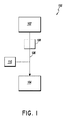
図1は、流体移動システム100の例示的な一実施形態を模式的に示している。流体移動システム100は、流体の適正な移動を妨げる異常を検出するように構成可能である。流体移動システム100は、本明細書に援用の特徴等、上記または本明細書に開示のさまざまな他の実施形態に関連して記載の特徴と類似または同一の特徴を含み得る。また、流体移動システム100は、'832特許および/または'911公開に図示または記載の任意の特徴を含み得る。流体移動システム100は、第1の流体容器102(たとえば、医薬瓶)、第2の流体容器104(たとえば、注射器)、および第1の流体容器102と第2の流体容器104との間の流体通路106を具備し得る。第1の流体容器102と第2の流体容器104との間に延びた流体通路106に対しては、空気チャンバ108が流体連通可能である。空気チャンバは、環境大気からの封鎖または隔離が可能である。システム100は、空気センサ110を具備し得る。本明細書において、用語「空気」は、その広範な通常の意味を有することを意図しており、たとえば空気センサ110により、流体移動システム100を通って移動する流体とは異なるものとして識別可能な気体のさまざまな組み合わせを含み得る。いくつかの状況において、空気チャンバの空気は、流体移動システム100を通って移動する流体の蒸発粒子を含んでいてもよい。空気センサ110は、流体移動システム100を通って移動する流体と空気とを区別するように構成可能である。たとえば、空気センサ110としては、(たとえば、光源および光検出器を具備した)光学センサが可能である。いくつかの実施形態において、空気センサ110は、(たとえば、流体を通過する光または流体を通過しない光の吸収によって)流体の有無を検出可能である。流体が存在しないことの検出は、空気の検出と同じにすることができる。たとえば、空気センサ110の光検出器が(たとえば、流体による光の吸収によって)閾値レベルを下回る光源からのある量の光を検出した場合、空気センサ110は、流体の検出を示すことができる。空気センサ110の光検出器が(たとえば、光を吸収する流体が存在せずに)閾値レベルを上回る光源からのある量の光を検出した場合、空気センサ110は、空気の検出を示すことができる。システム100は、通常動作時に空気チャンバ1
08の空気を空気センサが検出しないように構成可能である。流体通路の圧力が低下する異常の場合は、圧力低下の結果として、空気チャンバ108の空気が膨張可能である。空気センサ110は、膨張空気を検出するように位置決め可能である。また、空気センサ110は、空気の検出に応じて、異常の可能性を示すことができる。
FIG. 1 schematically illustrates an exemplary embodiment of a fluid movement system 100. The fluid movement system 100 can be configured to detect anomalies that prevent proper movement of the fluid. The fluid transfer system 100 may include features that are similar or identical to features described above or in connection with various other embodiments disclosed herein, such as features incorporated herein. The fluid transfer system 100 may also include any feature shown or described in the '832 patent and / or the' 911 publication. The fluid transfer system 100 includes a first fluid container 102 (e.g., a pharmaceutical bottle), a second fluid container 104 (e.g., a syringe), and a fluid between the first
It can be configured so that the air sensor does not detect 08 air. In the event of an abnormal pressure drop in the fluid passage, the air in the air chamber 108 can expand as a result of the pressure drop. The air sensor 110 can be positioned to detect expanded air. Further, the air sensor 110 can indicate the possibility of abnormality in response to the detection of air.
いくつかの実施形態において、空気センサ110は、第1の容器102が空であることの指標および異常の可能性の指標として、空気の検出に使用可能である。また、空気センサ110は、流体通路106の空気を検出するように位置決め可能である。第1の容器102が空になった場合は、第1の容器から空気が退出し、第2の容器104に向かって流体通路106を進行可能である。空気センサ110の検知箇所に空気が達すると、空気センサ110が空気を検出可能である。この状況において、空気センサ110による空気の検出は、第1の容器102が空になったことを示す。圧力が低下する異常が発生した場合、空気チャンバ内の空気は、流体通路106内へと膨張可能である。空気センサ110の検知箇所に膨張空気が達すると、空気センサ110が空気を検出可能である。この状況において、空気センサ110による空気の検出は、流体通路106内の圧力の低下を示し、これによって、異常が発生したことを示すことができる。
In some embodiments, the air sensor 110 can be used to detect air as an indicator that the
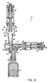
図2は、流体移動システム200の例示的な一実施形態を模式的に示している。流体移動システム200は、流体移動システム100または本明細書に開示のその他さまざまな実施形態の任意の特徴を含み得る。また、流体移動システム200は、'832特許および/または'911公開に図示および/または記載の任意の特徴を含み得る。流体移動システム200は、流体源容器202(たとえば、医薬瓶)、中間容器204(たとえば、注射器)、および流体移動先容器214(たとえば、点滴バッグ)を具備し得る。流体源容器202、中間容器204、および流体移動先容器214の結合には、流体移動モジュール212を使用可能である。図3は、流体移動モジュール212の例示的な一実施形態の斜視断面図である。図4は、図3の流体移動モジュール212の例示的な実施形態の分解斜視断面図である。流体移動モジュール212は、'832特許および/または'911公開に図示および/または記載の任意の特徴を含み得る。また、多くの変形例が考えられる。たとえば、図1に模式的に示すように、いくつかの実施形態においては、中間容器を用いることなく(たとえば、注射器ポンプを用いることなく)流体を流体源容器から移動先容器に移動させることができる。また、いくつかの実施形態においては、蠕動ポンプまたは中間容器(たとえば、注射器)を含まない他のポンプ装置を用いて流体を移動させることができる。
FIG. 2 schematically illustrates an exemplary embodiment of a
流体源容器202と中間容器204との間には、移動元流体通路206が延伸可能であり、また、流体移動モジュール212を通って延伸可能である。中間容器204と流体移動先容器214との間には、移動先流体通路216が延伸可能であり、また、流体移動モジュール212を通って延伸可能である。いくつかの実施形態においては、移動元流体通路206および移動先流体通路216の少なくとも一部が重複し得る。たとえば、中間容器204としては、移動元流体通路206および移動先流体通路216の両者が通過可能な開口部を含む注射器が可能である。移動元流体通路206には、移動元逆止弁218を位置決め可能であり、これは、流体源容器202から中間容器204への流体の通過を許可するとともに、中間容器204から流体源容器202への流体の通過を阻止または防止するように構成可能である。移動先流体通路216には、移動先逆止弁220を位置決め可能であり、これは、中間容器204から流体移動先容器214への流体の通過を許可するとともに、流体移動先容器214から中間容器204への流体の通過を阻止または防止するように構成可能である。
A source
流体移動モジュール212は、流体源容器202を当該移動モジュール212に結合するように構成されている移動元インターフェース222を具備し得る。移動元インターフェース222は、(たとえば、図3および図4に示していないアダプタを介して)流体源容器202に対して取り外し可能に取り付け得る。また、移動元インターフェース222は、流体移動モジュール212の移動元インターフェース222から流体源容器202が取り外された場合に移動元インターフェース222の開口を閉じるように構成されている弁224を具備し得る。移動元インターフェース222の弁224は、流体移動モジュール212の移動元インターフェース222に流体源容器202が取り付けられた場合に開くように構成可能である。流体移動モジュール212は、流体移動先容器214を当該移動モジュール212に結合するように構成されている移動先インターフェース226を具備し得る。移動先インターフェース226は、流体移動先容器214に対して取り外し可能に取り付け得る。また、移動先インターフェース226は、流体移動モジュール212の移動先インターフェース226から流体移動先容器214が取り外された場合に移動先インターフェース226の開口を閉じるように構成されている弁228を具備し得る。移動先インターフェース226の弁228は、流体移動モジュール212の移動先インターフェース226に流体移動先容器214が取り付けられた場合に開くように構成可能である。いくつかの実施形態において、流体移動モジュール212は、中間容器204を当該移動モジュール212に結合するように構成されている中間インターフェース230を具備し得る。中間インターフェース230は、中間容器204に対して取り外し可能に取り付け得る。いくつかの実施形態において、流体移動モジュール212は、流体移動モジュール212の一部として中間容器204を具備可能であり、中間インターフェース230は、永久的または一時的な取り付け具としても可能であるし、省略することも可能である。また、いくつかの実施形態において、流体源容器202および/または流体移動先容器214は、流体移動モジュールの一部として具備可能である。これにより、いくつかの実施形態において、移動元インターフェース222および/または移動先インターフェース226は、永久的または一時的な取り付け具としても可能であるし、省略することも可能である。
The
流体移動システム200は、空気チャンバ108および空気センサ110または本明細書に開示のその他さまざまな実施形態に関連して説明および/または図示する任意の機能を実行または包含可能な空気チャンバ208および空気センサ210を具備し得る。いくつかの実施形態において、流体移動モジュール212は、空気チャンバ208を具備し得る。空気チャンバ208は、流体移動モジュール212の内側の移動元流体通路206の一部と流体連通可能である。図示のように、空気チャンバは、流体が移動モジュール212に流通または存在している場合に、環境大気から封鎖または隔離されるように構成可能である。空気チャンバ208は、移動元インターフェースと中間容器204との間または移動元インターフェースと中間インターフェースとの間に配置可能である。流体移動モジュールは、空気センサに対して、移動元流体通路206中に存在し得る検知箇所における空気の検出を許可するように構成されている相互作用部232を備え得る。いくつかの実施形態において、相互作用部232は、空気センサ210が使用する光(たとえば、可視光、近赤外(NIR)、赤外(IR)光等)に対して実質的に透明とすることができる。空気センサの光が流体移動モジュール212の相互作用部232を通過する場合、ある少量の光の吸収、反射等の可能性があるものの、相互作用部232を実質的に透明とすることができるため、十分な光が透過して、空気センサ210が流体と空気とを確実に区別することができる。相互作用部232は、実質的に平坦とすることができ、これにより、実質的な変化を伴わない(たとえば、意図する光路からの実質的な屈折、散乱、あるいは逸脱を伴わない)光の検知箇所の通過を容易化可能である。いくつかの実施形態において、相互作用部232は、完全な平坦から逸脱したある少量の表面欠陥または不整を含むことができるものの、実質的に平坦とすることにより、空気センサ210が流体と空気とを確実に区別することができる。
The
いくつかの実施形態において、流体移動モジュール212は、本体234を具備し得る。図5は、本体234の例示的な一実施形態の斜視断面図である。図6は、図5の本体234の分解斜視断面図である。本体234は、本明細書に開示のその他の実施形態ならびに/または'832特許および/もしくは'911公開に記載の実施形態の任意の特徴を有し得る。流体通路206および/または216は、本体234を通って延伸可能である。本体234は、(たとえば、スナップ嵌合、干渉嵌合、クランプ、音波溶接、接着、または他の適当な取り付け機構を用いて)一体的に嵌合可能な第1の部分236(たとえば、上部)および第2の部分238(たとえば、下部)を具備し得る。第1の部分236および第2の部分238の部分は、互いに離隔して、間に流体通路206および/または216を形成可能である。移動元逆止弁218および/または移動先逆止弁220は、第1の部分236と第2の部分238との間に配設可能である。
In some embodiments, the
移動元インターフェース222および/または移動先インターフェース226は、本体234に結合可能である。たとえば、本体234は、移動元インターフェース222を本体234に結合するように構成可能な移動元取り付け部240を具備し得る。移動元取り付け部240は、たとえばオスまたはメス端部を具備し得る。いくつかの実施形態において、移動元インターフェース222は、当該移動元インターフェース222を本体234に結合するように構成されている取り付け部242を具備し得る。たとえば、取り付け部242は、メスまたはオス端部を具備し得る。いくつかの実施形態において、本体234の移動元取り付け部240は、(たとえば、スナップ嵌合、干渉嵌合、クランプ、音波溶接、接着、または他の適当な取り付け機構を用いて)移動元インターフェース222の取り付け部242に直接結合可能である。いくつかの実施形態においては、移動元取り付け部240と移動元インターフェース222の取り付け部242との間に、1つまたは複数の構成要素(たとえば、空気チャンバ208)を配設可能である。移動元インターフェース222は、'832特許および/または'911公開に記載されているような閉塞可能コネクタ(たとえば、閉塞可能オスコネクタ)を具備し得る。
The
本体234は、移動先インターフェース226を本体234に結合するように構成可能な移動先取り付け部244を具備し得る。移動先取り付け部244は、たとえばオスまたはメス端部を具備し得る。いくつかの実施形態において、移動先インターフェース226は、当該移動先インターフェース226を本体234に結合するように構成されている取り付け部246を具備し得る。たとえば、取り付け部246は、メスまたはオス端部を具備し得る。いくつかの実施形態において、本体234の移動先取り付け部244は、(たとえば、スナップ嵌合、干渉嵌合、クランプ、音波溶接、接着、または他の適当な取り付け機構を用いて)移動先インターフェース226の取り付け部246に直接結合可能である。いくつかの実施形態においては、移動先取り付け部244と移動先インターフェース226の取り付け部246との間に、1つまたは複数の構成要素を配設可能である。移動先インターフェース226は、'832特許および/または'911公開に記載されているような閉塞可能コネクタ(たとえば、閉塞可能オスコネクタ)を具備し得る。
The
図3および図4に示すように、中間インターフェース230は、本体234と一体化可能である。いくつかの実施形態において、中間インターフェース230としては、移動元インターフェース222および/または移動先インターフェース226と同様、本体234に結合可能なコネクタが可能である。いくつかの実施形態において、中間インターフェース230は、中間容器204が取り外された場合に中間インターフェース230の開口を閉塞可能な弁を具備し得る。
As shown in FIGS. 3 and 4, the
空気チャンバ208は、流体源容器202と中間容器204との間に位置決め可能である。また、空気チャンバ208は、流体移動モジュール212の一部として組み込み可能である。いくつかの実施形態において、空気チャンバ208は、移動元インターフェース222と移動元取り付け部240との間に配設可能である。いくつかの実施形態において、空気チャンバモジュール250は、空気チャンバ208を構成する内部空洞を有し得るハウジングを具備可能である。図7は、空気チャンバモジュール250の例示的な一実施形態の斜視断面図である。図8は、図7の空気チャンバモジュールの分解斜視断面図である。空気チャンバモジュール250は、当該空気チャンバモジュール250を本体234(たとえば、移動元取り付け部240)に結合するように構成可能な本体取り付け部248を具備し得る。本体取り付け部248としては、移動元取り付け部240のオスまたはメス端部に取り付け可能なメスまたはオス端部が可能である。空気チャンバモジュール250は、スナップ嵌合、干渉嵌合、クランプ、音波溶接、接着、または他の適当な取り付け機構を用いて、本体234に取り付け可能である。空気チャンバモジュール250は、当該空気チャンバモジュール250を移動元インターフェース222に結合するように構成可能な移動元取り付け部252を具備し得る。たとえば、移動元取り付け部252は、移動元インターフェース222の取り付け部242のオスまたはメス端部に取り付け可能なメスまたはオス端部を具備し得る。空気チャンバモジュール250は、スナップ嵌合、干渉嵌合、クランプ、音波溶接、接着、または他の適当な取り付け機構を用いて、移動元インターフェース222に取り付け可能である。
The
空気チャンバモジュール250は、(たとえば、スナップ嵌合、干渉嵌合、クランプ、音波溶接、接着、または他の適当な取り付け機構を用いて)一体的に嵌合可能な第1の部分254(たとえば、上部)および第2の部分256(たとえば、下部)を具備し得る。第1の部分254の少なくとも一部は、第2の部分256からの隔離によって、間に間隙を形成可能であり、この間隙は、空気を含んで空気チャンバ208を提供可能である。空気チャンバモジュール250は、第1の壁258(たとえば、内壁)と、内壁258から離隔して空気チャンバ用の間隙を間に形成する第2の壁260(たとえば、外壁)とを具備し得る。いくつかの場合、空気チャンバは、大略的に環状の形状を有し得る。第1の壁258としては、第1の部分254の一部(たとえば、いくつかの実施形態においては、移動元取り付け部252の一部)が可能であり、第2の壁260としては、第2の部分256の一部が可能である。本体取り付け部248と第2の壁260との間には、仕切り262を位置決め可能である。仕切り262は、移動元流体通路206に対して大略直角に延伸可能である。仕切り262は、流体の空気チャンバモジュール250の通過を可能とする開口264を有し得る。いくつかの実施形態において、第2の壁260は、仕切り262から第1の方向(たとえば、大略上方)に延伸可能であり、本体取り付け部248は、仕切り262から第2の方向(たとえば、大略下方)に延伸可能である。当業者であれば、本明細書の開示内容に基づいて、空気チャンバ208および/または空気チャンバモジュール250をその他さまざまな箇所に位置決め可能であり、図面に示す例示的な実施形態から空気チャンバモジュール250をさまざまに変更可能であることが了解されよう。
The
図9は、移動元流体通路206および移動先流体通路216に流体が存在する流体移動モジュール212の断面図である。図9は、移動元インターフェース222および移動先インターフェース226が閉じており、簡素化のため流体源容器202および流体移動先容器214を省略して示しているが、動作中は、流体源容器202を(開放弁224を有し得る)移動元インターフェース222に結合可能であることおよび/または流体移動先容器214を(開放弁228を有し得る)移動先インターフェース226に結合可能であることが了解される。動作中、注射器204のプランジャは、(たとえば、'832特許および/または'911公開に記載されているような電子的に制御される流体分注システムのアクチュエータによって)後退可能である。プランジャの後退により、流体源容器から流体通路206を介して中間容器204(たとえば、注射器)に流体を引き込み可能である。移動先逆止弁220は、プランジャが後退した場合の流体移動先容器214から中間容器側への流体の流れを阻止または防止可能である。移動元流体通路206は、アダプタ(たとえば、瓶アダプタ(図9には示さず))、移動元インターフェース222、空気チャンバモジュール250、および/または本体234を通って延伸可能である。注射器204のプランジャは、(たとえば、'832特許および/または'911公開に記載されているような電子的に制御される流体分注システムのアクチュエータによって)前進可能である。プランジャの前進によって、流体を中間容器(たとえば、注射器)から放出可能である。移動元逆止弁218は、放出流体が流体源容器202側に戻るのを阻止または防止可能である。放出流体は、中間容器204から移動先流体通路216を介して対象容器214まで通過可能である。移動先流体通路216は、本体234、移動先インターフェース226、および/またはアダプタ(たとえば、点滴バッグに取り付けられている管類(図9には示さず))を通って延伸可能である。たとえば、所望量の流体に対応した距離だけプランジャを後退させた後、プランジャを前進させて流体を流体移動先容器214内へと運ぶことにより、正確な量の流体を流体源容器202から流体移動先容器214に移動させることができる。別途詳細については、'832特許および/または'911公開にて提供されている。
FIG. 9 is a cross-sectional view of the
図9に示すように、いくつかの実施形態においては、移動元流体通路が空気チャンバモジュール250を通って延伸可能である。たとえば、流体は、空気チャンバモジュール250に対して、移動元取り付け部252を介した流入および本体取り付け部248を介した流出が可能である。空気チャンバ208は、移動元流体通路206と流体連通可能である。また、空気チャンバ208は、流体が移動元流体通路206を流れる通常の動作状態の下、大略静止したモードで空気が空気チャンバに保持されるように配向可能である。たとえば、空気チャンバ208は、流体の存在下および/または流体の流通中に(たとえば、第1の壁258によって)移動元流体通路206から少なくとも一部が分離されるように構成可能であり、開口部266によって、(たとえば、第1の壁258と非平行および/または流体の流通路と非平行の方向に)空気チャンバ208と移動元流体通路206とを流体連通可能である。いくつかの実施形態において、開口部266の形状としては、大略的に環状が可能である。空気チャンバ208は、通常の圧力状態(たとえば、流体移動システム200の通常動作時)において空気チャンバの空気が開口部266の上方に位置決め可能となるように、開口部の上方に位置決め可能である。動作中、いくつかの状況においては、何らかの流体が開口部266を通過可能であり、空気チャンバ208の下部に進入する可能性もある。空気は、流体よりも低密度であるため、空気チャンバ208の頂部へと上昇可能であり、空気は通常の圧力状態においては開口部266を通過しない。図9に示すように、いくつかの実施形態においては、流体源容器202と中間容器204との間、流体源容器102もしくは202と移動先容器104もしくは214との間、移動元インターフェース222と中間インターフェース230との間、ならびに/または中間インターフェース230と移動先インターフェース226との間において、通常動作時に、流体の連続流が移動元流体通路206、移動先流体通路216を通って延伸可能である。図9に見られるように、空気チャンバ208は、通常動作時に、流体の連続した切れ目のない経路の外側で空気が空気チャンバ208内となるように構成可能である。いくつかの実施形態において、流体移動モジュールは、通常動作時に、流体が空気チャンバ208を通過することなく移動元流体通路206に沿って流れるように構成可能である。空気チャンバ208は、移動元流体通路206の外側の空気が移動元流体通路206と流体連通するように、空気を一時停止させることができる。図10に関連して説明する通り、特定の状況下において(たとえば、異常または圧力低下が発生している場合)、空気チャンバ208の空気は、移動元流体通路206内へと膨張して、通常は移動元流体通路206に沿って延びる流体の連続流を遮断することができる。
As shown in FIG. 9, in some embodiments, the source fluid path can extend through the
たとえば、流体源容器202からの流体の退出を阻止または防止可能な異常が発生した場合は、プランジャの後退によって、流体通路に沿った圧力低下(たとえば、部分的な減圧)が生じ得る。図10は、(たとえば、移動元流体通路206の)圧力が低下した流体移動モジュール212を示した断面図である。圧力の低下によって、空気チャンバ208の空気が膨張し得る。いくつかの実施形態において、空気は、中間インターフェースおよび/または中間容器に向かって下流側に、開口部266を介して移動元流体通路206内へと膨張可能である。空気は、膨張して、検知箇所268に達し得る。空気センサ210(電子的に制御される流体分注システムの一部となり得る(図10には示さず))は、検知箇所268における空気を検出するように構成可能である。空気センサ210は、検知箇所268における空気を検出する場合、低圧状態が存在する可能性があることおよび/または異常が発生している可能性があることを示し得る信号を生成可能である。いくつかの実施形態において、電子的に制御される流体分注システムは、空気センサ210からの指標に応じて、(たとえば、プランジャの後退を停止させることにより)流体移動を停止可能である。いくつかの実施形態において、電子的に制御される流体分注システムは、空気センサ210からの指標に応じて、異常が発生している可能性をユーザに警告または通知可能である。
For example, if an anomaly occurs that can prevent or prevent fluid exit from the
いくつかの実施形態において、空気センサ210は、流体源容器202が空であることの指標として、空気の検出に使用可能である。したがって、空の流体源容器202の検出および低圧状態を生み出す異常の検出には、同じ空気センサ210を使用可能である。空気センサ210は、移動元流体通路206の空気を検出するように位置決め可能である。流体源容器202が空になった場合は、流体源容器202から空気が退出して、移動元流体通路206を進行可能である。空気センサ210の検知箇所268に空気が達すると、空気センサ210が空気を検出可能である。この状況において、空気センサ210による空気の検出は、流体源容器202が空になったことを示す。圧力が低下する異常が発生した場合、空気チャンバ208内の空気は、本明細書に記載の通り、流体通路206内へと膨張可能である。空気センサ210の検知箇所268に膨張空気が達すると、空気センサ210が空気を検出可能である。この状況において、空気センサ210による空気の検出は、流体通路206内の圧力の低下を示し、これによって、異常が発生したことを示すことができる。いくつかの実施形態において、空気センサ210が空気を検出する場合は、流体源容器202が空である可能性(たとえば、交換が必要)および/または異常が発生している可能性を示す通知を行うことができる。
In some embodiments, the
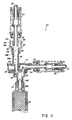
空気センサ210は、検知箇所がさまざまな異なる箇所となり得るように位置決め可能である。図11は、さまざまな考え得る検知箇所268a〜268eを示した断面図である。検知箇所286aは、空気チャンバモジュール250と移動元逆止弁218との間の移動元流体通路206中(たとえば、流体移動モジュール212の本体234の移動元取り付け部240中)に位置決め可能である。検知箇所268bは、空気チャンバモジュール250の移動元流体通路206中(たとえば、空気チャンバモジュール250の本体取り付け部248中)に位置決め可能である。いくつかの実施形態において、検知箇所268は、移動元流体通路206の外側に位置決め可能である。たとえば、検知箇所268cは、膨張空気が移動元流体通路206に進入する前に検知箇所268cに達するように、空気チャンバ208と移動元流体通路206との間に位置決め可能である。検知箇所268dは、移動元逆止弁218と中間容器204との間の流体通路206中(たとえば、中間インターフェース230中)に位置決め可能である。いくつかの実施形態において、検知箇所268eは、中間容器204の内側に配置可能である。いくつかの実施形態においては、上記または他の箇所のうちの2つ以上に複数の検知箇所を設けることができる。図11は、さまざまな異なる検知箇所268a〜268eを示しているが、単一の空気センサ210を使用して、図示の検知箇所268a〜268eのうちの1つにおける空気を検出可能であることが了解される。いくつかの実施形態においては、2つ以上の空気センサ210を使用可能である。また、図に示す例以外に、その他さまざまな検知箇所を使用可能である。
The
いくつかの状況において、検知箇所が空気チャンバ208の近くに位置決めされた実施形態では、検知箇所が空気チャンバ208から離れて位置決めされた実施形態よりも早く、システム200が異常(たとえば、低圧状態)を検出可能である。たとえば、低圧状態が生じると、膨張空気は、下流の検知箇所268bまたは268aよりも早く、上流の検知箇所268cに達する。したがって、検知箇所268の位置を変更することにより、システムが低圧を検出できる感度を調整可能である。いくつかの場合は、検知箇所を空気チャンバ208の極近くに位置決めすると、異常の可能性が誤って示されることがある。たとえば、空気チャンバ208の空気は、システム200の通常動作時に、(たとえば、許容範囲内の圧力の微小変化またはシステム200の移動によって)少量だけ移動または膨張する可能性がある。検知箇所268を空気チャンバ208の極近くに位置決めすると、空気の許容範囲内の微小膨張または移動によって、空気センサ210が空気を検出可能となる。図11に示すさまざまな検知箇所268a〜268eによって、システムが低圧を検出できる感度がさまざまに平衡可能である。
In some situations, an embodiment in which the sensing location is positioned near the
図12は、本明細書または'832特許および/もしくは'911公開に図示および/または記載の他の実施形態の任意の特徴を有し得る流体源容器202およびアダプタ270の断面図である。流体源容器202としては、瓶が可能であるが、いくつかの実施形態では他の種類の容器も使用可能である。アダプタ270は、当該アダプタ270を流体移動モジュール212に結合するように構成可能な流体移動モジュールインターフェース272を具備し得る。たとえば、流体移動モジュールインターフェース272としては、流体移動モジュール212の移動元インターフェース222(たとえば、閉塞可能オスコネクタ)に対して取り外し可能に取り付けられるように構成されているコネクタ(たとえば、閉塞可能メスコネクタ)が可能である。アダプタ270は、流体源容器202に結合されるように構成可能な移動元インターフェース274を具備し得る。移動元インターフェース274は、流体源容器202(たとえば、瓶)の隔膜に穴をあけるように構成可能な先鋭部を具備し得る。移動元インターフェース274は、流体源容器202からの流体の退出を許可するように構成可能な流体チャンネル276を具備し得る。流体チャンネル276は、移動元流体通路206の一部を構成可能である。移動元インターフェース274は、(たとえば、流体源容器202から流体が退出した場合に)流体源容器202への空気の進入を許可するように構成可能な空気入口チャンネル278を具備し得る。流体源容器202から退出する流体の体積は、空気で置き換え可能であるため、流体源容器202の内側での圧力低下(たとえば、部分的な減圧)の発生を阻止または防止可能である。
FIG. 12 is a cross-sectional view of a
アダプタ270は、空気に対して大略透過性であるが、流体に対しては大略非透過性の障壁280を具備し得る。障壁280によって、空気は、空気入口チャンネルに進入可能である。通常の状態においては、空気入口チャンネル278が空気を含み、流体源容器202からの流体が空気入口チャンネル278を介して障壁280まで進行することはない。ただし、(たとえば、不適切な装置の過剰振動および/または流体移動システムへの接続前の不適切な流体源容器の過加圧によって)流体が空気入口チャンネル278を介して障壁280まで進行する場合、障壁は、アダプタ270からの流体の退出を防止可能である。ただし、いくつかの状況において、障壁280が湿潤となった場合は、障壁280の空気透過性が低下またはゼロとなって、空気入口チャンネル278への空気の進入を阻止または防止可能である。流体が流体源容器202から引き出された場合に流体源容器に進入する空気がゼロまたは不十分であると、流体源容器202の内側の圧力低下(たとえば、部分的な減圧)が生じる可能性がある。圧力低下によって、(たとえば、注射器204のプランジャが後退した場合の)流体源容器202からの流体の退出を阻止または防止可能である。圧力低下は、流体源容器202と流体連通する領域(たとえば、空気チャンバ208)に拡がり得る。空気チャンバ208の空気は、膨張によって圧力低下を補償可能であり、空気センサ210は、本明細書に記載の通り、膨張空気を検出可能である。いくつかの実施形態において、空気チャンバ208の空気は、(たとえば、図9に示すように)通常の動作圧力において第1の体積を有し得る。移動元流体通路206の圧力が(たとえば、障壁280の障害によって)閾値を下回ると、空気は、第1の体積よりも大きく、空気を検知箇所268に位置決めするのに十分大きな第2の体積まで膨張し得る。当業者であれば、本明細書の開示内容に基づいて、圧力低下をもたらし得るその他さまざまな種類の異常(たとえば、管類のつぶれ、コネクタの障害、逆止弁の不調等)が発生する可能性があり、本明細書に記載のシステムおよび方法と類似のシステムおよび方法を用いて、これらの異常を検出可能であることが了解されよう。
The
図5および図6を再び参照して、移動元逆止弁218および/または移動先逆止弁220には、さまざまな異なる逆止弁構成を使用可能である。たとえば、ダックビル型逆止弁を使用可能である(たとえば、図5および図6に示す移動先逆止弁220を参照)。また、'832特許および/または'911公開に開示のその他さまざまな逆止弁構成を使用可能である。図5および図6に示すように、移動元逆止弁218は、ストッパ282を具備し得る。ストッパ282の形状としては、大略的に球状が可能である(たとえば、ボール逆止弁)が、他の形状をストッパ282に使用することも可能である。ストッパ282は、閉塞位置と開放位置との間で移動可能である。「開放」位置は、この分野の通常の意味に従って理解されるものとし、流体の十分な流れによって、製品が目的とする臨床機能を実行可能な位置を含む。「閉塞」位置は、この分野の通常の意味に従って理解されるものとし、使用を意図した製品の特定目的の用途における流体圧力の通常の範囲において流体の流れを完全に遮る位置または臨床的に大きな機能上の不都合を回避するのに必要な程度まで流体の流れを実質的に完全に遮る位置を含む。図5は、開放位置のストッパ282を示している。逆止弁218は、封止要素284を具備可能であり、ストッパ282は、閉塞位置にある場合に封止要素284に対して接触または隣接可能である。封止要素284は、ストッパ282が閉塞位置にある場合に、ストッパ282を封止するように構成可能である。たとえば、封止要素284は、弾性材料(たとえば、ゴム、シリコーン、ラテックス等)で形成可能であり、ストッパ282は、硬質または半硬質材料(たとえば、硬質プラスチックまたは金属)で形成可能である。封止要素284は、ストッパ282が封止要素284に隣接して封止を形成する場合に変形する可能性がある。いくつかの実施形態において、封止要素284としては硬質または半硬質材料が可能であり、ストッパ282としては弾性材料が可能であり、または、封止要素284およびストッパ282の両者が弾性材料で形成可能である。いくつかの実施形態において、封止要素284としては、流体移動モジュール212の1つまたは複数の内部壁が可能であり、ストッパ282は、流体移動モジュール212の1つまたは複数の内部壁を封止するように構成可能である。
いくつかの実施形態において、封止要素284としては、大略的に円形が可能である。図示のように、封止要素284は、Oリングを備え得る。いくつかの実施形態において、封止要素284を通る内部の流体流通路は、ストッパ282の直径または断面幅よりも小さな直径または断面幅を有する開口を備え得る。
Referring back to FIGS. 5 and 6, the
In some embodiments, the sealing
流体が第1の方向に(たとえば、流体源容器202から中間容器204に向かって)流れる場合、ストッパ282は、開放位置に移動して、封止要素284から離隔することにより、(たとえば、注射器204のプランジャが後退した場合に)流体が逆止弁218を流通可能となる。逆止弁218は、第2の方向に(たとえば、中間容器204から流体源容器202に向かって)流体が逆止弁218を通過することを阻止または防止可能である。流体は、(たとえば、注射器204のプランジャが前進した場合に)第2の方向に流れることを強制されると、ストッパ282を封止要素の方向に押すとともに、封止要素284に対して強固に押圧可能であり、第2の方向に流体が逆止弁218を通過することを防止または阻止可能である。いくつかの実施形態において、ストッパ282は、閉塞位置側に付勢可能である。いくつかの実施形態において、ストッパ282は、流体よりも低密度とすることができるため、流体の存在下で、浮上して封止要素284に接触する傾向にある。いくつかの実施形態においては、図5に示すように、ストッパ282がチャンバ内で自由に浮遊可能である(たとえば、周囲の要素に対して直接的に結合または固定されない)。チャンバは、ストッパ282が閉塞位置と開放位置との間で移動可能であるが、チャンバから退出することのないようにサイズ指定可能である。たとえば、ストッパ282を配置するように構成されている領域においては、ストッパ282の直径または断面幅を下流の流体流通開口の直径または断面幅よりも大きくすることができる。いくつかの実施形態においては、製造時のストッパ282の挿入を可能とするため、ストッパ282を配置するように構成されている領域においては、ストッパ282の直径または断面幅を上流の流体流通入口開口の直径または断面幅よりも小さいか、または概ね等しくすることができる。
When fluid flows in a first direction (e.g., from the
図13〜図18を参照して、いくつかの実施形態においては、付勢要素286がストッパ282を閉塞位置側に付勢可能である。付勢要素286としては、バネが可能である。たとえば、図13および図14に示すように、付勢要素286としては、ヘリカルコイルバネが可能である。図13は、閉塞位置の逆止弁218の例示的な一実施形態を示した側面図である。閉塞位置において、付勢要素286(たとえば、コイルバネ)は、封止要素284に対してストッパ282(たとえば、ボール)を押圧することにより、流体の逆止弁218の流通を防止または阻止する。図14は、開放位置の図13の逆止弁218を示している。開放位置においては、コイルバネ286を圧縮可能であり、ストッパ282が封止要素284から離隔して、流体が逆止弁218を通過可能である。
With reference to FIGS. 13-18, in some embodiments, a biasing
図15は、閉塞位置の逆止弁218の例示的な別の実施形態を示した側面図である。図16は、開放位置の図15の逆止弁218の側面図である。付勢要素286としては、ストッパ282が開放位置まで押された場合(図16)に変形可能な弾性体が可能である。弾性体は、付勢によって、変形していない形状に戻ることができ、これによって、ストッパ282を封止要素284側に押圧する力を印加可能である。いくつかの実施形態において、付勢要素286の弾性体は、少なくとも1つの空洞288を有し得る。逆止弁218が閉塞位置にある場合、空洞288は、(図15に示すように)少なくとも一部が開いた構成となり得る。逆止弁218が開放位置にある場合、空洞288は、(図16に示すように)少なくとも一部がつぶれた位置となり得る。少なくとも1つの空洞288がつぶれることにより、弾性体は、閉塞位置から開放位置まで容易に変形可能となる。
FIG. 15 is a side view illustrating another exemplary embodiment of
図17は、閉塞位置の逆止弁218の例示的な別の実施形態を示した側面図である。図18は、開放位置の図17の逆止弁218の側面図である。付勢要素286は、封止要素284に対してストッパ282を引っ張ることができる1つまたは複数の柔軟なテザー290を具備可能である。逆止弁218が閉塞位置にある場合、1つまたは複数のテザー290は、(図17に示すように)第1の長さを有し得る。逆止弁218が開放位置にある場合、1つまたは複数のテザー290は、(図18に示すように)伸長して、第1の長さよりも大きな第2の長さを有し得る。1つまたは複数のテザー290は、(たとえば、結合要素292(ストッパ282の直径よりも小さな直径を有し得る環状要素が可能)を介して)ストッパ282に結合可能である。いくつかの実施形態において、1つまたは複数のテザー290は、封止要素284に結合可能である(たとえば、1つまたは複数のテザー290は、封止要素284と一体的に形成可能である)。いくつかの実施形態において、1つまたは複数のテザー290は、逆止弁218を囲む内部壁と結合可能である。
FIG. 17 is a side view illustrating another exemplary embodiment of
図19は、閉塞位置の逆止弁218の例示的な別の実施形態の側面図である。図20は、開放位置の図19の逆止弁218の側面図である。いくつかの実施形態において、付勢要素286およびストッパ282は、単一の要素に組み込み可能である。たとえば、逆止弁218は、封止要素284(たとえば、弾性部材または流体移動モジュール212の内部壁)を封止するように構成可能なストッパ部282(たとえば、上部)を具備し得る。逆止弁218は、付勢要素286を具備可能であり、これは、たとえば図15および図16に関連して説明した実施形態と同様に、ストッパ部282を閉塞位置側に付勢するように構成可能な弾性体が考えられる。付勢要素286は、少なくとも1つの空洞288を含み得る。逆止弁218が閉塞位置にある場合、空洞288は、(図19に示すように)少なくとも一部が開いた構成となり得る。逆止弁218が開放位置にある場合、空洞288は、(図20に示すように)少なくとも一部がつぶれた位置となり得る。少なくとも1つの空洞288がつぶれることにより、付勢要素286は、閉塞位置から開放位置まで容易に変形可能となる。いくつかの実施形態において、ストッパ部282は、付勢要素286と一体的に形成可能である。いくつかの実施形態において、ストッパ部282は、付勢要素286から独立して形成可能であり、(たとえば、接着または他の適当な取り付け機構によって)付勢要素286に結合可能である。
FIG. 19 is a side view of another exemplary embodiment of a
図13〜図20において、逆止弁218は、単独で示しており、周囲の構成要素(たとえば、流体移動モジュール212)は、簡素化のため図示を省略している。図12〜図20は、移動元逆止弁218の例示的な実施形態を示している。移動先逆止弁220は、移動元逆止弁218に関連して図示(たとえば、図13〜図20)および説明した特徴と類似または同一の特徴を含み得る。
13 to 20, the
図21は、少なくとも1つの逆止弁を具備した流体移動モジュール212の例示的な一実施形態の断面図である。逆止弁218は、本明細書に記載の通り、閉塞位置と開放位置との間で移動可能なストッパ部282を具備し得る。図21は、開放位置のストッパ部282を示している。流体移動モジュール212は、ストッパ部282が開放位置(たとえば、完全開放位置)にある場合に当該ストッパ部282と接触するように構成可能な突起283を具備し得る。突起283は、(たとえば、流体の流れまたは流体圧力がストッパ部を閉塞位置側に強制する場合に)ストッパ部282の開放位置から閉塞位置への移行を容易化するように構成可能である。たとえば、突起283は、ストッパ部282が流体移動モジュール212の内部壁に張り付くことを阻止または防止可能である。突起283は、ストッパ部282が内部壁側に移動した場合に当該突起283に接触または隣接するように、内部壁から(たとえば、上方に)延伸可能である。突起283は、ストッパ部282が開放位置にある場合にストッパ部282を内部壁から離隔させるように構成可能である。いくつかの実施形態においては、開放位置のストッパ部282と突起283の隣接または近傍の内部壁との間の間隙によって、ストッパ部282の閉塞位置への移行を容易化可能である。たとえば、流体の流れまたは流体圧力が適用された場合、流体は、ストッパ部282と内部壁との間の間隙に進入し、ストッパ部282を内部壁から離して閉塞位置側に押すことができる。いくつかの実施形態において、ストッパ部282と突起との間の接触面積は、突起283を省略した場合にストッパ部282と内部壁との間に生じる接触面積よりも小さくすることができる。突起283は、ストッパ部282との接触面積を小さくするように先鋭化または曲線化可能な先端部を含み得る。また、先端部は、平坦な形状を有することができ、その他さまざまな形状も使用可能である。いくつかの実施形態において、流体移動モジュール212は、ストッパ部282の移動を容易化するように構成可能な複数の突起283を具備し得る。いくつかの実施形態において、突起283としては、細長の畝部が可能である。
FIG. 21 is a cross-sectional view of an exemplary embodiment of a
以上、添付の図面に関連して、例示的な実施形態を説明した。上記例示的な実施形態は、当業者が本明細書に記載の装置、システム、方法等を構成および使用できる詳細度で説明している。当業者であれば、本明細書の開示内容に基づいて、多種多様な変形例が可能であることが了解されよう。構成要素、要素、および/またはステップは、変更、追加、削除、または再構成可能である。また、処理ステップの追加、削除、または並び替えが可能である。以上、特定の実施形態を明示的に説明したが、当業者には、本開示内容に基づいて、他の実施形態も明らかとなろう。 The exemplary embodiments have been described above with reference to the accompanying drawings. The above exemplary embodiments are described in sufficient detail to enable those skilled in the art to make and use the devices, systems, methods, and the like described herein. One skilled in the art will appreciate that a wide variety of variations are possible based on the disclosure herein. Components, elements, and / or steps can be changed, added, deleted, or reconfigured. In addition, processing steps can be added, deleted, or rearranged. Although specific embodiments have been explicitly described above, other embodiments will be apparent to those skilled in the art based on the present disclosure.
本明細書に記載のシステムおよび方法のいくつかの態様は、たとえばコンピュータソフトウェア、ハードウェア、ファームウェア、またはソフトウェア、ハードウェア、およびファームウェアの任意の組み合わせを用いて実施可能であるのが好都合である。ソフトウェアは、本明細書に記載の機能を実行するためのコンピュータ実行可能コードを含み得る。いくつかの実施形態において、コンピュータ実行可能コードは、1つまたは複数の汎用コンピュータによって実行される。ただし、当業者には当然のことながら、本開示内容に照らせば、汎用コンピュータ上で実行されるソフトウェアを用いて実現可能な如何なるモジュールも、ハードウェア、ソフトウェア、ファームウェア、またはこれらの組み合わせを用いて実現可能である。たとえば、このようなモジュールは、集積回路の組み合わせによって、ハードウェアで十分に実現可能である。この代替または追加として、このようなモジュールは、汎用コンピュータではなく、本明細書に記載の特定の機能を実行するように設計されている専用コンピュータを用いて、全体的または部分的に実現可能である。 Conveniently, some aspects of the systems and methods described herein may be implemented using, for example, computer software, hardware, firmware, or any combination of software, hardware, and firmware. The software may include computer executable code for performing the functions described herein. In some embodiments, the computer executable code is executed by one or more general purpose computers. However, as will be appreciated by those skilled in the art, in light of the present disclosure, any module that can be implemented using software running on a general purpose computer may be implemented using hardware, software, firmware, or a combination thereof. It is feasible. For example, such a module can be sufficiently realized by hardware by a combination of integrated circuits. As an alternative or addition, such modules may be implemented in whole or in part using a dedicated computer that is designed to perform the specific functions described herein, rather than a general purpose computer. is there.
以上、特定の実施形態を明示的に説明したが、当業者には、本開示内容に基づいて、他の実施形態も明らかとなろう。したがって、本発明の範囲は、明示的に説明した実施形態のみならず、1つもしくは複数の公開公報としての公開または1つもしくは複数の特許としての発行が最終的になされる特許請求の範囲を参照して規定されるものである。 Although specific embodiments have been explicitly described above, other embodiments will be apparent to those skilled in the art based on the present disclosure. Accordingly, the scope of the present invention includes not only the embodiments explicitly described, but also the scope of the claims that are finally published as one or more publications or issued as one or more patents. It is defined by reference.
100 流体移動システム
102 第1の流体容器
104 第2の流体容器
106 流体通路
108 空気チャンバ
110 空気センサ
200 流体移動システム
202 流体源容器
204 中間容器
206 移動元流体通路
208 空気チャンバ
210 空気センサ
212 流体移動モジュール
214 流体移動先容器
216 移動先流体通路
218 移動元逆止弁
220 移動先逆止弁
222 移動元インターフェース
224 弁
226 移動先インターフェース
228 弁
230 中間インターフェース
232 相互作用部
234 本体
236 第1の部分
238 第2の部分
240 移動元取り付け部
242 取り付け部
244 移動先取り付け部
246 取り付け部
248 本体取り付け部
250 空気チャンバモジュール
252 移動元取り付け部
254 第1の部分
256 第2の部分
258 第1の壁
260 第2の壁
262 仕切り
264 開口
266 開口部
268 検知箇所
268a 検知箇所
268b 検知箇所
268c 検知箇所
268d 検知箇所
268e 検知箇所
270 アダプタ
272 流体移動モジュールインターフェース
274 移動元インターフェース
276 流体チャンネル
278 空気入口チャンネル
280 障壁
282 ストッパ
283 突起
284 封止要素
286 付勢要素
288 空洞
290 テザー
100 fluid transfer system
102 First fluid container
104 Second fluid container
106 Fluid passage
108 Air chamber
110 Air sensor
200 Fluid transfer system
202 Fluid source container
204 Intermediate container
206 Source fluid path
208 Air chamber
210 Air sensor
212 Fluid transfer module
214 Fluid destination container
216 Destination fluid passage
218 Source check valve
220 Destination check valve
222 Source interface
224 valves
226 Destination interface
228 valves
230 Intermediate interface
232 interaction part
234 body
236 1st part
238 Second part
240 Source mounting part
242 Mounting section
244 Destination attachment
246 Mounting section
248 Body attachment
250 air chamber module
252 Source mounting part
254 1st part
256 Second part
258 1st wall
260 Second wall
262 divider
264 aperture
266 opening
268 Detection location
268a Detection location
268b Detection location
268c Detection location
268d Detection location
268e Detection location
270 adapter
272 Fluid Movement Module Interface
274 Source interface
276 fluid channel
278 air inlet channel
280 barriers
282 Stopper
283 protrusion
284 Sealing element
286 Energizing elements
288 cavity
290 Tether
Claims (25)
注射器のプランジャを後退させて、第1の体積の流体を流体源容器から移動元流体通路を介して前記注射器に引き込むステップであり、前記流体源容器と前記注射器との間の前記移動元流体通路に対して空気チャンバが流体連通する、ステップと、
前記注射器の前記プランジャを後退させて、第2の体積の流体を前記移動元流体通路から前記注射器に引き込むステップであり、前記流体源容器と前記注射器との間の前記流体通路中の検知箇所まで、前記空気チャンバ中の空気が膨張するように、前記流体源容器からの流体の退出が妨げられる、ステップと、
前記流体源容器と前記注射器との間の前記移動元流体通路中の前記検知箇所における前記空気を空気センサで識別するステップと、
前記流体通路中の前記検知箇所における前記空気の識別に応じて、前記注射器の前記プランジャの後退を停止するステップと、
を含む、方法。 A method of moving fluid from a fluid source container to a syringe comprising:
Retracting a plunger of the syringe to draw a first volume of fluid from the fluid source container through the source fluid path into the syringe, the source fluid path between the fluid source container and the syringe An air chamber in fluid communication with respect to
Retracting the plunger of the syringe to draw a second volume of fluid from the source fluid passage into the syringe, up to a sensing location in the fluid passage between the fluid source container and the syringe Evacuating fluid from the fluid source container such that air in the air chamber expands; and
Identifying the air at the detection location in the source fluid path between the fluid source container and the syringe with an air sensor;
Stopping retraction of the plunger of the syringe in response to identifying the air at the detection location in the fluid passageway;
Including the method.
流体源容器に接続され、前記流体源容器と流体連通するように構成されている移動元インターフェースと、
流体移動先容器に接続され、前記流体移動先容器と流体連通するように構成されている移動先インターフェースと、
中間容器または中間容器に接続されるように構成されている中間インターフェースと、
前記移動元インターフェースと前記中間容器または前記中間インターフェースとの間に延びた移動元流体通路であって、前記流体源容器から前記中間容器までの流体の通過を可能にするように構成されている、移動元流体通路と、
前記中間容器または前記中間インターフェースと前記移動先インターフェースとの間に延びた移動先流体通路であって、前記中間容器から前記流体移動先容器までの流体の通過を可能にするように構成されている、移動先流体通路と、
前記移動元流体通路と流体連通する空気チャンバであって、前記移動元流体通路内の圧力が閾値を下回る場合に、当該空気チャンバからの空気が検知箇所まで膨張するように構成されている、空気チャンバと、
前記電子的に制御される流体分注システムに対して、前記空気チャンバから前記検知箇所まで膨張した前記空気の検出を許可するように構成されている相互作用部と、
を備える、流体移動モジュール。 A fluid transfer module configured to be removably attachable to an electronically controlled fluid dispensing system comprising:
A source interface connected to the fluid source container and configured to be in fluid communication with the fluid source container;
A destination interface connected to the fluid destination container and configured to be in fluid communication with the fluid destination container;
An intermediate interface configured to be connected to the intermediate container or the intermediate container;
A source fluid passage extending between the source interface and the intermediate container or the intermediate interface, configured to allow passage of fluid from the fluid source container to the intermediate container; A source fluid path;
A destination fluid passage extending between the intermediate container or the intermediate interface and the destination interface, configured to allow passage of fluid from the intermediate container to the fluid destination container A destination fluid passage,
An air chamber in fluid communication with the source fluid passage, wherein the air from the air chamber is configured to expand to a detection location when the pressure in the source fluid passage is below a threshold value. A chamber;
An interaction unit configured to allow the electronically controlled fluid dispensing system to detect the air expanded from the air chamber to the sensing location;
A fluid transfer module comprising:
前記空気チャンバと、
当該空気チャンバモジュールを前記本体の前記移動元取り付け部に結合するように構成されている本体取り付け部と、
当該空気チャンバモジュールを前記移動元インターフェースに結合するように構成されている移動元取り付け部と、
を有する、空気チャンバモジュールを備える、請求項13に記載の流体移動モジュール。 An air chamber module,
The air chamber;
A body attachment configured to couple the air chamber module to the source attachment of the body;
A source attachment configured to couple the air chamber module to the source interface;
14. The fluid transfer module of claim 13, comprising an air chamber module having:
前記移動元インターフェースと前記流体源容器との間に配設されているアダプタであって、前記流体源容器から流体が抜かれた場合に、空気が前記流体源容器に進入するように構成されている空気入口および障壁を備える、アダプタと、
をさらに備える、請求項7に記載の流体移動モジュール。 A fluid source container;
An adapter disposed between the source interface and the fluid source container, and configured to allow air to enter the fluid source container when fluid is removed from the fluid source container. An adapter comprising an air inlet and a barrier;
8. The fluid movement module of claim 7, further comprising:
前記電子的に制御される流体分注システムに対して取り外し可能に取り付けられている請求項7に記載の流体移動モジュールと、
を備える、流体移動システム。 An electronically controlled fluid dispensing system;
The fluid transfer module of claim 7 detachably attached to the electronically controlled fluid dispensing system;
A fluid transfer system comprising:
Applications Claiming Priority (3)
| Application Number | Priority Date | Filing Date | Title |
|---|---|---|---|
| US201361907995P | 2013-11-22 | 2013-11-22 | |
| US61/907,995 | 2013-11-22 | ||
| PCT/US2014/066645 WO2015077466A1 (en) | 2013-11-22 | 2014-11-20 | Fluid transfer devices and methods of use |
Publications (2)
| Publication Number | Publication Date |
|---|---|
| JP2017501766A true JP2017501766A (en) | 2017-01-19 |
| JP2017501766A5 JP2017501766A5 (en) | 2017-12-28 |
Family
ID=53180139
Family Applications (1)
| Application Number | Title | Priority Date | Filing Date |
|---|---|---|---|
| JP2016533117A Pending JP2017501766A (en) | 2013-11-22 | 2014-11-20 | Fluid moving device and method of use |
Country Status (7)
| Country | Link |
|---|---|
| US (1) | US20160256632A1 (en) |
| EP (1) | EP3071168A4 (en) |
| JP (1) | JP2017501766A (en) |
| CN (1) | CN105934229A (en) |
| AU (1) | AU2014352937A1 (en) |
| CA (1) | CA2930733A1 (en) |
| WO (1) | WO2015077466A1 (en) |
Cited By (1)
| Publication number | Priority date | Publication date | Assignee | Title |
|---|---|---|---|---|
| WO2019103160A1 (en) * | 2017-11-27 | 2019-05-31 | 株式会社ヘリオス | Adapter for cell drug vessel, multi-passage adapter for cell drug vessel, and cell drug transfer system and transfer method using same |
Families Citing this family (10)
| Publication number | Priority date | Publication date | Assignee | Title |
|---|---|---|---|---|
| ES2793953T3 (en) | 2009-07-29 | 2020-11-17 | Icu Medical Inc | Fluid transfer procedures |
| JP6307440B2 (en) | 2011-12-22 | 2018-04-04 | アイシーユー・メディカル・インコーポレーテッド | Fluid transfer device and method of use |
| AU2014353184B2 (en) | 2013-11-25 | 2017-08-17 | Icu Medical, Inc. | Methods and system for filling IV bags with therapeutic fluid |
| US10413662B2 (en) * | 2015-05-14 | 2019-09-17 | Carefusion 303, Inc. | Priming apparatus and method |
| WO2017096072A1 (en) | 2015-12-04 | 2017-06-08 | Icu Medical, Inc. | Systems methods and components for transferring medical fluids |
| USD851745S1 (en) | 2016-07-19 | 2019-06-18 | Icu Medical, Inc. | Medical fluid transfer system |
| WO2018022640A1 (en) | 2016-07-25 | 2018-02-01 | Icu Medical, Inc. | Systems, methods, and components for trapping air bubbles in medical fluid transfer modules and systems |
| US10463573B2 (en) * | 2016-08-03 | 2019-11-05 | Shinva Ande Healthcare Apparatus Co., Ltd | Sealed fluid transfer device and sealed fluid transfer method |
| CN110545859B (en) * | 2017-05-19 | 2021-05-18 | 萨摩亚商艾得卡医疗股份有限公司 | Closed system medicine dispensing and feeding device |
| US11590057B2 (en) | 2020-04-03 | 2023-02-28 | Icu Medical, Inc. | Systems, methods, and components for transferring medical fluids |
Citations (1)
| Publication number | Priority date | Publication date | Assignee | Title |
|---|---|---|---|---|
| JP2013500774A (en) * | 2009-07-29 | 2013-01-10 | アイシーユー・メディカル・インコーポレーテッド | Fluid transfer device and method of use thereof |
Family Cites Families (10)
| Publication number | Priority date | Publication date | Assignee | Title |
|---|---|---|---|---|
| US4410321A (en) * | 1982-04-06 | 1983-10-18 | Baxter Travenol Laboratories, Inc. | Closed drug delivery system |
| US6695817B1 (en) * | 2000-07-11 | 2004-02-24 | Icu Medical, Inc. | Medical valve with positive flow characteristics |
| ATE523218T1 (en) * | 2000-07-20 | 2011-09-15 | Acist Medical Sys Inc | SYRINGE Plunger LOCKING MECHANISM |
| US7998134B2 (en) * | 2007-05-16 | 2011-08-16 | Icu Medical, Inc. | Medical connector |
| DE602007014252D1 (en) * | 2006-10-25 | 2011-06-09 | Icu Medical Inc | MEDICAL CONNECTOR |
| EP2351550A1 (en) * | 2008-11-25 | 2011-08-03 | JMS Co., Ltd. | Connector |
| US8454579B2 (en) * | 2009-03-25 | 2013-06-04 | Icu Medical, Inc. | Medical connector with automatic valves and volume regulator |
| CN104287966B (en) * | 2009-05-04 | 2017-03-15 | 瓦莱里塔斯公司 | Fluid conveying device |
| JP5709905B2 (en) * | 2010-02-24 | 2015-04-30 | メディモップ・メディカル・プロジェクツ・リミテッド | Liquid transfer device including vial adapter with vent |
| JP6307440B2 (en) * | 2011-12-22 | 2018-04-04 | アイシーユー・メディカル・インコーポレーテッド | Fluid transfer device and method of use |
-
2014
- 2014-11-20 EP EP14863332.4A patent/EP3071168A4/en not_active Withdrawn
- 2014-11-20 CN CN201480073743.XA patent/CN105934229A/en active Pending
- 2014-11-20 CA CA2930733A patent/CA2930733A1/en not_active Abandoned
- 2014-11-20 AU AU2014352937A patent/AU2014352937A1/en not_active Abandoned
- 2014-11-20 JP JP2016533117A patent/JP2017501766A/en active Pending
- 2014-11-20 WO PCT/US2014/066645 patent/WO2015077466A1/en active Application Filing
-
2016
- 2016-05-16 US US15/156,257 patent/US20160256632A1/en not_active Abandoned
Patent Citations (1)
| Publication number | Priority date | Publication date | Assignee | Title |
|---|---|---|---|---|
| JP2013500774A (en) * | 2009-07-29 | 2013-01-10 | アイシーユー・メディカル・インコーポレーテッド | Fluid transfer device and method of use thereof |
Cited By (4)
| Publication number | Priority date | Publication date | Assignee | Title |
|---|---|---|---|---|
| WO2019103160A1 (en) * | 2017-11-27 | 2019-05-31 | 株式会社ヘリオス | Adapter for cell drug vessel, multi-passage adapter for cell drug vessel, and cell drug transfer system and transfer method using same |
| JPWO2019103160A1 (en) * | 2017-11-27 | 2020-12-17 | 株式会社ヘリオス | Adapter for cell drug container, multiple adapter for cell drug container, and cell drug transfer system and transfer method using this |
| JP7271436B2 (en) | 2017-11-27 | 2023-05-11 | 株式会社ヘリオス | Cellular medicine transfer method |
| US11752069B2 (en) | 2017-11-27 | 2023-09-12 | Healios K. K. | Method for transferring cellular medicine using a cellular medicine transfer system |
Also Published As
| Publication number | Publication date |
|---|---|
| US20160256632A1 (en) | 2016-09-08 |
| WO2015077466A1 (en) | 2015-05-28 |
| AU2014352937A1 (en) | 2016-06-16 |
| CN105934229A (en) | 2016-09-07 |
| EP3071168A1 (en) | 2016-09-28 |
| CA2930733A1 (en) | 2015-05-28 |
| EP3071168A4 (en) | 2017-08-02 |
Similar Documents
| Publication | Publication Date | Title |
|---|---|---|
| JP2017501766A (en) | Fluid moving device and method of use | |
| JP5829608B2 (en) | Fluid transfer device and method of use thereof | |
| JP4870134B2 (en) | Adapter for feeding device | |
| US11097069B2 (en) | Air in-line sensing system for IV infusion lines | |
| ES2334583T3 (en) | SURGICAL CAST. | |
| CN104204517A (en) | Piston pump, device for feeding and metering a fluid for medical purposes by means of a piston pump | |
| CN101197222B (en) | Pressure switch | |
| US9670052B2 (en) | Fuel dispensing nozzle having attitude sensing arrangement | |
| US20230285733A1 (en) | Prime tube configurations for syringe | |
| KR101556087B1 (en) | drainage Bag | |
| CN105007992B (en) | Lung demand valves | |
| US10518026B2 (en) | Drug administration mechanism, method for using drug administration mechanism, and pump unit for drug administration mechanism | |
| US8844642B2 (en) | Automatic flow restrictor for firefighting apparatus | |
| JP6475957B2 (en) | Dosing mechanism | |
| JP2017074359A (en) | Suction apparatus | |
| EP2874582B1 (en) | Aspiration cassette with gas and debris management | |
| ES2347087T3 (en) | MEANS OF DETECTION OF STEAM RECOVERY. | |
| TWI427275B (en) | Fluid measuring apparatus | |
| JP2021066528A (en) | Fluid supply device |
Legal Events
| Date | Code | Title | Description |
|---|---|---|---|
| A521 | Request for written amendment filed |
Free format text: JAPANESE INTERMEDIATE CODE: A523 Effective date: 20171117 |
|
| A621 | Written request for application examination |
Free format text: JAPANESE INTERMEDIATE CODE: A621 Effective date: 20171117 |
|
| A977 | Report on retrieval |
Free format text: JAPANESE INTERMEDIATE CODE: A971007 Effective date: 20180822 |
|
| A131 | Notification of reasons for refusal |
Free format text: JAPANESE INTERMEDIATE CODE: A131 Effective date: 20180910 |
|
| A02 | Decision of refusal |
Free format text: JAPANESE INTERMEDIATE CODE: A02 Effective date: 20190408 |